JP3940596B2 - Illumination light source - Google Patents
Illumination light source Download PDFInfo
- Publication number
- JP3940596B2 JP3940596B2 JP2001382193A JP2001382193A JP3940596B2 JP 3940596 B2 JP3940596 B2 JP 3940596B2 JP 2001382193 A JP2001382193 A JP 2001382193A JP 2001382193 A JP2001382193 A JP 2001382193A JP 3940596 B2 JP3940596 B2 JP 3940596B2
- Authority
- JP
- Japan
- Prior art keywords
- led
- light emitting
- light source
- emitting diode
- blue
- Prior art date
- Legal status (The legal status is an assumption and is not a legal conclusion. Google has not performed a legal analysis and makes no representation as to the accuracy of the status listed.)
- Expired - Fee Related
Links
Images


Classifications
-
- H10W90/00—
-
- F—MECHANICAL ENGINEERING; LIGHTING; HEATING; WEAPONS; BLASTING
- F21—LIGHTING
- F21K—NON-ELECTRIC LIGHT SOURCES USING LUMINESCENCE; LIGHT SOURCES USING ELECTROCHEMILUMINESCENCE; LIGHT SOURCES USING CHARGES OF COMBUSTIBLE MATERIAL; LIGHT SOURCES USING SEMICONDUCTOR DEVICES AS LIGHT-GENERATING ELEMENTS; LIGHT SOURCES NOT OTHERWISE PROVIDED FOR
- F21K9/00—Light sources using semiconductor devices as light-generating elements, e.g. using light-emitting diodes [LED] or lasers
- F21K9/20—Light sources comprising attachment means
- F21K9/23—Retrofit light sources for lighting devices with a single fitting for each light source, e.g. for substitution of incandescent lamps with bayonet or threaded fittings
- F21K9/233—Retrofit light sources for lighting devices with a single fitting for each light source, e.g. for substitution of incandescent lamps with bayonet or threaded fittings specially adapted for generating a spot light distribution, e.g. for substitution of reflector lamps
-
- F—MECHANICAL ENGINEERING; LIGHTING; HEATING; WEAPONS; BLASTING
- F21—LIGHTING
- F21Y—INDEXING SCHEME ASSOCIATED WITH SUBCLASSES F21K, F21L, F21S and F21V, RELATING TO THE FORM OR THE KIND OF THE LIGHT SOURCES OR OF THE COLOUR OF THE LIGHT EMITTED
- F21Y2113/00—Combination of light sources
- F21Y2113/10—Combination of light sources of different colours
- F21Y2113/13—Combination of light sources of different colours comprising an assembly of point-like light sources
-
- F—MECHANICAL ENGINEERING; LIGHTING; HEATING; WEAPONS; BLASTING
- F21—LIGHTING
- F21Y—INDEXING SCHEME ASSOCIATED WITH SUBCLASSES F21K, F21L, F21S and F21V, RELATING TO THE FORM OR THE KIND OF THE LIGHT SOURCES OR OF THE COLOUR OF THE LIGHT EMITTED
- F21Y2115/00—Light-generating elements of semiconductor light sources
- F21Y2115/10—Light-emitting diodes [LED]
-
- H10W72/884—
-
- Y—GENERAL TAGGING OF NEW TECHNOLOGICAL DEVELOPMENTS; GENERAL TAGGING OF CROSS-SECTIONAL TECHNOLOGIES SPANNING OVER SEVERAL SECTIONS OF THE IPC; TECHNICAL SUBJECTS COVERED BY FORMER USPC CROSS-REFERENCE ART COLLECTIONS [XRACs] AND DIGESTS
- Y10—TECHNICAL SUBJECTS COVERED BY FORMER USPC
- Y10S—TECHNICAL SUBJECTS COVERED BY FORMER USPC CROSS-REFERENCE ART COLLECTIONS [XRACs] AND DIGESTS
- Y10S362/00—Illumination
- Y10S362/80—Light emitting diode
Landscapes
- Engineering & Computer Science (AREA)
- Physics & Mathematics (AREA)
- Microelectronics & Electronic Packaging (AREA)
- Optics & Photonics (AREA)
- General Engineering & Computer Science (AREA)
- Led Device Packages (AREA)
- Non-Portable Lighting Devices Or Systems Thereof (AREA)
- Led Devices (AREA)
Description
【0001】
【発明の属する技術分野】
本発明は、発光ダイオードを備えた照明光源に関する。
【0002】
【従来の技術】
発光ダイオード(以下、「LED」と称する。)は、小型で効率が良く鮮やかな色の発光を示す半導体素子であり、スペクトル半値幅が狭いため高い色純度を有している。近年、青色LEDが実用化され、それにより赤、緑、青の3色が揃い、LEDを用いて白色発光を行うことが可能なった。
【0003】
【発明が解決しようとする課題】
従来、LEDは主に表示素子としての応用展開がなされてきたために、LEDを照明用光源として用いる場合の研究開発はあまりなされていない。LEDを表示素子として用いる場合、LEDから発光される自発光が有している発光色の特性を問題にすればよいが、照明用の光源として用いる場合には、物を照らす際の演色性も問題とする必要がある。この演色性の最適化まで検討がなされたLED照明光源というのは未だ開発されていないのが実情である。
【0004】
LEDは、単色性に優れているため、LEDによる白色発光を照明用として用いる場合には、その高い色純度と、LED独特の材料特性とから数々の問題が生じる。例えば、照明用に好適な白色発光を得るには、LED光源に、どのような分光スペクトルを含ませればよいかいう問題や、LEDの発光材料によって、発光スペクトルおよび発光効率が異なるので、どのような発光材料を用いればよいかという問題などである。
【0005】
本発明はかかる諸点に鑑みてなされたものであり、その主な目的は、高効率かつ高演色性を示すLED照明光源を提供することにある。
【0006】
【課題を解決するための手段】
本発明による照明光源は、青色を発光する青色発光ダイオードと、青緑色を発光する青緑色発光ダイオードと、橙色を発光する橙色発光ダイオードと、赤色を発光する赤色発光ダイオードと、を含む照明光源であって、前記照明光源の相関色温度が5000K未満である場合に、前記青色発光ダイオード、前記青緑色発光ダイオード、前記橙色発光ダイオード、前記赤色発光ダイオードの順に各発光ダイオードのピークの発光強度が高められた発光分布を有する。
【0007】
ある実施形態において、前記青色発光ダイオードは、420〜470nmに発光波長のピークを有し、前記青緑色発光ダイオードは、500〜550nmに発光波長のピークを有し、前記橙色発光ダイオードは、570〜600nmに発光波長のピークを有し、前記赤色発光ダイオードは、610〜660nmに発光波長のピークを有する。
【0008】
好適な実施形態において、前記青色発光ダイオードは、450〜470nmに発光波長のピークを有し、前記青緑色発光ダイオードは、510〜540nmに発光波長のピークを有し、前記橙色発光ダイオードは、580〜600nmに発光波長のピークを有し、前記赤色発光ダイオードは、625〜650nmに発光波長のピークを有する。
【0010】
前記照明光源は、90以上の平均演色評価数を有することが好ましく、90以上の平均演色評価数を有することがより好ましい。
【0013】
特殊演色評価数R9からR12のそれぞれの評価試験色が前記基準光源によって演色される色度座標上の4点を結んでなる色域の面積よりも、前記それぞれの評価試験色が前記照明光源によって演色される色度座標上の4点の値を結んでなる色域の面積の方が大きいことが好ましい。
【0014】
演色評価数R1からR8のそれぞれの評価試験色が前記基準光源によって演色される色度座標上の8点を結んでなる色域の面積に対する、前記評価試験色が前記照明光源によって演色される色度座標上の8点を結んでなる色域の面積の比(Ga)よりも、特殊演色評価数R9からR12のそれぞれの評価試験色が前記基準光源によって演色される色度座標上の4点を結んでなる色域の面積に対する、前記評価試験色が前記照明光源によって演色される色度座標上の4点を結んでなる色域の面積の比(Ga4)の方が大きいことが好ましい。
【0016】
ある実施形態において、さらに、前記発光ダイオードからの発光によって励起して発光する蛍光体を備えている。
【0017】
前記蛍光体は、前記青色発光ダイオードからの発光によって励起され、緑色ないし黄色の発光をする緑色蛍光体または黄色蛍光体であり、前記蛍光体は、前記発光ダイオードの半値幅よりも広い半値幅の発光分布を有することが好ましい。
【0018】
ある実施形態において、前記照明光源は、前記青色発光ダイオードと、前記青緑色発光ダイオードと、前記橙色発光ダイオードと、前記赤色発光ダイオードの各々についての発光強度比を調整する発光強度調節手段をさらに備えている。
【0019】
前記青色発光ダイオードの発光部位と、前記橙色発光ダイオードの発光部位とが、一つのチップ内に設けられており、かつ、前記赤色発光ダイオードの発光部位と、前記青緑色発光ダイオードの発光部位とが、一つのチップ内に設けられていることが好ましい。
【0020】
ある実施形態において、前記照明光源は、前記4種の発光ダイオードに電力を供給する電力供給器を備えている。また、前記発光ダイオードの放熱を行う放熱部とが一体に形成されていることが好ましい。さらに、前記発光ダイオードから発する光を反射する反射板をさらに備えていることが好ましい。
【0021】
【発明の実施の形態】
本発明の実施の形態を説明する前に、まず、LEDを用いた従来の照明光源に対して、本願発明者が行った検討を説明する。
【0022】
従来から、照明光源として高効率で高演色な理想的分光分布を実現するものとして、青・緑・赤の光色の発光スペクトルを組み合わせた3波長域発光形光源が広く知られている。例えば米国特許第4,176,294号明細書において、高効率で高演色な理想的分光分布の3波長帯域にするには、理論的には、430〜485nm、515〜570nm、および588〜630nmの3波長帯域にすれば良いことが示されている。同特許には、そのことは、固体発光光源(Junction―type emitters,Electroluminescence)でも実現可能であると述べられている。
【0023】
しかしながら、上記の3波長帯域にすれば、高効率で高演色な固体発光光源が理論的には実現可能であるとしても、現実にはその実現は困難である。その理由は、そのような光源を現実のLEDで実現しようとしても、理論的3波長域発光光源の緑色発光に相当する部分のスペクトルを発光する、実用的で高効率なLEDが現実にないからである。つまり、図1に示すように、GaN系のLEDでは、紫外から約530nmまでの発光ピーク波長を有するもの、AlInGaP系のLEDでは、580nmから660nmまでの範囲の発光ピーク波長を有するものしか、高効率で実用的なLEDが実現できていない。それゆえ、約530〜575nmには実用的で高効率なLEDが存在していない。これは、高演色かつ高効率な理論的3波長域発光光源の緑色発光に相当する部分に、大きな発光スペクトルの欠落が存在するということを意味している。
【0024】
したがって、単純に従来ディスプレイ用に用いられてきた青・緑・赤のLEDを流用しても、決して、演色性に優れた光源は得られない。従来のディスプレイ用の青・緑・赤のLEDから構成した照明光源の平均演色評価数(Ra)を本願発明者が調べたところ、3000K近傍の電球色から6600K近傍の昼光色に至るまで、約20程度の非常に低い平均演色評価数しか示さなかった。このことを言い換えると、従来のディスプレイ表示用に用いられていたピーク波長470nm近傍の青、ピーク波長525nm近傍の緑、ピーク波長640nm近傍の赤のLEDをそのまま照明に用いたとしても低演色性の光源しか実現できない。
【0025】
ディスプレイ用の青・緑・赤のLEDを単に流用するだけでなく、理論的には高効率で高演色を示すような理想的分光分布の3波長帯域にあるピーク波長470nm近傍の青、ピーク波長525nm近傍の緑、ピーク波長615nm近傍の赤のLEDを用いた場合でも、平均演色評価数は60近傍にしかならないことがわかった。高演色光源としては、平均演色評価数は80以上であることが求められるので、従来の3波長域発光形光源の理論に基づいて、LEDからなる高演色光源を実現するのは非常に困難である。
【0026】
従来の3波長域発光形光源の理論に基づいて、高演色光源を実現するのがなぜ困難なのかを本願発明者が検討した結果、次のようなことがわかった。従来、高演色光源を設計するためのシミュレーションは、光源の発光スペクトルをガウシアン分布型と仮定して設定するか、非対称ガウシアン分布型(アシンメトリカルガウシアン)と仮定して設定した上で実行されていた。しかし、この設定の際に、現実の分光分布と理論との間に誤差を介在させる要因が存在した。そのため、LEDを用いて、高演色光源を実現するのが困難であったのである。
【0027】
例えば、特開平10―209504号公報では、光源の発光スペクトルをガウシアン分布型と仮定して算出し、そして、LEDを照明用に用いる場合、演色性を高める3波長帯域は455〜490nm、530〜570nm、605〜630nmであり、この範囲に発光があれば、平均演色評価数が80以上となることが述べられている。同公報による内容は、シミュレーションであるがゆえ、実際に高効率なLEDが存在していない緑の約530〜575nmの発光帯域も仮定しているものであるが、その仮定をひとまずおいて考えてみても、現実のLEDの分光分布を用いた現実が、平均演色評価数60近傍でしかないことを考えれば、理論シミュレーションに従来使用されてきたガウシアン形分光分布の理論と現実との間に大きな隔たりがあることがわかる。
【0028】
本願発明者は、発光原理をLEDによる発光のものと仮定した上で、理論的側面からこの誤差要因を追求したところ、LEDのような半値幅の狭い発光スペクトルの場合、ガウシアン型の分光分布では、仮定した分光分布と現実の分光分布との間に大きな誤差が生じることを見出した。また、この誤差は、半値幅がより狭く、色純度がより高いものほど大きくなることもわかった。
【0029】
この理論と現実との誤差は、ストークスシフト等を仮定した非対称形のガウシアン型の分光分布(ストークスシフト等を考慮して、分光分布ピークよりも長波長側の発光スペクトルと、短波長側の発光スペクトルとが歪むようにしたもの)を用いても十分吸収できなかった。つまり、非対称形のガウシアン型分光分布を用いても、LEDのような半値幅の狭い分光分布の場合には、理論と現実の間にずれが生じる結果となる。
【0030】
加えて、現実の材料や素子構成の特性を踏まえると、さらに理論と現実との間のずれは大きくなる。それは、現実のLEDには、材料固有の分光分布の歪みがあるからである。可視発光帯域の短波長側・長波長側両端に近い発光ピークを有するLEDの誤差が大きくなることや、分光分布のすそ野の広がり部分の形状による誤差のことも、理論では吸収しきれない。
【0031】
以下、図2(a)および(b)を参照しながら、理論と現実とのずれについてさらに説明する。図2(a)および(b)は、発光ピーク波長が450nm、530nm、610nmの3種のLEDからなるLED光源の発光分布を示している。
【0032】
図2(a)は、非対称形のガウシアン型(アシンメトリカルガウシアン)の分光分布によってシミュレーションされた分光分布である。図2(a)に示した例において、相関色温度=6500[K]、Duv=0である。シミュレーションにより得られた各々のLEDの光束比は、一義的に決定され、450nm=0.3277、530nm=0.3820、610nm=0.2903になり、そして、平均演色評価数Raは82.8となる。
【0033】
一方、図2(b)は、実測に基づいた発光分布を示している。つまり、図2(a)に示したシミュレーション結果を受けて、実測で同様の発光ピーク波長と半値幅を有するLEDを組み合わせて得られた分光分布である。図2(b)に示した例において、各々のLEDの光束比は、図2(a)と同様に、450nm=0.3277、530nm=0.3820、610nm=0.2903としている。この場合、相関色温度=5890[K]、Duv=15、平均演色評価数Raは88.6となった。
【0034】
図2(a)および(b)に示したものは一つの例であるが、照明応用に際し、LEDの分光分布を考える上で、従来の理論シミュレーションと実測とが如何に大きく異なってるのか理解することできる。こういった理論と現実との数々の相違点が、従来技術では、容易に推定できない部分として存在しており、かつ、従来指摘されてこなかった部分である。本願発明者は、従来の理論的な推定の限界を踏まえた上で、シミュレーション検討と実測検討とを組み合わせた検討を行った。その結果、発光材料毎にピーク波長が長波長側にシフトすれば半値幅が広まることの知見を得た。また、発光材料毎に特有の分光分布の歪みに対しては、実測に基づいた補正をかけながらLEDに固有の分光分布の最適化を行うことが有効な手法であることもわかった。
【0035】
別な従来例として、特開平11−177143号公報に開示されたものがある。同公報では、青・緑・赤の3波長域発光形の分光分布を主たる発光波長とした場合に平均演色評価数が低くなることを、分光分布の実測をもとに示唆している。また、同公報は、当該実測を基に青・緑・赤の3波長域発光形に加える発光スペクトルを求め、平均演色評価数Raが88以上となる6波長域発光型のLED光源を開示している。
【0036】
しかしながら、6波長域発光型の光源(6種のLEDを用いた光源)には、次のような問題がある。LEDは、発光波長の異なる各種ごとに、周囲温度によって発光特性や寿命が異なるものであるので、混色する色数が増加すればするほど、各種条件下で安定して白色を発光させるように制御することが現実には困難となる。つまり、LEDは、波長毎にその材料に起因した温度特性や寿命特性を有しており、多数のLEDを組み合わせて、多数のピーク波長を有する光源にするほど、一つの光の色(例えば白色)になるように、各々のLEDを組み合わせることが困難となる。したがって、実用上からは、十分な演色性を必要最小限の光色のLEDで実現することが望ましい。なお、特開平11−177143号公報では、実測値そのものを活用しての検討が行われているものの、発光の分光分布とその時の発光効率の高低の関係は考慮されていない。そのため、高演色でかつ高効率である条件については述べられていない。
【0037】
以上、従来のLED照明光源に対して本願発明者が行った検討をまとめると次のようである。
【0038】
1.従来の3波長域発光形光源をLEDで実現しようとした場合、緑の発光波長に相当する領域に高効率で実用的なLEDが存在していないため、3波長域発光形光源をベースにしたものでは、高効率かつ高演色なLED照明光源は実現困難である。
【0039】
2.半値幅が狭く色純度の高いLEDに対して従来の理論を適用しても、僅かな誤差によって理論と現実との誤差が大きくなる。
【0040】
3.複数の発光光色のLEDを組み合わせて白色光を得る場合、優れた演色性は得やすくなるものの、発光光色毎にLEDの温度や寿命特性が異なることに起因して、照明光の光色を一定に制御コントロールすることが困難となる。それゆえ、最小構成の組み合わせで、高効率かつ高演色なLED照明光源を実現することが実用化に際して求められる。
【0041】
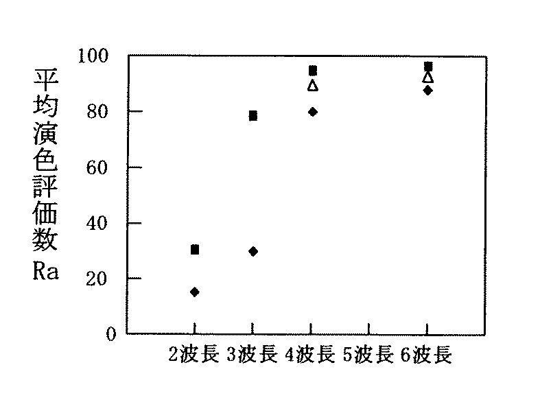
ここで、図3に、LEDのピーク波長の数と平均演色評価数の関係を示す。図3に示した結果は、本願発明者の実験および上記公報に示された値によるものである。
【0042】
図3から、LEDのピーク波長が増えるごとに、平均演色評価数が高まることが理解できる。それだけでなく、6波長域発光形光源でなくとも、4波長発光形光源で、十分に優れた演色性を示す光源が実現可能であることもわかる。すなわち、現実に存在する高効率LEDを用いた3波長域発光形のLED光源では、突破できなかった高い平均演色評価数を示す光源を4波長発光形光源で実現することができる。詳しく述べると、CIE(国際照明委員会)の演色性区分で言う演色性グループ1A(Ra≧90)であり、厳密な演色性が必要な用途に十分使用可能である光源を、4波長発光形光源で実現することができる。したがって、従来必要と言われていた6波長域発光形という多量の種類のLEDを用いなくとも良いことがわかった。図3に示した結果から理解できるように、4波長域発光形が現状のLEDを高効率かつ高演色(Raが90以上)に用いる際の最小条件のLEDの発光ピーク数の条件となる。
【0043】
以下、図面を参照しながら、本発明による実施の形態を説明する。以下の図面においては、説明の簡潔化のため、実質的に同一の機能を有する構成要素を同一の参照符号で示す。なお、本発明は以下の実施形態に限定されない。
(実施形態1)
図4から図6を参照しながら、本発明による実施形態1にかかる照明光源を説明する。図4は、本実施形態にかかるLED照明光源の構成を模式的に示しており、図5は、その照明光源の分光分布を模式的に示している。
【0044】
図4に示した照明光源は、4種のLED(11、12、13、14)を含む照明光源である。具体的には、本実施形態の照明光源は、青色を発光する青色LED11と、青緑色を発光する青緑色LED12と、橙色を発光する橙色LED13と、赤色を発光する赤色LED14から構成されている。
【0045】
青色LED11および青緑色LED12は、例えば、GaN系(GaNだけでなく、InGaN、AlGaN、AlInGaNも含む。すなわち、一般式IniGajAlkN、ただし、0≦i、0<j、0≦k、i+j+k=1)のLEDである。橙色LED13および赤色LED14は、例えば、AlInGaP系、GaAsP系、または、GaAlAs系のLEDである。これらのLEDは、市販品を用いることが可能である。
【0046】
なお、青色LED11および青緑色LED12は、GaN系のLEDだけでなく、ZnO系またはZnSe系のLEDを用いてもよい。ZnO系LEDとは、酸化銅やそのほかいくつかの金属酸化物でp型を作製し、そして、n型を酸化亜鉛で作製して、p−n結合を形成した発光ダイオードである。ZnO系LEDでは、混入する物質を変えることにより、例えば、380nm程度から500nm程度まで波長を自由に設定することができる。さらに、非線形光学結晶からなる素子によって赤色レーザダイオードの発光を例えば青色の発光に変換して発光する発光素子を、青色LED11および青緑色LED12として用いてもよい。つまり、非線形光学結晶からなる素子と、赤色レーザダイオードとを含む発光素子によって、青色LED11および青緑色LED12を構成してもよい。この非線形光学結晶からなる素子は、例えばリチウムニオブなどから構成されており、SHG(second harmonic generation)素子と呼ばれ、赤色レーザの波長を例えば半分の波長に変換することができる。
【0047】
本実施形態では、LED(11〜14)は、リードフレーム20の一部として形成された例えば皿状(またはカップ状)の台座21上に配置されている。LEDの下端(下部端子)は、台座21に接触するように配置され、LEDの上端(上部端子)は、ボンディングワイヤ22を介してリード23に電気的に接続されている。
【0048】
なお、本実施形態では、LED(11〜14)の上下に、LEDの電極となるアノードとカソードとを設けた例を示したが、これに限定されず、アノードとカソードをLEDの片面に設けた構成にしてもよい。リードフレーム20の構成も例示であり、台座21に2種以上のLEDを配置させた構成にしてもよいし、各リードフレーム20を電気的に接続するような構成にしてもよい。また、LEDをワイヤーボンディングして電気的接続を行っているが、これに限らず、LEDをフリップチップ実装してもよい。この場合には、ボンディングワイヤ22が存在しない構成にすることができる。リードフレーム20は、不図示の外部回路(例えば点灯回路)に電気的に接続されており、リードフレーム20に電力を供給して、LED(11〜14)を動作させると、図5に示すような発光分布を有する照明光を得ることができる。
【0049】
図5に示すように、本実施形態にかかる照明光源による分光分布は、青色LED11、青緑色LED12、橙色LED13、赤色LED14の発光ピークを有する。青色LED11は、420〜470nmに発光ピークを有し、青緑色LED12は、500〜550nmに発光ピークを有し、橙色LED13は、570〜600nmに発光ピークを有し、そして、赤色LED14は、610〜660nmに発光ピークを有している。これら4種のLED11〜14の組み合わせによって、高効率で演色性の高い(平均演色評価数80以上、さらには90以上)のLED照明光源を実現することが可能となる。より好適には、青色LED11は、450〜470nmに発光ピークを有し、青緑色LED12は、510〜540nmに発光ピークを有し、橙色LED13は、580〜600nmに発光ピークを有し、そして、赤色LED14は、625〜650nmに発光ピークを有している。
【0050】
図1に示したLEDと発光ピーク波長毎の効率との関係から理解できるように、LEDは、短波長側でGaN系の発光材料の発光効率が高く、長波長側ではAlInGaP系の発光材料の発光効率が高い。そして、約530〜575nmの発光帯域(緑色)においては、高効率なLEDは実現されていない。したがって、現実に高効率かつ高演色なLED照明光源を実現する上では、本実施形態の構成は大きな意義を含んでいる。
【0051】
また、GaN系発光材料から構成されたLEDを製造するという生産・製造上の観点からしても、大きな意義がある。すなわち、発光ピークが530nmを超えるLEDについては生産性が悪いため、発光ピークが530nm以下のLEDを用いて、Ra90以上の非常に高い平均演色評価数の照明光源を実現できることは、生産性が悪いものを使わなくてよいことになる。したがって、生産・製造上におけるメリットが非常に大きい。
【0052】
さらに、単に高演色を狙うためだけであれば、組み合わせる発光光色を増加させればよいが、実際には、その制御が複雑化するため、本実施形態のように、演色性を高める上で最小限の発光光色の組み合わせである4種のLEDを用いて照明光源を構成することもまた大きな意義を含んでいる。 本実施形態におけるLED11〜14のそれぞれの発光ピークは、単に、理論モデル(例えば、発光スペクトルをガウシアン分布型と仮定したモデル、非対称ガウシアン分布型と仮定したモデル)によるシミュレーションの結果から算出された想定ピークとは異なるものである。なお、LED11〜14の発光ピークの好適な組み合わせについては後述する。
【0053】
図6(a)および(b)は、本実施形態にかかる照明光源の分光分布の好適な例を示している。図6(a)は、相関色温度が比較的低い場合(2800K)の例であり、図6(b)は、相関色温度が比較的高い場合(6500K)の例である。図6に示した分光分布は、青色LED11、青緑色LED12、橙色LED13および赤色LED14の各発光ピークが、455nm、530nm、585nmおよび625nmの組み合わせのものである。
【0054】
図6(a)に示した例の平均演色評価数Raは93であり、図6(b)に示した例の平均演色評価数Raは95であった。いずれも、CIE(国際照明委員会)の演色性区分で言う演色性グループ1A(Ra≧90)である。すなわち、厳密な演色性が必要な用途(例えば、美術館用)に十分使用可能であり、両者とも、同じ4種のLED(11〜14)の発光比率(光束比)を調整するだけで、相関色温度が比較的低い場合でも高い場合でも、Raが90以上の優れた演色性を示す照明光源を実現することができる。
【0055】
図6に示したような優れた演色性を示すLED(11〜14)の組み合わせを見つけるために、本願発明者は、青、青緑、橙、赤の発光色を有する4種のLED(11〜14)をピーク波長5nm毎にマトリクス状に組み合わせ、各種演色の計算を行った。その結果、相関色温度が約3000Kから6500K近傍において、全ての相関色温度で同一の発光ピークを有しながら、優れた演色性を示す組み合わせは、下記表1に示すようなものであった。
【0056】
【表1】
なお、表1中の「Ga」および「Ga4」の詳細については、実施形態2にて後述するが、簡単に説明すると、「Ga」は、平均演色評価数計算用の試験色(R1〜R8)で構成される色域面積比であり、「Ga4」は、特殊演色評価数計算用の試験色(R9〜R12)で構成される色域面積比である。
【0058】
表1から理解できるように、およそ455nm、525nm、580nm、625nm近傍にピーク発光波長を有するLED(11〜14)を組み合わせれば、同一のLEDの組み合わせでその発光比率(光束比)を変化させるだけで、全ての実用的相関色温度中でRaが95に近い高演色な照明光源が実現することができる。実際のLEDの発光ピークの製造バラツキを考えれば、上記組み合わせの各ピーク発光波長の前後10nmあたりが現実的な最適点といえる。すなわち、455nm、525nm、580nm、625nmの組み合わせ、およびその各発光ピーク波長を僅かにずらした場合(例えば、±5〜10nm程度)の組み合わせの構成にて、高演色な照明光源を実現することができる。
【0059】
一般電球の平均演色評価数Raが100であるところ、本実施形態の照明光源のRaが95に近いものである。それゆえ、演色性の観点からみても、一般電球との置き換えが十分可能である。また、本実施形態では、発光効率の良いLED(11〜14)から照明光源を構成しているので、一般電球と比較して、発光効率に優れた照明光源を提供することができる。
【0060】
加えて、照明用に使用可能な相関色温度範囲においてRa=90以上の光源が実現でき、さらに、これらが全て同じ発光ピークを持つLEDの発光強度の調整だけで可能であることを示している点は、工業的な量産を前提とした場合、特定の発光ピークを持つLEDを大量生産(マスプロダクション)すればよいことを意味している。それゆえ、本実施形態の照明光源は、量産効果を上げるに極めて効果的な構成を有しているとともに、コスト低減に適した構成を有している。
【0061】
なお、Ra90以上の高演色を得るために、各種相関色温度のLED照明光源をLED11〜14にて構成する場合、455nm、525nm、580nm、625nmの組み合わせによるものに限らず、製造上のバラツキや、点灯中の色シフトも考慮して、450〜470nm、510〜540nm、580〜600nm、625〜650nmのそれぞれの範囲に各LEDの発光ピークが有するようにすればよい。
(実施形態2)
本実施形態では、青色LED11、青緑色LED12、橙色LED13、赤色LED14との組み合わせの最適化ついて説明する。上記実施形態1によれば、4種のLED(11〜14)を用いているので、上述したように、3種のLEDを用いた従来の照明光源よりも色再現性に優れたものを実現することができる。しかし、LEDから構成した照明光源の色再現性を評価する上で、色再現性の評価方法が問題となる。以下、この問題を説明する。
【0062】
従来から照明用光源として使用されている蛍光ランプ、電球、およびHID光源の発光に比べて、LEDの発光は、色を非常に鮮やかに見せるという傾向を有しているが、従来の平均演色評価数や特殊演色評価数だけの評価は、LEDを光源としたときの演色性の特徴を十分捉えきれない。LEDの発光が色を非常に鮮やかに見せるのは、LEDを照明に用いる際に特徴的な事象であり、半値幅の狭い狭帯域で、かつ、副発光波長のない高色純度の分光分布を有するというLEDの特徴に起因するものである。
【0063】
実施形態1の照明光源は、図5などに示すようにLED(11〜14)の半値幅の狭い発光を有している。それゆえ、蛍光ランプなどの光源と比べて、色を非常に鮮やかに見せることが可能である。本願発明者は、多数の実験・検討の下、LED照明光源にとって好適な分光分布を導きだすことに成功した。以下、本願発明者が行ったLED照明光源についての色再現性の最適化手法をまず説明し、その後、LED照明光源が優れた色再現性を示すのに最適な分光分布の例を説明する。
【0064】
まず、従来の演色性評価数による評価の問題を説明する。従来の演色性評価数は、評価する光源と同等の相関色温度を有する合成昼光や黒体放射などの基準光源での各種演色評価色票の色再現を100とおいた場合に、評価したい評価光源での各種演色評価色票の色再現が、当該基準光源での色再現とどれだけずれているかを評価し指標化するものである。それゆえ、評価光源での演色と基準光源での演色が一致した場合が最も評価が高くなる。評価色票が基準光源での演色よりもくすんで見え、その結果、好ましくなく見える場合は当然演色評価は低くなるが、逆に、評価色票が基準光源での演色よりも鮮やかに見え、その結果、好ましく見える場合もまた演色評価は低くなってしまう。つまり、より鮮やかに見えたり、色が目立って見えたりする場合にも、演色評価が低くなるという問題を有している。
【0065】
今日、日常生活において人間を取りまく物は、木や石などの中彩度の自然物ばかりでなく、鮮やかな青や黄色等のような人工的に鮮やかな着色がなされた色を持った工業製品で満ちあふれている。このため、評価色票が基準光源での演色よりも鮮やかに見える場合に、その光源に対して、低い評価を与えることは必ずしも適切な評価とはいえない。そこで、本願発明者は、LED照明光源の特徴を生かすべく、LED照明光源の分光分布の最適化を行った。以下、本願発明者が行った最適化手法を説明する。
【0066】
光源の演色性評価手法は、国際的な整合を持っており、日本ではJIS Z8726に開示されている。この中で、国際規格では規定されていないものの、「演色評価数による以外の演色性の評価法」として色域面積比による方法が、一般にオーソライズされた方法として示されている。この方法は、平均演色評価数計算用の試験色(R1〜R8)で構成される色域面積の比で評価する方法である。より詳細に説明すると、平均演色評価数の算出に用いられるR1からR8までの色度座標を用いるものであり、基準光源によって演色される色度座標上の8点を結んだときの色度座標上の面積と、評価光源によって演色される色度座標上の8点を結んだときの色度座標上の面積との比を求め、それを色域面積比Gaとする評価手法である。
【0067】
この評価手法によれば、Gaが100より小さいときには、彩度が減った色の見えとなるため、くすんで見える傾向にあり、一方、Gaが100より大きいときには、彩度が増した色の見えとなるため、鮮やかに見える傾向にある。このように、基準光源との色再現のずれによる評価でなく、色域面積比による評価を用いると、鮮やかに見える場合において、Raが低くなっても、好ましく見える傾向を示す評価を得ることができる。この評価手法は、LEDの特徴である鮮やかな演色を評価する上で、有効な評価指標であるように思える。しかし、この指標のみを使用した場合、Gaを高めると良い評価になるものの、同様の評価試験色を用いて評価したRaは低下してしまい、基準光源との色再現のずれによる違和感が大きくなってしまう。つまり、Gaの指標のみを使用した場合、Raの指標との整合性がとれなくなってしまう。
【0068】
そこで、本願発明者は、鮮やかな赤・黄・緑・青についての特殊演色評価数であるR9からR12を用いた色域面積比を、新たな評価指標として導入した。この評価指標による評価方法を説明すると、上述したR1からR8の評価試験色を用いたGaと同様のJISZ8726に示される計算手法に乗っ取って、R1からR8の評価試験色の代わりにR9からR12を用いて色域面積比を求める方法である。以下、本明細書において、特殊演色評価数R9〜R12による色域面積比を「Ga4」と呼ぶこととする。
【0069】
本来、R1からR8は、自然な物の微妙な見えの違いを評価するために選定されたものであり、中彩度の試験色である。これに対して、R9からR12は、本来鮮やかなものの見えを評価するために選定された評価色票である。このため、Ga4を使用することによって、鮮やかに見せたい物が鮮やかに見えているかということを抽出して正確に評価することが可能になる。つまり、中彩度の微妙で正確な色の見えが要求される物に対する見えについては、GaとRaが100に近くなるような自然の物の色に忠実な色再現を行い、かつ、鮮やかな色再現を行いたい物に対する見えについては、Ga4が高くなるような色鮮やかな色再現を行うことが、色再現の最適化となる。このような最適化を行うと、色の彩度のコントラストが高くメリハリを利かせつつ、より自然な色再現を行わせることができる。
【0070】
本願発明者は、上記実施形態1のLED照明光源に対して、最適化処理を行い、次のような知見を得た。
【0071】
(1)LED11から14のそれぞれの発光ピークが、420〜470nm、500〜550nm、570〜600nmおよび610〜660nmの場合に平均演色評価数Raを高めることができ、450〜470nm、510〜540nm、580〜600nm、625〜650nmの場合にすると、さらにRaを高めることができる。
【0072】
(2)相関色温度が比較的低く(5000K未満)、演色性評価の基準光源が黒体放射の場合、図7(a)に示すように、分光分布で比較して、ピーク波長の短いものから順に、すなわち、LED11、12、13、14の順に、LEDのピーク強度を高めた発光分布にすると、Raを高めながらGa4を高め、かつ、GaよりもGa4を高くすることができる。つまり、この範囲であれば、微妙で厳密な色再現が望まれる中彩度の色については忠実に色再現することができ、高彩度の色については、鮮やかに色再現を行うことができる。Raを高める観点から、LED11〜14のピーク波長は、それぞれ、450〜470nm、510〜540nm、580〜600nm、625〜650nmの範囲内にすることが好適である。
【0073】
(3)相関色温度が比較的高く(5000K以上)、演色性評価の基準光源が合成昼光の場合、図7(b)に示すように、分光分布で比較して、ピーク波長の最も短い青色LED11と、最も長い赤色LED14との両者に挟まれる青緑色LED12、橙色LED13に対して、青色LED11は、青緑色LED12よりもピーク強度を高くし、赤色LED14は、橙色LED13よりもピーク強度を高くした発光分布にすると、Raを高めながらGa4を高め、かつ、GaよりもGa4を高くすることができる。つまり、この範囲であれば、微妙で厳密な色再現が望まれる中彩度の色については忠実に色再現することができ、高彩度の色については、鮮やかに色再現を行うことができる。上記(2)の相関色温度が比較的低い場合と同様に、Raを高める観点から、この場合でも、LED11〜14のピーク波長は、それぞれ、450〜470nm、510〜540nm、580〜600nm、625〜650nmの範囲内にすることが好適である。
【0074】
色再現の最適化が行われたLED照明光源の例を、図8から図10ならびに表2から表4に示す。
【0075】
図8(a)は、相関色温度が低いものの代表として3000Kの場合について最適化を行ったLED照明光源の分光分布の一例を示している。3000Kは、常用される照明光源において相関色温度の下限に近いレベルである。3000Kの場合、Raの計算時においては比較する基準光源は黒体放射である。この例におけるLED11、12、13、14の発光ピーク波長は、それぞれ、455nm、525nm、580nm、625nmであり、そして、それらの光束比は、それぞれ、1.53、37.64、34.83、26.00である。
【0076】
図8(b)は、図8(a)に示した分光分布を持つLED照明光源についてのGaによる色域面積比を示すグラフであり、そして、図8(c)は、Ga4による色域面積比を示すグラフである。下記表1には、上記条件に加えて、図8についてのLED照明光源の光色の色度値(x,y)、Duv、演色性(Ra、R1〜R15)、色域面積比もあわせて示している。
【0077】
【表2】
図8(a)と同様に、図9(a)は、相関色温度が中位のものの代表として5000Kの場合について最適化を行ったLED照明光源の分光分布の一例を示している。5000Kは、Raの計算時においては比較する基準光源が黒体放射から、合成昼光に切り替わるポイントである。この例におけるLED11、12、13、14の発光ピーク波長は、それぞれ、455nm、525nm、580nm、625nmであり、そして、それらの光束比は、それぞれ、3.54、47.25、30.86、18.34である。
【0079】
図9(b)および(c)は、それぞれ、GaおよびGa4の色域面積比を示すグラフである。表2と同様に、下記表3には、上記条件に加えて、図9についてのLED照明光源の光色の色度値(x,y)、Duv、演色性(Ra、R1〜R15)、色域面積比もあわせて示している。
【0080】
【表3】
また、図10(a)は、相関色温度が6700Kの場合について最適化を行ったLED照明光源の分光分布の一例を示している。6700Kは、常用される照明光源において相関色温度の上限に近いレベルである。6700Kの場合、Raの計算時においては比較する基準光源は合成昼光である。この例におけるLED11、12、13、14の発光ピーク波長は、それぞれ、455nm、525nm、580nm、625nmであり、そして、それらの光束比は、それぞれ、4.80、50.02、29.46、15.72である。
【0082】
表2と同様に、下記表4には、上記条件に加えて、図10についてのLED照明光源の光色の色度値(x,y)、Duv、演色性(Ra、R1〜R15)、色域面積比もあわせて示している。
【0083】
【表4】
色再現の最適化が行われていないLED照明光源の例を、参考として、図11および表5に示す。
【0085】
図11(a)は、図9(a)と同様に、相関色温度が中位のものの代表として5000Kの場合についてのLED照明光源の分光分布の一例を示しており、基準光源は合成昼光である。この例におけるLED11、12、13、14の発光ピーク波長は、それぞれ、445nm、515nm、580nm、630nmであり、そして、それらの光束比は、それぞれ、2.01、43.06、39.10、15.82である。
【0086】
図11(b)および(c)は、それぞれ、GaおよびGa4の色域面積比を示すグラフである。下記表5には、上記条件に加えて、図11についてのLED照明光源の光色の色度値(x,y)、Duv、演色性(Ra、R1〜R15)、色域面積比もあわせて示している。
【0087】
【表5】
本願発明者は、本実施形態で行った色再現の最適化にあたり、各種相関色温度で波長5nmおきに現実のLEDの分光分布をマトリクス的に組み合わせ、かつ数理計画法(シンプレックス法)によりその最適値を検証した。また、色再現の最適化に際しては、同様のRa、Ga、Ga4を示した場合においては、図8(a)等のように各種評価色票の色度をプロットし、原点に対して、回転方向(例えば、時計周り)への試験色票の色ズレが小さいものをより選択するという条件を加えたので、色相方向への好適でない色ズレは最小に抑えられている。図8から図11および表2から表5の結果をふまえて、上述した本願発明者による知見をさらに詳述する。
【0089】
1.青色LED11の発光ピークを450nmより小さくすると、青の試験色が鮮やかに再現されすぎてしまい、GaやGa4が高くなりRaの低下が見られた。また逆に、470nmより大きく設定した場合は、青の試験色がくすんで再現されず、GaやGa4が低くなりRaの低下が見られた。加えて、青緑発光との発光ピークの間隔が狭くなりすぎ、青と青緑の色票間の色相方向の色ずれが大きくなった。この結果から、青と青緑の発光ピークの間隔を60nmから70nm程度にすることが好ましいことがわかった。そして、これがRaを高めるポイントとなる。
【0090】
ただし、各種色温度を共通に同じLEDを使用して、その発光強度を変化させるのみで高演色光源を実現することを考えずに、Raを高めることだけを考えれば、青色LED11についての当該範囲は緩和され、420nmから470nmとなる。
【0091】
2.青緑色LED12の発光ピークを、比較的長波長側の530nm近傍にすると、Raを高める上で有利に働く。ただし、530以上、例えば、540nmや550nmにまで発光ピークを長波長側にすると、Raは低下する傾向にあることがわかった。加えて、青緑色LED12の発光波長が540nmを超えると、GaN系に代表されるLEDの工業的な歩留まりが低下する。また、青色LED11と青緑色LED12との発光ピークの間隔は、60nmから70nm程度あることが好ましいことから、青緑色LED12の発光ピークの下限は、少なくとも500nm、より高演色を望む場合には510nmにすることが好ましい。ここで、明所視での効率だけでなく、薄明視や暗所視での実効的な明るさ感の向上を指向する場合は、人間の桿体視細胞の受光感度のピークが約505nmにあるので、積極的に、この波長の近傍に青緑色LED12の発光ピークを選択しても良い。
【0092】
3.橙色LED13の発光ピークを、比較的短波長側の570nmから600nmの近傍にすると、Raを高める上で有利に働く。これよりも下回る波長の発光ピークにすると、Raは低下する傾向にあることがわかった。橙色LED13の発光波長が580nmを下回り始めると、AlInGaP系に代表されるLEDの工業的な生産性が低下するのであるが、570nmを下回るとそれがさらに低下する。また、橙色LED13の発光ピークが600nmを超えると、青緑色LED12と橙色LED13との発光ピークの間隔が広がりすぎ、そして、橙色LED13と赤色LED14との発光ピークの間隔が狭くなりすぎてしまうため、GaやGa4の分布が色相方向に歪んでしまい、その結果、Raが低下してしまう。
【0093】
4.赤色LED14の発光ピークを、620nmから630nmの近傍にすると、Raを高める上で有利に働く。赤色LED14の発光ピークの下限は、緩やかにみれば610nmであり、厳しくみれば、620〜630nmの中間の625nmである。650nmより大きく設定した場合、赤の試験色が鮮やかに再現されすぎてしまい、GaやGa4が高くなりRaの低下が見られた。また逆に、625nmより小さく設定した場合には、赤の試験色がくすんで再現されず、GaやGa4が低くなりRaの低下が見られた。
【0094】
ただし、各種色温度を共通に同じLEDを使用して、その発光強度を変化させるのみで高演色光源を実現することを考えずに、Raを高めることだけを考えれば、この範囲は緩和され610nmから660nmとなる。ここで、特に、基準光源が黒体放射となる比較的低色温度な光源を実現する場合のみを考えると、最適解は特異的にずれることがわかり、上記赤発LED14のピーク波長の範囲中でも630nmを超える長波長側に発光ピークを持ってきた方がRaが高まることが見出された。なお、この現象は、基準光源が黒体放射となる低色温度光源を目標とした場合に顕著であった。
【0095】
図11および表5から理解できるように、この例では、Raは、90を超える良好な値を示しているものの、橙色LED13の発光ピークが赤色LED14の発光ピークより高いため、Ga4の値は、Gaの値より小さくなっている。つまり、Gaの値が高くなりすぎており、微妙で厳密な色再現が望まれる中彩度の色についての忠実な色再現性が少し悪くなる。なお、より色彩が鮮やかに見せることに主眼をおく場合には、Gaの値が高くてもよく、そして、Raを必要以上に高くしなくてもよいため、図11に示したようなものも利用できることになる。したがって、そのようなLED照明光源を実現できる範囲は、上述した最適化の範囲よりもさらに広がることになる。
(実施形態3)
図12を参照しながら、本発明による実施形態3にかかる照明光源を説明する。図12は、本実施形態にかかるLED照明光源の分光分布を模式的に示している。
【0096】
本実施形態のLED照明光源は、上記実施形態1および2における青色LED11、青緑色LED12、橙色LED13、赤色LED14に加えて、LEDからの発光によって励起して発光する蛍光体15を備えている。蛍光体15は、LED11〜14の発光スペクトルと比較すると、ブロードな発光スペクトルを有しているので、蛍光体15によって、LED11〜14の混色を良好にすることができる。また、LED11〜14の周囲に、蛍光体15を設けておくと、蛍光体15の散乱によって、LED11〜14の混色を良好にすることが可能である。
【0097】
本実施形態における蛍光体15は、青色LED11からの発光によって励起され、緑色から黄色の範囲のいずれかの色を発光する蛍光体であり、例えば、黄色発光蛍光体または緑色発光蛍光体である。青色LED11に限らず、青緑色LED12などの発光によって励起させてもよい。蛍光体15としては、YAG蛍光体、または、Mn発光中心を有する無機系蛍光体を用いることができる。また、無機系蛍光体に限らず、有機系蛍光体を用いてもよい。
【0098】
図12からわかるように、蛍光体15を設けることより、LED(11〜14)に不足している発光波長のスペクトルを補うことが可能となる。蛍光体15は、半値幅の広いブロードな発光スペクトルを有しており、本実施形態の蛍光体15の半値幅は、LED11〜14(例えば、11)の半値幅よりも広く、蛍光体15は、50nm以上の広帯域な発光スペクトルを有している。
【0099】
本実施形態の照明光源は、蛍光体15を有しているので、各光色のLED(11〜14)の点灯条件が変化した場合でも発光光色の変動しないように、光色変動を抑制することができる。つまり、LEDは狭帯域発光なスペクトルを有するため、各光色のLED(11〜14)の点灯条件の変化に対し発光光色の変動が大きくなり、その結果、制御が困難であるが、広帯域発光の蛍光体15の発光とLEDの発光とを組み合わせることにより、各光色のLEDの点灯条件の変化に対し変動し得る発光光色の変化を抑制することができる。
(実施形態4)
図13および図14を参照しながら、本発明による実施形態4にかかる照明光源を説明する。図13は、本実施形態にかかるLED照明光源の回路構成を模式的に示している。
【0100】
上記実施形態1〜3のLED照明光源は、図13に示した回路構成にすることよって、光色可変光源にすることが可能である。
【0101】
図13に示した回路51は、青色LED11と、青緑色LED12と、橙色LED13と、赤色LED14のそれぞれの発光強度を調節する発光強度調節手段(発光強度調節器)56を備えており、各色のLEDの発光強度を調節する機能を備えている。すなわち、発光強度調節手段56によって、各LED(11〜14)の発光強度比(光束比)を調節することができる。本実施形態では、発光強度調節手段56として、可変抵抗を用いている。
【0102】
発光強度調節手段56としては、各LEDへの供給電力を変化させる手段をとり得るものであればよい。したがって、可変抵抗に限定されず、固定抵抗を切り替える手段、ラダー抵抗を使用する手段、周波数制御による手段、時分周点灯による手段、電源から見て負荷となるLEDの連結個数を変える手段、または、結線法を切り替える手段などを用いることができる。
【0103】
図14に示した回路構成は、図13に示したものの改変例である。図14に示すように、青色LED11と橙色LED12とを一組とし、青緑色LED12と赤色LED14とを一組として制御すれば、発光強度調節手段(発光強度調節器)の数を減らすことができ、回路構成をシンプルにすることが可能となる。それぞれの組み合わせは、LEDが互いに補色になるような組み合わせにしてある。この構成の場合、LED側から見た第一段の発光強度調節手段57は何れもGaN系LEDとAlInGaP系LEDとの比較器の動作を伴っており、この動作は、LED側から見て第二段の発光強度調節手段58によって、さらに比較調整される。これにより、GaN系LEDとAlInGaP系LEDとの比較が2つと、それぞれの比較動作の比較が1つとを含む形に回路動作を分離することが可能である。したがって、本発明のLED照明光源の動作を確実かつ簡略なものにすることができる。このような動作を行う回路は、多様なものが考えられるが、比較器(コンパレータ)を用いたフィードバック回路などがその代表である。
【0104】
本実施形態の構成によれば、LED(11〜14)の強度比を調節することができるため、任意の光色を発光させることができる。また、各LEDの発光強度を可変できるので、この構成によって、照明光源の明るさも簡便に調節することができる。
【0105】
なお、各発光光色のLED11〜14を個別の素子としてした後、それを組み合わせて照明光源を構成する場合に限らず、LED11〜14を一つのLED素子内に配置した構成にしてもよい。LED11〜14を一体に素子構成した場合、混色ムラを小さくすることが可能となる。すなわち、発光源となる各々の光色のLED11〜14を個別の素子として構成して、空間的に離れた箇所で発光させた場合と比較して、LED11〜14を一体に素子構成した場合の方が混色ムラを小さくできる。
【0106】
一方、LED11〜14を個別の素子として作製した後に、それらの素子を1つのユニットにクラスタにしてもよい。この構成の場合、各々のLED素子設計を個別に最適設計することができるという利点がある。また、各々のLED素子の良品を選別して1つのユニットにクラスタすることができるために、工業的な歩留まりを向上させることが可能となる。さらに、各発光光色のLEDの出力光束が異なる場合でも、各々のLEDを個別の素子として構成したことにより、そのクラスタ数の比率を任意に設定することができるので、ランプ設計の自由度を高くすることができる。その結果、LED11〜14の各出力光束が異なる場合でも、良好な特性を示す照明光源を簡便に提供することができる。言い換えると、1つの素子内に各発光色のLED(11〜14)が一定の比率で予め組み込まれている素子をクラスタするよりも、そのような構成の方がランプ設計の自由度を上げることができる。
(実施形態5)
図15を参照しながら、本発明による実施形態5にかかる照明光源を説明する。図15は、本実施形態にかかるLED照明光源61の構成を模式的に示している。
【0107】
上記実施形態1〜4におけるLED照明光源は、図15に示すように、LED(11〜14)に電力を供給する電力供給器64と組み合わせてユニット(ランプユニットまたは照明装置)にすることができる。
【0108】
本実施形態のランプユニット61は、上記実施形態のLED11〜14のうちの1つまたは2以上ないし全てから構成されたLED62と、LED62から発する光を反射する反射板63と、LED62に電力を供給する電力供給器64と、電力供給器64に連結されている口金65とを備えている。
【0109】
反射板63の底面には、単数または複数のLED62を配置することができ、例えば10個〜200個程度配置することができる。さらに、反射板63がLED62と熱的に結合されていると、反射板63がヒートシンクの役割を果たすため、LED62の放熱性の向上に寄与することが可能となる。その結果、LED62をより長寿命化させて使用することができる。反射板62としては、拡散反射板(例えば、白色反射板)や鏡面反射板(反射鏡)を使用することができる。
【0110】
LED62を約60個設けたランプユニット61の場合、ビーム光束(ビーム角内に含まれる光束)は60lm、ランプ寿命は10000時間、そして発光効率は約30〜50lm/Wとなることを本願発明者は確認した。この特性は、従来のハロゲン電球とダイクロイックミラーとを組み合わせた従来のランプユニットの特性(ビーム光束:約60lm、寿命:2000時間、発光効率:約15lm/W)と比較すると、非常に優れていることがわかる。また、ランプユニット61に取り付けられるLED62は、半導体素子であるので取り扱いが容易であるという利点もある。
【0111】
また、従来のいわゆる青・緑・赤の3波長を組み合わせた同種のランプユニットでは平均演色評価数Raが各種相関色温度(3000K、5000Kなど)で20そこそこであるのに対し、青・青緑・橙・赤の4波長域のLEDを組み合わせた本実施形態のランプユニット61では、平均演色評価数Raを各種相関色温度において約95とすることが可能であった。さらに、上記実施形態4の構成を採用して、本実施形態のランプユニット61を、光色可変可能なものとして提供することもできる。この場合、例えば、図13に示した発光強度調節手段(発光強度調節器)51を電力供給器64に設けるようにすればよい。
【0112】
さらに、電力供給器64とLED62とを、断熱材などの断熱手段で熱的に遮蔽した構成にすれば、電力供給器64の発熱がLED62に伝わる割合を減少させることができる。それにより、LEDの加熱が抑制することができる。
【0113】
本実施形態において、電力供給器64には、例えばAC/DC変換器などを設けるようにすることもできる。図15に示した例では、電力供給器64に、光色可変スイッチ66と明るさ可変ダイヤル67とが取り付けられており、これらのダイヤル操作で照明の光色と明るさとのそれぞれを調節できるように構成している。
【0114】
本実施形態では、反射板63および口金65付きのランプユニット61を用いて説明したが、これに限定されない。ランプユニット61の反射板63および口金65は各種用途に応じて設けたり、設けなかったりすることができる。また、60個程度のLED62を1ユニットとしてその1ユニットを1つの光源として使用する構成にすることも可能である。また、その1ユニットを複数用いる構成にしてもよい。図15に示したLED62は、スルーホール型の砲弾型素子であるが、素子の形状にはとらわれず、表面実装型のチップ型素子であってもよいし、LEDのベアチップを直接基板上に実装したものであってもかまわない。
(実施形態6)
図16を参照しながら、本発明による実施形態6にかかる照明光源を説明する。
【0115】
上記実施形態1〜5におけるLED照明光源は、放熱性の基板上にLEDを実装された形態にし、これに電力を供給する電力供給器と組み合わせたユニットの構成にすることもできる。図16は、本実施形態にかかるランプユニット(LED照明光源)71の構成を模式的に示している。
【0116】
本実施形態のランプユニット71は、上記実施形態のLED11〜14のうちの1つまたは2以上ないし全てから構成されたLED72と、LED72が実装される放熱性基板73と、放熱性基板の熱を放散するヒートシンク74と、LED72から発する光を反射する反射板75と、LED72に電力を供給する電力供給器76を備えている。
【0117】
放熱性基板73には、単数または複数のLED72を配置することができ、例えば10個〜200個程度配置することができる。本実施形態においてLED72は、ベアチップの形態である。LED72がヒートシンク74と熱的に結合されていると、LED72の放熱性の向上に寄与することが可能となる。その結果、LED72をより長寿命化させて使用することができる。放熱性基板73としては、ガラスエポキシ基板、コンポジット基板、セラミック基板が適している。これらの基板が金属ベースを有している場合、より放熱性を向上させることができるため好ましい。また、これらの基板は多層基板であってもよい。
【0118】
反射板73としては、拡散反射板(例えば、白色反射板)や鏡面反射板(反射鏡)を使用することができる。また、反射板73を別途設けるのではなく放熱性基板表面を白色仕上げとして拡散反射板としたり、鏡面仕上げとして鏡面反射板(反射鏡)とすることも可能である。
(実施形態7)
図17を参照しながら、本発明による実施形態7にかかる照明光源を説明する。本実施形態では、青色LED11の発光部位と、橙色LED13の発光部位とが、一つのチップ内に設けられており、かつ、赤色LED14の発光部位と、青緑色LED12の発光部位とが、一つのチップ内に設けられている。この点が、上記実施形態1〜6と異なる。他の点においては、上記実施形態と同様であるので、説明の簡略化のため、上記実施形態と同様の点の説明は省略または簡略化する。なお、本実施形態の構成に対して、上記実施形態1〜6の構成を組み合わせることも可能である。
【0119】
本実施形態の照明光源では、青色LED11の発光層と、橙色LED13の発光層を一つのLEDベアチップとして一体構成し、青緑色LED12の発光層と、赤色LED14の発光層を一つのLEDチップとして一体構成している。このような構成の場合、通常4つの色のベアチップを並べる必要があったものが、2つのベアチップで済むことになる。一つのベアチップ内の両LEDは互いに補色関係にあり、かつ、両者の発光位置が一つのLEDベアチップ状で限りなく同一に近づくため、より混色に有利である。さらに、両者がより熱的に接合されているため両発光層間の温度が均一化され、両者を熱的に同一とみなせることができ、その結果、光出力に対する熱の影響のフィードバックコントロールが行いやすくなるという利点も得られる。
【0120】
また、青色発光と橙色発光とは、GaN系発光材料とAlInGaP系発光材料との組み合わせであり、青緑色発光と赤色発光もGaN系発光材料とAlInGaP系発光材料との組み合わせで形成できるため、一つに接合されたベアチップ各々の発光材料の組み合わせを同一にすることが可能となる。そのため、材料の組み合わせを同一にできることから、熱の影響のフィードバックコントロールがより行いやすくなっている。
【0121】
最初に、図17(a)〜(c)を参照しながら、2つの発光層を有するLEDベアチップを作製するプロセスを説明する。
【0122】
まず、図17(a)に示すように、LED成膜用の基板116上に、少なくともP型半導体層とN型半導体層と活性層とを含む第1のLED発光層111を形成する。
【0123】
次に、図17(b)に示すように、基板116を剥離して、第1のLED発光層111を得る。基板116の剥離は、基板116およびLED発光層の種類によって適宜選択すればよく、例えば、基板116の研磨、メカニカルな剥離、エッチングによる基板116の除去、熱ストレスによる剥離、レーザーやマイクロウェーブを利用した剥離などの手法が採用され得る。
【0124】
次に、図17(c)に示すように、他のLED発光層113が形成されている基板116’に、第1のLED発光層111を張り付けると、2つの発光色を発するLEDベアチップが得られる。このように、第1のLEDの発光層および他のLEDの各々またはいずれかを剥離した後、張り合わせて、一つのLEDベアチップにする。この例では、異種発光層の張り合わせを主体に説明しているが、勿論、同種材料同士の張り合わせも可能である。張り合わせにおいては、高真空を用いて行われる真空接合、接着剤を用いた接合(接着)、加圧を用いて行われる接合、加熱を用いて行われる接合などの手法の採用することができる。加えて、これらの手法を組み合わせて採用することも可能である。
【0125】
以下、図18から図21を参照しながら、張り合わせの組み合わせパターンを例示する。この張り合わせのバリエーションは多数存在するが、以下では、主なパターンを示す。なお、便宜上、青色LED11、青緑色LED12、橙色LED13および赤色LED14の発光層を、それぞれ、発光層111、112、113および114とする。これらのLED発光層の周囲に、上記実施形態3で示した蛍光体15を形成してもよい。
【0126】
図18(a)は、基板116が導電性である場合の両面電極構造の例を示している。この構造の場合、基板116を挟んで、上側の各発光層(111、112)の上面に1つの電極を設け、下側の各発光層(113、114)の下面に1つの電極を設ければよい。
【0127】
図18(b)は、発光ダイオード基板が非導電性である場合の片面電極構造の例を示している。この構造の場合、基板116を挟んで、上側の各発光層の上面に2つ、下側の各発光層の下面に2つの電極を設ければよい。
【0128】
図18(c)は、基板116が導電性である場合において、片面電極構造と両面電極構造との組み合わせた例である。この構造の場合、基板116を挟んで、上側の各発光層の上面に1つ、下側の各発光層の下面に2つの電極を設ければよい。
【0129】
図19(a)は、基板116が導電性である場合において、各基板116片側にLED発光層を積み上げた例である。この構造の場合、上側の各発光層の上面に1つ、各基板116の下面に1つの電極を設ければよい。
【0130】
図19(b)は、基板116が導電性である場合において、各基板116片側に、両面電極および片面電極のLED発光層を積み上げた例である。この構造の場合、各基板116の上面に1つ、下側の各LED発光層の下面に2つの電極を設ければよい。
【0131】
図19(c)は、基板116を挟んで、下側に短波長の発光を行うLED発光層(111、112)を配し、当該短波長の発光を行うLED発光層からの光で励起発光されるLED活性層(113’、114’)を上側に配した構造を示している。この構造の場合、LED発光層111、112のそれぞれの下面に2つの電極を設ければよい。
【0132】
図18および図19に示した構造は、多数の考えられる組み合わせの一例であり、各発光色のLED発光層の組み替えのバリエーションはもとより、図18(c)、図19(a)〜(c)に示した構造では、上下関係についての反転パターンもある。
【0133】
また、各々のLED発光層を基板116の片側または両側に積層するのではなく、同一基板116上に空間的に並置させた構造にすることも可能である。そのような構造の例を、図20および図21に示す。
【0134】
図20(a)は、各色のLED発光層(111〜114)を、1つの導電性基板116に形成した構造を示している。この構造の場合、基板116の下側に共通した一つの電極を設け、かつ、各LED発光層の上面に1つずつ電極を設ければよい。
【0135】
図20(b)は、各色のLED発光層を、1つの非導電性基板116に形成した構造を示している。この構造の場合、各LED発光層の上面に2つずつ電極を設ければよい。
【0136】
図20(c)は、図20(b)に示した構造の上下関係を反転させたパターンを示している。
【0137】
図21(a)は、各色のLED発光層(111〜114)を、1つの導電性基板116に形成した構造を示している。この構造の場合、基板116の下側に共通した一つの電極を設け、かつ、各LED発光層の上面に1つずつ電極を設けたものと、各LED発光層の上面に2つずつ電極を設けたものとを混在させている。
【0138】
図21(b)は、LED発光層をそのまま並置した構造を示している。この構造の場合、基板116が不要となるとともに、図14(c)に示した張り合わせプロセスを行わなくてもよい。
【0139】
図21(c)は、両面電極のLED発光層を2つそのまま積層した構造を示している。この構造の場合でも、基板116は不要となる。また、このコンセプトの場合、片面電極および両面電極のLED発光層を積層するバリエーションや、4つのLED発光層を積層するバリエーションもあり得る。
【0140】
図20および図21に示した構造も、多数の考えられる組み合わせの一例であり、各発光色のLED発光層の組み替えのバリエーションはもとより、図20(a)、図21(a)および(b)に示した構造の上下関係の反転パターンもある。
【0141】
なお、本実施形態で用いたLEDとして、DBR(Distributed Bragg Reflector)の構成を有するレーザダイオードや、Resonant Cavity発光ダイオードまたはNon-Resonant Cavity発光ダイオードを採用することが可能であり、さらには、VCSEL(Vertical Cavity Surface Emitting Laser)の構成を有するレーザダイオードを採用することも可能である。
【0142】
【発明の効果】
本発明によると、青色を発光する青色発光ダイオードと、青緑色を発光する青緑色発光ダイオードと、橙色を発光する橙色発光ダイオードと、赤色を発光する赤色発光ダイオードとの4種の発光ダイオードを含むので、最小構成要素の色数のLEDで、高効率かつ高演色性を示すLED照明光源を提供することができる。
【図面の簡単な説明】
【図1】LEDの発光ピーク波長毎の効率を模式的に示すグラフである。
【図2】(a)は、アシンメトリカルガウシアンの分光分布によってシミュレーションされた分光分布を示すグラフであり、(b)は、実測に基づいた分光分布を示すグラフである。
【図3】LEDのピーク波長の数と平均演色評価数Raとの関係を示すグラフである。
【図4】実施形態1にかかるLED照明光源の構成を模式的に示す図である。
【図5】実施形態1にかかるLED照明光源の分光分布を模式的に示すグラフである。
【図6】(a)は、相関色温度が比較的低い場合の分光分布を示すグラフであり、(b)は、相関色温度が比較的高い場合の分光分布を示すグラフである。
【図7】(a)は、相関色温度が比較的低い場合の好適な分光分布を示すモデルであり、(b)は、相関色温度が比較的高い場合の好適な分光分布を示すモデルである。
【図8】(a)は、3000Kの場合において最適化を行ったLED照明光源の分光分布を示すグラフである。(b)は、Gaによる色域面積比を示すグラフである。(c)は、Ga4による色域面積比を示すグラフである。
【図9】(a)は、5000Kの場合において最適化を行ったLED照明光源の分光分布を示すグラフである。(b)は、Gaによる色域面積比を示すグラフである。(c)は、Ga4による色域面積比を示すグラフである。
【図10】(a)は、6700Kの場合において最適化を行ったLED照明光源の分光分布を示すグラフである。(b)は、Gaによる色域面積比を示すグラフである。(c)は、Ga4による色域面積比を示すグラフである。
【図11】(a)は、5000Kの場合におけるLED照明光源の分光分布を示すグラフである。(b)は、Gaによる色域面積比を示すグラフである。(c)は、Ga4による色域面積比を示すグラフである。
【図12】実施形態3にかかるLED照明光源の分光分布を模式的に示すグラフである。
【図13】実施形態4にかかるLED照明光源の回路構成を模式的に示す図である。
【図14】実施形態4にかかるLED照明光源の回路構成を模式的に示す図である。
【図15】実施形態5にかかるLED照明光源(ランプユニット)61の構成を模式的に示す図である。
【図16】実施形態6にかかるLED照明光源(ランプユニット)71の構成を模式的に示す図である。
【図17】(a)〜(c)は、LEDベアチップの作製プロセスを説明するための工程断面図である。
【図18】(a)〜(c)は、実施形態7におけるLEDベアチップの断面構成を模式的に示す図である。
【図19】(a)〜(c)は、実施形態7におけるLEDベアチップの断面構成を模式的に示す図である。
【図20】(a)〜(c)は、実施形態7におけるLEDベアチップの断面構成を模式的に示す図である。
【図21】(a)〜(c)は、実施形態7におけるLEDベアチップの断面構成を模式的に示す図である。
【符号の説明】
11 青色LED
12 青緑色LED
13 橙色LED
14 赤色LED
15 蛍光体
20 リードフレーム
21 台座
22 ボンディングワイヤ
23 リード
51 回路
56 発光強度を調節する発光強度調節手段(発光強度調節器)
57 LED側から見た第一段の発光強度調節手段(発光強度調節器)
58 LED側から見た第二段の発光強度調節手段(発光強度調節器)
61、71 ランプユニット
62、72 LED
63 LEDから発する光を反射する反射板
64 電力供給器
65 口金
66 光色可変スイッチ
67 明るさ可変ダイヤル
73 放熱性基板
74 ヒートシンク
75 反射板
76 電力供給器
111、112、113、114 LED発光層
116 基板[0001]
BACKGROUND OF THE INVENTION
The present invention relates to an illumination light source including a light emitting diode.
[0002]
[Prior art]
A light-emitting diode (hereinafter, referred to as “LED”) is a semiconductor element that is small, efficient, and emits brightly colored light, and has high color purity due to its narrow spectral half-value width. In recent years, blue LEDs have been put into practical use, and as a result, three colors of red, green, and blue have been prepared, and it has been possible to emit white light using the LEDs.
[0003]
[Problems to be solved by the invention]
Conventionally, since LED has been mainly applied as a display element, there has not been much research and development in the case of using the LED as a light source for illumination. When an LED is used as a display element, the light emission color characteristic of the self-emission emitted from the LED may be considered as a problem. However, when the LED is used as a light source for illumination, color rendering properties when illuminating an object are also included. Need to be a problem. In fact, the LED illumination light source that has been studied up to the optimization of the color rendering properties has not yet been developed.
[0004]
Since an LED is excellent in monochromaticity, when white light emitted from the LED is used for illumination, a number of problems arise from its high color purity and material characteristics unique to the LED. For example, in order to obtain white light emission suitable for illumination, the problem of what spectral spectrum should be included in the LED light source and the light emission spectrum and light emission efficiency differ depending on the light emitting material of the LED. For example, it is necessary to use an appropriate light emitting material.
[0005]
The present invention has been made in view of such various points, and a main object thereof is to provide an LED illumination light source exhibiting high efficiency and high color rendering.
[0006]
[Means for Solving the Problems]
An illumination light source according to the present invention is an illumination light source including a blue light emitting diode emitting blue light, a blue green light emitting diode emitting blue green, an orange light emitting diode emitting orange, and a red light emitting diode emitting red. And the correlated color temperature of the illumination light source is Less than 5000K In some cases, the blue light emitting diode, the blue green light emitting diode, the orange light emitting diode, and the red light emitting diode have a light emission distribution in which the peak light emission intensity of each light emitting diode is increased in this order.
[0007]
In one embodiment, the blue light emitting diode has an emission wavelength peak at 420 to 470 nm, the blue-green light emitting diode has an emission wavelength peak at 500 to 550 nm, and the orange light emitting diode is 570 to 570 nm. The red light emitting diode has an emission wavelength peak at 610 to 660 nm.
[0008]
In a preferred embodiment, the blue light emitting diode has an emission wavelength peak at 450 to 470 nm, the blue-green light emitting diode has an emission wavelength peak at 510 to 540 nm, and the orange light emitting diode is 580. The red light emitting diode has an emission wavelength peak at 625 to 650 nm.
[0010]
The illumination light source preferably has an average color rendering index of 90 or more, and 9 Have an average color rendering index of 0 or more Than preferable.
[0013]
The respective evaluation test colors are determined by the illumination light source, rather than the area of the color gamut formed by connecting four points on the chromaticity coordinates where the evaluation test colors of the special color rendering indexes R9 to R12 are rendered by the reference light source. Four points on the chromaticity coordinates to be rendered of The area of the color gamut formed by connecting values is preferably larger.
[0014]
A color in which the evaluation test color is rendered by the illumination light source with respect to an area of a color gamut formed by connecting eight points on the chromaticity coordinates where each of the evaluation test colors R1 to R8 is rendered by the reference light source Four points on the chromaticity coordinates where each of the evaluation colors of the special color rendering indexes R9 to R12 is rendered by the reference light source, rather than the ratio (Ga) of the area of the color gamut formed by connecting the eight points on the chromaticity coordinates. It is preferable that the ratio (Ga4) of the area of the color gamut formed by connecting the four points on the chromaticity coordinates where the evaluation test color is rendered by the illumination light source to the area of the color gamut formed by connecting the gamut is larger.
[0016]
In one embodiment, a phosphor that emits light when excited by light emitted from the light emitting diode is further provided.
[0017]
The phosphor is a green phosphor or a yellow phosphor that is excited by light emission from the blue light emitting diode and emits green to yellow light, and the phosphor has a half width wider than the half width of the light emitting diode. It preferably has an emission distribution.
[0018]
In one embodiment, the illumination light source is The blue light emitting diode, the blue green light emitting diode, the orange light emitting diode, and the red light emitting diode Is further provided with a light emission intensity adjusting means for adjusting the light emission intensity ratio of each of the above.
[0019]
The light emitting part of the blue light emitting diode and the light emitting part of the orange light emitting diode are provided in one chip, and the light emitting part of the red light emitting diode and the light emitting part of the blue green light emitting diode are provided. It is preferable to be provided in one chip.
[0020]
In one embodiment, the illumination light source includes a power supply that supplies power to the four types of light emitting diodes. Further, it is preferable that a heat radiating portion for radiating heat of the light emitting diode is integrally formed. Furthermore, it is preferable to further include a reflecting plate that reflects light emitted from the light emitting diode.
[0021]
DETAILED DESCRIPTION OF THE INVENTION
Before describing the embodiment of the present invention, first, the study performed by the present inventor on a conventional illumination light source using LEDs will be described.
[0022]
2. Description of the Related Art Conventionally, a three-wavelength light source that combines light emission spectra of blue, green, and red light colors is widely known as an illumination light source that achieves an ideal spectral distribution with high efficiency and high color rendering. For example, in U.S. Pat. No. 4,176,294, in order to obtain a three-wavelength band of an ideal spectral distribution with high efficiency and high color rendering, theoretically, 430 to 485 nm, 515 to 570 nm, and 588 to 630 nm It is shown that the three wavelength bands are sufficient. The patent states that this can also be realized by using a solid-state light source (Junction-type emitters, Electroluminescence).
[0023]
However, if the above-described three wavelength bands are used, a solid light-emitting light source with high efficiency and high color rendering can be theoretically realized, but in reality it is difficult to realize it. The reason is that there is no practical and highly efficient LED that emits the spectrum corresponding to the green light emission of a theoretical three-wavelength light source even when trying to realize such a light source with an actual LED. It is. That is, as shown in FIG. 1, GaN-based LEDs have an emission peak wavelength from ultraviolet to about 530 nm, and AlInGaP-based LEDs have only an emission peak wavelength in the range of 580 nm to 660 nm. An efficient and practical LED has not been realized. Therefore, there is no practical and highly efficient LED at about 530 to 575 nm. This means that there is a large lack of emission spectrum in the portion corresponding to the green light emission of the theoretical three-wavelength light emission source with high color rendering and high efficiency.
[0024]
Therefore, even if the blue, green, and red LEDs that have been used for conventional displays are simply used, a light source with excellent color rendering properties can never be obtained. When the present inventor examined an average color rendering index (Ra) of an illumination light source composed of blue, green, and red LEDs for a conventional display, about 20 from a light bulb color near 3000K to a daylight color near 6600K. Only a very low average color rendering index was shown. In other words, even if the blue LED near the peak wavelength of 470 nm, the green near the peak wavelength of 525 nm, and the red LED near the peak wavelength of 640 nm used for conventional display display are used for illumination as they are, the color rendering property is low. Only a light source can be realized.
[0025]
Not only diverting blue, green, and red LEDs for display, but also blue and peak wavelengths near the peak wavelength of 470 nm in the three wavelength bands of an ideal spectral distribution that theoretically exhibits high efficiency and high color rendering. Even when a green LED near 525 nm and a red LED near peak wavelength 615 nm were used, the average color rendering index was found to be only around 60. Since a high color rendering light source is required to have an average color rendering index of 80 or more, it is very difficult to realize a high color rendering light source composed of LEDs based on the theory of a conventional three-wavelength light source. is there.
[0026]
Based on the theory of a conventional three-wavelength light-emitting type light source, the inventors of the present application have examined why it is difficult to realize a high color rendering light source. Conventionally, a simulation for designing a high color rendering light source has been executed by setting the light emission spectrum of the light source on the assumption of a Gaussian distribution type or on the assumption of an asymmetric Gaussian distribution type (asymmetrical Gaussian). . However, in this setting, there is a factor that causes an error between the actual spectral distribution and the theory. Therefore, it has been difficult to realize a high color rendering light source using LEDs.
[0027]
For example, in Japanese Patent Application Laid-Open No. 10-209504, the light emission spectrum of a light source is calculated on the assumption of a Gaussian distribution type, and when an LED is used for illumination, three wavelength bands for improving color rendering are 455 to 490 nm, 530 to It is stated that the average color rendering index is 80 or more if there is light emission in this range at 570 nm and 605 to 630 nm. The contents of this publication are simulations, and therefore the green light emission band of about 530 to 575 nm where no high-efficiency LED actually exists is assumed, but the assumption is considered for the time being. In view of the fact that the reality using the spectral distribution of the actual LED is only in the vicinity of the average color rendering index of 60, there is a large gap between the theory and the reality of the Gaussian spectral distribution that has been conventionally used for theoretical simulations. You can see that there is a gap.
[0028]
The present inventor has assumed that the light emission principle is that of light emission by an LED, and pursued this error factor from a theoretical aspect. In the case of an emission spectrum with a narrow half-value width such as an LED, the Gaussian spectral distribution is It was found that a large error occurs between the assumed spectral distribution and the actual spectral distribution. It was also found that this error becomes larger as the half width is narrower and the color purity is higher.
[0029]
The error between this theory and reality is that an asymmetrical Gaussian spectral distribution that assumes Stokes shift, etc. (in consideration of Stokes shift, etc., the emission spectrum on the longer wavelength side and the emission on the shorter wavelength side than the spectral distribution peak) It was not able to be absorbed sufficiently even if a spectrum was distorted. In other words, even when an asymmetrical Gaussian spectral distribution is used, in the case of a spectral distribution with a narrow half-value width such as an LED, a deviation occurs between theory and reality.
[0030]
In addition, the gap between theory and reality is further increased in consideration of the characteristics of actual materials and element configurations. This is because an actual LED has distortion of spectral distribution inherent to the material. Theoretically, the error of an LED having an emission peak close to both ends of the short wavelength side and the long wavelength side of the visible light emission band and the error due to the shape of the broad part of the spectral distribution cannot be absorbed in theory.
[0031]
Hereinafter, the deviation between theory and reality will be further described with reference to FIGS. 2 (a) and 2 (b). FIGS. 2A and 2B show the light emission distribution of an LED light source composed of three types of LEDs having emission peak wavelengths of 450 nm, 530 nm, and 610 nm.
[0032]
FIG. 2A shows a spectral distribution simulated by a spectral distribution of an asymmetrical Gaussian type (asymmetrical Gaussian). In the example shown in FIG. 2A, correlated color temperature = 6500 [K] and Duv = 0. The luminous flux ratio of each LED obtained by the simulation is uniquely determined to be 450 nm = 0.3277, 530 nm = 0.3820, 610 nm = 0.2903, and the average color rendering index Ra is 82.8. It becomes.
[0033]
On the other hand, FIG. 2B shows a light emission distribution based on actual measurement. That is, the spectral distribution obtained by combining the LEDs having the same emission peak wavelength and half-value width in actual measurement in response to the simulation result shown in FIG. In the example shown in FIG. 2B, the luminous flux ratio of each LED is set to 450 nm = 0.3277, 530 nm = 0.3820, and 610 nm = 0.903, as in FIG. In this case, the correlated color temperature = 5890 [K], Duv = 15, and the average color rendering index Ra was 88.6.
[0034]
The examples shown in FIGS. 2 (a) and 2 (b) are just an example. Under the application of lighting, understand the difference between conventional theoretical simulation and actual measurement when considering the spectral distribution of LEDs. I can. A number of differences between theory and reality exist in the prior art as parts that cannot be easily estimated, and have not been pointed out in the past. The inventor of the present application has considered a combination of a simulation study and a measurement study in consideration of the limitations of conventional theoretical estimation. As a result, it was found that the half-value width increases if the peak wavelength shifts to the longer wavelength side for each light emitting material. In addition, it has been found that it is effective to optimize the spectral distribution unique to the LED while applying correction based on actual measurement for distortion of the spectral distribution peculiar to each luminescent material.
[0035]
Another conventional example is disclosed in Japanese Patent Application Laid-Open No. 11-177143. This publication suggests that the average color rendering index is low when the spectral distribution of the three-wavelength emission type of blue, green, and red is the main emission wavelength, based on the actual measurement of the spectral distribution. The publication also discloses a six-wavelength light emitting type LED light source that obtains an emission spectrum to be added to the blue, green, and red three-wavelength light emission forms based on the actual measurement and has an average color rendering index Ra of 88 or more. ing.
[0036]
However, the six-wavelength light-emitting type light source (light source using six types of LEDs) has the following problems. Since LEDs have different emission characteristics and lifetime depending on the ambient temperature for each type with different emission wavelengths, the more the number of colors to be mixed, the more stable white light is emitted under various conditions. It becomes difficult to do in reality. That is, the LED has temperature characteristics and lifetime characteristics due to the material for each wavelength, and the more light is combined with a large number of LEDs to form a light source having a large number of peak wavelengths (for example, white). ), It becomes difficult to combine the LEDs. Therefore, from a practical point of view, it is desirable to realize a sufficient color rendering property with an LED having a minimum required light color. In Japanese Patent Application Laid-Open No. 11-177143, the actual measured value itself is studied, but the relationship between the emission spectral distribution and the luminous efficiency at that time is not considered. For this reason, conditions for high color rendering and high efficiency are not described.
[0037]
As mentioned above, it is as follows when the examination which this inventor performed with respect to the conventional LED illumination light source is summarized.
[0038]
1. When a conventional three-wavelength light source is realized with LEDs, there is no highly efficient and practical LED in the region corresponding to the green light emission wavelength. However, it is difficult to realize an LED illumination light source with high efficiency and high color rendering.
[0039]
2. Even if the conventional theory is applied to an LED having a narrow half-value width and high color purity, a slight error causes a large error between the theory and reality.
[0040]
3. When white light is obtained by combining a plurality of LEDs of emitted light color, excellent color rendering is easily obtained, but the light color of the illumination light due to the difference in LED temperature and life characteristics for each emitted light color It becomes difficult to control and control the constant. Therefore, it is required for practical use to realize a high-efficiency and high-color rendering LED illumination light source with a combination of minimum configurations.
[0041]
Here, FIG. 3 shows the relationship between the number of peak wavelengths of LEDs and the average color rendering index. The results shown in FIG. 3 are based on the values shown in the experiment of the present inventor and the above publication.
[0042]
It can be understood from FIG. 3 that the average color rendering index increases as the peak wavelength of the LED increases. In addition, it can be seen that a light source exhibiting sufficiently excellent color rendering can be realized with a four-wavelength light source even if it is not a six-wavelength light source. That is, a light source having a high average color rendering index that could not be overcome with a three-wavelength light emitting type LED light source using a high-efficiency LED that actually exists can be realized with a four-wavelength light source. More specifically, a four-wavelength light source that is a color rendering property group 1A (Ra ≧ 90) as referred to in the color rendering properties category of the CIE (International Commission on Illumination) and can be used sufficiently for applications that require strict color rendering properties. It can be realized with a light source. Accordingly, it has been found that it is not necessary to use a large number of kinds of LEDs of the six-wavelength light emitting type, which has been said to be necessary in the past. As can be understood from the results shown in FIG. 3, the light emission type of four wavelengths is a condition for the number of light emission peaks of the minimum LED when the current LED is used for high efficiency and high color rendering (Ra is 90 or more).
[0043]
Embodiments according to the present invention will be described below with reference to the drawings. In the following drawings, components having substantially the same function are denoted by the same reference numerals for the sake of brevity. In addition, this invention is not limited to the following embodiment.
(Embodiment 1)
The illumination light source according to the first embodiment of the present invention will be described with reference to FIGS. FIG. 4 schematically shows the configuration of the LED illumination light source according to this embodiment, and FIG. 5 schematically shows the spectral distribution of the illumination light source.
[0044]
The illumination light source shown in FIG. 4 is an illumination light source including four types of LEDs (11, 12, 13, 14). Specifically, the illumination light source of the present embodiment includes a
[0045]
The
[0046]
The
[0047]
In the present embodiment, the LEDs (11 to 14) are disposed on, for example, a plate-shaped (or cup-shaped)
[0048]
In this embodiment, the example in which the anode and the cathode that are the electrodes of the LED are provided above and below the LEDs (11 to 14) is shown, but the present invention is not limited thereto, and the anode and the cathode are provided on one side of the LED. A configuration may be used. The configuration of the
[0049]
As shown in FIG. 5, the spectral distribution by the illumination light source according to the present embodiment has emission peaks of the
[0050]
As can be understood from the relationship between the LED shown in FIG. 1 and the efficiency for each emission peak wavelength, the LED has a high emission efficiency of the GaN-based light emitting material on the short wavelength side, and the AlInGaP-based light emitting material on the long wavelength side. High luminous efficiency. And in the light emission band (green) of about 530-575 nm, highly efficient LED is not implement | achieved. Therefore, the configuration of the present embodiment has a great significance in realizing an LED illumination light source with high efficiency and high color rendering in practice.
[0051]
Moreover, it is also significant from the viewpoint of production / manufacturing that manufactures an LED composed of a GaN-based light emitting material. That is, since productivity is poor for an LED having an emission peak exceeding 530 nm, it is poor in productivity that an illumination light source having a very high average color rendering index of Ra 90 or more can be realized using an LED having an emission peak of 530 nm or less. You don't have to use things. Therefore, the merit in production and manufacturing is very large.
[0052]
Furthermore, if only aiming at high color rendering, it is sufficient to increase the light emission color to be combined. However, in practice, the control is complicated, so as to improve color rendering as in this embodiment. The construction of an illumination light source using four kinds of LEDs, which are a combination of the minimum emission light colors, also has great significance. The respective emission peaks of the
[0053]
6A and 6B show suitable examples of the spectral distribution of the illumination light source according to the present embodiment. 6A is an example when the correlated color temperature is relatively low (2800K), and FIG. 6B is an example when the correlated color temperature is relatively high (6500K). In the spectral distribution shown in FIG. 6, the emission peaks of the
[0054]
The average color rendering index Ra of the example shown in FIG. 6A was 93, and the average color rendering index Ra of the example shown in FIG. Both are color rendering properties group 1A (Ra ≧ 90) as referred to in the color rendering properties classification of CIE (International Commission on Illumination). In other words, it can be used sufficiently for applications that require strict color rendering (for example, for art museums), both of which can be correlated by adjusting the light emission ratio (light flux ratio) of the same four types of LEDs (11 to 14). Whether the color temperature is relatively low or high, an illumination light source having an excellent color rendering property with an Ra of 90 or more can be realized.
[0055]
In order to find a combination of LEDs (11 to 14) exhibiting excellent color rendering properties as shown in FIG. 6, the inventor of the present application has four types of LEDs (11 having emission colors of blue, blue-green, orange and red). -14) were combined in a matrix for each peak wavelength of 5 nm, and various color renderings were calculated. As a result, combinations having excellent color rendering properties while having the same emission peak at all correlated color temperatures at a correlated color temperature of about 3000 K to 6500 K were as shown in Table 1 below.
[0056]
[Table 1]
The details of “Ga” and “Ga4” in Table 1 will be described later in the second embodiment, but briefly, “Ga” is a test color (R1 to R8) for calculating the average color rendering index. ), And “Ga4” is a color gamut area ratio composed of test colors (R9 to R12) for calculating the special color rendering index.
[0058]
As can be understood from Table 1, when LEDs (11 to 14) having peak emission wavelengths near 455 nm, 525 nm, 580 nm, and 625 nm are combined, the emission ratio (light flux ratio) is changed by the same LED combination. As a result, it is possible to realize a high color rendering illumination light source with Ra close to 95 in all practical correlated color temperatures. Considering the manufacturing variation of the actual LED emission peak, it can be said that the practical optimum point is around 10 nm before and after each peak emission wavelength of the above combination. That is, it is possible to realize a high color rendering illumination light source with a combination of 455 nm, 525 nm, 580 nm, and 625 nm, and a combination when each emission peak wavelength is slightly shifted (for example, about ± 5 to 10 nm). it can.
[0059]
When the average color rendering index Ra of the general light bulb is 100, Ra of the illumination light source of this embodiment is close to 95. Therefore, from the viewpoint of color rendering, replacement with a general light bulb is sufficiently possible. Moreover, in this embodiment, since the illumination light source is comprised from LED (11-14) with favorable luminous efficiency, compared with a general light bulb, the illumination light source excellent in luminous efficiency can be provided.
[0060]
In addition, it is shown that a light source with Ra = 90 or more can be realized in the correlated color temperature range usable for illumination, and further, these can be achieved only by adjusting the emission intensity of LEDs having the same emission peak. The point means that, on the premise of industrial mass production, LEDs having a specific emission peak may be mass-produced (mass production). Therefore, the illumination light source of the present embodiment has a configuration that is extremely effective for increasing the mass production effect and has a configuration that is suitable for cost reduction.
[0061]
In addition, in order to obtain a high color rendering of Ra 90 or higher, when the LED illumination light source having various correlated color temperatures is configured by the
(Embodiment 2)
In the present embodiment, optimization of the combination of the
[0062]
Compared to the light emitted from fluorescent lamps, light bulbs, and HID light sources, which are conventionally used as illumination light sources, the light emission of LEDs has a tendency to make the colors look very vivid, but the conventional average color rendering evaluation The evaluation of only the number and the special color rendering evaluation number cannot fully capture the characteristics of color rendering when an LED is used as a light source. The fact that LEDs emit light very vividly is a characteristic phenomenon when LEDs are used for illumination, and has a narrow spectral bandwidth with a narrow half-value width and no secondary emission wavelength. This is due to the characteristics of the LED that it has.
[0063]
The illumination light source of
[0064]
First, the problem of evaluation based on the conventional color rendering index will be described. The conventional color rendering index is an evaluation to be performed when the color reproduction of various color rendering evaluation color charts with a reference light source such as synthetic daylight or blackbody radiation having a correlated color temperature equivalent to the light source to be evaluated is 100. It evaluates and indexes how much the color reproduction of the various color rendering evaluation color charts with the light source is different from the color reproduction with the reference light source. Therefore, the evaluation is highest when the color rendering with the evaluation light source matches the color rendering with the reference light source. If the evaluation color chart looks duller than the color rendering with the reference light source and, as a result, looks unfavorable, the color rendering evaluation is naturally lower, but conversely, the evaluation color chart looks more vivid than the color rendering with the reference light source, As a result, the color rendering evaluation also becomes low when it looks favorable. That is, there is a problem that the color rendering evaluation is lowered even when the image looks more vivid or the color looks conspicuous.
[0065]
Today, the things that surround human beings in everyday life are not only natural objects with medium saturation such as trees and stones, but also industrial products with artificially vibrant colors such as vivid blue and yellow. It's full. For this reason, when the evaluation color chart looks brighter than the color rendering with the reference light source, giving a low evaluation to the light source is not necessarily an appropriate evaluation. Therefore, the inventor of the present application has optimized the spectral distribution of the LED illumination light source in order to take advantage of the characteristics of the LED illumination light source. Hereinafter, the optimization method performed by the present inventor will be described.
[0066]
The color rendering property evaluation method of the light source has international consistency, and is disclosed in JIS Z8726 in Japan. Among them, although not defined by international standards, a method based on a color gamut area ratio is generally indicated as an authorized method as a “color rendering property evaluation method other than based on the color rendering index”. This method is a method of evaluating by the ratio of the color gamut area composed of the test colors (R1 to R8) for calculating the average color rendering index. More specifically, the chromaticity coordinates from R1 to R8 used for calculating the average color rendering index are used, and the chromaticity coordinates when 8 points on the chromaticity coordinates rendered by the reference light source are connected. This is an evaluation method in which the ratio between the upper area and the area on the chromaticity coordinates when connecting the eight points on the chromaticity coordinates rendered by the evaluation light source is determined and used as the color gamut area ratio Ga.
[0067]
According to this evaluation method, when Ga is less than 100, the color appears to be dull because the saturation is decreased. On the other hand, when Ga is greater than 100, the color appears to have increased saturation. Therefore, it tends to look vivid. As described above, when the evaluation based on the color gamut area ratio is used instead of the evaluation based on the color reproduction deviation from the reference light source, it is possible to obtain an evaluation indicating a preferable appearance even when Ra is low when the image looks vivid. it can. This evaluation method seems to be an effective evaluation index for evaluating the vivid color rendering characteristic of the LED. However, when only this index is used, Ra is evaluated better when Ga is increased, but Ra evaluated using the same evaluation test color is lowered, and the uncomfortable feeling due to the color reproduction deviation from the reference light source is increased. End up. That is, when only the Ga index is used, consistency with the Ra index cannot be obtained.
[0068]
Therefore, the inventor of the present application introduced a color gamut area ratio using R9 to R12, which are special color rendering evaluation numbers for vivid red, yellow, green, and blue, as a new evaluation index. The evaluation method based on this evaluation index will be described. By taking over the calculation method shown in JISZ8726 similar to Ga using the evaluation test colors R1 to R8 described above, R9 to R12 are substituted for the evaluation test colors R1 to R8. This is a method for obtaining the color gamut area ratio by using it. Hereinafter, in this specification, the color gamut area ratio according to the special color rendering index R9 to R12 is referred to as “Ga4”.
[0069]
Originally, R1 to R8 are selected in order to evaluate a subtle difference in appearance of a natural object, and are test colors of medium saturation. On the other hand, R9 to R12 are evaluation color charts selected for evaluating the appearance of originally vivid objects. For this reason, by using Ga4, it is possible to extract and accurately evaluate whether or not an object that the user wants to show vividly appears. In other words, for objects that require subtle and accurate color appearance with medium saturation, color reproduction that is faithful to the colors of natural objects with Ga and Ra close to 100 and vivid colors As for the appearance of an object to be color-reproduced, performing color reproduction that increases Ga4 is the optimum color reproduction. By performing such optimization, more natural color reproduction can be performed with high contrast of color saturation and sharpness.
[0070]
This inventor performed the optimization process with respect to the LED illumination light source of the said
[0071]
(1) When the emission peaks of the
[0072]
(2) When the correlated color temperature is relatively low (less than 5000 K), and the reference light source for color rendering evaluation is blackbody radiation, the peak wavelength is short compared with the spectral distribution as shown in FIG. In order, that is, in the order of
[0073]
(3) When the correlated color temperature is relatively high (5000 K or higher) and the reference light source for color rendering evaluation is synthetic daylight, the peak wavelength is the shortest compared with the spectral distribution as shown in FIG. The
[0074]
Examples of LED illumination light sources that have been optimized for color reproduction are shown in FIGS. 8 to 10 and Tables 2 to 4. FIG.
[0075]
FIG. 8A shows an example of the spectral distribution of the LED illumination light source optimized for the case of 3000 K as a representative of those having a low correlated color temperature. 3000K is a level close to the lower limit of the correlated color temperature in a commonly used illumination light source. In the case of 3000K, the reference light source to be compared when calculating Ra is blackbody radiation. The emission peak wavelengths of the
[0076]
FIG. 8B is a graph showing the color gamut area ratio by Ga for the LED illumination light source having the spectral distribution shown in FIG. 8A, and FIG. 8C is the color gamut area by Ga4. It is a graph which shows ratio. In Table 1 below, in addition to the above conditions, the chromaticity values (x, y), Duv, color rendering properties (Ra, R1 to R15), and color gamut area ratio of the LED illumination light source for FIG. It shows.
[0077]
[Table 2]
Similar to FIG. 8A, FIG. 9A shows an example of the spectral distribution of an LED illumination light source optimized for a case where the correlated color temperature is 5000K as a representative one having a medium correlated color temperature. 5000K is a point at which the reference light source to be compared switches from black body radiation to synthetic daylight when calculating Ra. The emission peak wavelengths of the
[0079]
FIGS. 9B and 9C are graphs showing the color gamut area ratios of Ga and Ga4, respectively. Similar to Table 2, Table 3 below shows the chromaticity values (x, y), Duv, color rendering properties (Ra, R1 to R15) of the LED illumination light source for FIG. 9 in addition to the above conditions, The gamut area ratio is also shown.
[0080]
[Table 3]
FIG. 10A shows an example of the spectral distribution of an LED illumination light source optimized for a correlated color temperature of 6700K. 6700K is a level close to the upper limit of the correlated color temperature in a commonly used illumination light source. In the case of 6700K, the reference light source to be compared in the calculation of Ra is synthetic daylight. The emission peak wavelengths of the
[0082]
Similar to Table 2, the following Table 4 shows, in addition to the above conditions, the chromaticity values (x, y), Duv, color rendering properties (Ra, R1 to R15) of the LED illumination light source for FIG. The gamut area ratio is also shown.
[0083]
[Table 4]
For reference, an example of an LED illumination light source that has not been optimized for color reproduction is shown in FIG. 11 and Table 5. In Show.
[0085]
FIG. 11A shows an example of the spectral distribution of the LED illumination light source for a case where the correlated color temperature is 5000K as a representative one having a medium correlated color temperature, as in FIG. It is. The emission peak wavelengths of the
[0086]
FIGS. 11B and 11C are graphs showing the color gamut area ratios of Ga and Ga4, respectively. In Table 5 below, in addition to the above conditions, the chromaticity values (x, y), Duv, color rendering properties (Ra, R1 to R15) and color gamut area ratio of the LED illumination light source for FIG. It shows.
[0087]
[Table 5]
The inventor of the present application, when optimizing the color reproduction performed in the present embodiment, combines the spectral distribution of actual LEDs in a matrix at various correlated color temperatures and every wavelength of 5 nm, and optimizes it by mathematical programming (simplex method). The value was verified. When optimizing the color reproduction, when the same Ra, Ga, and Ga4 are shown, the chromaticities of various evaluation color charts are plotted as shown in FIG. Since a condition that the color deviation of the test color chart in the direction (for example, clockwise) is selected more is selected, unfavorable color deviation in the hue direction is minimized. Based on the results of FIGS. 8 to 11 and Tables 2 to 5, the findings of the inventor will be described in detail.
[0089]
1. When the emission peak of the
[0090]
However, if the same LED is used with various color temperatures in common and only the Ra is increased without considering the realization of a high color rendering light source only by changing the emission intensity, the range for the
[0091]
2. If the light emission peak of the blue-
[0092]
3 . If the emission peak of the
[0093]
4). When the emission peak of the
[0094]
However, this range is reduced to 610 nm if only Ra is raised without considering realizing a high color rendering light source by using the same LED with various color temperatures in common and changing the emission intensity. To 660 nm. Here, in particular, considering only the case where a light source with a relatively low color temperature in which the reference light source is a black body radiation is realized, it can be seen that the optimum solution deviates specifically, even within the peak wavelength range of the
[0095]
As can be understood from FIG. 11 and Table 5, in this example, although Ra shows a good value exceeding 90, since the emission peak of the
(Embodiment 3)
The illumination light source according to the third embodiment of the present invention will be described with reference to FIG. FIG. 12 schematically shows the spectral distribution of the LED illumination light source according to this embodiment.
[0096]
The LED illumination light source of the present embodiment includes a
[0097]
The
[0098]
As can be seen from FIG. 12, by providing the
[0099]
Since the illumination light source of the present embodiment includes the
(Embodiment 4)
An illumination light source according to a fourth embodiment of the present invention will be described with reference to FIGS. FIG. 13 schematically shows a circuit configuration of the LED illumination light source according to the present embodiment.
[0100]
The LED illumination light sources according to the first to third embodiments can be a light color variable light source by adopting the circuit configuration shown in FIG.
[0101]
The
[0102]
The light emission intensity adjusting means 56 may be any means that can take means for changing the power supplied to each LED. Therefore, not limited to variable resistance, means for switching fixed resistance, means for using ladder resistance, means by frequency control, means by time-division lighting, means for changing the number of connected LEDs as viewed from the power source, or A means for switching the connection method can be used.
[0103]
The circuit configuration shown in FIG. 14 is a modification of that shown in FIG. As shown in FIG. 14, if the
[0104]
According to the configuration of the present embodiment, since the intensity ratio of the LEDs (11 to 14) can be adjusted, an arbitrary light color can be emitted. Moreover, since the light emission intensity of each LED can be varied, the brightness of the illumination light source can be easily adjusted by this configuration.
[0105]
In addition, after making LED11-14 of each emitted light color into an individual element, it is not restricted to the case where it combines and comprises an illumination light source, You may make it the structure which has arrange | positioned LED11-14 in one LED element. When the
[0106]
On the other hand, after the
(Embodiment 5)
The illumination light source according to the fifth embodiment of the present invention will be described with reference to FIG. FIG. 15 schematically shows the configuration of the LED
[0107]
As shown in FIG. 15, the LED illumination light sources in the first to fourth embodiments can be combined with a
[0108]
The
[0109]
One or a plurality of
[0110]
In the case of the
[0111]
Further, in the conventional lamp unit of the same type combining so-called blue, green and red wavelengths, the average color rendering index Ra is 20 at various correlated color temperatures (3000K, 5000K, etc.), whereas blue / blue-green. In the
[0112]
Furthermore, if the
[0113]
In the present embodiment, the
[0114]
In the present embodiment, the
(Embodiment 6)
The illumination light source according to the sixth embodiment of the present invention will be described with reference to FIG.
[0115]
The LED illumination light source in
[0116]
The
[0117]
One or a plurality of
[0118]
As the
(Embodiment 7)
Figure 17 The illumination light source according to the seventh embodiment of the present invention will be described with reference to FIG. In the present embodiment, the light emitting part of the
[0119]
In the illumination light source of this embodiment, the light emitting layer of the
[0120]
In addition, blue light emission and orange light emission are a combination of a GaN light emitting material and an AlInGaP light emitting material, and blue green light emission and red light emission can be formed by a combination of a GaN light emitting material and an AlInGaP light emitting material. It is possible to make the combination of the light emitting materials of the bare chips bonded to one the same. Therefore, since the combination of materials can be made the same, it becomes easier to perform feedback control of the influence of heat.
[0121]
First, a process for manufacturing an LED bare chip having two light emitting layers will be described with reference to FIGS.
[0122]
First, as shown in FIG. 17A, a first LED light-emitting
[0123]
Next, as shown in FIG. 17B, the
[0124]
Next, as shown in FIG. 17C, when the first LED light-emitting
[0125]
Hereinafter, with reference to FIGS. 18 to 21, an example of a combination pattern of bonding is illustrated. There are many variations of this bonding, but the main patterns are shown below. For convenience, the light-emitting layers of the
[0126]
FIG. 18A shows an example of a double-sided electrode structure when the
[0127]
FIG. 18B shows an example of a single-sided electrode structure when the light-emitting diode substrate is non-conductive. In this structure, two electrodes may be provided on the upper surface of each upper light emitting layer and two electrodes on the lower surface of each lower light emitting layer with the
[0128]
FIG. 18C shows an example in which the single-sided electrode structure and the double-sided electrode structure are combined when the
[0129]
FIG. 19A shows an example in which LED light emitting layers are stacked on one side of each
[0130]
FIG. 19B shows an example in which a double-sided electrode and a single-sided LED light emitting layer are stacked on one side of each
[0131]
In FIG. 19C, LED light emitting layers (111, 112) that emit light having a short wavelength are disposed on the lower side of the
[0132]
The structure shown in FIGS. 18 and 19 is an example of a number of possible combinations. In addition to variations in the rearrangement of the LED light-emitting layers of the respective emission colors, FIGS. 18C and 19A to 19C are used. In the structure shown in (2), there is also an inversion pattern for the vertical relationship.
[0133]
Further, instead of laminating each LED light emitting layer on one side or both sides of the
[0134]
FIG. 20A shows a structure in which LED light emitting layers (111 to 114) of the respective colors are formed on one
[0135]
FIG. 20B shows a structure in which each color LED light emitting layer is formed on one
[0136]
FIG. 20C shows a pattern in which the vertical relationship of the structure shown in FIG.
[0137]
FIG. 21A shows a structure in which LED light emitting layers (111 to 114) of the respective colors are formed on one
[0138]
FIG. 21 (b) shows a structure in which the LED light emitting layers are juxtaposed. In the case of this structure, the
[0139]
FIG. 21C shows a structure in which two LED light emitting layers of double-sided electrodes are laminated as they are. Even in this structure, the
[0140]
The structures shown in FIGS. 20 and 21 are also examples of many possible combinations. In addition to variations in the rearrangement of the LED light-emitting layers of the respective emission colors, FIG. 20A, FIG. 21A and FIG. There is also a reversal pattern of the vertical relationship of the structure shown in FIG.
[0141]
The LED used in this embodiment is a DBR (Distributed Bragg). Reflector ), Resonant Cavity light emitting diodes or Non-Resonant Cavity light emitting diodes can be employed, and laser diodes having a VCSEL (Vertical Cavity Surface Emitting Laser) structure should be employed. Is also possible.
[0142]
【The invention's effect】
According to the present invention, it includes four types of light emitting diodes: a blue light emitting diode emitting blue light, a blue green light emitting diode emitting blue green, an orange light emitting diode emitting orange, and a red light emitting diode emitting red. Therefore, it is possible to provide an LED illumination light source exhibiting high efficiency and high color rendering with an LED having the minimum number of colors.
[Brief description of the drawings]
FIG. 1 is a graph schematically showing the efficiency for each emission peak wavelength of an LED.
FIG. 2A is a graph showing a spectral distribution simulated by a spectral distribution of asymmetrical Gaussian, and FIG. 2B is a graph showing a spectral distribution based on actual measurement.
FIG. 3 is a graph showing the relationship between the number of peak wavelengths of LEDs and the average color rendering index Ra.
FIG. 4 is a diagram schematically showing a configuration of an LED illumination light source according to the first embodiment.
FIG. 5 is a graph schematically showing a spectral distribution of the LED illumination light source according to the first embodiment.
6A is a graph showing a spectral distribution when the correlated color temperature is relatively low, and FIG. 6B is a graph showing the spectral distribution when the correlated color temperature is relatively high.
7A is a model showing a preferable spectral distribution when the correlated color temperature is relatively low, and FIG. 7B is a model showing a preferable spectral distribution when the correlated color temperature is relatively high. is there.
FIG. 8A is a graph showing a spectral distribution of an LED illumination light source optimized for 3000K. (B) is a graph which shows the color gamut area ratio by Ga. (C) is a graph which shows the color gamut area ratio by Ga4.
FIG. 9A is a graph showing a spectral distribution of an LED illumination light source optimized at 5000K. (B) is a graph which shows the color gamut area ratio by Ga. (C) is a graph which shows the color gamut area ratio by Ga4.
FIG. 10A is a graph showing a spectral distribution of an LED illumination light source optimized for 6700K. (B) is a graph which shows the color gamut area ratio by Ga. (C) is a graph which shows the color gamut area ratio by Ga4.
FIG. 11A is a graph showing the spectral distribution of an LED illumination light source at 5000K. (B) is a graph which shows the color gamut area ratio by Ga. (C) is a graph which shows the color gamut area ratio by Ga4.
12 is a graph schematically showing the spectral distribution of an LED illumination light source according to Embodiment 3. FIG.
FIG. 13 is a diagram schematically illustrating a circuit configuration of an LED illumination light source according to a fourth embodiment.
FIG. 14 is a diagram schematically illustrating a circuit configuration of an LED illumination light source according to a fourth embodiment.
FIG. 15 is a diagram schematically illustrating a configuration of an LED illumination light source (lamp unit) 61 according to a fifth embodiment.
FIG. 16 is a diagram schematically illustrating a configuration of an LED illumination light source (lamp unit) 71 according to a sixth embodiment.
17A to 17C are process cross-sectional views for explaining a manufacturing process of an LED bare chip.
FIGS. 18A to 18C are views schematically showing a cross-sectional configuration of an LED bare chip in Embodiment 7. FIGS.
FIGS. 19A to 19C are diagrams schematically illustrating a cross-sectional configuration of an LED bare chip according to a seventh embodiment.
20A to 20C are diagrams schematically showing a cross-sectional configuration of an LED bare chip according to Embodiment 7. FIG.
FIGS. 21A to 21C are views schematically showing a cross-sectional configuration of an LED bare chip in Embodiment 7. FIGS.
[Explanation of symbols]
11 Blue LED
12 Blue green LED
13 Orange LED
14 Red LED
15 Phosphor
20 Lead frame
21 pedestal
22 Bonding wire
23 Lead
51 circuits
56 shots Light intensity Luminescence intensity adjustment means to adjust the intensity (luminescence intensity adjuster)
57 First-step emission intensity adjustment means (emission intensity adjuster) as seen from the LED side
58 Second level emission intensity adjustment means (emission intensity adjuster) seen from the LED side
61, 71 Lamp unit
62, 72 LED
63 Reflector that reflects light emitted from LED
64 Power supply
65 base
66 Light color variable switch
67 Brightness variable dial
73 Heat dissipation board
74 heat sink
75 reflector
76 Power supply
111, 112, 113, 114 LED light emitting layer
116 substrates
Claims (11)
前記照明光源の相関色温度が5000K未満である場合に、前記青色発光ダイオード、前記青緑色発光ダイオード、前記橙色発光ダイオード、前記赤色発光ダイオードの順に各発光ダイオードのピークの発光強度が高められた発光分布を有する、照明光源。An illumination light source including a blue light-emitting diode that emits blue, a blue-green light-emitting diode that emits blue-green, an orange light-emitting diode that emits orange, and a red light-emitting diode that emits red,
When the correlated color temperature of the illumination light source is less than 5000K, the light emission in which the peak light emission intensity of each light emitting diode is increased in the order of the blue light emitting diode, the blue green light emitting diode, the orange light emitting diode, and the red light emitting diode. An illumination light source having a distribution.
前記青緑色発光ダイオードは、500〜550nmに発光波長のピークを有し、
前記橙色発光ダイオードは、570〜600nmに発光波長のピークを有し、
前記赤色発光ダイオードは、610〜660nmに発光波長のピークを有する、請求項1に記載の照明光源。The blue light emitting diode has an emission wavelength peak at 420 to 470 nm,
The blue-green light emitting diode has an emission wavelength peak at 500 to 550 nm,
The orange light emitting diode has an emission wavelength peak at 570 to 600 nm,
The illumination light source according to claim 1, wherein the red light emitting diode has a light emission wavelength peak at 610 to 660 nm.
前記青緑色発光ダイオードは、510〜540nmに発光波長のピークを有し、
前記橙色発光ダイオードは、580〜600nmに発光波長のピークを有し、
前記赤色発光ダイオードは、625〜650nmに発光波長のピークを有する、請求項2に記載の照明光源。The blue light emitting diode has an emission wavelength peak at 450 to 470 nm,
The blue-green light emitting diode has an emission wavelength peak at 510 to 540 nm,
The orange light emitting diode has an emission wavelength peak at 580 to 600 nm,
The illumination light source according to claim 2, wherein the red light emitting diode has a light emission wavelength peak at 625 to 650 nm.
前記蛍光体は、前記発光ダイオードの半値幅よりも広い半値幅の発光分布を有する、請求項8に記載の照明光源。The phosphor is a green phosphor or a yellow phosphor that is excited by light emission from the blue light emitting diode and emits green to yellow light,
The illumination light source according to claim 8 , wherein the phosphor has a light emission distribution having a half width wider than a half width of the light emitting diode.
Priority Applications (3)
| Application Number | Priority Date | Filing Date | Title |
|---|---|---|---|
| JP2001382193A JP3940596B2 (en) | 2001-05-24 | 2001-12-14 | Illumination light source |
| US10/154,377 US6817735B2 (en) | 2001-05-24 | 2002-05-23 | Illumination light source |
| US10/859,481 US7008078B2 (en) | 2001-05-24 | 2004-06-02 | Light source having blue, blue-green, orange and red LED's |
Applications Claiming Priority (3)
| Application Number | Priority Date | Filing Date | Title |
|---|---|---|---|
| JP2001155628 | 2001-05-24 | ||
| JP2001-155628 | 2001-05-24 | ||
| JP2001382193A JP3940596B2 (en) | 2001-05-24 | 2001-12-14 | Illumination light source |
Related Child Applications (1)
| Application Number | Title | Priority Date | Filing Date |
|---|---|---|---|
| JP2006170269A Division JP3940750B2 (en) | 2001-05-24 | 2006-06-20 | Illumination light source |
Publications (2)
| Publication Number | Publication Date |
|---|---|
| JP2003045206A JP2003045206A (en) | 2003-02-14 |
| JP3940596B2 true JP3940596B2 (en) | 2007-07-04 |
Family
ID=26615644
Family Applications (1)
| Application Number | Title | Priority Date | Filing Date |
|---|---|---|---|
| JP2001382193A Expired - Fee Related JP3940596B2 (en) | 2001-05-24 | 2001-12-14 | Illumination light source |
Country Status (2)
| Country | Link |
|---|---|
| US (2) | US6817735B2 (en) |
| JP (1) | JP3940596B2 (en) |
Families Citing this family (294)
| Publication number | Priority date | Publication date | Assignee | Title |
|---|---|---|---|---|
| US7052941B2 (en) * | 2003-06-24 | 2006-05-30 | Sang-Yun Lee | Method for making a three-dimensional integrated circuit structure |
| JP3940596B2 (en) * | 2001-05-24 | 2007-07-04 | 松下電器産業株式会社 | Illumination light source |
| WO2004025998A2 (en) * | 2002-09-16 | 2004-03-25 | First Flower & Fruit Company A/S | Led system for producing light |
| US20040061810A1 (en) * | 2002-09-27 | 2004-04-01 | Lumileds Lighting, U.S., Llc | Backlight for a color LCD using wavelength-converted light emitting devices |
| US6996492B1 (en) * | 2003-03-18 | 2006-02-07 | Kla-Tencor Technologies Corporation | Spectrum simulation for semiconductor feature inspection |
| TW200501456A (en) * | 2003-04-23 | 2005-01-01 | Hoya Corp | Light-emitting diode |
| EP1620903B1 (en) | 2003-04-30 | 2017-08-16 | Cree, Inc. | High-power solid state light emitter package |
| US7005679B2 (en) | 2003-05-01 | 2006-02-28 | Cree, Inc. | Multiple component solid state white light |
| US20050281027A1 (en) * | 2003-05-13 | 2005-12-22 | Solaroasis, Llc | Device and method for observing plant health |
| US20090199470A1 (en) * | 2003-05-13 | 2009-08-13 | Larry Capen | Device and Method for Observing Plant Health |
| US6995355B2 (en) | 2003-06-23 | 2006-02-07 | Advanced Optical Technologies, Llc | Optical integrating chamber lighting using multiple color sources |
| US20070138978A1 (en) * | 2003-06-23 | 2007-06-21 | Advanced Optical Technologies, Llc | Conversion of solid state source output to virtual source |
| US20070051883A1 (en) * | 2003-06-23 | 2007-03-08 | Advanced Optical Technologies, Llc | Lighting using solid state light sources |
| US7211835B2 (en) * | 2003-07-09 | 2007-05-01 | Nichia Corporation | Light emitting device, method of manufacturing the same and lighting equipment |
| KR100813382B1 (en) * | 2003-07-28 | 2008-03-12 | 니치아 카가쿠 고교 가부시키가이샤 | Light- emitting apparatus, led illumination, led light-emitting apparatus, and method of controlling light-emitting apparatus |
| JP2005072323A (en) * | 2003-08-26 | 2005-03-17 | Oki Data Corp | Semiconductor device |
| JP2005072479A (en) * | 2003-08-27 | 2005-03-17 | Sumitomo Electric Ind Ltd | White light emitting device, phosphor and method for producing the same |
| DE10347463A1 (en) * | 2003-10-02 | 2005-04-21 | Pintsch Bamag Ag | LED signal light for railway vehicles has first (white), second (green), third (yellow) and fourth (red) LEDs that radiate simultaneously in while light mode |
| JP2005141194A (en) * | 2003-10-14 | 2005-06-02 | Seiko Epson Corp | Reinforcing structure, display device, and electronic device |
| JP4458804B2 (en) * | 2003-10-17 | 2010-04-28 | シチズン電子株式会社 | White LED |
| TWI263356B (en) * | 2003-11-27 | 2006-10-01 | Kuen-Juei Li | Light-emitting device |
| JP2005222750A (en) * | 2004-02-04 | 2005-08-18 | Kenji Kubo | Lighting system with light control function |
| JP2005243699A (en) * | 2004-02-24 | 2005-09-08 | Mitsubishi Chemicals Corp | LIGHT EMITTING ELEMENT, IMAGE DISPLAY DEVICE, AND LIGHTING DEVICE |
| US10575376B2 (en) | 2004-02-25 | 2020-02-25 | Lynk Labs, Inc. | AC light emitting diode and AC LED drive methods and apparatus |
| WO2011143510A1 (en) | 2010-05-12 | 2011-11-17 | Lynk Labs, Inc. | Led lighting system |
| US10499465B2 (en) | 2004-02-25 | 2019-12-03 | Lynk Labs, Inc. | High frequency multi-voltage and multi-brightness LED lighting devices and systems and methods of using same |
| JP4740582B2 (en) * | 2004-03-19 | 2011-08-03 | 富士フイルム株式会社 | Electroluminescent device |
| US7083302B2 (en) * | 2004-03-24 | 2006-08-01 | J. S. Technology Co., Ltd. | White light LED assembly |
| US7355284B2 (en) * | 2004-03-29 | 2008-04-08 | Cree, Inc. | Semiconductor light emitting devices including flexible film having therein an optical element |
| US20050236958A1 (en) * | 2004-04-23 | 2005-10-27 | Harvatek Corporation | White light-emitting device |
| JP2005321727A (en) * | 2004-05-11 | 2005-11-17 | Sony Corp | Backlight device and color liquid crystal display device |
| DE102004026125A1 (en) * | 2004-05-28 | 2005-12-22 | Osram Opto Semiconductors Gmbh | Optoelectronic component and method for its production |
| US7534633B2 (en) | 2004-07-02 | 2009-05-19 | Cree, Inc. | LED with substrate modifications for enhanced light extraction and method of making same |
| US7808585B2 (en) * | 2004-07-15 | 2010-10-05 | Sony Corporation | Color filter and color LCD apparatus having red filter with a peak wavelength between 685 nm and 690 nm and a red light source having a peak wavelength of between 640 nm and 645 nm |
| TWI256149B (en) * | 2004-09-27 | 2006-06-01 | Advanced Optoelectronic Tech | Light apparatus having adjustable color light and manufacturing method thereof |
| US7144131B2 (en) * | 2004-09-29 | 2006-12-05 | Advanced Optical Technologies, Llc | Optical system using LED coupled with phosphor-doped reflective materials |
| JP4060841B2 (en) * | 2004-10-06 | 2008-03-12 | 住友ゴム工業株式会社 | Raw tire bead part molding method and raw tire bead part molding apparatus used therefor |
| JP2006117048A (en) * | 2004-10-20 | 2006-05-11 | Toyota Motor Corp | Bright decorative molded product and molded product for radar device beam path |
| JP4815781B2 (en) * | 2004-10-20 | 2011-11-16 | ソニー株式会社 | Color liquid crystal display device and backlight device |
| US20060097385A1 (en) * | 2004-10-25 | 2006-05-11 | Negley Gerald H | Solid metal block semiconductor light emitting device mounting substrates and packages including cavities and heat sinks, and methods of packaging same |
| CN101438408B (en) * | 2004-11-19 | 2011-04-20 | 皇家飞利浦电子股份有限公司 | Composite LED modules |
| KR20060061867A (en) * | 2004-12-02 | 2006-06-08 | 삼성전자주식회사 | Light generating device and display device having same |
| AU2006203981B2 (en) * | 2005-01-06 | 2011-03-24 | S.C. Johnson & Son, Inc. | Method and apparatus for storing and defining light shows |
| US7564180B2 (en) | 2005-01-10 | 2009-07-21 | Cree, Inc. | Light emission device and method utilizing multiple emitters and multiple phosphors |
| US8125137B2 (en) * | 2005-01-10 | 2012-02-28 | Cree, Inc. | Multi-chip light emitting device lamps for providing high-CRI warm white light and light fixtures including the same |
| JP4801906B2 (en) * | 2005-01-13 | 2011-10-26 | 株式会社カーメイト | Arrangement structure of LED in LED bulb |
| US8016470B2 (en) * | 2007-10-05 | 2011-09-13 | Dental Equipment, Llc | LED-based dental exam lamp with variable chromaticity |
| KR101298192B1 (en) * | 2005-05-25 | 2013-08-21 | 코닌클리즈케 필립스 일렉트로닉스 엔.브이. | Describing two led colors as a single, lumped led color |
| US8215815B2 (en) | 2005-06-07 | 2012-07-10 | Oree, Inc. | Illumination apparatus and methods of forming the same |
| US8272758B2 (en) | 2005-06-07 | 2012-09-25 | Oree, Inc. | Illumination apparatus and methods of forming the same |
| US8128272B2 (en) | 2005-06-07 | 2012-03-06 | Oree, Inc. | Illumination apparatus |
| KR20080017023A (en) * | 2005-06-10 | 2008-02-25 | 렘니스 라이팅 아이피 게엠베하 | Illumination device and solid state light source |
| US8044569B2 (en) | 2005-06-15 | 2011-10-25 | Nichia Corporation | Light emitting device |
| JP4654842B2 (en) * | 2005-08-26 | 2011-03-23 | パナソニック電工株式会社 | Illumination space atmosphere design method and illumination space atmosphere control system |
| US7479660B2 (en) * | 2005-10-21 | 2009-01-20 | Perkinelmer Elcos Gmbh | Multichip on-board LED illumination device |
| US8327657B2 (en) * | 2005-10-27 | 2012-12-11 | Lg Electronics Inc. | Refrigerator |
| JP4757756B2 (en) * | 2005-11-14 | 2011-08-24 | Necライティング株式会社 | LED lamp |
| US7993021B2 (en) * | 2005-11-18 | 2011-08-09 | Cree, Inc. | Multiple color lighting element cluster tiles for solid state lighting panels |
| JP5253176B2 (en) * | 2005-11-22 | 2013-07-31 | コーニンクレッカ フィリップス エレクトロニクス エヌ ヴィ | Lighting system with multiple sets of light sources |
| WO2007070821A2 (en) * | 2005-12-13 | 2007-06-21 | Ilight Technologies, Inc. | Illumination device with hue transformation |
| US7213940B1 (en) | 2005-12-21 | 2007-05-08 | Led Lighting Fixtures, Inc. | Lighting device and lighting method |
| DE102005061204A1 (en) * | 2005-12-21 | 2007-07-05 | Perkinelmer Elcos Gmbh | Lighting device, lighting control device and lighting system |
| CN101460779A (en) | 2005-12-21 | 2009-06-17 | 科锐Led照明技术公司 | Lighting device |
| EP2372224A3 (en) * | 2005-12-21 | 2012-08-01 | Cree, Inc. | Lighting Device and Lighting Method |
| JP2009527071A (en) * | 2005-12-22 | 2009-07-23 | クリー エル イー ディー ライティング ソリューションズ インコーポレイテッド | Lighting device |
| KR100771811B1 (en) * | 2005-12-27 | 2007-10-30 | 삼성전기주식회사 | White light emitting device |
| US7557518B2 (en) * | 2006-01-24 | 2009-07-07 | Astronautics Corporation Of America | Solid-state, color-balanced backlight with wide illumination range |
| US7525611B2 (en) * | 2006-01-24 | 2009-04-28 | Astronautics Corporation Of America | Night vision compatible display backlight |
| JP2007258202A (en) * | 2006-03-20 | 2007-10-04 | Showa Denko Kk | Illumination light source |
| KR101144557B1 (en) * | 2006-03-27 | 2012-05-11 | 엘지이노텍 주식회사 | Lighting Device with Light Emitting Diodes and manufacture method thereof |
| DE102006015335B4 (en) | 2006-04-03 | 2013-05-02 | Ivoclar Vivadent Ag | Semiconductor radiation source and light curing device |
| US9921428B2 (en) | 2006-04-18 | 2018-03-20 | Cree, Inc. | Light devices, display devices, backlighting devices, edge-lighting devices, combination backlighting and edge-lighting devices |
| US9084328B2 (en) * | 2006-12-01 | 2015-07-14 | Cree, Inc. | Lighting device and lighting method |
| KR101419954B1 (en) | 2006-04-18 | 2014-07-16 | 크리, 인코포레이티드 | Lighting devices and lighting methods |
| US8998444B2 (en) | 2006-04-18 | 2015-04-07 | Cree, Inc. | Solid state lighting devices including light mixtures |
| US7821194B2 (en) | 2006-04-18 | 2010-10-26 | Cree, Inc. | Solid state lighting devices including light mixtures |
| US8513875B2 (en) | 2006-04-18 | 2013-08-20 | Cree, Inc. | Lighting device and lighting method |
| CN101449099A (en) | 2006-04-20 | 2009-06-03 | 科锐Led照明科技公司 | Lighting device and lighting method |
| US7476008B2 (en) * | 2006-05-25 | 2009-01-13 | Lightology, Llc | Recessed light fixture |
| US7969097B2 (en) | 2006-05-31 | 2011-06-28 | Cree, Inc. | Lighting device with color control, and method of lighting |
| BRPI0712439B1 (en) | 2006-05-31 | 2019-11-05 | Cree, Inc. | lighting device and lighting method |
| US7906794B2 (en) * | 2006-07-05 | 2011-03-15 | Koninklijke Philips Electronics N.V. | Light emitting device package with frame and optically transmissive element |
| CN101491160A (en) * | 2006-07-13 | 2009-07-22 | Tir科技公司 | Light source and method for optimising illumination characteristics thereof |
| US20080043464A1 (en) * | 2006-08-17 | 2008-02-21 | Ian Ashdown | Bi-Chromatic Illumination Apparatus |
| EP2060155A2 (en) * | 2006-08-23 | 2009-05-20 | Cree Led Lighting Solutions, Inc. | Lighting device and lighting method |
| US20080121902A1 (en) * | 2006-09-07 | 2008-05-29 | Gelcore Llc | Small footprint high power light emitting package with plurality of light emitting diode chips |
| JP2008076899A (en) * | 2006-09-22 | 2008-04-03 | Sony Corp | Backlight device and display device |
| BRPI0718085A2 (en) * | 2006-10-31 | 2013-11-05 | Tir Technology Lp | LIGHT SOURCE |
| US8029155B2 (en) | 2006-11-07 | 2011-10-04 | Cree, Inc. | Lighting device and lighting method |
| EP1923922A1 (en) * | 2006-11-15 | 2008-05-21 | Lemnis Lighting IP GmbH | Improved led lighting assembly |
| CN101617411B (en) * | 2006-11-30 | 2012-07-11 | 科锐公司 | Lighting device and lighting method |
| JP4285532B2 (en) * | 2006-12-01 | 2009-06-24 | ソニー株式会社 | Backlight control device, backlight control method, and liquid crystal display device |
| US9441793B2 (en) * | 2006-12-01 | 2016-09-13 | Cree, Inc. | High efficiency lighting device including one or more solid state light emitters, and method of lighting |
| EP2089654B1 (en) * | 2006-12-07 | 2016-08-03 | Cree, Inc. | Lighting device and lighting method |
| US8575861B1 (en) | 2006-12-22 | 2013-11-05 | Musco Corporation | Apparatus, method and system for monitoring and maintaining light levels at target area for lighting system |
| DE102006061941A1 (en) * | 2006-12-29 | 2008-07-03 | Osram Opto Semiconductors Gmbh | Optoelectronic arrangement, has power light emitting diode, where radiation is emitted from power light emitting diode, and adjusting light emitting diode, where another radiation is emitted from adjusting light emitting diode |
| JP4264560B2 (en) * | 2007-01-24 | 2009-05-20 | ソニー株式会社 | Backlight device, backlight control method, and liquid crystal display device |
| JP2008205985A (en) * | 2007-02-22 | 2008-09-04 | Oki Data Corp | LED display device and projection display device |
| KR101499269B1 (en) | 2007-02-22 | 2015-03-09 | 크리, 인코포레이티드 | Light emitting device, light emitting method, optical filter and optical filtering method |
| WO2008137983A1 (en) * | 2007-05-08 | 2008-11-13 | Cree Led Lighting Solutions, Inc. | Lighting device and lighting method |
| EP2142843B1 (en) | 2007-05-08 | 2016-12-14 | Cree, Inc. | Lighting device and lighting method |
| CN101711326B (en) * | 2007-05-08 | 2012-12-05 | 科锐公司 | Lighting device and lighting method |
| TWI422785B (en) * | 2007-05-08 | 2014-01-11 | 克里公司 | Lighting device and lighting method |
| US8038317B2 (en) * | 2007-05-08 | 2011-10-18 | Cree, Inc. | Lighting device and lighting method |
| US7863635B2 (en) | 2007-08-07 | 2011-01-04 | Cree, Inc. | Semiconductor light emitting devices with applied wavelength conversion materials |
| US20090039375A1 (en) * | 2007-08-07 | 2009-02-12 | Cree, Inc. | Semiconductor light emitting devices with separated wavelength conversion materials and methods of forming the same |
| US11114594B2 (en) | 2007-08-24 | 2021-09-07 | Creeled, Inc. | Light emitting device packages using light scattering particles of different size |
| DE202007019100U1 (en) * | 2007-09-12 | 2010-09-02 | Lumitech Produktion Und Entwicklung Gmbh | LED module, LED bulb and LED light for energy-efficient reproduction of white light |
| JP5016428B2 (en) * | 2007-09-21 | 2012-09-05 | パナソニック株式会社 | LED lighting device |
| US11317495B2 (en) | 2007-10-06 | 2022-04-26 | Lynk Labs, Inc. | LED circuits and assemblies |
| US11297705B2 (en) | 2007-10-06 | 2022-04-05 | Lynk Labs, Inc. | Multi-voltage and multi-brightness LED lighting devices and methods of using same |
| WO2009049019A1 (en) | 2007-10-10 | 2009-04-16 | Cree Led Lighting Solutions, Inc. | Lighting device and method of making |
| JP4569683B2 (en) * | 2007-10-16 | 2010-10-27 | 東芝ライテック株式会社 | Light emitting element lamp and lighting apparatus |
| US9634191B2 (en) * | 2007-11-14 | 2017-04-25 | Cree, Inc. | Wire bond free wafer level LED |
| US8866410B2 (en) | 2007-11-28 | 2014-10-21 | Cree, Inc. | Solid state lighting devices and methods of manufacturing the same |
| US9431589B2 (en) | 2007-12-14 | 2016-08-30 | Cree, Inc. | Textured encapsulant surface in LED packages |
| US8598799B2 (en) | 2007-12-19 | 2013-12-03 | Epistar Corporation | Alternating current light emitting device |
| US8182128B2 (en) | 2007-12-19 | 2012-05-22 | Oree, Inc. | Planar white illumination apparatus |
| US7907804B2 (en) | 2007-12-19 | 2011-03-15 | Oree, Inc. | Elimination of stitch artifacts in a planar illumination area |
| KR100957218B1 (en) * | 2007-12-27 | 2010-05-11 | 삼성전기주식회사 | Light emitting diode unit |
| GB0813834D0 (en) * | 2008-07-29 | 2008-09-03 | Brandon Medical Company Ltd | Illumination assembly |
| US8436526B2 (en) | 2008-02-11 | 2013-05-07 | Sensor Electronic Technology, Inc. | Multiwavelength solid-state lamps with an enhanced number of rendered colors |
| CN101978297A (en) | 2008-03-05 | 2011-02-16 | 奥利高级照明解决公司 | Illumination apparatus and methods of forming the same |
| US20090231832A1 (en) * | 2008-03-15 | 2009-09-17 | Arturas Zukauskas | Solid-state lamps with complete conversion in phosphors for rendering an enhanced number of colors |
| US7990045B2 (en) * | 2008-03-15 | 2011-08-02 | Sensor Electronic Technology, Inc. | Solid-state lamps with partial conversion in phosphors for rendering an enhanced number of colors |
| US8916890B2 (en) * | 2008-03-19 | 2014-12-23 | Cree, Inc. | Light emitting diodes with light filters |
| US8350461B2 (en) | 2008-03-28 | 2013-01-08 | Cree, Inc. | Apparatus and methods for combining light emitters |
| US8805550B2 (en) * | 2008-04-14 | 2014-08-12 | Digital Lumens Incorporated | Power management unit with power source arbitration |
| US10539311B2 (en) | 2008-04-14 | 2020-01-21 | Digital Lumens Incorporated | Sensor-based lighting methods, apparatus, and systems |
| US8841859B2 (en) | 2008-04-14 | 2014-09-23 | Digital Lumens Incorporated | LED lighting methods, apparatus, and systems including rules-based sensor data logging |
| US8866408B2 (en) * | 2008-04-14 | 2014-10-21 | Digital Lumens Incorporated | Methods, apparatus, and systems for automatic power adjustment based on energy demand information |
| US8823277B2 (en) * | 2008-04-14 | 2014-09-02 | Digital Lumens Incorporated | Methods, systems, and apparatus for mapping a network of lighting fixtures with light module identification |
| US8754589B2 (en) | 2008-04-14 | 2014-06-17 | Digtial Lumens Incorporated | Power management unit with temperature protection |
| DE102008025160A1 (en) * | 2008-05-26 | 2009-12-03 | Osram Opto Semiconductors Gmbh | Projector for smallest projection surfaces and use of a multi-color LED in a projector |
| DE102008029511A1 (en) * | 2008-06-21 | 2010-02-11 | Airbus Deutschland Gmbh | Reading or spot light |
| US8240875B2 (en) | 2008-06-25 | 2012-08-14 | Cree, Inc. | Solid state linear array modules for general illumination |
| US8301002B2 (en) | 2008-07-10 | 2012-10-30 | Oree, Inc. | Slim waveguide coupling apparatus and method |
| US8297786B2 (en) | 2008-07-10 | 2012-10-30 | Oree, Inc. | Slim waveguide coupling apparatus and method |
| JP2010092993A (en) * | 2008-10-06 | 2010-04-22 | Sharp Corp | Illuminating apparatus |
| EP2335116A1 (en) * | 2008-10-09 | 2011-06-22 | Koninklijke Philips Electronics N.V. | Lighting device |
| US20100098377A1 (en) * | 2008-10-16 | 2010-04-22 | Noam Meir | Light confinement using diffusers |
| US8408724B2 (en) | 2008-12-26 | 2013-04-02 | Toshiba Lighting & Technology Corporation | Light source module and lighting apparatus |
| US20100208469A1 (en) * | 2009-02-10 | 2010-08-19 | Yosi Shani | Illumination surfaces with reduced linear artifacts |
| US8333631B2 (en) | 2009-02-19 | 2012-12-18 | Cree, Inc. | Methods for combining light emitting devices in a package and packages including combined light emitting devices |
| US7967652B2 (en) | 2009-02-19 | 2011-06-28 | Cree, Inc. | Methods for combining light emitting devices in a package and packages including combined light emitting devices |
| CN102349353B (en) * | 2009-03-12 | 2016-03-16 | 皇家飞利浦电子股份有限公司 | There is the LED luminaire of incandescent lamp color temperature proterties |
| US8624527B1 (en) | 2009-03-27 | 2014-01-07 | Oree, Inc. | Independently controllable illumination device |
| US8954170B2 (en) | 2009-04-14 | 2015-02-10 | Digital Lumens Incorporated | Power management unit with multi-input arbitration |
| WO2010122062A1 (en) * | 2009-04-21 | 2010-10-28 | Purill Bv | Method and device for disinfection and/or purification of a product |
| CN102341925A (en) | 2009-04-27 | 2012-02-01 | 东芝照明技术株式会社 | Illuminating device |
| US8328406B2 (en) | 2009-05-13 | 2012-12-11 | Oree, Inc. | Low-profile illumination device |
| US8921876B2 (en) | 2009-06-02 | 2014-12-30 | Cree, Inc. | Lighting devices with discrete lumiphor-bearing regions within or on a surface of remote elements |
| WO2010150202A2 (en) | 2009-06-24 | 2010-12-29 | Oree, Advanced Illumination Solutions Inc. | Illumination apparatus with high conversion efficiency and methods of forming the same |
| US8573807B2 (en) * | 2009-06-26 | 2013-11-05 | Intel Corporation | Light devices having controllable light emitting elements |
| WO2011013168A1 (en) * | 2009-07-28 | 2011-02-03 | パイオニア株式会社 | Light emitting element and display device |
| US8648546B2 (en) * | 2009-08-14 | 2014-02-11 | Cree, Inc. | High efficiency lighting device including one or more saturated light emitters, and method of lighting |
| TWI412784B (en) * | 2009-08-24 | 2013-10-21 | Ind Tech Res Inst | A modulating method for cct and a led light module with variable cct |
| US8901845B2 (en) | 2009-09-24 | 2014-12-02 | Cree, Inc. | Temperature responsive control for lighting apparatus including light emitting devices providing different chromaticities and related methods |
| JP5738298B2 (en) * | 2009-09-25 | 2015-06-24 | ▲海▼洋王照明科技股▲ふん▼有限公司 | Luminescent glass, method for producing the same, and light emitting device |
| JP2013506011A (en) * | 2009-09-25 | 2013-02-21 | 海洋王照明科技股▲ふん▼有限公司 | Luminescent glass, method for producing the same, and light emitting device |
| EP2480816A1 (en) | 2009-09-25 | 2012-08-01 | Cree, Inc. | Lighting device with low glare and high light level uniformity |
| WO2011035474A1 (en) * | 2009-09-25 | 2011-03-31 | 海洋王照明科技股份有限公司 | Luminescent glass, producing method thereof and luminescent device |
| CN102548756A (en) * | 2009-09-25 | 2012-07-04 | 海洋王照明科技股份有限公司 | Luminescent glass, its manufacturing method and light emitting device |
| JP5738299B2 (en) * | 2009-09-25 | 2015-06-24 | ▲海▼洋王照明科技股▲ふん▼有限公司 | Method for producing luminescent glass |
| US9581756B2 (en) | 2009-10-05 | 2017-02-28 | Lighting Science Group Corporation | Light guide for low profile luminaire |
| US9157581B2 (en) | 2009-10-05 | 2015-10-13 | Lighting Science Group Corporation | Low profile luminaire with light guide and associated systems and methods |
| US9243758B2 (en) | 2009-10-20 | 2016-01-26 | Cree, Inc. | Compact heat sinks and solid state lamp incorporating same |
| US9217542B2 (en) * | 2009-10-20 | 2015-12-22 | Cree, Inc. | Heat sinks and lamp incorporating same |
| US9030120B2 (en) * | 2009-10-20 | 2015-05-12 | Cree, Inc. | Heat sinks and lamp incorporating same |
| US9435493B2 (en) | 2009-10-27 | 2016-09-06 | Cree, Inc. | Hybrid reflector system for lighting device |
| US8845130B2 (en) * | 2009-12-09 | 2014-09-30 | Tyco Electronics Corporation | LED socket assembly |
| US8210715B2 (en) * | 2009-12-09 | 2012-07-03 | Tyco Electronics Corporation | Socket assembly with a thermal management structure |
| US8235549B2 (en) * | 2009-12-09 | 2012-08-07 | Tyco Electronics Corporation | Solid state lighting assembly |
| US8878454B2 (en) * | 2009-12-09 | 2014-11-04 | Tyco Electronics Corporation | Solid state lighting system |
| US8241044B2 (en) * | 2009-12-09 | 2012-08-14 | Tyco Electronics Corporation | LED socket assembly |
| US8508116B2 (en) | 2010-01-27 | 2013-08-13 | Cree, Inc. | Lighting device with multi-chip light emitters, solid state light emitter support members and lighting elements |
| US9275979B2 (en) | 2010-03-03 | 2016-03-01 | Cree, Inc. | Enhanced color rendering index emitter through phosphor separation |
| EP2365525A3 (en) | 2010-03-12 | 2013-05-29 | Toshiba Lighting & Technology Corporation | Illumination apparatus having an array of red and phosphour coated blue LEDs |
| JP2011192472A (en) * | 2010-03-12 | 2011-09-29 | Seiwa Electric Mfg Co Ltd | Light source unit and light source device |
| US8329482B2 (en) | 2010-04-30 | 2012-12-11 | Cree, Inc. | White-emitting LED chips and method for making same |
| US8373365B2 (en) * | 2010-05-06 | 2013-02-12 | Aeon Lighting Technology Inc. | Power supply with dimming control for high-power DC LED lamp |
| US8896197B2 (en) | 2010-05-13 | 2014-11-25 | Cree, Inc. | Lighting device and method of making |
| US8684559B2 (en) | 2010-06-04 | 2014-04-01 | Cree, Inc. | Solid state light source emitting warm light with high CRI |
| US9681522B2 (en) | 2012-05-06 | 2017-06-13 | Lighting Science Group Corporation | Adaptive light system and associated methods |
| US8465167B2 (en) | 2011-09-16 | 2013-06-18 | Lighting Science Group Corporation | Color conversion occlusion and associated methods |
| US9024536B2 (en) | 2011-12-05 | 2015-05-05 | Biological Illumination, Llc | Tunable LED lamp for producing biologically-adjusted light and associated methods |
| US8760370B2 (en) | 2011-05-15 | 2014-06-24 | Lighting Science Group Corporation | System for generating non-homogenous light and associated methods |
| US8841864B2 (en) | 2011-12-05 | 2014-09-23 | Biological Illumination, Llc | Tunable LED lamp for producing biologically-adjusted light |
| US8686641B2 (en) | 2011-12-05 | 2014-04-01 | Biological Illumination, Llc | Tunable LED lamp for producing biologically-adjusted light |
| US8743023B2 (en) | 2010-07-23 | 2014-06-03 | Biological Illumination, Llc | System for generating non-homogenous biologically-adjusted light and associated methods |
| US8547391B2 (en) | 2011-05-15 | 2013-10-01 | Lighting Science Group Corporation | High efficacy lighting signal converter and associated methods |
| US9827439B2 (en) | 2010-07-23 | 2017-11-28 | Biological Illumination, Llc | System for dynamically adjusting circadian rhythm responsive to scheduled events and associated methods |
| US9532423B2 (en) | 2010-07-23 | 2016-12-27 | Lighting Science Group Corporation | System and methods for operating a lighting device |
| JP5812236B2 (en) * | 2010-08-20 | 2015-11-11 | 国立大学法人 和歌山大学 | Optical semiconductor substrate and light source device |
| CN102376698A (en) * | 2010-08-27 | 2012-03-14 | 苏州科医世凯半导体技术有限责任公司 | High-brightness LED colorful optical module for lighting or displaying device |
| EP3517839B1 (en) | 2010-11-04 | 2021-09-22 | Digital Lumens Incorporated | Method, apparatus, and system for occupancy sensing |
| US8401231B2 (en) | 2010-11-09 | 2013-03-19 | Biological Illumination, Llc | Sustainable outdoor lighting system for use in environmentally photo-sensitive area |
| US8556469B2 (en) | 2010-12-06 | 2013-10-15 | Cree, Inc. | High efficiency total internal reflection optic for solid state lighting luminaires |
| US11251164B2 (en) | 2011-02-16 | 2022-02-15 | Creeled, Inc. | Multi-layer conversion material for down conversion in solid state lighting |
| EP3734143A3 (en) | 2011-03-21 | 2020-12-02 | Digital Lumens Incorporated | Methods, apparatus and systems for providing occupancy-based variable lighting |
| US9105873B2 (en) | 2011-03-24 | 2015-08-11 | Panasonic Intellectual Property Management Co., Ltd. | Organic electroluminescent element |
| US8384984B2 (en) | 2011-03-28 | 2013-02-26 | Lighting Science Group Corporation | MEMS wavelength converting lighting device and associated methods |
| CN103636010A (en) | 2011-04-11 | 2014-03-12 | 克利公司 | Solid state lighting device including green shifted red component |
| US10030863B2 (en) | 2011-04-19 | 2018-07-24 | Cree, Inc. | Heat sink structures, lighting elements and lamps incorporating same, and methods of making same |
| US9360202B2 (en) | 2011-05-13 | 2016-06-07 | Lighting Science Group Corporation | System for actively cooling an LED filament and associated methods |
| US9151482B2 (en) | 2011-05-13 | 2015-10-06 | Lighting Science Group Corporation | Sealed electrical device with cooling system |
| US8608348B2 (en) | 2011-05-13 | 2013-12-17 | Lighting Science Group Corporation | Sealed electrical device with cooling system and associated methods |
| US8674608B2 (en) | 2011-05-15 | 2014-03-18 | Lighting Science Group Corporation | Configurable environmental condition sensing luminaire, system and associated methods |
| US8729832B2 (en) | 2011-05-15 | 2014-05-20 | Lighting Science Group Corporation | Programmable luminaire system |
| US8901850B2 (en) | 2012-05-06 | 2014-12-02 | Lighting Science Group Corporation | Adaptive anti-glare light system and associated methods |
| US9185783B2 (en) | 2011-05-15 | 2015-11-10 | Lighting Science Group Corporation | Wireless pairing system and associated methods |
| US8754832B2 (en) | 2011-05-15 | 2014-06-17 | Lighting Science Group Corporation | Lighting system for accenting regions of a layer and associated methods |
| US9420240B2 (en) | 2011-05-15 | 2016-08-16 | Lighting Science Group Corporation | Intelligent security light and associated methods |
| US9173269B2 (en) | 2011-05-15 | 2015-10-27 | Lighting Science Group Corporation | Lighting system for accentuating regions of a layer and associated methods |
| US9648284B2 (en) | 2011-05-15 | 2017-05-09 | Lighting Science Group Corporation | Occupancy sensor and associated methods |
| LT5918B (en) | 2011-07-12 | 2013-03-25 | Vilniaus Universitetas | Polychromatic solid-staye light sources for the control of colour saturation of illuminated surfaces |
| JP5649537B2 (en) * | 2011-08-12 | 2015-01-07 | 株式会社東芝 | Lighting device |
| JP2013058469A (en) * | 2011-08-18 | 2013-03-28 | Panasonic Corp | Illumination device |
| US20140239809A1 (en) | 2011-08-18 | 2014-08-28 | Lynk Labs, Inc. | Devices and systems having ac led circuits and methods of driving the same |
| TWI445898B (en) * | 2011-08-26 | 2014-07-21 | Au Optronics Corp | Illumination module with multiple sets of light sources |
| US8847436B2 (en) | 2011-09-12 | 2014-09-30 | Lighting Science Group Corporation | System for inductively powering an electrical device and associated methods |
| US8408725B1 (en) | 2011-09-16 | 2013-04-02 | Lighting Science Group Corporation | Remote light wavelength conversion device and associated methods |
| US9249955B2 (en) | 2011-09-26 | 2016-02-02 | Ideal Industries, Inc. | Device for securing a source of LED light to a heat sink surface |
| US9423119B2 (en) | 2011-09-26 | 2016-08-23 | Ideal Industries, Inc. | Device for securing a source of LED light to a heat sink surface |
| US9429309B2 (en) | 2011-09-26 | 2016-08-30 | Ideal Industries, Inc. | Device for securing a source of LED light to a heat sink surface |
| US8515289B2 (en) | 2011-11-21 | 2013-08-20 | Environmental Light Technologies Corp. | Wavelength sensing lighting system and associated methods for national security application |
| US8492995B2 (en) | 2011-10-07 | 2013-07-23 | Environmental Light Technologies Corp. | Wavelength sensing lighting system and associated methods |
| CA2854784C (en) | 2011-11-03 | 2021-07-20 | Digital Lumens Incorporated | Methods, systems, and apparatus for intelligent lighting |
| US8591072B2 (en) | 2011-11-16 | 2013-11-26 | Oree, Inc. | Illumination apparatus confining light by total internal reflection and methods of forming the same |
| US8439515B1 (en) | 2011-11-28 | 2013-05-14 | Lighting Science Group Corporation | Remote lighting device and associated methods |
| WO2013082609A1 (en) | 2011-12-02 | 2013-06-06 | Lynk Labs, Inc. | Color temperature controlled and low thd led lighting devices and systems and methods of driving the same |
| US8866414B2 (en) | 2011-12-05 | 2014-10-21 | Biological Illumination, Llc | Tunable LED lamp for producing biologically-adjusted light |
| US8963450B2 (en) | 2011-12-05 | 2015-02-24 | Biological Illumination, Llc | Adaptable biologically-adjusted indirect lighting device and associated methods |
| US9220202B2 (en) | 2011-12-05 | 2015-12-29 | Biological Illumination, Llc | Lighting system to control the circadian rhythm of agricultural products and associated methods |
| US9913341B2 (en) | 2011-12-05 | 2018-03-06 | Biological Illumination, Llc | LED lamp for producing biologically-adjusted light including a cyan LED |
| US9289574B2 (en) | 2011-12-05 | 2016-03-22 | Biological Illumination, Llc | Three-channel tuned LED lamp for producing biologically-adjusted light |
| US8545034B2 (en) | 2012-01-24 | 2013-10-01 | Lighting Science Group Corporation | Dual characteristic color conversion enclosure and associated methods |
| US8568001B2 (en) | 2012-02-03 | 2013-10-29 | Tyco Electronics Corporation | LED socket assembly |
| US10378749B2 (en) | 2012-02-10 | 2019-08-13 | Ideal Industries Lighting Llc | Lighting device comprising shield element, and shield element |
| CN104541578B (en) | 2012-03-19 | 2016-11-09 | 数字照明股份有限公司 | Methods, systems and devices for providing variable lighting |
| JP2013201274A (en) * | 2012-03-23 | 2013-10-03 | Toshiba Lighting & Technology Corp | Luminaire |
| US9366409B2 (en) | 2012-05-06 | 2016-06-14 | Lighting Science Group Corporation | Tunable lighting apparatus |
| US9402294B2 (en) | 2012-05-08 | 2016-07-26 | Lighting Science Group Corporation | Self-calibrating multi-directional security luminaire and associated methods |
| US8899776B2 (en) | 2012-05-07 | 2014-12-02 | Lighting Science Group Corporation | Low-angle thoroughfare surface lighting device |
| US8680457B2 (en) | 2012-05-07 | 2014-03-25 | Lighting Science Group Corporation | Motion detection system and associated methods having at least one LED of second set of LEDs to vary its voltage |
| US8899775B2 (en) | 2013-03-15 | 2014-12-02 | Lighting Science Group Corporation | Low-angle thoroughfare surface lighting device |
| US9006987B2 (en) | 2012-05-07 | 2015-04-14 | Lighting Science Group, Inc. | Wall-mountable luminaire and associated systems and methods |
| DE102012104779A1 (en) | 2012-06-01 | 2013-12-05 | Sumolight Gmbh | Lighting device and headlights |
| US9857519B2 (en) | 2012-07-03 | 2018-01-02 | Oree Advanced Illumination Solutions Ltd. | Planar remote phosphor illumination apparatus |
| US9353917B2 (en) | 2012-09-14 | 2016-05-31 | Cree, Inc. | High efficiency lighting device including one or more solid state light emitters, and method of lighting |
| ITUD20120164A1 (en) * | 2012-09-26 | 2014-03-27 | Martini Spa | LIGHT SOURCE WITH PLEASANT LIGHT |
| US9127818B2 (en) | 2012-10-03 | 2015-09-08 | Lighting Science Group Corporation | Elongated LED luminaire and associated methods |
| US9174067B2 (en) | 2012-10-15 | 2015-11-03 | Biological Illumination, Llc | System for treating light treatable conditions and associated methods |
| US20150233565A1 (en) * | 2012-11-05 | 2015-08-20 | Myung Hee Kim | Light-emitting diode lighting device with radiation, waterproof, and dampproof structure using fluid |
| US9322516B2 (en) | 2012-11-07 | 2016-04-26 | Lighting Science Group Corporation | Luminaire having vented optical chamber and associated methods |
| DE102012111564A1 (en) * | 2012-11-29 | 2014-06-18 | Osram Opto Semiconductors Gmbh | Illumination device for lighting different materials e.g. newsprint, has white light comprising color rendering index and blue light portion, where peak wavelength of blue light portion is provided with specific nanometer |
| JP2013069702A (en) * | 2012-12-14 | 2013-04-18 | Panasonic Corp | Organic electroluminescent element |
| US9030103B2 (en) * | 2013-02-08 | 2015-05-12 | Cree, Inc. | Solid state light emitting devices including adjustable scotopic / photopic ratio |
| EP2962530B1 (en) | 2013-02-28 | 2017-05-03 | Vilnius University | Solid-state sources of light for preferential colour rendition |
| US9303825B2 (en) | 2013-03-05 | 2016-04-05 | Lighting Science Group, Corporation | High bay luminaire |
| US9353935B2 (en) | 2013-03-11 | 2016-05-31 | Lighting Science Group, Corporation | Rotatable lighting device |
| US9347655B2 (en) | 2013-03-11 | 2016-05-24 | Lighting Science Group Corporation | Rotatable lighting device |
| US9459397B2 (en) | 2013-03-12 | 2016-10-04 | Lighting Science Group Corporation | Edge lit lighting device |
| US9018854B2 (en) | 2013-03-14 | 2015-04-28 | Biological Illumination, Llc | Lighting system with reduced physioneural compression and associate methods |
| US9151453B2 (en) | 2013-03-15 | 2015-10-06 | Lighting Science Group Corporation | Magnetically-mountable lighting device and associated systems and methods |
| US9255670B2 (en) | 2013-03-15 | 2016-02-09 | Lighting Science Group Corporation | Street lighting device for communicating with observers and associated methods |
| US20140268731A1 (en) | 2013-03-15 | 2014-09-18 | Lighting Science Group Corpporation | Low bay lighting system and associated methods |
| US9222653B2 (en) | 2013-03-15 | 2015-12-29 | Lighting Science Group Corporation | Concave low profile luminaire with magnetic lighting devices and associated systems and methods |
| US9157618B2 (en) | 2013-03-15 | 2015-10-13 | Lighting Science Group Corporation | Trough luminaire with magnetic lighting devices and associated systems and methods |
| TWI506813B (en) * | 2013-04-09 | 2015-11-01 | 東貝光電科技股份有限公司 | Single crystal dual light source light emitting element |
| EP2992395B1 (en) | 2013-04-30 | 2018-03-07 | Digital Lumens Incorporated | Operating light emitting diodes at low temperature |
| CN104241262B (en) | 2013-06-14 | 2020-11-06 | 惠州科锐半导体照明有限公司 | Light emitting device and display device |
| US20170271548A1 (en) | 2013-06-26 | 2017-09-21 | Epistar Corporation | Light-emitting device and manufacturing method thereof |
| US9705029B2 (en) * | 2013-06-26 | 2017-07-11 | Epistar Corporation | Light-emitting device and manufacturing method thereof |
| NL2011375C2 (en) * | 2013-09-03 | 2015-03-04 | Gemex Consultancy B V | Spectrally enhanced white light for better visual acuity. |
| AU2014331746A1 (en) | 2013-10-10 | 2016-05-05 | Digital Lumens Incorporated | Methods, systems, and apparatus for intelligent lighting |
| US9429294B2 (en) | 2013-11-11 | 2016-08-30 | Lighting Science Group Corporation | System for directional control of light and associated methods |
| JP6321192B2 (en) * | 2014-02-21 | 2018-05-09 | フィリップス ライティング ホールディング ビー ヴィ | Light emitting module, lamp, luminaire, and method of irradiating an object |
| USD866032S1 (en) | 2014-10-31 | 2019-11-05 | Charge Ahead Llc | Combination illumination device and power system |
| USD842518S1 (en) | 2014-10-31 | 2019-03-05 | Charge Ahead Llc | Combination illumination device and power system |
| CN104501012A (en) * | 2014-12-18 | 2015-04-08 | 中山市星思朗光普电器科技有限公司 | A LED light source for flue-cured tobacco seedling cultivation and its application method |
| EP3121513A1 (en) * | 2015-07-20 | 2017-01-25 | BÄ*RO GmbH & Co. KG | Led light |
| JP2017063073A (en) * | 2015-09-24 | 2017-03-30 | 東芝ライテック株式会社 | Light emitting device and luminaire |
| WO2018053772A1 (en) * | 2016-09-23 | 2018-03-29 | 深圳市客为天生态照明有限公司 | Led lamp bead structure having quasi-solar spectrum |
| DE102017118339A1 (en) | 2017-08-11 | 2019-02-14 | Osram Opto Semiconductors Gmbh | Light-emitting component, lamp and use of a lamp and a light-emitting component |
| US11079077B2 (en) | 2017-08-31 | 2021-08-03 | Lynk Labs, Inc. | LED lighting system and installation methods |
| US11605668B2 (en) * | 2018-05-21 | 2023-03-14 | Intel Corporation | Pixel architectures for low power micro light-emitting diode displays |
| EP4360449A3 (en) * | 2019-01-24 | 2024-07-31 | Dai Nippon Printing Co., Ltd. | Led illumination unit for animal and plant growth, led illumination module for animal and plant growth, shelf for an animals and plants growth rack, animals and plants growth rack, animal and plant growth factory |
| US11637219B2 (en) | 2019-04-12 | 2023-04-25 | Google Llc | Monolithic integration of different light emitting structures on a same substrate |
| JP7354739B2 (en) * | 2019-09-30 | 2023-10-03 | 東芝ライテック株式会社 | lighting equipment |
| CN112710394A (en) * | 2019-10-25 | 2021-04-27 | 崧腾电子(苏州)有限公司 | Color detection method for mixed color illumination system |
| JP7508332B2 (en) * | 2020-10-13 | 2024-07-01 | シチズン電子株式会社 | LED light emitting device |
| US12111023B2 (en) * | 2021-02-23 | 2024-10-08 | Signify Holding, B.V. | Tunable narrow-band light system having a high CRI across a wide CTT range |
| CN116917659A (en) * | 2021-02-23 | 2023-10-20 | 昕诺飞控股有限公司 | Narrowband light system with maximum color consistency between observer and test sample |
Family Cites Families (27)
| Publication number | Priority date | Publication date | Assignee | Title |
|---|---|---|---|---|
| US1207A (en) * | 1839-06-29 | Pttmp | ||
| US3510732A (en) * | 1968-04-22 | 1970-05-05 | Gen Electric | Solid state lamp having a lens with rhodamine or fluorescent material dispersed therein |
| US4176294A (en) * | 1975-10-03 | 1979-11-27 | Westinghouse Electric Corp. | Method and device for efficiently generating white light with good rendition of illuminated objects |
| JPH04365382A (en) * | 1991-06-13 | 1992-12-17 | Toshiba Corp | Semiconductor light-emitting device and its driving method |
| JPH0651129A (en) * | 1992-07-27 | 1994-02-25 | Inoue Denki Kk | Illuminating device |
| JPH09120264A (en) * | 1995-10-26 | 1997-05-06 | Matsushita Electric Ind Co Ltd | Mixed color display |
| US6550949B1 (en) * | 1996-06-13 | 2003-04-22 | Gentex Corporation | Systems and components for enhancing rear vision from a vehicle |
| US5684309A (en) * | 1996-07-11 | 1997-11-04 | North Carolina State University | Stacked quantum well aluminum indium gallium nitride light emitting diodes |
| US6608332B2 (en) | 1996-07-29 | 2003-08-19 | Nichia Kagaku Kogyo Kabushiki Kaisha | Light emitting device and display |
| JP2927279B2 (en) | 1996-07-29 | 1999-07-28 | 日亜化学工業株式会社 | Light emitting diode |
| US5851063A (en) | 1996-10-28 | 1998-12-22 | General Electric Company | Light-emitting diode white light source |
| US5752766A (en) * | 1997-03-11 | 1998-05-19 | Bailey; James Tam | Multi-color focusable LED stage light |
| US5813753A (en) * | 1997-05-27 | 1998-09-29 | Philips Electronics North America Corporation | UV/blue led-phosphor device with efficient conversion of UV/blues light to visible light |
| JPH11135838A (en) * | 1997-10-20 | 1999-05-21 | Ind Technol Res Inst | White light emitting diode and method of manufacturing the same |
| US6220723B1 (en) * | 1997-11-17 | 2001-04-24 | Mark Iv Industries Limited | Writable disk sign |
| JPH11177143A (en) * | 1997-12-16 | 1999-07-02 | Toshiba Lighting & Technology Corp | Lighting light source and lighting device using light emitting diode |
| TW413956B (en) * | 1998-07-28 | 2000-12-01 | Sumitomo Electric Industries | Fluorescent substrate LED |
| TW417842U (en) * | 1998-09-28 | 2001-01-01 | Koninkl Philips Electronics Nv | Lighting system |
| US6429583B1 (en) * | 1998-11-30 | 2002-08-06 | General Electric Company | Light emitting device with ba2mgsi2o7:eu2+, ba2sio4:eu2+, or (srxcay ba1-x-y)(a1zga1-z)2sr:eu2+phosphors |
| US6149283A (en) * | 1998-12-09 | 2000-11-21 | Rensselaer Polytechnic Institute (Rpi) | LED lamp with reflector and multicolor adjuster |
| JP2000340840A (en) * | 1999-05-31 | 2000-12-08 | Japan Energy Corp | White light emitting diode and lighting system using the same |
| US6179449B1 (en) * | 1999-06-23 | 2001-01-30 | I-Ming Chen | Multi-color semiconductor lamp and method of providing colored illumination |
| JP2001053341A (en) * | 1999-08-09 | 2001-02-23 | Kazuo Kobayashi | Surface-emitting display |
| EP1103759A3 (en) * | 1999-11-11 | 2005-02-23 | Toyoda Gosei Co., Ltd. | Full-color light source unit |
| US6513949B1 (en) * | 1999-12-02 | 2003-02-04 | Koninklijke Philips Electronics N.V. | LED/phosphor-LED hybrid lighting systems |
| US6614103B1 (en) * | 2000-09-01 | 2003-09-02 | General Electric Company | Plastic packaging of LED arrays |
| JP3940596B2 (en) * | 2001-05-24 | 2007-07-04 | 松下電器産業株式会社 | Illumination light source |
-
2001
- 2001-12-14 JP JP2001382193A patent/JP3940596B2/en not_active Expired - Fee Related
-
2002
- 2002-05-23 US US10/154,377 patent/US6817735B2/en not_active Expired - Lifetime
-
2004
- 2004-06-02 US US10/859,481 patent/US7008078B2/en not_active Expired - Lifetime
Also Published As
| Publication number | Publication date |
|---|---|
| US6817735B2 (en) | 2004-11-16 |
| JP2003045206A (en) | 2003-02-14 |
| US7008078B2 (en) | 2006-03-07 |
| US20050002191A1 (en) | 2005-01-06 |
| US20030063462A1 (en) | 2003-04-03 |
Similar Documents
| Publication | Publication Date | Title |
|---|---|---|
| JP3940596B2 (en) | Illumination light source | |
| JP4386693B2 (en) | LED lamp and lamp unit | |
| US6577073B2 (en) | Led lamp | |
| JP3940750B2 (en) | Illumination light source | |
| US8963168B1 (en) | LED lamp using blue and cyan LEDs and a phosphor | |
| US8348457B2 (en) | Lighting device with light modulation for white light | |
| JP2002057376A (en) | LED lamp | |
| KR100658700B1 (en) | Light emitting device combining RGB light emitting element and phosphor | |
| US9194567B2 (en) | High voltage array light emitting diode (LED) devices and fixtures | |
| US9515055B2 (en) | Light emitting devices including multiple anodes and cathodes | |
| US9530943B2 (en) | LED emitter packages with high CRI | |
| TW201130381A (en) | Solid state lighting apparatus with configurable shunts | |
| TW201106460A (en) | White light-emitting diode packages with tunable color temperature | |
| JP2007214603A (en) | LED lamp and lamp unit | |
| JP2009065137A (en) | Light emitting device | |
| JP2012113958A (en) | Light-emitting device | |
| WO2021067821A1 (en) | Light emitting diode package with a plurality of lumiphoric regions | |
| US20200053852A1 (en) | Light emitting device | |
| JP2025078800A (en) | Lighting equipment | |
| US20080315217A1 (en) | Semiconductor Light Source and Method of Producing Light of a Desired Color Point | |
| TWI595803B (en) | White light illumination system | |
| US20070296330A1 (en) | Module composed of two light sources and generating tri-band white light with adjustable chromaticity diagram | |
| CN116825907A (en) | Adjustable spectrum LED light source module and preparation method thereof, single primary color LED light source |
Legal Events
| Date | Code | Title | Description |
|---|---|---|---|
| A621 | Written request for application examination |
Free format text: JAPANESE INTERMEDIATE CODE: A621 Effective date: 20040929 |
|
| A977 | Report on retrieval |
Free format text: JAPANESE INTERMEDIATE CODE: A971007 Effective date: 20060414 |
|
| A131 | Notification of reasons for refusal |
Free format text: JAPANESE INTERMEDIATE CODE: A131 Effective date: 20060509 |
|
| A521 | Request for written amendment filed |
Free format text: JAPANESE INTERMEDIATE CODE: A523 Effective date: 20060620 |
|
| A131 | Notification of reasons for refusal |
Free format text: JAPANESE INTERMEDIATE CODE: A131 Effective date: 20070130 |
|
| A521 | Request for written amendment filed |
Free format text: JAPANESE INTERMEDIATE CODE: A523 Effective date: 20070221 |
|
| TRDD | Decision of grant or rejection written | ||
| A01 | Written decision to grant a patent or to grant a registration (utility model) |
Free format text: JAPANESE INTERMEDIATE CODE: A01 Effective date: 20070320 |
|
| A61 | First payment of annual fees (during grant procedure) |
Free format text: JAPANESE INTERMEDIATE CODE: A61 Effective date: 20070402 |
|
| R150 | Certificate of patent or registration of utility model |
Ref document number: 3940596 Country of ref document: JP Free format text: JAPANESE INTERMEDIATE CODE: R150 Free format text: JAPANESE INTERMEDIATE CODE: R150 |
|
| FPAY | Renewal fee payment (event date is renewal date of database) |
Free format text: PAYMENT UNTIL: 20110406 Year of fee payment: 4 |
|
| FPAY | Renewal fee payment (event date is renewal date of database) |
Free format text: PAYMENT UNTIL: 20120406 Year of fee payment: 5 |
|
| FPAY | Renewal fee payment (event date is renewal date of database) |
Free format text: PAYMENT UNTIL: 20130406 Year of fee payment: 6 |
|
| FPAY | Renewal fee payment (event date is renewal date of database) |
Free format text: PAYMENT UNTIL: 20130406 Year of fee payment: 6 |
|
| FPAY | Renewal fee payment (event date is renewal date of database) |
Free format text: PAYMENT UNTIL: 20140406 Year of fee payment: 7 |
|
| S533 | Written request for registration of change of name |
Free format text: JAPANESE INTERMEDIATE CODE: R313533 |
|
| R350 | Written notification of registration of transfer |
Free format text: JAPANESE INTERMEDIATE CODE: R350 |
|
| S111 | Request for change of ownership or part of ownership |
Free format text: JAPANESE INTERMEDIATE CODE: R313113 |
|
| R350 | Written notification of registration of transfer |
Free format text: JAPANESE INTERMEDIATE CODE: R350 |
|
| R250 | Receipt of annual fees |
Free format text: JAPANESE INTERMEDIATE CODE: R250 |
|
| R250 | Receipt of annual fees |
Free format text: JAPANESE INTERMEDIATE CODE: R250 |
|
| R250 | Receipt of annual fees |
Free format text: JAPANESE INTERMEDIATE CODE: R250 |
|
| R250 | Receipt of annual fees |
Free format text: JAPANESE INTERMEDIATE CODE: R250 |
|
| LAPS | Cancellation because of no payment of annual fees |