JP3702653B2 - Car side airbag device - Google Patents
Car side airbag device Download PDFInfo
- Publication number
- JP3702653B2 JP3702653B2 JP15756798A JP15756798A JP3702653B2 JP 3702653 B2 JP3702653 B2 JP 3702653B2 JP 15756798 A JP15756798 A JP 15756798A JP 15756798 A JP15756798 A JP 15756798A JP 3702653 B2 JP3702653 B2 JP 3702653B2
- Authority
- JP
- Japan
- Prior art keywords
- skin material
- airbag
- automobile
- low
- slit
- Prior art date
- Legal status (The legal status is an assumption and is not a legal conclusion. Google has not performed a legal analysis and makes no representation as to the accuracy of the status listed.)
- Expired - Fee Related
Links
Images


Classifications
-
- B—PERFORMING OPERATIONS; TRANSPORTING
- B60—VEHICLES IN GENERAL
- B60R—VEHICLES, VEHICLE FITTINGS, OR VEHICLE PARTS, NOT OTHERWISE PROVIDED FOR
- B60R21/00—Arrangements or fittings on vehicles for protecting or preventing injuries to occupants or pedestrians in case of accidents or other traffic risks
- B60R21/02—Occupant safety arrangements or fittings, e.g. crash pads
- B60R21/16—Inflatable occupant restraints or confinements designed to inflate upon impact or impending impact, e.g. air bags
- B60R21/20—Arrangements for storing inflatable members in their non-use or deflated condition; Arrangement or mounting of air bag modules or components
- B60R21/207—Arrangements for storing inflatable members in their non-use or deflated condition; Arrangement or mounting of air bag modules or components in vehicle seats
Landscapes
- Seats For Vehicles (AREA)
- Air Bags (AREA)
Description
【0001】
【発明の属する技術分野】
本発明は自動車のサイドエアバッグ装置に関するものである。
【0002】
【従来の技術】
シートの側方にエアバッグを展開させるようにした自動車のサイドエアバッグ装置においては、折り畳まれたエアバッグを収納したエアバッグユニットを、シート側端部内に配設する場合がある。この場合、シートの表皮材に脆弱部を形成して、膨張されるエアバッグの展開圧力によって脆弱部が破断されるようにして、この脆弱部を通してエアバッグがシート外部へと展開されるようにしている。
【0003】
ところで、シートの表皮材は、乗員からの荷重を受けて容易に変形できるようにかなり大きく伸長可能な材質で形成されている。このため、展開されるエアバッグによって表皮材に形成された脆弱部を破断するとき、表皮材がかなり大きく伸び変形して、脆弱部が即座に破断されることを阻害する要因、つまりエアバッグのすみやかな展開を阻害する要因となる。
【0004】
エアバッグが展開されるときの表皮材の大きな伸び変形を防止するため、特開平9−39711号公報には、1対の表皮材の端部同士を縫い合わせて脆弱部を構成すると共に、この表皮材の端部同士の縫い合わせ部分に伸長しにくい補強バンドの一端部を共縫いし、補強バンドの他端部をシート内の補強部材に結合するものが提案されている。すなわち、脆弱部に対してエアバッグの展開圧力が作用したとき、補強バンドによって脆弱部を構成する一対の表皮材の端部が所定以上伸び変形しないように抑制するものが提案されている。
【0005】
【発明が解決しようとする課題】
しかしながら、前記公報記載のものでは、一対の表皮材の端部同士はエアバッグの展開圧力を受けて容易に破断され易いようにする、つまりその縫い目が容易に破断され易いようにすることが望まれる一方、この表皮材の各端部に共縫いされた補強バンドは当該表皮材の各端部に対して容易に結合解除されないようにすることが望まれ、この両方の要求を共に高い次元で満足させることがなかなか難しいものとなる。
【0006】
上述のような観点から、出願人は、表皮材とその裏面側に配設されたクッション部材との間において、表皮材に形成した脆弱部を境として伸長しにくい材質からなる一対の低伸長部材を配設して、低伸長部材の脆弱部側端部を表皮材に結合したものを開発した。つまり、表皮材のうち展開されるエアバッグによって大きく伸長されようとする部分のみを低伸長部材によって実質的に低伸長となるように構成したもので、脆弱部そのものの破断性は低伸長部材によって阻害されることがなく、また伸長しにくい低伸長部材によって表皮材の大きな伸び変形が防止されることになる。
【0007】
上述のように低伸長部材を用いた場合に、エアバッグのよりすみやかな展開確保のために、表皮材の大きな伸び変形をさらに効果的に防止することが望まれている。また一方、表皮材の脆弱部をスリットを利用して構成した場合、低伸長部材のスリット側端部を表皮材(のスリット周縁部)に対して結合することが要求されるが、スリット部分は目視され易い部分となるので、表皮材と低伸長部材との結合部分が外観を悪化させることになり、この点において何等かの対策が望まれることになる。
【0008】
本発明は以上のような事情を勘案してなされたもので、その第1の目的は、脆弱部が形成された表皮材の裏面側に伸長しにくい低伸長部材を配設した場合に、エアバッグが展開されるときの表皮材の伸び変形をより効果的に防止することのできるようにした自動車のサイドエアバッグ装置を提供することにある。
【0009】
本発明の第2の目的は、脆弱部としてのスリットが形成された表皮材の裏面側に伸長しにくい低伸長部材を配設した場合に、スリット付近での表皮材と低伸長部材との結合部分が外観上問題とならないようにした自動車のサイドエアバッグ装置を提供することにある。
【0010】
【課題を解決するための手段】
前記第1の目的を達成するため、本発明は次のような解決手法を採択してある。すなわち、特許請求の範囲における請求項1に記載のように、
シートの側端部における表皮材に脆弱部が形成されていると共に、該脆弱部に対応して該側端部内にエアバッグユニットが配設され、該エアバッグユニットから展開されるエアバッグが前記脆弱部を破断してシート外部へと展開されるようにした自動車のサイドエアバッグ装置において、
前記脆弱部が、前記表皮材に形成されたスリットを境にして存在する一対のスリット側 周縁部同士を互いに縫い合わせることにより形成され、
前記一対のスリット側周縁部が、前記表皮材の裏面側に折返された折返し部をそれぞれ有し、
前記表皮材の裏面側に、前記スリットを境として、該表皮材よりも低伸長とされた一対の低伸長部材が配設され、
前記一対の低伸長部材は、その各一端部が前記各折返し部の裏面で、前記一対のスリット側周縁部同士の縫い合わせ部分よりも該表皮材の裏面側においてそれぞれ結合されていると共に、その各他端部がシート内にある補強部材に結合されている、
ようにしてある。上記解決手法を前提とした好ましい態様は、特許請求の範囲における請求項2〜請求項11、請求項14に記載のとおりである。
【0011】
前記第2の目的を達成するため、本発明は次のような解決手法を採択してある。すなわち、特許請求の範囲における請求項12に記載のように、
シートの側端部における表皮材に脆弱部が形成されると共に、該脆弱部に対応して該側端部内にエアバッグユニットが配設され、該エアバッグユニットから展開されるエアバッグが前記脆弱部を破断してシート外部へと展開されるようにした自動車のサイドエアバッグ装置において、前記脆弱部が、前記表皮材に形成されたスリットを含むものとして構成され、前記表皮材のうち前記スリットを境にした一対のスリット側端部がそれぞれ、裏面側に折返された折返し部を有し、前記表皮材とその裏面側に配設されたクッション部材との間において、前記スリットを境として、該表皮材よりも低伸長とされた一対の低伸長部材が配設され、前記一対の低伸長部材の前記スリット側端部が、前記表皮材のうち前記折返し部に対してのみ結合されて、該折返し部の表面側に位置する表皮材に対しては結合されていないようにされ、前記表皮材と低伸長部材との結合が、前記折返し部においてのみ行われている、ようにしてある。上記解決手法を前提とした好ましい態様は、特許請求の範囲における請求項13、請求項14に記載のとおりである。
【0012】
【発明の効果】
請求項1によれば、低伸長の低伸長部材を利用して表皮材が大きく伸び変形するのを防止する場合、低伸長部材がシート内の補強部材と表皮材の脆弱部付近とを連結しているので、低伸長部材を利用した表皮材の伸び変形がより効果的に防止されて、エアバッグをよりすみやかに展開させる上で好ましいものとなる。
【0013】
また、脆弱部(スリット)を境として低伸長部材を一対設けることにより、表皮材の脆弱部を境とする両側部分のそれぞれについて、大きな伸び変形を効果的に防止する上で好ましいものとなる。また、展開されるエアバッグによって押圧される脆弱部が、一対の低伸長部材によって開かれようとする力を受けて、脆弱部のすみやかな破断を得る上でより好ましいものとなる。
さらに、脆弱部が、表皮材に形成されたスリットを境にして存在する一対のスリット側周縁部同士を互いに縫い合わせることにより形成されていることから、乗員のシートに対する着座、離座等に起因してシート表面が変形するときに、スリットが不用に開閉されてしまう事態を防止することができる。
さらにまた、脆弱部を構成するためのスリット部分において、表皮材と低伸長部材との結合部分が外部から目視されない位置に設定されているため、外観上極めて好ましいものが得られる。
加えて、エアバッグが展開されない通常時において、表皮材の裏面側に配設された低伸長部材が表皮材の変形を極力阻害しないようにする上でも好ましいものとなる。
請求項2によれば、一対の低伸長部材の位置に応じて、シート内にある補強部材を適切かつ効果的に利用したものとすることができる。
【0014】
請求項3によれば、エアバッグの展開圧力によってクッション部材を所望位置から容易に破断して、エアバッグの展開をすみやかに行う上で好ましいものとなる。
【0015】
請求項4によれば、低伸長部材の幅を脆弱部の長さに応じて設定して、低伸長部材を必要最小限の大きさとする上で好ましいものとなる。また、低伸長部材を全体的にシート状としてあるので、表皮材に十分沿わせることができ、表皮材の感触を低伸長部材が阻害しないようにする上で好ましいものとなる。勿論、シート状であるため、表皮材とクッション材との間に容易に配設することができ、しかもシートの表面形状に悪影響を与えることもない。
【0016】
請求項5によれば、乗員の胸部と頭部とをエアバッグで保護することができる。
請求項6によれば、1つのエアバッグでもって、請求項5に対応した効果を得ることができる。
請求項7によれば、車体側壁に対する乗員の衝突を防止することができる。
【0017】
請求項8によれば、エアバッグユニットの具体的な配設位置が提供される。
請求項9によれば、シートバック内にエアバッグユニットを配設する場合に、エアバッグを乗員の側方において上下方向にも大きく展開させて、乗員の上半身を効果的に保護する上で好ましいものとなる。
【0018】
請求項10によれば、エアバッグユニットの具体的な配置位置が提供される。
請求項11によれば、シートクッション内にエアバッグユニットを配設する場合に、エアバッグを乗員の側方において前後方向にも大きく展開させて、乗員の上半身を効果的に保護する上で好ましいものとなる。
【0019】
請求項12によれば、脆弱部を構成するためのスリット部分において、表皮材と低伸長部材との結合部分が外部から目視されない位置に設定されているため、外観上極めて好ましいものが得られる。また、エアバッグが展開されない通常時において、表皮材の裏面側に配設された低伸長部材が表皮材の変形を極力阻害しないようにする上でも好ましいものとなる。
請求項13によれば、低伸長部材がシート内の補強部材に連結されているので、請求項1に対応した効果を得ることができる。
請求項14によれば、請求項4に対応した効果を得ることができる。
【0020】
【発明の実施の形態】
図1、図2、図4を参照しつつ全体の概要を説明すると、1はシートクッション、2はシートバックである。シートバック2の左右側端部2L、2Rのうち、車体側壁に近い側の一方の側端部2L内には、エアバッグユニットUが配設されている。エアバッグユニットUは、既知のように、ケーシング11と、ケーシング11内に配設されたガス圧発生器としてのインフレータ12と、折り畳まれたエアバッグ13とを有し、折り畳まれたエアバッグ13は、インフレータ12の前方側つまりケーシング11の開口部11a側に位置されている。
【0021】
前記側端部2Lの前面には、上下方向に細長く伸びる脆弱部(弱化部)21が形成されている。前記エアバッグユニットUは、脆弱部21の形成位置に対応させて配設、つまりケーシング11の開口部11aが脆弱部21を指向する方向に配設されている。インフレータ12を起爆させることによって発生されたガス圧を受けて、折り畳まれたエアバッグ13が膨張つまり展開されて、その膨張圧つまり展開圧によって脆弱部21を破断してエアバッグ13がシート2外に展開される。
【0022】
展開状態にあるエアバッグ13が、図3に示されると共に、図1、図2一点鎖線で示される。シートバック2外に展開されたエアバッグ13は、シートに着座された乗員Fの胸部と頭部との各側方に位置される。つまり、乗員Fの胸部、頭部と、車体側壁との間にエアバッグ13が展開されて、車体側壁に対する胸部および頭部の衝突が防止される。このように、展開された1つのエアバッグ13は、ケーシング11から伸びる胸部保護部13aと、胸部保護部13aの上部に連通されてその上方に伸びる頭部保護部13bとを有する形状とされている。
【0023】
次に、図4、図5を参照しつつ、脆弱部21およびこれに関連した部分について説明する。まず、シートバック2は、既知のように、クッション部材31とその表面を被覆する表皮材32とを有し、上記側端部2L(2Rについても同じ)についてもクッション部材31と表皮材32とを有する。
【0024】
表皮材32に、前述の脆弱部21が形成されている。この脆弱部21は、表皮材32の前面に上下方向に細長く形成されたスリット21aを含み、表皮材32のうちスリット21aを境にして存在する左右一対の表皮材32の周縁部同士を互いに縫い合わせることにより、スリット21aは常時は閉じられている。つまり、エアバッグ13が展開されない通常時においては、乗員Fからの荷重がスリット21aに作用する程度の外力では、スリット21aが閉じられた状態を維持するようにされている。
【0025】
脆弱部21つまりスリット21aと、エアバッグユニットUとの間には、前述のクッション部材31が位置されている。クッション部材31のうち、エアバッグユニットUのケーシング11に対向する部分には、当該開口部11aから脆弱部21へ向う方向に伸びる切欠部31aが形成されている。これにより、展開されるエアバッグ13の展開圧を受けて、クッション部材31は、切欠部31aから容易に破断されて、エアバッグ31が脆弱部21へ容易につまりすみやかに到達できるようにされている。
【0026】
シートバック2は、既知のように、各種補強部材がその内部に配設されている。この各種補強部材のうち、もっとも強度的に優れた補強部材として、剛性に優れた太いパイプ材からなるパイプフレーム41を有する。このパイプフレーム41は、例えば1本のパイプ材を曲げ加工することにより、あるいは複数本のパイプ材を溶接接合する等により、全体として略4角形状となるように形成されて、シートバック2の外周縁部に沿うように大きな形状とされている。すなわち、パイプフレーム41は、上下方向に伸びる左右側部41a、41bと、左右側部41a、41bの上端部同士を連結する上連結部41cと、左右側部41a、41bの下端部同士を連結する下連結部41dとを有する。そして、パイプフレーム41の左側部41aに、ブラケット14を介してエアバッグユニットUのケーシング11が固定されている。
【0027】
また、補強部材として、シートバック2の側端部2Lと左右中央部分2Tとの間の境界線となる織り目線Lをしっかりと形成するための織り目構成用補強部材(第1補強部材)42を有する。この織り目構成用補強部材42は、側端部2Lと左右中央部分2Tとの境界部分において上下方向に細長く伸びるように配設されていて、表皮材32がこれに結合されて、上記織り目線Lがしっかりと確保される。なお、織り目構成用補強部材42は、例えばワイヤによって形成されており、その端部がパイプフレーム41に接合されている。なお、織り目線Lを明確に形成するため、補強部材41の直前方部分にはクッション部材31が存在しないようにされて、つまり織り目線Lに対応した位置におけるクッション部材31の前面に凹部31bが形成されて、この凹部31b内に補強部材42位置されると共に、表皮材32がクッション部材31を介することなく補強部材42に結合されている。
【0028】
補強部材として、前記織り目補強部材42よりも後方、より具体的にはクッション部材31よりも後方位置において、上下方向に細長く伸びる後方補強部材(第2補強部材)43aが配設されている。この後方補供給部材43aもワイヤによって形成されているが、後方補強部材43aは実際には、図5に示すような形状とされた大きく広がるように配設された補強部材43の一部によって構成されている。そして、後方補強部材43aは、左右方向においては、織り目構成用補強部材42よりもシートバック2の左右中央部分2T寄りに位置されている。なお、パイプフレーム41には、図示は略すが、それぞれ上下方向に伸びる補強部材としての多数本のワイヤが左右方向に所定間隔毎に接合されると共に、それぞれ左右方向に伸びる補強部材としての多数本のワイヤが上下方向に所定間隔毎に接合されている。
【0029】
シートバック2の側端部2Lにおけるクッション部材31と表皮材32との間には、脆弱部21を境として左右一対の低伸長部材51、52が配設されている。低伸長部材51、52は、例えば布材(不織布あるいは織布)により構成されて、その伸長程度が表皮材32よりも十分小さいものが用いられている。
【0030】脆弱部21から左右中央部分2T側へ位置する表皮材32に対して設けられた一方の低伸長部材51は、その車幅方向外端部側つまり脆弱部21側端部が、当該脆弱部21付近の表皮材21に結合されている。また、低伸長部材51の車幅方向内方側端部は、織り目線構成用補強部材52に対して結合されている。低伸長部材51は、表皮材21に対しては、脆弱部21付近においてのみ結合されている。
【0031】
他方の低伸長部材52は、その一端部が脆弱部21付近において表皮材32に結合され、その他端部が前記後方補強部材43aに結合されている。すなわち、低伸長部材52は、脆弱部21より、側端部2Lの車幅方向外端部に沿ってシートバック2の後端部にまで達した後、車幅方向内方側へと曲げられて、後方補強部材52へ至るようにかなり長いものとされている。低伸長部材52も、表皮材21に対しては、脆弱部21付近においてのみ結合されている。
【0032】
上記各低伸長部材51、52の幅、つまり脆弱部21の長さ方向に沿う上下方向幅が、脆弱部21の長さとほぼ同じに設定されている。換言すれば、低伸長部材51、52は、表皮材32が脆弱部21部分でもって長く伸び変形するのを規制あるいは抑制さらには防止するために必要最小限の幅に設定されている。これにより、表皮材32に対する手触りの感触が、大きく損なわれないようにされる。
【0033】
脆弱部21付近における表皮材32と低伸長部材51、52との結合の詳細が、図6に示される。先ず、表皮材32は、脆弱部21つまりスリット21aを境にして形成されるその左右一対の周縁部をそれぞれ、裏面側に略180度織り返すことにより形成された一対の折り返し部32a、32bを有する。低伸長部材51は、当該低伸長部材51に近い側となる一方の折り返し部32aに対してのみ、例えば縫い合わせによって結合され、この結合部分が符号K1で示される。また、低伸長部材52は、当該低伸長部材52に近い側となる他方の折り返し部32bに対してのみ、例えば縫い合わせによって結合され、この結合部分が符号K2で示される。このように、低伸長部材51、52はいずれも、表皮材32のうち外部から目視可能な部分には結合されていないものとなっている。なお、スリット21aを境にして形成される表皮材32の一対の周縁部同士を結合する結合部(例えば縫い合わせ部)が、図6中符合K3で示される。
【0034】
図7は、低伸長部材51と補強部材42との結合例を示すものであるが、この結合例は、低伸長部材52と補強部材43aとの結合についても同様であり、また表皮材32と補強部材42との結合についても同様に行うことができる。この図7において、例えば合成樹脂により形成された取付具61が用いられる、この取付具61の一端部に形成された取付孔61aに対して、補強部材42に嵌合された例えばOクリップ62を貫通させることにより、当該取付具61がOクリップ62を介して補強部材42に連結される。取付具61の他端部は、ほぼ平坦な結合片部61bとされ、この結合片部61bに対して、例えば縫い合わせにより低伸長部材51が結合される。
【0035】
以上のような実施形態において、エアバッグ13が展開されるとき、展開されるエアバッグ13から大きな展開圧力が脆弱部21に作用して、脆弱部21周囲の表皮材32が大きく伸び変形されようとする。このとき、低伸長部材である低伸長部材51、52によって、表皮材32の大きな伸長が防止されることになる。とりわけ、低伸長部材51、52は、強度的に優れた補強部材42あるいは43aに連結されているので、低伸長部材51、52がエアバッグ13の展開方向にほぼまっすぐな状態となった以上に大きく表皮材32が伸長されることが防止される。
【0036】
図8は別の実施形態を示すもので、前記実施形態と同一構成要素には同一符号を付して、その重複した説明は省略する。本実施形態では、後方補強部材43aが、織り目構成用補強部材42のほぼ後方延長線上に位置されている。また、クッション部材31には、前後の補強部材42と43aとを連通させるように、スリット55が形成されている。そして、脆弱部21よりも車幅方向内方側に位置される一方の低伸長部材51が、上記スリット55を貫通して後方補強部材43aにまで伸びて、当該後方補強部材43aに結合されている。
【0037】
上記スリット55の幅(軸方向幅)は、低伸長部材51の幅とほぼ同じとされている。また、後方補強部材43aに対しては、図7に示すような1つの取付具61を介して、各低伸長部材51および52をそれぞれ結合することもできる。
【0038】
以上実施形態について説明したが、本発明はこれに限らず、例えば次のような場合をも含むものである。シートクッション1に対して、脆弱部21、エアバッグユニットUを設けるようにしてもよい。この場合、脆弱部21は、シートクッション1の側端部上面において、前後方向に細長く形成するようにすればよい。また、脆弱部つまりエアバッグユニットが設けられるシートの側端部としては、車体側壁に遠い側の側端部とする、つまり左右方向に隣り合うシート側の側端部とすることもできる(左右のシートに着座されている乗員同士の衝突防止)。
【0039】
低伸長部材は、シート状として形成することなく、例えばひも状(ワイヤ状)として形成することもできる。また、低伸長部材は、脆弱部付近についてのみ当該脆弱部と同じ長さの幅を有するシート状として、このシート状部分から補強部材に至るまでの部分をひも状とすることができる。上記の例共に、ひも状の低伸長部材は、1本に限らず、例えば脆弱部の長さ方向に所定間隔毎に互いに並列に複数本でもって構成することもできる。
【0040】
本発明の目的は、明記されたものに限らず、実質的に好ましいあるいは利点として表現されたものを提供することをも暗黙的に含むものである。
【図面の簡単な説明】
【図1】本発明が適用されたシートの全体側面図。
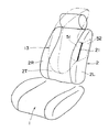
【図2】図1に示すシートの前方斜視図。
【図3】図1に示すシートから展開されたエアバッグの展開形状を示す断面図。
【図4】図1のX4−X4線相当断面図。
【図5】図1に示されるシートバックを前方から見たときの図。
【図6】脆弱部付近における表皮材と低伸長部材とを示す断面図。
【図7】低伸長部材と補強部材との結合例を示す図。
【図8】本発明の別の実施形態を示すもので、図4に対応した断面図。
【符号の説明】
1:シートクッション
2:シートバック
2L、2R:側端部
2T:左右中央部分
13:エアバッグ
21:脆弱部
21a:スリット
31:クッション部材
32:表皮材
32a、32b:折返し部
42:織り目線構成用補強部材(第1補強部材)
43:後方補強部材(第2補強部材)
51:低伸長部材
52:低伸長部材
U:エアバッグユニット
F:乗員
L:織り目線
K1、K2、K3:結合部分[0001]
BACKGROUND OF THE INVENTION
The present invention relates to an automobile side airbag device.
[0002]
[Prior art]
In a side airbag device of an automobile in which an airbag is deployed to the side of a seat, an airbag unit that stores a folded airbag may be disposed in a seat side end portion. In this case, a fragile portion is formed in the skin material of the seat so that the fragile portion is broken by the deployment pressure of the inflated airbag so that the airbag is deployed outside the seat through the fragile portion. ing.
[0003]
By the way, the skin material of the seat is formed of a material that can be considerably expanded so that it can be easily deformed by receiving a load from an occupant. For this reason, when the fragile portion formed in the skin material is broken by the airbag to be deployed, the skin material is considerably stretched and deformed, and the factor that inhibits the fragile portion from being immediately broken, that is, the airbag It becomes a factor that hinders rapid development.
[0004]
In order to prevent large stretch deformation of the skin material when the airbag is deployed, Japanese Patent Application Laid-Open No. 9-39711 discloses that the end portions of a pair of skin materials are stitched together to form a fragile portion. One has been proposed in which one end of a reinforcing band that is difficult to extend is sewn together at a stitched portion between the ends of the material, and the other end of the reinforcing band is joined to a reinforcing member in the seat. That is, there has been proposed a device that suppresses the end portions of the pair of skin members constituting the weak portion by the reinforcing band from being stretched or deformed by a predetermined amount or more when the airbag deployment pressure acts on the weak portion.
[0005]
[Problems to be solved by the invention]
However, in the above-mentioned publication, it is desirable that the ends of the pair of skin materials are easily broken by receiving the deployment pressure of the airbag, that is, the seams are easily broken. On the other hand, it is desirable that the reinforcing band co-sewn to each end of the skin material is not easily uncoupled from each end of the skin material. It will be difficult to satisfy.
[0006]
In view of the above, the applicant applies a pair of low-elongation members made of a material that hardly stretches between the skin material and the cushion member disposed on the back side thereof, with a weak portion formed in the skin material as a boundary. , And developed the low elongation member with the weakened portion side end joined to the skin material. In other words, only the portion of the skin material that is about to be stretched greatly by the deployed airbag is configured to be substantially low stretched by the low stretch member, and the breakability of the weakened portion itself is reduced by the low stretch member. A large elongation deformation of the skin material is prevented by the low elongation member which is not hindered and hardly stretched.
[0007]
As described above, when a low-elongation member is used, it is desired to more effectively prevent a large stretch deformation of the skin material in order to ensure a quicker deployment of the airbag. On the other hand, when the fragile part of the skin material is configured using a slit, it is required to connect the slit side end of the low-extension member to the skin material (slit peripheral part thereof). Since it becomes a part which is easy to be visually observed, the joint part between the skin material and the low elongation member deteriorates the appearance, and some countermeasures are desired in this respect.
[0008]
The present invention has been made in consideration of the above circumstances, and a first object of the present invention is to provide a low-extension member that is difficult to extend on the back side of the skin material on which the fragile portion is formed. An object of the present invention is to provide a side airbag device for an automobile that can more effectively prevent the deformation of the skin material when the bag is deployed.
[0009]
The second object of the present invention is to bond the skin material and the low elongation member in the vicinity of the slit when a low elongation member that is difficult to stretch is disposed on the back surface side of the skin material on which the slit as the fragile portion is formed. An object of the present invention is to provide a side airbag device for an automobile in which the portion does not become a problem in appearance.
[0010]
[Means for Solving the Problems]
In order to achieve the first object, the present invention adopts the following solution. That is, as described in
With weak portion in the skin material is formed at the side edge of the sheet, the airbag unit is disposed on the side end portion corresponding to the fragile portion, the air bag is deployed from the airbag unit wherein In a side airbag device of an automobile that breaks the fragile portion and is deployed outside the seat,
The fragile portion is formed by sewing together a pair of slit side peripheral portions that exist on the boundary of the slit formed in the skin material ,
Each of the pair of slit side peripheral portions has a folded portion folded on the back surface side of the skin material,
On the back surface side of the skin material, a pair of low-extension members that are lower than the skin material are disposed with the slit as a boundary ,
The pair of lower extension member is a rear surface of the respective end portions each folded portion, together with the respectively coupled at the rear surface side of said surface skin material than stitched portion between the pair of slits circumferential edge portion, each The other end is coupled to a reinforcing member in the seat,
It is like that. Preferred embodiments based on the above solution are as described in
[0011]
In order to achieve the second object, the present invention adopts the following solution. That is, as described in
A fragile portion is formed in the skin material at the side end portion of the seat, an airbag unit is disposed in the side end portion corresponding to the fragile portion, and the airbag deployed from the airbag unit is the fragile portion. In a side airbag device for an automobile, the portion is broken and deployed to the outside of the seat, the fragile portion is configured to include a slit formed in the skin material, and the slit of the skin material is the slit A pair of slit side ends with a boundary as a boundary, each having a folded back portion on the back side, between the skin material and the cushion member disposed on the back side, with the slit as a boundary, A pair of low elongation members having a lower elongation than the skin material is disposed, and the slit side end portions of the pair of low elongation members are coupled only to the folded portion of the skin material. For skin material positioned on the surface side of the 該折 return part is adapted not coupled, the coupling between the skin material and the low elongation member, only have been made in the folded portion, it is so. Preferred embodiments based on the above solution are as set forth in
[0012]
【The invention's effect】
According to
[0013]
In addition, providing a pair of low-extension members with the fragile portion (slit) as a boundary is preferable for effectively preventing large elongation deformation at both side portions with the fragile portion of the skin material as the boundary. In addition, the weakened portion pressed by the airbag to be deployed receives a force to be opened by the pair of low-extension members, and is more preferable for obtaining a quick breakage of the weakened portion.
Furthermore, since the fragile portion is formed by stitching together a pair of slit side peripheral portions that exist with the slit formed in the skin material as a boundary, it results from the seating, separation, etc. of the occupant's seat Thus, it is possible to prevent the slit from being unnecessarily opened and closed when the sheet surface is deformed.
Furthermore, in the slit portion for constituting the fragile portion, since the joint portion between the skin material and the low elongation member is set at a position where it cannot be visually observed from the outside, a very favorable appearance can be obtained.
In addition, in a normal time when the airbag is not deployed, a low elongation member disposed on the back surface side of the skin material is preferable in order to prevent the skin material from being deformed as much as possible.
According to the second aspect, the reinforcing member in the seat can be appropriately and effectively used according to the positions of the pair of low-extension members.
[0014]
According to the third aspect, the cushion member is easily broken from a desired position by the deployment pressure of the airbag, which is preferable when the airbag is quickly deployed.
[0015]
According to the fourth aspect, the width of the low extension member is set according to the length of the fragile portion, which is preferable in order to make the low extension member the minimum necessary size. Moreover, since the low-extension member is formed in a sheet shape as a whole, the low-extension member can be satisfactorily aligned with the skin material, which is preferable for preventing the low-extension member from hindering the feel of the skin material. Of course, since it is in the form of a sheet, it can be easily disposed between the skin material and the cushion material, and the surface shape of the sheet is not adversely affected.
[0016]
According to the fifth aspect, the passenger's chest and head can be protected by the airbag.
According to claim 6, the effect corresponding to claim 5 can be obtained with one airbag.
According to the seventh aspect, it is possible to prevent a passenger from colliding with the side wall of the vehicle body.
[0017]
According to the eighth aspect, a specific arrangement position of the airbag unit is provided.
According to the ninth aspect, when the airbag unit is disposed in the seat back, it is preferable in that the airbag is largely deployed in the vertical direction on the side of the occupant to effectively protect the upper body of the occupant. It will be a thing.
[0018]
According to the tenth aspect, a specific arrangement position of the airbag unit is provided.
According to the eleventh aspect of the invention, when the airbag unit is disposed in the seat cushion, the airbag is greatly deployed in the front-rear direction on the side of the occupant, which is preferable for effectively protecting the upper body of the occupant. It will be a thing.
[0019]
According to the twelfth aspect, in the slit portion for constituting the fragile portion, since the joint portion between the skin material and the low elongation member is set at a position where it cannot be visually observed from the outside, a very favorable appearance can be obtained. Further, in a normal time when the airbag is not deployed, the low elongation member disposed on the back surface side of the skin material is preferable in order to prevent the skin material from being deformed as much as possible.
According to the thirteenth aspect, since the low extension member is connected to the reinforcing member in the seat, the effect corresponding to the first aspect can be obtained.
According to claim 14, the effect corresponding to claim 4 can be obtained.
[0020]
DETAILED DESCRIPTION OF THE INVENTION
The overall outline will be described with reference to FIGS. 1, 2, and 4. 1 is a seat cushion, and 2 is a seat back. An airbag unit U is disposed in one
[0021]
A fragile portion (weakening portion) 21 that is elongated in the vertical direction is formed on the front surface of the
[0022]
The
[0023]
Next, with reference to FIGS. 4 and 5, the
[0024]
The aforementioned
[0025]
Between the
[0026]
As is well known, the
[0027]
Further, as a reinforcing member, a texture-constituting reinforcing member (first reinforcing member) 42 for firmly forming a texture line L that becomes a boundary line between the
[0028]
As a reinforcing member, a rear reinforcing member (second reinforcing member) 43a extending in the vertical direction is disposed behind the
[0029]
Between the
One
[0031]
The other
[0032]
The width of each of the
[0033]
Details of the connection between the
[0034]
FIG. 7 shows an example of coupling between the
[0035]
In the embodiment as described above, when the
[0036]
FIG. 8 shows another embodiment, and the same components as those in the above-described embodiment are denoted by the same reference numerals, and redundant description thereof is omitted. In the present embodiment, the
[0037]
The width (axial width) of the slit 55 is substantially the same as the width of the
[0038]
Although the embodiment has been described above, the present invention is not limited to this, and includes the following cases, for example. You may make it provide the
[0039]
The low elongation member can be formed, for example, in a string shape (wire shape) without being formed in a sheet shape. Moreover, a low elongate member can make a part from this sheet-like part to a reinforcement member into a string form as a sheet form which has the width | variety of the same length as the said weak part only about the weak part vicinity. In both of the above examples, the number of the string-like low-extension members is not limited to one, and for example, the string-like low-extension members can be configured by a plurality of parallel ones at predetermined intervals in the longitudinal direction of the weakened portion.
[0040]
The object of the present invention is not limited to what is explicitly stated, but also implicitly includes providing what is substantially preferred or expressed as an advantage.
[Brief description of the drawings]
FIG. 1 is an overall side view of a sheet to which the present invention is applied.
FIG. 2 is a front perspective view of the seat shown in FIG.
3 is a cross-sectional view showing a deployed shape of the airbag deployed from the seat shown in FIG. 1. FIG.
4 is a cross-sectional view corresponding to the line X4-X4 in FIG. 1;
FIG. 5 is a view when the seat back shown in FIG. 1 is viewed from the front.
FIG. 6 is a cross-sectional view showing a skin material and a low elongation member in the vicinity of a fragile portion.
FIG. 7 is a view showing a coupling example of a low extension member and a reinforcing member.
FIG. 8 is a cross-sectional view corresponding to FIG. 4, showing another embodiment of the present invention.
[Explanation of symbols]
1: Seat cushion 2: Seat back 2L, 2R: Side end 2T: Left and right center portion 13: Air bag 21: Fragile portion 21a: Slit 31: Cushion member 32:
43: Rear reinforcing member (second reinforcing member)
51: Low extension member 52: Low extension member U: Airbag unit F: Crew L: Weave lines K1, K2, K3: Joining part
Claims (14)
前記脆弱部が、前記表皮材に形成されたスリットを境にして存在する一対のスリット側周縁部同士を互いに縫い合わせることにより形成され、
前記一対のスリット側周縁部が、前記表皮材の裏面側に折返された折返し部をそれぞれ有し、
前記表皮材の裏面側に、前記スリットを境として、該表皮材よりも低伸長とされた一対の低伸長部材が配設され、
前記一対の低伸長部材は、その各一端部が前記各折返し部の裏面で、前記一対のスリット側周縁部同士の縫い合わせ部分よりも該表皮材の裏面側においてそれぞれ結合されていると共に、その各他端部がシート内にある補強部材に結合されている、
ことを特徴とする自動車のサイドエアバッグ装置。With weak portion in the skin material is formed at the side edge of the sheet, the airbag unit is disposed on the side end portion corresponding to the fragile portion, the air bag is deployed from the airbag unit wherein In a side airbag device of an automobile that breaks the fragile portion and is deployed outside the seat,
The fragile portion is formed by sewing together a pair of slit side peripheral portions that exist on the boundary of the slit formed in the skin material,
Each of the pair of slit side peripheral portions has a folded portion folded on the back surface side of the skin material,
On the back surface side of the skin material, a pair of low-extension members that are lower than the skin material are disposed with the slit as a boundary ,
The pair of lower extension member is a rear surface of the respective end portions each folded portion, together with the respectively coupled at the rear surface side of said surface skin material than stitched portion between the pair of slits circumferential edge portion, each The other end is coupled to a reinforcing member in the seat,
A side airbag device for an automobile.
シートの側端部と左右中央部分との境界付近でかつシートの表面近傍に、前記表皮材が結合されて該側端部と左右中央部分との折り目線を構成するための第1補強部材が配設され、
前記第1補強部材よりもシート裏面側において第2補強部材が配設され、
前記左右一対の低伸長部材のうち車幅方向内方側に位置する一方の低伸長部材の他端部が、前記第1補強部材に結合され、
前記左右一対の低伸長部材のうち車幅方向外方側に位置する他方の低伸長部材の他端部が、前記第2補強部材に結合されている、
ことを特徴とする自動車のサイドエアバッグ装置。 In claim 1,
A first reinforcing member for forming a crease line between the side end portion and the left and right central portion by combining the skin material near the boundary between the side end portion and the left and right central portion of the sheet and near the surface of the sheet. Arranged,
A second reinforcing member is disposed on the back side of the sheet from the first reinforcing member;
Of the pair of left and right low extension members, the other end of one low extension member located on the inner side in the vehicle width direction is coupled to the first reinforcing member,
Of the pair of left and right low extension members, the other end of the other low extension member located on the outer side in the vehicle width direction is coupled to the second reinforcement member.
A side airbag device for an automobile.
前記表皮材とエアバッグユニットとの間に、前記クッション部材が位置され、前記クッション部材のうち展開されるエアバッグに対向する部分に、展開されるエアバッグによって該クッション部材が破断され易いようにするための切り込み部が形成されている、
ことを特徴とする自動車のサイドエアバッグ装置。 In claim 1 or claim 2,
The cushion member is positioned between the skin material and the airbag unit so that the cushion member is easily broken by the deployed airbag at a portion of the cushion member that faces the deployed airbag. A notch is formed,
A side airbag device for an automobile.
前記低伸長部材が全体的にシート状として形成され、
前記低伸長部材の幅が、前記脆弱部の長さとぼ同じ大きさとされている、
ことを特徴とする自動車のサイドエアバッグ装置。 In any one of Claims 1-3,
The low elongation member is formed as a sheet as a whole,
The width of the low elongation member is approximately the same size as the length of the fragile portion,
A side airbag device for an automobile.
エアバッグが、シートに着座されている乗員の頭部と胸部との側方に位置するように展開される、
ことを特徴とする自動車のサイドエアバッグ装置。 In any one of Claims 1-4,
The airbag is deployed so as to be positioned laterally between the head and chest of the occupant seated in the seat.
A side airbag device for an automobile.
前記展開されたエアバッグは、前記エアバッグユニットから連なる胸部保護部分と、該胸部保護部分に連なって該胸部保護部分から上方へ伸びる頭部保護部分とを有するように設定されている、
ことを特徴とする自動車のサイドエアバッグ装置。 In any one of Claims 1-5,
The deployed airbag is set to have a chest protection portion that is continuous from the airbag unit, and a head protection portion that is continuous with the chest protection portion and extends upward from the chest protection portion.
A side airbag device for an automobile.
前記脆弱部およびエアバッグユニットが、シートの左右側端部のうち車体側壁に近い側の側端部に位置されている、
ことを特徴とする自動車のサイドエアバッグ装置。 In any one of Claims 1-6,
The fragile portion and the airbag unit are located at the side end portion on the side close to the vehicle body side wall of the left and right side end portions of the seat,
A side airbag device for an automobile.
前記脆弱部およびエアバッグユニットが、シートバックに設けられている、
ことを特徴とする自動車のサイドエアバッグ装置。 In claim 7,
The fragile portion and the airbag unit are provided in a seat back.
A side airbag device for an automobile.
前記脆弱部が、起立位置にあるシートバックの側端部前面位置において、上下方向に細長く伸びるように形成されている、
ことを特徴とする自動車のサイドエアバッグ装置。 In claim 8,
The fragile portion is formed so as to be elongated in the vertical direction at the front surface position of the side end portion of the seat back in the standing position.
A side airbag device for an automobile.
前記脆弱部およびエアバッグユニットが、シートクッションに設けられている、
ことを特徴とする自動車のサイドエアバッグ装置。 In claim 7,
The fragile portion and the airbag unit are provided in a seat cushion,
A side airbag device for an automobile.
前記脆弱部が、シートクッションの側端部上面位置において、前後方向に細長く伸びるように形成されている、
ことを特徴とする自動車のサイドエアバッグ装置。 In claim 10,
The fragile portion is formed so as to be elongated in the front-rear direction at the upper surface position of the side end portion of the seat cushion.
A side airbag device for an automobile.
前記脆弱部が、前記表皮材に形成されたスリットを含むものとして構成され、
前記表皮材のうち前記スリットを境にした一対のスリット側周縁部がそれぞれ、裏面側に折返された折返し部を有し、
前記表皮材とその裏面側に配設されたクッション部材との間において、前記スリットを境として、該表皮材よりも低伸長とされた一対の低伸長部材が配設され、
前記一対の低伸長部材の前記スリット側端部が、前記表皮材のうち前記折返し部に対してのみ結合されて、該折返し部の表面側に位置する表皮材に対しては結合されていないようにされ、
前記表皮材と低伸長部材との結合が、前記折返し部においてのみ行われている、
ことを特徴とする自動車のサイドエアバッグ装置。A fragile portion is formed in the skin material at the side end portion of the seat, an airbag unit is disposed in the side end portion corresponding to the fragile portion, and the airbag deployed from the airbag unit is the fragile portion. In the side airbag device of the automobile that is to be deployed outside the seat by breaking the part,
The fragile portion is configured to include a slit formed in the skin material,
A pair of slit side peripheral portions with the slit as a boundary among the skin materials each have a folded portion folded back on the back side,
Between the skin material and the cushion member disposed on the back side thereof, a pair of low-extension members that are lower than the skin material are disposed with the slit as a boundary,
The slit side end portions of the pair of low extension members are coupled only to the folded portion of the skin material, and are not coupled to the skin material located on the surface side of the folded portion. And
Bonding of the skin material and the low elongation member is performed only in the folded portion,
A side airbag device for an automobile.
前記一対の低伸長部材のうち前記スリット側端部とは反対側の端部が、シート内に配設された補強部材に結合されている、
ことを特徴とする自動車のサイドエアバッグ装置。 In claim 12,
Of the pair of low-extension members, an end opposite to the slit side end is coupled to a reinforcing member disposed in the sheet.
A side airbag device for an automobile.
前記低伸長部材が、シート状として形成されている、
ことを特徴とする自動車のサイドエアバッグ装置。 In any one of Claims 1-13,
The low elongation member is formed as a sheet,
A side airbag device for an automobile.
Priority Applications (1)
| Application Number | Priority Date | Filing Date | Title |
|---|---|---|---|
| JP15756798A JP3702653B2 (en) | 1998-06-05 | 1998-06-05 | Car side airbag device |
Applications Claiming Priority (1)
| Application Number | Priority Date | Filing Date | Title |
|---|---|---|---|
| JP15756798A JP3702653B2 (en) | 1998-06-05 | 1998-06-05 | Car side airbag device |
Publications (2)
| Publication Number | Publication Date |
|---|---|
| JPH11348709A JPH11348709A (en) | 1999-12-21 |
| JP3702653B2 true JP3702653B2 (en) | 2005-10-05 |
Family
ID=15652517
Family Applications (1)
| Application Number | Title | Priority Date | Filing Date |
|---|---|---|---|
| JP15756798A Expired - Fee Related JP3702653B2 (en) | 1998-06-05 | 1998-06-05 | Car side airbag device |
Country Status (1)
| Country | Link |
|---|---|
| JP (1) | JP3702653B2 (en) |
Families Citing this family (2)
| Publication number | Priority date | Publication date | Assignee | Title |
|---|---|---|---|---|
| JP5309956B2 (en) * | 2008-12-18 | 2013-10-09 | マツダ株式会社 | Side airbag structure for seat |
| JP5433250B2 (en) * | 2009-02-13 | 2014-03-05 | 芦森工業株式会社 | Airbag device |
Family Cites Families (14)
| Publication number | Priority date | Publication date | Assignee | Title |
|---|---|---|---|---|
| JP3762459B2 (en) * | 1995-08-02 | 2006-04-05 | 豊田合成株式会社 | Side airbag device |
| JP3300581B2 (en) * | 1995-11-07 | 2002-07-08 | ジョンソン コントロールズ オートモーティブ システムズ株式会社 | Airbag device for vehicle seat |
| JP3508343B2 (en) * | 1995-11-17 | 2004-03-22 | トヨタ自動車株式会社 | Chest head integrated airbag device |
| JP3815833B2 (en) * | 1996-01-17 | 2006-08-30 | 豊田合成株式会社 | Side airbag device |
| JPH09309399A (en) * | 1996-05-22 | 1997-12-02 | Ikeda Bussan Co Ltd | Air bag device for side collision of vehicle |
| JP3155205B2 (en) * | 1996-07-25 | 2001-04-09 | サンショウ株式会社 | Automotive seat covers |
| JPH1053090A (en) * | 1996-08-09 | 1998-02-24 | Ikeda Bussan Co Ltd | Air bag device of vehicular seat |
| JP3335849B2 (en) * | 1996-09-03 | 2002-10-21 | トヨタ自動車株式会社 | Seat structure with side airbag device |
| JPH10100828A (en) * | 1996-09-27 | 1998-04-21 | Mazda Motor Corp | Side air bag device for vehicle |
| JP3722563B2 (en) * | 1996-09-30 | 2005-11-30 | デルタ工業株式会社 | Energy absorption structure on the side of the vehicle |
| JP3803938B2 (en) * | 1996-10-31 | 2006-08-02 | テイ・エス テック株式会社 | Airbag module built-in seat |
| JPH1035398A (en) * | 1997-03-28 | 1998-02-10 | Mazda Motor Corp | Device for absorbing collitional energy given to side part of car body |
| JP3890695B2 (en) * | 1997-09-19 | 2007-03-07 | トヨタ紡織株式会社 | Ball for seat cover of seat with airbag device |
| JP3831810B2 (en) * | 1997-10-31 | 2006-10-11 | テイ・エス テック株式会社 | Vehicle seat with side airbag device |
-
1998
- 1998-06-05 JP JP15756798A patent/JP3702653B2/en not_active Expired - Fee Related
Also Published As
| Publication number | Publication date |
|---|---|
| JPH11348709A (en) | 1999-12-21 |
Similar Documents
| Publication | Publication Date | Title |
|---|---|---|
| US5938232A (en) | Force directing air bag deployment pocket | |
| US7549672B2 (en) | Side airbag device | |
| CN1760065B (en) | Chair having side safety air bag | |
| JP4400495B2 (en) | Side airbag device | |
| JP5295820B2 (en) | Air bag and air bag device | |
| JP4000740B2 (en) | Airbag deployment device for vehicle seat | |
| JP4877280B2 (en) | Knee protection airbag | |
| CN112498202B (en) | Vehicle seats | |
| JPH10502595A (en) | Soft pack airbag module for side impact | |
| WO2007049538A1 (en) | Occupant restraint device | |
| US8936271B2 (en) | Airbag module for a vehicle seat assembly | |
| WO2011033842A1 (en) | Air belt and air belt device | |
| JP2018127014A (en) | Air bag device | |
| JP6438535B1 (en) | Vehicle seat and sewing method | |
| US11186249B2 (en) | Passenger airbag | |
| JP5527890B2 (en) | Airbag | |
| JP7223621B2 (en) | Airbag | |
| KR20240154018A (en) | Restraint devices, restraint assemblies and seat units | |
| JP4103628B2 (en) | Side airbag device | |
| JP3702653B2 (en) | Car side airbag device | |
| JP3738561B2 (en) | Car side airbag device | |
| JP4063168B2 (en) | Knee protection airbag | |
| CN114867636A (en) | Vehicle seat | |
| JP6620836B2 (en) | Seat with air bag module | |
| EP1820702B1 (en) | Deployment force concentrating system for a car seat mounted airbag |
Legal Events
| Date | Code | Title | Description |
|---|---|---|---|
| A977 | Report on retrieval |
Free format text: JAPANESE INTERMEDIATE CODE: A971007 Effective date: 20040906 |
|
| A131 | Notification of reasons for refusal |
Free format text: JAPANESE INTERMEDIATE CODE: A131 Effective date: 20050104 |
|
| A521 | Written amendment |
Free format text: JAPANESE INTERMEDIATE CODE: A523 Effective date: 20050307 |
|
| TRDD | Decision of grant or rejection written | ||
| A01 | Written decision to grant a patent or to grant a registration (utility model) |
Free format text: JAPANESE INTERMEDIATE CODE: A01 Effective date: 20050628 |
|
| A61 | First payment of annual fees (during grant procedure) |
Free format text: JAPANESE INTERMEDIATE CODE: A61 Effective date: 20050711 |
|
| R150 | Certificate of patent or registration of utility model |
Free format text: JAPANESE INTERMEDIATE CODE: R150 |
|
| FPAY | Renewal fee payment (event date is renewal date of database) |
Free format text: PAYMENT UNTIL: 20090729 Year of fee payment: 4 |
|
| FPAY | Renewal fee payment (event date is renewal date of database) |
Free format text: PAYMENT UNTIL: 20090729 Year of fee payment: 4 |
|
| FPAY | Renewal fee payment (event date is renewal date of database) |
Free format text: PAYMENT UNTIL: 20100729 Year of fee payment: 5 |
|
| FPAY | Renewal fee payment (event date is renewal date of database) |
Free format text: PAYMENT UNTIL: 20110729 Year of fee payment: 6 |
|
| FPAY | Renewal fee payment (event date is renewal date of database) |
Free format text: PAYMENT UNTIL: 20120729 Year of fee payment: 7 |
|
| LAPS | Cancellation because of no payment of annual fees |