JP3614453B2 - Reference line creation device for roof allocation - Google Patents
Reference line creation device for roof allocation Download PDFInfo
- Publication number
- JP3614453B2 JP3614453B2 JP27092293A JP27092293A JP3614453B2 JP 3614453 B2 JP3614453 B2 JP 3614453B2 JP 27092293 A JP27092293 A JP 27092293A JP 27092293 A JP27092293 A JP 27092293A JP 3614453 B2 JP3614453 B2 JP 3614453B2
- Authority
- JP
- Japan
- Prior art keywords
- roof
- line
- reference line
- panel
- plan
- Prior art date
- Legal status (The legal status is an assumption and is not a legal conclusion. Google has not performed a legal analysis and makes no representation as to the accuracy of the status listed.)
- Expired - Fee Related
Links
Images


Description
【0001】
【産業上の利用分野】
本発明は、屋根を設計する際に、該屋根の屋根面に屋根パネルや小屋梁(屋根内部の梁)を割り付けるための基準線を作成する屋根割付用基準線作成装置に関する。
【0002】
【従来の技術】
プレハブ住宅を施工する方法の一つとして、住宅の床、壁、天井、屋根等をパネルを用いて施工する方法が知られている。この施工方法においては、予め、工場等において、芯材を枠組みすることにより枠体を形成し、該枠体の少なくとも一面に面材を貼設することにより床パネル、壁パネル、天井パネル、屋根パネル等を製造し、建築現場において、これらのパネルを組み付けていくことにより建物を構築するものである。
【0003】
ところで、近年、各種の設計においては、コンピュータシステムからなるCAD(computer aided design)システムが用いられており、上記住宅においても、CADシステムを用いて設計が行なわれる場合がある。一般的なCADシステムにおいては、予め、設計要素となる部材の形状データやグラフィックデータやその他のデータをデータベースとして記憶しておき、設計の際にこれらのデータを呼び出し、ディスプレイの製図上に各部材を配置することにより製図が作成され、設計作業を省力化できるようになっている。
【0004】
したがって、従来の住宅のCADシステムのディスプレイ上においては、間取りを決めることにより、壁や床や天井等のデータが読み出されて配置され、屋根の形状(寄せ棟、切妻等)を決めることにより、屋根のデータが読み出されて配置され、窓やドア等の部材と、その位置を決めることにより、窓やドア等のデータが読み出されて配置され、住宅の形状がディスプレイに図形(三面図や斜視図)として示されるとともに、設計図として出力されるようになっている。
【0005】
【発明が解決しようとする課題】
ところで、上記パネルを用いたプレハブ住宅の設計においては、床、壁、天井、屋根に、予めサイズや形状が決められた上記パネルを割り付ける必要がある。また、CADシステム上において、床、壁、天井、屋根は、必ずしも、パネルの形状にしたがって設計されるものではなく、発注先の設計要求にしたがって決められるので、CADシステムの設計図上において、単にパネルを端から順番かつ機械的に割り付けた場合に、隙間ができたり、大きなパネルを配置すればよいところに複数の小さなパネルが配置されたりして、効率の悪いパネルの割り付けとなる可能性が高かった。
【0006】
上述のように効率の悪いパネルの割り付けのまま、住宅を建築するものとした場合には、工場において、上記隙間を埋めるための特注サイズのパネルを製造したり、大きいパネルに比較して生産効率の悪い小さなパネルを多く製造したりする必要があり、工場におけるパネルの生産性を低下させていた。さらに、建築現場においては、小さなパネルや隙間を埋めるパネルを用いることによりパネルの接合作業が増えたり、パネル同士の僅かな隙間を埋めるための部材を製造したりしなければならなかった。
【0007】
したがって、パネルの割り付け方法が悪いと、住宅の生産性を低下させるとともに、そのコストを増大させることになる。
特に、図18に示すような屋根1は、複数の傾斜した屋根面2…から立体的に構成されるので、壁や床のように平面上でパネルの割り付けを行なうことが困難であり、屋根1の傾斜した屋根面2…を別々に扱うとともに、屋根勾配の側断面図等を用いてパネルの割り付けを決める必要があった。
【0008】
また、図18に示す屋根(段棟屋根)1においては、二つの切妻屋根1a、1bが複合した形状を有しており、一方の切妻屋根1aの一つの屋根面2(a)の妻側から、上記一方の切妻屋根1aの棟(主棟)3aに平行、かつ、該主棟3aより低く延出した棟(下棟)3bを有する他方の切妻屋根1bが延出した形状とされている。そして、上記屋根1には、一方の屋根1aと他方の屋根1bとの接合部において、屋根面2、2が上下に重複した部分ができるとともに、一方の切妻屋根1aの妻側端部(ケラバ)4が途中から他方の切妻屋根1bと連続した形状となっている。
【0009】
そして、一般に屋根パネルにおいては、外観や構造状の問題から屋根の下面が外部にでるケラバ用の屋根パネルと同じく屋根の下面が外部にでる軒用の屋根パネルと、ケラバでかつ軒に配置される軒用ケラバ屋根パネルと、下面が天井裏に隠れてしまう通常の屋根パネルとを区別しているために、上記のように屋根1aのケラバ4部分とケラバ4部分でないところが連続して配置された場合に、ケラバ用と通常用との屋根パネルの割り付けが煩雑なものとなっていた。
以上のことから、図18に示されるような屋根1の設計においては、CAD上で、屋根パネルを効率良く自動的に割り付けることが極めて困難であった。
【0010】
本発明は、上記事情に鑑みてなされたものであり、上記パネルから構築される建物が、上記段棟屋根を有する場合に、上記段棟屋根の屋根面に効率良くケラバ、及び軒及び通常の屋根パネルと、小屋梁とを配置するために、これら屋根パネルの配置及び小屋梁の配置の基準となる基準線を屋根面上に作成する屋根割付用基準線作成装置を提供することを目的とするものである。
【0011】
【課題を解決するための手段】
本発明の請求項1に記載された屋根割付用基準線作成装置は、複数の屋根パネルを敷き詰めることにより形成され、かつ、複数の傾斜した屋根面から形成される屋根を設計するに際し、設計すべき屋根の屋根面上に上記屋根パネルの位置や上記屋根パネルを支持する梁の位置を決める基準線を作成する屋根割付用基準線作成装置であって、予め入力された平面図上の屋根の形状を記憶する形状記憶手段aと、上記形状記憶手段aに記憶された平面図上の屋根の屋根面に、該屋根面の傾斜方向に沿って屋根パネルの強度に対応した間隔をあけるとともに上記傾斜方向に対して直角に配置され、かつ、少なくとも上記傾斜方向に直角な梁の位置を示す第1の基準線を作成する第1の基準線作成手段bと、少なくとも主棟を棟とする第1の屋根と該第1の屋根の上記主棟を上側縁とする一つの屋根面の妻側側縁から該主棟に平行にかつ主棟より低く延出する下棟を棟とする第2の屋根とからなる段棟屋根において、上記屋根面の妻側の側縁と上記下棟の交点を基準点として認識する基準点認識手段cと、上記第1の屋根の上記下棟が延出した屋根面において、該屋根面の傾斜方向と直角に配置されるとともに上記基準点を含み、かつ、上記屋根パネルの上下の接合部及び該接合部に配置される梁の位置を示す第2の基準線を作成する第2の基準線作成手段dとを具備してなることを上記課題の解決手段とした。
【0012】
そして、本発明の請求項2に記載された屋根割付用基準線作成装置は、上記形状記憶手段aに記憶された平面図上の屋根において、上記第2の基準線と、上記第1の屋根の第2の屋根との接合部側の妻壁の位置を示す妻壁線との交点を補助点として認識する補助点認識手段eと、上記第2の基準線を上記基準点から上記補助点を越える位置までに限定する第2の基準線限定手段fとを備えたことを上記課題の解決手段とした。
【0013】
また、本発明の請求項3に記載された屋根割付用基準線作成装置において、上記形状記憶手段aに記憶された平面図上の屋根は、該屋根の形状を示す各値が基準長さ単位の整数倍にされるとともに、各手段により平面図上に作成される線の位置を示す値は、上記基準長さ単位の整数倍とされていることを上記課題の解決手段とした。
【0014】
【作用】
上記請求項1記載の構成によれば、上記形状記憶手段aは、平面図上の屋根の形状を記憶しており、屋根パネルの位置や屋根パネルを支持する梁の位置を決める基準線は、上記平面図上で作成されることになる。
そして、第1の基準線作成手段bは、上記平面図上の屋根面に、該屋根面の傾斜方向に所定の間隔を開けて少なくとも上記梁の位置を示す第1の基準線を作成する。
【0015】
また、基準点認識手段cは、少なくとも主棟を棟とする第1の屋根と該第1の屋根の上記主棟を上側縁とする一つの屋根面の妻側側縁から該主棟に平行にかつ主棟より低く延出する下棟を棟とする第2の屋根とからなる段棟屋根において、上記屋根面の妻側の外周線と上記下棟の交点を基準点とする。
そして、上記第2の基準線作成手段dが上記第1の屋根の第2の屋根と接合する部分において、上記第1の屋根の上記下棟が延出した屋根面において、該屋根面の傾斜方向と直角に配置されるとともに上記基準点を含む位置、すなわち、屋根のケラバとなる部分とケラバとならない部分の境界の位置に第2の基準線を作成して、ケラバ用の屋根パネルを配置する部分と通常の屋根パネルを配置する部分の境界線を明示する。すなわち、ケラバ用屋根パネルと通常の屋根パネルを屋根の形状に対応して割り付けることができる。
【0016】
上記請求項2記載の構成によれば、上記補助点認識手段eにより妻壁を示す妻壁線と基準点の交点が補助点とされる。すなわち、第2の基準線の妻壁の位置に補助点が配置される。
次いで、上記第2の基準線限定手段fが、上記第2の基準線を基準点から補助点を越える位置までに第2の基準線を限定する。すなわち、第2の基準線の長さを、上記妻壁上に配置されるケラバ用パネルの幅の長さに対応させることが可能となる。
【0017】
上記請求項3記載の構成によれば、平面図上において、屋根の形状を示す各値及び上記各手段により作成される線の位置を示す値は、上記基準長さ単位の整数倍とされているので、屋根パネルや梁を容易に規格化することができる。
なお、上記「課題を解決するための手段」及び「作用」の欄において、図1を参照して説明をしたが、本発明が図1の構成に限定されるものではない。
【0018】
【実施例】
以下に、本発明の一実施例の屋根割付用基準線作成装置を図面を参照して説明する。
なお、この実施例の基準線作成装置は、本発明の屋根割付用基準線作成装置を、コンピュータシステムにより構成されるCADシステムに応用したものであり、この実施例において、基準線作成装置は、CADシステムの一部として機能するようになっている。そして、CADシステムの一部である基準線作成装置は、上記CADシステムにより設計された屋根に、屋根パネルや小屋梁を割り付けるための基準線を作成するものである。また、上記CADシステムは、上記設計された屋根に上記基準線に基づいて屋根パネルや小屋梁を割り付けるものである。
【0019】
ここで、上記基準線作成装置を説明する前に、説明を容易にするために、図2を参照して屋根の基本的な構造を説明する。
図2は、屋根パネルP…により構成される寄棟屋根の一例を示したものである。図2に示すように、屋根5の下方は、複数の壁(外壁6a、内壁6b)6…により建物が構成されている。そして、これら壁6…のうちの耐力壁もしくは支持壁となるものについては、その上側縁が屋根5の裏面まで達するように立ち上げられている。例えば、屋根5の屋根面2の傾斜方向と平行に配置される内壁6b、6bは、その上端部が屋根5裏面に沿うように三角形状に形成され、屋根面2…の傾斜方向と直角に配置される外壁6a…は、その上端面が水平にされている。
なお、上記耐力壁は、垂直荷重と水平荷重との両方を受けるものであり、上記支持壁は、主に垂直荷重を受けるものである。
【0020】
そして、これら壁6…の上端部には、屋根5を支持する小屋梁(屋根梁7、B梁8、小梁9)Hが掛け渡されている。これら小屋梁Hのうち、両端を壁6、6に掛ける梁を大梁と称し、この大梁には、屋根梁7とB梁8の二種類がある。
上記B梁8は、途中で折れ曲がるか、登り形状(斜めに傾斜した直線状)の梁であり、少なくとも一部が屋根面2の傾斜方向に平行に配置されるものである。
上記屋根梁7は、両端を壁6、6に水平に架け渡す梁であり、屋根面2…の傾斜方向に対して直角に配置されるものである。
そして、少なくとも一端が上記B梁8、屋根梁7に掛けられた梁を小梁9と称する。
【0021】
また、上記大梁(屋根梁7、B梁8)と小梁9との区別は、小屋梁Hの断面積(この実施例において上記各小屋梁Hは、左右の厚みが略同じに形成され、上下の厚みを代えることにより耐力を調整している。)ではなく、小屋梁Hの両端部を支持するものにより決められるものとしており、両端部が壁6、6に支持されているものだけが大梁(屋根梁7、B梁8)となり、梁の両端部の少なくとも一方が屋根梁7もしくはB梁8に支持されているものが小梁9となる。
なお、屋根パネルP…により構成される屋根5においては、一般の現場軸組の建物に形成される垂木に代わって屋根パネルP…の芯材(図示略)が屋根面2を支持するようになっている。
【0022】
そして、上述のような小屋梁Hの上に屋根5が設置されている。
そして、各屋根面2には、基本的に、二つの屋根面2が勾配上で接合された隅棟線2aに接する部分に三角形状の屋根パネルP(1)が配置され、それ以外の部分に矩形状の屋根パネルP(2)が配置されている。そして、これらの屋根パネルP…同士を接合するとともに、屋根パネルP…と上記小屋梁Hとを接合することにより、屋根1が形成されている。
【0023】
この際に、上記傾斜に沿って上下に接合される屋根パネルP…の接合部S及び棟2bには、必ずその裏面に屋根パネルP…の上下側縁を支持する小屋梁Hが配置されるようになっている。図2においては、屋根パネルP…の接合部Sに沿って、屋根梁7、B梁8の水平部分、小梁9が配置されている。
なお、屋根1の形状が複雑な場合には、上記三角形状や矩形状の屋根パネルP…以外に、台形状や菱形状の屋根パネル(図示略)が用いられる。また、基本的に屋根面2が矩形状となる切妻屋根の屋根パネルPにおいては、矩形状の屋根パネルP(2)が配置される。さらに、屋根パネルPには、下面が外壁より外側にでる部分、例えば、軒の部分及びケラバ(切妻屋根の妻側端部)の部分において、外観や構造状の問題により、下面が屋根裏に隠れる通常の屋根パネルPとは異なる軒用屋根パネルP(n)(図17に図示)及びケラバ用屋根パネルP(k)(図17に図示)及びケラバ軒用屋根パネルP(kn)(図17に図示)が用いられる。
【0024】
次に、図3に示される基準線作成装置の基本構成を参照して、基準線作成装置を説明する。
図3に示す上記基準線作成装置を備えたCADシステムは、周知のように中央演算処理ユニットや内部記憶装置となるRAM及びROM等のメモリなどを備えた演算処理装置(コンピュータ)11と、ハードディスク、光磁気ディスク等からなる補助記憶装置12と、カラーディスプレイ等からなる表示装置13と、キーボード等からなる入力装置14と、マウス、タブレット、デジタイザー等からなるポインティングデバイス(座標位置入力装置)15と、プリンター及びプロッター等からなる出力装置16とを基本的構成とするものである。
【0025】
上記補助記憶装置12には、住宅を構築するための各種部材の内部コードNo.、グラフィックデータ、形状データ、発注用製品コードNo.、各種部材の単価等がデータベースとして記憶されるとともに、CADシステム上で設計されたデータが記憶されている。
また、上記補助記憶装置12は、CADシステムにより設計されたデータとして屋根の形状を示すデータを記憶する。
【0026】
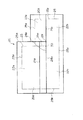
なお、上記補助記憶装置12に記憶された屋根5の形状のうち、基準線作成装置で用いられる屋根の形状データは、図4に示すように平面図上の屋根20である。なお、図4の平面図上の屋根20は、上記解決すべき課題において用いた図に示す屋根1と同様に二つの切妻屋根20a、20bが複合された形状を有する。
そして、一方の屋根20aは、主棟(以後平面図上の屋根20においては主棟線と称する)21aを棟とする二つの屋根面22a、22aからなる。
そして、一方の屋根20aの一つの屋根面22aの主棟線21aより下の妻側側縁から下棟(以後平面図上の屋根20においては下棟線と称する)21bが、上記主棟線21aと平行に延出しており、この下棟線21bを棟として、他方の屋根20bが形成されている。
【0027】
そして、一方の屋根20aの下棟線21bが延出する屋根面22aと、他方の屋根20bの一つの屋根面22bとは、面一に形成され、一方の屋根20aの残りの屋根面22aと他方の屋根20bの残りの屋根面22bとは、一方の屋根20aと他方の屋根20bとの接合部分において、一方の屋根20aの屋根面22aと他方の屋根20bの屋根面22bとが図4の斜線部22cで重複した形状となっている。この実施例においては、このような構成の屋根20を段棟屋根と称する。
【0028】
また、上記補助記憶装置12において、平面図上の屋根20には、上記主棟線21a及び下棟線21bの他に、屋根20の外周を示す外周線23と、これら主棟線21a及び下棟線21b及び外周線23により区画された上記屋根面22a、22bと外壁6aが屋根に接合する部分を示す外壁線25などとから構成されるものである。
なお、平面図上の屋根20には、外壁6a以外の内壁(支持壁もしくは耐力壁)を示す内壁線(図示略)も含まれる。また、上記外壁線25は、屋根面22a、22bの傾斜方向に直角に配置された水平な桁線25a部分と、屋根面22の傾斜方向に沿った妻壁線25b部分とに別れる。また、寄棟屋根やその他の屋根においては、上記主棟線21aや下棟線21bや外周線23以外に、屋根面22a、22bを区画する線として、二つの屋根面が勾配上で棟状に接合された隅棟を示す隅棟線(図示略)や二つの屋根面が谷状に接合された谷隅を示す谷隅線(図示略)等が含まれる場合がある。
【0029】
また、上記補助記憶装置12には、屋根パネルP…の長さの許容値が、屋根20の傾斜角、積雪量の異なる地域、重量の異なる屋根材の種類に対応したデータテーブル(図5に図示)Tとして記憶されている。なお、図5に示すデータテーブルTにおいては、データテーブルT上の実際の値を省略して図示した。
上記データテーブルTに登録された値は、屋根パネルP…の強度に基づいて決められた屋根20の傾斜方向に沿った屋根パネルP…の平面図上の長さ(以下、許容値と称す)と、屋根20の桁線25a上に配置される屋根パネルP…の上側縁と上記桁線25aとの平面図上の長さ(以下、初回許容値と称す)とを示すものである。
【0030】
そして、上記許容値もしくは初回許容値となる屋根パネルP…の平面図上の長さとは、図6に示すように屋根面22a、22bに屋根パネルP…を配置した際の屋根パネルP…の上下側縁間の水平距離L(三角形状の屋根パネルの場合は、例えば、頂点と底辺との水平距離)であり、実際の屋根パネルP…の長さSより短いものである。なお、屋根パネルP…の平面図上の長さは、後述するモジュール単位となっている。
【0031】
上記データテーブルTの値(許容値、初回許容値)は、屋根10の傾斜角(勾配)の後述する種類(屋根の勾配イ、ロ、ハ)と、積雪量により分けられた地域(A地域、B地域、C地域、D地域、E地域)と、瓦、金属、スレート等の屋根葺材の種類(ア、イ、ウ)とにより分けられている。
屋根の傾斜角、積雪量の異なる地域、重量の異なる屋根葺材で分類された許容値は、上述のように屋根パネルP…の強度に基づいて決められたものであり、屋根20の傾斜方向に沿った屋根パネルP…の平面図上の長さが、上記許容値以内の場合には、上記屋根パネルP…を屋根20の傾斜に合わせた角度で配置し、かつ屋根パネルP…の上下側縁を梁によって支持した状態で、屋根葺材、屋根20上の積雪等による荷重に充分に耐え得るようになっている。
【0032】
また、初回許容値については、桁線25a上に配置される屋根パネルP…が、桁線25aの部分で外壁6aの上端に支持される形態となるので、桁線25a上の外壁6aに支持された屋根パネルP…の強度に基づいて決められたものであり、桁線25aから屋根パネルP…上側縁までの長さが上記初回許容値の範囲ならば充分な強度を保持できるようになっている。
なお、上記データテーブルTにおいて、二つに分けられた項の下側は、屋根20の屋根葺材に雪止め(屋根20から雪がすべり落ちることにより、雨樋等を傷つけるの防止するものであり、結果的に屋根20上に溜まる雪の量を増やすことになる)を設けた際の許容値もしくは初回許容値である。
【0033】
上記演算処理装置11は、周知の住宅用のCADシステムとしての機能を有するとともに、この演算処理装置11を用いて設計された屋根面22a、22bに基準線を作成し、該基準線に基づいて、屋根面22a、22bに小屋梁H及び屋根パネルP…を配置する機能を有する。
なお、上記基準線は、少なくとも屋根面22a、22bの傾斜方向に直角に配置された小屋梁(一般に母屋という)Hの位置を示すものなので、この実施例において、以下、母屋線と称する。
【0034】
また、母屋線には、図7及び図8に示すように、屋根パネルP…同士の上下の接合部S(図2に図示)及び該接合部Sを支持する小屋梁Hとの位置を示す相対母屋線(第1の基準線)26と、屋根パネルP…の上下側縁の間を支持する小屋梁Hの位置を示す候補母屋線(第1の基準線)27とがある。また、母屋線には、後述するように屋根20が段棟屋根の場合に設けられ、かつ、屋根パネルP…同士の上下の接合部S(図2に図示)及び該接合部Sを支持する小屋梁Hの位置を示す絶対母屋線(第2の基準線)28(図11に図示)が設定されている。
【0035】
そして、上記演算処理装置11は、上記補助記憶装置12から図4に示すような上記平面図上の屋根20の形状を読み出し、上記屋根20の屋根面22a、22bにおいて、該屋根面22a、22bの傾斜方向に沿って上記補助記憶装置12から読み出した許容値毎もしくは製造される屋根パネルPの長さの最大値毎に、図7に示す相対母屋線26を上記屋根面22a、22bの傾斜方向と略直角な方向に沿って作成する機能を有する。
また、演算処理装置11は、上記相対母屋線26を上記最大値毎に作成した場合に、上記相対母屋線26と重ならない位置に、屋根面14…の傾斜方向に沿って上記補助記憶装置12から読み出した許容値毎に、図8に示すように候補母屋線27を上記屋根面22a、22bの傾斜方向と略直角な方向に沿って作成する機能を有する。
【0036】
また、上記演算処理装置11は 図9に示すように、少なくとも主棟線21aを棟とする一方の屋根20aと該屋根20aの上記主棟線21aを上側縁とする一つの屋根面22a、22bの妻側側縁から該主棟線21aに平行にかつ主棟線21aより低く延出する下棟線21bを棟とする第2の屋根20bとからなる段棟屋根20において、上記屋根面22a、22bの妻側の外周線23と上記下棟線21bの交点を基準点29として認識する機能を有する。
また、図10に示すように、一方の屋根20aの上記下棟線21bが延出した屋根面22a、22bにおいて、該屋根面22a、22bの傾斜方向と直角に配置されるとともに上記基準点29を含み、かつ、上記屋根パネルPの上下の接合部S(図2に図示)及び該接合部Sに配置される小屋梁Hの位置を示す線分28aを作成する機能を有する。
【0037】
さらに、演算処理装置11は、図10に示すように、上記補助記憶装置12に記憶された平面図上の屋根20において、上記線分28aと、一方の屋根20aの他方の屋根20bとの接合部の妻壁線25bとの交点を補助点30として認識する機能を有するとともに、図11に示すように、上記絶対母屋線28を上記基準点39から上記補助点30を越える位置までに限定する機能を有する。
【0038】
ここで、この実施例の屋根割付用基準線作成装置による母屋線の作成方法を説明する前に、上記CADシステム上での屋根の設計に際し、予め決められた規則について説明する。
該規則は、予め形成された上記パネルにより構築される建物の設計を容易とするとともに、設計された建物の強度を、予め設定された基準以上のものとするために設けられたものである。
【0039】
1、平面図上において基準長さ単位を用いる。
まず、この実施例の上記CADシステムにおいては、建物を設計するに際して、平面図上における基準長さ単位(モジュール)で設計されるものとなっている。そして、最低の単位としては、1/4もしくは1/8モジュールのものを用いている。なお、モジュールは、建物を設計する上で、基本的な長さを1単位としたことにより、1モジュールが最低の単位とならずに、1/4もしくは1/8モジュールが最低の単位となっている。
【0040】
したがって、壁、床、天井等の縦横の長さは、基本的に、上記1/4もしくは1/8モジュールの整数倍となるように設計される。したがって、上記壁、床、天井等を上記モジュール単位で設計するとともに、壁、床、天井等を構成する壁パネル、床パネル、天井パネル等を、上記モジュール単位で設計すること、すなわち、各パネルの形状を上記モジュール単位で規格化することにより、パネルから構築される建物の設計を容易なものとすることができるようになっている。
【0041】
なお、パネル同士やパネルと他の部材との接合部の取り合いに勝ち負けがある場合には、パネルのサイズは、上記モジュール単位から上記勝ち負けの分だけずれた形状となる。また、建物の設計は、必ずしも上記モジュール単位で行なう必要はなく、敷地の条件などによりモジュール単位では効率の良い建物設計が行なえない場合は、特注のパネルや、建築現場においてモジュールからずれた部分を製作することにより対応することができる。
【0042】
そして、屋根20を設計する際に、屋根面22a、22b及び屋根パネルP…の縦横のサイズを上記モジュール単位にした場合には、屋根20が天井や床に対して傾斜した屋根面22a、22bからなることにより、屋根20と床及び天井との設計にずれができてしまい、床や天井に対応して屋根20を設計することが困難になってしまうので、平面図上に投影された屋根20をモジュール単位で設計するものとした。
平面図上に投影された屋根20をモジュール単位(モジュール単位)で設計することにより、従来のように各屋根面22a、22bの勾配を有する屋根面22a、22b毎の断面図等により、屋根パネルP…の割り付けを決める必要がなくなり、屋根20の平面図一枚から屋根パネルP…の割付を決定することが可能となる。
【0043】
なお、図6の屋根面22a、22bの断面図に示すように、平面上の屋根パネルP…の上下側縁を示す線は、屋根パネルP…の下面側の上下側縁とする。また、上述のように平面図上の長さをモジュール単位とすることにより、図6に示すように、平面上のモジュール単位の屋根パネルP…の長さと、実際の屋根パネルP…の長さとは、異なることになり、屋根パネルP…は壁パネル等の規格からはずれることになるが、後述するように屋根面22a、22bの傾斜角度を規格化することにより、屋根パネルP…を規格化することができるようになっている。
【0044】
2、屋根の屋根面の傾斜角度を規格化する。
上記屋根20において、屋根勾配は、図6に示すようにa/bで表すとともに、その屋根勾配が5種類とされている。
また、屋根20の形状が切妻として扱われるものについては、上記屋根勾配の全てを用いることができるが、屋根20の形状が寄棟として扱われるものについては、
5種類の勾配のうちの一部を用いることができることになっている。
また、寄棟屋根においては、寄棟屋根の全ての屋根面を同一の勾配のものとする。
【0045】
3、屋根の軒の出を規格化する。
上記屋根において、外壁線25から延出する部分の長さ(軒の出)は、図12に示すように上記1/4モジュール単位(一部1/8モジュール単位も含む)で、5種類の長さ(N1、N2、N3、N4、N5)に設定されている。
【0046】
なお、これらの規則は、設計及び施工を容易とするために、設けたものであり、この実施例の基準線作成装置において、上記規則からずれた屋根面においても基準線を作成することが可能である。しかし、上記規則からずれた場合には、設計する際に強度を再計算をしたり、実際に建物を建築する際に、規格外の屋根パネルを用いたりする必要があり、設計及び施工の生産性を低下させる可能性がある。
【0047】
次いで、図13のフローチャートと、図7及び図8の平面図上の屋根と、図14及び図15の屋根面22a、22bとを参照して、基準線作成装置による相対母屋線26及び候補母屋線27の作成方法を説明する。
なお、ここでは、図14及び図15に示す段棟屋根20の屋根面22a、22bを例にとって説明するが、図7及び図8に示すように、相対母屋線26及び候補母屋線27は、平面図上の屋根20の全面に対して等高線状(切妻屋根においては、平行線状)に作成されるものである。
まず、CADシステムにより屋根5の形状が決められ、図4に示すような屋根20の平面図が補助記憶装置12に記憶されるとともに、屋根勾配、積雪量により決められる地域、屋根葺材、雪止めの有無が入力されて記憶される。
【0048】
上記屋根20の平面図には、屋根の外周を示す外周線23と、上記主棟線21aと、下棟線21bと、上記外壁線25(桁線25a、妻壁線25bを含む)と、内壁のうちの耐力壁もしくは支持壁の位置を示す内壁線(図示略)等が配置されている。
そして、上記外周線23の内部が屋根20領域とされ、上記外周線23、主棟線21a、下棟線21bで囲まれた範囲が、各屋根面22a、22bとされている。
なお、上記各線分は、それぞれCADシステムにおいて設計された段階で意味づけされており、基準線作成装置に上記屋根20の形状が読み出された際に、それぞれ外周線23、主棟線21a、下棟線21b、外壁線25、桁線25a、妻壁線25b等として認識された状態となっている。
【0049】
そして、補助記憶装置12の上記データテーブルTから初回許容値を読み出す。この際には、予め入力された屋根勾配、積雪地域、屋根葺材に対応する初回許容値をデータテーブルTから選択して読み出す(ステップA1)。
次いで、図7及び図8と図14及び図15に示すように、桁線25aから屋根20の傾斜方向に沿って上記初回許容値の距離mに最初の相対母屋線26(a)を作成する(ステップA2)。
次いで、初回許容値と同様に、補助記憶装置12の上記データテーブルTから許容値を読み出す(ステップA3)。
【0050】
そして、該許容値が所定の値以下の場合には(ステップA4)、許容値を最大値とする(ステップA5)。すなわち、許容値が予め決められた所定の値以下の場合には、許容値を越える値(ここでは規格化された屋根パネルの長さの最大値)を許容値とすることで、短い間隔で、相対母屋線26が作成されることにより、短い屋根パネルP…が割り付けられるのを防止している。
【0051】
次いで、上記最初の相対母屋線26から傾斜方向に沿って上記許容値に対応する距離n(図7、図14及び図15に図示、なお図15の距離n’は、上記ステップA5において、3モジュールとされたもの)毎に相対母屋線26(b)を作成する(ステップA6)。
なお、図8に示すように、最初に作成した相対母屋線26から棟までの距離が許容値以下の場合には、そこで、相対母屋線26の作成作業を終了する。また、上記相対母屋線26(b)を作成した際に、該相対母屋線26(b)から棟までの距離が許容値より長ければ、図14に示すように、相対母屋線26(b)から許容値の距離に、さらに相対母屋線26(b)を作成することを繰り返す。
そして、相対母屋線26の作成が終了した段階で、作成された相対母屋線26を補助記憶装置12に登録する(ステップA7)。
【0052】
次に、上記許容値を補助記憶装置12から読み出す(ステップA8)。そして、上記相対母屋線19の作成において、許容値が上記所定の値より大きければ、許容値毎に相対母屋線26が引かれており、使用される屋根パネルP…は、許容値以下の長さのものであり、屋根パネルP…の中央部を支持する小屋梁Hを必要としない。したがって、許容値が所定の値より大きい場合に(ステップA9)、例えば、図7及び図14に示すように、候補母屋線27を作成せずに作業を終了する。
【0053】
次いで、図8及び図15に示すように、読み出された許容値が所定の値以下の場合には、上述のように作成された相対母屋線26から、屋根面22a、22bの傾斜方向から上に向かって上記許容値毎に次の相対母屋線26に至るまで、候補母屋線27(a)を作成し、さらに次に相対母屋線26から上記許容値毎に候補母屋線27(b)を作成する作業を相対母屋線26がなくなるまで行なう(ステップA10)。
そして、平面図上に作成された候補母屋線27は、上記相対母屋線26と同様に補助記憶装置12に登録する(ステップA11)。
以上により、相対母屋線26及び候補母屋線27の作成を終了する。
【0054】
次に、基準線作成装置においては、図11に示す絶対母屋線28の作成を行なう。これら絶対母屋線28の作成について図16のフローチャートを参照して説明する。
まず、上記補助記憶装置12に記憶された平面図上の屋根20(相対母屋線26及び候補母屋線27が作成されたもの)を呼び出し、該平面図上の屋根20において、図9に示すように、下棟線21bと、段棟の屋根20の主棟線21aを棟とする一方の屋根20aの妻側の外周線23との交点を基準点29として認識する(ステップB1)。なお、図9においては、相対母屋線26及び候補母屋線27を省略した。
【0055】
次に、上記ステップB1で基準点29が認識できなかった場合、すなわち、屋根20が段棟屋根でない場合には、絶対母屋線28を作成せずに処理を終了する(ステップB2)。
次に、図10に示すように、上記基準点29を通り、傾斜方向と直交して屋根面22aを遮る線分28aを作成する(ステップB3)。この場合には、主棟線21aを棟とする屋根20aの屋根面22aのうちの下棟線21bを棟とする屋根20bの一つの屋根面22bと面一になる屋根面22a上に上記線分28aが作成されることになる。
すなわち、上記一方の屋根20aの一つの屋根面に、上記他方の屋根20bの下棟線21bの延長線となる線分28aが作成されることになる。
【0056】
この際に、上記線分28aが作成できない場合、例えば、誤って基準点29が認識されて上記線分28aが作成できないような場合には、絶対母屋線28の作成処理を終了する(ステップB4)。
次に上記線分28aと交差する妻壁線25bの延長線(壁際線)25cを認識する(ステップB5)。
なお、壁際線25cは、他方の屋根20b上に外壁として認識されない妻壁の位置を示すものであり、妻壁線25bの一部と考えることができる。
【0057】
そして、もし壁際線25cが認識できない場合(ステップB6)には、上記線分28aを絶対母屋線28とする(ステップB7)。
図10に示すように、壁際線25cが認識できた場合には、上記線分28aと壁際線25cとの交点を補助点30として取得する(ステップB8)。
そして、上記線分を上記補助点30により分割する(ステップB9)。そして、分割された線分28aを補助点からそれぞれ所定モジュール延長し(ステップB10)、基準点29を端点とする線分28aを絶対母屋線28とする(ステップB11)。すなわち、上記線分28aを基準点から補助点を所定モジュール越えた位置までに限定する。
【0058】
そして、CADシステムにおいては、相対母屋線26、候補母屋線27、絶対母屋線28の作成が終了した平面図上において、屋根20の小屋梁Hの配置及び屋根パネルP…の配置を行なう。
この際には、上記相対母屋線26、候補母屋線27及び絶対母屋線28の部分に、必ず屋根面22a、22bを、該屋根面22a、22bの傾斜に対して直角な方向に沿って支持する小屋梁Hが割り付けられる。
また、各屋根パネルP…は、上述のように、相対母屋線26及び絶対母屋線28上で上下に接合されることになるので、屋根パネルP、Pの上側縁及び下側縁が相対母屋線26及び絶対母屋線28上に配置されることになる。
【0059】
そして、各屋根面22a、22bにおいては、基本的に屋根面22a、22bの下側縁(外周線23)と相対母屋線26もしくは絶対母屋線28との間、相対母屋線26と相対母屋線26もしくは絶対母屋線28との間、相対母屋線26もしくは絶対母屋線28と屋根面22a、22bの上側縁(棟)との間に、それぞれ屋根パネルP…が割り付けられることになる。なお、屋根パネルP…の左右の幅は、屋根面22a、22bの左右側縁間の距離に対応して決められる。
【0060】
そして、本実施例の段棟屋根20のように基本的に、切妻屋根の屋根面は、矩形状もしくは矩形を組合せた形状となるので、矩形状の屋根パネルPが配置されることになる。
そして、上述したように屋根パネルPには、軒先部分の下面が露出する軒先用屋根パネルP(n)と、切妻屋根の妻側が露出するケラバ用屋根パネルP(k)と、切妻屋根の妻側でかつ軒先に配置される軒先ケラバ用屋根パネルP(nk)と下面が屋根裏に隠される通常の屋根パネルPとがある。そして、図17に示すように、軒先部分には、軒先用屋根パネルP(n)が配置され、ケラバ部分にはケラバ用屋根パネルP(k)が配置され、屋根面22a、22bの軒先の角部分には、軒先ケラバ屋根パネルP(nk)が配置されることになる。
【0061】
また、上記絶対母屋線28の上部は、第1の屋根20aのケラバとなっているので、ケラバ用屋根パネルP(k)が配置され、絶対母屋線28の下側は、通常の屋根パネルPもしくは軒先用の屋根パネルP(n)が配置されることとなる。すなわち、上記絶対母屋線28は、ケラバ用屋根パネルP(k)を配置しなければならない領域と、通常の屋根パネルPもしくは軒先用屋根パネルP(n)を配置しなければならない領域との境界に作成されていることになる。そして、絶対母屋線28が上記境界に配置されることにより、上記境界には、CADシステムによる設計において必ず小屋梁Hが配置されることになる。そして、上記絶対母屋線28を境として、ケラバ用屋根パネルP(k)と通常の屋根パネルPもしくは軒先用屋根パネルP(n)とをそれぞれ配置しなければならない領域に配置することができる。
【0062】
また、上記絶対母屋線28においては、絶対母屋線28の長さを上記壁際線25cの交点から所定モジュール延長させたところとしたことにより、上記ケラバ用屋根パネルP(k)を支持する絶対母屋線28に対応した小屋梁Hは、上述のように妻壁が配置される壁際線25cより内側に所定モジュール延出した状態となる。従って、上記小屋梁Hに下側縁を支持される屋根パネルP(k)の幅は、ケラバ側の側縁から壁際線(妻壁)25cを所定モジュール越えた位置までとすることができる。すなわち、上記絶対母屋線28より上に配置されるケラバ用屋根パネルP(k)を妻壁の外側に配置してしまったり、ケラバ用屋根パネルP(k)を配置する必要のないところまで、絶対母屋線28を延長させてしまい、不必要に屋根面22aを分割して、不必要な小屋梁Hを配置したり、該小屋梁H上に屋根パネルPの上下側縁を配置するために大きな屋根パネルPを配置できる位置に小さな屋根パネルPを配置してしまうことがない。
【0063】
なお、図17において、斜線で示される斜線部分22cは、上述のように一方の屋根20aの屋根面22aと他方の屋根20bの屋根縁22bが重複しており、他方の屋根20bの下側の屋根面22bにも、屋根パネルP(s)が配置されることになる。そして、上記下側の屋根面22bは、一方の屋根20bの妻側の妻壁から延出した状態に配置されるので、屋根パネルP(s)は、上記1/4モジュール単位の整数倍の長さよりも、妻壁の厚みの半分だけ短いものとされる。すなわち、妻壁と屋根パネルPとの取り合いにおいて、屋根パネルP側を負けとしている。
【0064】
そして、以上のように屋根面22a、22bに屋根パネルP…を割り付けることにより、CADシステム上において、屋根10に割り付けられる屋根パネルP…のサイズが全て決定されることになるので、補助記憶装置32に記憶された部材としての屋根パネルのデータから、割り付けられた屋根パネルの発注用製品コードNo.や単価を検索することにより、屋根10の部分の見積書や屋根パネルP…の発注書を作成することが可能となる。
なお、上記屋根パネルPは、平面図上で割り当てられたが、平面図上の屋根パネルPの形状と屋根の勾配から対応する形状の実際の屋根パネルPが選択されることになる。
【0065】
以上のような構成の基準線作成装置によれば、傾斜した屋根面22a、22bからなる屋根10へ屋根パネルP…及び小屋梁Hを配置する際の基準となる相対母屋線29及び候補母屋線30を、平面図上において、屋根10の強度と、屋根10の傾斜方向の長さと屋根パネルPの長さとの関係と考慮して作成することができる。そして、作成された相対母屋線29及び候補母屋線30に基づいて、屋根パネルP及び小屋梁Hを効率良く割り付けることができる。
【0066】
したがって、屋根10の強度を保証しながら平面図上で効率良く屋根パネルPや小屋梁Hを割り付けることが可能となり、従来のように屋根勾配上で屋根パネルPの割り付けを考えた場合に比較して、容易に屋根パネルP及び小屋梁Hの割り付けを行なうことができる。
また、上述のような段棟屋根10において、一方の屋根20aと他方の屋根20bとの接合部において、屋根面22aのケラバとなる部分とケラバとならない部分が連続した部分において、ケラバ用屋根パネルP(k)を配置する領域と通常の屋根パネルPもしくは軒先用屋根パネルP(n)を配置する領域との境に、ケラバ用屋根パネルP(k)の幅に対応した長さの絶対母屋線28を作成することができる。
【0067】
従って、CADシステム上において、ケラバ用屋根パネルP(k)を配置する領域と通常の屋根パネルPもしくは軒先用屋根パネルP(n)を配置する領域との境に、上記絶対母屋線28に基づいて、小屋梁Hを割り付け、該小屋梁H上にケラバ用屋根パネルP(k)の下側縁と、通常の屋根パネルP(n)もしくは軒先用屋根パネルP(n)との上側縁とを接合させるように割り付ける設計を容易に行なうことができる。
【0068】
【発明の効果】
以上詳細に説明したように上記請求項1記載の屋根割付用基準線作成装置によれば、上記形状記憶手段は、平面図上の屋根の形状を記憶しており、屋根パネルの位置や屋根パネルを支持する梁の位置を決める基準線が、上記平面図上で作成される。従って、平面図上で屋根パネルの割り付けを行なうことができる。
すなわち、第1の基準線作成手段が作成した第1の基準線により、平面図上において、屋根の強度に基づいて屋根パネルや小屋梁を容易に割り付けることができる。
【0069】
さらに、第2の基準線作成手段が作成した第2の基準線は、第1の屋根と第2の屋根の接合部において、第1の屋根の屋根面の妻側のケラバ用屋根パネルが配置される領域と通常の屋根パネルもしくは軒用屋根パネルの配置される領域との境となる位置に配置されるので、段棟屋根の上記第1の屋根の上記屋根面において、ケラバ用屋根パネルの領域と通常もしくは軒用屋根パネルの領域とを分けてケラバ用屋根パネルと通常の屋根パネルもしくは軒用屋根パネルとを容易に割り付けることができるとともにこれら屋根パネルのの接合部を支持する小屋梁を容易に割り付けることができる。
【0070】
上記請求項2記載の屋根割付用基準線作成装置によれば、第2の基準線限定手段により、上記絶対母屋線が第1の妻壁の位置より第1の屋根の内側の部分まで延出するとともに、延出した部分で限定されることにより、第2の基準線が上記ケラバ用屋根パネルを配置する領域からさらに延出して、不必要に長い小屋梁が配置されることになったり、上記屋根面の上記ケラバ用屋根パネルの割り付けに関係しない部分が上記第2の基準線により分割されてしまい、第2の基準線に基づいて、不必要に屋根面が小さな領域に分割されて必要以上に小さな屋根パネルが割り付けられたりするのを防止することができる。
【0071】
上記請求項3記載の屋根割付用基準線作成装置によれば、平面図上において、屋根の形状を示す各値及び上記各手段により作成される線の位置を示す値は、上記基準長さ単位の整数倍とされているので、屋根パネルや梁を容易に規格化するとともに、屋根パネルの割付を容易なものとすることができる。
【図面の簡単な説明】
【図1】本発明の屋根割付用基準線作成装置の基本構成を説明するためのブロック図である。
【図2】上記実施例の屋根割付用基準線作成装置を説明するための屋根を示す展開斜視図である。
【図3】上記屋根割付用基準線作成装置の基本構成を示すブロック図である。
【図4】上記屋根割付用基準線作成装置を説明するための屋根を示す平面図である。
【図5】上記屋根割付用基準線作成装置を説明するためのデータテーブルを示す図表である。
【図6】上記屋根割付用基準線作成装置を説明するための屋根に割り付けられた屋根パネルの断面図である。
【図7】上記屋根割付用基準線作成装置を説明するための屋根を示す平面図である。
【図8】上記屋根割付用基準線作成装置を説明するための屋根を示す平面図である。
【図9】上記屋根割付用基準線作成装置を説明するための屋根を示す平面図である。
【図10】上記屋根割付用基準線作成装置を説明するための屋根を示す平面図である。
【図11】上記屋根割付用基準線作成装置を説明するための屋根を示す平面図である。
【図12】上記屋根割付用基準線作成装置を説明するための屋根の軒先の断面図である。
【図13】上記屋根割付用基準線作成装置を説明するためのフローチャートである。
【図14】上記屋根割付用基準線作成装置を説明するための屋根面を示す平面図である。
【図15】上記屋根割付用基準線作成装置を説明するための屋根面を示す平面図である。
【図16】上記屋根割付用基準線作成装置を説明するためのフローチャートである。
【図17】上記屋根割付用基準線作成装置を説明するための屋根面を示す平面図である。
【図18】発明が解決しようとする課題を説明するための屋根を示す斜視図である。
【符号の説明】
H 小屋梁
P 屋根パネル
11 演算処理装置(第1の基準線作成手段b、基準点認識手段c、第2の基準線作成手段d、補助点認識手段e、第2の基準線限定手段f)
12 補助記憶装置(形状記憶手段a)
20 平面図上の屋根
21a 主棟
21b 下棟
22a 屋根面
22b 屋根面
23 屋根の外周線
25c 壁際線(第1の屋根の第2の屋根との接合部側の妻壁の位置を示す妻壁線)
26 相対母屋線(第1の基準線)
27 候補母屋線(第1の基準線)
28 絶対母屋線(第2の基準線)
29 基準点
30 補助点[0001]
[Industrial application fields]
The present invention relates to a roof allocating reference line creating apparatus for creating a reference line for allocating a roof panel or a roof beam (beam inside the roof) to the roof surface of the roof when designing the roof.
[0002]
[Prior art]
As a method of constructing a prefabricated house, a method of constructing a house floor, wall, ceiling, roof or the like using panels is known. In this construction method, in a factory or the like, a frame body is formed by framing the core material in advance, and a floor panel, a wall panel, a ceiling panel, a roof is formed by pasting a face material on at least one surface of the frame body. A building is constructed by manufacturing panels and assembling these panels at a construction site.
[0003]
By the way, in recent years, in various designs, a CAD (Computer Aided Design) system composed of a computer system is used, and there are cases where a design is performed using the CAD system even in the house. In a general CAD system, shape data, graphic data, and other data of members as design elements are stored in advance as a database, and these data are called at the time of design, and each member is displayed on the drawing of the display. By arranging the drawings, drafting is created, and design work can be saved.
[0004]
Therefore, on the display of the conventional residential CAD system, by deciding the floor plan, data such as walls, floors and ceilings are read and arranged, and by determining the shape of the roof (gathering ridge, gable, etc.), The data of the roof is read and arranged, and the data of the windows and doors are read and arranged by deciding the members such as windows and doors and their positions, and the shape of the house is displayed on the display (three side view) And a perspective view) and output as a design drawing.
[0005]
[Problems to be solved by the invention]
By the way, in the design of a prefabricated house using the above-mentioned panel, it is necessary to allocate the above-mentioned panel having a predetermined size and shape to the floor, wall, ceiling, and roof. On the CAD system, floors, walls, ceilings, and roofs are not necessarily designed according to the shape of the panel, but are determined according to the design requirements of the supplier. When panels are allocated sequentially and mechanically from the edge, there is a possibility that gaps will be created or multiple small panels may be placed where large panels should be placed, resulting in inefficient panel assignment. it was high.
[0006]
If the house is to be built with the inefficient panel assignment as described above, the factory manufactures a custom-sized panel to fill the gap, or the production efficiency compared to a large panel. It is necessary to manufacture many small panels with poor quality, and the panel productivity in the factory is reduced. Furthermore, in the construction site, the use of a small panel or a panel that fills a gap increases the number of panel joining operations, or a member for filling a slight gap between the panels has to be manufactured.
[0007]
Therefore, if the panel allocation method is poor, the productivity of the house is lowered and the cost is increased.
In particular, since the
[0008]
Further, the roof (step roof) 1 shown in FIG. 18 has a shape in which two gable roofs 1a and 1b are combined, and the gable side of one roof surface 2 (a) of one gable roof 1a. From the above, the other gable roof 1b having a ridge (lower wing) 3b extending parallel to and lower than the ridge (main wing) 3a of the one gable roof 1a is extended. Yes. The
[0009]
In general, roof panels are arranged on the eaves with the roof panel for eaves with the lower surface of the roof exposed to the outside as well as the roof panel for eaves with the lower surface of the roof exposed to the outside due to the appearance and structural problems. In order to distinguish the eaves keraba roof panel from the ordinary roof panel whose lower surface is hidden behind the ceiling, the
From the above, in the design of the
[0010]
This invention is made | formed in view of the said situation, and when the building constructed | assembled from the said panel has the said stepped roof, it is effective on the roof surface of the said stepped roof, keraba, eaves, and normal It is an object of the present invention to provide a roof layout reference line creation device that creates a reference line on the roof surface as a reference for the layout of the roof panels and the layout of the roof beams in order to arrange the roof panels and the roof beams. To do.
[0011]
[Means for Solving the Problems]
The reference line creation device for roof allocation according to
[0012]
In the roof allocation reference line creating apparatus according to
[0013]
Further, in the reference line creation device for roof allocation according to
[0014]
[Action]
According to the configuration of
And the 1st reference line preparation means b produces the 1st reference line which shows the position of the said beam at least on the roof surface on the said top view at predetermined intervals in the inclination direction of this roof surface.
[0015]
Further, the reference point recognition means c is parallel to the main ridge from at least a first roof having the main ridge as a ridge and a wife side edge of one roof surface having the main ridge of the first roof as an upper edge. In addition, in a stepped roof composed of a second roof having a lower building extending lower than the main building, the intersection of the outer peripheral line on the wife side of the roof surface and the lower building is used as a reference point.
And in the part where said 2nd reference line preparation means d joins with the 2nd roof of said 1st roof, in the roof surface where said lower building of said 1st roof extended, the inclination of this roof surface A second reference line is created at a position that is perpendicular to the direction and that includes the reference point, that is, the boundary between the part that will become the keraba and the part that will not become the keraba, and arrange the roof panel for keraba Specify the boundary line between the part to be placed and the part to place the normal roof panel. In other words, the roof panel for keraba and the normal roof panel can be allocated corresponding to the shape of the roof.
[0016]
According to the structure of the said
Next, the second reference line limiting means f limits the second reference line to a position beyond the auxiliary point from the reference point. In other words, the length of the second reference line can be made to correspond to the width of the keraba panel arranged on the end wall.
[0017]
According to the configuration of the third aspect, on the plan view, each value indicating the shape of the roof and each value indicating the position of the line created by each means is an integral multiple of the reference length unit. As a result, roof panels and beams can be easily standardized.
In the above-mentioned sections “Means for Solving the Problems” and “Operation”, the description has been made with reference to FIG. 1, but the present invention is not limited to the configuration of FIG. 1.
[0018]
【Example】
Below, the reference | standard line preparation apparatus for roof allocation of one Example of this invention is demonstrated with reference to drawings.
The reference line creating apparatus of this embodiment is an application of the roof allocation reference line creating apparatus of the present invention to a CAD system configured by a computer system. In this embodiment, the reference line creating apparatus is: It functions as a part of the CAD system. A reference line creation apparatus, which is a part of the CAD system, creates a reference line for allocating roof panels and shed beams to the roof designed by the CAD system. The CAD system assigns roof panels and shed beams to the designed roof based on the reference line.
[0019]
Here, before explaining the reference line creating apparatus, the basic structure of the roof will be explained with reference to FIG. 2 for ease of explanation.
FIG. 2 shows an example of a dormitory roof composed of roof panels P. As shown in FIG. 2, a building is constituted by a plurality of walls (
The load-bearing wall receives both vertical load and horizontal load, and the support wall mainly receives vertical load.
[0020]
And the shed beam (the
The
The
A beam having at least one end hung on the
[0021]
Further, the large beam (
In addition, in the
[0022]
And the
And each
[0023]
At this time, a roof beam H that supports the upper and lower side edges of the roof panel P is necessarily arranged on the back surface of the joint S and the
In addition, when the shape of the
[0024]
Next, the reference line creating apparatus will be described with reference to the basic configuration of the reference line creating apparatus shown in FIG.
As is well known, a CAD system including the reference line creating apparatus shown in FIG. 3 includes a central processing unit, an arithmetic processing unit (computer) 11 including a memory such as a RAM and a ROM serving as an internal storage device, An auxiliary storage device 12 composed of a magneto-optical disk, a display device 13 composed of a color display, an input device 14 composed of a keyboard, etc., and a pointing device (coordinate position input device) 15 composed of a mouse, a tablet, a digitizer, etc. The output device 16 including a printer, a plotter, and the like has a basic configuration.
[0025]
The auxiliary storage device 12 includes internal code numbers of various members for constructing a house. , Graphic data, shape data, ordering product code No. The unit price of various members is stored as a database, and data designed on the CAD system is stored.
The auxiliary storage device 12 stores data indicating the shape of the roof as data designed by the CAD system.
[0026]
Of the shape of the
One
And the lower building (hereinafter referred to as the lower building line in the
[0027]
And the
[0028]
In the auxiliary storage device 12, the
The
[0029]
Further, in the auxiliary storage device 12, the allowable value of the length of the roof panel P is a data table corresponding to the inclination angle of the
The value registered in the data table T is the length on the plan view of the roof panel P along the inclination direction of the
[0030]
And the length on the plan view of the roof panel P ... which becomes the above allowable value or the initial allowable value is the roof panel P ... when the roof panel P ... is arranged on the roof surfaces 22a, 22b as shown in FIG. The horizontal distance L between the upper and lower edges (in the case of a triangular roof panel, for example, the horizontal distance between the apex and the bottom) is shorter than the actual length S of the roof panel P. In addition, the length on the top view of roof panel P ... is a module unit mentioned later.
[0031]
The values (allowable values, initial allowable values) of the data table T are the types of the inclination angle (gradient) of the
The allowable values classified by the roof inclination angle, the areas with different snow loads, and the roofing materials with different weights are determined based on the strength of the roof panel P as described above. When the length of the roof panel P along the plan view is within the allowable value, the roof panel P is arranged at an angle that matches the inclination of the
[0032]
As for the initial allowable value, the roof panel P arranged on the
In addition, in the data table T, the lower side of the item divided into two parts is a snow stopper on the roof covering material of the roof 20 (to prevent the rain gutter etc. from being damaged by snow falling from the
[0033]
The arithmetic processing unit 11 has a function as a well-known residential CAD system, creates a reference line on the roof surfaces 22a and 22b designed by using the arithmetic processing unit 11, and based on the reference line The
The reference line indicates the position of a shed beam (generally referred to as a purlin) H that is disposed at a right angle to at least the inclination direction of the roof surfaces 22a and 22b, and is hereinafter referred to as a purlin line in this embodiment.
[0034]
In addition, as shown in FIGS. 7 and 8, the purlin line shows the positions of the upper and lower joints S (shown in FIG. 2) between the roof panels P and the roof beams H that support the joints S. There are a relative purlin line (first reference line) 26 and a candidate purlin line (first reference line) 27 indicating the position of the shed beam H that supports between the upper and lower edges of the roof panel P. Further, the roof line is provided when the
[0035]
Then, the arithmetic processing unit 11 reads the shape of the
Further, when the
[0036]
Further, as shown in FIG. 9, the arithmetic processing unit 11 has at least one
Further, as shown in FIG. 10, on the roof surfaces 22a and 22b where the lower building line 21b of one
[0037]
Furthermore, as shown in FIG. 10, the arithmetic processing unit 11 joins the
[0038]
Here, before explaining the method of creating a purlin line by the roof allocating reference line creating apparatus of this embodiment, rules that are predetermined in designing the roof on the CAD system will be described.
The rules are provided for facilitating the design of a building constructed by the panel formed in advance, and for the strength of the designed building to be higher than a preset standard.
[0039]
1. A reference length unit is used on the plan view.
First, in the CAD system of this embodiment, when a building is designed, it is designed in reference length units (modules) on a plan view. The lowest unit is 1/4 or 1/8 module. In designing a building, the basic length is set to 1 unit, so that one module is not the lowest unit, and 1/4 or 1/8 module is the lowest unit. ing.
[0040]
Therefore, the vertical and horizontal lengths of walls, floors, ceilings and the like are basically designed to be an integral multiple of the 1/4 or 1/8 module. Therefore, the wall, floor, ceiling, etc. are designed in units of the modules, and the wall panels, floor panels, ceiling panels, etc. constituting the walls, floors, ceilings, etc. are designed in units of the modules, that is, each panel. By standardizing the shape in units of modules, it is possible to easily design a building constructed from panels.
[0041]
In addition, when there is a victory or defeat in the joint portion between the panels or between the panel and another member, the size of the panel is shifted from the module unit by the amount of the victory or defeat. Building design does not necessarily need to be done in units of modules as described above. If efficient building design is not possible in units of modules due to site conditions, etc., specially designed panels or parts shifted from modules on the construction site should be removed. It can respond by making it.
[0042]
And when designing the
By designing the
[0043]
As shown in the sectional views of the roof surfaces 22a and 22b in FIG. 6, the lines indicating the upper and lower edges of the roof panel P on the plane are the upper and lower edges on the lower surface side of the roof panel P. Further, by making the length on the plan view a module unit as described above, as shown in FIG. 6, the length of the roof panel P ... in module units on the plane and the length of the actual roof panel P ... However, the roof panel P ... deviates from the standard of the wall panel etc., but the roof panel P ... is standardized by standardizing the inclination angles of the roof surfaces 22a, 22b as described later. Can be done.
[0044]
2. Standardize the inclination angle of the roof surface of the roof.
In the
Moreover, about the thing where the shape of the
A part of the five types of gradients can be used.
In the dormitory roof, all roof surfaces of the dormitory roof have the same slope.
[0045]
3. Standardize the eaves of the roof.
In the above roof, the length of the part extending from the outer wall line 25 (out of the eaves) is the above-mentioned 1/4 module unit (including some 1/8 module units) as shown in FIG. The length (N1, N2, N3, N4, N5) is set.
[0046]
These rules are provided for ease of design and construction. In the reference line creation device of this embodiment, it is possible to create a reference line even on a roof surface deviating from the above rules. It is. However, if it deviates from the above rules, it is necessary to recalculate the strength when designing, or to use non-standard roof panels when actually constructing the building. May be reduced.
[0047]
Next, referring to the flowchart in FIG. 13, the roof on the plan view in FIGS. 7 and 8, and the roof surfaces 22 a and 22 b in FIGS. 14 and 15, the
In addition, although it demonstrates taking the case of the roof surfaces 22a and 22b of the
First, the shape of the
[0048]
The plan view of the
And the inside of the said
Each line segment has a meaning when it is designed in the CAD system. When the shape of the
[0049]
Then, the initial allowable value is read from the data table T of the auxiliary storage device 12. At this time, the initial allowable values corresponding to the roof gradient, the snowy area, and the roof roof material input in advance are selected from the data table T and read (step A1).
Next, as shown in FIGS. 7, 8, 14, and 15, the first relative purlin line 26 (a) is created at a distance m of the initial allowable value along the inclination direction of the
Next, as in the case of the initial allowable value, the allowable value is read from the data table T of the auxiliary storage device 12 (step A3).
[0050]
When the allowable value is equal to or smaller than the predetermined value (step A4), the allowable value is set to the maximum value (step A5). That is, when the allowable value is equal to or smaller than a predetermined value, a value exceeding the allowable value (here, the maximum value of the standardized length of the roof panel) is set as the allowable value, so that the allowable value is shortened. Since the
[0051]
Next, the distance n (shown in FIGS. 7, 14, and 15 shown in FIGS. 7, 14, and 15; the distance n ′ in FIG. 15 corresponds to 3 in the step A5) along the inclination direction from the first relative
As shown in FIG. 8, when the distance from the first generated
Then, when the creation of the
[0052]
Next, the allowable value is read from the auxiliary storage device 12 (step A8). In the creation of the relative purlin line 19, if the allowable value is larger than the predetermined value, the
[0053]
Next, as shown in FIGS. 8 and 15, when the read allowable value is equal to or less than a predetermined value, from the
The
Thus, the creation of the
[0054]
Next, in the reference line creation device, the
First, the
[0055]
Next, when the
Next, as shown in FIG. 10, a
That is, a
[0056]
At this time, if the
Next, an extension line (border line) 25c of the
In addition, the
[0057]
If the
As shown in FIG. 10, when the
Then, the line segment is divided by the auxiliary point 30 (step B9). Then, the divided
[0058]
In the CAD system, the arrangement of the roof beams H of the
At this time, the roof surfaces 22a and 22b are always supported on the
Moreover, since each roof panel P ... will be joined up and down on the
[0059]
And in each
[0060]
Since the roof surface of the gable roof basically has a rectangular shape or a combination of rectangles like the
As described above, the roof panel P includes the eaves roof panel P (n) where the lower surface of the eaves part is exposed, the keraba roof panel P (k) where the gable roof side is exposed, and the gable roof wife. There is a roof panel P (nk) for the eaves keraba arranged on the side and the eaves, and a normal roof panel P whose lower surface is hidden in the attic. And as shown in FIG. 17, the roof panel P (n) for eaves is arrange | positioned at the eaves part, and the roof panel P (k) for keraba is arrange | positioned at the keraba part, and the eaves part of the roof surfaces 22a and 22b An eaves-point keraba roof panel P (nk) is arranged in the corner portion.
[0061]
Moreover, since the upper part of the
[0062]
In the
[0063]
In FIG. 17, the shaded
[0064]
Since the roof panels P ... are allocated to the roof surfaces 22a, 22b as described above, the sizes of the roof panels P ... allocated to the
In addition, although the said roof panel P was allocated on the top view, the actual roof panel P of a corresponding shape will be selected from the shape of the roof panel P on a top view, and the gradient of a roof.
[0065]
According to the reference line creating apparatus having the above-described configuration, the relative
[0066]
Therefore, it is possible to efficiently allocate the roof panel P and the roof beam H on the plan view while guaranteeing the strength of the
Further, in the
[0067]
Therefore, on the CAD system, based on the absolute
[0068]
【The invention's effect】
As described above in detail, according to the roof allocating reference line creating apparatus according to
That is, the first reference line created by the first reference line creating means can easily allocate the roof panel and the roof beam on the plan view based on the strength of the roof.
[0069]
Further, the second reference line created by the second reference line creating means is arranged such that the keraba roof panel on the wife side of the roof surface of the first roof is arranged at the joint portion between the first roof and the second roof. Is arranged at a position that is a boundary between the area to be arranged and the area in which the normal roof panel or the roof panel for eaves is arranged, so that the roof surface of the first roof of the step roof has the roof panel for keraba. The keraba roof panel and the normal roof panel or eaves roof panel can be easily assigned by dividing the area and the normal or eaves roof panel area, and a roof beam supporting the joint of these roof panels is provided. Can be assigned easily.
[0070]
According to the roof allocating reference line creating device according to
[0071]
According to the reference line creation device for roof allocation according to
[Brief description of the drawings]
FIG. 1 is a block diagram for explaining a basic configuration of a roof layout reference line creation device of the present invention.
FIG. 2 is an exploded perspective view showing a roof for explaining the reference line creation device for roof allocation according to the embodiment.
FIG. 3 is a block diagram showing a basic configuration of the roof allocation reference line creation device.
FIG. 4 is a plan view showing a roof for explaining the roof allocation reference line creating apparatus.
FIG. 5 is a chart showing a data table for explaining the roof allocation reference line creating apparatus;
FIG. 6 is a cross-sectional view of a roof panel assigned to a roof for explaining the reference line creation device for roof assignment.
FIG. 7 is a plan view showing a roof for explaining the roof allocation reference line creating apparatus.
FIG. 8 is a plan view showing a roof for explaining the roof allocation reference line creating apparatus.
FIG. 9 is a plan view showing a roof for explaining the roof allocation reference line creating apparatus.
FIG. 10 is a plan view showing a roof for explaining the roof allocation reference line creating apparatus.
FIG. 11 is a plan view showing a roof for explaining the roof allocation reference line creating apparatus.
FIG. 12 is a cross-sectional view of the eaves of the roof for explaining the roof allocation reference line creation device.
FIG. 13 is a flowchart for explaining the roof allocation reference line creation apparatus;
FIG. 14 is a plan view showing a roof surface for explaining the roof allocation reference line creation device.
FIG. 15 is a plan view showing a roof surface for explaining the roof allocation reference line creation device;
FIG. 16 is a flowchart for explaining the roof allocation reference line creation apparatus;
FIG. 17 is a plan view showing a roof surface for explaining the reference line creation device for roof allocation.
FIG. 18 is a perspective view showing a roof for explaining a problem to be solved by the invention.
[Explanation of symbols]
H hut beam
P Roof panel
11 Arithmetic processing device (first reference line creation means b, reference point recognition means c, second reference line creation means d, auxiliary point recognition means e, second reference line restriction means f)
12 Auxiliary storage device (shape storage means a)
20 Roof on the floor plan
21a Main building
21b lower building
22a Roof surface
22b Roof surface
23 Roof perimeter
25c Wall-to-wall line (Tab wall line indicating the position of the end wall of the first roof on the joint side with the second roof)
26 Relative purlin line (first reference line)
27 Candidate purlin line (first reference line)
28 Absolute Purlin Line (second reference line)
29 Reference point
30 auxiliary points
Claims (3)
予め入力された平面図上の屋根の形状を記憶する形状記憶手段と、
上記形状記憶手段に記憶された平面図上の屋根の屋根面に、該屋根面の傾斜方向に沿って屋根パネルの強度に対応した間隔をあけるとともに上記傾斜方向に対して直角に配置され、かつ、少なくとも上記傾斜方向に直角な梁の位置を示す第1の基準線を作成する第1の基準線作成手段と、
少なくとも主棟を棟とする第1の屋根と該第1の屋根の上記主棟を上側縁とする一つの屋根面の妻側側縁から該主棟に平行にかつ主棟より低く延出する下棟を棟とする第2の屋根とからなる段棟屋根において、上記屋根面の妻側の側縁と上記下棟の交点を基準点として認識する基準点認識手段と、
上記第1の屋根の上記下棟が延出した屋根面において、該屋根面の傾斜方向と直角に配置されるとともに上記基準点を含み、かつ、上記屋根パネルの上下の接合部及び該接合部に配置される梁の位置を示す第2の基準線を作成する第2の基準線作成手段と、
を具備してなることを特徴とする屋根割付用基準線作成装置。When designing a roof formed by laying a plurality of roof panels and formed from a plurality of inclined roof surfaces, the position of the roof panel and the roof panel are supported on the roof surface of the roof to be designed. A reference line creation device for roof assignment that creates a reference line that determines the position of a beam,
Shape storage means for storing the roof shape on the plan view inputted in advance;
The roof surface of the roof on the plan view stored in the shape memory means is spaced apart from the roof surface along the inclination direction of the roof surface and corresponding to the strength of the roof panel, and is disposed perpendicular to the inclination direction; First reference line creating means for creating a first reference line indicating a position of the beam at least perpendicular to the tilt direction;
The first roof having at least the main ridge and the wife side edge of one roof surface having the main ridge of the first roof as an upper edge extend parallel to the main ridge and lower than the main ridge. A reference point recognizing means for recognizing an intersection of a side edge on the wife side of the roof surface and the lower building as a reference point in a stepped roof composed of a second roof having a lower building as a building;
In the roof surface where the lower ridge of the first roof extends, the upper and lower joint portions of the roof panel and the joint portion are disposed at right angles to the inclination direction of the roof surface and include the reference point. Second reference line creating means for creating a second reference line indicating the position of the beam arranged in
A reference line creation device for roof allocation, comprising:
上記第2の基準線を上記基準点から上記補助点を越える位置までに限定する第2の基準線限定手段とを備えたことを特徴とする請求項1記載の屋根割付用基準線作成装置。In the roof on the plan view stored in the shape memory means, the second reference line and the end wall line indicating the position of the end wall on the joint portion side with the second roof of the first roof Auxiliary point recognition means for recognizing the intersection as an auxiliary point;
2. The roof allocating reference line creating apparatus according to claim 1, further comprising second reference line limiting means for limiting the second reference line from the reference point to a position beyond the auxiliary point.
Priority Applications (1)
| Application Number | Priority Date | Filing Date | Title |
|---|---|---|---|
| JP27092293A JP3614453B2 (en) | 1993-10-28 | 1993-10-28 | Reference line creation device for roof allocation |
Applications Claiming Priority (1)
| Application Number | Priority Date | Filing Date | Title |
|---|---|---|---|
| JP27092293A JP3614453B2 (en) | 1993-10-28 | 1993-10-28 | Reference line creation device for roof allocation |
Publications (2)
| Publication Number | Publication Date |
|---|---|
| JPH07125493A JPH07125493A (en) | 1995-05-16 |
| JP3614453B2 true JP3614453B2 (en) | 2005-01-26 |
Family
ID=17492865
Family Applications (1)
| Application Number | Title | Priority Date | Filing Date |
|---|---|---|---|
| JP27092293A Expired - Fee Related JP3614453B2 (en) | 1993-10-28 | 1993-10-28 | Reference line creation device for roof allocation |
Country Status (1)
| Country | Link |
|---|---|
| JP (1) | JP3614453B2 (en) |
Families Citing this family (3)
| Publication number | Priority date | Publication date | Assignee | Title |
|---|---|---|---|---|
| JP7167289B1 (en) * | 2021-10-19 | 2022-11-08 | サンユー販売株式会社 | ROOFING MATERIAL ALLOCATION DEVICE, METHOD AND PROGRAM THEREOF |
| JP7264356B1 (en) * | 2022-01-26 | 2023-04-25 | ケイミュー株式会社 | Roof material allocation device |
| CN114461104B (en) * | 2022-02-07 | 2024-04-16 | 深圳须弥云图空间科技有限公司 | Building type splicing method, device, equipment and storage medium |
-
1993
- 1993-10-28 JP JP27092293A patent/JP3614453B2/en not_active Expired - Fee Related
Also Published As
| Publication number | Publication date |
|---|---|
| JPH07125493A (en) | 1995-05-16 |
Similar Documents
| Publication | Publication Date | Title |
|---|---|---|
| JP3614453B2 (en) | Reference line creation device for roof allocation | |
| JP3585532B2 (en) | Building design support equipment | |
| JP3614452B2 (en) | Reference line creation device for roof allocation | |
| JP3267769B2 (en) | Reference line creation device for roof layout | |
| JP3614454B2 (en) | Reference line creation device for roof allocation | |
| JP3679138B2 (en) | Hut beam receiving equipment allocation device | |
| JPH07112598A (en) | Hut beam-allotting apparatus | |
| JP3622794B2 (en) | Design support device | |
| JP3647486B2 (en) | Design support device | |
| JP3683297B2 (en) | Design support device | |
| JP7625563B2 (en) | Roof material allocation device | |
| JP3578499B2 (en) | Design support equipment | |
| JP2022115597A (en) | building | |
| JP3140277B2 (en) | Floor area dividing device | |
| JPH08123830A (en) | Design assisting device | |
| KR20230082870A (en) | Method of Han-ok planning automation in orthogonal system | |
| JP2564735B2 (en) | Unit type purlin roof | |
| JP3622793B2 (en) | Design support device | |
| JP3158380B2 (en) | Wall panel layout device | |
| JP2022115596A (en) | building | |
| JP3014380U (en) | Industrialized roof of building | |
| JP2898243B2 (en) | Roof structure | |
| JP2000080805A (en) | Cad system for building | |
| JP3730677B2 (en) | Design support device | |
| JP3244368B2 (en) | Roof structure of unit building |
Legal Events
| Date | Code | Title | Description |
|---|---|---|---|
| TRDD | Decision of grant or rejection written | ||
| A01 | Written decision to grant a patent or to grant a registration (utility model) |
Free format text: JAPANESE INTERMEDIATE CODE: A01 Effective date: 20041026 |
|
| A61 | First payment of annual fees (during grant procedure) |
Free format text: JAPANESE INTERMEDIATE CODE: A61 Effective date: 20041027 |
|
| R150 | Certificate of patent or registration of utility model |
Free format text: JAPANESE INTERMEDIATE CODE: R150 |
|
| FPAY | Renewal fee payment (event date is renewal date of database) |
Free format text: PAYMENT UNTIL: 20071112 Year of fee payment: 3 |
|
| FPAY | Renewal fee payment (event date is renewal date of database) |
Free format text: PAYMENT UNTIL: 20081112 Year of fee payment: 4 |
|
| FPAY | Renewal fee payment (event date is renewal date of database) |
Free format text: PAYMENT UNTIL: 20081112 Year of fee payment: 4 |
|
| FPAY | Renewal fee payment (event date is renewal date of database) |
Free format text: PAYMENT UNTIL: 20081112 Year of fee payment: 4 |
|
| S111 | Request for change of ownership or part of ownership |
Free format text: JAPANESE INTERMEDIATE CODE: R313111 |
|
| FPAY | Renewal fee payment (event date is renewal date of database) |
Free format text: PAYMENT UNTIL: 20091112 Year of fee payment: 5 |
|
| R350 | Written notification of registration of transfer |
Free format text: JAPANESE INTERMEDIATE CODE: R350 |
|
| FPAY | Renewal fee payment (event date is renewal date of database) |
Free format text: PAYMENT UNTIL: 20091112 Year of fee payment: 5 |
|
| FPAY | Renewal fee payment (event date is renewal date of database) |
Free format text: PAYMENT UNTIL: 20101112 Year of fee payment: 6 |
|
| FPAY | Renewal fee payment (event date is renewal date of database) |
Free format text: PAYMENT UNTIL: 20101112 Year of fee payment: 6 |
|
| FPAY | Renewal fee payment (event date is renewal date of database) |
Free format text: PAYMENT UNTIL: 20111112 Year of fee payment: 7 |
|
| FPAY | Renewal fee payment (event date is renewal date of database) |
Free format text: PAYMENT UNTIL: 20121112 Year of fee payment: 8 |
|
| LAPS | Cancellation because of no payment of annual fees |