JP2023507398A - Multiplexer for laser driven lithoplasty device - Google Patents
Multiplexer for laser driven lithoplasty device Download PDFInfo
- Publication number
- JP2023507398A JP2023507398A JP2022537300A JP2022537300A JP2023507398A JP 2023507398 A JP2023507398 A JP 2023507398A JP 2022537300 A JP2022537300 A JP 2022537300A JP 2022537300 A JP2022537300 A JP 2022537300A JP 2023507398 A JP2023507398 A JP 2023507398A
- Authority
- JP
- Japan
- Prior art keywords
- guide
- light
- multiplexer
- light guide
- source
- Prior art date
- Legal status (The legal status is an assumption and is not a legal conclusion. Google has not performed a legal analysis and makes no representation as to the accuracy of the status listed.)
- Pending
Links
Images


Classifications
-
- A—HUMAN NECESSITIES
- A61—MEDICAL OR VETERINARY SCIENCE; HYGIENE
- A61B—DIAGNOSIS; SURGERY; IDENTIFICATION
- A61B18/00—Surgical instruments, devices or methods for transferring non-mechanical forms of energy to or from the body
- A61B18/18—Surgical instruments, devices or methods for transferring non-mechanical forms of energy to or from the body by applying electromagnetic radiation, e.g. microwaves
- A61B18/20—Surgical instruments, devices or methods for transferring non-mechanical forms of energy to or from the body by applying electromagnetic radiation, e.g. microwaves using laser
- A61B18/22—Surgical instruments, devices or methods for transferring non-mechanical forms of energy to or from the body by applying electromagnetic radiation, e.g. microwaves using laser the beam being directed along or through a flexible conduit, e.g. an optical fibre; Couplings or hand-pieces therefor
- A61B18/24—Surgical instruments, devices or methods for transferring non-mechanical forms of energy to or from the body by applying electromagnetic radiation, e.g. microwaves using laser the beam being directed along or through a flexible conduit, e.g. an optical fibre; Couplings or hand-pieces therefor with a catheter
- A61B18/245—Surgical instruments, devices or methods for transferring non-mechanical forms of energy to or from the body by applying electromagnetic radiation, e.g. microwaves using laser the beam being directed along or through a flexible conduit, e.g. an optical fibre; Couplings or hand-pieces therefor with a catheter for removing obstructions in blood vessels or calculi
-
- A—HUMAN NECESSITIES
- A61—MEDICAL OR VETERINARY SCIENCE; HYGIENE
- A61B—DIAGNOSIS; SURGERY; IDENTIFICATION
- A61B18/00—Surgical instruments, devices or methods for transferring non-mechanical forms of energy to or from the body
- A61B18/18—Surgical instruments, devices or methods for transferring non-mechanical forms of energy to or from the body by applying electromagnetic radiation, e.g. microwaves
- A61B18/20—Surgical instruments, devices or methods for transferring non-mechanical forms of energy to or from the body by applying electromagnetic radiation, e.g. microwaves using laser
- A61B18/22—Surgical instruments, devices or methods for transferring non-mechanical forms of energy to or from the body by applying electromagnetic radiation, e.g. microwaves using laser the beam being directed along or through a flexible conduit, e.g. an optical fibre; Couplings or hand-pieces therefor
- A61B18/26—Surgical instruments, devices or methods for transferring non-mechanical forms of energy to or from the body by applying electromagnetic radiation, e.g. microwaves using laser the beam being directed along or through a flexible conduit, e.g. an optical fibre; Couplings or hand-pieces therefor for producing a shock wave, e.g. laser lithotripsy
-
- G—PHYSICS
- G02—OPTICS
- G02B—OPTICAL ELEMENTS, SYSTEMS OR APPARATUS
- G02B27/00—Optical systems or apparatus not provided for by any of the groups G02B1/00 - G02B26/00, G02B30/00
- G02B27/28—Optical systems or apparatus not provided for by any of the groups G02B1/00 - G02B26/00, G02B30/00 for polarising
- G02B27/283—Optical systems or apparatus not provided for by any of the groups G02B1/00 - G02B26/00, G02B30/00 for polarising used for beam splitting or combining
-
- G—PHYSICS
- G02—OPTICS
- G02B—OPTICAL ELEMENTS, SYSTEMS OR APPARATUS
- G02B6/00—Light guides; Structural details of arrangements comprising light guides and other optical elements, e.g. couplings
- G02B6/24—Coupling light guides
- G02B6/42—Coupling light guides with opto-electronic elements
- G02B6/4201—Packages, e.g. shape, construction, internal or external details
- G02B6/4204—Packages, e.g. shape, construction, internal or external details the coupling comprising intermediate optical elements, e.g. lenses, holograms
- G02B6/4214—Packages, e.g. shape, construction, internal or external details the coupling comprising intermediate optical elements, e.g. lenses, holograms the intermediate optical element having redirecting reflective means, e.g. mirrors, prisms for deflecting the radiation from horizontal to down- or upward direction toward a device
-
- A—HUMAN NECESSITIES
- A61—MEDICAL OR VETERINARY SCIENCE; HYGIENE
- A61B—DIAGNOSIS; SURGERY; IDENTIFICATION
- A61B18/00—Surgical instruments, devices or methods for transferring non-mechanical forms of energy to or from the body
- A61B2018/00053—Mechanical features of the instrument of device
- A61B2018/00214—Expandable means emitting energy, e.g. by elements carried thereon
- A61B2018/0022—Balloons
-
- A—HUMAN NECESSITIES
- A61—MEDICAL OR VETERINARY SCIENCE; HYGIENE
- A61B—DIAGNOSIS; SURGERY; IDENTIFICATION
- A61B18/00—Surgical instruments, devices or methods for transferring non-mechanical forms of energy to or from the body
- A61B2018/00315—Surgical instruments, devices or methods for transferring non-mechanical forms of energy to or from the body for treatment of particular body parts
- A61B2018/00345—Vascular system
- A61B2018/00351—Heart
- A61B2018/00386—Coronary vessels
-
- A—HUMAN NECESSITIES
- A61—MEDICAL OR VETERINARY SCIENCE; HYGIENE
- A61B—DIAGNOSIS; SURGERY; IDENTIFICATION
- A61B18/00—Surgical instruments, devices or methods for transferring non-mechanical forms of energy to or from the body
- A61B2018/00315—Surgical instruments, devices or methods for transferring non-mechanical forms of energy to or from the body for treatment of particular body parts
- A61B2018/00345—Vascular system
- A61B2018/00404—Blood vessels other than those in or around the heart
- A61B2018/00422—Angioplasty
-
- A—HUMAN NECESSITIES
- A61—MEDICAL OR VETERINARY SCIENCE; HYGIENE
- A61B—DIAGNOSIS; SURGERY; IDENTIFICATION
- A61B18/00—Surgical instruments, devices or methods for transferring non-mechanical forms of energy to or from the body
- A61B18/18—Surgical instruments, devices or methods for transferring non-mechanical forms of energy to or from the body by applying electromagnetic radiation, e.g. microwaves
- A61B18/20—Surgical instruments, devices or methods for transferring non-mechanical forms of energy to or from the body by applying electromagnetic radiation, e.g. microwaves using laser
- A61B2018/2035—Beam shaping or redirecting; Optical components therefor
- A61B2018/20351—Scanning mechanisms
- A61B2018/20359—Scanning mechanisms by movable mirrors, e.g. galvanometric
-
- A—HUMAN NECESSITIES
- A61—MEDICAL OR VETERINARY SCIENCE; HYGIENE
- A61B—DIAGNOSIS; SURGERY; IDENTIFICATION
- A61B18/00—Surgical instruments, devices or methods for transferring non-mechanical forms of energy to or from the body
- A61B18/18—Surgical instruments, devices or methods for transferring non-mechanical forms of energy to or from the body by applying electromagnetic radiation, e.g. microwaves
- A61B18/20—Surgical instruments, devices or methods for transferring non-mechanical forms of energy to or from the body by applying electromagnetic radiation, e.g. microwaves using laser
- A61B18/22—Surgical instruments, devices or methods for transferring non-mechanical forms of energy to or from the body by applying electromagnetic radiation, e.g. microwaves using laser the beam being directed along or through a flexible conduit, e.g. an optical fibre; Couplings or hand-pieces therefor
- A61B2018/2205—Characteristics of fibres
- A61B2018/2211—Plurality of fibres
-
- A—HUMAN NECESSITIES
- A61—MEDICAL OR VETERINARY SCIENCE; HYGIENE
- A61B—DIAGNOSIS; SURGERY; IDENTIFICATION
- A61B18/00—Surgical instruments, devices or methods for transferring non-mechanical forms of energy to or from the body
- A61B18/18—Surgical instruments, devices or methods for transferring non-mechanical forms of energy to or from the body by applying electromagnetic radiation, e.g. microwaves
- A61B18/20—Surgical instruments, devices or methods for transferring non-mechanical forms of energy to or from the body by applying electromagnetic radiation, e.g. microwaves using laser
- A61B18/22—Surgical instruments, devices or methods for transferring non-mechanical forms of energy to or from the body by applying electromagnetic radiation, e.g. microwaves using laser the beam being directed along or through a flexible conduit, e.g. an optical fibre; Couplings or hand-pieces therefor
- A61B2018/2255—Optical elements at the distal end of probe tips
- A61B2018/2261—Optical elements at the distal end of probe tips with scattering, diffusion or dispersion of light
-
- A—HUMAN NECESSITIES
- A61—MEDICAL OR VETERINARY SCIENCE; HYGIENE
- A61B—DIAGNOSIS; SURGERY; IDENTIFICATION
- A61B18/00—Surgical instruments, devices or methods for transferring non-mechanical forms of energy to or from the body
- A61B18/18—Surgical instruments, devices or methods for transferring non-mechanical forms of energy to or from the body by applying electromagnetic radiation, e.g. microwaves
- A61B18/20—Surgical instruments, devices or methods for transferring non-mechanical forms of energy to or from the body by applying electromagnetic radiation, e.g. microwaves using laser
- A61B18/22—Surgical instruments, devices or methods for transferring non-mechanical forms of energy to or from the body by applying electromagnetic radiation, e.g. microwaves using laser the beam being directed along or through a flexible conduit, e.g. an optical fibre; Couplings or hand-pieces therefor
- A61B2018/2255—Optical elements at the distal end of probe tips
- A61B2018/2266—Optical elements at the distal end of probe tips with a lens, e.g. ball tipped
-
- A—HUMAN NECESSITIES
- A61—MEDICAL OR VETERINARY SCIENCE; HYGIENE
- A61B—DIAGNOSIS; SURGERY; IDENTIFICATION
- A61B18/00—Surgical instruments, devices or methods for transferring non-mechanical forms of energy to or from the body
- A61B18/18—Surgical instruments, devices or methods for transferring non-mechanical forms of energy to or from the body by applying electromagnetic radiation, e.g. microwaves
- A61B18/20—Surgical instruments, devices or methods for transferring non-mechanical forms of energy to or from the body by applying electromagnetic radiation, e.g. microwaves using laser
- A61B18/22—Surgical instruments, devices or methods for transferring non-mechanical forms of energy to or from the body by applying electromagnetic radiation, e.g. microwaves using laser the beam being directed along or through a flexible conduit, e.g. an optical fibre; Couplings or hand-pieces therefor
- A61B2018/2255—Optical elements at the distal end of probe tips
- A61B2018/2272—Optical elements at the distal end of probe tips with reflective or refractive surfaces for deflecting the beam
-
- A—HUMAN NECESSITIES
- A61—MEDICAL OR VETERINARY SCIENCE; HYGIENE
- A61B—DIAGNOSIS; SURGERY; IDENTIFICATION
- A61B18/00—Surgical instruments, devices or methods for transferring non-mechanical forms of energy to or from the body
- A61B18/18—Surgical instruments, devices or methods for transferring non-mechanical forms of energy to or from the body by applying electromagnetic radiation, e.g. microwaves
- A61B18/20—Surgical instruments, devices or methods for transferring non-mechanical forms of energy to or from the body by applying electromagnetic radiation, e.g. microwaves using laser
- A61B18/22—Surgical instruments, devices or methods for transferring non-mechanical forms of energy to or from the body by applying electromagnetic radiation, e.g. microwaves using laser the beam being directed along or through a flexible conduit, e.g. an optical fibre; Couplings or hand-pieces therefor
- A61B18/26—Surgical instruments, devices or methods for transferring non-mechanical forms of energy to or from the body by applying electromagnetic radiation, e.g. microwaves using laser the beam being directed along or through a flexible conduit, e.g. an optical fibre; Couplings or hand-pieces therefor for producing a shock wave, e.g. laser lithotripsy
- A61B2018/263—Surgical instruments, devices or methods for transferring non-mechanical forms of energy to or from the body by applying electromagnetic radiation, e.g. microwaves using laser the beam being directed along or through a flexible conduit, e.g. an optical fibre; Couplings or hand-pieces therefor for producing a shock wave, e.g. laser lithotripsy the conversion of laser energy into mechanical shockwaves taking place in a liquid
-
- A—HUMAN NECESSITIES
- A61—MEDICAL OR VETERINARY SCIENCE; HYGIENE
- A61B—DIAGNOSIS; SURGERY; IDENTIFICATION
- A61B18/00—Surgical instruments, devices or methods for transferring non-mechanical forms of energy to or from the body
- A61B18/18—Surgical instruments, devices or methods for transferring non-mechanical forms of energy to or from the body by applying electromagnetic radiation, e.g. microwaves
- A61B18/20—Surgical instruments, devices or methods for transferring non-mechanical forms of energy to or from the body by applying electromagnetic radiation, e.g. microwaves using laser
- A61B18/22—Surgical instruments, devices or methods for transferring non-mechanical forms of energy to or from the body by applying electromagnetic radiation, e.g. microwaves using laser the beam being directed along or through a flexible conduit, e.g. an optical fibre; Couplings or hand-pieces therefor
- A61B18/26—Surgical instruments, devices or methods for transferring non-mechanical forms of energy to or from the body by applying electromagnetic radiation, e.g. microwaves using laser the beam being directed along or through a flexible conduit, e.g. an optical fibre; Couplings or hand-pieces therefor for producing a shock wave, e.g. laser lithotripsy
- A61B2018/266—Surgical instruments, devices or methods for transferring non-mechanical forms of energy to or from the body by applying electromagnetic radiation, e.g. microwaves using laser the beam being directed along or through a flexible conduit, e.g. an optical fibre; Couplings or hand-pieces therefor for producing a shock wave, e.g. laser lithotripsy the conversion of laser energy into mechanical shockwaves taking place in a part of the probe
-
- G—PHYSICS
- G02—OPTICS
- G02B—OPTICAL ELEMENTS, SYSTEMS OR APPARATUS
- G02B6/00—Light guides; Structural details of arrangements comprising light guides and other optical elements, e.g. couplings
- G02B6/24—Coupling light guides
- G02B6/36—Mechanical coupling means
- G02B6/3616—Holders, macro size fixtures for mechanically holding or positioning fibres, e.g. on an optical bench
- G02B6/3624—Fibre head, e.g. fibre probe termination
-
- G—PHYSICS
- G02—OPTICS
- G02B—OPTICAL ELEMENTS, SYSTEMS OR APPARATUS
- G02B6/00—Light guides; Structural details of arrangements comprising light guides and other optical elements, e.g. couplings
- G02B6/24—Coupling light guides
- G02B6/42—Coupling light guides with opto-electronic elements
- G02B6/4201—Packages, e.g. shape, construction, internal or external details
- G02B6/4204—Packages, e.g. shape, construction, internal or external details the coupling comprising intermediate optical elements, e.g. lenses, holograms
- G02B6/4206—Optical features
Landscapes
- Physics & Mathematics (AREA)
- Health & Medical Sciences (AREA)
- Optics & Photonics (AREA)
- Surgery (AREA)
- Life Sciences & Earth Sciences (AREA)
- General Physics & Mathematics (AREA)
- Heart & Thoracic Surgery (AREA)
- Animal Behavior & Ethology (AREA)
- Nuclear Medicine, Radiotherapy & Molecular Imaging (AREA)
- Electromagnetism (AREA)
- Engineering & Computer Science (AREA)
- Biomedical Technology (AREA)
- Veterinary Medicine (AREA)
- Medical Informatics (AREA)
- Molecular Biology (AREA)
- Otolaryngology (AREA)
- General Health & Medical Sciences (AREA)
- Public Health (AREA)
- Vascular Medicine (AREA)
- Laser Surgery Devices (AREA)
- Media Introduction/Drainage Providing Device (AREA)
- Optical Couplings Of Light Guides (AREA)
- Mechanical Light Control Or Optical Switches (AREA)
- Optical Modulation, Optical Deflection, Nonlinear Optics, Optical Demodulation, Optical Logic Elements (AREA)
Abstract
患者(109)の体(107)内の血管壁(108A)内の又は血管壁(108A)に隣接する血管病変(106A)を治療するためのカテーテルシステム(100)は、光エネルギーを発生させる単一の光源(124)と、第1の光ガイド(122A)及び第2の光ガイド(122A)と、マルチプレクサ(128)とを含む。第1の光ガイド(122A)及び第2の光ガイド(122A)はそれぞれ、光源(124)からの光エネルギーを選択的に受け取るように構成される。マルチプレクサ(128)は、源ビーム(124A)の形態で光源(124)から光エネルギーを受け取り、光源(124)からの光エネルギーを、個々のガイドビーム(124B)の形態で、第1の光ガイド(122A)及び第2の光ガイド(122A)のそれぞれに選択的に導く。
A catheter system (100) for treating vascular lesions (106A) in or adjacent to a vessel wall (108A) within a body (107) of a patient (109) includes a single unit that generates light energy. It includes a light source (124), a first light guide (122A) and a second light guide (122A), and a multiplexer (128). A first light guide (122A) and a second light guide (122A) are each configured to selectively receive light energy from a light source (124). The multiplexer (128) receives light energy from the light source (124) in the form of source beams (124A) and directs light energy from the light source (124) in the form of individual guide beams (124B) to the first light guide. (122A) and a second light guide (122A), respectively.
Description
関連出願
本出願は、2019年12月18日に出願された「MULTIPLEXER FOR LASER-DRIVEN LITHOPLASTY DEVICE」と題される米国仮特許出願第62/950,014号、2020年4月22日に出願された「MULTIPLEXER FOR LASER-DRIVEN LITHOPLASTY DEVICE」と題される米国仮特許出願第63/013,975号、及び、2020年12月10日に出願された「MULTIPLEXER FOR LASER-DRIVEN LITHOPLASTY DEVICE」と題される米国特許出願第17/118,427号の優先権を主張する。許容される限り、米国仮特許出願第62/950,014号及び第63/013,975号、並びに、米国特許出願第17/118,427号の内容は、参照することにより本明細書にその全体が組み込まれる。
RELATED APPLICATIONS This application is filed on April 22, 2020, U.S. Provisional Patent Application No. 62/950,014, entitled "MULTIPLEXER FOR LASER-DRIVEN LITHOPLASTY DEVICE," filed December 18, 2019. U.S. Provisional Patent Application No. 63/013,975, entitled "MULTIPLEXER FOR LASER-DRIVEN LITHOPLASTY DEVICE," filed December 10, 2020, entitled "MULTIPLEXER FOR LASER-DRIVEN LITHOPLASTY DEVICE." No. 17/118,427, which is hereby incorporated by reference. To the extent permitted, the contents of U.S. Provisional Patent Application Nos. 62/950,014 and 63/013,975, and U.S. Patent Application No. 17/118,427 are incorporated herein by reference. the whole is included.
背景
身体の血管内の血管病変は、心筋梗塞、塞栓症、深部静脈血栓症、脳卒中などの主要な有害事象のリスクの増加と関連する可能性がある。重度に石灰化した血管病変などの重度の血管病変は、臨床状況での医師の治療及び開存性の達成が困難である可能性がある。
BACKGROUND Vascular lesions within the body's vessels may be associated with an increased risk of major adverse events such as myocardial infarction, embolism, deep vein thrombosis, and stroke. Severe vascular lesions, such as severely calcified vascular lesions, can be difficult for physicians to treat and achieve patency in the clinical setting.
血管病変は、いくつか例を挙げれば、薬物療法、バルーン血管形成術、アテレクトミー、ステント留置、血管グラフトバイパスなどの処置を使用して治療されてもよい。このような処置は、必ずしも理想的でないことがあり、又は、病変に対処する後治療を必要とすることがある。 Vascular lesions may be treated using procedures such as drug therapy, balloon angioplasty, atherectomy, stent placement, vascular graft bypass, to name a few. Such treatment may not always be ideal or may require post-treatment to address the lesion.
リソプラスティ(lithoplasty)は、身体の血管内の血管病変を破壊するための、近年使用されある程度の成功を収めてきている1つの方法である。リソプラスティは、流体充填バルーンカテーテルにおいて血管内で発生する圧力波及びバブル動態の組合せを利用する。特に、リソプラスティ治療の間、高エネルギー源は、プラズマ、及び、最終的に、流体充填バルーン内の圧力波並びに急激なバブル膨張を発生させるために使用され、1つ又は複数の血管病変を含む脈管構造内の治療部位における石灰化を粉砕する。プラズマ開始からの関連する急激なバブル形成、及び、結果として得られるバルーン内の局所的な流体速度は、非圧縮性流体を通して力学的エネルギーを伝送し、バルーン壁に対向する血管内カルシウムに破砕力を与える。バルーン壁に衝突するときの流体運動量の急激な変化は、液圧衝撃又は水撃として知られている。 Lithoplasty is one method that has been used in recent years with some success to destroy vascular lesions in the body's blood vessels. Lithoplasty utilizes a combination of pressure waves and bubble dynamics generated within blood vessels in a fluid-filled balloon catheter. Specifically, during lithoplasty treatment, a high-energy source is used to generate pressure waves and rapid bubble expansion within the plasma and, ultimately, the fluid-filled balloon, resulting in a pulse containing one or more vascular lesions. Fracturing calcifications at the treatment site within the ductal structure. The associated rapid bubble formation from plasma initiation and the resulting local fluid velocities within the balloon transmit mechanical energy through the incompressible fluid, exerting a crushing force on the intravascular calcium opposing the balloon wall. give. A sudden change in fluid momentum when impacting the balloon wall is known as hydraulic shock or water hammer.
リソプラスティカテーテルシステム内の治療送達パラメータの血管開存性及び最適化を高めることが継続的に望まれている。 There is a continuing desire to increase vessel patency and optimization of therapeutic delivery parameters within lysoplastic catheter systems.
概要
本発明は、血管壁を有する血管内に配置するためのカテーテルシステムを対象とする。カテーテルシステムは、患者の体内の血管壁内の又は血管壁に隣接する血管病変を治療するために使用することができる。カテーテルシステムは光エネルギーを発生させる単一の光源を含む。さまざまな実施形態において、カテーテルシステムは、第1の光ガイド及び第2の光ガイドと、マルチプレクサとを含む。第1の光ガイド及び第2の光ガイドはそれぞれ、光源から光エネルギーを選択的に受け取るように構成される。マルチプレクサは、源ビームの形態で光源から光エネルギーを受け取り、光源からの光エネルギーを、個々のガイドビームの形態で、第1の光ガイド及び第2の光ガイドのそれぞれに選択的に導く。
SUMMARY The present invention is directed to a catheter system for placement within a vessel having a vessel wall. The catheter system can be used to treat vascular lesions within or adjacent to a vessel wall within a patient. A catheter system includes a single light source that generates light energy. In various embodiments, a catheter system includes first and second light guides and a multiplexer. The first light guide and the second light guide are each configured to selectively receive light energy from the light source. A multiplexer receives light energy from the light source in the form of a source beam and selectively directs light energy from the light source in the form of individual guide beams to each of the first light guide and the second light guide.
ある実施形態において、カテーテルシステムは、マルチプレクサが、光源から光エネルギーを受け取り、光源からの光エネルギーを、個々のガイドビームの形態で、第1の光ガイド及び第2の光ガイドのそれぞれに同時に導くように構成される。或いは、他の実施形態において、カテーテルシステムは、マルチプレクサが、光源から光エネルギーを受け取り、光源からの光エネルギーを、個々のガイドビームの形態で、第1の光ガイド及び第2の光ガイドのそれぞれに順次導くように構成される。 In some embodiments, the catheter system includes a multiplexer that receives light energy from the light source and directs the light energy from the light source in the form of individual guide beams to each of the first light guide and the second light guide simultaneously. configured as Alternatively, in another embodiment, the catheter system is such that the multiplexer receives light energy from the light source and directs the light energy from the light source in the form of individual guide beams to each of the first light guide and the second light guide. is configured to sequentially lead to
いくつかの実施形態において、カテーテルシステムは、光エネルギーのパルスの形態の単一の源ビームを発生させるために光源の動作を制御するように構成されるプロセッサを含むシステムコントローラをさらに含む。さらに、システムコントローラは、第1のガイドビームが第1の光ガイドに導かれ、第2のガイドビームが第2の光ガイドに導かれるように、マルチプレクサの動作を制御するようにさらに構成することができる。 In some embodiments, the catheter system further includes a system controller including a processor configured to control operation of the light sources to generate a single source beam in the form of pulses of light energy. Further, the system controller is further configured to control operation of the multiplexer such that the first guided beam is directed to the first light guide and the second guided beam is directed to the second light guide. can be done.
1つの実施形態において、光源はレーザを含む。 In one embodiment, the light source includes a laser.
ある実施形態において、カテーテルシステムは、カテーテルシャフトと、カテーテルシャフトに結合されるバルーンとをさらに含み、バルーンはバルーン内部を画定するバルーン壁を含み、バルーンはバルーン内部にバルーン流体を保持するように構成される。このような実施形態において、第1の光ガイド及び第2の光ガイドは、バルーン内部に少なくとも部分的に位置付けられる。たとえば、第1の光ガイド及び第2の光ガイドのそれぞれは、バルーン内部に位置付けられるガイド遠位端を含むことができる。 In certain embodiments, the catheter system further includes a catheter shaft and a balloon coupled to the catheter shaft, the balloon including a balloon wall defining a balloon interior, the balloon configured to retain balloon fluid within the balloon interior. be done. In such embodiments, the first light guide and the second light guide are positioned at least partially inside the balloon. For example, each of the first light guide and the second light guide can include a guide distal end positioned inside the balloon.
いくつかの実施形態において、バルーンは、膨張状態に膨らませるために、バルーン流体で選択的に膨張可能であり、バルーンが膨張状態であるとき、バルーン壁は、血管病変に略隣接して位置付けられるように構成される。さらに、あるこのような実施形態において、第1の光ガイド及び第2の光ガイドは、光源から光エネルギーを受け取り、バルーン内部のバルーン流体にプラズマを発生させるために、光源からの光エネルギーをバルーン内部に案内し、プラズマの発生は、急激なバブル形成を引き起こし、血管病変に隣接するバルーン壁に圧力波を与える。 In some embodiments, the balloon is selectively inflatable with a balloon fluid to inflate it to an inflated state, wherein the balloon wall is positioned substantially adjacent to the vascular lesion when the balloon is in the inflated state. configured as Further, in certain such embodiments, the first light guide and the second light guide receive light energy from a light source and direct light energy from the light source to the balloon to generate a plasma in the balloon fluid within the balloon. Guided inward, plasma generation causes rapid bubble formation and exerts pressure waves on the balloon wall adjacent to the vascular lesion.
ある実施形態において、マルチプレクサは、源ビームを第1のガイドビーム及び第2のガイドビームに分割する光学素子を含む。いくつかのこのような実施形態において、マルチプレクサは、第1のガイドビームを第1の光ガイド上に、第2のガイドビームを第2の光ガイド上に集束させるように構成される結合光学部品をさらに含む。さらに、このような実施形態において、第1のガイドビーム及び第2のガイドビームは、それらの間にある角度を有して、結合光学部品に入射することができる。 In some embodiments, the multiplexer includes an optical element that splits the source beam into a first guide beam and a second guide beam. In some such embodiments, the multiplexer is a combining optic configured to focus the first guided beam onto the first light guide and the second guided beam onto the second light guide. further includes Further, in such embodiments, the first guide beam and the second guide beam can be incident on the coupling optics with an angle between them.
いくつかの実施形態において、光学素子は、源ビームを第1のガイドビーム及び第2のガイドビームに分割するビームスプリッタの形態で設けられる。このような実施形態において、第1のガイドビームは、ビームスプリッタから結合光学部品の方へ導かれ、第2のガイドビームは、ビームスプリッタから、第2のガイドビームを結合光学部品の方に方向を変えるように位置付けられたリダイレクタの方へ導かれる。さらに、結合光学部品は、第1のガイドビームを第1の光ガイド上に集束させて、第2のガイドビームを第2の光ガイド上に集束させるように構成される。 In some embodiments, the optical element is provided in the form of a beam splitter that splits the source beam into a first guide beam and a second guide beam. In such embodiments, a first guide beam is directed from the beam splitter towards the combining optic and a second guide beam directs the second guide beam from the beam splitter towards the combining optic. directed towards a redirector positioned to change the Further, the coupling optics are configured to focus the first guided beam onto the first light guide and focus the second guided beam onto the second light guide.
他の実施形態において、光学素子は、部分的に反射する入力面と、後面と、無反射の出口面とを含む。このような実施形態において、入力面に衝突した源ビームは、源ビームを、結合光学部品の方へ導かれる第1のガイドビームと、入力面を通して後面の方へ伝達され、後面に反射し、出口面を通して結合光学部品の方へ導かれる第2のガイドビームとに分割する。1つのこのような実施形態において、光学素子は不完全な平行四辺形である。 In other embodiments, the optical element includes a partially reflective input surface, a rear surface, and a non-reflective exit surface. In such an embodiment, a source beam impinging on the input surface is transmitted through the input surface with a first guide beam that directs the source beam toward the coupling optic and toward the rear surface, reflecting it to the rear surface; and a second guide beam that is directed through the exit face toward the combining optics. In one such embodiment, the optical element is an imperfect parallelogram.
さらに他の実施形態において、光学素子は、源ビームを受け取り、源ビームを、第1の偏光を有する第1のガイドビームと第1の偏光とは異なる第2の偏光を有する第2のガイドビームとに分割する偏光ビームスプリッタを含む。このような実施形態において、マルチプレクサは、第1のガイドビーム及び第2のガイドビームのそれぞれが偏光ビームスプリッタの方へ再び導かれる前に、第1のガイドビーム及び第2のガイドビームのそれぞれの方向を変える複数のリダイレクタをさらに含むことができる。1つのこのような実施形態において、複数のリダイレクタは、4つのリングミラーを含む。別のこのような実施形態において、複数のリダイレクタは、2つのコーナーキューブを含む。さらに別のこのような実施形態において、複数のリダイレクタは、第1の反射面と第2の反射面とを含み、ビームスプリッタ、第1の反射面、及び第2の反射面はすべて、単一の光学素子に統合することができる。 In yet another embodiment, the optical element receives a source beam and divides the source beam into a first guide beam having a first polarization and a second guide beam having a second polarization different from the first polarization. and polarizing beam splitter. In such an embodiment, the multiplexer will combine each of the first guide beam and the second guide beam before each of the first guide beam and the second guide beam is redirected towards the polarizing beam splitter. It can further include multiple redirectors that change direction. In one such embodiment, the multiple redirectors include four ring mirrors. In another such embodiment, the multiple redirectors include two corner cubes. In yet another such embodiment, the plurality of redirectors includes a first reflective surface and a second reflective surface, the beam splitter, the first reflective surface, and the second reflective surface all being a single can be integrated into the optical element of
さらに、さまざまなこのような実施形態において、第1のガイドビーム及び第2のガイドビームが、(i)ガイドビームを再結合して、第1の光ガイド及び第2の光ガイドの一方に導くことができるように同一直線上で重なり合う、(ii)第1のガイドビームが第1の光ガイドの方に導かれ、第2のガイドビームが第2の光ガイドの方に導かれるように平行で重なり合わない、及び(iii)第1のガイドビームが第1の光ガイドの方へ結合光学部品で集束させることができ、第2のガイドビームが第2の光ガイドの方へ結合光学部品で集束させることができるように互いに対して小さい角度で伝播する、のうちの1つのであるように、複数のリダイレクタは、位置付けられて、互いに対して位置合わせされる。 Further, in various such embodiments, the first guide beam and the second guide beam (i) recombine the guide beams and direct them into one of the first light guide and the second light guide; (ii) parallel so that the first guide beam is directed towards the first light guide and the second guide beam is directed towards the second light guide; and (iii) the first guided beam can be focused with the coupling optic towards the first light guide and the second guided beam can be focused towards the second light guide with the coupling optic The plurality of redirectors are positioned and aligned with respect to each other such that they are one of propagating at small angles with respect to each other so that they can be focused at .
本発明はさらに、患者の体内の血管壁内の又は血管壁に隣接する血管病変を治療するための方法を対象とし、当該方法は、単一の光源で光エネルギーを発生させるステップと、源ビームの形態の光源からの光エネルギーをマルチプレクサで受け取るステップと、マルチプレクサにより、光源からの光エネルギーを個々のガイドビームの形態で第1の光ガイド及び第2の光ガイドのそれぞれに導くステップとを含む。 The present invention is further directed to a method for treating vascular lesions within or adjacent to a vessel wall within a patient's body, the method comprising the steps of: generating optical energy with a single light source; and directing, with the multiplexer, light energy from the light source in the form of individual guide beams to each of the first light guide and the second light guide. .
本概要は、本出願の教示の一部の概説であり、本主題を排他的又は網羅的に取り扱うことを意図するものではない。さらなる詳細は、詳細な説明及び添付の特許請求の範囲に見出される。他の態様は、以下の詳細な説明を読んで理解し、その一部を形成する図面を見ることで当業者に明らかになり、詳細な説明及び図面のそれぞれは、限定的な意味で解釈されるべきではない。本明細書の範囲は、添付の特許請求の範囲及びその法的均等物により定義される。 This summary is an overview of some of the teachings of the present application and is not intended to be an exclusive or exhaustive treatment of the present subject matter. Further details are found in the detailed description and appended claims. Other aspects will become apparent to those skilled in the art upon reading and understanding the following detailed description and viewing the drawings forming a part thereof, each of which is to be interpreted in a limiting sense. shouldn't. The scope herein is defined by the following claims and their legal equivalents.
図面の簡単な説明
本発明の新規の特徴並びに本発明自体は、その構造とその動作の両方に関して、付随する説明とともに見られる添付図面から最もよく理解されるであろう。図面中、同様の参照文字は同様の部分を表す。
BRIEF DESCRIPTION OF THE FIGURES The novel features of the invention, as well as the invention itself, both as to its structure and its operation, may best be understood from the accompanying drawings, taken together with the accompanying description. Like reference characters denote like parts throughout the drawings.
本発明の実施形態は、さまざまな修正形態及び代替形態になりやすいが、その詳細は一例及び図面として示され、本明細書で詳細に説明される。しかしながら、本発明の範囲は、説明される特定の実施形態に限定されないことが理解される。逆に、本発明は、本明細書の趣旨及び範囲内に含まれる修正形態、均等物、並びに代替形態を網羅するものである。 While embodiments of the invention are susceptible to various modifications and alternative forms, specifics thereof have been shown by way of example and drawings and will herein be described in detail. However, it is understood that the scope of the invention is not limited to particular embodiments described. On the contrary, the invention covers modifications, equivalents, and alternatives falling within the spirit and scope of this specification.
説明
血管病変の治療は、罹患した患者の主要有害事象又は死亡を減少させることができる。本明細書で言及されるように、主要有害事象は、血管病変の存在のために体内のどこでも起こる可能性があるものである。主要有害事象は、主要有害心事象、末梢血管系若しくは中央血管系の主要有害事象、脳の主要有害事象、筋系の主要有害事象、又は、いずれかの臓器の主要有害事象を含むことができるが、これらに限定されるものではない。
DESCRIPTION Treatment of vascular lesions can reduce major adverse events or death in affected patients. As referred to herein, major adverse events are those that can occur anywhere in the body due to the presence of vascular lesions. Major adverse events can include major adverse cardiac events, peripheral or central vascular major adverse events, brain major adverse events, muscle major adverse events, or any organ major adverse events. However, it is not limited to these.
動脈内の石灰沈着などの血管病変の治療に関して、カテーテルバルーンの単一の挿入及び位置決めによって、複数の近接離間した領域を治療できることは一般に有益である。光励起システム内、たとえば、レーザ駆動リソプラスティ装置内で、これが生じることを可能とするために、通常、バルーン内で分散させることができる、治療プロセスのための、複数の出力チャネル、たとえば、光ファイバー及び標的を有することが望ましい。高出力レーザ源は、多くの場合、システムで最も大きく、最も高価な構成要素であるので、光ファイバーごとに専用のレーザ源を有することは、実装要件、消費電力、熱的考察、及び経済的側面を含む多くの理由のために実現しそうにない。このような理由のために、治療目的のために、単一のレーザを複数の異なる光ファイバーに同時に及び/又は順次、多重化することは有利である可能性がある。これにより、各ファイバーで単一のレーザからのレーザ出力のすべて又は特定の部分を使用することが可能になる。 With respect to the treatment of vascular lesions, such as calcifications within arteries, it is generally beneficial to be able to treat multiple closely spaced areas with a single insertion and positioning of a catheter balloon. Multiple output channels, e.g., optical fibers and targets, for treatment processes, which can typically be distributed within a balloon to allow this to occur within an optical excitation system, e.g., a laser-driven lithoplasty device. It is desirable to have Since high-power laser sources are often the largest and most expensive components of a system, having a dedicated laser source for each optical fiber has significant implementation requirements, power consumption, thermal considerations, and economics. unlikely for many reasons, including For these reasons, it may be advantageous to multiplex a single laser onto multiple different optical fibers simultaneously and/or sequentially for therapeutic purposes. This allows each fiber to use all or a particular portion of the laser output from a single laser.
よって、カテーテルシステム及び関連する方法は、単一の光源を使用して、石灰化した血管病変及び/又は繊維性の血管病変などの血管病変上に圧力を与えて、血管病変に破砕を引き起こすように設計されたレーザ駆動圧力波発生装置の複数の光ファイバーチャネルに電力を供給する手段を提供するように構成される。より詳細には、本発明は、使い捨ての装置において、単一の光源、たとえば、単一のレーザ源を、複数の光ガイド、たとえば、光ファイバーチャネルの1つ又は複数に多重化するマルチプレクサを含む。 Thus, a catheter system and associated method use a single light source to apply pressure onto a vascular lesion, such as a calcified and/or fibrous vascular lesion, to cause fracture of the vascular lesion. is configured to provide means for powering a plurality of fiber optic channels of a laser-driven pressure wave generator designed for More particularly, the present invention includes a multiplexer for multiplexing a single light source, eg, a single laser source, onto one or more of multiple light guides, eg, fiber optic channels, in a disposable device.
高エネルギー光パルスを伝送するために光ファイバーを使用することの問題の1つは、物理的損傷の懸念及び誘導ブリルアン散乱(SBS)などの非線形プロセスの両方のために、光ファイバーで搬送できるエネルギー量にかなりの制限がある可能性があることである。この理由のため、任意の単一のファイバーを通して過剰なエネルギーを導くことなく、一度に送達できるエネルギー量を増加させるために、複数のファイバー、すなわち、光ガイドに同時にアクセスする選択肢を有することは有利であることがある。本発明はさらに、単一の安定した光源を、可変数の複数の光ガイドを通して順次送ることを可能にする。 One of the problems with using optical fibers to transmit high-energy optical pulses is the amount of energy that can be carried in optical fibers, both due to physical damage concerns and nonlinear processes such as stimulated Brillouin scattering (SBS). It is possible that there are considerable limitations. For this reason, it is advantageous to have the option of accessing multiple fibers, i.e. light guides, simultaneously to increase the amount of energy that can be delivered at one time without directing too much energy through any single fiber. can be. The present invention further allows a single stable light source to be sent sequentially through a variable number of multiple light guides.
さまざまな実施形態において、本明細書に開示されるカテーテルシステム及び関連する方法は、患者の体内の血管内に又は血管に隣接して位置する治療部位における、石灰化した血管病変又は線維性の血管病変などの血管病変へ進むように構成されるカテーテルを含むことができる。カテーテルは、カテーテルシャフトと、カテーテルシャフトに結合及び/又は固定される膨張可能バルーンとを含む。バルーンは、バルーン内部を画定するバルーン壁を含むことができる。バルーンは、患者の脈管構造を通してカテーテルを進めるのに好適な収縮状態から、治療部位に対して所定の位置にカテーテルを固定するのに好適な膨張状態まで膨らませるために、バルーン内部にバルーン流体を受けるように構成することができる。 In various embodiments, the catheter systems and associated methods disclosed herein are used to treat calcified vascular lesions or fibrous vessels at treatment sites located within or adjacent to blood vessels within a patient's body. A catheter configured to navigate to a vascular lesion, such as a lesion, can be included. The catheter includes a catheter shaft and an inflatable balloon coupled and/or secured to the catheter shaft. The balloon can include a balloon wall defining a balloon interior. A balloon fluid is placed inside the balloon for inflation from a deflated state suitable for advancing the catheter through the patient's vasculature to an expanded state suitable for securing the catheter in place relative to the treatment site. can be configured to receive
カテーテルシステムは、カテーテルシャフトに沿って、バルーンのバルーン内部に配設される複数の光ガイドも含む。各光ガイドは、血管病変を破壊するためにバルーン内で圧力波を発生させるために構成することができる。特に、カテーテルシステムは、治療部位に位置するバルーン内に配設される光ガイドのガイド遠位端における又はその近くにおけるバルーンのバルーン内部のバルーン流体において局所的なプラズマを作るために、光源からの光エネルギーを利用する。よって、光ガイドは、時には「プラズマジェネレータ」と呼ぶことができる、又は、治療部位に位置するバルーンのバルーン内部に位置付けられる光ガイドのガイド遠位端に又はその近くに「プラズマジェネレータ」を組み込むと言うことができる。局所的なプラズマの作成は、圧力波を開始することができ、最大サイズに急速に膨らむことができ、次いで、崩壊時に圧力波を起動することができるキャビテーションイベントを通して散逸することができる1つ又は複数の高エネルギバブルの急速な形成を開始することができる。プラズマ誘起バブルの急速な膨張は、バルーンのバルーン内部に保持されるバルーン流体内に1つ又は複数の圧力波を発生させることができ、それによって、患者の体内の血管壁内の又は血管壁に隣接する治療部位において、血管病変上に圧力波を与えて、血管病変に破砕を引き起こす。複数の光ガイドのそれぞれのガイド遠位端は、治療部位における血管病変を破壊するために圧力波をより効果的に且つ正確に与えるために、バルーンの長さに対して任意の好適な場所に位置付けることができることが理解される。 The catheter system also includes a plurality of light guides disposed within the balloon of the balloon along the catheter shaft. Each light guide can be configured to generate pressure waves within the balloon to disrupt vascular lesions. In particular, the catheter system directs light from the light source to create a localized plasma in the balloon fluid within the balloon at or near the guide distal end of the light guide disposed within the balloon located at the treatment site. Utilizes light energy. Thus, the light guide can sometimes be referred to as a "plasma generator", or incorporating a "plasma generator" at or near the guide distal end of a light guide positioned within the balloon of a balloon located at the treatment site. can say The creation of a local plasma can initiate a pressure wave, expand rapidly to a maximum size, and then dissipate through a cavitation event that can launch a pressure wave upon collapse. Rapid formation of multiple high energy bubbles can be initiated. The rapid expansion of the plasma-induced bubble can generate one or more pressure waves within the balloon fluid held within the balloon of the balloon, thereby causing pressure within or against the vessel wall within the patient's body. A pressure wave is applied over the vascular lesion at the adjacent treatment site to cause the vascular lesion to fracture. The guide distal ends of each of the plurality of light guides are positioned at any suitable location relative to the length of the balloon to more effectively and accurately impart pressure waves to disrupt vascular lesions at the treatment site. It is understood that it can be positioned
いくつかの実施形態において、光源は、光エネルギーのサブミリ秒のパルスを提供するように構成することができ、バルーン内のバルーン流体においてプラズマ形成を開始し、急激なバブル形成を引き起こし、治療部位においてバルーン壁に圧力波を与える。よって、血管病変上に破砕力を与えるために、圧力波は、機械エネルギーを非圧縮性バルーン流体を通して治療部位に伝送することができる。いかなる特定の理論にも拘束されることは望まないが、病変に破砕を引き起こすために、血管内病変と接触するバルーン壁のバルーン流体運動量の急激な変化が、血管内病変に伝送されると信じられている。 In some embodiments, the light source can be configured to provide sub-millisecond pulses of light energy that initiate plasma formation in the balloon fluid within the balloon, causing rapid bubble formation and A pressure wave is applied to the balloon wall. Thus, pressure waves can transmit mechanical energy through the incompressible balloon fluid to the treatment site to exert a crushing force on the vascular lesion. While not wishing to be bound by any particular theory, it is believed that an abrupt change in balloon fluid momentum of the balloon wall in contact with the endovascular lesion is transmitted to the endovascular lesion to cause the lesion to fracture. It is
重大なことには、上記のように、カテーテルシステム及び関連する方法は、カテーテルバルーンの単一の挿入及び位置決めによって、複数の近接離間した領域の治療を可能にするために、使い捨ての装置において、単一の光源を、光ガイドの1つ又は複数に多重化するマルチプレクサを含む。 Significantly, as noted above, the catheter system and associated methods provide, in a single-use device,: A multiplexer is included to multiplex a single light source into one or more of the light guides.
本明細書で使用される場合、用語「血管内病変」及び「血管病変」は、特に明記しない限り、交換可能に使用される。よって、血管内病変及び/又は血管病変は時には、本明細書では単に「病変」と呼ばれる。 As used herein, the terms "endovascular lesion" and "vascular lesion" are used interchangeably unless otherwise indicated. Thus, intravascular lesions and/or vascular lesions are sometimes simply referred to herein as "lesions."
当業者は、本発明の以下の詳細説明が単なる例示であり、いかなる意味においても、限定を意図しないことが分かるであろう。本発明の他の実施形態は、本開示の利益を有するそのような当業者にそれらを容易に示唆するであろう。ここで、添付図面で示されるような、本発明の実施態様が詳細に参照される。同一又は類似した名称及び/又は参照インジケータは、同一又は同様の部品を指すために、図面及び以下の詳細説明を通して使用される。 Those skilled in the art will appreciate that the following detailed description of the invention is merely exemplary and is not intended to be limiting in any way. Other embodiments of the invention will readily suggest themselves to such skilled persons having the benefit of this disclosure. Reference will now be made in detail to embodiments of the invention as illustrated in the accompanying drawings. The same or similar names and/or reference indicators will be used throughout the drawings and the following detailed description to refer to the same or like parts.
明瞭さのために、本明細書で説明される実施態様の一連の特徴のすべてが示されて、説明されることはない。そのような実際の実施態様の開発では、アプリケーション関連及びビジネス関連の制約への準拠などの、開発者の特定の目標を達成するために、数多くの実施態様に特異な決定が行われなければならず、これらの特定の目標は実施態様によって、そして、開発者によって異なることが理解される。さらに、そのような開発努力は複雑で時間がかかるが、それにもかかわらず、本開示の利益を有する当業者にとって、エンジニアリングの日常的な事業であることを理解されたい。 For the sake of clarity, not all series of features of the implementations described herein have been shown and described. In developing such an actual implementation, numerous implementation-specific decisions must be made to achieve the developer's specific goals, such as compliance with application-related and business-related constraints. It is understood, however, that these specific goals will vary from implementation to implementation and from developer to developer. Further, it should be understood that such development efforts, while complex and time consuming, are nevertheless routine undertakings of engineering to those of ordinary skill in the art having the benefit of this disclosure.
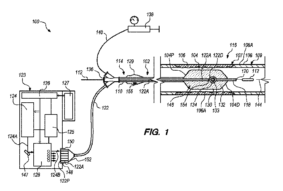
本明細書に開示されるカテーテルシステムは、多くの異なる形態を含むことができる。ここで図1を参照すると、さまざまな実施形態によるカテーテルシステム100の概略断面図が示されている。カテーテルシステム100は、患者の体内の血管の血管壁内の又は血管壁に隣接する1つ又は複数の血管病変に破砕を引き起こすために、圧力波を与えるのに好適である。図1に示される実施形態において、カテーテルシステム100は、カテーテル102と、1つ又は複数の(好ましくは、複数の)光ガイド122Aを含む光ガイドバンドル122と、源マニホールド136と、流体ポンプ138と、光源124、電源125、システムコントローラ126、グラフィックユーザインターフェース127(「GUI」)、及びマルチプレクサ128のうちの1つ又は複数を含むシステムコンソール123と、ハンドル組立体129とのうちの1つ又は複数を含むことができる。或いは、カテーテルシステム100は、図1に関して特に示されて説明されるものよりも多い構成要素又は少ない構成要素を含むことができる。
The catheter systems disclosed herein can include many different configurations. Referring now to FIG. 1, shown is a schematic cross-sectional view of a
カテーテル102は、患者109の身体107の中の血管108の血管壁108A内の又は血管壁108Aに隣接する治療部位106へ移動するように構成される。治療部位106は、たとえば、石灰化した血管病変などの1つ又は複数の血管病変106Aを含むことができる。さらに又は代替的に、治療部位106は、線維性の血管病変などの血管病変106Aを含むことができる。
カテーテル102は、膨張可能バルーン104(時には本明細書では単に「バルーン」と呼ばれる)と、カテーテルシャフト110と、ガイドワイヤ112とを含むことができる。バルーン104は、カテーテルシャフト110に結合することができる。バルーン104は、バルーン近位端104Pと、バルーン遠位端104Dとを含むことができる。カテーテルシャフト110は、カテーテルシステム100の近位部114からカテーテルシステム100の遠位部116まで延在することができる。カテーテルシャフト110は、長手方向軸144を含むことができる。カテーテルシャフト110は、ガイドワイヤ112にわたって移動するように構成されるガイドワイヤ管腔118も含むことができる。本明細書で利用されるように、ガイドワイヤ管腔118は、ガイドワイヤ112が延在する導管を画定する。カテーテルシャフト110は、膨張管腔(図示せず)及び/又はさまざまな他の目的のためのさまざまな他の管腔をさらに含むことができる。いくつかの実施形態において、カテーテル102は、遠位端開口120を有することができ、ガイドワイヤ112を収容することができて、カテーテル102が移動されて、治療部位106に又は治療部位106の近くに位置付けられるとき、ガイドワイヤ112上を追跡することができる。いくつかの実施形態において、バルーン近位端104Pは、カテーテルシャフト110に結合することができ、バルーン遠位端104Dは、ガイドワイヤ管腔118に結合することができる。
バルーン104は、バルーン内部146を画定するバルーン壁130を含む。バルーン104は、患者の脈管構造を通してカテーテル102を進めるのに好適な収縮状態から、治療部位106に対する所定の位置にカテーテル102を固定するのに好適な(図1に示されるような)膨張状態に膨らませるために、バルーン流体132で選択的に膨張させることができる。別の方法で述べると、バルーン104が膨張状態であるとき、バルーン104のバルーン壁130は、治療部位106に、すなわち、治療部位106における血管病変106Aに略隣接して位置付けられるように構成される。図1は、膨張状態であるときに、バルーン104のバルーン壁130が血管108の治療部位106から離間して示されていることを示しているがこれは単に説明を容易にするために行われていることが理解される。バルーン104が膨張状態であるとき、バルーン104のバルーン壁130は、通常、治療部位106に略直接隣接している及び/又は治療部位106に当接していることに留意されたい。
カテーテルシステム100での使用に好適であるバルーン104は、収縮状態であるときに、患者109の脈管構造を通過することができるものを含む。いくつかの実施形態において、バルーン104はシリコーンから作られる。他の実施形態において、バルーン104は、ポリジメチルシロキサン(PDMS)、ポリウレタン、PEBAX(商標)材料などのポリマー、ナイロン、又は、任意の他の好適な材料から作ることができる。
バルーン104は、(膨張状態において)任意の好適な直径を有することができる。さまざまな実施形態において、バルーン104は、1ミリメートル(mm)未満から25mmまでの範囲の(膨張状態における)直径を有することができる。いくつかの実施形態において、バルーン104は、少なくとも1.5mmから14mmまでの範囲の(膨張状態における)直径を有することができる。いくつかの実施形態において、バルーン104は、少なくとも2mmから5mmまでの範囲の(膨張状態における)直径を有することができる。
いくつかの実施形態において、バルーン104は、少なくとも3mm~300mmの範囲の長さを有することができる。より詳細には、いくつかの実施形態において、バルーン104は、少なくとも8mm~200mmの範囲の長さを有することができる。比較的より長い長さを有するバルーン104は、より大きな治療部位106に隣接して位置付けられることができ、よって、治療部位106の中の正確な場所で、より大きな血管病変106A又は複数の血管病変106Aに圧力波を与え、破砕を引き起こすために使用可能であってもよいことが理解される。より長いバルーン104は、いずれか1つの所定の時間に、複数の治療部位106に隣接して位置付けられることもできることがさらに理解される。
In some embodiments,
バルーン104は、約1気圧(atm)~70気圧の膨張圧力まで膨張させることができる。いくつかの実施形態において、バルーン104は、少なくとも20atm~60atmの膨張圧力まで膨張させることができる。他の実施形態において、バルーン104は、少なくとも6atm~20atmの膨張圧力まで膨張させることができる。さらに他の実施形態において、バルーン104は、少なくとも3atm~20atmの膨張圧力まで膨張させることができる。さらに他の実施形態において、バルーン104は、少なくとも2atm~10atmの膨張圧力まで膨張させることができる。
バルーン104は、円錐形状、正方形状、長方形状、球面形状、円錐/正方形状、円錐/球面形状、引き延ばされた球面形状、楕円形状、先細形状、骨形状、段差径形状、オフセット形状、又は円錐状オフセット形状を含むが、これらに限定されない、さまざまな形状を有することができる。いくつかの実施形態において、バルーン104は、薬剤溶出コーティング又は薬剤溶出ステント構造を含むことができる。薬剤溶出コーティング又は薬剤溶出ステントは、抗炎症薬、抗悪性腫瘍薬、抗血管新生薬などを含む1つ又は複数の治療薬を含むことができる。
バルーン流体132は、液体又はガスとすることができる。使用に好適なバルーン流体132のいくつかの例は、水、生理食塩水、造影剤、フルオロカーボン、パーフルオロカーボン、二酸化炭素などのガス、又は任意の他の好適なバルーン流体132のうちの1つ又は複数を含むことができるが、これらに限定されない。いくつかの実施形態において、バルーン流体132が、ベース膨張流体として使用することができる。いくつかの実施形態において、バルーン流体132は、約50:50の体積比の、生理食塩水と造影剤との混合物を含むことができる。他の実施形態において、バルーン流体132は、約25:75の体積比の、生理食塩水と造影剤との混合物を含むことができる。さらに他の実施形態において、バルーン流体132は、約75:25の体積比の、生理食塩水と造影剤との混合物を含むことができる。しかしながら、生理食塩水と造影剤との任意の好適な比率を使用することができることが理解される。バルーン流体132は、圧力波の移動速度が適切に操作されるように、組成物、粘度などに基づいて調整することができる。ある実施形態において、本明細書での使用に好適なバルーン流体132は生体適合性である。バルーン流体132の体積は、選択された光源124及び使用されるバルーン流体132の種類によって調整することができる。
いくつかの実施形態において、造影剤で使用されるコントラスト剤は、イオン性又は非イオン性ヨウ素系コントラスト剤などのヨウ素系コントラスト剤を含むことができるが、これらに限定されるものではない。イオン性ヨウ素系コントラスト剤のいくつかの非限定的な例は、ジアトリゾ酸、メトリゾ酸、イオタラム酸、及びイオキサグル酸を含む。非イオン性ヨウ素系コントラスト剤のいくつかの非限定的な例は、イオパミドール、イオヘキソール、イオキシラン、イオプロミド、イオジキサノール、及びイオベルソールを含む。他の実施形態において、非ヨウ素系コントラスト剤を使用することができる。好適なヨウ素を含有しないコントラスト剤は、ガドリニウム(III)系コントラスト剤を含むことができる。好適なフルオロカーボン及びパーフルオロカーボン薬剤は、パーフルオロカーボンドデカフルオロペンタン(DDFP、C5F12)などの薬剤を含むことができるが、これらに限定されるものではない。 In some embodiments, contrast agents used in imaging agents can include, but are not limited to, iodine-based contrast agents, such as ionic or non-ionic iodine-based contrast agents. Some non-limiting examples of ionic iodine-based contrast agents include diatrizoic acid, metrizoic acid, iothalamic acid, and ioxaglic acid. Some non-limiting examples of non-ionic iodinated contrast agents include iopamidol, iohexol, ioxirane, iopromide, iodixanol, and ioversol. In other embodiments, non-iodine contrast agents can be used. Suitable non-iodine-containing contrast agents can include gadolinium(III)-based contrast agents. Suitable fluorocarbon and perfluorocarbon agents can include, but are not limited to, agents such as perfluorocarbon dodecafluoropentane (DDFP, C5F12).
バルーン流体132は、電磁スペクトルの紫外領域(たとえば、少なくとも10ナノメートル(nm)~400nm)、可視領域(たとえば、少なくとも400nm~780nm)、又は近赤外領域(たとえば、少なくとも780nm~2.5μm)の光を選択的に吸収することができる吸収剤を含むものを含むことができる。好適な吸収剤は、少なくとも10nm~2.5μmのスペクトルに沿った吸収極大を有するものを含むことができる。或いは、バルーン流体132は、電磁スペクトルの中赤外領域(たとえば、少なくとも2.5μm~15μm)又は遠赤外領域(たとえば、少なくとも15μm~1mm)の光を選択的に吸収することができる吸収剤を含むことができる。さまざまな実施形態において、吸収剤は、カテーテルシステム100で使用されるレーザの発光極大と適合する吸収極大を有するものとすることができる。非限定的な例として、本明細書に記載されるさまざまなレーザは、ネオジム:イットリウムアルミニウムガーネット(Nd:YAG、発光極大=1064nm)レーザ、ホルミウム:YAG(Ho:YAG、発光極大=2.1μm)レーザ、又は、エルビウム:YAG(Er:YAG、発光極大=2.94μm)レーザを含むことができる。いくつかの実施形態において、吸収剤は水溶性とすることができる。他の実施形態において、吸収剤は水溶性ではない。いくつかの実施形態において、バルーン流体132で使用される吸収剤は、光源124のピーク発光に適合するように調整することができる。少なくとも10ナノメートル~1ミリメートルの発光波長を有するさまざまな光源124が、本明細書の他の場所で論じられる。
カテーテル102のカテーテルシャフト110は、光源124と光連通する光ガイドバンドル122の1つ又は複数の光ガイド122Aに結合することができる。光ガイド122Aは、カテーテルシャフト110に沿って、バルーン104内に配設することができる。光ガイド122Aのそれぞれは、バルーン104の長さに対して任意の好適な長手方向の位置にあるガイド遠位端122Dを有することができる。いくつかの実施形態において、各光ガイド122Aは光ファイバーとすることができ、光源124はレーザとすることができる。光源124は、カテーテルシステム100の近位部114で、光ガイド122Aと光連通することができる。より詳細には、本明細書で詳細に説明されるように、光源124は、マルチプレクサ128の存在及び動作のために、選択的に、同時に、順次、及び/又は代替的に、任意の望ましい組合せ、順序、及び/又はパターンで光ガイド122Aのそれぞれと光連通することができる。
いくつかの実施形態において、カテーテルシャフト110は、第1の光ガイド、第2の光ガイド、第3の光ガイドなどの複数の光ガイド122Aに結合することができ、それは、ガイドワイヤ管腔118及び/又はカテーテルシャフト110のまわりの任意の好適な位置に配設することができる。たとえば、ある非排他的な実施形態において、2つの光ガイド122Aは、ガイドワイヤ管腔118及び/又はカテーテルシャフト110の周囲で、約180度離間させることができる。3つの光ガイド122Aは、ガイドワイヤ管腔118及び/又はカテーテルシャフト110の周囲で、約120度離間させることができる。又は、4つの光ガイド122Aは、ガイドワイヤ管腔118及び/又はカテーテルシャフト110の周囲で、約90度離間させることができる。さらに代替的に、複数の光ガイド122Aは、ガイドワイヤ管腔118及び/又はカテーテルシャフト110の周囲で、互いから均等に離間させる必要はない。より詳細には、光ガイド122Aは、望ましい場所での望ましい効果を実現するために、ガイドワイヤ管腔118及び/又はカテーテルシャフト110の周囲で均等又は不均等のいずれでも配設することができる。
In some embodiments, the
カテーテルシステム100及び/又は光ガイドバンドル122は、近位部114で光源124と光連通し、遠位部116のバルーン104のバルーン内部146のバルーン流体132と光連通する任意の数の光ガイド122Aを含むことができる。たとえば、いくつかの実施形態において、カテーテルシステム100及び/又は光ガイドバンドル122は、1~5個の光ガイド122Aを含むことができる。他の実施形態において、カテーテルシステム100及び/又は光ガイドバンドル122は、5~15個の光ガイド122Aを含むことができる。さらに他の実施形態において、カテーテルシステム100及び/又は光ガイドバンドル122は、10~30個の光ガイド122Aを含むことができる。或いは、さらに他の実施形態において、カテーテルシステム100及び/又は光ガイドバンドル122は、30個より多い光ガイド122Aを含むことができる。
光ガイド122Aは、バルーン内部146のバルーン流体132においてプラズマ及び/又は圧力波を発生させるために、任意の好適な設計を有することができる。ある実施形態において、光ガイド122Aは、光ファイバー又は可撓性ライトパイプを含むことができる。光ガイド122Aは、薄く、可撓性とすることができ、強度のごくわずかな損失で光信号を送信することができる可能性がある。光ガイド122Aは、その周囲をクラッドによって囲まれるコアを含むことができる。いくつかの実施形態において、コアは、円筒形のコア又は部分的に円筒形のコアとすることができる。光ガイド122Aのコア及びクラッドは、1つ又は複数の種類のガラス、シリカ、又は1つ又は複数のポリマーを含むがこれらに限定されない1つ又は複数の材料から形成することができる。光ガイド122Aは、ポリマーなどの保護被膜も含んでもよい。コアの屈折率はクラッドの屈折率より大きいであろうことが理解される。
各光ガイド122Aは、ガイド近位端122Pから、バルーン内部146に位置付けられる少なくとも1つの光窓(図示せず)を有するガイド遠位端122Dまで、その長さに沿って光エネルギーを案内することができる。
Each
光ガイド122Aは、カテーテル102のカテーテルシャフト110のまわりに及び/又はそれに対して多くの構成を考えることができる。いくつかの実施形態において、光ガイド122Aは、カテーテルシャフト110の長手方向軸144と平行に走ることができる。いくつかの実施形態において、光ガイド122Aは、カテーテルシャフト110に物理的に結合することができる。他の実施形態において、光ガイド122Aは、カテーテルシャフト110の外径の長さに沿って配設することができる。さらに他の実施形態において、光ガイド122Aは、カテーテルシャフト110の中の1つ又は複数の光ガイド管腔内に配設することができる。
光ガイド122Aは、ガイドワイヤ管腔118及び/又はカテーテルシャフト110の周囲の任意の好適な位置にも配設することができ、光ガイド122Aのそれぞれのガイド遠位端122Dは、治療部位106における血管病変106Aを破壊するために圧力波をより効果的に且つ正確に与えるために、バルーン104の長さに対して及び/又はガイドワイヤ管腔118の長さに対して、任意の好適な長手方向の位置に配設することができる。
The light guides 122A can also be disposed in any suitable location around the
ある実施形態において、光ガイド122Aは、1つ又は複数の光音響トランスデューサ154を含むことができ、ここで、各光音響トランスデューサ154は、それが配設される光ガイド122Aと光連通することができる。いくつかの実施形態において、光音響トランスデューサ154は、光ガイド122Aのガイド遠位端122Dと光連通することができる。さらに、このような実施形態において、光音響トランスデューサ154は、光ガイド122Aのガイド遠位端122Dと対応する及び/又はそれに一致する形状を有することができる。
In some embodiments, the
光音響トランスデューサ154は、光ガイド122Aのガイド遠位端122Dで又はその近くで、光エネルギーを音波に変換するように構成される。音波の方向は、光ガイド122Aのガイド遠位端122Dの角度を変えることによって調整することができる。
ある実施形態において、光ガイド122Aのガイド遠位端122Dに配設される光音響トランスデューサ154は、光ガイド122Aのガイド遠位端122Dと同じ形状を考えることができる。たとえば、ある非排他的な実施形態において、光音響トランスデューサ154及び/又はガイド遠位端122Dは、円錐形状、凸形状、凹形状、球根状形状、正方形状、階段状形状、半円形状、卵形形状などを有することができる。光ガイド122Aは、光ガイド122Aの長さの1つ又は複数の側面に沿って配設される追加の光音響トランスデューサ154をさらに含むことができる。
In some embodiments, the
いくつかの実施形態において、光ガイド122Aは、光ガイド122Aのガイド遠位端122Dで又はその近くに位置することができる側面の方へ、及び、バルーン壁130の方へ、光ガイド122Aを出るために光エネルギーを導くように構成される光ガイド122A内に1つ又は複数のダイバーティング特徴部、すなわち「ダイバータ」(図1に示されない)をさらに含むことができる。ダイバーティング特徴部は、光ガイド122Aから、その軸方向経路から離れて、光ガイド122Aの側面の方へ光エネルギーの向きを変えるシステムの任意の特徴部を含むことができる。さらに、光ガイド122Aはそれぞれ、各光ガイド122Aの長手方向又は周囲の表面に沿って配設され、ダイバーティング特徴部と光連通する1つ又は複数の光窓を含むことができる。別の方法で述べると、ダイバーティング特徴部は、ガイド遠位端122Dに又はその近くにある側面の方へ光ガイド122Aの光エネルギーを導くように構成することができ、ここで、側面は光窓と光連通する。光窓は、光ガイド122Aの上又はそのまわりの被覆材がない光ガイド122Aの部分などの、光エネルギーが光ガイド122A内から光ガイド122Aを出ることを可能にする光ガイド122Aの部分を含むことができる。
In some embodiments, the
使用に好適なダイバーティング特徴部の例は、反射素子、屈折素子、及びファイバーディフューザを含む。光ガイド122Aの先端から離れる光エネルギーを集束させるために好適であるダイバーティング特徴部は、凸面、屈折率分布(GRIN)レンズ、及び鏡像焦点レンズを有するものを含むことができるが、これらに限定されるものではない。ダイバーティング特徴部との接触時、光エネルギーは、光ガイド122Aの側面と光連通するプラズマジェネレータ133及び光音響トランスデューサ154のうちの1つ又は複数へと、光ガイド122A内で向きを変えられる。記載したように、次いで、光音響トランスデューサ154は、光エネルギーを、光ガイド122Aの側面から離れて広がる音波に変換する。
Examples of diverting features suitable for use include reflective elements, refractive elements, and fiber diffusers. Diverting features suitable for focusing light energy away from the tip of
源マニホールド136は、カテーテルシステム100の近位部114に又はその近くに位置付けることができる。源マニホールド136は、光ガイドバンドル122の1つ若しくは複数の光ガイド122A、ガイドワイヤ112、及び/又は、流体ポンプ138と流体連通して結合される膨張導管140を受けることができる1つ又は複数の近位端開口を含むことができる。カテーテルシステム100は、必要に応じて、バルーン流体132で、すなわち、膨張導管140を介して、バルーン104を膨張するように構成される流体ポンプ138も含むことができる。
上記のように、図1に示される実施形態において、システムコンソール123は、光源124、電源125、システムコントローラ126、GUI127、及びマルチプレクサ128のうちの1つ又は複数を含む。或いは、システムコンソール123は、特に図1に示されるものより多い構成要素又は少ない構成要素を含むことができる。たとえば、ある非排他的な代替の実施形態において、システムコンソール123は、GUI127なしで設計することができる。さらに代替的に、光源124、電源125、システムコントローラ126、GUI127、及びマルチプレクサ128のうちの1つ又は複数は、システムコンソール123の特定の必要性なしに、カテーテルシステム100内に設けることができる。
As noted above, in the embodiment shown in FIG. 1,
示されるように、システムコンソール123及びそれとともに含まれる構成要素は、カテーテルシステム100のカテーテル102、光ガイドバンドル122、及び残りの部分に動作可能に結合される。たとえば、いくつかの実施形態において、図1に示されるように、システムコンソール123は、光ガイドバンドル122がシステムコンソール123に機械的に結合されるコンソール接続開口部148(時には概して「ソケット」とも呼ばれる)を含むことができる。このような実施形態において、光ガイドバンドル122は、光ガイド122Aのそれぞれの部分、たとえば、ガイド近位端122Pを収容するガイド結合ハウジング150(時には概して「フェルール」とも呼ばれる)を含むことができる。ガイド結合ハウジング150は、光ガイドバンドル122とシステムコンソール123との間の機械的結合を提供するために、コンソール接続開口部148内に嵌合して、選択的に保持されるように構成される。
As shown,
光ガイドバンドル122は、光ガイド122A及び/又は光ガイドバンドル122をカテーテルシステム100の使用中にカテーテル102とともに血管108に延在するときによりコンパクトな形態とすることができるように、個々の光ガイド122Aのそれぞれをより近くにまとめるガイドバンドラ152(又は、「シェル」)も含むことができる。
Light guide bundles 122 are separated into individual light guides so that
光源124は、光ガイドバンドル122の光ガイド122Aのそれぞれ、すなわち、光ガイド122Aのそれぞれのガイド近位端122Pと光連通して、選択的に及び/又は代替的に結合することができる。特に、光源124は、任意の望ましい組合せ、順番、順序、及び/又はパターンで、光ガイドバンドル122の光ガイド122Aのそれぞれに選択的に及び/又は代替的に導き、それで受けることができるパルス源ビームなどの源ビーム124Aの形態で光エネルギーを発生させるように構成される。より詳細には、本明細書の以下でより詳細に説明されるように、光源124からの源ビーム124Aは、マルチプレクサ128を通して導かれ、個々のガイドビーム124B(すなわち、「多重ビーム」)は、光ガイドバンドル122の光ガイド122Aのそれぞれに選択的に及び/又は代替的に導き、それで受けることができる。特に、光源124の各パルス、すなわち、源ビーム124Aの各パルスは、光ガイドバンドル122の光ガイド122Aの1つ又は複数に選択的に及び/又は代替的に導かれる1つ又は複数の別個のガイドビーム124B(図1に1つのみ示されている)を発生させるために、マルチプレクサ128を通して導くことができる。
The
光源124は、任意の好適な設計を有することができる。ある実施形態において、光源124は、光ガイド122Aのガイド近位端122Pに結合するために、小さい点に集束する光源124から光エネルギーのサブミリ秒のパルスを提供するように構成することができる。次いで、エネルギーのそのようなパルスは、光ガイド122Aに沿って、バルーン104のバルーン内部146の場所に導かれ及び/又は案内され、それによって、バルーン104のバルーン内部146のバルーン流体132において、たとえば、光ガイド122Aのガイド遠位端122Dに位置することができるプラズマジェネレータ133を介して、プラズマ形成を引き起こす。特に、光ガイド122Aのガイド遠位端122Dで放出される光は、バルーン内部146のバルーン流体132内でプラズマを形成するために、プラズマジェネレータ133にエネルギーを与える。プラズマ形成は、急激なバブル形成を引き起こし、治療部位106に圧力波を与える。例示的なプラズマ誘起バブル134は、図1に示される。
さまざまな非排他的な代替の実施形態において、光源124からの光エネルギーのサブミリ秒のパルスは、約1ヘルツ(Hz)~5000Hz、約30Hz~1000Hz、約10Hz~100Hz、又は、約1Hz~30Hzの周波数で、治療部位106に送達することができる。或いは、光エネルギーのサブミリ秒のパルスは、5000Hzより大きい若しくは1Hz未満より小さくすることができる周波数で、又は、任意の他の好適な範囲の周波数で、治療部位106に送達することができる。
In various non-exclusive alternative embodiments, the sub-millisecond pulses of light energy from
通常は、光源124が光エネルギーのパルスを提供するために利用されるが、光源124は、単一の源ビーム124A、すなわち、単一のパルス源ビームを提供するとしてさらに記載することができることが理解される。
Although
本明細書での使用に好適な光源124は、レーザ及びランプを含むさまざまな光源を含むことができる。好適なレーザは、サブミリ秒のタイムスケールのショートパルスレーザを含むことができる。いくつかの実施形態において、光源124は、ナノ秒(ns)のタイムスケールのレーザを含むことができる。レーザは、ピコ秒(ps)、フェムト秒(fs)、及びマイクロ秒(μs)のタイムスケールのショートパルスレーザも含むことができる。カテーテル102のバルーン流体132内のプラズマを実現するために採用することができるレーザ波長、パルス幅、及びエネルギーレベルの多くの組合せがあることが理解される。さまざまな非排他的な代替の実施形態において、パルス幅は、少なくとも10ns~3000ns、少なくとも20ns~100ns、又は、少なくとも1ns~500nsを含む範囲内にあるものを含むことができる。或いは、任意の他の好適なパルス幅範囲を使用することができる。
例示的なナノ秒レーザは、UV~IRスペクトル内のものを含むことができ、約10ナノメートル(nm)~1ミリメートル(mm)の波長にわたる。いくつかの実施形態において、カテーテルシステム100での使用に好適な光源124は、少なくとも750nm~2000nmの波長で光を発することが可能なものを含むことができる。他の実施形態において、光源124は、少なくとも700nm~3000nmの波長で光を発することが可能なものを含むことができる。さらに他の実施形態において、光源124は、少なくとも100nm~10マイクロメートル(μm)の波長で光を発することが可能なものを含むことができる。ナノ秒レーザは、最大200kHzの繰り返し数を有するものを含むことができる。いくつかの実施形態において、レーザは、Qスイッチツリウム:イットリウムアルミニウムガーネット(Tm:YAG)レーザを含むことができる。他の実施形態において、レーザは、ネオジム:イットリウムアルミニウムガーネット(Nd:YAG)レーザ、ホルミウム:イットリウムアルミニウムガーネット(Ho:YAG)レーザ、エルビウム:イットリウムアルミニウムガーネット(Er:YAG)レーザ、エキシマレーザ、ヘリウムネオンレーザ、二酸化炭素レーザ、並びに、ドープされたパルスファイバーレーザを含むことができる。
Exemplary nanosecond lasers can include those in the UV-IR spectrum and span wavelengths from about 10 nanometers (nm) to 1 millimeter (mm). In some embodiments,
カテーテルシステム100は、少なくとも1メガパスカル(MPa)~100MPaの範囲の最大圧力を有する圧力波を発生させることができる。特定のカテーテルシステム100によって発生する最大圧力は、光源124、吸収材料、バブル膨張、伝播媒体、バルーン材料、及び他の要因に依存する。さまざまな非排他的な代替の実施形態において、カテーテルシステム100は、少なくとも約2MPa~50MPa、少なくとも約2MPa~30MPa、又は、少なくとも約15MPa~25MPaの範囲の最大圧力を有する圧力波を発生させることができる。
The
圧力波は、カテーテル102が治療部位106に置かれたときに、エネルギーガイド122Aから半径方向に伸びる少なくとも約0.1ミリメートル(mm)から約25mmを超える範囲内の距離から治療部位106に与えることができる。さまざまな非排他的な代替の実施形態において、圧力波は、カテーテル102が治療部位106に置かれたときに、エネルギーガイド122Aから半径方向に伸びる少なくとも約10mm~20mm、少なくとも約1mm~10mm、少なくとも約1.5mm~4mm、又は、少なくとも約0.1mm~10mmの範囲内の距離から治療部位106に与えられることができる。他の実施形態において、圧力波は、前述の範囲とは異なる別の好適な距離から治療部位106に与えることができる。いくつかの実施形態において、圧力波は、少なくとも約0.1mm~10mmの距離で、少なくとも約2MPa~30MPaの範囲内で、治療部位106に与えることができる。いくつかの実施形態において、圧力波は、少なくとも約0.1mm~10mmの距離で、少なくとも約2MPa~25MPaの範囲から、治療部位106に与えることができる。さらに代替的に、他の好適な圧力範囲及び距離を使用することができる。
The pressure waves are applied to the
電源125は、光源124、システムコントローラ126、GUI127、マルチプレクサ128、及びハンドル組立体129のそれぞれに電気的に結合されて、必要な電力を供給するように構成される。電源125は、そのような目的のための任意の好適な設計を有することができる。
システムコントローラ126は、電源125に電気的に結合されて、電源125から電力を受け取る。さらに、システムコントローラ126は、光源124、GUI127、及びマルチプレクサ128のそれぞれに結合され、それぞれの動作を制御するように構成される。システムコントローラ126は、少なくとも、光源124、GUI127、及びマルチプレクサ128の動作を制御することのために、1つ又は複数のプロセッサ又は回路を含むことができる。たとえば、システムコントローラ126は、要望通り、及び/又は、任意の望ましい発射レートで光エネルギーのパルスを発生させるために、光源124を制御することができる。その後、次いで、システムコントローラ126は、マルチプレクサ128を制御することができ、光源124、すなわち、源ビーム124Aからの光エネルギーは、望ましい方法で個々のガイドビーム124Bの形態で光ガイド122Aのそれぞれに選択的に及び/又は代替的に導かれるように、効果的に且つ正確に多重化することができる。
システムコントローラ126はさらに、治療部位106に隣接するカテーテル102の位置決め、バルーン流体132によるバルーン104の膨張などの、カテーテルシステム100の他の構成要素の動作を制御するように構成することができる。さらに又は代替的に、カテーテルシステム100は、カテーテルシステム100のさまざまな動作を制御するために、任意の好適な方法で位置付けることができる1つ又は複数の追加のコントローラを含むことができる。たとえば、ある実施形態において、追加のコントローラ及び/又はシステムコントローラ126の一部は、ハンドル組立体129内に位置付けることができる、及び/又は、組み込むことができる。
GUI127は、カテーテルシステム100のユーザ又は操作者がアクセス可能である。さらに、GUI127は、システムコントローラ126に電気的に接続される。そのような設計により、GUI127は、カテーテルシステム100が治療部位106の血管病変106Aに圧力を与えて破砕を引き起こすために効果的に利用されることを確実にするために、ユーザ又は操作者が使用することができる。GUI127は、ユーザ又は操作者に、カテーテルシステム100の使用前、使用中、及び使用後に使用することができる情報を提供することができる。1つの実施形態において、GUI127は、静的な視覚データ及び/又は情報をユーザ又は操作者に提供することができる。加えて又は代替的に、GUI127は、カテーテルシステム100の使用中、時間が経つにつれて変わるビデオデータ又は任意の他のデータなどの動的な視覚データ及び/又は情報を、ユーザ又は操作者に提供することができる。さまざまな実施形態において、GUI127は、ユーザ又は操作者への警報の働きをしてもよい、1つ又は複数の色、異なる寸法、変化する明度などを含むことができる。さらに又は代替的に、GUI127は、オーディオデータ又は情報をユーザ又は操作者に提供することができる。GUI127の詳細は、カテーテルシステム100の設計要求、すなわち、特定ニーズ、仕様、及び/又はユーザ若しくは操作者の要望に応じて変えることができる。
本明細書で提供されるように、マルチプレクサ128は、光源124からの光エネルギーを光ガイドバンドル122の光ガイド122Aのそれぞれに選択的に及び/又は代替的に導くように構成される。より詳細には、マルチプレクサ128は、単一の光源124からの光エネルギー、たとえば、単一のレーザ源からの単一の源ビーム124Aを受け取り、個々のガイドビーム124Bの形態のそのような光エネルギーを、任意の望ましい組合せ(すなわち、複数の光ガイド122Aを通して光エネルギーを同時に導く)、順序、順番、及び/又はパターンで、光ガイドバンドル122の光ガイド122Aのそれぞれに選択的に及び/又は代替的に導くように構成される。よって、マルチプレクサ128は、単一の光源124を、複数の光ガイド122Aを通して同時に及び/又は順次、送ることを可能にし、それにより、カテーテルシステム100は、望ましい方法で、血管108の血管壁108A内の又は血管壁108Aに隣接する治療部位106における血管病変に圧力を与えて、血管病変に破砕を引き起こすことができる。さらに、示されるように、カテーテルシステム100は、源ビーム124Aの形態の光エネルギーを、光源124からマルチプレクサ128まで導くために、1つ又は複数の光学素子147を含むことができる。
As provided herein,
マルチプレクサ128は、光エネルギーを、光源124から光ガイドバンドル122の光ガイド122Aのそれぞれまで選択的に及び/又は代替的に導くために、任意の好適な設計を有することができる。マルチプレクサ128のさまざまな非排他的な代替の実施形態は、図2~23に関して以下で、本明細書で詳細に説明される。
図1に示されるように、ハンドル組立体129は、カテーテルシステム100の近位部114に若しくはその近くに、及び/又は、源マニホールド136の近くに位置付けることができる。本実施形態において、ハンドル組立体129は、バルーン104に結合され、バルーン104から離間して位置付けられる。或いは、ハンドル組立体129は、別の好適な場所に位置付けることができる。
As shown in FIG. 1, handle
ハンドル組立体129が、カテーテル102の作動、位置決め、及び制御を行うために、ユーザ又は操作者によって取り扱われて、使用される。ハンドル組立体129の設計及び特定の特徴は、カテーテルシステム100の設計要求に適合するように変えることができる。図1に示される実施形態において、ハンドル組立体129は、システムコントローラ126、光源124、流体ポンプ138、GUI127、及びマルチプレクサ128のうちの1つ又は複数から離れているが、電気及び/又は流体連通している。いくつかの実施形態において、ハンドル組立体129は、システムコントローラ126の少なくとも一部をハンドル組立体129の内部に一体化できる、及び/又は、含むことができる。たとえば、示されるように、あるこのような実施形態において、ハンドル組立体129は、システムコントローラ126の少なくとも一部を形成することができる回路156を含むことができる。1つの実施形態において、回路155は、1つ又は複数の集積回路又は任意の他の好適な回路を有するプリント回路基板を含むことができる。代替的な実施形態において、回路155は、省略することができる、又は、さまざまな実施形態において、ハンドル組立体129の外側に、たとえば、システムコンソール123内に位置付けることができるシステムコントローラ126内に含めることができる。ハンドル組立体129は、特に示されて、本明細書に記載されたものより少ない構成要素、又は、追加の構成要素を含むことができることが理解される。
A
図2は、マルチプレクサ228のある実施形態を含むカテーテルシステム200のある実施形態の一部の簡略化された概略図である。特に、図2は、複数の光ガイド222Aを含む光ガイドバンドル222と、(図1に示される)光源124から、源ビーム224A、さまざまな実施形態ではパルス源ビーム224Aの形態の光エネルギーを受け取り、個々のガイドビーム224Bの形態の光エネルギーを、複数の光ガイド222Aのうちの少なくとも2つに同時に及び/又は順次、導くマルチプレクサ228とを示す。より詳細には、マルチプレクサ228は、複数の光ガイド222Aのうちの少なくとも2つのガイド近位端222P上に、個々のガイドビーム224Bの形態の光エネルギーを導くように構成される。よって、図2に示されるように、マルチプレクサ228は、光ガイドバンドル222に及び/又は複数の光ガイド222Aに光連通して、動作可能に及び/又は光学的に結合される。
FIG. 2 is a simplified schematic diagram of a portion of an embodiment of catheter system 200 including an embodiment of
光ガイドバンドル222は、任意の好適な数の光ガイド222Aを含むことができ、それらは、マルチプレクサ228に対して複数の光ガイド222Aを最もよく位置合わせする任意の好適な方法で、互いに対して位置付ける及び/又は方向付けることができることが理解される。たとえば、図2に示される実施形態において、光ガイドバンドル222は、互いに対して直線配置で位置合わせされる4つの光ガイド222Aを含む。光ガイドバンドル222及び/又は光ガイド222Aは、本明細書において上で詳細に説明された設計及び機能に略類似している。したがって、このような構成要素は、図2に示される実施形態に関して詳細には説明されない。
マルチプレクサ228の設計は、カテーテルシステム200の要件、光ガイド222Aの相対位置に応じて、及び/又は、カテーテルシステム200のユーザ又は操作者の要求を満たすために、変えることができる。図2に示される実施形態において、マルチプレクサ228は、多面プリズム256及び結合光学部品258のうちの1つ又は複数を含む。或いは、マルチプレクサ228は、特に図2に示されるものより多い構成要素又は少ない構成要素を含むことができる。
The design of
多面プリズム256は、特定の角度で複数のファセットを有する、研磨されたガラス板からなる。多面プリズム256は、源ビーム224Aを、それぞれが光ガイドバンドル222の複数の光ガイド222Aのうちの1つに結合することができる複数の個々のガイドビーム224Bに分割することができる。より詳細には、源ビーム224Aが多面プリズム256の頂点256Vに集中するように、多面プリズムが源ビーム224Aに対して位置付けられる場合、多面プリズム256は、平行源ビーム224Aを複数の個々のガイドビーム224Bに等分に分割することができる。このような設計によって、平行源ビーム224Aが多面プリズム256を通過するとき、多面プリズム256は、源ビーム224Aを、伝播方向の軸のまわりで異なる角度を有する、略等しいエネルギーの複数のガイドビーム224Bに分割する。これにより、単一の光源124からの光エネルギーを、同じ平面に位置するガイド近位端222Pを有する、平行な光ガイド222Aのアレイに結合させることができる。
The
源ビーム224Aは、多面プリズム256内に含まれるファセットの数に応じて、2つ以上の個々のガイドビーム224Bに分割されることが理解される。たとえば、図2に示される実施形態において、多面プリズム256は、源ビーム224Aが2つの個々のガイドビーム224Bに分割されるような2つのファセットを含む。特に、本実施形態において、源ビーム224Aは、プリズム面上での屈折によって定義される角度で交差する2つの「半円」ガイドビーム224Bへと2つに分割される。或いは、多面プリズム256は、源ビーム224Aが2つより多いガイドビーム224Bに分割されるように、2つより多いファセットを含むことができる。
It is understood that the
その後、個々のガイドビーム224Bは、結合光学部品258に導かれる。結合光学部品258は、個々のガイドビーム224Bを光ガイド222Aのうちの少なくとも2つに集束させるために、任意の好適な設計を有することができる。1つの実施形態において、結合光学部品258は、要望通り、個々のガイドビーム224Bを集束させるように特に構成された単一の集束レンズを含む。2つの同一平面上の非平行ガイドビーム224Bが単レンズに入射する場合、単レンズの形態の結合光学部品258の焦点における結果は、ガイドビーム224Bとレンズの焦点距離との間の角度に関連するオフセットを有する2つの焦点スポットであろう。より詳細には、個々のガイドビーム224Bが結合光学部品258の単一の集束レンズを通過するとき、結合光学部品258は、焦点面で円形の複数の点にガイドビームを集束させる。よって、光ガイド222Aが焦点面の焦点スポットと位置合わせされると、光は、複数の光ガイド222Aに結合する。したがって、角度及びレンズは、2つのガイドビーム224Bが平行な光ガイド222Aの任意の組に効果的に結合されることを可能にするように選択することができることが理解される。或いは、結合光学部品258は、別の好適な設計を有することができる。
Individual guide beams 224 B are then directed to combining
この方法の利点は、源ビーム224Aを分割することに関する公差が主に、多面プリズム256及び結合光学部品258の光学製作によって制御されることである。しかしながら、主な例外は、源ビーム224Aの光エネルギーの等しい分割を保証するために、源ビーム224Aに対して多面プリズム256を正確に位置付ける必要性である。
An advantage of this method is that the tolerances for splitting
図3は、マルチプレクサ328の別の実施形態を含むカテーテルシステム300の別の実施形態の一部の簡略化された概略図である。特に、図3は、複数の光ガイド322Aを含む光ガイドバンドル322と、(図1に示される)光源124から、源ビーム324A、さまざまな実施形態ではパルス源ビーム324Aの形態の光エネルギーを受け取り、個々のガイドビーム324Bの形態の光エネルギーを、複数の光ガイド322Aのうちの少なくとも2つのガイド近位端322P上に同時に及び/又は順次、導くマルチプレクサ328とを示す。よって、図3に示されるように、マルチプレクサ328は、光ガイドバンドル322に及び/又は複数の光ガイド322Aに光連通して、動作可能に及び/又は光学的に結合される。
FIG. 3 is a simplified schematic diagram of a portion of another embodiment of
光ガイドバンドル322は、任意の好適な数の光ガイド322Aを含むことができ、それらは、マルチプレクサ328に対して複数の光ガイド322Aを最もよく位置合わせする任意の好適な方法で、互いに対して位置付ける及び/又は方向付けることができることが理解される。たとえば、図3に示される実施形態において、光ガイドバンドル322は、互いに対して略円形の配置で位置合わせされる8つの光ガイド322Aを含む。光ガイドバンドル322及び/又は光ガイド322Aは、本明細書において上で詳細に説明された設計及び機能に略類似している。したがって、このような構成要素は、図3に示される実施形態に関して詳細には説明されない。
本実施形態において、マルチプレクサ328は、図2に関して示されて説明された実施形態といくらか類似している。特に、マルチプレクサ328も、第1の多面プリズム356Aと、結合光学部品358とを含む。しかしながら、本実施形態において、マルチプレクサ328は、第1の多面プリズム356Aと結合光学部品358との間のビーム経路に位置付けられる第2の多面プリズム356Bをさらに含む。
In this embodiment,
前述の実施形態と同様に、源ビーム324Aが第1の多面プリズム356Aの頂点356Vに集中するとき、第1の多面プリズム356Aは、源ビーム324Aを2つの等しい個々のビームに分割する2面プリズムとすることができる。その後、2つの個々のビームは、第2の多面プリズム356Bを通して導かれる。本実施形態において、第2の多面プリズム356Bも2面プリズムであり、第1の多面プリズム356Aからの2つの個々のビームはそれぞれ、源ビーム324Aが4つの個々のガイドビーム324Bを提供するようにここで2回分割されるように分割される。1つの実施形態において、第2の多面プリズム356Bは、第1の多面プリズム356Aに対して、たとえば、約90度回転させることができ、4つの個々のガイドビーム324Bは、結合光学部品358によって集束させられるとき、互いに対して略四角いパターンで配置される。このような設計によって、4つの個々のガイドビーム324Bは、光ガイドバンドル322内に含まれる8つの光ガイド322Aのうちの4つのガイド近位端322P上に効果的に導くことができる。或いは、個々のガイドビーム324Bを光ガイドバンドル322内の光ガイドの異なる対向する組の方へ導くために、第2の多面プリズム356Bは、第1の多面プリズム356Aに対して異なる量だけ、すなわち、約90度より大きく又は小さく回転させることができることが理解される。さらに代替的に、第1の多面プリズム356A及び第2の多面プリズム356Bのそれぞれは、源ビーム324Aを4つより多い個々のガイドビーム324Bに分割することができるように、2つより多いファセットを有することができる。
Similar to the previous embodiment, when the
前述の実施形態と同様に、結合光学部品358は、4つの個々のガイドビーム324Bを、光ガイド322Aのうちの4つに集束させるために、任意の好適な設計を有することができる。1つの実施形態において、結合光学部品358も、要望通り、個々のガイドビーム324Bを集束させるように特に構成される単一の集束レンズを含むことができる。或いは、結合光学部品358は、別の好適な設計を有することができる。
As with the previous embodiments, the
図4は、マルチプレクサ428のさらに別の実施形態を含むカテーテルシステム400のさらに別の実施形態の一部の簡略化された概略図である。特に、図4は、複数の光ガイド422Aを含む光ガイドバンドル422と、(図1に示される)光源124から、源ビーム424A、さまざまな実施形態ではパルス源ビーム424Aの形態の光エネルギーを受け取り、個々のガイドビーム424Bの形態の光エネルギーを、複数の光ガイド422Aのうちの少なくとも2つのガイド近位端422P上に同時に及び/又は順次、導くマルチプレクサ428とを示す。よって、図4に示されるように、マルチプレクサ428は、光ガイドバンドル422に及び/又は複数の光ガイド422Aに光連通して、動作可能に及び/又は光学的に結合される。
FIG. 4 is a simplified schematic diagram of a portion of yet another embodiment of
光ガイドバンドル422は、任意の好適な数の光ガイド422Aを含むことができ、それらは、マルチプレクサ428に対して複数の光ガイド422Aを最もよく位置合わせする任意の好適な方法で、互いに対して位置付ける及び/又は方向付けることができることが理解される。たとえば、図4に示される実施形態において、光ガイドバンドル422も、互いに対して略円形の配置で位置合わせされる8つの光ガイド422Aを含む。光ガイドバンドル422及び/又は光ガイド422Aは、本明細書において上で詳細に説明された設計及び機能に略類似している。したがって、このような構成要素は、図4に示される実施形態に関して詳細には説明されない。
本実施形態において、マルチプレクサ428は、図2に関して示されて説明された実施形態といくらか類似している。特に、マルチプレクサ428も、多面プリズム456と、結合光学部品458とを含む。しかしながら、本実施形態において、多面プリズム456は4面プリズムである。よって、源ビーム424Aが多面プリズム456の頂点456Vに集中するとき、多面プリズム456は、伝播軸のまわりのさまざま角度で、平行源ビーム424Aを4つの個々のガイドビーム424Bに等分に分割することができる。
In this embodiment,
その後、4つの個々のガイドビーム424Bは、結合光学部品458に導かれる。前述の実施形態と同様に、結合光学部品458も、個々のガイドビーム424Bを集束させて、互いに対して略四角いパターンで配置させるように構成される単一の集束レンズを含むことができる。このような設計によって、4つの個々のガイドビーム424Bは、光ガイドバンドル422内に含まれる8つの光ガイド422Aのうちの4つのガイド近位端422P上に効果的に導くことができる。
The four individual guide beams 424B are then directed to combining
図5は、マルチプレクサ528の別の実施形態を含むカテーテルシステム500の別の実施形態の一部の簡略化された概略図である。特に、図5は、複数の光ガイド522Aを含む光ガイドバンドル522と、(図1に示される)光源124から、源ビーム524A、さまざまな実施形態ではパルス源ビーム524Aの形態の光エネルギーを受け取り、個々のガイドビーム524Bの形態の光エネルギーを、複数の光ガイド522Aのうちの少なくとも2つのガイド近位端522P上に同時に及び/又は順次、導くマルチプレクサ528とを示す。よって、図5に示されるように、マルチプレクサ528は、光ガイドバンドル522に及び/又は複数の光ガイド522Aに光連通して、動作可能に及び/又は光学的に結合される。
FIG. 5 is a simplified schematic diagram of a portion of another embodiment of a
光ガイドバンドル522は、任意の好適な数の光ガイド522Aを含むことができ、それらは、マルチプレクサ528に対して複数の光ガイド522Aを最もよく位置合わせする任意の好適な方法で、互いに対して位置付ける及び/又は方向付けることができることが理解される。たとえば、図5に示される実施形態において、光ガイドバンドル522も、互いに対して略円形の配置で位置合わせされる8つの光ガイド522Aを含む。光ガイドバンドル522及び/又は光ガイド522Aは、本明細書において上で詳細に説明された設計及び機能に略類似している。したがって、このような構成要素は、図5に示される実施形態に関して詳細には説明されない。
本実施形態において、マルチプレクサ528も、上で示されて説明された前述の実施形態といくらか類似している。特に、マルチプレクサ528も、多面プリズム556と、結合光学部品558とを含む。しかしながら、本実施形態において、多面プリズム556は8面プリズムである。よって、源ビーム524Aが多面プリズム556の頂点556Vに集中するとき、多面プリズム556は、伝播軸のまわりのさまざまな角度で、平行源ビーム524Aを8つの個々のガイドビーム524Bに等分に分割することができる。
In this embodiment,
その後、8つの個々のガイドビーム524Bは、結合光学部品558に導かれる。前述の実施形態と同様に、結合光学部品558も、個々のガイドビーム524Bを集束させて、互いに対して略円形のパターンで配置させるように構成される単一の集束レンズを含むことができる。このような設計によって、8つの個々のガイドビーム524Bは、光ガイドバンドル522内に含まれる8つの光ガイド522Aのそれぞれのガイド近位端522P上に効果的に導くことができる。
Eight individual guide beams 524 B are then directed to combining
多面プリズム556のファセットの数の増加により、通常、製作の難しさも増加し、より少ないファセットを有する多面プリズムに対して、必要とされる位置合わせ公差が厳しくなることが理解される。
It will be appreciated that an increase in the number of facets in
図6は、マルチプレクサ628のさらに別の実施形態を含むカテーテルシステム600のさらに別の実施形態の一部の簡略化された概略図である。特に、図6は、複数の光ガイド622Aを含む光ガイドバンドル622と、(図1に示される)光源124から、源ビーム624A、さまざまな実施形態ではパルス源ビーム624Aの形態の光エネルギーを受け取り、個々のガイドビーム624Bの形態の光エネルギーを、複数の光ガイド622Aのうちの2つのガイド近位端622P上に同時に及び/又は順次、導くマルチプレクサ628とを示す。
FIG. 6 is a simplified schematic diagram of a portion of yet another embodiment of
光ガイドバンドル622は、任意の好適な数の光ガイド622Aを含むことができ、それらは、マルチプレクサ628に対して複数の光ガイド622Aを最もよく位置合わせする任意の好適な方法で、互いに対して位置付ける及び/又は方向付けることができることが理解される。たとえば、図6に示される実施形態において、光ガイドバンドル622は、互いに対して直線配置で位置合わせされる4つの光ガイド622Aを含む。光ガイドバンドル622及び/又は光ガイド622Aは、本明細書において上で詳細に説明された設計及び機能に略類似している。したがって、このような構成要素は、図6に示される実施形態に関して詳細には説明されない。
しかしながら、図6に示されるように、マルチプレクサ628は、前述の実施形態におけるものとは異なる設計を有する。より詳細には、本実施形態において示されるように、マルチプレクサ628は、ビームスプリッタ660の形態で提供される及び/又はビームスプリッタ660として機能する光学素子(このように、時には単に「光学素子」とも呼ばれる)と、リダイレクタ662と、結合光学部品658とを含む。或いは、マルチプレクサ628は、特に図6に示されるものより多い構成要素又は少ない構成要素を含むことができる。
However, as shown in FIG. 6,
最初、示されるように、源ビーム624Aは、部分反射鏡(たとえば、等強度のガイドビーム624Bを提供するために50%)又は他の好適な光学素子の形態をとることができるビームスプリッタ660に入射し、それは、源ビーム624Aを、第1のガイドビーム624B1及び第2のガイドビーム624B2に分割する。特に、第1のガイドビーム624B1は、ビームスプリッタ660を通って、結合光学部品658の方へ導かれ、一方、第2のガイドビーム624B2は、ビームスプリッタ660に反射される。示されるように、第2のガイドビーム624B2は、ビームスプリッタ660に反射し、1つの実施形態では鏡とすることができるリダイレクタ662の方へ方向を変えられる。次いで、第2のガイドビーム624B2は、リダイレクタ662によって方向を変えられ、及び/又は、反射し、同様に結合光学部品658の方へ導かれる。
Initially, as shown, the source beam 624A passes through a
前述の実施形態と同様に、示されるように、結合光学部品658は、光ガイドバンドル622の異なる光ガイド622Aのガイド近位端622P上に第1のガイドビーム624B1及び第2のガイドビーム624B2のそれぞれを集束させるように構成される単一の集束レンズを含むことができる。
Similar to the previous embodiment, as shown, the combining optic 658 places a
2つのガイドビーム624B1、624B2が、結合光学部品658、すなわち、集束レンズに導入されるとき、互いに平行に伝播している場合、両方のガイドビーム624B1、624B2は、それらの間の初期間隔及び結合光学部品658の焦点距離によって決定されるそれらの間の角度を有して同じ点で集束することが理解される。しかしながら、ガイドビーム624B1、624B2が、(ガイドビーム624B1、624B2が正確に互いに平行ではないように)それらの間にある角度を有して、結合光学部品658に入射する場合、ガイドビーム624B1、624B2のそれぞれの焦点は、初期角度差に比例するそれらの間の間隔距離を有して焦点面に生じる。たとえば、ガイドビーム624B1、624B2の直径が3mmであり、結合光学部品658が100mmの焦点及び25.4mmの直径を有する1つの非排他的な代替の実施形態において、ガイドビーム624B1と624B2との間の初期角度が0.14度である場合、焦点面におけるガイドビーム624B1と624B2との間の間隔は0.251mmであり、それは、2つの別個の光ガイド622Aに対応することができる。
When the two
ガイドビーム624B1と624B2との間の初期角度を制御することによって、焦点間の間隔は、任意の望ましい方法で複数の光ガイド622Aを対象とすることを可能にするために制御及び調整することができる。より詳細には、リダイレクタ662の角度を制御することにより、マルチプレクサ628が、要望通り、第2のガイドビーム624B2で異なる光ガイド622Aに効果的にアクセスすることが可能になる。
By controlling the initial angle between
図7は、マルチプレクサ728の別の実施形態を含むカテーテルシステム700の別の実施形態の一部の簡略化された概略図である。特に、図7は、複数の光ガイド722Aを含む光ガイドバンドル722と、(図1に示される)光源124から、源ビーム724A、さまざまな実施形態ではパルス源ビーム724Aの形態の光エネルギーを受け取り、個々のガイドビーム724Bの形態の光エネルギーを、複数の光ガイド722Aのうちの2つのガイド近位端722P上に同時に及び/又は順次、導くマルチプレクサ728とを示す。
FIG. 7 is a simplified schematic diagram of a portion of another embodiment of a
光ガイドバンドル722は、任意の好適な数の光ガイド722Aを含むことができ、それらは、マルチプレクサ728に対して複数の光ガイド722Aを最もよく位置合わせする任意の好適な方法で、互いに対して位置付ける及び/又は方向付けることができることが理解される。たとえば、図7に示される実施形態において、光ガイドバンドル722は、互いに対して直線配置で位置合わせされる4つの光ガイド722Aを含む。光ガイドバンドル722及び/又は光ガイド722Aは、本明細書において上で詳細に説明された設計及び機能に略類似している。したがって、このような構成要素は、図7に示される実施形態に関して詳細には説明されない。
図7に示されるように、マルチプレクサ728は、図6に関して示されて説明されたマルチプレクサ628に全体的な設計及び機能がいくらか類似している。しかし、本実施形態において、マルチプレクサ728は、結合光学部品758に加えて、(図6に示されるビームスプリッタ660及びリダイレクタ662の代わりに)独自に構成された単一の光学素子764のみ含む。図7に示されるように、光学素子764は略平行四辺形であり、入力面764Aと、後面764Bと、出口面764Cとを含む。1つの代表的な実施形態において、光学素子764は、入力面764A上の50%の反射コーティングと、後面764B上の100%の反射コーティングと、出口面764C上の反射防止コーティングとを含む。このような設計によって、入力面764Aに衝突した源ビーム724Aは、源ビーム724Aを、結合光学部品758の方へ方向を変えられる第1のガイドビーム724B1と、結合光学部品758の方へ導かれる前に、入力面764Aを通して伝達され、後面に衝突し、出口面764Cの方へ後面764Bによって方向を変えられる第2のガイドビーム724B2とに分割する。
As shown in FIG. 7,
本実施形態において、ガイドビーム724B1と724B2との間の角度は、完全平行四辺形ではない(すなわち、不完全平行四辺形である)が、むしろ、後面764B、出口面764C、又はその両方に小さい不完全部又は他のわずかな変形を含むように、光学素子764を形成することによって制御される。このような実施形態において、システム全体の位置合わせは簡略化することができ、空間要件及び部品数は、光学製作におけるさらなる複雑さという代償を払って、減少させることができる。
In this embodiment, the angle between
前述のように、第1のガイドビーム724B1が入力面764Aに反射し、第2のガイドビーム724B2が出口面764Cを通って光学素子764を出た後、ガイドビーム724B1、724B2は、ガイドビーム724B1、724B2のそれぞれが、光ガイドバンドル722内の異なる光ガイド722Aのガイド近位端722P上に集束する前に、単一の集束レンズの形態で設けることができる結合光学部品758の方へ導かれる。前述の実施形態と同様に、結合光学部品758の方へ導かれるときに、ガイドビーム724B1と724B2との間の角度を制御することによって、焦点間の間隔は、任意の望ましい方法で複数の光ガイド722Aを対象とすることを可能にするために制御及び調整することができる。
As previously described, after
図8は、マルチプレクサ828のさらに別の実施形態を含むカテーテルシステム800のさらに別の実施形態の一部の簡略化された概略図である。特に、図8は、(図1に示される)光源124から、源ビーム824A、さまざまな実施形態ではパルス源ビーム824Aを受け取り、(図1に示される)光ガイドバンドル122の(図1に示される)2つの個々の光ガイド122Aの方に導き、略同時に集束させることができる2つの離間した平行な個々のガイドビーム824Bを発生させるために、源ビーム824Aを分割するマルチプレクサ828の実施形態を示す。
FIG. 8 is a simplified schematic diagram of a portion of yet another embodiment of a
図8に示されるように、マルチプレクサ828の設計は、前述の実施形態におけるものとは異なる。より詳細には、本実施形態において、マルチプレクサ828は、源ビーム824Aのビーム経路に位置付けられるエタロン866を含む。エタロンは、2つの非常に平坦で平行な表面を有するガラス片を作ることによって製造される一般的な光学素子である。別の方法で述べると、そのようなエタロン866は、第1のエタロン表面866Aと、平行で離間した第2のエタロン表面866Bとを含むように構成される。示されるように、エタロン866は、単一の視準された源ビーム824Aを、ガイドビーム824Bの間の正確な距離を有する2つ以上の平行なガイドビーム824Bに分割することを可能にする。
As shown in FIG. 8, the design of
図8に示されるように、マルチプレクサ828の使用中、源ビーム824Aは、入射角Θ0で、マルチプレクサ828、すなわち、エタロン866に導かれる。2つの等強度のガイドビーム824Bを発生させるために、第1のエタロン表面866Aの第1の領域866A1、たとえば、第1の半分は、適切な波長及び角度で50パーセント(50%)のリフレクタでコーティングすることができ、一方、第1のエタロン表面866Aの第2の領域866A2、たとえば、第2の半分は、反射防止(AR)コーティングを有することができる。さらに、第2のエタロン表面866Bは、高反射コーティングを有することができる。このような実施形態において、マルチプレクサ828の使用中、第1のエタロン表面866Aの第1の領域866A1に衝突した源ビーム824Aは、第1のエタロン表面866Aによって反射された、元の源ビーム824Aの強度の約50パーセントを有する第1のガイドビーム824Bを作成する。次いで、元の源ビーム824Aの強度の残りの50パーセントは、エタロン866を通って進むことができ、第2のエタロン表面866B上の高反射コーティングで反射することができる。次いで、元の源ビーム824Aの強度の残りの50パーセントは、元の源ビーム824Aの強度の約50パーセントを有する第2のガイドビーム824Bを作成するために、第1のエタロン表面866Aの第2の領域866A2を通って伝達される。
As shown in FIG. 8, during use of
よって、説明されたように、第1のエタロン表面866A及び第2のエタロン表面866Bを選択的にコーティングすることによって、エタロン866は、入射角Θ0及びエタロン866の厚さtによって設定されるそれらの間の間隔sを有する2つの平行なガイドビーム824Bを発生させるために使用することができる。実際には、個々のガイドビーム824Bが空間的に重ならないように、ガイドビーム824B間のオフセット又は間隔sがビーム直径より大きいことを保証する必要があることが理解される。等しくない強度、すなわち、1:1以外のビーム強度の比率を有するガイドビーム824B発生させることが望まれる場合、第1のエタロン表面866Aの第1の半分の反射率は、要望通り変えることができることがさらに理解される。
Thus, by selectively coating the
このような実施形態において、マルチプレクサ828によって作成されるガイドビーム824B間の間隔sは、以下のように決定することができる。
Θi=sin-1(sinΘ0/n)
Δ=2tsinΘi
s=ΔcosΘ0
s=2tsinΘicosΘ0、
ここで、
n=エタロンの屈折率
t=エタロンの厚さ
Δ=(Δはこれらの式で何を意味するのか?)
Θ0=エタロンへの源ビームの入射角
Θi=エタロン内でのビームの角度
In such an embodiment, the spacing s between
Θ i =sin −1 (sin Θ 0 /n)
Δ=2t sin Θ i
s = Δcos Θ 0
s=2t sin Θ i cos Θ 0 ,
here,
n = index of refraction of the etalon t = thickness of the etalon Δ = (what does Δ mean in these equations?)
Θ 0 = angle of incidence of source beam on etalon Θ i = angle of beam within etalon
さらに又は代替的に、図8に示されるエタロン866の形態のマルチプレクサ828は、光ガイド122Aのアレイなどの一度に2つの標的のアレイに対処するために、直線走査鏡(図示せず)とともに使用することもできることが理解される。光ガイド122Aが一次元のアレイで配置される場合、正確な平面内にエタロン866を方向付けることによって、適切なオフセット又は間隔を有する光ガイド122Aの任意の組は、直線鏡を正確に位置付けることで、同時にアクセスされる可能性がある。或いは、エタロン866は、直線鏡が、光ガイド122Aの直線アレイの平行な組に対処することを可能にするために方向付けることができる。
Additionally or alternatively,
マルチプレクサとしてのエタロンの使用は、エタロン内の光路の複数のはね返りを可能にするために、第1のエタロン表面上のコーティングのより複雑なパターンを利用することによって、図8に示される実施形態から改良して、3つ以上の個々のガイドビームを作成することができることがさらに理解される。より詳細には、エタロンは、エタロン内のさらなるはね返りの生成を可能にするために、第1のエタロン表面上でコーティングを連続的により多くの領域に慎重に区画することによって、3つ以上の個々のガイドビームを作成するために使用することができる。たとえば、図9は、マルチプレクサ928の別の実施形態を含むカテーテルシステム900の別の実施形態の一部の簡略化された概略図である。特に、図9は、(図1に示される)光源124から、源ビーム924A、さまざまな実施形態ではパルス源ビーム924Aを受け取り、(図1に示される)光ガイドバンドル122の(図1に示される)3つの個々の光ガイド122Aの方に導き、略同時に集束させることができる3つの離間した平行な個々のガイドビーム924Bを発生させるために、源ビーム924Aを分割するマルチプレクサ928の実施形態を示す。
The use of an etalon as a multiplexer is a departure from the embodiment shown in FIG. It is further understood that modifications can be made to create more than two individual guide beams. More specifically, the etalon is formed into three or more individual regions by carefully partitioning the coating into successively more regions on the first etalon surface to enable the generation of additional bounces within the etalon. can be used to create a guide beam of For example, FIG. 9 is a simplified schematic diagram of a portion of another embodiment of a
図9に示される実施形態に示されるように、マルチプレクサ928も、第1のエタロン表面966Aと、離間した平行な第2のエタロン表面966Bとを含むエタロン966を含むことができる。しかしながら、本実施形態において、第1のエタロン表面966Aは、約33パーセント(33%)の反射コーティングを含む第1の領域966A1と、50パーセント(50%)の反射コーティングを含む第2の領域966A2と、反射防止コーティングを含む第3の領域966A3とを含むことができる。このような設計によって、第1の領域966A1に反射する源ビーム924Aの一部は、元の源ビーム924Aの強度の約33パーセントを有する第1のガイドビーム924Bを作成することができる。次いで、元の源ビーム924Aの強度の残りの約67パーセントは、エタロン966を通って進むことができ、第2のエタロン表面966B上の高反射コーティングで反射することができる。次いで、元の源ビーム924Aの強度の残りの約67パーセントは、第1のエタロン表面966Aの第2の領域966A2に衝突し、元の源ビーム924Aの強度の約33パーセントを有する第2のガイドビーム924Bを作成するために、半分が第1のエタロン表面966Aの第2の領域966A2を通って進み、一方、元の源ビーム924Aの強度の残りの約33パーセントは、再び、第2のエタロン表面966Bの方へ導かれる。元の源ビーム924Aの強度の残りの約33パーセントは、第1のエタロン表面966Aの第3の領域966A3を通って伝達される前に、再び、第2のエタロン表面966Bで反射し、元の源ビーム924Aの強度の約33パーセントを有する第3のガイドビーム924Bを作成する。よって、エタロン966は、それらの間の固定された間隔距離を有する3つの平行な等強度のガイドビーム924Bを発生させることができる。
As shown in the embodiment shown in FIG. 9,
図10は、マルチプレクサ1028のさらに別の実施形態を含むカテーテルシステム1000のさらに別の実施形態の一部の簡略化された概略図である。特に、図10は、(図1に示される)光源124から、源ビーム1024A、さまざまな実施形態ではパルス源ビーム1024Aを受け取り、(図1に示される)光ガイドバンドル122の(図1に示される)4つの個々の光ガイド122Aの方に導き、略同時に集束させることができる4つの離間した平行な個々のガイドビーム1024Bを発生させるために、源ビーム1024Aを分割するマルチプレクサ1028の実施形態を示す。
FIG. 10 is a simplified schematic diagram of a portion of yet another embodiment of
図10に示されるように、マルチプレクサ1028は、エタロンを使用して複数のガイドビーム1024Bを作成するための代替的な方法を提供する。より詳細には、図10に示される実施形態において、マルチプレクサ1028は、第1のエタロンの第1の表面1066A及び離間した第1のエタロンの第2の表面1066Bを有する第1のエタロン1066と、第2のエタロンの第1の表面1068A及び離間した第2のエタロンの第2の表面1068Bを有する第2のエタロン1068と、第3のエタロンの第1の表面1070A及び離間した第3のエタロンの第2の表面1070Bを有する第3のエタロン1070とを含み、3つのエタロン1066、1068、1070は、それらの間に適切なコーティングを有して互いに隣接して積み重ねられている。
As shown in FIG. 10,
反射コーティングで部分的に覆われ、反射防止コーティングで部分的に覆われた、結合された複数のエタロン1066、1068、1070を使用して、源ビーム1024Aは、複数のガイドビーム1024Bに分割することができる。ガイドビーム1024Bの強度は、各エタロン1066、1068、1070の表面の反射率、及び、源ビーム1024Aの強度に依存する。さらに、ガイドビーム1024Bの間隔は、エタロン1066、1068、1070の厚さ、源ビーム1024Aの入射角、及びエタロン1066、1068、1070の反射率に依存する。
1つの非排他的な実施形態において、ガイドビーム1024Bのそれぞれが略等しい強度を有することが望まれるとき、(i)第1のエタロンの第1の表面1066Aの第1の領域1066A1は、25パーセント(25%)の反射コーティングを有することができ、第1のエタロンの第1の表面1066Aの第2の領域1066A2は、反射防止コーティングを有することができる、(ii)第2のエタロンの第1の表面1068A(又は、第1のエタロンの第2の表面1066B)の第1の領域1068A1は、約33パーセント(33%)の反射コーティングを有することができ、第2のエタロンの第1の表面1068A(又は、第1のエタロンの第2の表面1066B)の第2の領域1068A2は、反射防止コーティングを有することができる、(iii)第3のエタロンの第1の表面1070A(又は、第2のエタロンの第2の表面1068B)の第1の領域1070A1は、50パーセント(50%)の反射コーティングを有することができ、第3のエタロンの第1の表面1070A(又は、第2のエタロンの第2の表面1068B)の第2の領域1070A2は、反射防止コーティングを有することができる、及び(iv)第3のエタロンの第2の表面1070Bは、高反射コーティングを有することができる。
In one non-exclusive embodiment, when it is desired that each of the
このような設計によって、第1のエタロンの第1の表面1066Aの第1の領域1066A1で反射する源ビーム1024Aの一部は、元の源ビーム1024Aの強度の約25パーセントを有する第1のガイドビーム1024Bを作成することができる。次いで、元の源ビーム1024Aの強度の残りの75パーセントは、第1のエタロン1066を通って進むことができ、次いで、第2のエタロンの第1の表面1068Aの第1の領域1068A1で反射する源ビーム1024Aの一部は、第1のエタロンの第1の表面1066の第2の領域1066A2を通って進むことができ、元の源ビーム1024Aの強度の約25パーセントを有する第2のガイドビーム1024Bを作成する。次いで、元の源ビーム1024Aの強度の残りの50パーセントは、第2のエタロン1068を通って進むことができ、次いで、第3のエタロンの第1の表面1070Aの第1の領域1070A1で反射する源ビーム1024Aの一部は、第2のエタロンの第1の表面1068の第2の領域1068A2を通って、そして、第1のエタロンの第1の表面1066の第2の領域1066A2を通って進むことができ、元の源ビーム1024Aの強度の約25パーセントを有する第3のガイドビーム1024Bを作成する。次いで、元の源ビーム1024Aの強度の残りの25パーセントは、第3のエタロン1070を通って進むことができ、第3のエタロンの第2の表面1070Bで反射し、次いで、第3のエタロンの第1の表面1070の第2の領域1070A2を通って、第2のエタロンの第1の表面1068の第2の領域1068A2を通って、そして、第1のエタロンの第1の表面1066の第2の領域1066A2を通って進み、元の源ビーム1024Aの強度の約25パーセントを有する第4のガイドビーム1024Bを作成する。よって、互いに関連して使用されるエタロン1066、1068、1070は、それらの間の固定された間隔距離を有する4つの平行な等強度のガイドビーム1024Bを発生させることができる。
With such a design, the portion of the
本実施形態において、ガイドビーム1024Bの間の間隔距離がガイドビーム1024Bの直径より大きいことを確認することは重要である。
In this embodiment, it is important to ensure that the spacing distance between
さらに、この概念は、任意の望ましい数のガイドビームを作るために拡張することができ、さらに、追加のエタロンを加えて、ビーム角度、各エタロンの厚さ、及び表面の反射率を変えることによって、一様でないビーム間隔及び強度を作ることが理解される。 Moreover, this concept can be extended to create any desired number of guide beams, by adding additional etalons and varying the beam angle, thickness of each etalon, and surface reflectivity. , produces non-uniform beam spacing and intensity.
図11は、マルチプレクサ1128の別の実施形態を含むカテーテルシステム1100の別の実施形態の一部の簡略化された概略図である。特に、図11は、複数の光ガイド1122Aを含む光ガイドバンドル1122と、(図1に示される)光源124から、源ビーム1124A、さまざまな実施形態ではパルス源ビーム1124Aの形態の光エネルギーを受け取り、個々のガイドビーム1124Bの形態の光エネルギーを、複数の光ガイド1122Aのうちの2つのガイド近位端1122P上に同時に及び/又は順次、導くマルチプレクサ1128とを示す。
FIG. 11 is a simplified schematic diagram of a portion of another embodiment of a
光ガイドバンドル1122は、任意の好適な数の光ガイド1122Aを含むことができ、それらは、マルチプレクサ1128に対して複数の光ガイド1122Aを最もよく位置合わせする任意の好適な方法で、互いに対して位置付ける及び/又は方向付けることができることが理解される。たとえば、図11に示される実施形態において、光ガイドバンドル1122は、互いに対して直線配置で位置合わせされる4つの光ガイド1122Aを含む。光ガイドバンドル1122及び/又は光ガイド1122Aは、本明細書において上で詳細に説明された設計及び機能に略類似している。したがって、このような構成要素は、図11に示される実施形態に関して詳細には説明されない。
図11に示されるように、マルチプレクサ1128は、図8に関して示されて説明されたマルチプレクサ828に全体的な設計及び機能がいくらか類似している。しかしながら、本実施形態において、マルチプレクサ1128は、源ビーム1124Aのビーム経路に位置付けられる楔形エタロン1166を含む。さらに、エタロン1166は、第1の領域1166A1及び第2の領域1166A2を有する第1のエタロン表面1066Aと、第2のエタロン表面1066Bとを含むことができる。1つの非排他的な実施形態において、第1のエタロン表面1166Aの第1の領域1166A1は、適切な波長及び角度で50パーセント(50%)のリフレクタでコーティングすることができ、一方、第1のエタロン表面1166Aの第2の領域1166A2は、反射防止(AR)コーティングを有することができる。さらに、第2のエタロン表面1166Bは、高反射コーティングを有することができる。このような実施形態において、マルチプレクサ1128の使用中、第1のエタロン表面1166Aの第1の領域1166A1に衝突した源ビーム1124Aは、第1のエタロン表面1166Aの第1の領域1166A1から反射された、元の源ビーム1124Aの強度の約50パーセントを有する第1のガイドビーム1124Bを作成する。次いで、元の源ビーム1124Aの強度の残りの50パーセントは、エタロン1166を通って進むことができ、第2のエタロン表面1166B上の高反射コーティングで反射することができる。次いで、元の源ビーム1124Aの強度の残りの50パーセントは、元の源ビーム1124Aの強度の約50パーセントを有する第2のガイドビーム1124Bを作成するために、第1のエタロン表面1166Aの第2の領域1166A2を通って伝達される。
As shown in FIG. 11,
よって、マルチプレクサ1128は、源ビーム1124Aを等強度の2つのガイドビーム1124Bに分割することができる。しかしながら、本実施形態において、エタロン1166が楔形であるので、2つのガイドビーム1124Bは、それらの間の相対角度を有して出てくる。その後、2つのガイドビーム1124Bは、結合光学部品1158、たとえば、1つの実施形態では単一の集束レンズによって、2つの離間した光ガイド1122A上に、それらが結合光学部品1158によって集束される前に2つのガイドビーム1124Bの間の相対角度によって設定されるそれらの間の距離を有して集束させることができる。
Thus,
図12は、マルチプレクサ1228のさらに別の実施形態を含むカテーテルシステム1200のさらに別の実施形態の一部の簡略化された概略図である。特に、図12は、(図1に示される)光源124から、源ビーム1224A、さまざまな実施形態ではパルス源ビーム1224Aを受け取り、(図1に示される)光ガイドバンドル122の(図1に示される)1つ又は複数の個々の光ガイド122Aの方に導き、略同時に集束させることができる2つの個々のガイドビーム1224Bを発生させるために、源ビーム1224Aを分割するマルチプレクサ1228の実施形態を示す。
FIG. 12 is a simplified schematic diagram of a portion of yet another embodiment of a
図12に示されるように、マルチプレクサ1228の設計は、前述の実施形態におけるものとは異なる。より詳細には、本実施形態において、マルチプレクサ1228は、偏光ビームスプリッタ1272の形態で提供される及び/又は偏光ビームスプリッタ1272として機能する光学素子(このように、時には単に「光学素子」とも呼ばれる)と、複数のリダイレクタ1274とを含む。ある実施形態において、複数のリダイレクタ1274は、リングミラーの形態で設けることができる。特に、本実施形態において、マルチプレクサ1228は、偏光ビームスプリッタ1272のまわりに位置付けられる4つのリダイレクタ1274、すなわち、第1のリダイレクタ1274A、第2のリダイレクタ1274B、第3のリダイレクタ1274C、及び第4のリダイレクタ1274Dを含む。或いは、マルチプレクサ1228は、異なる設計を有することができる、及び/又は、異なる数のリダイレクタ1274を含むことができる。
As shown in FIG. 12, the design of
示されるように、源ビーム1224Aは最初に、偏光ビームスプリッタ1272の方へ導かれ、ここで、源ビーム1224Aは、それぞれ異なる偏光を有する一対のガイドビーム1224B、すなわち、第1のガイドビーム1224B1及び第2のガイドビーム1224B2に分割される。また、ある実施形態において、光学素子(たとえば、二分の一波長板(図示せず))は、ガイドビーム1224B1、1224B2のうちの1つの経路に挿入し、その偏光を回転させて、偏光ビームスプリッタ1272に戻して結合を変えることができる。その後、第1の偏光を有する第1のガイドビーム1224B1は、偏光ビームスプリッタ1272に戻るように導かれる前に、偏光ビームスプリッタ1272から、第1のリダイレクタ1274A、次いで、第2のリダイレクタ1274B、次いで、第3のリダイレクタ1274C、次いで、第4のリダイレクタ1274Dに方向を変えられる。同時に、第2の偏光を有する第2のガイドビーム1224B2は、偏光ビームスプリッタ1272に戻るように導かれる前に、偏光ビームスプリッタ1272から、第4のリダイレクタ1274D、次いで、第3のリダイレクタ1274C、次いで、第2のリダイレクタ1274B、次いで、第1のリダイレクタ1274Aに方向を変えられる。
As shown,
代替的な実施形態において、リダイレクタ1274A~1274Dの位置合わせ及び/又は位置決めを変えることによって、ガイドビーム1224B1、1224B2は、以下のうちの1つであるように位置合わせすることができる。(i)ガイドビーム1224B1、1224B2が再結合されて、単一の光ガイド122Aに導くことができるように同一直線上で重なり合う、(ii)ガイドビーム1224B1、1224B2が2つの離間した個々の光ガイド122Aに導くことができるように平行で重なり合わない、及び(iii)ガイドビーム1224B1、1224B2が集束レンズなどの結合光学部品で2つの離間した個々の光ガイド122A上に集束させることができるように互いに対して小さい角度で伝播する。
In alternate embodiments, by varying the alignment and/or positioning of
よって、偏光ビームスプリッタ1272は、2つの離間した光ガイド122Aにアクセスするために、元の源ビーム1224Aから2つのガイドビーム1224B1、1224B2を発生させるために使用することができることが理解される。さらに、(おそらく、二分の一波長板で設定される)入力偏光の適切な選択によって、2つのガイドビーム1224B1、1224B2の間の強度の比率を制御することができる。或いは、二分の一波長板をその経路に挿入することで、1つのガイドビーム1224B1、1224B2の偏光を変えることによって、固定された入力偏光に対して同じ効果を実現することができる。また、ある実施態様において、関係する光の偏光性のために、ガイドビーム1224B1、1224B2は、著しい電力損失なしに、分割及び再結合することができる。
It is thus understood that the
図13は、マルチプレクサ1328の別の実施形態を含むカテーテルシステム1300の別の実施形態の一部の簡略化された概略図である。特に、図13は、(図1に示される)光源124から、源ビーム1324A、さまざまな実施形態ではパルス源ビーム1324Aを受け取り、(図1に示される)光ガイドバンドル122の(図1に示される)1つ又は複数の個々の光ガイド122Aの方に導き、略同時に集束させることができる2つの個々のガイドビーム1324Bを発生させるために、源ビーム1324Aを分割するマルチプレクサ1328の実施形態を示す。
FIG. 13 is a simplified schematic diagram of a portion of another embodiment of a
図13に示されるように、マルチプレクサ1328の設計は、図12に関して示されて説明された実施形態といくらか類似している。より詳細には、本実施形態において、マルチプレクサ1328は、偏光ビームスプリッタ1372の形態で提供される及び/又は偏光ビームスプリッタ1372として機能する光学素子(このように、時には単に「光学素子」とも呼ばれる)と、複数のリダイレクタ1376とを含む。しかしながら、本実施形態において、マルチプレクサ1328は、偏光ビームスプリッタ1272のまわりに位置付けられるコーナーキューブの形態の2つのリダイレクタ1376、すなわち、第1のリダイレクタ1376A及び第2のリダイレクタ1376Bを含む。
As shown in FIG. 13, the design of
示されるように、源ビーム1324Aは最初に、偏光ビームスプリッタ1372の方へ導かれ、ここで、源ビーム1324Aは、それぞれ異なる偏光を有する一対のガイドビーム1324B、すなわち、第1のガイドビーム1324B1及び第2のガイドビーム1324B2に分割される。その後、第1の偏光を有する第1のガイドビーム1324B1は、偏光ビームスプリッタ1372に戻るように導かれる前に、偏光ビームスプリッタ1372から、第1のリダイレクタ1376A、次いで、第2のリダイレクタ1374Bに方向を変えられる。同時に、第2の偏光を有する第2のガイドビーム1324B2は、偏光ビームスプリッタ1372に戻るように導かれる前に、偏光ビームスプリッタ1372から、第2のリダイレクタ1376B、次いで、第1のリダイレクタ1376Aに方向を変えられる。
As shown,
図12に示される実施形態と同様に、リダイレクタ1376A、1376Bの位置合わせ及び/又は位置決めを変えることによって、ガイドビーム1324B1、1324B2は、以下のうちの1つであるように位置合わせすることができる。(i)ガイドビーム1324B1、1324B2が再結合されて、単一の光ガイド122Aに導くことができるように同一直線上で重なり合う、(ii)ガイドビーム1324B1、1324B2が2つの離間した個々の光ガイド122Aに導くことができるように平行で重なり合わない、及び(iii)ガイドビーム1324B1、1324B2が集束レンズなどの結合光学部品で2つの離間した個々の光ガイド122A上に集束させることができるように互いに対して小さい角度で伝播する。
Similar to the embodiment shown in FIG. 12, by varying the alignment and/or positioning of
ミラーの組がコーナーキューブと置き換えられたこのような設計によって、マルチプレクサ1328の全体的な製作及び位置合わせを簡略化することができ、同時に、上記の3つの代替的なシナリオも可能になる。さらに、リダイレクタ1376A、1376B、すなわち、コーナーキューブは、ガイドビームのループが源ビーム1324Aと異なる平面にあるように、約90度回転させることができることがさらに理解される。これは、実装を改善することがあり、又は、リダイレクタ1376A、13376B上の反射コーティングの性能を改善することがある。
Such a design, in which sets of mirrors are replaced by corner cubes, can simplify the overall fabrication and alignment of
図14は、マルチプレクサ1428のさらに別の実施形態を含むカテーテルシステム1400のさらに別の実施形態の一部の簡略化された概略図である。特に、図14は、(図1に示される)光源124から、源ビーム1424A、さまざまな実施形態ではパルス源ビーム1424Aを受け取り、(図1に示される)光ガイドバンドル122の(図1に示される)1つ又は複数の個々の光ガイド122Aの方に導き、略同時に集束させることができる2つの個々のガイドビーム1424Bを発生させるために、源ビーム1424Aを分割するマルチプレクサ1428の実施形態を示す。
FIG. 14 is a simplified schematic diagram of a portion of yet another embodiment of a
図14に示されるように、マルチプレクサ1428の設計は、図12及び13に関して示されて説明された実施形態といくらか類似している。しかしながら、本実施形態において、偏光ビームスプリッタ及びリダイレクタは、偏光ビームスプリッタ反射キューブの形態の単一の光学素子1478と置き換えられた。
As shown in FIG. 14, the design of
示されるように、源ビーム1424Aは最初に、光学素子1478の偏光ビームスプリッタ部1478Aの方へ導かれ、ここで、源ビーム1424Aは、それぞれ異なる偏光を有する一対のガイドビーム1424B、すなわち、第1のガイドビーム1424B1及び第2のガイドビーム1424B2に分割される。その後、第1の偏光を有する第1のガイドビーム1424B1は、光学素子1478の偏光ビームスプリッタ部1478Aに戻るように導かれる前に、光学素子1478の偏光ビームスプリッタ部1478Aから光学素子1478の第1の反射面1478Bに方向を変えられる。同時に、第2の偏光を有する第2のガイドビーム1424B2は、光学素子1478の偏光ビームスプリッタ部1478Aに戻るように導かれる前に、光学素子1478の偏光ビームスプリッタ部1478Aから光学素子1478の第2の反射面1478Cに方向を変えられる(又は、光学素子1478の偏光ビームスプリッタ部1478Aを通して光学素子1478の第2の反射面1478Cに伝達される)。
As shown, the
図12及び13に示される実施形態と同様に、光学素子1478の反射面1478B、1478Cの位置合わせ及び/又は位置決めを変えることによって、ガイドビーム1424B1、1424B2は、以下のうちの1つであるように位置合わせすることができる。(i)ガイドビーム1424B1、1424B2が再結合されて、単一の光ガイド122Aに導くことができるように同一直線上で重なり合う、(ii)ガイドビーム1424B1、1424B2が2つの離間した個々の光ガイド122Aに導くことができるように平行で重なり合わない、及び(iii)ガイドビーム1424B1、1424B2が集束レンズなどの結合光学部品で2つの離間した個々の光ガイド122A上に集束させることができるように互いに対して小さい角度で伝播する。
Similar to the embodiment shown in FIGS. 12 and 13, by varying the alignment and/or positioning of
この実施形態によって、公差のすべて及び出口上の相対ビーム位置が光学素子1478の製作によって制御されるので、マルチプレクサ1428の全体的な位置合わせを簡略化することができることが理解される。
It will be appreciated that this embodiment simplifies the overall alignment of
カテーテルシステムの有用性のためのさらなる要件は、カテーテルシステム内での治療部位における正確な領域への治療的な光放射の制御された適用を可能にするために、複数の光ガイドのうちの1つ又は複数に選択的に及び特別にアクセスする必要性であることがさらに理解される。原則、これは、望ましい光ガイドに特別にアクセスするためにガイドビームを移動させることによって、又は、光ガイド自体を移動させることによって、行うことができる。少なくとも図15A~17Bに示される実施形態は、そのような任務を成し遂げるための代替的な方法を提供する。 A further requirement for the usefulness of a catheter system is the use of one of a plurality of light guides to enable controlled application of therapeutic light radiation to precise regions at the treatment site within the catheter system. It is further understood that there is a need to selectively and specifically access one or more. In principle, this can be done by moving the guide beam to specifically access the desired light guide, or by moving the light guide itself. The embodiments shown in at least FIGS. 15A-17B provide alternative methods for accomplishing such tasks.
図15Aは、マルチプレクサ1528Aの別の実施形態を含むカテーテルシステム1500Aの別の実施形態の一部の簡略化された概略図である。特に、図15Aは、複数の光ガイド1522Aを含む光ガイドバンドル1522と、(図1に示される)光源124から、源ビーム1524A、さまざまな実施形態ではパルス源ビーム1524Aの形態の光エネルギーを受け取り、個々のガイドビーム1524Bの形態の光エネルギーを、複数の光ガイド1522Aのうちの1つ又は複数のガイド近位端1522P上に導くマルチプレクサ1528Aとを示す。いくつかのこのような実施形態において、マルチプレクサ1528Aは、複数の光ガイド1522Aのうちの1つ又は複数のガイド近位端1522P上に、個々のガイドビーム1524Bの形態の光エネルギーを順次導くように構成される。
FIG. 15A is a simplified schematic diagram of a portion of another embodiment of a
光ガイドバンドル1522は、任意の好適な数の光ガイド1522Aを含むことができ、それらは、マルチプレクサ1528Aに対して複数の光ガイド1522Aを最もよく位置合わせする任意の好適な方法で、互いに対して位置付ける及び/又は方向付けることができることが理解される。たとえば、図15Aに示される実施形態において、光ガイドバンドル1522は、互いに対して直線配置で位置合わせされる8つの光ガイド1522Aを含む。光ガイドバンドル1522及び/又は光ガイド1522Aは、本明細書において上で詳細に説明された設計及び機能に略類似している。したがって、このような構成要素は、図15Aに示される実施形態に関して詳細に説明されない。
図15Aに示される実施形態において、マルチプレクサ1528Aは、ガイドビーム1524Bを、光ガイド1522Aのうちの1つ又は複数に、選択的に及び順次、結合するように特に構成される。より詳細には、示されるように、マルチプレクサ1528Aは、リダイレクタ1580と結合光学部品1558とを含む。1つの実施形態において、示されるように、リダイレクタ1580は、ムーバ1582を使用して軸1580Aを中心に回転するミラー(又は、他の反射面)を含む、ガルバノミラースキャナなどの検流計の形態で提供される。ムーバ1582は、ガイドビーム1524Bを望ましい入射角で結合光学部品1558に導くために、リダイレクタ1580のミラーを回転させるために利用され、ガイドビーム1524Bは、光ガイドバンドル1522内の任意の光ガイド1522A上に、結合光学部品1558によって選択的に集束させることができる。特に、リダイレクタ1580が回転するので、リダイレクタ1580は、異なる角度でガイドビーム1524Bを結合光学部品1558に導く。これにより、ガイドビーム1524Bが直線的に走査され、固定された光ガイドバンドル1522内に取り付けられる異なる光ガイド1522Aに焦点を並進させる。よって、リダイレクタ1580の角度を変更することによって、ガイドビーム1524Bは、光ガイドバンドル1522の任意の光ガイド1522Aのガイド近位端1522P上に選択的に導くことができる。
In the embodiment shown in FIG. 15A, multiplexer 1528A is specifically configured to selectively and sequentially
固定されたガイドビーム1524Bに対して光ガイドバンドル1522をその代わりに移動させる比較可能なシステムと比較すると、この方法の利点は、光ガイドバンドル1522を移動させるステージと比較した場合の、リダイレクタ1580の速度並びに非常に高い精度及び繰り返し性である。
Compared to comparable systems that instead move the
図15Bは、マルチプレクサ1528Bのさらに別の実施形態を含むカテーテルシステム1500Bのさらに別の実施形態の一部の簡略化された概略図である。示されるように、カテーテルシステム1500B及びマルチプレクサ1528Bは、図15Aに関して示されて説明されたカテーテルシステム1500A及びマルチプレクサ1528Aと略類似している。たとえば、カテーテルシステム1500Bも、複数の光ガイド1522Aを含む光ガイドバンドル1522と、(図1に示される)光源124から、源ビーム1524A、さまざまな実施形態ではパルス源ビーム1524Aの形態の光エネルギーを受け取り、個々のガイドビーム1524Bの形態の光エネルギーを、複数の光ガイド1522Aのうちの1つ又は複数のガイド近位端1522P上に導くマルチプレクサ1528Bとを含む。さらに、マルチプレクサ1528Bも、光ガイドバンドル1522に対して直線的にガイドビーム1524Bを走査するために、ムーバ1582によって軸1580Aを中心に移動するリダイレクタ1580を含み、結合光学部品1558を通して望ましい入射角でガイドビーム1524Bを導く。
Figure 15B is a simplified schematic diagram of a portion of yet another embodiment of a
しかしながら、本実施形態において、マルチプレクサ1528Bは、ガイドビーム1524B及び/又は源ビーム1524Aを複数のガイドビーム1524B、たとえば、図15Bに示される第1のガイドビーム1524B1及び第2のガイドビーム1524B2に分割するために使用することができるビームマルチプライヤ1584をさらに含む。ビームマルチプライヤ1584は、任意の好適な設計を有することができる。たとえば、ある実施形態において、ビームマルチプライヤ1584は、図2~14のいずれかのマルチプレクサに対して本明細書で上に示されて説明された設計を有することができる。
However, in this embodiment, multiplexer 1528B splits guide
このような設計によって、ガイドビーム1524B1、1524B2は、任意の望ましい方法で、複数の光ガイド1522A上に同時に結合することができる。
With such a design, guide beams 1524B 1 , 1524B 2 can be coupled simultaneously onto multiple
図16Aは、マルチプレクサ1628Aの別の実施形態を含むカテーテルシステム1600Aの別の実施形態の一部の簡略化された概略図である。特に、図16Aは、複数の光ガイド1622Aを含む光ガイドバンドル1622と、(図1に示される)光源124から、源ビーム1624A、さまざまな実施形態ではパルス源ビーム1624Aの形態の光エネルギーを受け取り、個々のガイドビーム1624Bの形態の光エネルギーを、複数の光ガイド1622Aのうちの1つ又は複数のガイド近位端1622P上に導くマルチプレクサ1628Aとを示す。いくつかのこのような実施形態において、マルチプレクサ1628Aは、複数の光ガイド1622Aのうちの1つ又は複数のガイド近位端1622P上に、個々のガイドビーム1624Bの形態の光エネルギーを順次、導くように構成される。
FIG. 16A is a simplified schematic diagram of a portion of another embodiment of a
光ガイドバンドル1622は、任意の好適な数の光ガイド1622Aを含むことができ、それらは、マルチプレクサ1628Aに対して複数の光ガイド1622Aを最もよく位置合わせする任意の好適な方法で、互いに対して位置付ける及び/又は方向付けることができることが理解される。たとえば、図16Aに示される実施形態において、光ガイドバンドル1622は、互いに対して直線配置で位置合わせされる8つの光ガイド1622Aを含む。光ガイドバンドル1622及び/又は光ガイド1622Aは、本明細書において上で詳細に説明された設計及び機能に略類似している。したがって、このような構成要素は、図16Aに示される実施形態に関して詳細に説明されない。
図16Aに示される実施形態において、マルチプレクサ1628Aも、ガイドビーム1624Bを、光ガイド1622Aのうちの1つ又は複数に、選択的に及び順次、結合するように特に構成される。より詳細には、示されるように、マルチプレクサ1628Aは、リダイレクタ1686と結合光学部品1658とを含む。しかしながら、本実施形態において、リダイレクタ1686は、上記の実施形態とは異なる設計を有する。特に、示されるように、リダイレクタ1686は、ムーバ1688で軸1686Aを中心に回転する回転多面ミラーの形態で提供される。いくつかの実施形態において、リダイレクタ1686は、8面回転ミラーとすることができる。或いは、リダイレクタ1686は、異なる数の面を有することができる。
In the embodiment shown in FIG. 16A,
源ビーム1624Aが、望ましい入射角で結合光学部品1658に導かれるガイドビーム1624Bを提供するために、リダイレクタ1686の面1686Sで反射するように、ムーバ1688はリダイレクタ1686の多面ミラーを回転させるために利用され、ガイドビーム1624Bは、光ガイドバンドル1622内の任意の光ガイド1622A上に、結合光学部品1658によって選択的に集束させることができる。リダイレクタ1686が連続的に回転するので、リダイレクタ1686の面1686Sは、異なる角度でガイドビーム1624Bを結合光学部品1658に導く。これにより、ガイドビーム1624Bが直線的に走査され、固定された光ガイドバンドル1622内に取り付けられる異なる光ガイド1622Aに焦点を並進させる。よって、リダイレクタ1686の角度を変更することによって、ガイドビーム1624Bは、光ガイドバンドル1622の任意の光ガイド1622Aのガイド近位端1622P上に選択的に導くことができる。
A
図16Aに示されるリダイレクタ1686の設計によって、リダイレクタ1686の面1686Sのそれぞれが源ビーム1624Aのビーム経路に移動すると、リダイレクタ1686は自身を自動的にリセットすることが理解される。これは、(上述のリダイレクタ1580に必要とされる繰り返される加速とは対照的に)リダイレクタ1686が一定の速度で移動することを可能にする。さらに、望ましい速度は、光源124のパルス繰り返し率とともに選択することができ、リダイレクタ1686がガイドビーム1624Bからの光エネルギーを適切な光ガイド1622Aのガイド近位端1622P上に配置するように位置合わせされたときのみ、光源124は放射する。リダイレクタ1686の回転速度は、光ガイドバンドル1622内の光ガイド1622Aの間の距離と同期するように選択しなければならないことがさらに理解される。
It will be appreciated that by design of
図16Bは、マルチプレクサ1628Bのさらに別の実施形態を含むカテーテルシステム1600Bのさらに別の実施形態の一部の簡略化された概略図である。示されるように、カテーテルシステム1600B及びマルチプレクサ1628Bは、図16Aに関して示されて説明されたカテーテルシステム1600A及びマルチプレクサ1628Aと略類似している。たとえば、カテーテルシステム1600Bも、複数の光ガイド1622Aを含む光ガイドバンドル1622と、(図1に示される)光源124から、源ビーム1624A、さまざまな実施形態ではパルス源ビーム1624Aの形態の光エネルギーを受け取り、個々のガイドビーム1624Bの形態の光エネルギーを、複数の光ガイド1622Aのうちの1つ又は複数のガイド近位端1622P上に導くマルチプレクサ1628Bとを含む。さらに、マルチプレクサ1628Bも、光ガイドバンドル1622に対して直線的にガイドビーム1624Bを走査するために、ムーバ1688によって軸1686Aを中心に移動するリダイレクタ1686を含み、リダイレクタ1686の面1686Sは、結合光学部品1658を通して望ましい入射角でガイドビーム1624Bを導く。
Figure 16B is a simplified schematic diagram of a portion of yet another embodiment of a
しかしながら、本実施形態において、マルチプレクサ1628Bは、ガイドビーム1624B及び/又は源ビーム1624Aを複数のガイドビーム1624B、たとえば、図16Bに示されるような第1のガイドビーム1624B1及び第2のガイドビーム1624B2に分割するために使用することができるビームマルチプライヤ1684をさらに含む。ビームマルチプライヤ1684は、任意の好適な設計を有することができる。たとえば、ある実施形態において、ビームマルチプライヤ1684は、図2~14のいずれかのマルチプレクサに対して本明細書で上に示されて説明された設計を有することができる。
However, in this embodiment,
このような設計によって、ガイドビーム1624B1、1624B2は、任意の望ましい方法で、複数の光ガイド1622A上に同時に結合することができる。
With such a design, guide beams 1624B 1 , 1624B 2 can be simultaneously coupled onto multiple
図17Aは、マルチプレクサ1728Aの別の実施形態を含むカテーテルシステム1700Aの別の実施形態の一部の簡略化された概略図である。特に、図17Aは、複数の光ガイド1722Aを含む光ガイドバンドル1722と、(図1に示される)光源124から、源ビーム1724A、さまざまな実施形態ではパルス源ビーム1724Aの形態の光エネルギーを受け取り、個々のガイドビーム1724Bの形態の光エネルギーを、複数の光ガイド1722Aのうちの1つ又は複数のガイド近位端1722P上に導くマルチプレクサ1728Aとを示す。いくつかのこのような実施形態において、マルチプレクサ1728Aは、個々のガイドビーム1724Bの形態の光エネルギーを、複数の光ガイド1722Aのうちの1つ又は複数のガイド近位端1722P上に順次、導くように構成される。
FIG. 17A is a simplified schematic diagram of a portion of another embodiment of a
光ガイドバンドル1722は、任意の好適な数の光ガイド1722Aを含むことができ、それらは、マルチプレクサ1728Aに対して複数の光ガイド1722Aを最もよく位置合わせする任意の好適な方法で、互いに対して位置付ける及び/又は方向付けることができることが理解される。たとえば、図17Aに示される実施形態において、光ガイドバンドル1722は、互いに対して円弧状配置で位置合わせされる8つの光ガイド1722Aを含む。光ガイドバンドル1722及び/又は光ガイド1722Aは、本明細書において上で詳細に説明された設計及び機能に略類似している。したがって、このような構成要素は、図17Aに示される実施形態に関して詳細に説明されない。
図17Aに示される実施形態において、マルチプレクサ1728Aは、ガイドビーム1724Bを光ガイド1722Aの方へ集束させる結合光学部品1758を含み、一方、光ガイドバンドル1722は、バンドルムーバ1790でバンドル軸1722Xを中心に回転する。カテーテルシステム1700Aの使用中、バンドルムーバ1790は、結合光学部品1758がガイドビーム1724Bを光ガイドバンドル1722の方へ集束させるときに、望ましい光ガイド1722Aがガイドビーム1724Bのビーム経路に位置付けられるように、バンドル軸1722Xを中心に光ガイドバンドル1722を回転させるように構成される。
In the embodiment shown in FIG. 17A, multiplexer 1728A includes combining
このような実施形態において、光ガイドバンドル1722は、一方向のみの回転では光ガイドが「回って」最終的に止まるので、望ましい光ガイド1722Aを選択するために左右に往復する必要があることが理解される。しかしながら、そのような利点は、コンパクトさ及び光ガイド1722Aの間の切替速度における利点が移動ステージ上に取り付けられる光ガイドの直線アレイとの比較であることを提供することがさらに理解される。
In such an embodiment, the
図17Bは、マルチプレクサ1728Bのさらにまた別の実施形態を含むカテーテルシステム1700Bのさらに別の実施形態の一部の簡略化された概略図である。示されるように、カテーテルシステム1700B及びマルチプレクサ1728Bは、図17Aに関して示されて説明されたカテーテルシステム1700A及びマルチプレクサ1728Aと略類似している。たとえば、カテーテルシステム1700Bも、複数の光ガイド1722Aを含む光ガイドバンドル1722と、(図1に示される)光源124から、源ビーム1724A、さまざまな実施形態ではパルス源ビーム1724Aの形態の光エネルギーを受け取り、個々のガイドビーム1724Bの形態の光エネルギーを、複数の光ガイド1722Aのうちの1つ又は複数のガイド近位端1722P上に導くマルチプレクサ1728Bとを含む。さらに、マルチプレクサ1728Bも、光ガイドバンドル1722がバンドルムーバ1790によってバンドル軸1722Xを中心に回転するとき、ガイドビームを望ましい光ガイド1722A上に集束させる結合光学部品1758を含む。
Figure 17B is a simplified schematic diagram of a portion of yet another embodiment of a
しかしながら、本実施形態において、マルチプレクサ1728Bは、ガイドビーム1724B及び/又は源ビーム1724Aを複数のガイドビーム1724B、たとえば、図17Bに示されるような第1のガイドビーム1724B1及び第2のガイドビーム1724B2に分割するために使用することができるビームマルチプライヤ1784をさらに含む。ビームマルチプライヤ1784は、任意の好適な設計を有することができる。たとえば、ある実施形態において、ビームマルチプライヤ1784は、図2~14のいずれかのマルチプレクサに対して本明細書で上に示されて説明された設計を有することができる。
However, in this embodiment, multiplexer 1728B combines
このような設計によって、ガイドビーム1724B1、1724B2は、任意の望ましい方法で、複数の光ガイド1722A上に同時に結合することができる。
With such a design, guide beams 1724B 1 , 1724B 2 can be simultaneously coupled onto multiple
図18Aは、マルチプレクサ1828の別の実施形態を含むカテーテルシステム1800の別の実施形態の一部の簡略化された概略上面図である。より詳細には、図18Aは、複数の光ガイド、たとえば、第1の光ガイド1822A、第2の光ガイド1822B、第3の光ガイド1822C、第4の光ガイド1822D、及び第5の光ガイド1822Eを含む光ガイドバンドル1822と、光源1824と、システムコントローラ1826と、光源1824から、源ビーム1824A、さまざまな実施形態ではパルス源ビーム1824Aの形態の光エネルギーを受け取り、個々のガイドビーム1824Bの形態の光エネルギーを、光ガイド1822A~1822Eのそれぞれに選択的に及び/又は代替的に導くマルチプレクサ1828の別の実施形態とを示す。光ガイドバンドル1822、光ガイド1822A~1822E、光源1824、及びシステムコントローラ1826は、本明細書において上で詳細に説明された設計及び機能に略類似している。したがって、このような構成要素は、図18Aに示される実施形態に関して詳細に説明されない。図1に関して上で示されて説明された、電源125及びGUI127などの、システムコンソール123の特定の構成要素は、説明を簡単且つ容易にするために、図18Aには示されていないが、通常、多くの実施形態に含まれることがさらに理解される。
18A is a simplified schematic top view of a portion of another embodiment of
光ガイドバンドル1822は、任意の好適な数の光ガイドを含むことができ、それらは、マルチプレクサ1828に対して複数の光ガイドを最もよく位置合わせする任意の好適な方法で、互いに対して位置付ける及び/又は方向付けることができることが理解される。たとえば、図18Aに示される実施形態において、光ガイドバンドル1822は、互いに対して直線配置で位置合わせされる第1の光ガイド1822A、第2の光ガイド1822B、第3の光ガイド1822C、第4の光ガイド1822D、及び第5の光ガイド1822Eを含む。或いは、光ガイドバンドル1822は、5つより多い又は5つより少ない光ガイドを含むことができる。
マルチプレクサ1828も、光源1824から源ビーム1824Aの形態の光エネルギーを受け取り、個々のガイドビーム1824Bの形態の光エネルギーを光ガイド1822A~1822Eのそれぞれに選択的に及び/又は代替的に導くように構成される。よって、図18Aに示されるように、マルチプレクサ1828は、光ガイドバンドル1822に及び/又は複数の光ガイド1822A~1822Eに、光連通して、動作可能に及び/又は光学的に結合される。
Multiplexer 1828 is also configured to receive light energy in the form of
示されるように、複数の光ガイド1822A~1822Eのそれぞれのガイド近位端1822Pは、ガイド結合ハウジング1850内に、すなわち、ガイド結合ハウジング1850に形成されたガイド結合スロット1857内に保持される。さまざまな実施形態において、ガイド結合ハウジング1850は、ガイド結合スロット1857、したがって、光ガイド1822A~1822Eが、カテーテルシステム1800の使用中、マルチプレクサ1828に対して望ましい固定位置に維持されるように、(図1に示される)システムコンソール123に選択的に結合されるように構成される。いくつかの実施形態において、ガイド結合スロット1857は、V溝の形態、たとえば、マルチチャネル光ファイバー通信システムで一般に使用されるV溝フェルールブロックで設けられる。或いは、ガイド結合スロット1857は、別の好適な設計を有することができる。
As shown, the guide
ガイド結合ハウジング1850は、任意の好適な数のガイド結合スロット1857を有することができ、それらは、マルチプレクサ1828に対してガイド結合スロット1857、したがって光ガイド1822A~1822Eを最もよく位置合わせする任意の好適な方法で、互いに対して位置付ける及び/又は方向付けることができることが理解される。図18Aに示される実施形態において、ガイド結合ハウジング1850は、互いに対して直線配置で離間している7つのガイド結合スロット1857を含み、隣接するガイド結合スロット1857の間に正確な間隔を有する。よって、このような実施形態において、ガイド結合ハウジング1850は、最大7つの光ガイドのガイド近位端1822Pを保持することが可能である(しかし、図18Aには5つの光ガイド1822A~1822Eのみが特に示されている)。或いは、ガイド結合ハウジング1850は、7つより多い又は7つより少ないガイド結合スロット1857を有することができ、及び/又はガイド結合スロット1857は、互いに対して異なる方法で配置させることができる。
The
マルチプレクサ1828の設計は、カテーテルシステム1800の要件、光ガイド1822A~1822Eの相対位置に応じて、及び/又は、カテーテルシステム1800のユーザ又は操作者の要求を満たすために、変えることができる。図18Aに示される実施形態において、マルチプレクサ1828は、マルチプレクサベース1859、マルチプレクサステージ1861、ステージムーバ1863(仮想線で示されている)、リダイレクタ1865、及び結合光学部品1858のうちの1つ又は複数を含む。或いは、マルチプレクサ1828は、図18Aに特に示されるものよりも多くの構成要素又は少ない構成要素を含むことができる。
The design of
カテーテルシステム1800の使用中、マルチプレクサベース1859は、光源1824及び光ガイド1822A~1822Eに対して所定の位置に固定される。さらに、本実施形態において、マルチプレクサステージ1861は、マルチプレクサベース1859上に移動可能に支持される。より詳細には、ステージムーバ1863は、マルチプレクサステージ1861をマルチプレクサベース1859に対して移動するように構成される。図18Aに示されるように、リダイレクタ1865及び結合光学部品1858は、マルチプレクサステージ1861上に取り付けられる及び/又はマルチプレクサステージ1861によって保持される。よって、マルチプレクサベース1859に対するマルチプレクサステージ1861の移動により、固定されたマルチプレクサベース1859に対するリダイレクタ1865及び結合光学部品1858の対応する移動がもたらされる。光ガイド1822A~1822Eがマルチプレクサベース1859に対して所定の位置に固定されているので、マルチプレクサステージ1861の移動は、光ガイド1822A~1822Eに対するリダイレクタ1865及び結合光学部品1858の対応する移動となる。
During use of
さまざまな実施形態において、マルチプレクサ1828は、結合光学部品1858を光ガイド1822A~1822Eのそれぞれと正確に位置合わせするように構成され、それにより、光源1824によって発生された源ビーム1824Aが、対応するガイドビーム1824Bとして、マルチプレクサ1828によって光ガイド1822A~1822Eのそれぞれに正確に導かれ、集束させることができる。その最も単純な形態において、図18Aに示されるように、マルチプレクサ1828は、直線経路に沿って結合光学部品1858を並進移動させるために、ステージムーバ1863などの精密機構を使用する。このアプローチは、単一の自由度を必要とする。ある実施形態において、ステージムーバ1863及び/又はマルチプレクサステージ1861の形態の直線並進機構は、結合光学部品1858が光ガイド1822A~1822Eのそれぞれの位置と正確に位置合わせできるように、機械的止め部を備えることができる。或いは、ステージムーバ1863は、ガイドビーム1824Bのビーム経路を、ガイド結合ハウジング1850内に部分的に保持された個々の光ガイド1822A~1822Eと順次、揃えるように電子制御することができる。
In various embodiments,
マルチプレクサステージ1862は、リダイレクタ1865及び結合光学部品1858などの必要な光学部品を支持するように構成され、光源1824によって発生された光エネルギーを、最適な結合のために各光ガイド1822A~1822Eに導いて、集束させる。このような設計によって、並進移動するマルチプレクサステージ1861の運動の短い距離にわたってのガイドビーム1824Aの逸脱は小さく、光ガイド1822A~1822Eへの結合効率に対する影響は最小限である。
Multiplexer stage 1862 is configured to support the necessary optical components, such as
動作中、ステージムーバ1863は、ガイドビーム1824Bのビーム経路を選択された光ガイド1822A~1822Eと位置合わせするために、マルチプレクサステージ1861を駆動し、次いで、システムコントローラ1826は、パルス又は半CWモードで、光源1824を放射する。次いで、ステージムーバ1863は、マルチプレクサステージ1861を、次の停止位置に、すなわち、次の光ガイド1822A~1822Eに進め、システムコントローラ1826は再び、光源1824を放射する。このプロセスは、ガイドビーム1824Bの形態の光エネルギーが望ましいパターンで光ガイド1822A~1822Eのそれぞれに導かれるように、要望通り繰り返される。ステージムーバ1863は、マルチプレクサステージ1861が光ガイド1822A~1822Eのいずれかと位置合わせされ、次いで、システムコントローラ1826が光源1824を放射するように、マルチプレクサステージ1861を移動することができることが理解される。このようにして、マルチプレクサ1828は、光ガイド1822A~1822Eを通しての連続放射を実現することができる、又は、光ガイド1822A~1822Eに対して任意の望ましいパターンで放射することができる。
In operation,
本実施形態において、ステージムーバ1863は、マルチプレクサベース1859に対して直線的にマルチプレクサステージ1861を移動させるための任意の好適な設計を有することができる。より詳細には、ステージムーバ1863は、任意の好適な種類の直線並進機構とすることができる。
In this embodiment,
図18Aに示されるように、カテーテルシステム1800は、源ビーム1824Aがマルチプレクサ1828の方に導かれるように光源1824からの源ビーム1824Aを反射する光学素子1847、たとえば、ミラーなどの反射又は方向転換素子をさらに含むことができる。1つの実施形態において、示されるように、光学素子1847は、源ビーム1824Aがマルチプレクサ1828の方に導かれるように、約90度、源ビーム1824Aの方向を変えるために、ビーム経路に沿って位置付けることができる。或いは、光学素子1847は、90度より大きく又は90度より小さく、源ビーム1824Aの方向を変えることができる。さらに代替的に、カテーテルシステム1800は、光学素子1847なしで設計することができ、光源1824は、源ビーム1824Aをマルチプレクサ1828の方へ直接、導くことができる。
As shown in FIG. 18A,
さらに、本実施形態において、マルチプレクサ1828の方に導かれている源ビーム1824Aは、最初に、源ビーム1824Aを結合光学部品1858の方へ方向を変えるように構成されるリダイレクタ1865に衝突する。いくつかの実施形態において、リダイレクタ1865は、源ビーム1824Aを結合光学部品1858の方へ約90度方向を変える。或いは、リダイレクタ1865は、源ビーム1824Aを結合光学部品1858の方へ90度より大きく又は90度より小さく方向を変えることができる。よって、マルチプレクサステージ1861上に取り付けられたリダイレクタ1865は、個々のガイドビーム1824Bがガイド結合ハウジング1850の個々の光ガイド1822A~1822Eに集束されるように、結合光学部品1858を通して源ビーム1824Aを導くように構成される。
Further, in this embodiment,
結合光学部品1858は、個々のガイドビーム1824Bを光ガイド1822A~1822Eのそれぞれに集束させるために、任意の好適な設計を有することができる。1つの実施形態において、結合光学部品1858は、要望通り、個々のガイドビーム1824Bを集束させるように特に構成される2つのレンズを含む。或いは、結合光学部品1858は、別の好適な設計を有することができる。
ある非排他的な代替の実施形態において、源ビーム1824Aが光ガイド1822A~1822Eのそれぞれに適切に導かれて集束されるように源ビーム1824Aを導くことは、光学機械式スキャナ、X-Y検流計、又は他の多軸ビームステアリング装置に取り付けられたミラーを使用して実現することができる。
In one non-exclusive alternative embodiment, directing
さらに代替的に、図18Aは、光ガイド1822A~1822Eがマルチプレクサベース1859に対して所定の位置に固定されることを示すが、いくつかの実施形態において、光ガイド1822A~1822Eは、所定の位置に固定された結合光学部品1858に対して移動するように構成することができることが理解される。このような実施形態では、ガイド結合ハウジング1850自体が移動する、たとえば、ガイド結合ハウジング1850は、直線並進ステージによって支持することができ、システムコントローラ1826は、光ガイド1822A~1822Eがそれぞれ、望ましいパターンで、結合光学部品1858及びガイドビーム1824Bと位置合わせされるように階段状に移動するために、直線並進ステージを制御することができる。そのような実施形態を有効とすることができるが、ガイド結合ハウジング1850が、使用中、マルチプレクサ1828の結合光学部品1858に対して移動するので、追加の保護及び制御が、安全で信頼性があるようにするために必要とされることがさらに理解される。
Further alternatively, although FIG. 18A shows light guides 1822A-1822E fixed in place relative to
図18Bは、図18Aに示されるカテーテルシステム1800及びマルチプレクサ1828の一部の簡略化された概略斜視図である。特に、図18Bは、光ガイド1822A~1822Eのそれぞれの一部を保持するように構成される、ガイド結合スロット1857を有するガイド結合ハウジング1850と、(図18Aに示される)光源1824からの源ビーム1824Aをマルチプレクサ1828の方へ最初に方向を変える光学素子1847と、マルチプレクサベース1859、マルチプレクサステージ1861、リダイレクタ1865、及び結合光学部品1858を含み、源ビーム1824Aを受け取り、次いで、個々のガイドビーム1824Bを、光ガイド1822A~1822Eのそれぞれの方へ導いて集束させるマルチプレクサ1828との別の図を示す。説明を簡単且つ容易にするために、ステージムーバ1863は図18Bに示されていないことが理解される。
FIG. 18B is a simplified schematic perspective view of a portion of
図19Aは、マルチプレクサ1928の別の実施形態を含むカテーテルシステム1900の実施形態の一部の簡略化された概略上面図である。より詳細には、図19Aは、複数の光ガイド、たとえば、第1の光ガイド1922A、第2の光ガイド1922B、及び第3の光ガイド1922Cを含む光ガイドバンドル1922と、光源1924と、システムコントローラ1926と、光源1924から、源ビーム1924A、さまざまな実施形態ではパルス源ビーム1824Aの形態の光エネルギーを受け取り、個々のガイドビーム1924Bの形態の光エネルギーを、光ガイド1922A~1922Cのそれぞれに選択的に及び/又は代替的に導くマルチプレクサ1928とを示す。光ガイドバンドル1922、光ガイド1922A~1922C、光源1924、及びシステムコントローラ1926は、本明細書において上で詳細に説明された設計及び機能に略類似している。したがって、このような構成要素は、図19Aに示される実施形態に関して詳細に説明されない。図1に関して上で示されて説明された、電源125及びGUI127などの、システムコンソール123の特定の構成要素は、説明を簡単且つ容易にするために、図19Aには示されていないが、通常、多くの実施形態に含まれることがさらに理解される。
FIG. 19A is a simplified schematic top view of a portion of an embodiment of
光ガイドバンドル1922は、任意の好適な数の光ガイドを含むことができ、それらは、マルチプレクサ1928に対して複数の光ガイドを最もよく位置合わせする任意の好適な方法で、互いに対して位置付ける及び/又は方向付けることができることが理解される。たとえば、図18Aに示される実施形態において、光ガイドバンドル1922は、互いに対して直線配置で位置合わせされる第1の光ガイド1922A、第2の光ガイド1922B、及び第3の光ガイド1922Cを含む。或いは、光ガイドバンドル1922は、3つより多い又は3つより少ない光ガイドを含むことができる。
前述の実施形態と同様に、マルチプレクサ1928は、光源1924から源ビーム1924Aの形態の光エネルギーを受け取り、個々のガイドビーム1924Bの形態の光エネルギーを光ガイド1922A~1922Cのそれぞれに選択的に及び/又は代替的に導くように構成される。よって、図19Aに示されるように、マルチプレクサ1928は、光ガイドバンドル1922に及び/又は複数の光ガイド1922A~1922Cに、光連通して、動作可能に及び/又は光学的に結合される。
Similar to the previous embodiment,
示されるように、複数の光ガイド1922A~1922Cのそれぞれのガイド近位端1922Pは、ガイド結合ハウジング1950内に、すなわち、ガイド結合ハウジング1950に形成されたガイド結合スロット1957内に保持される。さまざまな実施形態において、ガイド結合ハウジング1950は、ガイド結合スロット1957、したがって、光ガイド1922A~1922Cが、カテーテルシステム1900の使用中、マルチプレクサ1928に対して望ましい固定位置に維持されるように、(図1に示される)システムコンソール123に選択的に結合されるように構成される。
As shown, the guide
ここで図19Bを参照すると、図19Bは、図19Aに示されるカテーテルシステム1900及びマルチプレクサ1928の一部の簡略化された概略斜視図である。図19Bに示されるように、ガイド結合ハウジング1950は、略円筒形状とすることができる。ガイド結合ハウジング1950は、任意の好適な数のガイド結合スロット1957を有することができ、それらは、マルチプレクサ1928に対してガイド結合スロット1957、したがって、光ガイドバンドル1922の光ガイド1922A~1922Cを最もよく位置合わせする任意の好適な方法で、互いに対して位置付ける及び/又は方向付けることができることが理解される。図19Bに示される実施形態において、ガイド結合ハウジング1950は、円形及び/又は六角形の詰まったパターンで配置される7つのガイド結合スロット1957を含む。よって、このような実施形態において、ガイド結合ハウジング1950は、最大7つの光ガイドのガイド近位端を保持することが可能である。或いは、ガイド結合ハウジング1950は、7つより多い又は7つより少ないガイド結合スロット1957を有することができ、及び/又は、ガイド結合スロット1957は、互いに対して異なる方法で、たとえば、別の好適な円形周期パターンで配置させることができる。
19B, FIG. 19B is a simplified schematic perspective view of a portion of
図19Aに戻ると、本実施形態において、マルチプレクサ1928は、マルチプレクサステージ1961、ステージムーバ1963、リダイレクタ1965、及び結合光学部品1958のうちの1つ又は複数を含む。或いは、マルチプレクサ1928は、図19Aに特に示されるものよりも多くの構成要素又は少ない構成要素を含むことができる。
Returning to FIG. 19A, in this
図19Aに示される実施形態に示されるように、ステージムーバ1963は、マルチプレクサステージ1961を回転方式で移動するように構成される。より詳細には、本実施形態において、マルチプレクサステージ1961及び/又はステージムーバ1963は、単一の回転自由度を必要とする。さらに、示されるように、マルチプレクサステージ1961及びガイド結合ハウジング1950は、光源1924の中心軸1924X上に位置合わせされる。よって、マルチプレクサステージ1961は、ステージムーバ1963によって中心軸1924Xを中心に回転するように構成される。
As shown in the embodiment shown in FIG. 19A,
リダイレクタ1965及び結合光学部品1958は、マルチプレクサステージ1961上に取り付けられる及び/又はマルチプレクサステージ1961によって保持される。カテーテルシステム1900の使用中、源ビーム1924Aは最初、光源1924の中心軸1924Xに沿って、マルチプレクサステージ1961の方に導かれる。その後、リダイレクタ1965は、源ビーム1924Aを、光源1924の中心軸1924Xから横方向に固定された距離だけ逸脱させるように構成され、それにより、源ビーム1924Aは、中心軸1924Xと略平行で、中心軸1924Xから離間した方向に導かれる。より詳細には、リダイレクタ1965は、ガイド結合ハウジング1950の光ガイド1922A~1922Cの円形パターンの半径と一致させるために、源ビーム1924Aを逸脱させる。マルチプレクサステージ1961が回転すると、リダイレクタ1965を通して導かれる源ビーム1924Aは、円形経路をなぞる。
リダイレクタ1965は、任意の好適な設計を有することができることが理解される。たとえば、ある非排他的な代替の実施形態において、リダイレクタ1965は、アナモルフィックプリズム対、一対のウェッジプリズム、又は、一対の近接離間直角ミラー若しくはプリズムの形態で提供することができる。或いは、リダイレクタ1965は、所望された横方向ビームオフセットを実現するために、光学部品の別の好適な構成を含むことができる。
It is understood that redirector 1965 can have any suitable design. For example, in certain non-exclusive alternative embodiments,
さらに、前述のように、結合光学部品1958も、マルチプレクサステージ1961上に取り付けられる及び/又はマルチプレクサステージ1961によって保持される。前述の実施形態と同様に、結合光学部品1958は、最適な結合のためにガイド結合ハウジング1950内に部分的に保持される光ガイドバンドル1922の光ガイド1922A~1922Cのそれぞれに、個々のガイドビーム1924Bを集束させるように構成される。
Additionally,
マルチプレクサ1928も、結合光学部品1958を光ガイド1922A~1922Cのそれぞれと正確に位置合わせするように構成され、それにより、光源1924によって発生された源ビーム1924Aが、対応するガイドビーム1924Bとして、マルチプレクサ1928によって光ガイド1922A~1922Cのそれぞれに正確に導かれ、集束させることができる。ある実施形態において、ステージムーバ1963及び/又はマルチプレクサステージ1961は、結合光学部品1958が光ガイド1922A~1922Cのそれぞれの位置と正確に位置合わせできるように、機械的止め部を備えることができる。或いは、ステージムーバ1963は、ガイドビーム1924Bのビーム経路を、ガイド結合ハウジング1950内に部分的に保持された個々の光ガイド1922A~1922Cと順次、揃えるように、たとえば、ステッピングモータ又は圧電作動回転ステージを使用して、電子制御することができる。
Multiplexer 1928 is also configured to precisely align
カテーテルシステム1900の使用中、ステージムーバ1963は、ガイドビーム1924Bを選択された光ガイド1922A~1922Cと結合させるために、マルチプレクサステージ1961を駆動し、次いで、システムコントローラ1926は、パルス又は半CWモードで、光源1924を放射する。次いで、ステージムーバ1963は、マルチプレクサステージ1961を、次の停止位置に、すなわち、次の光ガイド1922A~1922Cに斜めに進め、システムコントローラ1926は再び、光源1924を放射する。このプロセスは、ガイドビーム1924Bの形態の光エネルギーが望ましいパターンで光ガイド1922A~1922Cのそれぞれに導かれるように、要望通り繰り返される。ステージムーバ1963は、マルチプレクサステージ1961が光ガイド1922A~1922Cのいずれかと位置合わせされ、次いで、システムコントローラ1926が光源1924を放射するように、マルチプレクサステージ1961を移動することができることが理解される。このようにして、マルチプレクサ1928は、光ガイド1922A~1922Cを通しての連続放射を実現することができる、又は、光ガイド1922A~1922Cに対して任意の望ましいパターンで放射することができる。
During use of
本実施形態において、ステージムーバ1963は、中心軸1924Xを中心とした回転方式でマルチプレクサステージ1961を移動させるための任意の好適な設計を有することができる。より詳細には、ステージムーバ1963は、任意の好適な種類の回転機構とすることができる。
In this embodiment,
或いは、図19Aは、光ガイド1922A~1922Cがマルチプレクサステージ1961に対して所定の位置に固定されることを示すが、いくつかの実施形態において、光ガイド1922A~1922Cは、所定の位置に固定された結合光学部品1958に対して移動及び/又は回転するように構成することができることが理解される。このような実施形態では、ガイド結合ハウジング1950自体が移動して、ガイド結合ハウジング1950は中心軸1924Xを中心に回転し、システムコントローラ1926は、光ガイド1922A~1922Cがそれぞれ、望ましいパターンで、結合光学部品1958及びガイドビーム1924Bと位置合わせされるように階段状に移動するために、回転ステージを制御することができる。このような実施形態では、ガイド結合ハウジング1950は、連続的には回転しないが、固定された角度だけ回転し、次いで、光ガイド1922A~1922Cの巻き付きを避けるために、逆回転する。
Alternatively, although FIG. 19A shows light guides 1922A-1922C fixed in place relative to
再び図19Bに戻ると、図19Bは、ガイド結合スロット1957を有し、光ガイドのそれぞれの一部を保持するように構成されたガイド結合ハウジング1950と、マルチプレクサステージ1961、リダイレクタ1965、及び結合光学部品1958を含み、源ビーム1924Aを受け取り、次いで、個々のガイドビーム1924Bを、光ガイドのそれぞれの方へ導いて集束させるマルチプレクサ1928との別の図を示す。説明を簡単且つ容易にするために、ステージムーバ1963は図19Bに示されていないことが理解される。
Returning again to FIG. 19B, FIG. 19B shows a
図20は、カテーテルシステム2000及びマルチプレクサ2028のさらに別の実施形態の一部の簡略化された概略上面図である。より詳細には、図20は、複数の光ガイド、たとえば、第1の光ガイド2022A、第2の光ガイド2022B、第3の光ガイド2022C、第4の光ガイド2022D、及び第5の光ガイド2022Eを含む光ガイドバンドル2022と、光源2024と、システムコントローラ2026と、光源2024から、源ビーム2024A、さまざまな実施形態ではパルス源ビーム2024Aの形態の光エネルギーを受け取り、個々のガイドビーム2024Bの形態の光エネルギーを、光ガイド2022A~2022Eのそれぞれに選択的に及び/又は代替的に導くマルチプレクサ2028とを示す。光ガイドバンドル2022、光ガイド2022A~2022E、光源2024、及びシステムコントローラ2026は、本明細書において上で詳細に説明された設計及び機能に略類似している。したがって、このような構成要素は、図20に示される実施形態に関して詳細には説明されない。図1に関して上で示されて説明された、電源125及びGUI127などの、システムコンソール123の特定の構成要素は、説明を簡単且つ容易にするために、図20には示されていないが、通常、多くの実施形態に含まれることがさらに理解される。
20 is a simplified schematic top view of a portion of yet another embodiment of
光ガイドバンドル2022は、任意の好適な数の光ガイドを含むことができ、それらは、マルチプレクサ2028に対して複数の光ガイドを最もよく位置合わせする任意の好適な方法で、互いに対して位置付ける及び/又は方向付けることができることが理解される。たとえば、図20に示される実施形態において、光ガイドバンドル2022は、互いに対して直線配置で位置合わせされる第1の光ガイド2022A、第2の光ガイド2022B、第3の光ガイド2022C、第4の光ガイド2022D、及び第5の光ガイド2022Eを含む。或いは、光ガイドバンドル2022は、5つより多い又は5つより少ない光ガイドを含むことができる。
マルチプレクサ2028も、光源2024から源ビーム2024Aの形態の光エネルギーを受け取り、個々のガイドビーム2024Bの形態の光エネルギーを光ガイド2022A~2022Eのそれぞれに選択的に及び/又は代替的に導くように構成される。よって、図20に示されるように、マルチプレクサ2028は、光ガイドバンドル2022に及び/又は複数の光ガイド2022A~2022Eに、光連通して、動作可能に及び/又は光学的に結合される。
Multiplexer 2028 is also configured to receive light energy in the form of source beam 2024A from
示されるように、複数の光ガイド2022A~2022Eのそれぞれのガイド近位端2022Pは、ガイド結合ハウジング2050内に、すなわち、ガイド結合ハウジング2050に形成されたガイド結合スロット2057内に保持される。さまざまな実施形態において、ガイド結合ハウジング2050は、ガイド結合スロット2057、したがって、光ガイド2022A~2022Eが、カテーテルシステム2000の使用中、マルチプレクサ2028に対して望ましい固定位置に維持されるように、(図1に示される)システムコンソール123に選択的に結合されるように構成される。ガイド結合ハウジング2050は、任意の好適な数のガイド結合スロット2057を有することができることが理解される。図20に示される実施形態では、5つのガイド結合スロット2057が、ガイド結合ハウジング2050の中に見える。よって、このような実施形態において、ガイド結合ハウジング2050は、最大5つの光ガイドのガイド近位端2022Pを保持することが可能である。或いは、ガイド結合ハウジング2050は、5つより多い又は5つより少ないガイド結合スロット2057を有することができる。
As shown, the guide proximal end 2022P of each of the plurality of light guides 2022A-2022E is retained within the
図20に示される実施形態において、マルチプレクサ2028は、マルチプレクサステージ2061、ステージムーバ2063、1つ又は複数の回折光学素子2067(又は、「DOE」)、及び結合光学部品2058のうちの1つ又は複数を含む。或いは、マルチプレクサ2028は、特に図20に示されるものより多い構成要素又は少ない構成要素を含むことができる。
20,
示されるように、回折光学素子2067は、マルチプレクサステージ2061上に取り付けられる及び/又はマルチプレクサステージ2061によって保持される。さらに、ステージムーバ2063は、マルチプレクサステージ2061を移動させるように構成され、それにより、1つ又は複数の回折光学素子2067のそれぞれは、光源2024からの源ビーム2024Aのビーム経路に、選択的に及び/又は代替的に位置付けられる。1つのこのような実施形態において、ステージムーバ2063は、マルチプレクサステージ2061を並進的に移動させ、それにより、1つ又は複数の回折光学素子2067のそれぞれは、光源2024からの源ビーム2024Aのビーム経路に、選択的に及び/又は代替的に位置付けられる。
As shown, diffractive
カテーテルシステム2000の使用中、1つ又は複数の回折光学素子2067のそれぞれは、源ビーム2024Aを1つ、2つ、3つ、又はそれ以上の個々のガイドビーム2024Bに分けるように構成される。回折光学素子2067は、任意の好適な設計を有することができることが理解される。たとえば、ある非排他的な実施形態において、回折光学素子2067は、マイクロプリズム、マイクロレンズ、又は他のパターンの回折素子のアレイを使用して作ることができる。
During use of
このアプローチを使用して、ガイド結合ハウジング2050の光ガイド2022A~2022Eを構成する多くの可能なパターンがあることが理解される。ガイド結合ハウジング2050内の光ガイド2022A~2022Eのための最も単純なパターンは、図19A及び19Bに示されたものと同様の、六角形の密集したパターンであろう。或いは、ガイド結合ハウジング2050内の光ガイド2022A~2022Eも、四角、直線状、円形、又は他の好適なパターンで配置される可能性がある。
It will be appreciated that there are many possible patterns for configuring light guides 2022A-2022E of
図20に示されるように、ガイド結合ハウジング2050は、光源2024の中心軸2024X上に位置合わせすることができ、マルチプレクサステージ2061上に取り付けられた回折光学素子2067は、光源2024とガイド結合ハウジング2050との間のビーム経路に沿って挿入されている。さらに、示されるように、結合光学部品2058も、光源2024の中心軸2024Xに沿って位置付けられ、結合光学部品2058は、回折光学素子2067とガイド結合ハウジング2050との間に位置付けられる。
As shown in FIG. 20, the
動作中、複数の回折光学素子2067のうちの1つに衝突した源ビーム2024Aは、源ビーム2024Aを、2つ以上の逸脱したビーム、すなわち、2つ以上のガイドビーム2024Bに分割する。次に、これらのガイドビーム2024Bは、ガイド結合ハウジング2050に保持された個々の光ガイド2022A~2022E上に、結合光学部品2058によって導かれて、集束される。1つの構成において、回折光学素子2067は、使い捨ての装置の中で存在するのと同じくらい多くの光ガイドに、源ビーム2024Aを分割するであろう。そのような構成において、各ガイドビーム2024Bのパワーは、散乱損失及び吸収損失なしで単一の源ビーム2024Aから発生するガイドビーム2024Bの数に基づく。或いは、回折光学素子2067は、ガイドビーム2024Bが任意の単一の光ガイド又は任意の選択された複数の光ガイドに導かれるように、源ビーム2024Aを分割するように構成することができる。よって、マルチプレクサステージ2061は、単一のプレート上にエッチングされた複数の回折光学素子パターンによる、複数の回折光学素子2067を保持するように構成することができ、望ましい数及びパターンの光ガイドにガイドビーム2024Bを結合するために、ユーザ又は操作者に選択肢を提供する。このような実施形態において、パターン選択は、望ましい回折光学素子2067が光源2024と結合光学部品2058との間の源ビーム2024Aのビーム経路に位置付けられるように、ステージムーバ2063でマルチプレクサステージ2061を並進的に移動することによって実現することができる。
In operation, a source beam 2024A striking one of the plurality of diffractive
前述の実施形態と同様に、結合光学部品2058は、個々のガイドビーム2024B又は複数のガイドビーム2024Bを所望された光ガイド2022A~2022Eに同時に集束させるために、任意の好適な設計を有することができる。
As with previous embodiments,
図21は、カテーテルシステム2100及びマルチプレクサ2128のさらに別の実施形態の一部の簡略化された概略上面図である。より詳細には、図21は、複数の光ガイド、たとえば、第1の光ガイド2122A、第2の光ガイド2122B、及び第3の光ガイド2122Cと、光源2124と、システムコントローラ2126と、光源2124から、源ビーム2124A、さまざまな実施形態ではパルス源ビーム1824Aの形態の光エネルギーを受け取り、個々のガイドビーム2124Bの形態の光エネルギーを、光ガイド2122A~2122Cのそれぞれに選択的に及び/又は代替的に導くマルチプレクサ2128とを示す。光ガイド2122A~2122C、光源2124、及びシステムコントローラ2126は、本明細書において上で詳細に説明された設計及び機能に略類似している。したがって、このような構成要素は、図21に示される実施形態に関して詳細には説明されない。図1に関して上で示されて説明された、電源125及びGUI127などの、システムコンソール123の特定の構成要素は、説明を簡単且つ容易にするために、図21には示されていないが、通常、多くの実施形態に含まれることがさらに理解される。
21 is a simplified schematic top view of a portion of yet another embodiment of
カテーテルシステム2100は、任意の好適な数の光ガイドを含むことができ、それらは、マルチプレクサ2128に対して複数の光ガイドを最もよく位置合わせする任意の好適な方法で、互いに対して位置付ける及び/又は方向付けることができることが理解される。たとえば、図21に示される実施形態において、カテーテルシステム2100は、第1の光ガイド2122A、第2の光ガイド2122B、及び第3の光ガイド2122Cを含む。或いは、カテーテルシステム2100は、3つより多い又は3つより少ない光ガイドを含むことができる。
マルチプレクサ2128も、光源2124から源ビーム2124Aの形態の光エネルギーを受け取り、個々のガイドビーム2124Bの形態の光エネルギーを光ガイド2122A~2122Cのそれぞれに選択的に及び/又は代替的に導くように構成される。よって、図21に示されるように、マルチプレクサ2128は、複数の光ガイド2122A~2122Cに光連通して、動作可能に及び/又は光学的に結合される。
Multiplexer 2128 is also configured to receive light energy in the form of
しかしながら、図21に示されるように、マルチプレクサ2128は、前述の実施形態のいずれとも異なる設計を有する。いくつかの実施形態において、単一の光源2124から源ビーム2124Aを受け取り、簡単に再構成可能であり、可動部分を含まない方法で、個々のガイドビーム2124Bの形態の光エネルギーを光ガイド2122A~2122Cのそれぞれに選択的に及び/又は代替的に導くことは、マルチプレクサ2128を設計するのに望ましいことがある。たとえば、マルチプレクサ2128として音響光学偏向器(AOD)を使用すると、単一のレーザなどの単一の光源2124の出力全体を複数の個々の光ガイド2122A~2122Cに導くことを可能にすることができる。ガイドビーム2124Bは、単にマルチプレクサ2128(AOD)への駆動周波数入力を変えるだけで、マイクロ秒内で異なる光ガイド2122A~2122Cに目標を変えることができ、Nd:YAGなどのパルスレーザで、この切替はパルス間で簡単に起こすことができる。このような実施形態において、マルチプレクサ2128の偏角(Θ)は、以下のように定義することができる。
偏角(Θ)=Λf/v
ここで、
Λ=光波長
f=音響駆動周波数
v=モジュレータの音の速さ
However, as shown in FIG. 21,
Declination (Θ) = Λf/v
here,
Λ=optical wavelength f=acoustic driving frequency v=modulator sound speed
図21に示されるように、源ビーム2124Aは、光源2124からマルチプレクサ2128の方へ導かれ、その後、生じた偏角のために、光ガイド2122A~2122Cのそれぞれへの望ましいガイドビーム2124Bとして方向を変えられる。より詳細には、示されるように、マルチプレクサ2128が源ビーム2124Aに第1の偏角を生じさせると、第1のガイドビーム2124B1は第1の光ガイド2122Aに導かれ、マルチプレクサ2128が源ビーム2124Aに第2の偏角を生じさせると、第2のガイドビーム2124B2は第2の光ガイド2122Bに導かれ、マルチプレクサ2128が源ビーム2124Aに第3の偏角を生じさせると、第3のガイドビーム2124B3は第3の光ガイド2122Cに導かれる。示されるように、任意の望ましい偏角は、事実上まったく偏っていない角度を含むことができる、すなわち、ガイドビーム2124Bは、源ビーム2124Aと同じ軸方向ビーム経路に沿って進むように導くことができることが理解される。
As shown in FIG. 21,
本実施形態において、マルチプレクサ2128(AOD)は、源ビーム2124Aが、望ましいガイドビーム2124Bとして、望ましい光ガイド2122A~2122Cの方へ方向を変えられるように、次に、望ましい偏角を生じさせることができる望ましい駆動周波数を生成するために協働する、トランスデューサ2169及びアブソーバ2171を含む。より詳細には、マルチプレクサ2128は、源ビーム2124Aを空間的に制御するように構成される。マルチプレクサ2128の動作において、音響トランスデューサ2169を駆動する電力は一定のレベルで維持され、一方、音響周波数は、ガイドビーム2124B1~2124B3を画定する異なる角度位置に源ビーム2124Aを偏らせるために変化する。よって、マルチプレクサ2128は、上記のような音響周波数依存性の回折角を利用する。
In this embodiment, the multiplexer 2128 (AOD) can then produce the desired deflection angle so that the
図22は、マルチプレクサ2228のカテーテルシステム2200及びさらに別の実施形態の一部の簡略化された概略上面図である。より詳細には、図22は、複数の光ガイド、たとえば、第1の光ガイド2222A、第2の光ガイド2222B、及び第3の光ガイド2222Cを含む光ガイドバンドル2222と、光源2224と、システムコントローラ2226と、光源2224から、源ビーム2224A、さまざまな実施形態ではパルス源ビーム2224Aの形態の光エネルギーを受け取り、個々のガイドビーム2224Bの形態の光エネルギーを、光ガイド2222A~2222Cのそれぞれに選択的に及び/又は代替的に導くマルチプレクサ2228とを示す。光ガイドバンドル2222、光ガイド2222A~2222C、光源2224、及びシステムコントローラ2226は、本明細書において上で詳細に説明された設計及び機能に略類似している。したがって、このような構成要素は、図22に示される実施形態に関して詳細には説明されない。図1に関して上で示されて説明された、電源125及びGUI127などの、システムコンソール123の特定の構成要素は、説明を簡単且つ容易にするために、図22には示されていないが、通常、多くの実施形態に含まれることがさらに理解される。
22 is a simplified schematic top view of a portion of
光ガイドバンドル2222は、任意の好適な数の光ガイドを含むことができ、それらは、マルチプレクサ2228に対して複数の光ガイドを最もよく位置合わせする任意の好適な方法で、互いに対して位置付ける及び/又は方向付けることができることが理解される。たとえば、図22に示される実施形態において、光ガイドバンドル2222は、互いに対して直線配置で位置合わせされる第1の光ガイド2222A、第2の光ガイド2222B、及び第3の光ガイド2222Cを含む。或いは、光ガイドバンドル2222は、3つより多い又は3つより少ない光ガイドを含むことができる。
図22に示されるマルチプレクサ2228は、図21に関して示されて説明されたマルチプレクサ2128と略類似している。たとえば、図22に示されるように、マルチプレクサ2228も、源ビーム2224Aが、望ましいガイドビーム2224Bとして、望ましい光ガイド2222A~2222Cの方へ方向を変えられるように、次に、望ましい偏角を生じさせることができる望ましい駆動周波数を生成するために協働するトランスデューサ2269及びアブソーバ2271を含む。しかしながら、本実施形態において、マルチプレクサ2228は、ガイドビーム2224B間のある角をなす間隔を直線状オフセットに変換するために使用可能である光学素子2273をさらに含む。
The
いくつかの実施形態において、角度分解能及びカテーテルシステム2200の効率を改善するために、入力レーザ2224は、マルチプレクサ2228(AOD)の開口部をほぼ占める直径と平行にしなければならない。入力の逸脱が小さいほど、より多くの数の離散的な出力を発生させることができる。そのような装置の角度分解能は非常に良好であるが、合計角度偏向は制限される。十分な数の有限サイズの光ガイド2222A~2222Cが、単一の光源2224及び単一の源ビーム2224Aによってアクセスされることを可能にするために、異なる出力の間隔を改善する複数の手段が存在する。たとえば、図22に示されるように、個々のガイドビーム2224Bが分離した後、レンズなどの光学素子2273は、ガイドビーム2224Bの間のある角をなす間隔を直線状オフセットに変換するために使用することができ、たとえば、光ガイド2222A~2222Cがガイド結合ハウジング2250内で互いに隣接して保持されるときに、ガイドビーム2224Bを近接離間した光ガイド2222A~2222Cに導くために使用することができる。さらに、折りたたみミラーは、制限された容積内でガイドビーム2224Bの異なるビーム経路を分離する適切な伝播距離を可能にするために使用することができる。
In some embodiments, to improve angular resolution and efficiency of the
図23は、マルチプレクサ2328のカテーテルシステム2300及びさらにまた別の実施形態の一部の簡略化された概略上面図である。より詳細には、図23は、複数の光ガイド、たとえば、第1の光ガイド2322A、第2の光ガイド2322B、第3の光ガイド2322C、第4の光ガイド2322D、及び第5の光ガイド2322Eと、光源2324と、システムコントローラ2326と、光源2324から、源ビーム2324A、さまざまな実施形態ではパルス源ビーム2324Aの形態の光エネルギーを受け取り、個々のガイドビーム2324Bの形態の光エネルギーを、光ガイド2322A~2322Eのそれぞれに選択的に及び/又は代替的に導くマルチプレクサ2328とを示す。光ガイド2322A~2322E、光源2324、及びシステムコントローラ2326は、本明細書において上で詳細に説明された設計及び機能に略類似している。したがって、このような構成要素は、図23に示される実施形態に関して詳細には説明されない。図1に関して上で示されて説明された、電源125及びGUI127などの、システムコンソール123の特定の構成要素は、説明を簡単且つ容易にするために、図23には示されていないが、通常、多くの実施形態に含まれることがさらに理解される。
23 is a simplified schematic top view of a portion of
カテーテルシステム2300は、任意の好適な数の光ガイドを含むことができ、それらは、マルチプレクサ2328に対して複数の光ガイドを最もよく位置合わせする任意の好適な方法で、互いに対して位置付ける及び/又は方向付けることができることが理解される。たとえば、図23に示される実施形態において、カテーテルシステム2300は、第1の光ガイド2322A、第2の光ガイド2322B、第3の光ガイド2322C、第4の光ガイド2322D、及び第5の光ガイド2322Eを含む。或いは、カテーテルシステム2100は、5つより多い又は5つより少ない光ガイドを含むことができる。
源ビーム2324Aを図23に示される複数のガイドビーム2324Bに多重化するための方法は、図21に関して示されて説明されたように源ビーム2124Aが複数のガイドビーム2124Bに多重化された方法にいくらか類似している。しかしながら、本実施形態において、マルチプレクサ2328は、互いに直列に位置付けられる一対の音響光学偏向器(AOD)、すなわち、第1の音響光学偏向器2328A及び第2の音響光学偏向器2328Bを含む。このような設計によって、マルチプレクサ2328は、さらなる光ガイドにアクセスすることができてもよい。さらに、マルチプレクサ2328は、必要に応じて、さらにより多くの光ガイドへのアクセスを可能とするために、2つより多い音響光学偏向器を含むことができることがさらに理解される。
The method for multiplexing
図23に示される実施形態において、源ビーム2324Aは最初に、第1のAOD2328Aの方へ導かれる。第1のAOD2328Aは、源ビーム2324Aを偏らせるために利用されて、第1の光ガイド2322Aの方へ導かれる第1のガイドビーム2324B1、及び、第2の光ガイド2322B2の方へ導かれる第2のガイドビーム2324B2を発生させる。さらに、第1のAOD2328Aは、偏りのないビームが、第2のAOD2328Bの方へ導かれる透過ビーム2324Cとして、第1のAOD2328Aを通って伝達されることも可能にする。その後、第2のAOD2328Bは、透過ビーム2324Cを偏らせるために利用されて、要望通り、第3の光ガイド2322Cの方へ導かれる第3のガイドビーム2324B3、第4の光ガイド2322Dの方へ導かれる第4のガイドビーム2324B4、及び第5の光ガイド2322Eの方へ導かれる第5のガイドビーム2324B5を発生させる。
In the embodiment shown in FIG. 23,
さらに、各AOD2328A、2328Bは、より詳細に上で説明されたものと類似の方法で設計することができる。たとえば、第1のAOD2328Aは、源ビーム2324Aが要望通り方向を変えられるように、次に、望ましい偏角を生じさせることができる望ましい駆動周波数を生成するために協働する、第1のトランスデューサ2369A及び第1のアブソーバ2371Aを含むことができ、第2のAOD2328Bは、透過ビーム2324Cが要望通り方向を変えられるように、次に、望ましい偏角を生じさせることができる望ましい駆動周波数を生成するために協働する、第2のトランスデューサ2369B及び第2のアブソーバ2371Bを含むことができる。或いは、第1のAOD2328A及び/又は第2のAOD2328Bは、別の好適な設計を有することができる。
Additionally, each
本明細書で詳細に説明されるように、さまざまな実施形態において、マルチプレクサは、より伝統的なカテーテルシステムの中に存在する多くの問題を解決するために利用することができる。たとえば、
1)本明細書に記載されたマルチプレクサを使用することで、1つの光源、たとえば、レーザ源の使用により、使い捨ての装置における複数の光ファイバーチャネルに電力を供給することが可能になる。より伝統的なカテーテルシステムでは、多チャネル装置のすべてのチャネルに同時に電力を供給するために、強力で潜在的に大きなレーザを必要とする。逆に、本明細書で詳細に説明されたアプローチでは、高い繰り返し率のより小さい低パワーレーザの使用により、低繰り返し率で動作する非常に大きいなレーザと類似した臨床有効性を実現することができる。
2)本明細書に記載されたマルチプレクサの使用は、単一のコンソールを有する複数の使い捨て装置の構成を支援する。使い捨て装置のチャネルの数はプログラムされる可能性があり、異なる臨床適用のために変化した構成を可能にする。さらに、チャネル、たとえば、光ガイドは、望ましい場所で望ましい治療を提供するために、互いに対して、並びに/又は、カテーテルシャフト、ガイドワイヤ管腔、及び/若しくはバルーンに対して、任意の好適な方法で位置付けられることができる。重要なことには、さらに、すべての装置は、単一のレーザコンソール又はシステムによって、動作させられる可能性がある。
As described in detail herein, in various embodiments, multiplexers can be utilized to solve many of the problems present in more traditional catheter systems. for example,
1) The multiplexers described herein allow the use of a single light source, eg, a laser source, to power multiple fiber optic channels in a disposable device. More traditional catheter systems require powerful and potentially large lasers to simultaneously power all channels of a multi-channel device. Conversely, in the approach detailed here, the use of smaller, lower power lasers with high repetition rates can achieve clinical efficacy similar to very large lasers operating at low repetition rates. can.
2) Use of the multiplexers described herein supports configuration of multiple disposable devices with a single console. The number of channels of the disposable device can be programmed, allowing varied configurations for different clinical applications. Additionally, the channels, e.g., light guides, may be attached to each other and/or to the catheter shaft, guidewire lumen, and/or balloon in any suitable manner to provide the desired treatment at the desired location. can be located at Importantly, all devices may also be operated by a single laser console or system.
本明細書及び添付の特許請求の範囲で使用される場合、単数形「1つの(a)」、「1つの(an)」、及び「その(the)」は、内容及び/又は文脈で明らかにそうでないことが示されていない限り、複数の場合も含めて意味することに注目すべきである。用語「又は(or)」は、内容又は文脈が明確に別途指示されていない限り、「及び/又は(and/or)」を含む意味において一般に使用されることにも留意すべきである。 As used in this specification and the appended claims, the singular forms "a," "an," and "the" are clear to the content and/or context. It should be noted that the plural is meant inclusive unless indicated otherwise. It should also be noted that the term "or" is generally used in a sense that includes "and/or" unless the content or context clearly dictates otherwise.
本明細書及び添付の特許請求の範囲で使用される場合、語句「構成される」は、特定の任務を実行する、又は、特定の構成を採用するように構築又は構成される、システム、装置、又は他の構造を説明することにも留意すべきである。語句「構成される」は、配置及び構成される、構築及び配置される、構築される、製造及び配置されるなどの他の同様の語句と交換可能に使用することができる。 As used in this specification and the appended claims, the phrase "configured" means any system, device, constructed or configured to perform a particular task or employ a particular configuration. , or other structures are described. The phrase "configured" may be used interchangeably with other similar phrases such as arranged and configured, constructed and arranged, constructed, manufactured and arranged, and the like.
本明細書で使用される見出しは、米国特許規則1.77項に基づく提言に適合するために、又はそうでなければ、編成上の手掛かりを提供するために設けられている。これらの見出しは、本開示から作成されることがあるいずれかの請求項に記載される本発明を限定又は特徴づけるものとはみなされないものとする。一例として、「背景」における技術の説明は、技術が本開示におけるいずれかの発明の先行技術であることを認めるものではない。「概要」又は「要約」はいずれも、作成された請求項に記載される本発明の特徴とはみなされない。 The headings used herein are provided to comply with the recommendations under 37 CFR 1.77 or otherwise to provide organizational clues. These headings shall not be construed as limiting or characterizing the invention(s) set forth in any claims that may issue from this disclosure. By way of example, the discussion of technology in the "Background" is not an admission that the technology is prior art to any invention in this disclosure. Neither the "Summary" nor the "Summary" shall be considered features of the invention as set forth in the drafted claims.
本明細書で説明する実施形態は、網羅的であること又は以下の詳細な説明に開示される厳密な形態に本発明を限定することを意図するものではない。むしろ、実施形態は、当業者が原理及び実践を評価し理解できるように選択され説明されている。よって、態様について種々の具体的並びに好ましい実施形態及び技術を参照して説明してきた。しかしながら、本明細書の趣旨及び範囲内から逸脱することなく、多くの変形及び修正がなされてもよいことを理解すべきである。 The embodiments described herein are not intended to be exhaustive or to limit the invention to the precise forms disclosed in the following detailed description. Rather, the embodiments are chosen and described so that those skilled in the art can appreciate and understand the principles and practices. Accordingly, aspects have been described with reference to various specific and preferred embodiments and techniques. However, it should be understood that many variations and modifications may be made without departing from the spirit and scope of this specification.
カテーテルシステムの複数の異なる実施形態が本明細書に図示及び記載されてきたが、任意の1つの実施形態の1つ又は複数の特徴を、他の1つ又は複数の実施形態の1つ又は複数の特徴と組み合わせることができ、それは、そのような組合せが本発明の目的を満たす場合であることが理解される。 Although several different embodiments of catheter systems have been illustrated and described herein, one or more features of any one embodiment may be incorporated in one or more of the other one or more embodiments. can be combined with the features of the above provided that such a combination fulfills the objectives of the present invention.
カテーテルシステムの複数の例示的な態様及び実施形態が上で論じられてきたが、当業者は、それらの特定の修正、置換、追加、及び下位の組合せを認識するであろう。したがって、以下で紹介される以下の添付の特許請求の範囲は、それらの真の趣旨及び範囲内であるすべてのそのような修正、置換、追加、及び下位の組合せを含むと解釈され、本明細書に示される構造又は設計の詳細の限定を意図しないことが意図されている。
While several exemplary aspects and embodiments of catheter systems have been discussed above, those skilled in the art will recognize certain modifications, permutations, additions, and subcombinations thereof. Accordingly, the following appended claims as introduced below shall be construed to include all such modifications, permutations, additions and subcombinations that fall within their true spirit and scope, No limitations are intended to the details of construction or design shown herein.
Claims (54)
前記光源から光エネルギーを選択的に受け取るようにそれぞれ構成される第1の光ガイド及び第2の光ガイドと、
源ビームの形態で前記光源から前記光エネルギーを受け取り、前記光源からの前記光エネルギーを、個々のガイドビームの形態で、前記第1の光ガイド及び前記第2の光ガイドのそれぞれに選択的に導くマルチプレクサと
を備える、カテーテルシステム。 A catheter system for treating a vascular lesion within or adjacent to a vessel wall within a patient's body, the catheter system comprising a single light source for generating light energy comprising:
a first light guide and a second light guide each configured to selectively receive light energy from the light source;
receiving the light energy from the light source in the form of a source beam and selectively directing the light energy from the light source in the form of individual guide beams into each of the first light guide and the second light guide; A catheter system, comprising: a guiding multiplexer.
単一の光源で光エネルギーを発生させるステップと、
源ビームの形態の前記光源からの前記光エネルギーをマルチプレクサで受け取るステップと、
前記マルチプレクサにより、前記光源からの前記光エネルギーを個々のガイドビームの形態で第1の光ガイド及び第2の光ガイドのそれぞれに導くステップと
を含む、方法。 1. A method for treating a vascular lesion within or adjacent to a vessel wall within a patient, comprising:
generating light energy with a single light source;
receiving at a multiplexer the light energy from the light source in the form of a source beam;
and directing, by the multiplexer, the light energy from the light source in the form of individual guided beams to each of a first light guide and a second light guide.
Applications Claiming Priority (7)
| Application Number | Priority Date | Filing Date | Title |
|---|---|---|---|
| US201962950014P | 2019-12-18 | 2019-12-18 | |
| US62/950,014 | 2019-12-18 | ||
| US202063013975P | 2020-04-22 | 2020-04-22 | |
| US63/013,975 | 2020-04-22 | ||
| US17/118,427 US12274497B2 (en) | 2019-12-18 | 2020-12-10 | Multiplexer for laser-driven intravascular lithotripsy device |
| US17/118,427 | 2020-12-10 | ||
| PCT/US2020/064846 WO2021126762A1 (en) | 2019-12-18 | 2020-12-14 | Multiplexer for laser-driven lithoplasty device |
Publications (1)
| Publication Number | Publication Date |
|---|---|
| JP2023507398A true JP2023507398A (en) | 2023-02-22 |
Family
ID=76439084
Family Applications (1)
| Application Number | Title | Priority Date | Filing Date |
|---|---|---|---|
| JP2022537300A Pending JP2023507398A (en) | 2019-12-18 | 2020-12-14 | Multiplexer for laser driven lithoplasty device |
Country Status (6)
| Country | Link |
|---|---|
| US (4) | US12274497B2 (en) |
| EP (1) | EP4076246A1 (en) |
| JP (1) | JP2023507398A (en) |
| CN (1) | CN115135266A (en) |
| CA (1) | CA3164611A1 (en) |
| WO (1) | WO2021126762A1 (en) |
Families Citing this family (27)
| Publication number | Priority date | Publication date | Assignee | Title |
|---|---|---|---|---|
| US12402946B2 (en) | 2019-06-19 | 2025-09-02 | Boston Scientific Scimed, Inc. | Breakdown of laser pulse energy for breakup of vascular calcium |
| US11717139B2 (en) | 2019-06-19 | 2023-08-08 | Bolt Medical, Inc. | Plasma creation via nonaqueous optical breakdown of laser pulse energy for breakup of vascular calcium |
| WO2020256898A1 (en) | 2019-06-19 | 2020-12-24 | Boston Scientific Scimed, Inc. | Balloon surface photoacoustic pressure wave generation to disrupt vascular lesions |
| US11660427B2 (en) | 2019-06-24 | 2023-05-30 | Boston Scientific Scimed, Inc. | Superheating system for inertial impulse generation to disrupt vascular lesions |
| US12280223B2 (en) | 2019-06-26 | 2025-04-22 | Boston Scientific Scimed, Inc. | Focusing element for plasma system to disrupt vascular lesions |
| US11583339B2 (en) | 2019-10-31 | 2023-02-21 | Bolt Medical, Inc. | Asymmetrical balloon for intravascular lithotripsy device and method |
| US12102384B2 (en) | 2019-11-13 | 2024-10-01 | Bolt Medical, Inc. | Dynamic intravascular lithotripsy device with movable energy guide |
| US12274497B2 (en) | 2019-12-18 | 2025-04-15 | Bolt Medical, Inc. | Multiplexer for laser-driven intravascular lithotripsy device |
| US12446961B2 (en) | 2020-02-10 | 2025-10-21 | Bolt Medical, Inc. | System and method for pressure monitoring within a catheter system |
| US11672599B2 (en) | 2020-03-09 | 2023-06-13 | Bolt Medical, Inc. | Acoustic performance monitoring system and method within intravascular lithotripsy device |
| US20210290286A1 (en) | 2020-03-18 | 2021-09-23 | Bolt Medical, Inc. | Optical analyzer assembly and method for intravascular lithotripsy device |
| US11707323B2 (en) | 2020-04-03 | 2023-07-25 | Bolt Medical, Inc. | Electrical analyzer assembly for intravascular lithotripsy device |
| US12295654B2 (en) | 2020-06-03 | 2025-05-13 | Boston Scientific Scimed, Inc. | System and method for maintaining balloon integrity within intravascular lithotripsy device with plasma generator |
| US12207870B2 (en) | 2020-06-15 | 2025-01-28 | Boston Scientific Scimed, Inc. | Spectroscopic tissue identification for balloon intravascular lithotripsy guidance |
| US12016610B2 (en) | 2020-12-11 | 2024-06-25 | Bolt Medical, Inc. | Catheter system for valvuloplasty procedure |
| US20220183756A1 (en) * | 2020-12-11 | 2022-06-16 | Research Development Foundation | Systems and methods for laser-induced calcium fractures |
| US11672585B2 (en) | 2021-01-12 | 2023-06-13 | Bolt Medical, Inc. | Balloon assembly for valvuloplasty catheter system |
| WO2022154954A1 (en) | 2021-01-12 | 2022-07-21 | Bolt Medical, Inc. | Balloon assembly for valvuloplasty catheter system |
| US11648057B2 (en) | 2021-05-10 | 2023-05-16 | Bolt Medical, Inc. | Optical analyzer assembly with safety shutdown system for intravascular lithotripsy device |
| US11806075B2 (en) | 2021-06-07 | 2023-11-07 | Bolt Medical, Inc. | Active alignment system and method for laser optical coupling |
| US11839391B2 (en) | 2021-12-14 | 2023-12-12 | Bolt Medical, Inc. | Optical emitter housing assembly for intravascular lithotripsy device |
| US12533184B2 (en) | 2022-04-02 | 2026-01-27 | Boston Scientific Scimed, Inc. | Optical connector assembly for intravascular lithotripsy device |
| US12193738B2 (en) | 2022-06-01 | 2025-01-14 | Fastwave Medical Inc. | Intravascular lithotripsy |
| JP2025518677A (en) | 2022-06-01 | 2025-06-19 | ファストウェーブ メディカル インコーポレーテッド | Intravascular lithotripsy |
| US20240016545A1 (en) * | 2022-07-14 | 2024-01-18 | Bolt Medical, Inc. | Multiple emitter assembly for firing sequences for intravascular lithotripsy device |
| US20240016544A1 (en) * | 2022-07-18 | 2024-01-18 | Bolt Medical, Inc. | Emitter selection based on radiopaque emitter stations for intravascular lithotripsy device |
| WO2025171173A1 (en) | 2024-02-08 | 2025-08-14 | IV-X Medical, LLC | Intravascular lithotripsy system |
Citations (19)
| Publication number | Priority date | Publication date | Assignee | Title |
|---|---|---|---|---|
| US4913142A (en) * | 1985-03-22 | 1990-04-03 | Massachusetts Institute Of Technology | Catheter for laser angiosurgery |
| JPH09117407A (en) * | 1985-03-22 | 1997-05-06 | Massachusetts Inst Of Technol <Mit> | Optical fiber spectrum catheter |
| JPH10155805A (en) * | 1996-07-29 | 1998-06-16 | Mrc Syst Gmbh | Surgery method by fixed position laser |
| WO1999002095A1 (en) * | 1997-07-09 | 1999-01-21 | Intraluminal Therapeutics, Inc. | Systems and methods for steering a catheter through body tissue |
| WO1999020189A1 (en) * | 1997-10-21 | 1999-04-29 | The Regents Of The University Of California | Photoacoustic removal of occlusions from blood vessels |
| US20020045811A1 (en) * | 1985-03-22 | 2002-04-18 | Carter Kittrell | Laser ablation process and apparatus |
| JP2004514479A (en) * | 2000-11-21 | 2004-05-20 | ザ ジェネラル ホスピタル コーポレーション | Laser penetration depth control device |
| JP2008506447A (en) * | 2004-07-14 | 2008-03-06 | バイ−パス, インコーポレイテッド | Material delivery system |
| US20090125007A1 (en) * | 2007-11-09 | 2009-05-14 | Spectranetics | Intra-Vascular Device With Pressure Detection Capabilities Using Pressure Sensitive Material |
| JP2009533126A (en) * | 2006-04-14 | 2009-09-17 | コーニンクレッカ フィリップス エレクトロニクス エヌ ヴィ | System and method for cardiac ablation using laser induced optical breakdown (LIOB) |
| JP2009213589A (en) * | 2008-03-09 | 2009-09-24 | Kunio Awazu | Apparatus for diagnosing and crushing calculus and method for diagnosing and crushing calculus using infrared tunable laser |
| US20100063491A1 (en) * | 2006-12-12 | 2010-03-11 | Koninklijke Philips Electronics N.V. | Device and method for imaging skin objects, and a method and device for reducing hair growth by means thereof |
| WO2011126580A2 (en) * | 2010-04-09 | 2011-10-13 | Minnow Medical, Inc. | Power generating and control apparatus for the treatment of tissue |
| JP2012232014A (en) * | 2011-05-06 | 2012-11-29 | Univ Of Fukui | Multiwavelength laser device for photodynamic diagnosis/therapy |
| US20140005647A1 (en) * | 2006-12-19 | 2014-01-02 | Samuel H. SHUFFLER | Steerable and controllable medical laser fibers |
| US20140276689A1 (en) * | 2013-03-14 | 2014-09-18 | The Spectranetics Corporation | Smart multiplexed medical laser system |
| US20170265942A1 (en) * | 2013-03-13 | 2017-09-21 | The Spectranetics Corporation | Laser-induced fluid filled balloon catheter |
| WO2018175322A1 (en) * | 2017-03-20 | 2018-09-27 | Precise Light Surgical, Inc. | Soft tissue selective ablation surgical systems |
| US20190117242A1 (en) * | 2017-10-19 | 2019-04-25 | Medtronic Vascular, Inc. | Catheter for creating pulse wave within vasculature |
Family Cites Families (627)
| Publication number | Priority date | Publication date | Assignee | Title |
|---|---|---|---|---|
| FR1453853A (en) | 1966-04-06 | 1966-07-22 | Advanced device for crushing stones in the bladder | |
| JPS485208U (en) | 1971-06-04 | 1973-01-22 | ||
| JPS5150244Y2 (en) | 1971-06-11 | 1976-12-03 | ||
| DE3038445A1 (en) | 1980-10-11 | 1982-05-27 | Dornier Gmbh, 7990 Friedrichshafen | Pressure wave generator for diagnosis and therapy - has spark gap in inflatable balloon at end of catheter |
| US4522194A (en) | 1983-02-18 | 1985-06-11 | Baylor College Of Medicine | Method and an apparatus for intra-aortic balloon monitoring and leak detection |
| CA1265586A (en) | 1984-08-14 | 1990-02-06 | Consiglio Nazionale Delle Ricerche | Method and device for quick location of starting site of ventricular arrhythmias |
| US4799479A (en) | 1984-10-24 | 1989-01-24 | The Beth Israel Hospital Association | Method and apparatus for angioplasty |
| US5104392A (en) | 1985-03-22 | 1992-04-14 | Massachusetts Institute Of Technology | Laser spectro-optic imaging for diagnosis and treatment of diseased tissue |
| US5034010A (en) | 1985-03-22 | 1991-07-23 | Massachusetts Institute Of Technology | Optical shield for a laser catheter |
| US4850351A (en) | 1985-05-22 | 1989-07-25 | C. R. Bard, Inc. | Wire guided laser catheter |
| US4699147A (en) | 1985-09-25 | 1987-10-13 | Cordis Corporation | Intraventricular multielectrode cardial mapping probe and method for using same |
| US4994059A (en) | 1986-05-09 | 1991-02-19 | Gv Medical, Inc. | Laser catheter feedback system |
| JPS62275446A (en) | 1986-05-21 | 1987-11-30 | オリンパス光学工業株式会社 | Discharge stone crushing apparatus |
| US4744366A (en) | 1986-09-10 | 1988-05-17 | Jang G David | Concentric independently inflatable/deflatable multiple diameter balloon angioplasty catheter systems and method of use |
| EP0268019A1 (en) | 1986-11-13 | 1988-05-25 | Messerschmitt-Bölkow-Blohm Gesellschaft mit beschränkter Haftung | Apparatus for disintegrating a fluid-suspended solid body |
| JPS63158064A (en) | 1986-12-23 | 1988-07-01 | テルモ株式会社 | Blood vessel dilating catheter |
| DE3728814A1 (en) | 1987-08-28 | 1989-03-30 | Lentia Gmbh | SOLUTION FOR USE AS A RINSING LIQUID IN THE DESTRUCTION OF NON-BODY DEPOSITS IN HUMAN AND ANIMAL TISSUES OR BODIES |
| US6071273A (en) | 1988-02-29 | 2000-06-06 | Scimed Life Systems, Inc. | Fixed wire dilatation balloon catheter |
| US5372138A (en) | 1988-03-21 | 1994-12-13 | Boston Scientific Corporation | Acousting imaging catheters and the like |
| US5200838A (en) | 1988-05-27 | 1993-04-06 | The University Of Connecticut | Lateral effect imaging system |
| US4998930A (en) | 1988-08-03 | 1991-03-12 | Phototherapeutic Systems | Intracavity laser phototherapy method |
| DE3836337A1 (en) | 1988-10-25 | 1990-04-26 | Meessen Stephan Dr B | Method and device for recording intracorporally generated, laser-induced shock waves |
| DE3842916C1 (en) | 1988-12-21 | 1990-02-01 | Messerschmitt-Boelkow-Blohm Gmbh, 8012 Ottobrunn, De | |
| WO1990007303A1 (en) | 1989-01-06 | 1990-07-12 | Angioplasty Systems, Inc. | Electrosurgical catheter for resolving atherosclerotic plaque |
| WO1990007904A1 (en) | 1989-01-23 | 1990-07-26 | Medilase, Incorporated | Acoustic monitoring and controlling of laser angioplasty |
| DE3913027A1 (en) | 1989-04-20 | 1990-10-25 | Hohla Kristian | Shock wave transmission through optical fibre - sheathed in casing to prevent destruction at shock wave exit |
| DE69032824T2 (en) | 1989-07-06 | 1999-06-10 | Toyota Jidosha K.K., Toyota, Aichi | Laser vapor deposition process |
| DE3933613C2 (en) | 1989-10-07 | 1998-10-08 | Laser & Med Tech Gmbh | Device for generating laser-induced shock waves |
| ATE150284T1 (en) | 1989-10-25 | 1997-04-15 | Jack Murray Dodick | SURGICAL INSTRUMENT WITH INPUT POWER CONVERTER |
| DE9016985U1 (en) | 1990-03-05 | 1991-03-07 | Schneider (Europe) AG, Zürich | Angioplasty light guide catheter for stenosis ablation with laser light energy |
| JP2514087Y2 (en) | 1990-05-25 | 1996-10-16 | 幸三 牧田 | Balloon with detachable double-sided check valve |
| US5109452A (en) | 1990-07-16 | 1992-04-28 | Puritan-Bennett Corporation | Electrical-optical hybrid connector |
| JPH06500248A (en) | 1990-08-21 | 1994-01-13 | ボストン サイエンティフィック コーポレーション | Acoustic imaging catheter and others |
| US5422926A (en) | 1990-09-05 | 1995-06-06 | Photoelectron Corporation | X-ray source with shaped radiation pattern |
| US5093877A (en) | 1990-10-30 | 1992-03-03 | Advanced Cardiovascular Systems | Optical fiber lasing apparatus lens |
| US5104391A (en) | 1990-10-30 | 1992-04-14 | Advanced Cardiovascular Systems | Optical fiber breakage detection system |
| US5275594A (en) | 1990-11-09 | 1994-01-04 | C. R. Bard, Inc. | Angioplasty system having means for identification of atherosclerotic plaque |
| US5082343A (en) | 1990-12-20 | 1992-01-21 | At&T Bell Laboratories | Isolated optical coupler |
| US5152768A (en) | 1991-02-26 | 1992-10-06 | Bhatta Krishna M | Electrohydraulic lithotripsy |
| US5173049A (en) | 1991-03-01 | 1992-12-22 | Endo Technic Corporation | Removing a post embedded in a tooth |
| US5116227A (en) | 1991-03-01 | 1992-05-26 | Endo Technic Corporation | Process for cleaning and enlarging passages |
| JP3137646B2 (en) | 1991-04-05 | 2001-02-26 | ボストン サイエンティフィック コーポレイション | Variable catheter device with adjustable hardness |
| US6821287B1 (en) | 1991-05-24 | 2004-11-23 | Advanced Cardiovascular Systems, Inc. | Multi-mode vascular catheter system |
| DE69309750T2 (en) | 1992-02-25 | 1997-07-31 | Japan Crescent Inc | Heated balloon catheter |
| CA2091921C (en) | 1992-03-30 | 1999-06-01 | Ronald J. Solar | Inflatable catheter system |
| US5290277A (en) | 1992-04-03 | 1994-03-01 | Angeion Corporation | Multi-fiber linear array laser catheter connector |
| EP0574686A2 (en) | 1992-05-13 | 1993-12-22 | The Spectranetics Corporation | Linear scan method and system for cloupling energy into an optical fiber bundle |
| EP0571306A1 (en) | 1992-05-22 | 1993-11-24 | LASER MEDICAL TECHNOLOGY, Inc. | Apparatus and method for removal of deposits from the walls of body passages |
| US5382228A (en) | 1992-07-09 | 1995-01-17 | Baxter International Inc. | Method and device for connecting ultrasound transmission member (S) to an ultrasound generating device |
| US5328472A (en) | 1992-07-27 | 1994-07-12 | Medtronic, Inc. | Catheter with flexible side port entry |
| US5662108A (en) | 1992-09-23 | 1997-09-02 | Endocardial Solutions, Inc. | Electrophysiology mapping system |
| CA2144973C (en) | 1992-09-23 | 2010-02-09 | Graydon Ernest Beatty | Endocardial mapping system |
| WO1994007446A1 (en) | 1992-10-05 | 1994-04-14 | Boston Scientific Corporation | Device and method for heating tissue |
| ATE178218T1 (en) | 1993-02-05 | 1999-04-15 | Joe W And Dorothy Dorsett Brow | ULTRASONIC BALLOON CATHETER FOR ANGIOPLASTY |
| US5772609A (en) | 1993-05-11 | 1998-06-30 | Target Therapeutics, Inc. | Guidewire with variable flexibility due to polymeric coatings |
| US5860974A (en) | 1993-07-01 | 1999-01-19 | Boston Scientific Corporation | Heart ablation catheter with expandable electrode and method of coupling energy to an electrode on a catheter shaft |
| US5336184A (en) | 1993-07-15 | 1994-08-09 | Teirstein Paul S | Rapid exchange catheter |
| GB9318602D0 (en) | 1993-09-08 | 1993-10-27 | Raychem Sa Nv | Optical fibre organizer |
| US5456680A (en) | 1993-09-14 | 1995-10-10 | Spectranetics Corp | Fiber optic catheter with shortened guide wire lumen |
| US6939309B1 (en) | 1993-09-23 | 2005-09-06 | Endocardial Solutions, Inc. | Electrophysiology mapping system |
| WO1995024867A1 (en) | 1994-03-15 | 1995-09-21 | Dodick Jack M | Laser energy concentration in laser powered surgical instrument |
| US6139510A (en) | 1994-05-11 | 2000-10-31 | Target Therapeutics Inc. | Super elastic alloy guidewire |
| US5944697A (en) | 1994-05-31 | 1999-08-31 | Universal Medical Instrument Corp. | Percutaneous catheter introducer |
| US5509917A (en) | 1994-06-28 | 1996-04-23 | Ceramoptec Industries, Inc. | Lensed caps for radial medical laser delivery devices |
| US6423055B1 (en) | 1999-07-14 | 2002-07-23 | Cardiofocus, Inc. | Phototherapeutic wave guide apparatus |
| US6572609B1 (en) | 1999-07-14 | 2003-06-03 | Cardiofocus, Inc. | Phototherapeutic waveguide apparatus |
| US5562657A (en) | 1994-09-19 | 1996-10-08 | Griffin; Stephen E. | Side fire laser catheter method and apparatus |
| US5718241A (en) | 1995-06-07 | 1998-02-17 | Biosense, Inc. | Apparatus and method for treating cardiac arrhythmias with no discrete target |
| US5824005A (en) | 1995-08-22 | 1998-10-20 | Board Of Regents, The University Of Texas System | Maneuverable electrophysiology catheter for percutaneous or intraoperative ablation of cardiac arrhythmias |
| US20090281531A1 (en) | 1995-08-31 | 2009-11-12 | Rizoiu Ioana M | Interventional and therapeutic electromagnetic energy systems |
| US5729583A (en) | 1995-09-29 | 1998-03-17 | The United States Of America As Represented By The Secretary Of Commerce | Miniature x-ray source |
| US5598494A (en) | 1995-10-23 | 1997-01-28 | The United States Of America As Represented By The Secretary Of The Army | Multi-channel fiber optic connector |
| US5697377A (en) | 1995-11-22 | 1997-12-16 | Medtronic, Inc. | Catheter mapping system and method |
| US5891135A (en) | 1996-01-19 | 1999-04-06 | Ep Technologies, Inc. | Stem elements for securing tubing and electrical wires to expandable-collapsible electrode structures |
| US5661829A (en) | 1996-03-19 | 1997-08-26 | Oplink Communications, Inc. | Optical isolator |
| US7189209B1 (en) | 1996-03-29 | 2007-03-13 | Sanuwave, Inc. | Method for using acoustic shock waves in the treatment of a diabetic foot ulcer or a pressure sore |
| US6464660B2 (en) | 1996-09-05 | 2002-10-15 | Pharmasonics, Inc. | Balloon catheters having ultrasonically driven interface surfaces and methods for their use |
| US6014919A (en) | 1996-09-16 | 2000-01-18 | Precision Vascular Systems, Inc. | Method and apparatus for forming cuts in catheters, guidewires, and the like |
| US6015404A (en) | 1996-12-02 | 2000-01-18 | Palomar Medical Technologies, Inc. | Laser dermatology with feedback control |
| EP1009467A4 (en) | 1997-02-19 | 2001-07-25 | Condado Med Devices Corp | Multi-purpose catheters, catheter systems, and radiation treatment |
| DE19718512C1 (en) | 1997-05-02 | 1998-06-25 | Hmt Ag | Production of shock waves for medical applications using spark discharge in water |
| DE19718513C5 (en) | 1997-05-02 | 2010-06-02 | Sanuwave, Inc., | Device for generating acoustic shock waves, in particular for medical use |
| US6024740A (en) | 1997-07-08 | 2000-02-15 | The Regents Of The University Of California | Circumferential ablation device assembly |
| US6652515B1 (en) | 1997-07-08 | 2003-11-25 | Atrionix, Inc. | Tissue ablation device assembly and method for electrically isolating a pulmonary vein ostium from an atrial wall |
| US6500174B1 (en) | 1997-07-08 | 2002-12-31 | Atrionix, Inc. | Circumferential ablation device assembly and methods of use and manufacture providing an ablative circumferential band along an expandable member |
| US6514249B1 (en) | 1997-07-08 | 2003-02-04 | Atrionix, Inc. | Positioning system and method for orienting an ablation element within a pulmonary vein ostium |
| US5906611A (en) | 1997-07-28 | 1999-05-25 | Dodick; Jack Murray | Surgical instrument with laser target |
| US6538739B1 (en) | 1997-09-30 | 2003-03-25 | The Regents Of The University Of California | Bubble diagnostics |
| US6123923A (en) | 1997-12-18 | 2000-09-26 | Imarx Pharmaceutical Corp. | Optoacoustic contrast agents and methods for their use |
| US6368318B1 (en) | 1998-01-23 | 2002-04-09 | The Regents Of The University Of California | Opto-acoustic recanilization delivery system |
| US6210404B1 (en) | 1998-10-28 | 2001-04-03 | John H. Shadduck | Microjoule electrical discharge catheter for thrombolysis in stroke patients |
| US6210400B1 (en) | 1998-07-22 | 2001-04-03 | Endovasix, Inc. | Flexible flow apparatus and method for the disruption of occlusions |
| US6547779B2 (en) | 1998-07-22 | 2003-04-15 | Endovasix, Inc. | Flexible flow apparatus and method for the disruption of occlusions |
| US6607502B1 (en) | 1998-11-25 | 2003-08-19 | Atrionix, Inc. | Apparatus and method incorporating an ultrasound transducer onto a delivery member |
| US6203537B1 (en) | 1999-02-04 | 2001-03-20 | Sorin Adrian | Laser-driven acoustic ablation catheter |
| US6532387B1 (en) | 1999-03-26 | 2003-03-11 | Kevin S. Marchitto | Catheter for delivering electromagnetic energy for enhanced permeation of substances |
| US6161049A (en) | 1999-03-26 | 2000-12-12 | Urologix, Inc. | Thermal therapy catheter |
| US20050010095A1 (en) | 1999-04-05 | 2005-01-13 | Medtronic, Inc. | Multi-purpose catheter apparatus and method of use |
| US6339470B1 (en) | 1999-04-26 | 2002-01-15 | Endovasix, Inc. | Apparatus and method for aligning an energy beam |
| US6464625B2 (en) | 1999-06-23 | 2002-10-15 | Robert A. Ganz | Therapeutic method and apparatus for debilitating or killing microorganisms within the body |
| US6356575B1 (en) | 1999-07-06 | 2002-03-12 | Raytheon Company | Dual cavity multifunction laser system |
| US7527622B2 (en) | 1999-08-23 | 2009-05-05 | Cryocath Technologies Inc. | Endovascular cryotreatment catheter |
| US6652547B2 (en) | 1999-10-05 | 2003-11-25 | Omnisonics Medical Technologies, Inc. | Apparatus and method of removing occlusions using ultrasonic medical device operating in a transverse mode |
| US20040097996A1 (en) | 1999-10-05 | 2004-05-20 | Omnisonics Medical Technologies, Inc. | Apparatus and method of removing occlusions using an ultrasonic medical device operating in a transverse mode |
| US20040249401A1 (en) | 1999-10-05 | 2004-12-09 | Omnisonics Medical Technologies, Inc. | Apparatus and method for an ultrasonic medical device with a non-compliant balloon |
| US6524251B2 (en) | 1999-10-05 | 2003-02-25 | Omnisonics Medical Technologies, Inc. | Ultrasonic device for tissue ablation and sheath for use therewith |
| AU2001239964A1 (en) | 2000-02-29 | 2001-09-12 | Johns Hopkins University | Circumferential pulmonary vein ablation using a laser and fiberoptic balloon catheter |
| US6548010B1 (en) | 2000-03-23 | 2003-04-15 | Scimed Life Systems, Inc. | Transition region for an intravascular catheter |
| US6610007B2 (en) | 2000-04-03 | 2003-08-26 | Neoguide Systems, Inc. | Steerable segmented endoscope and method of insertion |
| US6631220B1 (en) | 2000-07-07 | 2003-10-07 | Optiwork, Inc. | Optical isolator |
| WO2002005868A2 (en) | 2000-07-13 | 2002-01-24 | Transurgical, Inc. | Thermal treatment methods and apparatus with focused energy application |
| US6638246B1 (en) | 2000-11-28 | 2003-10-28 | Scimed Life Systems, Inc. | Medical device for delivery of a biologically active material to a lumen |
| US20020082553A1 (en) | 2000-12-22 | 2002-06-27 | Advanced Cardiovascular Systems, Inc. | Balloon designs for angioplasty |
| DE10100974B4 (en) | 2001-01-11 | 2004-07-08 | Hmt High Medical Technologies Ag | Device for generating shock waves |
| US6514203B2 (en) | 2001-02-12 | 2003-02-04 | Sonata Technologies Ltd. | Method for ultrasonic coronary thrombolysis |
| US6592549B2 (en) | 2001-03-14 | 2003-07-15 | Scimed Life Systems, Inc. | Rapid exchange stent delivery system and associated components |
| US6706004B2 (en) | 2001-05-31 | 2004-03-16 | Infraredx, Inc. | Balloon catheter |
| US6879851B2 (en) | 2001-06-07 | 2005-04-12 | Lightlab Imaging, Llc | Fiber optic endoscopic gastrointestinal probe |
| US6746423B1 (en) | 2001-11-01 | 2004-06-08 | Advanced Cardiovascular Systems, Inc. | Catheter having improved rapid exchange junction |
| ITMI20012395A1 (en) | 2001-11-13 | 2003-05-13 | Milano Politecnico | AORTIC CANNULA |
| US7141044B2 (en) | 2001-12-11 | 2006-11-28 | Ekos Corporation | Alternate site gene therapy |
| US6740107B2 (en) | 2001-12-19 | 2004-05-25 | Trimedyne, Inc. | Device for treatment of atrioventricular valve regurgitation |
| US6873868B2 (en) | 2001-12-31 | 2005-03-29 | Infraredx, Inc. | Multi-fiber catheter probe arrangement for tissue analysis or treatment |
| US6740081B2 (en) | 2002-01-25 | 2004-05-25 | Applied Medical Resources Corporation | Electrosurgery with improved control apparatus and method |
| US6560387B1 (en) | 2002-02-11 | 2003-05-06 | Markus P. Hehlen | Doped fiber amplifier utilizing integrated circulator array |
| US7087061B2 (en) | 2002-03-12 | 2006-08-08 | Lithotech Medical Ltd | Method for intracorporeal lithotripsy fragmentation and apparatus for its implementation |
| DE10230626A1 (en) | 2002-07-02 | 2004-01-22 | W.O.M. World Of Medicine Ag | Pulsed laser system for producing plasma to break up kidney stone or other concretion uses two separate lasers producing intense initial spike followed by low intensity tail |
| US6773447B2 (en) | 2002-07-02 | 2004-08-10 | Sentient Engineering & Technology, Llc | Balloon catheter and treatment apparatus |
| US6966890B2 (en) | 2002-08-23 | 2005-11-22 | Medtronic Vascular, Inc. | Convertible balloon catheter and manufacture thereof |
| US7604608B2 (en) | 2003-01-14 | 2009-10-20 | Flowcardia, Inc. | Ultrasound catheter and methods for making and using same |
| US7534223B2 (en) | 2002-10-08 | 2009-05-19 | Boston Scientific Scimed, Inc. | Catheter with formed guide wire ramp |
| US7037319B2 (en) | 2002-10-15 | 2006-05-02 | Scimed Life Systems, Inc. | Nanotube paper-based medical device |
| US7195611B1 (en) | 2002-12-31 | 2007-03-27 | Advanced Cardiovascular Systems, Inc. | Rapid exchange balloon catheter having a reinforced inner tubular member |
| US6847848B2 (en) | 2003-01-07 | 2005-01-25 | Mmtc, Inc | Inflatable balloon catheter structural designs and methods for treating diseased tissue of a patient |
| US20040143286A1 (en) | 2003-01-17 | 2004-07-22 | Johnson Eric G. | Catheter with disruptable guidewire channel |
| US9433745B2 (en) | 2003-01-17 | 2016-09-06 | W.L. Gore & Associates, Inc. | Puncturing tool for puncturing catheter shafts |
| US7625337B2 (en) | 2003-01-17 | 2009-12-01 | Gore Enterprise Holdings, Inc. | Catheter assembly |
| FR2851153B1 (en) | 2003-02-14 | 2005-04-08 | Alain Lebet | GENERATING DEVICE OF A SHOCK WAVE WAVE. |
| US20040162508A1 (en) | 2003-02-19 | 2004-08-19 | Walter Uebelacker | Shock wave therapy method and device |
| US7470240B2 (en) | 2004-10-22 | 2008-12-30 | General Patent, Llc | Pressure pulse/shock wave therapy methods and an apparatus for conducting the therapeutic methods |
| US8406867B2 (en) | 2003-02-21 | 2013-03-26 | Dtherapeutics, Llc | Balloon sizing of valve annulus for percutaneous valves |
| US9603545B2 (en) | 2003-02-21 | 2017-03-28 | 3Dt Holdings, Llc | Devices, systems, and methods for removing targeted lesions from vessels |
| US7867178B2 (en) | 2003-02-26 | 2011-01-11 | Sanuwave, Inc. | Apparatus for generating shock waves with piezoelectric fibers integrated in a composite |
| DE10311659B4 (en) | 2003-03-14 | 2006-12-21 | Sws Shock Wave Systems Ag | Apparatus and method for optimized electrohydraulic pressure pulse generation |
| US10376711B2 (en) | 2003-03-14 | 2019-08-13 | Light Sciences Oncology Inc. | Light generating guide wire for intravascular use |
| US7112195B2 (en) | 2003-04-21 | 2006-09-26 | Cynosure, Inc. | Esophageal lesion treatment method |
| US7628785B2 (en) | 2003-06-13 | 2009-12-08 | Piezo Technologies | Endoscopic medical treatment involving acoustic ablation |
| US6849994B1 (en) | 2003-06-30 | 2005-02-01 | Healthtronics Surgical Services, Inc. | Electrode assembly for lithotripters |
| US7662328B2 (en) | 2003-09-02 | 2010-02-16 | Boston Scientific Scimed, Inc. | Proximal guidewire port |
| WO2005025661A2 (en) | 2003-09-11 | 2005-03-24 | Cook Incorporated | Catheter having an overmolded hub |
| US7367967B2 (en) | 2003-09-17 | 2008-05-06 | Boston Scientific Scimed, Inc. | Catheter with sheathed hypotube |
| US20050080396A1 (en) | 2003-10-03 | 2005-04-14 | Michael Rontal | Method and apparatus for the ultrasonic cleaning of biofilm coated surfaces |
| JP4391221B2 (en) | 2003-12-22 | 2009-12-24 | 有限会社日本エレクテル | High frequency heating balloon catheter |
| JP2007516802A (en) | 2003-12-31 | 2007-06-28 | バイオセンス・ウェブスター・インコーポレイテッド | Peripheral ablation device assembly with inflatable member |
| US20050171437A1 (en) | 2004-01-14 | 2005-08-04 | Neptec Optical Solutions, Inc. | Optical switching system for catheter-based analysis and treatment |
| US7686825B2 (en) | 2004-03-25 | 2010-03-30 | Hauser David L | Vascular filter device |
| DE102004021754A1 (en) | 2004-04-30 | 2005-11-24 | Reinhardt Thyzel | Device for removing epithelial cells from a lens capsular bag of a human or animal eye |
| US7170675B2 (en) | 2004-05-19 | 2007-01-30 | Celloptic, Inc. | Method and system for wide-field multi-photon microscopy having a confocal excitation plane |
| US7758572B2 (en) | 2004-05-20 | 2010-07-20 | Boston Scientific Scimed, Inc. | Medical devices and methods including cooling balloons having nanotubes |
| US7922667B2 (en) | 2004-06-04 | 2011-04-12 | The Regents Of The University Of Michigan | Electromagnetic flow sensor device |
| US20050277839A1 (en) | 2004-06-10 | 2005-12-15 | Honeywell International, Inc. | Wireless flow measurement in arterial stent |
| US7427165B2 (en) | 2004-06-16 | 2008-09-23 | Spectros Corporation | Optical and electrical hybrid connector |
| KR20070041726A (en) | 2004-08-11 | 2007-04-19 | 가부시키가이샤 가네카 | Catheter |
| US7435077B2 (en) | 2004-08-13 | 2008-10-14 | Boston Scientific Scimed, Inc. | Catheter balloon molding device |
| US8414527B2 (en) | 2004-09-21 | 2013-04-09 | Boston Scientific Scimed, Inc. | Rapid exchange catheters having a sealed guidewire lumen and methods of making the same |
| US7309324B2 (en) | 2004-10-15 | 2007-12-18 | Futuremed Interventional, Inc. | Non-compliant medical balloon having an integral woven fabric layer |
| JP4535868B2 (en) | 2004-12-28 | 2010-09-01 | テルモ株式会社 | catheter |
| US8050746B2 (en) | 2005-02-02 | 2011-11-01 | Voyage Medical, Inc. | Tissue visualization device and method variations |
| US20060200039A1 (en) | 2005-02-16 | 2006-09-07 | Transoma Medical, Inc. | Impedance based sensor for monitoring leakage in AAA stent graft |
| US20060241524A1 (en) | 2005-03-11 | 2006-10-26 | Qi Yu | Intravascular ultrasound catheter device and method for ablating atheroma |
| US7595615B2 (en) | 2005-04-05 | 2009-09-29 | Texas Instruments Incorporated | Systems and methods for providing over-current protection in a switching power supply |
| US20060241733A1 (en) | 2005-04-25 | 2006-10-26 | Cardiac Pacemakers, Inc. | Atrial pacing lead |
| US9468500B2 (en) * | 2005-04-26 | 2016-10-18 | Tea Time Partners, L.P. | Image-guided laser catheter |
| US20060270976A1 (en) | 2005-05-31 | 2006-11-30 | Prorhythm, Inc. | Steerable catheter |
| US8162859B2 (en) | 2005-06-09 | 2012-04-24 | General Patent , LLC | Shock wave treatment device and method of use |
| US7967836B2 (en) | 2005-06-17 | 2011-06-28 | Abbott Laboratories | Dilatation balloon having reduced rigidity |
| EP2759276A1 (en) | 2005-06-20 | 2014-07-30 | Medtronic Ablation Frontiers LLC | Ablation catheter |
| US8556851B2 (en) | 2005-07-05 | 2013-10-15 | Angioslide Ltd. | Balloon catheter |
| US7539231B1 (en) | 2005-07-15 | 2009-05-26 | Lockheed Martin Corporation | Apparatus and method for generating controlled-linewidth laser-seed-signals for high-powered fiber-laser amplifier systems |
| US8657814B2 (en) | 2005-08-22 | 2014-02-25 | Medtronic Ablation Frontiers Llc | User interface for tissue ablation system |
| US7918870B2 (en) | 2005-09-12 | 2011-04-05 | Bridgepoint Medical, Inc. | Endovascular devices and methods |
| US8057408B2 (en) | 2005-09-22 | 2011-11-15 | The Regents Of The University Of Michigan | Pulsed cavitational ultrasound therapy |
| US20070088380A1 (en) | 2005-10-14 | 2007-04-19 | Endocross Ltd. | Balloon catheter system for treating vascular occlusions |
| WO2007052341A1 (en) | 2005-11-01 | 2007-05-10 | Japan Electel Inc. | Balloon catheter system |
| US8043256B2 (en) | 2005-11-16 | 2011-10-25 | Cook Medical Technologies Llc | Rapid exchange balloon catheter and method for making same |
| US20070118057A1 (en) | 2005-11-18 | 2007-05-24 | Moshe Ein-Gal | Acoustic wave energy delivery device |
| US7599588B2 (en) | 2005-11-22 | 2009-10-06 | Vascular Imaging Corporation | Optical imaging probe connector |
| US20070142821A1 (en) | 2005-12-16 | 2007-06-21 | Medtronic Vascular, Inc. | Rapid exchange catheter having a uniform diameter exchange joint |
| US20070142819A1 (en) | 2005-12-20 | 2007-06-21 | El-Nounou Fozan O | Bifurcated catheter for agent delivery and method of agent delivery |
| US7810395B2 (en) | 2005-12-22 | 2010-10-12 | Total Wire Corporation | Ultrasonic pressure sensor and method of operating the same |
| US20080108867A1 (en) | 2005-12-22 | 2008-05-08 | Gan Zhou | Devices and Methods for Ultrasonic Imaging and Ablation |
| US9629567B2 (en) | 2006-01-12 | 2017-04-25 | Biosense Webster, Inc. | Mapping of complex fractionated atrial electrogram |
| US20160184526A1 (en) | 2006-01-19 | 2016-06-30 | By-Pass, Inc. | Material delivery system |
| WO2007087560A2 (en) | 2006-01-26 | 2007-08-02 | The Board Of Trustees Of The University Of Illinois | Stroke inducing and monitoring system and method for using the same |
| US20070239082A1 (en) | 2006-01-27 | 2007-10-11 | General Patent, Llc | Shock Wave Treatment Device |
| US20070179496A1 (en) | 2006-01-31 | 2007-08-02 | Medtronic, Inc. | Flexible catheter for ablation therapy |
| JP2009526616A (en) | 2006-02-15 | 2009-07-23 | ウィルソン−クック・メディカル・インコーポレーテッド | Catheter device with attached structure |
| DE102006012204A1 (en) | 2006-03-16 | 2007-09-20 | Switech Medical Ag | Fluid medium`s electrical discharge producing device for use in e.g. therapeutic application, has electrodes formed from metallic material including titanium alloy with hardness, where electrical voltage is applied to electrodes in medium |
| US20070255270A1 (en) | 2006-04-27 | 2007-11-01 | Medtronic Vascular, Inc. | Intraluminal guidance system using bioelectric impedance |
| US7708779B2 (en) | 2006-05-01 | 2010-05-04 | Warsaw Orthopedic, Inc. | Expandable intervertebral spacers and methods of use |
| US7976873B2 (en) | 2006-05-10 | 2011-07-12 | Medtronic Xomed, Inc. | Extracellular polysaccharide solvating system for treatment of bacterial ear conditions |
| AU2007254353A1 (en) | 2006-05-16 | 2007-11-29 | Wilson-Cook Medical, Inc. | Balloon cuff |
| US20080086118A1 (en) | 2006-05-17 | 2008-04-10 | Applied Harmonics Corporation | Apparatus and method for diode-pumped laser ablation of soft tissue |
| US8803027B2 (en) | 2006-06-05 | 2014-08-12 | Cymer, Llc | Device and method to create a low divergence, high power laser beam for material processing applications |
| US20080097251A1 (en) | 2006-06-15 | 2008-04-24 | Eilaz Babaev | Method and apparatus for treating vascular obstructions |
| US8382738B2 (en) | 2006-06-30 | 2013-02-26 | Abbott Cardiovascular Systems, Inc. | Balloon catheter tapered shaft having high strength and flexibility and method of making same |
| CA2662934C (en) | 2006-09-13 | 2011-06-21 | Wilson-Cook Medical Inc. | Medical catheter with stress riser at access port to reduce rupture force |
| JP4843436B2 (en) | 2006-09-27 | 2011-12-21 | アダマンド工業株式会社 | Sub module |
| US9339632B2 (en) | 2006-09-27 | 2016-05-17 | Boston Scientific Scimed, Inc. | Catheter shaft designs |
| DE102006046925A1 (en) | 2006-09-28 | 2008-04-03 | Jenlab Gmbh | Method for laser endoscopy e.g. for medical work and for semiconductor processing, requires laser pulse for producing multi-photon processes as target ionization |
| US8108030B2 (en) | 2006-10-20 | 2012-01-31 | Board Of Regents, The University Of Texas System | Method and apparatus to identify vulnerable plaques with thermal wave imaging of heated nanoparticles |
| KR100840771B1 (en) | 2006-11-02 | 2008-06-23 | 조성찬 | Shock wave generator using piezoelectric ceramic elements |
| US8246643B2 (en) | 2006-11-07 | 2012-08-21 | Flowcardia, Inc. | Ultrasound catheter having improved distal end |
| US7896822B2 (en) | 2006-11-30 | 2011-03-01 | Scoseria Jose P | Multiple lithotripter electrode |
| US7540668B2 (en) | 2006-12-22 | 2009-06-02 | Brown Joe D | Fiber optic connector for coupling laser energy into small core fibers, and termination method therefor |
| US8206349B2 (en) | 2007-03-01 | 2012-06-26 | Medtronic Xomed, Inc. | Systems and methods for biofilm removal, including a biofilm removal endoscope for use therewith |
| US7848370B2 (en) | 2007-01-26 | 2010-12-07 | Telaris Inc. | Electronically phase-locked laser systems |
| WO2008094750A2 (en) | 2007-01-29 | 2008-08-07 | Wilson-Cook Medical Inc. | Injection tube for catheter devices |
| US7815601B2 (en) | 2007-02-05 | 2010-10-19 | Boston Scientific Scimed, Inc. | Rapid exchange enteral stent delivery system |
| US8021328B2 (en) | 2007-03-05 | 2011-09-20 | Abbott Cardiocascular Systems Inc. | Rapid exchange infusion catheter |
| US7785016B2 (en) | 2007-03-12 | 2010-08-31 | Corning Cable Systems Llc | Fiber optic adapter and connector assemblies |
| DE102007018841B4 (en) | 2007-04-20 | 2017-07-20 | MTS Medical UG (haftungsbeschränkt) | Device for generating shock waves, method for determining the state of consumption of the electrodes in a device for generating shock waves and method for generating shock waves by means of an underwater spark discharge |
| JP5186133B2 (en) | 2007-05-08 | 2013-04-17 | オリンパスメディカルシステムズ株式会社 | Connector and medical device |
| WO2008157390A1 (en) | 2007-06-14 | 2008-12-24 | Valam Corporation | Mammalian biofilm treatment instruments and their use |
| WO2009006748A2 (en) | 2007-07-09 | 2009-01-15 | Sis-Medical Ag | Method and system to detect neointima coverage of a stent |
| WO2009009474A1 (en) | 2007-07-09 | 2009-01-15 | Wilson-Cook Medical Inc. | Balloon catheter with deflation mechanism |
| US9039728B2 (en) | 2007-08-31 | 2015-05-26 | BiO2 Medical, Inc. | IVC filter catheter with imaging modality |
| EP2194903B1 (en) | 2007-09-06 | 2017-10-25 | Alcon LenSx, Inc. | Precise targeting of surgical photodisruption |
| DE102007046902A1 (en) | 2007-09-28 | 2009-04-09 | Hochschule Konstanz Technik, Wirtschaft Und Gestaltung | Impulse generator for shock-wave therapy device, has capacitors charged by charging units comprising switch such that charging voltages developed at capacitors are partially compensated based on polarity of capacitors by series connection |
| FR2922308B1 (en) | 2007-10-11 | 2012-03-16 | Mauna Kea Technologies | MODULAR IMAGING DEVICE, MODULE FOR THIS DEVICE AND METHOD IMPLEMENTED BY SAID DEVICE |
| EP2219723A2 (en) | 2007-10-22 | 2010-08-25 | Endocross Ltd. | Balloons and balloon catheter systems for treating vascular occlusions |
| US8166825B2 (en) | 2007-10-30 | 2012-05-01 | Tea Time Partners, L.P. | Method and apparatus for noise reduction in ultrasound detection |
| IL188067A (en) | 2007-12-12 | 2011-12-29 | Lithotech Medical Ltd | Device for fragmenting and removing concretions from body ducts and cavities |
| EP2227284A2 (en) | 2007-12-20 | 2010-09-15 | Bayer Schering Pharma Aktiengesellschaft | Catheter having a core wire and low profile bond |
| WO2009094511A1 (en) | 2008-01-24 | 2009-07-30 | Boston Scientific Scimed, Inc. | Structure for use as part of a medical device |
| US9693826B2 (en) | 2008-02-28 | 2017-07-04 | Biolitec Unternehmensbeteiligungs Ii Ag | Endoluminal laser ablation device and method for treating veins |
| DE102008011811B3 (en) | 2008-02-29 | 2009-10-15 | Anton Dr. Kasenbacher | Dental laser processing device for processing dental material |
| WO2009121009A2 (en) | 2008-03-27 | 2009-10-01 | The Regents Of The University Of California | Irreversible electroporation device for use in attenuating neointimal |
| WO2009128061A2 (en) | 2008-04-14 | 2009-10-22 | Avner Spector | Automatic adjustable voltage to stabilize pressure for shockwave medical therapy device |
| US20100036294A1 (en) | 2008-05-07 | 2010-02-11 | Robert Mantell | Radially-Firing Electrohydraulic Lithotripsy Probe |
| WO2009141810A2 (en) | 2008-05-23 | 2009-11-26 | Oscillon Ltd | Method and device for recanalization of total occlusions |
| US9186488B2 (en) | 2008-06-02 | 2015-11-17 | Loma Vista Medical, Inc. | Method of making inflatable medical devices |
| US8496652B2 (en) | 2008-06-06 | 2013-07-30 | Ethicon, Inc. | Balloon catheter systems and methods for treating uterine disorders |
| US8192368B2 (en) | 2008-06-09 | 2012-06-05 | Gentera Holdings, Llc | Pressure sensing catheter |
| US10702293B2 (en) | 2008-06-13 | 2020-07-07 | Shockwave Medical, Inc. | Two-stage method for treating calcified lesions within the wall of a blood vessel |
| ES2671898T3 (en) | 2008-06-13 | 2018-06-11 | Shockwave Medical, Inc. | Shockwave balloon catheter system |
| US20130030431A1 (en) | 2008-06-13 | 2013-01-31 | Adams John M | Shock wave balloon catheter system with off center shock wave generator |
| US9072534B2 (en) | 2008-06-13 | 2015-07-07 | Shockwave Medical, Inc. | Non-cavitation shockwave balloon catheter system |
| EP2306909B1 (en) | 2008-07-02 | 2012-11-14 | Angioslide Ltd. | Balloon catheter system and methods of use thereof |
| US20100016862A1 (en) | 2008-07-16 | 2010-01-21 | Daniel Hawkins | Method of providing embolic protection and shockwave angioplasty therapy to a vessel |
| DE102008034702A1 (en) | 2008-07-25 | 2010-01-28 | Siemens Aktiengesellschaft | Ultrasonic-shock wave head for patient during therapy i.e. lithotripsy, with shock waves, has electromagnetic shock wave source including electrical conductor arrangement having electrical conductor constructed from carbon-nano particles |
| WO2010014515A2 (en) | 2008-07-27 | 2010-02-04 | Klein, David | Fracturing calcifications in heart valves |
| DE102008038214B4 (en) | 2008-08-18 | 2013-12-05 | Siemens Aktiengesellschaft | Method and shockwave head for generating focused ultrasound shockwaves |
| US9561068B2 (en) | 2008-10-06 | 2017-02-07 | Virender K. Sharma | Method and apparatus for tissue ablation |
| US8097926B2 (en) | 2008-10-07 | 2012-01-17 | Mc10, Inc. | Systems, methods, and devices having stretchable integrated circuitry for sensing and delivering therapy |
| WO2010042653A1 (en) | 2008-10-07 | 2010-04-15 | Mc10, Inc. | Catheter balloon having stretchable integrated circuitry and sensor array |
| US9119533B2 (en) | 2008-10-07 | 2015-09-01 | Mc10, Inc. | Systems, methods, and devices having stretchable integrated circuitry for sensing and delivering therapy |
| WO2010042869A1 (en) | 2008-10-10 | 2010-04-15 | Intervalve, Inc. | Valvuloplasty catheter and methods |
| US8821486B2 (en) | 2009-11-13 | 2014-09-02 | Hermes Innovations, LLC | Tissue ablation systems and methods |
| AU2009308781B2 (en) | 2008-10-30 | 2012-07-26 | Vector Corp., Llc | Rupture-resistant compliant radiopaque catheter balloon and methods for use of same in an intravascular surgical procedure |
| US9180280B2 (en) | 2008-11-04 | 2015-11-10 | Shockwave Medical, Inc. | Drug delivery shockwave balloon catheter system |
| US9044618B2 (en) | 2008-11-05 | 2015-06-02 | Shockwave Medical, Inc. | Shockwave valvuloplasty catheter system |
| WO2010053575A2 (en) | 2008-11-07 | 2010-05-14 | Joe Denton Brown | Apparatus and method for detecting overheating during laser surgery |
| AU2009314133B2 (en) | 2008-11-17 | 2015-12-10 | Vessix Vascular, Inc. | Selective accumulation of energy with or without knowledge of tissue topography |
| DE202008016760U1 (en) | 2008-12-18 | 2009-03-12 | Switech Medical Ag | Device for generating shockwaves |
| US8679103B2 (en) | 2008-12-22 | 2014-03-25 | Valam Corporation | Two step mammalian biofilm treatment processes and systems |
| US20100160903A1 (en) | 2008-12-22 | 2010-06-24 | Yosef Krespi | Process and system for treating a vascular occlusion or other endoluminal structure |
| US20100168572A1 (en) | 2008-12-30 | 2010-07-01 | Sliwa John W | Apparatus and Methods for Acoustic Monitoring of Ablation Procedures |
| US20100179632A1 (en) | 2009-01-12 | 2010-07-15 | Medtronic Vascular, Inc. | Robotic Fenestration Device Having Impedance Measurement |
| US8585950B2 (en) | 2009-01-29 | 2013-11-19 | Angiodynamics, Inc. | Multilumen catheters and method of manufacturing |
| DE202009001238U1 (en) | 2009-02-02 | 2010-06-24 | Storz Medical Ag | Pressure wave treatment device with parameter setting |
| US9011511B2 (en) | 2009-02-20 | 2015-04-21 | Boston Scientific Scimed, Inc. | Balloon catheter |
| US9131949B2 (en) | 2009-03-31 | 2015-09-15 | Guys And St. Thomas's Nhs Foundation Trust | System and method for assessing lithotripsy |
| DE102009016102A1 (en) | 2009-04-03 | 2010-10-14 | Storz Medical Ag | Method for preparing a device for treating the human or animal body with mechanical pressure waves |
| DE102009016184A1 (en) | 2009-04-03 | 2010-10-14 | Carl Zeiss Meditec Ag | Method and apparatus for non-invasive temperature determination on biological tissue treated with a treatment radiation |
| US8210729B2 (en) | 2009-04-06 | 2012-07-03 | Illuminoss Medical, Inc. | Attachment system for light-conducting fibers |
| US8644927B2 (en) | 2009-04-21 | 2014-02-04 | Incube Labs, Llc | Apparatus and method for the detection and treatment of atrial fibrillation |
| GB2471517B (en) | 2009-07-02 | 2011-09-21 | Cook William Europ | Implant deployment catheter |
| WO2011006017A1 (en) | 2009-07-08 | 2011-01-13 | Sanuwave, Inc. | Usage of extracorporeal and intracorporeal pressure shock waves in medicine |
| US20150313732A1 (en) | 2009-08-13 | 2015-11-05 | Quadra Endovascular, Inc. | Method and Device for Treating a Target Site in a Vascular Body Channel |
| WO2011041638A2 (en) | 2009-10-02 | 2011-04-07 | Cardiofocus, Inc. | Cardiac ablation system with automatic safety shut-off feature |
| US20130345617A1 (en) | 2009-10-06 | 2013-12-26 | Michael P. Wallace | Methods and devices for removal of tissue, blood clots and liquids from the patient |
| US20110082534A1 (en) | 2009-10-06 | 2011-04-07 | Wallace Michael P | Ultrasound-enhanced stenosis therapy |
| US9375223B2 (en) | 2009-10-06 | 2016-06-28 | Cardioprolific Inc. | Methods and devices for endovascular therapy |
| US11039845B2 (en) | 2009-10-06 | 2021-06-22 | Cardioprolific Inc. | Methods and devices for endovascular therapy |
| US20110144502A1 (en) | 2009-12-15 | 2011-06-16 | Tea Time Partners, L.P. | Imaging guidewire |
| KR20120120273A (en) | 2009-12-31 | 2012-11-01 | 레이저 어브레이시브 테크놀로지스, 엘엘씨 | Dental surgical laser with feedback mechanisms |
| US20110263921A1 (en) | 2009-12-31 | 2011-10-27 | Anthony Vrba | Patterned Denervation Therapy for Innervated Renal Vasculature |
| WO2011084863A2 (en) | 2010-01-07 | 2011-07-14 | Cheetah Omni, Llc | Fiber lasers and mid-infrared light sources in methods and systems for selective biological tissue processing and spectroscopy |
| EP2525727A4 (en) | 2010-01-19 | 2017-05-03 | The Board of Regents of The University of Texas System | Apparatuses and systems for generating high-frequency shockwaves, and methods of use |
| DE202010001176U1 (en) | 2010-01-19 | 2011-05-26 | Storz Medical Ag | Medical pressure wave device |
| JP5448885B2 (en) | 2010-01-28 | 2014-03-19 | 富士フイルム株式会社 | Medical equipment and endoscope device |
| EP2528653B1 (en) | 2010-01-28 | 2019-04-24 | Cook Medical Technologies LLC | Apparatus for destruction of vascular thrombus |
| US9743980B2 (en) | 2010-02-24 | 2017-08-29 | Safepass Vascular Ltd | Method and system for assisting a wire guide to cross occluded ducts |
| CN103108601A (en) | 2010-02-26 | 2013-05-15 | 学校法人庆应义塾 | Catheter performing photodynamic ablation of cardiac muscle tissue by photochemical reaction |
| AU2011225671B2 (en) | 2010-03-09 | 2017-02-23 | Smart Medical Systems Ltd | Balloon endoscope and methods of manufacture and use thereof |
| US20130046293A1 (en) | 2010-03-09 | 2013-02-21 | Keio University | System for preventing blood charring at laser beam emitting site of laser catheter |
| US20120071867A1 (en) | 2010-03-18 | 2012-03-22 | Metalase, Inc. | Diode laser systems and methods for endoscopic treatment of tissue |
| US20110257641A1 (en) | 2010-04-14 | 2011-10-20 | Roger Hastings | Phototherapy for renal denervation |
| US8440090B2 (en) | 2010-04-29 | 2013-05-14 | Abbott Cardiovascular Systems Inc. | Apparatus and method of making a variable stiffness multilayer catheter tubing |
| EP2588013B1 (en) | 2010-07-01 | 2016-05-04 | Zimmer, Inc. | Multi-locking external fixation clamp |
| DE202010009899U1 (en) | 2010-07-06 | 2010-10-14 | Zimmer Medizinsysteme Gmbh | Shock wave apparatus for generating mechanical shockwaves and shockwave device |
| US9833373B2 (en) | 2010-08-27 | 2017-12-05 | Les Solutions Médicales Soundbite Inc. | Mechanical wave generator and method thereof |
| US9662677B2 (en) | 2010-09-15 | 2017-05-30 | Abbott Laboratories | Drug-coated balloon with location-specific plasma treatment |
| JP5638083B2 (en) | 2010-09-29 | 2014-12-10 | 株式会社グツドマン | Catheter and method for manufacturing the same |
| US20120095371A1 (en) | 2010-10-18 | 2012-04-19 | CardioSonic Ltd. | Ultrasound transducer and cooling thereof |
| WO2012052924A1 (en) | 2010-10-18 | 2012-04-26 | CardioSonic Ltd. | Separation device for ultrasound element |
| JP5435739B2 (en) | 2010-10-19 | 2014-03-05 | 国立大学法人東北大学 | Optical fiber and underwater shock wave generator using the same |
| CN106377312B (en) | 2010-10-25 | 2019-12-10 | 美敦力Af卢森堡有限责任公司 | Microwave catheter apparatus, systems, and methods for renal neuromodulation |
| US20120130458A1 (en) | 2010-10-26 | 2012-05-24 | Medtronic Ardian Luxembourg S.A.R.L. | Neuromodulation cryotherapeutic devices and associated systems and methods |
| WO2012064404A1 (en) | 2010-11-09 | 2012-05-18 | Daniel Hawkins | Shockwave valvuloplasty device with guidewire and debris basket |
| US8790300B2 (en) | 2010-12-06 | 2014-07-29 | Boston Scientific Scimed, Inc. | Dual balloon catheter |
| US20120232409A1 (en) | 2010-12-15 | 2012-09-13 | Stahmann Jeffrey E | System and method for renal artery occlusion during renal denervation therapy |
| WO2012099974A2 (en) | 2011-01-19 | 2012-07-26 | Fractyl Laboratories, Inc. | Devices and methods for the treatment of tissue |
| CA3012538C (en) | 2011-02-01 | 2021-03-30 | Channel Medsystems, Inc. | Method and apparatus for cyrogenic treatment of a body cavity or lumen |
| US20120203255A1 (en) | 2011-02-04 | 2012-08-09 | Daniel Hawkins | High pressure balloon shockwave catheter and method |
| AR085279A1 (en) | 2011-02-21 | 2013-09-18 | Plexxikon Inc | SOLID FORMS OF {3- [5- (4-CHLORINE-PHENYL) -1H-PIRROLO [2,3-B] PIRIDINA-3-CARBONIL] -2,4-DIFLUOR-PHENIL} -AMIDE OF PROPANE ACID-1- SULFONIC |
| CA2827854C (en) | 2011-02-25 | 2017-10-24 | Microvention, Inc. | Reinforced balloon catheter |
| US20140058294A1 (en) | 2011-03-04 | 2014-02-27 | Rainbow Medical Ltd. | Tissue treatment and monitoring by application of energy |
| CA2833610C (en) | 2011-04-22 | 2015-01-27 | Topera, Inc. | Basket style cardiac mapping catheter having a flexible electrode assembly for detection of cardiac rhythm disorders |
| US9709752B2 (en) | 2011-05-19 | 2017-07-18 | Konica Minolta, Inc. | Optical connector plug, optical probe, and optical system |
| EP2709706B1 (en) | 2011-05-20 | 2015-06-24 | Boston Scientific Scimed, Inc. | Balloon catheter with improved pushability |
| WO2012162183A1 (en) | 2011-05-20 | 2012-11-29 | Boston Scientific Scimed, Inc. | Balloon catheter with improved pushability |
| WO2012162651A1 (en) | 2011-05-26 | 2012-11-29 | Abbott Cardiovascular Systems Inc. | Catheter with stepped skived hypotube |
| US10016579B2 (en) | 2011-06-23 | 2018-07-10 | W.L. Gore & Associates, Inc. | Controllable inflation profile balloon cover apparatus |
| US20140309536A1 (en) | 2011-06-30 | 2014-10-16 | Lightlab Imaging, Inc. | Catheter with flush valve and related systems and methods |
| US9814862B2 (en) | 2011-06-30 | 2017-11-14 | The Spectranetics Corporation | Reentry catheter and method thereof |
| WO2013004236A1 (en) | 2011-07-01 | 2013-01-10 | Coloplast A/S | A catheter with a balloon |
| JP5743270B2 (en) | 2011-07-13 | 2015-07-01 | 朝日インテック株式会社 | catheter |
| AU2012283908B2 (en) | 2011-07-20 | 2017-02-16 | Boston Scientific Scimed, Inc. | Percutaneous devices and methods to visualize, target and ablate nerves |
| GB201113066D0 (en) | 2011-07-29 | 2011-09-14 | Univ Bristol | Optical device |
| DE102011109936A1 (en) | 2011-08-10 | 2013-02-14 | Carl Zeiss Meditec Ag | Method and device for combined temperature-controlled laser therapy using a multifunctional therapy laser |
| US20130041355A1 (en) | 2011-08-11 | 2013-02-14 | Tammo Heeren | Reducing Damage From A Dielectric Breakdown in Surgical Applications |
| US20130053792A1 (en) | 2011-08-24 | 2013-02-28 | Ablative Solutions, Inc. | Expandable catheter system for vessel wall injection and muscle and nerve fiber ablation |
| US20130053762A1 (en) | 2011-08-25 | 2013-02-28 | Michael Rontal | Method and apparatus for cold plasma treatment of internal organs |
| US9808605B2 (en) | 2011-10-06 | 2017-11-07 | W. L. Gore & Associates, Inc. | Controlled porosity devices for tissue treatments, methods of use, and methods of manufacture |
| WO2013063011A1 (en) | 2011-10-27 | 2013-05-02 | Cook Medical Technologies Llc | Visualization catheter periscope |
| CN102429701A (en) | 2011-11-01 | 2012-05-02 | 福州施可瑞光电科技有限公司 | Ultrasonic lithotripsy method and ultrasonic lithotripsy forceps |
| EP2773391B1 (en) | 2011-11-04 | 2019-10-30 | Boston Scientific Scimed, Inc. | Catheter including a bare metal hypotube |
| US8574247B2 (en) | 2011-11-08 | 2013-11-05 | Shockwave Medical, Inc. | Shock wave valvuloplasty device with moveable shock wave generator |
| DE102012201593A1 (en) | 2012-02-03 | 2013-08-08 | Robert Bosch Gmbh | Hand machine tool device |
| WO2013119662A1 (en) | 2012-02-06 | 2013-08-15 | Cornell University | Catheter based system and method for thrombus removal using time reversal acoustics |
| US9381039B2 (en) | 2012-03-21 | 2016-07-05 | Medtronic, Inc. | Filling methods and apparatus for implanted medical therapy delivery devices |
| WO2013140669A1 (en) | 2012-03-23 | 2013-09-26 | テルモ株式会社 | Balloon catheter |
| WO2013169807A1 (en) | 2012-05-07 | 2013-11-14 | Djt, Llc. | Non-cavitation shockwave balloon catheter system |
| US9345573B2 (en) | 2012-05-30 | 2016-05-24 | Neovasc Tiara Inc. | Methods and apparatus for loading a prosthesis onto a delivery system |
| WO2013182953A1 (en) | 2012-06-08 | 2013-12-12 | Koninklijke Philips N.V. | Distributed sensing device for referencing of physiological features |
| US9198825B2 (en) | 2012-06-22 | 2015-12-01 | Sanuwave, Inc. | Increase electrode life in devices used for extracorporeal shockwave therapy (ESWT) |
| US9642673B2 (en) | 2012-06-27 | 2017-05-09 | Shockwave Medical, Inc. | Shock wave balloon catheter with multiple shock wave sources |
| EP2866669A4 (en) | 2012-06-30 | 2016-04-20 | Cibiem Inc | ABLATION OF CAROTID BODY VIA DIRECTED ENERGY |
| US9955946B2 (en) | 2014-03-12 | 2018-05-01 | Cibiem, Inc. | Carotid body ablation with a transvenous ultrasound imaging and ablation catheter |
| DE102012106017A1 (en) | 2012-07-05 | 2014-05-08 | A.R.C. Laser Gmbh | Applicator and device for cell treatment |
| EP3714826A1 (en) | 2012-07-30 | 2020-09-30 | Fractyl Laboratories, Inc. | Electrical energy ablation systems and devices for the treatment of tissue |
| WO2014022867A1 (en) | 2012-08-03 | 2014-02-06 | Alumend, Llc | Endovascular multi-balloon cathethers with optical diffuser for treatment of vascular stenoses |
| US10328290B2 (en) | 2012-08-03 | 2019-06-25 | Muffin Incorporated | Weeping balloon catheter with ultrasound element |
| US9220521B2 (en) | 2012-08-06 | 2015-12-29 | Shockwave Medical, Inc. | Shockwave catheter |
| CA2881208C (en) | 2012-08-06 | 2020-06-30 | Shockwave Medical, Inc. | Low profile electrodes for an angioplasty shock wave catheter |
| JP2015524709A (en) | 2012-08-08 | 2015-08-27 | ショックウェーブ メディカル, インコーポレイテッド | Shock wave valve formation with multiple balloons |
| US9237984B2 (en) | 2012-08-10 | 2016-01-19 | Shockwave Medical, Inc. | Shockwave nerve therapy system and method |
| US9277957B2 (en) | 2012-08-15 | 2016-03-08 | Ethicon Endo-Surgery, Inc. | Electrosurgical devices and methods |
| US9138249B2 (en) | 2012-08-17 | 2015-09-22 | Shockwave Medical, Inc. | Shock wave catheter system with arc preconditioning |
| US20140052146A1 (en) | 2012-08-17 | 2014-02-20 | Chip Curtis | Electrohydraulic Lithotripsy Probe and Electrical Source for an Electrohydraulic Lithotripsy Probe |
| US11253732B2 (en) | 2012-08-22 | 2022-02-22 | Energize Medical Llc | Therapeutic energy systems |
| US9522012B2 (en) | 2012-09-13 | 2016-12-20 | Shockwave Medical, Inc. | Shockwave catheter system with energy control |
| US9333000B2 (en) | 2012-09-13 | 2016-05-10 | Shockwave Medical, Inc. | Shockwave catheter system with energy control |
| US9801721B2 (en) | 2012-10-12 | 2017-10-31 | St. Jude Medical, Cardiology Division, Inc. | Sizing device and method of positioning a prosthetic heart valve |
| WO2014087395A1 (en) | 2012-12-04 | 2014-06-12 | Angioslide Ltd | Balloon catheter and methods of use thereof |
| US8992817B2 (en) | 2012-12-10 | 2015-03-31 | Abbott Cardiovascular Systems, Inc. | Process of making a medical balloon |
| US20140180126A1 (en) | 2012-12-20 | 2014-06-26 | Volcano Corporation | Catheter with balloon and imaging |
| CA2895502A1 (en) | 2012-12-20 | 2014-06-26 | Jeremy Stigall | Smooth transition catheters |
| CA2895790A1 (en) | 2012-12-21 | 2014-06-26 | Paul Hoseit | Imaging catheter for imaging from within balloon |
| US20140180069A1 (en) | 2012-12-21 | 2014-06-26 | Volcano Corporation | Intraluminal imaging system |
| US10182838B2 (en) | 2012-12-26 | 2019-01-22 | Tohoku University | Shock wave focusing device, shock wave generation apparatus, and shock wave ablation system |
| EP2938386B1 (en) | 2012-12-28 | 2019-01-30 | Bard Peripheral Vascular, Inc. | Drug delivery via mechanical vibration balloon |
| US20140188094A1 (en) | 2012-12-31 | 2014-07-03 | Omni Medsci, Inc. | Focused near-infrared lasers for non-invasive varicose veins and other thermal coagulation or occlusion procedures |
| JP5819387B2 (en) | 2013-01-09 | 2015-11-24 | 富士フイルム株式会社 | Photoacoustic image generating apparatus and insert |
| DE102013201928A1 (en) | 2013-02-06 | 2014-08-07 | Richard Wolf Gmbh | Electroacoustic transducer for producing acoustic waves e.g. shock waves in medical field, has piezoelectric elements whose one side is provided with electrode which is electrical insulated in relation to piezoelectric elements |
| US20140228829A1 (en) | 2013-02-13 | 2014-08-14 | St. Jude Medical, Cardiology Division, Inc. | Laser-based devices and methods for renal denervation |
| US10076384B2 (en) | 2013-03-08 | 2018-09-18 | Symple Surgical, Inc. | Balloon catheter apparatus with microwave emitter |
| US10835767B2 (en) | 2013-03-08 | 2020-11-17 | Board Of Regents, The University Of Texas System | Rapid pulse electrohydraulic (EH) shockwave generator apparatus and methods for medical and cosmetic treatments |
| CN107411805B (en) | 2013-03-08 | 2022-01-25 | 林弗洛公司 | Methods and systems for providing or maintaining fluid flow through a body passageway |
| CA3160475A1 (en) | 2013-03-11 | 2014-09-18 | Northgate Technologies Inc. | Unfocused electrohydraulic lithotripter |
| US9320530B2 (en) | 2013-03-13 | 2016-04-26 | The Spectranetics Corporation | Assisted cutting balloon |
| US20160184022A1 (en) | 2013-03-13 | 2016-06-30 | The Spectranetics Corporation | Laser-induced pressure wave emitting catheter sheath |
| US10201387B2 (en) | 2013-03-13 | 2019-02-12 | The Spectranetics Corporation | Laser-induced fluid filled balloon catheter |
| WO2014159276A1 (en) | 2013-03-14 | 2014-10-02 | Recor Medical, Inc. | Ultrasound-based neuromodulation system |
| US20160038087A1 (en) | 2013-03-15 | 2016-02-11 | William L. Hunter | Stent monitoring assembly and method of use thereof |
| WO2014182946A2 (en) | 2013-05-08 | 2014-11-13 | Boston Scientific Scimed, Inc. | Systems and methods for temperature monitoring and control during an ablation procedure |
| US20140357997A1 (en) | 2013-05-30 | 2014-12-04 | Volcano Corporation | Intraluminal lead extraction with imaging |
| AU2014302183A1 (en) | 2013-06-27 | 2016-02-11 | Theranova, Llc | Sensing foley catheter |
| EP3019238A4 (en) | 2013-07-10 | 2017-03-29 | Oxys AG | Devices and methods for delivery of therapeutic energy |
| US9867629B2 (en) | 2013-07-31 | 2018-01-16 | Shockwave Medical, Inc. | Angioplasty balloon |
| US20150057648A1 (en) | 2013-08-20 | 2015-02-26 | Angiodynamics, Inc. | Laser Device and Method of Use |
| WO2015034840A1 (en) | 2013-09-03 | 2015-03-12 | The Spectranetics Corporation | Laser assisted thrombolysis |
| US9265871B2 (en) | 2013-09-03 | 2016-02-23 | Nupulse, Inc. | Skin interface device for cardiac assist device |
| JP2015073197A (en) | 2013-10-02 | 2015-04-16 | ソニー株式会社 | Transmitter and transmitting method, receiver and receiving method and computer program |
| CN105592778B (en) | 2013-10-14 | 2019-07-23 | 波士顿科学医学有限公司 | High Resolution Cardiac Mapping Electrode Array Catheter |
| US9770606B2 (en) | 2013-10-15 | 2017-09-26 | Boston Scientific Scimed, Inc. | Ultrasound ablation catheter with cooling infusion and centering basket |
| US10631930B1 (en) | 2013-10-15 | 2020-04-28 | Nipro Corporation | Ablation system and ablation device |
| CN110420057B (en) | 2013-10-15 | 2022-10-14 | 尼普洛株式会社 | Ablation system and ablation device |
| GB2519302B (en) | 2013-10-15 | 2016-04-20 | Gloucestershire Hospitals Nhs Foundation Trust | Apparatus for artificial cardiac stimulation and method of using the same |
| JP6439274B2 (en) | 2014-05-20 | 2018-12-19 | ニプロ株式会社 | Ablation device and ablation system |
| US10390881B2 (en) | 2013-10-25 | 2019-08-27 | Denervx LLC | Cooled microwave denervation catheter with insertion feature |
| CN105744902A (en) | 2013-11-18 | 2016-07-06 | 皇家飞利浦有限公司 | Guided thrombus dispersal catheter |
| WO2015097251A2 (en) | 2013-12-23 | 2015-07-02 | Eric Chevalier | Vibrating medical device for minimally invasive procedures |
| US20160324564A1 (en) | 2013-12-27 | 2016-11-10 | Empire Technology Development Llc | Devices and techniques for ablative treatment |
| WO2015107506A2 (en) | 2014-01-20 | 2015-07-23 | Baylis Medical Company Inc. | Collapsible tip re-entry catheter |
| US10835313B2 (en) * | 2014-01-30 | 2020-11-17 | Medlumics S.L. | Radiofrequency ablation catheter with optical tissue evaluation |
| US9555267B2 (en) | 2014-02-17 | 2017-01-31 | Moshe Ein-Gal | Direct contact shockwave transducer |
| JP5735674B2 (en) | 2014-02-17 | 2015-06-17 | 富士フイルム株式会社 | Optical connector and endoscope system |
| CN105960201B (en) | 2014-02-25 | 2020-03-17 | 圣犹达医疗用品心脏病学部门有限公司 | System and method for local electrophysiological characterization of cardiac substrates using multi-electrode catheters |
| US20170049463A1 (en) | 2014-02-26 | 2017-02-23 | Koninklijke Philips N.V. | System for performing intraluminal histotripsy and method of operation thereof |
| US10914902B2 (en) * | 2014-02-26 | 2021-02-09 | TeraDiode, Inc. | Methods for altering properties of a radiation beam |
| JP6141234B2 (en) | 2014-03-26 | 2017-06-07 | フロンティア・ラボ株式会社 | Gas phase component analyzer |
| WO2015157347A1 (en) | 2014-04-07 | 2015-10-15 | Massachusetts Institute Of Technology | Intravascular device |
| US9730715B2 (en) | 2014-05-08 | 2017-08-15 | Shockwave Medical, Inc. | Shock wave guide wire |
| WO2015177790A1 (en) | 2014-05-18 | 2015-11-26 | Eximo Medical Ltd. | System for tissue ablation using pulsed laser |
| CA2893494C (en) | 2014-05-28 | 2022-11-01 | Institut National D'optique | Laser-directed microcavitation |
| ES2803075T3 (en) | 2014-05-29 | 2021-01-22 | Bae Systems Plc | A beam splitter and a frequency monitoring system |
| WO2015191776A1 (en) | 2014-06-11 | 2015-12-17 | Sympara Medical, Inc. | Methods and devices for detecting nerve activity |
| JP6543628B2 (en) | 2014-07-16 | 2019-07-10 | テルモ株式会社 | Treatment device |
| US9784922B2 (en) | 2014-07-18 | 2017-10-10 | Biosense Webster (Israel) Ltd | Electro-optical connector with hot electrical contact protection |
| WO2016014999A1 (en) | 2014-07-24 | 2016-01-28 | John Schwartz | Lighted endoscopy for identifying anatomical locations |
| EP3182930B1 (en) | 2014-08-18 | 2020-09-23 | St. Jude Medical, Cardiology Division, Inc. | Sensors for prosthetic heart devices |
| US9877832B2 (en) | 2014-08-22 | 2018-01-30 | Medtronic Vascular, Inc. | Rapid exchange transcatheter valve delivery system |
| US11246659B2 (en) | 2014-08-25 | 2022-02-15 | The Spectranetics Corporation | Liquid laser-induced pressure wave emitting catheter sheath |
| US20170119470A1 (en) | 2014-08-31 | 2017-05-04 | Lithotech Medical Ltd. | Device and method for fragmenting organo-mineral concretions |
| EP4541406A3 (en) | 2014-09-04 | 2025-08-06 | Abbott Cardiovascular Systems Inc. | Balloon catheter |
| EP2992923B1 (en) | 2014-09-04 | 2019-05-01 | Abbott Cardiovascular Systems, Inc. | Balloon catheter |
| JP6814731B2 (en) | 2014-09-12 | 2021-01-20 | リサーチ ディベロップメント ファウンデーション | Systems and methods for imaging and manipulating tissue |
| WO2016077627A1 (en) | 2014-11-14 | 2016-05-19 | Shockwave Medical, Inc. | Shock wave valvuloplasty device and methods |
| US20160143522A1 (en) | 2014-11-25 | 2016-05-26 | LuxCath, LLC | Visualization Catheters |
| WO2016090175A1 (en) | 2014-12-03 | 2016-06-09 | Metavention, Inc. | Systems and methods for modulating nerves or other tissue |
| WO2016089683A1 (en) | 2014-12-03 | 2016-06-09 | C.R. Bard, Inc. | Electro-hydraulically actuated lithotripters and related methods |
| JP2018019729A (en) | 2014-12-15 | 2018-02-08 | テルモ株式会社 | Balloon catheter |
| US9737361B2 (en) | 2014-12-18 | 2017-08-22 | Abbott Cardiovascular Systems Inc. | System and method for a catheter |
| US11058492B2 (en) | 2014-12-30 | 2021-07-13 | The Spectranetics Corporation | Laser-induced pressure wave emitting catheter sheath |
| US10646274B2 (en) | 2014-12-30 | 2020-05-12 | Regents Of The University Of Minnesota | Laser catheter with use of reflected light and force indication to determine material type in vascular system |
| US10850078B2 (en) | 2014-12-30 | 2020-12-01 | The Spectranetics Corporation | Electrically-induced fluid filled balloon catheter |
| EP3240600B1 (en) | 2014-12-30 | 2019-05-08 | The Spectranetics Corporation | Electrically-induced pressure wave emitting catheter sheath |
| CN107206213B (en) | 2015-03-06 | 2020-09-15 | 日本瑞翁株式会社 | Treatment instrument for endoscope |
| JP6732733B2 (en) | 2015-03-20 | 2020-07-29 | テルモ株式会社 | Catheter and method for manufacturing catheter |
| CN107614052B (en) | 2015-03-26 | 2021-06-15 | 文斯卡医疗有限公司 | Ultrasound Urinary Bladder Drug Delivery |
| WO2016157183A1 (en) | 2015-03-30 | 2016-10-06 | Enopace Biomedical Ltd. | Antenna for use with an intravascular device |
| US10905394B2 (en) | 2015-04-20 | 2021-02-02 | Philips Image Guided Therapy Corporation | Dual lumen diagnostic catheter |
| CA3141016C (en) | 2015-04-24 | 2023-12-19 | Les Solutions Medicales Soundbite Inc. | Method and system for generating mechanical pulses |
| US10194994B2 (en) | 2015-05-12 | 2019-02-05 | St. Jude Medical, Cardiology Division, Inc. | Systems and methods for orientation independent sensing |
| US10406318B2 (en) | 2015-05-19 | 2019-09-10 | Abbott Cardiovascular Systems, Inc. | Balloon catheter |
| CA2987656A1 (en) | 2015-06-25 | 2016-12-29 | A.V. Medical Technologies LTD | Balloon catheter with fortified proximal infusion outlet port, and manufacturing thereof |
| EP3316813B1 (en) | 2015-07-01 | 2023-12-20 | Fractyl Health, Inc. | Systems and devices for performing medical procedures in the intestine |
| US10439791B2 (en) | 2015-08-11 | 2019-10-08 | Kyocera Corporation | Time division duplex (TDD) communication configuration for unconnected base stations |
| JP6682547B2 (en) | 2015-09-29 | 2020-04-15 | テルモ株式会社 | Balloon catheter and method for manufacturing long member for balloon catheter |
| WO2017087195A1 (en) | 2015-11-18 | 2017-05-26 | Shockwave Medical, Inc. | Shock wave electrodes |
| IL242815A0 (en) | 2015-11-26 | 2016-04-21 | Amram Asher | Angioplasty device |
| US9894756B2 (en) | 2015-12-08 | 2018-02-13 | Kardium Inc. | Circuits for flexible structures |
| GB201522398D0 (en) | 2015-12-18 | 2016-02-03 | Photocure As | Device for photodynamic therapy |
| CN108472474B (en) | 2015-12-21 | 2021-03-19 | 泰尔茂株式会社 | Balloon catheter and medical strip |
| EP3399922A4 (en) | 2016-01-04 | 2019-08-07 | Alcyone Lifesciences, Inc. | METHODS AND DEVICES FOR TREATING A CEREBRAL VASCULAR ACCIDENT |
| US10368884B2 (en) | 2016-01-11 | 2019-08-06 | Boston Scientific Scimed, Inc. | Irrigation devices, methods, and systems |
| WO2017127929A1 (en) | 2016-01-26 | 2017-08-03 | Novadaq Technologies Inc. | Configurable platform |
| WO2017159688A1 (en) | 2016-03-16 | 2017-09-21 | テルモ株式会社 | Balloon catheter, and method of producing long member for balloon catheter |
| EP3434312B1 (en) | 2016-03-22 | 2020-09-09 | Terumo Kabushiki Kaisha | Long body for medical use |
| WO2017216645A2 (en) | 2016-04-11 | 2017-12-21 | Instent Sas | Medical device making treatment recommendations based on sensed characteristics of a lesion |
| US10226265B2 (en) | 2016-04-25 | 2019-03-12 | Shockwave Medical, Inc. | Shock wave device with polarity switching |
| CN109414292A (en) * | 2016-05-05 | 2019-03-01 | 爱克斯莫医疗有限公司 | Device and method for cutting off and/or melting unwanted tissue |
| WO2017192869A1 (en) | 2016-05-05 | 2017-11-09 | Brown Joe D | Protective caps or tips for surgical laser fibers |
| JPWO2017191685A1 (en) | 2016-05-06 | 2019-02-28 | オリンパス株式会社 | Shape sensor system |
| WO2017194557A1 (en) | 2016-05-13 | 2017-11-16 | Cryotherapeutics Gmbh | Balloon catheter |
| JP7035026B2 (en) | 2016-05-19 | 2022-03-14 | サンタ アナ テック エルエルシー | Catheter with double-balloon structure for creating heated excision zones and applying to tissue |
| EP3463137A1 (en) | 2016-06-06 | 2019-04-10 | NewUro, B.V. | Devices for far field bipolar ablation |
| JP6968146B2 (en) | 2016-07-25 | 2021-11-17 | ザ スペクトラネティックス コーポレイション | Catheter sheath that radiates liquid laser-induced pressure waves |
| WO2018022593A1 (en) | 2016-07-25 | 2018-02-01 | The Spectranetics Corporation | Laser-induced pressure wave emitting catheter sheath |
| CN110073261B (en) | 2016-08-12 | 2022-01-07 | 波士顿科学医学有限公司 | Method for fusing fiber optic terminals |
| US10405923B2 (en) | 2016-08-12 | 2019-09-10 | Boston Scientific Scimed, Inc. | Systems, devices, and related methods for laser lithotripsy |
| WO2018033910A1 (en) | 2016-08-14 | 2018-02-22 | Digma Medical Ltd. | Apparatus and method for nerve ablation in the wall of the gastointestinal tract |
| US20180085174A1 (en) | 2016-09-23 | 2018-03-29 | Acclarent, Inc. | Suction device for use in image-guided sinus medical procedure |
| US10120196B2 (en) | 2016-09-30 | 2018-11-06 | National Taiwan University Of Science And Technology | Optical device |
| ES2971476T3 (en) | 2016-10-06 | 2024-06-05 | Shockwave Medical Inc | Repair of aortic leaflets using shock wave applicators |
| EP3528732B1 (en) | 2016-10-20 | 2023-06-21 | Retrovascular, Inc. | Device for enhanced composition delivery |
| WO2018083666A1 (en) | 2016-11-04 | 2018-05-11 | Les Solutions Medicales Soundbite Inc. | Device for delivering mechanical waves through a balloon catheter |
| EP3318204B1 (en) | 2016-11-08 | 2020-02-12 | Enraf Nonius B.V. | Shockwave generator |
| IT201600113574A1 (en) | 2016-11-10 | 2018-05-10 | Elesta S R L | LASER THERMO-WELDING DEVICE WITH CENTERING MEANS AND EQUIPMENT INCLUDING THE DEVICE |
| IT201600113583A1 (en) | 2016-11-10 | 2018-05-10 | Elesta S R L | LASER THERMO-WELDING DEVICE WITH A DIFFUSER CATHETER AND EQUIPMENT INCLUDING THE DEVICE |
| KR101878438B1 (en) | 2016-11-14 | 2018-07-16 | 주식회사 엑사토 | Connector for end-cap optical fiber |
| US10284732B2 (en) | 2016-11-30 | 2019-05-07 | Microsoft Technology Licensing, Llc | Masking latency in USB photo capture |
| WO2018102826A1 (en) | 2016-12-02 | 2018-06-07 | Vascudyne, Llc | Engineered tissue prosthesis |
| US10357264B2 (en) | 2016-12-06 | 2019-07-23 | Shockwave Medical, Inc. | Shock wave balloon catheter with insertable electrodes |
| WO2018108637A1 (en) | 2016-12-12 | 2018-06-21 | Koninklijke Philips N.V. | Light based tissue treatment device |
| US10323924B2 (en) * | 2017-01-19 | 2019-06-18 | Xiaoke Wan | Step-scanning sensing beam for imaging interferometer |
| EP4272818B1 (en) | 2017-01-24 | 2025-03-05 | Boston Scientific Scimed, Inc. | Thrombolytic agent for the treatment of thromboembolism |
| US20200093472A1 (en) | 2017-03-24 | 2020-03-26 | Robert J Cottone | Systems and methods for tissue displacement |
| WO2018182913A1 (en) | 2017-03-31 | 2018-10-04 | Cryterion Medical, Inc. | Cryogenic balloon pressure sensor assembly |
| US10470748B2 (en) | 2017-04-03 | 2019-11-12 | C. R. Bard, Inc. | Ultrasonic endovascular catheter with expandable portion |
| WO2018191013A1 (en) | 2017-04-11 | 2018-10-18 | Cryterion Medical, Inc. | Pressure control assembly for cryogenic balloon catheter system |
| US10441300B2 (en) | 2017-04-19 | 2019-10-15 | Shockwave Medical, Inc. | Drug delivery shock wave balloon catheter system |
| US20180304053A1 (en) | 2017-04-21 | 2018-10-25 | Boston Scientific Scimed, Inc. | Lithotripsy Angioplasty Devices and Methods |
| US10856893B2 (en) | 2017-04-21 | 2020-12-08 | Boston Scientific Scimed, Inc. | Lithotripsy angioplasty devices and methods |
| EP3612110A1 (en) | 2017-04-21 | 2020-02-26 | Boston Scientific Scimed Inc. | Lithotripsy angioplasty devices and methods |
| US11020135B1 (en) | 2017-04-25 | 2021-06-01 | Shockwave Medical, Inc. | Shock wave device for treating vascular plaques |
| US10965093B2 (en) | 2017-05-05 | 2021-03-30 | Institut National D'optique | Light modulation for improved photoacoustic feedback on light-induced treatments and procedures |
| JP7097876B2 (en) | 2017-05-15 | 2022-07-08 | テルモ株式会社 | Balloon catheter and method for manufacturing balloon catheter |
| US10966737B2 (en) | 2017-06-19 | 2021-04-06 | Shockwave Medical, Inc. | Device and method for generating forward directed shock waves |
| EP3658050B1 (en) | 2017-07-25 | 2023-09-06 | Affera, Inc. | Ablation catheters |
| NL2019807B1 (en) | 2017-10-26 | 2019-05-06 | Boston Scient Scimed Inc | Shockwave generating device |
| US11350954B2 (en) | 2017-07-28 | 2022-06-07 | Philips Image Guided Therapy Corporation | Intravascular ultrasound (IVUS) and flow guided embolism therapy devices systems and methods |
| CN109381780B (en) | 2017-08-02 | 2024-01-26 | 杭州唯强医疗科技有限公司 | drug-coated balloon catheter |
| WO2019034778A1 (en) | 2017-08-17 | 2019-02-21 | Koninklijke Philips N.V. | Temporary occlusion balloon devices, systems and methods for preventing flow through a vascular perforation |
| US10333269B2 (en) | 2017-09-27 | 2019-06-25 | Apple Inc. | Controlling output power of a laser amplifier with variable pulse rate |
| US11077287B2 (en) | 2017-10-02 | 2021-08-03 | Anlvr, Llc | Non-occluding balloon for cardiovascular drug delivery |
| US10765440B2 (en) | 2017-11-14 | 2020-09-08 | Sonic Vascular, Inc. | Focused intraluminal lithectomy catheter device and methods |
| US11737778B2 (en) | 2017-11-15 | 2023-08-29 | Pavel V. Efremkin | Devices and methods for intrabody surgery |
| US10709462B2 (en) | 2017-11-17 | 2020-07-14 | Shockwave Medical, Inc. | Low profile electrodes for a shock wave catheter |
| US20190175111A1 (en) | 2017-12-04 | 2019-06-13 | 4C Medical Technologies, Inc. | Devices and methods for atrial mapping, sensing and treating cardiac arrhythmia |
| US11779427B2 (en) | 2017-12-12 | 2023-10-10 | Alcon Inc. | Multiple-input-coupled illuminated multi-spot laser probe |
| CN111479535B (en) | 2017-12-12 | 2023-03-14 | 爱尔康公司 | Multi-core optical fiber for multi-point laser probe |
| US11213661B2 (en) | 2018-01-05 | 2022-01-04 | Cook Medical Technologies Llc | Expandable medical device and method of use thereof |
| US11006996B2 (en) | 2018-01-16 | 2021-05-18 | Daniel Ezra Walzman | Torus balloon with energy emitters for intravascular lithotripsy |
| US10758735B2 (en) | 2018-02-01 | 2020-09-01 | Pacesetter, Inc. | Implantable medical device having an electrode and antenna provided with a ceramic header |
| WO2019173313A1 (en) | 2018-03-06 | 2019-09-12 | Medtronic Vascular, Inc. | Rapid exchange balloon catheter |
| US11103262B2 (en) | 2018-03-14 | 2021-08-31 | Boston Scientific Scimed, Inc. | Balloon-based intravascular ultrasound system for treatment of vascular lesions |
| US20190282250A1 (en) | 2018-03-14 | 2019-09-19 | Boston Scientific Scimed, Inc. | Treatment of vascular lesions |
| WO2019200201A1 (en) | 2018-04-12 | 2019-10-17 | The Regents Of The University Of Michigan | System for effecting and controlling oscillatory pressure within balloon catheters for fatigue fracture of calculi |
| CN112004463B (en) | 2018-04-26 | 2024-03-22 | 圣犹达医疗用品心脏病学部门有限公司 | Systems and methods for mapping arrhythmia driver sites |
| JP7114699B2 (en) | 2018-05-10 | 2022-08-08 | オリンパス株式会社 | Ablation instrument controller and ablation system |
| US11395700B2 (en) | 2018-05-16 | 2022-07-26 | Optical Integrity, Inc. | Fiber tip protective structure with scale indicator |
| EP3796948A4 (en) | 2018-05-22 | 2022-03-02 | Interface Biologics Inc. | COMPOSITIONS AND METHODS FOR ADMINISTRATION OF MEDICATIONS TO A VESSEL WALL |
| US11123135B2 (en) | 2018-05-30 | 2021-09-21 | Biosense Webster (Israel) Ltd. | Enhanced large-diameter balloon catheter |
| EP3801324B1 (en) | 2018-06-01 | 2025-05-28 | Aqua Medical, Inc. | Vapor generation and delivery systems |
| US20190380589A1 (en) * | 2018-06-18 | 2019-12-19 | Medlumics S.L. | Catheter with merged optical tissue evaluation and laser ablation |
| CN112367934B (en) | 2018-06-21 | 2024-12-27 | 冲击波医疗公司 | System for treating occlusions in body lumens |
| KR102768786B1 (en) | 2018-06-22 | 2025-02-19 | 아바바, 인코포레이티드 | Detecting feedback on treatment devices |
| US12239371B2 (en) | 2018-08-09 | 2025-03-04 | Koninklijke Philips N.V. | Treatment mode selection systems and laser catheter systems including same |
| US20200061931A1 (en) | 2018-08-21 | 2020-02-27 | Optical Integrity, Inc. | Method of welding a protective structure to an optical fiber tip |
| CN109223100A (en) | 2018-09-03 | 2019-01-18 | 沛嘉医疗科技(苏州)有限公司 | It is a kind of for treating the device and its application method of heart valve and angiosteosis |
| CN113015495A (en) | 2018-09-11 | 2021-06-22 | 阿卡赫特有限公司 | Heating steam ablation system and method for treating heart disease |
| US11090467B2 (en) | 2018-10-02 | 2021-08-17 | Alucent Biomedical, Inc. | Apparatus and methods for scaffolding |
| EP3836870B1 (en) | 2018-10-05 | 2023-11-01 | Alcon Inc. | Occlusion sensing in ophthalmic laser probes |
| US11602619B2 (en) | 2018-10-05 | 2023-03-14 | Biosense Webster (Israel) Ltd. | Coupling assembly for variable diameter surgical instrument |
| CN112955207A (en) | 2018-10-09 | 2021-06-11 | 林弗洛公司 | Apparatus and method for catheter alignment |
| EP3870092A1 (en) | 2018-10-24 | 2021-09-01 | Boston Scientific Scimed, Inc. | Photoacoustic pressure wave generation for intravascular calcification disruption |
| US11357958B2 (en) | 2018-10-25 | 2022-06-14 | Medtronic Vascular, Inc. | Devices and techniques for cardiovascular intervention |
| US11266817B2 (en) | 2018-10-25 | 2022-03-08 | Medtronic Vascular, Inc. | Cavitation catheter |
| US20220000509A1 (en) | 2018-10-26 | 2022-01-06 | Applaud Medical, Inc. | Ultrasound Device for Use with Synthetic Cavitation Nuclei |
| ES2985356T3 (en) | 2018-11-02 | 2024-11-05 | Med Innov Sas | Devices for the treatment of calcified heart valves |
| US10799688B2 (en) | 2018-12-31 | 2020-10-13 | J.D. Franco & Co., Llc | Intravascular devices, systems, and methods to address eye disorders |
| FR3091409B1 (en) | 2018-12-31 | 2020-12-25 | Adm28 S Ar L | Pulse electric discharge device |
| IT201900001223A1 (en) | 2019-01-28 | 2020-07-28 | I Vasc Srl | Catheter handpiece, catheter and method |
| US10797684B1 (en) | 2019-05-09 | 2020-10-06 | Government Of The United States Of America, As Represented By The Secretary Of Commerce | Superconducting waveform synthesizer |
| AU2019452180B2 (en) | 2019-06-18 | 2025-08-21 | C.R. Bard, Inc. | Ultrasonic system and method having improved occlusion engagement during crossing and atherectomy procedures |
| WO2020256949A1 (en) | 2019-06-19 | 2020-12-24 | Boston Scientific Scimed, Inc. | Plasma creation via nonaqueous optical breakdown of laser pulse energy for breakup of vascular calcium |
| WO2020256898A1 (en) | 2019-06-19 | 2020-12-24 | Boston Scientific Scimed, Inc. | Balloon surface photoacoustic pressure wave generation to disrupt vascular lesions |
| US11717139B2 (en) | 2019-06-19 | 2023-08-08 | Bolt Medical, Inc. | Plasma creation via nonaqueous optical breakdown of laser pulse energy for breakup of vascular calcium |
| US11660427B2 (en) | 2019-06-24 | 2023-05-30 | Boston Scientific Scimed, Inc. | Superheating system for inertial impulse generation to disrupt vascular lesions |
| US12280223B2 (en) | 2019-06-26 | 2025-04-22 | Boston Scientific Scimed, Inc. | Focusing element for plasma system to disrupt vascular lesions |
| CN110638501A (en) | 2019-09-10 | 2020-01-03 | 丁·奥利弗 | Ultrasonic balloon catheter system for cardiovascular lithotripsy |
| US11478261B2 (en) | 2019-09-24 | 2022-10-25 | Shockwave Medical, Inc. | System for treating thrombus in body lumens |
| EP4295788B1 (en) | 2019-09-24 | 2025-03-12 | Shockwave Medical, Inc. | Low profile electrodes for a shock wave catheter |
| ES3009524T3 (en) | 2019-09-24 | 2025-03-27 | Shockwave Medical Inc | Lesion crossing shock wave catheter |
| AU2020357862A1 (en) | 2019-10-02 | 2022-03-17 | Blaze Bioscience, Inc. | Systems and methods for vascular and structural imaging |
| US10996109B1 (en) | 2019-10-17 | 2021-05-04 | Lightmachinery Inc. | Etalon based optical spectrometer |
| US11583339B2 (en) | 2019-10-31 | 2023-02-21 | Bolt Medical, Inc. | Asymmetrical balloon for intravascular lithotripsy device and method |
| US12102384B2 (en) | 2019-11-13 | 2024-10-01 | Bolt Medical, Inc. | Dynamic intravascular lithotripsy device with movable energy guide |
| US20210153939A1 (en) | 2019-11-22 | 2021-05-27 | Bolt Medical, Inc. | Energy manifold for directing and concentrating energy within a lithoplasty device |
| US20240122648A1 (en) | 2019-11-22 | 2024-04-18 | Bolt Medical, Inc. | Balloon with emitter for intravascular lithotripsy device |
| US11395668B2 (en) | 2019-12-12 | 2022-07-26 | Covidien Lp | Electrically enhanced retrieval of material from vessel lumens |
| US20210369348A1 (en) | 2019-12-18 | 2021-12-02 | Bolt Medical, Inc. | Optical valve multiplexer for laser-driven pressure wave device |
| US12274497B2 (en) | 2019-12-18 | 2025-04-15 | Bolt Medical, Inc. | Multiplexer for laser-driven intravascular lithotripsy device |
| US20240277410A1 (en) | 2020-01-22 | 2024-08-22 | Bolt Medical, Inc. | Intravascular lithotripsy device that generates an advancing energy wavefront |
| US20210220052A1 (en) | 2020-01-22 | 2021-07-22 | Bolt Medical, Inc. | Lithoplasty device with advancing energy wavefront |
| US12446961B2 (en) | 2020-02-10 | 2025-10-21 | Bolt Medical, Inc. | System and method for pressure monitoring within a catheter system |
| US20210267685A1 (en) | 2020-02-27 | 2021-09-02 | Bolt Medical, Inc. | Fluid recirculation system for intravascular lithotripsy device |
| US11672599B2 (en) | 2020-03-09 | 2023-06-13 | Bolt Medical, Inc. | Acoustic performance monitoring system and method within intravascular lithotripsy device |
| US20210275249A1 (en) | 2020-03-09 | 2021-09-09 | Boston Scientific Scimed, Inc. | Laser pulse shaping to enhance conversion efficiency and protect fiber optic delivery system for disruption of vascular calcium |
| US20210290286A1 (en) | 2020-03-18 | 2021-09-23 | Bolt Medical, Inc. | Optical analyzer assembly and method for intravascular lithotripsy device |
| US11707323B2 (en) | 2020-04-03 | 2023-07-25 | Bolt Medical, Inc. | Electrical analyzer assembly for intravascular lithotripsy device |
| US20210353359A1 (en) | 2020-05-12 | 2021-11-18 | Bolt Medical, Inc. | Active alignment system and method for optimizing optical coupling of multiplexer for laser-driven intravascular lithotripsy device |
| US12295654B2 (en) | 2020-06-03 | 2025-05-13 | Boston Scientific Scimed, Inc. | System and method for maintaining balloon integrity within intravascular lithotripsy device with plasma generator |
| US12207870B2 (en) | 2020-06-15 | 2025-01-28 | Boston Scientific Scimed, Inc. | Spectroscopic tissue identification for balloon intravascular lithotripsy guidance |
| US11896249B2 (en) | 2020-07-02 | 2024-02-13 | Gyrus Acmi, Inc. | Lithotripsy system having a drill and lateral emitter |
| WO2022007490A1 (en) | 2020-07-06 | 2022-01-13 | 上海鑫律通生命科技有限公司 | System for treating arrhythmias using pulsed electric field ablation technology |
| DE102020117713B4 (en) | 2020-07-06 | 2024-11-07 | Karl Storz Se & Co. Kg | Lithotripsy device and method for operating a lithotripsy device |
| US20220008130A1 (en) | 2020-07-09 | 2022-01-13 | Boston Scientific Scimed, Inc. | Acoustic tissue identification for balloon intravascular lithotripsy guidance |
| US12458778B2 (en) | 2020-08-06 | 2025-11-04 | Canon U.S.A., Inc. | Optimized catheter sheath for Rx catheter |
| US20220071704A1 (en) | 2020-09-09 | 2022-03-10 | Bolt Medical, Inc. | Valvuloplasty treatment system and method |
| US12016610B2 (en) | 2020-12-11 | 2024-06-25 | Bolt Medical, Inc. | Catheter system for valvuloplasty procedure |
| WO2022125525A1 (en) | 2020-12-11 | 2022-06-16 | Bolt Medical, Inc. | Catheter system for valvuloplasty procedure |
| CN113951972A (en) | 2020-12-16 | 2022-01-21 | 深圳市赛禾医疗技术有限公司 | Pressure wave sacculus pipe |
| CN113951973A (en) | 2020-12-16 | 2022-01-21 | 深圳市赛禾医疗技术有限公司 | Pressure wave sacculus pipe |
| CN215384399U (en) | 2021-01-06 | 2022-01-04 | 苏州中荟医疗科技有限公司 | Shock wave generating device for cardiovascular stenosis |
| US11672585B2 (en) | 2021-01-12 | 2023-06-13 | Bolt Medical, Inc. | Balloon assembly for valvuloplasty catheter system |
| WO2022154954A1 (en) | 2021-01-12 | 2022-07-21 | Bolt Medical, Inc. | Balloon assembly for valvuloplasty catheter system |
| CN116897019A (en) | 2021-01-14 | 2023-10-17 | 飞利浦影像引导治疗公司 | Intraluminal imaging device with thermally bonded imaging connector and flexible transition |
| WO2022173719A1 (en) | 2021-02-10 | 2022-08-18 | Bolt Medical, Inc. | Optical assemblies to improve energy coupling to pressure wave generator of an intravascular lithotripsy device |
| US20220249165A1 (en) | 2021-02-10 | 2022-08-11 | Bolt Medical, Inc. | Optical assemblies to improve energy coupling to pressure wave generator of an intravascular lithotripsy device |
| US11484327B2 (en) | 2021-02-26 | 2022-11-01 | Fastwave Medical Inc. | Intravascular lithotripsy |
| US11944331B2 (en) | 2021-02-26 | 2024-04-02 | Fastwave Medical Inc. | Intravascular lithotripsy |
| US11911056B2 (en) | 2021-02-26 | 2024-02-27 | Fastwave Medical Inc. | Intravascular lithotripsy |
| WO2022187058A1 (en) | 2021-03-01 | 2022-09-09 | Bolt Medical, Inc. | Valvuloplasty treatment assembly and method using directed bubble energy |
| US20220273324A1 (en) | 2021-03-01 | 2022-09-01 | Bolt Medical, Inc. | Valvuloplasty treatment assembly and method using directed bubble energy |
| CN215651484U (en) | 2021-03-24 | 2022-01-28 | 上海微创旋律医疗科技有限公司 | Electrode balloon catheter and high-voltage generation treatment device |
| EP4319674A1 (en) | 2021-04-06 | 2024-02-14 | Bolt Medical, Inc. | Intravascular lithotripsy balloon |
| US11648057B2 (en) | 2021-05-10 | 2023-05-16 | Bolt Medical, Inc. | Optical analyzer assembly with safety shutdown system for intravascular lithotripsy device |
| CN215651393U (en) | 2021-05-21 | 2022-01-28 | 上海微创心通医疗科技有限公司 | Medical catheter and medical device |
| CN215386905U (en) | 2021-06-04 | 2022-01-04 | 乐普(北京)医疗器械股份有限公司 | A shock wave assisted drug perfusion balloon catheter and medical equipment |
| US11806075B2 (en) | 2021-06-07 | 2023-11-07 | Bolt Medical, Inc. | Active alignment system and method for laser optical coupling |
| WO2022260932A1 (en) | 2021-06-07 | 2022-12-15 | Bolt Medical, Inc. | Active alignment system for laser optical coupling |
| CN215458401U (en) | 2021-06-23 | 2022-01-11 | 苏州中荟医疗科技有限公司 | Shock wave generating device for angiostenosis lesion |
| CN215458400U (en) | 2021-06-23 | 2022-01-11 | 苏州中荟医疗科技有限公司 | Shock wave generating system |
| CN215653328U (en) | 2021-06-30 | 2022-01-28 | 苏州中荟医疗科技有限公司 | Shock wave generator for cardiovascular stenosis lesions |
| CN215537694U (en) | 2021-07-07 | 2022-01-18 | 苏州中荟医疗科技有限公司 | Seismic wave guide pipe system |
| CN215606068U (en) | 2021-07-30 | 2022-01-25 | 苏州中荟医疗科技有限公司 | Shock wave generation conduit |
| EP4380475A4 (en) | 2021-08-05 | 2025-07-09 | Nextern Innovation Llc | Lithoplasty balloon systems, devices and methods with multiple spark gap electrode pairs |
| CN215584286U (en) | 2021-08-13 | 2022-01-21 | 苏州中荟医疗科技有限公司 | Device for treating occlusive lesions |
| CN215651394U (en) | 2021-08-13 | 2022-01-28 | 苏州中荟医疗科技有限公司 | Catheter and shock wave generation system |
| CN215534803U (en) | 2021-08-24 | 2022-01-18 | 江苏朴芃医疗科技有限公司 | A stent system for endovascular calcification plaque treatment |
| CN215505065U (en) | 2021-08-25 | 2022-01-14 | 苏州中荟医疗科技有限公司 | Balloon catheter |
| CR20240179A (en) | 2021-10-19 | 2024-06-12 | Shockwave Medical Inc | Intravascular lithotripsy catheter with interfering shock waves |
| CN113974765B (en) | 2021-10-22 | 2022-09-06 | 北京荷清和创医疗科技有限公司 | Intervention type thrombus removal device and thrombolysis promoting module |
| CN113974826A (en) | 2021-10-29 | 2022-01-28 | 深圳微量医疗科技有限公司 | High-adaptability interventional catheter |
| CN113877044A (en) | 2021-11-03 | 2022-01-04 | 上海微创旋律医疗科技有限公司 | Medical device |
| CN113907838B (en) | 2021-11-18 | 2023-03-21 | 郑州大学第一附属医院 | Urological calculus smashing and sucking device |
| CN118524870A (en) | 2021-12-06 | 2024-08-20 | 瑞迪奥一有限公司 | Quick replacement catheter |
| US11839391B2 (en) | 2021-12-14 | 2023-12-12 | Bolt Medical, Inc. | Optical emitter housing assembly for intravascular lithotripsy device |
| EP4496615A1 (en) | 2022-03-22 | 2025-01-29 | Rutgers, the State University of New Jersey | Neuroaspiration catheter for thrombectomy |
| JP2025518677A (en) | 2022-06-01 | 2025-06-19 | ファストウェーブ メディカル インコーポレーテッド | Intravascular lithotripsy |
| US20240189543A1 (en) | 2022-12-08 | 2024-06-13 | Bolt Medical, Inc. | Intravascular lithotripsy catheter with rapid exchange port |
| US20240382258A1 (en) | 2023-02-06 | 2024-11-21 | Bolt Medical, Inc. | Inflatable Balloon and Vessel Diameter Correlation System for an Intravascular Lithotripsy Device |
-
2020
- 2020-12-10 US US17/118,427 patent/US12274497B2/en active Active
- 2020-12-14 CA CA3164611A patent/CA3164611A1/en active Pending
- 2020-12-14 WO PCT/US2020/064846 patent/WO2021126762A1/en not_active Ceased
- 2020-12-14 EP EP20839463.5A patent/EP4076246A1/en active Pending
- 2020-12-14 JP JP2022537300A patent/JP2023507398A/en active Pending
- 2020-12-14 CN CN202080096806.9A patent/CN115135266A/en active Pending
-
2021
- 2021-01-13 US US17/148,181 patent/US12508076B2/en active Active
-
2024
- 2024-07-16 US US18/774,528 patent/US20240366303A1/en active Pending
-
2025
- 2025-07-29 US US19/284,029 patent/US20250352266A1/en active Pending
Patent Citations (21)
| Publication number | Priority date | Publication date | Assignee | Title |
|---|---|---|---|---|
| US4913142A (en) * | 1985-03-22 | 1990-04-03 | Massachusetts Institute Of Technology | Catheter for laser angiosurgery |
| JPH09117407A (en) * | 1985-03-22 | 1997-05-06 | Massachusetts Inst Of Technol <Mit> | Optical fiber spectrum catheter |
| US20020045811A1 (en) * | 1985-03-22 | 2002-04-18 | Carter Kittrell | Laser ablation process and apparatus |
| JPH10155805A (en) * | 1996-07-29 | 1998-06-16 | Mrc Syst Gmbh | Surgery method by fixed position laser |
| WO1999002095A1 (en) * | 1997-07-09 | 1999-01-21 | Intraluminal Therapeutics, Inc. | Systems and methods for steering a catheter through body tissue |
| WO1999020189A1 (en) * | 1997-10-21 | 1999-04-29 | The Regents Of The University Of California | Photoacoustic removal of occlusions from blood vessels |
| JP2001520070A (en) * | 1997-10-21 | 2001-10-30 | ザ リージェンツ オブ ザ ユニヴァーシティー オブ カリフォルニア | Thrombus photoacoustic removal from blood vessels |
| JP2004514479A (en) * | 2000-11-21 | 2004-05-20 | ザ ジェネラル ホスピタル コーポレーション | Laser penetration depth control device |
| JP2008506447A (en) * | 2004-07-14 | 2008-03-06 | バイ−パス, インコーポレイテッド | Material delivery system |
| JP2009533126A (en) * | 2006-04-14 | 2009-09-17 | コーニンクレッカ フィリップス エレクトロニクス エヌ ヴィ | System and method for cardiac ablation using laser induced optical breakdown (LIOB) |
| US20100063491A1 (en) * | 2006-12-12 | 2010-03-11 | Koninklijke Philips Electronics N.V. | Device and method for imaging skin objects, and a method and device for reducing hair growth by means thereof |
| US20140005647A1 (en) * | 2006-12-19 | 2014-01-02 | Samuel H. SHUFFLER | Steerable and controllable medical laser fibers |
| US20090125007A1 (en) * | 2007-11-09 | 2009-05-14 | Spectranetics | Intra-Vascular Device With Pressure Detection Capabilities Using Pressure Sensitive Material |
| JP2009213589A (en) * | 2008-03-09 | 2009-09-24 | Kunio Awazu | Apparatus for diagnosing and crushing calculus and method for diagnosing and crushing calculus using infrared tunable laser |
| WO2011126580A2 (en) * | 2010-04-09 | 2011-10-13 | Minnow Medical, Inc. | Power generating and control apparatus for the treatment of tissue |
| JP2013523318A (en) * | 2010-04-09 | 2013-06-17 | べシックス・バスキュラー・インコーポレイテッド | Power generation and control equipment for tissue treatment |
| JP2012232014A (en) * | 2011-05-06 | 2012-11-29 | Univ Of Fukui | Multiwavelength laser device for photodynamic diagnosis/therapy |
| US20170265942A1 (en) * | 2013-03-13 | 2017-09-21 | The Spectranetics Corporation | Laser-induced fluid filled balloon catheter |
| US20140276689A1 (en) * | 2013-03-14 | 2014-09-18 | The Spectranetics Corporation | Smart multiplexed medical laser system |
| WO2018175322A1 (en) * | 2017-03-20 | 2018-09-27 | Precise Light Surgical, Inc. | Soft tissue selective ablation surgical systems |
| US20190117242A1 (en) * | 2017-10-19 | 2019-04-25 | Medtronic Vascular, Inc. | Catheter for creating pulse wave within vasculature |
Also Published As
| Publication number | Publication date |
|---|---|
| US20250352266A1 (en) | 2025-11-20 |
| CA3164611A1 (en) | 2021-06-24 |
| EP4076246A1 (en) | 2022-10-26 |
| WO2021126762A1 (en) | 2021-06-24 |
| US12274497B2 (en) | 2025-04-15 |
| US20210186613A1 (en) | 2021-06-24 |
| US12508076B2 (en) | 2025-12-30 |
| CN115135266A (en) | 2022-09-30 |
| US20210330384A1 (en) | 2021-10-28 |
| US20240366303A1 (en) | 2024-11-07 |
Similar Documents
| Publication | Publication Date | Title |
|---|---|---|
| JP2023507398A (en) | Multiplexer for laser driven lithoplasty device | |
| US20210369348A1 (en) | Optical valve multiplexer for laser-driven pressure wave device | |
| CN115666434B (en) | Active alignment system for improving optical coupling of multiplexer of laser driven intravascular lithotripsy device | |
| JP7640559B2 (en) | Lithoplasty device with forward energy wavefront | |
| JP7622060B2 (en) | Energy manifold for directing and focusing energy within a lithoplasty machine | |
| US12102384B2 (en) | Dynamic intravascular lithotripsy device with movable energy guide | |
| CN117425446A (en) | Active alignment system for laser optical coupling | |
| CN119403508A (en) | Multi-emitter assembly and firing sequence for intravascular lithotripsy device | |
| US20230064371A1 (en) | Connector for multiplexer optical coupling | |
| US20230137107A1 (en) | High bandwidth energy source for improved transmission through optical fiber for intravascular lithotripsy | |
| US20240189030A1 (en) | High bandwidth energy source for improved transmission through optical fiber for intravascular lithotripsy | |
| WO2023113922A1 (en) | Optical emitter housing assembly for intravascular lithotripsy device | |
| US20250268652A1 (en) | Emitter assembly for intravascular lithotripsy device | |
| CN119212641A (en) | Transmitter selection based on radiopaque transmitter stations for intravascular lithotripsy devices |
Legal Events
| Date | Code | Title | Description |
|---|---|---|---|
| A621 | Written request for application examination |
Free format text: JAPANESE INTERMEDIATE CODE: A621 Effective date: 20231201 |
|
| A977 | Report on retrieval |
Free format text: JAPANESE INTERMEDIATE CODE: A971007 Effective date: 20240719 |
|
| A131 | Notification of reasons for refusal |
Free format text: JAPANESE INTERMEDIATE CODE: A131 Effective date: 20240830 |
|
| A521 | Request for written amendment filed |
Free format text: JAPANESE INTERMEDIATE CODE: A523 Effective date: 20241030 |
|
| A131 | Notification of reasons for refusal |
Free format text: JAPANESE INTERMEDIATE CODE: A131 Effective date: 20250128 |
|
| A521 | Request for written amendment filed |
Free format text: JAPANESE INTERMEDIATE CODE: A523 Effective date: 20250424 |
|
| A02 | Decision of refusal |
Free format text: JAPANESE INTERMEDIATE CODE: A02 Effective date: 20250715 |
|
| RD03 | Notification of appointment of power of attorney |
Free format text: JAPANESE INTERMEDIATE CODE: A7423 Effective date: 20250806 |
|
| A521 | Request for written amendment filed |
Free format text: JAPANESE INTERMEDIATE CODE: A821 Effective date: 20250806 |
|
| A521 | Request for written amendment filed |
Free format text: JAPANESE INTERMEDIATE CODE: A523 Effective date: 20251113 |
|
| A711 | Notification of change in applicant |
Free format text: JAPANESE INTERMEDIATE CODE: A711 Effective date: 20251120 |
|
| A521 | Request for written amendment filed |
Free format text: JAPANESE INTERMEDIATE CODE: A821 Effective date: 20251120 |