[go: up one dir, main page]

CN113951972A - Pressure wave sacculus pipe - Google Patents

Pressure wave sacculus pipe Download PDF

Info

Publication number
CN113951972A
CN113951972A CN202011488821.6A CN202011488821A CN113951972A CN 113951972 A CN113951972 A CN 113951972A CN 202011488821 A CN202011488821 A CN 202011488821A CN 113951972 A CN113951972 A CN 113951972A
Authority
CN
China
Prior art keywords
conductor
catheter
balloon
pressure wave
insulating layer
Prior art date
Legal status (The legal status is an assumption and is not a legal conclusion. Google has not performed a legal analysis and makes no representation as to the accuracy of the status listed.)
Pending
Application number
CN202011488821.6A
Other languages
Chinese (zh)
Inventor
胡军
刘斌
李斌
Current Assignee (The listed assignees may be inaccurate. Google has not performed a legal analysis and makes no representation or warranty as to the accuracy of the list.)
Sonosemi Medical Co Ltd
Original Assignee
Sonosemi Medical Co Ltd
Priority date (The priority date is an assumption and is not a legal conclusion. Google has not performed a legal analysis and makes no representation as to the accuracy of the date listed.)
Filing date
Publication date
Application filed by Sonosemi Medical Co Ltd filed Critical Sonosemi Medical Co Ltd
Priority to CN202011488821.6A priority Critical patent/CN113951972A/en
Priority to PCT/CN2021/131540 priority patent/WO2022127509A1/en
Publication of CN113951972A publication Critical patent/CN113951972A/en
Pending legal-status Critical Current

Links

Images

Classifications

    • AHUMAN NECESSITIES
    • A61MEDICAL OR VETERINARY SCIENCE; HYGIENE
    • A61BDIAGNOSIS; SURGERY; IDENTIFICATION
    • A61B17/00Surgical instruments, devices or methods
    • A61B17/22Implements for squeezing-off ulcers or the like on inner organs of the body; Implements for scraping-out cavities of body organs, e.g. bones; for invasive removal or destruction of calculus using mechanical vibrations; for removing obstructions in blood vessels, not otherwise provided for
    • A61B17/22004Implements for squeezing-off ulcers or the like on inner organs of the body; Implements for scraping-out cavities of body organs, e.g. bones; for invasive removal or destruction of calculus using mechanical vibrations; for removing obstructions in blood vessels, not otherwise provided for using mechanical vibrations, e.g. ultrasonic shock waves
    • A61B17/22012Implements for squeezing-off ulcers or the like on inner organs of the body; Implements for scraping-out cavities of body organs, e.g. bones; for invasive removal or destruction of calculus using mechanical vibrations; for removing obstructions in blood vessels, not otherwise provided for using mechanical vibrations, e.g. ultrasonic shock waves in direct contact with, or very close to, the obstruction or concrement
    • A61B17/22022Implements for squeezing-off ulcers or the like on inner organs of the body; Implements for scraping-out cavities of body organs, e.g. bones; for invasive removal or destruction of calculus using mechanical vibrations; for removing obstructions in blood vessels, not otherwise provided for using mechanical vibrations, e.g. ultrasonic shock waves in direct contact with, or very close to, the obstruction or concrement using electric discharge
    • AHUMAN NECESSITIES
    • A61MEDICAL OR VETERINARY SCIENCE; HYGIENE
    • A61MDEVICES FOR INTRODUCING MEDIA INTO, OR ONTO, THE BODY; DEVICES FOR TRANSDUCING BODY MEDIA OR FOR TAKING MEDIA FROM THE BODY; DEVICES FOR PRODUCING OR ENDING SLEEP OR STUPOR
    • A61M25/00Catheters; Hollow probes
    • A61M25/10Balloon catheters
    • A61M25/104Balloon catheters used for angioplasty
    • AHUMAN NECESSITIES
    • A61MEDICAL OR VETERINARY SCIENCE; HYGIENE
    • A61BDIAGNOSIS; SURGERY; IDENTIFICATION
    • A61B17/00Surgical instruments, devices or methods
    • A61B2017/00017Electrical control of surgical instruments
    • A61B2017/00137Details of operation mode
    • AHUMAN NECESSITIES
    • A61MEDICAL OR VETERINARY SCIENCE; HYGIENE
    • A61BDIAGNOSIS; SURGERY; IDENTIFICATION
    • A61B17/00Surgical instruments, devices or methods
    • A61B17/22Implements for squeezing-off ulcers or the like on inner organs of the body; Implements for scraping-out cavities of body organs, e.g. bones; for invasive removal or destruction of calculus using mechanical vibrations; for removing obstructions in blood vessels, not otherwise provided for
    • A61B2017/22001Angioplasty, e.g. PCTA
    • AHUMAN NECESSITIES
    • A61MEDICAL OR VETERINARY SCIENCE; HYGIENE
    • A61BDIAGNOSIS; SURGERY; IDENTIFICATION
    • A61B17/00Surgical instruments, devices or methods
    • A61B17/22Implements for squeezing-off ulcers or the like on inner organs of the body; Implements for scraping-out cavities of body organs, e.g. bones; for invasive removal or destruction of calculus using mechanical vibrations; for removing obstructions in blood vessels, not otherwise provided for
    • A61B17/22004Implements for squeezing-off ulcers or the like on inner organs of the body; Implements for scraping-out cavities of body organs, e.g. bones; for invasive removal or destruction of calculus using mechanical vibrations; for removing obstructions in blood vessels, not otherwise provided for using mechanical vibrations, e.g. ultrasonic shock waves
    • A61B17/22012Implements for squeezing-off ulcers or the like on inner organs of the body; Implements for scraping-out cavities of body organs, e.g. bones; for invasive removal or destruction of calculus using mechanical vibrations; for removing obstructions in blood vessels, not otherwise provided for using mechanical vibrations, e.g. ultrasonic shock waves in direct contact with, or very close to, the obstruction or concrement
    • A61B2017/22025Implements for squeezing-off ulcers or the like on inner organs of the body; Implements for scraping-out cavities of body organs, e.g. bones; for invasive removal or destruction of calculus using mechanical vibrations; for removing obstructions in blood vessels, not otherwise provided for using mechanical vibrations, e.g. ultrasonic shock waves in direct contact with, or very close to, the obstruction or concrement applying a shock wave
    • AHUMAN NECESSITIES
    • A61MEDICAL OR VETERINARY SCIENCE; HYGIENE
    • A61BDIAGNOSIS; SURGERY; IDENTIFICATION
    • A61B17/00Surgical instruments, devices or methods
    • A61B17/22Implements for squeezing-off ulcers or the like on inner organs of the body; Implements for scraping-out cavities of body organs, e.g. bones; for invasive removal or destruction of calculus using mechanical vibrations; for removing obstructions in blood vessels, not otherwise provided for
    • A61B2017/22051Implements for squeezing-off ulcers or the like on inner organs of the body; Implements for scraping-out cavities of body organs, e.g. bones; for invasive removal or destruction of calculus using mechanical vibrations; for removing obstructions in blood vessels, not otherwise provided for with an inflatable part, e.g. balloon, for positioning, blocking, or immobilisation
    • A61B2017/22065Functions of balloons
    • A61B2017/22069Immobilising; Stabilising
    • AHUMAN NECESSITIES
    • A61MEDICAL OR VETERINARY SCIENCE; HYGIENE
    • A61MDEVICES FOR INTRODUCING MEDIA INTO, OR ONTO, THE BODY; DEVICES FOR TRANSDUCING BODY MEDIA OR FOR TAKING MEDIA FROM THE BODY; DEVICES FOR PRODUCING OR ENDING SLEEP OR STUPOR
    • A61M25/00Catheters; Hollow probes
    • A61M25/10Balloon catheters
    • A61M2025/1043Balloon catheters with special features or adapted for special applications
    • A61M2025/109Balloon catheters with special features or adapted for special applications having balloons for removing solid matters, e.g. by grasping or scraping plaque, thrombus or other matters that obstruct the flow

Landscapes

  • Health & Medical Sciences (AREA)
  • Life Sciences & Earth Sciences (AREA)
  • Engineering & Computer Science (AREA)
  • Surgery (AREA)
  • Heart & Thoracic Surgery (AREA)
  • Animal Behavior & Ethology (AREA)
  • Veterinary Medicine (AREA)
  • Public Health (AREA)
  • Vascular Medicine (AREA)
  • Biomedical Technology (AREA)
  • General Health & Medical Sciences (AREA)
  • Nuclear Medicine, Radiotherapy & Molecular Imaging (AREA)
  • Molecular Biology (AREA)
  • Medical Informatics (AREA)
  • Orthopedic Medicine & Surgery (AREA)
  • Mechanical Engineering (AREA)
  • Child & Adolescent Psychology (AREA)
  • Biophysics (AREA)
  • Pulmonology (AREA)
  • Anesthesiology (AREA)
  • Hematology (AREA)
  • Media Introduction/Drainage Providing Device (AREA)

Abstract

本申请提供了一种压力波球囊导管,包括:导管、球囊、第一导体、第二导体和导线;球囊设置在导管的前端,球囊与导管的周壁形成封闭空间,球囊在导管的带动下延伸到血管组织的内部;导管位于球囊内部的周壁上向内凹陷形成安装槽;或者第一导体包覆在所述导管的周壁上,第一导体和第二导体通过导线串联在脉冲电路上,第一导体包覆在安装槽的底壁上,第二导体位于第一导体的一侧,第一导体和第二导体之间设有连通通道,连通通道用于连通第一导体和第二导体并形成电极;电极用于在脉冲电压下,在球囊内产生压力波。根据本申请提供的压力波球囊导管,能够减小球囊导管的截面尺寸,能够有效提高球囊在血管组织中的通过性。

Figure 202011488821

The present application provides a pressure wave balloon catheter, comprising: a catheter, a balloon, a first conductor, a second conductor and a lead wire; the balloon is arranged at the front end of the catheter, the balloon and the peripheral wall of the catheter form a closed space, and the balloon is located at the front end of the catheter. The catheter is extended to the inside of the vascular tissue under the driving of the catheter; the catheter is located on the inner peripheral wall of the balloon and is recessed inward to form a mounting groove; or the first conductor is wrapped on the peripheral wall of the catheter, and the first conductor and the second conductor are connected in series by wires On the pulse circuit, the first conductor is covered on the bottom wall of the installation slot, the second conductor is located on one side of the first conductor, a communication channel is provided between the first conductor and the second conductor, and the communication channel is used to communicate the first conductor. The conductor and the second conductor form electrodes; the electrodes are used to generate pressure waves within the balloon under a pulsed voltage. According to the pressure wave balloon catheter provided in the present application, the cross-sectional size of the balloon catheter can be reduced, and the passability of the balloon in the vascular tissue can be effectively improved.

Figure 202011488821

Description

Pressure wave sacculus pipe
Technical Field
The application relates to the technical field of medical equipment, in particular to a pressure wave sacculus pipe.
Background
Cardiovascular diseases are always one of the important factors of death of people in the world, and the death rate of cardiovascular diseases is greatly reduced along with the development of medical knowledge and medical technology in the last half century. Among them, balloon angioplasty plays an important role in reducing the morbidity and mortality of obstructive tubular artery disease. Conventional catheter intervention techniques typically employ Percutaneous balloon angioplasty (PTA) to open calcified lesions in arterial and venous blood vessels. When the balloon is expanded to expand calcified focus in the vessel wall, the balloon can gradually release pressure until the calcified focus is broken; at the same time, however, the pressure built up in the balloon is released instantaneously, causing the balloon to expand rapidly to its maximum size, possibly causing some damage to the vessel wall.
In the related art, the electrohydraulic calculus breaking technology based on high-voltage underwater discharge is clinically applied to destroy calcified deposits or stones in the urethra or the biliary tract; thus, the high-pressure underwater discharge technique can also be applied to destroy calcified lesions in blood vessels. One or more pairs of discharge electrodes are placed in the angioplasty balloon to form a set of pressure wave generator, and then the electrodes are connected to a high-voltage pulse power supply main machine at the other end of the balloon dilatation catheter through leads. When the saccule is placed at the calcified focus in the blood vessel, the main machine applies high-voltage pulse to enable the pressure wave generator in the saccule to release pressure, the pressure wave can selectively destroy the calcified focus in the blood vessel, and meanwhile, the blood vessel can be prevented from being damaged.
However, in the balloon in the related art, a guide wire and an electrode need to be mounted on the balloon to generate a pressure wave in the balloon, so that the cross-sectional size of the balloon is large, resulting in poor passability of the balloon at a lesion site in a blood vessel.
Disclosure of Invention
The application provides a pressure wave sacculus pipe to in solving the correlation technique, the cross sectional dimension of sacculus is great, leads to the sacculus to pass through the relatively poor problem of nature in focus position department in the blood vessel.
According to one aspect of the present application, there is provided a pressure wave balloon catheter comprising: a catheter, a balloon, a first conductor, a second conductor, and a guidewire;
the balloon is arranged at the front end of the catheter, the balloon and the peripheral wall of the catheter form a closed space, and the balloon can extend into the vascular tissue under the driving of the catheter;
the catheter is positioned on the peripheral wall inside the balloon and is inwards sunken to form an installation groove; the first conductor and the second conductor are connected in series on a pulse circuit, the first conductor covers the bottom wall of the mounting groove or the peripheral wall of the guide pipe, the second conductor is positioned on one side of the first conductor, a communication channel is arranged between the first conductor and the second conductor, and the communication channel is used for communicating the first conductor with the second conductor and forming an electrode; the electrodes are configured to generate pressure waves within the balloon at a pulsed voltage.
In the embodiment of the application, the first conductor and the second conductor are embedded into the mounting grooves by forming the mounting grooves in the peripheral wall of the conduit, the second conductor is arranged on one side of the first conductor, and the communication channel is formed between the first conductor and the second conductor, so that the electrodes are formed between the first conductor and the second conductor through the communication channel. Therefore, the stacking of the electrode, the first conductor and the second conductor on the peripheral wall of the catheter is effectively reduced, the section sizes of the catheter and the balloon can be reduced, and the passing performance of the balloon in vascular tissues can be effectively improved.
In a possible design, the second conductor is located inside the first conductor, an insulating layer is provided between the first conductor and the second conductor, and the communication passage penetrates the insulating layer from a peripheral wall of the first conductor inward; the communicating channel comprises a first hole section and a second hole section, the first hole section penetrates through the first conductor, the second hole section penetrates through the insulating layer, and the aperture of the first hole section is larger than that of the second hole section.
By setting the apertures of the first and second hole sections to be different, a sufficient gap is provided between the first and second conductors without direct conduction. In this way, an efficient arc discharge between the first conductor and the second conductor can be ensured.
In a possible design, the aperture of the first hole section is 0.25-0.6 mm, and the aperture of the second hole section is 0.1-0.4 mm.
Thus, the first conductor and the second conductor have a gap therebetween and are not directly conducted; in addition, the gap is small, so that the breakdown voltage required by the electrode formed by the first conductor and the second conductor can be effectively reduced, and the loss of the electrode can be reduced.
In a possible design, the second conductor includes at least two wires embedded in the conduit, and the front ends of the two wires are respectively communicated with the first conductor through the communication channel.
Thus, the lead wire is embedded in the conduit, and the lead wire can be prevented from being stacked on the peripheral wall of the conduit, and the cross-sectional size of the conduit can be reduced.
In one possible design, the conduit is a solid structure or a hollow structure, and the insulating layer includes the conduit between the first conductor and the second conductor.
Thus, the duct is directly used as an insulating layer without increasing the sectional size of the duct.
In a possible design, the thickness of the insulating layer is 0.02-0.2 mm.
Thus, the insulating layer does not stack a large thickness in the radial direction of the conduit, and the cross-sectional size of the conduit can be effectively reduced.
In a possible design, the second conductor comprises at least two metal sheets attached to the bottom wall of the mounting groove; the insulating layer is of an annular structure, and the insulating layer wraps the periphery of the second conductor.
In a possible design, each of the metal sheets corresponds to one of the communication channels, one of the two metal sheets is connected to the positive pole of the pulse power supply, and the other metal sheet is connected to the negative pole of the pulse power supply.
Thus, a uniform pressure wave or shock wave can be generated on the outer periphery of the catheter, and a lesion on the peripheral wall of the blood vessel can be uniformly treated.
In one possible design, the first conductor includes a plurality of conductors arranged at intervals along the axial direction of the catheter; the inner side of each first conductor is provided with two metal sheets, and the metal sheets are connected in series on the pulse circuit through the first conductors in sequence.
Thus, a uniform pressure wave or shock wave can be generated in the axial direction of the catheter, and a lesion on the peripheral wall of the blood vessel can be uniformly treated.
In one possible design, the first conductor and the second conductor are spaced apart along the axial direction of the catheter and are connected in series to the pulse circuit; the edge of the first conductor is provided with a convex part, the position of the second conductor opposite to the convex part is provided with a concave part, and the convex part and the concave part form the electrode.
In this way, the stacking of the second conductor and the insulating layer on the circumferential wall of the catheter can be reduced, so that the sectional size of the catheter can be effectively reduced, and the passing performance of the balloon in the vascular tissue can be improved.
The construction of the present application and other objects and advantages thereof will be apparent from the following detailed description taken in conjunction with the accompanying drawings.
Drawings
In order to more clearly illustrate the embodiments of the present application or the technical solutions in the prior art, the drawings needed to be used in the description of the embodiments or the prior art will be briefly introduced below, and it is obvious that the drawings in the following description are some embodiments of the present application, and for those skilled in the art, other drawings can be obtained according to these drawings without inventive exercise.
Fig. 1 is a schematic structural diagram of the whole pressure wave balloon catheter system provided by the embodiment of the application;
fig. 2 is a schematic structural diagram of a pressure wave balloon catheter provided by an embodiment of the application, in which the catheter is located inside a balloon;
FIG. 3 is a front view of FIG. 2;
FIG. 4 is a cross-sectional view taken along line A-A of FIG. 3;
FIG. 5 is a schematic view of an assembled structure of the first conductor, the second conductor and the insulating layer in the embodiment of the present application;
FIG. 6 is a front view of FIG. 5;
FIG. 7 is a schematic view of another assembly structure of the first conductor, the second conductor and the insulating layer in the embodiment of the present application;
FIG. 8 is a first cross-sectional view of a balloon and catheter of the pressure wave balloon catheter provided in accordance with an embodiment of the present application;
FIG. 9 is a cross-sectional view taken along line B-B of FIG. 8;
FIG. 10 is a second cross-sectional view of the balloon and catheter of the pressure wave balloon catheter provided in accordance with an embodiment of the present application;
FIG. 11 is a third cross-sectional view of the balloon and catheter of the pressure wave balloon catheter provided in embodiments of the present application;
fig. 12 is a fourth cross-sectional view of the balloon and catheter in a pressure wave balloon catheter provided in embodiments of the present application.
Description of reference numerals:
10-a catheter; 20-a balloon; 30-a first conductor; 40-a second conductor; 50-a wire; 60-an insulating layer; 70-an electrode; 80-a pulsed power supply;
11-mounting grooves; 31-a communication channel; 32-a projection; 41-a recess;
311-a first bore section; 312 — second bore section.
Detailed Description
In order to make the objects, technical solutions and advantages of the embodiments of the present application clearer, the technical solutions in the embodiments of the present application will be clearly and completely described below with reference to the drawings in the embodiments of the present application, and it is obvious that the described embodiments are some embodiments of the present application, but not all embodiments. All other embodiments, which can be derived by a person skilled in the art from the embodiments given herein without making any creative effort, shall fall within the protection scope of the present application.
In the description of the embodiments of the present application, the terms "first" and "second" are used for descriptive purposes only and are not to be construed as indicating or implying relative importance or implying any number of technical features indicated. Thus, a feature defined as "first" or "second" may explicitly or implicitly include at least one such feature. In the description of the present application, "plurality" means at least two, e.g., two, three, etc., unless specifically limited otherwise.
In this application, unless expressly stated or limited otherwise, the terms "mounted," "connected," "secured," and the like are to be construed broadly and can include, for example, fixed connections, removable connections, or integral parts; they may be directly connected or indirectly connected through intervening media, or they may be connected internally or in any other suitable relationship, unless expressly stated otherwise. The specific meaning of the above terms in the present application can be understood by those of ordinary skill in the art as appropriate.
In this application, unless expressly stated or limited otherwise, the first feature "on" or "under" the second feature may be directly contacting the first and second features or indirectly contacting the first and second features through intervening media. Also, a first feature "on," "over," and "above" a second feature may be directly or diagonally above the second feature, or may simply indicate that the first feature is at a higher level than the second feature. A first feature being "under," "below," and "beneath" a second feature may be directly under or obliquely under the first feature, or may simply mean that the first feature is at a lesser elevation than the second feature.
In the description of the present application, it is to be understood that the terms "inner," "outer," "upper," "bottom," "front," "back," and the like, when used in the orientation or positional relationship indicated in FIG. 1, are used solely for the purpose of facilitating a description of the present application and simplifying the description, and do not indicate or imply that the device or element being referred to must have a particular orientation, be constructed and operated in a particular orientation, and thus should not be considered as limiting the present application.
Cardiovascular diseases are always one of the important factors of death of people in the world, and the death rate of cardiovascular diseases is greatly reduced along with the development of medical knowledge and medical technology in the last half century. Among them, balloon angioplasty plays an important role in reducing the morbidity and mortality of obstructive tubular artery disease. Conventional catheter intervention techniques typically employ Percutaneous balloon angioplasty (PTA) to open calcified lesions in arterial and venous blood vessels. When the balloon is expanded to expand calcified focus in the vessel wall, the balloon can gradually release pressure until the calcified focus is broken; at the same time, however, the pressure built up in the balloon is released instantaneously, causing the balloon to expand rapidly to its maximum size, possibly causing some damage to the vessel wall.
In recent years, with the development of the liquid electric technology, in the related art, a liquid electric lithotripsy technology based on high-voltage discharge gradually appears. The hydro-electric technique is a technique for treating calcified lesions by forming shock waves or pressure waves in liquid by using the 'hydro-electric effect'. The main principle of the "liquid-electricity effect" is that under the action of a high-voltage strong electric field, electrons in liquid between electrodes are accelerated and liquid molecules near the electrodes are ionized. The electrons ionized in the liquid are accelerated by the strong electric field between the electrodes to ionize more electrons, and an electron avalanche is formed. A plasma channel is formed in the region where the liquid molecules are ionized. As the ionization region expands, a discharge path is formed between the electrodes and the liquid breaks down.
After the discharge channel is generated, because the discharge resistance is very small, a large discharge current is generated, and the discharge current heats the liquid around the discharge channel, so that the liquid is gasified and rapidly expands. The outer edges of the rapidly expanding air cavities are in the liquid medium or generate strong shock waves. The shock wave acts on the surrounding medium in the form of an impulse or a shock pressure depending on the discharge current and the discharge time.
A set of pressure wave generator is formed by placing one or a plurality of pairs of discharge electrodes in the angioplasty balloon, and then the electrodes are connected to a high-voltage pulse power supply main machine at the other end of the balloon dilatation catheter through leads. When the saccule is placed at the calcified focus in the blood vessel, the main machine applies high-voltage pulse to enable the pressure wave generator in the saccule to release pressure, the pressure wave can selectively destroy the calcified focus in the blood vessel, and meanwhile, the blood vessel can be prevented from being damaged.
For example, SHOCKWAVE MEDICAL (SHOCKWAVE MEDICAL) uses SHOCKWAVEs or pressure waves to remove calcified lesions from blood vessels. High-voltage pulse is generated in a human body, the generated high-voltage pulse prompts the liquid filled in the saccule to generate bubbles, and the bubbles act on the wall of the saccule when being broken and further act on a calcified focus, so that the aim of breaking the calcified focus is fulfilled.
However, the preparation of the electrode requires installing a lead and an electrode on the inner tube of the balloon catheter, and the lead connects the electrode to the positive electrode and the negative electrode of the pulse power supply, so that the pulse power supply provides pulse voltage for the electrode, so that arc breakdown occurs between the electrodes, and pressure waves or shock waves are generated in the balloon; this may cause the cross-sectional size of the balloon catheter to increase. After a lesion (e.g., a calcified lesion) in the vascular tissue, the cross-sectional size of the blood vessel may become smaller, i.e., the vascular passageway may become narrowed. The larger balloon cross-sectional size makes it difficult to pass through the stenotic passageway at the site of the lesion in the vascular tissue; i.e. the passage of the balloon in the blood vessel is poor.
In view of the foregoing problems, an embodiment of the present application provides a pressure wave balloon catheter, in which two conductors are connected in series between an anode and a cathode of a pulse power supply, an installation groove is formed inward on a circumferential wall of the catheter, and an insulation layer is disposed between the two conductors; after being stacked, the conductor is embedded into the mounting groove, a through hole is formed from the outer side of the conductor positioned outside to the inner side, and after the through hole penetrates through the insulating layer, the two conductors are communicated with each other to form an electrode for arc discharge. In this way, the electrodes do not stack on the peripheral wall of the catheter; the cross section size of the catheter can be effectively reduced, so that the cross section size of the balloon catheter can be reduced, and the passing performance of the balloon catheter in vascular tissues can be improved.
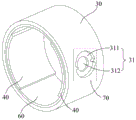
Fig. 1 is a schematic overall structure diagram of a pressure wave balloon catheter provided in an embodiment of the present application, fig. 2 is a schematic structural diagram of a catheter in the pressure wave balloon catheter provided in the embodiment of the present application, which is located inside a balloon, fig. 3 is a front view of fig. 2, and fig. 4 is a cross-sectional view taken along a line a-a in fig. 3.
Specifically, referring to fig. 1 to 4, embodiments of the present application provide a pressure wave balloon catheter, characterized by including: catheter 10, balloon 20, first conductor 30, second conductor 40, and guidewire 50;
optionally, in the embodiment of the present application, a guide wire may be disposed in the catheter 10, and the guide wire mainly functions to guide the front end of the pressure wave balloon catheter into the vascular tissue and guide the front end along the blood vessel to a lesion position (e.g., a calcified lesion), so as to perform targeted therapy on the lesion in the vascular tissue.
In some possible approaches, a guide wire may be disposed within the catheter 10. For example, the catheter 10 may be configured to be hollow so that a guide wire may be passed through the catheter 10.
In other possible examples, a lumen structure may also be provided at the forward end of the catheter 10, the lumen structure being used to guide a guidewire. For example, when the catheter 10 is a solid structure.
It is understood that the balloon 20 is disposed at the front end of the catheter 10 because the balloon 20 is to be advanced into the vascular tissue along with the front end of the catheter 10, and the balloon 20 forms a closed space with the peripheral wall of the catheter 10. The closed space is connected with the filling opening of the catheter seat, and a conductive liquid is injected into the balloon from the filling opening and expands the balloon, wherein the conductive liquid can be normal saline or a mixture of the normal saline and a contrast agent.
Referring to fig. 2, 3 and 4, the catheter 10 is recessed inwardly on the circumferential wall inside the balloon 20 to form a mounting groove 11. The installation groove 11 may be formed together with the guide tube 10 when the guide tube 10 is formed. For example, in the molding, the molding is performed by a mold. It is understood that the mounting groove 11 may be formed by a secondary process after the duct 10 is formed.
The first conductor 30 and the second conductor 40 are connected in series on the pulse circuit through a lead 50, the first conductor 30 is coated on the bottom wall of the mounting groove 11, and the second conductor 40 is positioned at one side of the first conductor 30.
In some possible ways, the circumferential wall of the conduit 10 may not be provided with the mounting groove 11, in which case the first conductor 30 is coated on the circumferential wall of the conduit 10, the second conductor 40 is located inside the first conductor 30 or the second conductor 40 is arranged on the circumferential wall of the conduit 10 alongside the first conductor 30.
Specifically, in the embodiment of the present application, the first conductor 30 and the second conductor 40 may be made of a metal material such as stainless steel, copper, silver, or tungsten. The first conductor 30 is an annular structure, and the second conductor 40 may be a metal piece with a sheet structure or the second conductor 40 may also be a wire.
Note that, since the first conductor 30 and the second conductor 40 are connected in series in the pulse circuit, the pulse circuit may be a circuit connected between the positive and negative electrodes of the pulse power source 80. Therefore, in the embodiment of the present application, a communication channel 31 is opened between the first conductor 30 and the second conductor 40, and the communication channel 31 is used for communicating the first conductor 30 and the second conductor 40 and forming the electrode 70; the electrodes 70 are used to generate pressure waves within the balloon 20 at a pulsed voltage.
Specifically, in the embodiment of the present application, the pulse power supply 80 may be a single positive pulse power supply, or may be a double positive and negative pulse power supply. Wherein, the positive pulse opening time width (positive pulse width) and the negative pulse opening time width (negative pulse width) of the positive pulse power supply and the negative pulse power supply can be respectively adjusted in the whole period.
It will be appreciated that the pulsed power supply in the embodiments of the present application may be pulsed in the form of square wave pulses, also referred to as monopulses. The single pulse power supply generally outputs a unidirectional pulse current with fixed parameters.
Of course, the pulse power supply may also be a double pulse power supply or a multi-pulse power supply in some possible ways.
Optionally, in the embodiment of the present application, the pulse power supply 80 may provide a pulse voltage of 500 to 5000V, and the pulse width may be 0.1 to 5 μ s.
Optionally, in the embodiment of the present application, a catheter hub is further disposed at the rear end of the catheter 10, and the rear end of the catheter 10 is connected to the pulse power source 80 through the catheter hub and a wire.
Thus, under the pulse voltage provided by the pulse power source 80, the first conductor 30 and the second conductor 40 generate an arc discharge phenomenon, i.e., a breakdown phenomenon, through the opened communication channel 31, so that the first conductor 30 and the second conductor 40 are conducted, and a pressure wave or a shock wave is generated in the balloon 20, thereby performing a therapeutic treatment on a lesion in the vascular tissue through the balloon 20.
In the embodiment of the present application, the first conductor 30 and the second conductor 40 are each embedded in the mounting groove 11 by forming the mounting groove 11 in the peripheral wall of the guide tube 10, the second conductor 40 is disposed on one side of the first conductor 30, and the electrode 70 is formed between the first conductor 30 and the second conductor 40 through the communication passage 31 by forming the communication passage 31 between the first conductor 30 and the second conductor 40. Therefore, the stacking of the electrode 70, the first conductor 30 and the second conductor 40 on the peripheral wall of the catheter 10 is effectively reduced, the section size of the catheter 10 can be reduced, and the passing performance of the balloon catheter in the vascular tissue can be effectively improved.
It will be appreciated that because the nature of the electrode 70 is equivalent to a capacitor, that is, in the loop of the pulse circuit, the electrode 70 will open the circuit so that the electrode 70 will only be able to arc at the pulse voltage provided by the pulse power source 80, thereby generating a pressure or shock wave within the balloon 20. To avoid the electrode 70 being directly conducted, in the embodiment of the present application, an insulating layer 60 may be disposed between the first conductor 30 and the second conductor 40; referring to fig. 3-7, fig. 5 is a schematic view showing an assembly structure of a first conductor, a second conductor and an insulating layer in the embodiment of the present application, fig. 6 is a front view of fig. 5, and fig. 7 is a schematic view showing another assembly structure of the first conductor, the second conductor and the insulating layer in the embodiment of the present application. In the embodiment of the present application, the second conductor 40 is located inside the first conductor 30, the insulating layer 60 is provided between the first conductor 30 and the second conductor 40, and the communication passage 31 penetrates the insulating layer 60 from the peripheral wall of the first conductor 30 inward.
In the embodiment of the present application, the material of the insulating layer 60 may be one or more of polyamide, polyimide, polyether block polyamide, and the like.
The communication channel 31 includes a first hole section 311 and a second hole section 312, the first hole section 311 penetrates the first conductor 30, the second hole section 312 penetrates the insulating layer 60, and the hole diameter of the first hole section 311 is larger than that of the second hole section 312.
That is, in the embodiment of the present application, the apertures of the first hole section 311 and the second hole section 312 are set to be different, so that the first conductor 30 and the second conductor 40 have a sufficient gap therebetween without direct conduction. In this way, an effective arc discharge can be ensured between the first conductor 30 and the second conductor 40.
Optionally, the aperture of the first hole section 311 is 0.25-0.6 mm, and the aperture of the second hole section 312 is 0.1-0.4 mm.
Therefore, the aperture difference between the first hole section 311 and the second hole section 312 is only 0.15-0.5 mm, namely the radius difference is only 0.075-0.25 mm, and thus, a gap is formed between the first conductor 30 and the second conductor 40, and direct conduction cannot be achieved; further, the gap is small, so that the breakdown voltage required for the electrode 70 formed of the first conductor 30 and the second conductor 40 can be effectively reduced, and the electrode loss can be reduced.
Alternatively, as shown in fig. 5 to 7, in the embodiment of the present application, the first hole segment 311 may be a special-shaped hole. The cross-section of the first hole section 311 may be other than circular, for example, elliptical, polygonal, or racetrack.
In some possible ways, radial protrusions, such as the flat protrusions shown in fig. 5-7, or sharp protrusions, may be provided on the walls of the circular hole. It will be appreciated that when the projections are sharp projections, the included angle of the projections may be 30 °, 45 °, 90 ° or 150 °; of course, any angle between 0 to 180 ° is also possible.
Alternatively, the protrusion may be disposed at one end of the cross-sectional diameter of the first bore section 311, i.e., only one protrusion may be disposed within the first bore section 311. It is understood that the convex portions may be disposed at both ends of the cross-sectional diameter of the first bore section 311, i.e., two convex portions are disposed symmetrically with respect to each other.
In this way, a tip discharge can be formed between the first conductor 30 and the second conductor 40, and the arc discharge intensity of the electrode 70 can be increased.
In one possible example, referring to fig. 8 and 9, fig. 8 is a first cross-sectional view of a balloon and a catheter in a pressure wave balloon catheter provided by an embodiment of the application, and fig. 9 is a cross-sectional view along line B-B in fig. 8. In the embodiment of the present application, the second conductor 40 includes at least two wires embedded in the conduit 10, and the front ends of the two wires are respectively communicated with the first conductor 30 through the communication channel 31.
Specifically, the conduit 10 is a solid structure or a hollow structure, and the insulating layer 60 includes the conduit 10 between the first conductor 30 and the second conductor 40.
In some possible ways, the second conductor 40 may be buried inside the catheter 10. At this point, the insulating layer 60 may be part of the conduit between the first conductor 30 and the second conductor 40.
Taking fig. 8 as an example for explanation, in a specific implementation, the rear end of one of the wires may be connected to the positive pole of the pulse power supply, and the rear end of the other wire may be connected to the negative pole of the pulse power supply. Since the leading ends of the two wires are embedded in the duct 10, the leading ends of the two wires are insulated and disconnected from each other. Then, the first conductor 30 is coated on the peripheral wall of the catheter 10, and a communication channel 31 is opened inwards from the peripheral wall of the first conductor 30, and the communication channel 31 penetrates to the position of the lead.
Thus, the communicating channel 31 is filled with the conductive liquid stored in the balloon 20, so that when the pulse power source 80 emits a pulse voltage, the positive current passes through one of the conducting wires, and an arc discharge occurs at the communicating channel 31 and the first conductor 30 (i.e., the electrode 70 is broken down), so that a pressure wave is formed; further, the current is arc-discharged on the first conductor 30 through another communication path 31 with the wire connected to the negative electrode, and flows into the negative electrode of the pulse voltage. Thereby forming a loop of the entire pulse circuit.
It will be appreciated that, with continued reference to fig. 8 and 9, a plurality of first conductors 30 may be disposed axially of the catheter 10, with the plurality of first conductors 30 being spaced apart. At this time, the number of wires as the second conductor 40 may be increased accordingly, for example, in the case where the first conductor 30 is two, the number of wires may be three as shown in fig. 3. One of which may be disposed between two first conductors 30 and form an electrode 70 with both first conductors 30.
Thus, a plurality of electrodes 70 can be formed in the axial direction of the catheter 10, and arc power generation, that is, pressure waves or shock waves can be generated in all of the electrodes 70 connected in series. After the pressure waves or the shock waves generated by the plurality of electrodes 70 are mutually superposed, the diffusion and propagation range of the pressure waves or the shock waves can be increased, and the treatment can be effectively carried out on the large blood vessels or the eccentric focuses.
Optionally, the thickness of the insulating layer 60 is 0.02-0.2 mm. Thus, the insulating layer 60 is not stacked in a large thickness in the radial direction of the duct 10, and the sectional size of the duct 10 can be effectively reduced.
Alternatively, referring to fig. 10 and 11, fig. 10 is a second cross-sectional view of the balloon and the catheter in the pressure wave balloon catheter provided in the embodiment of the present application, and fig. 11 is a third cross-sectional view of the balloon and the catheter in the pressure wave balloon catheter provided in the embodiment of the present application. In the embodiment of the present application, the second conductor 40 includes at least two metal sheets attached to the bottom wall of the mounting groove 11; the insulating layer 60 is a ring structure, and the insulating layer 60 is wrapped around the second conductor 40.
Specifically, each metal sheet corresponds to one communicating channel 31, one of the two metal sheets is connected to the positive electrode of the pulse power supply, and the other metal sheet is connected to the negative electrode of the pulse power supply.
In the embodiment of the present application, the second conductor 40 is formed by two metal sheets. In this way, the second conductor 40 can form an electrode 70 with the first conductor 10 on both sides of the catheter 10. That is, arc discharge can occur at both sides of the guide duct 10, thereby generating a pressure wave or a shock wave. Thus, a uniform pressure wave or shock wave can be generated around the catheter 10, and a lesion on the peripheral wall of the blood vessel can be uniformly treated.
Further, the first conductor 30 includes a plurality of first conductors 30, and the plurality of first conductors 30 are arranged at intervals along the axial direction of the catheter 10; two metal sheets are arranged on the inner side of each first conductor 30, and the metal sheets are connected in series on the pulse circuit through the plurality of first conductors 30 in sequence.
Specifically, as shown in fig. 10 and 11, when there are two first conductors 30, the current flows from the positive electrode of the pulse power supply 80, first flows through one metal piece (the second conductor 40 shown on the left side in fig. 10) at the front end of the conduit 10, the metal piece is subjected to arc discharge with the first conductor 30 at the front end of the conduit 10, the current flows through the first conductor 30, the first conductor 30 is subjected to arc discharge with the other metal piece, the metal piece is electrically connected to the metal piece (the second conductor 40 shown on the right side in fig. 10) in the other first conductor 30 through the wire 50, the current flows through the metal piece, the current is subjected to arc discharge with the first conductor 30, the first conductor 30 is subjected to arc discharge with the other metal piece, and the current flows back to the negative electrode of the pulse power supply 80. It is understood that in the embodiment of the present application, the positive and negative electrodes of the pulse power source 80 can be reversed, so that the current is conducted in the reverse direction.
It is understood that the connection manner of the metal sheet as the second conductor 40 in fig. 11 may be the same as or similar to the above-mentioned manner, and is not described in detail in this embodiment of the application. The difference from fig. 10 is that the 4 electrode holes are distributed more uniformly in the circumferential direction of the inner tube.
In this way, a uniform pressure wave or shock wave can be generated in both the axial and circumferential directions of the duct 10.
Alternatively, referring to fig. 12, fig. 12 is a fourth cross-sectional view of the balloon and catheter in the pressure wave balloon catheter provided by the embodiments of the present application.
The first conductor 30 and the second conductor 40 are arranged at intervals along the axial direction of the catheter 10 and are connected in series on the pulse circuit; the first conductor 30 has a protrusion 32 at its edge, and the second conductor 40 has a recess 41 at a position opposite to the protrusion 32, and the protrusion 32 and the recess 41 form an electrode 70.
In this way, the stacking of the second conductor 40 and the insulating layer 60 on the circumferential wall of the catheter 10 can be reduced, so that the cross-sectional size of the catheter 10 can be effectively reduced, and the passability of the balloon catheter in the vascular tissue can be improved.
It is understood that, in the embodiment of the present application, the positions of the protruding portion 32 and the recessed portion 41 may be interchanged.
It should be noted that, in the present embodiment, the insulating layer 60 may also be disposed between the first conductor 30 and the second conductor 40, and the communication channel 31 penetrates the insulating layer 60 at the protruding portion 32 and the recessed portion 41, so as to form the electrode 70 between the protruding portion 32 and the recessed portion 41.
Of course, in the present embodiment, the insulating layer 60 may not be provided between the first conductor 30 and the second conductor 40. Due to the presence of the projection 32 and the recess 41, a point discharge occurs between the first conductor 30 and the second conductor 40 through the projection 32 and the recess 41, and a discharge from other portions does not occur.
The above description is only for the specific embodiments of the present application, but the scope of the present application is not limited thereto, and any person skilled in the art can easily conceive of the changes or substitutions within the technical scope of the present application, and shall be covered by the scope of the present application. Therefore, the protection scope of the present application shall be subject to the protection scope of the claims.

Claims (10)

1. A pressure wave balloon catheter, comprising: a catheter (10), a balloon (20), a first conductor (30), a second conductor (40), and a guidewire (50);
the balloon (20) is arranged at the front end of the catheter (10), the balloon (20) and the peripheral wall of the catheter (10) form a closed space, and the balloon (20) extends to the interior of the vascular tissue under the driving of the catheter (10);
the catheter (10) is positioned on the peripheral wall inside the balloon (20) and is inwards sunken to form a mounting groove (11); the first conductor (30) and the second conductor (40) are connected in series on a pulse circuit through the lead (50), the first conductor (30) covers the bottom wall of the mounting groove (11), or the first conductor (30) covers the peripheral wall of the conduit (10), the second conductor (40) is positioned at one side of the first conductor (30), a communication channel (31) is arranged between the first conductor (30) and the second conductor (40), and the communication channel (31) is used for communicating the first conductor (30) and the second conductor (40) and forming an electrode (70); the electrodes (70) are for generating pressure waves within the balloon (20) at a pulsed voltage.
2. The pressure wave balloon catheter according to claim 1, wherein the second conductor (40) is located inside the first conductor (30), an insulating layer (60) is provided between the first conductor (30) and the second conductor (40), and the communication passage (31) penetrates the insulating layer (60) from a peripheral wall of the first conductor (30) inward;
the communication channel (31) comprises a first hole section (311) and a second hole section (312), the first hole section (311) penetrates through the first conductor (30), the second hole section (312) penetrates through the insulating layer (60), and the aperture of the first hole section (311) is larger than that of the second hole section (312).
3. The pressure wave balloon catheter according to claim 2, wherein the first bore section (311) has a bore diameter of 0.25-0.6 mm and the second bore section (312) has a bore diameter of 0.1-0.4 mm.
4. The pressure wave balloon catheter according to claim 2, wherein the second conductor (40) includes at least two wires buried in the catheter (10), leading ends of the two wires communicating with the first conductor (30) through the communication passages (31), respectively.
5. The pressure wave balloon catheter according to claim 4, wherein the catheter (10) is of a solid or hollow construction, the insulating layer (60) comprising the catheter (10) between the first conductor (30) and the second conductor (40).
6. The pressure wave balloon catheter according to claim 2, wherein the thickness of the insulating layer (60) is 0.02-0.2 mm.
7. The pressure wave balloon catheter according to claim 2, characterized in that the second conductor (40) comprises at least two metal sheets attached to the bottom wall of the mounting groove (11); the insulating layer (60) is of an annular structure, and the insulating layer (60) wraps the periphery of the second conductor (40).
8. The pressure wave balloon catheter according to claim 7, wherein each of the metal pieces corresponds to one of the communication channels (31), and one of the two metal pieces is connected to a positive pole of a pulse power supply, and the other metal piece is connected to a negative pole of the pulse power supply.
9. The pressure wave balloon catheter according to claim 7, wherein the first conductor (30) includes a plurality of the first conductors (30) arranged at intervals along an axial direction of the catheter (10); two metal sheets are arranged on the inner side of each first conductor (30), and the metal sheets are connected in series on the pulse circuit sequentially through the first conductors (30).
10. The pressure wave balloon catheter according to claim 1, wherein the first conductor (30) and the second conductor (40) are spaced apart in an axial direction of the catheter (10) and are connected in series on the pulse circuit; the edge of the first conductor (30) is provided with a convex part (32), the position of the second conductor (40) opposite to the convex part (32) is provided with a concave part (41), and the convex part (32) and the concave part (41) form the electrode (70).
CN202011488821.6A 2020-12-16 2020-12-16 Pressure wave sacculus pipe Pending CN113951972A (en)

Priority Applications (2)

Application Number Priority Date Filing Date Title
CN202011488821.6A CN113951972A (en) 2020-12-16 2020-12-16 Pressure wave sacculus pipe
PCT/CN2021/131540 WO2022127509A1 (en) 2020-12-16 2021-11-18 Pressure wave balloon catheter

Applications Claiming Priority (1)

Application Number Priority Date Filing Date Title
CN202011488821.6A CN113951972A (en) 2020-12-16 2020-12-16 Pressure wave sacculus pipe

Publications (1)

Publication Number Publication Date
CN113951972A true CN113951972A (en) 2022-01-21

Family

ID=79460087

Family Applications (1)

Application Number Title Priority Date Filing Date
CN202011488821.6A Pending CN113951972A (en) 2020-12-16 2020-12-16 Pressure wave sacculus pipe

Country Status (2)

Country Link
CN (1) CN113951972A (en)
WO (1) WO2022127509A1 (en)

Cited By (31)

* Cited by examiner, † Cited by third party
Publication number Priority date Publication date Assignee Title
CN114903558A (en) * 2022-05-19 2022-08-16 杭州天路医疗器械有限公司 Shock wave generating device for molding internal cavity
CN114983519A (en) * 2022-07-01 2022-09-02 深圳市赛禾医疗技术有限公司 Ring-shaped discharge electrode pair array and shock wave balloon catheter
CN115245373A (en) * 2022-09-26 2022-10-28 上海百心安生物技术股份有限公司 Pulse sacculus expansion pipe of even fragmentation
CN115337076A (en) * 2022-07-15 2022-11-15 深圳英美达医疗技术有限公司 Shock wave balloon catheter
US11517713B2 (en) 2019-06-26 2022-12-06 Boston Scientific Scimed, Inc. Light guide protection structures for plasma system to disrupt vascular lesions
CN115463317A (en) * 2022-08-23 2022-12-13 深圳市赛禾医疗技术有限公司 Shock wave balloon catheter
US11583339B2 (en) 2019-10-31 2023-02-21 Bolt Medical, Inc. Asymmetrical balloon for intravascular lithotripsy device and method
CN115844487A (en) * 2022-11-22 2023-03-28 上海精诚医疗器械有限公司 Shock wave balloon catheter and shock wave device
CN115944351A (en) * 2022-06-15 2023-04-11 上海百心安生物技术股份有限公司 Prevent short circuit pulse sacculus expansion pipe
US11648057B2 (en) 2021-05-10 2023-05-16 Bolt Medical, Inc. Optical analyzer assembly with safety shutdown system for intravascular lithotripsy device
CN116158807A (en) * 2023-04-26 2023-05-26 深圳英美达医疗技术有限公司 Shockwave Balloon Catheter
US11660427B2 (en) 2019-06-24 2023-05-30 Boston Scientific Scimed, Inc. Superheating system for inertial impulse generation to disrupt vascular lesions
US11672585B2 (en) 2021-01-12 2023-06-13 Bolt Medical, Inc. Balloon assembly for valvuloplasty catheter system
US11672599B2 (en) 2020-03-09 2023-06-13 Bolt Medical, Inc. Acoustic performance monitoring system and method within intravascular lithotripsy device
CN116392203A (en) * 2023-06-06 2023-07-07 上海佳沐垚医疗科技有限公司 Shock wave catheter, electrode connection structure and control system
CN116392200A (en) * 2023-04-10 2023-07-07 飞依诺科技股份有限公司 Shock wave electrode assembly, balloon catheter and medical equipment
US11707323B2 (en) 2020-04-03 2023-07-25 Bolt Medical, Inc. Electrical analyzer assembly for intravascular lithotripsy device
US11717139B2 (en) 2019-06-19 2023-08-08 Bolt Medical, Inc. Plasma creation via nonaqueous optical breakdown of laser pulse energy for breakup of vascular calcium
CN116687512A (en) * 2023-05-09 2023-09-05 凯诺威医疗科技(武汉)有限公司 Device for generating shock waves
US11806075B2 (en) 2021-06-07 2023-11-07 Bolt Medical, Inc. Active alignment system and method for laser optical coupling
US11819229B2 (en) 2019-06-19 2023-11-21 Boston Scientific Scimed, Inc. Balloon surface photoacoustic pressure wave generation to disrupt vascular lesions
US11839391B2 (en) 2021-12-14 2023-12-12 Bolt Medical, Inc. Optical emitter housing assembly for intravascular lithotripsy device
US11903642B2 (en) 2020-03-18 2024-02-20 Bolt Medical, Inc. Optical analyzer assembly and method for intravascular lithotripsy device
US12016610B2 (en) 2020-12-11 2024-06-25 Bolt Medical, Inc. Catheter system for valvuloplasty procedure
US12102384B2 (en) 2019-11-13 2024-10-01 Bolt Medical, Inc. Dynamic intravascular lithotripsy device with movable energy guide
US12207870B2 (en) 2020-06-15 2025-01-28 Boston Scientific Scimed, Inc. Spectroscopic tissue identification for balloon intravascular lithotripsy guidance
US12274497B2 (en) 2019-12-18 2025-04-15 Bolt Medical, Inc. Multiplexer for laser-driven intravascular lithotripsy device
US12274485B2 (en) 2021-01-12 2025-04-15 Bolt Medical, Inc. Balloon assembly for valvuloplasty catheter system
US12295654B2 (en) 2020-06-03 2025-05-13 Boston Scientific Scimed, Inc. System and method for maintaining balloon integrity within intravascular lithotripsy device with plasma generator
US12402946B2 (en) 2019-06-19 2025-09-02 Boston Scientific Scimed, Inc. Breakdown of laser pulse energy for breakup of vascular calcium
US12446961B2 (en) 2020-02-10 2025-10-21 Bolt Medical, Inc. System and method for pressure monitoring within a catheter system

Citations (8)

* Cited by examiner, † Cited by third party
Publication number Priority date Publication date Assignee Title
US20140005576A1 (en) * 2012-06-27 2014-01-02 Shockwave Medical, Inc. Shock wave balloon catheter with multiple shock wave sources
US20140039513A1 (en) * 2012-08-06 2014-02-06 Shockwave Medical, Inc. Low profile electrodes for an angioplasty shock wave catheter
US20140058376A1 (en) * 2012-08-24 2014-02-27 Boston Scientific Scimed, Inc. Renal nerve modulation devices with weeping rf ablation balloons
US20150039002A1 (en) * 2013-07-31 2015-02-05 Shockwave Medical, Inc. Angioplasty balloon
US20170135709A1 (en) * 2015-11-18 2017-05-18 Shockwave Medical, Inc. Shock wave electrodes
US20190365400A1 (en) * 2008-06-13 2019-12-05 Shockwave Medical, Inc. Two-stage method for treating calcified lesions within the wall of a blood vessel
CN111601560A (en) * 2017-11-17 2020-08-28 冲击波医疗公司 Low profile electrode for a shock waveguide
CN214966283U (en) * 2020-12-16 2021-12-03 深圳市赛禾医疗技术有限公司 Pressure wave sacculus pipe

Family Cites Families (2)

* Cited by examiner, † Cited by third party
Publication number Priority date Publication date Assignee Title
CN108452426A (en) * 2018-03-16 2018-08-28 上海心至医疗科技有限公司 A kind of foley's tube based on electrohydraulic effect
CN111790046B (en) * 2020-07-31 2024-09-27 深圳市赛禾医疗技术有限公司 A pressure wave balloon catheter

Patent Citations (8)

* Cited by examiner, † Cited by third party
Publication number Priority date Publication date Assignee Title
US20190365400A1 (en) * 2008-06-13 2019-12-05 Shockwave Medical, Inc. Two-stage method for treating calcified lesions within the wall of a blood vessel
US20140005576A1 (en) * 2012-06-27 2014-01-02 Shockwave Medical, Inc. Shock wave balloon catheter with multiple shock wave sources
US20140039513A1 (en) * 2012-08-06 2014-02-06 Shockwave Medical, Inc. Low profile electrodes for an angioplasty shock wave catheter
US20140058376A1 (en) * 2012-08-24 2014-02-27 Boston Scientific Scimed, Inc. Renal nerve modulation devices with weeping rf ablation balloons
US20150039002A1 (en) * 2013-07-31 2015-02-05 Shockwave Medical, Inc. Angioplasty balloon
US20170135709A1 (en) * 2015-11-18 2017-05-18 Shockwave Medical, Inc. Shock wave electrodes
CN111601560A (en) * 2017-11-17 2020-08-28 冲击波医疗公司 Low profile electrode for a shock waveguide
CN214966283U (en) * 2020-12-16 2021-12-03 深圳市赛禾医疗技术有限公司 Pressure wave sacculus pipe

Cited By (43)

* Cited by examiner, † Cited by third party
Publication number Priority date Publication date Assignee Title
US12402946B2 (en) 2019-06-19 2025-09-02 Boston Scientific Scimed, Inc. Breakdown of laser pulse energy for breakup of vascular calcium
US11717139B2 (en) 2019-06-19 2023-08-08 Bolt Medical, Inc. Plasma creation via nonaqueous optical breakdown of laser pulse energy for breakup of vascular calcium
US11819229B2 (en) 2019-06-19 2023-11-21 Boston Scientific Scimed, Inc. Balloon surface photoacoustic pressure wave generation to disrupt vascular lesions
US11660427B2 (en) 2019-06-24 2023-05-30 Boston Scientific Scimed, Inc. Superheating system for inertial impulse generation to disrupt vascular lesions
US12311124B2 (en) 2019-06-26 2025-05-27 Boston Scientific Scimed, Inc. Fortified balloon inflation fluid for plasma system to disrupt vascular lesions
US11911574B2 (en) 2019-06-26 2024-02-27 Boston Scientific Scimed, Inc. Fortified balloon inflation fluid for plasma system to disrupt vascular lesions
US12280223B2 (en) 2019-06-26 2025-04-22 Boston Scientific Scimed, Inc. Focusing element for plasma system to disrupt vascular lesions
US11517713B2 (en) 2019-06-26 2022-12-06 Boston Scientific Scimed, Inc. Light guide protection structures for plasma system to disrupt vascular lesions
US12186499B2 (en) 2019-06-26 2025-01-07 Boston Scientific Scimed, Inc. Light guide protection structures for plasma system to disrupt vascular lesions
US11583339B2 (en) 2019-10-31 2023-02-21 Bolt Medical, Inc. Asymmetrical balloon for intravascular lithotripsy device and method
US12102384B2 (en) 2019-11-13 2024-10-01 Bolt Medical, Inc. Dynamic intravascular lithotripsy device with movable energy guide
US12508076B2 (en) 2019-12-18 2025-12-30 Bolt Medical, Inc. Multiplexer for laser-driven intravascular lithotripsy device
US12274497B2 (en) 2019-12-18 2025-04-15 Bolt Medical, Inc. Multiplexer for laser-driven intravascular lithotripsy device
US12446961B2 (en) 2020-02-10 2025-10-21 Bolt Medical, Inc. System and method for pressure monitoring within a catheter system
US11672599B2 (en) 2020-03-09 2023-06-13 Bolt Medical, Inc. Acoustic performance monitoring system and method within intravascular lithotripsy device
US11903642B2 (en) 2020-03-18 2024-02-20 Bolt Medical, Inc. Optical analyzer assembly and method for intravascular lithotripsy device
US11707323B2 (en) 2020-04-03 2023-07-25 Bolt Medical, Inc. Electrical analyzer assembly for intravascular lithotripsy device
US12295654B2 (en) 2020-06-03 2025-05-13 Boston Scientific Scimed, Inc. System and method for maintaining balloon integrity within intravascular lithotripsy device with plasma generator
US12207870B2 (en) 2020-06-15 2025-01-28 Boston Scientific Scimed, Inc. Spectroscopic tissue identification for balloon intravascular lithotripsy guidance
US12016610B2 (en) 2020-12-11 2024-06-25 Bolt Medical, Inc. Catheter system for valvuloplasty procedure
US11672585B2 (en) 2021-01-12 2023-06-13 Bolt Medical, Inc. Balloon assembly for valvuloplasty catheter system
US12274485B2 (en) 2021-01-12 2025-04-15 Bolt Medical, Inc. Balloon assembly for valvuloplasty catheter system
US11648057B2 (en) 2021-05-10 2023-05-16 Bolt Medical, Inc. Optical analyzer assembly with safety shutdown system for intravascular lithotripsy device
US11806075B2 (en) 2021-06-07 2023-11-07 Bolt Medical, Inc. Active alignment system and method for laser optical coupling
US12232753B2 (en) 2021-12-14 2025-02-25 Bolt Medical, Inc. Optical emitter housing assembly for intravascular lithotripsy device
US11839391B2 (en) 2021-12-14 2023-12-12 Bolt Medical, Inc. Optical emitter housing assembly for intravascular lithotripsy device
CN114903558A (en) * 2022-05-19 2022-08-16 杭州天路医疗器械有限公司 Shock wave generating device for molding internal cavity
CN114903558B (en) * 2022-05-19 2023-11-10 杭州天路医疗器械有限公司 Shock wave generating device for molding body cavity channel
CN115944351A (en) * 2022-06-15 2023-04-11 上海百心安生物技术股份有限公司 Prevent short circuit pulse sacculus expansion pipe
CN115944351B (en) * 2022-06-15 2025-10-28 上海百心安生物技术股份有限公司 A short-circuit-proof pulse balloon dilatation catheter
CN114983519B (en) * 2022-07-01 2025-07-25 深圳市赛禾医疗技术有限公司 Annular discharge electrode pair array and shock wave balloon catheter
CN114983519A (en) * 2022-07-01 2022-09-02 深圳市赛禾医疗技术有限公司 Ring-shaped discharge electrode pair array and shock wave balloon catheter
CN115337076A (en) * 2022-07-15 2022-11-15 深圳英美达医疗技术有限公司 Shock wave balloon catheter
CN115463317B (en) * 2022-08-23 2023-08-29 深圳市赛禾医疗技术有限公司 Shock wave balloon catheter
CN115463317A (en) * 2022-08-23 2022-12-13 深圳市赛禾医疗技术有限公司 Shock wave balloon catheter
CN115245373A (en) * 2022-09-26 2022-10-28 上海百心安生物技术股份有限公司 Pulse sacculus expansion pipe of even fragmentation
CN115844487A (en) * 2022-11-22 2023-03-28 上海精诚医疗器械有限公司 Shock wave balloon catheter and shock wave device
CN116392200A (en) * 2023-04-10 2023-07-07 飞依诺科技股份有限公司 Shock wave electrode assembly, balloon catheter and medical equipment
CN116158807A (en) * 2023-04-26 2023-05-26 深圳英美达医疗技术有限公司 Shockwave Balloon Catheter
CN116687512A (en) * 2023-05-09 2023-09-05 凯诺威医疗科技(武汉)有限公司 Device for generating shock waves
WO2024250844A1 (en) * 2023-06-06 2024-12-12 上海佳沐垚医疗科技有限公司 Shockwave catheter, electrode connection structure, and control system
CN116392203B (en) * 2023-06-06 2023-09-22 上海佳沐垚医疗科技有限公司 Shock wave catheter, electrode connection structure and control system
CN116392203A (en) * 2023-06-06 2023-07-07 上海佳沐垚医疗科技有限公司 Shock wave catheter, electrode connection structure and control system

Also Published As

Publication number Publication date
WO2022127509A1 (en) 2022-06-23

Similar Documents

Publication Publication Date Title
CN113951972A (en) Pressure wave sacculus pipe
CN113951973A (en) Pressure wave sacculus pipe
CN214966283U (en) Pressure wave sacculus pipe
US12402897B2 (en) System for treating thrombus in body lumens
US12232754B2 (en) Device and method for generating forward directed shock waves
US10603058B2 (en) Unfocused electrohydraulic lithotripter
CN214907695U (en) Pressure wave sacculus pipe and medical instrument
US20110202052A1 (en) System for treating benign prostatic hyperplasia
JP2021527504A (en) A system for treating obstructions in the body lumen
US20240268843A1 (en) System for treating thrombus in body lumens
US12035932B1 (en) Intravascular lithotripsy catheter with slotted emitter bands
CN215960130U (en) Pressure wave sacculus pipe
WO2024060518A1 (en) Shock wave balloon catheter device
CN218979093U (en) Shock wave electrode assembly and balloon catheter device
US20250352228A1 (en) Systems, devices, and methods for generating shock waves in a forward direction
CN119074132A (en) A shock wave guide for penetrating high resistance lesions
WO2024130853A1 (en) Shock wave balloon catheter device
WO2022127507A1 (en) Pressure wave balloon catheter and medical device
US20250176986A1 (en) Shock wave catheter with shock absorber
CN119236276B (en) External guidewire shockwave balloon catheter
CN119055934B (en) A balloon catheter based on liquid corona discharge
JP2020025731A (en) Medical device
JP2026020342A (en) System for treating a thrombus in a body lumen
CN118267045A (en) Shock wave electrode assembly and balloon catheter device

Legal Events

Date Code Title Description
PB01 Publication
PB01 Publication
SE01 Entry into force of request for substantive examination