JP2017138099A - Nondestructive inspection apparatus - Google Patents
Nondestructive inspection apparatus Download PDFInfo
- Publication number
- JP2017138099A JP2017138099A JP2014126125A JP2014126125A JP2017138099A JP 2017138099 A JP2017138099 A JP 2017138099A JP 2014126125 A JP2014126125 A JP 2014126125A JP 2014126125 A JP2014126125 A JP 2014126125A JP 2017138099 A JP2017138099 A JP 2017138099A
- Authority
- JP
- Japan
- Prior art keywords
- pipe
- magnetic sensor
- magnetic
- axial direction
- inspected
- Prior art date
- Legal status (The legal status is an assumption and is not a legal conclusion. Google has not performed a legal analysis and makes no representation as to the accuracy of the status listed.)
- Pending
Links
Images


Classifications
-
- G—PHYSICS
- G01—MEASURING; TESTING
- G01N—INVESTIGATING OR ANALYSING MATERIALS BY DETERMINING THEIR CHEMICAL OR PHYSICAL PROPERTIES
- G01N27/00—Investigating or analysing materials by the use of electric, electrochemical, or magnetic means
- G01N27/72—Investigating or analysing materials by the use of electric, electrochemical, or magnetic means by investigating magnetic variables
- G01N27/82—Investigating or analysing materials by the use of electric, electrochemical, or magnetic means by investigating magnetic variables for investigating the presence of flaws
Landscapes
- Chemical & Material Sciences (AREA)
- Chemical Kinetics & Catalysis (AREA)
- Electrochemistry (AREA)
- Physics & Mathematics (AREA)
- Health & Medical Sciences (AREA)
- Life Sciences & Earth Sciences (AREA)
- Analytical Chemistry (AREA)
- Biochemistry (AREA)
- General Health & Medical Sciences (AREA)
- General Physics & Mathematics (AREA)
- Immunology (AREA)
- Pathology (AREA)
- Investigating Or Analyzing Materials By The Use Of Magnetic Means (AREA)
Abstract
Description
本発明は、非破壊検査装置に関する。 The present invention relates to a nondestructive inspection apparatus.
従来、鋼材の欠陥を検査する方法として、磁気を用いた渦電流探傷方法や漏洩磁束探傷方法がある。渦電流探傷方法は、測定対象に交流の磁場を印加させて、測定対象に発生する渦電流の変化をみるものである。すなわち、測定対象に交流の磁場を印加した場合、測定対象の欠陥のない部分に対して欠陥がある部分は渦電流の分布が変化するので、渦電流が作る磁場も変化することになる。この渦電流の変化をサーチコイルや、磁気抵抗素子(MR)等の磁気センサーで検出することで欠陥検査が行われている。一方、漏洩磁束探傷法は、測定対象に直流あるいは交流の磁場を印加させ、欠陥部から漏れ出る磁束をサーチコイルあるいは磁気センサーで検出するものである。 Conventionally, as a method for inspecting a defect in a steel material, there are an eddy current flaw detection method and a magnetic flux leakage flaw detection method using magnetism. In the eddy current flaw detection method, an alternating magnetic field is applied to a measurement object, and a change in eddy current generated in the measurement object is observed. That is, when an alternating magnetic field is applied to the measurement target, the distribution of eddy current changes in the portion having a defect relative to the portion having no defect in the measurement target, so the magnetic field generated by the eddy current also changes. A defect inspection is performed by detecting a change in the eddy current by a magnetic sensor such as a search coil or a magnetoresistive element (MR). On the other hand, in the leakage magnetic flux flaw detection method, a DC or AC magnetic field is applied to an object to be measured, and a magnetic flux leaking from a defective portion is detected by a search coil or a magnetic sensor.
特許文献1には、パルス磁気を用いた非破壊検査装置が記載されている。
詳しくは特許文献1には、被検査配管の欠陥を非破壊検査するパルス磁気を用いた非破壊検査装置であって、被検査配管を挿通し、当該被検査配管に対して任意の位置に配置可能な一対の励磁コイルと、当該一対の励磁コイルの少なくとも一つにパルス電圧を印加するパルス電源と、被検査配管の外周面上で、一対の励磁コイルの間に配置され、被検査配管の中心軸方向に平行な磁場を検出する磁気センサーと、一対の励磁コイルの少なくとも一つをパルス電源で駆動した際に発生するパルス磁場を磁気センサーにより検出し、当該磁気センサーにより検出したパルス磁場の応答を解析する手段と、を備えたことを特徴とするパルス磁気を用いた非破壊検査装置が開示されている。
かかる非破壊検査装置によれば、被検査配管を挿通する一対の励磁コイルにより被検査配管の所定の場所に被検査配管の中心軸方向の磁場を印加することができる。また、被検査配管の外周面上において、一対の励磁コイルの間に配置した磁気センサーを備えることより、被検査配管中心軸方向に平行な磁場を検出することができる。励磁コイルによって発生した磁場は被検査配管を伝わって磁気センサーのところまで伝わっていく。その途中では被検査配管の中心軸方向の磁場が外部に漏れるが、腐食や欠陥によって伝搬される磁場が異なってくる。ここで、励磁コイルをパルス電源で駆動し発生する磁場をパルス磁場とすることにより、パルス磁場の立ち上がり時およびその後一定磁場を印加している時間帯で、磁気センサーで検出した立ち上がり磁気信号が時間とともに減衰する。この検出したパルス磁気信号のピーク値や減衰特性を解析することにより配管の腐食や亀裂等の欠陥をより精度よく検知することができる。
Specifically,
According to such a nondestructive inspection apparatus, a magnetic field in the direction of the central axis of the pipe to be inspected can be applied to a predetermined location of the pipe to be inspected by a pair of exciting coils inserted through the pipe to be inspected. Further, by providing a magnetic sensor arranged between the pair of exciting coils on the outer peripheral surface of the pipe to be inspected, a magnetic field parallel to the central axis direction of the pipe to be inspected can be detected. The magnetic field generated by the exciting coil travels through the pipe to be inspected to the magnetic sensor. In the middle, the magnetic field in the direction of the central axis of the pipe to be inspected leaks to the outside, but the magnetic field propagated by corrosion and defects differs. Here, when the excitation coil is driven by a pulse power source and the generated magnetic field is a pulsed magnetic field, the rising magnetic signal detected by the magnetic sensor is timed at the time of rising of the pulsed magnetic field and the time zone during which a constant magnetic field is applied thereafter. Attenuates with. By analyzing the peak value and attenuation characteristics of the detected pulse magnetic signal, it is possible to detect defects such as corrosion and cracks in the pipe with higher accuracy.
また特許文献1の段落0046には、一対の励磁コイルのから等距離の中央部に複数の磁気センサーを円周方向に配置し、この磁気センサーの個数が多いほど空間分解能を向上させることができることが述べられるとともに、さらに励磁コイル及び磁気センサーを搭載した検査部を被検査配管が挿入された状態で動かして多点計測することにより面データを得てマッピングができることが述べられる。
Further, in paragraph 0046 of
しかしながら、以上の従来技術にあっては次のような課題がある。
特許文献1に記載の複数の磁気センサーを円周方向に配置する構成にあっては、一対の励磁コイルから等距離の中央部に複数の磁気センサーを円周方向に配置するから、円周方向の磁気センサーの列は一列でしかない。
ところで、検査対象はプラント等に配置される配管が対象となり、現場での検査が求められる。
その場合、地磁気や、地震などによる検査地の自然環境に起因した磁気はもちろん、電磁気利用の装置などの人工物から発生する磁気がノイズとなり、配管を通した微弱な検査用のパルス磁気信号を精度よく検出することが困難となり得る。
このようなノイズ環境下において磁気センサーの検出信号の信頼性を向上するために、磁気センサーで同一点を複数回に亘って検査用のパルス磁気信号を検出することが考えられる。しかし、特許文献1に記載の発明では、励磁コイル及び磁気センサーを搭載した検査部を被検査配管が挿入された状態で動かして多点計測する際に、同一点での停止時間が必要となるから、被検査配管の軸方向に一定の距離を移動するのに長時間を要してしまい、検査時間が増大する。
また、特許文献1に記載の発明にあっては、同文献で述べられるように円周方向に配置する磁気センサーの個数を増やせば空間分解能が向上するが、円周方向に並んだ磁気センサーのピッチが空間分解能を決定するので、それ以上に分解能を向上することができず、磁気センサー間の隙間をゼロにしても、円周方向に沿った磁気センサーの寸法より細かな分解能は達成できないこととなる。その反面、磁気センサー間の隙間を開けることで、磁気センサーの駆動配線、駆動回路を減らすことができる。
However, the above prior art has the following problems.
In the configuration in which the plurality of magnetic sensors described in
By the way, the inspection object is piping arranged in a plant or the like, and inspection on site is required.
In that case, not only the magnetism caused by the natural environment of the inspection site due to geomagnetism or earthquakes, but also the magnetism generated from an artificial object such as an electromagnetic device becomes noise, and a weak pulse magnetic signal for inspection through the pipe is generated. It can be difficult to detect accurately.
In order to improve the reliability of the detection signal of the magnetic sensor in such a noise environment, it is conceivable to detect a pulse magnetic signal for inspection at the same point multiple times with the magnetic sensor. However, in the invention described in
Further, in the invention described in
本発明は以上の従来技術における問題に鑑みてなされたものであって、励磁コイルと複数の磁気センサーが用いられ、配管の欠陥を探知する非破壊検査装置において、検査の信頼性又は空間分解能を向上することを課題とする。 The present invention has been made in view of the problems in the prior art described above. In the nondestructive inspection apparatus that uses an exciting coil and a plurality of magnetic sensors to detect a defect in piping, the reliability of inspection or spatial resolution is improved. The challenge is to improve.
以上の課題を解決するための請求項1記載の発明は、被検査配管の欠陥を非破壊検査する磁気を用いた非破壊検査装置であって、
励磁コイル及び磁気センサーを搭載し、前記被検査配管の外側に配置され前記被検査配管の軸方向に移動する可動検査部と、
前記可動検査部の移動速度、前記励磁コイルに印加する電圧及び前記磁気センサーを制御する制御手段と、を備え、
前記励磁コイルは、前記被検査配管が挿通され、前記軸方向に互いに離れて配置される対で構成され、
前記磁気センサーは、前記軸方向に互いに離れた前記励磁コイルの間で、前記被検査配管の円周方向に1又は複数配置され、少なくとも前記軸方向に所定距離を隔てた位置に配置される複数で構成され、
前記制御手段は、前記電圧の周期又はその2以上の整数倍と前記可動検査部が前記所定距離分だけ移動するのに要する時間とが相等しくなるように制御することを特徴とする非破壊検査装置である。
Invention of
A movable inspection unit that is equipped with an excitation coil and a magnetic sensor and is arranged outside the inspection pipe and moves in the axial direction of the inspection pipe;
A moving speed of the movable inspection unit, a voltage applied to the excitation coil and a control means for controlling the magnetic sensor,
The exciting coil is constituted by a pair in which the pipe to be inspected is inserted and arranged apart from each other in the axial direction,
One or a plurality of the magnetic sensors are arranged in the circumferential direction of the pipe to be inspected between the excitation coils that are separated from each other in the axial direction, and a plurality of magnetic sensors are arranged at least at a predetermined distance in the axial direction. Consists of
The control means controls the non-destructive inspection so that a period of the voltage or an integral multiple of 2 or more thereof is equal to a time required for the movable inspection unit to move by the predetermined distance. Device.
請求項2記載の発明は、前記所定距離を隔てた位置に配置される複数の磁気センサーの間の区間に、1又は2以上の磁気センサーが配置され、当該間の区間に配置される磁気センサーから前記軸方向に同所定距離を隔てた位置に別の磁気センサーが配置される請求項1に記載の非破壊検査装置である。
According to a second aspect of the present invention, one or two or more magnetic sensors are arranged in a section between a plurality of magnetic sensors arranged at a position separated by the predetermined distance, and the magnetic sensor is arranged in the section between the two. The nondestructive inspection apparatus according to
請求項3記載の発明は、前記磁気センサーにより検出した信号を解析する解析手段を備え、
前記解析手段は、被検査配管上のある位置に異なるタイミングで配置された前記所定距離を隔てた位置に配置される複数の磁気センサーにより検出した信号の組に基づき、同位置を測定点とした前記欠陥に起因した信号を解析することを特徴とする請求項1又は請求項2に記載の非破壊検査装置である。
The invention according to claim 3 comprises analysis means for analyzing the signal detected by the magnetic sensor,
The analysis means uses the same position as a measurement point based on a set of signals detected by a plurality of magnetic sensors arranged at different positions arranged at different timings at a certain position on the pipe to be inspected. 3. The nondestructive inspection apparatus according to
請求項4記載の発明は、前記解析手段は、前記組に含まれる信号の波形同士が、ノイズが無ければ相似形であるとの仮定に基づき、当該ノイズを検出することを特徴とする請求項3に記載の非破壊検査装置である。 The invention according to claim 4 is characterized in that the analysis means detects the noise based on the assumption that the waveforms of the signals included in the set are similar if there is no noise. 3 is a nondestructive inspection apparatus.
請求項5記載の発明は、被検査配管の欠陥を非破壊検査する磁気を用いた非破壊検査装置であって、
励磁コイル及び磁気センサーを搭載し、前記被検査配管の外側に配置され前記被検査配管の軸方向に移動する可動検査部と、
前記可動検査部の移動速度、前記励磁コイルに印加する電圧及び前記磁気センサーを制御する制御手段と、を備え、
前記励磁コイルは、前記被検査配管が挿通され、前記軸方向に互いに離れて配置される対で構成され、
前記磁気センサーは、前記軸方向に互いに離れた前記励磁コイルの間で、前記被検査配管の円周方向に並べられる複数で円周方向の列を構成し、かつ、当該円周方向の列を2列以上構成し、当該列に属する各磁気センサーは、隣接する他の列に属する磁気センサーに対して前記円周方向にオフセット配置されていることを特徴とする非破壊検査装置である。
The invention according to
A movable inspection unit that is equipped with an excitation coil and a magnetic sensor and is arranged outside the inspection pipe and moves in the axial direction of the inspection pipe;
A moving speed of the movable inspection unit, a voltage applied to the excitation coil and a control means for controlling the magnetic sensor,
The exciting coil is constituted by a pair in which the pipe to be inspected is inserted and arranged apart from each other in the axial direction,
The magnetic sensor comprises a plurality of circumferential rows arranged in the circumferential direction of the pipe to be inspected between the excitation coils separated from each other in the axial direction, and the circumferential rows are arranged in the circumferential direction. The non-destructive inspection apparatus is configured to include two or more rows, and each magnetic sensor belonging to the row is offset in the circumferential direction with respect to the magnetic sensors belonging to other adjacent rows.
請求項6記載の発明は、被検査配管の欠陥を非破壊検査する磁気を用いた非破壊検査装置であって、
励磁コイル及び磁気センサーを搭載し、前記被検査配管の外側に配置され前記被検査配管の軸方向に移動する可動検査部と、
前記可動検査部の移動速度、前記励磁コイルに印加する電圧及び前記磁気センサーを制御する制御手段と、を備え、
前記励磁コイルは、前記被検査配管が挿通され、前記軸方向に互いに離れて配置される対で構成され、
前記磁気センサーは、前記軸方向に互いに離れた前記励磁コイルの間で、前記被検査配管の円周方向及び/又は軸方向に並べられる複数で構成され、
当該複数の磁気センサーには、前記被検査配管の中心軸に平行な方向の磁場を検出する磁気センサーと、前記中心軸に対しねじれ角を有する方向の磁場を検出する磁気センサー及び/又は前記中心軸と交わる直線に平行な方向の磁場を検出する磁気センサーとが含まれていることを特徴とする非破壊検査装置である。
The invention according to claim 6 is a nondestructive inspection device using magnetism for nondestructive inspection of a defect of a pipe to be inspected,
A movable inspection unit that is equipped with an excitation coil and a magnetic sensor and is arranged outside the inspection pipe and moves in the axial direction of the inspection pipe;
A moving speed of the movable inspection unit, a voltage applied to the excitation coil and a control means for controlling the magnetic sensor,
The exciting coil is constituted by a pair in which the pipe to be inspected is inserted and arranged apart from each other in the axial direction,
The magnetic sensor is composed of a plurality arranged in the circumferential direction and / or the axial direction of the pipe to be inspected between the exciting coils separated from each other in the axial direction.
The plurality of magnetic sensors include a magnetic sensor that detects a magnetic field in a direction parallel to a central axis of the pipe to be inspected, a magnetic sensor that detects a magnetic field in a direction having a twist angle with respect to the central axis, and / or the center. A non-destructive inspection apparatus including a magnetic sensor for detecting a magnetic field in a direction parallel to a straight line intersecting with an axis.
請求項7記載の発明は、前記被検査配管の中心軸に平行な方向の磁場を検出する磁気センサーと、前記中心軸に対しねじれ角を有する方向の磁場を検出する磁気センサー及び/又は前記中心軸と交わる直線と平行な方向の磁場を検出する磁気センサーとが、前記円周方向又は前記軸方向に交互に並べられていることを特徴とする請求項6に記載の非破壊検査装置である。
The invention according to
請求項8記載の発明は、被検査配管の欠陥を非破壊検査する磁気を用いた非破壊検査装置であって、
励磁コイル及び磁気センサーを搭載し、前記被検査配管の外側に配置され前記被検査配管の軸方向に移動する可動検査部と、
前記可動検査部の移動速度、前記励磁コイルに印加する電圧及び前記磁気センサーを制御する制御手段と、を備え、
前記励磁コイルは、前記被検査配管が挿通され、前記軸方向に互いに離れて配置される対で構成され、
前記磁気センサーは、前記軸方向に互いに離れた前記励磁コイルの間で、前記被検査配管の円周方向に1又は複数配置され、少なくとも前記軸方向に所定距離を隔てた位置に配置される複数で構成され、当該所定距離が変更可能に可動支持されていることを特徴とする非破壊検査装置である。
The invention according to claim 8 is a nondestructive inspection apparatus using magnetism for nondestructive inspection of a defect of a pipe to be inspected,
A movable inspection unit that is equipped with an excitation coil and a magnetic sensor and is arranged outside the inspection pipe and moves in the axial direction of the inspection pipe;
A moving speed of the movable inspection unit, a voltage applied to the excitation coil and a control means for controlling the magnetic sensor,
The exciting coil is constituted by a pair in which the pipe to be inspected is inserted and arranged apart from each other in the axial direction,
One or a plurality of the magnetic sensors are arranged in the circumferential direction of the pipe to be inspected between the excitation coils that are separated from each other in the axial direction, and a plurality of magnetic sensors are arranged at least at a predetermined distance in the axial direction. The nondestructive inspection apparatus is characterized in that the predetermined distance is movably supported so as to be changeable.
請求項9記載の発明は、被検査配管の欠陥を非破壊検査する磁気を用いた非破壊検査装置であって、
励磁コイル及び磁気センサーを搭載し、前記被検査配管の外側に配置され前記被検査配管の軸方向に移動する可動検査部と、
前記可動検査部の移動速度、前記励磁コイルに印加する電圧及び前記磁気センサーを制御する制御手段と、を備え、
前記励磁コイルは、前記被検査配管が挿通され、前記軸方向に互いに離れて配置される対で構成され、
前記磁気センサーは、前記軸方向に互いに離れた前記励磁コイルの間で、前記被検査配管の円周方向に1又は複数配置され、少なくとも前記軸方向に並べられて配置され、
前記制御手段は、前記軸方向に並べられた磁気センサーの中から選択して前記欠陥を探知するための磁場の検出に使用することを特徴とする非破壊検査装置である。
The invention according to
A movable inspection unit that is equipped with an excitation coil and a magnetic sensor and is arranged outside the inspection pipe and moves in the axial direction of the inspection pipe;
A moving speed of the movable inspection unit, a voltage applied to the excitation coil and a control means for controlling the magnetic sensor,
The exciting coil is constituted by a pair in which the pipe to be inspected is inserted and arranged apart from each other in the axial direction,
One or a plurality of the magnetic sensors are arranged in the circumferential direction of the pipe to be inspected between the excitation coils separated from each other in the axial direction, and arranged at least in the axial direction,
The control means is a non-destructive inspection apparatus that is used for detecting a magnetic field for detecting the defect by selecting from the magnetic sensors arranged in the axial direction.
本件請求項1から請求項4のうちいずれか一に係る発明によれば、励磁コイル及び磁気センサーを搭載した可動検査部を移動させることで、異なる磁気センサーを被検査配管上の同位置に順次配置して磁場の検出を実行し、これにより得られた同一箇所に対する複数の検出信号に基づき解析することですることで検査の信頼性を向上することができる。
According to the invention according to any one of
本件請求項5に係る発明によれば、磁気センサーが配置された位置に加え、磁気センサーが配置されていない位置での検出信号をその周囲の磁気センサーの検出信号に基づき補間することができ、空間分解能を向上することができる。
According to the invention of
本件請求項6又は請求項7に係る発明によれば、被検査配管の欠陥に起因した信号は、被検査配管の中心軸に平行な方向の磁場を検出する磁気センサーによって検出可能であるとともに、外乱磁場はこの方向に限らないため、同中心軸に対しねじれ角を有する方向の磁場を検出する磁気センサー及び/又は同中心軸と交わる直線に平行な方向の磁場を検出する磁気センサーによって検出することができ、外乱磁場を弁別して検査の信頼性を向上することができる。
According to the present invention according to claim 6 or
本件請求項8に係る発明によれば、被検査配管の軸方向についての磁気センサーの配置間隔を変更することで、本件請求項1から請求項4のうちいずれか一に係る発明のように移動速度の変更に対応することができたり、空間分解能を変更することができたりするほか、励磁コイル間の任意の位置に磁気センサーを配置して磁場を検出することができる。
According to the invention according to claim 8 of the present invention, the magnetic sensor is moved as in the invention according to any one of
本件請求項9に係る発明によれば、被検査配管の軸方向に並べられた磁気センサーの中から選択して欠陥を探知するための磁場の検出に使用するので、本件請求項1から請求項4のうちいずれか一に係る発明のように移動速度の変更に対応して使用する磁気センサー間の間隔を変更することができたり、空間分解能を変更することができたりするほか、励磁コイル間の任意の位置の磁気センサーを選択して磁場を検出することができる。
According to the invention according to
以下に本発明の一実施形態につき図面を参照して説明する。以下は本発明の一実施形態であって本発明を限定するものではない。 An embodiment of the present invention will be described below with reference to the drawings. The following is one embodiment of the present invention and does not limit the present invention.
〔第1実施形態〕
まず、第1実施形態につき説明する。
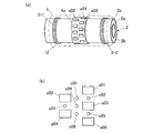
図1は、本発明の第1実施形態であるパルス磁気を用いた非破壊検査装置1(以下、パルス磁気検査装置1という)の基本構成を示す概略図である。
パルス磁気検査装置1は、断熱配管2にパルス磁場を印加して、断熱配管2に流れるパルス磁場の変化を検出することにより断熱配管2の欠陥を探傷する非破壊検査装置であり、一対の励磁コイル3−1、3−2と、環状の磁気センサーユニット4a、4bと、円筒状の自走型移動体5と、走行用駆動回路6と、磁気センサー用回路7と、パルス電源8と、電源切り替え回路9と、制御手段及び解析手段として機能するコンピューター10と、を備えて構成される。
[First Embodiment]
First, the first embodiment will be described.
FIG. 1 is a schematic diagram showing a basic configuration of a
The pulse
自走型移動体5に、励磁コイル3−1、3−2と、磁気センサーユニット4a、4bと、走行用駆動回路6と、磁気センサー用回路7と、パルス電源8と、電源切り替え回路9と、コンピューター10とが搭載されて、可動検査部12が構成される。すなわち、可動検査部12は断熱配管2の外側に配置され断熱配管2の軸方向に移動するものである。以下、断熱配管2の軸方向を単に「軸方向」と、断熱配管2の円周方向を単に「円周方向」という。
図示しないが可動検査部12を移動させるために、自走型移動体5には走行用駆動回路6によって駆動されるモーター、断熱配管2の外面に接触して可動検査部12の全体を支持する複数の走行用車輪等を備え、そのモーターの回転力で走行用車輪の全部又は適当な一部を回転駆動させて、断熱配管2に沿って走行するように構成されている。
コンピューター10から走行用駆動回路6に入力される制御信号に従って、軸方向に沿った可動検査部12の位置及び移動速度が制御される。これにより、断熱配管2に対する励磁コイル3−1、3−2及び磁気センサーの位置及び移動速度が制御されることになる。
The self-propelled moving
Although not shown, in order to move the
In accordance with a control signal input from the
励磁コイル3−1、3−2は、断熱配管2が挿通され、軸方向に互いに離れて配置される対で構成されており、可動検査部12の移動に伴って断熱配管2に対して任意の位置に配置可能である。
The exciting coils 3-1 and 3-2 are configured by pairs in which the
磁気センサーユニット4a、4bのそれぞれは、環状に構成され、断熱配管2が挿通される。
磁気センサーユニット4aには、複数の磁気センサーa(a01,a02,・・・a09・・・)が円周方向に並んで配置されている。なお、磁気センサーユニット4a上の個々の磁気センサーを特定するために符号a01,a02,・・・を用い、個々を特定しない場合は「磁気センサーa」という。
同様に磁気センサーユニット4bには、複数の磁気センサーb(b01,b02,・・・b09・・・)が円周方向に並んで配置されている。同様に磁気センサーユニット4b上の個々の磁気センサーを特定するために符号b01,b02,・・・を用い、個々を特定しない場合は「磁気センサーb」という。
磁気センサーa,bは、断熱配管2の外周面上で、一対の励磁コイル3−1、3−2の間に配置され、断熱配管2の中心軸に平行な方向の磁場を検出する。
磁気センサーユニット4a、4bが互いに軸方向に所定距離を隔てた位置に配置されることで、磁気センサーaと磁気センサーbとが軸方向に所定距離PAを隔てた位置に配置される。
Each of the
In the
Similarly, in the
The magnetic sensors a and b are disposed between the pair of exciting coils 3-1 and 3-2 on the outer peripheral surface of the
The
断熱配管2は、本実施形態に係るパルス磁気検査装置1により検査される円筒形の被検査材であって、断熱配管2の内部には厚さ7.2mmの鋼管2aを有する。この鋼管2aの周囲は、厚さ50mmの断熱材2bで覆われており、当該断熱材2bの周囲は外筒2cとして厚さ0.3mmの溶融亜鉛鉄板で覆われている。なお、数値は一例である。
The
可動検査部12は、断熱配管2を挿入させ励磁コイル3−1、3−2を介してパルス磁場を印加するとともに、断熱配管2を伝わっていく磁場の変化を磁気抵抗素子からなる磁気センサーa,bで検出する。ここで、磁気センサーa,bとしては磁気抵抗素子(MR素子)のほか、磁気インピーダンス素子、ホール素子、フラックス・ゲート、超伝導量子干渉素子(SQUID)等の極低周波からの磁気信号を計測できる磁気センサーを使うことができる。
The
磁気センサー用回路7は、磁気センサーa,bを駆動し、磁場を計測するための回路である。磁気センサーa,bが実装され、磁気センサーユニット4a、4bに設けられたフレキシブル配線基板を介して磁気センサー用回路7が磁気センサーa,bに電気的に接続される。
The
パルス電源8は、一対の励磁コイル3−1、3−2の少なくとも一つにパルス電圧を印加することができる。パルス電源8は、方形波を出力することができ、所定の繰り返し周波数及びデューティ比で駆動することができる。パルス電源8は、電源切り替え回路9に電気的に接続されている。
The pulse power supply 8 can apply a pulse voltage to at least one of the pair of exciting coils 3-1 and 3-2. The pulse power supply 8 can output a square wave and can be driven at a predetermined repetition rate and duty ratio. The pulse power supply 8 is electrically connected to the power
電源切り替え回路9は、一対の励磁コイルの一方の励磁コイルと他方の励磁コイルの電流の方向をそれぞれ同じ方向あるいは反対方向に切り替え、あるいは前記一対の励磁コイルの片方だけ駆動するように切り替え可能な回路である。電源切り替え回路9により、一対の励磁コイル3−1および3−2に流れる電流の方向と、両方あるいはどちらか片方だけを動作させることを選択することができる。ここで、両方の励磁コイル3−1および3−2の電流方向を同じにして動作させると、断熱配管2へは同じ方向のパルス磁場を印加することができる。
The power
コンピューター10は、一対の励磁コイル3−1、3−2の少なくとも一つをパルス電源8で駆動した際に発生するパルス磁場を磁気センサーa,bにより検出し、当該磁気センサーa,bにより検出したパルス磁場の応答を解析する解析手段として機能する。
なお、コンピューター10に入力された検出信号波形のデータを、無線通信やデータ記録媒体の移動によって他のコンピューター11に入力し、パルス磁場応答の解析を当該コンピューター11により実施してもよい。すなわち、当該解析手段をコンピューター11に構成することができ、必ずしも可動検査部12に解析手段を搭載する必要はない。
また、コンピューター10は、可動検査部12の移動速度、励磁コイル3−1、3−2に印加する電圧及び磁気センサーa,bを制御する制御手段として機能する。
The
The detection signal waveform data input to the
The
パルス磁気検査装置1を用いて、断熱配管2を検査する方法は、特許文献1に記載の方法を基本とする。
すなわち、パルス磁気検査装置1に適用する検査方法は、断熱配管2の欠陥を非破壊検査する方法であって、一対の励磁コイル3−1、3−2に断熱配管2を挿通し、パルス電源8により一対の励磁コイル3−1、3−2を駆動することで、断熱配管2に対してパルス磁場を印加する工程と、一対の励磁コイル3−1、3−2により発生した断熱配管2の中心軸方向に平行な磁場を磁気センサーa,bにより検出する工程と、磁気センサーa,bの出力信号におけるパルス強度および信号時間減衰を解析することで断熱配管2の欠陥を特定する工程と、を実施する。
The method of inspecting the
That is, the inspection method applied to the pulse
さらに本実施形態では、パルス磁気検査装置1によって以下の方法を実施する。
パルス磁場を印加する工程と、磁場を磁気センサーa,bにより検出する工程とを実施する際に、可動検査部12を軸方向に移動させる。
コンピューター10に構成される制御手段は、パルス磁場の元になる励磁コイル3−1、3−2に印加する電圧の周期と可動検査部12が所定距離PA分だけ移動するのに要する時間とが相等しくなるように制御する。又は、励磁コイル3−1、3−2に印加する電圧の周期の2以上の整数倍と可動検査部12が所定距離PA分だけ移動するのに要する時間とが相等しくなるように制御する。
これにより、磁気センサーaと磁気センサーbとを断熱配管2上の同位置に順次配置してパルス磁場の入力に同期して磁場の検出を実行することができる。これにより得られた同一箇所に対する複数の検出信号に基づき解析することで検査の信頼性を向上することができる。
磁気センサーaによる磁場の検出と、それと同一箇所で磁気センサーbによる磁場の検出は、同時ではなく、可動検査部12が所定距離PA分だけ移動するのに要する時間だけ前か後である。
一方、磁気ノイズは、磁気センサーaと磁気センサーbとに対して同時に作用する。さらには、磁気センサーa01,a02,・・・及び磁気センサーb01,b02,・・・に対して同時に作用する。
ノイズが無ければ、同一箇所を測定点として磁気センサーaによる検出信号波形と、磁気センサーbによる検出信号波形とは相似形(相似比1:1を含む)であるので、ノイズを検出することができる。
したがって、同一箇所を測定点として磁気センサーaによる検出信号と、磁気センサーbによる検出信号とを比較することで、ノイズを検出し検査の信頼性を向上することができる。
Furthermore, in this embodiment, the following method is implemented by the pulse
When performing the step of applying the pulsed magnetic field and the step of detecting the magnetic field by the magnetic sensors a and b, the
The control means configured in the
Thereby, the magnetic sensor a and the magnetic sensor b can be sequentially arranged at the same position on the
The detection of the magnetic field by the magnetic sensor a and the detection of the magnetic field by the magnetic sensor b at the same location are not simultaneously but before or after the time required for the
On the other hand, the magnetic noise acts simultaneously on the magnetic sensor a and the magnetic sensor b. Further, the magnetic sensors a01, a02,... And the magnetic sensors b01, b02,.
If there is no noise, the detection signal waveform by the magnetic sensor a and the detection signal waveform by the magnetic sensor b are similar (including a similarity ratio of 1: 1) with the same location as the measurement point, so that noise can be detected. it can.
Therefore, by comparing the detection signal from the magnetic sensor a with the detection signal from the magnetic sensor b using the same location as a measurement point, noise can be detected and the reliability of the inspection can be improved.
なお、磁気センサーによる検出時に可動検査部12を停止して実施してもよいし、移動しながら磁気センサーにより検出してもよい。前者の場合、パルス磁場の入力に同期させるべき「所定距離PA分だけ移動するのに要する時間」に、磁気センサーによる検出ための停止時間が含まれる。
The
磁場の検出精度を優先する場合は、所定距離PAを小さくして可動検査部12の移動速度を遅くすることで対応でき、検査効率を優先する場合は、所定距離PAを大きくして可動検査部12の移動速度を速くすることで対応でき、目的、用途に応じて構成できる。
When priority is given to the detection accuracy of the magnetic field, it can be dealt with by reducing the moving speed of the
さらに付加できる磁気センサーユニットの構成につき説明する。
磁気センサーユニット4a,4b対し、所定距離PAを配置ピッチとしてさらに、磁気センサーユニットを増設して実施することができる。すなわち、所定距離PAを配置ピッチとして、磁気センサーユニット4a,4b,4c,・・・(不図示)というように増設する。これにより、ノイズ検出のために比較する信号波形が3以上に増加し、さらに検査の信頼性を向上することができる。
また、所定距離PAを隔てた位置に配置される複数の磁気センサーユニット4a,4bの間の区間に、1又は2以上の磁気センサーユニット104a,204a,304a,・・・(不図示)が配置され、磁気センサーユニット104aから軸方向に同所定距離PAを隔てた位置に別の磁気センサーユニット104bが、以下同様に磁気センサーユニット204a,304a,・・・から軸方向に同所定距離PAを隔てた位置に別の磁気センサーユニット204b,304b,・・・が配置される構成を実施することができる。そして、所定距離PAを隔てた位置に配置される複数の磁気センサーにより検出した信号の組としての第1組を磁気センサーユニット4a,4b,4c,・・・により検出した信号、第2組を磁気センサーユニット104a,104b,104c,・・・により検出した信号、第3組を磁気センサーユニット204a,204b,204c,・・・により検出した信号、・・・としてそれぞれの組で信号を比較、解析することで検査の信頼性を向上することができるとともに、軸方向の分解能を向上することができる。
The configuration of the magnetic sensor unit that can be further added will be described.
For the
Further, one or more magnetic sensor units 104a, 204a, 304a,... (Not shown) are arranged in a section between the plurality of
なお、上記の「ノイズが無ければ、同一箇所を測定点として磁気センサーaによる検出信号波形と、磁気センサーbによる検出信号波形とは相似形である」と述べたところの相似比は、一対の励磁コイル3−1、3−2の軸方向の中心から距離による。信号強度は同中心をピークとして同中心から離れるに従って減少するからである。この距離は磁気センサーユニットによって異なる場合が生じる。その場合、解析手段は、この距離に応じて信号を補正し正規化した後、信号を比較する。図1に示したように同中心からの距離が等しい磁気センサーa,bのみの場合は、そのセンサー配置の差による補正の必要はない。すなわち、この場合は、相似比が1:1だからである。 In addition, the similarity ratio described above is “a similar shape between the detection signal waveform of the magnetic sensor a and the detection signal waveform of the magnetic sensor b with the same location as the measurement point if there is no noise”. It depends on the distance from the axial center of the exciting coils 3-1 and 3-2. This is because the signal intensity decreases with the peak at the same center and away from the same center. This distance may vary depending on the magnetic sensor unit. In that case, the analyzing means corrects and normalizes the signal according to the distance, and then compares the signals. In the case of only the magnetic sensors a and b having the same distance from the same center as shown in FIG. 1, there is no need for correction due to the difference in sensor arrangement. That is, in this case, the similarity ratio is 1: 1.
また、以上の実施形態にあっては、円周方向に複数の磁気センサーを配置したので、被検査配管の軸方向の座標及び円周方向の座標を有するマッピングデータとして検査結果を生成することができる。
円周方向の座標を要しない場合は、各磁気センサーユニットに磁気センサーを1つとしてもよい。例えば、被検査配管の円周方向の特定の位置(例えば頂点位置)にのみ欠陥が生じる可能性がある場合などに有効に適用できる。また、磁気センサーの円周方向の位置をずらしながら繰り返し軸方向に走査することでマッピングデータを生成可能である。
In the above embodiment, since a plurality of magnetic sensors are arranged in the circumferential direction, the inspection result can be generated as mapping data having the coordinate in the axial direction and the coordinate in the circumferential direction of the pipe to be inspected. it can.
In the case where no circumferential coordinate is required, one magnetic sensor may be provided for each magnetic sensor unit. For example, the present invention can be applied effectively when there is a possibility that a defect may occur only at a specific position (for example, apex position) in the circumferential direction of the pipe to be inspected. Further, mapping data can be generated by repeatedly scanning in the axial direction while shifting the position of the magnetic sensor in the circumferential direction.
〔第2実施形態〕
次に、第2実施形態につき説明する。以下に説明する点を除き本実施形態は上記第1実施形態と同様の構成を有する。
図2(a)に示すように、磁気センサーユニット4a上に磁気センサーa01,a02a03,・・・が配置される。これを平面的に描いた模式図を図2(b)に示す。
図2(b)に示すように、磁気センサーa01,a03,a05,・・・で円周方向の列を構成するとともに、磁気センサーa02,a04,a06,・・・で円周方向の列を構成する。この磁気センサーの円周方向の列を2列以上構成する。円周方向の配置ピッチPBは列によらず一定とする。
2列の場合図2(b)に示すように、磁気センサーa01,a03,a05,・・・で構成される列に対し、磁気センサーa02,a04,a06,・・・で構成される列の設置位置は、配置ピッチPBの2分の1だけ円周方向にオフセット配置されている。
3列の場合図2(c)に示すように、磁気センサーa01,a04,a07,・・・で構成される列に対し、磁気センサーa02,a05,a08,・・・で構成される列の設置位置は、配置ピッチPBの3分の1だけ円周方向にオフセット配置され、磁気センサーa02,a05,a08,・・・で構成される列に対し、磁気センサーa03,a06,a09,・・・で構成される列の設置位置は、配置ピッチPBの3分の1だけ円周方向にオフセット配置されている。
以下同様に、4列であれば隣接する列どうしで配置ピッチPBの4分の1を順次オフセット、5列であれば隣接する列どうしで配置ピッチPBの5分の1を順次オフセット、・・・というようにオフセット配置する。
[Second Embodiment]
Next, a second embodiment will be described. Except as described below, the present embodiment has the same configuration as that of the first embodiment.
As shown in FIG. 2A, magnetic sensors a01, a02a03,... Are arranged on the
As shown in FIG. 2B, the magnetic sensors a01, a03, a05,... Constitute a circumferential row, and the magnetic sensors a02, a04, a06,. Configure. Two or more circumferential rows of the magnetic sensor are formed. The circumferential arrangement pitch PB is constant regardless of the row.
In the case of two rows, as shown in FIG. 2 (b), the row composed of magnetic sensors a02, a04, a06,... Is different from the row composed of magnetic sensors a01, a03, a05,. The installation position is offset in the circumferential direction by a half of the arrangement pitch PB.
In the case of three rows, as shown in FIG. 2 (c), the row of magnetic sensors a02, a05, a08,... Is different from the row of magnetic sensors a01, a04, a07,. The installation positions are offset in the circumferential direction by one third of the arrangement pitch PB, and the magnetic sensors a03, a06, a09,. The arrangement positions of the rows constituted by are offset in the circumferential direction by one third of the arrangement pitch PB.
Similarly, if there are four columns, one-fourth of the arrangement pitch PB is sequentially offset between adjacent columns, and if five columns, one-fifth of the arrangement pitch PB is sequentially offset between adjacent columns.・ Offset so.
図2(b)において丸印で示す要素は、仮想磁気センサーc01,c02,c03,・・・である。仮想磁気センサーc01は、実際には磁気センサーが配置されていないが、周囲の磁気センサーa01,a02,a03による検出信号に基づき補間して、仮想磁気センサーc01による検出信号を求めることができる。図2(b)に示す仮想磁気センサーc02,c03,c04,・・・及び図2(c)に示す仮想磁気センサーc01,c02,c03,・・・についても同様である。
したがって、実際に配置された磁気センサーの配置ピッチよりも空間分解能を向上することができる。
以上は、磁気センサーユニット4a上の磁気センサーで同時に磁場の検出を行う場合である。
上記第1実施形態のように時間差をもって同一位置を検出する方法を併せて実施する場合には、図3に示すように磁気センサーユニット4aと同様に円周方向の列を複数列有した磁気センサーユニット4bを軸方向に配置し、断熱配管2に対する同一位置において磁気センサーユニット4aと磁気センサーユニット4bとで時間差をもって検出を実行する。
Elements indicated by circles in FIG. 2B are virtual magnetic sensors c01, c02, c03,. Although the virtual magnetic sensor c01 is not actually provided with a magnetic sensor, the virtual magnetic sensor c01 can interpolate based on detection signals from the surrounding magnetic sensors a01, a02, and a03 to obtain a detection signal from the virtual magnetic sensor c01. The same applies to the virtual magnetic sensors c02, c03, c04,... Shown in FIG. 2B and the virtual magnetic sensors c01, c02, c03,.
Accordingly, the spatial resolution can be improved more than the arrangement pitch of the actually arranged magnetic sensors.
The above is a case where a magnetic field is simultaneously detected by the magnetic sensor on the
When the method of detecting the same position with a time difference as in the first embodiment is also implemented, a magnetic sensor having a plurality of circumferential rows as in the
さらに、図4及び図5に示すように、磁気センサー間の隙間を広げて配置した形態を実施することも可能である。図4は、図2(a)(b)に示す形態に対して磁気センサー間の隙間を広げて配置した変形形態を、図5は、図3に示す形態に対して磁気センサー間の隙間を広げて配置した変形形態を示す。また、図4には、磁気センサーa01,a03,・・・の列と、磁気センサーa02,a04,・・・の列とで円周方向に重なる部分がない形態を示し、図5には、円周方向に重なる部分がある場合を示す。いずれも、図4(b)図5(b)に示すように仮想磁気センサーc01,c02,c03,・・・による検出信号を計算上求めることができ、空間分解能を向上することができる。 Furthermore, as shown in FIGS. 4 and 5, it is also possible to implement a configuration in which the gap between the magnetic sensors is widened. 4 shows a modification in which the gap between the magnetic sensors is widened with respect to the form shown in FIGS. 2A and 2B, and FIG. 5 shows the gap between the magnetic sensors in the form shown in FIG. The deformation | transformation form expanded and arranged is shown. 4 shows a form in which there is no overlapping portion in the circumferential direction between the row of magnetic sensors a01, a03,... And the row of magnetic sensors a02, a04,. The case where there are overlapping parts in the circumferential direction is shown. In either case, as shown in FIGS. 4B and 5B, detection signals from the virtual magnetic sensors c01, c02, c03,... Can be calculated, and the spatial resolution can be improved.
〔第3実施形態〕
次に、第3実施形態につき説明する。以下に説明する点を除き本実施形態は上記第1実施形態と同様の構成を有する。
本実施形態は図6に示すように、磁気センサーユニット4a上に配置される磁気センサーとして、既出の被検査配管の中心軸に平行な方向の磁場を検出する磁気センサーa01,a02,・・・に加え、同中心軸に対しねじれ角(図中では90度)を有する方向の磁場を検出する磁気センサーa01m,a02m,・・・が含まれる構成である。磁気センサーa01m,a02m,・・・の各検出軸が被検査配管の中心軸に対しねじれの位置にある配置であり、図示のようにねじれ角を90度とすることが好ましい。なお「被検査配管の中心軸に平行な方向」は、すでに使用している「軸方向」と同義である。矢印Aは軸方向を示す。
図6(a)に示す構成にあっては、円周方向に沿って磁気センサーa01、磁気センサーa01m、磁気センサーa02、磁気センサーa02m・・・というように検出方向の異なる磁気センサーが交互に配置される。
図6(b)に示す構成にあっては、磁気センサーa01,a02,・・・による円周方向の列と、磁気センサーa01m,a02m,・・・による円周方向の列とが軸方向の異なる位置に配置される。
[Third Embodiment]
Next, a third embodiment will be described. Except as described below, the present embodiment has the same configuration as that of the first embodiment.
In the present embodiment, as shown in FIG. 6, as magnetic sensors arranged on the
In the configuration shown in FIG. 6A, magnetic sensors having different detection directions such as a magnetic sensor a01, a magnetic sensor a01m, a magnetic sensor a02, a magnetic sensor a02m,... Are alternately arranged along the circumferential direction. Is done.
In the configuration shown in FIG. 6B, the circumferential rows of the magnetic sensors a01, a02,... And the circumferential rows of the magnetic sensors a01m, a02m,. Arranged at different positions.
また本実施形態の他の例は図7に示すように、磁気センサーユニット4a上に配置される磁気センサーとして、被検査配管の中心軸に平行な方向の磁場を検出する磁気センサーa01,a02,・・・に加え、同中心軸と(図中では90度に)交わる直線に平行な方向の磁場を検出する磁気センサーa01n,a02n,・・・が含まれる構成である。磁気センサーa01n,a02n,・・・の各検出軸を延長した直線が被検査配管の中心軸に交わる配置であり、図示のように交差角を90度とすることが好ましい。
図7(a1)(a2)に示す構成にあっては、円周方向に沿って磁気センサーa01、磁気センサーa01n、磁気センサーa02、磁気センサーa02n・・・というように検出方向の異なる磁気センサーが交互に配置される。
図7(b1)(b2)に示す構成にあっては、磁気センサーa01,a02,・・・による円周方向の列と、磁気センサーa01n,a02n,・・・による円周方向の列とが軸方向の異なる位置に配置される。
As another example of the present embodiment, as shown in FIG. 7, magnetic sensors a01, a02, which detect magnetic fields in directions parallel to the central axis of the pipe to be inspected, as magnetic sensors arranged on the
In the configuration shown in FIGS. 7A1 and 7A2, magnetic sensors having different detection directions such as a magnetic sensor a01, a magnetic sensor a01n, a magnetic sensor a02, a magnetic sensor a02n,. Alternatingly arranged.
In the configuration shown in FIGS. 7 (b1) and (b2), there are circumferential rows of magnetic sensors a01, a02,... And circumferential rows of magnetic sensors a01n, a02n,. Arranged at different positions in the axial direction.
さらに、被検査配管の中心軸に平行な方向の磁場を検出する磁気センサーa01,a02,・・・に加え、同中心軸に対しねじれ角を有する方向の磁場を検出する磁気センサーa01m,a02m,・・・及び同中心軸と交わる直線に平行な方向の磁場を検出する磁気センサーa01n,a02n,・・・が含まれる構成を実施してもよい。 Further, in addition to the magnetic sensors a01, a02,... Detecting the magnetic field in the direction parallel to the central axis of the pipe to be inspected, the magnetic sensors a01m, a02m, detecting the magnetic field in the direction having a twist angle with respect to the central axis. .. And a configuration including magnetic sensors a01n, a02n,... For detecting a magnetic field in a direction parallel to a straight line intersecting the central axis.
このような磁気センサーユニット4aを軸方向に1又は複数配置して実施する。なお、一つの磁気センサーユニット上の列数を増加して総列数を増加するか、磁気センサーユニットを増加して総列数を増加するかは任意である。列数を増加することで、上記第1実施形態、第2実施形態を同時に実施できる。
One or a plurality of such
被検査配管である鋼管2aの欠陥に起因した信号は、主に被検査配管の中心軸に平行な方向の磁場を検出する磁気センサーa01,a02,・・・によって検出可能である。外乱磁場はこの方向に限らないため、磁気センサーa01m,a02m,・・・又は磁気センサーa01n,a02n,・・・によっても検出可能である。外乱磁場としては、外部からのノイズのほか、外筒2cの異常や継ぎ目などの影響が有り得る。
磁気センサーa01,a02,・・・、磁気センサーa01m,a02m,・・・及び磁気センサーa01n,a02n,・・・の検出信号には、外乱磁場の影響があるが、磁気センサーa01,a02,・・・の検出信号と、磁気センサーa01m,a02m,・・・の検出信号と、磁気センサーa01n,a02n,・・・の検出信号とで、鋼管2aの欠陥に起因した影響が異なる。
したがって、解析手段によってこれらの磁気センサーの検出信号を解析することで、被検査配管である鋼管2aの欠陥に起因した信号を外乱磁場から弁別し、検査の信頼性を向上することができる。
なお、図6及び図7に示した例によれば、磁気センサーa01m,a02m,・・・及び磁気センサーa01n,a02n,・・・の配置密度は、磁気センサーa01,a02,・・・の配置密度に等しくなる。しかし、磁気センサーa01,a02,・・・、磁気センサーa01m,a02m,・・・及び磁気センサーa01n,a02n,・・・のうち、中心軸方向などの特定方向の磁場を検出する磁気センサーにより欠陥に起因した信号を十分に検出できる場合は、他の方向の磁場を検出する磁気センサーは適当に間引くことで、特定方向の磁場を検出する磁気センサーに対して相対的に低い密度で配置して実施することも可能である。
A signal caused by a defect in the
The detection signals of the magnetic sensors a01, a02,..., The magnetic sensors a01m, a02m,. .., The detection signals of the magnetic sensors a01m, a02m,... And the detection signals of the magnetic sensors a01n, a02n,.
Therefore, by analyzing the detection signals of these magnetic sensors by the analyzing means, it is possible to discriminate the signal caused by the defect of the
6 and FIG. 7, the arrangement density of the magnetic sensors a01m, a02m,... And the magnetic sensors a01n, a02n,. Equal to the density. However, among the magnetic sensors a01, a02,..., The magnetic sensors a01m, a02m,... And the magnetic sensors a01n, a02n,. If the signal due to the magnetic field can be detected sufficiently, the magnetic sensor that detects the magnetic field in the other direction should be thinned out appropriately and placed at a lower density than the magnetic sensor that detects the magnetic field in the specific direction. It is also possible to implement.
〔第4実施形態〕
次に、第4実施形態につき説明する。以下に説明する点を除き本実施形態は上記第1実施形態と同様の構成を有する。
本実施形態は図8に示すように所定距離PAが変更可能に磁気センサーユニット4a,4bが可動支持されている構成である。
可動検査部12にリニアアクチュエータ13が備えられ、リニアアクチュエータ13によって磁気センサーユニット4a,4bが可動検査部12上で可動支持される。リニアアクチュエータ13はコンピューター10からの制御指令に基づき動作し、コンピューター10は磁気センサーユニット4a,4bの位置を制御する。
これにより磁気センサーa,bを励磁コイル3−1、3−2に対し任意の位置に配置して磁場を検出することが可能である。例えば、磁気センサーaと磁気センサーbとの距離を変更することができ、上記第1実施形態における所定距離PAを変更したり、上記第2実施形態における空間分解能を変更したりすることができる。
目的によって、リニアアクチュエータ13としては、個々の磁気センサーユニット4a,4bを独立して移動させるように1対1に設けられるものや、励磁コイル3−1、3−2間の軸方向の中心を中心として対称的に連動動作させるもの、磁気センサーユニット4a,4bのうち一方にのみリニアアクチュエータ13を設けたものなどを実施できる。
[Fourth Embodiment]
Next, a fourth embodiment will be described. Except as described below, the present embodiment has the same configuration as that of the first embodiment.
In this embodiment, as shown in FIG. 8, the
The
Thus, the magnetic sensors a and b can be arranged at arbitrary positions with respect to the exciting coils 3-1 and 3-2 to detect the magnetic field. For example, the distance between the magnetic sensor a and the magnetic sensor b can be changed, the predetermined distance PA in the first embodiment can be changed, or the spatial resolution in the second embodiment can be changed.
Depending on the purpose, the
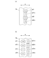
このような変更は、図9に示すように軸方向に並べられた磁気センサーの中から制御手段が選択して欠陥を探知するための磁場の検出に使用することでも達成できる。但し、図8に示す構成では軸方向の位置制御の分解能に依存するのに対し、図9に示す構成では軸方向の配置ピッチに依存する。
図9において使用する磁気センサーとして、磁気センサーユニット4a,4b,4c,4d,4e,4fに搭載のものを選択したり、磁気センサーユニット4a,4c,4eに搭載のものを選択したり、(及び他の組として磁気センサーユニット4b,4d,4fに搭載のものを選択したり)、磁気センサーユニット4c,4dに搭載のものを選択したり、磁気センサーユニット4b,4eに搭載のものを選択したりなどの選択により、上記第1実施形態における所定距離PAを変更したり、上記第2実施形態における空間分解能を変更したりすることができる。
Such a change can also be achieved by using a magnetic field for detecting a defect selected by the control means from magnetic sensors arranged in the axial direction as shown in FIG. However, the configuration shown in FIG. 8 depends on the axial position control resolution, whereas the configuration shown in FIG. 9 depends on the axial arrangement pitch.
As a magnetic sensor to be used in FIG. 9, a sensor mounted on the
1 非破壊検査装置(パルス磁気検査装置)
2 断熱配管
2a 鋼管
2b 断熱材
2c 外筒
3−1 励磁コイル
3−2 励磁コイル
4a,4b,4c,・・・ 磁気センサーユニット
5 自走型移動体
6 走行用駆動回路
7 磁気センサー用回路
8 パルス電源
9 電源切り替え回路
10 コンピューター
11 コンピューター
12 可動検査部
13 リニアアクチュエータ
a01,a02,・・・ 磁気センサー
a01m,a02m,・・・ 磁気センサー
a01n,a02n,・・・ 磁気センサー
b01,b02,・・・ 磁気センサー
1 Nondestructive inspection equipment (pulse magnetic inspection equipment)
DESCRIPTION OF
Claims (9)
励磁コイル及び磁気センサーを搭載し、前記被検査配管の外側に配置され前記被検査配管の軸方向に移動する可動検査部と、
前記可動検査部の移動速度、前記励磁コイルに印加する電圧及び前記磁気センサーを制御する制御手段と、を備え、
前記励磁コイルは、前記被検査配管が挿通され、前記軸方向に互いに離れて配置される対で構成され、
前記磁気センサーは、前記軸方向に互いに離れた前記励磁コイルの間で、前記被検査配管の円周方向に1又は複数配置され、少なくとも前記軸方向に所定距離を隔てた位置に配置される複数で構成され、
前記制御手段は、前記電圧の周期又はその2以上の整数倍と前記可動検査部が前記所定距離分だけ移動するのに要する時間とが相等しくなるように制御することを特徴とする非破壊検査装置。 A non-destructive inspection device using magnetism for non-destructive inspection of defects in piping to be inspected,
A movable inspection unit that is equipped with an excitation coil and a magnetic sensor and is arranged outside the inspection pipe and moves in the axial direction of the inspection pipe;
A moving speed of the movable inspection unit, a voltage applied to the excitation coil and a control means for controlling the magnetic sensor,
The exciting coil is constituted by a pair in which the pipe to be inspected is inserted and arranged apart from each other in the axial direction,
One or a plurality of the magnetic sensors are arranged in the circumferential direction of the pipe to be inspected between the excitation coils that are separated from each other in the axial direction, and a plurality of magnetic sensors are arranged at least at a predetermined distance in the axial direction. Consists of
The control means controls the non-destructive inspection so that a period of the voltage or an integral multiple of 2 or more thereof is equal to a time required for the movable inspection unit to move by the predetermined distance. apparatus.
前記解析手段は、被検査配管上のある位置に異なるタイミングで配置された前記所定距離を隔てた位置に配置される複数の磁気センサーにより検出した信号の組に基づき、同位置を測定点とした前記欠陥に起因した信号を解析することを特徴とする請求項1又は請求項2に記載の非破壊検査装置。 Comprising an analyzing means for analyzing a signal detected by the magnetic sensor;
The analysis means uses the same position as a measurement point based on a set of signals detected by a plurality of magnetic sensors arranged at different positions arranged at different timings at a certain position on the pipe to be inspected. The nondestructive inspection apparatus according to claim 1, wherein a signal resulting from the defect is analyzed.
励磁コイル及び磁気センサーを搭載し、前記被検査配管の外側に配置され前記被検査配管の軸方向に移動する可動検査部と、
前記可動検査部の移動速度、前記励磁コイルに印加する電圧及び前記磁気センサーを制御する制御手段と、を備え、
前記励磁コイルは、前記被検査配管が挿通され、前記軸方向に互いに離れて配置される対で構成され、
前記磁気センサーは、前記軸方向に互いに離れた前記励磁コイルの間で、前記被検査配管の円周方向に並べられる複数で円周方向の列を構成し、かつ、当該円周方向の列を2列以上構成し、当該列に属する各磁気センサーは、隣接する他の列に属する磁気センサーに対して前記円周方向にオフセット配置されていることを特徴とする非破壊検査装置。 A non-destructive inspection device using magnetism for non-destructive inspection of defects in piping to be inspected,
A movable inspection unit that is equipped with an excitation coil and a magnetic sensor and is arranged outside the inspection pipe and moves in the axial direction of the inspection pipe;
A moving speed of the movable inspection unit, a voltage applied to the excitation coil and a control means for controlling the magnetic sensor,
The exciting coil is constituted by a pair in which the pipe to be inspected is inserted and arranged apart from each other in the axial direction,
The magnetic sensor comprises a plurality of circumferential rows arranged in the circumferential direction of the pipe to be inspected between the excitation coils separated from each other in the axial direction, and the circumferential rows are arranged in the circumferential direction. A non-destructive inspection apparatus comprising two or more rows, wherein each magnetic sensor belonging to the row is offset in the circumferential direction with respect to a magnetic sensor belonging to another adjacent row.
励磁コイル及び磁気センサーを搭載し、前記被検査配管の外側に配置され前記被検査配管の軸方向に移動する可動検査部と、
前記可動検査部の移動速度、前記励磁コイルに印加する電圧及び前記磁気センサーを制御する制御手段と、を備え、
前記励磁コイルは、前記被検査配管が挿通され、前記軸方向に互いに離れて配置される対で構成され、
前記磁気センサーは、前記軸方向に互いに離れた前記励磁コイルの間で、前記被検査配管の円周方向及び/又は軸方向に並べられる複数で構成され、
当該複数の磁気センサーには、前記被検査配管の中心軸に平行な方向の磁場を検出する磁気センサーと、前記中心軸に対しねじれ角を有する方向の磁場を検出する磁気センサー及び/又は前記中心軸と交わる直線に平行な方向の磁場を検出する磁気センサーとが含まれていることを特徴とする非破壊検査装置。 A non-destructive inspection device using magnetism for non-destructive inspection of defects in piping to be inspected,
A movable inspection unit that is equipped with an excitation coil and a magnetic sensor and is arranged outside the inspection pipe and moves in the axial direction of the inspection pipe;
A moving speed of the movable inspection unit, a voltage applied to the excitation coil and a control means for controlling the magnetic sensor,
The exciting coil is constituted by a pair in which the pipe to be inspected is inserted and arranged apart from each other in the axial direction,
The magnetic sensor is composed of a plurality arranged in the circumferential direction and / or the axial direction of the pipe to be inspected between the exciting coils separated from each other in the axial direction.
The plurality of magnetic sensors include a magnetic sensor that detects a magnetic field in a direction parallel to a central axis of the pipe to be inspected, a magnetic sensor that detects a magnetic field in a direction having a twist angle with respect to the central axis, and / or the center. A non-destructive inspection apparatus characterized by including a magnetic sensor for detecting a magnetic field in a direction parallel to a straight line intersecting with an axis.
励磁コイル及び磁気センサーを搭載し、前記被検査配管の外側に配置され前記被検査配管の軸方向に移動する可動検査部と、
前記可動検査部の移動速度、前記励磁コイルに印加する電圧及び前記磁気センサーを制御する制御手段と、を備え、
前記励磁コイルは、前記被検査配管が挿通され、前記軸方向に互いに離れて配置される対で構成され、
前記磁気センサーは、前記軸方向に互いに離れた前記励磁コイルの間で、前記被検査配管の円周方向に1又は複数配置され、少なくとも前記軸方向に所定距離を隔てた位置に配置される複数で構成され、当該所定距離が変更可能に可動支持されていることを特徴とする非破壊検査装置。 A non-destructive inspection device using magnetism for non-destructive inspection of defects in piping to be inspected,
A movable inspection unit that is equipped with an excitation coil and a magnetic sensor and is arranged outside the inspection pipe and moves in the axial direction of the inspection pipe;
A moving speed of the movable inspection unit, a voltage applied to the excitation coil and a control means for controlling the magnetic sensor,
The exciting coil is constituted by a pair in which the pipe to be inspected is inserted and arranged apart from each other in the axial direction,
One or a plurality of the magnetic sensors are arranged in the circumferential direction of the pipe to be inspected between the excitation coils that are separated from each other in the axial direction, and a plurality of magnetic sensors are arranged at least at a predetermined distance in the axial direction. A non-destructive inspection apparatus characterized in that the predetermined distance is movably supported.
励磁コイル及び磁気センサーを搭載し、前記被検査配管の外側に配置され前記被検査配管の軸方向に移動する可動検査部と、
前記可動検査部の移動速度、前記励磁コイルに印加する電圧及び前記磁気センサーを制御する制御手段と、を備え、
前記励磁コイルは、前記被検査配管が挿通され、前記軸方向に互いに離れて配置される対で構成され、
前記磁気センサーは、前記軸方向に互いに離れた前記励磁コイルの間で、前記被検査配管の円周方向に1又は複数配置され、少なくとも前記軸方向に並べられて配置され、
前記制御手段は、前記軸方向に並べられた磁気センサーの中から選択して前記欠陥を探知するための磁場の検出に使用することを特徴とする非破壊検査装置。 A non-destructive inspection device using magnetism for non-destructive inspection of defects in piping
A movable inspection unit that is equipped with an excitation coil and a magnetic sensor and is arranged outside the inspection pipe and moves in the axial direction of the inspection pipe;
A moving speed of the movable inspection unit, a voltage applied to the excitation coil and a control means for controlling the magnetic sensor,
The exciting coil is constituted by a pair in which the pipe to be inspected is inserted and arranged apart from each other in the axial direction,
One or a plurality of the magnetic sensors are arranged in the circumferential direction of the pipe to be inspected between the excitation coils separated from each other in the axial direction, and arranged at least in the axial direction,
The non-destructive inspection apparatus, wherein the control means is selected from magnetic sensors arranged in the axial direction and used to detect a magnetic field for detecting the defect.
Priority Applications (2)
| Application Number | Priority Date | Filing Date | Title |
|---|---|---|---|
| JP2014126125A JP2017138099A (en) | 2014-06-19 | 2014-06-19 | Nondestructive inspection apparatus |
| PCT/JP2015/067608 WO2015194635A1 (en) | 2014-06-19 | 2015-06-18 | Non-destructive inspection device |
Applications Claiming Priority (1)
| Application Number | Priority Date | Filing Date | Title |
|---|---|---|---|
| JP2014126125A JP2017138099A (en) | 2014-06-19 | 2014-06-19 | Nondestructive inspection apparatus |
Publications (1)
| Publication Number | Publication Date |
|---|---|
| JP2017138099A true JP2017138099A (en) | 2017-08-10 |
Family
ID=54935613
Family Applications (1)
| Application Number | Title | Priority Date | Filing Date |
|---|---|---|---|
| JP2014126125A Pending JP2017138099A (en) | 2014-06-19 | 2014-06-19 | Nondestructive inspection apparatus |
Country Status (2)
| Country | Link |
|---|---|
| JP (1) | JP2017138099A (en) |
| WO (1) | WO2015194635A1 (en) |
Cited By (4)
| Publication number | Priority date | Publication date | Assignee | Title |
|---|---|---|---|---|
| KR20190018284A (en) * | 2017-08-14 | 2019-02-22 | 조선대학교산학협력단 | A nondestructive testing apparatus including spiral direction current induction means |
| KR102169144B1 (en) * | 2019-12-27 | 2020-10-23 | 주식회사 미성 | Coating Inspection Apparatus Composite Pipe |
| KR102200900B1 (en) * | 2019-07-12 | 2021-01-08 | 임재생 | Apparatus For Non-destructive Inspection For Pipes |
| US20220113283A1 (en) * | 2020-10-12 | 2022-04-14 | Russell Nde Systems Inc. | Method and apparatus for the detection of corrosion under insulation (cui), corrosion under fireproofing (cuf), and far side corrosion on carbon steel piping and plates |
Families Citing this family (1)
| Publication number | Priority date | Publication date | Assignee | Title |
|---|---|---|---|---|
| US10139372B1 (en) * | 2017-05-19 | 2018-11-27 | Saudi Arabian Oil Company | Two-stage corrosion under insulation detection methodology and modular vehicle with dual locomotion sensory systems |
Family Cites Families (7)
| Publication number | Priority date | Publication date | Assignee | Title |
|---|---|---|---|---|
| JPH0737963B2 (en) * | 1989-09-29 | 1995-04-26 | 原電子測器株式会社 | Eddy current flaw detection coil device |
| JP3753499B2 (en) * | 1997-04-14 | 2006-03-08 | 株式会社竹中工務店 | Magnetic flaw detection apparatus and method |
| JP4650167B2 (en) * | 2005-08-29 | 2011-03-16 | Jfeエンジニアリング株式会社 | Defect detection method and defect detection apparatus |
| US7402999B2 (en) * | 2005-11-30 | 2008-07-22 | General Electric Company | Pulsed eddy current pipeline inspection system and method |
| JP4487082B1 (en) * | 2009-07-01 | 2010-06-23 | 国立大学法人 岡山大学 | Magnetic flux leakage flaw detection method and apparatus |
| JP5562629B2 (en) * | 2009-12-22 | 2014-07-30 | 三菱重工業株式会社 | Flaw detection apparatus and flaw detection method |
| JP5522699B2 (en) * | 2012-08-24 | 2014-06-18 | 国立大学法人 岡山大学 | Nondestructive inspection apparatus and nondestructive inspection method using pulse magnetism |
-
2014
- 2014-06-19 JP JP2014126125A patent/JP2017138099A/en active Pending
-
2015
- 2015-06-18 WO PCT/JP2015/067608 patent/WO2015194635A1/en active Application Filing
Cited By (6)
| Publication number | Priority date | Publication date | Assignee | Title |
|---|---|---|---|---|
| KR20190018284A (en) * | 2017-08-14 | 2019-02-22 | 조선대학교산학협력단 | A nondestructive testing apparatus including spiral direction current induction means |
| KR101977921B1 (en) | 2017-08-14 | 2019-05-13 | 조선대학교산학협력단 | A nondestructive testing apparatus including spiral direction current induction means |
| KR102200900B1 (en) * | 2019-07-12 | 2021-01-08 | 임재생 | Apparatus For Non-destructive Inspection For Pipes |
| KR102169144B1 (en) * | 2019-12-27 | 2020-10-23 | 주식회사 미성 | Coating Inspection Apparatus Composite Pipe |
| US20220113283A1 (en) * | 2020-10-12 | 2022-04-14 | Russell Nde Systems Inc. | Method and apparatus for the detection of corrosion under insulation (cui), corrosion under fireproofing (cuf), and far side corrosion on carbon steel piping and plates |
| US11493480B2 (en) * | 2020-10-12 | 2022-11-08 | Russell Nde Systems Inc. | Method and apparatus for the detection of corrosion under insulation (CUI), corrosion under fireproofing (CUF), and far side corrosion on carbon steel piping and plates |
Also Published As
| Publication number | Publication date |
|---|---|
| WO2015194635A1 (en) | 2015-12-23 |
Similar Documents
| Publication | Publication Date | Title |
|---|---|---|
| WO2015194635A1 (en) | Non-destructive inspection device | |
| JP5522699B2 (en) | Nondestructive inspection apparatus and nondestructive inspection method using pulse magnetism | |
| JP2007263946A (en) | Sensor and method for eddy current flaw detection | |
| WO2018138850A1 (en) | Magnetic body inspection device and magnetic body inspection method | |
| JP5695278B2 (en) | Equipment for detecting cracks in metallic materials in metal manufacturing processes | |
| JP4876248B2 (en) | Nondestructive inspection method and apparatus | |
| JPWO2016080229A1 (en) | Magnetic flaw detection apparatus and magnetic flaw detection method | |
| US8884614B2 (en) | Eddy current array probe | |
| CN106770636A (en) | A kind of magnetic drives formula Array eddy-current probe and method for defect inspection | |
| Rocha et al. | Studies to optimize the probe response for velocity induced eddy current testing in aluminium | |
| US7948233B2 (en) | Omnidirectional eddy current array probes and methods of use | |
| JP6594065B2 (en) | Rope inspection device and rope inspection system | |
| CN103868987A (en) | Eddy detection probe for detecting surface multiple cracks of conductive structure and detection method thereof | |
| CN105241951A (en) | Non-magnetic conductor material electromagnetic eddy current detection apparatus | |
| JP6209119B2 (en) | Flaw detection method and flaw detection system | |
| KR20180079989A (en) | Array eddy current probe with isolated transmit/receive part and eddy current inspection method using thereof | |
| JP4175181B2 (en) | Magnetic flux leakage flaw detector | |
| JP2017009549A (en) | Non destructive testing device | |
| JP2016173340A (en) | Pipeline inspection device | |
| JP2014066654A (en) | Electromagnetic acoustic transducer and electromagnetic acoustic flaw detector | |
| JP6882117B2 (en) | Exciting coil, non-destructive inspection device, and non-destructive inspection method | |
| KR20190061933A (en) | Lissajour curve display apparatus using magnetic sensor array | |
| Zhang et al. | A stress defect state measurement method based on low-frequency ACMFL excitation and Hall sensor array collection | |
| CN206945608U (en) | Magnetosensitive phased array probe assembly | |
| EP3617698A1 (en) | Method for detecting surface breaking defects in the hardened surface of a bearing component, especially of a bearing of a wind turbine |