JPWO2016080229A1 - Magnetic flaw detection apparatus and magnetic flaw detection method - Google Patents
Magnetic flaw detection apparatus and magnetic flaw detection method Download PDFInfo
- Publication number
- JPWO2016080229A1 JPWO2016080229A1 JP2016560151A JP2016560151A JPWO2016080229A1 JP WO2016080229 A1 JPWO2016080229 A1 JP WO2016080229A1 JP 2016560151 A JP2016560151 A JP 2016560151A JP 2016560151 A JP2016560151 A JP 2016560151A JP WO2016080229 A1 JPWO2016080229 A1 JP WO2016080229A1
- Authority
- JP
- Japan
- Prior art keywords
- magnetic
- detection
- defect
- inspection object
- magnetic field
- Prior art date
- Legal status (The legal status is an assumption and is not a legal conclusion. Google has not performed a legal analysis and makes no representation as to the accuracy of the status listed.)
- Pending
Links
Images


Classifications
-
- G—PHYSICS
- G01—MEASURING; TESTING
- G01N—INVESTIGATING OR ANALYSING MATERIALS BY DETERMINING THEIR CHEMICAL OR PHYSICAL PROPERTIES
- G01N27/00—Investigating or analysing materials by the use of electric, electrochemical, or magnetic means
- G01N27/72—Investigating or analysing materials by the use of electric, electrochemical, or magnetic means by investigating magnetic variables
- G01N27/82—Investigating or analysing materials by the use of electric, electrochemical, or magnetic means by investigating magnetic variables for investigating the presence of flaws
- G01N27/83—Investigating or analysing materials by the use of electric, electrochemical, or magnetic means by investigating magnetic variables for investigating the presence of flaws by investigating stray magnetic fields
- G01N27/87—Investigating or analysing materials by the use of electric, electrochemical, or magnetic means by investigating magnetic variables for investigating the presence of flaws by investigating stray magnetic fields using probes
-
- G—PHYSICS
- G01—MEASURING; TESTING
- G01N—INVESTIGATING OR ANALYSING MATERIALS BY DETERMINING THEIR CHEMICAL OR PHYSICAL PROPERTIES
- G01N27/00—Investigating or analysing materials by the use of electric, electrochemical, or magnetic means
- G01N27/72—Investigating or analysing materials by the use of electric, electrochemical, or magnetic means by investigating magnetic variables
- G01N27/82—Investigating or analysing materials by the use of electric, electrochemical, or magnetic means by investigating magnetic variables for investigating the presence of flaws
- G01N27/90—Investigating or analysing materials by the use of electric, electrochemical, or magnetic means by investigating magnetic variables for investigating the presence of flaws using eddy currents
Landscapes
- Chemical & Material Sciences (AREA)
- Chemical Kinetics & Catalysis (AREA)
- Electrochemistry (AREA)
- Physics & Mathematics (AREA)
- Health & Medical Sciences (AREA)
- Life Sciences & Earth Sciences (AREA)
- Analytical Chemistry (AREA)
- Biochemistry (AREA)
- General Health & Medical Sciences (AREA)
- General Physics & Mathematics (AREA)
- Immunology (AREA)
- Pathology (AREA)
- Investigating Or Analyzing Materials By The Use Of Magnetic Means (AREA)
Abstract
本発明にかかる磁気探傷装置および磁気探傷方法は、被検査物に磁界を印加し、前記被検査物の外面から互いに異なる複数の第1検出位置で磁気を検出し、これら各検出結果に基づいて、前記被検査物に対し離接する第1方向に沿った、前記被検査物における所定の欠陥の位置を求める。A magnetic flaw detection apparatus and a magnetic flaw detection method according to the present invention apply a magnetic field to an inspection object, detect magnetism at a plurality of first detection positions different from each other from the outer surface of the inspection object, and based on these detection results Then, a position of a predetermined defect in the inspection object along a first direction that is separated from and in contact with the inspection object is obtained.
Description
本発明は、磁気を検出する磁気検出部を用いることによって被検査物における所定の欠陥(異常)を探傷する磁気探傷装置および磁気探傷方法に関する。 The present invention relates to a magnetic flaw detection apparatus and a magnetic flaw detection method for detecting a predetermined defect (abnormality) in an inspection object by using a magnetic detection unit that detects magnetism.
鋼管、鉄管およびアルミ管等の金属管の傷や薄肉化(減肉)等の欠陥(異常)の有無を検査する方法は、目視による外観観察の他、主に、超音波を利用した超音波探傷法や、磁気を利用した磁気探傷法等がある。この磁気探傷法として、一般に、被検査物に直流磁場(直流磁界)または交流磁場(交流磁界)を与え欠陥によって生じた磁束(欠陥漏洩磁束)を検出する漏洩磁束探傷法(例えば特許文献1参照)、および、被検査物に交流磁場で誘起される渦電流における欠陥による変化を検出する渦電流探傷法(例えば特許文献2参照)が知られており、さらに、近年では、空間的に均質な磁場(磁界)を発生させるヘルムホルツコイルを用いた磁気探傷装置(ヘルムホルツ型磁気探傷装置)も提案されている(例えば特許文献3参照)。 The method of inspecting the presence or absence of defects (abnormalities) such as scratches and thinning (thinning) of metal pipes such as steel pipes, iron pipes and aluminum pipes is mainly ultrasonic using ultrasonic waves in addition to visual observation. There are a flaw detection method and a magnetic flaw detection method using magnetism. As this magnetic flaw detection method, in general, a leakage magnetic flux flaw detection method for detecting a magnetic flux (defect leakage magnetic flux) generated by a defect by applying a DC magnetic field (DC magnetic field) or an AC magnetic field (AC magnetic field) to an inspection object (see, for example, Patent Document 1). ), And an eddy current flaw detection method (see, for example, Patent Document 2) for detecting a change caused by a defect in an eddy current induced in an AC magnetic field in an object to be inspected is known. A magnetic flaw detector (Helmholtz type magnetic flaw detector) using a Helmholtz coil that generates a magnetic field (magnetic field) has also been proposed (see, for example, Patent Document 3).
ところで、磁性体や導体等の材料によって形成された互いに径の異なる複数の筒状体を径方向で複数多重した、例えば断熱管等の多重構造管を被検査物として探傷する場合、前記特許文献1や前記特許文献2に開示された方法では、最も外側に位置する管の方がそれよりも内側に位置する管に較べて著しく磁場変化が大きく、内側の管を探傷することが難しい。一方、前記特許文献3に開示されたヘルムホルツコイル型磁気探傷装置は、二重構造管の断熱管を被検査物として探傷しているが、磁場の変化で欠陥を検出したとしても、断熱管の外周面上に配設された1個の磁気センサではこの欠陥が内側の管に生じているのか外側の管に生じているのかを区別することが難しい。
By the way, when flaw detection is performed as an inspection object, for example, a multi-structure tube such as a heat insulating tube, in which a plurality of cylindrical bodies having different diameters formed from materials such as a magnetic body and a conductor are radially multiplexed. In the method disclosed in No. 1 or
本発明は、上述の事情に鑑みて為された発明であり、その目的は、被検査物に対し離接する第1方向に沿った、被検査物における所定の欠陥の位置を求めることができる磁気探傷装置および磁気探傷方法を提供することである。 The present invention has been made in view of the above-described circumstances, and its object is to provide a magnetism that can determine the position of a predetermined defect in the inspection object along the first direction that is in contact with the inspection object. A flaw detection apparatus and a magnetic flaw detection method are provided.
本発明にかかる磁気探傷装置および磁気探傷方法は、被検査物に対し離接する第1方向に沿った、被検査物における所定の欠陥の位置を求めることができる。 The magnetic flaw detection apparatus and the magnetic flaw detection method according to the present invention can determine the position of a predetermined defect in the inspection object along the first direction in which the inspection object is separated from and in contact with the inspection object.
本発明にかかる磁気探傷装置および磁気探傷方法は、被検査物に磁界を印加し、前記被検査物の外面から互いに異なる複数の第1検出位置で磁気を検出し、これら各検出結果に基づいて、前記被検査物に対し離接する第1方向に沿った、前記被検査物における所定の欠陥の位置を求める。 A magnetic flaw detection apparatus and a magnetic flaw detection method according to the present invention apply a magnetic field to an inspection object, detect magnetism at a plurality of first detection positions different from each other from the outer surface of the inspection object, and based on these detection results Then, a position of a predetermined defect in the inspection object along a first direction that is separated from and in contact with the inspection object is obtained.
上記並びにその他の本発明の目的、特徴及び利点は、以下の詳細な記載と添付図面から明らかになるであろう。 The above and other objects, features and advantages of the present invention will become apparent from the following detailed description and the accompanying drawings.
以下、本発明にかかる実施の一形態を図面に基づいて説明する。なお、各図において同一の符号を付した構成は、同一の構成であることを示し、適宜、その説明を省略する。また、本明細書において、総称する場合には添え字を省略した参照符号で示し、個別の構成を指す場合には添え字を付した参照符号で示す。 Hereinafter, an embodiment according to the present invention will be described with reference to the drawings. In addition, the structure which attached | subjected the same code | symbol in each figure shows that it is the same structure, The description is abbreviate | omitted suitably. Further, in this specification, when referring generically, it is indicated by a reference symbol without a suffix, and when referring to an individual configuration, it is indicated by a reference symbol with a suffix.
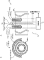
図1は、実施形態における磁気探傷装置の構成を示す図である。図1Aは、全体構成を示し、図1Bは、磁界印加部周辺の断面図である。図2は、実施形態の磁気探傷装置で検査される被検査物の外観を示す斜視図である。図3は、実施形態の磁気探傷装置における欠陥の位置の算出方法を説明するための図である。 FIG. 1 is a diagram illustrating a configuration of a magnetic flaw detector according to an embodiment. 1A shows the overall configuration, and FIG. 1B is a cross-sectional view around the magnetic field application unit. FIG. 2 is a perspective view showing an appearance of an object to be inspected by the magnetic flaw detector according to the embodiment. FIG. 3 is a diagram for explaining a method for calculating a defect position in the magnetic flaw detector according to the embodiment.
実施形態における磁気探傷装置は、検査対象の被検査物に、磁界を印加し、被検査物の所定の欠陥(異常)に起因して生じる磁場の変化を、被検査物に対し離接する第1方向に沿って、被検査物の外面から互いに異なる距離の複数の第1検出位置それぞれで検出し、これら各検出結果に基づいて、第1方向に沿った、被検査物における所定の欠陥の位置を求める装置である。このような実施形態における磁気探傷装置Mは、例えば、図1に示すように、磁界印加部1aと、第1群検出部3aと、欠陥位置処理部42を備える制御処理部4と備え、図1に示す例では、さらに、入力部5と、出力部6と、インターフェース部(IF部)7とを備える。
The magnetic flaw detection apparatus according to the first embodiment applies a magnetic field to an inspection object to be inspected, and first contacts and disconnects the change in the magnetic field caused by a predetermined defect (abnormality) of the inspection object. Detected at a plurality of first detection positions at different distances from the outer surface of the inspection object along the direction, and based on each detection result, the position of a predetermined defect in the inspection object along the first direction Is a device for obtaining The magnetic flaw detector M in such an embodiment includes, for example, as shown in FIG. 1, a magnetic
磁界印加部1aは、被検査物SPに磁界を印加する装置である。被検査物SPは、好ましくは、鋼管、鉄管およびアルミ管等の金属管SPaであり、より好ましくは、例えば磁性体や導体等の材料によって形成された互いに径の異なる複数の筒状体を径方向で複数多重した多重構造管である。図1に示す例では、被検査物SPは、図2に示す二重構造管の断熱管SPaである。この断熱管SPaは、図2に示すように、例えば、内側に位置する鋼管SPa1と、前記鋼管SPa1の外周を所定の厚さで覆う断熱材SPa2と、前記断熱材SPa2の外周を覆う、外側に位置する外装板金である溶融亜鉛鉄板SPa3とを備えて構成される。磁界印加部1aは、励磁コイル11aと、電源部12とを備える。
The magnetic
励磁コイル11aは、電源部12から電力の供給を受けることによって、磁場を生成し、この生成した磁場を被検査物SPに与える装置である。励磁コイル11aは、漏洩磁束探傷法や渦電流探傷法等の探傷方法に応じて種々の公知の装置を用いることができる。例えば、漏洩磁束探傷法では、励磁コイル11aは、直流磁場または交流磁場を与えることによって被検査物SP内に磁束を生じさせるように構成される。また例えば、渦電流探傷法では、励磁コイル11aは、交流磁場を与えることによって被検査物SPに渦電流を生じさせるように構成される。本実施形態では、第1態様としての励磁コイル11aは、図1に示す1対の第1および第2励磁コイル11a−1、11a−2を備える。
The
これら1対の第1および第2励磁コイル11a−1、11a−2は、断熱管SPaをその各芯部に挿通させ、断熱管SPaにおける軸方向に沿って所定の間隔で離間して配置される。前記所定の間隔は、適宜に設定され、例えば、ヘルムホルツコイルを構成するために、第1および第2励磁コイル11a−1、11a−2の半径に略等しい長さである。第1励磁コイル11a−1は、比較的短い高さ(短高)の筒状体である第1コイルボビン111a−1に、例えば断面丸形や断面角形等の長尺な電気伝導性を持つ線材である第1導体部材112a−1を、例えば樹脂や油紙等の絶縁材料を介して巻回すことによって形成される。同様に、第2励磁コイル11a−2は、短高の筒状体である第2コイルボビン111a−2に、例えば断面丸形や断面角形等の長尺な電気伝導性を持つ線材である第2導体部材112a−2を、例えば樹脂や油紙等の絶縁材料を介して巻回すことによって形成される。第1および第2コイルボビン111a−1、111a−2は、例えば樹脂材料等の非磁性絶縁体で形成される。このような第1および第2励磁コイル11a−1、11a−2のターン数は、第1および第2励磁コイル11a−1、11a−2によって生成したい所望の磁場の強度等に応じて適宜に設定される。第1および第2導体部材112a−1、112a−2それぞれは、例えば、銅やアルミニウム等の比較的高い導電性を持ち、樹脂で絶縁被覆された導体線である。第1および第2励磁コイル11a−1、11a−2は、互いに直列に接続されている。より具体的には、第1励磁コイル11a−1の一方端は、電源部12に接続され、その他方端は、第2励磁コイル11a−2の一方端に接続され、その他方端は、電源部12に接続される。
The pair of first and second
電源部12は、制御処理部4に接続され、制御処理部4の制御に従って、励磁コイル11aに電力を給電することによって磁気(磁界)を発生させるための装置である。電源部12は、直流電流、交流電流およびパルス電流等の、探傷方法に応じた所定の電流を1対の第1および第2励磁コイル11a−1、11a−2に給電することによって直流磁場、交流磁場およびパルス状の磁場(パルス磁場)等の、前記探傷方法に応じた所定の磁場を発生させる。なお、電源部2は、1対の第1および第2励磁コイル11a−11a−2に、逆相の電流や一方のみに電流を給電するために、第1および第2励磁コイル11a−1、11a−2への各通電路を適宜に切り換える切替回路を備えて良い。
The
第1群検出部3aは、磁気を検出する複数の第1磁気検出部31aを備える。これら複数の第1磁気検出部31aは、1対の励磁コイル11a−1、11a−2間であって、被検査物SPの外面上(直上および上方を含む。ここで、上方とは、外面から外側へ離れる方向を意味する。)に、被検査物SPに対し離接する第1方向に沿って、前記外面から互いに異なる距離の複数の第1検出位置に配置される。これら複数の第1磁気検出部31aそれぞれは、制御処理部4に接続され、探傷方法に応じた磁気を検出し、その検出結果を制御処理部4へ出力する。例えば、漏洩磁束探傷法では、欠陥によって生じた漏洩磁束に起因する磁気が検出される。また例えば、渦電流探傷法では、欠陥によって生じた渦電流の変化に起因する磁気が検出される。図1に示す例では、第1群検出部3aは、3個の第1磁気検出部31a−1〜31a−3を備えて構成される。これら3個の第1磁気検出部31a−1〜31a−3は、1対の励磁コイル11a−1、11a−2間であって、断熱管SPaの外周面上に、断熱管SPaの径方向に沿って、前記外周面から互いに異なる第1ないし第3距離の3個の第1検出位置に配置されている。
The first
第1磁気検出部31aとして、各種の磁気センサが利用可能である。より具体的には、第1磁気検出部31aには、磁場により電気抵抗が変化する磁気抵抗効果を利用した磁気抵抗素子(MR素子)を用いた磁気センサ、高透磁率合金磁性体の表皮効果で磁場によりインピーダンスが変化する磁気インピーダンス効果を利用した磁気インピーダンス素子を用いた磁気センサ、ホール効果を利用したホール素子を用いた磁気センサ、高透磁率材料の磁化飽和性を利用したフラックス・ゲートを用いた磁気センサ、および、2箇所にジョセフソン接合を持つ超伝導体のリングを利用した超伝導量子干渉素子(SQUID、Superconducting Quantum Interference Device)を用いた磁気センサ素子等が用いられる。
Various magnetic sensors can be used as the first
入力部5は、制御処理部4に接続され、例えば、被検査物SPの測定を指示するコマンド等の各種コマンド、および、例えば被検査物SPにおける識別子(例えば被検査物の整理番号等)の入力等の測定する上で必要な各種データを磁気探傷装置Mに入力する機器であり、例えば、所定の機能を割り付けられた複数の入力スイッチや、キーボードや、マウス等である。出力部6は、制御処理部4に接続され、制御処理部4の制御に従って、入力部5から入力されたコマンドやデータ、および、磁気探傷装置Mによって測定された被検査物SPの測定結果(例えば、磁気検出部3の測定データ、欠陥の有無および欠陥の位置)等を出力する機器であり、例えばCRTディスプレイ、LCD(液晶ディスプレイ)および有機ELディスプレイ等の表示装置やプリンタ等の印刷装置等である。
The
なお、入力部5および出力部6からタッチパネルが構成されてもよい。このタッチパネルを構成する場合において、入力部5は、例えば抵抗膜方式や静電容量方式等の操作位置を検出して入力する位置入力装置であり、出力部6は、表示装置である。このタッチパネルでは、表示装置の表示面上に位置入力装置が設けられ、表示装置に入力可能な1または複数の入力内容の候補が表示され、ユーザが、入力したい入力内容を表示した表示位置を触れると、位置入力装置によってその位置が検出され、検出された位置に表示された表示内容がユーザの操作入力内容として磁気探傷装置Mに入力される。このようなタッチパネルでは、ユーザは、入力操作を直感的に理解し易いので、ユーザにとって取り扱い易い磁気探傷装置Mが提供される。
A touch panel may be configured from the
IF部7は、制御処理部4に接続され、制御処理部4の制御に従って、外部機器との間でデータの入出力を行う回路であり、例えば、シリアル通信方式であるRS−232Cのインターフェース回路、Bluetooth(登録商標)規格を用いたインターフェース回路、IrDA(Infrared Data Asscoiation)規格等の赤外線通信を行うインターフェース回路、および、USB(Universal Serial Bus)規格を用いたインターフェース回路等である。
The
制御処理部4は、磁気探傷装置Mの各部を当該各部の機能に応じてそれぞれ制御するための回路である。制御処理部4は、例えば、CPU(Central Processing Unit)、メモリおよびそれら周辺回路を備えたマイクロコンピュータを備えて構成される。制御処理部4には、プログラムを実行することによって、制御部41および欠陥位置処理部42が機能的に構成される。
The
制御部41は、磁気探傷装置Mの各部を当該各部の機能に応じてそれぞれ制御するためのものである。
The
欠陥位置処理部42は、第1群検出部3aにおける複数の第1磁気検出部31aの各検出結果に基づいて、前記第1方向に沿った、被検査物SPにおける所定の欠陥の位置を求めるものである。上述の例では、欠陥位置処理部42は、第1群検出部3aにおける3個の第1磁気検出部31a−1〜31a−3の各検出結果に基づいて、断熱管SPaの径方向に沿った、断熱管SPaにおける所定の欠陥の位置を求めるものである。
The defect
そして、好ましくは、欠陥位置処理部42は、下記条件1および条件2を用いることによって、第1群検出部3aにおける複数の第1磁気検出部31aの各検出結果に基づいて、被検査物SPの外面以内であって前記第1方向に沿った前記外面から互いに異なる距離の複数の被観測位置における各磁界強度を求め、この求めた複数の被観測位置における各磁界強度に基づいて、被検査物SPにおける所定の欠陥の位置を求めるものである。
条件1;第1磁気検出部31aの検出結果は、複数の被観測位置での各磁界が複数の被観測位置から当該第1磁気検出部31aの第1検出位置まで伝播してきた各磁界の各磁界強度の和であること
条件2;前記磁界強度は、被観測位置および第1検出位置間の距離と特定の関係があることPreferably, the defect
Condition 1: The detection result of the first
より詳しくは、欠陥位置処理部42は、次のように、欠陥の位置を求めている。一般に、被観測位置の磁界強度をMI0とすると、第1検出位置における磁界強度MIは、上記条件2として、被観測位置および第1検出位置間の距離Lの二乗に反比例して減衰する(MI=k×(MI0/L2)、kは比例定数)。このため、断熱管SPaにおいて、図3に示すように、横軸Xを、鋼管SPa1の外周面を座標原点とした、鋼管SPa1の外周面からの径方向に沿った距離とし、縦軸Yを磁界強度MIとし、鋼管SPa1での磁界強度MIをMI01とし、外装板金の溶融亜鉛鉄板SPa3での磁界強度MIをMI02とし、鋼管SPa1の外周面から溶融亜鉛鉄板SPa3の外周面までの距離をX0とした場合、鋼管SPa1の外周面からの径方向に沿った距離X1の第1検出位置に配置された第1磁気検出部31a−1は、上記条件1を満たし、α(X1)=k×(MI01/X12)+k×(MI02/(X1−X0)2)を検出する。同様に、鋼管SPa1の外周面からの径方向に沿った距離X2の第1検出位置に配置された第1磁気検出部31a−2は、上記条件1を満たし、α(X2)=k×(MI01/X22)+k×(MI02/(X2−X0)2)を検出する。鋼管SPa1の外周面からの径方向に沿った距離X3の第1検出位置に配置された第1磁気検出部31a−3は、上記条件1を満たし、α(X3)=k×(MI01/X32)+k×(MI02/(X3−X0)2)を検出する。ここで、比例定数kおよび距離X0、X1、X2、X3は、既知であり、各検出結果α(X)は、第1磁気検出部31a−1〜31a−3の測定で測定値として得られるので、上記3個の式のうちの2個の式を用いることで、鋼管SPa1での磁界強度MI01および溶融亜鉛鉄板SPa3での磁界強度MI02が求められる。あるいは、第1磁気検出部31a−1〜31a−3の各検出結果に、最も合う(フィットする)曲線α(X)が例えば最小二乗法等によって求められ、この求めた曲線α(X)から、予め設定された互いに異なる所定の2箇所の位置XA、XB(XA、XB>0)で、2個の式、α(XA)=k×(MI01/XA2)+k×(MI02/(XA−X0)2)、α(XB)=k×(MI01/XB2)+k×(MI02/(XB−X0)2)が生成され、これら2個の式を用いることで、鋼管SPa1での磁界強度MI01および溶融亜鉛鉄板SPa3での磁界強度MI02が求められてもよい。なお、図3に示す曲線β1(X)は、被観測位置を鋼管SPa1の外周面とした場合、その磁場における磁界強度β1(X)と外周面からの距離Xとの関係を示し、曲線β2(X)は、被観測位置を溶融亜鉛鉄板SPa3の外周面とした場合、その磁場における磁界強度β2(X)と外周面からの距離Xとの関係を示し、曲線α(X)は、外周面からの距離Xの位置に位置する第1磁気検出部3aで検出される磁界強度α(X)、すなわち、α(X)=β1(X)+β2(X)を示す。More specifically, the defect
そして、断熱管SPaに欠陥の無い状態で、予め求められた鋼管SPa1での磁界強度MIref1とこの求めた鋼管SPa1での磁界強度MI01とが比較され、欠陥の有無が判定される。この判定の結果、鋼管SPa1での磁界強度MIref1と磁界強度MI01との差異が、ノイズを考慮した所定の第1範囲th1内である場合には、欠陥が無いと判定され、鋼管SPa1での磁界強度MIref1と磁界強度MI01との差異が、前記所定の第1範囲th1を越えている場合には、欠陥が有ると判定され、相対的に径方向内側に位置する内管の鋼管SPa1に欠陥があると判定される。断熱管SPaに欠陥の無い状態で、予め求められた溶融亜鉛鉄板SPa3での磁界強度MIref2とこの求めた溶融亜鉛鉄板SPa3での磁界強度MI02とが比較され、欠陥の有無が判定される。この判定の結果、溶融亜鉛鉄板SPa3での磁界強度MIref2と磁界強度MI02との差異が、ノイズを考慮した所定の第2範囲th2内である場合には、欠陥が無いと判定され、溶融亜鉛鉄板SPa3での磁界強度MIref2と磁界強度MI02との差異が、前記所定の第2範囲th2を越えている場合には、欠陥が有ると判定され、相対的に径方向外側に位置する外管の溶融亜鉛鉄板SPa3に欠陥があると判定される。すなわち、径方向に沿った欠陥の位置が判定できる。あるいは、後述するように、周方向に複数の第2群検出部3b(図4参照)を備える場合では、欠陥の有無の判定は、周方向の各位置で求められた鋼管SPa1での各磁界強度MI01を相互に比較することによって、実施されても良く、相違する場合に、その位置で鋼管SPa1に欠陥があると判定され、そして、周方向の各位置で求められた溶融亜鉛鉄板SPa3での各磁界強度MI02を相互に比較することによって、実施されても良く、相違する場合に、その位置で溶融亜鉛鉄板SPa3に欠陥があると判定される。また、後述するように、軸方向に複数の第3群検出部3c(図5参照)を備える場合では、欠陥の有無の判定は、軸方向の各位置で求められた鋼管SPa1での各磁界強度MI01を相互に比較することによって、実施されても良く、相違する場合に、その位置で鋼管SPa1に欠陥があると判定され、そして、軸方向の各位置で求められた溶融亜鉛鉄板SPa3での各磁界強度MI02を相互に比較することによって、実施されても良く、相違する場合に、その位置で溶融亜鉛鉄板SPa3に欠陥があると判定される。予め求められた欠陥のない状態の断熱管SPaのデータが存在する場合は、前述の実測データαに測定値そのものではなく上記欠陥のない状態との差分を用いても良い。この場合は、そのまま磁界強度MI01と磁界強度MIre1、磁界強度MI02と磁界強度MIref2を比較することができる。
Then, in a state where there is no defect in the heat insulating pipe SPa, the magnetic field intensity MIref1 in the steel pipe SPa1 obtained in advance is compared with the magnetic field intensity MI01 in the obtained steel pipe SPa1, and the presence or absence of the defect is determined. As a result of this determination, when the difference between the magnetic field intensity MIref1 and the magnetic field intensity MI01 in the steel pipe SPa1 is within the predetermined first range th1 in consideration of noise, it is determined that there is no defect, and the magnetic field in the steel pipe SPa1 is determined. If the difference between the intensity MIref1 and the magnetic field intensity MI01 exceeds the predetermined first range th1, it is determined that there is a defect, and the inner steel pipe SPa1 located relatively radially inside has a defect. It is determined that there is. In a state where there is no defect in the heat insulating pipe SPa, the magnetic field strength MIref2 obtained in the molten zinc iron plate SPa3 and the magnetic field strength MI02 obtained in the molten zinc iron plate SPa3 are compared, and the presence or absence of the defect is determined. As a result of the determination, if the difference between the magnetic field strength MIref2 and the magnetic field strength MI02 in the molten zinc iron plate SPa3 is within the predetermined second range th2 in consideration of noise, it is determined that there is no defect, and the molten zinc iron plate If the difference between the magnetic field strength MIref2 and the magnetic field strength MI02 at SPa3 exceeds the predetermined second range th2, it is determined that there is a defect, and the outer tube located relatively radially outside is melted. It is determined that the zinc iron plate SPa3 has a defect. That is, the position of the defect along the radial direction can be determined. Alternatively, as will be described later, in the case where a plurality of second
このように磁気探傷装置Mは、これら求めた複数の被観測位置における各磁界強度と、欠陥の無い正常状態の磁界強度と比較することで、欠陥の有無を判定でき、その結果、欠陥の位置を求めることができる。 In this way, the magnetic flaw detector M can determine the presence or absence of a defect by comparing the magnetic field strengths at the obtained plurality of observed positions with the magnetic field strengths in a normal state without defects. As a result, the position of the defect Can be requested.
また好ましくは、被検査物SPは、互いに径の異なる複数の筒状体を径方向で複数多重した多重構造管であり、欠陥位置処理部42は、第1群検出部3aにおける複数の第1磁気検出部31aのうちの2個の第1磁気検出部31aを選択し、この選択した2個の第1磁気検出部31aのうちの第1方向に沿った前記外面からの距離が遠い第1磁気検出部31aの検出結果から、前記選択した2個の第1磁気検出部31aのうちの第1方向に沿った前記外面からの距離が近い第1磁気検出部31aの検出結果を前記遠い第1磁気検出部31aの前記外面からの距離の二乗で除した除算結果を減算し、この減算した減算結果と所定の判定閾値とを比較することによって、被検出物SPにおける複数の筒状体のうちの最外側に位置する筒状体を除く他の筒状体に欠陥があるか否かを、被検査物SPにおける所定の欠陥の位置として求めるものである。
Preferably, the inspection object SP is a multiple structure tube in which a plurality of cylindrical bodies having different diameters are multiplexed in the radial direction, and the defect
より詳しくは、欠陥位置処理部42は、次のように、欠陥の位置を求めている。例えば、第1磁気検出部31a−1が溶融亜鉛鉄板SPa3の外周面から距離1mmの第1検出位置に位置し、第1磁気検出部31a−2が溶融亜鉛鉄板SPa3の外周面から距離5mmの第1検出位置に位置する場合、欠陥位置処理部42は、これら2個の第1磁気検出部31a−1、31a−2のうちの径方向に沿った前記外周面からの距離Xが遠い第1磁気検出部31a−2の検出結果α(5mm)から、これら2個の第1磁気検出部31a−1、31a−2のうちの径方向に沿った前記外周面からの距離Xが近い第1磁気検出部31a−1の検出結果α(1mm)を前記遠い第1磁気検出部31a−2の前記外周面からの距離5mmの二乗で除した除算結果α(1mm)/25を減算し(α(5mm)−α(1mm)/25=αsub)、この減算した減算結果αsubと所定の判定閾値th3とを比較することによって、断熱管SPaにおける相対的に外側に位置する外管の溶融亜鉛鉄板SPa3を除く他の管、すなわち、相対的に内側に位置する内管の鋼管SPa1に欠陥があるか否かを、被検査物SPにおける所定の欠陥の位置として求める。磁界強度が距離の二乗に反比例して減衰するので、内管の鋼管SPa1に欠陥がなく外管の鋼管SPa3に欠陥があれば、第1磁気検出部31a−1の検出結果α(1mm)と第1磁気検出部31a−2の検出結果α(5mm)との差が相対的に大きく、内管の鋼管SPa1に欠陥があり外管の鋼管SPa3に欠陥がなければ、第1磁気検出部31a−1の検出結果α(1mm)と第1磁気検出部31a−2の検出結果α(5mm)との差が相対的に小さいとの考えから、前記判定閾値th3は、磁界印加部1aで印加される磁界の磁界強度に応じて適宜な値(例えば0に近い値等)に設定される。したがって、欠陥位置処理部42は、減算結果αsubが判定閾値th3以上である場合には、内管の鋼管SPa1に欠陥があると判定し、減算結果αsubが判定閾値th3未満である場合には、内管の鋼管SPa1に欠陥が無いと判定し、欠陥の位置を求める。なお、好ましくは、第1磁気検出部31a−1〜31a−3の各検出結果に、最も合う(フィットする)曲線α(X)が例えば最小二乗法等によって求められ、この求めた曲線α(X)から、第1磁気検出部31a−1の検出結果α(1mm)および第1磁気検出部31a−2の検出結果α(5mm)は、求められる。また、最外側に位置する溶融亜鉛鉄板SPaの外周面からの距離は、検出結果α(X)に強く影響し、溶融亜鉛鉄板SPaが変形している場合もあるので、各第1磁気検出部31a−1〜31a−3における溶融亜鉛鉄板SPaの外周面からの距離Xは、距離計等によって実測されても良い。
More specifically, the defect
このような磁気探傷装置CMは、磁界強度が距離の二乗に反比例して減衰することを利用することによって、最外側の筒状体よりも内側の筒状体での欠陥の有無を、被検査物SPにおける所定の欠陥の位置として簡易に求めることができる。特に、上述したように、断熱管SPaのように二重構造管の場合、相対的に外側に位置する外管(この例では溶融亜鉛鉄板SPa3)での欠陥か、相対的に内側に位置する内管(この例では鋼管SPa1)での欠陥かを判別すれば足りるので、上記磁気探傷装置CMは、被検査物SPが二重構造管である場合に、好適である。 Such a magnetic flaw detector CM uses the fact that the magnetic field strength attenuates in inverse proportion to the square of the distance, thereby checking the presence or absence of defects in the inner cylindrical body from the outermost cylindrical body. The position of the predetermined defect in the object SP can be easily obtained. In particular, as described above, in the case of a double structure pipe such as the heat insulating pipe SPa, it is a defect in the outer pipe (in this example, the molten zinc iron plate SPa3) located relatively outside or located relatively inside. Since it is sufficient to determine whether the defect is in the inner pipe (in this example, the steel pipe SPa1), the magnetic flaw detector CM is suitable when the inspection object SP is a double structure pipe.
このような磁気探傷装置Mでは、断熱管SPa等の被検査物SPを探傷する場合、まず、ユーザ(オペレータ)によって被検査物SPの1対の第1および第2励磁コイル11a−1、11a−2が所定の間隔を空けて配置される。そして、ユーザによって図略の電源スイッチがオンされると、制御処理部4は、必要な各部の初期化を実行し、プログラムの実行によって、制御処理部4には、制御部41および欠陥位置処理部42が機能的に構成される。
In such a magnetic flaw detector M, when a test object SP such as a heat insulation tube SPa is detected, first, a pair of first and second
ユーザによる探傷開始の指示を入力部5を介して受け付けると、制御部41は、電源部2によって1対の第1および第2励磁コイル11a−1、11a−2に探傷方法に応じた電流を給電する。これによって1対の第1および第2励磁コイル11a−1、11a−2は、探傷方法に応じた磁界(磁場)を生成し、被検査物SPに磁界を印加する。この磁界は、被検査物SPを伝わり、この磁界に起因する磁界が第1群検出部3aの複数の第1磁気検出部31aによって検出され、複数の第1磁気検出部31aは、各検出結果を制御処理部4へ出力する。そして、欠陥位置処理部42は、複数の第1磁気検出部31aの各検出結果に基づいて被検査物SPにおける所定の欠陥の有無を判定し、第1方向に沿った欠陥の位置を判定する。制御部41は、複数の第1磁気検出部31aの各検出結果、欠陥の有無および第1方向に沿った欠陥の位置を出力部6へ出力する。なお、制御部41は、必要に応じて、複数の第1磁気検出部31aの各検出結果、欠陥の有無および第1方向に沿った欠陥の位置をIF部7を介して図略の外部機器へ出力しても良い。
When receiving an instruction to start flaw detection by the user via the
以上説明したように、本実施形態における磁気探傷装置Mおよびこれに実装された磁気探傷方法は、被検査物SPの外面から互いに異なる複数の第1検出位置で第1群検出部3aにおける複数の第1磁気検出部31aによって磁気を検出できるから、欠陥位置処理部42によって、この各検出結果に基づいて、被検査物SPに対し離接する第1方向(上述の例では径方向)に沿った、被検査物SPにおける所定の欠陥の位置を求めることができる。上述の例では、径方向の内側に位置する鋼管SPa1に欠陥が有るのか、径方向の外側に位置する溶融亜鉛鉄板SPa3に欠陥が有るのかが求められる。
As described above, the magnetic flaw detection apparatus M and the magnetic flaw detection method mounted thereon according to the present embodiment have a plurality of first detection positions at a plurality of first detection positions different from each other from the outer surface of the inspection object SP. Since the magnetism can be detected by the first
図4は、実施形態の磁気探傷装置における第1変形形態の構成を示す図である。図5は、実施形態の磁気探傷装置における第2変形形態の構成を示す図である。 FIG. 4 is a diagram illustrating a configuration of a first modification of the magnetic flaw detector according to the embodiment. FIG. 5 is a diagram illustrating a configuration of a second modification of the magnetic flaw detector according to the embodiment.
なお、上述の磁気探傷装置Mにおいて、磁気探傷装置Mは、図4に示すように、被検査物SPの外面上に、第1方向に沿って、前記外面から互いに異なる距離の複数の第2検出位置に配置され、磁気を検出する複数の第2磁気検出部31bを備える第2群検出部3bをさらに備えてもよい。この第2群検出部3bは、第1群検出部3aに対し、前記第1方向に直交する第2方向を軸とする軸回りの周方向に沿って所定の角度間隔を空けて配置されている。そして、この場合では、欠陥位置処理部42は、第1群検出部3aにおける複数の第1磁気検出部31aおよび第2群検出部3bにおける複数の第2磁気検出部31bの各検出結果に基づいて、前記第1方向に沿った被検査物SPにおける所定の欠陥の位置であって前記周方向に沿った被検査物SPにおける所定の欠陥の前記位置を求める。より具体的には、第2群検出部3bは、1個でも良いが、断熱管SPaの全周に亘って所定の欠陥を探傷するために、図4に示す例では、第2群検出部3bは、11個の第2群検出部3b−1〜3b−11を備えて構成されている。これら11個の第2群検出部3b−1〜3b−11それぞれは、断熱管SPaの外面上に、径方向に沿って、断熱管SPaの外面から互いに異なる距離の3箇所の第2検出位置に配置された、3個の磁気検出部31b−1〜31b−3を備える。これら第2磁気検出部31b−1〜31b−3は、上述の第1磁気検出部31aと同様であるので、その説明を省略する。そして、第2群検出部3b−1は、第1群検出部3aに対し、径方向に直交する断熱管SPの中心軸AX周りに周方向に沿って約30度の角度間隔を空けて配置され、これら11個の第2群検出部3b−1〜3b−11は、順次に、断熱管SPaの中心軸AX周りに周方向に沿って約30度の角度間隔を空けて配置されている。すなわち、第1群検出部3aおよび11個の第2群検出部3b−1〜3b−11は、順次に、断熱管SPaの中心軸AX周りに周方向に沿って約30度の角度間隔を空けて(つまり等間隔で)配置されている。このような第1変形形態における磁気探傷装置CMは、第1群検出部3aに対し、周方向に沿って配置された第2群検出部3bを備えるので、周方向に亘って欠陥の位置を求めることができる。特に、図4に示す例の磁気探傷装置CMは、断熱管SPaの全周に亘って欠陥の位置を求めることができる。
In the above-described magnetic flaw detector M, as shown in FIG. 4, the magnetic flaw detector M includes a plurality of second flaws at different distances from the outer surface along the first direction on the outer surface of the inspection object SP. You may further provide the 2nd
また、これら上述の磁気探傷装置Mにおいて、磁気探傷装置Mは、図5に示すように、被検査物SPの外面上に、第1方向に沿って、前記外面から互いに異なる距離の複数の第3検出位置に配置され、磁気を検出する複数の第3磁気検出部31cを備える第3群検出部3cをさらに備えてもよい。この第3群検出部3cは、第1群検出部3aに対し、前記第1方向に直交する第2方向に沿って所定の間隔を空けて配置されている。そして、この場合では、欠陥位置処理部42は、第1群検出部3aにおける複数の第1磁気検出部31aおよび第3群検出部3cにおける複数の第3磁気検出部31cの各検出結果に基づいて、前記第1方向に沿った被検査物SPにおける所定の欠陥の位置であって前記第2方向に沿った被検査物SPにおける所定の欠陥の前記位置を求める。第3群検出部3cは、1個でも良いが、断熱管SPにおける軸方向に沿った所定の範囲に亘って所定の欠陥を探傷するために、図5に示す例では、第3群検出部3cは、4個の第3群検出部3c−1〜3b−4を備えて構成されている。これら4個の第3群検出部3c−1〜3b−4それぞれは、断熱管SPaの外面上に、径方向に沿って、断熱管SPaの外面から互いに異なる距離の3箇所の第3検出位置に配置された、3個の第3磁気検出部31c−1〜31c−3を備える。これら第3磁気検出部31c−1〜31c−3は、第1磁気検出部31aと同様であるので、その説明を省略する。そして、第3群検出部3c−1は、第1群検出部3aに対し、径方向に直交する断熱管SPaの中心軸AXの軸方向に沿って所定の間隔を空けて配置され、これら4個の第3群検出部3c−1〜3b−4は、順次に、断熱管SPaの中心軸AXの軸方向に沿って所定の間隔を空けて配置されている。すなわち、第1群検出部3aおよび4個の第3群検出部3c−1〜3c−4は、順次に、断熱管SPaの中心軸AXの軸方向に沿って所定の間隔を空けて(つまり等間隔で)配置されている。このような第2変形形態における磁気探傷装置CMは、第1群検出部3aに対し、第2方向(図5に示す例では軸方向)に沿って配置された第3群検出部3cを備えるので、第2方向に亘って欠陥の位置を求めることができる。特に、図5に示す例の磁気探傷装置CMは、断熱管SPaの軸方向に沿った所定の範囲に亘って欠陥の位置を求めることができる。
Further, in these above-described magnetic flaw detectors M, as shown in FIG. 5, the magnetic flaw detector M has a plurality of first flaws at different distances from the outer surface along the first direction on the outer surface of the inspection object SP. You may further provide the 3rd
磁気探傷装置CMは、第1態様の群検出部3aに代え、第2態様の群検出部3Bと第3態様の群検出部3Cとを組み合わせた群検出部を備えて構成されても良い。このような磁気探傷装置Mは、径方向にも軸方向にも亘って欠陥の位置を求めることができる。
The magnetic flaw detector CM may include a group detection unit that is a combination of the group detection unit 3B of the second mode and the group detection unit 3C of the third mode instead of the
上述の磁気探傷装置Mにおける磁界印加部1は、1対の励磁コイル11a−1、11a−2を備えた第1態様の磁界印加部1aが用いられたが、これに代え、第2態様の磁界印加部1bまたは第3態様の磁界印加部1cが用いられても良い。
The magnetic
図6は、実施形態の磁気探傷装置における第3変形形態の構成を示す図である。図6Aは、全体構成を示し、図6Bは、励磁コイル周辺の断面図である。図7は、実施形態の磁気探傷装置における第4変形形態の構成を示す図である。図7Aは、励磁コイル周辺の正面図を示し、図7Bは、励磁コイル周辺の断面図である。 FIG. 6 is a diagram illustrating a configuration of a third modification of the magnetic flaw detector according to the embodiment. 6A shows the overall configuration, and FIG. 6B is a cross-sectional view around the exciting coil. FIG. 7 is a diagram illustrating a configuration of a fourth modification of the magnetic flaw detector according to the embodiment. FIG. 7A shows a front view around the exciting coil, and FIG. 7B is a sectional view around the exciting coil.
第2態様の磁界印加部1bは、第1態様の磁界印加部1aと同様に、被検査物SPに磁界を印加する装置であり、図6に示すように、励磁コイル11bと、電源部12とを備える。第2態様の磁界印加部1bにおける電源部12は、第1態様の磁界印加部1aにおける電源部12と同様であるので、その説明を省略する。
Similarly to the magnetic
励磁コイル11bは、第1態様の励磁コイル11aと同様に、電源部12から電力の供給を受けることによって、磁場を生成し、この生成した磁場を被検査物SPに与える装置である。本第2態様では、励磁コイル11bは、図6に示す1対の第1および第2励磁コイル11b−1、11b−2を備える。
The
第1および第2励磁コイル11b−1、11b−2は、それぞれ、磁気遮蔽部111b−1、111b−2と、導体部材112b−1、112b−2とを備える。第1および第2励磁コイル11b−1、11b−2は、互いに同形であるため、磁気遮蔽部111b、導体部材112bおよび励磁コイル11bと総称して以下に説明する。
The first and second
磁気遮蔽部111bは、磁気を遮蔽するための部材であり、湾曲した板状に形成されている。磁気遮蔽部111bは、好ましくは、断熱管SPaの形状に応じて湾曲している。より具体的には、磁気遮蔽部111bは、例えば、軸方向に沿って切断した円筒(中空な円柱)の一部であり、軸方向に直交するその断面が弧状(環の一部の形状)となっている。磁気遮蔽部111bは、断熱管SPaの外周面に沿うように、その弧状の断面は、断熱管SPaにおける断面の一部と相似形である。磁気遮蔽部111bの中心角は、断熱管SPaの外周面上(直上(外周面に当接配置)および上方(外周面から離間配置)を含む)に配置可能とするために、180度以下であることが好ましい。なお、その弾性変形によって配置可能であるため、磁気遮蔽部111bの中心角は、180度を若干超えることも可能である。図6に示す例では、断熱管SPの外周を無理なく最大限に覆うことができるように、180度になっている。なお、磁気遮蔽部111bの中心角は、120度、90度および60度のうちのいずれかであっても良い。このような中心角を持つ磁気遮蔽部111bは、180度の場合も含めて、後述するように断熱管SPの全周を囲む場合、同じ形状の複数の励磁コイル11bで実行できる。したがって、同じ形状の励磁コイル11bを量産すれば良いので、量産効果によって励磁コイル11bの低コスト化を図ることができる。
The
このような磁気遮蔽部111bは、例えば、電磁鋼板、好ましくは、積層した複数の電磁鋼板で形成される。また例えば、磁気遮蔽部111bは、絶縁皮膜を持つ軟磁性粉末を圧縮形成することによって形成される。
Such a
導体部材112bは、断面丸形や断面角形等の長尺な電気伝導性を持つ線材であり、例えば樹脂や油紙等の絶縁材料を介して磁気遮蔽部111bの外周面に沿って巻回され、コイルを形成する。導体部材112bは、例えば銅やアルミニウム等の比較的高い導電性を持ち、樹脂で絶縁被覆された導体線である。
The
このような第1励磁コイル11b−1は、湾曲板状の第1磁気遮蔽部111b−1に長尺な第1導体部材112b−1を巻回して形成されるので、第1導体部材112b−1の一部が径方向で第1磁気遮蔽部111b−1を介して重なる重畳部分を持つ。同様に、第2励磁コイル11b−2は、湾曲板状の第2磁気遮蔽部111b−2に長尺な第2導体部材112b−2を巻回して形成されるので、第2導体部材112b−1の一部が径方向で第2磁気遮蔽部111b−2を介して重なる重畳部分を持つ。
Since such a first
第1励磁コイル11b−1における第1導体部材112b−1の一方端は、電源部12に接続され、前記第1導体部材112b−1の他方端は、第2励磁コイル11b−2における第2導体部材112b−2の一方端に接続され、そして、前記第2導体部材112b−2の他方端は、電源部12に接続される。このように第1および第2励磁コイル11b−1、11b−2は、直列に接続される。なお、第1および第2励磁コイル11b−1、11b−2に互いに逆方向の電流(逆相の電流)を通電可能とするために、また、第1および第2励磁コイル11b−1、11b−2のうちの一方のみに電流を通電可能とするために、図6に破線で示すように、第1励磁コイル11b−1における第1導体部材112b−1の一方端および他方端は、それぞれ、電源部12に接続され、第2励磁コイル11b−2における第2導体部材112b−2の一方端および他方端は、それぞれ、電源部12に接続されてもよい。
One end of the
このような第2態様の磁界印加部1bを備える磁気探傷装置CMは、湾曲した板状の磁気遮蔽部111b−1、111b−2に絶縁材料を介して長尺な導体部材112b−1、112b−2を巻回すことによって形成された1対の励磁コイル11b−1、11b−2を備えている。このため、1対の励磁コイル11b−1、11b−2それぞれにおける各断面形状は、それぞれ、弧状となる。したがって、検査のために、例えば管等の被検査物SPの外面上に、各励磁コイル11b−1、11b−2の凹んだ各曲面を沿わせて1対の励磁コイル11b−1、11b−2を配置できる。一般に、配管は、比較的長尺であり、検査箇所が配管の中央付近にあると、第1態様の磁界印加部1aでは、配管の端部から検査箇所まで前記1対の励磁コイル11a−1、11a−2を移動しなければならず、煩わしく、手間がかかる。また、実際に配設されている配管を検査する場合、配管の固定具や支持具によって前記1対の励磁コイル11a−1、11a−2が検査箇所まで移動できないことも生じ得る。このため、第1態様の磁界印加部1aでは、各励磁コイル11a−1、11a−2を開環可能するために、電気的なコネクタが導体部材112a−1、112a−2に設けられても良いが、前記電気的なコネクタで不具合が生じることも考えられる。しかしながら、第2態様の磁界印加部1bは、上述したように、断熱管SPa等の配管に配置できるため、前記事情を回避できる。
The magnetic flaw detector CM provided with the magnetic
上述の第2態様の磁界印加部1bは、1対の励磁コイル1を1組備えて構成されたが、これに限定されず、1対の励磁コイル11bを複数組備えて構成されても良い。このような磁気探傷装置Mは、1対の励磁コイル11bを複数組備えるので、複数組の1対の励磁コイル11bを、被検査物SPの長さ方向に沿って配置でき、これによって長さ方向で被検査物SPのより広い範囲を探傷できる。また、上記磁気探傷装置Mは、複数組の1対の励磁コイル11bを、被検査物SPの周方向に沿って配置でき、これによって周方向で被検査物SPのより広い範囲を探傷できる。
The magnetic
そして、磁気探傷装置Mが複数組の1対の励磁コイル11bを備えて構成される場合に、前記複数組の1対の励磁コイル11bは、円筒状となるように配置されることが好ましい。このような磁気探傷装置Mは、円筒状となるように周方向に順次に隣接させて配置された複数組の1対の励磁コイル11bを備えるので、上記磁気探傷装置Mは、前記複数組の1対の励磁コイル11bで略ヘルムホルツコイルを構成でき、ヘルムホルツコイルのように前記1対の励磁コイル11b間であって周方向全体に亘ってより均一な磁場を形成できる。
When the magnetic flaw detector M includes a plurality of pairs of
第3態様の磁界印加部11cは、円筒状となるように配置された2組の1対の励磁コイル11bと、図略の電源部12とを備えたものである。第3態様の磁界印加部1cにおける前記図略の電源部12は、第1態様の磁界印加部1aにおける電源部12と同様であるので、その説明を省略する。より具体的には、第3態様の磁界印加部11cは、図7に示すように、1対の第1および第2励磁コイル11b−1、11b−2および1対の第3および第4励磁コイル11b−3、11b−4からなる2組の1対の励磁コイル11bを備えて構成される。この図7に示す例では、1対の第1および第2励磁コイル11b−1、11b−2は、直列に接続され、図略の電源部12に接続される。同様に、1対の第3および第4励磁コイル11b−3、11b−4は、直列に接続され、図略の電源部12に接続される。そして、周方向で互いに隣接する励磁コイル11b同士における各導体部材112bの隣接部分は、好ましくは、径方向に沿って互いに平行となるように配置される。図7に示す例では、周方向で互いに隣接する第1励磁コイル11b−1と第3励磁コイル11b−3における各導体部材112b−1、112b−3の隣接部分P1、P2は、径方向に沿って互いに平行となるように配置されている。同様に、周方向で互いに隣接する第2励磁コイル11b−2と第4励磁コイル11b−4における各導体部材112b−2、112b−4の図略の隣接部分P3、P4は、径方向に沿って互いに平行となるように配置されている。より具体的には、中心角180度の半円筒形状である第1および第3磁気遮蔽部111b−1、111b−3における軸方向に平行な各端面は、径方向に沿うように平坦に形成される。このような形状の第1および第3磁気遮蔽部111b−1、111b−3に第1および第3導体部材112b−1、112b−3を巻回すことによって、前記隣接部分P1、P2では、第1および第3導体部材112b−1、112b−3は、互いに略平行となる。同様に、中心角180度の半円筒形状である第2および第4磁気遮蔽材111b−2、111b−4における軸方向に平行な各端面は、径方向に沿うように平坦に形成される。このような形状の第2および第4磁気遮蔽部111b−2、111b−4に第2および第4導体部材112b−2、112b−4を巻回すことによって、前記隣接部分P3、P4では、第2および第4導体部材112b−2、112b−4は、互いに略平行となる。このような磁気探傷装置Mでは、周方向で互いに隣接する励磁コイル11b−1、11b−3;11b−2、11b−4同士における各導体部材112b−1、112b−3;112b−2、112b−4に互いに逆方向に流れる電流を通電することによって、これら各導体部材112b−1、112b−3;112b−2、112b−4の隣接部分P1、P2;P3、P4が径方向に沿って互いに平行となるように配置されているので、その電流によって誘起される前記隣接部分P1、P2;P3、P4の磁場は、互いに逆方向となり、打ち消し合う(キャンセルされる)。このため、上記磁気探傷装置Mは、前記2組の1対の励磁コイル11b−1、11b−2;11b−3、11b−4を用いてより均一な磁場を形成できる。
The magnetic field application unit 11c according to the third aspect includes two pairs of
本明細書は、上記のように様々な態様の技術を開示しているが、そのうち主な技術を以下に纏める。 The present specification discloses various aspects of the technology as described above, and the main technologies are summarized below.
一態様にかかる磁気探傷装置は、被検査物に磁界を印加する磁界印加部と、前記被検査物の外面上に、前記被検査物に対し離接する第1方向に沿って、前記外面から互いに異なる距離の複数の第1検出位置に配置され、磁気を検出する複数の第1磁気検出部を備える第1群検出部と、前記第1群検出部における前記複数の第1磁気検出部の各検出結果に基づいて、前記第1方向に沿った、前記被検査物における所定の欠陥の位置を求める欠陥位置処理部とを備える。 A magnetic flaw detection apparatus according to an aspect includes a magnetic field applying unit that applies a magnetic field to an inspection object, and a first direction that is separated from and in contact with the inspection object on the outer surface of the inspection object. Each of the first group detection unit provided with a plurality of first magnetic detection units arranged at a plurality of first detection positions at different distances to detect magnetism, and each of the plurality of first magnetic detection units in the first group detection unit And a defect position processing unit for obtaining a position of a predetermined defect in the inspection object along the first direction based on the detection result.
このような磁気探傷装置は、被検査物の外面から互いに異なる複数の第1検出位置で前記第1群検出部における複数の第1磁気検出部によって磁気を検出できるから、前記欠陥位置処理部によって、この各検出結果に基づいて、前記被検査物に対し離接する第1方向に沿った、前記被検査物における所定の欠陥の位置を求めることができる。 Such a magnetic flaw detector can detect magnetism by a plurality of first magnetic detection units in the first group detection unit at a plurality of first detection positions different from each other from the outer surface of the inspection object. Based on each detection result, the position of the predetermined defect in the inspection object along the first direction that is separated from or in contact with the inspection object can be obtained.
他の一態様では、上述の磁気探傷装置において、前記欠陥位置処理部は、下記条件1および条件2を用いることによって、前記第1群検出部における前記複数の第1磁気検出部の各検出結果に基づいて、前記被検査物の前記外面以内であって前記第1方向に沿った前記外面から互いに異なる距離の複数の被観測位置における各磁界強度を求め、この求めた前記複数の被観測位置における各磁界強度に基づいて、前記被検査物における所定の欠陥の位置を求める。
条件1;前記第1磁気検出部の検出結果は、前記複数の被観測位置での各磁界が前記複数の被観測位置から当該第1磁気検出部の第1検出位置まで伝播してきた前記各磁界の各磁界強度の和であること
条件2;前記磁界強度は、前記被観測位置および前記第1検出位置間の距離と特定の関係があることIn another aspect, in the above-described magnetic flaw detector, the defect position processing unit uses the
Condition 1: The detection result of the first magnetic detection unit is that each magnetic field at the plurality of observed positions has propagated from the plurality of observed positions to the first detection position of the first magnetic detection unit.
このような磁気探傷装置は、複数の第1磁気検出部の各検出結果に、前記条件1および条件2を用いることによって、複数の被観測位置での磁界強度(磁場強度)に関する複数の関係式を生成でき、これを解析することによって、前記複数の被観測位置における各磁界強度を求めることができる。したがって、上記磁気探傷装置は、これら求めた複数の被観測位置における各磁界強度と、欠陥の無い正常状態の磁界強度と比較することで、欠陥の有無を判定でき、その結果、欠陥の位置を求めることができる。
Such a magnetic flaw detector uses a plurality of relational expressions relating to magnetic field strengths (magnetic field strengths) at a plurality of observed positions by using the
他の一態様では、上述の磁気探傷装置において、前記被検査物は、互いに径の異なる複数の筒状体を径方向で複数多重した多重構造管であり、前記欠陥位置処理部は、前記第1群検出部における前記複数の第1磁気検出部のうちの2個の第1磁気検出部を選択し、前記選択した2個の第1磁気検出部のうちの前記第1方向に沿った前記外面からの距離が遠い第1磁気検出部の検出結果から、前記選択した2個の第1磁気検出部のうちの前記第1方向に沿った前記外面からの距離が近い第1磁気検出部の検出結果を前記遠い第1磁気検出部の前記外面からの距離の二乗で除した除算結果を減算し、前記減算した減算結果と所定の判定閾値とを比較することによって、前記複数の筒状体のうちの最外側に位置する筒状体を除く他の筒状体に欠陥があるか否かを、前記被検査物における所定の欠陥の位置として求める。 In another aspect, in the above-described magnetic flaw detector, the inspection object is a multiple structure tube in which a plurality of cylindrical bodies having different diameters are multiplexed in the radial direction, and the defect position processing unit is Two first magnetic detection units of the plurality of first magnetic detection units in the first group detection unit are selected, and the first direction of the selected two first magnetic detection units along the first direction is selected. From the detection result of the first magnetic detection unit that is far from the outer surface, the first magnetic detection unit that has a short distance from the outer surface along the first direction out of the two selected first magnetic detection units. By subtracting the division result obtained by dividing the detection result by the square of the distance from the outer surface of the first distant first magnetic detection unit, and comparing the subtraction result with a predetermined determination threshold value, the plurality of cylindrical bodies The other cylindrical body except the cylindrical body located on the outermost side is defective. Whether Luke, determined as a position of a predetermined defect in the inspection object.
このような磁気探傷装置は、磁界強度が距離の二乗に反比例して減衰することを利用することによって、最外側の筒状体よりも内側の筒状体での欠陥の有無を、前記被検査物における所定の欠陥の位置として簡易に求めることができる。特に、二重構造管の場合、相対的に外側に位置する外管での欠陥か、相対的に内側に位置する内管での欠陥かを判別すれば足りるので、上記磁気探傷装置は、被検査物が二重構造管である場合に、好適である。 Such a magnetic flaw detector utilizes the fact that the magnetic field strength attenuates in inverse proportion to the square of the distance, thereby determining whether or not there is a defect in the inner cylindrical body from the outermost cylindrical body. The position of the predetermined defect in the object can be easily obtained. In particular, in the case of a double-structured tube, it is sufficient to determine whether the defect is in the outer tube located relatively outside or the defect in the inner tube located relatively inside. It is suitable when the inspection object is a double structure tube.
他の一態様では、これら上述の磁気探傷装置において、前記被検査物の外面上に、前記第1方向に沿って、前記外面から互いに異なる距離の複数の第2検出位置に配置され、磁気を検出する複数の第2磁気検出部を備える第2群検出部をさらに備え、前記第2群検出部は、前記第1群検出部に対し、前記第1方向に直交する第2方向を軸とする軸回りの周方向に沿って所定の角度間隔を空けて配置され、前記欠陥位置処理部は、前記第1群検出部における前記複数の第1磁気検出部および前記第2群検出部における前記複数の第2磁気検出部の各検出結果に基づいて、前記第1方向に沿った前記被検査物における所定の欠陥の位置であって前記周方向に沿った前記被検査物における所定の欠陥の前記位置を求める。 In another aspect, in these above-described magnetic flaw detectors, the magnetic flaw detectors are arranged on the outer surface of the inspection object along the first direction at a plurality of second detection positions at different distances from the outer surface. A second group detection unit including a plurality of second magnetic detection units to be detected, wherein the second group detection unit has a second direction orthogonal to the first direction as an axis relative to the first group detection unit; The defect position processing unit is arranged with a predetermined angular interval along a circumferential direction around the axis to be rotated, and the defect position processing unit includes the plurality of first magnetic detection units and the second group detection unit in the first group detection unit. Based on the detection results of the plurality of second magnetic detection units, the position of the predetermined defect in the inspection object along the first direction and the predetermined defect in the inspection object along the circumferential direction Find the position.
このような磁気探傷装置は、第1群検出部に対し、周方向に沿って配置された第2群検出部を備えるので、周方向に亘って欠陥の位置を求めることができる。 Such a magnetic flaw detector includes a second group detection unit arranged along the circumferential direction with respect to the first group detection unit, so that the position of the defect can be obtained in the circumferential direction.
他の一態様では、これら上述の磁気探傷装置において、前記被検査物の外面上に、前記第1方向に沿って、前記外面から互いに異なる距離の複数の第3検出位置に配置され、磁気を検出する複数の第3磁気検出部を備える第3群検出部をさらに備え、前記第3群検出部は、前記第1群検出部に対し、前記第1方向に直交する第2方向に沿って所定の間隔を空けて配置され、前記欠陥位置処理部は、前記第1群検出部における前記複数の第1磁気検出部および前記第3群検出部における前記複数の第3磁気検出部の各検出結果に基づいて、前記第1方向に沿った前記被検査物における所定の欠陥の位置であって前記第2方向に沿った前記被検査物における所定の欠陥の前記位置を求める。 In another aspect, in the above-described magnetic flaw detectors, the magnetic flaw detectors are arranged at a plurality of third detection positions at different distances from the outer surface along the first direction on the outer surface of the inspection object. A third group detection unit including a plurality of third magnetic detection units to be detected is further provided, and the third group detection unit is located along a second direction orthogonal to the first direction with respect to the first group detection unit. The defect position processing unit is arranged at a predetermined interval, and the defect position processing unit detects each of the plurality of first magnetic detection units in the first group detection unit and the plurality of third magnetic detection units in the third group detection unit. Based on the result, the position of the predetermined defect in the inspection object along the first direction and the position of the predetermined defect in the inspection object along the second direction is obtained.
このような磁気探傷装置は、第1群検出部に対し、第2方向に沿って配置された第3群検出部を備えるので、第2方向に亘って欠陥の位置を求めることができる。 Such a magnetic flaw detection apparatus includes the third group detection unit arranged along the second direction with respect to the first group detection unit, so that the position of the defect can be obtained over the second direction.
他の一態様にかかる磁気探傷方法は、被検査物に磁界を印加する磁界印加工程と、前記被検査物の外面上で前記被検査物に対し離接する第1方向に沿って互いに間隔を空けた複数の検出位置それぞれで磁気を検出する磁気検出工程と、前記磁気検出工程で検出された各検出結果に基づいて、前記第1方向に沿った、前記被検査物における所定の欠陥の位置を求める欠陥位置演算工程とを備える。 A magnetic flaw detection method according to another aspect includes a magnetic field applying step of applying a magnetic field to an inspection object, and a first direction that is separated from and in contact with the inspection object on an outer surface of the inspection object. A magnetic detection step for detecting magnetism at each of a plurality of detection positions, and a position of a predetermined defect in the inspection object along the first direction based on each detection result detected in the magnetic detection step. A defect position calculation step to be obtained.
このような磁気探傷方法は、被検査物の外面から互いに異なる複数の検出位置で磁気検出工程によって磁気を検出できるから、前記欠陥位置処理工程によって、この各検出結果に基づいて、前記被検査物に対し離接する第1方向に沿った、前記被検査物における所定の欠陥の位置を求めることができる。 In such a magnetic flaw detection method, magnetism can be detected by a magnetic detection process at a plurality of detection positions different from each other from the outer surface of the inspection object. Therefore, the inspection object is detected based on each detection result by the defect position processing process. It is possible to determine the position of a predetermined defect in the inspection object along the first direction that is separated from and in contact with the object.
この出願は、2014年11月21日に出願された日本国特許出願特願2014−236335を基礎とするものであり、その内容は、本願に含まれるものである。 This application is based on Japanese Patent Application No. 2014-236335 filed on November 21, 2014, the contents of which are included in the present application.
本発明を表現するために、上述において図面を参照しながら実施形態を通して本発明を適切且つ十分に説明したが、当業者であれば上述の実施形態を変更および/または改良することは容易に為し得ることであると認識すべきである。したがって、当業者が実施する変更形態または改良形態が、請求の範囲に記載された請求項の権利範囲を離脱するレベルのものでない限り、当該変更形態または当該改良形態は、当該請求項の権利範囲に包括されると解釈される。 In order to express the present invention, the present invention has been properly and fully described through the embodiments with reference to the drawings. However, those skilled in the art can easily change and / or improve the above-described embodiments. It should be recognized that this is possible. Therefore, unless the modifications or improvements implemented by those skilled in the art are at a level that departs from the scope of the claims recited in the claims, the modifications or improvements are not covered by the claims. To be construed as inclusive.
本発明によれば、磁気探傷装置および磁気探傷方法を提供できる。
According to the present invention, a magnetic flaw detection apparatus and a magnetic flaw detection method can be provided.
Claims (6)
前記被検査物の外面上に、前記被検査物に対し離接する第1方向に沿って、前記外面から互いに異なる距離の複数の第1検出位置に配置され、磁気を検出する複数の第1磁気検出部を備える第1群検出部と、
前記第1群検出部における前記複数の第1磁気検出部の各検出結果に基づいて、前記第1方向に沿った、前記被検査物における所定の欠陥の位置を求める欠陥位置処理部とを備えること
を特徴とする磁気探傷装置。A magnetic field application unit for applying a magnetic field to the object to be inspected;
A plurality of first magnets for detecting magnetism are disposed on a plurality of first detection positions at different distances from the outer surface along a first direction that is separated from and in contact with the inspection object on the outer surface of the inspection object. A first group detection unit comprising a detection unit;
A defect position processing unit for obtaining a position of a predetermined defect in the inspection object along the first direction based on each detection result of the plurality of first magnetic detection units in the first group detection unit. Magnetic flaw detector characterized by this.
を特徴とする請求項1に記載の磁気探傷装置。
条件1;前記第1磁気検出部の検出結果は、前記複数の被観測位置での各磁界が前記複数の被観測位置から当該第1磁気検出部の第1検出位置まで伝播してきた前記各磁界の各磁界強度の和であること
条件2;前記磁界強度は、前記被観測位置および前記第1検出位置間の距離と特定の関係があることThe defect position processing unit uses the following condition 1 and condition 2, and based on each detection result of the plurality of first magnetic detection units in the first group detection unit, within the outer surface of the inspection object. And determining each magnetic field strength at a plurality of observed positions at different distances from the outer surface along the first direction, and based on the determined magnetic field strengths at the plurality of observed positions, The magnetic flaw detector according to claim 1, wherein a position of a predetermined defect is obtained.
Condition 1: The detection result of the first magnetic detection unit is that each magnetic field at the plurality of observed positions has propagated from the plurality of observed positions to the first detection position of the first magnetic detection unit. Condition 2 that is the sum of the magnetic field strengths of the above: the magnetic field strength has a specific relationship with the distance between the observed position and the first detection position
前記欠陥位置処理部は、前記第1群検出部における前記複数の第1磁気検出部のうちの2個の第1磁気検出部を選択し、前記選択した2個の第1磁気検出部のうちの前記第1方向に沿った前記外面からの距離が遠い第1磁気検出部の検出結果から、前記選択した2個の第1磁気検出部のうちの前記第1方向に沿った前記外面からの距離が近い第1磁気検出部の検出結果を前記遠い第1磁気検出部の前記外面からの距離の二乗で除した除算結果を減算し、前記減算した減算結果と所定の判定閾値とを比較することによって、前記複数の筒状体のうちの最外側に位置する筒状体を除く他の筒状体に欠陥があるか否かを、前記被検査物における所定の欠陥の位置として求めること
を特徴とする請求項1に記載の磁気探傷装置。The inspection object is a multiple structure tube in which a plurality of cylindrical bodies having different diameters are multiplexed in the radial direction,
The defect position processing unit selects two first magnetic detection units among the plurality of first magnetic detection units in the first group detection unit, and out of the selected two first magnetic detection units. From the detection result of the first magnetic detector that is far from the outer surface along the first direction, the outer surface from the outer surface along the first direction of the two selected first magnetic detectors. The division result obtained by dividing the detection result of the first magnetic detection unit having a short distance by the square of the distance from the outer surface of the first magnetic detection unit having a short distance is subtracted, and the subtraction result is compared with a predetermined determination threshold. By determining whether or not there is a defect in the other cylindrical body excluding the cylindrical body located at the outermost side among the plurality of cylindrical bodies, as a position of the predetermined defect in the inspection object. The magnetic flaw detector according to claim 1.
前記第2群検出部は、前記第1群検出部に対し、前記第1方向に直交する第2方向を軸とする軸回りの周方向に沿って所定の角度間隔を空けて配置され、
前記欠陥位置処理部は、前記第1群検出部における前記複数の第1磁気検出部および前記第2群検出部における前記複数の第2磁気検出部の各検出結果に基づいて、前記第1方向に沿った前記被検査物における所定の欠陥の位置であって前記周方向に沿った前記被検査物における所定の欠陥の前記位置を求めること
を特徴とする請求項1ないし請求項3のいずれか1項に記載の磁気探傷装置。A second group comprising a plurality of second magnetic detectors disposed on a plurality of second detection positions at different distances from the outer surface along the first direction on the outer surface of the inspected object and detecting magnetism. A detection unit;
The second group detection unit is arranged at a predetermined angular interval with respect to the first group detection unit along a circumferential direction around an axis with a second direction orthogonal to the first direction as an axis,
The defect position processing unit is configured to detect the first direction based on detection results of the plurality of first magnetic detection units in the first group detection unit and the plurality of second magnetic detection units in the second group detection unit. 4. The position of a predetermined defect in the inspection object along the inspection direction and the position of the predetermined defect in the inspection object along the circumferential direction is obtained. 5. The magnetic flaw detector according to item 1.
前記第3群検出部は、前記第1群検出部に対し、前記第1方向に直交する第2方向に沿って所定の間隔を空けて配置され、
前記欠陥位置処理部は、前記第1群検出部における前記複数の第1磁気検出部および前記第3群検出部における前記複数の第3磁気検出部の各検出結果に基づいて、前記第1方向に沿った前記被検査物における所定の欠陥の位置であって前記第2方向に沿った前記被検査物における所定の欠陥の前記位置を求めること
を特徴とする請求項1ないし請求項4のいずれか1項に記載の磁気探傷装置。A third group including a plurality of third magnetic detectors that are arranged at a plurality of third detection positions at different distances from the outer surface along the first direction on the outer surface of the inspection object and detect magnetism. A detection unit;
The third group detector is disposed at a predetermined interval along a second direction orthogonal to the first direction with respect to the first group detector.
The defect position processing unit is configured to detect the first direction based on detection results of the plurality of first magnetic detection units in the first group detection unit and the plurality of third magnetic detection units in the third group detection unit. 5. The position of a predetermined defect in the inspection object along the inspection direction and the position of the predetermined defect in the inspection object along the second direction is obtained. The magnetic flaw detector according to claim 1.
前記被検査物の外面上で前記被検査物に対し離接する第1方向に沿って互いに間隔を空けた複数の検出位置それぞれで磁気を検出する磁気検出工程と、
前記磁気検出工程で検出された各検出結果に基づいて、前記第1方向に沿った、前記被検査物における所定の欠陥の位置を求める欠陥位置演算工程とを備えること
を特徴とする磁気探傷方法。A magnetic field applying step for applying a magnetic field to the object to be inspected;
A magnetic detection step of detecting magnetism at each of a plurality of detection positions spaced apart from each other along a first direction on and away from the inspection object on the outer surface of the inspection object;
And a defect position calculating step for obtaining a position of a predetermined defect in the inspection object along the first direction based on each detection result detected in the magnetic detection step. .
Applications Claiming Priority (3)
| Application Number | Priority Date | Filing Date | Title |
|---|---|---|---|
| JP2014236335 | 2014-11-21 | ||
| JP2014236335 | 2014-11-21 | ||
| PCT/JP2015/081486 WO2016080229A1 (en) | 2014-11-21 | 2015-11-09 | Magnetic flaw detection device and magnetic flaw detection method |
Publications (1)
| Publication Number | Publication Date |
|---|---|
| JPWO2016080229A1 true JPWO2016080229A1 (en) | 2017-08-31 |
Family
ID=56013774
Family Applications (1)
| Application Number | Title | Priority Date | Filing Date |
|---|---|---|---|
| JP2016560151A Pending JPWO2016080229A1 (en) | 2014-11-21 | 2015-11-09 | Magnetic flaw detection apparatus and magnetic flaw detection method |
Country Status (4)
| Country | Link |
|---|---|
| US (1) | US20170241953A1 (en) |
| EP (1) | EP3223010A4 (en) |
| JP (1) | JPWO2016080229A1 (en) |
| WO (1) | WO2016080229A1 (en) |
Families Citing this family (13)
| Publication number | Priority date | Publication date | Assignee | Title |
|---|---|---|---|---|
| WO2015051225A1 (en) | 2013-10-03 | 2015-04-09 | Schlumberger Canada Limited | Pipe damage assessment system and method |
| NO345517B1 (en) | 2014-06-04 | 2021-03-22 | Schlumberger Technology Bv | Pipe defect assessment system and method |
| WO2017100387A1 (en) * | 2015-12-09 | 2017-06-15 | Schlumberger Technology Corporation | Fatigue life assessment |
| US11237132B2 (en) | 2016-03-18 | 2022-02-01 | Schlumberger Technology Corporation | Tracking and estimating tubing fatigue in cycles to failure considering non-destructive evaluation of tubing defects |
| JP6848538B2 (en) * | 2017-03-03 | 2021-03-24 | 日本製鉄株式会社 | Magnetic property measuring instrument, magnetic property measuring system, and magnetic property measuring method |
| KR102140170B1 (en) * | 2018-11-27 | 2020-07-31 | 조선대학교산학협력단 | Probe for nondestructive testing device using crossed gradient induction current and method for manufacturing induction coil for nondestructive testing device |
| US11493480B2 (en) * | 2020-10-12 | 2022-11-08 | Russell Nde Systems Inc. | Method and apparatus for the detection of corrosion under insulation (CUI), corrosion under fireproofing (CUF), and far side corrosion on carbon steel piping and plates |
| CA3135238A1 (en) * | 2020-12-08 | 2022-06-08 | Russell Nde Systems Inc. | Apparatus and method of detecting defects in boiler tubes |
| FR3119890A1 (en) * | 2021-02-12 | 2022-08-19 | Commissariat A L'energie Atomique Et Aux Energies Alternatives | Device for characterizing a pool of corium formed or being formed in a nuclear reactor |
| FR3119891B1 (en) * | 2021-02-12 | 2023-11-17 | Commissariat Energie Atomique | Device for characterizing a corium bath formed or being formed in a nuclear reactor |
| CN113176330A (en) * | 2021-04-30 | 2021-07-27 | 重庆能源职业学院 | Steel wire rope magnetic flux leakage detection system and application of system to elevator |
| CN118339566A (en) | 2021-06-11 | 2024-07-12 | 西克公司 | System and method for flux biasing of superconducting quantum circuits |
| CN117990777B (en) * | 2024-04-03 | 2024-07-05 | 山东瑞祥检测有限公司 | Portable magnetic powder nondestructive test device |
Family Cites Families (11)
| Publication number | Priority date | Publication date | Assignee | Title |
|---|---|---|---|---|
| US3609531A (en) * | 1967-10-25 | 1971-09-28 | Forster F M O | Combined leakage field and eddy current flaw detector |
| JP2526578B2 (en) * | 1986-06-26 | 1996-08-21 | 日本鋼管株式会社 | Coating film damage detection method |
| ATE312334T1 (en) * | 2002-02-26 | 2005-12-15 | Shell Int Research | MEASURING METHOD FOR DETERMINING A SURFACE PROFILE |
| DE102004035174B4 (en) * | 2004-07-16 | 2006-08-10 | V&M Deutschland Gmbh | Method and device for non-destructive testing of pipes |
| JP4234761B2 (en) * | 2006-11-21 | 2009-03-04 | 慶一 野々垣 | Eddy current flaw detection method and apparatus |
| JP2008151744A (en) * | 2006-12-20 | 2008-07-03 | Toshiba Corp | Steel sheet defect inspection device |
| JP4487082B1 (en) * | 2009-07-01 | 2010-06-23 | 国立大学法人 岡山大学 | Magnetic flux leakage flaw detection method and apparatus |
| JP4526046B1 (en) * | 2010-01-21 | 2010-08-18 | 株式会社Ihi検査計測 | Inspection method using guide waves |
| EP2522994A1 (en) * | 2011-05-13 | 2012-11-14 | General Electric Company | Magnetic inspection systems for inspection of target objects |
| US9255875B2 (en) * | 2011-10-25 | 2016-02-09 | Jentek Sensors, Inc. | Method and apparatus for inspection of corrosion and other defects through insulation |
| JP5522699B2 (en) * | 2012-08-24 | 2014-06-18 | 国立大学法人 岡山大学 | Nondestructive inspection apparatus and nondestructive inspection method using pulse magnetism |
-
2015
- 2015-11-09 US US15/519,680 patent/US20170241953A1/en not_active Abandoned
- 2015-11-09 WO PCT/JP2015/081486 patent/WO2016080229A1/en active Application Filing
- 2015-11-09 EP EP15861676.3A patent/EP3223010A4/en not_active Withdrawn
- 2015-11-09 JP JP2016560151A patent/JPWO2016080229A1/en active Pending
Also Published As
| Publication number | Publication date |
|---|---|
| EP3223010A1 (en) | 2017-09-27 |
| EP3223010A4 (en) | 2018-05-09 |
| US20170241953A1 (en) | 2017-08-24 |
| WO2016080229A1 (en) | 2016-05-26 |
Similar Documents
| Publication | Publication Date | Title |
|---|---|---|
| WO2016080229A1 (en) | Magnetic flaw detection device and magnetic flaw detection method | |
| JP5522699B2 (en) | Nondestructive inspection apparatus and nondestructive inspection method using pulse magnetism | |
| JP4756409B1 (en) | Nondestructive inspection apparatus and nondestructive inspection method using alternating magnetic field | |
| WO2013024858A1 (en) | Method for magnetic flaw detection and magnetic flaw detector | |
| CN106596714B (en) | A kind of carbon fibre composite debonding defect detection device and method | |
| JP4766472B1 (en) | Nondestructive inspection apparatus and nondestructive inspection method | |
| MX2015009010A (en) | Magnetic measuring system for a flaw detector having longitudinal magnetization. | |
| Singh et al. | Development of magnetic flux leakage technique for examination of steam generator tubes of prototype fast breeder reactor | |
| WO2015194635A1 (en) | Non-destructive inspection device | |
| JP6334267B2 (en) | Eddy current flaw detection apparatus and method | |
| JP2016114533A (en) | Pipe with magnetic sensor, and nondestructive inspection device | |
| JP2016090393A (en) | Magnetic flaw detection device and excitation coil for magnetic flaw detection device | |
| JP2017009549A (en) | Non destructive testing device | |
| JP6175091B2 (en) | Eddy current inspection device and eddy current inspection method | |
| JP6378554B2 (en) | Nondestructive inspection apparatus and nondestructive inspection method | |
| US20190219542A1 (en) | Handheld pipeline inspection tool with planar excitation coil | |
| JP2016173340A (en) | Pipeline inspection device | |
| JP2015161628A (en) | Eddy current testing probe, eddy current testing device, and eddy current testing method | |
| WO2020032040A1 (en) | Eddy current flaw detection device and eddy current flaw detection method | |
| JP2004028897A (en) | Eddy-current flaw detection apparatus | |
| BR112019015872A2 (en) | electromagnetic method and device for detecting defects | |
| JP5981706B2 (en) | Electromagnetic induction type inspection method and electromagnetic induction type inspection device | |
| CA3132172A1 (en) | Method and apparatus for the detection of corrosion under insulation (cui), corrosion under fireproofing (cuf), and far side corrosion on carbon steel piping and plates | |
| JP2016133459A (en) | Eddy current testing probe, Eddy current testing equipment | |
| KR20210085277A (en) | Sensor Probe tesing System for Eddy Current Nondestructive Testing |