JP2013197287A - Fpd module assembly apparatus - Google Patents
Fpd module assembly apparatus Download PDFInfo
- Publication number
- JP2013197287A JP2013197287A JP2012062421A JP2012062421A JP2013197287A JP 2013197287 A JP2013197287 A JP 2013197287A JP 2012062421 A JP2012062421 A JP 2012062421A JP 2012062421 A JP2012062421 A JP 2012062421A JP 2013197287 A JP2013197287 A JP 2013197287A
- Authority
- JP
- Japan
- Prior art keywords
- protective sheet
- roller
- supply
- sheet
- crimping
- Prior art date
- Legal status (The legal status is an assumption and is not a legal conclusion. Google has not performed a legal analysis and makes no representation as to the accuracy of the status listed.)
- Pending
Links
Images


Classifications
-
- H—ELECTRICITY
- H01—ELECTRIC ELEMENTS
- H01L—SEMICONDUCTOR DEVICES NOT COVERED BY CLASS H10
- H01L2924/00—Indexing scheme for arrangements or methods for connecting or disconnecting semiconductor or solid-state bodies as covered by H01L24/00
- H01L2924/0001—Technical content checked by a classifier
- H01L2924/0002—Not covered by any one of groups H01L24/00, H01L24/00 and H01L2224/00
Landscapes
- Liquid Crystal (AREA)
- Wire Bonding (AREA)
- Devices For Indicating Variable Information By Combining Individual Elements (AREA)
Abstract
Description
本発明は、FPDモジュール組立装置に係り、表示パネル基板に電子部品を加熱圧着をするときに、様々なサイズの表示パネル基板に対して、効率的に電子部品を装着しうるFPDモジュール組立装置に関する。 The present invention relates to an FPD module assembling apparatus, and more particularly to an FPD module assembling apparatus capable of efficiently mounting electronic components on display panel substrates of various sizes when electronic components are thermocompression bonded to the display panel substrate. .
FPDモジュール組立装置は、液晶ディスプレイやプラズマディスプレイ、有機EL(Electro-Luminescence)などのFPD(Flat Panel Display)の表示パネル基板に対して、複数の処理工程を順次おこなうことにより、表示パネル基板における周辺部に、駆動ICの搭載や、COF(Chip On Film)、FPC(Flexible Printed Circuit)などのTAB(Tape Automated Bonding)接続、あるいは、表示基板の周辺に、PCB(Printed Circuit Board)などの周辺基板などを実装する装置である。 The FPD module assembly device performs peripheral processing on display panel substrates by sequentially performing multiple processing steps on FPD (Flat Panel Display) display panel substrates such as liquid crystal displays, plasma displays, and organic EL (Electro-Luminescence). Drive IC is mounted on the part, TAB (Tape Automated Bonding) connection such as COF (Chip On Film) and FPC (Flexible Printed Circuit), or peripheral substrate such as PCB (Printed Circuit Board) around the display substrate It is a device that implements.
以下の説明で「搭載部材」と称する電子部品は、その詳細形状や部材の厚さの差異などで、TCP(Tape Carrier Package)と呼称されたり、TABと呼称されたり、COFと呼称されたりする。これらTCPやTABやCOFは、スプロケット穴を有する長尺のポリイミドフィルムに配線を施したFPCに、ICチップを搭載し、FPCを切り出して構成されたものであり、実装する上での差異はない。また、パネルの設計によってはICチップなしのFPCのみを実装する場合もある。FPDモジュールの実装組立工程においては、これらの部品に実質上の差異はない。 In the following description, an electronic component referred to as a “mounting member” is referred to as a TCP (Tape Carrier Package), a TAB, or a COF due to a difference in the detailed shape or thickness of the member. . These TCP, TAB, and COF are constructed by mounting an IC chip on an FPC in which a long polyimide film having sprocket holes is wired and cutting out the FPC, and there is no difference in mounting. . Also, depending on the panel design, only an FPC without an IC chip may be mounted. There is no substantial difference between these parts in the mounting and assembling process of the FPD module.
FPDモジュール組立装置の処理工程としては、通常、(1)表示パネル基板端部のTAB貼付け部を清掃する端子クリーニング工程、(2)清掃後の表示パネル基板端部に異方性導電フィルム(ACF:Anisotropic Conductive Film)を貼り付けるパネル側ACF貼付工程、(3)表示パネル基板のACFを貼り付けた位置に、TABやICを位置決めして搭載する仮圧着工程、(4)搭載したTABやICを加熱圧着してACFにより固定する本圧着工程、(5)PCBに、ACFを貼り付けるPCB側ACF貼付工程、(6)TABのパネル基板側と反対側に、ACFを貼り付けたPCBを貼付け搭載するPCB搭載・圧着工程がある。 As processing steps of the FPD module assembling apparatus, usually, (1) a terminal cleaning step for cleaning the TAB attaching portion at the end of the display panel substrate, and (2) an anisotropic conductive film (ACF) at the end of the display panel substrate after cleaning. : Anisotropic Conductive Film) panel side ACF pasting process, (3) Temporary crimping process for positioning and mounting TAB or IC at the position where ACF is pasted on the display panel substrate, (4) Mounted TAB or IC (5) PCB side ACF pasting process for pasting ACF on PCB, (6) Pasting PCB with ACF on the opposite side of TAB panel substrate side There is a PCB mounting and crimping process to be mounted.
ACFは、接合する部材のいずれか一方に予め貼り付けられていればよく、上記(2)パネル側ACF貼付工程のACF貼付けでは、搭載部材に予め貼り付ける例もある。また、FPDモジュールの組立装置には、処理する基板の辺の数、搭載部材の数、各処理装置の数などに応じて、基板を回転する処理装置などが必要となる。 The ACF only needs to be affixed to any one of the members to be joined in advance, and there is an example in which the ACF is affixed to the mounting member in the (2) panel-side ACF affixing step. In addition, the FPD module assembling apparatus requires a processing apparatus that rotates the substrate in accordance with the number of sides of the substrate to be processed, the number of mounting members, the number of processing apparatuses, and the like.
このような一連の工程を経ることによって、表示パネル基板上の電極と搭載部材に設けた電極との間を熱圧着し、ACF内部の導電性粒子を介して両電極の電気的な接続がおこなわれる。なお、圧着工程を終えると、ACF基材樹脂が硬化するため、両電極の電気的な接続と同時に、表示パネル基板と搭載部材が機械的にも接続される。 Through such a series of steps, the electrodes on the display panel substrate and the electrodes provided on the mounting member are thermocompression bonded, and the electrodes are electrically connected through the conductive particles inside the ACF. It is. When the crimping process is completed, the ACF base resin is cured, so that the display panel substrate and the mounting member are mechanically connected simultaneously with the electrical connection of both electrodes.
(4)本圧着工程で用いられる本圧着装置は、搭載部材を表示パネル基板に押し付ける圧着ヘッドを備えている。この圧着ヘッドの圧着面(上刃)を搭載部材に直接接触させると、搭載部材と表示パネル基板との間に介在されるACFがはみ出して圧着面に付着し、圧着面の平坦性が低下してしまう。これにより、搭載部材に作用する加圧力が不均一となり、圧着不良が発生しやすくなる。 (4) The main pressure bonding apparatus used in the main pressure bonding process includes a pressure bonding head that presses the mounting member against the display panel substrate. When the crimping surface (upper blade) of this crimping head is brought into direct contact with the mounting member, the ACF interposed between the mounting member and the display panel substrate protrudes and adheres to the crimping surface, and the flatness of the crimping surface decreases. End up. As a result, the applied pressure acting on the mounting member becomes non-uniform, and a crimping failure is likely to occur.
そこで、ACF圧着時に、圧着ヘッドと搭載部材との間に保護シートを介在させ、はみだしたACFが圧着ヘッドの圧着面に付着しないようにし、かつ、圧着時における圧着面の平坦性を保つ技術が実施されている。 Therefore, a technique of interposing a protective sheet between the crimping head and the mounting member at the time of ACF crimping to prevent the protruding ACF from adhering to the crimping surface of the crimping head and maintaining the flatness of the crimping surface at the time of crimping. It has been implemented.
保護シートはヘッドの熱や加圧力の影響により劣化するため、所定の使用回数、または、所定の時間で送り機構により送られ、使用部分は変更される。通常保護シートは、テープリールやカセットリールに巻かれており、シート送り工程を繰り返すことにより、シートがなくなり、新たなリールまたはカセットの交換が必要となる。 Since the protective sheet deteriorates due to the heat of the head and the pressure applied, it is sent by the feeding mechanism at a predetermined number of times or for a predetermined time, and the used portion is changed. Usually, the protective sheet is wound around a tape reel or a cassette reel. By repeating the sheet feeding process, the sheet disappears, and a new reel or cassette needs to be replaced.
このような保護シートを用いた圧着装置は、例えば、特許文献1に記載されている。この特許文献1に記載された圧着装置では、圧着ヘッドの上刃が並ぶ方向に対して直交する方向へ保護シートを送る縦送り方式が採用されている。
A crimping apparatus using such a protective sheet is described in
また、保護シートを用いた圧着装置のその他の例としては、例えば、特許文献2に記載されているものがある。この特許文献2に記載された圧着装置では、圧着ヘッドの上刃が並ぶ方向へ保護シートを送る横送り方式が採用されている。 Moreover, as another example of the crimping | compression-bonding apparatus using a protection sheet, there exist some which are described in patent document 2, for example. In the pressure bonding apparatus described in Patent Document 2, a lateral feed method is employed in which a protective sheet is fed in the direction in which the upper blades of the pressure bonding head are arranged.
上記のように、保護シートは、テープリールやカセットリールに巻かれて供給するため、シートがなくなると、いったん装置の動作を止めて、前のテープ状の保護シートの最後尾部と、次の保護シートの最先端部を、接続テープでつないでから、装置の動作を再開していた。 As described above, since the protective sheet is wound and supplied on a tape reel or a cassette reel, once the sheet is exhausted, the operation of the apparatus is stopped once, and the last part of the previous tape-shaped protective sheet and the next protection are stopped. After connecting the leading edge of the sheet with connecting tape, the operation of the device was resumed.
このように、保護シートの供給切れによる作業がネックとなって生産効率が落ちるという問題点があった。 As described above, there is a problem in that the production efficiency is lowered due to the work due to the supply of the protective sheet being cut off.
上記従来技術については、このような保護シートの交換について生産効率を落とさないようにする点については、考慮されていない。 In regard to the above-described conventional technology, no consideration is given to the point of preventing the production efficiency from being lowered for such replacement of the protective sheet.
特許文献2に記載された圧着装置は、圧着ヘッドの上刃が並ぶ方向へ保護シートを送る横送り方式である。そのため、送り量が大きくなり、保護シートの消費量が多くなり、テープリールかカセットリールの交換頻度が増え、そのつど、圧着ヘッドの上下動作を止めなければならず、生産効率が悪くなる。 The crimping apparatus described in Patent Document 2 is a lateral feed system that feeds a protective sheet in the direction in which the upper blades of the crimping head are arranged. For this reason, the feeding amount increases, the consumption of the protective sheet increases, the frequency of replacement of the tape reel or cassette reel increases, and the vertical movement of the pressure-bonding head must be stopped each time, resulting in poor production efficiency.
一方、特許文献1に記載された圧着装置は、圧着ヘッドの上刃が並ぶ方向に対して直交する方向へ保護シートを送る縦送り方式である。そのため、保護シートの送り量を、比較的小さくすることができる。しかしながら、保護シート供給リールに巻かれた保護シートがなくなり新たな供給リールの交換を要する際、圧着上刃をまたいでいるため、やはり、圧着ヘッドの上下動作を止めなくてはならず、生産効率が悪くなる。
On the other hand, the crimping apparatus described in
本発明は、上記問題点を解決するためになされたもので、その目的は、FPDモジュール組立装置の圧着工程における保護シートの供給リールの交換時に、圧着装置の圧着ヘッドの動作を止めなくてもよいようにし、もって、モジュールの生産効率の向上をはかることのできるFPDモジュール組立装置を提供することにある。 The present invention has been made to solve the above-described problems, and the object thereof is not to stop the operation of the crimping head of the crimping apparatus when replacing the supply reel of the protective sheet in the crimping process of the FPD module assembling apparatus. Accordingly, an object of the present invention is to provide an FPD module assembling apparatus capable of improving the module production efficiency.
本発明のFPDモジュール組立装置は、表示パネル基板に搭載部材を圧着する際に、圧着刃と搭載部材の間に保護シートを介在させるFPDモジュール組立装置である。 The FPD module assembling apparatus of the present invention is an FPD module assembling apparatus in which a protective sheet is interposed between the crimping blade and the mounting member when the mounting member is crimped to the display panel substrate.
このFPDモジュール組立装置は、制御部と、保護シートを供給するシート供給部と、圧着刃により表示パネル基板に搭載部材を圧着する圧着ユニット部と、シート回収部を備えている。 The FPD module assembling apparatus includes a control unit, a sheet supply unit that supplies a protective sheet, a crimping unit unit that crimps a mounting member to a display panel substrate with a crimping blade, and a sheet collection unit.
そして、シート供給部は、保護シートが巻き回された供給リールと、回転して供給リールから保護シートを引き出す供給ローラと、保護シートを前記圧着ユニット部に送る送りローラと、供給ローラと前記送りローラの間の前記保護シートの搬送経路に、前記保護シートを貯蔵するバッファ機構部とを備えている
また、バッファ機構部は、固定ローラと、保護シートの搬送により移動可能な移動部材に取り付けられた移動ローラとを有し、固定ローラと前記移動ローラ間で、保護シートをルーティングさせたものである。
The sheet supply unit includes a supply reel on which the protective sheet is wound, a supply roller that rotates to pull out the protective sheet from the supply reel, a feed roller that sends the protective sheet to the pressure-bonding unit, a supply roller, and the feed A buffer mechanism for storing the protection sheet is provided in a conveyance path of the protection sheet between the rollers. The buffer mechanism is attached to a fixed roller and a movable member movable by conveyance of the protection sheet. And a protective sheet is routed between the fixed roller and the moving roller.
また、バッファ機構部は、さらに、移動部材の第1の位置を検知する第1位置センサを有し、制御部は、供給ローラに接続された供給モータを回転させて、保護シートをバッファ機構部に供給し、送りローラに接続された送りモータを回転させて保護シートを前記バッファ機構部から前記圧着ユニット部に送り、第1位置センサが移動部材を検知するように供給モータおよび送りモータを制御するようにしたものである。 The buffer mechanism unit further includes a first position sensor that detects the first position of the moving member, and the control unit rotates the supply motor connected to the supply roller to cause the protective sheet to move to the buffer mechanism unit. And the feed motor connected to the feed roller is rotated to feed the protective sheet from the buffer mechanism to the crimping unit, and the feed motor and the feed motor are controlled so that the first position sensor detects the moving member. It is what you do.
また、バッファ機構部は、さらに、移動部材の上昇の限界を検知する第2位置センサを有し、第2位置センサが、移動部材を検知したときには、制御部は、圧着ユニットにおける圧着動作を停止するようにしたものである。 Further, the buffer mechanism unit further includes a second position sensor that detects the limit of the rising of the moving member, and when the second position sensor detects the moving member, the control unit stops the crimping operation in the crimping unit. It is what you do.
本発明によれば、FPDモジュール組立装置の圧着工程における保護シートの供給リールの交換時に、圧着装置の圧着ヘッドの動作を止めなくてもよいようにし、もって、FPDモジュールの生産効率の向上をはかることのできるFPDモジュール組立装置を提供することができる。 According to the present invention, the operation of the crimping head of the crimping device does not have to be stopped when replacing the supply reel of the protective sheet in the crimping process of the FPD module assembling device, thereby improving the production efficiency of the FPD module. It is possible to provide an FPD module assembling apparatus that can perform such an operation.
以下、本発明に係る一実施形態を、図1ないし図7を用いて説明する。 Hereinafter, an embodiment according to the present invention will be described with reference to FIGS. 1 to 7.
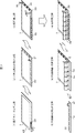
先ず、図7を用いて本発明に係る一実施形態のFPDモジュール組立装置により、FPDモジュールを組立てる工程について説明する。
図7は、FPDモジュールを組立てる工程を説明するために、組立時の様子を斜め方向から見た図である。
(1)端子クリーニング工程:表示パネル基板7の周辺端子領域を清掃する工程である。溶剤などを浸み込ませた洗浄テープ28で、端子部の異物を拭取り除去29する。その他の異物除去方法として、UVやプラズマを用いる方法が用いられる場合もある。
(2)パネル側ACF貼付工程:異方性導電フィルム(ACF)30を表示パネル基板7に貼付ける工程である。数10℃以下から100℃前後の温度で、ACFテープ30を軟化させて表示基板パネル7の部品搭載位置に仮付け31する。
(3)仮圧着工程:表示基板パネル7周辺に搭載部材(COF32やCOG(パネル基板周辺搭載IC)34など)を搭載33、35する工程である。基板パネル7に設けられた基準マークと搭載部材に設けられた基準マークを検出し位置決めをおこなって、位置ずれしない程度の加熱・加圧がおこなわれて既定の位置に搭載33、35する。
(4)本圧着工程:仮圧着工程で、基板パネル基板周辺に搭載する部品を、圧着ヘッド9により、数100℃程度の高温加熱加圧する36ことにより、導通を確保しACFを硬化させる。
(5)PCB側ACF貼付工程:異方性導電フィルム(ACF)30を周辺基板(PCB)10に貼付ける工程である。パネル側への貼付けと同様に数10℃以下から100℃前後の温度で、ACFテープ30を軟化させて周辺基板(PCB)10の接続位置に仮付け31する。
(6)PCB搭載・圧着工程:周辺回路基板10を基板パネル7周辺に圧着する工程。基板パネル7に取り付けられた搭載部材の反対側に、周辺回路基板10を位置決めし、数100℃程度の高温加熱する5ことにより、導通を確保しACFを硬化接合する。
First, the process of assembling the FPD module by the FPD module assembling apparatus according to the embodiment of the present invention will be described with reference to FIG.
FIG. 7 is a view of the assembling state seen from an oblique direction in order to explain the process of assembling the FPD module.
(1) Terminal cleaning step: This is a step of cleaning the peripheral terminal region of the display panel substrate 7. The
(2) Panel side ACF sticking step: A step of sticking the anisotropic conductive film (ACF) 30 to the display panel substrate 7. The
(3) Temporary pressure bonding process: This is a process of mounting 33 and 35 mounting members (such as
(4) Main press-bonding step: In the temporary press-bonding step, the parts mounted around the substrate panel substrate are subjected to high-temperature heating and pressurization at a high temperature of about several hundred degrees Celsius by the press-bonding head 9, thereby ensuring conduction and curing the ACF.
(5) PCB-side ACF sticking step: a step of sticking the anisotropic conductive film (ACF) 30 to the peripheral substrate (PCB) 10. The
(6) PCB mounting / crimping step: A step of crimping the
その他、各工程での検査などの工程も必要に応じておこなわれる。 In addition, processes such as inspection in each process are performed as necessary.
次に、図1および図3を用いて圧着工程をおこなう圧着装置の構造について説明する。
図1は、圧着装置の構造を示す正面図である。
図2は、シート供給部の構造を示す正面図である。
図3は、圧着装置の制御ブロック図である。
Next, the structure of the crimping apparatus that performs the crimping process will be described with reference to FIGS. 1 and 3.
FIG. 1 is a front view showing the structure of the crimping apparatus.
FIG. 2 is a front view showing the structure of the sheet supply unit.
FIG. 3 is a control block diagram of the crimping apparatus.
圧着装置は、図に示されるように、保護シートを圧着ヘッド部2に送るシート供給部1、表示パネル基板を加熱加圧する圧着ヘッド部2、保護シートと回収するシート回収部3からなる。
As shown in the figure, the crimping apparatus includes a
先ず、圧着ヘッド部2の構造について説明する。 First, the structure of the crimping head part 2 will be described.
圧着ヘッド部2は、二種類よりなるフレーム、すなわち、上下機構ベースフレーム203と圧着ヘッドベースフレーム205で外組みが構成されている。
The pressure-bonding head portion 2 is composed of two types of frames, that is, an up-and-down
上下機構ベースフレーム203上には、サーボモータ201を連結するモータ連結ブロック206、上下ガイド202が設置されている。上下ガイド202のブロック上には、上下スライダ207が設置されており、ボールネジ208、カップリング209を介することによって、サーボモータ201と上下スライダ207が直結し、上下動作がおこなわれる。
On the vertical
圧着ヘッドベースフレーム205上には、2列の横スライドガイド210、パネル受け台211が設置されている。そして、横スライドガイド210のブロック上に複数の圧着ヘッド204が設置されている。この圧着ヘッド204は、X方向に移動させることができ、Y方向には固定されている。また、圧着ヘッド204は、圧力を制御するシリンダ212と圧着刃214を加熱するヒータ213を有している。また、圧着ヘッド204の上部は上下スライダ207と横スライドガイド215を介して連結している。
Two rows of horizontal slide guides 210 and a
そして、搬送ユニット(図示せず)により表示パネル基板がパネル受け台に設置され、サーボモータ201の動作により、圧着ヘッドが下降して、搭載部材を加熱・加圧する。この際、基板パネルと圧着刃214の間に保護シートSをはさみ、圧着刃214の平坦性を保ち、はみだしたACFが圧着ヘッドの圧着面に付着しないようにする。なお、この保護シートSの素材は、シリコンゴム、ポリイミド等を使用することができる。
Then, the display panel substrate is installed on the panel cradle by a transport unit (not shown), and the operation of the
次に、シート供給部1の構造を説明する。
Next, the structure of the
シート供給部1は、図2に示されるように、供給リール102、エンド検出センサ103、供給ローラ104、送りローラ107、シート切れ検出センサ114、バッファ機構部115、ガイドローラ120a〜120hよりなる。
As shown in FIG. 2, the
供給リール102は、保護シートSを供給するリールであり、保護シートSを出し終わると供給リール102を交換する作業が必要となる。供給リール102は、供給モータ(図示せず)を回転することにより、保護シートSを供給する。
The
エンド検出センサ103は、供給リール102から供給される保護シートSの末端を検出するためのセンサである。
The
供給ローラ104は、供給モータ(図示せず)に接続されており、供給モータを回転することにより、保護シートSが供給リール102から引き出されることにより供給リール102が回転する。
The
送りローラ107は、送りモータ(図示せず)に接続されており、送りモータを回転することにより、保護シートSを移動させ、圧着ヘッド部2に供給する。供給ローラ104は、バッファ機構部115の供給リール102側にあるローラであり、送りローラ107は、バッファ機構部115の圧着ヘッド部2側にあるローラである。
The
シート切れ検出センサ114は、シート切れを検出するためのセンサである。
The sheet
バッファ機構部115は、シート供給部1において保護シートSを送る際のバッファとして機能する部分である。このバッファ機構部115については、以下で詳説する。
The
バッファ機構115は、位置が固定された固定ローラとしてのシートローラ106を複数設け、かつ、2本のリニアシャフト109上に搭載される移動部材としてのリニアブロック105上に移動ローラとしてのシートローラ110を複数設けて、保護シートSについて2山形のルーティングをさせる機構である。
The
リニアブロック105は、バッファ機構部115のシート残量により上下に可動する。
The
リニアブロック105には、センサドグ111が設置されており、第1の位置センサとしての標準位置センサ113は、リニアブロック105の位置を検出し、制御部(後述)は、リニアブロック105が第1の位置である標準位置に近づくように、供給モータを制御する。すなわち、図2においてリニアブロック105が標準位置センサ113より下にあるときには、リニアブロック105を標準位置センサ113で検出するまで上昇させるために、供給モータを止め、リニアブロック105が標準位置より上にあるときには、リニアブロック105を標準位置センサ113で検出するまで下降させるために、供給モータを回転させ、保護シートSを供給する。
A
一方、第2の位置センサとしてのシート貯蔵エンドセンサ112は、シート供給部1内において保護シートSがなくなってきたことを検出するためのセンサであり、供給リール102から保護シートSの供給がなくなり、リニアブロック105がシート貯蔵エンドセンサ112の位置まで来たときには、シート枯渇警告ランプや表示パネル(図示せず)などにより警告して、圧着ヘッド部2の圧着ヘッド204の動作を停止させる。
On the other hand, the sheet
エンド検出センサ103が保護シートSのエンドを検出しない間は、供給ローラ104は、供給モータにより稼動可能な状態にあり、エンド検出センサ103が保護シートSのエンドを検出すると供給モータは停止し、供給ローラ104による保護シートSの供給は停止する。
While the
送りローラ107の回転により保護シートSが圧着ヘッド部2に送られ、それにより、リニアブロック105は上昇する。その結果、標準位置センサ113は、センサドグ111を検出ができなくなる。一方、標準位置センサ113がセンサドグ111を感知するまで、制御部は、供給モータにより供給ローラ104を回転させ、保護シートSがバッファ機構部115に供給され、リニアブロック105は下降する。その結果、標準位置センサ113は、センサドグ111を検出する。通常はこれらが繰返しおこなわれる。
The protective sheet S is sent to the pressure-bonding head unit 2 by the rotation of the
圧着ヘッド部2に送られた保護シートSは、上述のように、圧着ヘッド部2に送られ、搭載部材と圧着刃214の保護に使われて、最後に、図1に示されるシート回収部3に送られる。ここでは、供給部1によって送られた保護シートSは、回収モータと直結した回収ローラ301の回転により、回収手段(図示せず)へ送られる。
As described above, the protective sheet S sent to the crimping head unit 2 is sent to the crimping head unit 2 and used to protect the mounting member and the crimping
エンド検出センサ103が保護シートSのエンドを検出した場合には、制御部は、シート切れ警告ランプや表示パネル(図示せず)などにより警告する。この場合には、制御部は、供給モータの回転は止めるが、圧着ヘッド部2の圧着ヘッド204の動作を停止することはない。
When the
作業者は、この警告を認識して、保護シートSの継ぎ足し作業をおこなう。すなわち、保護シートSの供給が終わった供給リール102を取り外して、供給リール102を新しいものに交換し、かつ、前の保護シートSの最後尾と取り換えた供給リール102から引き出した保護シートの最先端部を接続テープにより貼り付ける。
The worker recognizes this warning and performs the work of adding the protective sheet S. That is, the
この作業にかかる時間は、ほぼ実測で5分程度である。作業者がこの作業をせずに放置すると、上述のように、供給リール102から保護シートSの供給がなくなり、シート貯蔵エンドセンサ112がリニアブロック105の上昇を検知して、圧着装置の動作を停止することになる(現状、用いられてる装置の規模では、この時間は30分程度と見積もられる)が、それまでに、保護シートSの交換をおこなえば、装置を止めることなく、保護シートSの継ぎ足し作業をおこなうことができる。
The time required for this work is about 5 minutes in actual measurement. If the worker does not perform this work, the protective sheet S is not supplied from the
また、図2は、一例として2山形ルーティングを示しているが、山の数を増やし、シートの蓄蔵量を増やすことで、作業時間をより確保することができる。 Further, FIG. 2 shows a two-mountain routing as an example, but the working time can be further ensured by increasing the number of peaks and increasing the amount of stored sheets.
送りローラ107、回収ローラ301の駆動モータについてはシートの送り量を制御できるようサーボモータが必要であるが、供給ローラ104の駆動モータについては標準位置センサのオン・オフで制御するため、インダクションモータでもよい。
The drive motor for the
圧着装置は、図3に示すように、制御部400に各部が接続されて、その動作が制御される。
As shown in FIG. 3, each part of the crimping apparatus is connected to the
圧着刃駆動機構410は、圧着刃214を駆動する機構である。搬送機構420は、表示パネル基板を搬送する機構である。
The crimp
供給モータ430は、供給ローラ101を、供給モータ431は、供給ローラ104を、送りモータ432は、送りローラ107を、回収モータ433は、回収ローラ301を、それぞれ制御部400の指示に基づき、回転動作させる。
The supply motor 430 rotates the supply roller 101, the
また、エンド検出センサ103は、保護シートSのエンドを検出したときに、制御部400に報告する。
The
標準位置センサ113は、リニアブロック105に取り付けられたセンサドグ111が標準位置に来たときに、制御部400に報告する。
The
シート貯蔵エンドセンサ112は、リニアブロック105に取り付けられたセンサドグ111が、貯蔵されているシートがなくなると見られる位置に来たときに、制御部400に報告する。
The sheet
シート切れセンサ114は、保護シート114に、シート切れが発生したときに、制御部400に報告する。
The
シート切れ警告ランプ440は、エンド検出センサ103がシートエンドを検出したときに、制御部400の指示により、点灯する。
The out-of-
シート枯渇警告ランプ441は、シート貯蔵エンドセンサ112が、シート供給部における保護シートSがなくなってきたことを検出したときに、制御部400の指示により、点灯する。
The sheet
なお、制御はやや複雑になるが、シート切れ警告とシート枯渇警告は、表示装置を設けて、制御部400がこれに文字、アイコンを表示するなどしておこなうようにしてもよい。
Although the control is somewhat complicated, the sheet out warning and the sheet exhaustion warning may be performed by providing a display device and displaying the characters and icons on the
次に、図4を用いて圧着装置のシート送りについて説明する。
図4は、S方向におけるシート送りの様子を説明するために、圧着装置の関連する部分のみを図示した図である。
図5は、保護シートSにおける使用状態を説明するための図である。
Next, sheet feeding of the crimping apparatus will be described with reference to FIG.
FIG. 4 is a diagram illustrating only a relevant part of the crimping apparatus in order to explain the state of sheet feeding in the S direction.
FIG. 5 is a diagram for explaining a use state in the protective sheet S. FIG.
以下では、S(Source)方向(パネルの長辺)のみ説明するが、G(Gate)方向(パネルの短辺)についても同様である。 Only the S (Source) direction (the long side of the panel) will be described below, but the same applies to the G (Gate) direction (the short side of the panel).
シート供給リール102から送り出された保護シートSは、バッファ機構部115、送りローラ107を経て、ガイドローラ120f〜120hなどを経由して、ガイドローラ50aに導かれる。ガイドローラ50aは、下刃の側方に配置されている。ガイドローラ50aの回転軸は、水平方向に平行であって複数の圧着刃214が並ぶ方向に直交する方向に対して傾斜している。
The protective sheet S sent out from the
図面中央の傾斜変更部60は、二つの押さえローラ60a,60bと、テーパローラ60cから構成されている。押さえローラ60a,60bは、円柱状に形成されており、圧着刃214に対向する保護シートSが上方へ変位しないように押さえつけている。これにより、圧着刃214に対向する保護シートSは、水平方向とほぼ平行な状態を保っている。押さえローラ60a,60bの回転軸は、保護シートS、の幅方向にほぼ直交している。
The
テーパローラ60cは、押さえローラ60a,60bの上方に配置されている。このテーパローラ60cの回転軸は、圧着刃214が並ぶ方向に対して直交する方向に向いている。そして、テーパローラ60cは、圧着ヘッド部2の前方に向かうにつれて連続的に径が小さくなっている。これら押さえローラ60a,60bおよびテーパローラ60cは、ガイドローラ50aに案内された保護シートSの傾斜角度を反転させ、ガイドローラ50bに導く。
The
このように本実施形態に係る圧着装置は、圧着刃214が並ぶ方向(X方向に対して)、θ方向だけ傾斜させて、保護シートSを送る方式を採用している。
As described above, the crimping apparatus according to the present embodiment employs a method in which the protective sheet S is sent while being tilted by the θ direction in the direction in which the crimping
そのため、図5に示されように、保護シートSのほぼ全面に渡って能率的に使用することができ、一回の圧着ごとの送り量を少なくすることができる。 Therefore, as shown in FIG. 5, it can be used efficiently over almost the entire surface of the protective sheet S, and the feeding amount for each press-bonding can be reduced.
そのため、この斜め方向のシート送り方式を採用することにより、上記のシート供給部1のバッファ量を減らせることができ、シートローラ106、110の数を減らすことができる。そのため初回のセットアップのときに、シート供給部1に保護シートSをセットするときの時間を短くできるという効果がある。
Therefore, by adopting this oblique sheet feeding method, the buffer amount of the
次に、図6を用いてバッファ機構部の他の形態について説明する。
図6は、シート供給部におけるバッファ機構部の他の形態を示す図である。
Next, another form of the buffer mechanism will be described with reference to FIG.
FIG. 6 is a diagram illustrating another form of the buffer mechanism unit in the sheet supply unit.
上述のバッファ機構部115は、シートローラ間を山形ルーティングさせることにしたが、このバッファ機構部115′は、保護シートSの幅より若干広い開口部と、この開口部平面に垂直な方向の長さを有するストック部80を設けている。このストック部80は、下側に設けた吸気口81からエアを吸引することにより、保護シートSを貯蔵する。
The
吸気口81は、真空ポンプなどのエア吸引機構82に接続されている。
The
ストック部80の開口部の両端には、保護シートSをガイドするガイドローラ85、86が設けられている。
供給ローラ104からガイドローラ86に送られた保護シートSは、ストック部80の開口部を経て、ストック部80の内部に入り、再び、ストック部80の開口部およびガイドローラ85を経て、図示しない送りローラに送られる。この時、エア吸引機構82を動作させて、吸気口81からストック部80内を吸引し、図1から図3の実施形態と同様に、供給モータ、送りモータ、標準位置センサ、シート貯蔵センサ等を設けて、保護シートSの送りを制御部により制御することで、ストック部80の内部に保護シートSを貯蔵することができる。
The protective sheet S sent from the
以上、本実施形態では、本圧着工程で使用される本圧着装置を例に説明したが、PCB圧着・搭載工程で使用される圧着装置でも適応することができる。 As described above, in the present embodiment, the main pressure bonding apparatus used in the main pressure bonding process has been described as an example. However, the pressure bonding apparatus used in the PCB pressure bonding / mounting process can also be applied.
S…保護シート、0…圧着装置、1…シート供給部、2…圧着ヘッド部、3…シート回収部、
201…サーボモータ、202…上下ガイド、203…上下機構ベースフレーム、204…圧着ヘッド、205…圧着ヘッドベースフレーム、206…モータ連結ブロック、207…上下スライダ、208…ボールネジ、209…カップリング、210…横スライドガイド、211…パネル受け台、212…シリンダ、213…ヒータ、214…圧着刃、215…横スライドガイド、
102…供給リール、103…エンド検出センサ、104…供給ローラ、105…リニアブロック、106…シートローラ、107…送りローラ、109…リニアシャフト、110…シートローラ、111…センサドグ、112…シート貯蔵エンドセンサ、113…標準位置センサ、114…シート切れ検出センサ、115…バッファ機構部、120a〜120h…ガイドローラ、
301…回収ローラ、
50a,50b…ガイドローラ、60…傾斜変更部、60a,60b…押さえローラ、60c…テーパローラ、
80…ストック部、81…吸気口、82…エア吸引機構、85,86…ガイドローラ。
S ... protective sheet, 0 ... crimping device, 1 ... sheet supply unit, 2 ... crimping head unit, 3 ... sheet recovery unit,
DESCRIPTION OF
DESCRIPTION OF
301 ... Recovery roller,
50a, 50b ... guide roller, 60 ... inclination changing portion, 60a, 60b ... pressing roller, 60c ... taper roller,
80 ... Stock unit, 81 ... Intake port, 82 ... Air suction mechanism, 85, 86 ... Guide roller.
Claims (7)
制御部と、
前記保護シートを供給するシート供給部と、
前記圧着刃により表示パネル基板に搭載部材を圧着する圧着ユニット部とを備え、
前記シート供給部には、
前記保護シートが巻き回された供給リールと、
回転して前記供給リールから前記保護シートを引き出す供給ローラと、
前記保護シートを前記圧着ユニット部に送る送りローラと、
前記供給ローラと前記送りローラの間の前記保護シートの搬送経路に、前記保護シートを貯蔵するバッファ機構部とを備えることを特徴とするFPDモジュール組立装置。 In the FPD module assembling apparatus in which a protective sheet is interposed between the crimping blade and the mounting member when the mounting member is crimped to the display panel substrate.
A control unit;
A sheet supply unit for supplying the protective sheet;
A crimping unit for crimping the mounting member to the display panel substrate by the crimping blade,
In the sheet supply unit,
A supply reel on which the protective sheet is wound;
A supply roller that rotates to pull out the protective sheet from the supply reel;
A feed roller for feeding the protective sheet to the crimping unit;
An FPD module assembling apparatus comprising a buffer mechanism section for storing the protective sheet in a conveyance path of the protective sheet between the supply roller and the feed roller.
固定ローラと、
前記保護シートの搬送により移動可能な移動部材に取り付けられた移動ローラとを有し、
前記固定ローラと前記移動ローラ間で、前記保護シートをルーティングさせたことを特徴する請求項1記載のFPDモジュール組立装置。 The buffer mechanism is
A fixed roller;
A moving roller attached to a moving member movable by conveying the protective sheet,
The FPD module assembling apparatus according to claim 1, wherein the protective sheet is routed between the fixed roller and the moving roller.
前記移動部材の第1の位置を検知する第1位置センサを有し、
前記制御部は、前記供給ローラに接続された供給モータを回転させて、前記保護シートを前記バッファ機構部に供給し、前記送りローラに接続された送りモータを回転させて前記保護シートを前記バッファ機構部から前記圧着ユニット部に送り、前記第1位置センサが前記移動部材を検知するように前記供給モータおよび前記送りモータを制御することを特徴とする請求項2記載のFPDモジュール組立装置。 The buffer mechanism unit further includes:
A first position sensor for detecting a first position of the moving member;
The control unit rotates a supply motor connected to the supply roller to supply the protection sheet to the buffer mechanism unit, and rotates a feed motor connected to the feed roller to rotate the protection sheet to the buffer. 3. The FPD module assembling apparatus according to claim 2, wherein the FPD module assembly apparatus controls the supply motor and the feed motor so that the first position sensor detects the moving member.
前記移動部材の上昇の限界を検知する第2位置センサを有し、
前記第2位置センサが、前記移動部材を検知したときには、前記制御部は、前記圧着ユニットにおける圧着動作を停止することを特徴とする請求項2記載のFPDモジュール組立装置。 The buffer mechanism unit further includes:
A second position sensor for detecting a limit of the moving member ascending;
3. The FPD module assembling apparatus according to claim 2, wherein when the second position sensor detects the moving member, the control unit stops the crimping operation in the crimping unit.
前記シート供給部は、
前記供給リールから引き出される前記保護シートの終端を検知するエンド検出センサを有し、
前記エンド検出センサが前記保護シートの終端を検知したときに、前記表示装置により警告を表示することを特徴とする請求項1記載のFPDモジュール組立装置。 A display device;
The sheet supply unit
Having an end detection sensor for detecting the end of the protective sheet drawn from the supply reel;
2. The FPD module assembling apparatus according to claim 1, wherein when the end detection sensor detects the end of the protective sheet, a warning is displayed by the display device.
開口部を有し、内部に前記保護シートを貯蔵可能なストック部と、
前記ストック部内を吸引する吸引機構と、
前記ストック部の開口部における前記供給ローラ側に設けられたガイドローラと、
前記吸引機構ストック部の開口部における前記送りローラ側に設けられたガイドローラとを有し、
前記保護シートは、前記供給ローラ側に設けられたガイドローラと、前記送りローラ側に設けられたガイドローラとに掛け渡され、前記吸引機構により吸引されている前記ストック部内に引き込まれるようにしたことを特徴とする特徴する請求項1記載のFPDモジュール組立装置。 The buffer mechanism is
A stock portion having an opening and capable of storing the protective sheet therein;
A suction mechanism for sucking the inside of the stock part;
A guide roller provided on the supply roller side in the opening of the stock part;
A guide roller provided on the feed roller side in the opening of the suction mechanism stock part;
The protective sheet is stretched over a guide roller provided on the supply roller side and a guide roller provided on the feed roller side, and is drawn into the stock portion sucked by the suction mechanism. The FPD module assembling apparatus according to claim 1, characterized in that:
Priority Applications (1)
| Application Number | Priority Date | Filing Date | Title |
|---|---|---|---|
| JP2012062421A JP2013197287A (en) | 2012-03-19 | 2012-03-19 | Fpd module assembly apparatus |
Applications Claiming Priority (1)
| Application Number | Priority Date | Filing Date | Title |
|---|---|---|---|
| JP2012062421A JP2013197287A (en) | 2012-03-19 | 2012-03-19 | Fpd module assembly apparatus |
Publications (1)
| Publication Number | Publication Date |
|---|---|
| JP2013197287A true JP2013197287A (en) | 2013-09-30 |
Family
ID=49395887
Family Applications (1)
| Application Number | Title | Priority Date | Filing Date |
|---|---|---|---|
| JP2012062421A Pending JP2013197287A (en) | 2012-03-19 | 2012-03-19 | Fpd module assembly apparatus |
Country Status (1)
| Country | Link |
|---|---|
| JP (1) | JP2013197287A (en) |
Cited By (1)
| Publication number | Priority date | Publication date | Assignee | Title |
|---|---|---|---|---|
| JP2015149456A (en) * | 2014-02-10 | 2015-08-20 | パナソニックIpマネジメント株式会社 | Method of replacing protective sheets in component mounting apparatus |
-
2012
- 2012-03-19 JP JP2012062421A patent/JP2013197287A/en active Pending
Cited By (1)
| Publication number | Priority date | Publication date | Assignee | Title |
|---|---|---|---|---|
| JP2015149456A (en) * | 2014-02-10 | 2015-08-20 | パナソニックIpマネジメント株式会社 | Method of replacing protective sheets in component mounting apparatus |
Similar Documents
| Publication | Publication Date | Title |
|---|---|---|
| CN100591196C (en) | ACF sticking device and flat panel display device | |
| CN101393332B (en) | ACF pasting device and flat panel display device | |
| JP4729652B2 (en) | Component mounting apparatus and method | |
| CN101373284B (en) | ACF sticking device, manufacturing device of flat panel display, and flat panel display | |
| CN107765454B (en) | Crimping device | |
| JP4819602B2 (en) | ACF sticking device and ACF sticking method | |
| CN105939595A (en) | ACF sticking method and ACF sticking apparatus | |
| JP5315273B2 (en) | FPD module assembly equipment | |
| JP2013197287A (en) | Fpd module assembly apparatus | |
| CN101373285B (en) | ACF paste device, manufacturing device of flat panel display | |
| JP4958817B2 (en) | Electronic component mounting equipment | |
| JP5074453B2 (en) | Crimping device and replacement method of protective sheet | |
| JP5424976B2 (en) | FPD module assembly equipment | |
| JP2011142139A (en) | Acf sticking device | |
| CN105938263A (en) | ACF sticking method and ACF sticking apparatus | |
| JP5076292B2 (en) | Anisotropic conductive film pasting apparatus and method | |
| CN102683235A (en) | Assembling device and assembling method for fpd assembly | |
| JP2011033663A (en) | Panel substrate conveying device and display panel module assembling device | |
| JP2011077453A (en) | Feeding device of sheet-like member | |
| KR20080050819A (en) | Anisotropic conductive film bonding apparatus | |
| CN120854321A (en) | Packaging device | |
| JP2013088496A (en) | Pcb connection device and fpd module assembling device | |
| JP2012015218A (en) | Fpd module assembly equipment | |
| KR20100059249A (en) | Unit for separating a acf layer from a acf tape and apparatus for bonding a acf having the unit | |
| KR20070091414A (en) | Manufacturing apparatus of display device and manufacturing method of display device using same |