JP2008124156A - Organic EL material-containing solution, organic EL material thin film formation method, organic EL material thin film, organic EL element - Google Patents
Organic EL material-containing solution, organic EL material thin film formation method, organic EL material thin film, organic EL element Download PDFInfo
- Publication number
- JP2008124156A JP2008124156A JP2006304627A JP2006304627A JP2008124156A JP 2008124156 A JP2008124156 A JP 2008124156A JP 2006304627 A JP2006304627 A JP 2006304627A JP 2006304627 A JP2006304627 A JP 2006304627A JP 2008124156 A JP2008124156 A JP 2008124156A
- Authority
- JP
- Japan
- Prior art keywords
- organic
- group
- containing solution
- solvent
- substituted
- Prior art date
- Legal status (The legal status is an assumption and is not a legal conclusion. Google has not performed a legal analysis and makes no representation as to the accuracy of the status listed.)
- Withdrawn
Links
- 0 Cc1c(cccc2)c2c(-c2cc(*3C(CC*)C3)cc(C3C(CC*)C3)c2)c2ccccc12 Chemical compound Cc1c(cccc2)c2c(-c2cc(*3C(CC*)C3)cc(C3C(CC*)C3)c2)c2ccccc12 0.000 description 11
- FTAHXMZRJCZXDL-UHFFFAOYSA-N C1C=CCNC1 Chemical compound C1C=CCNC1 FTAHXMZRJCZXDL-UHFFFAOYSA-N 0.000 description 1
- JQTAAYWZZGFAOM-UHFFFAOYSA-N [AlH2]c([o]1)nnc1[AlH]O[AlH]c([o]1)nnc1[AlH2] Chemical compound [AlH2]c([o]1)nnc1[AlH]O[AlH]c([o]1)nnc1[AlH2] JQTAAYWZZGFAOM-UHFFFAOYSA-N 0.000 description 1
- ZBDZLDALJVKQKV-UHFFFAOYSA-N [AlH2]c([o]1)nnc1[AlH]c([o]1)nnc1[AlH2] Chemical compound [AlH2]c([o]1)nnc1[AlH]c([o]1)nnc1[AlH2] ZBDZLDALJVKQKV-UHFFFAOYSA-N 0.000 description 1
Classifications
-
- C—CHEMISTRY; METALLURGY
- C07—ORGANIC CHEMISTRY
- C07C—ACYCLIC OR CARBOCYCLIC COMPOUNDS
- C07C15/00—Cyclic hydrocarbons containing only six-membered aromatic rings as cyclic parts
- C07C15/20—Polycyclic condensed hydrocarbons
- C07C15/27—Polycyclic condensed hydrocarbons containing three rings
- C07C15/28—Anthracenes
-
- C—CHEMISTRY; METALLURGY
- C09—DYES; PAINTS; POLISHES; NATURAL RESINS; ADHESIVES; COMPOSITIONS NOT OTHERWISE PROVIDED FOR; APPLICATIONS OF MATERIALS NOT OTHERWISE PROVIDED FOR
- C09B—ORGANIC DYES OR CLOSELY-RELATED COMPOUNDS FOR PRODUCING DYES, e.g. PIGMENTS; MORDANTS; LAKES
- C09B1/00—Dyes with anthracene nucleus not condensed with any other ring
-
- C—CHEMISTRY; METALLURGY
- C09—DYES; PAINTS; POLISHES; NATURAL RESINS; ADHESIVES; COMPOSITIONS NOT OTHERWISE PROVIDED FOR; APPLICATIONS OF MATERIALS NOT OTHERWISE PROVIDED FOR
- C09B—ORGANIC DYES OR CLOSELY-RELATED COMPOUNDS FOR PRODUCING DYES, e.g. PIGMENTS; MORDANTS; LAKES
- C09B23/00—Methine or polymethine dyes, e.g. cyanine dyes
- C09B23/14—Styryl dyes
- C09B23/148—Stilbene dyes containing the moiety -C6H5-CH=CH-C6H5
-
- C—CHEMISTRY; METALLURGY
- C09—DYES; PAINTS; POLISHES; NATURAL RESINS; ADHESIVES; COMPOSITIONS NOT OTHERWISE PROVIDED FOR; APPLICATIONS OF MATERIALS NOT OTHERWISE PROVIDED FOR
- C09B—ORGANIC DYES OR CLOSELY-RELATED COMPOUNDS FOR PRODUCING DYES, e.g. PIGMENTS; MORDANTS; LAKES
- C09B57/00—Other synthetic dyes of known constitution
- C09B57/001—Pyrene dyes
-
- C—CHEMISTRY; METALLURGY
- C09—DYES; PAINTS; POLISHES; NATURAL RESINS; ADHESIVES; COMPOSITIONS NOT OTHERWISE PROVIDED FOR; APPLICATIONS OF MATERIALS NOT OTHERWISE PROVIDED FOR
- C09B—ORGANIC DYES OR CLOSELY-RELATED COMPOUNDS FOR PRODUCING DYES, e.g. PIGMENTS; MORDANTS; LAKES
- C09B57/00—Other synthetic dyes of known constitution
- C09B57/008—Triarylamine dyes containing no other chromophores
-
- H—ELECTRICITY
- H10—SEMICONDUCTOR DEVICES; ELECTRIC SOLID-STATE DEVICES NOT OTHERWISE PROVIDED FOR
- H10K—ORGANIC ELECTRIC SOLID-STATE DEVICES
- H10K50/00—Organic light-emitting devices
- H10K50/10—OLEDs or polymer light-emitting diodes [PLED]
- H10K50/11—OLEDs or polymer light-emitting diodes [PLED] characterised by the electroluminescent [EL] layers
- H10K50/12—OLEDs or polymer light-emitting diodes [PLED] characterised by the electroluminescent [EL] layers comprising dopants
-
- H—ELECTRICITY
- H10—SEMICONDUCTOR DEVICES; ELECTRIC SOLID-STATE DEVICES NOT OTHERWISE PROVIDED FOR
- H10K—ORGANIC ELECTRIC SOLID-STATE DEVICES
- H10K71/00—Manufacture or treatment specially adapted for the organic devices covered by this subclass
- H10K71/10—Deposition of organic active material
- H10K71/12—Deposition of organic active material using liquid deposition, e.g. spin coating
- H10K71/15—Deposition of organic active material using liquid deposition, e.g. spin coating characterised by the solvent used
-
- H—ELECTRICITY
- H10—SEMICONDUCTOR DEVICES; ELECTRIC SOLID-STATE DEVICES NOT OTHERWISE PROVIDED FOR
- H10K—ORGANIC ELECTRIC SOLID-STATE DEVICES
- H10K85/00—Organic materials used in the body or electrodes of devices covered by this subclass
- H10K85/60—Organic compounds having low molecular weight
- H10K85/615—Polycyclic condensed aromatic hydrocarbons, e.g. anthracene
- H10K85/622—Polycyclic condensed aromatic hydrocarbons, e.g. anthracene containing four rings, e.g. pyrene
-
- H—ELECTRICITY
- H10—SEMICONDUCTOR DEVICES; ELECTRIC SOLID-STATE DEVICES NOT OTHERWISE PROVIDED FOR
- H10K—ORGANIC ELECTRIC SOLID-STATE DEVICES
- H10K85/00—Organic materials used in the body or electrodes of devices covered by this subclass
- H10K85/60—Organic compounds having low molecular weight
- H10K85/615—Polycyclic condensed aromatic hydrocarbons, e.g. anthracene
- H10K85/626—Polycyclic condensed aromatic hydrocarbons, e.g. anthracene containing more than one polycyclic condensed aromatic rings, e.g. bis-anthracene
-
- H—ELECTRICITY
- H10—SEMICONDUCTOR DEVICES; ELECTRIC SOLID-STATE DEVICES NOT OTHERWISE PROVIDED FOR
- H10K—ORGANIC ELECTRIC SOLID-STATE DEVICES
- H10K85/00—Organic materials used in the body or electrodes of devices covered by this subclass
- H10K85/60—Organic compounds having low molecular weight
- H10K85/631—Amine compounds having at least two aryl rest on at least one amine-nitrogen atom, e.g. triphenylamine
-
- C—CHEMISTRY; METALLURGY
- C07—ORGANIC CHEMISTRY
- C07C—ACYCLIC OR CARBOCYCLIC COMPOUNDS
- C07C2601/00—Systems containing only non-condensed rings
- C07C2601/06—Systems containing only non-condensed rings with a five-membered ring
- C07C2601/08—Systems containing only non-condensed rings with a five-membered ring the ring being saturated
-
- C—CHEMISTRY; METALLURGY
- C07—ORGANIC CHEMISTRY
- C07C—ACYCLIC OR CARBOCYCLIC COMPOUNDS
- C07C2601/00—Systems containing only non-condensed rings
- C07C2601/12—Systems containing only non-condensed rings with a six-membered ring
- C07C2601/14—The ring being saturated
-
- C—CHEMISTRY; METALLURGY
- C07—ORGANIC CHEMISTRY
- C07C—ACYCLIC OR CARBOCYCLIC COMPOUNDS
- C07C2602/00—Systems containing two condensed rings
- C07C2602/36—Systems containing two condensed rings the rings having more than two atoms in common
- C07C2602/42—Systems containing two condensed rings the rings having more than two atoms in common the bicyclo ring system containing seven carbon atoms
-
- C—CHEMISTRY; METALLURGY
- C07—ORGANIC CHEMISTRY
- C07C—ACYCLIC OR CARBOCYCLIC COMPOUNDS
- C07C2603/00—Systems containing at least three condensed rings
- C07C2603/56—Ring systems containing bridged rings
- C07C2603/58—Ring systems containing bridged rings containing three rings
- C07C2603/70—Ring systems containing bridged rings containing three rings containing only six-membered rings
- C07C2603/74—Adamantanes
-
- H—ELECTRICITY
- H10—SEMICONDUCTOR DEVICES; ELECTRIC SOLID-STATE DEVICES NOT OTHERWISE PROVIDED FOR
- H10K—ORGANIC ELECTRIC SOLID-STATE DEVICES
- H10K85/00—Organic materials used in the body or electrodes of devices covered by this subclass
- H10K85/60—Organic compounds having low molecular weight
- H10K85/631—Amine compounds having at least two aryl rest on at least one amine-nitrogen atom, e.g. triphenylamine
- H10K85/633—Amine compounds having at least two aryl rest on at least one amine-nitrogen atom, e.g. triphenylamine comprising polycyclic condensed aromatic hydrocarbons as substituents on the nitrogen atom
Landscapes
- Chemical & Material Sciences (AREA)
- Organic Chemistry (AREA)
- Engineering & Computer Science (AREA)
- Physics & Mathematics (AREA)
- Spectroscopy & Molecular Physics (AREA)
- Materials Engineering (AREA)
- Manufacturing & Machinery (AREA)
- Optics & Photonics (AREA)
- Electroluminescent Light Sources (AREA)
Abstract
Description
本発明は、有機EL材料含有溶液、有機EL薄膜形成方法、有機EL薄膜、有機EL素子に関する。具体的には、有機EL素子を構成する有機薄膜を塗布法で形成するにあたって用いられる有機EL材料含有溶液に関する。 The present invention relates to an organic EL material-containing solution, an organic EL thin film forming method, an organic EL thin film, and an organic EL element. Specifically, the present invention relates to an organic EL material-containing solution used for forming an organic thin film constituting an organic EL element by a coating method.
有機化合物の発光を利用した有機EL素子が知られている。
この有機EL素子は、陽極と陰極との間で積層された複数の有機薄膜を有する。
有機EL材料としては、高分子材料と低分子材料が知られている。そして、合成経路の簡易さや高純度精製が可能であることから、低分子有機EL材料の開発が進められ、低分子有機EL材料のなかから効率、寿命、色純度の点で非常に優れた有機EL材料が報告され、実用化が進んでいる。
低分子有機EL材料を薄膜に成膜するにあたっては、真空蒸着法が採用され、良好な熱的安定性を持って昇華させて基板上に蒸着させることにより、高性能の有機EL素子が得られている(特許文献1、WO2004/018587)。
An organic EL element using light emission of an organic compound is known.
This organic EL element has a plurality of organic thin films laminated between an anode and a cathode.
As the organic EL material, a high molecular material and a low molecular material are known. Since the synthesis route is simple and high-purity purification is possible, the development of low-molecular-weight organic EL materials has been promoted. Among the low-molecular-weight organic EL materials, organic materials that are extremely excellent in terms of efficiency, life, and color purity. EL materials have been reported and put into practical use.
When depositing low molecular weight organic EL material on a thin film, a vacuum deposition method is adopted, and a high performance organic EL device can be obtained by sublimation with good thermal stability and vapor deposition on the substrate. (Patent Document 1, WO2004 / 018587).
しかしながら、蒸着法にあっては、高真空の設備や複雑な製造工程が必要になるという問題があった。
これに対し、有機EL材料の成膜法として塗布法が知られている。
塗布法は一般に高分子有機EL材料の成膜に用いられており、溶媒に溶解された有機EL材料を使用して有機EL材料の薄膜を形成することが行われている。この塗布法によれば、有機EL材料の薄膜を簡易に成膜することができるという利点がある。塗布法にて有機EL材料の薄膜を成膜するにあたっては、有機EL材料を溶液に溶解させる必要があるところ、高分子有機EL材料を溶媒に溶解させた塗布用組成物が一般に知られている。
溶媒としては、トルエン、キシレン、テトラリン、メシチレン、シクロへキシルベンゼン、イソプロピルビフェニルなどが用いられる。(特許文献2、3、4、WO2005/059267、特開2002-313561、特開2004-119351)
However, the vapor deposition method has a problem that high vacuum equipment and complicated manufacturing processes are required.
On the other hand, a coating method is known as a method of forming an organic EL material.
The coating method is generally used for film formation of a polymer organic EL material, and a thin film of an organic EL material is formed using an organic EL material dissolved in a solvent. This coating method has an advantage that a thin film of an organic EL material can be easily formed. In forming a thin film of an organic EL material by a coating method, it is necessary to dissolve the organic EL material in a solution, and a coating composition in which a polymer organic EL material is dissolved in a solvent is generally known. .
As the solvent, toluene, xylene, tetralin, mesitylene, cyclohexylbenzene, isopropylbiphenyl and the like are used. (Patent Documents 2, 3, 4, WO2005 / 059267, JP2002-313561, JP2004-119351)
低分子有機EL材料を塗布法で成膜するにあたり、任意の低分子有機EL材料を上記の溶媒に溶解させようとすると、低分子有機EL材料は難溶性であるという問題がある。
所定量以上(例えば0.5wt%以上)の溶解度がないと、塗布法を適用できないところ、低分子有機EL材料の溶解度は一般的に0.1wt%〜0.2wt%であり、このような低い溶解度であるため低分子有機EL材料を塗布法で成膜することができなかった。
最近では、低分子系材料でも塗布成膜ができることをみいだしているが(特開2006-190759、特許文献5)、溶解度が不十分である。また有機EL素子を実際に製造した場合に性能(発光効率、寿命)が不十分である。
In forming a low molecular organic EL material by a coating method, if an arbitrary low molecular organic EL material is dissolved in the solvent, there is a problem that the low molecular organic EL material is hardly soluble.
The application method cannot be applied without the solubility of a predetermined amount or more (for example, 0.5 wt% or more). However, the solubility of the low-molecular organic EL material is generally 0.1 wt% to 0.2 wt%, which is such a low level. Due to the solubility, a low molecular organic EL material could not be formed by a coating method.
Recently, it has been found that a coating film can be formed even with a low molecular weight material (Japanese Patent Laid-Open No. 2006-190759, Patent Document 5), but the solubility is insufficient. Moreover, when an organic EL element is actually manufactured, performance (light emission efficiency, life) is insufficient.
一方、低分子有機EL材料を溶媒に溶解させた場合、その溶液粘度が低いため、プロセス適性が低いという問題がある。
塗布法で成膜する場合、例えば、インクジェット法やノズルプリント法が知られているが、ノズルプリント法で1cp以上、インクジェット法でも1.5cp以上の粘度が必要である。
この点、高分子有機EL材料であれば、溶媒にEL材料を溶解させると粘度を大きくすることができる。
これに対し、低分子有機EL材料は、溶媒に溶解させてもそれだけでは粘度を高くすることができない。たとえば、低分子有機EL材料をトルエンやキシレンなどの溶媒に溶かしても、その溶液粘度は1cP未満である。したがって、別途粘度を高くするための増粘手段を添加する必要がある。
増粘手段としては例えばアルコール系溶液が知られているが、アルコール系溶液は低分子有機EL材料に対しては貧溶媒であるという問題がある。
このように増粘手段として貧溶媒を添加するため、ますます溶解度が低くなるという問題があった。
On the other hand, when a low-molecular organic EL material is dissolved in a solvent, there is a problem that the process suitability is low because the solution viscosity is low.
When a film is formed by a coating method, for example, an ink jet method or a nozzle print method is known, but a viscosity of 1 cp or more is required by the nozzle print method, and a viscosity of 1.5 cp or more is also required by the ink jet method.
In this regard, in the case of a polymer organic EL material, the viscosity can be increased by dissolving the EL material in a solvent.
On the other hand, the viscosity of the low-molecular organic EL material cannot be increased only by dissolving it in a solvent. For example, even when a low molecular organic EL material is dissolved in a solvent such as toluene or xylene, the solution viscosity is less than 1 cP. Therefore, it is necessary to add a thickening means for increasing the viscosity separately.
For example, an alcoholic solution is known as a thickening means, but the alcoholic solution has a problem that it is a poor solvent for a low-molecular organic EL material.
As described above, since a poor solvent is added as a thickening means, there is a problem that the solubility becomes lower.
さらに、低分子有機EL材料にあっては、時間が経過すると固体成分が析出してくるという問題があることが新たに明らかとなった。
単純に溶解度や粘度を調整した場合でも、時間が経過すると固体が析出するため塗布法で成膜すると、クラスターになって均一な薄膜が形成できず、また、例えばインクジェット法により薄膜を形成させる場合にはそのヘッドノズルが詰まるという問題が生じてしまう。
このような状態ではポットライフが極めて短く、溶液を調整してからユーザーが使用するまでの時間を極めて短くしなければならず、プロセス適応性に課題がのこる。
特開2005-259523(特許文献6)には良溶媒と貧溶媒の混合溶媒を用いたインクが開示されているが、上記の点で実用的に十分ではなかった。
Furthermore, it has been newly clarified that a low molecular organic EL material has a problem that a solid component is deposited over time.
Even if the solubility and viscosity are simply adjusted, solids will precipitate over time, so if a film is formed by the coating method, a uniform thin film cannot be formed, and for example, a thin film is formed by the inkjet method. Causes a problem that the head nozzle is clogged.
In such a state, the pot life is extremely short, and the time from the preparation of the solution to the use of the user must be extremely short, which causes a problem in process adaptability.
Japanese Patent Laid-Open No. 2005-259523 (Patent Document 6) discloses an ink using a mixed solvent of a good solvent and a poor solvent, but this is not practically sufficient in terms of the above points.
上記のような問題のため、低分子有機EL材料で、発光効率、長寿命、色純度の点で非常に優れた材料を塗布法により簡易で低コストに成膜することができず、有機EL材料の本格的実用化にとって大きな障害となっている。 Due to the above-mentioned problems, it is not possible to form a low molecular organic EL material that is very excellent in terms of light emission efficiency, long life, and color purity by a coating method with a simple and low cost. This is a major obstacle to full-scale practical application of materials.
本発明の目的は、上記問題を解消し、塗布法に適用できる有機EL材料含有溶液を提供することにある。
あわせて、本発明は、有機EL材料の薄膜形成方法、有機EL材料の薄膜、有機EL素子を提供することを目的とする。
An object of the present invention is to provide an organic EL material-containing solution that can solve the above problems and can be applied to a coating method.
In addition, an object of the present invention is to provide a method for forming a thin film of an organic EL material, a thin film of an organic EL material, and an organic EL element.
本発明の有機EL材料含有溶液は、有機EL材料と溶媒と粘度調整液とを含有する有機EL材料含有溶液であって、前記有機EL材料は、ホストとドーパントとを含み、前記ホストは、下記(1)式に示される化合物であり、前記ホストは前記溶媒に対して2wt%以上の溶解度を有することを特徴とする有機EL材料含有溶液である。
(ここで、Ar1〜Ar3は、置換または無置換の核原子数5〜50のアリール基またはヘテロアリール基、炭素数10〜30の縮合芳香族基を示す。Lは単結合、または、2価の連結基としての置換または無置換の核原子数5〜50のアリーレン基またはヘテロアリーレン基を示す。nは1〜4までの整数を示す。) (Here, Ar 1 to Ar 3 represent a substituted or unsubstituted aryl group or heteroaryl group having 5 to 50 nucleus atoms, or a condensed aromatic group having 10 to 30 carbon atoms. L is a single bond, or A substituted or unsubstituted arylene group or heteroarylene group having 5 to 50 nuclear atoms as a divalent linking group is shown, and n is an integer of 1 to 4.
この(1)式に示すように、アントラセン中心骨格に結合したフェニル基に対して置換基をメタ位につけることにより溶媒に対する溶解度を高くすることができる。また、このような材料は有機EL材料としての性能も高い。よって、塗布成膜に適した有機EL材料含有溶液とすることができる。
また、このような化合物は有機EL材料としての性能も高い。
本発明ではアントラセン中心骨格の9位、10位に置換基をつけることとしているが、従来は、可溶化させるために、1〜4位および5〜8位に置換基をつけていた。そのため、有機EL材料としての性能がでず、発光性能、寿命の点で不十分であった。
この点、本発明の化合物によれば、溶媒に対する溶解度が高く、さらに、有機EL材料としての性能も高い。
また、このようにホスト材料の溶解度を十分に高くできるので、塗布プロセスに必要とされる粘度の調整を行うための粘度調整用の溶液を加えることができる。このような粘度調整液は貧溶媒であることが多いが、このような貧溶媒であってもホストの溶解度が十分に高いので、必要な溶解量を確保したうえで粘度調整用の溶液を加えることができる。
したがって、塗布成膜に適した有機EL材料含有溶液とすることができる。
As shown in the formula (1), the solubility in a solvent can be increased by attaching a substituent to the meta position with respect to the phenyl group bonded to the anthracene central skeleton. Moreover, such a material has high performance as an organic EL material. Therefore, an organic EL material-containing solution suitable for coating film formation can be obtained.
Moreover, such a compound has high performance as an organic EL material.
In the present invention, substituents are added to the 9th and 10th positions of the anthracene central skeleton, but conventionally, substituents were added to the 1st to 4th positions and the 5th to 8th positions for solubilization. Therefore, the performance as an organic EL material was not achieved, and the light emission performance and the life were insufficient.
In this respect, according to the compound of the present invention, the solubility in a solvent is high, and the performance as an organic EL material is also high.
Further, since the solubility of the host material can be sufficiently increased as described above, a viscosity adjusting solution for adjusting the viscosity required for the coating process can be added. Such a viscosity adjusting solution is often a poor solvent, but even with such a poor solvent, the solubility of the host is sufficiently high, so a viscosity adjusting solution is added after ensuring the necessary amount of dissolution. be able to.
Therefore, an organic EL material-containing solution suitable for coating film formation can be obtained.
ここで、ホスト材料とドーパント材料について説明する。
有機EL素子は、例えば、正孔注入層/正孔輸送層/発光層/電子輸送層/電子注入層、等の各機能を有する層の積層によって構成される。そして、発光層はホスト材料とドーパント材料とで構成され、ホスト材料からドーパント材料にエネルギー移動等が生じ、ドーパント材料が発光機能を担う。
ホスト材料に対してドーパント材料が添加(ドープ)されており、その比はドーパント材料/ホスト材料は0.01〜20wt%とすることが一例として挙げられる。ホスト材料は、例えば30nm〜100nmの発光層の大部分(例えば80%以上)を構成することになるので、塗布プロセスにて発光層を成膜するには、有機EL材料含有溶液に所定量のホスト材料が溶解していなければならない。
この点、本発明によれば、塗布成膜に適した有機EL材料含有溶液とすることができる。
Here, the host material and the dopant material will be described.
An organic EL element is comprised by lamination | stacking of the layer which has each function, such as a hole injection layer / hole transport layer / light emitting layer / electron transport layer / electron injection layer, for example. The light emitting layer is composed of a host material and a dopant material. Energy transfer or the like occurs from the host material to the dopant material, and the dopant material has a light emitting function.
As an example, the dopant material is added (doped) to the host material, and the ratio of the dopant material / host material is 0.01 to 20 wt%. Since the host material constitutes most of the light emitting layer of, for example, 30 nm to 100 nm (for example, 80% or more), a predetermined amount of the organic EL material-containing solution is used to form the light emitting layer in the coating process. The host material must be dissolved.
In this regard, according to the present invention, an organic EL material-containing solution suitable for coating film formation can be obtained.
なお、Lは単結合、または、2価の連結基であり、置換または無置換の核原子数5〜50のアリーレン基またはヘテロアリーレン基であり、好ましくは炭素数10〜30の縮合芳香族基である。 L is a single bond or a divalent linking group, and is a substituted or unsubstituted arylene group or heteroarylene group having 5 to 50 nucleus atoms, preferably a condensed aromatic group having 10 to 30 carbon atoms. It is.
本発明では、前記Ar1〜Ar3は、置換または無置換の核原子数5〜50のアリール基であることが好ましい。 In the present invention, Ar 1 to Ar 3 are preferably a substituted or unsubstituted aryl group having 5 to 50 nuclear atoms.
本発明では、前記Ar1〜Ar3は、置換または無置換のフェニル基またはナフチル基であることが好ましい。 In the present invention, the Ar 1 to Ar 3 are preferably a substituted or unsubstituted phenyl group or naphthyl group.
Ar1からAr3について、フェニル基やナフチル基とすれば、ホスト材料としての性能、寿命ともに向上させることができる。したがって、可溶性およびEL性能の両面で優れたものとできる。 If Ar 1 to Ar 3 are a phenyl group or a naphthyl group, both performance and life as a host material can be improved. Therefore, it can be excellent in both solubility and EL performance.
本発明では、前記化合物に代えて下記(2)式に示される化合物をホストとすることを特徴とする有機EL材料含有溶液。
(ここで、Ar1は置換または無置換の核原子数5〜50のアリール基またはヘテロアリール基、を示す。Lは単結合、または、2価の連結基としての置換または無置換の核原子数5〜50のアリーレン基またはヘテロアリーレン基、炭素数10〜30の縮合芳香族基を示す。nは1〜4までの整数を示す。 (Wherein Ar 1 represents a substituted or unsubstituted aryl group or heteroaryl group having 5 to 50 nuclear atoms. L represents a single bond or a substituted or unsubstituted nuclear atom as a divalent linking group. An arylene group or heteroarylene group having a number of 5 to 50 and a condensed aromatic group having a carbon number of 10 to 30. n represents an integer of 1 to 4.
前記(2)式に示すように、アントラセン中心骨格にフェニル基を挟んでパラ位でナフチル基を繋ぐことにより溶解度を高くすることができる。
また、このような化合物は有機EL材料としての性能も高い。
したがって、塗布成膜に適した有機EL材料含有溶液とすることができる。
As shown in the formula (2), the solubility can be increased by connecting a naphthyl group at the para position with a phenyl group sandwiched between the anthracene central skeleton.
Moreover, such a compound has high performance as an organic EL material.
Therefore, an organic EL material-containing solution suitable for coating film formation can be obtained.
本発明では、前記Ar1は置換または無置換の核原子数5〜50のアリール基であることが好ましい。 In the present invention, Ar 1 is preferably a substituted or unsubstituted aryl group having 5 to 50 nucleus atoms.
本発明では、前記Ar1は、置換または無置換のフェニル基またはナフチル基であることが好ましい。 In the present invention, the Ar 1 is preferably a substituted or unsubstituted phenyl group or naphthyl group.
可溶化については上記式の右側の構造で達成することとし、上記式において左側については有機EL材料としての性能を高める置換基を選択することができる。例えば、フェニル基やナフチル基とすれば、ホスト材料としての性能、寿命ともに向上させることができる。
したがって、可溶性およびEL性能の両面で優れたものとできる。
Solubilization is achieved by the structure on the right side of the above formula, and a substituent that enhances the performance as the organic EL material can be selected for the left side in the above formula. For example, when a phenyl group or a naphthyl group is used, both performance and life as a host material can be improved.
Therefore, it can be excellent in both solubility and EL performance.
本発明では、前記nは、1または2であることが好ましい。 In the present invention, the n is preferably 1 or 2.
nが大きすぎる場合、有機EL材料としての性能が十分に発現されないところ、nを1または2とすることにより、発光性能および寿命の点で優れた材料とできる。そして、このような材料は溶解性も高いので、塗布成膜用に好適な有機EL材料含有溶液とすることができる。 When n is too large, performance as an organic EL material is not sufficiently exhibited. However, by setting n to 1 or 2, a material excellent in light emission performance and lifetime can be obtained. Since such a material has high solubility, an organic EL material-containing solution suitable for coating film formation can be obtained.
本発明では、前記ドーパントは、下記(3)式に示されるスチリルアミン誘導体であり、かつ、炭素数2〜6で直鎖、または分岐構造を有するアルキル基または炭素数5〜10のシクロアルキル基である置換基を有し、前記ドーパント材料は前記溶媒に対して0.5wt%以上の溶解度を有することが好ましい。 In the present invention, the dopant is a styrylamine derivative represented by the following formula (3), and is an alkyl group having 2 to 6 carbon atoms or a linear or branched structure, or a cycloalkyl group having 5 to 10 carbon atoms. It is preferable that the dopant material has a solubility of 0.5 wt% or more with respect to the solvent.
(ここで、Ar4〜Ar6のうち少なくとも一つはスチリル基を含む。また、好ましくは、Ar4は、フェニル、ビフェニル、テルフェニル、スチルベン、ジスチリルアリールから選ばれる基であり、Ar5及びAr6は、それぞれ水素原子又は炭素数が6〜20の芳香族基であり、p’は、1〜4の整数である。) (Here, at least one of Ar 4 to Ar 6 contains a styryl group. Preferably, Ar 4 is a group selected from phenyl, biphenyl, terphenyl, stilbene and distyrylaryl, and Ar 5 And Ar 6 are each a hydrogen atom or an aromatic group having 6 to 20 carbon atoms, and p ′ is an integer of 1 to 4.)
ここで、炭素数が6〜20の芳香族基としては、フェニル基、ナフチル基、アントラセニル基、フェナントリル基、テルフェニル基等が好ましい。 Here, as the aromatic group having 6 to 20 carbon atoms, a phenyl group, a naphthyl group, an anthracenyl group, a phenanthryl group, a terphenyl group, and the like are preferable.
本発明では、前記(3)式に示されるスチリルアミン誘導体に代えて、下記(4)式に示されるアリールアミンの置換誘導体であって炭素数2〜6で直鎖、または分岐構造を有するアルキル基または炭素数5〜10のシクロアルキル基を置換基に有する化合物を前記ドーパント材料とすることが好ましい。 In the present invention, instead of the styrylamine derivative represented by the formula (3), a substituted derivative of an arylamine represented by the following formula (4), which has 2 to 6 carbon atoms and has a linear or branched structure Preferably, the dopant material is a group or a compound having a cycloalkyl group having 5 to 10 carbon atoms as a substituent.
(ここで、Ar7〜Ar9は置換または無置換の核炭素数5〜40のアリール基である。q’は、1〜4の整数である。) (Here, Ar 7 to Ar 9 are substituted or unsubstituted aryl groups having 5 to 40 nuclear carbon atoms. Q ′ is an integer of 1 to 4.)
ここで、核原子数が5〜40のアリール基としては、フェニル、ナフチル、アントラセニル、フェナントリル、ピレニル、クリセニル、コロニル、ビフェニル、テルフェニル、ピローリル、フラニル、チオフェニル、ベンゾチオフェニル、オキサジアゾリル、ジフェニルアントラセニル、インドリル、カルバゾリル、ピリジル、ベンゾキノリル、フルオレニル、フルオランテニル、アセナフトフルオランテニル、スチルベン、又は、下記一般式(A)、(B)で示される基等が好ましい。
一般式(A)においてrは1〜3の整数である。
Here, the aryl group having 5 to 40 nucleus atoms includes phenyl, naphthyl, anthracenyl, phenanthryl, pyrenyl, chrysenyl, coronyl, biphenyl, terphenyl, pyrrolyl, furanyl, thiophenyl, benzothiophenyl, oxadiazolyl, diphenylanthracene. Nyl, indolyl, carbazolyl, pyridyl, benzoquinolyl, fluorenyl, fluoranthenyl, acenaphthofluoranthenyl, stilbene, or groups represented by the following general formulas (A) and (B) are preferable.
In general formula (A), r is an integer of 1-3.
なお、核原子数が5〜40のアリール基は、さらに置換基により置換されていてもよく、好ましい置換基としては、炭素数2〜6のアルキル基(エチル基、メチル基、イソプロピル基、n−プロピル基、s−ブチル基、t−ブチル基、ペンチル基、ヘキシル基、シクロペンチル基、シクロヘキシル基等)が挙げられる。 The aryl group having 5 to 40 nucleus atoms may be further substituted with a substituent. Preferred substituents include alkyl groups having 2 to 6 carbon atoms (ethyl group, methyl group, isopropyl group, n -Propyl group, s-butyl group, t-butyl group, pentyl group, hexyl group, cyclopentyl group, cyclohexyl group, etc.).
このような組成の溶液において、低分子有機EL材料にあっては溶媒に対して溶解度が稼げないところ、置換基として炭素数2〜6の直鎖または分岐構造のアルキル基、炭素数5〜10のシクロアルキル基を有することにより溶解度が所定量以上であり、低分子有機EL材料のなかでも溶解度を大きくすることができる。
そして、このように十分な溶解度を有する材料を溶質とするので、この材料を溶質として溶解させたうえでさらに粘度調整用の増粘剤として粘度調整液を添加することができる。
これにより、例えば1cp以上の粘度を有し、0.5wt%以上の溶解量を有する有機EL材料含有溶液とすることができる。
一般に低分子有機EL材料は難溶性であり、また、溶解しても粘度が大きくならないため、低分子有機EL材料を溶解させ、かつ、十分な粘度を持つための溶媒を選択することは困難である。
この点、低分子有機EL材料を溶解させるための溶媒と、粘度を調製するための粘度調整液とを別々に選択することにより、十分な溶解度と十分な粘度を両立させることができる。
In a solution having such a composition, in a low molecular organic EL material, solubility in a solvent cannot be obtained. However, a linear or branched alkyl group having 2 to 6 carbon atoms as a substituent, or 5 to 10 carbon atoms. By having the cycloalkyl group, the solubility is not less than a predetermined amount, and the solubility can be increased among the low-molecular organic EL materials.
And since the material which has sufficient solubility in this way is used as a solute, after dissolving this material as a solute, a viscosity adjusting liquid can be further added as a thickener for viscosity adjustment.
Thereby, it can be set as the organic EL material containing solution which has a viscosity of 1 cp or more, for example, and has a dissolution amount of 0.5 wt% or more.
In general, low-molecular organic EL materials are hardly soluble, and since the viscosity does not increase even when dissolved, it is difficult to select a solvent for dissolving the low-molecular organic EL material and having sufficient viscosity. is there.
In this respect, by selecting separately the solvent for dissolving the low molecular organic EL material and the viscosity adjusting liquid for adjusting the viscosity, it is possible to achieve both sufficient solubility and sufficient viscosity.
ここで、低分子有機EL材料は一般に難溶性であるが、単純に塗布用に必要な溶解度程度に溶媒に溶解する材料を選ぶだけでは不十分である。
低分子ELにあっては、高分子EL材料と異なり、溶液に粘度がないため、増粘手段が必要となる。
その増粘手段としては、増粘材となる粘度調整液を添加剤として加えるが、粘度調整液は一般には低分子有機EL材料に対して貧溶媒である。
よって、粘度を十分に持つ程度に粘度調整液を加えたうえで、塗布用に十分な溶解量を有する必要があるため、溶媒に対する溶解度としては単に塗布用溶液に必要とされる溶解度よりも大きい値が必要となる。
この点、本発明では、実験に基づいて、溶媒に可溶な化合物のなかでも所定値以上の溶解度を示すものを特に選択した。すなわち、特定の化合物を選定することにより溶解度が所定量以上であるものとしている。これにより、粘度調製を十分に行ったうえでも、低分子材料が均一に溶解している有機EL材料含有溶液とすることができ、塗布用に好適である。
Here, the low-molecular organic EL material is generally poorly soluble, but it is not sufficient to simply select a material that dissolves in a solvent to the extent necessary for coating.
In the low molecular EL, unlike the polymer EL material, since the solution has no viscosity, a thickening means is required.
As the thickening means, a viscosity adjusting liquid serving as a thickener is added as an additive, but the viscosity adjusting liquid is generally a poor solvent for the low molecular organic EL material.
Therefore, since it is necessary to add a viscosity adjusting liquid to an extent having sufficient viscosity and to have a sufficient amount of dissolution for coating, the solubility in a solvent is simply larger than that required for the coating solution. A value is required.
In this regard, in the present invention, based on experiments, a compound that exhibits a solubility equal to or higher than a predetermined value is selected from among compounds soluble in a solvent. That is, the solubility is set to a predetermined amount or more by selecting a specific compound. Thereby, even if viscosity adjustment is fully performed, it can be set as the organic EL material containing solution in which the low molecular material is melt | dissolving uniformly, and is suitable for application | coating.
さらに、低分子有機EL材料を溶媒に溶解させた場合でも、時間が経過すると比較的短時間(例えば、数時間〜数日)で析出してくるという問題が生じる。高分子の有機EL材料であれば溶媒に溶解したのち再び析出してくることは通常ではないところ、低分子有機EL材料を塗布用として扱う場合の新たな課題である。
この点、本発明では、実験により、溶解後に時間の経過をおって析出物の有無を確認し、溶媒に所定量以上可溶であって、さらに、析出までの時間が所定時間以上であるものを選択することとし、それらは特定の構造を有するホスト材料と特定の置換基を有するドーパント材料としている。
これにより、有機EL材料含有溶液のポットライフを十分に長くし、有機EL材料含有溶液を実用に資するものとできる。
Furthermore, even when the low-molecular organic EL material is dissolved in a solvent, there arises a problem that it precipitates in a relatively short time (for example, several hours to several days) as time elapses. In the case of a high-molecular organic EL material, it is not normal that it is dissolved in a solvent and then precipitated again, but this is a new problem when a low-molecular organic EL material is used for coating.
In this regard, in the present invention, the presence or absence of precipitates is confirmed over time after dissolution by experiment, and is soluble in a solvent in a predetermined amount or more, and further, the time until precipitation is not less than a predetermined time. These are a host material having a specific structure and a dopant material having a specific substituent.
Thereby, the pot life of the organic EL material-containing solution can be made sufficiently long, and the organic EL material-containing solution can be practically used.
なお、炭素数2〜6で分岐構造を有するアルキル基または炭素数5〜10のシクロアルキル基を置換基に有する」とは、分子構造の末端にこのような置換基を有することをいい、つまり、Ar4〜Ar9のうち分子の末端にくるものが前記の置換基を有することをいう。 The term “having an alkyl group having 2 to 6 carbon atoms and a branched structure or a cycloalkyl group having 5 to 10 carbon atoms as a substituent” means having such a substituent at the end of the molecular structure. , Ar 4 to Ar 9 have the above substituents at the end of the molecule.
本発明では、前記溶媒は、芳香族系溶媒、ハロゲン系溶媒およびエーテル系溶媒のうちから選択され、前記粘度調整液は、アルコール系溶液、ケトン系溶液、パラフィン系溶液および炭素数4以上のアルキル置換芳香族系溶液のうちから選択されることが好ましい。 In the present invention, the solvent is selected from an aromatic solvent, a halogen solvent, and an ether solvent, and the viscosity adjusting liquid is an alcohol solution, a ketone solution, a paraffin solution, or an alkyl having 4 or more carbon atoms. It is preferably selected from substituted aromatic solutions.
このように溶媒として、芳香族系溶媒、ハロゲン系溶媒およびエーテル系溶媒のうちから選択すれば低分子有機EL材料を必要量(例えば、2wt%)以上溶解させることができる。
また、粘度調整液としてアルコール系溶液、ケトン系溶液およびパラフィン系溶液のうちから選択すれば粘度を増加させて各種の塗布手段(インクジェット、ノズルプリンタ、スピンコート)に適した粘度に調整することができる。
なお、溶媒は、芳香族系溶媒、ハロゲン系溶媒およびエーテル系溶媒のうちから選択される少なくとも一つであり、2つ以上を混合してもよいことはもちろんである。
同様に、粘度調整液も、アルコール系溶液、ケトン系溶液およびパラフィン系溶液、アルキル置換芳香族系溶液、炭素数4以上のアルキル置換芳香族系溶液のうちから選択される少なくとも一つであり、2つ以上を混合してもよいことはもちろんである。
As described above, when the solvent is selected from an aromatic solvent, a halogen solvent, and an ether solvent, the low molecular organic EL material can be dissolved in a necessary amount (for example, 2 wt%) or more.
In addition, if the viscosity adjusting liquid is selected from alcohol-based solutions, ketone-based solutions, and paraffin-based solutions, the viscosity can be increased and adjusted to a viscosity suitable for various application means (inkjet, nozzle printer, spin coating). it can.
The solvent is at least one selected from an aromatic solvent, a halogen solvent, and an ether solvent, and of course, two or more may be mixed.
Similarly, the viscosity adjusting liquid is also at least one selected from an alcohol-based solution, a ketone-based solution, a paraffin-based solution, an alkyl-substituted aromatic solution, and an alkyl-substituted aromatic solution having 4 or more carbon atoms, Of course, two or more may be mixed.
なお、炭素数4以上のアルキル置換芳香族系溶液とは、すなわち、芳香族であって炭素数4以上のアルキル置換基を有するものをいう。アルキル置換基の炭素数の上限については特に定めるものではないが、例えば50程度を上限にすることが一例として挙げられる。 The alkyl-substituted aromatic solution having 4 or more carbon atoms means an aromatic solution having an alkyl substituent having 4 or more carbon atoms. The upper limit of the number of carbon atoms of the alkyl substituent is not particularly defined, but for example, an upper limit of about 50 is an example.
本発明では、前記溶媒は前記芳香族系溶媒とし、前記粘度調整液は前記アルコール系溶液または炭素数4以上のアルキル置換芳香族系溶液とすることが好ましい。 In the present invention, the solvent is preferably the aromatic solvent, and the viscosity adjusting liquid is preferably the alcohol solution or an alkyl-substituted aromatic solution having 4 or more carbon atoms.
ここで、粘度調整液としてアルコール系溶液とするとアルコール系は水を吸いやすいことから溶液の保存管理に注意を要するところ、粘度調整液として炭素数4以上のアルキル置換芳香族系溶液とすると疎水性であるので保管が簡便であるという利点がある。
また、炭素数4以上のアルキル置換芳香族系溶液であれば、アルキル基の構造を変化させる(例えばアルキル鎖を長くする)ことにより粘度調整が可能であるという利点がある。
また、アルコール系溶液は粘度が高いので、高い溶液粘度を必要とする成膜プロセス(例えばインクジェット法)に適した溶液を調整する際に好適である。
また、アルコール系溶液の方が沸点が高いという点でも塗布プロセス適性を調整するのに好適である。
Here, if an alcohol-based solution is used as a viscosity adjusting solution, the alcohol-based solution easily absorbs water, so care must be taken for storage management of the solution. Therefore, there is an advantage that storage is simple.
Further, an alkyl-substituted aromatic solution having 4 or more carbon atoms has an advantage that the viscosity can be adjusted by changing the structure of the alkyl group (for example, lengthening the alkyl chain).
In addition, since the alcohol-based solution has a high viscosity, it is suitable for preparing a solution suitable for a film forming process (for example, an ink jet method) that requires a high solution viscosity.
Further, the alcohol-based solution is also suitable for adjusting the suitability of the coating process in that the boiling point is higher.
なお、粘度調整液の種類や混合量等は、各種の成膜プロセスに必要な粘度に応じて適宜選択されうる。 In addition, the kind, mixing amount, etc. of a viscosity adjustment liquid can be suitably selected according to the viscosity required for various film-forming processes.
本発明の有機EL材料の薄膜形成方法は、前記有機EL材料含有溶液を被成膜領域に滴下する滴下工程と、前記滴下工程にて滴下された有機EL材料含有溶液から前記溶媒を蒸発させて前記有機EL材料を成膜する成膜工程と、を備えることを特徴とする。 The organic EL material thin film forming method of the present invention includes a dropping step of dropping the organic EL material-containing solution onto a film formation region, and evaporating the solvent from the organic EL material-containing solution dropped in the dropping step. A film forming step for forming the organic EL material.
本発明の有機EL材料の薄膜は、前記有機EL材料の薄膜形成方法により形成されたことを特徴とする。 The organic EL material thin film of the present invention is formed by the organic EL material thin film forming method.
本発明の有機EL素子は、前記有機EL材料の薄膜を含んだことを特徴とする。 The organic EL device of the present invention includes a thin film of the organic EL material.
なお、本発明の有機EL材料含有溶液をそのまま塗布用の溶液として利用してもよく、この有機EL材料含有溶液に対してその他の添加剤を添加して塗布手段に応じた粘度や沸点、濃度に調整してもよいことはもちろんである。 In addition, you may utilize the organic EL material containing solution of this invention as a solution for application | coating as it is, the viscosity, boiling point, density | concentration according to the application | coating means by adding another additive with respect to this organic EL material containing solution Of course, it may be adjusted.
以下、本発明について具体的に説明する。
本発明の有機EL材料含有溶液は、有機EL材料が溶媒に溶解されたものである。
有機EL材料含有溶液は、ホストとドーパントとを含む。
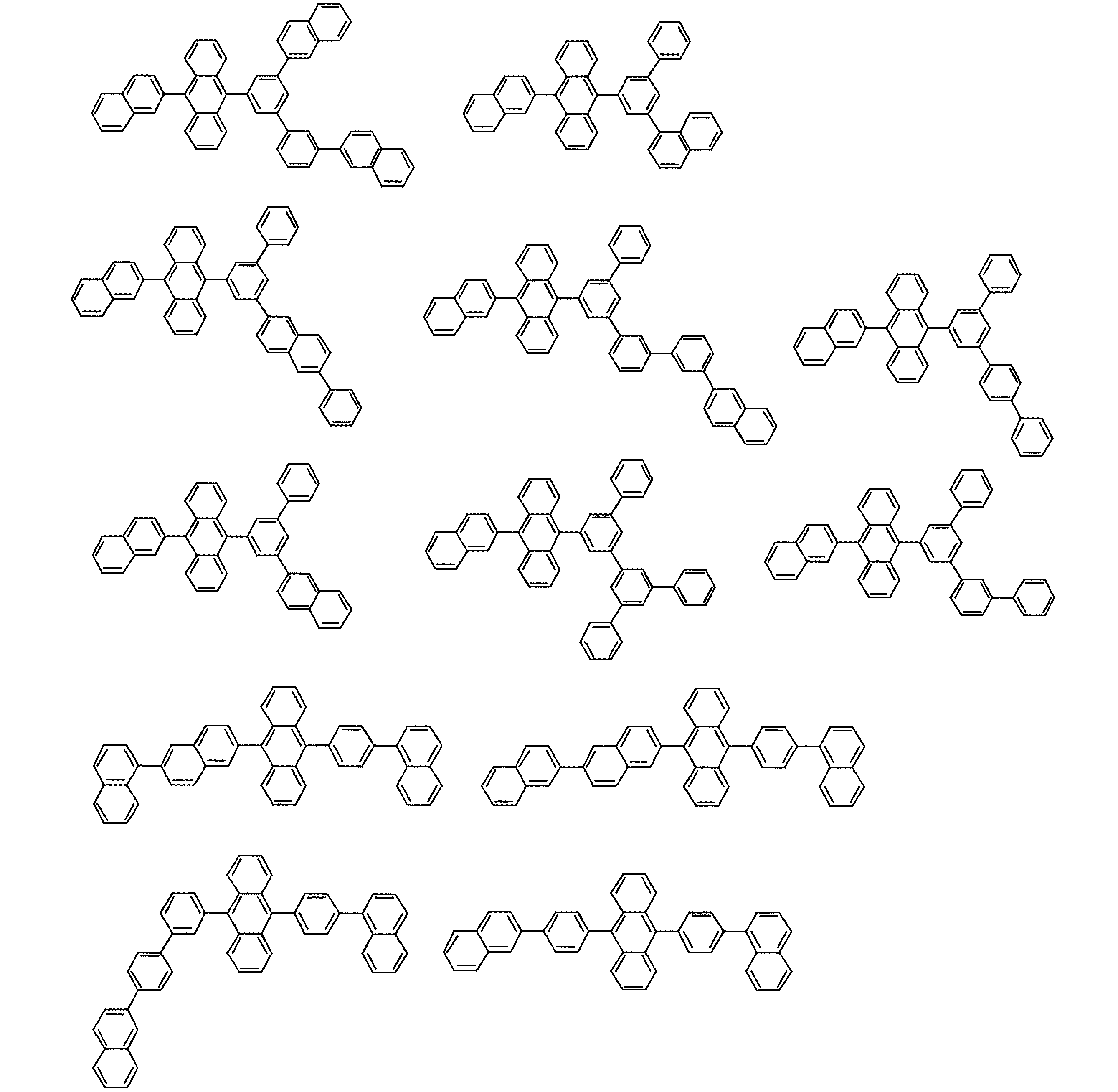
ホストとしては、例えば、下記に示すアントラセン化合物があげられる。
Hereinafter, the present invention will be specifically described.
The organic EL material-containing solution of the present invention is obtained by dissolving an organic EL material in a solvent.
The organic EL material-containing solution contains a host and a dopant.
Examples of the host include the following anthracene compounds.
ドーパント材料としては、例えば下記に示す縮合芳香族アミンまたはスチリルアミンが挙げられる。 Examples of the dopant material include condensed aromatic amines and styrylamines shown below.
溶媒は、溶媒と粘度調整液との混合溶液である。溶媒としては、芳香族系溶媒、ハロゲン系溶媒およびエーテル系溶媒のうちから選択される。粘度調整液は、アルコール系溶液、ケトン系溶液、パラフィン系溶液および炭素数4以上のアルキル置換芳香族系溶液のうちから選択される。 The solvent is a mixed solution of a solvent and a viscosity adjusting liquid. The solvent is selected from an aromatic solvent, a halogen solvent, and an ether solvent. The viscosity adjusting liquid is selected from an alcohol-based solution, a ketone-based solution, a paraffin-based solution, and an alkyl-substituted aromatic solution having 4 or more carbon atoms.
好ましくは、溶媒は芳香族系溶媒であり、粘度調整液はアルコール系溶液または炭素数4以上のアルキル置換芳香族系溶液である。 Preferably, the solvent is an aromatic solvent, and the viscosity adjusting liquid is an alcohol-based solution or an alkyl-substituted aromatic solution having 4 or more carbon atoms.
更に好ましくは、溶媒である芳香族系溶媒はトルエン、キシレン、メシチレン、およびクロルベンゼンである。
また、粘度調整液であるアルコール系溶液は炭素数1〜20の直鎖または分岐アルコールであり、メタノール、エタノール、プロパノール、ブタノール、ペンタノール、ヘキサノール、ヘプタノール、オクタノール、ノナノール、デカノール等やベンジルアルコール誘導体、ヒドロキアルキルベンゼン誘導体。
炭素数4以上のアルキル置換芳香族系溶液としては、炭素数4以上のアルキルベンゼン誘導体が挙げられ、直鎖または分岐のブチルベンゼン、ドデシルベンゼン、テトラリン、シクロヘキシルベンゼンなどが挙げられる。
More preferably, the aromatic solvent as the solvent is toluene, xylene, mesitylene, and chlorobenzene.
In addition, the alcoholic solution that is a viscosity adjusting liquid is a linear or branched alcohol having 1 to 20 carbon atoms, such as methanol, ethanol, propanol, butanol, pentanol, hexanol, heptanol, octanol, nonanol, decanol, and benzyl alcohol derivatives. Hydroxyalkylbenzene derivatives.
Examples of the alkyl-substituted aromatic solution having 4 or more carbon atoms include alkylbenzene derivatives having 4 or more carbon atoms, such as linear or branched butylbenzene, dodecylbenzene, tetralin, cyclohexylbenzene, and the like.
なお、ハロゲン系炭化水素系溶媒(ハロゲン系溶媒)としては、ジクロロメタン、ジクロロエタン、クロロホルム、四塩化炭素、テトラクロロエタン、トリクロロエタン、クロロベンゼン、ジクロロベンゼン、クロロトルエンが例として挙げられる。
エーテル系溶媒としては、ジブチルエーテル、テトラヒドロフラン、ジオキサン、アニソールが例として挙げられる。
Examples of halogen-based hydrocarbon solvents (halogen-based solvents) include dichloromethane, dichloroethane, chloroform, carbon tetrachloride, tetrachloroethane, trichloroethane, chlorobenzene, dichlorobenzene, and chlorotoluene.
Examples of ether solvents include dibutyl ether, tetrahydrofuran, dioxane, and anisole.
本発明の実施例、比較例について説明する。 Examples of the present invention and comparative examples will be described.
(溶解度評価)
溶解度評価について説明する。
(Solubility evaluation)
The solubility evaluation will be described.
(溶解度評価1)
まず、溶解度評価1としてホスト材料として用いられる化合物の溶解度評価の例を示す。
化合物H1から化合物H9について溶解度評価を行った。
溶解度評価1の方法としては次のようにした。
すなわち、化合物100mgをサンプル瓶にとり、化合物が溶解するまで溶媒であるトルエンを加え、加えたトルエンの量から、トルエンに対する溶解度を計算した。
溶解度評価1の対象とした化合物は下に示す化合物H1から化合物H9である。
溶解度評価1の結果を表1に示す。
(Solubility evaluation 1)
First, an example of solubility evaluation of a compound used as a host material as solubility evaluation 1 is shown.
Solubility evaluation was performed about the compound H1 to the compound H9.
The method for solubility evaluation 1 was as follows.
That is, 100 mg of the compound was placed in a sample bottle, toluene as a solvent was added until the compound was dissolved, and the solubility in toluene was calculated from the amount of added toluene.
Compounds targeted for solubility evaluation 1 are the compounds H1 to H9 shown below.
The results of solubility evaluation 1 are shown in Table 1.
化合物H1から化合物H5は、トルエンに対して高い溶解度を示した。
その一方、化合物H6〜H8は0.5wt%以下の低い溶解度であった。
0.5wt%以下の溶解度では湿式成膜における膜厚調整が困難となるため、化合物H6、H7、H8は湿式成膜用としては不適である。
一方、化合物H9は湿式成膜における膜厚調整が可能な溶解度を有している。
ここで、溶解度が0.5wt%以上の化合物は混合溶液インクにおける評価を行うこととする。
Compounds H1 to H5 showed high solubility in toluene.
On the other hand, the compounds H6 to H8 had a low solubility of 0.5 wt% or less.
If the solubility is 0.5 wt% or less, it is difficult to adjust the film thickness in the wet film formation, so the compounds H6, H7, and H8 are not suitable for wet film formation.
On the other hand, the compound H9 has a solubility capable of adjusting the film thickness in wet film formation.
Here, a compound having a solubility of 0.5 wt% or more is evaluated in the mixed solution ink.
溶解度評価1により、アントラセン化合物の溶解性を高くするには特定の置換基が必要であることがわかった。
化合物H1から化合物H4の結果から、アントラセン中心骨格にフェニル基を挟んでパラ位でナフチル基を繋げば溶解度を高くすることができ、(2)式により溶解度が高くなることが示された。
また、化合物H5の結果から、アントラセン中心骨格に結合したフェニル基に対して置換基が2つつくことが好ましいことが示された。
ここで、さらに、前記フェニル基につく置換基は2つともメタ位につくことが好ましく(1)式により溶解度が高くなることが示された。
From the solubility evaluation 1, it was found that a specific substituent is necessary to increase the solubility of the anthracene compound.
From the results of Compound H1 to Compound H4, it was shown that the solubility can be increased by linking the naphthyl group at the para position with the phenyl group sandwiched between the anthracene central skeleton, and the solubility is increased by the formula (2).
In addition, from the results of Compound H5, it was shown that it is preferable that two substituents are attached to the phenyl group bonded to the anthracene central skeleton.
Here, it is further preferable that both of the substituents attached to the phenyl group are attached to the meta position, and the solubility is increased by the formula (1).
(溶解度評価2)
次に、溶解度評価2として、ドーパント材料として用いられる化合物の溶解度評価の例を示す。
対象とした化合物は前述のドーパントの化合物例と下記化合物D1から化合物D4である。
下記化合物を用いた以外は前記溶解度評価1と同様に溶解度を計算した。
結果を表2、3、4に示す。
Next, as solubility evaluation 2, an example of solubility evaluation of a compound used as a dopant material is shown.
The target compounds are the compound examples of the aforementioned dopant and the following compounds D1 to D4.
The solubility was calculated in the same manner as in the solubility evaluation 1 except that the following compounds were used.
The results are shown in Tables 2, 3, and 4.
化合物D2〜D4に比べて、特定の置換基を有する化合物はトルエンに対して溶解性が高いことがわかった。
つまり、炭素数2〜6で分岐構造を有するアルキル基または炭素数5〜10のシクロアルキル基を置換基として有することが好ましい。
Compared with compounds D2 to D4, it was found that a compound having a specific substituent has higher solubility in toluene.
That is, it is preferable to have an alkyl group having 2 to 6 carbon atoms and a branched structure or a cycloalkyl group having 5 to 10 carbon atoms as a substituent.
(実施例)
次に、有機EL材料含有溶液としてのインクを実際に調製した例を示す。
(Example)
Next, an example of actually preparing ink as an organic EL material-containing solution will be shown.
(実施例1〜46)
インクの調製(インク1〜46)としては次のように行った。
すなわち、サンプル瓶にホスト化合物とドーパント化合物を20:1の重量比で混ぜ合わせ、溶媒および粘度調整液を加えた。
表5、6に結果をまとめる。
表5、6において、溶媒種と固形分濃度(重量%)、溶解性(○:目視で不溶物なし、×:目視で不溶物あり)、粘度、1週間後の溶液状態を示す。
実施例1〜46においては、ホストおよびドーパントは本発明の好ましい化合物であり、溶媒としてはトルエン(芳香族系溶媒)とし、粘度調整液はアルコール系溶液とした。
この実施例1〜46においては溶解性、粘度、ポットライフともに良好である。
(Examples 1-46)
Ink preparation (inks 1 to 46) was performed as follows.
That is, the host compound and the dopant compound were mixed in a sample bottle at a weight ratio of 20: 1, and the solvent and the viscosity adjusting liquid were added.
Tables 5 and 6 summarize the results.
In Tables 5 and 6, the solvent species, solid content concentration (% by weight), solubility (◯: visually insoluble matter, x: visually insoluble matter), viscosity, and solution state after 1 week are shown.
In Examples 1-46, the host and the dopant are preferred compounds of the present invention, the solvent is toluene (aromatic solvent), and the viscosity adjusting liquid is an alcohol-based solution.
In Examples 1 to 46, the solubility, viscosity, and pot life are all good.
(比較例1)
溶媒としてトルエンだけを用いてインクを調製した。
結果を表6(インク47)に示す。
いずれも不溶成分はみられなかったが、粘度は0.65cpであり塗布プロセスとしては粘度が不足している。
(Comparative Example 1)
Inks were prepared using only toluene as the solvent.
The results are shown in Table 6 (Ink 47).
In any case, insoluble components were not observed, but the viscosity was 0.65 cp, which is insufficient for the coating process.
(比較例2)
ホスト材料に化合物H9を用い、ドーパントを加えずにトルエンと1-オクチルアルコール(混合比=1:1)の混合溶液で固形分濃度0.5wt%インクを調製しようとした(インク48)。
しかし、完全に固体が溶けきれず、均一な溶液状態にならなかったことを目視で確認した。
ホスト材料としてトルエンにある程度の溶解度(0.5wt%)があっても、粘度調整液(アルコール系溶液等)を加えると、インクとしては十分な溶解度を確保できないことが示された。
(Comparative Example 2)
Compound H9 was used as the host material, and an ink having a solid content concentration of 0.5 wt% was prepared using a mixed solution of toluene and 1-octyl alcohol (mixing ratio = 1: 1) without adding a dopant (ink 48).
However, it was visually confirmed that the solid was not completely dissolved and a uniform solution state was not obtained.
It was shown that even if there is a certain degree of solubility (0.5 wt%) in toluene as a host material, sufficient solubility as an ink cannot be ensured by adding a viscosity adjusting liquid (alcohol-based solution or the like).
(比較例3〜5)
ホスト化合物H4とドーパント化合物D2、D3、D4を用いて、トルエンと1-オクチルアルコール(混合比=1:3)の混合用液に溶かしてインクを調製した。結果を表6に示す(インク49〜51)。
このときに、いずれも不溶成分はみられず、粘度は3〜3.1cpであった。
しかし、1週間以内に固体の析出がみられた。
すなわち、ドーパントとしても所定の溶解度をもっていないと、ポットライフが十分に確保できないことがわかった。
(Comparative Examples 3-5)
Using host compound H4 and dopant compounds D2, D3, and D4, an ink was prepared by dissolving in a mixing solution of toluene and 1-octyl alcohol (mixing ratio = 1: 3). The results are shown in Table 6 (Inks 49 to 51).
At this time, insoluble components were not found in all, and the viscosity was 3 to 3.1 cp.
However, solid precipitation was observed within one week.
That is, it was found that the pot life could not be sufficiently secured unless the dopant had a predetermined solubility.
以上の結果より次のことが示された。
(1)プロセス適性に優れた溶液粘度の高いインクを調製するにはトルエンのような溶媒にアルコール系溶液などの粘度調整液を加える必要がある。
(2)ホストは混合溶液(溶媒+粘度調整液)でも溶解可能な高い溶解性が必要となり、そのためにホストは特定の構造を有する必要がある。
(3)ポットライフが長いインクを調製するにはドーパントとして用いるアミン化合物にも特定の置換基を有する必要がある。
すなわち、プロセス適性に優れた有機EL用インクは特定の構造を有するアントラセン化合物と特定の置換基を有するアミン化合物、特定の混合溶液との組み合わせにより調製されることがわかった。
The following results were shown from the above results.
(1) In order to prepare an ink having a high solution viscosity and excellent process suitability, it is necessary to add a viscosity adjusting liquid such as an alcohol solution to a solvent such as toluene.
(2) The host needs to have high solubility that can be dissolved even in a mixed solution (solvent + viscosity adjusting solution), and therefore the host needs to have a specific structure.
(3) To prepare an ink having a long pot life, the amine compound used as a dopant must also have a specific substituent.
That is, it was found that an organic EL ink excellent in process suitability was prepared by a combination of an anthracene compound having a specific structure, an amine compound having a specific substituent, and a specific mixed solution.
(有機EL素子)
次に、有機EL素子について説明する。
(Organic EL device)
Next, the organic EL element will be described.
(有機EL素子の構成)
以下、有機EL素子の素子構成について説明する。
(1)有機EL素子の構成
有機EL素子の代表的な素子構成としては、
(1) 陽極/発光層/陰極
(2) 陽極/正孔注入層/発光層/陰極
(3) 陽極/発光層/電子注入層/陰極
(4) 陽極/正孔注入層/発光層/電子注入層/陰極
(5) 陽極/有機半導体層/発光層/陰極
(6) 陽極/有機半導体層/電子障壁層/発光層/陰極
(7) 陽極/有機半導体層/発光層/付着改善層/陰極
(8) 陽極/正孔注入層/正孔輸送層/発光層/電子注入層/陰極
(9) 陽極/絶縁層/発光層/絶縁層/陰極
(10)陽極/無機半導体層/絶縁層/発光層/絶縁層/陰極
(11)陽極/有機半導体層/絶縁層/発光層/絶縁層/陰極
(12)陽極/絶縁層/正孔注入層/正孔輸送層/発光層/絶縁層/陰極
(13)陽極/絶縁層/正孔注入層/正孔輸送層/発光層/電子注入層/陰極
などの構造を挙げることができる。
これらの中で通常(8)の構成が好ましく用いられる。
(Configuration of organic EL element)
Hereinafter, the element configuration of the organic EL element will be described.
(1) Structure of organic EL element As a typical element structure of the organic EL element,
(1) Anode / light emitting layer / cathode
(2) Anode / hole injection layer / light emitting layer / cathode
(3) Anode / light emitting layer / electron injection layer / cathode
(4) Anode / hole injection layer / light emitting layer / electron injection layer / cathode
(5) Anode / organic semiconductor layer / light emitting layer / cathode
(6) Anode / organic semiconductor layer / electron barrier layer / light emitting layer / cathode
(7) Anode / organic semiconductor layer / light emitting layer / adhesion improving layer / cathode
(8) Anode / hole injection layer / hole transport layer / light emitting layer / electron injection layer / cathode
(9) Anode / insulating layer / light emitting layer / insulating layer / cathode
(10) Anode / inorganic semiconductor layer / insulating layer / light emitting layer / insulating layer / cathode
(11) Anode / organic semiconductor layer / insulating layer / light emitting layer / insulating layer / cathode
(12) Anode / insulating layer / hole injection layer / hole transport layer / light emitting layer / insulating layer / cathode
(13) Structures such as anode / insulating layer / hole injection layer / hole transport layer / light emitting layer / electron injection layer / cathode can be mentioned.
Of these, the configuration of (8) is preferably used.
(2)透光性基板
有機EL素子は、透光性の基板上に作製する。ここでいう透光性基板は有機EL素子を支持する基板であり、400〜700nmの可視領域の光の透過率が50%以上で平滑な基板が好ましい。
具体的には、ガラス板、ポリマー板等が挙げられる。
ガラス板としては、特にソーダ石灰ガラス、バリウム・ストロンチウム含有ガラス、鉛ガラス、アルミノケイ酸ガラス、ホウケイ酸ガラス、バリウムホウケイ酸ガラス、石英等が挙げられる。
またポリマー板としては、ポリカーボネート、アクリル、ポリエチレンテレフタレート、ポリエーテルサルファイド、ポリサルフォン等を挙げることができる。
(2) Translucent substrate An organic EL element is produced on a translucent substrate. Here, the translucent substrate is a substrate that supports the organic EL element, and is preferably a smooth substrate having a light transmittance in the visible region of 400 to 700 nm of 50% or more.
Specifically, a glass plate, a polymer plate, etc. are mentioned.
Examples of the glass plate include soda lime glass, barium / strontium-containing glass, lead glass, aluminosilicate glass, borosilicate glass, barium borosilicate glass, and quartz.
Examples of the polymer plate include polycarbonate, acrylic, polyethylene terephthalate, polyether sulfide, and polysulfone.
(3)陽極
有機EL素子の陽極は、正孔を正孔輸送層又は発光層に注入する役割を担うものであり、4.5eV以上の仕事関数を有することが効果的である。陽極材料の具体例としては、酸化インジウム錫合金(ITO)、酸化錫(NESA)、酸化インジウム亜鉛酸化物(IZO)、金、銀、白金、銅等が適用できる。また、陽極としては、電子輸送層又は発光層に電子を注入する目的で、仕事関数の小さい材料が好ましい。
陽極はこれらの電極物質を蒸着法やスパッタリング法等の方法で薄膜を形成させることにより作製することができる。
このように発光層からの発光を陽極から取り出す場合、陽極の発光に対する透過率が10%より大きくすることが好ましい。また、陽極のシート抵抗は、数百Ω/□以下が好ましい。陽極の膜厚は材料にもよるが、通常10nm〜1μm、好ましくは10〜200nmの範囲で選択される。
(3) Anode The anode of the organic EL element plays a role of injecting holes into the hole transport layer or the light emitting layer, and it is effective to have a work function of 4.5 eV or more. Specific examples of the anode material include indium tin oxide alloy (ITO), tin oxide (NESA), indium zinc oxide (IZO), gold, silver, platinum, copper, and the like. The anode is preferably a material having a small work function for the purpose of injecting electrons into the electron transport layer or the light emitting layer.
The anode can be produced by forming a thin film of these electrode materials by a method such as vapor deposition or sputtering.
When light emitted from the light emitting layer is taken out from the anode in this way, it is preferable that the transmittance of the anode for light emission is greater than 10%. The sheet resistance of the anode is preferably several hundred Ω / □ or less. Although the film thickness of the anode depends on the material, it is usually selected in the range of 10 nm to 1 μm, preferably 10 to 200 nm.
(4)発光層
有機EL素子の発光層は以下の機能を併せ持つものである。
すなわち、
(1)注入機能;電界印加時に陽極又は正孔注入層より正孔を注入することができ、陰極又は電子注入層より電子を注入することができる機能、
(2)輸送機能;注入した電荷(電子と正孔)を電界の力で移動させる機能、
(3)発光機能;電子と正孔の再結合の場を提供し、これを発光につなげる機能、
がある。
ただし、正孔の注入されやすさと電子の注入されやすさに違いがあってもよく、また、正孔と電子の移動度で表される輸送能に大小があってもよいが、どちらか一方の電荷を移動することが好ましい。
この発光層を形成する方法としては、例えば蒸着法、スピンコート法、LB法等の公知の方法を適用することができる。
発光層は、特に分子堆積膜であることが好ましい。
ここで分子堆積膜とは、気相状態の材料化合物から沈着され形成された薄膜や、溶液状態又は液相状態の材料化合物から固体化され形成された膜のことであり、通常この分子堆積膜は、LB法により形成された薄膜(分子累積膜)とは凝集構造、高次構造の相違や、それに起因する機能的な相違により区分することができる。
また、特開昭57−51781号公報に開示されているように、樹脂等の結着剤と材料化合物とを溶剤に溶かして溶液とした後、これをスピンコート法等により薄膜化することによっても、発光層を形成することができる。
さらに、発光層の膜厚は、好ましくは5〜50nm、より好ましくは7〜50nm、最も好ましくは10〜50nmである。5nm未満では発光層形成が困難となり、色度の調整が困難となる恐れがあり、50nmを超えると駆動電圧が上昇する恐れがある。
(4) Light emitting layer The light emitting layer of an organic EL element has the following functions.
That is,
(1) Injection function; function that can inject holes from the anode or hole injection layer when an electric field is applied, and can inject electrons from the cathode or electron injection layer,
(2) Transport function: Function to move injected charges (electrons and holes) by the force of electric field,
(3) Light emission function: A function to provide a field for recombination of electrons and holes and connect it to light emission,
There is.
However, there may be a difference between the ease of hole injection and the ease of electron injection, and the transport capability represented by the mobility of holes and electrons may be large or small. It is preferable to move the charge.
As a method for forming the light emitting layer, for example, a known method such as an evaporation method, a spin coating method, or an LB method can be applied.
The light emitting layer is particularly preferably a molecular deposited film.
Here, the molecular deposition film is a thin film formed by deposition from a material compound in a gas phase state or a film formed by solidification from a material compound in a solution state or a liquid phase state. Can be classified from a thin film (accumulated film) formed by the LB method according to a difference in an agglomerated structure and a higher-order structure and a functional difference resulting therefrom.
Further, as disclosed in JP-A-57-51781, a binder such as a resin and a material compound are dissolved in a solvent to form a solution, and then this is thinned by a spin coating method or the like. In addition, a light emitting layer can be formed.
Furthermore, the thickness of the light emitting layer is preferably 5 to 50 nm, more preferably 7 to 50 nm, and most preferably 10 to 50 nm. If the thickness is less than 5 nm, it is difficult to form a light emitting layer, and it may be difficult to adjust the chromaticity. If the thickness exceeds 50 nm, the driving voltage may increase.
(5)正孔注入・輸送層(正孔輸送帯域)
正孔注入・輸送層は発光層への正孔注入を助け、発光領域まで輸送する層であって、正孔移動度が大きく、イオン化エネルギーが通常5.5eV以下と小さい。このような正孔注入・輸送層としては、より低い電界強度で正孔を発光層に輸送する材料が好ましく、さらに正孔の移動度が、例えば104〜106V/cmの電界印加時に、少なくとも10-4cm2/V・秒であれば好ましい。
(5) Hole injection / transport layer (hole transport zone)
The hole injection / transport layer assists hole injection into the light emitting layer and transports it to the light emitting region, and has a high hole mobility and a small ionization energy of usually 5.5 eV or less. As such a hole injecting / transporting layer, a material that transports holes to the light emitting layer with a lower electric field strength is preferable, and further, when the electric field mobility is 10 4 to 10 6 V / cm, for example, Preferably, at least 10 −4 cm 2 / V · sec.
具体例としては、トリアゾール誘導体(米国特許3,112,197号明細書等参照)、オキサジアゾール誘導体(米国特許3,189,447号明細書等参照)、イミダゾール誘導体(特公昭37−16096号公報等参照)、ポリアリールアルカン誘導体(米国特許3,615,402号明細書、同第3,820,989号明細書、同第3,542,544号明細書、特公昭45−555号公報、同51−10983号公報、特開昭51−93224号公報、同55−17105号公報、同56−4148号公報、同55−108667号公報、同55−156953号公報、同 56−36656号公報等参照)、ピラゾリン誘導体及びピラゾロン誘導体(米国特許第3,180,729号明細書、同第4,278,746号明細書、特開昭55−88064号公報、同55−88065号公報、同49−105537号公報、同55−51086号公報、同56−80051号公報、同56−88141号公報、同57−45545号公報、同54−112637号公報、同55−74546号公報等参照)、フェニレンジアミン誘導体(米国特許第3,615,404号明細書、特公昭51−10105号公報、同46−3712号公報、同47−25336号公報、特開昭54−53435号公報、同54−110536号公報、同54−119925号公報等参照)、アリールアミン誘導体(米国特許第3,567,450号明細書、同第3,180,703号明細書、同第3,240,597号明細書、同第3,658,520号明細書、同第4,232,103号明細書、同第4,175,961号明細書、同第4,012,376号明細書、特公昭49−35702号公報、同39−27577号公報、特開昭55−144250号公報、同56−119132号公報、同56−22437号公報、西独特許第1,110,518号明細書等参照)、アミノ置換カルコン誘導体(米国特許第3,526,501号明細書等参照)、オキサゾール誘導体(米国特許第3,257,203号明細書等に開示のもの)、スチリルアントラセン誘導体(特開昭56−46234号公報等参照)、フルオレノン誘導体(特開昭54−110837号公報等参照)、ヒドラゾン誘導体(米国特許第3,717,462号明細書、特開昭54−59143号公報、同55−52063号公報、同55−52064号公報、同55−46760号公報、同55−85495号公報、同57−11350号公報、同57−148749号公報、特開平2−311591号公報等参照)、スチルベン誘導体(特開昭61−210363号公報、同第61−228451号公報、同61−14642号公報、同61−72255号公報、同62−47646号公報、同62−36674号公報、同62−10652号公報、同62−30255号公報、同60−93455号公報、同60−94462号公報、同60−174749号公報、同60−175052号公報等参照)、シラザン誘導体(米国特許第4,950,950号明細書)、ポリシラン系(特開平2−204996号公報)、アニリン系共重合体(特開平2−282263号公報)、特開平1−211399号公報に開示されている導電性高分子オリゴマー(特にチオフェンオリゴマー)等を挙げることができる。 Specific examples include triazole derivatives (see US Pat. No. 3,112,197), oxadiazole derivatives (see US Pat. No. 3,189,447, etc.), imidazole derivatives (Japanese Patent Publication No. 37-16096). Polyarylalkane derivatives (US Pat. Nos. 3,615,402, 3,820,989, 3,542,544, JP-B-45-555). 51-10983, JP-A-51-93224, 55-17105, 56-4148, 55-108667, 55-156953, 56-36656 Patent Publication etc.), pyrazoline derivatives and pyrazolone derivatives (US Pat. Nos. 3,180,729, 4,278,746, No. 55-88064, No. 55-88065, No. 49-105537, No. 55-51086, No. 56-80051, No. 56-88141, No. 57-45545, 54-1112637, 55-74546, etc.), phenylenediamine derivatives (US Pat. No. 3,615,404, JP-B 51-10105, 46-3712, 47) No. 25336, No. 54-53435, No. 54-110536, No. 54-1119925, etc.), arylamine derivatives (US Pat. No. 3,567,450, No. 3) , 180,703 specification, 3,240,597 specification, 3,658,520 specification, 4,232,103 specification. No. 4,175,961, No. 4,012,376, JP-B-49-35702, JP-A-39-27577, JP-A-55-144250, JP-A-56. 119132, 56-22437, West German Patent 1,110,518, etc.), amino-substituted chalcone derivatives (see US Pat. No. 3,526,501, etc.), oxazole derivatives (see U.S. Pat. No. 3,257,203), styryl anthracene derivatives (see JP-A-56-46234, etc.), fluorenone derivatives (see JP-A-54-110837, etc.), hydrazone Derivatives (US Pat. No. 3,717,462, JP 54-59143, 55-52063, 55-52064) 55-46760, 55-85495, 57-11350, 57-148799, JP-A-2-311591, etc.), stilbene derivatives (JP-A-61-210363) Gazette, 61-228451, 61-14642, 61-72255, 62-47646, 62-36684, 62-10652, 62-30255 No. 60-93455, No. 60-94462, No. 60-174749, No. 60-175052, etc.), silazane derivatives (US Pat. No. 4,950,950), polysilane System (JP-A-2-204996), aniline copolymer (JP-A-2-282263), JP-A-1-21 Examples thereof include conductive polymer oligomers (particularly thiophene oligomers) disclosed in Japanese Patent No. 1399.
正孔注入・輸送層の材料としては上記のものを使用することができるが、ポルフィリン化合物(特開昭63−2956965号公報等に開示のもの)、芳香族第三級アミン化合物及びスチリルアミン化合物(米国特許第4,127,412号明細書、特開昭53−27033号公報、同54−58445号公報、同54−149634号公報、同54−64299号公報、同55−79450号公報、同55−144250号公報、同56−119132号公報、同61−295558号公報、同61−98353号公報、同63−295695号公報等参照)、特に芳香族第三級アミン化合物、を用いることが好ましい。
また、米国特許第5,061,569号に記載されている2個の縮合芳香族環を分子内に有する、例えば、4,4’−ビス(N−(1−ナフチル)−N−フェニルアミノ)ビフェニル(以下NPDと略記する)、また特開平4−308688号公報に記載されているトリフェニルアミンユニットが3つスターバースト型に連結された4,4’,4”−トリス(N−(3−メチルフェニル)−N−フェニルアミノ)トリフェニルアミン(以下MTDATAと略記する)等を挙げることができる。
As the material for the hole injecting / transporting layer, the above-mentioned materials can be used. Porphyrin compounds (disclosed in JP-A-63-295965), aromatic tertiary amine compounds and styrylamine compounds (U.S. Pat. No. 4,127,412, JP-A-53-27033, 54-58445, 54-149634, 54-64299, 55-79450, 55-144250, 56-119132, 61-295558, 61-98353, 63-295695, etc.), especially aromatic tertiary amine compounds Is preferred.
In addition, for example, 4,4′-bis (N- (1-naphthyl) -N-phenylamino having two condensed aromatic rings described in US Pat. No. 5,061,569 in the molecule. ) Biphenyl (hereinafter abbreviated as NPD), and 4,4 ′, 4 ″ -tris (N- () in which three triphenylamine units described in JP-A-4-308688 are linked in a starburst type. 3-methylphenyl) -N-phenylamino) triphenylamine (hereinafter abbreviated as MTDATA) and the like.
また発光層の材料として示した前述の芳香族ジメチリディン系化合物の他、p型Si、p型SiC等の無機化合物も正孔注入層の材料として使用することができる。 In addition to the above-mentioned aromatic dimethylidin compounds shown as the material for the light emitting layer, inorganic compounds such as p-type Si and p-type SiC can also be used as the material for the hole injection layer.
正孔注入・輸送層は上述した化合物を、例えば、真空蒸着法、スピンコート法、キャスト法、LB法等の公知の方法により薄膜化することにより形成することができる。
正孔注入・輸送層としての膜厚は特に制限はないが、通常は5nm〜5μmである。
The hole injection / transport layer can be formed by thinning the above-described compound by a known method such as a vacuum deposition method, a spin coating method, a casting method, or an LB method.
The film thickness as the hole injection / transport layer is not particularly limited, but is usually 5 nm to 5 μm.
(6)電子注入・輸送層(電子輸送帯域)
有機発光層と陰極の間には電子注入・輸送層をさらに積層していても良い。電子注入・輸送層は発光層への電子の注入を助ける層であって、電子移動度が大きい。
有機ELは発光した光が電極(この場合は陰極)により反射するため、直接陽極から取り出される発光と、電極による反射を経由して取り出される発光とが干渉することが知られている。この干渉効果を効率的に利用するため、電子輸送層は数nm〜数μmの膜厚で適宜選ばれるが、特に膜厚が厚いとき、電圧上昇を避けるために、104〜106V/cmの電界印加時に電子移動度が少なくとも10-5cm2/Vs以上であることが望ましい。
電子注入・輸送層に用いられる材料としては、8−ヒドロキシキノリンまたはその誘導体の金属錯体が好適である。
上記8−ヒドロキシキノリンまたはその誘導体の金属錯体の具体例としては、オキシン(一般に8−キノリノールまたは8−ヒドロキシキノリン)のキレートを含む金属キレートオキシノイド化合物が挙げられる。例えば中心金属としてAlを有するAlqを電子注入・輸送層として用いることができる。
(6) Electron injection / transport layer (electron transport zone)
An electron injection / transport layer may be further laminated between the organic light emitting layer and the cathode. The electron injection / transport layer is a layer that assists the injection of electrons into the light emitting layer, and has a high electron mobility.
In organic EL, since emitted light is reflected by an electrode (in this case, a cathode), it is known that light emitted directly from the anode interferes with light emitted via reflection by the electrode. In order to efficiently use this interference effect, the electron transport layer is appropriately selected with a film thickness of several nanometers to several micrometers, but particularly when the film thickness is thick, 10 4 to 10 6 V / It is desirable that the electron mobility is at least 10 −5 cm 2 / Vs or more when an electric field of cm is applied.
As a material used for the electron injecting / transporting layer, a metal complex of 8-hydroxyquinoline or a derivative thereof is preferable.
Specific examples of the metal complex of 8-hydroxyquinoline or its derivative include metal chelate oxinoid compounds containing a chelate of oxine (generally 8-quinolinol or 8-hydroxyquinoline). For example, Alq having Al as the central metal can be used as the electron injection / transport layer.
下記式で示されるオキサジアゾール誘導体も電子注入(輸送)材として好適である。 An oxadiazole derivative represented by the following formula is also suitable as an electron injection (transport) material.
(式中Ar1,Ar2,Ar3,Ar5,Ar6,Ar9はそれぞれ置換または無置換のアリール基を示し、それぞれ互いに同一であっても異なっていてもよい。またAr4,Ar7,Ar8は置換または無置換のアリーレン基を示し、それぞれ同一であっても異なっていてもよい) (Wherein Ar 1 , Ar 2 , Ar 3 , Ar 5 , Ar 6 , Ar 9 each represents a substituted or unsubstituted aryl group, and may be the same or different from each other. Ar 4 , Ar 7 and Ar 8 each represent a substituted or unsubstituted arylene group, which may be the same or different.
ここでアリール基としてはフェニル基、ビフェニル基、アントラニル基、ペリレニル基、ピレニル基が挙げられる。またアリーレン基としてはフェニレン基、ナフチレン基、ビフェニレン基、アントラニレン基、ペリレニレン基、ピレニレン基などが挙げられる。また置換基としては炭素数1〜10のアルキル基、炭素数1〜10のアルコキシ基またはシアノ基等が挙げられる。この電子伝達化合物は薄膜形成性のものが好ましい。
上記電子伝達性化合物の具体例としては下記のものを挙げることができる。
Here, examples of the aryl group include a phenyl group, a biphenyl group, an anthranyl group, a perylenyl group, and a pyrenyl group. Examples of the arylene group include a phenylene group, a naphthylene group, a biphenylene group, an anthranylene group, a peryleneylene group, and a pyrenylene group. Examples of the substituent include an alkyl group having 1 to 10 carbon atoms, an alkoxy group having 1 to 10 carbon atoms, and a cyano group. This electron transfer compound is preferably a thin film-forming compound.
Specific examples of the electron transfer compound include the following.
下記式で示される含窒素複素環誘導体も電子注入(輸送)材として好適である。 A nitrogen-containing heterocyclic derivative represented by the following formula is also suitable as an electron injecting (transporting) material.
(式中、A1〜A3は、窒素原子または炭素原子であり、
Rは、置換基を有していてもよい炭素数6〜60のアリール基、置換基を有していてもよい炭素数3〜60のヘテロアリール基、炭素数1〜20のアルキル基、炭素数1〜20のハロアルキル基、炭素数1〜20のアルコキシ基であり、
nは0から5の整数であり、nが2以上の整数であるとき、複数のRは互いに同一又は異なっていてもよい。
また、隣接する複数のR基同士で互いに結合して、置換または未置換の炭素環式脂肪族環、あるいは、置換または未置換の炭素環式芳香族環を形成していてもよい。
Ar1は、置換基を有していてもよい炭素数6〜60のアリール基、置換基を有していてもよい炭素数3〜60のヘテロアリール基であり、
Ar2は、水素原子、炭素数1〜20のアルキル基、炭素数1〜20のハロアルキル基、炭素数1〜20のアルコキシ基、置換基を有していてもよい炭素数6〜60のアリール基、置換基を有していてもよい炭素数3〜60のヘテロアリール基であり(ただし、Ar1、 Ar2のいずれか一方は置換基を有していてもよい炭素数10〜60の縮合環基、置換基を有していてもよい炭素数3〜60のヘテロ縮合環基である)、
L1、 L2 は、それぞれ単結合、置換基を有していてもよい炭素数6〜60の縮合環、置換基を有していてもよい炭素数3〜60のヘテロ縮合環または置換基を有していてもよいフルオレニレン基である。)
(Wherein A 1 to A 3 are nitrogen atoms or carbon atoms,
R is an aryl group having 6 to 60 carbon atoms which may have a substituent, a heteroaryl group having 3 to 60 carbon atoms which may have a substituent, an alkyl group having 1 to 20 carbon atoms, carbon A haloalkyl group having 1 to 20 carbon atoms, an alkoxy group having 1 to 20 carbon atoms,
n is an integer of 0 to 5, and when n is an integer of 2 or more, a plurality of R may be the same or different from each other.
Further, a plurality of adjacent R groups may be bonded to each other to form a substituted or unsubstituted carbocyclic aliphatic ring, or a substituted or unsubstituted carbocyclic aromatic ring.
Ar 1 is an aryl group having 6 to 60 carbon atoms which may have a substituent, a heteroaryl group having 3 to 60 carbon atoms which may have a substituent,
Ar 2 is a hydrogen atom, an alkyl group having 1 to 20 carbon atoms, a haloalkyl group having 1 to 20 carbon atoms, an alkoxy group having 1 to 20 carbon atoms, or an aryl having 6 to 60 carbon atoms which may have a substituent. Group, a heteroaryl group having 3 to 60 carbon atoms which may have a substituent (however, any one of Ar 1 and Ar 2 may have a substituent having 10 to 60 carbon atoms) A fused ring group, a hetero-fused ring group having 3 to 60 carbon atoms which may have a substituent),
L 1 and L 2 are each a single bond, a condensed ring having 6 to 60 carbon atoms which may have a substituent, a hetero condensed ring having 3 to 60 carbon atoms which may have a substituent, or a substituent. It is a fluorenylene group which may have )
![]()
![]()
(式中、HArは、置換基を有していても良い炭素数3〜40の含窒素複素環であり、
L1は、単結合、置換基を有していてもよい炭素数6〜60のアリーレン基、置換基を有していてもよい炭素数3〜60のヘテロアリーレン基または置換基を有していてもよいフルオレニレン基であり、
Ar1は、置換基を有していてもよい炭素数6〜60の2価の芳香族炭化水素基であり、
Ar2は、置換基を有していてもよい炭素数6〜60のアリール基または置換基を有していてもよい炭素数3〜60のヘテロアリール基である。
(In the formula, HAr is a nitrogen-containing heterocycle having 3 to 40 carbon atoms which may have a substituent,
L 1 has a single bond, an arylene group having 6 to 60 carbon atoms which may have a substituent, a heteroarylene group having 3 to 60 carbon atoms which may have a substituent, or a substituent. A fluorenylene group that may be
Ar 1 is an optionally substituted divalent aromatic hydrocarbon group having 6 to 60 carbon atoms,
Ar 2 is an aryl group having 6 to 60 carbon atoms which may have a substituent or a heteroaryl group having 3 to 60 carbon atoms which may have a substituent.
また、次のシラシクロペンタジエン誘導体も電子注入(輸送)材に好適である。 The following silacyclopentadiene derivatives are also suitable for the electron injection (transport) material.
(式中、X及びYは、それぞれ独立に炭素数1から6までの飽和若しくは不飽和の炭化水素基、アルコキシ基、アルケニルオキシ基、アルキニルオキシ基、ヒドロキシ基、置換若しくは無置換のアリール基、置換若しくは無置換のヘテロ環又はXとYが結合して飽和又は不飽和の環を形成した構造であり、
R1 〜R4 は、それぞれ独立に水素、ハロゲン、置換もしくは無置換の炭素数1から6までのアルキル基、アルコキシ基、アリールオキシ基、パーフルオロアルキル基、パーフルオロアルコキシ基、アミノ基、アルキルカルボニル基、アリールカルボニル基、アルコキシカルボニル基、アリールオキシカルボニル基、アゾ基、アルキルカルボニルオキシ基、アリールカルボニルオキシ基、アルコキシカルボニルオキシ基、アリールオキシカルボニルオキシ基、スルフィニル基、スルフォニル基、スルファニル基、シリル基、カルバモイル基、アリール基、ヘテロ環基、アルケニル基、アルキニル基、ニトロ基、ホルミル基、ニトロソ基、ホルミルオキシ基、イソシアノ基、シアネート基、イソシアネート基、チオシアネート基、イソチオシアネート基もしくはシアノ基又は隣接した場合には置換若しくは無置換の環が縮合した構造である。)
(Wherein X and Y are each independently a saturated or unsaturated hydrocarbon group having 1 to 6 carbon atoms, an alkoxy group, an alkenyloxy group, an alkynyloxy group, a hydroxy group, a substituted or unsubstituted aryl group, A substituted or unsubstituted heterocycle or a structure in which X and Y are combined to form a saturated or unsaturated ring,
R 1 to R 4 are each independently hydrogen, halogen, substituted or unsubstituted alkyl group having 1 to 6 carbon atoms, alkoxy group, aryloxy group, perfluoroalkyl group, perfluoroalkoxy group, amino group, alkyl group. Carbonyl, arylcarbonyl, alkoxycarbonyl, aryloxycarbonyl, azo, alkylcarbonyloxy, arylcarbonyloxy, alkoxycarbonyloxy, aryloxycarbonyloxy, sulfinyl, sulfonyl, sulfanyl, silyl Group, carbamoyl group, aryl group, heterocyclic group, alkenyl group, alkynyl group, nitro group, formyl group, nitroso group, formyloxy group, isocyano group, cyanate group, isocyanate group, thiocyanate group, isothiocyanate When over preparative group or cyano group, or adjacent a structure substituted or the unsubstituted rings are fused. )
下記式で表されるシラシクロペンタジエン誘導体も電子注入(輸送)材として好適である。 A silacyclopentadiene derivative represented by the following formula is also suitable as an electron injecting (transporting) material.
(式中、X及びYは、それぞれ独立に炭素数1から6までの飽和もしくは不飽和の炭化水素基、アルコキシ基、アルケニルオキシ基、アルキニルオキシ基、置換もしくは無置換のアリール基、置換もしくは無置換のヘテロ環又はXとYが結合して飽和もしくは不飽和の環を形成した構造であり、
R1 〜R4 は、それぞれ独立に水素、ハロゲン、置換もしくは無置換の炭素数1から6までのアルキル基、アルコキシ基、アリールオキシ基、パーフルオロアルキル基、パーフルオロアルコキシ基、アミノ基、アルキルカルボニル基、アリールカルボニル基、アルコキシカルボニル基、アリールオキシカルボニル基、アゾ基、アルキルカルボニルオキシ基、アリールカルボニルオキシ基、アルコキシカルボニルオキシ基、アリールオキシカルボニルオキシ基、スルフィニル基、スルフォニル基、スルファニル基、シリル基、カルバモイル基、アリール基、ヘテロ環基、アルケニル基、アルキニル基、ニトロ基、ホルミル基、ニトロソ基、ホルミルオキシ基、イソシアノ基、シアネート基、イソシアネート基、チオシアネート基、イソチオシアネート基、もしくはシアノ基または隣接した場合には置換もしくは無置換の環が縮合した構造である。
但し、R1 及びR4 がフェニル基の場合、X及びYは、アルキル基及びフェニル基ではなく、
R1 及びR4 がチエニル基の場合、X及びYは、一価炭化水素基を、R2 及びR3 は、アルキル基、アリール基、アルケニル基又はR2 とR3 が結合して環を形成する脂肪族基を同時に満たさない構造であり、
R1 及びR4 がシリル基の場合、R2 、R3 、X及びYは、それぞれ独立に、炭素数1から6の一価炭化水素基又は水素原子でなく、
R1 及びR2 でベンゼン環が縮合した構造の場合、XおよびYは、アルキル基及びフェニル基ではない。
(Wherein X and Y are each independently a saturated or unsaturated hydrocarbon group having 1 to 6 carbon atoms, an alkoxy group, an alkenyloxy group, an alkynyloxy group, a substituted or unsubstituted aryl group, substituted or unsubstituted A substituted heterocycle or a structure in which X and Y are combined to form a saturated or unsaturated ring,
R 1 to R 4 are each independently hydrogen, halogen, substituted or unsubstituted alkyl group having 1 to 6 carbon atoms, alkoxy group, aryloxy group, perfluoroalkyl group, perfluoroalkoxy group, amino group, alkyl group. Carbonyl, arylcarbonyl, alkoxycarbonyl, aryloxycarbonyl, azo, alkylcarbonyloxy, arylcarbonyloxy, alkoxycarbonyloxy, aryloxycarbonyloxy, sulfinyl, sulfonyl, sulfanyl, silyl Group, carbamoyl group, aryl group, heterocyclic group, alkenyl group, alkynyl group, nitro group, formyl group, nitroso group, formyloxy group, isocyano group, cyanate group, isocyanate group, thiocyanate group, isothiocyanate Over preparative group, or in the case of cyano group, or adjacent a structure substituted or unsubstituted ring is fused.
However, when R 1 and R 4 are phenyl groups, X and Y are not alkyl groups and phenyl groups,
When R 1 and R 4 are thienyl groups, X and Y are monovalent hydrocarbon groups, R 2 and R 3 are alkyl groups, aryl groups, alkenyl groups, or aliphatic groups in which R 2 and R 3 are combined to form a ring. It is a structure that does not satisfy the group at the same time,
When R 1 and R 4 are silyl groups, R 2 , R 3 , X and Y are not each independently a monovalent hydrocarbon group or hydrogen atom having 1 to 6 carbon atoms,
In the case where the benzene ring is condensed with R 1 and R 2 , X and Y are not an alkyl group or a phenyl group.
次式で表されるボラン誘導体も電子注入(輸送)材として好適である。 A borane derivative represented by the following formula is also suitable as an electron injecting (transporting) material.
式中、R1〜R8およびZ2は、それぞれ独立に、水素原子、飽和もしくは不飽和の炭化水素基、芳香族基、ヘテロ環基、置換アミノ基、置換ボリル基、アルコキシ基またはアリールオキシ基を示し、
X、YおよびZ1 は、それぞれ独立に、飽和もしくは不飽和の炭化水素基、芳香族基、ヘテロ環基、置換アミノ基、アルコキシ基またはアリールオキシ基を示し、
Z1とZ2の置換基は相互に結合して縮合環を形成してもよく、nは1〜3の整数を示し、nが2以上の場合、Z1は異なってもよい。
但し、nが1、X、YおよびR2がメチル基であって、R8が水素原子または置換ボリル基の場合、および、nが3でZ1がメチル基の場合を含まない。)
In the formula, each of R 1 to R 8 and Z 2 independently represents a hydrogen atom, a saturated or unsaturated hydrocarbon group, an aromatic group, a heterocyclic group, a substituted amino group, a substituted boryl group, an alkoxy group or an aryloxy group. Group,
X, Y and Z 1 each independently represent a saturated or unsaturated hydrocarbon group, aromatic group, heterocyclic group, substituted amino group, alkoxy group or aryloxy group;
The substituents of Z 1 and Z 2 may be bonded to each other to form a condensed ring. N represents an integer of 1 to 3, and when n is 2 or more, Z 1 may be different.
However, the case where n is 1, X, Y and R 2 are methyl groups and R 8 is a hydrogen atom or a substituted boryl group, and the case where n is 3 and Z 1 is a methyl group are not included. )
また、次式で示されるガリウム錯体も電子注入(輸送)材に好適である。 A gallium complex represented by the following formula is also suitable for the electron injection (transport) material.
式中、Q1およびQ2は、それぞれ独立に、下記式で示される配位子を表し、
Lは、ハロゲン原子、
置換もしくは未置換のアルキル基、
置換もしくは未置換のシクロアルキル基、
置換もしくは未置換のアリール基、
置換もしくは未置換の複素環基、
−OR1(R1は、水素原子、置換もしくは未置換のアルキル基、置換もしくは未置換のシクロアルキル基、置換もしくは未置換のアリール基、置換もしくは未置換の複素環基である。)
または―O―Ga−Q3(Q4)(Q3およびQ4は、Q1およびQ2と同じ意味を表す。)で示される配位子を表す。
In the formula, Q 1 and Q 2 each independently represent a ligand represented by the following formula:
L is a halogen atom,
A substituted or unsubstituted alkyl group,
A substituted or unsubstituted cycloalkyl group,
A substituted or unsubstituted aryl group,
A substituted or unsubstituted heterocyclic group,
—OR 1 (R 1 represents a hydrogen atom, a substituted or unsubstituted alkyl group, a substituted or unsubstituted cycloalkyl group, a substituted or unsubstituted aryl group, or a substituted or unsubstituted heterocyclic group.)
Or -O-Ga-Q 3 (Q 4) (Q 3 and Q 4 represent. The same meanings as Q 1 and Q 2) represents a ligand represented by.
式中、Q1〜Q4は次式で表される残基で、8−ヒドロキシキノリン、2−メチル−8−ヒドロキシキノリン等のキノリン残基があるが、これらに限られるものではない。 In the formula, Q1 to Q4 are residues represented by the following formula, and there are quinoline residues such as 8-hydroxyquinoline and 2-methyl-8-hydroxyquinoline, but not limited thereto.
環A1 およびA2は、互いに結合した置換もしくは未置換のアリール環もしくは複素環構造である。 Rings A 1 and A 2 are substituted or unsubstituted aryl rings or heterocyclic structures bonded to each other.
上記金属錯体はn型半導体としての性質が強く、電子注入能力が大きい。さらには、錯体形成時の生成エネルギーも低いために、形成した金属錯体の金属と配位子との結合性も強固になり、発光材料としての蛍光量子効率も大きくなっている。 The metal complex has strong properties as an n-type semiconductor and has a high electron injection capability. Furthermore, since the generation energy at the time of complex formation is also low, the bond between the metal of the formed metal complex and the ligand is strengthened, and the fluorescence quantum efficiency as a light emitting material is also increased.
ここで、上記式の配位子を形成する環A1およびA2 の置換基の具体的な例を挙げると、塩素、臭素、ヨウ素、フッ素のハロゲン原子、メチル基、エチル基、プロピル基、ブチル基、sec−ブチル基、tert−ブチル基、ペンチル基、ヘキシル基、ヘプチル基、オクチル基、ステアリル基、トリクロロメチル基等の置換もしくは未置換のアルキル基、フェニル基、ナフチル基、3−メチルフェニル基、3−メトキシフェニル基、3−フルオロフェニル基、3−トリクロロメチルフェニル基、3−トリフルオロメチルフェニル基、3−ニトロフェニル基等の置換もしくは未置換のアリール基、メトキシ基、n−ブトキシ基、tert−ブトキシ基、トリクロロメトキシ基、トリフルオロエトキシ基、ペンタフルオロプロポキシ基、2,2,3,3−テトラフルオロプロポキシ基、1,1,1,3,3,3−ヘキサフルオロ−2−プロポキシ基、6−(パーフルオロエチル)ヘキシルオキシ基等の置換もしくは未置換のアルコキシ基、フェノキシ基、p−ニトロフェノキシ基、p−tert−ブチルフェノキシ基、3−フルオロフェノキシ基、ペンタフルオロフェニル基、3−トリフルオロメチルフェノキシ基等の置換もしくは未置換のアリールオキシ基、メチルチオ基、エチルチオ基、tert−ブチルチオ基、ヘキシルチオ基、オクチルチオ基、トリフルオロメチルチオ基等の置換もしくは未置換のアルキルチオ基、フェニルチオ基、p−ニトロフェニルチオ基、ptert−ブチルフェニルチオ基、3−フルオロフェニルチオ基、ペンタフルオロフェニルチオ基、3−トリフルオロメチルフェニルチオ基等の置換もしくは未置換のアリールチオ基、シアノ基、ニトロ基、アミノ基、メチルアミノ基、ジエチルアミノ基、エチルアミノ基、ジエチルアミノ基、ジプロピルアミノ基、ジブチルアミノ基、ジフェニルアミノ基等のモノまたはジ置換アミノ基、ビス(アセトキシメチル)アミノ基、ビス(アセトキシエチル)アミノ基、ビスアセトキシプロピル)アミノ基、ビス(アセトキシブチル)アミノ基等のアシルアミノ基、水酸基、シロキシ基、アシル基、メチルカルバモイル基、ジメチルカルバモイル基、エチルカルバモイル基、ジエチルカルバモイル基、プロイピルカルバモイル基、ブチルカルバモイル基、フェニルカルバモイル基等のカルバモイル基、カルボン酸基、スルフォン酸基、イミド基、シクロペンタン基、シクロヘキシル基等のシクロアルキル基、フェニル基、ナフチル基、ビフェニル基、アントラニル基、フェナントリル基、フルオレニル基、ピレニル基等のアリール基、ピリジニル基、ピラジニル基、ピリミジニル基、ピリダジニル基、トリアジニル基、インドリニル基、キノリニル基、アクリジニル基、ピロリジニル基、ジオキサニル基、ピペリジニル基、モルフォリジニル基、ピペラジニル基、トリアチニル基、カルバゾリル基、フラニル基、チオフェニル基、オキサゾリル基、オキサジアゾリル基、ベンゾオキサゾリル基、チアゾリル基、チアジアゾリル基、ベンゾチアゾリル基、トリアゾリル基、イミダゾリル基、ベンゾイミダゾリル基、プラニル基等の複素環基等がある。また、以上の置換基同士が結合してさらなる6員アリール環もしくは複素環を形成しても良い。 Here, specific examples of the substituents of the rings A 1 and A 2 that form the ligand of the above formula include chlorine, bromine, iodine, a halogen atom of fluorine, a methyl group, an ethyl group, a propyl group, Substituted or unsubstituted alkyl groups such as butyl group, sec-butyl group, tert-butyl group, pentyl group, hexyl group, heptyl group, octyl group, stearyl group, trichloromethyl group, phenyl group, naphthyl group, 3-methyl A substituted or unsubstituted aryl group such as phenyl group, 3-methoxyphenyl group, 3-fluorophenyl group, 3-trichloromethylphenyl group, 3-trifluoromethylphenyl group, 3-nitrophenyl group, methoxy group, n- Butoxy group, tert-butoxy group, trichloromethoxy group, trifluoroethoxy group, pentafluoropropoxy group, 2,2,3 , 3-tetrafluoropropoxy group, 1,1,1,3,3,3-hexafluoro-2-propoxy group, substituted or unsubstituted alkoxy group such as 6- (perfluoroethyl) hexyloxy group, phenoxy group P-nitrophenoxy group, p-tert-butylphenoxy group, 3-fluorophenoxy group, pentafluorophenyl group, 3-trifluoromethylphenoxy group and the like substituted or unsubstituted aryloxy group, methylthio group, ethylthio group, Substituted or unsubstituted alkylthio groups such as tert-butylthio group, hexylthio group, octylthio group, trifluoromethylthio group, phenylthio group, p-nitrophenylthio group, ptert-butylphenylthio group, 3-fluorophenylthio group, penta Fluorophenylthio group, 3-trifluoro Substituted or unsubstituted arylthio group such as romethylphenylthio group, cyano group, nitro group, amino group, methylamino group, diethylamino group, ethylamino group, diethylamino group, dipropylamino group, dibutylamino group, diphenylamino group Acylamino groups such as mono- or di-substituted amino groups, bis (acetoxymethyl) amino groups, bis (acetoxyethyl) amino groups, bisacetoxypropyl) amino groups, bis (acetoxybutyl) amino groups, hydroxyl groups, siloxy groups, acyls Group, methylcarbamoyl group, dimethylcarbamoyl group, ethylcarbamoyl group, diethylcarbamoyl group, propylcarbamoyl group, butylcarbamoyl group, phenylcarbamoyl group, carbamoyl group, carboxylic acid group, sulfonic acid group, imide group, cyclopenta Group, cycloalkyl group such as cyclohexyl group, phenyl group, naphthyl group, biphenyl group, anthranyl group, aryl group such as phenanthryl group, fluorenyl group, pyrenyl group, pyridinyl group, pyrazinyl group, pyrimidinyl group, pyridazinyl group, triazinyl group, Indolinyl group, quinolinyl group, acridinyl group, pyrrolidinyl group, dioxanyl group, piperidinyl group, morpholidinyl group, piperazinyl group, triatinyl group, carbazolyl group, furanyl group, thiophenyl group, oxazolyl group, oxadiazolyl group, benzoxazolyl group, Examples thereof include heterocyclic groups such as thiazolyl group, thiadiazolyl group, benzothiazolyl group, triazolyl group, imidazolyl group, benzoimidazolyl group, and pranyl group. Moreover, the above substituents may combine to form a further 6-membered aryl ring or heterocyclic ring.
有機EL素子の好ましい形態に、電子を輸送する領域又は陰極と有機層の界面領域に、還元性ドーパントを含有する素子がある。ここで、還元性ドーパントとは、電子輸送性化合物を還元ができる物質と定義される。したがって、一定の還元性を有するものであれば、様々なものが用いられ、例えば、アルカリ金属、アルカリ土類金属、希土類金属、アルカリ金属の酸化物、アルカリ金属のハロゲン化物、アルカリ土類金属の酸化物、アルカリ土類金属のハロゲン化物、希土類金属の酸化物または希土類金属のハロゲン化物、アルカリ金属の有機錯体、アルカリ土類金属の有機錯体、希土類金属の有機錯体からなる群から選択される少なくとも一つの物質を好適に使用することができる。 A preferred form of the organic EL element is an element containing a reducing dopant in an electron transporting region or an interface region between a cathode and an organic layer. Here, the reducing dopant is defined as a substance capable of reducing the electron transporting compound. Accordingly, various materials can be used as long as they have a certain reducibility, such as alkali metals, alkaline earth metals, rare earth metals, alkali metal oxides, alkali metal halides, alkaline earth metals. At least selected from the group consisting of oxides, alkaline earth metal halides, rare earth metal oxides or rare earth metal halides, alkali metal organic complexes, alkaline earth metal organic complexes, rare earth metal organic complexes One substance can be preferably used.
また、より具体的に、好ましい還元性ドーパントとしては、Li(仕事関数:2.9eV)、Na(仕事関数:2.36eV)、K(仕事関数:2.28eV)、Rb(仕事関数:2.16eV)およびCs(仕事関数:1.95eV)からなる群から選択される少なくとも1つのアルカリ金属や、Ca(仕事関数:2.9eV)、Sr(仕事関数:2.0〜2.5eV)、およびBa(仕事関数:2.52eV)からなる群から選択される少なくとも1つのアルカリ土類金属が挙げられる仕事関数が2.9eV以下のものが特に好ましい。これらのうち、より好ましい還元性ドーパントは、K、RbおよびCsからなる群から選択される少なくとも1つのアルカリ金属であり、さらに好ましくは、RbまたはCsであり、最も好ましのは、Csである。これらのアルカリ金属は、特に還元能力が高く、電子注入域への比較的少量の添加により、有機EL素子における発光輝度の向上や長寿命化が図られる。また、仕事関数が2.9eV以下の還元性ドーパントとして、これら2種以上のアルカリ金属の組合わせも好ましく、特に、Csを含んだ組み合わせ、例えば、CsとNa、CsとK、CsとRbあるいはCsとNaとKとの組み合わせであることが好ましい。Csを組み合わせて含むことにより、還元能力を効率的に発揮することができ、電子注入域への添加により、有機EL素子における発光輝度の向上や長寿命化が図られる。 More specifically, preferable reducing dopants include Li (work function: 2.9 eV), Na (work function: 2.36 eV), K (work function: 2.28 eV), Rb (work function: 2.16 eV) and At least one alkali metal selected from the group consisting of Cs (work function: 1.95 eV), Ca (work function: 2.9 eV), Sr (work function: 2.0 to 2.5 eV), and Ba (work function: 2.52 eV) Particularly preferred are those having a work function of 2.9 eV or less, including at least one alkaline earth metal selected from the group consisting of Among these, a more preferable reducing dopant is at least one alkali metal selected from the group consisting of K, Rb, and Cs, more preferably Rb or Cs, and most preferably Cs. . These alkali metals have particularly high reducing ability, and the addition of a relatively small amount to the electron injection region can improve the light emission luminance and extend the life of the organic EL element. Further, as a reducing dopant having a work function of 2.9 eV or less, a combination of these two or more alkali metals is also preferable. Particularly, a combination containing Cs, such as Cs and Na, Cs and K, Cs and Rb, or Cs. And a combination of Na and K. By including Cs in combination, the reducing ability can be efficiently exhibited, and by adding to the electron injection region, the emission luminance and the life of the organic EL element can be improved.
陰極と有機層の間に絶縁体や半導体で構成される電子注入層をさらに設けても良い。この時、電流のリークを有効に防止して、電子注入性を向上させることができる。このような絶縁体としては、アルカリ金属カルコゲニド、アルカリ土類金属カルコゲニド、アルカリ金属のハロゲン化物およびアルカリ土類金属のハロゲン化物からなる群から選択される少なくとも1つの金属化合物を使用するのが好ましい。電子注入層がこれらのアルカリ金属カルコゲニド等で構成されていれば、電子注入性をさらに向上させることができる点で好ましい。具体的に、好ましいアルカリ金属カルコゲニドとしては、例えば、Li2O、K2O、Na2S、Na2SeおよびNa2Oが挙げられ、好ましいアルカリ土類金属カルコゲニドとしては、例えば、CaO、BaO、SrO、BeO、BaS、およびCaSeが挙げられる。また、好ましいアルカリ金属のハロゲン化物としては、例えば、LiF、NaF、KF、LiCl、KClおよびNaCl等が挙げられる。また、好ましいアルカリ土類金属のハロゲン化物としては、例えば、CaF2、BaF2、SrF2、MgF2およびBeF2といったフッ化物や、フッ化物以外のハロゲン化物が挙げられる。
また、電子輸送層を構成する半導体としては、Ba、Ca、Sr、Yb、Al、Ga、In、Li、Na、Cd、Mg、Si、Ta、SbおよびZnの少なくとも1つの元素を含む酸化物、窒化物または酸化窒化物等の1種単独または2種以上の組み合わせが挙げられる。また、電子輸送層を構成する無機化合物が、微結晶または非晶質の絶縁性薄膜であることが好ましい。電子輸送層がこれらの絶縁性薄膜で構成されていれば、より均質な薄膜が形成されるために、ダークスポット等の画素欠陥を減少させることができる。なお、このような無機化合物としては、上述したアルカリ金属カルコゲニド、アルカリ土類金属カルコゲニド、アルカリ金属のハロゲン化物およびアルカリ土類金属のハロゲン化物等が挙げられる。
An electron injection layer made of an insulator or a semiconductor may be further provided between the cathode and the organic layer. At this time, current leakage can be effectively prevented and the electron injection property can be improved. As such an insulator, it is preferable to use at least one metal compound selected from the group consisting of alkali metal chalcogenides, alkaline earth metal chalcogenides, alkali metal halides and alkaline earth metal halides. If the electron injection layer is composed of these alkali metal chalcogenides or the like, it is preferable in that the electron injection property can be further improved. Specifically, preferable alkali metal chalcogenides include, for example, Li 2 O, K 2 O, Na 2 S, Na 2 Se, and Na 2 O, and preferable alkaline earth metal chalcogenides include, for example, CaO, BaO. , SrO, BeO, BaS, and CaSe. Further, preferable alkali metal halides include, for example, LiF, NaF, KF, LiCl, KCl, and NaCl. Examples of preferable alkaline earth metal halides include fluorides such as CaF 2 , BaF 2 , SrF 2 , MgF 2 and BeF 2 , and halides other than fluorides.
Further, as a semiconductor constituting the electron transport layer, an oxide containing at least one element of Ba, Ca, Sr, Yb, Al, Ga, In, Li, Na, Cd, Mg, Si, Ta, Sb, and Zn. , Nitrides or oxynitrides, or a combination of two or more. Moreover, it is preferable that the inorganic compound which comprises an electron carrying layer is a microcrystal or an amorphous insulating thin film. If the electron transport layer is composed of these insulating thin films, a more uniform thin film is formed, and pixel defects such as dark spots can be reduced. Examples of such inorganic compounds include the alkali metal chalcogenides, alkaline earth metal chalcogenides, alkali metal halides, and alkaline earth metal halides described above.
(7)陰極
陰極としては、電子注入・輸送層又は発光層に電子を注入するため、仕事関数の小さい(4eV以下)金属、合金、電気伝導性化合物及びこれらの混合物を電極物質とするものが用いられる。このような電極物質の具体例としては、ナトリウム、ナトリウム・カリウム合金、マグネシウム、リチウム、マグネシウム・銀合金、アルミニウム/酸化アルミニウム、アルミニウム・リチウム合金、インジウム、希土類金属などが挙げられる。
この陰極はこれらの電極物質を蒸着やスパッタリング等の方法により薄膜を形成させることにより、作製することができる。
ここで発光層からの発光を陰極から取り出す場合、陰極の発光に対する透過率は10%より大きくすることが好ましい。
また、陰極としてのシート抵抗は数百Ω/□以下が好ましく、膜厚は通常10nm〜1μm、好ましくは50〜200nmである。
(7) Cathode As the cathode, in order to inject electrons into the electron injecting / transporting layer or the light emitting layer, a material having a small work function (4 eV or less) metal, alloy, electrically conductive compound and a mixture thereof are used as electrode materials. Used. Specific examples of such electrode materials include sodium, sodium / potassium alloy, magnesium, lithium, magnesium / silver alloy, aluminum / aluminum oxide, aluminum / lithium alloy, indium, and rare earth metals.
The cathode can be produced by forming a thin film of these electrode materials by a method such as vapor deposition or sputtering.
Here, when light emitted from the light emitting layer is taken out from the cathode, the transmittance of the cathode for light emission is preferably greater than 10%.
The sheet resistance as a cathode is preferably several hundred Ω / □ or less, and the film thickness is usually 10 nm to 1 μm, preferably 50 to 200 nm.
(8)絶縁層
有機EL素子は超薄膜に電界を印可するために、リークやショートによる画素欠陥が生じやすい。これを防止するために、一対の電極間に絶縁性の薄膜層を挿入することが好ましい。
絶縁層に用いられる材料としては例えば酸化アルミニウム、弗化リチウム、酸化リチウム、弗化セ シウム、酸化セシウム、酸化マグネシウム、弗化マグネシウム、酸化カルシウム、弗化カルシウム、窒化アルミニウム、酸化チタン、酸化珪素、酸化ゲルマニウム、窒化珪素、窒化ホウ素、酸化モリブデン、酸化ルテニウム、酸化バナジウム等が挙げられる。
これらの混合物や積層物を用いてもよい。
(8) Insulating layer Since an organic EL element applies an electric field to an ultrathin film, pixel defects due to leakage or short-circuiting are likely to occur. In order to prevent this, it is preferable to insert an insulating thin film layer between the pair of electrodes.
Examples of the material used for the insulating layer include aluminum oxide, lithium fluoride, lithium oxide, cesium fluoride, cesium oxide, magnesium oxide, magnesium fluoride, calcium oxide, calcium fluoride, aluminum nitride, titanium oxide, silicon oxide, Examples include germanium oxide, silicon nitride, boron nitride, molybdenum oxide, ruthenium oxide, and vanadium oxide.
A mixture or laminate of these may be used.
(9)有機EL素子の製造方法
以上例示した材料及び形成方法により陽極、発光層、必要に応じて正孔注入層、及び必要に応じて電子注入層を形成し、さらに陰極を形成することにより有機EL素子を作製することができる。また陰極から陽極へ、前記と逆の順序で有機EL素子を作製することもできる。
(9) Manufacturing method of organic EL element By forming an anode, a light emitting layer, a hole injection layer as needed, and an electron injection layer as needed by the materials and formation methods exemplified above, and further forming a cathode An organic EL element can be produced. Moreover, an organic EL element can also be produced from the cathode to the anode in the reverse order.
以下、透光性基板上に陽極/正孔注入層/発光層/電子注入層/陰極が順次設けられた構成の有機EL素子の作製例を記載する。 Hereinafter, an example of manufacturing an organic EL element having a structure in which an anode / a hole injection layer / a light emitting layer / an electron injection layer / a cathode are sequentially provided on a translucent substrate will be described.
まず適当な透光性基板上に陽極材料からなる薄膜を1μm以下、好ましくは10〜200nmの範囲の膜厚になるように蒸着やスパッタリング等の方法により形成して陽極を作製する。
次にこの陽極上に正孔注入層を設ける。
正孔注入層の形成は、真空蒸着法、スピンコート法、キャスト法、LB法等の方法により行うことができる。膜厚5nm〜5μmの範囲で適宜選択することが好ましい。
First, an anode is prepared by forming a thin film made of an anode material on a suitable light-transmitting substrate by a method such as vapor deposition or sputtering so as to have a thickness of 1 μm or less, preferably in the range of 10 to 200 nm.
Next, a hole injection layer is provided on the anode.
Formation of a positive hole injection layer can be performed by methods, such as a vacuum evaporation method, a spin coat method, a casting method, LB method. It is preferable to select the thickness appropriately within the range of 5 nm to 5 μm.
次に、正孔注入層上に設ける発光層の形成は、所望の有機発光材料を用いて真空蒸着法に代表されるドライプロセスや、スピンコート法、キャスト法等のウエットプロセスにより有機発光材料を薄膜化することにより形成できるが、大画面化、低コスト、製造プロセスの簡便さからウエットプロセスが好ましい。 Next, the formation of the light emitting layer provided on the hole injection layer is performed by using a desired organic light emitting material to dry the organic light emitting material by a dry process typified by a vacuum deposition method, or a wet process such as a spin coating method or a cast method. Although a thin film can be formed, a wet process is preferable because of the large screen, low cost, and simplicity of the manufacturing process.
次に、この発光層上に電子注入層を設ける。
真空蒸着法により形成することが例として挙げられる。
Next, an electron injection layer is provided on the light emitting layer.
An example is formation by a vacuum deposition method.
最後に陰極を積層して有機EL素子を得ることができる。
陰極は金属から構成されるもので、蒸着法、スパッタリングを用いることができる。
しかし下地の有機物層を製膜時の損傷から守るためには真空蒸着法が好ましい。
Finally, an organic EL element can be obtained by laminating a cathode.
The cathode is made of metal, and vapor deposition or sputtering can be used.
However, vacuum deposition is preferred to protect the underlying organic layer from damage during film formation.
有機EL素子の各層の形成方法は特に限定されない。
従来公知の真空蒸着法、スピンコーティング法等による形成方法を用いることができ、すなわち、有機薄膜層は、真空蒸着法、分子線蒸着法(MBE法)あるいは溶媒に解かした溶液のディッピング法、スピンコーティング法、キャスティング法、バーコート法、ロールコート法、インクジェット法等の塗布法による公知の方法で形成することができる。
有機EL素子の各有機層の膜厚は特に制限されないが、一般に膜厚が薄すぎるとピンホール等の欠陥が生じやすく、逆に厚すぎると高い印加電圧が必要となり効率が悪くなるため、通常は数nmから1μmの範囲が好ましい。
なお、有機EL素子に直流電圧を印加する場合、陽極を+、陰極を−の極性にして、5〜40Vの電圧を印加すると発光が観測できる。また、逆の極性で電圧を印加しても電流は流れず、発光は全く生じない。さらに交流電圧を印加した場合には陽極が+、陰極が−の極性になった時のみ均一な発光が観測される。印加する交流の波形は任意でよい。
The method for forming each layer of the organic EL element is not particularly limited.
Conventionally known methods such as vacuum deposition and spin coating can be used. That is, the organic thin film layer can be formed by vacuum deposition, molecular beam deposition (MBE), solution dipping in a solvent, spin It can be formed by a known method such as a coating method, a casting method, a bar coating method, a roll coating method, or an ink jet method.
The film thickness of each organic layer of the organic EL element is not particularly limited. Generally, if the film thickness is too thin, defects such as pinholes are likely to occur. Conversely, if it is too thick, a high applied voltage is required and the efficiency is deteriorated. Is preferably in the range of several nm to 1 μm.
When a direct current voltage is applied to the organic EL element, light emission can be observed by applying a voltage of 5 to 40 V with the anode set to + and the cathode set to a negative polarity. Further, even when a voltage is applied with the opposite polarity, no current flows and no light emission occurs. Further, when an alternating voltage is applied, uniform light emission is observed only when the anode has a positive polarity and the cathode has a negative polarity. The waveform of the alternating current to be applied may be arbitrary.
(実施例47)
実施例47として、有機EL素子の作製を行った例を示す。
(Example 47)
Example 47 shows an example in which an organic EL element was produced.
25mm×75mm×1.1mm厚のITO透明電極付きガラス基板(ジオマティック社製)をイソプロピルアルコール中で超音波洗浄を5分間行なった後、UVオゾン洗浄を30分間行なった。
その基板の上に、スピンコート法で正孔注入層に用いるポリエチレンジオキシチオフェン・ポリスチレンスルホン酸(PEDOT・PSS)を100nmの膜厚で成膜した。
ついで、下記ポリマー1(Mw:145000)のトルエン溶液(0.6wt%)をスピンコート法で20nmの膜厚で成膜し、170℃で30分間乾燥した。
ついで、上記実施例のインク28を用いて発光層をスピンコート法で成膜した。この時の膜厚は50nmであった。
この膜上に膜厚10nmのトリス(8−キノリノール)アルミニウム膜(以下「Alq膜」と略記する。)を成膜した。
このAlq膜は、電子輸送層として機能する。この後還元性ドーパントであるLi(Li源:サエスゲッター社製)とAlqを二元蒸着させ、電子注入層(陰極)としてAlq:Li膜を形成した。
このAlq:Li膜上に金属Alを蒸着させ金属陰極を形成し有機EL発光素子を形成した。
この素子は青色発光し、発光面は均一であった。
このときの発光効率は5.5cd/Aであり、初期輝度1000cd/m2のときの輝度半減時間は1600時間であった。
A glass substrate with an ITO transparent electrode having a thickness of 25 mm × 75 mm × 1.1 mm (manufactured by Geomatic Co., Ltd.) was subjected to ultrasonic cleaning in isopropyl alcohol for 5 minutes and then UV ozone cleaning for 30 minutes.
On the substrate, a film of polyethylene dioxythiophene / polystyrene sulfonic acid (PEDOT / PSS) used for the hole injection layer by spin coating was formed to a thickness of 100 nm.
Next, a toluene solution (0.6 wt%) of the following polymer 1 (Mw: 145000) was formed into a film with a thickness of 20 nm by a spin coat method, and dried at 170 ° C. for 30 minutes.
Next, a light emitting layer was formed by spin coating using the ink 28 of the above example. The film thickness at this time was 50 nm.
A tris (8-quinolinol) aluminum film (hereinafter abbreviated as “Alq film”) having a thickness of 10 nm was formed on this film.
This Alq film functions as an electron transport layer. Thereafter, Li (Li source: manufactured by SAES Getter Co.), which is a reducing dopant, and Alq were vapor-deposited, and an Alq: Li film was formed as an electron injection layer (cathode).
Metal Al was vapor-deposited on the Alq: Li film to form a metal cathode, thereby forming an organic EL light emitting device.
This device emitted blue light, and the light emitting surface was uniform.
The luminous efficiency at this time was 5.5 cd / A, and the luminance half time at the initial luminance of 1000 cd / m 2 was 1600 hours.
(比較例6)
実施例28において、ホスト化合物H4のかわりに、化合物H10(トルエンに対する溶解性:5wt%)を用いた。インクは固形分が残らずに溶解しており、1週間後の析出も確認されなかった。
このインクを用いて、実施例47と同様に素子を作成したが、発光効率は4.1cd/Aであり、初期輝度1000cd/m2のときの輝度半減時間は460時間であった。
(Comparative Example 6)
In Example 28, instead of the host compound H4, the compound H10 (solubility in toluene: 5 wt%) was used. The ink was dissolved without any solid content, and no precipitation was observed after 1 week.
Using this ink, an element was produced in the same manner as in Example 47. The luminous efficiency was 4.1 cd / A, and the luminance half time at the initial luminance of 1000 cd / m 2 was 460 hours.
以上の結果から、アントラセンの2位の位置に置換基を導入し溶媒に対する溶解性を高くしても、一方で素子の発光性能を犠牲にしてしまう。すなわち、アントラセンの9,10位に特定の構造を置換させることが溶解性と素子性能の面で重要であり、本発明ではそれらの両面を兼ね備えた化合物を見出した。 From the above results, even when a substituent is introduced at the 2-position of anthracene to increase the solubility in a solvent, the light emitting performance of the device is sacrificed. That is, substitution of a specific structure at the 9th and 10th positions of anthracene is important in terms of solubility and device performance, and the present invention has found a compound having both of these aspects.
本発明は上記実施例等に限定されるものではなく、本発明の趣旨の範囲内で適宜変更されうる。 The present invention is not limited to the above embodiments and the like, and can be appropriately changed within the scope of the gist of the present invention.
本発明は、有機ELディスプレイの製造に利用できる。 The present invention can be used for manufacturing an organic EL display.
Claims (14)
前記有機EL材料は、ホストとドーパントとを含み、
前記ホストは、下記(1)式に示される化合物であり、
前記ホストは前記溶媒に対して2wt%以上の溶解度を有する
ことを特徴とする有機EL材料含有溶液。
Lは単結合、または、2価の連結基としての置換または無置換の核原子数5〜50のアリーレン基またはヘテロアリーレン基を示す。
nは1〜4までの整数を示す。) An organic EL material-containing solution containing an organic EL material, a solvent, and a viscosity adjusting liquid,
The organic EL material includes a host and a dopant,
The host is a compound represented by the following formula (1):
The organic EL material-containing solution, wherein the host has a solubility of 2 wt% or more with respect to the solvent.
L represents a single bond, or a substituted or unsubstituted arylene group or heteroarylene group having 5 to 50 nucleus atoms as a divalent linking group.
n represents an integer of 1 to 4. )
前記Ar1〜Ar3は、置換または無置換の核原子数5〜50のアリール基である
ことを特徴とする有機EL材料含有溶液。 In the organic EL material-containing solution according to claim 1,
The Ar 1 to Ar 3 are substituted or unsubstituted aryl groups having 5 to 50 nucleus atoms. An organic EL material-containing solution, wherein:
前記Ar1〜Ar3は、置換または無置換のフェニル基またはナフチル基である
ことを特徴とする有機EL材料含有溶液。 In the organic EL material-containing solution according to claim 1,
Ar 1 to Ar 3 are a substituted or unsubstituted phenyl group or naphthyl group. An organic EL material-containing solution, wherein:
前記化合物に代えて下記(2)式に示される化合物をホストとする
ことを特徴とする有機EL材料含有溶液。
Lは単結合、または、2価の連結基としての置換または無置換の核原子数5〜50のアリーレン基またはヘテロアリーレン基、炭素数10〜30の縮合芳香族基を示す。
nは1〜4までの整数を示す。) In the organic EL material-containing solution according to claim 1,
An organic EL material-containing solution characterized by using as a host a compound represented by the following formula (2) instead of the compound.
L represents a single bond, a substituted or unsubstituted arylene group or heteroarylene group having 5 to 50 nucleus atoms as a divalent linking group, or a condensed aromatic group having 10 to 30 carbon atoms.
n represents an integer of 1 to 4. )
前記Ar1は置換または無置換の核原子数5〜50のアリール基である
ことを特徴とする有機EL材料含有溶液。 In the organic EL material-containing solution according to claim 4,
The Ar 1 is a substituted or unsubstituted aryl group having 5 to 50 nucleus atoms. An organic EL material-containing solution, wherein:
前記Ar1は、置換または無置換のフェニル基またはナフチル基である
ことを特徴とする有機EL材料含有溶液。 In the organic EL material-containing solution according to claim 4,
The Ar 1 is a substituted or unsubstituted phenyl group or naphthyl group. An organic EL material-containing solution, wherein:
前記nは、1または2である
ことを特徴とする有機EL材料含有溶液。 In the organic EL material-containing solution according to any one of claims 1 to 6,
Said n is 1 or 2. The organic electroluminescent material containing solution characterized by the above-mentioned.
前記ドーパントは、
下記(3)式に示されるスチリルアミン誘導体であり、かつ、炭素数2〜6で直鎖、または分岐構造を有するアルキル基または炭素数5〜10のシクロアルキル基である置換基を有し、
前記ドーパント材料は前記溶媒に対して0.5wt%以上の溶解度を有する
ことを特徴とする有機EL材料含有溶液。
The dopant is
It is a styrylamine derivative represented by the following formula (3), and has a substituent that is an alkyl group having a straight chain or branched structure having 2 to 6 carbon atoms or a cycloalkyl group having 5 to 10 carbon atoms,
The organic EL material-containing solution, wherein the dopant material has a solubility of 0.5 wt% or more with respect to the solvent.
前記(3)式に示されるスチリルアミン誘導体に代えて、下記(4)式に示されるアリールアミンの置換誘導体であって炭素数2〜6で直鎖、または分岐構造を有するアルキル基または炭素数5〜10のシクロアルキル基を置換基に有する化合物を前記ドーパント材料とする
ことを特徴とする有機EL材料含有溶液。
q’は、1〜4の整数である。) In the organic EL material-containing solution according to claim 8,
In place of the styrylamine derivative represented by the above formula (3), a substituted derivative of an arylamine represented by the following formula (4), which is an alkyl group having 2 to 6 carbon atoms and having a linear or branched structure, or a carbon number An organic EL material-containing solution, characterized in that a compound having 5 to 10 cycloalkyl groups as substituents is used as the dopant material.
q ′ is an integer of 1 to 4. )
前記溶媒は、芳香族系溶媒、ハロゲン系溶媒およびエーテル系溶媒のうちから選択され、
前記粘度調整液は、アルコール系溶液、ケトン系溶液、パラフィン系溶液、炭素数4以上のアルキル置換芳香族系溶液のうちから選択される
ことを特徴とする有機EL材料含有溶液。 In the organic EL material-containing solution according to any one of claims 1 to 9,
The solvent is selected from an aromatic solvent, a halogen solvent and an ether solvent,
The organic EL material-containing solution, wherein the viscosity adjusting liquid is selected from an alcohol-based solution, a ketone-based solution, a paraffin-based solution, and an alkyl-substituted aromatic solution having 4 or more carbon atoms.
前記溶媒は、前記芳香族系溶媒とし、
前記粘度調整液は、アルコール系溶液または炭素数4以上のアルキル置換芳香族系溶液とする
ことを特徴とする有機EL材料含有溶液。 In the organic electroluminescent material containing solution in any one of Claims 1-10,
The solvent is the aromatic solvent,
The viscosity adjusting liquid is an alcohol solution or an alkyl-substituted aromatic solution having 4 or more carbon atoms.
前記滴下工程にて滴下された有機EL材料含有溶液から前記溶媒を蒸発させて前記有機EL材料を成膜する成膜工程を備える
ことを特徴とする有機EL材料の薄膜形成方法。 A dropping step of dropping the organic EL material-containing solution according to any one of claims 1 to 11 into a film formation region;
A method for forming a thin film of an organic EL material, comprising: forming a film of the organic EL material by evaporating the solvent from the organic EL material-containing solution dropped in the dropping step.
Priority Applications (5)
| Application Number | Priority Date | Filing Date | Title |
|---|---|---|---|
| JP2006304627A JP2008124156A (en) | 2006-11-09 | 2006-11-09 | Organic EL material-containing solution, organic EL material thin film formation method, organic EL material thin film, organic EL element |
| US11/564,058 US20080113101A1 (en) | 2006-11-09 | 2006-11-28 | Organic-electroluminescence-material-containing solution, method for forming thin film of organic electroluminescence material, thin film of organic electroluminescence material and organic electroluminescence device |
| KR1020097011803A KR20090083451A (en) | 2006-11-09 | 2007-11-08 | Organic EL material-containing solution, thin film formation method of organic EL material, thin film of organic EL material, organic EL element |
| PCT/JP2007/071679 WO2008056722A1 (en) | 2006-11-09 | 2007-11-08 | Organic el material-containing solution, method for forming thin film of organic el material, thin film of organic el material, and organic el device |
| TW096142486A TW200844209A (en) | 2006-11-09 | 2007-11-09 | Organic-electroluminescence-material-containing solution, method for forming thin film of organic electroluminescence material, thin film of organic electroluminescence material and organic electroluminescence device |
Applications Claiming Priority (1)
| Application Number | Priority Date | Filing Date | Title |
|---|---|---|---|
| JP2006304627A JP2008124156A (en) | 2006-11-09 | 2006-11-09 | Organic EL material-containing solution, organic EL material thin film formation method, organic EL material thin film, organic EL element |
Publications (1)
| Publication Number | Publication Date |
|---|---|
| JP2008124156A true JP2008124156A (en) | 2008-05-29 |
Family
ID=39364533
Family Applications (1)
| Application Number | Title | Priority Date | Filing Date |
|---|---|---|---|
| JP2006304627A Withdrawn JP2008124156A (en) | 2006-11-09 | 2006-11-09 | Organic EL material-containing solution, organic EL material thin film formation method, organic EL material thin film, organic EL element |
Country Status (5)
| Country | Link |
|---|---|
| US (1) | US20080113101A1 (en) |
| JP (1) | JP2008124156A (en) |
| KR (1) | KR20090083451A (en) |
| TW (1) | TW200844209A (en) |
| WO (1) | WO2008056722A1 (en) |
Cited By (5)
| Publication number | Priority date | Publication date | Assignee | Title |
|---|---|---|---|---|
| JP2009132831A (en) * | 2007-11-30 | 2009-06-18 | Mitsubishi Chemicals Corp | Organic electroluminescent element material, organic electroluminescent element composition, organic electroluminescent element, and organic EL display |
| WO2010013780A1 (en) * | 2008-07-31 | 2010-02-04 | 三菱化学株式会社 | Composition for organic electroluminescent element, organic thin film, organic electroluminescent element, organic el display device, and organic el lighting |
| US8475940B2 (en) | 2009-12-14 | 2013-07-02 | Toppan Printing Co., Ltd. | Anthracene derivative and light-emitting device |
| JP2014210795A (en) * | 2009-02-27 | 2014-11-13 | イー・アイ・デュポン・ドウ・ヌムール・アンド・カンパニーE.I.Du Pont De Nemours And Company | Deuterated compounds for electronic applications |
| JP2020501324A (en) * | 2016-12-06 | 2020-01-16 | メルク パテント ゲーエムベーハー | Preparation method of electronic device |
Families Citing this family (100)
| Publication number | Priority date | Publication date | Assignee | Title |
|---|---|---|---|---|
| JP4689176B2 (en) * | 2004-02-26 | 2011-05-25 | 大日本印刷株式会社 | Organic electroluminescence device |
| JP2008166629A (en) * | 2006-12-29 | 2008-07-17 | Idemitsu Kosan Co Ltd | Organic EL material-containing solution, organic EL material synthesis method, compound synthesized by this synthesis method, organic EL material thin film formation method, organic EL material thin film, organic EL element |
| WO2009066600A1 (en) * | 2007-11-19 | 2009-05-28 | Idemitsu Kosan Co., Ltd. | Monobenzochrysene derivative, organic electroluminescent device material containing the same, and organic electroluminescent device using the organic electroluminescent device material |
| EP2239259B1 (en) | 2007-12-28 | 2016-04-13 | Idemitsu Kosan Co., Ltd. | Aromatic amine derivative and use of the same in an organic electroluminescent device |
| CN104795495B (en) | 2009-04-24 | 2017-09-29 | 出光兴产株式会社 | Aromatic amine derivative and organic electroluminescent device using same |
| EP2462203B1 (en) | 2009-08-04 | 2016-03-02 | Merck Patent GmbH | Electronic devices comprising multi cyclic hydrocarbons |
| JP2012209279A (en) * | 2009-08-10 | 2012-10-25 | Mitsubishi Chemicals Corp | Composition for organic electroluminescent element, organic thin film, organic electroluminescent element, organic el display device, and organic el illumination device |
| JP5784608B2 (en) | 2009-09-16 | 2015-09-24 | メルク パテント ゲーエムベーハー | Formulations for electronic device manufacturing |
| CN102239141A (en) | 2009-12-16 | 2011-11-09 | 出光兴产株式会社 | Aromatic amine derivative and organic electroluminescent element using same |
| JP5897472B2 (en) | 2009-12-22 | 2016-03-30 | メルク パテント ゲーエムベーハー | Electroluminescent functional surfactant |
| WO2011076323A1 (en) | 2009-12-22 | 2011-06-30 | Merck Patent Gmbh | Formulations comprising phase-separated functional materials |
| EP2517278B1 (en) | 2009-12-22 | 2019-07-17 | Merck Patent GmbH | Electroluminescent formulations |
| JP4637270B1 (en) * | 2010-01-15 | 2011-02-23 | 富士フイルム株式会社 | Organic electroluminescence device |
| DE102010006280A1 (en) | 2010-01-30 | 2011-08-04 | Merck Patent GmbH, 64293 | color conversion |
| US9373807B2 (en) | 2010-03-11 | 2016-06-21 | Merck Patent Gmbh | Radiative fibers |
| WO2011110277A1 (en) | 2010-03-11 | 2011-09-15 | Merck Patent Gmbh | Fibers in therapy and cosmetics |
| KR101778825B1 (en) | 2010-05-03 | 2017-09-14 | 메르크 파텐트 게엠베하 | Formulations and electronic devices |
| WO2011147521A1 (en) | 2010-05-27 | 2011-12-01 | Merck Patent Gmbh | Down conversion |
| EP2576723B1 (en) | 2010-05-27 | 2017-09-20 | Merck Patent GmbH | Compositions comprising quantum dots |
| US20130226268A1 (en) | 2010-07-26 | 2013-08-29 | Merck Patent Gmbh | Nanocrystals in devices |
| JP2013539584A (en) | 2010-07-26 | 2013-10-24 | メルク パテント ゲーエムベーハー | Quantum dots and hosts |
| US9159930B2 (en) | 2010-11-26 | 2015-10-13 | Merck Patent Gmbh | Formulations and electronic devices |
| DE102010054525A1 (en) | 2010-12-15 | 2012-04-26 | Merck Patent Gmbh | Organic electroluminescent device |
| DE102010055901A1 (en) | 2010-12-23 | 2012-06-28 | Merck Patent Gmbh | Organic electroluminescent device |
| JP6351974B2 (en) | 2011-02-14 | 2018-07-04 | メルク パテント ゲーエムベーハー | Devices and methods for treatment of cells and cellular tissues |
| WO2012126566A1 (en) | 2011-03-24 | 2012-09-27 | Merck Patent Gmbh | Organic ionic functional materials |
| JP6223961B2 (en) | 2011-05-12 | 2017-11-01 | メルク パテント ゲーエムベーハー | Organic ionic functional material, composition and electronic device |
| WO2013013754A1 (en) | 2011-07-25 | 2013-01-31 | Merck Patent Gmbh | Copolymers with functionalized side chains |
| DE102011117422A1 (en) | 2011-10-28 | 2013-05-02 | Merck Patent Gmbh | Hyperbranched polymers, process for their preparation and their use in electronic devices |
| KR20140123555A (en) | 2012-01-30 | 2014-10-22 | 메르크 파텐트 게엠베하 | Nanocrystals on fibers |
| EP3028318A1 (en) | 2013-07-29 | 2016-06-08 | Merck Patent GmbH | Electro-optical device and the use thereof |
| JP6567519B2 (en) | 2013-07-29 | 2019-08-28 | メルク、パテント、ゲゼルシャフト、ミット、ベシュレンクテル、ハフツングMerck Patent GmbH | Electroluminescence element |
| WO2015091716A1 (en) | 2013-12-20 | 2015-06-25 | Basf Se | Highly efficient oled devices with very short decay times |
| EP3189551B1 (en) | 2014-09-05 | 2021-01-27 | Merck Patent GmbH | Formulations and method of producing an organic electroluminescent device |
| KR101780605B1 (en) | 2014-09-19 | 2017-09-21 | 이데미쓰 고산 가부시키가이샤 | Novel compound |
| WO2016086885A1 (en) | 2014-12-04 | 2016-06-09 | 广州华睿光电材料有限公司 | Deuterated organic compound, mixture and composition containing said compound, and organic electronic device |
| EP3229288B1 (en) | 2014-12-04 | 2019-05-01 | Guangzhou Chinaray Optoelectronic Materials Ltd. | Polymer, and mixture, formulation and organic electronic device containing the same, and monomer thereof |
| CN107001336A (en) | 2014-12-11 | 2017-08-01 | 广州华睿光电材料有限公司 | A kind of organometallic complex, polymer comprising it, mixture, composition, organic electronic device and application |
| US10510967B2 (en) | 2014-12-11 | 2019-12-17 | Guangzhou Chinaray Optoelectronic Materials Ltd. | Organic compound, and mixture, formulation and organic device comprising the same |
| WO2016107663A1 (en) | 2014-12-30 | 2016-07-07 | Merck Patent Gmbh | Formulations and electronic devices |
| CN107108862B (en) | 2015-01-13 | 2019-08-02 | 广州华睿光电材料有限公司 | Conjugated polymers containing acetylene crosslinking groups, mixtures containing them, compositions, organic electronic devices and applications thereof |
| WO2016155866A1 (en) | 2015-03-30 | 2016-10-06 | Merck Patent Gmbh | Formulation of an organic functional material comprising a siloxane solvent |
| EP4060757A1 (en) | 2015-06-03 | 2022-09-21 | UDC Ireland Limited | Highly efficient oled devices with very short decay times |
| KR102654992B1 (en) | 2015-06-12 | 2024-04-04 | 메르크 파텐트 게엠베하 | Esters containing non-aromatic cycles as solvents for oled formulations |
| EP3341981B1 (en) | 2015-08-28 | 2020-08-19 | Merck Patent GmbH | Formulation of an organic functional material comprising an epoxy group containing solvent |
| CN108291103B (en) | 2015-11-12 | 2021-12-07 | 广州华睿光电材料有限公司 | Printing composition, electronic device comprising same and preparation method of functional material film |
| CN108368361A (en) | 2015-12-10 | 2018-08-03 | 默克专利有限公司 | Preparation containing the ketone comprising non-aromatic ring |
| JP7051684B2 (en) | 2015-12-15 | 2022-04-11 | メルク パテント ゲーエムベーハー | Esters containing aromatic groups as solvents for organic electronic formulations |
| KR20180095028A (en) | 2015-12-16 | 2018-08-24 | 메르크 파텐트 게엠베하 | A formulation containing a mixture of two or more different solvents |
| EP3390549B1 (en) | 2015-12-16 | 2022-06-29 | Merck Patent GmbH | Formulations containing a solid solvent |
| US10840448B2 (en) | 2016-02-17 | 2020-11-17 | Merck Patent Gmbh | Formulation of an organic functional material |
| DE102016003104A1 (en) | 2016-03-15 | 2017-09-21 | Merck Patent Gmbh | Container comprising a formulation containing at least one organic semiconductor |
| CN109153871A (en) | 2016-06-16 | 2019-01-04 | 默克专利有限公司 | The preparation of organic functional material |
| JP2019523998A (en) | 2016-06-17 | 2019-08-29 | メルク パテント ゲーエムベーハー | Formulation of organic functional materials |
| TW201815998A (en) | 2016-06-28 | 2018-05-01 | 德商麥克專利有限公司 | Organic functional material formulation |
| WO2018024719A1 (en) | 2016-08-04 | 2018-02-08 | Merck Patent Gmbh | Formulation of an organic functional material |
| CN107778213A (en) * | 2016-08-26 | 2018-03-09 | 北京鼎材科技有限公司 | One kind 1,4 2 substitutes naphthalene derivatives and application |
| CN107778212A (en) * | 2016-08-26 | 2018-03-09 | 北京鼎材科技有限公司 | One kind 1,5 2 substitutes naphthalene derivatives and its application |
| JP7013459B2 (en) | 2016-10-31 | 2022-01-31 | メルク パテント ゲーエムベーハー | Formulation of organic functional materials |
| CN109863223B (en) | 2016-10-31 | 2023-06-20 | 默克专利有限公司 | Formulation of organic functional materials |
| WO2018095395A1 (en) | 2016-11-23 | 2018-05-31 | 广州华睿光电材料有限公司 | High polymer, mixture containing same, composition, organic electronic component, and monomer for polymerization |
| CN109790194B (en) | 2016-11-23 | 2021-07-23 | 广州华睿光电材料有限公司 | Metal-organic complexes, polymers, compositions and organic electronic devices |
| US11512039B2 (en) | 2016-11-23 | 2022-11-29 | Guangzhou Chinaray Optoelectronic Materials Ltd. | Aromatic amine derivatives, preparation methods therefor, and uses thereof |
| US20190378991A1 (en) | 2016-11-23 | 2019-12-12 | Guangzhou Chinaray Optoelectronic Materials Ltd. | Organic mixture, composition, and organic electronic component |
| US11518723B2 (en) | 2016-11-23 | 2022-12-06 | Guangzhou Chinaray Optoelectronic Materials Ltd. | Fused ring compound, high polymer, mixture, composition and organic electronic component |
| WO2018095389A1 (en) | 2016-11-23 | 2018-05-31 | 广州华睿光电材料有限公司 | Nitrogen-containing fused heterocyclic ring compound and application thereof |
| CN109790407B (en) | 2016-11-23 | 2021-12-07 | 广州华睿光电材料有限公司 | Printing ink composition, preparation method and application thereof |
| US11672174B2 (en) | 2016-12-08 | 2023-06-06 | Guangzhou Chinaray Optoelectronic Materials Ltd. | Pyrene-triazine derivative and applications thereof in organic electronic component |
| EP3553152B1 (en) | 2016-12-08 | 2021-02-17 | Guangzhou Chinaray Optoelectronic Materials Ltd. | Mixture, composition and organic electronic device |
| CN109790118A (en) | 2016-12-13 | 2019-05-21 | 广州华睿光电材料有限公司 | Conjugated polymer and its application in organic electronic device |
| CN110168047B (en) | 2016-12-13 | 2023-08-08 | 默克专利有限公司 | Preparation of organic functional material |
| CN109792003B (en) | 2016-12-22 | 2020-10-16 | 广州华睿光电材料有限公司 | Diels-Alder Reaction-Based Crosslinkable Polymers and Their Applications in Organic Electronic Devices |
| KR102504432B1 (en) | 2016-12-22 | 2023-02-27 | 메르크 파텐트 게엠베하 | A mixture comprising at least two organo-functional compounds |
| US11289654B2 (en) | 2016-12-22 | 2022-03-29 | Guangzhou Chinaray Optoelectronic Materials Ltd. | Polymers containing furanyl crosslinkable groups and uses thereof |
| TWI791481B (en) | 2017-01-30 | 2023-02-11 | 德商麥克專利有限公司 | Method for forming an organic electroluminescence (el) element |
| TWI763772B (en) | 2017-01-30 | 2022-05-11 | 德商麥克專利有限公司 | Method for forming an organic element of an electronic device |
| JP7123967B2 (en) | 2017-03-31 | 2022-08-23 | メルク パテント ゲーエムベーハー | Printing method for organic light emitting diodes (OLEDs) |
| CN110494514A (en) | 2017-04-10 | 2019-11-22 | 默克专利有限公司 | Formulation of organic functional materials |
| JP7330898B2 (en) | 2017-05-03 | 2023-08-22 | メルク パテント ゲーエムベーハー | Formulation of organic functional material |
| WO2019016184A1 (en) | 2017-07-18 | 2019-01-24 | Merck Patent Gmbh | Formulation of an organic functional material |
| CN111418081B (en) | 2017-12-15 | 2024-09-13 | 默克专利有限公司 | Preparation of organic functional materials |
| JP7247231B2 (en) | 2018-02-26 | 2023-03-28 | メルク パテント ゲーエムベーハー | Formulation of organic functional material |
| EP3807367B1 (en) | 2018-06-15 | 2023-07-19 | Merck Patent GmbH | Formulation of an organic functional material |
| KR20210056432A (en) | 2018-09-24 | 2021-05-18 | 메르크 파텐트 게엠베하 | Method of manufacturing granular material |
| WO2020094538A1 (en) | 2018-11-06 | 2020-05-14 | Merck Patent Gmbh | Method for forming an organic element of an electronic device |
| EP4139971A1 (en) | 2020-04-21 | 2023-03-01 | Merck Patent GmbH | Emulsions comprising organic functional materials |
| WO2021213918A1 (en) | 2020-04-21 | 2021-10-28 | Merck Patent Gmbh | Formulation of an organic functional material |
| WO2021259824A1 (en) | 2020-06-23 | 2021-12-30 | Merck Patent Gmbh | Method for producing a mixture |
| CN116391007A (en) | 2020-10-14 | 2023-07-04 | 浙江光昊光电科技有限公司 | Organic Compounds and Their Applications in Optoelectronics |
| EP4231064A4 (en) | 2020-10-14 | 2024-10-30 | Zhejiang Brilliant Optoelectronic Technology Co., Ltd. | COMPOSITIONS AND THEIR USE IN PHOTOELECTRIC FIELD |
| WO2022122607A1 (en) | 2020-12-08 | 2022-06-16 | Merck Patent Gmbh | An ink system and a method for inkjet printing |
| WO2022223675A1 (en) | 2021-04-23 | 2022-10-27 | Merck Patent Gmbh | Formulation of an organic functional material |
| CN115368247B (en) * | 2021-05-21 | 2023-11-28 | 广州华睿光电材料有限公司 | Organic compound, and mixture, composition and organic electronic device using same |
| CN117355364A (en) | 2021-05-21 | 2024-01-05 | 默克专利有限公司 | Method for the continuous purification of at least one functional material and device for the continuous purification of at least one functional material |
| CN117730638A (en) | 2021-08-02 | 2024-03-19 | 默克专利有限公司 | Printing method by combining inks |
| TW202349760A (en) | 2021-10-05 | 2023-12-16 | 德商麥克專利有限公司 | Method for forming an organic element of an electronic device |
| TW202411366A (en) | 2022-06-07 | 2024-03-16 | 德商麥克專利有限公司 | Method of printing a functional layer of an electronic device by combining inks |
| TW202440819A (en) | 2022-12-16 | 2024-10-16 | 德商麥克專利有限公司 | Formulation of an organic functional material |
| WO2025032039A1 (en) | 2023-08-07 | 2025-02-13 | Merck Patent Gmbh | Process for the preparation of an electronic device |
| WO2025092929A1 (en) * | 2023-11-01 | 2025-05-08 | 浙江光昊光电科技有限公司 | Organic mixture, and use thereof in field of optoelectronics |
Family Cites Families (91)
| Publication number | Priority date | Publication date | Assignee | Title |
|---|---|---|---|---|
| LU35193A1 (en) | 1956-06-04 | |||
| NL218434A (en) | 1956-06-27 | |||
| US3180729A (en) | 1956-12-22 | 1965-04-27 | Azoplate Corp | Material for electrophotographic reproduction |
| NL126440C (en) | 1958-08-20 | |||
| NL250330A (en) | 1959-04-09 | |||
| JPS3716096B1 (en) | 1960-04-09 | 1962-10-09 | ||
| US3240597A (en) | 1961-08-21 | 1966-03-15 | Eastman Kodak Co | Photoconducting polymers for preparing electrophotographic materials |
| JPS3927577B1 (en) | 1962-01-29 | 1964-12-01 | ||
| JPS45555B1 (en) | 1966-03-24 | 1970-01-09 | ||
| JPS463712B1 (en) | 1966-04-14 | 1971-01-29 | ||
| US3526501A (en) | 1967-02-03 | 1970-09-01 | Eastman Kodak Co | 4-diarylamino-substituted chalcone containing photoconductive compositions for use in electrophotography |
| US3542544A (en) | 1967-04-03 | 1970-11-24 | Eastman Kodak Co | Photoconductive elements containing organic photoconductors of the triarylalkane and tetraarylmethane types |
| US3658520A (en) | 1968-02-20 | 1972-04-25 | Eastman Kodak Co | Photoconductive elements containing as photoconductors triarylamines substituted by active hydrogen-containing groups |
| US3567450A (en) | 1968-02-20 | 1971-03-02 | Eastman Kodak Co | Photoconductive elements containing substituted triarylamine photoconductors |
| US3615404A (en) | 1968-04-25 | 1971-10-26 | Scott Paper Co | 1 3-phenylenediamine containing photoconductive materials |
| CA917980A (en) | 1969-06-20 | 1973-01-02 | J. Fox Charles | Alkylaminoaromatic organic photoconductors |
| US3717462A (en) | 1969-07-28 | 1973-02-20 | Canon Kk | Heat treatment of an electrophotographic photosensitive member |
| BE756375A (en) | 1969-09-30 | 1971-03-01 | Eastman Kodak Co | NEW PHOTOCONDUCTIVE COMPOSITION AND PRODUCT CONTAINING IT FOR USE IN ELECTROPHOTOGRAPHY |
| BE756943A (en) | 1969-10-01 | 1971-03-16 | Eastman Kodak Co | NEW PHOTOCONDUCTIVE COMPOSITIONS AND PRODUCTS CONTAINING THEM, USED IN PARTICULAR IN ELECTROPHOTOGRAPHY |
| JPS4725336B1 (en) | 1969-11-26 | 1972-07-11 | ||
| JPS5110983B2 (en) | 1971-09-10 | 1976-04-08 | ||
| GB1413352A (en) | 1972-02-09 | 1975-11-12 | Scott Paper Co | Electrophotographic material |
| US3837851A (en) | 1973-01-15 | 1974-09-24 | Ibm | Photoconductor overcoated with triarylpyrazoline charge transport layer |
| GB1505409A (en) | 1974-12-20 | 1978-03-30 | Eastman Kodak Co | Photoconductive compositions |
| US4127412A (en) | 1975-12-09 | 1978-11-28 | Eastman Kodak Company | Photoconductive compositions and elements |
| US4012376A (en) | 1975-12-29 | 1977-03-15 | Eastman Kodak Company | Photosensitive colorant materials |
| CA1104866A (en) | 1976-08-23 | 1981-07-14 | Milan Stolka | Imaging member containing a substituted n,n,n',n',- tetraphenyl-[1,1'-biphenyl]-4,4'-diamine in the chargge transport layer |
| US4175961A (en) | 1976-12-22 | 1979-11-27 | Eastman Kodak Company | Multi-active photoconductive elements |
| US4123269A (en) | 1977-09-29 | 1978-10-31 | Xerox Corporation | Electrostatographic photosensitive device comprising hole injecting and hole transport layers |
| US4150987A (en) | 1977-10-17 | 1979-04-24 | International Business Machines Corporation | Hydrazone containing charge transport element and photoconductive process of using same |
| JPS54112637A (en) | 1978-02-06 | 1979-09-03 | Ricoh Co Ltd | Electrophotographic photoreceptor |
| JPS54110837A (en) | 1978-02-17 | 1979-08-30 | Ricoh Co Ltd | Electrophotographic photoreceptor |
| JPS54119925A (en) | 1978-03-10 | 1979-09-18 | Ricoh Co Ltd | Photosensitive material for electrophotography |
| JPS6028342B2 (en) | 1978-06-21 | 1985-07-04 | コニカ株式会社 | electrophotographic photoreceptor |
| JPS6060052B2 (en) | 1978-07-21 | 1985-12-27 | コニカ株式会社 | electrophotographic photoreceptor |
| JPS5551086A (en) | 1978-09-04 | 1980-04-14 | Copyer Co Ltd | Novel pyrazoline compound, its preparation, and electrophotographic photosensitive substance comprising it |
| JPS5546760A (en) | 1978-09-29 | 1980-04-02 | Ricoh Co Ltd | Electrophotographic photoreceptor |
| JPS5552063A (en) | 1978-10-13 | 1980-04-16 | Ricoh Co Ltd | Electrophotographic receptor |
| JPS5552064A (en) | 1978-10-13 | 1980-04-16 | Ricoh Co Ltd | Electrophotographic receptor |
| JPS5574546A (en) | 1978-11-30 | 1980-06-05 | Ricoh Co Ltd | Electrophotographic photoreceptor |
| US4306008A (en) | 1978-12-04 | 1981-12-15 | Xerox Corporation | Imaging system with a diamine charge transport material in a polycarbonate resin |
| JPS5588064A (en) | 1978-12-05 | 1980-07-03 | Konishiroku Photo Ind Co Ltd | Electrophotographic receptor |
| JPS5588065A (en) | 1978-12-12 | 1980-07-03 | Konishiroku Photo Ind Co Ltd | Electrophotographic receptor |
| JPS55108667A (en) | 1979-02-13 | 1980-08-21 | Ricoh Co Ltd | Electrophotographic receptor |
| US4233384A (en) | 1979-04-30 | 1980-11-11 | Xerox Corporation | Imaging system using novel charge transport layer |
| JPS6035058B2 (en) | 1979-05-17 | 1985-08-12 | 三菱製紙株式会社 | Organic photo-semiconductor electrophotographic materials |
| JPS564148A (en) | 1979-06-21 | 1981-01-17 | Konishiroku Photo Ind Co Ltd | Electrophotographic receptor |
| JPS5622437A (en) | 1979-08-01 | 1981-03-03 | Ricoh Co Ltd | Electrophotographic receptor |
| US4232103A (en) | 1979-08-27 | 1980-11-04 | Xerox Corporation | Phenyl benzotriazole stabilized photosensitive device |
| JPS5636656A (en) | 1979-09-03 | 1981-04-09 | Mitsubishi Paper Mills Ltd | Electrophotographic material |
| JPS5646234A (en) | 1979-09-21 | 1981-04-27 | Ricoh Co Ltd | Electrophotographic receptor |
| US4273846A (en) | 1979-11-23 | 1981-06-16 | Xerox Corporation | Imaging member having a charge transport layer of a terphenyl diamine and a polycarbonate resin |
| JPS5680051A (en) | 1979-12-04 | 1981-07-01 | Ricoh Co Ltd | Electrophotographic receptor |
| JPS5688141A (en) | 1979-12-20 | 1981-07-17 | Konishiroku Photo Ind Co Ltd | Electrophotographic receptor |
| JPS6034099B2 (en) | 1980-06-24 | 1985-08-07 | 富士写真フイルム株式会社 | electrophotographic photoreceptor |
| US4356429A (en) | 1980-07-17 | 1982-10-26 | Eastman Kodak Company | Organic electroluminescent cell |
| JPS6059590B2 (en) | 1980-09-03 | 1985-12-25 | 三菱製紙株式会社 | electrophotographic photoreceptor |
| JPS57148749A (en) | 1981-03-11 | 1982-09-14 | Fuji Photo Film Co Ltd | Electrophotographic receptor |
| JPS6094462A (en) | 1983-10-28 | 1985-05-27 | Ricoh Co Ltd | Stilbene derivatives and their production method |
| JPS6093455A (en) | 1983-10-28 | 1985-05-25 | Fuji Xerox Co Ltd | Developer for electrophotography |
| JPS60174749A (en) | 1984-02-21 | 1985-09-09 | Ricoh Co Ltd | Styryl compound and preparation thereof |
| JPS60175052A (en) | 1984-02-21 | 1985-09-09 | Ricoh Co Ltd | Electrophotographic photoreceptor |
| JPS6114642A (en) | 1984-06-29 | 1986-01-22 | Konishiroku Photo Ind Co Ltd | Electrophotographic sensitive body |
| JPS6129558A (en) | 1984-07-20 | 1986-02-10 | Nec Corp | Controller for density of printing of thermal printer |
| JPS6172255A (en) | 1984-09-14 | 1986-04-14 | Konishiroku Photo Ind Co Ltd | Electrophotographic sensitive body |
| US4665000A (en) | 1984-10-19 | 1987-05-12 | Xerox Corporation | Photoresponsive devices containing aromatic ether hole transport layers |
| JPS61210363A (en) | 1985-03-15 | 1986-09-18 | Canon Inc | electrophotographic photoreceptor |
| JPS61228451A (en) | 1985-04-03 | 1986-10-11 | Canon Inc | electrophotographic photoreceptor |
| JPS6210652A (en) | 1985-07-08 | 1987-01-19 | Minolta Camera Co Ltd | Photosensitive body |
| JPS6230255A (en) | 1985-07-31 | 1987-02-09 | Minolta Camera Co Ltd | Electrophotographic sensitive body |
| JPS6236674A (en) | 1985-08-05 | 1987-02-17 | Fuji Photo Film Co Ltd | Electrophotographic sensitive body |
| JPS6247646A (en) | 1985-08-27 | 1987-03-02 | Konishiroku Photo Ind Co Ltd | Photosensitive body |
| US4720432A (en) | 1987-02-11 | 1988-01-19 | Eastman Kodak Company | Electroluminescent device with organic luminescent medium |
| JPH02282263A (en) | 1988-12-09 | 1990-11-19 | Nippon Oil Co Ltd | Hole transferring material |
| JP2727620B2 (en) | 1989-02-01 | 1998-03-11 | 日本電気株式会社 | Organic thin film EL device |
| US4950950A (en) | 1989-05-18 | 1990-08-21 | Eastman Kodak Company | Electroluminescent device with silazane-containing luminescent zone |
| JPH02311591A (en) | 1989-05-25 | 1990-12-27 | Mitsubishi Kasei Corp | organic electroluminescent device |
| US5061569A (en) | 1990-07-26 | 1991-10-29 | Eastman Kodak Company | Electroluminescent device with organic electroluminescent medium |
| JP3016896B2 (en) | 1991-04-08 | 2000-03-06 | パイオニア株式会社 | Organic electroluminescence device |
| DE69802168T2 (en) * | 1997-02-03 | 2002-03-14 | Ciba Speciality Chemicals Holding Inc., Basel | CHROMOPHORES COVERED WITH AN ORGANIC SUPPORT MATERIAL |
| US5972247A (en) * | 1998-03-20 | 1999-10-26 | Eastman Kodak Company | Organic electroluminescent elements for stable blue electroluminescent devices |
| JP2000323276A (en) * | 1999-05-14 | 2000-11-24 | Seiko Epson Corp | Method for manufacturing organic EL device, organic EL device, and ink composition |
| US7053255B2 (en) * | 2000-11-08 | 2006-05-30 | Idemitsu Kosan Co., Ltd. | Substituted diphenylanthracene compounds for organic electroluminescence devices |
| WO2002069119A1 (en) | 2001-02-27 | 2002-09-06 | Cambridge Display Tech Ltd | Formulation for depositing a material on a substrate using ink jet printing |
| JP4724944B2 (en) | 2001-04-10 | 2011-07-13 | 住友化学株式会社 | Method for producing polymer light emitting device and polymer light emitting device |
| KR100924462B1 (en) | 2002-08-23 | 2009-11-03 | 이데미쓰 고산 가부시키가이샤 | Organic Electroluminescent Devices and Anthracene Derivatives |
| JP2004119351A (en) | 2002-09-30 | 2004-04-15 | Dainippon Screen Mfg Co Ltd | Organic el polymer applying device |
| JP4175273B2 (en) * | 2004-03-03 | 2008-11-05 | セイコーエプソン株式会社 | Method for manufacturing stacked organic electroluminescence element and display device |
| JP2005259523A (en) | 2004-03-11 | 2005-09-22 | Idemitsu Kosan Co Ltd | ORGANIC ELECTROLUMINESCENT DEVICE, ITS MANUFACTURING METHOD, AND ORGANIC SOLUTION |
| WO2006070711A1 (en) * | 2004-12-28 | 2006-07-06 | Idemitsu Kosan Co., Ltd. | Ink for forming organic el coating film and method for production thereof |
| JP2006190759A (en) | 2005-01-05 | 2006-07-20 | Idemitsu Kosan Co Ltd | Organic electroluminescence device |
-
2006
- 2006-11-09 JP JP2006304627A patent/JP2008124156A/en not_active Withdrawn
- 2006-11-28 US US11/564,058 patent/US20080113101A1/en not_active Abandoned
-
2007
- 2007-11-08 WO PCT/JP2007/071679 patent/WO2008056722A1/en not_active Ceased
- 2007-11-08 KR KR1020097011803A patent/KR20090083451A/en not_active Withdrawn
- 2007-11-09 TW TW096142486A patent/TW200844209A/en unknown
Cited By (9)
| Publication number | Priority date | Publication date | Assignee | Title |
|---|---|---|---|---|
| JP2009132831A (en) * | 2007-11-30 | 2009-06-18 | Mitsubishi Chemicals Corp | Organic electroluminescent element material, organic electroluminescent element composition, organic electroluminescent element, and organic EL display |
| WO2010013780A1 (en) * | 2008-07-31 | 2010-02-04 | 三菱化学株式会社 | Composition for organic electroluminescent element, organic thin film, organic electroluminescent element, organic el display device, and organic el lighting |
| JP2010056547A (en) * | 2008-07-31 | 2010-03-11 | Mitsubishi Chemicals Corp | Composition for organic electric-field light-emitting element, organic thin film, the organic electric-field light emitting-element, organic el display, and organic el illumination |
| CN102113147A (en) * | 2008-07-31 | 2011-06-29 | 三菱化学株式会社 | Composition for organic electroluminescent element, organic thin film, organic electroluminescent element, organic el display device, and organic el lighting |
| JP2014210795A (en) * | 2009-02-27 | 2014-11-13 | イー・アイ・デュポン・ドウ・ヌムール・アンド・カンパニーE.I.Du Pont De Nemours And Company | Deuterated compounds for electronic applications |
| JP2016178326A (en) * | 2009-02-27 | 2016-10-06 | イー・アイ・デュポン・ドウ・ヌムール・アンド・カンパニーE.I.Du Pont De Nemours And Company | Deuterium compounds for electronic applications |
| US8475940B2 (en) | 2009-12-14 | 2013-07-02 | Toppan Printing Co., Ltd. | Anthracene derivative and light-emitting device |
| JP2020501324A (en) * | 2016-12-06 | 2020-01-16 | メルク パテント ゲーエムベーハー | Preparation method of electronic device |
| JP7196072B2 (en) | 2016-12-06 | 2022-12-26 | メルク パテント ゲーエムベーハー | Electronic device preparation method |
Also Published As
| Publication number | Publication date |
|---|---|
| US20080113101A1 (en) | 2008-05-15 |
| WO2008056722A1 (en) | 2008-05-15 |
| KR20090083451A (en) | 2009-08-03 |
| TW200844209A (en) | 2008-11-16 |
Similar Documents
| Publication | Publication Date | Title |
|---|---|---|
| JP2008124156A (en) | Organic EL material-containing solution, organic EL material thin film formation method, organic EL material thin film, organic EL element | |
| JP5475450B2 (en) | Aromatic amine derivative and organic electroluminescence device using the same | |
| JP4848152B2 (en) | Aromatic amine derivative and organic electroluminescence device using the same | |
| JP5432523B2 (en) | Organic electroluminescence device | |
| KR101370183B1 (en) | Aromatic amine derivative and organic electroluminescent element using the same | |
| JP5097700B2 (en) | Organic electroluminescence device | |
| EP1850405A1 (en) | Ink for forming organic el coating film and method for production thereof | |
| WO2008023759A1 (en) | Aromatic amine derivatives and organic electroluminescence devices using the same | |
| WO2007125714A1 (en) | Aromatic amine derivative, and organic electroluminescence element using the same | |
| WO2007099983A1 (en) | Organic electroluminescent device using fluoranthene derivative and indenoperylene derivative | |
| WO2006070712A1 (en) | Luminescent ink composition for organic electroluminescent device | |
| JPWO2006062078A1 (en) | Organic electroluminescence device | |
| JP2010241688A (en) | Asymmetric chrysene derivative, organic EL element material, light emitting material for organic EL element, and organic EL element | |
| JP2010245060A (en) | Organic EL device | |
| KR20090101235A (en) | Solution containing organic EL material, synthesis method of organic EL material, compound synthesized by this synthesis method, thin film formation method of organic EL material, thin film of organic EL material, organic EL element | |
| WO2007029410A1 (en) | Organic electroluminescent element using polyarylamine | |
| WO2006120859A1 (en) | Novel organic electroluminescent material, organic electroluminescent element employing the same, and thin-film-forming solution for organic electroluminescence | |
| WO2007060795A1 (en) | Amine compound and organic electroluminescent element employing the same | |
| JP2010245062A (en) | Organic EL device | |
| WO2008056723A1 (en) | Organic el material-containing solution, method for forming thin film of organic el material, thin film of organic el material, and organic el device | |
| JPWO2008056652A1 (en) | Organic EL material-containing solution, organic EL material synthesis method, compound synthesized by this synthesis method, organic EL material thin film formation method, organic EL material thin film, organic EL element | |
| WO2007058127A1 (en) | Aromatic amine derivative and organic electroluminescent element using the same | |
| JPWO2005115995A1 (en) | Amine compound and organic electroluminescence device using the same |
Legal Events
| Date | Code | Title | Description |
|---|---|---|---|
| A621 | Written request for application examination |
Free format text: JAPANESE INTERMEDIATE CODE: A621 Effective date: 20090626 |
|
| A761 | Written withdrawal of application |
Free format text: JAPANESE INTERMEDIATE CODE: A761 Effective date: 20090713 |