EP0822323B1 - Dispositif et méthode pour l'épuration des gaz d'échappement d'un moteur à combustion interne - Google Patents
Dispositif et méthode pour l'épuration des gaz d'échappement d'un moteur à combustion interne Download PDFInfo
- Publication number
- EP0822323B1 EP0822323B1 EP97113359A EP97113359A EP0822323B1 EP 0822323 B1 EP0822323 B1 EP 0822323B1 EP 97113359 A EP97113359 A EP 97113359A EP 97113359 A EP97113359 A EP 97113359A EP 0822323 B1 EP0822323 B1 EP 0822323B1
- Authority
- EP
- European Patent Office
- Prior art keywords
- catalyst
- temperature
- lean
- internal combustion
- hydrocarbon
- Prior art date
- Legal status (The legal status is an assumption and is not a legal conclusion. Google has not performed a legal analysis and makes no representation as to the accuracy of the status listed.)
- Expired - Lifetime
Links
- 238000002485 combustion reaction Methods 0.000 title claims description 35
- 238000000746 purification Methods 0.000 title claims description 35
- 238000000034 method Methods 0.000 title claims description 12
- 239000003054 catalyst Substances 0.000 claims description 72
- 239000004215 Carbon black (E152) Substances 0.000 claims description 36
- 229930195733 hydrocarbon Natural products 0.000 claims description 36
- 150000002430 hydrocarbons Chemical class 0.000 claims description 36
- 238000011144 upstream manufacturing Methods 0.000 claims description 4
- 238000012886 linear function Methods 0.000 claims description 3
- 238000001514 detection method Methods 0.000 claims 20
- 239000007789 gas Substances 0.000 description 48
- 239000002283 diesel fuel Substances 0.000 description 41
- MWUXSHHQAYIFBG-UHFFFAOYSA-N nitrogen oxide Inorganic materials O=[N] MWUXSHHQAYIFBG-UHFFFAOYSA-N 0.000 description 6
- 239000000446 fuel Substances 0.000 description 4
- 230000015556 catabolic process Effects 0.000 description 3
- 238000006731 degradation reaction Methods 0.000 description 3
- 230000006870 function Effects 0.000 description 3
- 230000001052 transient effect Effects 0.000 description 3
- UGFAIRIUMAVXCW-UHFFFAOYSA-N Carbon monoxide Chemical compound [O+]#[C-] UGFAIRIUMAVXCW-UHFFFAOYSA-N 0.000 description 2
- 230000001133 acceleration Effects 0.000 description 2
- 229910002091 carbon monoxide Inorganic materials 0.000 description 2
- 230000007423 decrease Effects 0.000 description 2
- 230000003247 decreasing effect Effects 0.000 description 2
- 238000010586 diagram Methods 0.000 description 2
- 230000000694 effects Effects 0.000 description 2
- 238000002347 injection Methods 0.000 description 2
- 239000007924 injection Substances 0.000 description 2
- 239000000203 mixture Substances 0.000 description 2
- LFQSCWFLJHTTHZ-UHFFFAOYSA-N Ethanol Chemical compound CCO LFQSCWFLJHTTHZ-UHFFFAOYSA-N 0.000 description 1
- 229910021536 Zeolite Inorganic materials 0.000 description 1
- 239000003638 chemical reducing agent Substances 0.000 description 1
- 230000006866 deterioration Effects 0.000 description 1
- HNPSIPDUKPIQMN-UHFFFAOYSA-N dioxosilane;oxo(oxoalumanyloxy)alumane Chemical compound O=[Si]=O.O=[Al]O[Al]=O HNPSIPDUKPIQMN-UHFFFAOYSA-N 0.000 description 1
- 230000007774 longterm Effects 0.000 description 1
- 239000000463 material Substances 0.000 description 1
- 230000003647 oxidation Effects 0.000 description 1
- 238000007254 oxidation reaction Methods 0.000 description 1
- 230000001590 oxidative effect Effects 0.000 description 1
- 229910052723 transition metal Inorganic materials 0.000 description 1
- 150000003624 transition metals Chemical class 0.000 description 1
- 239000010457 zeolite Substances 0.000 description 1
Images


Classifications
-
- F—MECHANICAL ENGINEERING; LIGHTING; HEATING; WEAPONS; BLASTING
- F01—MACHINES OR ENGINES IN GENERAL; ENGINE PLANTS IN GENERAL; STEAM ENGINES
- F01N—GAS-FLOW SILENCERS OR EXHAUST APPARATUS FOR MACHINES OR ENGINES IN GENERAL; GAS-FLOW SILENCERS OR EXHAUST APPARATUS FOR INTERNAL COMBUSTION ENGINES
- F01N9/00—Electrical control of exhaust gas treating apparatus
-
- B—PERFORMING OPERATIONS; TRANSPORTING
- B01—PHYSICAL OR CHEMICAL PROCESSES OR APPARATUS IN GENERAL
- B01D—SEPARATION
- B01D53/00—Separation of gases or vapours; Recovering vapours of volatile solvents from gases; Chemical or biological purification of waste gases, e.g. engine exhaust gases, smoke, fumes, flue gases, aerosols
- B01D53/34—Chemical or biological purification of waste gases
- B01D53/92—Chemical or biological purification of waste gases of engine exhaust gases
- B01D53/94—Chemical or biological purification of waste gases of engine exhaust gases by catalytic processes
- B01D53/9404—Removing only nitrogen compounds
- B01D53/9409—Nitrogen oxides
- B01D53/9431—Processes characterised by a specific device
-
- B—PERFORMING OPERATIONS; TRANSPORTING
- B01—PHYSICAL OR CHEMICAL PROCESSES OR APPARATUS IN GENERAL
- B01D—SEPARATION
- B01D53/00—Separation of gases or vapours; Recovering vapours of volatile solvents from gases; Chemical or biological purification of waste gases, e.g. engine exhaust gases, smoke, fumes, flue gases, aerosols
- B01D53/34—Chemical or biological purification of waste gases
- B01D53/92—Chemical or biological purification of waste gases of engine exhaust gases
- B01D53/94—Chemical or biological purification of waste gases of engine exhaust gases by catalytic processes
- B01D53/9495—Controlling the catalytic process
-
- F—MECHANICAL ENGINEERING; LIGHTING; HEATING; WEAPONS; BLASTING
- F01—MACHINES OR ENGINES IN GENERAL; ENGINE PLANTS IN GENERAL; STEAM ENGINES
- F01N—GAS-FLOW SILENCERS OR EXHAUST APPARATUS FOR MACHINES OR ENGINES IN GENERAL; GAS-FLOW SILENCERS OR EXHAUST APPARATUS FOR INTERNAL COMBUSTION ENGINES
- F01N3/00—Exhaust or silencing apparatus having means for purifying, rendering innocuous, or otherwise treating exhaust
- F01N3/08—Exhaust or silencing apparatus having means for purifying, rendering innocuous, or otherwise treating exhaust for rendering innocuous
- F01N3/10—Exhaust or silencing apparatus having means for purifying, rendering innocuous, or otherwise treating exhaust for rendering innocuous by thermal or catalytic conversion of noxious components of exhaust
- F01N3/18—Exhaust or silencing apparatus having means for purifying, rendering innocuous, or otherwise treating exhaust for rendering innocuous by thermal or catalytic conversion of noxious components of exhaust characterised by methods of operation; Control
- F01N3/20—Exhaust or silencing apparatus having means for purifying, rendering innocuous, or otherwise treating exhaust for rendering innocuous by thermal or catalytic conversion of noxious components of exhaust characterised by methods of operation; Control specially adapted for catalytic conversion ; Methods of operation or control of catalytic converters
- F01N3/2066—Selective catalytic reduction [SCR]
-
- F—MECHANICAL ENGINEERING; LIGHTING; HEATING; WEAPONS; BLASTING
- F01—MACHINES OR ENGINES IN GENERAL; ENGINE PLANTS IN GENERAL; STEAM ENGINES
- F01N—GAS-FLOW SILENCERS OR EXHAUST APPARATUS FOR MACHINES OR ENGINES IN GENERAL; GAS-FLOW SILENCERS OR EXHAUST APPARATUS FOR INTERNAL COMBUSTION ENGINES
- F01N2560/00—Exhaust systems with means for detecting or measuring exhaust gas components or characteristics
- F01N2560/06—Exhaust systems with means for detecting or measuring exhaust gas components or characteristics the means being a temperature sensor
-
- F—MECHANICAL ENGINEERING; LIGHTING; HEATING; WEAPONS; BLASTING
- F01—MACHINES OR ENGINES IN GENERAL; ENGINE PLANTS IN GENERAL; STEAM ENGINES
- F01N—GAS-FLOW SILENCERS OR EXHAUST APPARATUS FOR MACHINES OR ENGINES IN GENERAL; GAS-FLOW SILENCERS OR EXHAUST APPARATUS FOR INTERNAL COMBUSTION ENGINES
- F01N2610/00—Adding substances to exhaust gases
- F01N2610/03—Adding substances to exhaust gases the substance being hydrocarbons, e.g. engine fuel
-
- F—MECHANICAL ENGINEERING; LIGHTING; HEATING; WEAPONS; BLASTING
- F01—MACHINES OR ENGINES IN GENERAL; ENGINE PLANTS IN GENERAL; STEAM ENGINES
- F01N—GAS-FLOW SILENCERS OR EXHAUST APPARATUS FOR MACHINES OR ENGINES IN GENERAL; GAS-FLOW SILENCERS OR EXHAUST APPARATUS FOR INTERNAL COMBUSTION ENGINES
- F01N2610/00—Adding substances to exhaust gases
- F01N2610/14—Arrangements for the supply of substances, e.g. conduits
- F01N2610/1453—Sprayers or atomisers; Arrangement thereof in the exhaust apparatus
- F01N2610/146—Control thereof, e.g. control of injectors or injection valves
-
- F—MECHANICAL ENGINEERING; LIGHTING; HEATING; WEAPONS; BLASTING
- F01—MACHINES OR ENGINES IN GENERAL; ENGINE PLANTS IN GENERAL; STEAM ENGINES
- F01N—GAS-FLOW SILENCERS OR EXHAUST APPARATUS FOR MACHINES OR ENGINES IN GENERAL; GAS-FLOW SILENCERS OR EXHAUST APPARATUS FOR INTERNAL COMBUSTION ENGINES
- F01N2900/00—Details of electrical control or of the monitoring of the exhaust gas treating apparatus
- F01N2900/06—Parameters used for exhaust control or diagnosing
- F01N2900/08—Parameters used for exhaust control or diagnosing said parameters being related to the engine
-
- Y—GENERAL TAGGING OF NEW TECHNOLOGICAL DEVELOPMENTS; GENERAL TAGGING OF CROSS-SECTIONAL TECHNOLOGIES SPANNING OVER SEVERAL SECTIONS OF THE IPC; TECHNICAL SUBJECTS COVERED BY FORMER USPC CROSS-REFERENCE ART COLLECTIONS [XRACs] AND DIGESTS
- Y02—TECHNOLOGIES OR APPLICATIONS FOR MITIGATION OR ADAPTATION AGAINST CLIMATE CHANGE
- Y02T—CLIMATE CHANGE MITIGATION TECHNOLOGIES RELATED TO TRANSPORTATION
- Y02T10/00—Road transport of goods or passengers
- Y02T10/10—Internal combustion engine [ICE] based vehicles
- Y02T10/12—Improving ICE efficiencies
-
- Y—GENERAL TAGGING OF NEW TECHNOLOGICAL DEVELOPMENTS; GENERAL TAGGING OF CROSS-SECTIONAL TECHNOLOGIES SPANNING OVER SEVERAL SECTIONS OF THE IPC; TECHNICAL SUBJECTS COVERED BY FORMER USPC CROSS-REFERENCE ART COLLECTIONS [XRACs] AND DIGESTS
- Y02—TECHNOLOGIES OR APPLICATIONS FOR MITIGATION OR ADAPTATION AGAINST CLIMATE CHANGE
- Y02T—CLIMATE CHANGE MITIGATION TECHNOLOGIES RELATED TO TRANSPORTATION
- Y02T10/00—Road transport of goods or passengers
- Y02T10/10—Internal combustion engine [ICE] based vehicles
- Y02T10/40—Engine management systems
Definitions
- the present invention relates to an exhaust emission purification apparatus for an internal combustion engine or, in particular, to an exhaust emission purification apparatus for an internal combustion engine using a lean NO x catalyst.
- a three-way catalyst for purifying carbon monoxide, hydrocarbon and nitrogen oxides at the same time has found application as an exhaust emission purification apparatus for an internal combustion engine.
- the air-fuel ratio of the mixture supplied to the internal combustion engine is maintained at substantially a stoichiometric air-fuel ratio.
- the temperature of the lean NO x catalyst increases excessively and sometimes deviates from a temperature range (window) in which the catalyst is to be operated.
- document JP-A-04-214919 proposes an exhaust emission purification apparatus for internal combustion engines, in which the amount of hydrocarbon to be supplied is controlled on the basis of the state variables (including the lean NO x catalyst temperature, the space velocity representing the exhaust gas flow rate through the lean NO x catalyst, or the engine speed and the accelerator opening) representing the operating conditions of the lean NO x catalyst.
- state variables including the lean NO x catalyst temperature, the space velocity representing the exhaust gas flow rate through the lean NO x catalyst, or the engine speed and the accelerator opening
- JP-A-08-049526 discloses an exhaust emission gas purification apparatus and method in which the supply of hydrocarbon is decreased or stopped when the temperature at the outlet or center of a lean NO x catalyst exceeds a predetermined temperature.
- document EP-A-0 498 598 discloses an exhaust emission gas purification system according to the preambles of claims 1 and 8, respectively.
- a long-term thermal degradation of a lean NO x catalyst is compensated by calculating the catalyst degradation extent on the basis of a temperature difference between an exhaust gas temperature detected by temperature sensors at the inlet and the outlet of the lean NO x catalyst and by providing a proper hydrocarbon supply amount which prevents the temperature of the catalyst from deviating outside a temperature window for achieving a proper purification rate.
- the amount of hydrocarbon to be supplied corresponds to state variables which are substantially steady. Under transient operating conditions such as accelerating or decelerating conditions, a catalyst temperature deviation to outside the desired temperature window and a deterioration of the purification rate are unavoidable.
- Fig. 1 is a diagram for explaining the above-mentioned problem, in which the abscissa represents the time and the ordinate the temperature.
- the catalyst temperature T c is higher than the exhaust gas emission temperature T gi at the catalyst inlet due to heat generated by the oxidation of the supplied hydrocarbon.
- the catalyst temperature T c does not rise immediately, but begins to rise only at t 3 , and deviates from the temperature window at the time t 4 .
- the present invention has been developed in view of the above-mentioned problem, and the object thereof is to provide an exhaust emission gas purification apparatus and method for an internal combustion engine capable of maintaining a proper purification rate even under transient operating conditions of the internal combustion engine.
- the basic amount of hydrocarbon supplied for reducing NO x is corrected when the temperature difference between the inlet exhaust gas temperature and the catalyst temperature deviates from a predetermined value corresponding to the amount of heat generated by the basic amount of hydrocarbon. Even in the case where the inlet exhaust gas temperature undergoes a transient fluctuation, therefore, an excessive temperature fluctuation of the lean NO x catalyst can be suppressed, thereby preventing the lean NO x catalyst temperature from deviating outside a desired window set for achieving a proper purification rate.
- a diesel fuel injection hole 311 is inserted in the exhaust pipe 306 upstream of the exhaust gas purification apparatus 307.
- the diesel fuel stored in a diesel fuel tank 312, pressured by a diesel fuel pump 313 and functioning as a NO x reducing agent is injected into the exhaust gas.
- the injected amount of the diesel fuel thus is controlled by adjusting the opening of a solenoid valve 314.
- An inlet exhaust gas temperature sensor 321 and an outlet exhaust gas temperature sensor 322 for detecting the temperature of the exhaust gas are installed at the inlet and the output, respectively, of the exhaust gas purification apparatus 307. According to this embodiment, it is difficult to detect the temperature of the lean NO x catalyst directly, and therefore the temperature detected by the outlet exhaust gas temperature sensor 322 is used as a catalyst temperature.
- the exhaust gas purification apparatus for the internal combustion engine described above is controlled by a controller 33 constituting a microcomputer system.
- the controller 33 includes a bus 331, a CPU 332, a memory 333, an output interface 334 and an input interface 335 built around the bus 331.
- the input interface 335 is connected with an internal combustion engine speed sensor 304, an air flowmeter 302, an inlet exhaust gas temperature sensor 321 and an outlet exhaust gas temperature sensor 322.
- the outlet interface 334 is connected with the solenoid valve 314.
- Fig. 3 is a flowchart showing a diesel fuel supply amount control routine stored in the memory 33 and executed in the CPU 332.
- Step 402 fetches the intake air amount Q a detected by the air flowmeter 302, the inlet exhaust gas temperature T gi detected by the inlet exhaust gas temperature sensor 321 and the outlet exhaust gas temperature T go detected by the outlet exhaust gas temperature sensor 322.
- Step 404 calculates the space velocity SV which is a state variable representing the operating conditions of the exhaust gas purification apparatus 307 on the basis of the intake air amount Q a .
- step 406 calculates the basic diesel fuel supply amount HC base as a function of the outlet exhaust gas temperature T go used in place of the catalyst temperature and the space velocity SV.
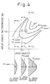
- Fig. 4 is a map for determining the basic diesel fuel supply amount HC base , in which the abscissa represents the space velocity SV, the ordinate the outlet exhaust gas temperature T go and the contour lines the basic diesel fuel supply amount HC base .
- the basic diesel fuel supply amount HC base increases progressively from HC base0 toward HC base3 . Further, Fig. 4 shows cross sections taken in lines X 1 -X 1 , X 2 -X 2 , X 3 -X 3 .
- the basic diesel fuel supply amount HC base assumes an angular shape in the window area with the supply amount which is highest at the center and reduced progressively toward the boundaries. Upon deviation from the window, the supply amount becomes zero. In other words, the height of each cross section represents the basic diesel fuel supply amount HC base .
- the basic diesel fuel supply amount HC base has an angular shape which is progressively higher toward the upper right (in the direction of arrow Y). In this way, the basic diesel fuel supply amount HC base increases.
- Step 408 calculates the temperature difference ⁇ T between the inlet exhaust gas temperature T gi and the outlet exhaust gas temperature T go .
- Step 410 calculates the correcting diesel fuel supply amount ⁇ HC as a function of the temperature difference ⁇ T. ⁇ T ⁇ T gi - T go ⁇ HC ⁇ ⁇ HC ( ⁇ T)
- Fig. 5 is a map for determining the correcting diesel fuel supply amount ⁇ HC, in which the abscissa represents the temperature difference ⁇ T and the ordinate the correcting diesel fuel supply amount ⁇ HC.
- the abscissa is crosses the abscissa at a point "a" representing the state in which the outlet exhaust gas temperature T go is higher than the inlet exhaust gas temperature T gi by the amount of heat generated by the basic diesel fuel supply amount HC base .
- the correcting diesel fuel supply amount ⁇ HC is increased in order to increase the temperature of the lean NO x catalyst.
- diesel fuel supply amount may be corrected after the temperature difference ⁇ T becomes smaller than the temperature which corresponds to 2 ⁇ HC base .
- Fig. 5 shows a linear function.
- Other functions can alternatively be used as far as the relation is held that with the increase in the temperature difference ⁇ T, the correcting diesel fuel supply amount ⁇ HC decreases, while with the decrease in the temperature difference ⁇ T, the correcting diesel fuel supply amount ⁇ HC increases.
- Step 412 calculates the diesel fuel supply amount HC by adding the basic diesel fuel supply amount HC base to the correcting diesel fuel supply amount ⁇ HC.
- Step 414 supplies a pulse train having a duty factor corresponding to the diesel fuel supply amount HC to the solenoid valve 314 through the output interface 334, and thus controls. the amount of the diesel fuel injected from the diesel fuel injection hole 311.
- Fig. 6A and 6B are diagrams for explaining the effects of the present invention, in which the abscissa represents the time, and the ordinate the temperature (upper part) and the diesel fuel supply amount (lower part).
- the solid line represents the inlet exhaust gas temperature T gi and the dashed line the catalyst temperature T c .
- the thick dashed line represents an application of the present invention, and the thin dashed line the case in which the present invention is not applicable.
- the amount of heat received by the lean NO x catalyst increases not only with the temperature increase of the exhaust gas but with the increase in the amount of diesel fuel supplied.
- the catalyst temperature T c gradually increases to such an extent that it deviates from the window at time t 3 .
- the temperature difference ⁇ T between the inlet exhaust gas temperature T gi and the outlet exhaust gas temperature T goes increases.
- the correcting diesel fuel supply amount ⁇ H suppresses the increase in the diesel fuel supply amount.
- the basic diesel fuel supply amount HC base which is determined from the map of the catalyst temperature represented by the outlet exhaust gas temperature T go and the space velocity SV according to the present embodiment, can alternatively be determined from the map of the intake air amount and the rotational speed of the internal combustion engine. In such a case, the speed of the internal combustion engine is detected by the rpm sensor 304.
- this invention can be applied when the vehicle is running under steady state condition and the inlet exhaust gas temperature and the catalyst temperature are within the window.
- diesel fuel is used as a hydrocarbon for reducing NO x in the above-mentioned embodiment
- other hydrocarbon materials such as alcohol can be used with equal effect.
Landscapes
- Engineering & Computer Science (AREA)
- Chemical & Material Sciences (AREA)
- Combustion & Propulsion (AREA)
- Chemical Kinetics & Catalysis (AREA)
- Health & Medical Sciences (AREA)
- Biomedical Technology (AREA)
- General Engineering & Computer Science (AREA)
- Environmental & Geological Engineering (AREA)
- Analytical Chemistry (AREA)
- General Chemical & Material Sciences (AREA)
- Oil, Petroleum & Natural Gas (AREA)
- Mechanical Engineering (AREA)
- Toxicology (AREA)
- Exhaust Gas After Treatment (AREA)
Claims (14)
- Appareil d'épuration des gaz d'émission d'échappement pour un moteur à combustion interne, comprenant :caractérisé parun catalyseur du NOx au rapport air-carburant pauvre (307) disposé dans le tuyau d'échappement (306) d'un moteur à combustion interne (30) ;un moyen d'alimentation en hydrocarbure (311) pour délivrer des hydrocarbures dans les gaz d'échappement pour réduire du NOx en amont dudit catalyseur du NOx ;un moyen de détection de variables d'état (302, 304, 321, 322) pour détecter des variables d'état (Qa, Tgi, Tc) représentant les conditions de fonctionnement dudit catalyseur du NOx au rapport air-carburant pauvre ;un moyen de détermination de quantité d'alimentation en hydrocarbure de base (33) pour déterminer la quantité de base d'hydrocarbure (HCBASE) délivrée depuis lesdits moyens d'alimentation en hydrocarbure (311) en conformité avec les variables d'état détectées par lesdits moyens de détection de variables d'état ; etun moyen de détection de différence de température (321, 322) pour détecter la différence (ΔT) entre la température des gaz d'échappement (Tgi) au niveau de l'entrée dudit catalyseur du NOx au rapport air-carburant pauvre et la température (Tc) du catalyseur du NOx au rapport air-carburant pauvre qui sont inclues dans les variables d'état détectées par ledit moyen de détection de variables d'état,un moyen de correction de quantité d'alimentation en hydrocarbure (33) pour corriger la quantité de base d'hydrocarbure (HCBASE) déterminée par ledit moyen de détermination de quantité d'alimentation en hydrocarbure de base lorsque la différence de température (ΔT) détectée par ledit moyen de détection de différence de température (321, 322) dévie d'une valeur prédéterminée (a ; 2a) correspondant à une quantité de chaleur générée par la quantité de base d'hydrocarbure (HCBASE) délivrée depuis ledit moyen d'alimentation en hydrocarbure (311) de façon à empêcher que la température (Tc) dudit catalyseur du NOx au rapport air-carburant pauvre puisse dévier à l'extérieur d'une fenêtre de température établie pour obtenir un taux d'épuration correct.
- Appareil d'épuration des gaz d'émission d'échappement pour des moteurs à combustion interne selon la revendication 1, dans lequel ladite valeur prédéterminée (a ; 2a) est plus grande lorsque la température des gaz d'échappement (Tgi) au niveau de l'entrée dudit catalyseur du NOx au rapport air-carburant pauvre chute.
- Appareil d'épuration des gaz d'émission d'échappement pour des moteurs à combustion interne selon la revendication 1 ou 2, dans lequel ledit moyen de correction de quantité d'alimentation en hydrocarbure (33) utilise une fonction linéaire pour corriger la quantité de base d'hydrocarbure (HCbase) en conformité avec la différence de température ΔT.
- Appareil d'épuration des gaz d'émission d'échappement pour des moteurs à combustion interne selon la revendication 1, dans lequel ledit moyen de détection de variables d'état inclut un moyen de détection de quantité d'air d'admission (302) pour détecter la quantité d'air d'admission (Qa) du moteur à combustion interne, et un moyen de détection de température du catalyseur au rapport air-carburant pauvre (322) pour détecter la température (Tc) dudit catalyseur du NOx au rapport air-carburant pauvre.
- Appareil d'épuration des gaz d'émission d'échappement pour des moteurs à combustion interne selon la revendication 4, dans lequel ledit moyen de détection de température du catalyseur au rapport air-carburant pauvre (322) détecte la température des gaz d'échappement (Tgo) au niveau de la sortie dudit catalyseur du NOx au rapport air-carburant pauvre.
- Appareil d'épuration des gaz d'émission d'échappement pour des moteurs à combustion interne selon la revendication 1, dans lequel ledit moyen de détection de variables d'état inclut un moyen de détection de quantité d'air d'admission (302) pour détecter la quantité d'air d'admission (Qa) du moteur à combustion interne, et un moyen de détection de vitesse du moteur (304) pour détecter la vitesse de rotation du moteur à combustion interne.
- Appareil d'épuration des gaz d'émission d'échappement pour des moteurs à combustion interne selon la revendication 1, dans lequel ledit moyen de détection de différence de température (321, 322) détecte la différence (ΔT) de la température des gaz d'échappement entre l'entrée et la sortie dudit catalyseur du NOx au rapport air-carburant pauvre.
- Procédé d'épuration des gaz d'émission d'échappement pour des moteurs à combustion interne, comprenant les étapes consistant à :caractérisé pardélivrer des hydrocarbures dans les gaz d'échappement pour réduire le NOx en amont d'un catalyseur du NOx au rapport air-carburant pauvre (307) disposé dans le tuyau d'échappement (306) d'un moteur à combustion interne (30) ;détecter des variables d'état (Qa, Tgi, Tc) représentant les conditions de fonctionnement dudit catalyseur du NOx au rapport air-carburant pauvre ; etdéterminer la quantité de base d'hydrocarbure (HCbase) délivré dans ladite étape d'alimentation en hydrocarbure en conformité avec les variables d'état détectées dans ladite étape de détection des variables d'état ; etdétecter la différence (ΔT) entre la température des gaz d'échappement (Tgi) au niveau de l'entrée dudit catalyseur du NOx au rapport air-carburant pauvre et la température (Tc) dudit catalyseur du NOx au rapport air-carburant pauvre qui sont inclues dans les variables d'état détectées dans ladite étape de détection des variables d'état,corriger la quantité de base d'hydrocarbure (HCbase) déterminé dans ladite étape de détermination de quantité d'alimentation en hydrocarbure de base lorsque la différence de température (ΔT) détectée dans ladite étape de détection de différence de température dévie d'une valeur prédéterminée (a ; 2a) correspondant à une quantité de chaleur générée par la quantité de base d'hydrocarbure (HCbase) délivrée dans ladite étape d'alimentation en hydrocarbure de façon à empêcher que la température (Tc) dudit catalyseur du NOx au rapport air-carburant pauvre puisse dévier à l'extérieur d'une fenêtre de température établie pour obtenir un taux d'épuration correct.
- Procédé d'épuration des gaz d'émission d'échappement pour des moteurs à combustion interne selon la revendication 8, dans lequel ladite valeur prédéterminée (a ; 2a) est plus grande lorsque la température des gaz d'échappement (Tgi) au niveau de l'entrée dudit catalyseur du NOx au rapport air-carburant pauvre chute.
- Procédé d'épuration des gaz d'émission d'échappement pour des moteurs à combustion interne selon la revendication 8 ou 9, dans lequel ladite étape de correction de quantité d'alimentation en hydrocarbure utilise une fonction linéaire pour corriger la quantité de base d'hydrocarbure (HCbase) en conformité avec la différence de température (ΔT).
- Procédé d'épuration des gaz d'émission d'échappement pour des moteurs à combustion interne selon la revendication 8, dans lequel ladite étape de détection des variables d'état inclut les étapes consistant à détecter la quantité d'air d'admission (Qa) du moteur à combustion interne, et à détecter la température (Tc) dudit catalyseur du NOx au rapport air-carburant pauvre.
- Procédé d'épuration des gaz d'émission d'échappement pour des moteurs à combustion interne selon la revendication 11, dans lequel dans ladite étape de détection de température du catalyseur au rapport air-carburant pauvre, la température des gaz d'échappement (Tgo) est détectée au niveau de la sortie du catalyseur du NOx au rapport air-carburant pauvre.
- Procédé d'épuration des gaz d'émission d'échappement pour des moteurs à combustion interne selon la revendication 8, dans lequel ladite étape de détection des variables d'état inclut les étapes consistant à détecter la quantité d'air d'admission (Qa) du moteur à combustion interne, et à détecter la vitesse de rotation du moteur à combustion interne.
- Procédé d'épuration des gaz d'émission d'échappement pour des moteurs à combustion interne selon la revendication 8, dans lequel dans ladite étape de détection de différence de température, la différence (ΔT) dans la température des gaz d'échappement est détectée entre l'entrée et la sortie dudit catalyseur du NOx au rapport air-carburant pauvre.
Applications Claiming Priority (3)
| Application Number | Priority Date | Filing Date | Title |
|---|---|---|---|
| JP8204954A JPH1047048A (ja) | 1996-08-02 | 1996-08-02 | 内燃機関の排気浄化装置 |
| JP20495496 | 1996-08-02 | ||
| JP204954/96 | 1996-08-02 |
Publications (2)
| Publication Number | Publication Date |
|---|---|
| EP0822323A1 EP0822323A1 (fr) | 1998-02-04 |
| EP0822323B1 true EP0822323B1 (fr) | 2003-04-16 |
Family
ID=16499071
Family Applications (1)
| Application Number | Title | Priority Date | Filing Date |
|---|---|---|---|
| EP97113359A Expired - Lifetime EP0822323B1 (fr) | 1996-08-02 | 1997-08-01 | Dispositif et méthode pour l'épuration des gaz d'échappement d'un moteur à combustion interne |
Country Status (4)
| Country | Link |
|---|---|
| US (1) | US5842341A (fr) |
| EP (1) | EP0822323B1 (fr) |
| JP (1) | JPH1047048A (fr) |
| DE (1) | DE69720883T2 (fr) |
Families Citing this family (64)
| Publication number | Priority date | Publication date | Assignee | Title |
|---|---|---|---|---|
| JP3157061B2 (ja) * | 1993-04-26 | 2001-04-16 | 株式会社日立製作所 | 触媒劣化診断システム |
| DE19704558A1 (de) * | 1997-02-06 | 1998-08-13 | Siemens Ag | Verfahren und Einrichtung zur katalytischen Abgasreinigung sowie Verbrennungsanlage |
| DE19736384A1 (de) * | 1997-08-21 | 1999-02-25 | Man Nutzfahrzeuge Ag | Verfahren zur Dosierung eines Reduktionsmittels in stickoxidhaltiges Abgas einer Brennkraftmaschine |
| DE19749400C2 (de) * | 1997-11-07 | 2001-11-29 | Siemens Ag | Verfahren zur Verringerung des NOX-Gehaltes im Abgas einer Dieselbrennkraftmaschine |
| DE19818448A1 (de) * | 1998-04-24 | 1999-10-28 | Siemens Ag | Verfahren und Vorrichtung zur katalytischen Reduzierung von Stickoxiden im Abgas einer Verbrennungsanlage |
| DE19843136A1 (de) * | 1998-09-21 | 2000-03-30 | Siemens Ag | Abgasreinigungsanlage und Verfahren zur katalytischen Verringerung des Schadstoffgehalts im Abgas einer Verbrennungsanlage |
| DE19843423A1 (de) * | 1998-09-22 | 2000-03-30 | Siemens Ag | Verfahren und Vorrichtung zur katalytischen Beseitigung eines Schadstoffes aus dem Abgas einer Verbrennungsanlage |
| US6357226B2 (en) * | 1998-10-22 | 2002-03-19 | Chrysler Corporation | Control system for lean air-fuel ratio NOx catalyst system |
| DE59913222D1 (de) * | 1998-12-11 | 2006-05-11 | Argillon Gmbh | Steuersystem für eine Abgasnachbehandlungseinrichtung einer Brennkraftmaschine |
| WO2000043469A2 (fr) * | 1999-01-21 | 2000-07-27 | Litex, Inc. | Systemes catalyseurs combines a reacteur a plasma destines a la reduction efficace des emissions dans de multiples conditions de fonctionnement |
| DE19903439A1 (de) * | 1999-01-29 | 2000-08-03 | Bosch Gmbh Robert | Verfahren und Vorrichtung zur Steuerung eines Abgasnachbehandlungssystem |
| US6295809B1 (en) * | 1999-07-12 | 2001-10-02 | Ford Global Technologies, Inc. | Emission control system with a catalyst |
| DE19932715A1 (de) * | 1999-07-16 | 2001-01-18 | Volkswagen Ag | Verfahren zur Zustandserfassung eines Katalysatorsystems |
| DE19959605A1 (de) * | 1999-12-10 | 2001-06-13 | Volkswagen Ag | Vorrichtung und Verfahren zur NOx- und/oder SOx-Regeneration eines NOx-Speicherkatalysators |
| US6311484B1 (en) * | 2000-02-22 | 2001-11-06 | Engelhard Corporation | System for reducing NOx transient emission |
| US6363713B1 (en) * | 2000-07-20 | 2002-04-02 | Ford Global Technologies, Inc. | On-board diagnostics for detecting the operation of diesel emissions control system |
| US6408616B1 (en) * | 2000-07-20 | 2002-06-25 | Ford Global Technologies, Inc. | Diesel OBD-II system for detection of degradation of catalyst activity |
| US6415602B1 (en) | 2000-10-16 | 2002-07-09 | Engelhard Corporation | Control system for mobile NOx SCR applications |
| JP3719127B2 (ja) * | 2000-10-25 | 2005-11-24 | トヨタ自動車株式会社 | NOx排出抑止型ハイブリッド車 |
| JP3982178B2 (ja) | 2000-10-27 | 2007-09-26 | トヨタ自動車株式会社 | 有害ガス成分排出抑制型車輌 |
| DE10056016A1 (de) * | 2000-11-11 | 2002-05-16 | Bosch Gmbh Robert | Verfahren und Vorrichtung zur Steuerung eines Abgasnachbehandlungssystems |
| DE10113010A1 (de) * | 2001-03-17 | 2002-09-19 | Bosch Gmbh Robert | Verfahren und Vorrichtung zur Überwachung eines Abgasnachbehandlungssystems |
| US6449945B1 (en) * | 2001-04-18 | 2002-09-17 | Ford Global Technologies, Inc. | Emission control system |
| JP4122849B2 (ja) * | 2001-06-22 | 2008-07-23 | 株式会社デンソー | 触媒劣化検出装置 |
| US6698191B2 (en) * | 2001-08-09 | 2004-03-02 | Ford Global Technologies, Llc | High efficiency conversion of nitrogen oxides in an exhaust aftertreatment device at low temperature |
| US6546720B2 (en) | 2001-09-04 | 2003-04-15 | Ford Global Technologies, Inc. | Method and apparatus for controlling the amount of reactant to be added to a substance using a sensor which is responsive to both the reactant and the substance |
| US7121085B2 (en) * | 2001-09-04 | 2006-10-17 | Ford Global Technologies, Llc | Method and apparatus for controlling hydrocarbon injection into engine exhaust to reduce NOx |
| US6487852B1 (en) | 2001-09-04 | 2002-12-03 | Ford Global Technologies, Inc. | Method and apparatus for controlling reactant injection into an active lean NOx catalyst |
| JP4720054B2 (ja) * | 2001-09-11 | 2011-07-13 | トヨタ自動車株式会社 | 内燃機関の排気浄化装置 |
| US6948310B2 (en) * | 2002-10-01 | 2005-09-27 | Southwest Res Inst | Use of a variable valve actuation system to control the exhaust gas temperature and space velocity of aftertreatment system feedgas |
| US20040083722A1 (en) * | 2002-11-06 | 2004-05-06 | Ford Global Technologies, Inc. | Diesel aftertreatment systems |
| US6895747B2 (en) | 2002-11-21 | 2005-05-24 | Ford Global Technologies, Llc | Diesel aftertreatment systems |
| US6862879B2 (en) | 2002-11-21 | 2005-03-08 | Ford Global Technologies, Llc | Diesel aftertreatment system |
| US6834498B2 (en) * | 2002-11-21 | 2004-12-28 | Ford Global Technologies, Llc | Diesel aftertreatment systems |
| DE10301602A1 (de) * | 2003-01-17 | 2004-07-29 | Robert Bosch Gmbh | Verfahren und Vorrichtung zum Betreiben einer Dosiereinheit eines Katalysators |
| EP1477655A1 (fr) * | 2003-05-13 | 2004-11-17 | Haldor Topsoe A/S | Procédé d'injection contrôlée d'un agent réducteur dans des gaz d'échappement contenant des oxydes d'azote |
| US7861516B2 (en) * | 2003-06-18 | 2011-01-04 | Johnson Matthey Public Limited Company | Methods of controlling reductant addition |
| GB0428289D0 (en) * | 2004-12-24 | 2005-01-26 | Johnson Matthey Plc | Reductant addition in exhaust system comprising NOx-absorbent |
| GB0428291D0 (en) * | 2004-12-24 | 2005-01-26 | Johnson Matthey Plc | Methods of regenerating NOx-Absorbent |
| FR2873163B1 (fr) * | 2004-07-15 | 2008-06-27 | Peugeot Citroen Automobiles Sa | Systeme de controle du fonctionnement d'un moteur diesel de vehicule automobile associe a un catalyseur d'oxydation |
| US7178328B2 (en) * | 2004-12-20 | 2007-02-20 | General Motors Corporation | System for controlling the urea supply to SCR catalysts |
| JP2006233936A (ja) * | 2005-02-28 | 2006-09-07 | Mitsubishi Fuso Truck & Bus Corp | 内燃機関の排気浄化装置 |
| JP2006274911A (ja) * | 2005-03-29 | 2006-10-12 | Mitsubishi Fuso Truck & Bus Corp | 後処理装置の昇温制御装置 |
| US7216478B2 (en) * | 2005-06-03 | 2007-05-15 | Gm Global Technology Operations, Inc. | Exhaust treatment diagnostic using a temperature sensor |
| JP2007064167A (ja) * | 2005-09-02 | 2007-03-15 | Toyota Motor Corp | 内燃機関の排気浄化装置および排気浄化方法 |
| JP4240025B2 (ja) * | 2005-09-02 | 2009-03-18 | トヨタ自動車株式会社 | 排気浄化装置 |
| US8544258B2 (en) * | 2005-09-23 | 2013-10-01 | GM Global Technology Operations LLC | Exhaust treatment system diagnostic via ammonium nitrite decomposition |
| JP4395120B2 (ja) * | 2005-10-19 | 2010-01-06 | トヨタ自動車株式会社 | 内燃機関の排気ガス浄化装置 |
| JP4710564B2 (ja) * | 2005-11-22 | 2011-06-29 | いすゞ自動車株式会社 | 排気ガス浄化システムの制御方法及び排気ガス浄化システム |
| US7861518B2 (en) * | 2006-01-19 | 2011-01-04 | Cummins Inc. | System and method for NOx reduction optimization |
| US9103248B2 (en) | 2006-01-19 | 2015-08-11 | Cummins Inc. | Method and system for optimizing fuel and reductant consumption |
| JP2007255310A (ja) * | 2006-03-23 | 2007-10-04 | Mitsubishi Fuso Truck & Bus Corp | 排気浄化装置 |
| US8713917B2 (en) * | 2007-08-30 | 2014-05-06 | GM Global Technology Operations LLC | Method for reducing NH3 release from SCR catalysts during thermal transients |
| DE102007044607B4 (de) * | 2007-09-19 | 2014-03-27 | Continental Automotive Gmbh | Verfahren zum Anpassen einer Eindüsung eines Reduktionsmittels stromaufwärts eines SCR-Katalysators und zum Betrieb eines SCR- Katalysators |
| DE102008044222B4 (de) * | 2008-12-01 | 2019-04-18 | Ford Global Technologies, Llc | Verfahren und Vorrichtung zur Abschätzung der Reduktionsmittelkonzentration in Abgasen |
| US7845336B2 (en) * | 2008-12-18 | 2010-12-07 | Caterpillar Inc | Fuel delivery system having electric pump |
| US8166749B2 (en) * | 2009-02-12 | 2012-05-01 | GM Global Technology Operations LLC | Exhaust treatment diagnostic system and method |
| US8281571B2 (en) * | 2009-03-06 | 2012-10-09 | Detroit Diesel Corporation | Method for three zone diesel oxidation catalyst light off control system |
| US8245502B2 (en) * | 2009-06-16 | 2012-08-21 | Ford Global Technologies, Llc | Emission control system with an optimized reductant injection model |
| US20110232270A1 (en) * | 2010-03-23 | 2011-09-29 | Burkitt Joseph S | Fuel system having multi-functional electric pump |
| US8973563B2 (en) * | 2010-04-20 | 2015-03-10 | Toyota Jidosha Kabushiki Kaisha | Internal combustion engine control apparatus |
| US8504280B2 (en) | 2010-09-21 | 2013-08-06 | GM Global Technology Operations LLC | Fuel control diagnostic system and method |
| US20120222399A1 (en) * | 2011-03-03 | 2012-09-06 | GM Global Technology Operations LLC | Oxidation catalyst burn threshold adjustment to avoid quenching |
| US10450934B2 (en) | 2016-08-04 | 2019-10-22 | Mitsui Mining & Smelting Co., Ltd. | Catalyst deterioration detecting system and catalyst deterioration detecting method |
Family Cites Families (6)
| Publication number | Priority date | Publication date | Assignee | Title |
|---|---|---|---|---|
| JP2825137B2 (ja) * | 1990-06-25 | 1998-11-18 | トヨタ自動車株式会社 | 内燃機関の排気浄化装置 |
| US5201802A (en) * | 1991-02-04 | 1993-04-13 | Toyota Jidosha Kabushiki Kaisha | Exhaust gas purification system for an internal combustion engine |
| NL9200338A (nl) * | 1992-02-25 | 1993-05-03 | Deltec Fuel Systems Bv | Regelstelsel voor het toevoeren van een brandstof-luchtmengsel aan een motor alsmede werkwijze voor het regelen van de samenstelling van de uitlaatgasstroom van een verbrandingsmotor. |
| JPH0849526A (ja) * | 1994-08-09 | 1996-02-20 | Nissan Diesel Motor Co Ltd | エンジンの排気浄化装置 |
| DE4436415A1 (de) * | 1994-10-12 | 1996-04-18 | Bosch Gmbh Robert | Einrichtung zum Nachbehandeln von Abgasen einer selbstzündenden Brennkraftmaschine |
| JPH08158859A (ja) * | 1994-12-06 | 1996-06-18 | Nippon Soken Inc | 内燃機関の排気浄化装置 |
-
1996
- 1996-08-02 JP JP8204954A patent/JPH1047048A/ja active Pending
-
1997
- 1997-07-31 US US08/903,706 patent/US5842341A/en not_active Expired - Fee Related
- 1997-08-01 EP EP97113359A patent/EP0822323B1/fr not_active Expired - Lifetime
- 1997-08-01 DE DE69720883T patent/DE69720883T2/de not_active Expired - Fee Related
Also Published As
| Publication number | Publication date |
|---|---|
| US5842341A (en) | 1998-12-01 |
| DE69720883T2 (de) | 2003-12-11 |
| EP0822323A1 (fr) | 1998-02-04 |
| JPH1047048A (ja) | 1998-02-17 |
| DE69720883D1 (de) | 2003-05-22 |
Similar Documents
| Publication | Publication Date | Title |
|---|---|---|
| EP0822323B1 (fr) | Dispositif et méthode pour l'épuration des gaz d'échappement d'un moteur à combustion interne | |
| US7159391B2 (en) | Method for restricting excessive temperature rise of filter in internal combustion engine | |
| EP0933521B1 (fr) | Appareil et méthode de commande de rapport air-carburant pour moteur | |
| US6892527B2 (en) | Catalyst deterioration suppressing apparatus and method | |
| US6282889B1 (en) | Air/fuel ration control system of internal combustion engine | |
| EP1882088B1 (fr) | Systeme de purification des gaz d'echappement destine a un moteur a combustion interne | |
| JPH04209957A (ja) | 内燃機関の制御装置 | |
| EP0770767B1 (fr) | Dispositif pour la détection de la détérioration d'un catalyseur pour un moteur à combustion interne | |
| US6253546B1 (en) | Torque control scheme for low emission lean burn vehicle | |
| US8033097B2 (en) | Exhaust control device for an internal combustion engine | |
| US20030079716A1 (en) | Apparatus and a method for controlling an internal combustion engine | |
| US7051516B2 (en) | Method for controlling a working mode of an internal combustion engine | |
| JP3988518B2 (ja) | 内燃機関の排ガス浄化装置 | |
| US4823270A (en) | Method and apparatus for controlling air-fuel ratio in internal combustion engine | |
| JPH0551773B2 (fr) | ||
| JP4888368B2 (ja) | 内燃機関の制御装置 | |
| JPH0689686B2 (ja) | エンジンの空燃比制御装置 | |
| JP4247616B2 (ja) | ディーゼルエンジンの燃料噴射制御装置 | |
| JP4687484B2 (ja) | 内燃機関の排気浄化システム | |
| JP2639157B2 (ja) | 内燃機関の排気浄化装置 | |
| JPH0559935A (ja) | 内燃エンジンの触媒劣化防止装置 | |
| JP2809236B2 (ja) | 内燃機関の排気浄化装置 | |
| JP2784014B2 (ja) | エンジンの空燃比制御装置 | |
| JPH05106482A (ja) | エンジンの回転数制御装置 | |
| JPH04209956A (ja) | 内燃機関の制御装置 |
Legal Events
| Date | Code | Title | Description |
|---|---|---|---|
| PUAI | Public reference made under article 153(3) epc to a published international application that has entered the european phase |
Free format text: ORIGINAL CODE: 0009012 |
|
| 17P | Request for examination filed |
Effective date: 19970801 |
|
| AK | Designated contracting states |
Kind code of ref document: A1 Designated state(s): DE FR GB |
|
| AKX | Designation fees paid |
Free format text: DE FR GB |
|
| RBV | Designated contracting states (corrected) |
Designated state(s): DE FR GB |
|
| 17Q | First examination report despatched |
Effective date: 20001228 |
|
| GRAH | Despatch of communication of intention to grant a patent |
Free format text: ORIGINAL CODE: EPIDOS IGRA |
|
| RTI1 | Title (correction) |
Free format text: AN EXHAUST EMISSION PURIFICATION APPARATUS AND METHOD FOR AN INTERNAL COMBUSTION ENGINE |
|
| GRAH | Despatch of communication of intention to grant a patent |
Free format text: ORIGINAL CODE: EPIDOS IGRA |
|
| GRAA | (expected) grant |
Free format text: ORIGINAL CODE: 0009210 |
|
| AK | Designated contracting states |
Designated state(s): DE FR GB |
|
| REG | Reference to a national code |
Ref country code: GB Ref legal event code: FG4D |
|
| REF | Corresponds to: |
Ref document number: 69720883 Country of ref document: DE Date of ref document: 20030522 Kind code of ref document: P |
|
| ET | Fr: translation filed | ||
| PLBE | No opposition filed within time limit |
Free format text: ORIGINAL CODE: 0009261 |
|
| STAA | Information on the status of an ep patent application or granted ep patent |
Free format text: STATUS: NO OPPOSITION FILED WITHIN TIME LIMIT |
|
| 26N | No opposition filed |
Effective date: 20040119 |
|
| PGFP | Annual fee paid to national office [announced via postgrant information from national office to epo] |
Ref country code: GB Payment date: 20040728 Year of fee payment: 8 |
|
| PGFP | Annual fee paid to national office [announced via postgrant information from national office to epo] |
Ref country code: FR Payment date: 20040810 Year of fee payment: 8 |
|
| PGFP | Annual fee paid to national office [announced via postgrant information from national office to epo] |
Ref country code: DE Payment date: 20040812 Year of fee payment: 8 |
|
| PG25 | Lapsed in a contracting state [announced via postgrant information from national office to epo] |
Ref country code: GB Free format text: LAPSE BECAUSE OF NON-PAYMENT OF DUE FEES Effective date: 20050801 |
|
| PG25 | Lapsed in a contracting state [announced via postgrant information from national office to epo] |
Ref country code: DE Free format text: LAPSE BECAUSE OF NON-PAYMENT OF DUE FEES Effective date: 20060301 |
|
| GBPC | Gb: european patent ceased through non-payment of renewal fee |
Effective date: 20050801 |
|
| PG25 | Lapsed in a contracting state [announced via postgrant information from national office to epo] |
Ref country code: FR Free format text: LAPSE BECAUSE OF NON-PAYMENT OF DUE FEES Effective date: 20060428 |
|
| REG | Reference to a national code |
Ref country code: FR Ref legal event code: ST Effective date: 20060428 |