CN1280103C - Cartriage and connecting assembly for ink-jet printer and ink-jet printer - Google Patents
Cartriage and connecting assembly for ink-jet printer and ink-jet printer Download PDFInfo
- Publication number
- CN1280103C CN1280103C CNB2003101023498A CN200310102349A CN1280103C CN 1280103 C CN1280103 C CN 1280103C CN B2003101023498 A CNB2003101023498 A CN B2003101023498A CN 200310102349 A CN200310102349 A CN 200310102349A CN 1280103 C CN1280103 C CN 1280103C
- Authority
- CN
- China
- Prior art keywords
- ink
- storage chamber
- port
- connection
- connection port
- Prior art date
- Legal status (The legal status is an assumption and is not a legal conclusion. Google has not performed a legal analysis and makes no representation as to the accuracy of the status listed.)
- Expired - Fee Related
Links
Images


Classifications
-
- B—PERFORMING OPERATIONS; TRANSPORTING
- B41—PRINTING; LINING MACHINES; TYPEWRITERS; STAMPS
- B41J—TYPEWRITERS; SELECTIVE PRINTING MECHANISMS, i.e. MECHANISMS PRINTING OTHERWISE THAN FROM A FORME; CORRECTION OF TYPOGRAPHICAL ERRORS
- B41J2/00—Typewriters or selective printing mechanisms characterised by the printing or marking process for which they are designed
- B41J2/005—Typewriters or selective printing mechanisms characterised by the printing or marking process for which they are designed characterised by bringing liquid or particles selectively into contact with a printing material
- B41J2/01—Ink jet
- B41J2/17—Ink jet characterised by ink handling
- B41J2/175—Ink supply systems ; Circuit parts therefor
- B41J2/17503—Ink cartridges
- B41J2/1752—Mounting within the printer
- B41J2/17523—Ink connection
-
- B—PERFORMING OPERATIONS; TRANSPORTING
- B41—PRINTING; LINING MACHINES; TYPEWRITERS; STAMPS
- B41J—TYPEWRITERS; SELECTIVE PRINTING MECHANISMS, i.e. MECHANISMS PRINTING OTHERWISE THAN FROM A FORME; CORRECTION OF TYPOGRAPHICAL ERRORS
- B41J2/00—Typewriters or selective printing mechanisms characterised by the printing or marking process for which they are designed
- B41J2/005—Typewriters or selective printing mechanisms characterised by the printing or marking process for which they are designed characterised by bringing liquid or particles selectively into contact with a printing material
- B41J2/01—Ink jet
- B41J2/17—Ink jet characterised by ink handling
- B41J2/175—Ink supply systems ; Circuit parts therefor
- B41J2/17503—Ink cartridges
- B41J2/17513—Inner structure
-
- B—PERFORMING OPERATIONS; TRANSPORTING
- B41—PRINTING; LINING MACHINES; TYPEWRITERS; STAMPS
- B41J—TYPEWRITERS; SELECTIVE PRINTING MECHANISMS, i.e. MECHANISMS PRINTING OTHERWISE THAN FROM A FORME; CORRECTION OF TYPOGRAPHICAL ERRORS
- B41J2/00—Typewriters or selective printing mechanisms characterised by the printing or marking process for which they are designed
- B41J2/005—Typewriters or selective printing mechanisms characterised by the printing or marking process for which they are designed characterised by bringing liquid or particles selectively into contact with a printing material
- B41J2/01—Ink jet
- B41J2/17—Ink jet characterised by ink handling
- B41J2/175—Ink supply systems ; Circuit parts therefor
- B41J2/17503—Ink cartridges
- B41J2/1752—Mounting within the printer
-
- B—PERFORMING OPERATIONS; TRANSPORTING
- B41—PRINTING; LINING MACHINES; TYPEWRITERS; STAMPS
- B41J—TYPEWRITERS; SELECTIVE PRINTING MECHANISMS, i.e. MECHANISMS PRINTING OTHERWISE THAN FROM A FORME; CORRECTION OF TYPOGRAPHICAL ERRORS
- B41J2/00—Typewriters or selective printing mechanisms characterised by the printing or marking process for which they are designed
- B41J2/005—Typewriters or selective printing mechanisms characterised by the printing or marking process for which they are designed characterised by bringing liquid or particles selectively into contact with a printing material
- B41J2/01—Ink jet
- B41J2/17—Ink jet characterised by ink handling
- B41J2/175—Ink supply systems ; Circuit parts therefor
- B41J2/17503—Ink cartridges
- B41J2/17553—Outer structure
-
- B—PERFORMING OPERATIONS; TRANSPORTING
- B41—PRINTING; LINING MACHINES; TYPEWRITERS; STAMPS
- B41J—TYPEWRITERS; SELECTIVE PRINTING MECHANISMS, i.e. MECHANISMS PRINTING OTHERWISE THAN FROM A FORME; CORRECTION OF TYPOGRAPHICAL ERRORS
- B41J2/00—Typewriters or selective printing mechanisms characterised by the printing or marking process for which they are designed
- B41J2/005—Typewriters or selective printing mechanisms characterised by the printing or marking process for which they are designed characterised by bringing liquid or particles selectively into contact with a printing material
- B41J2/01—Ink jet
- B41J2/17—Ink jet characterised by ink handling
- B41J2/175—Ink supply systems ; Circuit parts therefor
- B41J2/17503—Ink cartridges
- B41J2/17556—Means for regulating the pressure in the cartridge
-
- B—PERFORMING OPERATIONS; TRANSPORTING
- B41—PRINTING; LINING MACHINES; TYPEWRITERS; STAMPS
- B41J—TYPEWRITERS; SELECTIVE PRINTING MECHANISMS, i.e. MECHANISMS PRINTING OTHERWISE THAN FROM A FORME; CORRECTION OF TYPOGRAPHICAL ERRORS
- B41J2/00—Typewriters or selective printing mechanisms characterised by the printing or marking process for which they are designed
- B41J2/005—Typewriters or selective printing mechanisms characterised by the printing or marking process for which they are designed characterised by bringing liquid or particles selectively into contact with a printing material
- B41J2/01—Ink jet
- B41J2/17—Ink jet characterised by ink handling
- B41J2/175—Ink supply systems ; Circuit parts therefor
- B41J2/17596—Ink pumps, ink valves
Landscapes
- Ink Jet (AREA)
Abstract
本发明涉及一种连接组件、喷墨打印机、墨水袋和墨水供给系统。该连接组件连接墨盒和打印头;墨盒包括墨水贮存室,与上述墨水贮存室连通的、在墨盒未附着在连接组件的第一状态维持闭合状态的大气连通用连接口,与上述墨水贮存室连通的、在第一状态维持闭合状态的墨水供给用连接口;连接组件包括:一沿垂直方向延伸的贮墨室;一负压发生系统;一设置在贮墨室上部的、与墨盒的大气连通用连接口相连的大气连通用连接口;一设置在贮墨室下部的与墨盒的墨水供给连接口相连的墨水流入用连接口;和一将贮墨室内的墨水供给打印头的墨口;其中,连接口分别设置有阀体,当墨盒附着在连接组件上时,所述阀体呈开放状态,其它时间,所述阀体维持闭合状态。
The invention relates to a connection assembly, an inkjet printer, an ink bag and an ink supply system. The connection assembly connects the ink cartridge and the print head; the ink cartridge includes an ink storage chamber, and the air communication common connection port that communicates with the ink storage chamber and maintains a closed state in the first state that the ink cartridge is not attached to the connection assembly communicates with the ink storage chamber The connection port for ink supply that maintains a closed state in the first state; the connection assembly includes: an ink storage chamber extending in the vertical direction; a negative pressure generating system; The general connecting port is connected to the atmospheric connection port; one is arranged on the lower part of the ink storage chamber and the ink supply connection port of the ink cartridge is connected to the ink inflow connection port; and the ink in the ink storage chamber is supplied to the ink port of the print head; wherein The connection ports are respectively provided with valve bodies, and when the ink cartridge is attached to the connection assembly, the valve bodies are in an open state, and at other times, the valve bodies are maintained in a closed state.
Description
本发明是2001年02月15日申请的发明名称为“喷墨打印机用墨盒和连接组件以及喷墨打印机”的第01103930.2号发明专利申请的分案申请。The present invention is a divisional application of the No. 01103930.2 invention patent application filed on February 15, 2001 with the title of "ink cartridge and connection assembly for inkjet printer and inkjet printer".
技术领域technical field
本发明涉及根据印刷信号将墨水滴排出提供给喷墨打印头的墨盒和连接组件等的墨水供给机构及利用它们的打印机。The present invention relates to an ink supply mechanism that discharges ink droplets to an inkjet print head, an ink cartridge, a connection unit, etc. according to a printing signal, and a printer using the same.
背景技术Background technique
将墨盒可装拆地装载在有喷墨打印头的托架上,从墨盒向打印头提供墨水的打印机,例如,欧洲专利公开第562717号公报所示,使用一种把墨水装在挠性墨水袋内,再把该墨水袋容纳在硬壳内的墨盒。An ink cartridge is detachably loaded on a carriage with an inkjet print head, and a printer that supplies ink from the ink cartridge to the print head, for example, as shown in European Patent Publication No. 562717, uses a flexible ink that contains ink In the bag, the ink bag is contained in the ink cartridge in the hard case.
根据这种构成的墨盒,与将墨水含浸在多孔质体内而构成的墨盒相比较,因为不存在多孔质体,所以能够有效地利用容器的容积容纳更多的墨水,可提高墨水的相对容积比。According to the ink cartridge of this structure, compared with the ink cartridge formed by impregnating ink in the porous body, because there is no porous body, it can effectively use the volume of the container to accommodate more ink, and the relative volume ratio of the ink can be increased. .
然而,因为墨水由多孔质体的毛细管张力保持着,所容纳的墨水的液柱直接作用于打印头上,因墨水量的变化,作用于打印头上的墨水压力也发生变化,此外,托架的往返运动造成墨水摇动引起的压力变化也作用于打印头上,导致印刷质量的下降。However, because the ink is held by the capillary tension of the porous body, the liquid column of the contained ink directly acts on the print head, and the ink pressure acting on the print head changes due to the change in the amount of ink. In addition, the carriage The pressure change caused by ink shaking caused by the reciprocating movement of the ink also acts on the print head, resulting in a decline in printing quality.
发明内容Contents of the invention
本发明的墨盒是一种经墨水供给口向打印头供给墨水贮存室内的墨水的墨盒,在上述墨水贮存室和上述墨水供给口之间配置一负压发生系统,该负压发生系统将上述墨水供给口的压力维持在比上述墨水贮存室的压力低一定值的状态。The ink cartridge of the present invention is an ink cartridge that supplies the ink in the ink storage chamber to the print head through the ink supply port, and a negative pressure generating system is arranged between the above-mentioned ink storage chamber and the above-mentioned ink supply port. The pressure of the supply port is maintained at a constant value lower than the pressure of the ink storage chamber.
本发明另外的墨盒具备墨水贮存室,与上述墨水贮存室的上部连通的、在未装在打印机上的状态下将阀维持在闭合状态的筒状大气连通用连接口,与上述墨水贮存室下部连通的、在未装在打印机上的状态下将阀维持在闭合状态的筒状墨水供给用连接口,经过设置在打印机上的具备负压发生系统的连接组件向打印头供给墨水。Another ink cartridge of the present invention is provided with an ink storage chamber, and a cylindrical atmospheric communication connection port that communicates with the upper part of the ink storage chamber and maintains the valve in a closed state when it is not mounted on the printer is connected with the lower part of the ink storage chamber. The connected cylindrical ink supply connection port, which maintains the valve in the closed state when it is not installed in the printer, supplies ink to the print head through the connection unit equipped with the negative pressure generating system provided on the printer.
因而,本发明的第1目的是提供一种与墨水量的变化和托架的移动无关地可向打印头供给一定压力的墨水的墨盒。Therefore, a first object of the present invention is to provide an ink cartridge capable of supplying ink at a constant pressure to the print head regardless of changes in the amount of ink or movement of the carriage.
本发明的第2目的是提供一种与墨水量的变化和托架的移动无关地可向打印头供给一定压力的墨水、连接墨盒和打印头的连接组件。A second object of the present invention is to provide a connection unit that can supply ink at a constant pressure to the print head regardless of changes in the amount of ink or movement of the carriage, and connect the ink cartridge and the print head.
本发明的第3目的是提供一种使用这些墨盒、连接组件的打印机。A third object of the present invention is to provide a printer using these ink cartridges and connection units.
根据上述目的,本发明提供一种喷墨打印机用连接组件,该连接组件连接墨盒和打印头;墨盒包括墨水贮存室,与上述墨水贮存室连通的、在墨盒未附着在连接组件的第一状态维持闭合状态的大气连通用连接口,与上述墨水贮存室连通的、在第一状态维持闭合状态的墨水供给用连接口;连接组件包括:一沿垂直方向延伸的贮墨室;一负压发生系统;一设置在贮墨室上部的、与墨盒的大气连通用连接口相连的大气连通用连接口;一设置在贮墨室下部的与墨盒的墨水供给连接口相连的墨水流入用连接口;和一将贮墨室内的墨水供给打印头的墨水流出口;其中,连接口分别设置有阀体,当墨盒附着在连接组件上时,所述阀体呈开放状态,其它时间,所述阀体维持闭合状态。According to above-mentioned object, the present invention provides a kind of connection assembly for inkjet printer, and this connection assembly connects ink box and printing head; The connection port for air communication that maintains a closed state, the connection port for ink supply that communicates with the above-mentioned ink storage chamber and maintains a closed state in the first state; the connection assembly includes: an ink storage chamber extending in a vertical direction; a negative pressure generating System; an air-communicating connecting port arranged on the upper part of the ink storage chamber and connected with the connecting port of the ink cartridge for atmospheric communication; an ink inflow connecting port connected with the ink supply connecting port of the ink cartridge arranged at the lower part of the ink storing chamber; And an ink outlet that supplies the ink in the ink storage chamber to the print head; wherein, the connecting ports are respectively provided with valve bodies, and when the ink cartridge is attached to the connecting assembly, the valve body is in an open state, and at other times, the valve body Keep closed.
本发明还提供一种连接组件,其中上述贮墨室内形成以毛细管张力保持墨水的狭部。The present invention also provides a connection assembly, wherein a narrow portion for holding ink with capillary tension is formed in the ink storage chamber.
本发明还提供一种连接组件,其中在上述负压发生系统向被维持的上述贮墨室的最低墨水液面区域鼓出,形成上述狭部。The present invention also provides a connection unit, wherein the narrow portion is formed by bulging toward the lowest ink liquid level area of the above-mentioned ink storage chamber where the above-mentioned negative pressure generating system is maintained.
本发明还提供一种连接组件,其中在上述贮墨室中维持最低墨水液面的区域上形成可保留一浮体的狭部,借助于上述狭部和保留在上述狭部的上述浮体共同产生的毛细管力,在上述贮墨室中维持最低墨水液面。The present invention also provides a connection assembly, wherein a narrow portion capable of retaining a floating body is formed on the area where the lowest ink liquid level is maintained in the above-mentioned ink storage chamber, by means of the joint generation of the above-mentioned narrow portion and the above-mentioned floating body retained in the above-mentioned narrow portion. Capillary force maintains the minimum ink level in the above-mentioned ink storage chamber.
本发明还提供一种连接组件,其中上述负压发生系统包括一压差阀,压差阀包括一与贮墨室连通的阀室和收容在阀室内的隔膜阀,当墨水流出口的墨水压力低于特定压力时,压差阀为开放状态。The present invention also provides a connection assembly, wherein the above-mentioned negative pressure generating system includes a differential pressure valve, the differential pressure valve includes a valve chamber communicated with the ink storage chamber and a diaphragm valve accommodated in the valve chamber, when the ink pressure at the ink outlet Below a certain pressure, the differential pressure valve is open.
本发明还提供一种连接组件,其中还包括一设置在上述负压发生系统的上游侧的过滤网。The present invention also provides a connection assembly, which further includes a filter screen arranged on the upstream side of the above-mentioned negative pressure generating system.
本发明还提供一种连接组件,其中上述墨水流入用连接口包括:一沿墨盒插入和取出方向延伸的筒状体,其具有一圆周面;一设置在筒状体圆周面上的墨水流入用窗;和一阀体,其在偏压作用下使墨水流入用连接口通常维持关闭状态,该阀体具有一防脱部,当墨盒附着在连接组件上时,防脱部由墨水流入用窗导向并沿该窗移动。The present invention also provides a connection assembly, wherein the above-mentioned connection port for inflow of ink comprises: a cylindrical body extending along the direction of inserting and taking out the ink cartridge, which has a peripheral surface; a window; and a valve body which is biased to maintain the ink inflow connection port normally closed, the valve body having a detachment preventing portion which is removed from the ink inflow window when the ink cartridge is attached to the connection assembly Guide and move along the window.
本发明还提供一种连接组件,其中上述大气连通用连接口包括:一沿墨盒的插入和取出方向延伸的筒状体,其具有一圆周面;一设置在筒状体圆面上的墨水流入用窗;和一阀体,其被偏压使连接组件的大气连通用连接口通常维持关闭状态,该阀体具有一防脱部,当墨盒附着在连接组件上时,防脱件由墨水流入用窗导向并沿该窗移动。The present invention also provides a connection assembly, wherein the connection port for air communication includes: a cylindrical body extending along the insertion and removal direction of the ink cartridge, which has a peripheral surface; an ink inlet arranged on the circular surface of the cylindrical body with a window; and a valve body, which is biased so that the connection port of the connection assembly for atmospheric communication is normally maintained in a closed state, the valve body has a detachment part, and when the ink cartridge is attached to the connection assembly, the detachment part is flowed by ink Use the window to guide and move along the window.
本发明还提供一种喷墨打印机,包括墨盒和连接组件,所述墨盒包括墨水贮存室,与上述墨水贮存室连通的、当墨盒未附着在连接组件上时维持一关闭状态的大气连通用连接口,与上述墨水贮存室连通的、当墨盒未附着在连接组件上时维持闭合状态的墨水供给用连接口,与上述墨水贮存室连通、向打印头供给墨水的墨水流出口,和设在上述墨水贮存室和墨水流出口之间的、在维持一预定负压的同时向上述墨水流出口供给墨水的负压发生系统;所述连接组件包括:一连接口,当墨盒附着在连接组件上时,连接口使大气连通用连接口呈开放状态,以通过大气连通用连接口和毛细管使上述墨水贮存室与大气连通;和一墨水注入用连接部,其可容纳墨水供给用连接口,同时该连接口维持关闭状态,如果从外部将墨水注入系统插入墨水注入用连接部,墨水供给用连接口呈开放状态。The present invention also provides an inkjet printer, comprising an ink cartridge and a connection assembly, the ink cartridge includes an ink storage chamber, and an air communication common connection that communicates with the ink storage chamber and maintains a closed state when the ink cartridge is not attached to the connection assembly The port is connected to the above-mentioned ink storage chamber, and the connection port for ink supply that maintains a closed state when the ink cartridge is not attached to the connection assembly, the ink outflow port that communicates with the above-mentioned ink storage chamber, and supplies ink to the print head, and is provided on the above-mentioned Between the ink storage chamber and the ink outlet, a negative pressure generating system that supplies ink to the ink outlet while maintaining a predetermined negative pressure; the connection assembly includes: a connection port, when the ink cartridge is attached to the connection assembly , the connecting port makes the connecting port for atmospheric communication open, so that the above-mentioned ink storage chamber is communicated with the atmosphere through the connecting port for atmospheric communication and the capillary tube; and a connecting portion for ink injection, which can accommodate the connecting port for ink supply, while the The connection port is kept closed, and when the ink injection system is inserted into the ink injection connection part from the outside, the ink supply connection port is opened.
本发明还提供一种喷墨打印机,其中上述大气连通用连接口包括一阀体,该阀体在墨盒被附着到上述连接组件上时呈打开状态,而在墨盒未附着到连接组件上时,在弹簧偏压作用下呈闭合状态。The present invention also provides an inkjet printer, wherein the connecting port for air communication includes a valve body, the valve body is in an open state when the ink cartridge is attached to the connecting assembly, and when the ink cartridge is not attached to the connecting assembly, Closed under spring bias.
本发明还提供一种喷墨打印机,其中上述墨水贮存室由基体的凹部和封密该凹部开口端的薄膜构成,其受墨水压力的变化可发生变形。The present invention also provides an ink-jet printer, wherein the above-mentioned ink storage chamber is composed of a concave portion of the base body and a film sealing the opening end of the concave portion, which can be deformed by the change of ink pressure.
本发明还提供一种喷墨打印机,包括:一墨盒;一连接组件;一喷墨打印头和一封盖系统;所述墨盒包括墨水贮存室,与上述墨水贮存室连通的、当墨盒未附着在连接组件上时维持一关闭状态的大气连通用连接口,与上述墨水贮存室连通的、向打印头供给墨水的墨水注入用连接口,设置在墨水贮存室和墨水供给连接口之间的、在维持一预定负压的同时向墨水供给连接口供给墨水的负压发生系统;所述连接组件包括:第一连接部,其使大气连通用连接口呈开放状态,通过第一连接口和毛细管使上述墨水贮存室与大气连通;和第二连接部,其呈开放状态,使墨水供给用连接口向打印头供给墨水;所述喷墨打印头用于接收经连接组件供给的墨水,其包括:排出墨水的喷墨口,与毛细管的端部连通且在形成上述喷墨口的面上朝大气开口的大气通孔;以及所述封盖系统,其可选择地呈第一状态,即:喷墨口和大气通孔被密封,和第二状态,即:喷墨口与抽吸系统连通。The present invention also provides an inkjet printer, comprising: an ink cartridge; a connection assembly; an inkjet print head and a capping system; The connecting port for air communication that maintains a closed state on the connection assembly, the connecting port for ink injection that communicates with the above-mentioned ink storage chamber and supplies ink to the print head, the connection port that is provided between the ink storage chamber and the ink supply connection port, A negative pressure generating system that supplies ink to the ink supply connection port while maintaining a predetermined negative pressure; the connection assembly includes: a first connection part, which makes the connection port for air communication open, and passes through the first connection port and the capillary The above-mentioned ink storage chamber is communicated with the atmosphere; and the second connection part is in an open state, and the ink supply connection port is used to supply ink to the print head; the inkjet print head is used to receive the ink supplied through the connection assembly, which includes : an ink ejection port for discharging ink, communicated with the end of the capillary and an atmospheric through hole opening to the atmosphere on the face forming the ink ejection port; and the capping system, which can optionally be in a first state, namely: The ink ejection port and the atmosphere vent are sealed, and the second state, that is, the ink ejection port communicates with the suction system.
本发明还提供一种喷墨打印机,其中上述封盖系统具有密封喷墨口的第一区域和密封大气通孔的第二区域,所述第一区域使喷墨口与抽吸系统连通,所述第一区域独立于所述第二区域。The present invention also provides an inkjet printer, wherein the above-mentioned capping system has a first area for sealing the ink ejection port and a second area for sealing the atmospheric passage hole, the first area communicates the ink ejection port with the suction system, so The first region is independent of the second region.
本发明还提供一种喷墨打印机,包括:一打印系统,其包括一可拆卸地固定墨盒的托架,和一设置在托架上的喷墨打印头;由盖体和壳体构成的框架,其可容纳打印系统;一形成在框架上的窗口,通过该窗口,墨盒可被插入和取出;和一可从外部操作的推压系统,其可移动墨盒并将墨盒朝向窗口地固定在托架上。The present invention also provides an inkjet printer, comprising: a printing system, which includes a carriage for detachably fixing the ink cartridge, and an inkjet printing head arranged on the carriage; a frame composed of a cover and a housing , which accommodates the printing system; a window formed in the frame through which the ink cartridge can be inserted and removed; and an externally operable push system which moves the ink cartridge and secures it in the tray towards the window on the shelf.
本发明还提供一种喷墨打印机,其中上述墨盒包括:一具有阀系统的墨水供给用连接口,该阀系统通常维持闭合状态,当墨盒安装到托架上时呈打开状态;和设置在较接近于窗口位置的把持部。The present invention also provides an ink-jet printer, wherein the above-mentioned ink cartridge includes: a connection port for ink supply with a valve system, the valve system is usually maintained in a closed state, and is in an open state when the ink cartridge is installed on the carriage; The handle close to the window position.
本发明还提供一种喷墨打印机,其中还包括与打印头连接的连接组件,上述墨盒可插入连接组件或从连接组件中取出。The present invention also provides an inkjet printer, which further includes a connecting assembly connected with the printing head, and the above-mentioned ink cartridge can be inserted into or taken out of the connecting assembly.
本发明还提供一种喷墨打印机,其中上述推压系统包括可从外部操作的转动柄;和支撑在转动柄上,可向窗口侧移动的转动辊。The present invention also provides an inkjet printer, wherein the pushing system includes a rotating handle operable from the outside; and a rotating roller supported on the rotating handle and movable toward the window side.
本发明还提供一种喷墨打印机,其中上述墨盒包括墨水贮存室;与上述墨水贮存室连通的、当墨盒未附着在打印机上时维持闭合状态的大气连通用连接口;与上述墨水贮存室连通的、当墨盒未附着在打印机上时维持闭合状态的墨水供给用连接口;上述连接组件包括:一贮墨室;一负压发生系统;设置在上述贮墨室上的与墨盒的大气连通用连接口相连的大气连通用连接部;一设置在贮墨室上的与墨盒的墨水供给用连接口相连的墨水流入用连接口;一将贮墨室中的墨供给打印头的墨水流出口;和分别设置在连接口上的阀体,其通常呈关闭状态,当墨盒附着在打印头上时,则呈打开状态。The present invention also provides an inkjet printer, wherein the above-mentioned ink cartridge includes an ink storage chamber; an air-communicating connection port that communicates with the above-mentioned ink storage chamber and maintains a closed state when the ink cartridge is not attached to the printer; communicates with the above-mentioned ink storage chamber The connection port for ink supply that maintains a closed state when the ink cartridge is not attached to the printer; the above-mentioned connection assembly includes: an ink storage chamber; a negative pressure generating system; Connecting part connected to the atmosphere through the connecting port; an ink inflow connecting port provided on the ink storage chamber connected with the ink supply connection port of the ink cartridge; an ink outlet for supplying the ink in the ink storage chamber to the print head; and the valve body respectively arranged on the connecting port, which is usually in a closed state, and when the ink cartridge is attached to the print head, it is in an open state.
本发明还提供一种墨水袋,包括:一用于储存墨水的可变形的墨水袋部;和一压差阀机构,其包括:一阀座形成件,其附着在可变形的墨水袋部上,并具有墨水流出口和阀座;和一弹性膜阀,其附着在阀座形成件上,并具有与阀座在一直线上的墨水流出口。The present invention also provides an ink bag comprising: a deformable ink bag portion for storing ink; and a differential pressure valve mechanism including: a valve seat forming member attached to the deformable ink bag portion , and having an ink outflow port and a valve seat; and an elastic film valve, which is attached to the valve seat forming member and has an ink outflow port in line with the valve seat.
本发明还提供一种墨水袋,其中,还包括一固定在阀座形成件上的墨水引入通道形成部。The present invention also provides an ink bag, which further includes an ink introduction channel forming portion fixed on the valve seat forming member.
本发明还提供一种墨水袋,其中,还包括一固定在阀座形成件上的墨水供给口。The present invention also provides an ink bag, which further includes an ink supply port fixed on the valve seat forming member.
本发明还提供一种墨水袋,其中,所述阀座和膜阀构成了在它们之间的第一空间,所述膜阀和墨水引入通道形成部构成了在它们之间的第二空间,当膜阀的墨水流出口与阀座分离时,在可变形的墨水袋部中的墨水经阀座形成件的墨水流出口、第一空间、膜阀的墨水流出口、第二空间进入打印头。The present invention also provides an ink bag, wherein the valve seat and the membrane valve constitute a first space therebetween, and the membrane valve and the ink introduction path forming portion constitute a second space therebetween, When the ink outlet of the membrane valve is separated from the valve seat, the ink in the deformable ink bag part enters the print head through the ink outlet of the valve seat forming member, the first space, the ink outlet of the membrane valve, and the second space .
本发明还提供一种墨水供给系统,可向打印头供给墨水,其包括:一墨盒,其具有储存墨水用的墨水贮存室;一连接组件,墨盒可拆卸地附着在该组件上,以向打印头供给墨水贮存室中的墨水;一压差阀机构,其包括一阀座和一弹性膜阀,弹性膜阀具有与阀座在一直线上的墨水流出口;一将墨水贮存室和大气连通的毛细管凹槽;其中,压差阀机构和毛细管凹槽中的至少一个设置在连接组件上。The present invention also provides an ink supply system capable of supplying ink to a print head, comprising: an ink cartridge having an ink storage chamber for storing ink; a connecting assembly to which the ink cartridge is detachably attached to the The head supplies the ink in the ink storage chamber; a differential pressure valve mechanism, which includes a valve seat and an elastic membrane valve, and the elastic membrane valve has an ink outlet in line with the valve seat; one communicates the ink storage chamber with the atmosphere The capillary groove; wherein, at least one of the differential pressure valve mechanism and the capillary groove is disposed on the connection assembly.
本发明还提供一种墨水供给系统,其中,所述连接组件具有一贮墨室,其用于储存来自墨水贮存室的墨水。The present invention also provides an ink supply system, wherein the connection assembly has an ink storage chamber for storing ink from the ink storage chamber.
本发明还提供一种墨水供给系统,其中,所述墨盒具有形状与圆形膜阀类似的第一弓形外表面,连接组件具有一形状与第一弓形外表面一致的第二弓形外表面,当墨盒附着在连接组件上时,第一、第二弓形外表面可互相配合。The present invention also provides an ink supply system, wherein, the ink cartridge has a first arcuate outer surface similar in shape to a circular membrane valve, and the connecting assembly has a second arcuate outer surface whose shape is consistent with the first arcuate outer surface. The first and second arcuate outer surfaces are adapted to cooperate with each other when the ink cartridge is attached to the connecting assembly.
本发明还提供一种墨水供给系统,其中,一形成有毛细管凹槽的板与膜阀平行,并在垂直方向上延伸。The present invention also provides an ink supply system wherein a plate formed with capillary grooves is parallel to the membrane valve and extends in a vertical direction.
本发明还提供一种墨水供给系统,其中,所述压差阀机构还包括一将膜阀偏压到阀座上的弹簧。The present invention also provides an ink supply system, wherein the differential pressure valve mechanism further includes a spring biasing the membrane valve onto the valve seat.
本发明还提供一种墨水供给系统,可向打印头供给墨水,并可从形成在喷墨板上的喷墨口喷出墨滴,该系统包括:一用于储存墨水的墨水贮存室;一负压发生系统,其可向打印头供给墨水贮存室中的墨水,同时维持一预定的负压;一与墨水贮存室连通的毛细管凹槽,其具有一形成在喷墨板上的开口端。The present invention also provides an ink supply system capable of supplying ink to the print head and ejecting ink droplets from ink ejection ports formed on the ink ejection plate, the system comprising: an ink storage chamber for storing ink; an ink storage chamber for storing ink; a negative pressure generating system, which can supply ink in the ink storage chamber to the print head while maintaining a predetermined negative pressure; a capillary groove communicating with the ink storage chamber, which has an open end formed on the ink ejection plate.
本发明还提供一种墨水供给系统,还包括:一具有毛细管凹槽、可支撑打印头的连接组件;一具有墨水贮存室、可拆卸地附着在连接组件上的墨盒;一阀系统,当墨盒附着在连接组件上时,阀系统用于连通毛细管凹槽和墨水贮存室。The present invention also provides an ink supply system, which also includes: a connection assembly having a capillary groove and capable of supporting the print head; an ink cartridge having an ink storage chamber detachably attached to the connection assembly; a valve system, used as the ink cartridge When attached to the connection assembly, the valve system is used to communicate the capillary groove and the ink reservoir.
本发明还提供一种墨水供给系统,其中,所述负压发生系统包括一阀座和一弹性膜阀,弹性膜阀具有与阀座在一直线上的墨水流出口。The present invention also provides an ink supply system, wherein the negative pressure generating system includes a valve seat and an elastic film valve, and the elastic film valve has an ink outlet that is in line with the valve seat.
本发明还提供一种墨水供给系统,其中,所述负压发生系统还包括一将膜阀偏压到阀座上的弹簧。The present invention also provides an ink supply system, wherein the negative pressure generating system further includes a spring biasing the membrane valve onto the valve seat.
本发明还提供一种墨水供给系统,可向打印头供给墨水,其包括:一凹部;一具有隔墨特性的隔气薄膜,其可将凹部分割成第一室和第二室;一与第一室连通的墨水贮存室;一使第二室和大气连通的毛细管凹槽。The present invention also provides an ink supply system, which can supply ink to the print head, which includes: a concave part; an air barrier film with ink barrier properties, which can divide the concave part into a first chamber and a second chamber; An ink storage chamber communicated with the first chamber; a capillary groove communicating the second chamber with the atmosphere.
本发明还提供一种墨水供给系统,还包括:一负压发生系统,其可向打印头供给墨水贮存室中的墨水,并维持一预定的负压。The present invention also provides an ink supply system, further comprising: a negative pressure generating system, which can supply the ink in the ink storage chamber to the printing head and maintain a predetermined negative pressure.
附图说明Description of drawings
以下,结合附图对本发明的具体实施例进行详细说明。Hereinafter, specific embodiments of the present invention will be described in detail in conjunction with the accompanying drawings.
图1示出本发明墨盒一实施例。Fig. 1 shows an embodiment of the ink cartridge of the present invention.
图2a,2b分别放大地示出构成上述墨盒的负压发生系统的压差阀机构的闭合状态和打开状态。Figures 2a and 2b respectively show enlarged closed and open states of the differential pressure valve mechanism constituting the negative pressure generating system of the ink cartridge.
图3示出把上述墨盒装到托架上的状态。Fig. 3 shows the state in which the above ink cartridge is mounted on the carriage.
图4示出本发明墨盒的一实施例的透视图。Figure 4 shows a perspective view of an embodiment of the ink cartridge of the present invention.
图5是上述墨盒的断面图。Fig. 5 is a sectional view of the ink cartridge described above.
图6是上述墨盒的组装分解透视图。Fig. 6 is an assembled exploded perspective view of the ink cartridge described above.
图7a,7b分别示出构成上述墨盒的负压发生系统的压差阀机构的墨水流程。7a and 7b respectively show the flow of ink in the differential pressure valve mechanism constituting the negative pressure generating system of the ink cartridge.
图8示出上述压差阀机构的断面构造及墨水的流程。FIG. 8 shows the cross-sectional structure of the differential pressure valve mechanism and the flow of ink.
图9示出连接组件的一实施例的局部断面图。Figure 9 shows a partial cross-sectional view of an embodiment of a connection assembly.
图10示出把墨盒装到连接组件上的状态下的局部断面图。Fig. 10 is a partial sectional view showing the state where the ink cartridge is attached to the connection assembly.
图11示出本发明墨盒的另一实施例。Fig. 11 shows another embodiment of the ink cartridge of the present invention.
图12示出上述墨盒的一实施例的断面图。Fig. 12 shows a sectional view of an embodiment of the ink cartridge described above.
图13示出适合于上述墨盒的连接组件一实施例的局部断面图。Fig. 13 shows a partial sectional view of one embodiment of a connection assembly suitable for the above ink cartridge.
图14示出把墨盒装到组件上的状态下的局部断面图。Fig. 14 is a partial sectional view showing the state where the ink cartridge is mounted on the assembly.
图15示出连接上述墨盒和打印头的连接组件的一实施例。Fig. 15 shows an embodiment of a connection assembly for connecting the ink cartridge and the print head described above.
图16示出把墨盒装到连接组件上的状态。Fig. 16 shows the state where the ink cartridge is attached to the connection assembly.
图17a,17b分别示出托架装置的一实施例。Figures 17a, 17b each show an embodiment of a bracket device.
图18a,18b分别示出吸墨时和休止状态下的托架形态。Figures 18a and 18b respectively show the shape of the carriage when absorbing ink and in a resting state.
图19a,19b分别示出托架装置的另外实施例于吸墨时及休止时的状态。Figures 19a and 19b respectively show the state of another embodiment of the carriage device when absorbing ink and when it is at rest.
图20示出本发明的墨盒一实施例的透视图。Figure 20 shows a perspective view of an embodiment of the ink cartridge of the present invention.
图21示出上述墨盒一实施例的断面图。Fig. 21 shows a sectional view of an embodiment of the above ink cartridge.
图22示出上述墨盒组装分解透视图。Fig. 22 is an exploded perspective view showing the assembly of the above ink cartridge.
图23a,23b分别示出上述墨盒的负压发生系统的墨水流程。Figures 23a and 23b respectively show the flow of ink in the negative pressure generating system of the above-mentioned ink cartridge.
图24a,24b分别是连接组件一实施例的正视图和断面图。Figures 24a, 24b are front and cross-sectional views, respectively, of an embodiment of a connection assembly.
图25a,25b,25c分别示出墨盒装着在上述连接组件上的状态,墨水注入过程及喷嘴前端构造。Figures 25a, 25b, and 25c respectively show the state of the ink cartridge mounted on the above-mentioned connection assembly, the ink injection process and the structure of the front end of the nozzle.
图26a,26b分别示出本发明墨盒的一实施例和上述墨盒凹部的放大图。Figures 26a and 26b respectively show an embodiment of the ink cartridge of the present invention and enlarged views of the concave portion of the above-mentioned ink cartridge.
图27示出上述墨盒里面的构造。Fig. 27 shows the construction inside the above ink cartridge.
图28示出上述墨盒断面构造。Fig. 28 shows the sectional structure of the ink cartridge described above.
图29a,29b分别示出在上述墨盒上使用的阀体的一实施例。Figures 29a and 29b respectively show an embodiment of the valve body used on the above ink cartridge.
图30是示出装着上述墨盒的打印机侧的连接组件一实施例的组装透视图。Fig. 30 is an assembled perspective view showing an embodiment of the connection assembly on the printer side in which the above ink cartridge is mounted.
图31示出上述连接组件的断面构造。Fig. 31 shows a cross-sectional configuration of the above-mentioned connection assembly.
图32示出把墨盒装到连接组件上的状态的断面图。Fig. 32 is a sectional view showing the state where the ink cartridge is attached to the connection assembly.
图33a,33b分别示出连接组件装着墨盒状态下的大气连通用连接口及墨水供给口的阀体状态的放大断面图。33a and 33b are enlarged cross-sectional views showing the state of the air communication connection port and the valve body of the ink supply port in a state where the ink cartridge is installed in the connection unit, respectively.
图34a,34b分别示范性地示出上述墨盒未装到连接组件上的状态及装到连接组件上的状态下的流路构造。Figures 34a and 34b respectively exemplarily show the flow path structure in the state where the above-mentioned ink cartridge is not installed on the connecting assembly and when it is installed on the connecting assembly.
图35a,35b,35c分别是上述墨盒供给口的组装透视图,墨水供给口放大透视图。35a, 35b, 35c are an assembled perspective view of the ink supply port and an enlarged perspective view of the ink supply port, respectively.
图36a,36b分别示出墨盒被拉出的状态以及墨盒安装过程中的上述墨水供给口的状态。36a, 36b respectively show the state where the ink cartridge is pulled out and the state of the above-mentioned ink supply port during the installation of the ink cartridge.
图37a,37b,37c,37d分别示出上述连接组件和墨盒内墨水的消耗状态。Figures 37a, 37b, 37c, and 37d respectively show the consumption state of the above-mentioned connection assembly and the ink in the ink cartridge.
图38a,38b,38c,38d分别示出上述连接组件在墨水消耗状态下的另一实施例。Figures 38a, 38b, 38c and 38d respectively show another embodiment of the above-mentioned connection assembly in the state of ink consumption.
图39示出本发明连接组件另一适用例的构成。Fig. 39 shows the structure of another applicable example of the connection assembly of the present invention.
图40示出利用上述墨盒和连接组件的喷墨打印机的一实施例。Figure 40 shows an embodiment of an inkjet printer utilizing the ink cartridge and connection assembly described above.
图41a,41b,41c分别是示出喷墨打印机的墨盒更换机构的一实施例的透视图,装着状态及拉出时的状态图。41a, 41b, and 41c are a perspective view showing an embodiment of an ink cartridge replacement mechanism of an inkjet printer, a view of a mounted state and a state when it is pulled out, respectively.
图42a,42b分别示出适合于上述打印机的墨盒一实施例。Figures 42a, 42b respectively show an embodiment of an ink cartridge suitable for the above-mentioned printer.
具体实施方式Detailed ways
图1示出本发明的墨盒的一实施例。构成墨盒1的硬壳2具备墨水贮存室3,该贮存室3容纳被充填在墨水袋内的墨水,硬壳2的下端上形成了墨水供给口4,该供给口4可与托架的墨水供给针22系合。一个压差阀机构5配置在墨水贮存室3和墨水供给口4之间,该压差阀机构5构成负压发生系统,墨水袋6的墨水流出口7经压差阀机构5与墨水供给口4连通。Fig. 1 shows an embodiment of the ink cartridge of the present invention. The
墨水袋6是将内表面上形成了具备耐墨水性的高分子层的铝箔在其两侧制成摺皱状,随着墨水的减少而会变成扁平状,且由形成墨水流出口7的密封部件8封闭,用于容纳经预先减压处理被脱气的墨水。The
如图2a所示,压差阀机构5是如下的构成:把墨水流通孔9以及形成阀座10a的座形成部件10配置在上游侧,而把形成流通口11的、常期贴紧在阀座形成部件侧的膜阀12配置在下游侧。As shown in Fig. 2a, the differential
膜阀12的弹性可以按如下方式调节:即当墨水供给口4的墨水压力下降到规定值以下时,变位到图中下方,如图2b所示,脱离座形成部件10,打开墨水流通口11。图中符号13是被设在墨水供给口前端上的对墨水密封的密封圈,而符号14是可贯通墨水供给针的密封膜。The elasticity of the
在本实施例中,如图3所示,把装载在托架20上的、与打印头21连通的墨水供给针22插入墨盒1的墨水供给口4内,利用图中未示出的封堵盖封住打印头21后,对打印头21抽负压时,如图2b所示,膜阀12脱离阀座10a,墨水袋6内的墨水经墨水引入通路23流入打印头21内。In this embodiment, as shown in FIG. 3 , the ink supply needle 22 mounted on the carriage 20 and communicated with the print head 21 is inserted into the
这样,墨水充填到打印头21内充填过程结束时,因为墨水供给口4的负压减少,所以如图2a所示地膜阀12因其弹性作用而与阀座10a接触,断开了墨水袋6和打印头21之间的墨水通路。In this way, when the ink is filled into the print head 21 and the filling process is over, because the negative pressure of the
当开始印刷时,由打印头21消耗墨水。在此状态下,由于墨水袋6和打印头21的墨水通路被膜阀12断开,因此,托架20的往返运动而造成的墨水袋6内的墨水波动所产生的压力变化不对打印头21产生作用。Ink is consumed by the print head 21 when printing is started. In this state, since the ink passage between the
当兼任墨水贮存部的阀室15的墨水被消耗,墨水供给口4内的负压增大时,膜阀12向图中下方移动,脱离阀座10a。因此,墨水袋6内的墨水流入打印头21内。当因打印而被消耗的定量墨水流入时,墨水供给口4的负压减少,从而,膜阀12再次接触阀座10a。When the ink in the
下面,反复进行这样的过程,向打印头21适当地供给墨水袋6内的墨水。当然因为墨水经膜阀12供给到打印头21,所以墨水袋6内的墨水量,即墨水的水位高度不会直接作用到打印头21上,因此,墨水量的变化不会对印刷质量产生影响。Next, such a process is repeated, and the ink in the
这样墨水袋6内的墨水在打印动作中与打印头21构成连通状态。在打印动作中,墨水袋6经膜阀12及打印头21的喷嘴开口与环境相通,而利用墨水袋6的柔软性将由打印头21消耗的相应墨水量排出,另一方面,因为在非印刷状态下,膜阀12关闭着,所以与环境不通,防止了墨水溶液的挥发及空气的浸入,能够长期保持墨水的脱气度。In this way, the ink in the
当因打印而消耗墨水,墨水袋6内的墨水量减少时,墨水袋6受到大气压的作用,因墨水袋6上的摺皱而变平,将全部的墨水排到打印头21内。When ink is consumed due to printing and the amount of ink in the
因为这以如此的方式将墨水容纳在墨水袋内,所以与形成有通大气的气孔的容器内容纳墨水的墨盒相比,可抑制墨水溶液的蒸发,长期供给印刷。Since the ink is contained in the ink bag in this manner, it is possible to suppress the evaporation of the ink solution and supply printing for a long period of time, compared with an ink cartridge containing ink in a container having air holes formed therein.
在上述实施例中,虽然膜阀12水平配置,但很清楚可以改变墨水的流路,沿垂直方向,也可起到同样的作用。In the above-mentioned embodiment, although the
在这个实施例中,墨水引入通路形成部123构成了墨水引入通路23,通路23整体地设置在硬壳2上。密封部件8支持阀座形成部件10,通过例如热焊接的方法,阀座形成部件10被封闭地设置在墨水袋6上。当具有阀座形成部件10的墨水袋6被装入硬壳2中时,膜阀12置于阀座形成部件10和设在上述墨水引入通路形成部123上的部分硬壳2之间,并被它们所固定。除了上述组装方法,也可采用其它方法来构成本发明的墨盒,例如,膜阀12可预先安装在阀座形成部件10上,且具有密封部件8的墨水袋6、阀座形成部件10和膜阀12可被固定在硬壳2的适合位置上。另一方面,如图1中虚线D1所示,墨水袋6可具有一中空的圆柱形部H,其被附着在密封部件8上并且支撑阀座形成部件10。膜阀12和墨水引入通路形成部123与密封部件8和墨水袋6共同固定在硬壳2上。在这样的方法中,中空部H安置在硬壳2的内凹部中并与具有墨水供给口4的墨水引入通路23连通。另一方面,如图1中虚线D2所示,墨水袋6可具有作为组件的密封部件8、阀座形成部件10、膜阀12、墨水引入通路形成部123和墨水供给口4。因此,这样形成的墨水袋6可固定在硬壳2的开口部。In this embodiment, the ink introduction passage forming portion 123 constitutes the ink introduction passage 23 which is integrally provided on the
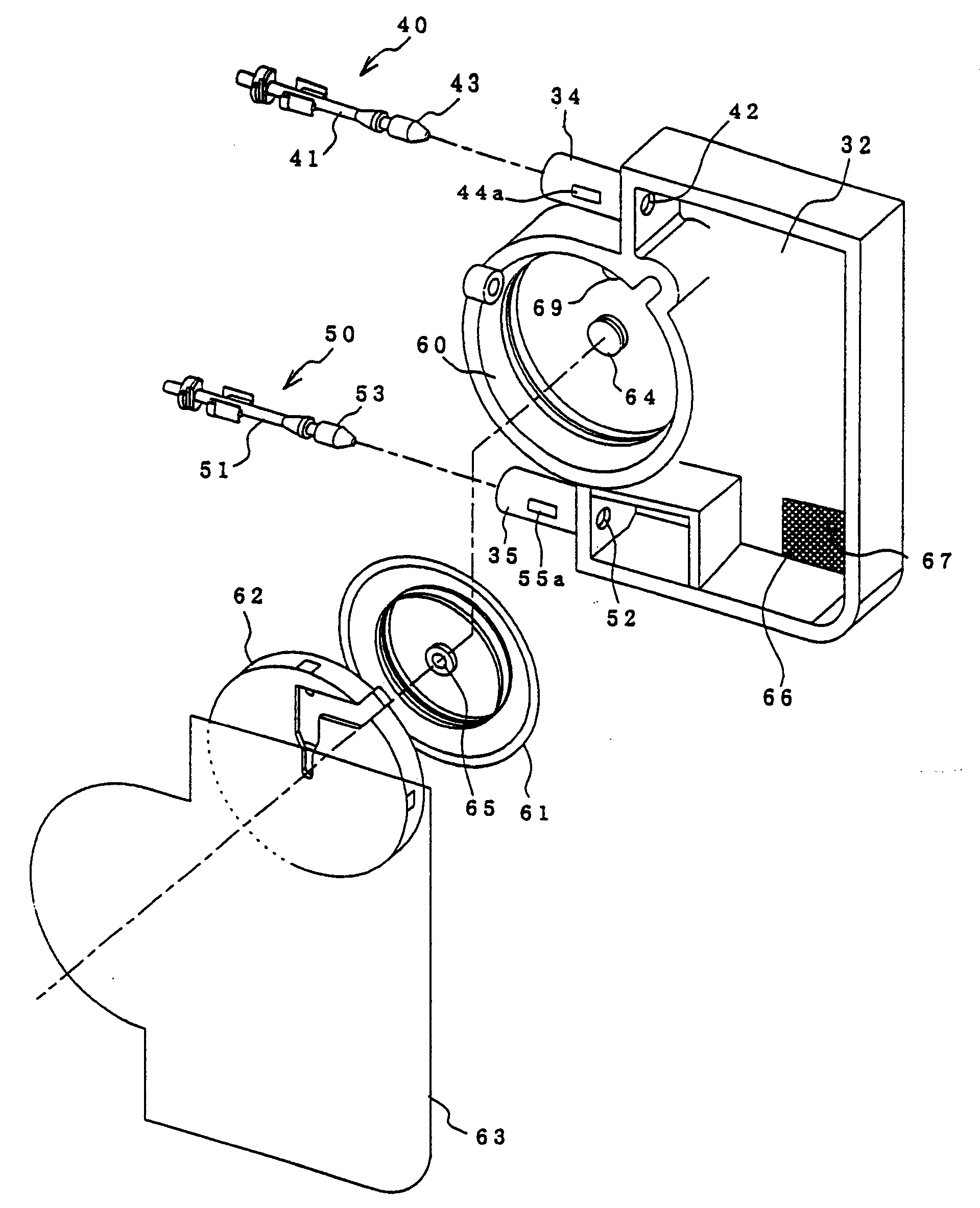
图4至图6分别示出本发明墨盒的一实施例。墨盒31的一侧上形成沿上下方向延伸的墨水贮存室32,而另在一侧上形成后述的负压发生系统33。在墨水贮存室32的上部及下部分别形成由筒状体构成的大气连通用连接口34和墨水供给用连接口35。上述两连接口34、35实现与外部的连接。4 to 6 respectively show an embodiment of the ink cartridge of the present invention. An
在各连接口34、35上,因在其圆周面上分别形成连通用的窗34a、35a,阀体40、50可沿轴向移动地容纳在内部。各阀体40、50按如下方式插入连接口34、35内,即在阀闭合状态下,将密封开口42、52(开口42、52与连接口34、35连通)的由弹性体构成的密封圈43、53嵌装在一端41a、51a从连接口34、35突出的滑动轴41、51的另端侧上,并利用弹簧44、54把密封圈43、53弹压在开口42、52上。In each of the connecting
当利用这样的构成,把墨盒31装到后述的连接组件80上时,大气连通用连接口34及墨水供给用连接口35全部维持在开放状态,均可向打印头供墨。With such a configuration, when the
负压发生系统33的构成如图6所示,把膜阀61及兼有固定膜阀61的外周的固定件的流路形成部件62容纳在与墨水贮存室32连通的断面为圆形的凹状阀室60内,用具备隔气性的膜63将包含墨水贮存室32的区域封住。在阀室60的中心形成凸部64,而在膜阀61上,对着凸部64的位置上,形成贯通孔65。The structure of the negative
图7a,图7b分别清楚地示出内外两侧形成在负压发生系统33上的墨水流路,按如下方式连通:从墨水贮存室32流入过滤网66的墨流①,从通孔67经流路68流入阀室60的通孔69的墨流②,通过膜阀61的墨流③,经过流路73(该流路73连结阀室60的通孔70和通孔71、72)的墨流④以及经过流路75的墨流⑤,流路75连接通孔74和通孔72,而通孔74与墨水供给用连接口35连通。Fig. 7 a, Fig. 7 b clearly show the ink flow path that is formed on the negative
图8示出负压发生系统33的断面构造。膜阀61被形成为周围壁厚的隔膜,因弹簧77的作用贯通孔65被凸部64弹性地顶着。该弹簧77的弹力应该设定为墨水对打印头的压力能够维持负压,且随着打印动作的进行可供给墨水的程度。FIG. 8 shows a cross-sectional structure of the negative
图9示出设置在打印机主体上的连接组件80的一个实施例。在具有与墨盒31的前面和底面形状相一致的壁81、82的主体83上分别形成凹部84、85,凹部84、85容纳墨盒31的大气连通用连接口34、墨水供给用连接口35,并分别使阀体40、50后退后,打开阀。Figure 9 shows one embodiment of a
与大气连通用连接口34啮合的凹部84经形成在主体表面上的毛细管87与大气相通,而凹部85经通孔88与打印头89连通。The
对于这种构成,当如图10所示地把充填了墨水的墨盒以各连接口34、35插入连接组件80的凹部84、85内时,阀体40、50顶推凹部84、85的壁84a、85a,阀被打开。由此,墨盒31的墨水贮存室32经毛细管87与大气相通,墨水贮存室32内的墨水从连通孔88供给到打印头89。For this configuration, when the ink cartridges filled with ink are inserted into the
当因印刷墨水被打印头89消耗,墨水供给用连接口35的负压增大时,因为膜阀61的内外压差增大,所以承受墨水贮存室32的墨水压力的膜阀61抵抗弹簧77的弹力脱离凸部64。因此,膜阀61的贯通孔65打开,通孔69和通孔72连通,墨水流向墨水供给用连接口35。When the negative pressure of the ink
当墨水流入打印头89内,墨水供给用连接口35的负压降低时,膜阀61在弹簧77的弹力作用下顶紧在凸部64上,贯通孔65被凸部64闭合。以后,为了使墨水供给用连接口35的墨水负压保持一定,膜阀61相对于凸部64反复地接离。When the ink flows into the
另一方面,当因变更印刷模式而将应该更换的墨盒从连接组件80上取下时,因各口34、35的阀体40、50失去支承后,由弹簧44、54关闭,墨水贮存室32与大气的连通被切断,所以即使在作用过程中从打印机上取下墨盒的状态下,可防止墨水的泄漏和墨水溶液的挥发,可长期保存。On the other hand, when the ink cartridge that should be replaced is removed from the
当大气连通用连接口34内的滑动轴41的前端41a在比墨水供给用连接口35的滑动轴51的前端51a相对早一点受到凹部84的壁的顶推,即前端41a比前端51a长一些地构成,或者在壁84a上形成突起等时,就能够防止墨水室和大气的压差造成的不利影响,即墨水的泄漏和大气经打印头89吸入。When the front end 41a of the
图11、图12分别示出本发明墨盒31′的另一实施例。在本实施例中,墨水供给用连接口35′是单纯的开口。在本例中,在墨盒31′被装到连接组件80′上之前,由于大气连通用连接口34的阀体40在弹簧44的弹力作用下维持阀关闭状态,而负压发生系统33的膜阀61也维持阀关闭状态,因此,墨水贮存室32内的墨水不会从墨水供给用连接口35′处泄漏出。Fig. 11 and Fig. 12 respectively show another embodiment of the ink cartridge 31' of the present invention. In this embodiment, the ink supply connection port 35' is a simple opening. In this example, before the ink cartridge 31' is installed on the connection assembly 80', the
另一方面,如图13所示,连接组件80′上形成着凹部90,该凹部90具备与打印头89连通的通孔88,如图14所示,把墨盒31′装到组件80′上时,阀体40受到凹部84的壁84a的推压,阀开放。因此,墨盒31′的墨水贮存室32经毛细管87与大气连通,墨水贮存室32内的墨水从通孔88供给到打印头89内。On the other hand, as shown in Figure 13, a
在本例中,由于也由连接口34的阀体40和负压发生系统33隔断了墨水贮存室32与大气的连通,因此,在使用过程中,即使在从打印机上将其取下的状态下,仍能够防止墨水的泄漏和墨水溶液的挥发,可作长期保存。更好的是,用罩等部件将墨水供给用连接口35′封住,以防供给口35′附近附着的墨水干燥。In this example, since the
图15示出连接组件90的另一实施例。在具有与墨盒31的前面和底面形状相一致的壁91、92的主体93上分别形成凹部94、95,该凹部94、95容纳墨盒31的大气连通用连接口34、墨水供给用连接口35,并分别使阀体40、50后退后,打开阀。FIG. 15 shows another embodiment of a
与大气连通用连接口34啮合的凹部94经由形成在主体表面上的毛细管97延伸到打印头89,而凹部95经过通孔98与打印头89连通。A
打印头89具备:接受墨盒31供给的墨水,将由压力发生系统加压后的墨水以液滴方式排出的喷墨口100和与毛细管97的端部97a连通的大气开口102。The
对于这种构成,当如图16所示地将充满墨水的墨盒以各连接口34、35插入连接组件90的凹部94、95内时,阀体40、50受到凹部94、95的推压而把阀打开,墨水贮存室32内的墨水就可供给到打印头89。For this configuration, when the ink cartridge filled with ink is inserted into the
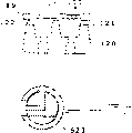
图17a示出封盖机构110的一例,由有选择地只封住打印头89上形成了喷墨口100的区域,且经开口111a与图未示出的吸墨泵连通的第1封盖111和同时封住喷墨口100和大气开放口102的第2封盖112构成。虽然上述第2封盖112具备凹部,该凹部构成密封空间,但如图17b所示,形成与喷口板101的喷墨口100和大气开放口102弹性接触,作为可封闭平台113的盖,也能起到同样的作用。Figure 17a shows an example of the capping mechanism 110, by selectively only sealing the area where the
如图18a所示,当用封盖机构110的第1封盖111盖住打印头89,并使打印头89产生负压时,因为极大的负压经打印头89作用于墨水供给用连接口35上,所以膜阀61打开,墨水贮存室32内的墨水流入打印头89内,墨水充填到打印头89内。As shown in Figure 18a, when the
在打印操作过程中,因喷墨口100的堵塞而造成印刷不佳时,与墨盒装填时一样,如图18a所示,把第1封盖101盖住打印头89,使打印头89内产生负压,则墨水从打印头89的喷墨口100处被强制排出,堵塞现象自然消失。During the printing operation, when the printing is not good due to the clogging of the
在印刷动作结束时,使打印头89移向封盖机构110的第2封盖112,封盖112封住了打印头89时,如图18b所示,因喷墨口100及大气开放口102都被封住,所以即使因打印机等的移动造成墨盒31倾斜,墨水到达大气连通用连接口34,并从大气开放口102处泄出,而泄出的墨水可容纳在封盖112,仍能防止墨水泄漏到打印机外。At the end of the printing operation, the
对于上述实施例,虽然采用各自不同的封盖封住打印头89上形成喷墨口100的区域和一起封住喷墨口100和大气开放口102的区域的构成,但也可如图19a,19b所示,在同一个封盖120上形成只封住形成喷墨口100的区域的凹部121和只封住大气开放口102的凹部122,使凹部121和凹部122分别经切换阀523与吸墨泵连通和与大气连通,在休止时如图19b所示,将凹部122与大气隔断,也能起到同样作用。然而,另外一个切换阀可设置在凹部121和吸墨泵之间。For the above-described embodiment, although adopting different caps to seal the area where the
图20,图21,图22分别示出本发明墨盒的另一实施例,在该实施例中,除了形成墨水注入用口和向打印头供给墨水的墨水口之外,其它方面与上述实施例一样。Fig. 20, Fig. 21, Fig. 22 show another embodiment of the ink cartridge of the present invention respectively, in this embodiment, except forming the ink injection port and the ink port that supplies ink to the printing head, other aspects are the same as the above-mentioned embodiment. Same.
也就是说,该墨盒130的一侧上形成向上下延伸的墨水贮存室32,在另一侧上形成负压发生系统33,在墨水贮存室32的上部及下部分别形成与外部进行连接的由筒状体构成的大气连通用连接口34和墨水注入用连接口131,在最下部上形成向打印头供给墨水的墨水口132。That is to say, an
对于大气连通用连接口34和墨水注入用连接口131,在其圆周面上形成连通用的窗34a、131a,阀体40、140可沿轴向移动地容纳在内部。各阀体40、140是按如下方式插入连接口34、131内,即在阀闭合状态下,将密封开口42、142(开口42、142与连接口34、131连通)的由弹性体构成的密封圈43、143嵌装在一端41a、141a从连接口34、131突出的滑动轴41、141的另端侧上,并利用弹簧44、144把密封圈43、143弹压在开口42、142上。The
当利用这样的构成,把墨盒装到后述的连接组件上时,大气连通用连接口34维持阀开放状态,而墨水注入用连接口131维持阀闭合状态,只在插入了墨水注入装置时阀才打开。When using such a structure, when the ink cartridge is mounted on the connection assembly described later, the air
负压发生系统33的构成如图22所示,把膜阀61及兼有固定膜阀61外周的固定件的流路形成部件62容纳在与墨水贮存室32连通的断面为圆形的凹状阀室60内,用具备隔气性的膜63将包含墨水贮存室32的区域封住。在阀室60的中心形成凸部64,而在膜阀61上,对着凸部64的位置上,形成贯通孔65。The structure of the negative
图23a,图23b分别清楚地示出内外两侧形成在负压发生系统33上的墨水流路。按如下方式连通:从墨水贮存室32流入过滤网66的墨流①,从通孔67经流路68流入阀室60的通孔69的墨流②,通过膜阀61的墨流③,经过流路73(该流路73连结阀室60的通孔70和通孔71、72)的墨流④以及经过流路75的墨流⑤,流路75连接通孔74和通孔72,而通孔74与墨水口132连通。符号133表示嵌入墨水口132内的密封圈。Fig. 23a and Fig. 23b clearly show the ink flow paths formed on the negative
图24a,图24b示出连接组件150的一个实施例。在具有与墨盒的前面和底面形状相一致的壁151、152的主体153上分别形成凹部154、贯通孔155和凹部156,它们容纳墨盒的大气连通用连接口34、墨水注入用连接口131以及墨水口132。Figures 24a, 24b show an embodiment of the
与大气连通用连接口34啮合的凹部154经形成在主体表面上的毛细管157与大气相通,在内部形成了推压大气连通孔的阀体的壁154a 。The
容纳墨水注入用连接口131的贯通孔155不具备与墨盒130的阀体140接触的壁,因而维持阀闭合状态。连接墨水口132的凹部156经连通孔158与打印头89连通。The through-
对于这种构成,如图25a所示,把墨水口132定位于凹部156内,嵌入到连接组件侧后,就把充填了墨水的墨盒连接到连接组件130上。With this configuration, as shown in FIG. 25a, after the
在把墨盒130装到连接组件150上前,由于膜阀61维持阀闭合状态,墨水贮存室32内墨水不会从墨水口132处泄漏出,而由于大气连通用连接口34的阀体40维持阀闭合状态,墨水贮存室32内的墨水也不会蒸发。Before the
在连接状态下,墨盒130的大气连通用连接口34的滑动轴41受壁推压抵抗弹簧44后退,则阀开启。因此,墨水贮存室32经毛细管157与大气连通。另外,墨水注入用连接口131的阀体20维持阀关闭状态,可阻止墨水泄漏和大气浸入。In the connected state, the sliding
在此状态下,当用封盖封住打印头89,并对打印头89产生负压时,因为墨水口132变为强负压,所以负压发生部33的膜阀61打开,墨水贮存室32内的墨水流入打印头89内,墨水充填到打印头89内。In this state, when the
另一方面,墨水被打印头89消耗,墨水口132的负压增大时,与前述实施例一样,向打印头89供给墨水。On the other hand, when the ink is consumed by the
也就是说,因为膜阀61的内外压差变大,所以受到墨水贮存室32内的墨水压力的膜阀61抵抗弹簧77的弹力而脱离凸部64。因此,膜阀61的贯通孔65被打开,通孔69和通孔42相通,墨水流入墨水口132内。当墨水流入打印头89内,墨水口132内的负压变小时,膜阀61在弹簧77弹力作用下受凸部64的推压后,贯通孔65被凸部64封闭。以后,为了保持墨水口132的墨水压力一定,膜阀61反复与凸部64接离。That is, since the pressure difference between the inside and the outside of the
如图25a和25b所示,当墨盒130中的墨水被消耗且需要再注满墨水时,再注满墨水的工具如注射器160,可被插入通孔155中,使注射器160的尖端按压阀件140,并使阀件140呈打开状态。如图25c所示,注射器160的尖端具有用于按压阀件140的按压部160a和用于将注射器160的内部和喷墨连接口131连通的连通部160b。因此,如果将注射器160插入通孔155直到按压部160a将阀件140推压成阀打开状态,注射器160的内部通过喷墨连接口131和开口142,可与墨水贮存室32的内部连通。如果注射器160的活塞161处于被推压状态,则注射器160中的墨水通过连通部(口)160b、喷墨连接口131和开口142被装入墨水贮存室32中,同时与再填充墨水结合的、压缩在墨水贮存室32中的空气,通过大气连通用连接口34和毛细管157,由墨水贮存室32被排放到大气中。As shown in Figures 25a and 25b, when the ink in the
当预定数量的墨水被再填充入墨水贮存室32中后,注射器160被拆下,阀件140在弹簧144的偏压力的作用下被移动并呈关闭状态。因此,可以阻止墨水的泄漏。After a predetermined amount of ink has been refilled into the
另外,虽然利用上述实施例可简单地再填充墨水,但也可以使用下面的方法,即:将空注射器160插入凹部155以收集在贮存室32中剩余的所有墨水,然后,用注射器160将一预定量的墨水再注满贮存室32。该方法有利于精确地处理与打印数量有关的墨水的消耗和判断墨水的剩余量。In addition, although the ink can be refilled simply by utilizing the above-described embodiment, it is also possible to use a method in which an
图26a,图26b,图27分别示出本发明墨盒一实施例的内外构造。墨盒170是由具备向一侧面开口的凹部172、平行于该开口面的上部和向插入方向突出的导向部173、174的基体175以及封住该凹部172的薄膜176形成墨水贮存室177而构成的。薄膜176随着承受墨水压力的变动而可变形,且选择用具备隔气性和粘着性的材料制作。Fig. 26a, Fig. 26b, Fig. 27 respectively show the internal and external structure of an embodiment of the ink cartridge of the present invention. The
当被安装到打印机上时,在成为下部的位置上形成装填了后述阀门机构的墨水供给口178,而在上部形成后述的大气连通用连接口179。在构成凹部172底部的基体175的表面上形成蛇形细槽180,该蛇形细槽180的一端180a向基体175侧面开孔,而另一端180b与大直径凹部181连接。When mounted on a printer, an
如图26b所示,在凹部181上形成有若干直径变细的凹槽181a,把对墨水具有疏水性的通气性薄膜181c粘贴或溶合在其上,隔离了成为集墨器的大直径凹槽181a。通气性薄膜181c可由氟化树脂的多孔薄膜构成,最好比打印头的喷墨口的墨水保持力高,具备3000至5000Pa以上的疏水性。As shown in Figure 26b, a number of
用具备通气性粘接性的薄膜182封住这些细槽180及凹部181的露出面后,这些细槽180就构成了毛细管,而凹部181构成集墨器。After sealing the exposed surfaces of these
该凹部181经过连接用凹部184连接到连通室183上,该连通室183形成在大气连通用连接口179的附近。连接用凹部184和连通室183的截面尺寸应按如下方式形成,即至少墨水因毛细管张力的作用不会到达凹部181,而且最好能够确保即使墨水流入凹部181,也会因与墨水贮存室177(凹部172)的墨水液面的水头差而返回到连通室183的间隙。The
图28示出上述墨盒170的断面构造。在墨水供给口178上形成了具有截头圆锥形弹簧承受部185并以此为中心的筒状部186,阀体188可移动地嵌入在墨水供给口178内,且被套在弹簧承受部185上的螺旋弹簧187推向墨水供给口侧,与密封圈189常时地弹性接触。前述密封圈189兼作防脱出部件而被嵌装在墨水供给口侧。在阀体188受到弹簧承受部185推压的状态下,在该筒状部186上穿设与墨水贮存室177连通的通孔190(参照图27)。FIG. 28 shows a cross-sectional structure of the
如图29a所示,阀体188形成在筒状部186内表面滑动的筒状体188a和在其中内部上的隔壁188b,来自打印头侧的动作杆和弹簧承部185与隔壁188b可接触地构成。As shown in Figure 29a, the
另一方面,在大气连通用连接口179上形成了筒状部193,该筒状部193经开口191(参照图27)与连通室183连通,而借助于贯通孔192与墨水贮存室177的上部连通,阀体195嵌装到连接口179内,该阀体195受到弹簧194向外的弹力,在开口侧嵌装兼作防脱部件的密封圈200。On the other hand, a cylindrical portion 193 is formed on the
阀体195如图29b所示由可插入开口192内的动作杆196,受压部件197和密封部件198构成。将密封部件198嵌入动作杆196的大直径部196a上形成的环状凹部196b内,使细直径部196c从墨水贮存室侧穿过开口192,把弹簧194嵌入细直径部196c后,通过把受压部件197固定到细直径部的前端上而组装完毕。The
若使开口192的内径比大直径部196的外径大,且比密封部件198的外径小,则在动作杆196穿过开口192的状态下,将密封部件198嵌装到墨水室侧,而使弹簧194从大气连通用连接口179侧穿过,同样也能固定受压部件197。If the inner diameter of the opening 192 is larger than the outer diameter of the large-
图30和图31示出适合于上述墨盒的连接组件的一实施例。该连接组件201的构成是与墨盒170连接后,贮墨室202的上部空间与大气连通,而从下部接受墨水的供给,从下部的墨水流出口203将墨水向打印头排出。Figures 30 and 31 show an embodiment of a connection assembly suitable for the ink cartridge described above. The structure of the
在与墨盒的墨水供给口178及大气连通用连接口179对应原位置上分别形成前端部有墨水流入用凹槽204a,大气流入用凹槽205a的墨水流入管204,大气连通管205,然后经构成连接组件201的壳体206的通孔206a,206b与贮墨室202连通,并装填与前述阀体195基本相同的阀体207、208。On the original position corresponding to the
在本实施例中,为了能够使贮墨室202内的墨水相对于打印头维持一定负压供给,设置了把膜阀209、流路形成部件210组装到凹部211内,用高隔气性的薄膜212封住其外侧而构成的负压发生室。In this embodiment, in order to maintain a certain negative pressure supply of the ink in the
在本例中,在墨盒170未装到打印机上时,墨水供给口178的通孔190及大气连通用连接口179的开口192分别被阀体188、195封止,墨水贮存室177与大气隔断。而连接组件201也被阀体207、208封住,如图31和图34a所示。In this example, when the
另一方面,当把墨盒170装到连接组件201上时,在该过程中,墨水流入管204及大气连通管205嵌合墨水供给口178及大气连通用连接口179的密封圈189、200并移动,在不受弹簧187、194的弹力和墨水固化而引起的固着等影响下由其前端将阀188的隔板188b及受压部件197推压移动到规定的位置上,如图32,33a,33b所示。On the other hand, when the
因此,与墨水贮存室连通的通孔190被打开,而密封部件198脱离开口192,筒状部193及墨水贮存室177经凹部181及细槽180与大气连通。Therefore, the through
为了使大气连通管205及大气连通用连接口179的接合位置,更详细地说,开阀时期比由墨水供给口178和墨水流入管204造成的阀体188的开阀时期早,应分别设定各自的相对位置,就能够防止墨盒170安装时的墨水泄漏。In order to make the connecting position of the
也就是说,因墨水贮存室177内的空气膨胀,气压比大气压高时,在将墨水供给口178的阀体188维持在闭合状态下,只要打开大气连通连接口179的阀体196,就能够使墨水贮存室177内的空气选出到外部。采用这样的手段,在连续地打开墨水供给口178时,因墨水维持在大气压下,所以能够防止墨水从墨水供给口178泄漏出。That is to say, when the air pressure in the
当然,因在该状态下,连接组件201的阀体207、208都分别被打开,所以如图34b所示,墨水贮存室177内的墨水可经过连接组件201从墨水口203供给到打印头。在此状态下,因墨盒170的墨水贮存室177及连接组件201的贮墨室202经由槽180及薄膜182形成的毛细管与大气连通,所以能够向打印头89可靠地供给必要的墨水量,并可有效地防止这些室177及202的墨水溶液蒸汽挥发到大气中。Of course, in this state, the
另一方面,因打印机的移动等原因,墨盒170的姿态发生大的变化时,墨水会到达上部开口192,并从开口192处泄漏到连通室183。因为这些墨水流入凹部184内并溜存在凹部181的大空间内,且凹部181被通气膜181c分割开了,所以即使将打印机移动或保管时倒立,仍可防止流到细槽180而漏出到外部类的事发生。On the other hand, when the posture of the
此外,当通气膜181c具备比打印头89的喷墨口的凹(凸)液面的墨水保持力高的疏水性时,至少在墨水贮存室177因空气膨胀而压力增高的情况下,仍能够防止墨水从打印头侧流出从墨盒170漏出。另外,即使如墨水从打印头的喷墨口处流出,通常,因由为防止喷墨口堵塞而设的封盖封住,所以墨水不会污染打印机。In addition, when the air-
甚至已流入到凹部181内的墨水当墨盒170恢复到原来正规的姿态时,因间隙增大,流向无毛细管张力的凹部184内,并因重力而移动到连通室183内,最后从开口192返回墨水贮存室177。Even the ink that has flowed into the
当打印头消耗着墨水时,因墨水收集在由形成在墨水贮存室177底部上的凹部所形成的小室177a内,墨水液位被维持在高于通孔190上方,至最后能够将墨水供给打印头89。When the print head consumes ink, because the ink is collected in the small chamber 177a formed by the recess formed on the bottom of the
另一方面,在随着印刷介质的更换而更换墨盒170的情况下,从连接组件201取下墨盒170时,因为墨水流入管204及大气连通管205被拔出,所以墨水供给口178及大气连通用连接口179的阀体188及阀体195被弹簧187、204推回,从而封住了与墨水贮存室177连通的通孔190及开口192,可防止墨水贮存室177的墨水和墨水溶液的泄漏以及挥发。On the other hand, when the
在上述实施例中,说明了把具备负压发生系统的连接组件201安装到打印头上的情况,但在打印头的喷墨口的凹(凸)液面的墨水保持力高时,很清楚不必经构成负压发生系统的压差阀机构就能连接。In the above-mentioned embodiments, the case where the
图35a,35b,35c示出连接组件的另一实施例。连接组件201在一侧具备向上下方向延伸的贮墨室202,在贮墨室202上部及下部分别形成筒状大气连通用连接口205和墨水流入用连接口204,连接口205实现与外部的连接。而在最下部上形成与打印头89连通的墨水流出口203。Figures 35a, 35b, 35c show another embodiment of a connection assembly. The
各连接口204、205上,在其圆周面上形成了连通用的窗204a,205a,阀体207、208可沿轴向移动地插入在内部。该阀体207、208容纳在上述连接口204、205内,而各自的滑动轴220、230的一端220a,230a露出连接口204、205。In the respective connecting
各阀体207、208按以下方式插入连接口204、205内,即把由弹性体构成的用于封住连通连接口204、205的墨水贮存室开口204b,205b的密封圈222、232嵌装到滑动轴220、230的另一端侧上,并以如前所述的方式由弹簧使密封圈222、232弹性接触开口204b、205b。Each valve body 207,208 is inserted in the connection port 204,205 in the following manner, promptly the sealing ring 222,232 that is used to seal the ink
下面以墨水流入连接口204为例详细地说明这些阀机构。These valve mechanisms will be described in detail below taking the ink
如图35b所示,筒状连接口204具备略为四角形开口窗204a,该开口204a中心线方向的长为L1,宽为W1。阀体207的直径应该是相对于其滑动轴220的滑动维持足够的强度,且不妨碍墨水的流动,在受弹簧顶紧的状态下于对着窗204a的区域上,用兼作弹簧座的筋条224固定着能够堵住窗204a的长度为L2,宽度为W2的截面为圆弧形封闭部223。As shown in FIG. 35 b , the
在封闭部223被弹簧顶紧状态下的停止位置侧(图中左侧)形成了防脱部223a,该防脱部223a可移动地与墨水流入用连接口204的窗204a啮合。图中符号225、235表示具备穿插滑动轴220、230的贯通孔225a、235a的,可移动地支承滑动轴220、230一端220a、230a侧的固定件。On the stop position side (the left side in the figure) of the closing
当把前述的图28所示构造的墨盒170装到这样构成的连接组件201上时,连接组件201的滑动轴220、230被逆着弹簧推压,各自的密封圈222、232朝贮墨室202侧移动,开口204b、205b被打开,同样地,墨盒170的阀体188、196(参照图32)也被开放。因此,如前所述,墨盒内的墨水流入连接组件201内,可向打印头供给墨水。When the
另一方面,当因为墨盒170内的墨水被消耗贻尽,或需要更换墨水而把墨盒170从连接组件201上取下时,连接组件201及墨盒170的滑动轴220、230和阀体188、196都失去支承而被弹簧的弹力打开。On the other hand, when
由此,连接组件201的大气连通用连接口205及墨水流入用连接口204被隔断,从而防止了墨水溶液从大气连通用连接口205处挥发或墨水从墨水流入用连接口204处流出。Thus, the
在墨盒170被拉出的状态下,连接组件201的墨水流入用连接口204成为暴露于大气的状态,如图36a所示,附着在窗204a上的墨水K的溶液挥发,墨水固化。当在此状态下,再次把墨盒170装上时,如图36b所示,连接组件201及墨盒170的滑动轴220、230被朝图中箭头A方向推回,在其移动过程中,防脱部223a在窗204a内移动,除去了固化于窗204a上的墨水K。In the state where the
因此,在装着墨盒170的状态下,窗204a正常状态下为开口状,墨水从墨盒170流入连接组件201内。Therefore, when the
图37a,37b,37c,37d详细示出上述墨盒170和连接组件201的墨水流路。墨盒170(图37a)内的墨水正被消耗着,如图37b所示,墨水液面下降到连接组件201的贮墨室202上的狭部202a前,贮墨室202内的墨水的液面在狭部202a的毛细管张力作用下被狭部202a所维持。37a, 37b, 37c, 37d show the ink flow paths of the
另一方面,当对应于因打印头的墨水消耗造成的负压,膜阀61被打开时,由于负压作用于墨盒170上,因此,墨盒170内的墨水经负压发生部33流入打印头。On the other hand, when the
把贮墨室202的墨水的液面维持在过滤网66、最好为通孔67上方的液面H高度处,且将墨盒170的墨水供给打印头(图37c),在更换困难的连接组件内,不会出现断墨水的现象,并将墨盒170内的墨水全部排出到打印头(图37d)。The liquid level of the ink in the
在上述实施例中,由狭部的毛细管张力维持贮墨室202的最低墨水液面高度H,而如图38a至图38d所示,若将截面为圆形的浮子240插入贮墨室202上部,则能够在不依赖于狭部202a的毛细管张力的情况下将墨水维持在规定的液面高度。In the above-mentioned embodiments, the minimum ink liquid level H of the
也就是说,在存在如图38a所示的规定量墨水的状态下,由于浮子240位于狭部202a上方的位置,不会妨碍墨水的排出。当墨水液面低于应该维持的高度H下,浮子240由狭部202a阻止下降,产生毛细管张力,与前述的情况一样,贮墨室202内的墨水液面仍维持在液面高度H(图38b和图38c),而与墨盒170内的墨水被消耗的情况无关。因而,维持着该状态,将墨盒170内的墨水一直供给到打印头(图38d)。That is, in a state where a predetermined amount of ink exists as shown in FIG. 38a, since the
在实施例中,说明了把墨盒170直接安装到连接组件201上的情况,如图39所示,把液面传感器241安装在连接组件201的贮墨室202的液面应该维持的高度上,经受液面传感器241控制的送液泵242并利用管243与墨水袋等的墨水贮存室244的墨水流出口245连接,也能起到同样的作用。在此情况下,最好在贮墨室202的上部形成大气连通用的开口246,并用具备疏水性和通气性的膜247将该开口封住。In the embodiment, the situation that the
图40示出适用上述墨盒170及连接组件201的喷墨打印机的一个实施例。印刷机构或后述的容纳墨盒更换机构的壳体251是可用盖板252开关上面而构成的,在前面251a的操作方便的一侧附近设有墨盒拔插用的窗253和墨盒推出用的柄254。在壳体251的背面上设纸架255,而在前面下部上设排纸托256。FIG. 40 shows an embodiment of an inkjet printer to which the above-mentioned
图41a,41b,41c分别示出上述墨盒更换机构的一实施例。柄254受转动支点257支承,由导向轴258引导作往返运动,一个臂261固定在其上,该臂261延伸到设置了打印头259的托架260的背面前,其前端与导向轴258平行。打印头259连接在前述的如图30所示的连接组件201上,经连接组件201接受来自墨盒的墨水供给。在臂261上,与拔插用窗253对应的位置上,设推压片263,该推压片263由与相邻近的墨盒262不接触的那样宽的滚子构成。Figures 41a, 41b, and 41c respectively show an embodiment of the ink cartridge replacement mechanism described above. The
采用上述的构成,如图41c所示,当压下柄254时(图中箭头B方向),推压片263向前面侧移动,只选择对着窗253的墨盒并使其向前面侧移动(图中箭头C)。因此,解除了墨盒与打印头89的啮合,并可从窗253处将墨盒取出。Adopt above-mentioned constitution, as shown in Figure 41c, when depressing handle 254 (arrow B direction among the figure), pushing
因为推压片263由可转动的滚构成,所以能够防止柄254的转动引起的无用的外力,对垂直方向、即对墨盒的拉出不必要的方向的力对墨盒、托架260的作用。Because the pushing
当解除了柄254的推压力时,由复原部件264使柄254向上方移动,推压片263退回到原来的位置(图41b)。When the pushing force of the
图42a、图42b分别示出适合于上述相同打印机的墨盒的一个实施例。由于构造基本与上述的墨盒170的相同,因此,只考虑墨盒的拔插的操作性,在里侧的导向部173的基础上在另一端侧形成把持部175a。Figures 42a, 42b each show an embodiment of an ink cartridge suitable for the same printer described above. Since the structure is basically the same as that of the
在本实施例中,在墨盒170的墨水被消耗的阶段,通过面板270等指定该墨盒时,托架260将所指定的墨盒170移动到对应于壳体251的墨盒拔插用的窗253的位置上。In this embodiment, when the
在此状态下,若压柄254,则推压片263移动到前面侧上,推动从连接组件201向背面侧突出的导向部173,且墨盒170的大气连通孔及墨水供给口从连接组件201上脱出。在此状态下,用手指拉住把持部175a时,就能从连接组件201中将墨盒170拔出。当然,因所有阀体25、26、48、49处于关闭状态,所以在拉出墨盒之际,还能够抑制墨水从墨盒170的墨水供给口178处泄漏和连接组件201的墨水溶液的蒸发。In this state, if the
在此状态下,当把新的墨盒170从窗253处推到里侧时,墨盒170的大气连通孔179及墨水供给口178进入连接组件201的筒状大气连通口205及墨水供给口204内,这些口179、178、205、204的阀体198、188、208、207相互后退,将阀打开,墨盒的墨水贮存室177的上部及连接组件201的墨水室202的上部经由细槽180形成的毛细管与大气连通,墨盒170内的墨水流入连接组件201内。In this state, when a
在本发明中,说明了通过水平移动墨盒实现墨盒的插拔,如果是与托架的移动方向为非平行的方向,例如垂直方向上移动,因能够防止拔插动作造成的夹纸辊的移动,所以能够根据壳体构造作合适的选择。In the present invention, it is described that the insertion and removal of the ink cartridge is realized by moving the ink cartridge horizontally. If it is in a non-parallel direction with the moving direction of the carriage, for example, moving in the vertical direction, the movement of the pinch roller caused by the plugging and unplugging action can be prevented. , so an appropriate choice can be made according to the shell structure.
对于上述实施例中,虽然在壳体侧上形成墨盒拔插用的窗253,但若形成在盖体252上,因在墨盒更换时,不必打开盖体,所以也能起到同样的作用。In the above-described embodiment, although the
此外,在上述实施例中,说明了用手动操作实现墨盒的拔插,不过用电磁螺线管等电磁驱动装置也可起到同样的效果。In addition, in the above-mentioned embodiment, it has been described that the removal and insertion of the ink cartridge is achieved by manual operation, but the same effect can also be achieved by using an electromagnetic driving device such as an electromagnetic solenoid.
Claims (13)
Applications Claiming Priority (24)
| Application Number | Priority Date | Filing Date | Title |
|---|---|---|---|
| JP037410/2000 | 2000-02-16 | ||
| JP2000037410A JP2001225480A (en) | 2000-02-16 | 2000-02-16 | ink cartridge |
| JP037410/00 | 2000-02-16 | ||
| JP086007/00 | 2000-03-27 | ||
| JP2000085989A JP3772959B2 (en) | 2000-03-27 | 2000-03-27 | Connection unit for inkjet recording apparatus |
| JP085791/00 | 2000-03-27 | ||
| JP2000086007A JP3791294B2 (en) | 2000-03-27 | 2000-03-27 | Inkjet recording device connection unit |
| JP085791/2000 | 2000-03-27 | ||
| JP085989/2000 | 2000-03-27 | ||
| JP2000085791A JP3879809B2 (en) | 2000-03-27 | 2000-03-27 | Inkjet recording device |
| JP086007/2000 | 2000-03-27 | ||
| JP085989/00 | 2000-03-27 | ||
| JP2000092802 | 2000-03-30 | ||
| JP092802/2000 | 2000-03-30 | ||
| JP092802/00 | 2000-03-30 | ||
| JP228542/00 | 2000-07-28 | ||
| JP229167/2000 | 2000-07-28 | ||
| JP229166/2000 | 2000-07-28 | ||
| JP229167/00 | 2000-07-28 | ||
| JP2000229167 | 2000-07-28 | ||
| JP228542/2000 | 2000-07-28 | ||
| JP2000228542 | 2000-07-28 | ||
| JP229166/00 | 2000-07-28 | ||
| JP2000229166 | 2000-07-28 |
Related Parent Applications (1)
| Application Number | Title | Priority Date | Filing Date |
|---|---|---|---|
| CNB011039302A Division CN1184076C (en) | 2000-02-16 | 2001-02-15 | Ink cartridges for inkjet printers |
Publications (2)
| Publication Number | Publication Date |
|---|---|
| CN1496846A CN1496846A (en) | 2004-05-19 |
| CN1280103C true CN1280103C (en) | 2006-10-18 |
Family
ID=27573687
Family Applications (2)
| Application Number | Title | Priority Date | Filing Date |
|---|---|---|---|
| CNB2003101023498A Expired - Fee Related CN1280103C (en) | 2000-02-16 | 2001-02-15 | Cartriage and connecting assembly for ink-jet printer and ink-jet printer |
| CNB011039302A Expired - Fee Related CN1184076C (en) | 2000-02-16 | 2001-02-15 | Ink cartridges for inkjet printers |
Family Applications After (1)
| Application Number | Title | Priority Date | Filing Date |
|---|---|---|---|
| CNB011039302A Expired - Fee Related CN1184076C (en) | 2000-02-16 | 2001-02-15 | Ink cartridges for inkjet printers |
Country Status (8)
| Country | Link |
|---|---|
| US (10) | US6585358B2 (en) |
| EP (4) | EP2149453B1 (en) |
| KR (1) | KR100388332B1 (en) |
| CN (2) | CN1280103C (en) |
| AT (2) | ATE359180T1 (en) |
| DE (1) | DE60127740T2 (en) |
| ES (1) | ES2283350T3 (en) |
| PT (1) | PT1125747E (en) |
Families Citing this family (110)
| Publication number | Priority date | Publication date | Assignee | Title |
|---|---|---|---|---|
| JP3582592B2 (en) * | 2001-04-03 | 2004-10-27 | セイコーエプソン株式会社 | Ink cartridge and inkjet recording device |
| JPH08174860A (en) | 1994-10-26 | 1996-07-09 | Seiko Epson Corp | Ink cartridge for inkjet printer |
| JP3750138B2 (en) | 1996-02-21 | 2006-03-01 | セイコーエプソン株式会社 | Ink cartridge |
| JP4141523B2 (en) | 1997-03-19 | 2008-08-27 | セイコーエプソン株式会社 | Ink supply flow path valve device |
| ES2358054T3 (en) * | 1998-07-15 | 2011-05-05 | Seiko Epson Corporation | INK SUPPLY UNIT. |
| CN1280103C (en) * | 2000-02-16 | 2006-10-18 | 精工爱普生株式会社 | Cartriage and connecting assembly for ink-jet printer and ink-jet printer |
| US6935730B2 (en) * | 2000-04-03 | 2005-08-30 | Unicorn Image Products Co. Ltd. Of Zhuhai | One-way valve, valve unit assembly, and ink cartridge using the same |
| WO2002004217A1 (en) * | 2000-07-07 | 2002-01-17 | Seiko Epson Corporation | Ink feed unit for ink jet recorder and diaphragm valve |
| US20050243147A1 (en) * | 2000-10-12 | 2005-11-03 | Unicorn Image Products Co. Ltd. | Ink cartridge having bellows valve, ink filling method and apparatus used thereof |
| CA2359434C (en) * | 2000-10-20 | 2005-05-03 | Seiko Epson Corporation | Ink-jet recording device and ink cartridge |
| EP1481808B1 (en) * | 2000-10-20 | 2006-12-13 | Seiko Epson Corporation | Ink cartridge |
| EP1972453B1 (en) | 2000-10-20 | 2010-03-17 | Seiko Epson Corporation | Ink cartridge for ink jet recording device |
| JP4193435B2 (en) * | 2002-07-23 | 2008-12-10 | ブラザー工業株式会社 | Ink cartridge and ink filling method thereof |
| DE60221182T2 (en) * | 2001-05-17 | 2008-03-20 | Seiko Epson Corp. | Ink cartridge and method of manufacturing an ink cartridge |
| CN2602931Y (en) * | 2001-05-17 | 2004-02-11 | 精工爱普生株式会社 | Ink cartridge |
| CN100562431C (en) * | 2001-11-12 | 2009-11-25 | 精工爱普生株式会社 | Liquid ejection apparatus |
| US7156507B2 (en) * | 2001-11-12 | 2007-01-02 | Seiko Epson Corporation | Liquid injector |
| US7278718B2 (en) * | 2002-01-22 | 2007-10-09 | Seiko Epson Corporation | Liquid injecting apparatus |
| US7147310B2 (en) * | 2002-01-30 | 2006-12-12 | Hewlett-Packard Development Company, L.P. | Printing-fluid container |
| JP3772859B2 (en) * | 2002-07-09 | 2006-05-10 | セイコーエプソン株式会社 | Ink cartridge and ink cartridge decompression package |
| US7025445B2 (en) * | 2002-07-19 | 2006-04-11 | Hewlett-Packard Development Company, L.P. | Gas actuated ink line valve |
| JP3991853B2 (en) * | 2002-09-12 | 2007-10-17 | セイコーエプソン株式会社 | ink cartridge |
| ATE393009T1 (en) | 2002-11-12 | 2008-05-15 | Objet Geometries Ltd | METHOD AND SYSTEM FOR PRINTING A THREE-DIMENSIONAL OBJECT |
| US6984030B2 (en) * | 2002-11-13 | 2006-01-10 | Seiko Epson Corporation | Ink cartridge and method of regulating fluid flow |
| JP4457591B2 (en) * | 2002-12-13 | 2010-04-28 | セイコーエプソン株式会社 | Differential pressure valve unit, liquid cartridge, and liquid cartridge assembling method |
| KR100487585B1 (en) * | 2002-12-20 | 2005-05-03 | 주식회사 프린톤 | Method of refilling ink in an ink cartridge for an inkjet printer |
| US6951387B2 (en) * | 2003-01-15 | 2005-10-04 | Xerox Corporation | Ink tank with capillary member |
| CA2745944C (en) * | 2003-03-26 | 2012-07-31 | Seiko Epson Corporation | Liquid container |
| JP2004314600A (en) * | 2003-04-04 | 2004-11-11 | Canon Inc | Liquid storage container, liquid using device and recording device, and inkjet cartridge |
| JP2004338383A (en) * | 2003-04-25 | 2004-12-02 | Canon Inc | Ink cartridge, recording apparatus equipped with the ink cartridge, and method of manufacturing the ink tank |
| JP2004330470A (en) * | 2003-05-01 | 2004-11-25 | Seiko Epson Corp | Liquid supply device and recording device |
| JP3848295B2 (en) * | 2003-05-16 | 2006-11-22 | キヤノン株式会社 | Ink tank |
| US6837577B1 (en) * | 2003-06-18 | 2005-01-04 | Lexmark International, Inc. | Ink source regulator for an inkjet printer |
| JP4337500B2 (en) * | 2003-10-24 | 2009-09-30 | ソニー株式会社 | Liquid ejection device |
| US7448734B2 (en) * | 2004-01-21 | 2008-11-11 | Silverbrook Research Pty Ltd | Inkjet printer cartridge with pagewidth printhead |
| US7188937B2 (en) * | 2004-01-29 | 2007-03-13 | Hewlett-Packard Development Company, L.P. | Printing-fluid venting assembly |
| CN100471678C (en) * | 2004-02-03 | 2009-03-25 | 精工爱普生株式会社 | Pressure control valve unit and liquid injection device |
| JP4496806B2 (en) * | 2004-03-04 | 2010-07-07 | ブラザー工業株式会社 | Inkjet recording device |
| JP4321370B2 (en) * | 2004-06-14 | 2009-08-26 | ブラザー工業株式会社 | Ink filling method |
| CN2744512Y (en) * | 2004-06-15 | 2005-12-07 | 珠海纳思达电子科技有限公司 | Self-contained integrated printer print cartridges with ink bag |
| JP2006088403A (en) * | 2004-09-21 | 2006-04-06 | Fuji Xerox Co Ltd | Inkjet recording device |
| BRPI0506191A (en) * | 2004-11-29 | 2006-07-25 | Seiko Epson Corp | cartridge refill process, liquid refill device and cartridge refill |
| JP2006188312A (en) * | 2005-01-04 | 2006-07-20 | Funai Electric Co Ltd | Printer |
| JP4696613B2 (en) * | 2005-03-16 | 2011-06-08 | ブラザー工業株式会社 | ink cartridge |
| US20070091128A1 (en) * | 2005-06-09 | 2007-04-26 | Junzhong Wu | Ink cartridge for printer |
| DE102005029588A1 (en) | 2005-06-25 | 2007-01-04 | Artech Gmbh Design + Production In Plastic | ink cartridge |
| CN2832528Y (en) * | 2005-08-02 | 2006-11-01 | 珠海纳思达电子科技有限公司 | Ink cartridge for ink-jet printer |
| US7669991B2 (en) | 2005-09-29 | 2010-03-02 | Brother Kogyo Kabushiki Kaisha | Ink cartridge |
| US8025376B2 (en) * | 2005-09-29 | 2011-09-27 | Brother Kogyo Kabushiki Kaisha | Ink cartridges |
| US7682004B2 (en) * | 2005-09-29 | 2010-03-23 | Brother Kogyo Kabushiki Kaisha | Ink cartridges |
| US7837311B2 (en) * | 2005-09-29 | 2010-11-23 | Brother Kogyo Kabushiki Kaisha | Ink cartridges |
| US7810916B2 (en) * | 2005-09-29 | 2010-10-12 | Brother Kogyo Kabushiki Kaisha | Ink cartridges |
| US7828421B2 (en) * | 2005-09-29 | 2010-11-09 | Brother Kogyo Kabushiki Kaisha | Ink cartridge arrangements |
| US7553007B2 (en) * | 2005-09-29 | 2009-06-30 | Brother Kogyo Kabushiki Kaisha | Ink cartridges |
| US7775645B2 (en) * | 2005-09-29 | 2010-08-17 | Brother Kogyo Kabushiki Kaisha | Methods of forming cartridges, such as ink cartridges |
| US7465045B2 (en) * | 2005-12-05 | 2008-12-16 | Silverbrook Research Pty Ltd | Printer with ink cartridge for engaging printhead cartridge and printer body |
| US7556364B2 (en) | 2005-12-05 | 2009-07-07 | Silverbrook Research Pty Ltd | Ink cartridge with self sealing outlet valve |
| JP4899683B2 (en) * | 2005-12-13 | 2012-03-21 | セイコーエプソン株式会社 | Differential pressure valve unit |
| JP2007230227A (en) * | 2006-02-01 | 2007-09-13 | Seiko Epson Corp | Liquid ejecting apparatus and initial filling method thereof |
| US7618135B2 (en) | 2006-03-22 | 2009-11-17 | Hewlett-Packard Development Company, L.P. | Inkjet printing system with push priming |
| USD562381S1 (en) * | 2006-07-07 | 2008-02-19 | Apex Leader Limited | Ink cartridge |
| USD541853S1 (en) * | 2006-07-07 | 2007-05-01 | Apex Leader Limited | Ink container |
| JP5055889B2 (en) * | 2006-08-11 | 2012-10-24 | セイコーエプソン株式会社 | Method for manufacturing liquid container |
| JP5055888B2 (en) * | 2006-08-11 | 2012-10-24 | セイコーエプソン株式会社 | Method for manufacturing liquid container |
| JP4284556B2 (en) * | 2006-10-31 | 2009-06-24 | ブラザー工業株式会社 | Ink supply apparatus, ink cartridge, and inkjet image recording apparatus |
| JP4318053B2 (en) * | 2006-12-28 | 2009-08-19 | ブラザー工業株式会社 | Ink supply apparatus and inkjet image recording apparatus |
| JP2008162117A (en) * | 2006-12-28 | 2008-07-17 | Brother Ind Ltd | Image recording device |
| US8162453B2 (en) * | 2007-02-14 | 2012-04-24 | Fujifilm Corporation | Inkjet recording apparatus and ink supply method |
| JP4798032B2 (en) * | 2007-03-20 | 2011-10-19 | ブラザー工業株式会社 | Liquid container and ink cartridge provided with the same |
| JP4798033B2 (en) * | 2007-03-20 | 2011-10-19 | ブラザー工業株式会社 | Liquid filling method |
| JP4770768B2 (en) * | 2007-03-23 | 2011-09-14 | ブラザー工業株式会社 | Droplet ejection device and subtank for droplet ejection device |
| TW200841691A (en) * | 2007-04-13 | 2008-10-16 | Benq Corp | Apparatuses and methods for voice command processing |
| US20080259112A1 (en) * | 2007-04-20 | 2008-10-23 | David Olsen | Printing device having supply of colorant that is non-refillable and at least substantially non-removable from end user perspective |
| US8070273B2 (en) * | 2007-11-14 | 2011-12-06 | Jit Co., Ltd. | Ink storage container |
| JP4246787B1 (en) * | 2007-11-14 | 2009-04-02 | ジット株式会社 | Ink storage container |
| US8276673B2 (en) * | 2008-03-13 | 2012-10-02 | Pine Tree Gas, Llc | Gas lift system |
| JP2010023247A (en) | 2008-07-15 | 2010-02-04 | Seiko Epson Corp | Liquid supplying system and manufacturing method therefor |
| CN102171045B (en) * | 2009-01-14 | 2013-11-20 | 株式会社御牧工程 | Pressure regulator valve for inkjet printer |
| JP5195561B2 (en) * | 2009-03-23 | 2013-05-08 | ブラザー工業株式会社 | Liquid container |
| JP2010240925A (en) * | 2009-04-02 | 2010-10-28 | Seiko Epson Corp | Self-sealing unit, liquid ejecting head unit, and liquid ejecting apparatus |
| JP5769384B2 (en) * | 2010-04-20 | 2015-08-26 | キヤノン株式会社 | Ink cartridge and ink jet recording apparatus |
| JP5655519B2 (en) * | 2010-11-19 | 2015-01-21 | セイコーエプソン株式会社 | Liquid supply valve unit and liquid ejecting apparatus |
| CN201900799U (en) * | 2010-12-07 | 2011-07-20 | 珠海纳思达企业管理有限公司 | Ink cartridge pressure controller and ink cartridge comprising same |
| US8544991B2 (en) * | 2010-12-29 | 2013-10-01 | Funai Electric Co., Ltd. | Consumable supply item, fluid reservoir and recirculation system for micro-fluid applications |
| US20120169813A1 (en) * | 2010-12-29 | 2012-07-05 | Trevor Gray | Consumable supply item, fluid reservoir and recirculation system for micro-fluid applications |
| DE112011105038T5 (en) * | 2011-03-14 | 2013-12-12 | Hewlett-Packard Development Co., L.P. | Apparatus, system and method with continuous ink supply |
| JP5370403B2 (en) * | 2011-03-29 | 2013-12-18 | ブラザー工業株式会社 | Inkjet recording device |
| CN103302989B (en) * | 2012-03-13 | 2015-09-02 | 珠海纳思达企业管理有限公司 | A kind of recovery method of print cartridge |
| JP6060544B2 (en) * | 2012-05-23 | 2017-01-18 | セイコーエプソン株式会社 | Liquid container and container unit |
| EP2890421B1 (en) * | 2012-08-28 | 2019-01-09 | Fenwal, Inc. | Spring-open sheeting for fluid processing cassette |
| CN103786443B (en) * | 2012-11-01 | 2016-01-27 | 珠海纳思达企业管理有限公司 | A kind of print cartridge |
| WO2014115506A1 (en) | 2013-01-24 | 2014-07-31 | セイコーエプソン株式会社 | Liquid accommodating container and liquid-spraying device |
| JP6070235B2 (en) * | 2013-02-07 | 2017-02-01 | セイコーエプソン株式会社 | cartridge |
| US9174453B1 (en) * | 2014-06-20 | 2015-11-03 | Stmicroelectronics, Inc. | Microfluidic refill cartridge having a vent hole and a nozzle plate on same side |
| JP2016203498A (en) * | 2015-04-23 | 2016-12-08 | セイコーエプソン株式会社 | Liquid supply unit |
| WO2017121759A1 (en) * | 2016-01-11 | 2017-07-20 | OCE Holding B.V. | Ink supply system, print-head and printing system |
| JP6932899B2 (en) * | 2016-03-31 | 2021-09-08 | ブラザー工業株式会社 | tank |
| US11117382B2 (en) | 2017-02-28 | 2021-09-14 | Brother Kogyo Kabushiki Kaisha | Liquid supplying device having tank and cartridge attachable thereto |
| JP6922256B2 (en) | 2017-02-28 | 2021-08-18 | ブラザー工業株式会社 | Liquid supply device and image recording device |
| CN109203708A (en) * | 2017-07-05 | 2019-01-15 | 亿码(厦门)标识科技有限公司 | A kind of cleaning of integral intelligent ink road, emptying, ink-feeding device |
| JP7059565B2 (en) | 2017-10-20 | 2022-04-26 | 京セラドキュメントソリューションズ株式会社 | Toner container, image forming device |
| JP7047324B2 (en) * | 2017-10-20 | 2022-04-05 | 京セラドキュメントソリューションズ株式会社 | Toner container, image forming device |
| WO2019177582A1 (en) * | 2018-03-12 | 2019-09-19 | Hewlett-Packard Development Company, L.P. | Purging manifolds |
| JP7147425B2 (en) * | 2018-09-27 | 2022-10-05 | セイコーエプソン株式会社 | Channel member, head unit, and head unit group |
| JP7154919B2 (en) * | 2018-09-28 | 2022-10-18 | キヤノン株式会社 | ink cartridge |
| JP7167622B2 (en) * | 2018-10-22 | 2022-11-09 | 京セラドキュメントソリューションズ株式会社 | Connection structure and image forming apparatus |
| USD934341S1 (en) | 2018-12-03 | 2021-10-26 | Hewlett-Packard Development Company, L.P. | Ink cartridge |
| EP3999347A4 (en) * | 2019-07-15 | 2023-08-16 | Control Print Limited | UNIFIED BULK INK CARTRIDGE FOR THERMAL INKJET PRINTER |
| CN110682690B (en) * | 2019-11-05 | 2021-04-13 | 珠海市拓佳科技有限公司 | Ink box capable of self-balancing pressure |
| CN114161835B (en) * | 2021-10-20 | 2024-10-22 | 广州番麦光电仪器有限公司 | Printing head cleaning structure and printing device |
Family Cites Families (124)
| Publication number | Priority date | Publication date | Assignee | Title |
|---|---|---|---|---|
| US4183031A (en) * | 1976-06-07 | 1980-01-08 | Silonics, Inc. | Ink supply system |
| JPS5656877A (en) | 1979-10-17 | 1981-05-19 | Canon Inc | Ink jet recording apparatus |
| JPS5656874A (en) * | 1979-10-17 | 1981-05-19 | Canon Inc | Ink jet recording device |
| US4558326A (en) * | 1982-09-07 | 1985-12-10 | Konishiroku Photo Industry Co., Ltd. | Purging system for ink jet recording apparatus |
| US4555719A (en) | 1983-08-19 | 1985-11-26 | Videojet Systems International, Inc. | Ink valve for marking systems |
| US4677447A (en) * | 1986-03-20 | 1987-06-30 | Hewlett-Packard Company | Ink jet printhead having a preloaded check valve |
| US5025271A (en) | 1986-07-01 | 1991-06-18 | Hewlett-Packard Company | Thin film resistor type thermal ink pen using a form storage ink supply |
| US6119877A (en) | 1986-12-18 | 2000-09-19 | G & G Intellectual Properties, Inc. | Adjustable vehicle-carrying frame |
| US5221936A (en) * | 1987-04-03 | 1993-06-22 | Canon Kabushiki Kaisha | Ink tank having a vent path opened and closed by a movable magnetic member |
| JPS6429318A (en) | 1987-07-24 | 1989-01-31 | Nippon Kayaku Kk | Production of crude essence of plant |
| JPH0663280B2 (en) | 1987-12-14 | 1994-08-22 | ナショナル住宅産業株式会社 | balcony |
| JPH023322A (en) | 1988-06-17 | 1990-01-08 | Canon Inc | Detecting device for residual quantity of ink in ink jet recording apparatus |
| US4931811A (en) * | 1989-01-31 | 1990-06-05 | Hewlett-Packard Company | Thermal ink jet pen having a feedtube with improved sizing and operational with a minimum of depriming |
| JP2752466B2 (en) | 1989-10-24 | 1998-05-18 | キヤノン株式会社 | Ink tank, inkjet cartridge, and inkjet apparatus |
| CA2019290A1 (en) * | 1990-01-12 | 1991-07-12 | Bruce Cowger | Pressure-sensitive accumulator for ink-jet pens |
| US5264618A (en) | 1990-04-19 | 1993-11-23 | Vical, Inc. | Cationic lipids for intracellular delivery of biologically active molecules |
| US5500664A (en) * | 1991-01-25 | 1996-03-19 | Canon Kabushiki Kaisha | Ink jet recording apparatus and detachably mountable ink jet cartridge |
| US5280300A (en) | 1991-08-27 | 1994-01-18 | Hewlett-Packard Company | Method and apparatus for replenishing an ink cartridge |
| JPH0643600A (en) | 1991-06-27 | 1994-02-18 | Fuji Color Service:Kk | Printing and finishing method for photographic print |
| JP2716883B2 (en) | 1991-07-08 | 1998-02-18 | 株式会社テック | Ink supply device |
| JP3078880B2 (en) * | 1991-07-29 | 2000-08-21 | アルプス電気株式会社 | Method for detecting ink remaining amount of ink jet printer |
| JP2790742B2 (en) | 1991-11-20 | 1998-08-27 | アルプス電気株式会社 | Ink head cap device |
| JPH05169673A (en) | 1991-12-19 | 1993-07-09 | Canon Inc | Ink jet recording apparatus and head cartridge therefor |
| JP3005104B2 (en) | 1992-02-24 | 2000-01-31 | キヤノン株式会社 | Liquid storage container, recording head unit having the liquid storage container, and recording apparatus equipped with the liquid storage container |
| GB2264997B (en) | 1992-02-24 | 1995-11-29 | Canon Kk | Valve,liquid container using same,recording head cartridge having liquid container and recording apparatus using liquid container |
| US5359357A (en) | 1992-03-19 | 1994-10-25 | Fuji Xerox Co., Ltd. | Ink-jet recording apparatus |
| JP3171682B2 (en) | 1992-07-20 | 2001-05-28 | シチズン時計株式会社 | Head cartridge |
| CA2101478C (en) | 1992-07-31 | 1999-09-07 | Toshihiko Ujita | Liquid storing container for recording apparatus |
| JPH06115084A (en) | 1992-10-05 | 1994-04-26 | Rohm Co Ltd | Ink jet cartridge and electronic equipment with the cartridge |
| JPH06143600A (en) | 1992-11-06 | 1994-05-24 | Canon Inc | INKJET RECORDING DEVICE AND INK TANK FOR THE DEVICE |
| US5426459A (en) | 1992-12-22 | 1995-06-20 | Hewlett-Packard Company | Combined filter/aircheck valve for thermal ink-jet pen |
| JPH06191049A (en) | 1992-12-25 | 1994-07-12 | Canon Inc | Ink tank, ink jet cartridge, ink jet recording apparatus and device and method for injecting ink into ink tank |
| JP3313808B2 (en) | 1993-03-31 | 2002-08-12 | ブラザー工業株式会社 | ink cartridge |
| JPH07137280A (en) | 1993-06-18 | 1995-05-30 | Canon Inc | Inkjet recording device |
| DE4496504T1 (en) | 1993-09-02 | 1995-10-19 | Sony Corp | Solid state imaging device |
| JPH07178920A (en) | 1993-12-22 | 1995-07-18 | Canon Inc | Ink cartridge or ink tank for inkjet printer |
| TW373595U (en) * | 1994-05-25 | 1999-11-01 | Canon Kk | An ink container and an ink jet recording apparatus using the same |
| JP3267449B2 (en) | 1994-05-31 | 2002-03-18 | セイコーエプソン株式会社 | Ink jet recording device |
| US6238042B1 (en) * | 1994-09-16 | 2001-05-29 | Seiko Epson Corporation | Ink cartridge for ink jet printer and method of charging ink into said cartridge |
| JPH08118671A (en) | 1994-10-26 | 1996-05-14 | Canon Inc | Inkjet recording apparatus, recording unit mountable on the inkjet recording apparatus, recording head and ink tank constituting the recording unit |
| JPH08174860A (en) | 1994-10-26 | 1996-07-09 | Seiko Epson Corp | Ink cartridge for inkjet printer |
| US5812168A (en) * | 1994-10-31 | 1998-09-22 | Hewlett-Packard Company | Air purging of a pressure regulated free-ink ink-jet pen |
| US5736992A (en) * | 1994-10-31 | 1998-04-07 | Hewlett-Packard | Pressure regulated free-ink ink-jet pen |
| US5825387A (en) * | 1995-04-27 | 1998-10-20 | Hewlett-Packard Company | Ink supply for an ink-jet printer |
| US5777647A (en) * | 1994-10-31 | 1998-07-07 | Hewlett-Packard Company | Side-loaded pressure regulated free-ink ink-jet pen |
| US6010213A (en) | 1994-11-18 | 2000-01-04 | Seiko Epson Corporation | Ink supply device for use in ink jet printer and ink tank for use in the same device |
| US6142617A (en) * | 1995-04-27 | 2000-11-07 | Hewlett-Packard Company | Ink container configured for use with compact supply station |
| JP3417434B2 (en) | 1995-01-05 | 2003-06-16 | セイコーエプソン株式会社 | Ink cartridge for inkjet printer |
| GB9503860D0 (en) | 1995-02-25 | 1995-04-19 | Harding & Rial Limited | Pile connector |
| US5953030A (en) | 1995-04-24 | 1999-09-14 | Canon Kabushiki Kaisha | Ink container with improved air venting structure |
| JP3176254B2 (en) | 1995-05-31 | 2001-06-11 | キヤノン株式会社 | INK CARTRIDGE, INK JET RECORDING APPARATUS HAVING A Plurality of Ink Cartridges |
| US5721576A (en) * | 1995-12-04 | 1998-02-24 | Hewlett-Packard Company | Refill kit and method for refilling an ink supply for an ink-jet printer |
| JP3332656B2 (en) * | 1995-05-19 | 2002-10-07 | キヤノン株式会社 | Ink supply container |
| KR100407080B1 (en) | 1995-08-10 | 2004-03-26 | 세이코 엡슨 가부시키가이샤 | Cartridge for ink jet printer and ink jet printer |
| JPH09132294A (en) | 1995-09-06 | 1997-05-20 | Kao Corp | Cartridge injection hole opening device |
| JPH0976528A (en) * | 1995-09-19 | 1997-03-25 | Oki Data:Kk | Inkjet printer |
| US5912688A (en) | 1995-10-02 | 1999-06-15 | Hewlett-Packard Company | Spring bag based, off axis ink delivery system and pump trigger |
| US5917525A (en) | 1995-10-30 | 1999-06-29 | Pelikan Produktions Ag | Ink cartridge for a print head of an ink-jet printer |
| US5771053A (en) * | 1995-12-04 | 1998-06-23 | Hewlett-Packard Company | Assembly for controlling ink release from a container |
| DE19545775C2 (en) | 1995-12-07 | 1999-03-25 | Pelikan Produktions Ag | Liquid cartridge, in particular an ink cartridge for a print head of an ink jet printer |
| JP3750138B2 (en) | 1996-02-21 | 2006-03-01 | セイコーエプソン株式会社 | Ink cartridge |
| JP3564895B2 (en) | 1996-09-20 | 2004-09-15 | 富士ゼロックス株式会社 | Ink tank and inkjet recording device |
| JPH09272210A (en) | 1996-04-05 | 1997-10-21 | Canon Inc | Liquid storage container for ink-jet |
| US6070976A (en) | 1996-04-05 | 2000-06-06 | Fuji Xerox Co., Ltd. | Ink tank and recording apparatus |
| US5892527A (en) | 1996-04-22 | 1999-04-06 | Lexmark International, Inc. | Ink cartridge with an unfelted foam and method of printing using the same |
| JP3414583B2 (en) | 1996-04-24 | 2003-06-09 | セイコーエプソン株式会社 | Ink cartridge for inkjet printer |
| JP3450643B2 (en) * | 1996-04-25 | 2003-09-29 | キヤノン株式会社 | Liquid replenishing method for liquid container, liquid ejection recording apparatus using the replenishing method, liquid replenishing container, liquid container, and head cartridge |
| US5847735A (en) * | 1996-04-26 | 1998-12-08 | Pelikan Produktions Ag | Ink cartridge for a printer |
| JPH1010906A (en) | 1996-06-27 | 1998-01-16 | Fuji Xerox Co Ltd | Mold release agent supply device |
| US5737001A (en) * | 1996-07-02 | 1998-04-07 | Hewlett-Packard Company | Pressure regulating apparatus for ink delivered to an ink-jet print head |
| FR2750642B1 (en) * | 1996-07-05 | 1999-11-26 | Seiko Epson Corp | INK CARTRIDGE AND ITS LOADING MECHANISM |
| DE69705002T2 (en) * | 1996-08-05 | 2002-02-14 | Harness System Technologies Research, Ltd. | Load control system |
| US5992990A (en) * | 1996-10-24 | 1999-11-30 | Hewlett-Packard Company | Ink delivery system having an off-carriage pressure regulator |
| JP3675068B2 (en) | 1996-10-31 | 2005-07-27 | ぺんてる株式会社 | Ink tank |
| JPH1110906A (en) | 1997-04-28 | 1999-01-19 | Canon Inc | Liquid storage container for discharge |
| US6338539B1 (en) | 1996-11-22 | 2002-01-15 | Seiko Epson Corporation | Ink jet recording device |
| US5788388A (en) * | 1997-01-21 | 1998-08-04 | Hewlett-Packard Company | Ink jet cartridge with ink level detection |
| KR100209516B1 (en) | 1997-02-05 | 1999-07-15 | 윤종용 | Ink containing apparatus and method of ink jet print head |
| JP3746870B2 (en) * | 1997-03-07 | 2006-02-15 | セイコーエプソン株式会社 | Ink cartridge for ink jet recording apparatus |
| JP4141523B2 (en) | 1997-03-19 | 2008-08-27 | セイコーエプソン株式会社 | Ink supply flow path valve device |
| ATE257088T1 (en) | 1997-04-02 | 2004-01-15 | Seiko Epson Corp | LOADING DEVICE FOR AN INK CARTRIDGE IN A PRINTER AND PRINTER HAVING SUCH A LOADING DEVICE |
| JPH10286970A (en) | 1997-04-16 | 1998-10-27 | Seiko Epson Corp | Ink jet recording device |
| JPH10309806A (en) | 1997-05-13 | 1998-11-24 | Matsushita Electric Ind Co Ltd | INK SUPPLY UNIT AND INK JET PRINTER WITH THE SAME |
| JP3391221B2 (en) | 1997-06-16 | 2003-03-31 | セイコーエプソン株式会社 | Ink cartridges |
| JPH1178048A (en) * | 1997-09-03 | 1999-03-23 | Fuji Photo Film Co Ltd | Ink tank apparatus of printer |
| JPH11129492A (en) | 1997-10-29 | 1999-05-18 | Seiko Epson Corp | Air release device in ink cartridge |
| JPH11179932A (en) | 1997-12-18 | 1999-07-06 | Canon Aptex Inc | Image forming method and apparatus therefor |
| JP3634649B2 (en) | 1998-03-18 | 2005-03-30 | キヤノン株式会社 | Ink jet recording apparatus and ink tank mounted on the apparatus |
| US6293662B1 (en) | 1998-01-19 | 2001-09-25 | Canon Kabushiki Kaisha | Ink tank coupling method, ink jet recording apparatus, and ink tank |
| JPH11207990A (en) | 1998-01-30 | 1999-08-03 | Fuji Xerox Co Ltd | Method and unit for supplementing ink |
| EP1281526B1 (en) * | 1998-02-13 | 2005-09-14 | Seiko Epson Corporation | Ink jet droplet ejection capability recovery method |
| US6302351B1 (en) | 1998-02-27 | 2001-10-16 | The Colman Group, Inc. | Dispenser for multiple rolls of sheet material |
| US6116723A (en) * | 1998-03-09 | 2000-09-12 | Hewlett-Packard | Low cost pressurizable ink container |
| EP0956958B1 (en) | 1998-04-28 | 2004-06-30 | Canon Kabushiki Kaisha | Ink jet recording apparatus |
| JPH11309869A (en) | 1998-04-28 | 1999-11-09 | Canon Inc | Opening / closing valve for liquid storage container, liquid storage container with on / off valve, inkjet cartridge, method for opening and manufacturing on / off valve for liquid storage container |
| US5905518A (en) * | 1998-04-29 | 1999-05-18 | Hewlett-Packard Company | One shot air purge for replaceable ink supply |
| SG100699A1 (en) * | 1998-05-13 | 2003-12-26 | Seiko Epson Corp | Ink cartridge for ink-jet printing apparatus |
| ATE356718T1 (en) * | 1998-05-18 | 2007-04-15 | Seiko Epson Corp | INK JET PRINTING APPARATUS AND ASSOCIATED INK CARTRIDGE |
| ES2358054T3 (en) * | 1998-07-15 | 2011-05-05 | Seiko Epson Corporation | INK SUPPLY UNIT. |
| JP2000037410A (en) | 1998-07-22 | 2000-02-08 | Cr Rinku Japan Kk | Penis supporter |
| US6299296B2 (en) * | 1998-07-31 | 2001-10-09 | Hewlett Packard Company | Sealing member for a fluid container |
| JP4001679B2 (en) | 1998-09-04 | 2007-10-31 | 富士ゼロックス株式会社 | Paper transport device |
| JP2000092802A (en) | 1998-09-08 | 2000-03-31 | Kokusan Denki Co Ltd | Stator for permanent-magnet generator |
| JP4114831B2 (en) | 1998-09-16 | 2008-07-09 | 大日本印刷株式会社 | Refillable pouch |
| JP2000085989A (en) | 1998-09-17 | 2000-03-28 | Ricoh Co Ltd | Paper feeder |
| JP2000198220A (en) * | 1998-11-05 | 2000-07-18 | Seiko Epson Corp | Ink jet recording device and ink cartridge |
| JP2000228542A (en) | 1999-02-08 | 2000-08-15 | Oki Electric Ind Co Ltd | Light emitting diode and array thereof |
| JP4363581B2 (en) | 1999-02-09 | 2009-11-11 | 株式会社三共 | Yugijimadai |
| JP2000229166A (en) | 1999-02-10 | 2000-08-22 | Sankyo Kk | Game machine |
| WO2000058100A1 (en) | 1999-03-29 | 2000-10-05 | Seiko Epson Corporation | Method and device for filling ink into ink cartridge |
| JP4086410B2 (en) | 1999-04-19 | 2008-05-14 | キヤノン株式会社 | Recording signal supply apparatus, information processing apparatus, information processing method, and recording apparatus |
| JP2001010078A (en) * | 1999-04-27 | 2001-01-16 | Canon Inc | Ink tank, holder to which the ink tank is attached, ink jet recording apparatus having the holder, method of mounting ink tank to holder |
| JP2001225480A (en) | 2000-02-16 | 2001-08-21 | Seiko Epson Corp | ink cartridge |
| JP3772959B2 (en) | 2000-03-27 | 2006-05-10 | セイコーエプソン株式会社 | Connection unit for inkjet recording apparatus |
| CN1280103C (en) | 2000-02-16 | 2006-10-18 | 精工爱普生株式会社 | Cartriage and connecting assembly for ink-jet printer and ink-jet printer |
| JP4269093B2 (en) | 2000-05-31 | 2009-05-27 | ぺんてる株式会社 | Ink filling device |
| JP2002019144A (en) | 2000-06-30 | 2002-01-23 | Pentel Corp | Ink container for ink jet printer |
| JP3587251B2 (en) | 2000-07-28 | 2004-11-10 | セイコーエプソン株式会社 | Ink cartridge for inkjet recording device |
| JP2002341488A (en) | 2001-05-15 | 2002-11-27 | Fuji Photo Film Co Ltd | Light shielding photosensitive material roll with adapter |
| CN2602931Y (en) | 2001-05-17 | 2004-02-11 | 精工爱普生株式会社 | Ink cartridge |
| US7384136B2 (en) * | 2003-11-25 | 2008-06-10 | Brother Kogyo Kabushiki Kaisha | Ink cartridge |
| US8165360B2 (en) | 2006-12-06 | 2012-04-24 | Siemens Medical Solutions Usa, Inc. | X-ray identification of interventional tools |
| JP4513823B2 (en) * | 2007-03-30 | 2010-07-28 | ブラザー工業株式会社 | Liquid container storage device |
| US8596771B2 (en) * | 2011-03-30 | 2013-12-03 | Brother Kogyo Kabushiki Kaisha | Printing-liquid cartridge and recording apparatus using the same |
-
2001
- 2001-02-15 CN CNB2003101023498A patent/CN1280103C/en not_active Expired - Fee Related
- 2001-02-15 CN CNB011039302A patent/CN1184076C/en not_active Expired - Fee Related
- 2001-02-15 KR KR10-2001-0007579A patent/KR100388332B1/en not_active Expired - Fee Related
- 2001-02-16 EP EP09014116A patent/EP2149453B1/en not_active Expired - Lifetime
- 2001-02-16 PT PT01103531T patent/PT1125747E/en unknown
- 2001-02-16 AT AT01103531T patent/ATE359180T1/en not_active IP Right Cessation
- 2001-02-16 DE DE60127740T patent/DE60127740T2/en not_active Expired - Lifetime
- 2001-02-16 EP EP07000409A patent/EP1767373A3/en not_active Withdrawn
- 2001-02-16 EP EP09002741A patent/EP2060398A3/en not_active Withdrawn
- 2001-02-16 US US09/784,349 patent/US6585358B2/en not_active Expired - Lifetime
- 2001-02-16 AT AT09014116T patent/ATE544597T1/en active
- 2001-02-16 ES ES01103531T patent/ES2283350T3/en not_active Expired - Lifetime
- 2001-02-16 EP EP01103531A patent/EP1125747B1/en not_active Expired - Lifetime
-
2003
- 2003-02-25 US US10/372,252 patent/US7188936B2/en not_active Expired - Fee Related
-
2004
- 2004-09-27 US US10/949,277 patent/US7182446B2/en not_active Expired - Lifetime
-
2007
- 2007-01-10 US US11/621,824 patent/US8061824B2/en not_active Expired - Fee Related
-
2009
- 2009-02-25 US US12/392,890 patent/US20090167827A1/en not_active Abandoned
-
2011
- 2011-11-21 US US13/301,555 patent/US8585192B2/en not_active Expired - Fee Related
-
2013
- 2013-07-17 US US13/944,657 patent/US8882253B2/en not_active Expired - Fee Related
-
2014
- 2014-09-03 US US14/476,004 patent/US9199474B2/en not_active Expired - Fee Related
-
2015
- 2015-11-13 US US14/940,706 patent/US9475296B2/en not_active Expired - Fee Related
-
2016
- 2016-10-05 US US15/285,522 patent/US10093104B2/en not_active Expired - Fee Related
Also Published As
Similar Documents
| Publication | Publication Date | Title |
|---|---|---|
| CN1280103C (en) | Cartriage and connecting assembly for ink-jet printer and ink-jet printer | |
| CN1289302C (en) | Printer ink box | |
| CN1365893A (en) | Ink cartridge for inkjet recording device | |
| CN1087691C (en) | Valve and liquid container using the same | |
| CN1254375C (en) | Ink jet recording apparatus using recording unit with ink cartridge having ink inducing element | |
| CN1277685C (en) | liquid box | |
| CN1299912C (en) | Ink cartridge for ink jet printer | |
| CN1150090C (en) | Ink tank, inkjet cartridge, ink supply device, inkjet printing device and ink supply method | |
| CN1317133C (en) | Ink supply system, recording apparatus, recording head, and liquid supply system | |
| CN1219646C (en) | Pressure regulating cavity, ink jetting record head with the cavity and ink jetting record equipment with record head | |
| CN1694813A (en) | Liquid supply system, fluid communicating structure, ink supply system, and inkjet recording head utilizing the fluid communicating structure | |
| CN1621237A (en) | Ink cartridge | |
| CN1610616A (en) | Pressure regulating mechanism, liquid tank, liquid supply, ink cartridge and inkjet printing device | |
| CN101052528A (en) | Attachment, liquid container, and liquid supply | |
| CN1182680A (en) | Container of liquid for jetting | |
| CN2703648Y (en) | ink cartridge | |
| CN1832860A (en) | Liquid injector | |
| CN1142064C (en) | Ink cartridge and ink filling method and device thereof | |
| CN101041299A (en) | Liquid container | |
| HK1067593A (en) | Ink cartridge and connection assembly for an ink jet printer as well as the ink jet printer | |
| HK1036779B (en) | Ink cartridge for an ink jet printer | |
| CN1223933A (en) | Liquid supply method and system, ink cartridge, recording head cartridge and fill container and printhead cartridge | |
| CN2767163Y (en) | Liquid box | |
| CN1023094C (en) | inkjet equipment | |
| HK1100543A (en) | An ink cartridge for an ink jet recording device |
Legal Events
| Date | Code | Title | Description |
|---|---|---|---|
| C06 | Publication | ||
| PB01 | Publication | ||
| C10 | Entry into substantive examination | ||
| SE01 | Entry into force of request for substantive examination | ||
| REG | Reference to a national code |
Ref country code: HK Ref legal event code: DE Ref document number: 1067593 Country of ref document: HK |
|
| C14 | Grant of patent or utility model | ||
| GR01 | Patent grant | ||
| REG | Reference to a national code |
Ref country code: HK Ref legal event code: WD Ref document number: 1067593 Country of ref document: HK |
|
| C17 | Cessation of patent right | ||
| CF01 | Termination of patent right due to non-payment of annual fee |
Granted publication date: 20061018 Termination date: 20140215 |