CN112243614A - Compacting stubble-cleaning device of convenient transportation - Google Patents
Compacting stubble-cleaning device of convenient transportation Download PDFInfo
- Publication number
- CN112243614A CN112243614A CN202011189215.4A CN202011189215A CN112243614A CN 112243614 A CN112243614 A CN 112243614A CN 202011189215 A CN202011189215 A CN 202011189215A CN 112243614 A CN112243614 A CN 112243614A
- Authority
- CN
- China
- Prior art keywords
- stubble
- frame
- movable frame
- subsoiling
- shaft
- Prior art date
- Legal status (The legal status is an assumption and is not a legal conclusion. Google has not performed a legal analysis and makes no representation as to the accuracy of the status listed.)
- Granted
Links
- 238000004140 cleaning Methods 0.000 title abstract description 67
- 230000000712 assembly Effects 0.000 claims abstract description 13
- 238000000429 assembly Methods 0.000 claims abstract description 13
- 230000001629 suppression Effects 0.000 claims description 17
- 238000003307 slaughter Methods 0.000 claims 2
- 239000002689 soil Substances 0.000 abstract description 29
- 238000003825 pressing Methods 0.000 abstract description 18
- 230000000694 effects Effects 0.000 description 7
- 230000008859 change Effects 0.000 description 4
- 238000000034 method Methods 0.000 description 3
- 230000001105 regulatory effect Effects 0.000 description 3
- 230000009471 action Effects 0.000 description 2
- 238000012986 modification Methods 0.000 description 2
- 230000004048 modification Effects 0.000 description 2
- 230000008569 process Effects 0.000 description 2
- 238000006467 substitution reaction Methods 0.000 description 2
- 230000004888 barrier function Effects 0.000 description 1
- 230000007547 defect Effects 0.000 description 1
- 238000005516 engineering process Methods 0.000 description 1
- 230000001939 inductive effect Effects 0.000 description 1
- 238000009434 installation Methods 0.000 description 1
Images


Classifications
-
- A—HUMAN NECESSITIES
- A01—AGRICULTURE; FORESTRY; ANIMAL HUSBANDRY; HUNTING; TRAPPING; FISHING
- A01B—SOIL WORKING IN AGRICULTURE OR FORESTRY; PARTS, DETAILS, OR ACCESSORIES OF AGRICULTURAL MACHINES OR IMPLEMENTS, IN GENERAL
- A01B49/00—Combined machines
- A01B49/04—Combinations of soil-working tools with non-soil-working tools, e.g. planting tools
-
- A—HUMAN NECESSITIES
- A01—AGRICULTURE; FORESTRY; ANIMAL HUSBANDRY; HUNTING; TRAPPING; FISHING
- A01B—SOIL WORKING IN AGRICULTURE OR FORESTRY; PARTS, DETAILS, OR ACCESSORIES OF AGRICULTURAL MACHINES OR IMPLEMENTS, IN GENERAL
- A01B49/00—Combined machines
- A01B49/02—Combined machines with two or more soil-working tools of different kind
- A01B49/022—Combined machines with two or more soil-working tools of different kind at least one tool being actively driven
Landscapes
- Life Sciences & Earth Sciences (AREA)
- Engineering & Computer Science (AREA)
- Mechanical Engineering (AREA)
- Soil Sciences (AREA)
- Environmental Sciences (AREA)
- Soil Working Implements (AREA)
Abstract
The invention discloses a pressing stubble cleaning device convenient to transport in the technical field of agricultural machinery, which comprises a rack, wherein the left end and the right end of the rack are respectively connected with a movable frame capable of rotating upwards, one end of the rack extending out of the movable frame backwards is connected with a lifting frame capable of lifting, the left end and the right end of the lower part of the lifting frame are rotatably connected with supporting limit wheels, the movable frame is connected with a first subsoiling assembly, the first subsoiling assembly comprises a plurality of subsoiling seats arranged on the movable frame, the subsoiling seats are connected with subsoiling shovels, the movable frame behind the first subsoiling assembly is at least connected with a group of pressing assemblies, each pressing assembly comprises two supporting plates which are arranged at intervals in the left-right direction and connected on the movable frame, a pressing shaft is rotatably connected between the two supporting plates, the left end and the right end of the pressing shaft are respectively rotatably connected with two pressing wheels, and; the invention can realize the compacting after soil loosening.
Description
Technical Field
The invention belongs to the technical field of agricultural machinery, and particularly relates to a pressing stubble cleaning device convenient to transport.
Background
In the conventional technology, a stubble cleaner and a deep scarification soil preparation machine are used for respectively cleaning stubble and loosening soil in a farmland, the former cannot loosen the soil, the latter cannot clean stubble, the efficiency is low, and the cost is high.
In order to solve the problems, the prior art discloses the name "stubble cleaning and scarification combined soil preparation machine", the bulletin number is CN 202551640U, the bulletin day is 2012.11.28 utility model patent, this soil preparation machine includes the mounted frame, the sub-soiling hack device that has stubble cleaning knife and sub-soiling shovel assembly is connected to the mounted frame, sub-soiling hack device has porous position regulating plate, sub-soiling hack device includes the sub-soiling frame, sub-soiling shovel assembly is connected in the frame, sub-soiling shovel assembly includes the sub-soiling handle, sub-soiling shovel point is connected to the sub-soiling handle, after the sub-soiling, need use the suppression machinery to carry out the suppression to the field and level, in this design, the hack is being piled up in the field after the soil has been loosened, the unevenness, and sub-soiling frame and stubble cleaning frame can't be folded during transportation, be in the expansion state all the time, inconvenient transportation.
Disclosure of Invention
The invention aims to overcome the defects in the prior art, provides the compacting stubble cleaning device convenient to transport, solves the technical problem of uneven field after soil is loosened in the prior art, can realize compacting after soil is loosened, and is convenient to transport.
The purpose of the invention is realized as follows: a pressing stubble cleaning device convenient for transportation, which comprises a frame, wherein the left end and the right end of the frame are respectively connected with a movable frame capable of rotating upwards, one end of the frame extending backwards out of the movable frame is connected with a lifting frame capable of lifting, the left end and the right end of the lower part of the lifting frame are rotatably connected with supporting limit wheels, the movable frame is connected with a first subsoiling assembly, the first subsoiling assembly comprises a plurality of subsoiling seats arranged on a movable frame, a subsoiling shovel is connected to each subsoiling seat, at least one group of pressing assemblies is connected to the movable frame behind the first subsoiling assembly, the press component comprises two supporting plates which are arranged at intervals in the left-right direction and connected with the movable frame, rotationally be connected with the suppression axle between two backup pads, both ends rotationally are connected with two press wheels respectively about the suppression axle, and a plurality of suppression pole have been arranged in two press wheel outsides.
In the invention, a frame is connected to the rear part of a walking device; in an initial state, the movable frame is upwards in a folded state, so that the transportation is convenient, the lifting frame descends, and the lifting frame drives the supporting limiting wheels to move, so that the subsoiler leaves the ground; when the soil-loosening and soil-leveling machine is used for field operation, the movable frame is unfolded downwards, the upper side of the movable frame is in a horizontal state, the traveling device moves forwards, the subsoiler carries out subsoiling and ploughing, and the press wheel presses soil after subsoiling to level a field; the invention is convenient to transport and can complete the deep loosening and the pressing operation at the same time; can be applied to the deep scarification operation of farmlands.
In order to further realize the angle modulation of adjustable shelf, the upside at both ends is fixed with articulated seat down around the adjustable shelf, both ends all are equipped with articulated seat on two of interval setting in the front rear direction about the frame, it is articulated with the articulated seat down that corresponds to go up articulated seat, the one end that the adjustable shelf up articulates there is the sharp driver, be connected with the actuating lever that stretches out towards frame place direction tilt up on the sharp driver, the one end that the actuating lever upwards stretched out is articulated with the frame.
In order to further improve the deep loosening effect, the lower part of the deep loosening seat is connected with a deep loosening plate, the deep loosening seat above the deep loosening plate is connected with a front connecting shaft, the front connecting shaft is connected with at least one front buffer shaft horizontally extending backwards, an adjusting plate is in threaded connection with the front buffer shaft, a buffer spring is sleeved on the front buffer shaft, a rear buffer shaft is sleeved on the front buffer shaft, the left side and the right side of the deep loosening plate are connected with fixing plates, one end of the rear buffer shaft extending backwards is connected with a rear connecting shaft, the rear connecting shaft is connected with the fixing plates, the forward end of the buffer spring is abutted against the adjusting plate, and the backward end of the buffer spring extending backwards is abutted against a limiting step of the rear buffer shaft; in the design, after the subsoiling shovel enters the soil, the traction force and the soil resistance are balanced at a specific depth, and when the soil resistance is obviously increased due to the slope or different soil textures, the soil pushes the subsoiling shovel to be lifted anticlockwise and upwards, the buffer spring is contracted, and the tension is increased; when the soil resistance reduces, buffer spring's tension promotes subsoiler and downward clockwise, forms the auto-excitation formula vibration to the soil of subsoiler shovel point face top, improves the subsoiling effect, when meetting the barrier, also can reduce the impact to subsoiler.
In order to reduce the resistance when loosening deeply, the place ahead of adjustable shelf is connected with the stubble-cleaning frame, and the front portion of stubble-cleaning frame is connected with stubble-cleaning subassembly one, stubble-cleaning subassembly one includes and arranges a plurality of connecting plates one that set up on the stubble-cleaning frame with arranging, the one end of connecting plate one is fixed in the frame downside, and the other end of connecting plate one upwards bypasses the frame top and the downward sloping stretches out again, and the other end of connecting plate one is connected with connecting seat one, connecting seat one includes connecting portion one, the one end and the connecting plate fixed connection of connecting portion one, and the one end of the other end of connecting portion two on the left and right sides direction is connected with rotation supporting part one, rotate supporting part one and forward and tilt up, and stubble-cleaning harrow one rotationally connects on rotation supporting part one, and the central.
In order to further reduce the resistance when loosening deeply, a second stubble cleaning assembly is connected to the rack behind the first stubble cleaning assembly, the second stubble cleaning assembly comprises a plurality of second connecting plates arranged on the stubble cleaning rack in the same row, one ends of the second connecting plates are fixed to the lower side of the rack, the other ends of the second connecting plates upwards bypass the upper portion of the rack and downwards incline to extend out, the other ends of the second connecting plates are connected with a second connecting seat, and a second stubble cleaning harrow is rotatably connected to the second connecting seat.
In order to further reduce the resistance when loosening deeply, the second connecting seat comprises a second connecting part, the second connecting part is fixed at the other end of the second connecting plate, one end of the other end of the second connecting part in the left-right direction is connected with a second rotating supporting part, the second rotating supporting part inclines forwards and upwards, the central axis of the second stubble cleaning harrow coincides with the central axis of the second rotating supporting part, the first rotating supporting part and the second corresponding rotating supporting part are arranged oppositely in the left-right direction, and the second stubble cleaning harrow is rotatably connected to the second rotating supporting part.
In order to further avoid missing plowing, a plurality of second subsoiling assemblies are further arranged on the movable frame between the first subsoiling assembly and the pressing assembly, the second subsoiling assemblies and the first subsoiling assemblies are arranged in a staggered mode in the left-right direction, and the first subsoiling assemblies and the second subsoiling assemblies are identical in structure.
In order to further realize the lift of supporting spacing wheel, the frame is articulated to have a lift driver towards the one end of back, be connected with the lifter that stretches out backward on the lift driver, the one end that the lifter stretched out outwards is articulated with the crane, and the upper end and the frame of crane are articulated.
In order to further improve the reliability of the press structure, in the same group of press components, a plurality of supporting wheels are arranged on the inner side of a press rod between two press wheels; in this design, have the clearance between supporting wheel and the suppression axle, do the position change along with the suppression wheel when supporting the suppression wheel.
Drawings
Fig. 1 is a front view of the present invention.
Fig. 2 is a side view of the present invention.
Fig. 3 is a perspective view of the present invention shown in fig. 1.
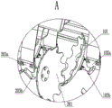
Fig. 4 is a partially enlarged view of a portion a in fig. 3.
Fig. 5 is a perspective view of the present invention, fig. 2.
Fig. 6 is a partially enlarged view of fig. 5 at B.
Fig. 7 is a partial enlarged view at C in fig. 5.
Fig. 8 is a perspective view of the present invention, fig. 3.
Fig. 9 is a partial enlarged view of fig. 8 at D.
Fig. 10 is a perspective view of the present invention, fig. 4.
Fig. 11 is a partial enlarged view at E in fig. 10.
Fig. 12 is a perspective view showing the movable frame of the present invention folded upward.
Wherein, 1 the second stubble cleaning component, 101 the second stubble cleaning harrow, 102 the second connecting seat, 103 the second connecting plate, 2 the first stubble cleaning component, 201 the first stubble cleaning harrow, 202 the first connecting plate, 203 the first connecting seat, 3 the machine frame, 4 the driving rod, 5 the linear driver, 6 the movable frame, 7 the press component, 701 the supporting wheel, 702 the press shaft, 703 the press rod, 704 the press plate, 705 the supporting plate, 706 the press wheel, 707 the buffer part, 708 the connecting hole, 709 the press spring, 710 the connecting rod, 711 the regulating wheel, 712 the connecting wheel, 8 the traction frame, 9 the screw rod two, 10 the thread bush, 11 the screw rod one, 12 the deep scarification component, 1201 the deep scarification plate, 1202 the deep scarification seat, 1203 the front buffer shaft, 1204 the front connecting shaft, 1205 the regulating plate, 1206 the buffer spring, 1207 the rear connecting shaft 1208, the rear buffer shaft, 1209 the fixed plate, 1210 the deep scarification shovel, 13 the lifting driver, 14 the lifting rod, 15 the supporting limit wheel, 16 the stubble cleaning frame, 17, 19 front adjusting rods, 20 front adjusting sleeves, 21 rear adjusting rods, 22 front hinged seats, 23 connecting lugs, 24 rear adjusting sleeves, 25 lower supporting rods and 26 upper supporting rods.
Detailed Description
The invention is further described below with reference to the accompanying drawings.
As shown in fig. 1 to 12, the compacting stubble cleaning device convenient for transportation comprises a frame 3, wherein the left and right ends of the frame 3 are respectively connected with a movable frame 6 capable of rotating upwards, one end of the frame 3 extending backwards out of the movable frame 6 is connected with a lifting frame capable of lifting, one end of the frame 3 facing backwards is hinged with a lifting driver 13, the lifting driver 13 is connected with a lifting rod 14 extending backwards, one end of the lifting rod 14 extending outwards is hinged with the lifting frame, and the upper end of the lifting frame is hinged with the frame 3; the left end and the right end of the lower part of the lifting frame are rotatably connected with supporting limiting wheels 15, a subsoiling assembly 12I is connected on the movable frame 6, the subsoiling assembly 12I comprises a plurality of subsoiling seats 1202 arranged on the movable frame 6, a subsoiling shovel 1210 is connected on each subsoiling seat 1202, at least one group of press assemblies 7 is connected on the movable frame 6 behind the subsoiling assembly 12I, each press assembly 7 comprises two support plates which are arranged at intervals in the left-right direction and connected on the movable frame 6, a press plate 704 is fixed between the two support plates 705 which extend backwards beyond one end of the press wheel 706, the rear end of the frame 3 is connected with a support assembly corresponding to the press assembly 7, each support assembly comprises at least two upper supporting rods 26, the upper ends of the upper supporting rods 26 are hinged on the frame 3, one ends of the upper supporting rods 26 which extend backwards and backwards are in threaded connection with a rear adjusting sleeve 24, the lower part of the rear adjusting sleeve 24 is in, the screw thread directions of the upper supporting rod 26 and the lower supporting rod 25 are opposite, one end of the lower supporting rod 25 extending downwards is hinged with a press plate 704, the height adjustment of the press wheel 706 is realized through the arrangement of the upper supporting rod 26, the rear adjusting sleeve 24 and the lower supporting rod 25, a press shaft 702 is rotatably connected between the two supporting plates 705, the left end and the right end of the press shaft 702 are respectively rotatably connected with two press wheels 706, a plurality of press rods 703 are arranged outside the two press wheels 706, a plurality of supporting wheels 701 are arranged inside the press rods 703 between the two press wheels 706 in the same group of press components 7, a gap is formed between each supporting wheel 701 and the press shaft 702, and the position change of the press wheels 706 is carried out along with the press wheels 706 while the press wheels are supported; a connecting wheel 712 is connected to the pressing shaft 702 corresponding to the pressing wheel 706, buffer portions 707 are arranged at the left end and the right end of the connecting wheel 712, a plurality of connecting holes 708 are arranged on the buffer portions 707, an adjusting wheel 711 is connected to the inner side of the pressing wheel 706, a plurality of connecting rods 710 corresponding to the connecting holes 708 one by one are arranged on the periphery of the left end and the right end of the adjusting wheel 711, a pressing spring 709 is connected to the connecting rod 710, and one end of the pressing spring 709, far away from the connecting rod 710, is inserted into the corresponding connecting hole 708 and is connected with the buffer portions 707.
In order to further realize the angle modulation of adjustable shelf 6, the upside at both ends is fixed with articulated seat 18 down around the adjustable shelf 6, both ends all are equipped with articulated seat 17 on two of interval setting in the front rear direction about frame 3, it is articulated with the articulated seat 18 down that corresponds to go up articulated seat 17, adjustable shelf 6 one end up articulates there is linear actuator 5, be connected with on the linear actuator 5 towards the actuating lever 4 that frame 3 place direction tilt up stretches out, the one end that actuating lever 4 upwards stretches out is articulated with frame 3.
In order to further improve the deep loosening effect, the lower part of a deep loosening seat 1202 is connected with a deep loosening plate 1201, the deep loosening seat 1202 above the deep loosening plate 1201 is connected with a front connecting shaft 1204, the front connecting shaft 1204 is connected with at least one front buffer shaft 1203 horizontally extending backwards, in the embodiment, two front buffer shafts 1203 are arranged, an adjusting plate 1205 is in threaded connection with the front buffer shaft 1203, a buffer spring 1206 is sleeved on the front buffer shaft 1203, a rear buffer shaft 1208 is sleeved on the front buffer shaft 1203, the left side and the right side of the deep loosening plate 1201 are connected with fixing plates 1209, one end, extending backwards, of the rear buffer shaft 1208 is connected with a rear connecting shaft 1207, the rear connecting shaft 1207 is connected with the fixing plate 1209, one forward end of the buffer spring 1206 abuts against the adjusting plate 1205, one rearward end of the buffer spring 1206 abuts against a limiting step of the rear buffer shaft 1208, and a deep loosening shovel 1210 is fixedly connected with one downward end; a plurality of subsoiling assemblies 12 II are further arranged on the movable frame 6 between the first subsoiling assembly 12 and the pressing assembly 7, the second subsoiling assemblies 12 and the first subsoiling assembly 12 are arranged in a staggered mode in the left-right direction, and the first subsoiling assembly 12 and the second subsoiling assembly 12 are identical in structure.
In order to reduce the resistance in deep scarification, the front of the movable frame 6 is connected with a stubble cleaning frame 16, the concrete connection structure is that two front hinging seats 22 are arranged at the front end of the movable frame 6, two connecting lugs 23 which are in one-to-one correspondence with the front hinging seats 22 are arranged at the upper side of the stubble cleaning frame 16, the front of the movable frame 6 is connected with at least two rear adjusting rods 21, one end of each rear adjusting rod 21 which extends downwards and forwards is connected with a front adjusting sleeve 20 in a threaded manner, at least two front adjusting rods 19 are hinged on the stubble cleaning frame 16, one end of each front adjusting rod 19 which extends backwards is connected with one end of each front adjusting sleeve 20 which is far away from the rear adjusting rod 21 in a threaded manner, the threaded directions of the front adjusting rod 19 and the rear adjusting rod 21 are opposite, the front of the stubble cleaning frame 16 is connected with a stubble cleaning assembly I2, the stubble cleaning assembly I2 comprises a plurality of connecting plates 202 which are arranged, the other end of the first connecting plate 202 upwards bypasses the upper part of the stubble ploughing frame 16 and then downwards inclines and extends, the other end of the first connecting plate 202 is connected with a first connecting seat 203, the first connecting seat 203 comprises a first connecting part 203a, one end of the first connecting part 203a is fixedly connected with the first connecting plate 202, one end of the other end of the first connecting part 203a in the left-right direction is connected with a first rotating supporting part 203b, the first rotating supporting part 203b forwards and upwards inclines, the first stubble ploughing rake 201 is rotatably connected to the first rotating supporting part 203b, and the central axis of the first stubble ploughing rake 201 is coincided with the central axis of the.
In order to further reduce the resistance in the deep scarification process, a stubble cleaning assembly II 1 is connected to the stubble cleaning frame 16 behind the stubble cleaning assembly I2, the stubble cleaning assembly II 1 comprises a plurality of connecting plates II 103 which are arranged on the stubble cleaning frame 16 in the same row, one ends of the connecting plates II 103 are fixed to the lower side of the stubble cleaning frame 16, the other ends of the connecting plates II 103 upwards bypass the upper part of the stubble cleaning frame 16 and downwards incline to extend out, the other ends of the connecting plates II 103 are connected with a connecting seat II 102, and a stubble cleaning harrow II 101 is rotatably connected to the connecting seat II 102; the second connecting seat 102 comprises a second connecting part 102a, the second connecting part 102a is fixed at the other end of the second connecting plate 103, one end of the other end of the second connecting part 102a in the left-right direction is connected with a second rotating supporting part 102b, the second rotating supporting part 102b inclines forwards and upwards, the central axis of the second stubble cleaning harrow 101 is overlapped with the central axis of the second rotating supporting part 102b, in the left-right direction, the first rotating supporting part 203b is arranged opposite to the corresponding second rotating supporting part 102b, and the second stubble cleaning harrow 101 is rotatably connected to the second rotating supporting part 102 b.
According to the invention, the front end of a rack 3 is hinged with a traction frame 8, the front end of the traction frame 8 is provided with a traction ring, the traction frame 8 is connected to the rear of a walking device through the traction ring (the prior art is adopted), the traction frame 8 and the rack 3 are connected together in a lifting manner, a manual adjusting mode is provided in the application, specifically, a screw rod I11 is hinged on the traction frame 8, one end, extending backwards, of the screw rod I11 is connected with a threaded sleeve 10 in a threaded manner, one end, extending backwards, of the threaded sleeve 10 is connected with a screw rod II 9 in a threaded manner, one end, extending backwards, of the screw rod II 9 is hinged with the rack 3, and the thread turning directions of the screw rod I11 and the; the traction frame 8 can also be connected with the frame 3 through a hydraulic cylinder; when the stubble cleaning harrow I201 does not work, the lifting driver 13 acts, the lifting rod 14 extends downwards, the lifting frame descends, and the lifting frame drives the supporting limiting wheel 15 to move, so that the stubble cleaning harrow I201 leaves the ground; the first connecting plate 202 and the second connecting plate 103 have the same structure, the first stubble ploughing rake 201 and the second stubble ploughing rake 101 have the same structure, in the embodiment, the first stubble ploughing rake 201 is arranged towards the right, the second stubble ploughing rake 101 is arranged towards the left, and the forward and upward inclined angles of the first stubble ploughing rake 201 and the second stubble ploughing rake 101 are the same; in the initial state, the movable frame 6 is upwards in a folded state, so that the transportation is convenient; the lifting drive 13 is preferably a hydraulic cylinder; in the field preparation work, if the stubble ploughing frames 16 are not in the horizontal state, the corresponding front adjusting sleeves 20 are rotated, and when the two stubble ploughs 16 are kept horizontal and are basically at the same height, the adjustment is finished; the height of the press wheel 706 is adjusted similarly to the method for adjusting the levelness of the stubble ploughing frame 16, and the details are not repeated herein; the lifting driver 13 works to enable the lowest position of the supporting limiting wheel 15 to be flush with the lowest position of the press wheel 706, the linear driver 5 acts to enable the driving rod 4 to extend outwards, the driving rod 4 pushes the upper end of the movable frame 6 to rotate downwards, and when the movable frame 6 is in a horizontal state, the linear driver 5 stops acting; when the stubble cleaning machine works, the walking device advances in the field, the movable frame 6 is unfolded downwards, the upper side of the movable frame 6 is in a horizontal state, the press wheel 706 is supported through height adjustment of the supporting limiting wheel 15, the machine frame 3 advances along with the walking device, the stubble cleaning rake 201 rolls forwards along with the walking device, a plurality of stubble cleaning teeth are arranged on the peripheries of the stubble cleaning rake 201 and the stubble cleaning rake 101, stubble cleaning and soil loosening of the stubble cleaning rake 201 and the stubble cleaning rake 101 are carried out, impact during operation of the stubble cleaning rake 201 is reduced by arranging the elastic pressing type connecting plate 202, the change of the terrain is induced, the stubble cleaning effect is improved, the stubble cleaning rake 101 carries out stubble cleaning and soil loosening again on the basis of the stubble cleaning rake 201, the installation positions of the stubble cleaning rake 201 and the stubble cleaning rake 101 in the left and right directions are opposite, the stubble cleaning and soil loosening effects are improved, the arrangement of the connecting plate 103 is used for reducing the impact of the stubble cleaning rake 101 and inducing the change of the terrain, the stubble cleaning and soil loosening effects are further improved; the subsoiling shovel 1210 performs subsoiling on the basis of stubble cleaning to reduce subsoiling resistance, during subsoiling, after the subsoiling shovel 1210 enters the soil, the traction force and the soil resistance are balanced at a specific depth, when the soil resistance is obviously increased due to meeting of a slope or different soil textures, the soil pushes the subsoiling shovel 1210 to lift anticlockwise and upwards, the buffer spring contracts, and the tension is increased; when the soil resistance is reduced, the tension of the buffer spring pushes the subsoiler 1210 to move clockwise and downwards, self-excited vibration is formed on the soil above the shovel tip surface of the subsoiler 1210, the subsoiling effect is improved, and when an obstacle is met, the impact on the subsoiler 1210 can also be reduced; finally, compacting the deeply-loosened field, compacting by the compacting wheel 706, wherein in the advancing process, the compacting wheel 706 keeps balance under the action of the compacting rod 703, when the compacting wheel 706 encounters an obstacle with higher height, the obstacle jacks up the corresponding compacting wheel 706, the compacting wheel 706 overcomes the pressure of the compacting spring 709, the contact part of the compacting wheel 706 and the obstacle moves towards the direction of the compacting shaft 702, the compacting wheel 706 starts to cross the obstacle, the compressed compacting spring 709 resets, the compacting wheel 706 part which displaces in the radial direction quickly resets under the action of the compacting spring 709, and when the obstacle is completely crossed, all the compacting springs 709 reset and the compacting operation is continuously completed; the subsoiling shovel 1210 carries out subsoiling plowing, and the press wheel 706 presses the soil after subsoiling, so that the field is leveled; the invention is convenient to transport, and can complete stubble cleaning, deep scarification and compacting operation at the same time; can be applied to the deep scarification operation of farmlands.
The present invention is not limited to the above-mentioned embodiments, and based on the technical solutions disclosed in the present invention, those skilled in the art can make some substitutions and modifications to some technical features without creative efforts according to the disclosed technical contents, and these substitutions and modifications are all within the protection scope of the present invention.
Claims (9)
Priority Applications (1)
| Application Number | Priority Date | Filing Date | Title |
|---|---|---|---|
| CN202011189215.4A CN112243614B (en) | 2020-10-30 | 2020-10-30 | Pressing stubble cleaning device convenient to transport |
Applications Claiming Priority (1)
| Application Number | Priority Date | Filing Date | Title |
|---|---|---|---|
| CN202011189215.4A CN112243614B (en) | 2020-10-30 | 2020-10-30 | Pressing stubble cleaning device convenient to transport |
Publications (2)
| Publication Number | Publication Date |
|---|---|
| CN112243614A true CN112243614A (en) | 2021-01-22 |
| CN112243614B CN112243614B (en) | 2023-07-07 |
Family
ID=74267878
Family Applications (1)
| Application Number | Title | Priority Date | Filing Date |
|---|---|---|---|
| CN202011189215.4A Active CN112243614B (en) | 2020-10-30 | 2020-10-30 | Pressing stubble cleaning device convenient to transport |
Country Status (1)
| Country | Link |
|---|---|
| CN (1) | CN112243614B (en) |
Citations (17)
| Publication number | Priority date | Publication date | Assignee | Title |
|---|---|---|---|---|
| US3983943A (en) * | 1973-10-26 | 1976-10-05 | Lely Cornelis V D | Soil cultivating implement combinations |
| CA1023600A (en) * | 1975-02-06 | 1978-01-03 | Cornelis J. Steketee | Ground working implement |
| GB2000005A (en) * | 1977-06-20 | 1979-01-04 | Pavan J | Seed-Sowing Device |
| EP1529430A1 (en) * | 2003-11-06 | 2005-05-11 | Väderstad-Verken AB | Device at a soil tillage implement |
| US20070169950A1 (en) * | 2006-01-26 | 2007-07-26 | J. & M. Manufacturing Co., Inc. | Folding soil conditioning farm implement |
| CN201911008U (en) * | 2010-12-30 | 2011-08-03 | 王泽文 | Compound minimum tillage land preparation machine |
| CN202857247U (en) * | 2012-10-13 | 2013-04-10 | 黑龙江省农业机械运用研究所 | Wide-width folding hydraulic drive stubble cleaning and ridging combination land preparation machine |
| CN103918362A (en) * | 2014-04-29 | 2014-07-16 | 吉林大学 | Profiling bionic press roller |
| CN103959939A (en) * | 2014-04-29 | 2014-08-06 | 吉林大学 | Press wheel with press force monitoring function |
| CN204291766U (en) * | 2014-12-02 | 2015-04-29 | 阿拉尔新思路农业机械制造有限责任公司 | Large-scale automatic flap type combined soil preparation machine |
| CN204948633U (en) * | 2015-09-18 | 2016-01-13 | 新疆阿拉尔金准机械制造有限公司 | Biasing pressurization harrow unit and soil preparation machine |
| CN105612841A (en) * | 2016-03-09 | 2016-06-01 | 华中农业大学 | Profiling ditching pressing device |
| WO2017062556A1 (en) * | 2014-10-09 | 2017-04-13 | Jordan Ben | Soil tillage apparatus and method |
| CN106879265A (en) * | 2017-01-24 | 2017-06-23 | 中国农业科学院农业资源与农业区划研究所 | A kind of maize straw in the ranks chopper |
| CN208079696U (en) * | 2018-04-02 | 2018-11-13 | 甘肃农业大学 | A kind of mountainous region self-excited vibration subsoiling land preparation suppression combine |
| CN208624055U (en) * | 2018-04-02 | 2019-03-22 | 甘肃农业大学 | A strong anti-blocking type no-till fertilization seeder |
| CN210247424U (en) * | 2019-04-28 | 2020-04-07 | 诸城市永成机械厂 | Deep scarification, stubble cleaning, rotary tillage and ridging combined soil preparation machine capable of adjusting ridges |
-
2020
- 2020-10-30 CN CN202011189215.4A patent/CN112243614B/en active Active
Patent Citations (17)
| Publication number | Priority date | Publication date | Assignee | Title |
|---|---|---|---|---|
| US3983943A (en) * | 1973-10-26 | 1976-10-05 | Lely Cornelis V D | Soil cultivating implement combinations |
| CA1023600A (en) * | 1975-02-06 | 1978-01-03 | Cornelis J. Steketee | Ground working implement |
| GB2000005A (en) * | 1977-06-20 | 1979-01-04 | Pavan J | Seed-Sowing Device |
| EP1529430A1 (en) * | 2003-11-06 | 2005-05-11 | Väderstad-Verken AB | Device at a soil tillage implement |
| US20070169950A1 (en) * | 2006-01-26 | 2007-07-26 | J. & M. Manufacturing Co., Inc. | Folding soil conditioning farm implement |
| CN201911008U (en) * | 2010-12-30 | 2011-08-03 | 王泽文 | Compound minimum tillage land preparation machine |
| CN202857247U (en) * | 2012-10-13 | 2013-04-10 | 黑龙江省农业机械运用研究所 | Wide-width folding hydraulic drive stubble cleaning and ridging combination land preparation machine |
| CN103959939A (en) * | 2014-04-29 | 2014-08-06 | 吉林大学 | Press wheel with press force monitoring function |
| CN103918362A (en) * | 2014-04-29 | 2014-07-16 | 吉林大学 | Profiling bionic press roller |
| WO2017062556A1 (en) * | 2014-10-09 | 2017-04-13 | Jordan Ben | Soil tillage apparatus and method |
| CN204291766U (en) * | 2014-12-02 | 2015-04-29 | 阿拉尔新思路农业机械制造有限责任公司 | Large-scale automatic flap type combined soil preparation machine |
| CN204948633U (en) * | 2015-09-18 | 2016-01-13 | 新疆阿拉尔金准机械制造有限公司 | Biasing pressurization harrow unit and soil preparation machine |
| CN105612841A (en) * | 2016-03-09 | 2016-06-01 | 华中农业大学 | Profiling ditching pressing device |
| CN106879265A (en) * | 2017-01-24 | 2017-06-23 | 中国农业科学院农业资源与农业区划研究所 | A kind of maize straw in the ranks chopper |
| CN208079696U (en) * | 2018-04-02 | 2018-11-13 | 甘肃农业大学 | A kind of mountainous region self-excited vibration subsoiling land preparation suppression combine |
| CN208624055U (en) * | 2018-04-02 | 2019-03-22 | 甘肃农业大学 | A strong anti-blocking type no-till fertilization seeder |
| CN210247424U (en) * | 2019-04-28 | 2020-04-07 | 诸城市永成机械厂 | Deep scarification, stubble cleaning, rotary tillage and ridging combined soil preparation machine capable of adjusting ridges |
Non-Patent Citations (2)
| Title |
|---|
| 杨华;王欣;孙士明;韩宏宇;程亨曼;: "1GZM-350型灭茬深松整地联合作业机的研究", 农机化研究, no. 11 * |
| 许剑平;徐涛;毛俐;: "1DF-7760型复式少耕整地机的设计", 农机化研究, no. 04 * |
Also Published As
| Publication number | Publication date |
|---|---|
| CN112243614B (en) | 2023-07-07 |
Similar Documents
| Publication | Publication Date | Title |
|---|---|---|
| CN202050658U (en) | Framed rotary tillage and seeding compound machine | |
| US5161622A (en) | Field cultivator leveling device | |
| CN103109600B (en) | Paddy field stubble burying cultivator | |
| CN207124866U (en) | A kind of novel combination type subsoiling land preparation working rig | |
| CN212278739U (en) | Combined type mechanical weeding machine | |
| US4444271A (en) | Tillage apparatus with independent depth adjustment | |
| CN107278478A (en) | Picker for tuber crops digs deep regulation device | |
| CN112868338A (en) | High-clearance riding type double-row green Chinese onion hiller and hilling method | |
| CN112243615A (en) | Stubble-cleaning subsoiling and pressing integrated operation machine | |
| US6257342B1 (en) | Soil grading apparatus | |
| CN213991596U (en) | Soil loosening device for agriculture | |
| CN112243614A (en) | Compacting stubble-cleaning device of convenient transportation | |
| CN213485570U (en) | Deep scarification and pressing device | |
| CN213755595U (en) | A device for stubble removal and deep loosening | |
| KR101056401B1 (en) | Tractor Plows | |
| CN112088864B (en) | a weeder | |
| CN215500351U (en) | Seedbed flat land compactor | |
| CN112262628B (en) | A parallel operation device for rice and wheat planting | |
| CN108307700A (en) | A kind of more landform finishing rakes | |
| CN216087468U (en) | Shallow loose type laser land leveler for agriculture | |
| CN112005639B (en) | A composite mechanical weeder | |
| CN113597833A (en) | Combined soil preparation machine | |
| CN203912485U (en) | A kind of farm flattening machinery | |
| CN202340383U (en) | Paddy field stubble burying cultivator | |
| CN216253794U (en) | Agricultural machine plowing mechanism convenient to replace |
Legal Events
| Date | Code | Title | Description |
|---|---|---|---|
| PB01 | Publication | ||
| PB01 | Publication | ||
| SE01 | Entry into force of request for substantive examination | ||
| SE01 | Entry into force of request for substantive examination | ||
| GR01 | Patent grant | ||
| GR01 | Patent grant |