CN112127370A - Reverse plugging method for non-construction fender post part of main body fender structure of station - Google Patents
Reverse plugging method for non-construction fender post part of main body fender structure of station Download PDFInfo
- Publication number
- CN112127370A CN112127370A CN202010955739.3A CN202010955739A CN112127370A CN 112127370 A CN112127370 A CN 112127370A CN 202010955739 A CN202010955739 A CN 202010955739A CN 112127370 A CN112127370 A CN 112127370A
- Authority
- CN
- China
- Prior art keywords
- blocking wall
- foundation pit
- main ribs
- construction
- vertical main
- Prior art date
- Legal status (The legal status is an assumption and is not a legal conclusion. Google has not performed a legal analysis and makes no representation as to the accuracy of the status listed.)
- Pending
Links
Images


Classifications
-
- E—FIXED CONSTRUCTIONS
- E02—HYDRAULIC ENGINEERING; FOUNDATIONS; SOIL SHIFTING
- E02D—FOUNDATIONS; EXCAVATIONS; EMBANKMENTS; UNDERGROUND OR UNDERWATER STRUCTURES
- E02D17/00—Excavations; Bordering of excavations; Making embankments
- E02D17/02—Foundation pits
- E02D17/04—Bordering surfacing or stiffening the sides of foundation pits
-
- E—FIXED CONSTRUCTIONS
- E02—HYDRAULIC ENGINEERING; FOUNDATIONS; SOIL SHIFTING
- E02D—FOUNDATIONS; EXCAVATIONS; EMBANKMENTS; UNDERGROUND OR UNDERWATER STRUCTURES
- E02D29/00—Independent underground or underwater structures; Retaining walls
- E02D29/045—Underground structures, e.g. tunnels or galleries, built in the open air or by methods involving disturbance of the ground surface all along the location line; Methods of making them
Landscapes
- Engineering & Computer Science (AREA)
- Mining & Mineral Resources (AREA)
- Life Sciences & Earth Sciences (AREA)
- General Life Sciences & Earth Sciences (AREA)
- Paleontology (AREA)
- Civil Engineering (AREA)
- General Engineering & Computer Science (AREA)
- Structural Engineering (AREA)
- Environmental & Geological Engineering (AREA)
- Bulkheads Adapted To Foundation Construction (AREA)
Abstract
The invention provides a reverse plugging method for a part of a station main body enclosure structure where no enclosure pile is constructed. The plugging method is used for plugging an area where a fender pile cannot be constructed when a cast-in-situ bored pile is adopted for a station main body fender structure, fender pile bodies are arranged on two sides of a plugging part of the area, and the specific construction steps are as follows: the method comprises the steps of pre-burying a vertical main rib of a top area of a blocking wall in a crown beam of a part to be blocked when constructing a crown beam of the enclosure structure, constructing a reverse blocking wall in the part to be blocked from top to bottom in the excavation process of a foundation pit, welding two ends of a transverse main rib of the blocking wall with main ribs of adjacent enclosure piles on two sides of the part to be blocked respectively, and arranging the bottom surface of the blocking wall below a foundation pit base by 0.5-1 m. The method solves the problems of settlement of the pavement of the surrounding foundation pit, deformation of the foundation pit, collapse, water gushing, sand gushing and the like caused by the fact that the enclosure structure cannot be closed due to the fact that part of pile bodies of the existing enclosure pile structure cannot be constructed normally, and is suitable for the stratum with good stability such as a clay layer.
Description
Technical Field
The invention relates to the field of foundation pit construction, in particular to a reverse plugging method for a part of a station main body enclosure structure where a fender post is not constructed.
Background
The foundation pit enclosure structure is an important component of underground engineering and is mainly divided into an underground continuous wall, a cast-in-situ bored pile, a construction pile and the like according to different construction processes, and the foundation pit enclosure structure is usually formed by single-width (root) splicing during construction. The station main body enclosure structure is mainly characterized in that cast-in-situ bored piles and an inner support system are adopted, the cast-in-situ bored piles are adopted as the main body enclosure piles, concrete baffles are arranged among the piles to keep soil bodies among the piles stable, crown beams are arranged on pile tops, a plurality of supports are vertically adopted for a station main body foundation pit, and partition sections among the supports are connected through connecting beams.
In the process of foundation pit construction, communication lines or other pipelines often cross the foundation pit to influence the pile body construction of the fender pile, and particularly, when the pile position is located at a road intersection, the traffic flow is high, the pipelines cannot be moved and changed, so that the pile body of the pile position cannot be constructed, and a gap can be formed at the position. The foundation pit is not constructed with the fender post, so that the situation of collapse, leakage, water gushing, sand gushing and the like can occur at the part, and a series of chain reactions are generated. Although these ancillary works are small in size and not technically complex, once an accident occurs, the handling and recovery of the accident will be very complex and difficult, and will have a serious impact on the overall construction period and the public confidence of the enterprise. And when the stratum of the foundation pit is mainly filled with miscellaneous filling soil, clay silt and silty clay, the negative three-layer of the station is below the underground water level, and the fender post is not constructed, which may cause major potential safety hazards such as settlement of peripheral road surfaces, deformation, collapse, water burst, sand burst and the like of the foundation pit, so that how to scientifically and efficiently process the fender post problem of the individual fender post of the main body fender structure, the safe and stable excavation, supporting and structural construction of the foundation pit is realized, and the key problem of the station construction is solved.
Disclosure of Invention
The invention provides a reverse plugging method for a part of a station main body enclosure structure where a fender post is not constructed according to the defects of the prior art, and the method can solve the problems that the enclosure structure cannot be closed due to the fact that part of a pile body of the existing fender post structure cannot be constructed normally, and accordingly the surrounding foundation pit road surface is settled, the foundation pit is deformed, collapsed, gushes water, gushes sand and the like.
In order to solve the technical problem, the invention provides a reverse plugging method for a part of a station main body enclosure structure where a fender post is not constructed, which is characterized by comprising the following steps of: when the plugging method aims at a station main body enclosure structure and adopts a cast-in-situ bored pile and an internal support system, the part of the enclosure structure, which is not constructed with the enclosure pile, is plugged, and enclosure pile bodies are respectively arranged on two sides of the plugging part, and the concrete construction steps are as follows:
(1) the method comprises the steps that when a crown beam of the enclosure structure is constructed, vertical main ribs of the top area of a blocking wall are pre-embedded in the crown beam at a position to be blocked, the vertical main ribs are arranged at intervals of an inner row and an outer row, the length of the vertical main ribs anchored into the crown beam at the top area of the blocking wall is not less than 35 times of the diameter of the vertical main ribs, and the reserved staggered distance of the vertical main ribs is not less than 35 times of the diameter of the vertical main ribs;
(2) after the construction of the top beam in the step (1) is completed, excavating a foundation pit, excavating for the first time to a depth of 1-2 meters, and in the process of excavating the foundation pit, excavating a soil body at a part to be blocked by using an excavator and manually leveling the soil body; meanwhile, vertically chiseling concrete protective layers at positions 7-9 cm inside arc tops of adjacent fender pile bodies on two sides of the part to be plugged, and exposing vertical main ribs of the fender piles;
(3) welding main ribs of a blocking wall in an initial excavation region, firstly welding the lower ends of two rows of pre-buried vertical main ribs in the step (1) to the position below the excavation bottom surface of the foundation pit, then welding a plurality of transverse main ribs on the outer side of each row of vertical main ribs to form a reinforcing mesh structure, wherein each row of vertical main ribs and the transverse main ribs are connected by spot welding, and the connection point position of the vertical main ribs and the transverse main ribs is not less than 50%; two ends of each transverse main rib are welded with the vertical main ribs of the adjacent fender piles, and the welding length is not less than 5 times of the diameter of each transverse main rib; the two rows of reinforcing mesh sheets are connected by using the pull hook ribs;
(4) installing a template on the outer side of the reinforcing mesh structure close to the side of the foundation pit, wherein the template is positioned between the arc tops of adjacent fender pile bodies, erecting a plurality of square timbers on the back surface of the template, transversely arranging a plurality of steel supports on the back surfaces of the square timbers, and welding two ends of each steel support with the vertical main ribs of the adjacent fender piles respectively;
(5) after the template is installed, concrete is poured in a blocking wall area surrounded by the template, the fender post and the outside soil body, manual vibration is adopted to compact the blocking wall area after the pouring is finished, and the template is removed and maintained according to the standard when the concrete reaches the initial strength, so that the construction of a first section of blocking wall is finished;
(6) after the construction of the first section of blocking wall is finished, continuing excavating a foundation pit, repeating the steps (2) to (5) to segment the construction blocking wall to the bottom surface of the foundation pit, wherein the excavation depth of the foundation pit is 1-2 m each time, the vertical main rib of each section of blocking wall is welded with the vertical main rib of the upper section of blocking wall, a material port is reserved at the top of a template in the process of erecting the template of each section of blocking wall, after the template is erected, pouring concrete through the material port to finish the construction of the section of blocking wall, and after the concrete is poured, sealing the material port or flattening the position of the material port after the construction of the section of concrete blocking wall is finished;
(7) and (3) after the foundation pit is dug to the bottom surface, continuously excavating the soil around the blocking wall for 0.5-1 m, repeating the steps (2) - (5) to continuously construct the blocking wall with the thickness of 0.5-1 m below the foundation pit, and after the blocking wall below the foundation pit reaches the designed strength, filling the soil around the blocking wall to be flush with the pit bottom of the foundation pit, thereby completing the construction of the whole blocking wall.
The further technical scheme of the invention is as follows: the plugging method aims at a clay stratum or a foundation pit support structure in a rock stratum area.
The invention has the following excellent technical scheme: in the step (3), both the vertical main ribs and the horizontal main ribs of the plugging wall are made of phi 12 deformed steel bars; the hook pulling ribs are arranged at intervals of 20cm in the horizontal direction and 20cm in the vertical direction.
The invention has the following excellent technical scheme: and (5) vertically installing a PVC (polyvinyl chloride) drain pipe with the diameter of 4-6 cm before concrete pouring, wherein the water outlet of the drain pipe faces the inside of the foundation pit.
The invention has the following excellent technical scheme: and (5) adopting commercial concrete with the model number of C35P8 as the concrete in the step, and removing the template after the concrete pouring is finished for 11-13 h.
The invention has the beneficial effects that:
(1) the invention achieves the effect of enclosing the enclosure structure by reliably connecting the steel bars of the enclosing wall with the top crown beam and the enclosure piles at two sides, has good water-stopping and reinforcing effects, solves the problem that the enclosure structure cannot be enclosed because part of the pile body of the existing enclosure pile structure cannot be normally constructed, avoids the problems of pavement settlement, foundation pit deformation, collapse, water gushing, sand gushing and the like caused by poor enclosing effect of the foundation pit, eliminates the great potential safety hazard of foundation pit construction, has simple construction technology process and easy control of process construction quality, and is suitable for being used in construction methods of similar strata.
(2) The method has the advantages that the steel bars are embedded in the blocking wall in the construction stage of the crown beam, so that the effective connection of the steel bars is ensured, the binding of the steel bars and the connection of adjacent fender piles are good, the quality is controllable, and the enclosure structure is ensured to be sealed into a whole;
(3) the template provided by the invention has good stability, meets the concrete pouring conditions, is compacted through manual vibration after concrete pouring, ensures the strength of the blocking wall, ensures the drainage of the blocking wall by vertically installing the left and right PVC pipe drainage holes before concrete pouring, meets the requirements on the strength performance of the blocking wall, and ensures the quality safety of the foundation pit after construction.
Drawings
FIG. 1 is a schematic structural view of the present invention;
FIG. 2 is a schematic view of a rebar junction according to the present invention;
FIG. 3 is a cross-sectional view of AA in FIG. 1, in accordance with the present invention;
FIG. 4 is a transverse cross-sectional view of the form assembly of the present invention;
FIG. 5 is a vertical plan view of the formwork erection of the present invention;
FIG. 6 is a schematic view of the lower layer reinforced concrete blocking wall pouring of the present invention;
FIG. 7 is a water and sand gushing amount graph of each stage of measures taken in the embodiment.
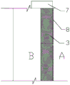
In the figure: 1-first fender pile, 2-second fender pile, 3-reinforced concrete blocking wall, 4-horizontal main rib, 5-vertical main rib of fender pile, 6-vertical main rib, 7-crown beam, 8-template, 9-soil body, 10-template support square timber, 11-feed opening, 12-template steel bracket, 13-hook rib, A-foundation pit side, B-soil body surface.
Detailed Description
The invention is further illustrated by the following figures and examples. Fig. 1 to 7 are drawings of embodiments, which are drawn in a simplified manner and are only used for the purpose of clearly and concisely illustrating the embodiments of the present invention. The following claims presented in the drawings are specific to embodiments of the invention and are not intended to limit the scope of the claimed invention. All other embodiments, which can be derived by a person skilled in the art from the embodiments given herein without making any creative effort, shall fall within the protection scope of the present invention.
In the description of the present invention, it is to be understood that the terms "upper", "lower", "inside", "outside", "left", "right", and the like, indicate orientations or positional relationships based on the orientations or positional relationships shown in the drawings, or the orientations or positional relationships that the products of the present invention are conventionally placed in use, or the orientations or positional relationships that are conventionally understood by those skilled in the art, and are used for convenience of describing the present invention and simplifying the description, but do not indicate or imply that the devices or elements referred to must have a specific orientation, be constructed in a specific orientation, and be operated, and thus, should not be construed as limiting the present invention. Furthermore, the terms "first," "second," and the like are used merely to distinguish one description from another, and are not to be construed as indicating or implying relative importance.
The invention is further explained by combining the embodiment, wherein the embodiment is that aiming at a subway station A of No. 6 line of a certain city, the station A is a three-layer station, the scheme of the main body enclosure structure of the station adopts a bored pile and an inner support system, and the main body enclosure pile adopts a bored pile and an inner support system The cast-in-situ bored piles are provided with C20 concrete baffles between the pilesKeeping the soil body between the piles stable. The pile top is provided with 1200 multiplied by 900mm top beams, the station main foundation pit is vertically provided with four supports, the third concrete support is provided with a 1000 multiplied by 1200mm waist beam, and the support partitions are connected by connecting beams. Main body enclosure structure adopts
 The cast-in-situ bored piles are A, A1-shaped piles in the west-end well, B, C-shaped piles in the standard section and 249 piles in total, C35 underwater concrete is adopted,
see table 1 for details. TABLE 1 statistical table for types of main body fender posts

The concrete supporting bottom is provided with The cast-in-situ bored pile (temporary upright pile) has a solid pile length of 17.5m, a rigid upright column size of 500 x 500mm, and an embedded pile length of 3m, and has 25 piles.
The northeast corner of the station influences the pile position because the communication line crosses the foundation pit, and the pile position is positioned at the road intersection, so that the traffic flow is high, the pipeline cannot be moved and changed, and one pile is not constructed; the southeast corner leads to three piles to be under construction because of communication line three calandrias influences such as broadcasting and TV communication, telecommunications, removal, UNICOM, great wall broadband, and can't move and change, peels off a tub cycloid through site operation personnel, and wherein two are under construction and accomplish, and remaining calandria influences a fender post and is not under construction.
The stratum of the station foundation pit mainly comprises miscellaneous filling soil, clay silt and silty clay, the negative three layer of the station is below the underground water level, and the fender post is not constructed, so that major potential safety hazards such as settlement of peripheral road surfaces, deformation of the foundation pit, collapse, water burst, sand burst and the like can be caused. To this end, the skilled person of the project proposes three solutions:
the first scheme is as follows: technical scheme for spraying concrete on wall
The steel bar net piece is hung on the soil surface and is adjacent to the embedded steel bars of the adjacent fender post, the commercial concrete spraying technology is adopted, the thickness of sprayed concrete is increased at the part where the fender post is not constructed, the strength grade of the concrete is improved, and the purpose of preventing water and collapse is achieved.
Scheme II: ground grouting reinforcement and jet coagulation and technical scheme
And (3) adopting a ground grouting technology, drilling and grouting above the part of the fender post which is not constructed, and hanging a net to spray concrete on the excavated soil body surface to fulfill the aim of reinforcing the soil body.
The third scheme is as follows: technical scheme of reverse construction plugging wall in application
And (3) reversely manufacturing a reinforced concrete wall with the thickness of 400mm from top to bottom at the position of the retaining pile which is not constructed for plugging, and reliably connecting the reinforcing steel bars of the plugging wall with the top crown beam and the retaining piles at the two sides to achieve the effect of sealing the retaining structure. The three schemes are compared and analyzed from multiple angles and multiple directions, and the analysis results are detailed in table 2.
Table 2 comparison table of technical effects of three schemes


Through comparative analysis of the three schemes, the responsible person of the project considers that the plugging method has more advantages in the aspects of technical feasibility, improvement of foundation pit excavation safety coefficient and construction difficulty degree, so that the plugging method of the reverse construction plugging wall is selected to be adopted to seal the part of the fender post which is not constructed. The following is a detailed description of the blocking process of one of the parts without the fender post, where two sides of the area to be blocked are respectively provided with the first fender post 1 and the second fender post 2, as shown in fig. 1, the reverse blocking wall is placed between the first fender post 1 and the second fender post 2, and the specific construction process is as follows:
(1) the method comprises the steps that when a building envelope crown beam is constructed, vertical main ribs 6 of the top area of a blocking wall are pre-embedded in the crown beam at a position to be blocked, the vertical main ribs 6 are C22 deformed steel bars, the vertical main ribs 6 are arranged at intervals of 200mm in an inner row and an outer row, the length of the vertical main ribs anchored into the crown beam at the top area of the blocking wall is not less than 35 times of the diameter of the vertical main ribs 6, and the preset staggered distance of the vertical main ribs 6 is not less than 35 times of the diameter of the vertical main ribs 6;
(2) after the construction of the top beam in the step (1) is completed, excavating a foundation pit, excavating for the first time to a depth of 1-2 meters, and in the process of excavating the foundation pit, excavating soil bodies of a first fender post 1 and a second fender post 2 by using an excavator and manually leveling; simultaneously, chiseling off the concrete protective layer at the position of 7-9 cm within the arc top of the first fender pile 1 and the second fender pile 2 every 20cm in the vertical direction, and exposing the vertical main rib 5 of the fender pile;
(3) welding main ribs of a blocking wall in an initial excavation region, as shown in fig. 2, firstly welding the lower ends of two rows of pre-embedded vertical main ribs 6 in the step (1) to the position below the excavation bottom surface of a foundation pit, then welding a plurality of transverse main ribs 4 on the outer side of each row of vertical main ribs 6 to form a reinforcing mesh structure, wherein the transverse main ribs 4 also adopt C22 deformed steel bars, each row of vertical main ribs 6 and the transverse main ribs 4 are connected by spot welding, and the connection point position of the transverse main ribs is not less than 50%; two ends of each transverse main rib 4 are welded with the vertical main ribs of the adjacent fender piles, and the welding length is not less than 5 times of the diameter of each transverse main rib 4; two rows of reinforcing mesh sheets are connected by using a pull hook rib 13, and are connected by using phi 12 deformed steel to manufacture pull hooks, wherein the pull hooks are arranged at intervals of 20cm in the horizontal direction and 20cm in the vertical direction;
(4) installing a template 8 at the outer side of the reinforcing mesh structure close to the foundation pit side, wherein as shown in fig. 4 and 5, the template 8 is positioned between the arc tops of the first fender pile 1 and the second fender pile 2, the distance between the template 8 and the soil body at the outer side is about 40cm, the thickness of the reinforcing steel bar protective layer of the blocking wall is about 5cm after the template 8 is installed, the surface of the template 8 is ensured to be flat when the template is erected, and the staggered joint is adhered by double faced adhesive tape; erecting a plurality of formwork supporting square timbers 10 on the back of the formwork 8, and transversely arranging a plurality of formwork steel brackets 12 on the back of the square timbers, wherein each formwork steel bracket 12 is made of I-shaped steel, and two ends of each formwork steel bracket are respectively welded with the vertical main ribs of the first fender post 1 and the second fender post 2;
(5) after the template 8 is installed, PVC pipe drain holes with the diameter of about 5cm are installed in the soil body of the concrete pouring area, the pipe openings of the PVC pipes are arranged on the inner side of the foundation pit, and accumulated water in the concrete pouring area is led into the foundation pit; then C35P8 commercial concrete is poured in a blocking wall area which is surrounded by the template 8, the fender post and the outer side soil body and has the width of 40cm, manual vibration is adopted to compact the blocking wall area after pouring, the initial strength is reached after the pouring of the concrete is finished for about 12 hours, and the template removal maintenance is carried out according to the standard to finish the construction of the first section of blocking wall;
(6) after the construction of the first section of blocking wall is finished, continuing excavating a foundation pit, repeating the step (2) to the step (5) for constructing the blocking wall to the bottom surface of the foundation pit in sections, wherein the excavation depth of the foundation pit is 1-2 m each time, the vertical main rib of each section of blocking wall is welded with the vertical main rib of the upper section of blocking wall, and in the process of erecting a template of each section of blocking wall, as shown in fig. 6, a material port is reserved at the top of the template;
(7) after the foundation pit is dug to the bottom surface, continuously excavating 0.5-1 m of soil around the blocking wall, repeating the steps (2) - (5) to continuously construct the blocking wall with the thickness of 0.5-1 m below the foundation pit, after the blocking wall below the foundation pit reaches the designed strength, filling the soil around the blocking wall to be flush with the pit bottom of the foundation pit, completing the construction of the whole blocking wall, wherein the thickness of the blocking wall is 40cm, and the completed blocking wall is shown in fig. 1 and 3.
After the construction of the reverse blocking wall is completed, in the construction links of foundation pit excavation and main body construction, the effect of the reverse blocking wall technology at the position of the retaining pile which is not constructed on the station main body enclosure structure is further confirmed by the inventor, and the target completion condition obtains the effect in the table 3:
table 3 project acceptance sheet


From the project acceptance sheet, it can be concluded: according to the construction method of the reverse construction blocking wall, the target of 0 collapse and water and sand gushing rate is achieved, the effect test curve chart is shown in fig. 7, the problems that the enclosure structure cannot be closed due to the fact that part of the pile body of the existing enclosure pile structure cannot be constructed normally, and accordingly the surrounding foundation pit road surface is settled, the foundation pit is deformed, the collapse, the water gushing and the sand gushing are caused can be solved well, and the construction method is suitable for the stratum with good stability such as a clay layer.
The skilled person in the project calculates the economic benefits obtained by the embodiment as follows:
the cost Max of the strategy table is equal to two reinforcement reservation strategies, two base surface excavation strategies, two reinforcement binding strategies, two template installation strategies and one concrete pouring strategy is equal to 2000 yuan, 10000 yuan, 90000 yuan, 30000 yuan, which is equal to 16.2 ten thousand yuan;
the implementation cost of the countermeasure is reinforcement reservation countermeasure I, base surface excavation countermeasure III, reinforcement binding countermeasure I, template installation countermeasure II and concrete pouring countermeasure I is 1500 yuan, 6000 yuan, 60000 yuan, 40000 yuan, 14.75 ten thousand yuan;
the risk cost is saved by 100 ten thousand yuan, and the management cost is 20 ten thousand yuan.
The economic benefits of the invention are mainly:
economic benefit (strategy table cost Max-strategy implementation cost) + risk cost + management cost (16.2-14.75) +100+20 121.45 ten thousand yuan
The benefit calculation shows that the method has good economic effect in specific application, greatly saves construction cost, effectively solves the problems of collapse, water inrush and water seepage at the position of the retaining pile which is not constructed, eliminates major potential safety hazards of foundation pit construction, has simple construction technology process and easy control of process construction quality, and is suitable for the construction method of similar stratum.
The above description is only one embodiment of the present invention, and the description is specific and detailed, but not construed as limiting the scope of the present invention. It should be noted that, for a person skilled in the art, several variations and modifications can be made without departing from the inventive concept, which falls within the scope of the present invention. Therefore, the protection scope of the present invention should be subject to the appended claims.
Claims (5)
1. A reverse plugging method for a part of a station main body enclosure structure where no guard post is constructed is characterized in that: when the plugging method aims at a station main body enclosure structure and adopts a cast-in-situ bored pile and an internal support system, the part of the enclosure structure, which is not constructed with the enclosure pile, is plugged, and enclosure pile bodies are respectively arranged on two sides of the plugging part, and the concrete construction steps are as follows:
(1) the method comprises the steps that when a crown beam of the enclosure structure is constructed, vertical main ribs of the top area of a blocking wall are pre-embedded in the crown beam at a position to be blocked, the vertical main ribs are arranged at intervals of an inner row and an outer row, the length of the vertical main ribs anchored into the crown beam at the top area of the blocking wall is not less than 35 times of the diameter of the vertical main ribs, and the reserved staggered distance of the vertical main ribs is not less than 35 times of the diameter of the vertical main ribs;
(2) after the construction of the top beam in the step (1) is completed, excavating a foundation pit, excavating for the first time to a depth of 1-2 meters, and in the process of excavating the foundation pit, excavating a soil body at a part to be blocked by using an excavator and manually leveling the soil body; meanwhile, vertically chiseling concrete protective layers at positions 7-9 cm inside arc tops of adjacent fender pile bodies on two sides of the part to be plugged, and exposing vertical main ribs of the fender piles;
(3) welding main ribs of a blocking wall in an initial excavation region, firstly welding the lower ends of two rows of pre-buried vertical main ribs in the step (1) to the position below the excavation bottom surface of the foundation pit, then welding a plurality of transverse main ribs on the outer side of each row of vertical main ribs to form a reinforcing mesh structure, wherein each row of vertical main ribs and the transverse main ribs are connected by spot welding, and the connection point position of the vertical main ribs and the transverse main ribs is not less than 50%; two ends of each transverse main rib are welded with the vertical main ribs of the adjacent fender piles, and the welding length is not less than 5 times of the diameter of each transverse main rib; the two rows of reinforcing mesh sheets are connected by using the pull hook ribs;
(4) installing a template on the outer side of the reinforcing mesh structure close to the side of the foundation pit, wherein the template is positioned between the arc tops of adjacent fender pile bodies, erecting a plurality of square timbers on the back surface of the template, transversely arranging a plurality of steel supports on the back surfaces of the square timbers, and welding two ends of each steel support with the vertical main ribs of the adjacent fender piles respectively;
(5) after the template is installed, concrete is poured in a blocking wall area surrounded by the template, the fender post and the outside soil body, manual vibration is adopted to compact the blocking wall area after the pouring is finished, and the template is removed and maintained according to the standard when the concrete reaches the initial strength, so that the construction of a first section of blocking wall is finished;
(6) after the construction of the first section of blocking wall is finished, continuing excavating a foundation pit, repeating the steps (2) to (5) to segment the construction blocking wall to the bottom surface of the foundation pit, wherein the excavation depth of the foundation pit is 1-2 m each time, the vertical main rib of each section of blocking wall is welded with the vertical main rib of the upper section of blocking wall, a material port is reserved at the top of a template in the process of erecting the template of each section of blocking wall, after the template is erected, pouring concrete through the material port to finish the construction of the section of blocking wall, and after the concrete is poured, sealing the material port or flattening the position of the material port after the construction of the section of concrete blocking wall is finished;
(7) and (3) after the foundation pit is dug to the bottom surface, continuously excavating the soil around the blocking wall for 0.5-1 m, repeating the steps (2) - (5) to continuously construct the blocking wall with the thickness of 0.5-1 m below the foundation pit, and after the blocking wall below the foundation pit reaches the designed strength, filling the soil around the blocking wall to be flush with the pit bottom of the foundation pit, thereby completing the construction of the whole blocking wall.
2. The reverse plugging method for the part, not constructed, of the fender post of the station main body building envelope according to claim 1, is characterized in that: the plugging method aims at a clay stratum or a foundation pit support structure in a rock stratum area.
3. The reverse plugging method for the part, not constructed, of the fender post of the station main body building envelope according to claim 1 or 2, is characterized in that: in the step (3), both the vertical main ribs and the horizontal main ribs of the plugging wall are made of phi 12 deformed steel bars; the hook pulling ribs are arranged at intervals of 20cm in the horizontal direction and 20cm in the vertical direction.
4. The reverse plugging method for the part, not constructed, of the fender post of the station main body building envelope according to claim 1 or 2, is characterized in that: and (5) vertically installing a PVC (polyvinyl chloride) drain pipe with the diameter of 4-6 cm before concrete pouring, wherein the water outlet of the drain pipe faces the inside of the foundation pit.
5. The reverse plugging method for the part, not constructed, of the fender post of the station main body building envelope according to claim 1 or 2, is characterized in that: and (5) adopting commercial concrete with the model number of C35P8 as the concrete in the step, and removing the template after the concrete pouring is finished for 11-13 h.
Priority Applications (1)
| Application Number | Priority Date | Filing Date | Title |
|---|---|---|---|
| CN202010955739.3A CN112127370A (en) | 2020-09-11 | 2020-09-11 | Reverse plugging method for non-construction fender post part of main body fender structure of station |
Applications Claiming Priority (1)
| Application Number | Priority Date | Filing Date | Title |
|---|---|---|---|
| CN202010955739.3A CN112127370A (en) | 2020-09-11 | 2020-09-11 | Reverse plugging method for non-construction fender post part of main body fender structure of station |
Publications (1)
| Publication Number | Publication Date |
|---|---|
| CN112127370A true CN112127370A (en) | 2020-12-25 |
Family
ID=73846577
Family Applications (1)
| Application Number | Title | Priority Date | Filing Date |
|---|---|---|---|
| CN202010955739.3A Pending CN112127370A (en) | 2020-09-11 | 2020-09-11 | Reverse plugging method for non-construction fender post part of main body fender structure of station |
Country Status (1)
| Country | Link |
|---|---|
| CN (1) | CN112127370A (en) |
Cited By (7)
| Publication number | Priority date | Publication date | Assignee | Title |
|---|---|---|---|---|
| CN113585272A (en) * | 2021-07-29 | 2021-11-02 | 中铁一局集团(广州)建设工程有限公司 | Pile repairing construction method for pipeline influence position by reverse construction method |
| CN114232601A (en) * | 2021-12-20 | 2022-03-25 | 北京住总集团有限责任公司 | Construction method for wall of enclosing structure under pipeline |
| CN115030136A (en) * | 2022-06-15 | 2022-09-09 | 中铁十一局集团有限公司 | Construction method for underground continuous wall with pipeline crossing foundation pit area |
| CN115094997A (en) * | 2022-06-11 | 2022-09-23 | 中建五局土木工程有限公司 | Construction method for plugging deep foundation pit deep-buried water-rich sewage pipe of subway station |
| CN115162417A (en) * | 2022-07-12 | 2022-10-11 | 浙江国兴建设集团有限公司 | Seamless connection structure of basement outer wall and fender post and construction method thereof |
| CN115262624A (en) * | 2022-08-26 | 2022-11-01 | 中电建铁路建设投资集团有限公司 | Construction method for reverse molding retaining wall between piles in PC construction method |
| CN116791632A (en) * | 2023-08-21 | 2023-09-22 | 北京建工土木工程有限公司 | A foundation pit enclosure structure spanning existing structures and its construction method |
Citations (10)
| Publication number | Priority date | Publication date | Assignee | Title |
|---|---|---|---|---|
| KR20080059951A (en) * | 2006-12-26 | 2008-07-01 | 주식회사 힐 엔지니어링 | Combined pile foundation and underground retaining wall construction method and shear friction reinforcement for them |
| CN101503882A (en) * | 2009-02-25 | 2009-08-12 | 中煤第三建设(集团)有限责任公司 | Construction method for underground continuous wall with conjoined reinforcing cage by topdown construction method |
| KR20100062395A (en) * | 2008-12-02 | 2010-06-10 | 이동희 | Underground floor construction method using pre-concrete |
| CN104674846A (en) * | 2015-02-16 | 2015-06-03 | 济南轨道交通集团有限公司 | Construction method for evacuating subway station by prefabricated structure cover |
| CN106120801A (en) * | 2016-08-18 | 2016-11-16 | 中铁隧道集团二处有限公司 | In water-rich sand layer, pipeline crosses the construction method at foundation ditch |
| CN108570992A (en) * | 2018-04-08 | 2018-09-25 | 中铁五局集团有限公司 | The construction method of form concrete between a kind of foundation pit enclosure stake stake |
| CN110004919A (en) * | 2019-04-30 | 2019-07-12 | 中铁十局集团西北工程有限公司 | A kind of foundation pit enclosure construction method in pipeline coverage |
| CN110939139A (en) * | 2019-12-12 | 2020-03-31 | 中铁第一勘察设计院集团有限公司 | Pile slab wall structure based on rigid contact of post-pile special-shaped retaining wall and construction method thereof |
| CN211080268U (en) * | 2019-09-26 | 2020-07-24 | 南京金宸建筑设计有限公司 | Pile-wall integrated basement exterior wall |
| CN111485560A (en) * | 2020-05-29 | 2020-08-04 | 广州地铁设计研究院股份有限公司 | Supporting structure of deep foundation pit under ultra-wide pipeline and construction method of deep foundation pit under ultra-wide pipeline |
-
2020
- 2020-09-11 CN CN202010955739.3A patent/CN112127370A/en active Pending
Patent Citations (10)
| Publication number | Priority date | Publication date | Assignee | Title |
|---|---|---|---|---|
| KR20080059951A (en) * | 2006-12-26 | 2008-07-01 | 주식회사 힐 엔지니어링 | Combined pile foundation and underground retaining wall construction method and shear friction reinforcement for them |
| KR20100062395A (en) * | 2008-12-02 | 2010-06-10 | 이동희 | Underground floor construction method using pre-concrete |
| CN101503882A (en) * | 2009-02-25 | 2009-08-12 | 中煤第三建设(集团)有限责任公司 | Construction method for underground continuous wall with conjoined reinforcing cage by topdown construction method |
| CN104674846A (en) * | 2015-02-16 | 2015-06-03 | 济南轨道交通集团有限公司 | Construction method for evacuating subway station by prefabricated structure cover |
| CN106120801A (en) * | 2016-08-18 | 2016-11-16 | 中铁隧道集团二处有限公司 | In water-rich sand layer, pipeline crosses the construction method at foundation ditch |
| CN108570992A (en) * | 2018-04-08 | 2018-09-25 | 中铁五局集团有限公司 | The construction method of form concrete between a kind of foundation pit enclosure stake stake |
| CN110004919A (en) * | 2019-04-30 | 2019-07-12 | 中铁十局集团西北工程有限公司 | A kind of foundation pit enclosure construction method in pipeline coverage |
| CN211080268U (en) * | 2019-09-26 | 2020-07-24 | 南京金宸建筑设计有限公司 | Pile-wall integrated basement exterior wall |
| CN110939139A (en) * | 2019-12-12 | 2020-03-31 | 中铁第一勘察设计院集团有限公司 | Pile slab wall structure based on rigid contact of post-pile special-shaped retaining wall and construction method thereof |
| CN111485560A (en) * | 2020-05-29 | 2020-08-04 | 广州地铁设计研究院股份有限公司 | Supporting structure of deep foundation pit under ultra-wide pipeline and construction method of deep foundation pit under ultra-wide pipeline |
Cited By (8)
| Publication number | Priority date | Publication date | Assignee | Title |
|---|---|---|---|---|
| CN113585272A (en) * | 2021-07-29 | 2021-11-02 | 中铁一局集团(广州)建设工程有限公司 | Pile repairing construction method for pipeline influence position by reverse construction method |
| CN114232601A (en) * | 2021-12-20 | 2022-03-25 | 北京住总集团有限责任公司 | Construction method for wall of enclosing structure under pipeline |
| CN115094997A (en) * | 2022-06-11 | 2022-09-23 | 中建五局土木工程有限公司 | Construction method for plugging deep foundation pit deep-buried water-rich sewage pipe of subway station |
| CN115030136A (en) * | 2022-06-15 | 2022-09-09 | 中铁十一局集团有限公司 | Construction method for underground continuous wall with pipeline crossing foundation pit area |
| CN115030136B (en) * | 2022-06-15 | 2024-07-12 | 中铁十一局集团有限公司 | Construction method for pipeline crossing underground continuous wall of foundation pit area |
| CN115162417A (en) * | 2022-07-12 | 2022-10-11 | 浙江国兴建设集团有限公司 | Seamless connection structure of basement outer wall and fender post and construction method thereof |
| CN115262624A (en) * | 2022-08-26 | 2022-11-01 | 中电建铁路建设投资集团有限公司 | Construction method for reverse molding retaining wall between piles in PC construction method |
| CN116791632A (en) * | 2023-08-21 | 2023-09-22 | 北京建工土木工程有限公司 | A foundation pit enclosure structure spanning existing structures and its construction method |
Similar Documents
| Publication | Publication Date | Title |
|---|---|---|
| CN112127370A (en) | Reverse plugging method for non-construction fender post part of main body fender structure of station | |
| CN111749275B (en) | Cover-excavation top-down underground passage structure and construction method thereof | |
| CN110159298B (en) | Subway underground excavation station primary support buckling arch construction method | |
| CN111485901B (en) | Method for building side-span non-filling type long and narrow shallow bottom karst cave section tunnel | |
| CN104676110A (en) | On-site overhanging protection method of high-voltage cable bailey truss under condition of excavation of foundation pit | |
| CN111119904B (en) | Construction method of soft surrounding rock karst section tunnel | |
| CN111236241B (en) | Reinforcement and excavation method of subway foundation pit in soft and water-rich stratum based on half-cover excavation method | |
| WO2023077552A1 (en) | Construction method for foundation pit enclosure and earth excavation | |
| CN114775352A (en) | A kind of widening structure and construction method of existing roadbed and embankment section near the river | |
| CN111305141B (en) | Drainage method for underground comprehensive pipe gallery in dry season canal penetrating | |
| CN113266392A (en) | Pipe jacking construction method for penetrating through existing anchor cable group | |
| CN110994523B (en) | Method and system for protecting cable | |
| CN107326932B (en) | Quasi-semi-reverse construction method for underground garage | |
| CN112127390B (en) | Construction technology for simply plugging reserved sleeve of outer wall in underground structure area | |
| CN110616719B (en) | Quick construction method for U-shaped groove of upper-span existing culvert | |
| CN213448506U (en) | Plugging structure arranged between foundation pit fender posts | |
| CN110486062B (en) | Method for mechanically underground excavating multi-layer multi-span underground engineering in soft soil | |
| CN110735641B (en) | Construction method of transfer passage of underpass pipeline | |
| CN118461624A (en) | Construction method of large-height-difference deep foundation pit adjacent to existing building | |
| CN111485560A (en) | Supporting structure of deep foundation pit under ultra-wide pipeline and construction method of deep foundation pit under ultra-wide pipeline | |
| CN211266407U (en) | System for protecting cable | |
| CN216130944U (en) | Emergent plugging structure that speedily carries out rescue work of tunnel water spot | |
| CN211873014U (en) | System for bailey truss protects cable | |
| CN113338340A (en) | Reverse construction method for vertical shaft ensuring normal use of existing pipeline | |
| CN113914909A (en) | A kind of emergency rescue and blocking structure of tunnel water inrush point and its construction method |
Legal Events
| Date | Code | Title | Description |
|---|---|---|---|
| PB01 | Publication | ||
| PB01 | Publication | ||
| SE01 | Entry into force of request for substantive examination | ||
| SE01 | Entry into force of request for substantive examination | ||
| RJ01 | Rejection of invention patent application after publication |
Application publication date: 20201225 |
|
| RJ01 | Rejection of invention patent application after publication |