CN114232601A - Construction method for wall of enclosing structure under pipeline - Google Patents
Construction method for wall of enclosing structure under pipeline Download PDFInfo
- Publication number
- CN114232601A CN114232601A CN202111567422.3A CN202111567422A CN114232601A CN 114232601 A CN114232601 A CN 114232601A CN 202111567422 A CN202111567422 A CN 202111567422A CN 114232601 A CN114232601 A CN 114232601A
- Authority
- CN
- China
- Prior art keywords
- wall
- constructed
- section
- wall body
- steel
- Prior art date
- Legal status (The legal status is an assumption and is not a legal conclusion. Google has not performed a legal analysis and makes no representation as to the accuracy of the status listed.)
- Granted
Links
Images


Classifications
-
- E—FIXED CONSTRUCTIONS
- E02—HYDRAULIC ENGINEERING; FOUNDATIONS; SOIL SHIFTING
- E02D—FOUNDATIONS; EXCAVATIONS; EMBANKMENTS; UNDERGROUND OR UNDERWATER STRUCTURES
- E02D5/00—Bulkheads, piles, or other structural elements specially adapted to foundation engineering
- E02D5/18—Bulkheads or similar walls made solely of concrete in situ
-
- E—FIXED CONSTRUCTIONS
- E02—HYDRAULIC ENGINEERING; FOUNDATIONS; SOIL SHIFTING
- E02D—FOUNDATIONS; EXCAVATIONS; EMBANKMENTS; UNDERGROUND OR UNDERWATER STRUCTURES
- E02D15/00—Handling building or like materials for hydraulic engineering or foundations
- E02D15/02—Handling of bulk concrete specially for foundation or hydraulic engineering purposes
-
- E—FIXED CONSTRUCTIONS
- E02—HYDRAULIC ENGINEERING; FOUNDATIONS; SOIL SHIFTING
- E02D—FOUNDATIONS; EXCAVATIONS; EMBANKMENTS; UNDERGROUND OR UNDERWATER STRUCTURES
- E02D17/00—Excavations; Bordering of excavations; Making embankments
-
- Y—GENERAL TAGGING OF NEW TECHNOLOGICAL DEVELOPMENTS; GENERAL TAGGING OF CROSS-SECTIONAL TECHNOLOGIES SPANNING OVER SEVERAL SECTIONS OF THE IPC; TECHNICAL SUBJECTS COVERED BY FORMER USPC CROSS-REFERENCE ART COLLECTIONS [XRACs] AND DIGESTS
- Y02—TECHNOLOGIES OR APPLICATIONS FOR MITIGATION OR ADAPTATION AGAINST CLIMATE CHANGE
- Y02E—REDUCTION OF GREENHOUSE GAS [GHG] EMISSIONS, RELATED TO ENERGY GENERATION, TRANSMISSION OR DISTRIBUTION
- Y02E10/00—Energy generation through renewable energy sources
- Y02E10/20—Hydro energy
Landscapes
- Engineering & Computer Science (AREA)
- Structural Engineering (AREA)
- General Engineering & Computer Science (AREA)
- Mining & Mineral Resources (AREA)
- Life Sciences & Earth Sciences (AREA)
- General Life Sciences & Earth Sciences (AREA)
- Paleontology (AREA)
- Civil Engineering (AREA)
- Bulkheads Adapted To Foundation Construction (AREA)
Abstract
The invention relates to a construction method of a wall of an enclosure structure under a pipeline, which comprises the following steps: arranging main reinforcements, distribution reinforcements and external net hanging reinforcements in a wall body of a section to be constructed; inserting and burying reserved steel plates at the end parts of two sides of the wall body; when the crown beam is constructed, a lower wall body is reserved for connecting main reinforcements to construct the crown beam; after the strength of the crown beam meets the design strength requirement, performing one-time wall excavation, installing a steel bar net piece on the net hanging steel bars, and inserting a foot locking anchor rod to fix the steel bar net piece; performing primary concrete spraying, and performing secondary wall excavation and concrete spraying after the strength meets the design requirement; when the excavation is continued to the preset depth, distributed ribs are welded on the opposite sides of the main ribs, and a steel frame support is arranged on the excavation side; and pouring concrete into the wall body at the section which is not poured through the end pouring hole, repeating the steps until the wall body at the section to be constructed is poured after the strength reaches the design requirement, wherein when the wall body is excavated to be close to underground water, corresponding precipitation measures need to be taken according to the underground water detection condition.
Description
Technical Field
The invention relates to the technical field of underground continuous wall construction, in particular to a construction method of an envelope wall under a pipeline.
Background
In some existing underground continuous wall construction projects, the existing laid municipal pipelines are usually found, for example, the electric power packaging pipelines are partially embedded into the wall body of the section to be constructed of the underground continuous wall, and the electric power packaging pipelines are usually put into normal use for a long time and are relatively fixed and complex in connection with other surrounding structures, so that the electric power packaging pipelines cannot be moved and modified generally, and the positions where the electric power packaging pipelines are embedded cannot be used for constructing the enclosure structures such as the underground continuous wall, the enclosure piles and the like according to the conventional construction means. Therefore, the invention provides a construction method based on a reverse construction wall method, and aims to solve the problem that structures such as paved electric power packaging pipelines interfere with normal construction of a wall body at a construction section in the construction process of the existing underground continuous wall.
Furthermore, on the one hand, due to the differences in understanding to the person skilled in the art; on the other hand, since the applicant has studied a great deal of literature and patents when making the present invention, but the disclosure is not limited thereto and the details and contents thereof are not listed in detail, it is by no means the present invention has these prior art features, but the present invention has all the features of the prior art, and the applicant reserves the right to increase the related prior art in the background.
Disclosure of Invention
Aiming at the defects of the prior art, the invention provides a construction method of an envelope wall under a pipeline, aiming at solving at least one or more technical problems in the prior art.
In order to achieve the above object, the present invention provides a method for constructing a wall of an enclosure structure under a pipeline, which is used for constructing an underground continuous wall at a wall supporting a section to be constructed with an electric power encapsulated pipeline, and the method at least comprises:
arranging main reinforcements, distributed reinforcements and net hanging reinforcements on the soil facing side in a wall body of a section to be constructed, inserting and burying reserved steel plates on the side faces of the main reinforcements and the net hanging reinforcements, and constructing a crown beam through the main reinforcements and the net hanging reinforcements;
after the strength of the crown beam meets the design requirement, excavating the wall body of the section to be constructed to a first preset depth, and installing the reinforcing mesh to the soil facing side hanging mesh reinforcing steel;
performing one-time concrete spraying on the wall body of the section to be constructed, excavating the wall body of the section to be constructed to a second preset depth after the concrete strength meets the design requirement, and repeating the net hanging and anchor spraying process;
when the wall body of the section to be constructed is continuously excavated to a preset depth, connecting a plurality of distributed ribs to the main ribs, and arranging a steel frame support with a pouring hole outside the distributed ribs on the excavation side;
and pouring concrete into the wall body at the non-pouring section of the wall body at the section to be constructed through the pouring hole, and repeating the construction steps until the wall body at the section to be constructed is excavated and poured when the strength of the concrete reaches the design requirement.
Preferably, before performing one wall excavation, the method further comprises the following steps: and constructing a pipeline protection structure at the position of the crown beam, and chiseling reserved steel plates buried at each side of the wall body of the section to be constructed when the wall body is excavated once.
Preferably, the distribution muscle that is located excavation side and soil facing side is connected with the reservation steel sheet of pre-buried in waiting to be under construction section wall body along its extending direction both sides through respective kink, and wherein, a plurality of distribution muscle that are connected to on the soil facing side main reinforcement are located between reinforcing bar net piece and the main muscle.
Preferably, before the excavation of the wall body of the section to be constructed is continued to the preset depth and the concrete pouring is performed, the method further comprises the following steps: and arranging a bottom die supporting frame consisting of steel pipes on the bottom inclined plane wall body of at least part of the non-poured section wall body in the vertical direction of the wall body at the section to be constructed, paving a clear water template at the bottom of the steel pipes, and reserving a clear water template at least part of the main ribs.
Preferably, before excavating the wall body of the section to be constructed to a preset depth each time and performing concrete spraying or pouring on the excavated wall body of the section to be constructed, the method further comprises: at least one water stop steel plate is arranged in the wall body of the section to be constructed, and two sides of the water stop steel plate are connected to reserved steel plates on two sides of the wall body of the section to be constructed along the extending direction of the wall body.
Preferably, the steel frame support is composed of square timbers and channel steel which are connected in a staggered mode, wherein the square timbers and the channel steel are arranged along two mutually perpendicular direction gaps respectively, and two sides of the channel steel are connected to reserved steel plates at two ends of the soil facing side of the wall body of the section to be constructed.
Preferably, at least one pouring observation hole is formed in one side, far away from the pouring hole, of the top of the steel frame support, a plurality of inclined steel bar supports are connected to the side face of the steel frame support, and a template used for pouring concrete from the outside and flowing into the wall of the section to be constructed is fixed to the tail ends of the steel bar supports.
Preferably, when the wall body of the section to be constructed is excavated to the preset depth, the method further comprises: and detecting the underground water level in the foundation pit by using a water level measuring tool, and taking corresponding precipitation measures according to the water level measuring result, wherein the precipitation measures comprise precipitation wells.
Preferably, before the dewatering well and the next wall excavation are performed, the method further comprises the following steps: and judging the precipitation effect of the precipitation well, and taking corresponding precipitation compensation measures according to the precipitation effect, wherein the precipitation compensation measures comprise discharging interlayer stagnant water through extraction equipment and applying ground grouting on the soil facing side of the wall body of the section to be constructed.
Preferably, the step of surface grouting comprises: and arranging a plurality of grouting pipes extending along the excavation direction in a staggered manner in a preset grouting range on the soil facing side of the wall body of the section to be constructed, and driving a plurality of rows of grouting holes through the grouting pipes to perform ground grouting.
The technical scheme of the invention has the beneficial technical effects that:
the invention provides a construction method of an underground enclosing structure wall based on a reverse construction wall method, which can be used for normally constructing an underground continuous wall below a pipeline to ensure the normal use of the original electric packaging pipeline and the connection stability with peripheral structures and ensure that the strength performance of the underground continuous wall poured below the pipeline meets the requirements when the problem of normal construction of the wall at the construction section where the existing electric packaging pipeline is interfered during the construction process of the underground continuous wall is solved because the existing pipeline cannot be changed and conventional construction means cannot be adopted.
Drawings
FIG. 1 is a top view of an application scenario of a method for constructing an enclosure wall under a pipeline according to a preferred embodiment of the present invention;
FIG. 2 is a schematic plan view illustrating the positional relationship between the power packaging pipeline on the north side of the foundation pit and the underground diaphragm wall according to the embodiment of the invention;
FIG. 3 is a schematic plan view of the foundation pit south side power packaging pipeline in relation to the underground diaphragm wall according to an embodiment of the invention;
FIG. 4 is a schematic flow chart of a preferred method for constructing the wall of the under-pipeline enclosure structure according to a preferred embodiment of the invention;
FIG. 5 is a schematic cross-sectional view of pre-buried steel plates of reinforcement cages of underground continuous walls on two sides of a reverse wall to be constructed according to an embodiment of the invention;
FIG. 6 is a cross-sectional view illustrating a preferred step of constructing a crown beam in the reverse construction of a wall according to an embodiment of the present invention;
FIG. 7 is a schematic structural diagram and anchor spraying diagram illustrating a preferred wall excavation step in the reverse wall construction according to an embodiment of the present invention;
FIG. 8 is a schematic structural diagram and anchor spraying diagram illustrating a second step of wall net excavation in reverse wall construction according to an embodiment of the present invention;
FIG. 9 is a cross-sectional view illustrating a preferred step of reinforcement bar binding in the reverse construction of a wall according to an embodiment of the present invention;
FIG. 10 is a schematic plan view of a preferred step of reinforcement bar binding in the reverse construction of a wall according to an embodiment of the present invention;
FIG. 11 is a cross-sectional view of a preferred embodiment of the formwork support installation step in reverse wall construction according to the present invention;
FIG. 12 is a schematic cross-sectional view illustrating a concrete pouring step in the reverse construction of a wall according to an embodiment of the present invention;
FIG. 13 is one of the preferred schematic plan views of the subsequent wall construction steps in the reverse wall construction according to the embodiment of the present invention;
FIG. 14 is a second schematic plan view of a preferred step of subsequent wall construction in the reverse wall construction according to the embodiment of the invention;
FIG. 15 is a schematic cross-sectional view illustrating a preferred step of pumping water by a vacuum pump in the reverse wall construction according to an embodiment of the present invention;
FIG. 16 is a schematic plan view of a preferred arrangement of grout pipes in an outside-ground grouting process according to an embodiment of the present invention;
FIG. 17 is a schematic cross-sectional view of a preferred embodiment of a grouting pipe arrangement in an outside-ground grouting process according to an embodiment of the invention;
fig. 18 is a partial oblique grouting diagram of a preferred embodiment of the present invention.
List of reference numerals
X: a first direction; a: filling soil with silt; b: silt/fine sand; c: fine sand/medium sand; d: a powdery clay; e: silt; f: clay; 1: a power package line; 2: an underground diaphragm wall; 3: constructing a section wall; 4: reserving a steel plate; 5: a crown beam; 6: a main rib; 7: hanging net steel bars; 8: reinforcing mesh sheets; 9: locking the anchor rod; 10: spraying concrete; 11: distributing ribs; 12: a water stop steel plate; 13: supporting the steel bars; 14: square wood; 15: channel steel; 16: a clear water template; 17: a steel pipe; 18: pouring holes; 19: pouring an observation hole; 20: stringing pipes; 21: a string pipe fixing member; 22: pouring a mouth; 23: inversely making a wall body; 24: a base plate; 25: a foundation pit bottom; 26: a vacuum pump; 27: interlayer water; 28: a grouting pipe; 100: excavating a side; 200: the soil-facing side; 300: a node A; 400: double-sided welding; 500: shoveling and exploring water in Luoyang; 600: a diving position; 700: pressure-bearing water level; 800: backfilling broken stones; 900: and (4) grouting range.
Detailed Description
The following detailed description is made with reference to the accompanying drawings.
Fig. 1 shows an application scenario of the present invention in some preferred embodiments. Specifically, as shown in fig. 1, both axial ends of the laid power enveloping pipeline 1 are at least partially embedded above the wall body of the section to be constructed of the underground continuous walls 2 on both sides thereof.
It should be understood that, taking fig. 1 as an example, the "first direction" in the embodiments and drawings of the present invention refers to a direction extending upward along the plane of fig. 1, and the "second direction" refers to a direction extending downward along the plane of fig. 1, that is, the first direction and the second direction are two directions opposite to each other, and for the convenience of understanding, the first direction is preferably a north direction, and the second direction is preferably a south direction.
According to a preferred embodiment, fig. 2 is a schematic plan view showing a position relationship between the existing power packaging pipeline on the north side of the foundation pit and the underground continuous wall, and fig. 3 is a schematic plan view showing a position relationship between the existing power packaging pipeline on the south side of the foundation pit and the underground continuous wall.
The invention provides a construction method of a wall of an envelope structure under a pipeline, which comprises the following steps of:
s100: constructing a reinforcement cage of the underground diaphragm wall at two sides of the foundation pit and reserving a steel plate;
s101: constructing a crown beam;
s102: performing one-time earth excavation according to a preset depth;
s103: performing a net hanging and anchor spraying process for one time;
s104: performing secondary earth excavation according to a preset depth;
s105: performing a secondary net hanging and anchor spraying process;
s106: constructing reinforcing steel bars, templates and concrete;
s107: performing subsequent earth excavation and concrete pouring processes at a preset depth;
s108: constructing a precipitation well, and evaluating the precipitation effect of the precipitation well;
s109: constructing a reverse wall;
s110: and (5) constructing the bottom plate.
According to a preferred embodiment, before step S102, the method further comprises step 150: and constructing a pipeline protection structure at the position of the crown beam.
According to a preferred embodiment, before step S103, a step 160 is further included: and chiseling reserved steel plates of the diaphragm wall on two sides, which are applied in the step S100.
According to a preferred embodiment, before step S107, step S170 is further included: and when the concrete setting strength reaches the preset strength, the mould is dismantled. Preferably, the predetermined strength is about 85% of the final strength of the concrete when it is fully set.
According to a preferred embodiment, before step S108, the method further comprises step 180: and detecting the real-time water level in the foundation pit by using a water level measuring tool. Preferably, the water level measuring tool may be a luoyang shovel.
In order to better understand the present invention, the working principle of the method for constructing the wall of the envelope under the pipeline according to the present invention will be described in detail with reference to fig. 5 to 18.
Specifically, for convenience of understanding, the side of the underground diaphragm wall 2 facing the foundation pit in the embodiment of the present invention and the drawings is defined as an excavation side, and the side of the underground diaphragm wall 2 facing away from the foundation pit is defined as an earth facing side.
According to a preferred embodiment shown in fig. 5, the schematic partial cross-sectional view is a schematic partial cross-sectional view of the steel bars and the reserved steel plates at the wall 3 of the section to be constructed on the south side of the foundation pit. Specifically, as shown in fig. 5, when the wall 3 to be constructed on both sides of the foundation pit in the first direction and the second direction is constructed by the reverse construction method, a plurality of main bars 6 are respectively and uniformly arranged on the excavation side and the soil-facing side of the wall 3 to be constructed on each side along the vertical direction at intervals, and the bottom ends of the main bars 6 are inserted into the soil at the bottom. One end of each main rib 6, which is far away from the bottom of the foundation pit, is preferably machined into a flush mode so as to facilitate subsequent construction of the crown beam. In some alternative embodiments, the main bar 6 may have a specification size of C16@250, for example, where C denotes a three-stage steel, 16 denotes a diameter, and @250 denotes a set pitch.
Further, as shown in fig. 5, a reserved steel plate 4 is respectively disposed on two sides of each wall 3 to be constructed along the extending direction of the underground continuous wall 2, and the reserved steel plate 4 is approximately attached to the middle position of the two sides. Secondly, a reserved steel plate 4 is arranged at the edge of each of the two ends of the excavation side of each construction section wall body 3. Preferably, the reserved steel plate 4 is configured on the side surface of the wall 3 of the section to be constructed in a manner of being inserted into the bottom of the foundation pit. In some alternative embodiments, the dimensions of the reserved steel plate 4 may be, for example, 18m (height) x 0.2m (width) x 8mm (thickness).
According to a preferred embodiment shown in fig. 6, the construction section wall 3 after the crown beam 5 is constructed in step S101 is a schematic cross-sectional view, which is viewed along two directions perpendicular to each other. Specifically, at least a part of each main reinforcement 6, which is far away from the bottom of the foundation pit, is reserved outside the wall surface at the top of the wall body 3 of the construction section, and the part and the crown beam reinforcement are fixed in a welding mode, for example. In particular, the main bar 6 may be wrapped with tape below a predetermined depth of the bottom of the crown beam, for example 10 cm.
Further, as shown in fig. 6, a plurality of net hanging reinforcing steel bars 7 are uniformly arranged at vertical intervals on one side of the main reinforcement 6, which is positioned on the soil facing side and is back to the foundation pit. The net hanging reinforcing steel bars 7 and the main reinforcing steel bars 6 are arranged in a staggered mode. In some alternative embodiments, the gauge size of the steel 7 of the net may be, for example, C12@250, where C denotes the tertiary steel, 12 denotes the diameter, and @250 denotes the set pitch.
According to a preferred embodiment shown in fig. 7, the cross-sectional view of the wall 3 of the section to be constructed after performing the earth excavation and the net hanging and anchor spraying process at the predetermined depth in the steps 102 and 103 is shown as being viewed along two directions perpendicular to each other. Specifically, when the strength of the crown beam constructed in step S101 meets the requirement, the earthwork of the wall 3 of the section to be constructed is excavated along the vertical direction to a preset depth. Alternatively, the preset depth is, for example, 2 m. And after the excavation is finished, correcting the excavation surface, and chiseling the reserved steel plate 4. On the other hand, a steel mesh sheet 8 is mounted on the mesh hanging steel bars 7. Specifically, the reinforcing mesh 8 is arranged on the soil facing side of the net hanging reinforcing bars 7, the top of the reinforcing mesh 8 is connected to the net hanging reinforcing bars 7, and the side surfaces of the reinforcing mesh are welded with the reserved steel plates 4 arranged at the two ends of the soil facing layer of the wall body 3 to be constructed. In some alternative embodiments, the gauge size of the rebar mesh 8 may be, for example, a6@100 × 100, where a denotes primary steel, 6 denotes diameter, and @100 × 100 denotes rebar mesh grid spacing.
Further, as shown in fig. 7, a plurality of foot-locking anchor rods 9 are uniformly arranged along the transverse direction and the vertical direction of the steel mesh 8 at intervals for fixing the steel mesh 8. In some alternative embodiments, the foot bolt 9 may have a specification of a32, for example, where a represents the primary steel and 32 the diameter. Secondly, when the reinforcing mesh is fixed through the foot-locking anchor rods 9, the foot-locking anchor rods 9 need to be driven into the soil layer at a certain inclination angle to a preset depth, and after the fixation is finished, a concrete spraying process is performed. For example, when the foot anchor 9 is 2.5m long, it is required to drive into the ground by about 2m and the driving angle is about 15 ° (angle from horizontal).
According to a preferred embodiment shown in fig. 8, the cross-sectional view of the wall 3 of the section to be constructed after performing the secondary earth excavation and net-hanging anchor-spraying process according to the predetermined depth in the steps S104 and S105 is shown along two directions perpendicular to each other. Preferably, after the earthwork excavation and net hanging anchor spraying process is performed once according to the step 102 and the step S103, when the concrete above reaches the preset strength requirement, the earthwork excavation is continued along the wall 3 of the section to be constructed toward the side of the foundation pit, and the net hanging anchor spraying and concrete spraying process is performed. In particular, the specific implementation process of the secondary earth excavation and net hanging anchor spraying process at this stage is the same as or similar to that of the step 102 and the step S103, and will not be described in detail herein.
According to a preferred embodiment shown in fig. 9 and 10, the sectional view of the wall 3 of the section to be constructed at the reinforcement bar binding construction stage in the reinforcement bar, formwork and concrete construction process of step S106 is shown along two directions perpendicular to each other, and the top view of the wall 3 of the section to be constructed at the south side of the foundation pit is shown. Preferably, when at least two times of earthwork excavation and net hanging and anchor spraying processes are performed along the wall 3 of the section to be constructed in a vertical cycle manner according to the steps S102 to S105 to excavate the lower earthwork to a preset depth, a plurality of distribution ribs 11 are welded to the plurality of main ribs 6 located on the excavation side and the soil facing side of the wall 3 of the section to be constructed.
In some alternative embodiments, the concrete used in the concrete spraying construction stage may be, for example, C25, where C25 denotes the reference number of the concrete.
Specifically, as shown in fig. 9 and 10, a plurality of distribution ribs 11 which are uniformly arranged in a vertical direction at intervals are welded on one side of the wall body 3 to be constructed, where the main ribs 6 on the excavation side and the soil-facing side of the wall body are back to each other. The distribution ribs 11 are distributed on the main rib 6 side in a state of being substantially parallel to each other with respect to the foundation pit bottom. Further, as shown in fig. 10, each distribution rib 11 is substantially in the shape of "", that is, two sides of each distribution rib 11 are bent towards the inside of the wall 3 of the section to be constructed, and the bent parts at the inner sides of the distribution ribs 11 at two sides are respectively welded with the reserved steel plates 4 embedded in and on the side surfaces of the underground continuous walls 2 at two sides. Preferably, double-sided welding 5d is adopted between the inner side bending of the distribution rib 11 and the reserved steel plate 4. In particular, the distributed ribs 11 fixed to the main reinforcement 6 on the earth-facing side are located between the reinforcing mesh 8 and the main reinforcement 6. In some alternative embodiments, the dimension of the distribution rib 11 may be, for example, C28@200, where C denotes a three-stage steel, 28 denotes a diameter, and @200 denotes a set pitch. In particular, the size of the distribution ribs 11 is preferably consistent with the type, size and arrangement spacing of the main ribs of the existing underground continuous wall on both sides.
According to a preferred embodiment shown in fig. 11, the sectional view of the wall 3 at the section to be constructed in the formwork support construction stage in the reinforcing steel bar, formwork and concrete construction process of step S106 is schematically shown in two directions perpendicular to each other. Specifically, weld the steelframe at the one side that is located 3 excavation side distribution muscle of waiting to construct section wall body 11 towards the foundation ditch and strut, this steelframe strut by the crisscross combination of square timber 14 that vertical clearance arranged and the channel-section steel 15 that the lateral clearance arranged, wherein, the 15 both ends of channel-section steel of lateral arrangement respectively with reserve in waiting to construct the reservation steel sheet 4 welded fastening in the section wall body 3 outside. In particular, a steel frame support consisting of square timbers 14 and channel beams 15 is arranged on the side of at least part of the unfired section of wall vertically below the section of wall 3 to be constructed. In some alternative embodiments, the square lumber 14 may have a gauge size of, for example, 50 × 100mm, with a spacing of 250 mm; the channel 15 may have a 10# type, for example, and the distance is 600 mm.
Further, as shown in fig. 11, a slope bottom formwork and a support frame are arranged on the bottom wall of at least part of the wall body of the non-pouring section vertically below the wall body 3 of the section to be constructed, the support frame can be supported by a steel pipe 17, a clear water formwork 16 is laid on the bottom of the support frame, and part of the main ribs 6 need to be reserved to facilitate the construction of the subsequent wall body. In some alternative embodiments, the clear water form 16 has a thickness of about 16mm, and the steel tube 17 may have a gauge size of 48 mm by 3.5mm, for example.
In particular, the inclined bottom formwork arranged at the bottom of any unfired section of the wall body is preferably constructed into an arch structure with a certain radian, and the arch top of the arch structure is sunken upwards, and the arch structure is used for relieving the extrusion deformation effect of the concrete loaded above the inclined bottom formwork on the inclined bottom formwork due to the self weight. Specifically, as the weight and/or volume of concrete supported above the inclined bottom die increases, the inclined bottom die may deform in a vertical direction, and if the inclined bottom die is disposed in a flat plate form, the flat plate inclined bottom die may deform in a downward concave manner as the concrete pouring amount above the inclined bottom die increases and the waiting time in the later pouring period increases, so that on one hand, the inclined bottom die may not only aggravate the falling-off between the inclined bottom die and the two side walls, but on the other hand, when the inclined bottom die is recessed downward to a certain extent, at least partial cavities may be formed between the two sides of the inclined bottom die and the wall, and when a non-poured wall section below the inclined bottom die after the inclined bottom die is deformed in a downward concave manner is poured, even though concrete slurry is continuously accumulated upward and abuts against the inclined bottom die, the partial cavities on the two sides of the inclined bottom die still have a possibility of not being completely filled up, and when another part of the un-poured section wall body below is excavated and poured, the flat inclined bottom die at the bottom of the other part of the un-poured section wall body is likely to generate the same deformation, so that the partial cavities at two sides of the inclined bottom die at the bottom of the last part of the un-poured section wall body are enabled to continuously increase due to the falling of concrete slurry caused by the deformation of the inclined bottom die at the lower part of the un-poured section wall body, the increase phenomenon can be continuously accumulated and enlarged along with the continuous excavation and pouring of the wall body, a plurality of pouring gaps which are not completely filled exist in the poured wall body, and the structural stability of the whole wall body is finally influenced.
Furthermore, construct the inclined plane die block for domes, help reducing the inclined plane die block and produce the cavity effect that the deformation brought because of the application of pressure of top concrete thick liquids, make concrete thick liquids can be filled to the section wall body of not pouring evenly and completely inside, even if the inclined plane die block produces the trend of deformation downwards because of the concrete thick liquids dead weight, nevertheless domes will order about this inclined plane die block to stabilize in concrete thick liquids below with nearly planar form in order to play corresponding bearing effect, and when the inclined plane die block did not reach the planar state, and still have certain radian, concrete thick liquids in the section wall body of not pouring below continuously upwards piles up and add up and also can fill cavity between them, it is easier to compare in filling both sides cavity. On the other hand, when the inclined bottom die is of an arch structure, in the process that concrete slurry borne above the inclined bottom die is continuously accumulated, the inclined bottom die can be at the position of the approximate middle of the inclined bottom die due to the dead weight of the concrete slurry, namely, the position with the highest stress almost has a tendency of downward deformation, and meanwhile, the deformation trend force of the inclined bottom die can be diffused towards the directions of the two side walls along the extension direction of the cambered surface of the inclined bottom die, so that the trend that the end parts of the two sides of the inclined bottom die extend towards the walls of the two sides is realized, namely, the connection between the end parts of the two sides of the inclined bottom die and the walls of the two sides is firmer, and the bearing capacity of the inclined bottom die for the concrete slurry above can be improved.
Preferably, in order to ensure the supporting partition of the inclined bottom mold and the function of tamping the slurry, the radian of the arched inclined bottom mold is related to the size of the corresponding part of the un-poured section wall body, the injection amount of the concrete slurry and the distance from the corresponding part of the un-poured section wall body to the bottom of the foundation pit. Specifically, based on the size of any part of the wall body of the unfired section, the injection amount of concrete slurry and the distance between the part of the wall body of the unfired section and the bottom of the foundation pit, the radian of the bottom die of the inclined plane in each unfired section is set through mechanical analysis calculation and by combining related design and construction experience, and the radian is used for ensuring that the bottom die of the inclined plane is not excessively deformed to a downward sunken state when the concrete slurry is pressed due to self weight falling or expansion, so that the tendency of separating from the wall is generated, and the phenomenon that the wall body is unstable due to the fact that cavities on two sides of the bottom die of the inclined plane are not fully filled is generated.
Next, as shown in fig. 11, a plurality of reinforcing bar supports 13 are welded to the upper side of the steel frame support including the square timbers 14 and the channel steel 15 on the side close to the foundation pit, and a substantially inclined form is fixed to the ends of the reinforcing bar supports 13 for subsequent concrete pouring. Preferably, a pouring hole 18 is reserved at the position approximately in the middle of the top of the steel frame support formed by the square timbers 14 and the channel steel 15 so as to pour concrete into the wall. In some alternative embodiments, the size of the casting hole 18 may be 40 × 40 cm. And a pouring observation hole 19 is reserved on one side of the top end of the steel frame support for observing the pouring state of the concrete in the wall body. The size of the casting observation hole 19 is, for example, 10 × 10 cm.
In particular, as shown in fig. 10 and 11, before concrete is sprayed or poured, a water-stop steel plate 12 is required to be arranged inside the wall 3 of the section to be constructed, so as to prevent groundwater outside the wall from penetrating into the interior of the foundation pit through the concrete construction joint, thereby affecting the excavation of the foundation pit, and particularly preventing groundwater at the joint of the concrete spraying or pouring structure in the two times before and after the concrete is sprayed or poured from rushing in. Preferably, as shown in fig. 10, the water stop steel plates 12 may be distributed and welded with the reserved steel plates 4 on both sides.
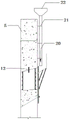
Fig. 12 is a schematic cross-sectional view of the wall 3 at the to-be-constructed section at the concrete pouring stage in the reinforcing steel bar, formwork and concrete construction process of step S106, as viewed along the extending direction of the wall. Specifically, a string pipe 20 for pouring concrete is arranged on the excavation side of the poured section of the wall 3 to be constructed through the string pipe fixing member 21, and concrete is injected into the string pipe 20 from a pouring port 22 of the string pipe 20, flows out from a bottom outlet, and then flows into the wall 3 to be constructed along an inclined template below along the wall without being poured. In some alternative embodiments, the concrete pour may also be poured directly by the pump truck. Alternatively, the concrete pour stage may employ C35P8 underwater concrete. Preferably, in the concrete pouring stage, the pouring speed of the concrete needs to be strictly controlled, particularly, phenomena such as mold expansion and mold running caused by too fast pouring are avoided, and the state of the template needs to be checked in real time. And further, after the concrete pouring is finished, performing pouring structure maintenance according to preset time. Alternatively, the curing time is, for example, not less than 7 days. And after the concrete setting strength reaches the design requirement, preparing the subsequent excavation construction of the wall body.
According to a preferred embodiment shown in fig. 13 and 14, the cross-sectional view of the wall 3 at the section to be constructed, which is obtained when the subsequent earth excavation and concrete pouring processes are performed at the preset depth in the step S107, is viewed along the extending direction of the wall, and the schematic view of the structural change of the wall 3 at the section to be constructed, which is obtained when the earth excavation and net-hanging anchor-spraying processes are performed cyclically, is shown in sequence from left to right in fig. 13 and 14.
In accordance with a preferred embodiment, a groundwater table may be encountered while continuing to excavate earth vertically downward in the manner shown in fig. 13 and 14. Therefore, when excavation is to a predetermined depth, and before subsequent excavation is performed, it is necessary to detect the water level 600 and the pressure water level 700 using a water level measuring tool, such as a luoyang shovel. Preferably, corresponding precipitation measures can be taken according to the water level detection condition, such as constructing a precipitation well. The dewatering well can achieve a good dewatering effect, the influence of underground water during wall construction is avoided, one-step wall construction can be carried out in the subsequent construction stage every 2m of excavation until the wall is finished, and the wall is approximately 500mm lower than the main structure bottom plate 24.
Particularly, after the dewatering well is constructed, the dewatering effect of the dewatering well needs to be evaluated, so that corresponding measures are taken according to the dewatering effect. In particular, precipitation effects and their corresponding measures may include:
s120: the precipitation effect is good, and normal construction is continued;
s130: the dewatering effect is poor, and a vacuum pump is used for pumping water;
s140: the dewatering well has no effect and adopts ground grouting.
According to a preferred embodiment shown in fig. 15, the cross-sectional view of the wall 3 of the section to be constructed when the vacuum pump 26 is used to pump the interlayer water 27 in step S130 is viewed along the extending direction of the wall. Specifically, although the dewatering well has a certain dewatering effect, the excavation depth gradually increases with the continuous excavation of the earth, and the interlayer water retention cannot be completely avoided during the excavation, so the interlayer water 27 can be pumped out by arranging the vacuum pump 26. Preferably, after the construction surface has no excess accumulated interlayer water 27, the subsequent wall construction is carried out.
According to a preferred embodiment shown in fig. 16, the top view of the wall 3 of the section to be constructed is shown when the ground grouting method is used to block the groundwater outside the wall in step S140. Particularly, if the precipitation effect of the precipitation well is poor and the water amount of the excavated surface is large, the construction requirement cannot be met even if the vacuum pump 26 is used for pumping water, the ground grouting treatment needs to be performed on the back of the wall body, namely on the soil facing side of the wall body 3 of the section to be constructed.
Specifically, as shown in fig. 16 and 17, a plurality of vertically arranged grouting pipes 28 are arranged in a gap-staggered manner in the poured reverse construction wall 23, that is, the soil facing side of the wall 3 to be constructed in the preset grouting range 900. In some alternative embodiments, the slip pipe 28 may be, for example, a deep hole drill rod having a gauge of a 40; the grouting range 900 is, for example, a rectangular range of about 2.5m from each of the lateral side walls of the inverted wall 23 and about 1.5m from the soil-facing side wall surface of the inverted wall 23 in the longitudinal direction. The ground grouting slurry can be, for example, cement water glass, wherein the cement is, for example, P O42.5.5 in model number. Preferably, a plurality of rows of grouting holes are arranged on the soil facing side of the poured reverse wall 23 through grouting pipes 28 for ground grouting, and the grouting holes are longitudinally spaced by 0.2m and transversely spaced by 0.8m, for example.
According to a preferred embodiment shown in fig. 18, if the poured reverse wall 23 still has a certain water seepage phenomenon, the water seepage position can be reinforced by using a local inclined grouting method as shown in fig. 18. In some alternative embodiments, the angle of inclination of the grout tube 28 is about 30 °.
It should be noted that the above-mentioned embodiments are exemplary, and that those skilled in the art, having benefit of the present disclosure, may devise various arrangements that are within the scope of the present disclosure and that fall within the scope of the invention. It should be understood by those skilled in the art that the present specification and figures are illustrative only and are not limiting upon the claims. The scope of the invention is defined by the claims and their equivalents. The present description contains several inventive concepts, such as "preferably", "according to a preferred embodiment" or "optionally", each indicating that the respective paragraph discloses a separate concept, the applicant reserves the right to submit divisional applications according to each inventive concept.
Claims (10)
1. A construction method of an enclosure structure wall under a pipeline is used for constructing an underground continuous wall (2) at a wall (3) bearing a section to be constructed with an electric packaging pipeline (1), and is characterized by at least comprising the following steps:
arranging main reinforcements (6), distribution reinforcements (11) and net hanging reinforcements (7) on the soil facing side in the wall body (3) of the section to be constructed, embedding reserved steel plates (4) on the side faces of the main reinforcements, and constructing a crown beam through the main reinforcements (6) and the net hanging reinforcements (7);
after the strength of the crown beam meets the design requirement, excavating the wall body (3) of the section to be constructed to a first preset depth, and installing a reinforcing mesh piece (8) to the soil facing side hanging mesh reinforcing steel bar (7);
performing one-time concrete spraying on the wall (3) of the section to be constructed, excavating the wall (3) of the section to be constructed to a second preset depth after the concrete strength meets the design requirement, and repeating the net hanging and anchor spraying process;
when the wall body (3) of the section to be constructed is excavated to a preset depth, connecting a plurality of distributed ribs (11) to the main rib (6), and arranging a steel frame support with a pouring hole (18) at the outer side of the distributed ribs (11) at the excavation side;
and pouring concrete into the wall body of the section to be constructed, which is not poured, of the wall body (3) through the pouring hole (18), and repeating the construction steps until the wall body (3) of the section to be constructed is excavated and poured when the strength of the concrete reaches the design requirement.
2. The method of claim 1, further comprising, prior to performing the one wall excavation: and constructing a pipeline protection structure at the position of the cross-crown beam, and chiseling reserved steel plates (4) buried at each side of the wall body (3) of the section to be constructed when the wall body is excavated once.
3. The construction method according to claim 1 or 2, characterized in that the distribution bars (11) on the excavation side and the soil-facing side are connected with the reserved steel plates (4) embedded in the wall body (3) of the section to be constructed along the two sides of the wall body along the extending direction through the respective bending parts so as to enclose the reinforcing mesh structures on the excavation side and the soil-facing side into a closed loop structure,
a plurality of distributed ribs (11) connected to the main reinforcement (6) on the soil facing side are positioned between the reinforcing mesh (8) and the main reinforcement (6).
4. The construction method according to any one of claims 1 to 3, further comprising, before continuing to excavate the wall (3) of the section to be constructed to a predetermined depth and applying concrete pouring, the steps of: the bottom inclined plane wall body of the vertical at least part of the un-poured section wall body of the wall body (3) of the section to be constructed is provided with a bottom die supporting frame formed by a steel pipe (17), a clear water template (16) is laid at the bottom of the steel pipe (17), and at least part of the main ribs (6) are reserved in the clear water template (16).
5. The construction method according to any one of claims 1 to 4, wherein before excavating the wall (3) to be constructed to a preset depth and applying concrete spraying or pouring to the excavated wall (3) to be constructed, the method further comprises: at least one water stop steel plate (12) is arranged in the wall body (3) of the section to be constructed, and two sides of the water stop steel plate (12) are connected to the reserved steel plates (4) of the wall body (3) of the section to be constructed along the two sides of the extending direction of the wall body.
6. The construction method according to any one of claims 1 to 5, wherein the steel frame support is composed of square timber (14) and channel steel (15) which are connected to each other in a staggered manner,
the square timber (14) and the channel steel (15) are arranged along two mutually perpendicular direction gaps respectively, and the two sides of the channel steel (15) are connected to reserved steel plates (4) at two ends of the soil facing side of the wall body (3) of the section to be constructed.
7. The construction method according to any one of claims 1 to 6, characterized in that at least one pouring observation hole (19) is formed in one side of the top of the steel frame support, which is far away from the pouring hole (18), and a plurality of inclined steel bar supports (13) are connected to the side surfaces of the steel frame support, and templates for pouring concrete from the outside into the wall (3) of the section to be constructed are fixed at the tail ends of the steel bar supports (13).
8. The construction method according to any one of claims 1 to 7, further comprising, while continuing to excavate the wall (3) of the section to be constructed to a predetermined depth: and detecting an underground water level in the foundation pit by using a water level measuring tool, and taking corresponding precipitation measures according to the water level measuring result, wherein the precipitation measures comprise precipitation wells.
9. The construction method according to any one of claims 1 to 8, further comprising, before the dewatering well and the next wall excavation are performed: and judging the precipitation effect of the precipitation well, and taking corresponding precipitation compensation measures according to the precipitation effect, wherein the precipitation compensation measures comprise draining interlayer stagnant water through extraction equipment and applying ground grouting on the soil facing side of the wall body (3) of the section to be constructed.
10. The construction method according to any one of claims 1 to 9, wherein the ground grouting comprises:
the soil facing side of the wall body (3) of the section to be constructed is provided with a plurality of grouting pipes (28) extending along the excavation direction in a staggered mode in a preset grouting range (900), and multiple rows of grouting holes are arranged through the grouting pipes (28) to perform ground grouting.
Priority Applications (1)
| Application Number | Priority Date | Filing Date | Title |
|---|---|---|---|
| CN202111567422.3A CN114232601B (en) | 2021-12-20 | 2021-12-20 | Construction method of lower building envelope wall of pipeline |
Applications Claiming Priority (1)
| Application Number | Priority Date | Filing Date | Title |
|---|---|---|---|
| CN202111567422.3A CN114232601B (en) | 2021-12-20 | 2021-12-20 | Construction method of lower building envelope wall of pipeline |
Publications (2)
| Publication Number | Publication Date |
|---|---|
| CN114232601A true CN114232601A (en) | 2022-03-25 |
| CN114232601B CN114232601B (en) | 2023-06-02 |
Family
ID=80759853
Family Applications (1)
| Application Number | Title | Priority Date | Filing Date |
|---|---|---|---|
| CN202111567422.3A Active CN114232601B (en) | 2021-12-20 | 2021-12-20 | Construction method of lower building envelope wall of pipeline |
Country Status (1)
| Country | Link |
|---|---|
| CN (1) | CN114232601B (en) |
Citations (6)
| Publication number | Priority date | Publication date | Assignee | Title |
|---|---|---|---|---|
| CN103603368A (en) * | 2013-11-26 | 2014-02-26 | 中铁第四勘察设计院集团有限公司 | Construction method for reverse construction of continuous wall encountering underground pipeline |
| CN205742151U (en) * | 2015-11-02 | 2016-11-30 | 中铁三局集团广东建设工程有限公司 | A kind of continuous underground wall structure of adverse construction method |
| CN111424675A (en) * | 2020-01-14 | 2020-07-17 | 中国电建集团西北勘测设计研究院有限公司 | Construction method of ultra-large pile spacing deep foundation pit supporting system |
| CN112127370A (en) * | 2020-09-11 | 2020-12-25 | 中铁十一局集团有限公司 | Reverse plugging method for non-construction fender post part of main body fender structure of station |
| CN113585272A (en) * | 2021-07-29 | 2021-11-02 | 中铁一局集团(广州)建设工程有限公司 | Pile repairing construction method for pipeline influence position by reverse construction method |
| CN215210984U (en) * | 2021-03-23 | 2021-12-17 | 安徽铁建工程有限公司 | Ride partial reverse construction method underground continuous wall of striding sewage pipe |
-
2021
- 2021-12-20 CN CN202111567422.3A patent/CN114232601B/en active Active
Patent Citations (6)
| Publication number | Priority date | Publication date | Assignee | Title |
|---|---|---|---|---|
| CN103603368A (en) * | 2013-11-26 | 2014-02-26 | 中铁第四勘察设计院集团有限公司 | Construction method for reverse construction of continuous wall encountering underground pipeline |
| CN205742151U (en) * | 2015-11-02 | 2016-11-30 | 中铁三局集团广东建设工程有限公司 | A kind of continuous underground wall structure of adverse construction method |
| CN111424675A (en) * | 2020-01-14 | 2020-07-17 | 中国电建集团西北勘测设计研究院有限公司 | Construction method of ultra-large pile spacing deep foundation pit supporting system |
| CN112127370A (en) * | 2020-09-11 | 2020-12-25 | 中铁十一局集团有限公司 | Reverse plugging method for non-construction fender post part of main body fender structure of station |
| CN215210984U (en) * | 2021-03-23 | 2021-12-17 | 安徽铁建工程有限公司 | Ride partial reverse construction method underground continuous wall of striding sewage pipe |
| CN113585272A (en) * | 2021-07-29 | 2021-11-02 | 中铁一局集团(广州)建设工程有限公司 | Pile repairing construction method for pipeline influence position by reverse construction method |
Also Published As
| Publication number | Publication date |
|---|---|
| CN114232601B (en) | 2023-06-02 |
Similar Documents
| Publication | Publication Date | Title |
|---|---|---|
| CN105155551B (en) | Pressure compensation type foundation pit supporting structure and construction method | |
| CN112554198B (en) | Construction method of deep foundation pit protection structure adjacent to high-rise building | |
| CN104264688A (en) | Manual hole digging non-uniform pile support construction technology | |
| CN104631432B (en) | Flexible supporting system for prestress anchor supporting plate of sheet-pile retaining wall and construction method thereof | |
| CN109024679A (en) | A kind of supporting and the integrated system of Pipe rack and construction method | |
| CN104631440B (en) | A kind of existing large-section in-situ concrete pile strength core increases foundation pit supporting construction and constructional method | |
| CN114775352A (en) | A kind of widening structure and construction method of existing roadbed and embankment section near the river | |
| CN107090848A (en) | A kind of ripple steel arch retaining wall | |
| CN111502691B (en) | Anti-slip tunnel structure and construction method thereof | |
| US4453366A (en) | Process of forming a continuous wall in the ground | |
| CN109972638B (en) | Construction method of prefabricated thin-wall formwork lattice beam ecological slope protection | |
| CN113417300A (en) | Slope support system and construction method thereof | |
| CN110805049B (en) | Construction method of mountain slope ultra-thickness spray anchor permanent supporting structure | |
| CN114232601A (en) | Construction method for wall of enclosing structure under pipeline | |
| CN206337566U (en) | Foundation ditch vertical prestressing anchor pole supporting construction | |
| CN213448506U (en) | Plugging structure arranged between foundation pit fender posts | |
| CN210887256U (en) | Straight combined sheet pile-ground wall-connecting type frame of water retaining cofferdam | |
| CN110670632B (en) | A kind of construction method of horizontal construction joint of side wall of underground structure reverse method | |
| CN209538212U (en) | A kind of anti-horizontal displacement radical combination soil-baffling structure | |
| CN207143970U (en) | A kind of foundation pit enclosure stake | |
| CN206279522U (en) | Ground-connecting-wall steel reinforcement cage | |
| CN114753401B (en) | Construction method for tunnel bottom karst cave treatment | |
| CN220099935U (en) | Steel pipe pile supporting structure for limited space supporting in sandy pebble area | |
| KR102596812B1 (en) | Self-supporting retaining wall system based on multi-step structure by selectively measuring of moisture | |
| CN113700004B (en) | Deep foundation pit combined support construction device and method thereof |
Legal Events
| Date | Code | Title | Description |
|---|---|---|---|
| PB01 | Publication | ||
| PB01 | Publication | ||
| SE01 | Entry into force of request for substantive examination | ||
| SE01 | Entry into force of request for substantive examination | ||
| GR01 | Patent grant | ||
| GR01 | Patent grant |