CN111179963A - Audio signal decoding and encoding apparatus and method with adaptive spectral tile selection - Google Patents
Audio signal decoding and encoding apparatus and method with adaptive spectral tile selection Download PDFInfo
- Publication number
- CN111179963A CN111179963A CN202010010552.6A CN202010010552A CN111179963A CN 111179963 A CN111179963 A CN 111179963A CN 202010010552 A CN202010010552 A CN 202010010552A CN 111179963 A CN111179963 A CN 111179963A
- Authority
- CN
- China
- Prior art keywords
- spectral
- frequency
- tile
- information
- representation
- Prior art date
- Legal status (The legal status is an assumption and is not a legal conclusion. Google has not performed a legal analysis and makes no representation as to the accuracy of the status listed.)
- Granted
Links
Images


Classifications
-
- G—PHYSICS
- G10—MUSICAL INSTRUMENTS; ACOUSTICS
- G10L—SPEECH ANALYSIS TECHNIQUES OR SPEECH SYNTHESIS; SPEECH RECOGNITION; SPEECH OR VOICE PROCESSING TECHNIQUES; SPEECH OR AUDIO CODING OR DECODING
- G10L21/00—Speech or voice signal processing techniques to produce another audible or non-audible signal, e.g. visual or tactile, in order to modify its quality or its intelligibility
- G10L21/02—Speech enhancement, e.g. noise reduction or echo cancellation
- G10L21/038—Speech enhancement, e.g. noise reduction or echo cancellation using band spreading techniques
- G10L21/0388—Details of processing therefor
-
- G—PHYSICS
- G10—MUSICAL INSTRUMENTS; ACOUSTICS
- G10L—SPEECH ANALYSIS TECHNIQUES OR SPEECH SYNTHESIS; SPEECH RECOGNITION; SPEECH OR VOICE PROCESSING TECHNIQUES; SPEECH OR AUDIO CODING OR DECODING
- G10L19/00—Speech or audio signals analysis-synthesis techniques for redundancy reduction, e.g. in vocoders; Coding or decoding of speech or audio signals, using source filter models or psychoacoustic analysis
- G10L19/008—Multichannel audio signal coding or decoding using interchannel correlation to reduce redundancy, e.g. joint-stereo, intensity-coding or matrixing
-
- G—PHYSICS
- G10—MUSICAL INSTRUMENTS; ACOUSTICS
- G10L—SPEECH ANALYSIS TECHNIQUES OR SPEECH SYNTHESIS; SPEECH RECOGNITION; SPEECH OR VOICE PROCESSING TECHNIQUES; SPEECH OR AUDIO CODING OR DECODING
- G10L19/00—Speech or audio signals analysis-synthesis techniques for redundancy reduction, e.g. in vocoders; Coding or decoding of speech or audio signals, using source filter models or psychoacoustic analysis
- G10L19/02—Speech or audio signals analysis-synthesis techniques for redundancy reduction, e.g. in vocoders; Coding or decoding of speech or audio signals, using source filter models or psychoacoustic analysis using spectral analysis, e.g. transform vocoders or subband vocoders
- G10L19/0204—Speech or audio signals analysis-synthesis techniques for redundancy reduction, e.g. in vocoders; Coding or decoding of speech or audio signals, using source filter models or psychoacoustic analysis using spectral analysis, e.g. transform vocoders or subband vocoders using subband decomposition
-
- G—PHYSICS
- G10—MUSICAL INSTRUMENTS; ACOUSTICS
- G10L—SPEECH ANALYSIS TECHNIQUES OR SPEECH SYNTHESIS; SPEECH RECOGNITION; SPEECH OR VOICE PROCESSING TECHNIQUES; SPEECH OR AUDIO CODING OR DECODING
- G10L19/00—Speech or audio signals analysis-synthesis techniques for redundancy reduction, e.g. in vocoders; Coding or decoding of speech or audio signals, using source filter models or psychoacoustic analysis
- G10L19/02—Speech or audio signals analysis-synthesis techniques for redundancy reduction, e.g. in vocoders; Coding or decoding of speech or audio signals, using source filter models or psychoacoustic analysis using spectral analysis, e.g. transform vocoders or subband vocoders
- G10L19/0212—Speech or audio signals analysis-synthesis techniques for redundancy reduction, e.g. in vocoders; Coding or decoding of speech or audio signals, using source filter models or psychoacoustic analysis using spectral analysis, e.g. transform vocoders or subband vocoders using orthogonal transformation
-
- G—PHYSICS
- G10—MUSICAL INSTRUMENTS; ACOUSTICS
- G10L—SPEECH ANALYSIS TECHNIQUES OR SPEECH SYNTHESIS; SPEECH RECOGNITION; SPEECH OR VOICE PROCESSING TECHNIQUES; SPEECH OR AUDIO CODING OR DECODING
- G10L19/00—Speech or audio signals analysis-synthesis techniques for redundancy reduction, e.g. in vocoders; Coding or decoding of speech or audio signals, using source filter models or psychoacoustic analysis
- G10L19/02—Speech or audio signals analysis-synthesis techniques for redundancy reduction, e.g. in vocoders; Coding or decoding of speech or audio signals, using source filter models or psychoacoustic analysis using spectral analysis, e.g. transform vocoders or subband vocoders
- G10L19/022—Blocking, i.e. grouping of samples in time; Choice of analysis windows; Overlap factoring
- G10L19/025—Detection of transients or attacks for time/frequency resolution switching
-
- G—PHYSICS
- G10—MUSICAL INSTRUMENTS; ACOUSTICS
- G10L—SPEECH ANALYSIS TECHNIQUES OR SPEECH SYNTHESIS; SPEECH RECOGNITION; SPEECH OR VOICE PROCESSING TECHNIQUES; SPEECH OR AUDIO CODING OR DECODING
- G10L19/00—Speech or audio signals analysis-synthesis techniques for redundancy reduction, e.g. in vocoders; Coding or decoding of speech or audio signals, using source filter models or psychoacoustic analysis
- G10L19/02—Speech or audio signals analysis-synthesis techniques for redundancy reduction, e.g. in vocoders; Coding or decoding of speech or audio signals, using source filter models or psychoacoustic analysis using spectral analysis, e.g. transform vocoders or subband vocoders
- G10L19/028—Noise substitution, i.e. substituting non-tonal spectral components by noisy source
-
- G—PHYSICS
- G10—MUSICAL INSTRUMENTS; ACOUSTICS
- G10L—SPEECH ANALYSIS TECHNIQUES OR SPEECH SYNTHESIS; SPEECH RECOGNITION; SPEECH OR VOICE PROCESSING TECHNIQUES; SPEECH OR AUDIO CODING OR DECODING
- G10L19/00—Speech or audio signals analysis-synthesis techniques for redundancy reduction, e.g. in vocoders; Coding or decoding of speech or audio signals, using source filter models or psychoacoustic analysis
- G10L19/02—Speech or audio signals analysis-synthesis techniques for redundancy reduction, e.g. in vocoders; Coding or decoding of speech or audio signals, using source filter models or psychoacoustic analysis using spectral analysis, e.g. transform vocoders or subband vocoders
- G10L19/03—Spectral prediction for preventing pre-echo; Temporary noise shaping [TNS], e.g. in MPEG2 or MPEG4
-
- G—PHYSICS
- G10—MUSICAL INSTRUMENTS; ACOUSTICS
- G10L—SPEECH ANALYSIS TECHNIQUES OR SPEECH SYNTHESIS; SPEECH RECOGNITION; SPEECH OR VOICE PROCESSING TECHNIQUES; SPEECH OR AUDIO CODING OR DECODING
- G10L19/00—Speech or audio signals analysis-synthesis techniques for redundancy reduction, e.g. in vocoders; Coding or decoding of speech or audio signals, using source filter models or psychoacoustic analysis
- G10L19/02—Speech or audio signals analysis-synthesis techniques for redundancy reduction, e.g. in vocoders; Coding or decoding of speech or audio signals, using source filter models or psychoacoustic analysis using spectral analysis, e.g. transform vocoders or subband vocoders
- G10L19/032—Quantisation or dequantisation of spectral components
-
- G—PHYSICS
- G10—MUSICAL INSTRUMENTS; ACOUSTICS
- G10L—SPEECH ANALYSIS TECHNIQUES OR SPEECH SYNTHESIS; SPEECH RECOGNITION; SPEECH OR VOICE PROCESSING TECHNIQUES; SPEECH OR AUDIO CODING OR DECODING
- G10L19/00—Speech or audio signals analysis-synthesis techniques for redundancy reduction, e.g. in vocoders; Coding or decoding of speech or audio signals, using source filter models or psychoacoustic analysis
- G10L19/04—Speech or audio signals analysis-synthesis techniques for redundancy reduction, e.g. in vocoders; Coding or decoding of speech or audio signals, using source filter models or psychoacoustic analysis using predictive techniques
- G10L19/06—Determination or coding of the spectral characteristics, e.g. of the short-term prediction coefficients
-
- G—PHYSICS
- G10—MUSICAL INSTRUMENTS; ACOUSTICS
- G10L—SPEECH ANALYSIS TECHNIQUES OR SPEECH SYNTHESIS; SPEECH RECOGNITION; SPEECH OR VOICE PROCESSING TECHNIQUES; SPEECH OR AUDIO CODING OR DECODING
- G10L19/00—Speech or audio signals analysis-synthesis techniques for redundancy reduction, e.g. in vocoders; Coding or decoding of speech or audio signals, using source filter models or psychoacoustic analysis
- G10L19/04—Speech or audio signals analysis-synthesis techniques for redundancy reduction, e.g. in vocoders; Coding or decoding of speech or audio signals, using source filter models or psychoacoustic analysis using predictive techniques
- G10L19/16—Vocoder architecture
- G10L19/18—Vocoders using multiple modes
-
- G—PHYSICS
- G10—MUSICAL INSTRUMENTS; ACOUSTICS
- G10L—SPEECH ANALYSIS TECHNIQUES OR SPEECH SYNTHESIS; SPEECH RECOGNITION; SPEECH OR VOICE PROCESSING TECHNIQUES; SPEECH OR AUDIO CODING OR DECODING
- G10L21/00—Speech or voice signal processing techniques to produce another audible or non-audible signal, e.g. visual or tactile, in order to modify its quality or its intelligibility
- G10L21/02—Speech enhancement, e.g. noise reduction or echo cancellation
- G10L21/038—Speech enhancement, e.g. noise reduction or echo cancellation using band spreading techniques
-
- G—PHYSICS
- G10—MUSICAL INSTRUMENTS; ACOUSTICS
- G10L—SPEECH ANALYSIS TECHNIQUES OR SPEECH SYNTHESIS; SPEECH RECOGNITION; SPEECH OR VOICE PROCESSING TECHNIQUES; SPEECH OR AUDIO CODING OR DECODING
- G10L25/00—Speech or voice analysis techniques not restricted to a single one of groups G10L15/00 - G10L21/00
- G10L25/03—Speech or voice analysis techniques not restricted to a single one of groups G10L15/00 - G10L21/00 characterised by the type of extracted parameters
- G10L25/06—Speech or voice analysis techniques not restricted to a single one of groups G10L15/00 - G10L21/00 characterised by the type of extracted parameters the extracted parameters being correlation coefficients
-
- G—PHYSICS
- G10—MUSICAL INSTRUMENTS; ACOUSTICS
- G10L—SPEECH ANALYSIS TECHNIQUES OR SPEECH SYNTHESIS; SPEECH RECOGNITION; SPEECH OR VOICE PROCESSING TECHNIQUES; SPEECH OR AUDIO CODING OR DECODING
- G10L25/00—Speech or voice analysis techniques not restricted to a single one of groups G10L15/00 - G10L21/00
- G10L25/03—Speech or voice analysis techniques not restricted to a single one of groups G10L15/00 - G10L21/00 characterised by the type of extracted parameters
- G10L25/18—Speech or voice analysis techniques not restricted to a single one of groups G10L15/00 - G10L21/00 characterised by the type of extracted parameters the extracted parameters being spectral information of each sub-band
-
- G—PHYSICS
- G10—MUSICAL INSTRUMENTS; ACOUSTICS
- G10L—SPEECH ANALYSIS TECHNIQUES OR SPEECH SYNTHESIS; SPEECH RECOGNITION; SPEECH OR VOICE PROCESSING TECHNIQUES; SPEECH OR AUDIO CODING OR DECODING
- G10L25/00—Speech or voice analysis techniques not restricted to a single one of groups G10L15/00 - G10L21/00
- G10L25/03—Speech or voice analysis techniques not restricted to a single one of groups G10L15/00 - G10L21/00 characterised by the type of extracted parameters
- G10L25/21—Speech or voice analysis techniques not restricted to a single one of groups G10L15/00 - G10L21/00 characterised by the type of extracted parameters the extracted parameters being power information
-
- H—ELECTRICITY
- H03—ELECTRONIC CIRCUITRY
- H03M—CODING; DECODING; CODE CONVERSION IN GENERAL
- H03M7/00—Conversion of a code where information is represented by a given sequence or number of digits to a code where the same, similar or subset of information is represented by a different sequence or number of digits
- H03M7/30—Compression; Expansion; Suppression of unnecessary data, e.g. redundancy reduction
-
- G—PHYSICS
- G10—MUSICAL INSTRUMENTS; ACOUSTICS
- G10L—SPEECH ANALYSIS TECHNIQUES OR SPEECH SYNTHESIS; SPEECH RECOGNITION; SPEECH OR VOICE PROCESSING TECHNIQUES; SPEECH OR AUDIO CODING OR DECODING
- G10L19/00—Speech or audio signals analysis-synthesis techniques for redundancy reduction, e.g. in vocoders; Coding or decoding of speech or audio signals, using source filter models or psychoacoustic analysis
- G10L19/02—Speech or audio signals analysis-synthesis techniques for redundancy reduction, e.g. in vocoders; Coding or decoding of speech or audio signals, using source filter models or psychoacoustic analysis using spectral analysis, e.g. transform vocoders or subband vocoders
- G10L19/0204—Speech or audio signals analysis-synthesis techniques for redundancy reduction, e.g. in vocoders; Coding or decoding of speech or audio signals, using source filter models or psychoacoustic analysis using spectral analysis, e.g. transform vocoders or subband vocoders using subband decomposition
- G10L19/0208—Subband vocoders
-
- H—ELECTRICITY
- H04—ELECTRIC COMMUNICATION TECHNIQUE
- H04S—STEREOPHONIC SYSTEMS
- H04S1/00—Two-channel systems
- H04S1/007—Two-channel systems in which the audio signals are in digital form
Landscapes
- Engineering & Computer Science (AREA)
- Physics & Mathematics (AREA)
- Acoustics & Sound (AREA)
- Multimedia (AREA)
- Signal Processing (AREA)
- Computational Linguistics (AREA)
- Audiology, Speech & Language Pathology (AREA)
- Human Computer Interaction (AREA)
- Health & Medical Sciences (AREA)
- Spectroscopy & Molecular Physics (AREA)
- Quality & Reliability (AREA)
- Mathematical Physics (AREA)
- Theoretical Computer Science (AREA)
- Compression, Expansion, Code Conversion, And Decoders (AREA)
- Stereophonic System (AREA)
Abstract
The present invention relates to an audio signal decoding and encoding apparatus and method with adaptive spectral tile selection. An apparatus for decoding an encoded signal comprising: an audio decoder (1102), the audio decoder (1102) being configured to decode the encoded representation of the first set of first spectral portions to obtain a decoded first set of first spectral portions (1101); a parametric decoder (1104), the parametric decoder (1104) being configured to decode the encoded parametric representation of the second set of second spectral portions to obtain a decoded representation of the parametric representation (1103), wherein the parametric information comprises for each target frequency tile a source region identification as matching information; and a frequency regenerator (1106), the frequency regenerator (1106) for regenerating the target frequency tile using the source region from the first set of first spectral portions (1101) identified by the matching information.
Description
The present patent application is a divisional application of the patent application entitled "apparatus and method for decoding and encoding an audio signal using adaptive spectral tile selection" filed as international application date 2014, 7/15, national application number 201480041566.7.
Technical Field
The present invention relates to audio encoding/decoding, and in particular to audio encoding using intelligent gap filling.
Background
Audio coding is a field of signal compression that uses psychoacoustic knowledge to deal with redundant and irrelevant parts in an audio signal. Today audio codecs typically require around 60 kbps/channel to perceptually transparently encode almost any type of audio signal. Newer codecs aim to reduce the coding bit rate by exploiting spectral similarities in the signal using techniques such as bandwidth extension (BWE). The BWE scheme uses a low bit-rate parameter set to represent the High Frequency (HF) components of the audio signal. The HF spectrum is filled with spectral content from the Low Frequency (LF) region, and the spectral shape, tilt and temporal continuity are adjusted to maintain the timbre and timbre of the original signal. Such a BWE method enables the audio codec to maintain good quality even at low bit rates of about 24 kbps/channel.
The storage or transmission of audio signals is often subject to strict bit rate constraints. In the past, encoders were forced to reduce the transmitted audio bandwidth substantially only when a very low bit rate was available.
Modern audio codecs are now able to encode wideband signals by using the bandwidth extension (BWE) method [1 ]. These algorithms rely on the application of parametric representations of the high frequency content (HF), which are generated by means of the transfer of the waveform-coded low frequency part (LF) of the decoded signal into the HF spectral region ("patching"), and parameter-driven post-processing. According to BWE schemes, the reconstruction of HF spectral regions above a given so-called crossover frequency is usually based on spectral patching. Typically, the HF region includes a plurality of adjacent patches, and each of these patches originates from a Bandpass (BP) region of the LF spectrum below a given crossover frequency. Prior art systems efficiently perform patching within a filter bank representation, e.g., a quadrature mirror filter bank (QMF), by copying a set of neighboring subband coefficients from a source region to a target region.
Another technique found in today's audio codecs to improve compression efficiency, thereby enabling the audio bandwidth to be extended at low bit rates, is parametric driven synthesis replacement of the appropriate part of the audio spectrum. For example, the noise-like signal portion of the original audio signal may be replaced by artificial noise generated in the decoder and scaled by the side information parameters, without substantially losing subjective quality. One example is the Perceptual Noise Substitution (PNS) tool [5] included in MPEG-4 Advanced Audio Coding (AAC).
Another technique is also provided that also enables bandwidth extension at low bit rates, which is a noise filling technique included in MPEG-D Unified Speech and Audio Coding (USAC) [7 ]. The spectral gaps (zeros) derived by the dead zone of the quantizer due to too coarse quantization are then filled with artifacts in the decoder and scaled by parameter driven post-processing.
Another prior art system is called Accurate Spectral Replacement (ASR) [2-4 ]. In addition to waveform codecs, ASR also employs dedicated signal synthesis segments that recover the perceptually important sinusoidal part of the signal at the decoder. Furthermore, the system described in [5] relies on sinusoidal modeling in the HF region of the waveform coder so that the extended audio bandwidth still has a good perceptual quality at low bit rates. All these methods involve a transformation of the data into a second domain other than the Modified Discrete Cosine Transform (MDCT) and also involve rather complex analysis/synthesis segments for preserving the HF sine components.
Fig. 13A shows a schematic diagram of an audio encoder for bandwidth extension techniques as used in, for example, high-efficiency advanced audio coding (HE-ACC). The audio signal at line 1300 is input to a filter system that includes a low pass 1302 and a high pass 1304. The signal output through the high-pass filter 1304 is input to a parameter extractor/encoder 1306. For example, the parameter extractor/encoder 1306 is configured to calculate and encode parameters such as spectral envelope parameters, noise addition parameters, missing harmonic parameters, or inverse filter parameters. These extracted parameters are input to a bitstream multiplexer 1308. The low pass output signal is input to a processor that generally includes the functionality of the down sampler 1310 and the core encoder 1312. The low pass 1302 limits the bandwidth to be encoded to a significantly smaller bandwidth than the bandwidth present in the original input audio signal present on line 1300. This provides significant coding gain due to the fact that: all functions present in the core encoder only have to operate on signals with reduced bandwidth. When the bandwidth of the audio signal on e.g. line 1300 is 20kHz and when the low-pass filter 1302 has a bandwidth of e.g. 4kHz, in order to satisfy the sampling theorem it is in theory sufficient that the sampling frequency of the signal after the down-sampler is 8kHz, which is substantially reduced to the sampling rate required for the audio signal 1300 which must be at least 40 kHz.
Fig. 13B shows a schematic diagram of a corresponding bandwidth extension decoder. The decoder includes a bitstream demultiplexer 1320. The bitstream demultiplexer 1320 extracts an input signal of the core decoder 1322 and an input signal of the parameter decoder 1324. In the above example, the sampling rate of the core decoder output signal is 8kHz and thus the bandwidth is 4kHz, however, to complete the bandwidth reconstruction, the output signal of the high frequency reconstructor 1330 must be at 20kHz, which requires a sampling rate of at least 40 kHz. To make this possible, a decoder processor having the functions of the upsampler 1325 and the filter bank 1326 is required. Then, the high frequency reconstructor 1330 receives the frequency analyzed low frequency signal output by the filter bank 1326 and reconstructs the frequency range defined by the high pass filter 1304 of fig. 13A using the parameterized representation of the high frequency band. The high frequency reconstructor 1330 has several functions such as the function of regenerating the upper frequency range using the source range in the low frequency range, spectral envelope adjustment, noise addition, and introducing missing harmonics within the upper frequency range, and also includes an inverse filtering operation if applied and calculated in the encoder of fig. 13A in order to explain the fact that the higher frequency range usually has a different pitch than the lower frequency range. In HE-ACC, the missing harmonics are resynthesized on the decoder side and placed exactly in the middle of the reconstruction band. Thus, all missing harmonic lines determined in a certain reconstruction band are not placed at their frequency values located in the original signal. Instead, those missing harmonic lines are placed at frequencies at the center of a certain frequency band. Thus, when a missing harmonic line in the original signal is placed very close to the reconstructed band boundary in the original signal, the error in frequency introduced by placing this missing harmonic line in the reconstructed signal at the center of the band is close to 50% of the individual reconstructed band in which the parameters were generated and transmitted.
Furthermore, although a typical audio core encoder operates in the spectral domain, the core decoder generates a time-domain signal, which is then converted again to the spectral domain by the filter bank 1326 function. This introduces additional processing delays, which may introduce artefacts due to the serial process of first transforming from the spectral domain into the frequency domain and again into a generally different frequency domain, and of course this also requires a significant amount of computational complexity and hence electrical power, which is particularly a problem when the bandwidth extension technique is applied to mobile devices such as mobile phones, tablets or laptops, etc.
Current audio codecs use BWE as the main part of the coding scheme to perform low bit rate audio coding. However, BWE techniques are limited to replacing only High Frequency (HF) content. Furthermore, they do not enable perceptually important content above a given crossover frequency to be waveform coded. Therefore, contemporary audio codecs lose HF details or timbre when BWE is implemented, since in most systems the exact alignment of the pitch harmonics of the signal is not considered.
Another drawback of the current state of the art BWE systems is the need to transform the audio signal into a new domain to achieve BWE (e.g. from MDCT domain to QMF domain). This results in synchronization complexity, additional computational complexity, and increased storage requirements.
Generally, bandwidth extension schemes use spectral patching for the purpose of reconstructing a high frequency spectral region above a given so-called crossover frequency. The HF-zone comprises a plurality of adjacent patches, and each of these patches originates from the same band-pass region of the low-frequency spectrum below a given crossover frequency. Within the filter bank representation of the signal, such a system copies a set of adjacent subband coefficients in the low frequency spectrum into the HF region. The boundaries of the selected set are generally system dependent and signal independent. For some signal content, such static patching choices may result in poor timbre and coloration of the reconstructed signal.
Other methods convey the LF signals to the HF zone by signal adaptive Single Sideband (SSB) modulation. Such an approach is computationally complex compared to the replication process, since it operates on time domain signals at a high sampling rate.
Furthermore, the patching may be unstable, especially for non-tonal signals such as unvoiced speech. Therefore, known patching schemes may cause damage to the audio signal.
Disclosure of Invention
It is an object of the invention to provide an improved encoding/decoding concept resulting in a better audio quality.
This object is achieved by a decoding device, an encoding device, an audio decoding method, or a storage medium having a computer program stored thereon.
Yet another aspect is based on the discovery that: impairments in audio quality can be compensated for by applying a signal adaptive frequency tile filling scheme. To this end, an analysis is performed on the encoder side to find the best matching candidate source region for a certain target region. Matching information identifying a certain source region for the target region is generated together with optionally some additional information and sent as side information to the decoder. The decoder then uses the matching information to apply a frequency tile filling operation. To this end, the decoder reads matching information from the transmitted data stream or data file and accesses a source region identified for a certain reconstruction band and, if indicated in the matching information, additionally performs a certain processing of the source region data to generate the original spectral data of the reconstruction band. The result of the frequency tile filling operation, i.e. the original spectral data of the reconstructed band, is then shaped using the spectral envelope information to finally obtain a reconstructed band comprising a first spectral portion, e.g. a tonal portion. However, these tonal portions are not generated by the adaptive tile-filling scheme, but these first spectral portions are directly output by the audio decoder or the core decoder.
The adaptive spectral tile selection scheme may operate with low granularity. In this implementation, the source region is subdivided into generally overlapping source regions, and the target region or reconstruction band is given by a non-overlapping frequency target region. Then, a similarity between each source region and each target region is determined at the encoder side and a best matching pair of the source region and the target region is identified by matching information, and at the decoder side, the source region identified in the matching information is used to generate original spectral data of a reconstructed frequency band.
For the purpose of achieving higher granularity, each source region is allowed to shift to achieve some hysteresis where the degree of similarity is greatest. This lag may be as fine as a bin and allows an even better match between the source and target regions.
Furthermore, in addition to identifying only the best matching pair, the correlation lag may also be transmitted within the matching information, and additionally, even the symbols may be transmitted. When the sign is determined to be negative on the encoder side, a corresponding sign flag is also sent within the match information, while on the decoder side the source region spectral values are multiplied by "-1", or in a complex representation the source region spectral values are "rotated" by 180 °.
Yet another implementation of the present invention applies a tile whitening operation. Whitening of the spectrum removes coarse spectral envelope information and emphasizes the spectral fine structure of most interest for evaluating tile similarity. Thus, the frequency tiles are whitened on the one hand and/or the source signal is whitened on the other hand before the cross-correlation measure is calculated. When only the tile is whitened using a predetermined procedure, a whitening flag is sent indicating to the decoder that the same predetermined whitening process should be applied to the frequencies within the IGF.
With respect to tile selection, the regenerated spectrum is preferably spectrally shifted by an integer number of transform bins using hysteresis of correlation. Depending on the underlying transform, the spectral shift may require additive correlation. In the case of odd lags, the tile is additionally modulated by multiplication by an alternating time sequence-1/1 to compensate for the frequency-reversed representation of each other band within the MDCT. Further, the sign of the correlation result is applied when generating the frequency tile.
Furthermore, tile pruning and stabilization is preferably used to ensure that artifacts caused by rapidly changing source regions of the same reconstruction region or target region are avoided. To this end, a similarity analysis between different identified source regions is performed, and when a source tile is similar to other source tiles with a similarity above a threshold, then the source tile may be discarded from a set of potential source tiles as it is highly correlated with other source tiles. Furthermore, as a tile selection stabilization, if none of the source tiles in the current frame correlate to the target tiles in the current frame (better than a given threshold), then the tile order from the previous frame is preferably maintained.
Another aspect is based on the following findings: the audio quality of the reconstructed signal can be improved by IGF since the entire spectrum is accessible to the core encoder, so that, for example, perceptually important tonal parts in the high spectral range can still be encoded by the core encoder instead of being parametrically replaced. In addition, a gap-filling operation is performed using frequency tiles from a first set of first spectral portions, e.g. a set of tonal portions that are typically from a lower frequency range but may also be from a higher frequency range if available. However, for performing spectral envelope adjustment on the encoder side, spectral portions from the first set of spectral portions located in the reconstructed frequency band are not further post-processed by, for example, spectral envelope adjustment. Only the remaining spectral values in the reconstructed frequency band that do not originate from the core encoder are envelope adjusted using the envelope information. Preferably, the envelope information is full band envelope information including energy of a first set of first spectral portions in a reconstruction band and a second set of second spectral portions in the same reconstruction band, wherein later spectral values in the second set of second spectral portions are indicated as zero and are therefore not encoded by the core encoder but parametrically encoded using the low resolution energy information.
It has been found that either the normalized absolute energy values or the non-normalized absolute energy values with respect to the bandwidth of the respective frequency band are useful and very efficient for the decoder side application. This applies in particular when the gain factor has to be calculated based on residual energy in the reconstructed band, missing energy in the reconstructed band and frequency tile information in the reconstructed band.
Furthermore, it is preferable that the encoded bitstream includes not only energy information of the reconstruction band but also a scale factor of a scale factor band extending up to a maximum frequency in addition. This ensures that for each reconstructed frequency band available for a particular tonal portion, i.e. the first spectral portion, the first set of first spectral portions can actually be decoded with the appropriate amplitude. Furthermore, in addition to the scale factor for each reconstructed band, the energy of that reconstructed band is generated in the encoder and transmitted to the decoder. Furthermore, it is preferable that the reconstruction band coincides with the scale factor band, or in the case of energy grouping, at least the boundary of the reconstruction band coincides with the boundary of the scale factor band.
Another aspect is based on the following findings: the problems related to the separation of bandwidth extension on the one hand and core coding on the other hand can be solved and overcome by performing bandwidth extension in the same spectral domain in which the core decoder operates. Thus, a full rate core decoder is provided that encodes and decodes a full audio signal range. This does not require a down-sampler at the encoder side and an up-sampler at the decoder side. Alternatively, the entire processing is performed in the full sampling rate or full bandwidth domain. In order to obtain a high coding gain, the audio signal is analyzed to find a first set of first spectral portions that have to be encoded with a high resolution, wherein in an embodiment the first set of first spectral portions may comprise tonal portions of the audio signal. On the other hand, non-tonal or noisy components of the audio signal constituting the second set of second spectral portions are parametrically encoded at a low spectral resolution. The encoded audio signal then only requires a first set of first spectral portions that are encoded in a waveform preserving manner at a high spectral resolution and additionally a second set of second spectral portions that are parametrically encoded at a low resolution using frequency "tiles" derived from the first set. At the decoder side, the core decoder, which is a full-band decoder, reconstructs the first set of first spectral portions in a waveform-preserving manner, i.e. without knowing that there is any additional frequency regeneration. However, the spectrum thus generated has many spectral gaps. These gaps are then filled with the intelligent gap-filling (IGF) technique of the invention using, on the one hand, frequency regeneration applying parametric data and, on the other hand, the source spectral range, i.e. the first spectral portion reconstructed by the full-rate audio decoder.
In a further embodiment, the spectral portions reconstructed only by noise filling and not bandwidth replication or frequency tile filling comprise a third set of third spectral portions. Due to the fact that the present coding concept operates in a single domain for core coding/decoding on the one hand and in a single domain for frequency regeneration on the other hand, IGF is not only limited to filling higher frequency ranges, but also lower frequency ranges, by noise filling without frequency regeneration or by frequency regeneration using spectral tiles at different frequency ranges.
Furthermore, it is emphasized that the information on the spectral energy, the information on the individual energy or the individual energy information, the information on the residual energy or the residual energy information, the information on the tile energy or the tile energy information, or the information on the lost energy or the lost energy information may comprise not only energy values but also (e.g. absolute) amplitude values, level values or any other values, from which a final energy value may be derived. Thus, the information about the energy may comprise, for example, the energy value itself and/or the value of the level and/or the value of the amplitude and/or the value of the absolute amplitude.
Yet another aspect is based on the discovery that: the correlation situation is important not only for the source range but also for the target range. Furthermore, the present invention recognizes the following: different correlation situations may occur in the source range and the target range. For example, when considering a speech signal with high frequency noise, the situation may be: when the speaker is placed in the middle, the low frequency band including the voice signal having a small number of overtones is highly correlated in the left channel and the right channel. However, the high frequency part may be strongly uncorrelated due to the fact that there may be different high frequency noise on the left side compared to other high frequency noise or no high frequency noise on the right side. Thus, when a simple gap-filling operation can be performed that ignores this, then the high frequency part will also be relevant, and this may generate severe spatially isolated artefacts in the reconstructed signal. To solve this problem, parametric data of the reconstructed frequency band or of a second set of second spectral portions, which usually have to be reconstructed using the first set of first spectral portions, are calculated to identify the second spectral portions or a first binaural representation or a different second binaural representation of the differently stated reconstructed frequency band. Thus, on the encoder side, a binaural cue is calculated for the second spectral portion, i.e. for the portion where the energy information of the reconstruction band is additionally calculated. The decoder-side frequency regenerator then regenerates the second spectral portion from the first set of first spectral portions, i.e. the first portion in the source range, and parametric data of the second portion, e.g. spectral envelope energy information or any other spectral envelope data, and additionally from the binaural identification of the second portion, i.e. the reconstructed band in case of reconsideration.
Preferably, the binaural identification is sent as a flag for each reconstruction band, and the data is sent from the encoder to the decoder, which then decodes the core signal as indicated by the preferably calculated flag for the core band. Thus, in one implementation, the core signal is stored in two stereo representations (e.g., left/right and mid/side) and for IGF frequency tile filling, the source tile representation is selected to match the target tile representation as indicated by the two-channel identification flag for the intelligent gap filling or reconstruction band, i.e., for the target range.
It is emphasized that this process works not only for stereo signals, i.e. for left and right channels, but also for multi-channel signals. In the case of a multi-channel signal, several pairs of different channels, e.g. a left channel and a right channel, as a first pair, a left surround channel and a right surround channel as a second pair and a center channel and an LFE channel as a third pair, may be processed in this way. Other pairs may be determined for higher output channel formats, such as 7.1, 11.1, etc.
Another aspect is based on the following findings: improved quality and reduced bit rate are obtained by combining Temporal Noise Shaping (TNS) or time-slice shaping (TTS) techniques with high frequency reconstruction, improving quality and reducing bit rate, particularly for signals comprising transient parts that often occur in audio signals. The TNS/TTS processing on the encoder side, which is implemented by prediction with respect to frequency, reconstructs the temporal envelope of the audio signal. Depending on the implementation, i.e. when the temporal noise shaping filter is determined within a frequency range that includes not only the source frequency range but also the target frequency range to be reconstructed in the frequency regenerative decoder, the temporal envelope is applied not only to the core audio signal up to the gap filling start frequency but also to the spectral range of the reconstructed second spectral portion. Thus, pre-echoes and post-echoes that occur without the use of time-slice shaping are reduced or eliminated. This is done by applying an inverse prediction with respect to frequency not only in the core frequency range up to a certain gap filling start frequency but also in frequency ranges above the core frequency range. For this purpose, frequency regeneration or frequency tile generation is performed at the decoder side before applying the prediction on the frequency. However, depending on whether the energy information calculation is performed on the spectral residual values after filtering or on the (full) spectral values before envelope shaping, the prediction on frequency may be applied before or after spectral envelope shaping.
TTS processing on one or more frequency tiles additionally establishes continuity of correlation between the source range and the reconstruction range or within two adjacent reconstruction ranges or frequency tiles.
According to one implementation, complex TNS/TTS filtering is preferably used. Thereby, (time) aliasing artifacts like MDCT are avoided for the real representation of the critical samples. By applying not only the modified discrete cosine transform but also the modified discrete sine transform, it is possible to compute a complex TNS filter on the encoder side in addition to obtaining the complex modified transform. However, only the modified discrete cosine transform values, i.e. the real part of the complex transform, are transmitted. However, on the decoder side, the MDCT spectrum of a previous or subsequent frame may be used to estimate the imaginary part of the transform such that on the decoder side, the complex filter may be applied again in inverse prediction with respect to frequency, in particular in prediction with respect to the boundary between the source range and the reconstruction range and also with respect to the boundary between frequency-adjacent frequency tiles within the reconstruction range.
The audio coding system of the present invention efficiently encodes an arbitrary audio signal at a wide range of bit rates. However, for high bit rates, the system of the present invention converges on transparency, and for low bit rates, minimizes perceptual annoyance. Thus, a major share of the available bit rate is used for waveform coding in the encoder only the perceptually most relevant structure of the signal, and the resulting spectral gaps are filled in the decoder with signal content that approximately approximates the original spectrum. A very limited bit budget is consumed to control parameter driven so-called spectral Intelligent Gap Filling (IGF) by dedicated side information sent from the encoder to the decoder.
Drawings
Preferred embodiments of the present invention are described subsequently with reference to the accompanying drawings, in which:
fig. 1A shows an apparatus for encoding an audio signal;
FIG. 1B shows a decoder for decoding an encoded audio signal matched to the encoder of FIG. 1A;
figure 2A shows a preferred implementation of a decoder;
FIG. 2B shows a preferred implementation of an encoder;
fig. 3A shows a schematic representation of a spectrum generated by the spectral domain decoder of fig. 1B;
FIG. 3B shows a table representing the relationship between the scale factors of the scale factor bands and the energy used to reconstruct the bands and the noise fill information of the noise fill bands;
fig. 4A illustrates the functionality of the spectral domain encoder for applying a selection of spectral portions to a first set of spectral portions and a second set of spectral portions;
FIG. 4B illustrates an implementation of the functionality of FIG. 4A;
FIG. 5A illustrates the functionality of an MDCT encoder;
FIG. 5B illustrates the functionality of a decoder using MDCT techniques;
FIG. 5C illustrates an implementation of a frequency regenerator;
FIG. 6A shows an audio encoder with temporal noise shaping/time-slice shaping functionality;
FIG. 6B illustrates a decoder using temporal noise shaping/time-tiling shaping techniques;
fig. 6C shows a further function with a different order of spectral prediction filter and spectral shaper of the temporal noise shaping/temporal tile shaping function;
FIG. 7A illustrates an implementation of a time-slice shaping (TTS) function;
FIG. 7B shows a decoder implementation matched to the encoder implementation of FIG. 7A;
FIG. 7C shows a spectral representation of an original signal and an extended signal without TTS;
FIG. 7D illustrates a frequency representation showing a correspondence between intelligent gap-filling frequency and time-slice shaping energy;
fig. 7E shows a spectral diagram of an original signal and an extended signal with TTS;
fig. 8A shows a binaural decoder with frequency reproduction;
FIG. 8B shows a table showing different combinations of representations and source/destination scopes;
FIG. 8C shows a flow chart illustrating the function of a binaural decoder with frequency reproduction of FIG. 8A;
FIG. 8D shows a more detailed implementation of the decoder of FIG. 8A;
FIG. 8E shows an implementation of an encoder for binaural processing to be decoded by the decoder of FIG. 8A;
FIG. 9A illustrates a decoder having a frequency regeneration technique that uses energy values of a regeneration frequency range;
FIG. 9B shows a more detailed implementation of the frequency regenerator of FIG. 9A;
FIG. 9C shows a schematic diagram illustrating the functionality of FIG. 9B;
FIG. 9D illustrates yet another implementation of the decoder of FIG. 9B;
FIG. 10A shows a block diagram of an encoder matched to the decoder of FIG. 9A;
FIG. 10B shows a block diagram illustrating yet another function of the parameter calculator of FIG. 10A;
FIG. 10C shows a block diagram illustrating yet another function of the parameterized calculator of FIG. 10A;
FIG. 10D shows a block diagram of yet another function of the parameterized calculator of FIG. 10A;
FIG. 11A shows yet another decoder with a specific source range identification for a spectral tiling operation in the decoder;
FIG. 11B illustrates yet another function of the frequency regenerator of FIG. 11A;
FIG. 11C shows an encoder for use in cooperation with the decoder of FIG. 11A;
FIG. 11D shows a block diagram of an implementation of the parameter calculator of FIG. 11C;
FIGS. 12A and 12B show frequency diagrams illustrating source and target ranges;
FIG. 12C shows a graph of an exemplary correlation of two signals;
FIG. 13A shows a prior art encoder with bandwidth extension; and
fig. 13B shows a prior art decoder with bandwidth extension.
Detailed Description
Fig. 1A shows an apparatus for encoding an audio signal 99. The audio signal 99 is input to a time-to-spectrum converter 100, the time-to-spectrum converter 100 being adapted to convert the audio signal having the sampling rate into a spectral representation 101 output by the time-to-spectrum converter. The spectrum 101 is input to a spectrum analyzer 102 for analyzing the spectral representation 101. The spectrum analyzer 101 is configured to determine a first set of first spectral portions 103 to be encoded at a first spectral resolution and a second, different set of second spectral portions 105 to be encoded at a second spectral resolution. The second spectral resolution is less than the first spectral resolution. The second set of second spectral portions 105 is input to a parameter calculator or parametric encoder 104 for calculating spectral envelope information having a second spectral resolution. Furthermore, the spectral domain audio encoder 106 is arranged for generating a first encoded representation 107 of a first set of first spectral portions having a first spectral resolution. Furthermore, the parameter calculator/parametric encoder 104 is configured for generating a second encoded representation 109 of a second set of second spectral portions. The first and second encoded representations 107, 109 are input to a bitstream multiplexer or a bitstream former 108, and the block 108 ultimately outputs the encoded audio signal for transmission or storage on a storage device.
Typically, a first spectral portion, such as 306 of fig. 3A, would be surrounded by two second spectral portions, such as 307A and 307B. This is not the case in HE AAC, where the core encoder frequency range is band limited.
Fig. 1B shows a decoder matched to the encoder of fig. 1A. The first encoded representation 107 is input to a spectral domain audio decoder 112 for generating a first decoded representation of the first set of first spectral portions, the decoded representation having a first spectral resolution. Furthermore, the second encoded representation 109 is input to a parametric decoder 114 for generating a second decoded representation of a second set of second spectral portions having a second spectral resolution lower than the first spectral resolution.
The decoder further comprises a frequency regenerator 116 for regenerating a reconstructed second spectral portion having the first spectral resolution using the first spectral portion. The frequency regenerator 116 performs a tile (tile) filling operation, i.e. using tiles or portions of the first set of first spectral portions and copying the first set of first spectral portions into a reconstruction range or reconstruction band having the second spectral portion, and typically performs spectral envelope shaping or other operations indicated by the second decoded representation output by the parametric decoder 114, i.e. by using information about the second set of second spectral portions. As shown at the output of the frequency regenerator 116 on line 117, the decoded first set of first spectral portions and the reconstructed second set of spectral portions are input to a spectro-temporal converter 118, the spectro-temporal converter 118 being configured for converting the first decoded representation and the reconstructed second spectral portions into a temporal representation 119, the temporal representation having a certain high sampling rate.
Fig. 2B shows an implementation of the encoder of fig. 1A. The audio input signal 99 is input to an analysis filter bank 220 corresponding to the time-to-spectrum converter 100 of fig. 1A. Then, a temporal noise shaping operation is performed in the TNS block 222. Thus, the input to the spectrum analyzer 102 of fig. 1A, corresponding to the tone masking block 226 of fig. 2B, may be the full spectrum values when the temporal noise shaping/time-tiling operation is not applied, and may be the spectral residual values when the TNS operation of block 222, as shown in fig. 2B, is applied. For a binaural signal or a multi-channel signal, the joint channel encoding 228 may additionally be performed such that the spectral domain encoder 106 of fig. 1A may comprise the joint channel encoding block 228. Furthermore, an entropy encoder 232 for performing lossless data compression is provided, which is also part of the spectral domain encoder 106 of fig. 1A.
The spectral analyzer/tonal masking 226 separates the output of the TNS block 222 into core band and tonal components corresponding to the first set of first spectral portions 103 and residual components corresponding to the second set of second spectral portions 105 of fig. 1A. The block 224, denoted IGF parameter extraction coding, corresponds to the parametric encoder 104 of fig. 1A, and the bitstream multiplexer 230 corresponds to the bitstream multiplexer 108 of fig. 1A.
Preferably, the analysis filter bank 222 is implemented as an MDCT (modified discrete cosine transform filter bank) and this MDCT is used to transform the signal 99 into the time-frequency domain using a modified discrete cosine transform used as a frequency analysis tool.
Preferably, the spectrum analyzer 226 applies tone masking. The pitch mask estimation segment is used to separate the tonal components from the noise-like components in the signal. This enables the core encoder 228 to encode all tonal components using a psychoacoustic module. The pitch mask estimation segment can be implemented in a number of different ways and is preferably implemented as a sinusoidal trajectory estimation segment [8, 9] similar in function to that used in the sine and cosine modeling of speech/audio coding or as a HILN model based audio encoder described in [10 ]. Preferably, an implementation is used that is easy to implement without having to maintain a life-dead track, but any other pitch or noise detector may also be used.
The IGF module calculates the similarity that exists between the source and target regions. The target region will be represented by the spectrum from the source region. A cross-correlation method is used to make a measure of the similarity between the source and target regions. The target area is divided into nTar non-overlapping frequency tiles. For each tile in the target region, nSrc source tiles are created from a fixed starting frequency. These source tiles overlap by a factor between 0 and 1, where 0 represents 0% overlap and 1 represents 100% overlap. Each of these source tiles is correlated with the target tile at various lags to find the source tile that best matches the target tile. The number of best match tiles is stored in tileonm [ idx _ tar ], the lag at which the most relevant to the target is stored in xcorr _ lag [ idx _ tar ] [ idx _ src ], and the sign of the correlation is stored in xcorr _ sign [ idx _ tar ] [ idx _ src ]. In the case of high negative correlation, the source tile needs to be multiplied by-1 before tile-filling processing at the decoder. Since pitch masking is used to preserve the pitch components, the IGF module also takes care not to overwrite the pitch components in the spectrum. The ribbon energy parameter is used to store the energy of the target region, which enables accurate reconstruction of the spectrum.
This process has certain advantages over classical SBR [1 ]: the core encoder preserves the harmonic grid of the multi-tone signal, while only the gaps between the sinusoids are filled with the best-matched "shaping noise" from the source region. Another advantage of this system over ASR (accurate spectral replacement) [2-4] is that there are no signal synthesis segments that create significant portions of the signal at the decoder. Instead, this task is taken over by the core encoder, so that important components of the spectrum can be preserved. Another advantage of the proposed system is the continuous scalability provided by the features. Only tileNum [ idx _ tar ] and xcorr _ lag ═ 0 are used for each tile, which is called coarse-grained matching, and can be used for low bitrates when the variable xcorr _ lag is used for each tile, enabling better matching of the target spectrum and the source spectrum.
In addition, tile selection stabilization techniques are proposed that remove frequency domain artifacts such as vibrato noise or musical noise.
In the case of a stereo channel pair, additional joint stereo processing is applied. This is necessary because for a certain range of interest the signal may come from a highly correlated panning sound source. In case the source region selected for that particular region is not well correlated, although the energy is matched for the destination region, the aerial image may be compromised due to the irrelevant source region. The encoder analyzes each destination region energy band, typically performs a cross-correlation of spectral values, and sets a joint flag for that energy band if a certain threshold is exceeded. In the decoder, if the joint stereo flag is not set, the left channel energy band and the right channel energy band are separately processed. In case of setting the joint stereo flag, both energy and patching are performed in the joint stereo domain. The joint stereo information of the IGF region is signaled similar to the core coded joint stereo information, including a flag indicating, in case of prediction, whether the direction of prediction is from downmix to residual or from residual to downmix.
The energy may be calculated from the transmitted energy in the L/R domain.
midNrg[k]=leftNrg[k]+rightNrg[k];
sideNrg[k]=leftNrg[k]-rightNrg[k];
Where k is the frequency index in the transform domain.
Another solution is to calculate and send the energy directly in the joint stereo domain for the frequency band where joint stereo is active, so no additional energy transform is needed at the decoder side.
The source tile is always created from the mid/side matrix:
midTile[k]=0.5·(leftTile[k]+rightTile[k])
sideTile[k]=0.5·(leftTile[k]-rightTile[k])
energy adjustment:
midTile[k]=midTile[k]*midNrg[k];
sideTile[k]=sideTile[k]*sideNrg[k];
joint stereo- > LR transform:
if no additional parameters are encoded:
leftTile[k]=midTile[k]+sideTile[k]
rightTile[k]=midTile[k]-sideTile[k]
if there are additional prediction parameters to be coded and if the direction of signaling is from the middle to the side:
sideTile[k]=sideTile[k]-predictionCoeff·midTile[k]
leftTile[k]=midTile[k]+sideTile[k]
rightTile[k]=midTile[k]-sideTile[k]
if the direction of signaling is from side to center:
midTile1[k]=midTile[k]-predictionCoeff·sideTile[k]
leftTile[k]=midTile1[k]-sideTile[k]
rightTile[k]=midTile1[k]+sideTile[k]
this process ensures that: according to the tiles for regenerating highly correlated destination regions and translating the destination regions, the resulting left and right channels represent correlated and translated sound sources even if the source regions are uncorrelated, preserving the stereo image of such regions.
In other words, in the bitstream, a joint stereo flag indicating whether L/R or M/S should be used as an example of general joint stereo coding is transmitted. In the decoder, first, the core signal is decoded as indicated by the joint stereo flag for the core band. Second, the core signal is stored in both the L/R representation and the M/S representation. For IGF tile filling, the source tile representation is selected to match the target tile representation as indicated by the joint stereo information for the IGF band.
Temporal Noise Shaping (TNS) is a standard technique and is part of ACC [11-13 ]. TNS can be considered as an extension of the basic scheme of perceptual coders, with optional processing steps inserted between the filter bank and the quantization segment. The main task of the TNS module is to hide the generated quantization noise in the temporal masking region of transient like signals, resulting in a more efficient coding scheme. First, TNS computes a set of prediction coefficients using "forward prediction" in the transform domain, e.g., MDCT. These coefficients are then used to flatten the temporal envelope of the signal. Quantization noise is also flat in time when quantization affects the TNS filtered spectrum. By applying the inverse TNS filtering on the decoder side, the quantization noise is shaped according to the temporal envelope of the TNS filter, so that the quantization noise is temporarily masked.
IGF is based on MDCT representation. For efficient coding, preferably long blocks of about 20ms must be used. If the signal within such a long block comprises transient signals, audible pre-and post-echoes appear in the IGF spectral band due to tile-filling. Fig. 7C shows a typical pre-echo effect before the onset of the transient due to IGF. On the left side, the spectrogram of the original signal is shown, and on the right side, the spectrogram of the bandwidth extended signal without TNS filtering is shown.
In the IGF context, this pre-echo effect is reduced by using TNS. Here, the TNS is used as a time-slice shaping (TTS) tool when performing spectral regeneration on the TNS residual signal in the decoder. The required TTS prediction coefficients are conventionally calculated and applied using the full spectrum at the encoder side. TNS/TTS Start and stop frequencies independent of IGF Start frequency f of IGF toolIGFstartThe influence of (c). Compared to conventional TNS, the TTS termination frequency is increased to that of the IGF tool, which is higher than fIGFstart. At the decoder side, the TNS/TTS coefficients are again applied to the full spectrum, i.e. the core spectrum plus the regenerated spectrum plus the tonal components from the pitch map (see fig. 7E). The application of TTS is essential for: the temporal envelope of the regenerated spectrum is formed to match again the envelope of the original signal. The pre-echo shown is therefore reduced. In addition, the use of TNS for signals below f is still conventionalIGFstartThe quantization noise of (2) is shaped.
In conventional decoders, spectral patching of an audio signal destroys the spectral correlation at patch boundaries and thus impairs the temporal envelope of the audio signal by introducing dispersion. Thus, another benefit of performing IGF tile-filling on the residual signal is: after applying the shaping filter, the tile boundaries are seamlessly correlated, resulting in a more realistic temporal reproduction of the signal.
In the encoder of the present invention, the spectrum that has undergone TNS/TTS filtering, pitch masking processing, and IGF parameter estimation lacks any signal above the IGF start frequency other than the pitch component. This sparse spectrum is now encoded by the core encoder using the principles of arithmetic coding and predictive coding. These encoded components together with the signaling bits form a bitstream of audio.
Fig. 2A shows a corresponding decoder implementation. The bit stream corresponding to the encoded audio signal in fig. 2A is input to a demultiplexer/decoder 200, and the demultiplexer/decoder 200 will be connected to the blocks 112 and 114 with respect to fig. 1B. The bitstream demultiplexer separates the input audio signal into the first encoded representation 107 of fig. 1B and the second encoded representation 109 of fig. 1B. A first encoded representation having a first set of first spectral portions is input to a joint channel decoding block 204 corresponding to the spectral domain decoder 112 of fig. 1B. The second encoded representation is input to a parametric decoder 114, not shown in fig. 2A, and then to an IGF block 202 corresponding to the frequency regenerator 116 of fig. 1B. A first set of first spectral portions required for frequency regeneration is input to IGF block 202 via line 203. Furthermore, after the joint channel decoding 204, a specific core decoding is applied in the tone masking block 206 such that the output of the tone masking 206 corresponds to the output of the spectral domain decoder 112. The combination is then performed by the combiner 208, i.e. a frame construction in which the output of the combiner 208 now has a full range spectrum but is still in the TNS/TTS filter domain. Then, in block 210, an inverse TNS/TTS operation is performed using the TNS/TTS filter information provided via line 109, i.e. the TTS side information is preferably included in the first encoded representation generated by the spectral domain encoder 106, or may be included in the second encoded representation, the spectral domain encoder 106 being, for example, a simple AAC or USAC core encoder. At the output of block 210, the full spectrum up to the maximum frequency is provided, which is the full range of frequencies defined by the sampling rate of the original input signal. Then, spectral/temporal conversion is performed in the synthesis filter bank 212 to finally obtain an audio output signal.
Fig. 3A shows a schematic representation of a frequency spectrum. The spectrum is subdivided in scale factor bands SCB, with 7 scale factor bands SCB1 through SCB7 in the example shown in fig. 3A. As schematically shown in fig. 3A, the scale factor bands may be AAC scale factor bands defined in the AAC standard and have an increased bandwidth to upper frequencies. It is preferred not to perform intelligent gap-filling from the very beginning of the spectrum, i.e. at low frequencies, but to start IGF operation at the IGF starting frequency shown at 309. Thus, the core band extends from the lowest frequency to the IGF starting frequency. Above the IGF start frequency, a spectral analysis is applied to separate the high resolution spectral components 304, 305, 306, 307 (first set of first spectral portions) from the low resolution components represented by the second set of second spectral portions. Fig. 3A shows the spectrum exemplarily input to the spectral domain encoder 106 or the joint channel encoder 228, i.e. the core encoder operates at full range, but encodes a large number of zero spectral values, i.e. these zero spectra are either quantized to zero or set to zero before and after quantization. In any case, the core decoder operates in full range, i.e. as the spectrum would be as shown, i.e. the core decoder does not have to know any intelligent gap filling or encoding of the second set of second spectral portions having the lower spectral resolution.
Preferably, the high resolution is defined by a line coding of spectral lines, such as MDCT lines, while the second resolution or low resolution is defined by, for example, calculating only a single spectral value per scale factor band, wherein the scale factor band covers several frequency lines. Thus, the second low resolution is much lower with respect to its spectral resolution than the first resolution or high resolution typically defined by line coding applied by core encoders such as AAC or USAC core encoders.
This is shown in fig. 3B with respect to the scale factor or energy calculation. Due to the fact that the encoder is a core encoder and due to the fact that the first set of spectral portions may, but need not, be present in each frequency band, the core encoder is not only in the core range below the IGF start frequency 309 but also above the IGF start frequency up to a maximum frequency fIGFstopIs calculated for each frequency band, fIGFstopLess than or equal to one half of the sampling frequency, i.e. fs/2. Thus, the encoded pitch portions 302, 304, 305, 306, 307 of FIG. 3a, and in this embodiment along with the scale factors SCB1 through SCB7, correspond to high scoresResolution spectral data. The low resolution spectral data is calculated starting from the IGF starting frequency and corresponding to the energy information value E1、E2、E3、E4Which is sent along with the scale factors SF4 through SF 7.
In particular, when the core encoder is in a low bit rate condition, an additional noise filling operation may be additionally applied in the core band, i.e., at a frequency lower than the IGF start frequency, i.e., in the scale factor bands SCB1 through SCB 3. In noise filling, there are several adjacent spectral lines quantized to zero. On the decoder side, these spectral values quantized to zero are resynthesized, and the magnitudes of the resynthesized spectral values are filled with noise using a noise filling energy such as NF shown at 308 in fig. 3B2To be adjusted. In particular with regard to the scale factor in USAC, the noise fill energy, which may be given in absolute or relative value, corresponds to the energy of the set of spectral values quantized to zero. These noise-filled spectral lines may also be regarded as a third set of third spectral portions, which are regenerated by simple noise-filled synthesis without any IGF operation relying on frequency regeneration using frequency tiles from other frequencies, for using spectral values from the source range and the energy information E1、E2、E3、E4To reconstruct the frequency tiles.
Preferably, the frequency band in which the energy information is calculated coincides with the scale factor frequency band. In other embodiments, the energy information value packet is applied such that only a single energy information value is transmitted, for example, for scale factor bands 4 and 5 (312 in fig. 3B), but even in this embodiment, the boundaries of the packet's reconstruction band coincide with the boundaries of the scale factor bands. If different band separations are applied, some recalculation or synthesis may be applied and this may be justified depending on the implementation.
Preferably, the spectral domain encoder 106 of fig. 1A is a psycho-acoustically driven encoder as shown in fig. 4A. Typically, the audio signal to be encoded after conversion into spectral ranges (401 in fig. 4A) is forwarded to the scale factor calculator 400, as shown for example in the MPEG2/4AAC standard or the MPEG1/2, layer 3 standard. The scale factor calculator is controlled by a psycho-acoustic model 402, the psycho-acoustic model 402 additionally receiving the audio signal to be quantized or receiving a complex spectral representation of the audio signal as in MPEG 1/layer 3/2 or according to the MPEG aac standard. Psychoacoustic model 402 calculates a scale factor for representing a psychoacoustic threshold for each scale factor band. In addition, the scale factor is then adjusted so that certain bit rate conditions are achieved, either by the well-known cooperation of inner and outer iterative loops or by any other suitable encoding process. The spectral values to be quantized on the one hand and the calculated scale factors on the other hand are then input to a quantizer processor 404. In a simple audio encoder operation, the spectral values to be quantized are weighted by a scale factor, and the weighted spectral values are then input to a fixed quantizer, which typically has a compression function to an upper amplitude range. Then, at the output of the quantizer processor, there is really a quantization index, which is then forwarded to an entropy encoder, which typically has a specific and very efficient coding of a set of zero quantization indices for adjacent frequency values or "run" of zero values, also referred to in the art.
However, in the audio encoder of fig. 1A, the quantizer processor typically receives information about the second spectral portion from the spectral analyzer. Thus, the quantizer processor 404 ensures that: in the output of the quantizer processor 404, the second spectral portion, as identified by the spectral analyzer 102, is zero or has a representation that is accepted by the encoder or decoder as being a representation of zero, which can be encoded very efficiently, especially when there is a "string" of zero values in the spectrum.
Fig. 4B shows an implementation of a quantizer processor. The MDCT spectral values may be input to the set zero block 410. The second spectral portion is then already set to zero before the weighting is performed by the scaling factor in block 412. In another implementation, block 410 is not provided, but a set-to-zero cooperation is performed in block 418 after the weighting block 412. In yet another implementation, the set-to-zero operation may also be performed in a set-to-zero block 422 following quantization in quantizer block 420. In this implementation, blocks 410 and 418 would not occur. Generally, at least one of the blocks 410, 418, 422 is provided depending on the particular implementation.
Then, at the output of block 422, a quantized spectrum corresponding to the spectrum shown in fig. 3A is obtained. This quantized spectrum is then input to an entropy encoder such as 232 in fig. 2B, which may be a Huffman encoder or an arithmetic encoder as defined in e.g. the USAC standard.
The zero setting blocks 410, 418, 422, which are arranged alternately or in parallel to each other, are controlled by a spectrum analyzer 424. Preferably, the spectrum analyzer comprises any implementation of a well-known pitch detector or comprises any different type of detector operative for separating the spectrum into components to be encoded at high resolution and components to be encoded at low resolution. Other such algorithms implemented in the spectrum analyzer may be a voice activity detector, a noise detector, a voice detector or any other detector that makes a decision based on spectral information of different spectral portions or associated metadata regarding resolution requirements.
Fig. 5A shows a preferred implementation of the time-to-spectrum converter 100 of fig. 1A, for example implemented in accordance with AAC or USAC. The time-to-spectrum converter 100 comprises a windower 502 controlled by a transient detector 504. When the transient detector 504 detects a transient, then a switch from a long window to a short window is signaled to the windower. The windower 502 then computes windowed frames for the overlapping blocks, where each windowed frame typically has 2N values, such as 2048 values. The transformation is then performed within the block transformer 506, and the block transformer typically additionally provides decimation such that a combined decimation/transformation is performed to obtain a spectral frame having N values, e.g. MDCT spectral values. Thus, for long window operation, the frames at the input of block 506 comprise 2N values, e.g. 2048 values and the spectral frames then have 1024 values. Then, however, when 8 short blocks are performed, and wherein each short block has a 1/8 windowed time domain value compared to the long window and each spectral block has a 1/8 spectral value compared to the long block, a handover is performed on the short blocks. Thus, when this decimation is combined with a 50% overlap operation of the windower, the spectrum is a critically sampled version of the time domain audio signal 99.
Subsequently, referring to fig. 5B, fig. 5BB shows a specific implementation of the combined operation of the frequency regenerator 116 and the spectrum time converter 118 of fig. 1B or blocks 208, 212 of fig. 2A. In fig. 5B, a particular reconstruction band is considered, such as scale factor band 6 of fig. 3A. The first spectral portion in the reconstructed band, i.e. the first spectral portion 306 of fig. 3a, is input to a frame builder/adjuster block 510. In addition, the reconstructed second spectral portion of scale factor band 6 is also input to frame builder/adjuster 510. Furthermore, the energy information of the scale factor band 6 is as E of FIG. 3B3Is also input to block 510. The reconstructed second spectral portion in the reconstructed frequency band has been generated by frequency tile filling using the source range, then the reconstructed frequency band corresponds to the target range. Now, an energy adjustment of the frame is performed to thus finally obtain a complete reconstructed frame with N values as obtained, for example, at the output of the combiner 208 of fig. 2A. Then, in block 512, an inverse block transform/interpolation is performed to obtain 248 time-domain values, e.g. 124 spectral values, at the input of block 512. Then, a composite windowing operation is performed in block 514, block 514 again being controlled by a long/short window indication that is transmitted as side information in the encoded audio signal. Then, in block 516, an overlap/add operation with the previous time frame is performed. Preferably, the MDCT applies a 50% overlap, so that for each new time frame of 2N values, N time domain values are finally output. The 50% overlap is strongly preferred due to the fact that: which provides critical sampling and successive interleaving from one frame to the next due to the overlap/add operation in block 516.
As shown at 301 in fig. 3A, for example for a hypothetical reconstruction band that coincides with the scale factor band 6 of fig. 3A, the noise filling operation may be additionally applied not only below the IGF start frequency but also above the IGF start frequency, and then the noise filling spectral values may also be input to the frame builder/adjuster 510 and the adjustment of the noise filling spectral values may also be applied in this block, or the noise filling energy may already be used to adjust the noise filling spectral values before being input to the frame builder/adjuster 510.
Preferably, IGF operations, i.e. spectral tile filling operations using spectral values from other parts, can be applied to the complete spectrum. Thus, the spectral tile-filling operation can be applied not only in the high band above the IGF starting frequency but also in the low band. Furthermore, noise filling without spectral tile filling can be applied not only below the IGF start frequency, but also above the IGF start frequency. However, it has been found that high quality and efficient audio coding can be obtained when the noise-filling operation is limited to a spectral range below the IGF start frequency and when the frequency-tiling filling operation is limited to a spectral range above the IGF start frequency, as shown in fig. 3A.
Preferably, the Target Tile (TT) (having a frequency greater than the IGF starting frequency) is subject to the scale factor band boundaries of the full rate encoder. The Source Tiles (ST) from which information is obtained, i.e., the source tiles at frequencies below the IGF starting frequency, are not subject to scale factor band boundaries. The size of ST should correspond to the size of the associated TT. This is illustrated using the following example. TT [0] has a length of 10 MDCT bins. This corresponds exactly to the length of two subsequent SCBs (e.g. 4+ 6). Then, all possible ST to be associated with TT [0] also have a length of 10 bins. A second target tile TT [1] adjacent to TT [0] has a length of 15 bins I (SCB with a length of 7+ 8). Then, its ST has a length of 15 cells instead of the length of 10 cells of TT [0 ].
If a situation arises where a TT cannot be found for an ST having the length of the target tile (when, for example, the length of the TT is greater than the available source range), then no correlation is calculated and the source range is not copied into the TT multiple times (one after the other so that the lowest frequency line of the second copy closely follows the highest frequency line of the first copy in frequency) until the target tile TT is completely filled.
Referring next to fig. 5C, fig. 5C illustrates yet another preferred embodiment of the frequency regenerator 116 of fig. 1B or the IGF block 202 of fig. 2A. Block 522 is a frequency tile generator that receives not only the target band ID but in addition also the source band ID. Exemplarily, it is determined at the encoder side: scale factor band 3 of fig. 3A (310 in fig. 3B) is very well suited for reconstructing scale factor band 7. Thus, the source band ID will be 2 and the target band ID will be 7. Based on this information, the frequency tile regenerator 522 applies a copy or harmonic tile-filling operation or any other tile-filling operation to generate the original second portion of the spectral components 523. The original second portion of spectral components has the same spectral resolution as the frequency resolution comprised in the first set of first spectral portions.
The reconstructed frequency band, e.g. the first spectral portion of 307 of fig. 3A, is then input to a frame builder 524, and the original second portion 523 is also input to the frame builder 524. Then, the adjuster 526 adjusts the reconstructed frame using the gain factor of the reconstruction band calculated by the gain factor calculator 528. Importantly, however, the first spectral portion in the frame is not affected by the adjuster 526, but only the original second portion of the reconstructed frame is affected by the adjuster 526. To this end, the gain factor calculator 528 analyzes the source band or original second portion 523 and additionally analyzes the first spectral portion in the reconstructed band to finally find the correct gain factor 527 such that the energy of the adjusted frame output by the adjuster 526 has an energy E when considering scale factor band 74。
In this context, it is very important to evaluate the high frequency reconstruction accuracy of the present invention compared to HE-AAC. This will be explained with respect to the scale factor band 7 in fig. 3A. Assume that a prior art encoder such as the encoder shown in fig. 13A detects a spectral portion 307 to be encoded at high resolution as a "missing harmonic". The energy of the spectral components is then sent to the decoder along with spectral envelope information about the reconstructed band, e.g., scale factor band 7. The decoder will then reconstruct the missing harmonics. However, the spectral values at which the missing harmonics 307 are reconstructed by the prior art decoder of fig. 13B will be located in the middle of the frequency band 7 at the frequency represented by the reconstruction frequency 390. Thus, the present invention avoids the frequency error 391 that would be introduced by the prior art decoder of FIG. 13B.
In one implementation, the spectrum analyzer is further implemented to: a similarity between the first spectral portion and the second spectral portion is calculated and a first spectral portion that matches the second spectral portion as much as possible is determined for the second spectral portion within the reconstruction range based on the calculated similarity. Then, in this variable source range/destination range implementation, the parametric encoder would additionally introduce matching information into the second encoded representation that indicates for each destination range a matching source range. Then, on the decoder side, this information will be used by the spectral tile generator 522 of fig. 5C, which shows the generation of the original second part 523 based on the source band ID and the target band ID.
Furthermore, as shown in fig. 3A, the spectrum analyzer is configured to analyze the spectral representation up to a maximum analysis frequency, which is only a little lower than half the sampling frequency, and preferably at least a quarter of the sampling frequency or generally higher.
As shown, the encoder operates without downsampling and the decoder operates without upsampling. In other words, the spectral domain audio encoder is configured to generate a spectral representation having a nyquist frequency defined by the sampling rate of the original input audio signal.
Furthermore, as shown in fig. 3A, the spectrum analyzer is configured to analyze a spectral representation starting at the gap-fill starting frequency and ending at a maximum frequency represented by a maximum frequency comprised in the spectral representation, wherein spectral portions extending from the minimum frequency up to the gap-fill starting frequency belong to a first set of spectral portions, and wherein further spectral portions having frequency values higher than the gap-fill frequency, such as 304, 305, 306, 307, are further comprised in the first set of first spectral portions.
As outlined, the spectral domain audio decoder 112 is configured such that the maximum frequency represented by the spectral values in the first decoded representation is equal to the maximum frequency comprised in the temporal representation having the sampling rate, wherein the spectral value of the maximum frequency in the first set of first spectral portions is zero or non-zero. Regardless, for this maximum frequency in the first set of spectral components, there is a scale factor for the scale factor band that is generated and transmitted regardless of whether all spectral values in the scale factor band are set to zero or not set to zero as discussed in the context of fig. 3A and 3B.
Therefore, the invention has the advantages that: the invention enables accurate frequency reproduction of tonal components relative to other parametric techniques that increase compression efficiency, such as noise substitution and noise filling, which are specific to efficient representation of noise-like local signal content. Currently, no prior art addresses efficient parametric representation of arbitrary signal content by spectral gap filling without limiting the fixed a priori partitioning in the low frequency band (LF) and the high frequency band (HF).
Embodiments of the inventive system improve the prior art approach to provide high compression efficiency, no or only a small amount of perceived annoyance and full audio bandwidth even at low bit rates.
The general system comprises:
full band core coding
Intelligent gap filling (tiling or noise filling)
Sparse tonal portions in the kernel selected by the tonal masking
Full band joint stereo pair coding, including tile filling
To tabletted TNS
Spectral whitening in the IGF region
The first step towards a more efficient system is to remove the need to transform the spectral data into a second transform domain that is different from the core-coded transform domain. While most audio codecs, such as AAC, use MDCT as the base transform, it is useful to perform BWE also in the MDCT domain. A second requirement of BWE systems would be the need to preserve the pitch grid, whereby even the HF pitch components are preserved, so that the quality of the encoded audio is better than in existing systems. In order to carefully handle the two requirements mentioned above with respect to BWE schemes, a new system called intelligent gap-filling (IGF) is proposed. Fig. 2B shows a block diagram of the proposed system on the encoder side, and fig. 2A shows the system on the decoder side.
Fig. 6A shows an apparatus for decoding an encoded audio signal in another implementation of the invention. The apparatus for decoding includes: a spectral domain audio decoder 602 for generating a first decoded representation of a first set of spectral portions; and a frequency regenerator 604 connected downstream of the spectral domain audio decoder 602 for generating a reconstructed second spectral portion using a first spectral portion of the first set of first spectral portions. The spectral values in the first spectral portion and the second spectral portion are spectral prediction residual values, as shown at 603. In order to transform these spectral prediction residual values into a full spectral representation, a spectral prediction filter 606 is provided. The inverse prediction filter is configured to perform inverse prediction with respect to frequency using the first set of first frequencies and the reconstructed spectral residual values of the second spectral portion. The spectral inverse prediction filter 606 is configured by filter information included in the encoded audio signal. Fig. 6B shows a more detailed implementation of the embodiment of fig. 6A. The spectral prediction residual values 603 are input to a frequency tile regenerator 612, which frequency tile regenerator 612 generates original spectral values for the reconstructed band or some second frequency portion, so that this original data, now having the same resolution as the high resolution of the first spectral representation, is input to a spectral shaper 614. The spectral shaper now uses the envelope information transmitted in the bitstream to shape the spectrum, and the spectrally shaped data is then applied to a spectral prediction filter 616, which spectral prediction filter 616 uses filter information 607 sent from the encoder to the decoder via the bitstream to finally generate a frame of full spectral values.
In fig. 6B it is assumed that: at the encoder side, after the envelope information is calculated, the calculation of the filter information sent via the bitstream and used via line 607 is performed. Thus, in other words, an encoder that matches the decoder of fig. 6B will first calculate spectral residual values and then use the spectral residual values to calculate the envelope information, e.g., as shown in fig. 7A. However, other implementations are also useful for certain implementations, where the envelope information is calculated before TNS or TTS filtering is performed on the encoder side (with a frequency tile generator 620 as shown in fig. 6C). Spectral prediction filter 622 is then applied before spectral shaping is performed in block 624. Thus, in other words, the (full) spectral values are generated before applying the spectral shaping operation 624.
Preferably, a complex-valued TNS filter or TTS filter is calculated. This is shown in fig. 7A. The original audio signal is input to a complex MDCT block 702. Then, TTS filter calculation and TTS filtering are performed in the complex domain. Then, in block 706, IGF side information 712 is computed, as well as any other operations such as spectral analysis for encoding, etc. The first set of first spectral portions generated by block 706 is then encoded by a psychoacoustic model driven encoder, shown at 708, to obtain a first set of first spectral portions represented at X (k) in fig. 7A, and all of this data is then forwarded to a bitstream multiplexer 710.
On the decoder side, the encoded data is input to a demultiplexer 720 to separate on the one hand the IGF side information 712 and on the other hand the TTS side information and the encoded representation of the first set of first spectral portions.
Fig. 7C shows a comparison of the original signal (left panel) with the extended signal without TTS. It can be seen that there is strong artifact shown by the enlarged portion in the upper frequency range shown at 750. However, when the same spectral portion at 750 is compared to artifact-related component 750 of FIG. 7C, this does not occur in FIG. 7E.
The audio coding system of an embodiment or the invention uses a major share of the available bitrate to waveform encode in the encoder only the perceptually most relevant structure of the signal and the resulting spectral gaps are filled in the decoder with signal content that approximates the original spectrum roughly. A very limited bit budget is consumed to control parameter driven so-called spectral Intelligent Gap Filling (IGF) by dedicated side information sent from the encoder to the decoder.
The storage or transmission of audio signals is typically subject to strict bit rate constraints. In the past, encoders were forced to reduce the transmitted audio bandwidth substantially only when a very low bit rate was available. Modern audio codecs are today able to encode wideband signals by using a bandwidth extension (BWE) method similar to Spectral Bandwidth Replication (SBR) [1 ]. These algorithms rely on the parametric representation of the high frequency content (HF) generated by means of a movement to the HF spectral region ("patching") according to the waveform-coded low frequency part (LF) of the decoded signal and the application of a parameter-driven post-processing. In BWE schemes, the reconstruction of HF frequency regions above a given so-called crossover frequency is usually based on spectral patching. Typically, the HF region includes a plurality of adjacent patches, and each of these patches originates from a Bandpass (BP) region of the LF spectrum below a given crossover frequency. Prior art systems effectively perform patching within a filter bank representation by copying adjacent sub-band coefficient groups from a source region to a target region.
If the BWE system is implemented in a filterbank or in the time-frequency transform domain, there is only a limited possibility to control the temporal shape of the bandwidth extension signal. Typically, the time granularity is limited by the hop distance used between adjacent transform windows. This may lead to unwanted pre-and post-echoes in the BWE spectral range.
From perceptual audio coding, it is known that the shape of the temporal envelope of an audio signal can be restored by using spectral filtering techniques such as temporal envelope shaping (TNS) [14 ]. However, TNS filters known from the prior art are real-valued filters with respect to real-valued spectra. Such real-valued filters with respect to real-valued spectra can be strongly affected by aliasing artifacts, especially if the underlying real-valued transform is a Modified Discrete Cosine Transform (MDCT).
Temporal envelope tile shaping applies complex filtering to the complex-valued spectrum, such as that obtained by, for example, the Complex Modified Discrete Cosine Transform (CMDCT). Thus, aliasing artifacts are avoided.
The time-slice shaping includes:
estimation of complex filter coefficients and application of a flattening filter to the original signal spectrum at the encoder
Transmission of filter coefficients in side information
Applying a shaping filter to the tile-filled reconstructed spectrum at the decoder
The present invention extends the prior art known from audio transform coding, in particular Temporal Noise Shaping (TNS), by linear prediction along the frequency direction for use in a modified manner in the context of bandwidth extension.
Furthermore, the bandwidth extension algorithm of the present invention is based on Intelligent Gap Filling (IGF), but utilizes an oversampled complex-valued transform (CMDCT) as opposed to the IGF standard configuration which relies on MDCT representation of real-valued critical samples of the signal. CMDCT can be seen as a combination of MDCT coefficients for the real part and MDST coefficients for the imaginary part of each complex-valued spectral coefficient.
Although the new method is described in the context of IGF, the inventive process may be used in connection with any BWE method based on a filterbank representation of the audio signal.
In this novel context, linear prediction along the frequency direction is not used as temporal noise shaping, but as a time-slice shaping (TTS) technique. This renaming is evidenced by the fact that: the tile-filled signal components are temporally shaped by TTS, as opposed to quantization noise shaping by TNS in prior art perceptual transform codecs.
Fig. 7A shows a block diagram of a BWE encoder using IGF and new TTS methods.
The basic coding scheme therefore works as follows:
-computing the CMDCT on the time domain signal X (n) to obtain the frequency domain signal X (k)
-computing a complex-valued TTS filter
-obtaining side information for BWE and removing spectral information that has to be copied by the decoder
-applying quantization using a psychoacoustic module (PAM)
-storing/transmitting data, only real-valued MDCT coefficients being transmitted
Fig. 7B shows a corresponding decoder. It mainly reverses the steps performed in the encoder.
Here, the basic decoding scheme works as follows:
-estimating MDST coefficients from MDCT values (this process adds a block decoder delay), and combining the MDST coefficients and MDST coefficients into complex-valued CMDCT coefficients
-performing tile filling using post-processing
-applying inverse TTS filtering using the transmitted TTS filter coefficients
-computing an inverse CMDCT
Note that alternatively, the order of TTS synthesis and IGF post-processing could also be reversed in the decoder if TTS analysis and IDG parameter estimation are reversed consistently at the encoder.
For efficient transform coding, so-called "long blocks" of approximately 20ms must preferably be used to achieve reasonable transform gain. If the signal within such a long block comprises transients, audible pre-and post-echoes appear in the reconstructed spectral band due to tile-filling. Fig. 7C shows typical pre-echo and post-echo effects due to IGF damaging transients. On the left panel of fig. 7C, the spectral diagram of the original signal is shown, while on the right panel, the spectral diagram of the tile-filled signal without TTS filtering of the invention is shown. In this example, the IGF start frequency f between the core band and the tile-filled bandIGFstartOr fSplitIs selected as fs/4. In the right panel of fig. 7C, different pre-and post-echoes are visible around the transient, particularly at the end of the upper spectrum of the replicated frequency region.
The main task of the TTS module is to limit these unwanted signal components near transients, hiding them in the temporal regions dominated by the temporal masking effect perceived by humans. Thus, the required TTS prediction coefficients are calculated and applied in the CMDCT domain using "forward prediction".
In embodiments where TTS and IGF are combined into a codec, it is important that certain TTS parameters and IGF parameters are arranged so that the IGF tile is filtered entirely or not by a TTS filter (flattening or shaping filter). Thus, all TTSstart [.]Or TTStop [.]The frequencies should not be included in the IGF tiles, but are instead arranged to the corresponding fIGF...Frequency. Fig. 7D shows an example of TTS and IGF operating regions for a set of three TTS filters.
The TTS termination frequency is adjusted to the IGF-tool termination frequency, which is higher than fIGFstart. If the TTS uses more than one filter, it must be ensured that: the cross-over frequency between the two TTS filters must match the IGF split frequency. Otherwise, a TTS sub-filter will exceed fIGFstartResulting in unwanted artifacts such as over-shaping.
In the implementation variants depicted in fig. 7A and 7B, additional care must be taken to correctly adjust the energy in the decoder IGF. This is particularly true in the following cases: different TTS filters with different prediction gains are applied to the source region (e.g., flattening filter) and the target spectral region (e.g., shaping filter, which is not an exact copy of the flattening filter) of an IGF tile during TTS and IGF processing. In this case, the prediction gain ratio of the two applied TTS filters is no longer equal to 1, and therefore an energy adjustment at this ratio must be applied.
In an alternative implementation variant, the order of IGF post-processing and TTS is reversed. In the decoder, this means that the energy adjustment by IGF post-processing is calculated after TTS filtering and is therefore the final processing step before the synthesis transformation. Thus, regardless of the different TTS filter gains applied to a tile during encoding, the final energy is always correctly adjusted by IGF processing.
At the decoder side, a TTS filter coefficientAgain, the numbers are applied over the full spectrum, i.e. the core spectrum spread by the regenerated spectrum. The application of TTS is necessary to form the temporal envelope of the regenerated spectrum to match again the envelope of the original signal. Therefore, the pre-echo shown is reduced. In addition, it is still true for lower than f in the signal, as in conventional TNSIGFstartIs shaped in time.
In conventional encoders, spectral patching of the audio signal (e.g. SBR) destroys the spectral correlation at the patch boundaries and thus impairs the temporal envelope of the audio signal by introducing diffusion. Thus, another benefit of performing IGF tile-filling on the residual signal is: after applying the TTS shaping filter, the tile boundaries are seamlessly correlated, resulting in a more realistic temporal reproduction of the signal.
The result of the correspondingly processed signal is shown in fig. 7E. The TTS filtered signal shows a good reduction of unwanted pre-and post-echoes (fig. 7E, right panel) compared to the unfiltered version (fig. 7C, right panel).
Further, as discussed, fig. 7A shows an encoder that matches the decoder of fig. 7B or the decoder of fig. 6A. Basically, an apparatus for encoding an audio signal comprises a time-to-spectrum converter, such as 702, for converting the audio signal into a spectral representation. The spectral representation may be a real-valued spectral representation or a complex-valued spectral representation as shown in block 702. Furthermore, a prediction filter, e.g. 704, for performing the prediction with respect to frequency is arranged to generate spectral residual values, wherein the prediction filter 704 is defined by prediction filter information derived from the audio signal and forwarded to the bitstream multiplexer 710, as shown at 714 in fig. 7A. In addition, an audio encoder such as a psychoacoustically driven audio encoder 704 is provided. The audio encoder is configured for encoding a first set of first spectral portions of the spectral residual values to obtain an encoded first set of first spectral values. Further, a parametric encoder such as the parametric encoder shown at 706 in fig. 7A is arranged for encoding the second set of second spectral portions. Preferably, the first set of first spectral portions is encoded at a higher spectral resolution than the second set of second spectral portions.
Finally, as shown in fig. 7A, the output interface is arranged for outputting the encoded signal comprising the parametrically encoded second set of second spectral portions, the encoded first set of first spectral portions and the filter information, shown as "TTS side information" at 714 in fig. 7A.
Preferably, the prediction filter 704 comprises a filter information calculator configured to calculate the filter information using spectral values of the spectral representation. Furthermore, the prediction filter is configured to calculate spectral residual values using the same spectral values used for calculating the spectral representation of the filter information.
Preferably, the TTS filter 704 is configured in the same way as a known prior art audio encoder that applies the TNS tool according to the AAC standard.
Subsequently, further implementations using binaural decoding are discussed in the context of fig. 8A to 8E. Further, reference is made to the description of the corresponding elements in the context of fig. 2A, 2B (joint channel encoding 228 and joint channel decoding 204).
Fig. 8A shows an audio decoder for generating a decoded binaural signal. The audio decoder comprises 4 audio decoders 802 for decoding the encoded binaural signal to obtain a first set of first spectral portions, and further comprises a parametric decoder 804 for providing parametric data for a second set of second spectral portions and additionally for a binaural identification identifying a first binaural representation of the second spectral portions or a different second binaural representation. Further, the frequency regenerator 806 is arranged for regenerating the second spectral portion based on the first spectral portion of the first set of first spectral portions and the parametric data for the second portion and the binaural identification of the second portion. Fig. 8B shows different combinations of binaural representations in the source range and the destination range. The source range may be represented in terms of a first binaural, and the destination range may also be represented in terms of a first binaural. Alternatively, the source range may be represented in terms of a first binaural, and the destination range may be represented in terms of a second binaural. Furthermore, as shown in the third column of fig. 8B, the source range may be represented in a second binaural representation and the destination range may be represented in a first binaural representation. Finally, both the source range and the destination range may be represented in terms of a second binaural. In an embodiment, the first binaural representation is a separate binaural representation in which the two channels of the binaural signal are represented separately. The second binaural representation is then a joint representation in which the two channels of the binaural representation are jointly represented, i.e. further processing or representation transformations are required to recalculate the separate binaural representations according to the requirements for output to the corresponding loudspeakers.
In one implementation, the first binaural representation may be a left/right (L/R) representation, while the second binaural representation is a joint stereo representation. However, other binaural representations than left/right or M/S or stereo prediction may be applied and used in the present invention.
Fig. 8C shows a flowchart of the operations performed by the audio decoder of fig. 8A. In step 812, the audio decoder 802 performs source-wide decoding. With respect to fig. 3A, the source range may include scale factor bands SCB1 through SCB 3. Furthermore, there may be a two-channel identification of each scale factor band, and scale factor band 1 may be for example in a first representation (e.g. L/R), while a third scale factor band may be in a second two-channel representation such as M/S or predictive down-mix/residual. Thus, step 812 may produce different representations of different frequency bands. Then, in step 814, the frequency regenerator 806 is configured to select a source range for frequency regeneration. In step 816, the frequency regenerator 806 then examines the representation of the source range, and in block 818, the frequency regenerator 806 compares the binaural representation of the source range with the binaural representation of the target range. If the two representations are the same (820), frequency regenerator 806 provides a separate frequency regeneration for each channel of the binaural signal. However, when the two representations detected in block 818 are different, then the signal stream 824 is taken and block 822 calculates a further binaural representation from the source range and uses this calculated further binaural representation for reproducing the target range. The decoder of fig. 8A thus makes it possible to reproduce the destination range represented as having the second binaural identification using the source range represented in terms of the first binaural representation. Of course, the invention also enables the reproduction of the target range using source ranges having the same binaural identification. And additionally, the invention enables: the target range with the binaural identification representing the joint binaural representation is reproduced and then the representation is transformed into a separate channel representation required for storage or transmission to the corresponding loudspeaker of the binaural signal.
It is emphasized that the two channels of the two-channel representation may be two stereo channels, such as a left channel and a right channel. However, the signal may also be a multi-channel signal with, for example, five channels and subwoofer channels or with even more channels. Then, the pair-wise binaural processing discussed in the context of fig. 8A-8E may be performed, where the pairs may be, for example, left and right channels, left and right surround channels, and a center channel and LFE (subwoofer) channels. Any other pairing may be used to represent, for example, six input channels by three binaural processing.
Fig. 8D shows a block diagram of the inventive decoder corresponding to fig. 8A. The source range or core decoder 830 may correspond to the audio decoder 802. The other blocks 832, 834, 836, 838, 840, 842, 846 may be part of the frequency regenerator 806 of fig. 8A. In particular, the block 832 is a representation transformer for transforming the source range representation in the respective frequency bands such that at the output of the block 832 on the one hand there is a complete set of source ranges according to the first representation and on the other hand there is a complete set of source ranges according to the second binaural representation. These two complete source range representations may be stored in the memory 834 for both representations of the source range.
The frequency tile generator 836 performs this operation for each target range, and the output of the frequency tile generator causes each channel of the channel representation identified by the binaural cue to be rendered. Then, envelope adjustment is performed by the envelope adjuster 838. The envelope adjustment is performed in the binaural domain identified by the binaural identification. For this purpose, envelope adjustment parameters are required and these parameters are sent from the encoder to the decoder in the same binaural representation as described. When the binaural cue of the target range to be processed by the envelope adjuster has a binaural cue representing a binaural representation different from the envelope data of the target range, then the parameter transformer 840 transforms the envelope parameters into the desired binaural representation. When, for example, the two-channel identification of one frequency band represents joint stereo coding and when the parameters of the target range have been transmitted as L/R envelope parameters, the parameter transformer calculates the joint stereo envelope parameters from the described L/R envelope parameters such that the correct parameterisation represents the spectral envelope adjustment for the target range.
In another preferred embodiment, the envelope parameters are already transmitted as joint stereo parameters when joint stereo is used for the target frequency band.
When it is assumed that the input to the envelope adjuster 838 is a set of target ranges having different binaural representations, then the output of the envelope adjuster 838 is also a set of target ranges in accordance with the different binaural representations. When the target range has a joint representation, such as M/S, then the target range is processed by the representation transformer 842 to compute the separate representation needed for storage or transmission to the speakers. However, when the target range has been presented separately, the signal flow 844 is taken and the presentation transformer 842 is bypassed. At the output of block 842, a binaural spectral representation is obtained as a separate binaural representation, which may then be further processed as indicated by block 846, where the further processing may be, for example, frequency/time conversion or any other desired processing.
Preferably, the second spectral portion corresponds to a frequency band and the binaural identification is set to a flag array corresponding to the table of fig. 8B, where there is one flag per frequency band. The parametric decoder is then configured to check whether a flag is set and to control the frequency regenerator 106 to use the first representation or the second representation of the first spectral portion according to the flag.
In one embodiment, only the reconstruction range starting from the IGF start frequency 309 of fig. 3A has binaural identification for different reconstruction bands. In yet another embodiment, this also applies to frequency ranges below the IGF starting frequency 309.
In yet another embodiment, the source band identity and the target band identity may be adaptively determined by similarity analysis, however, the binaural processing of the invention may also be applied when there is a fixed association of source range to target range. The source range may be used to recreate a wider target range with respect to frequencies by a harmonic spectral tile filling operation or a replica frequency tile filling operation using two or more frequency tile fillings similar to the processing of multiple patches known from high efficiency AAC processing.
Fig. 8E shows an audio encoder for encoding a binaural audio signal. The encoder comprises a time-to-spectrum converter 860 for converting the binaural audio signal into a spectral representation. Furthermore, a spectrum analyzer 866 is included for converting the binaural audio channel audio signal into a spectral representation. Furthermore, the spectrum analyzer 866 is further arranged to perform an analysis in order to determine which spectral portions are to be encoded with high resolution, i.e. to find a first set of first spectral portions and additionally to find a second set of second spectral portions.
Furthermore, the binaural analyzer 864 is arranged for analyzing the second set of second spectral portions for determining a binaural indication identifying the first binaural representation or the second binaural representation.
Depending on the result of the binaural analyzer, the frequency band according to the second spectral representation is parameterized using the first binaural representation or the second binaural representation, and this is performed by the parameter encoder 868. The core frequency range, i.e. the frequency bands below the IGF start frequency 309 of fig. 3A, is encoded by the core encoder 870. The results of blocks 868 and 870 are input to an output interface 872. As represented, the binaural analyzer provides a binaural identification for each frequency band that is higher than the IGF start frequency or the full spectral range, and this binaural identification is also forwarded to the output interface 872 such that this data is also included in the encoded signal 873 output by the output interface 872.
Further, it is preferable that the audio encoder includes a strip transformer 862. Based on the decision of the binaural analyzer 864, the output signal of the time-to-spectrum converter 860 is transformed into a representation represented by the binaural analyzer, in particular by the binaural ID 835. Thus, the output of the ribbon transformer 862 is a set of frequency bands, where each frequency band may be represented in terms of a first binaural representation or a different second binaural representation. When the invention is applied to the full band, i.e. when both the source range and the reconstruction range are processed by the band transformer, the spectrum analyzer 860 may analyze the representation. Alternatively, however, the spectrum analyzer 860 may also analyze the signal output by the time-to-spectrum converter as represented by control line 861. Thus, the spectrum analyzer 860 may apply a preferred pitch analysis to the output of the band transformer 862 or the output of the time-to-spectrum converter 860 before processing by the band transformer 862. In addition, the spectrum analyzer may apply the identification of the best matching source range for a certain target range to the results of the band transformer 862 or the results of the time-to-spectrum converter 860.
Subsequently, reference is made to fig. 9A to 9D for illustrating a preferred calculation of energy information values already discussed in the context of fig. 3A and 3B.
Prior art audio encoders apply various techniques to minimize the amount of data representing a given audio signal. An audio encoder, e.g. USAC [1], applies a time-to-frequency transform, such as MDCT, to obtain a spectral representation of a given audio signal. These MDCT coefficients are quantized using psychoacoustic features of the human auditory system. If the available bit rate is reduced, the quantization becomes coarse, introducing a large number of zero spectral values, which leads to audible artifacts at the decoder side. To improve perceptual quality, prior art decoders use random noise to fill in these zero spectral portions. The IGF approach obtains tiles from the remaining non-zero signals to fill those gaps in the spectrum. Of crucial importance for the perceptual quality of the decoded audio signal: the spectral envelope and the energy distribution of the spectral coefficients are preserved. The energy adaptation method presented herein uses the transmitted side information to reconstruct the spectral MDCT envelope of the audio signal.
Within the eSBR [15], the audio signal is down sampled by at least a factor of 2 and the high frequency part of the spectrum is completely cleared [1,17 ]. The deleted part is replaced by eSBR at the decoder side by a parameterization technique. eSBR implies the use of an additional transform QMF transform, which is used to replace the empty high frequency part and resample the audio signal [17 ]. This increases the computational complexity and memory consumption of the audio encoder.
The USAC encoder [15] offers the possibility of filling spectral holes (zero spectral lines) with random noise, but has the following disadvantages: random noise does not preserve the time-fine structure of the transient signal and also does not preserve the harmonic structure of the tonal signal.
The region where the eSBR operates on the decoder side is completely deleted by the encoder [1 ]. Therefore, eSBR tends to delete tonal lines in the high frequency region or distort the harmonic structure of the original signal. When the QMF frequency resolution of the eSBR is low and the re-insertion of sinusoidal components is only possible at the coarse resolution of the basic filter bank, the reproduction of tonal components of the eSBR in the replicated frequency range has a very low accuracy.
eSBR uses a technique of adjusting the energy of the patch region, i.e. spectral envelope adjustment [1 ]. The technique uses the transmitted energy values on the QMF frequency-time grid to reshape the spectral envelope. The prior art does not deal with partially deleted spectra and, because of the high time resolution, it tends to require a relatively large number of bits to transmit the appropriate energy values or to apply coarse quantization to the energy values.
When it uses the conventional MDCT transform calculated as described in [15], the IGF approach does not require an additional transform.
The energy adjustment method presented herein uses the side information generated by the encoder to reconstruct the spectral envelope of the audio signal. As outlined below, this side information is generated by the encoder:
a) applying a windowed MDCT transform to an input audio signal [16, section 4.6], optionally calculating a windowed MDST or estimating a windowed MDST from the calculated MDCT
b) Application of TNS/TTS to MDCT coefficients [15, section 7.8]
c) Calculated above the IGF onset frequency (f)IGFstart) Until IGF termination frequency (f)IGFstop) Of each MDCT scale factor band
d) Quantifying the average energy value
fIGFstartAnd fIGFstopAre user-given parameters.
The values calculated according to steps c) and d) are losslessly encoded and sent as side information to the decoder together with the bitstream.
The decoder receives the transmitted values and uses them to adjust the spectral envelope.
a) Dequantizing transmitted MDCT values
b) If signaled, conventional USAC noise filling is applied
c) Use of IGF slab fill
d) Dequantizing transmitted energy values
e) Adjusting spectral envelope scale factor band shape
f) If signaled, applying TNS/TTS
Is provided with Is a real-valued spectral representation of an MDCT transform of a windowed audio signal having a window length of 2N. In [16]]The transformation is described in (1). Alternatively, the encoder pair
 TNS is optionally applied.
In [16, 4.6.2 ]]In the scale factor band Decomposition of (3). The scale factor band is a set of indices and is denoted herein as scb.
Each scbkThe limit of (where k ═ 0,1, 2.. max _ sfb) is given by the array swb _ offset [16, 4.6.2]Where swb _ offset k]And swb _ offset [ k + 1]]-1 defines scbkThe lowest spectral coefficient and the first and last index of the highest spectral coefficient are included. The scale factor band is expressed as:
scbk:={swb_offset[k],1+swb_offset[k],2+swb_offset[k],...,swb_offset[k+1]-1}
if the encoder uses the IGF tool, the user defines the IGF starting frequency and the IGF ending frequency. These two values are mapped to the best-padded scale factor band indices igfStartSfb and igfstepsfb. Both are signaled to the decoder in the bitstream.
Long block transforms and short block transforms are described. For long blocks, only one set of spectral coefficients is sent to the decoder along with one set of scale factors. For a short block, 8 short windows are computed along with 8 different sets of spectral coefficients. To save bit rate, the scale factors for these 8 short block windows are grouped by the encoder.
In the case of IGF, the method presented here uses the conventional scale factor band to group the spectral values sent to the decoder:
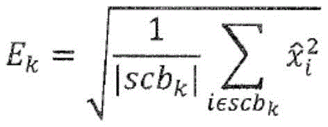
where k is igfStartSfb, 1+ igfStartSfb, 2+ igfStartSfb.
For quantization, calculation All values
 Is sent to the decoder.
Let us assume an encoderIt is decided to group num _ window _ group scale factor groups. The packet decomposition of the set 0,1,2, …,7, which is an index of 8 short windows, is denoted by w. w is alRepresents the ith subset of w, where l represents the index of the window group, and 0 ≦ l < num _ window _ group.
For short block calculations, the user-defined IGF start/stop frequencies are mapped to the appropriate scale factor bands. However, for simplicity, for short block representation: k ═ igfStartSfb, 1+ igfStartSfb, 2+ igfStartSfb.
IGF energy calculation uses grouping information to pair values Ek,lGrouping:

for quantization, calculation All values
 Is sent to the decoder.
The above-mentioned coding formula uses only real-valued MDCT coefficients And (5) carrying out operation. To obtain a more stable energy distribution in the IGF range, i.e. to reduce temporal amplitude fluctuations, alternative methods may be used to calculate the values
Is provided with A real-valued spectral representation of an MDCT transform of a windowed audio signal having a window length of 2N, and
 the real-valued MDST variations being the same part of the audio signalAnd (4) displaying the converted frequency spectrum. Can be accurately calculated or based on
 Estimating MDST spectral representation
 Representing a complex spectral representation of a windowed audio signal such that
 As a substantial part thereof,
 as its imaginary part. Alternatively, the encoder pair
 And
And TNS is used.
Now, the energy of the original signal in the IGF range can be measured using the following equation:

the real-valued energy and the complex-valued energy of the reconstructed band, i.e. in the reconstructed IGF range scbkTiles that should be used at the decoder side are calculated using the following equation:
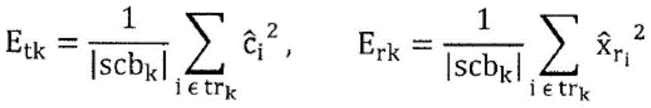
wherein, trkIs a set of index-dependent scbskAssociated source tile range of (1). In the above two formulas, the index set scb is replacedkCan use the group (defined subsequently herein) to reconstruct trkTo achieve a more accurate value EtAnd Er. Computing

If E istk> 0, otherwise fk=0。
Now make use of Calculation of EkSince E is calculated only in MDCT valueskMDCT values are compromised by the fact that they do not obey the pascal's theorem, and therefore they do not reflect the full energy information of the spectral values. Calculated according to the above
As noted earlier, for short blocks, assume that the encoder decides to group num _ window _ group scale factor groups. As mentioned above, wlRepresents the ith subset of w, where l represents the index of the window group, and 0 ≦ l < num _ window _ group.
Again, the above-summarized method for calculating E may be calculatedk,lAn alternative version of the more stable version of (c). Definition of
 Is a 2N-length MDCT transform windowed audio signal and
 is a length of 2N MDST transform windowed audio signal, calculated:

similarly, the calculation of the average,

and using a factor fk,lTo process the above-mentioned materials to obtain the invented product,
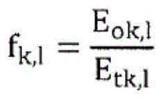
which is used to adjust the previously calculated Erk,l:

Calculated according to the above
A process that uses not only the energy of the reconstructed bands derived from the complex reconstructed bands or from MDCT values but also energy information from the source range provides an improved energy reconstruction.
In particular, the parameter calculator 1006 is configured to calculate the energy information on the reconstruction band using the information on the energy of the reconstruction band and additionally using the information on the energy of the source range to be used for reconstructing the reconstruction band.
Furthermore, the parameter calculator 1006 is configured to calculate energy information (E) on a reconstructed frequency band of the complex spectrum of the original signalok) To calculate further energy information (E) about the source range of the real-valued part of the complex spectrum of the original signal to be used for reconstructing the reconstructed bandrk) Wherein the parameter calculator is configured to use the energy information (E)ok) And additional energy information (E)rk) Energy information on the reconstructed frequency band is calculated.
Further, the parameter calculator 1006 is configured to: first energy information (E) for determining a reconstructed scale factor band for a complex spectrum of an original signalok) (ii) a For determining information about to be used for reconstructingThe scale factor band of (E) is the second energy information (E) of the source range of the complex spectrum of the original signal reconstructedtk) (ii) a Third energy information (E) for determining a source range of a real part of a complex spectrum of an original signal to be used for reconstructing a reconstructed scale factor bandrk) (ii) a For determining weighting information based on a relationship between at least two of the first energy information, the second energy information and the third energy information; and means for weighting one of the first energy information and the third energy information using the weighting information to obtain weighted energy information and using the weighted energy information as energy information on the reconstruction band.
Examples for the calculations are as follows, but in view of the general principles above, many other examples will occur to those skilled in the art:
A)
f_k=E_ok/E_tk;
E_k=sqrt(f_k*E_rk);
B)
f_k=E_tk/E_ok;
E_k=sqrt((1/f_k)*E_rk);
C)
f_k=E_rk/E_tk;
E_k=sqrt(f_k*E_ok)
D)
f_k=E_tk/E_rk;
E_k=sqrt((1/f_k)*E_ok)
all these examples acknowledge the following facts: although only real MDCT values are processed at the decoder side, the actual computation is a time-domain aliasing cancellation process that implicitly uses complex numbers due to the overlapping and adding. However, in particular, the determination 918 of the tile energy information of the further spectral portions 922, 923 of the reconstruction band 920 having frequency values different from the first spectral portion 921 of frequencies in the reconstruction band 920 depends on the real MDCT values. Therefore, the energy information sent to the decoder will typically be smaller than the energy information E on the reconstructed band of the complex spectrum of the original signalok. For example, for case C above, this means that the factor f _ k (weighting information) would be less than 1.
On the decoder side, if the IGF tool is signaled as on, the value sent Obtained from the bitstream and should be used for all k ═ igfStartSfb, 1+ igfStartSfb, 2+ igfStartSfb
 To dequantize.
The decoder dequantizes the transmitted MDCT values into And calculating the remaining residual energy:

wherein k is within the range defined above.
We mean that The set comprises scale factor bands scb that have been quantized to zero by the encoderkAll of the indices of (1).
The IGF acquisition subband method (not described here) is used to fill the spectral gaps due to the coarse quantization of MDCT spectral values at the encoder side by using the transmitted non-zero values of the MDCT. x would also include a value that replaces all previously cleared values. The tiling energy is calculated by:

wherein k is within the range defined above.
The energy lost in the reconstructed band is calculated by:
mEk:=|scbk|Ek 2-sEk
and the gain factor for the adjustment is obtained by:

wherein, g ═ min (g, 10).
The spectral envelope adjustment using this gain factor is: for all And k is within the range defined above,
xi:=g′xi
this reshapes the spectral envelope of x into the original spectral envelope The shape of (2).
For short window sequences, all the calculations outlined above remain the same in principle, but consider the grouping of scale factor bands. We denote the energy value of the dequantized packet obtained from the bitstream as Fk,l. Computing
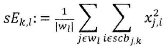
And
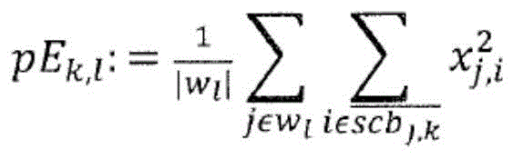
the index j describes the window index of the short block sequence.
Calculating mEk,l:=|scbk|Ek,l 2-sEk,l
And
wherein, g' ═ min (g, 10)
For all
Application xj,i:=g′xj,i。
For low bit rate applications, the value EkIs possible without losing too much precision. The method is applied only by long blocks:

where k is igfStartSfb, 2+ igfStartSfb, 4+ igfStartSfb, …, igfStartSfb.
Again, after quantization, all values Ek>>1Is sent to the decoder.
Fig. 9A shows an apparatus for decoding an encoded audio signal comprising an encoded representation of a first set of first spectral portions and an encoded representation of parametric data representing spectral energies for a second set of second spectral portions. The first set of first spectral portions is represented in fig. 9A at 901a and the encoded representation of the parametric data is represented at 901b of fig. 9A. The audio decoder 900 is provided for decoding the encoded representation 901a of the first set of first spectral portions to obtain a decoded first set of first spectral portions 904 and for decoding the encoded representation of the parametric data to obtain decoded parametric data 902 for a second set of second spectral portions representing individual energies of individual reconstruction bands, wherein the second spectral portions are located in the reconstruction bands. Furthermore, a frequency regenerator 906 is provided for reconstructing spectral values of a reconstruction band comprising the second spectral portion. The frequency regenerator 906 uses a first spectral portion of the first set of first spectral portions and individual energy information about a reconstruction band, wherein the reconstruction band comprises the first spectral portion and the second spectral portion. The frequency regenerator 906 comprises a calculator 912 for determining residual energy information comprising accumulated energy of the first spectral portion having frequencies in the reconstruction band. Furthermore, the frequency regenerator 906 comprises a calculator 918 for determining tile energy information for further spectral portions of the reconstruction band, while frequency values are different from the first spectral portion, wherein the frequency values have frequencies in the reconstruction band, wherein the further spectral portions are to be generated by frequency regeneration using a first spectral portion different from the first spectral portion in the reconstruction band.
The frequency regenerator 906 further comprises a calculator 914 for determining the missing energy in the reconstructed frequency band, and the calculator 914 operates using the individual energy of the reconstructed frequency band and the residual energy generated by block 912. Further, the frequency regenerator 906 comprises a spectral envelope adjuster 916 for adjusting the further spectral portion in the reconstructed frequency band based on the lost energy information and the tile energy information generated by block 918.
Referring to fig. 9C, fig. 9C shows a certain reconstruction band 920. The reconstructed frequency band comprises a first spectral portion in the reconstructed frequency band schematically shown at 921 as the first spectral portion 306 in fig. 3 a. Furthermore, the remaining spectral values in the reconstruction band 920 are to be generated using, for example, source regions from scale factor bands 1,2, 3 that are below the intelligent gap-filling start frequency of fig. 3 a. The frequency regenerator 906 is configured for generating original spectral values of the second spectral portions 922 and 923. Then, as shown in fig. 9c, a gain factor g is calculated to finally adjust the original spectral values in the frequency bands 922, 923 to obtain a reconstructed and adjusted second spectral portion in the reconstructed frequency band 920, which now has the same spectral resolution, i.e. the same line distance, as the first spectral portion 921. It is important to understand that the first spectral portion in the reconstructed frequency band shown at 921 in fig. 9C is decoded by the audio decoder 900 without being affected by the envelope adjustment performing block 916 of fig. 9 b. Alternatively, the first spectral portion in the reconstructed band represented at 921 is left as is, since it is output by the full bandwidth or full rate audio decoder 900 via line 904.
Subsequently, a specific example using real numbers will be discussed. The remaining residual energy calculated by block 912 is, for example, 5 energy units, and is the energy of the exemplarily represented 4 spectral lines in the first spectral portion 921.
Further, the energy value E3 of the reconstruction band corresponding to the scale factor band 6 of fig. 3B or fig. 3A is equal to 10 units. Importantly, the energy values include not only the energy of the spectral portions 922, 923, but also the total energy of the reconstructed band 920 calculated at the encoder side, i.e. before performing the spectral analysis using e.g. channel masking. Thus, 10 energy cells cover the first and second spectral portions in the reconstruction band. Then, assume that the energy of the source range data of blocks 922, 923 or the original target range data of blocks 922, 923 equals 8 energy units. Thus, 5 units of lost energy are calculated.
Based on the lost energy divided by the tile energy tEk, a gain factor of 0.79 is calculated. The original spectral lines of the second spectral portions 922, 923 are then multiplied by the calculated gain factors. Thus, only the spectral values of the second spectral portions 922, 923 are adjusted, while the spectral lines of the first spectral portion 921 are not affected by the envelope adjustment. After multiplication by the original spectral values of the second spectral portions 922, 923, a complete reconstruction band is calculated, which comprises the first spectral portion in the reconstruction band and comprises the spectral lines in the second spectral portions 922, 923 in the reconstruction band 920.
Preferably, the source range used to generate the raw spectral data in the frequency bands 922, 923 is lower than the IGF start frequency 309 with respect to frequency, while the reconstructed frequency band 920 is higher than the IGF start frequency 309.
Furthermore, the reconstruction band boundary preferably coincides with the scale factor band boundary. Thus, in one embodiment, the reconstruction band is sized with the corresponding scale factor band of the core audio decoder, or is sized such that: when applying energy matching, the energy values of the reconstructed frequency bands provide energies of an integer number of scale factor bands equal to or greater than 2. Thus, when assuming that energy accumulation is performed for scale factor band 4, scale factor band 5, and scale factor band 6, then the lower frequency boundary of reconstructed band 920 is equal to the lower boundary of scale factor band 4, while the upper frequency boundary of reconstructed band 920 coincides with the upper boundary of scale factor band 6.
Subsequently, fig. 9D is discussed to illustrate additional functionality of the decoder of fig. 9A. The audio decoder 900 receives dequantized spectral values corresponding to a first spectral portion of the first set of spectral portions and, additionally, provides the scale factors of the scale factor bands as shown in fig. 3B to the inverse scaling block 940. The inverse scaling block 940 provides all first sets of first spectral portions below the IGF start frequency 309 of fig. 3A and additionally provides first spectral portions above the IGF start frequency, i.e. the first spectral portions 304, 305, 306, 307 of fig. 3A, both located at the reconstruction band shown at 941 in fig. 9D. Furthermore, the first spectral portion in the source band used for frequency tile filling in the reconstruction band is provided to the envelope adjuster/calculator 942 and the block additionally receives energy information on the reconstruction band provided as parametric side information of the encoded audio signal as shown at 943 in fig. 9D. The envelope adjuster/calculator 942 then provides the functionality of fig. 9B and 9C, and finally outputs adjusted spectral values for the second spectral portion in the reconstructed frequency band. These adjusted spectral values 922, 923 of the second spectral portion in the reconstruction band and the first spectral portion 921 in the reconstruction band, represented by line 941 in fig. 9D, jointly represent a complete spectral representation of the reconstruction band.
Subsequently, referring to fig. 10A and 10B, fig. 10A and 10B are used to illustrate a preferred embodiment of an audio encoder for encoding an audio signal to provide or generate an encoded audio signal. The encoder comprises a time/spectrum converter 1002 which feeds a spectrum analyzer 1004, and the spectrum analyzer 1004 is connected to a parameter calculator 1006 on the one hand and to an audio encoder 1008 on the other hand. The audio encoder 1008 provides an encoded representation of the first set of first spectral portions and does not cover the second set of second spectral portions. On the other hand, the parameter calculator 1006 provides energy information of the reconstructed frequency band covering the first spectral portion and the second spectral portion. Further, the audio encoder 1008 is configured to generate a first encoded representation of a first set of first spectral portions having a first spectral resolution, wherein the audio encoder 1008 provides scale factors for all frequency bands of the spectral representation generated by the block 1002. In addition, as shown in fig. 3B, the encoder provides energy information for at least the reconstruction band that is located above the IGF starting frequency 309 as shown in fig. 3A with respect to frequency. Thus, for a reconstructed frequency band that preferably coincides with a scale factor band or with a group of scale factor bands, two values are given, i.e. the corresponding scale factor from the audio encoder 1008 and additionally the energy information output by the parameter calculator 1006.
Preferably, the audio encoder has scale factor bands with different frequency bandwidths, i.e. with different numbers of spectral values. Thus, the parameterization calculator comprises a normalizer 1012 for normalizing the energy of different bandwidths with respect to the bandwidth of a particular reconstruction band. To this end, the normalizer 1012 receives as input the energy in a frequency band and a number of spectral values in the frequency band, and the normalizer 1012 outputs the normalized energy per reconstruction/scale factor band.
In addition, the parameterizer 1006a of FIG. 10A includes an energy value calculator for receiving control information from the core or audio encoder 1008 as indicated by line 1007 in FIG. 10A. The control information may include information on long/short blocks used by the audio encoder and/or grouping information. Thus, while the information on long/short blocks and the grouping information on short windows are related to "time" grouping, the grouping information may also refer to spectral grouping, i.e., grouping two scale factor bands into a single reconstructed band. Thus, when only the spectral portions have been grouped, the energy value calculator 1014 outputs a single energy value covering the band of each of the first and second spectral portions.
Fig. 10D shows yet another embodiment for implementing spectrum grouping. To this end, block 1016 is configured for calculating energy values of two adjacent frequency bands. Then, in block 1018, the energy values of the two adjacent frequency bands are compared, and when the energy values are not significantly different or are different to a lesser extent than defined by, for example, a threshold, then a single (normalized) value for the two frequency bands is generated, as shown in block 1020. Block 1018 may be bypassed as shown by line 1019. Further, the generation of a single value for two or more frequency bands performed by block 1020 may be controlled by encoder bit rate controller 1024. Thus, when the bit rate is to be reduced, the encoding bit rate controller 1024 controls the block 1020 to generate a single normalized value for two or more frequency bands, even if the comparison in block 1018 is not allowed to group energy information values.
In case the audio encoder performs grouping of two or more short windows, the grouping is also applied for the energy information. When the core encoder performs the grouping of two or more short blocks, then only a single set of scale factors are calculated and transmitted for these two or more blocks. Then, on the decoder side, the audio decoder applies the same set of scale factors for the two grouped windows.
With regard to energy information calculation, spectral values in the reconstruction band are accumulated for two or more short windows. In other words, this means that spectral values in a certain reconstruction band of a short block and a subsequent short block are accumulated together, and for this reconstruction band covering both short blocks only a single energy information is transmitted. Then, at the decoder side, the envelope adjustment discussed with respect to fig. 9a to 9d is not performed separately for each short block, but is performed together for a group of grouped short windows.
Then, the respective normalization is applied again, so that even if any grouping in frequency or grouping in time has been performed, the normalization easily enables: for the energy value information calculation at the decoder side, only the energy value information and the amount of spectral lines in the reconstruction band or in a set of packet reconstruction bands must be known on the one hand.
In prior art BWE schemes, the reconstruction of HF spectral regions above a given so-called crossover frequency is typically based on spectral patching. Typically, the HF region includes a plurality of adjacent patches, and each of these patches is derived from a Bandpass (BP) region of the LF spectrum below a given crossover frequency. Such systems copy a set of adjacent subband coefficients in the LF spectrum into the target region within a filter bank representation of the signal. The boundaries of the selected groups are typically system dependent, not signal dependent. For some signal content, this static patching choice may result in unpleasant timbre and coloration of the reconstructed signal.
Other methods convert LF signals to HF by signal adaptive Single Sideband (SSB) modulation. Such methods have high computational complexity compared to [1], because they operate on time-domain samples at high sampling rates. Furthermore, the patching can become unstable, especially for non-tonal signals (e.g., non-speech voices), so that prior art signal adaptive patching can introduce impairments to the signal.
The method of the present invention is called Intelligent Gap Filling (IGF) and, according to its preferred configuration, it is applied to BWE systems based on time-frequency transformation, e.g. Modified Discrete Cosine Transform (MDCT). However, the teachings of the present invention are generally applicable, for example, approximately within a Quadrature Mirror Filterbank (QMF) based system.
An advantage of MDCT-based IGF configuration is seamless integration into MDCT-based audio encoders such as MPEG Advanced Audio Coding (AAC). Sharing the same transform for waveform audio coding and BWE significantly reduces the overall computational complexity of the audio codec.
Furthermore, the present invention provides a solution to the inherent stability problems found in prior art adaptive patching schemes.
The proposed system is based on the following observations: for some signals, unguided patching options can result in tonal variations and signal coloration. Repairing the noise-like STR by the tonal SSR may result in an unnatural sound if the signal is tonal in the Spectral Source Region (SSR) and is similar to noise in the Spectral Target Region (STR). The pitch of the signal may also vary, as the tonal structure of the signal may become misaligned or even destroyed by the repair process.
The proposed IGF system uses cross-correlation as a measure of similarity between a particular SSR and a particular STR to perform intelligent tile selection. The cross-correlation of two signals provides a measure of the similarity of those signals and, in addition, the lag of the maximum correlation and its sign. Thus, the correlation-based tile selection method can also be used to precisely adjust the spectral shift of the replicated spectrum to become as close as possible to the original spectral structure.
The basic contribution of the proposed system is the selection of an appropriate similarity measure and additionally the technique of stabilizing the tile selection process. The proposed technique provides an optimal balance between transient signal adaptation and simultaneous temporal stability. Providing temporal stability is especially important for signals with little similarity of SSR and STR and thus exhibiting low cross-correlation values or when employing ambiguous similarity measures. In this case, stabilization prevents the pseudo-random behavior of adaptive tile selection.
For example, one type of signal that generally poses a problem with prior art BWEs is characterized by different energy concentrations to arbitrary spectral regions, as shown in fig. 12A (left). Although there are methods available to adjust the spectral envelope and pitch of the reconstructed spectrum in the target region, for some signals these methods do not preserve the timbre well as shown in fig. 12A (right). In the example shown in fig. 12A, the target region of the original signal is above the so-called crossover frequency fxoverThe magnitude of the spectrum (fig. 12A, left) decreases approximately linearly. In contrast, in the reconstructed spectrum (fig. 12A, right side), there are different sets of valleys and peaks that are perceived as tonal artefacts.
An important step of the new method is to define a set of tiles in which subsequent similarity-based selections can be made. First, the tile boundaries between both the source and target regions must be defined in terms of each other. Thus, the IGF starting frequency f of the core encoderIGFstartWith the highest available frequency fIGFstopThe target area in between is divided into an arbitrary integer number of tiles of nTar, each of which has a respective predetermined size. Then, for each target tile tar [ idx _ tar]Generating a set of equally sized source tiles src idx _ src]. From this, the fundamental degrees of freedom of the IGF system were determined. The total number nSrc of source tiles is determined by the bandwidth of the source region,
bwsrc=(fIGFstart-fIGFmin)
wherein f isIGFminIs the lowest available frequency for tile selection, such that an integer number of nSrc for a source tile conforms to bwsrc. Of sheet materialThe minimum number is 0.
To further increase the freedom of selection and adjustment, the source tiles may be defined to overlap each other by an overlap factor between 0 and 1, where 0 denotes no overlap and 1 denotes 100% overlap. 100% overlap may imply that only one or no source tile is available.
Fig. 12B shows an example of tile boundaries for a set of tiles. In this case, all target tiles are associated with each source tile. In this example, the source tiles overlap by 50%.
For the target tile, the cross-correlation is calculated using various source tiles at the lags of the upper xcorr _ maxLag bins. For a given target tile idx _ tar and source tile idx _ src, xcorr _ val [ idx _ tar ] [ idx _ src ] gives the maximum value of absolute cross-correlation between tiles, whereas xcorr _ lag [ idx _ tar ] [ idx _ src ] gives the lag at which the maximum occurs and xcorr _ sign [ idx _ tar ] [ idx _ src ] gives the sign of cross-correlation at xcorr _ lag [ idx _ tar ] [ idx _ src ].
The parameter xcorr _ lag is used to control the proximity of the match between the source tile and the target tile. This parameter results in reduced artifacts and helps to better preserve the timbre and timbre of the signal.
In some scenarios, it may happen that the size of a particular target tile is larger than the size of the available source tiles. In this case, the available source tiles are repeated as often as necessary to completely fill the target tile. It is still possible to perform cross-correlation between a large target tile and a smaller source tile to obtain the best position of the source tile in the target tile from the cross-correlation lag xcorr _ lag and the sign xcorr _ sign.
The cross-correlation of the original spectral tile and the original signal may not be the most suitable similarity measure to be applied to an audio spectrum with a strong formant structure. Whitening of the spectrum removes coarse envelope information, emphasizing spectral fine structure, which is most beneficial for assessing tile similarity. Whitening also helps to easily envelope shape the STR at the decoder for regions processed by IGF. Thus, optionally, the tile and the source signal are whitened before the cross-correlation is calculated.
In other configurations, only the tile is whitened using a predetermined process. The "whitening" flag sent indicates to the decoder that the same predetermined whitening process should be applied to the tiles within the IGF.
To whiten the signal, a spectral envelope estimate is first computed. The MDCT spectrum is then divided by the spectral envelope. The spectral envelope estimate may be estimated based on MDCT spectra, MDCT spectral energies, MDCT-based complex power spectra, or power spectrum estimates. From now on, the signal on which the envelope is estimated will be referred to as the base signal.
The envelope computed as the base signal on the MDCT-based complex power spectrum or power spectrum estimate has the following advantages: there is no temporal fluctuation in the tonal components.
If the base signal is located in the energy domain, the MDCT spectrum must be divided by the square root of the envelope to properly whiten the signal.
There are different ways of computing the envelope:
transforming the base signal using a Discrete Cosine Transform (DCT), retaining only the lower DCT coefficients (setting the highest to zero), and then computing the inverse DCT
Computing the spectral envelope of a set of Linear Prediction Coefficients (LPCs) computed over a time-domain audio frame
Filtering the base signal with a low-pass filter
Preferably, the last method is selected. For applications requiring low computational complexity, some simplifications can be made to whitening of the MDCT spectrum: first, the envelope is calculated by means of a moving average. This requires only two processor cycles per MDCT bin. Then, to avoid division and square root computation, the spectral envelope is approximated to 2nWhere n is the integer logarithm of the envelope. In this domain, the square root operation simply becomes a shift operation, and furthermore a division operation by an envelope can be performed by another shift operation.
After calculating the correlation of each source tile with each target tile, for all nTar target tiles, the source tile with the highest correlation is selected to replace it. To best match the original spectral structure, the replicated spectrum is modulated by an integer number of transform bins using hysteresis in the correlation. In the case of odd lags, the tile is additionally modulated by multiplication by an alternating time series-1/1 to compensate for the frequency-reversed representation of each other band within the MDCT.
FIG. 12C illustrates an example of a correlation between a source tile and a target tile. In this example, the lag of the correlation is 5, so the source tile must be modulated 5 bins towards higher bins in the copy segment of the BWE algorithm. In addition, when the maximum correlation value is negative, the sign of the tile must be flipped, and the additional modulation as described above results in an odd lag.
Therefore, the entire number of side information transmitted from the encoder to the decoder may include the following data:
tileNum [ nTar ]: indexing of selected source tiles per target tile
tileSign [ nTar ]: symbol of target tile
tileNum [ nTar ]: hysteresis of correlation per target tile
Tile pruning and stabilization are important steps in IGF. An example is used to illustrate its needs and advantages, assuming a static tonal audio signal resembles, for example, a steady musical note. If the source tile is always selected from the same source region across multiple frames for a given target region, the logic indicates that minimal artifacts are introduced. Even if the signal is assumed to be static, this condition does not hold well in every frame since the similarity measure (e.g., correlation) of other equally similar source regions dominates the similarity result (e.g., cross-correlation). This causes tileNum nTar between adjacent frames to wobble between two or three very similar choices. This can be a source of objectionable musical noise such as artifacts.
To eliminate this type of artifact, a set of source tiles should be pruned so that the remaining members of the source set are maximally different. This is for a set of source tiles S ═ S1,s2,…snImplementation is as follows. Tiling S for any sourceiCorrelate it with all other source tiles, find SiAnd SjThe best correlation between them, and store it in the matrix Sx. Here, Sx[i][j]Comprising SiAnd SjThe maximum absolute correlation value between them. Adding the matrix S along the columnsxGiving a source tile SiThe sum of cross-correlations with all other source tiles T.
T[i]=Sx[i][1]+Sx[i][2]...+Sx[i][n]
Here, T represents a measure of how similar a source is to other source tiles. If T > the threshold for any source tile i, then the source tile i may be removed from the set of potential sources because it is highly correlated with other sources. The tile of the set of tiles having the smallest correlation that satisfies the condition in equation 1 is selected as the representative tile of the subset. In this way, it is ensured that the source tiles differ from each other to the greatest extent.
The tile trim method also includes a memory 1148 of trimmed tile groups used in the previous frame. If there are alternative candidate tiles for pruning, the tiles active in the previous frame are also retained in the next frame.
Tiles { s ] set in frame K1,s2...,s5Middle bedding S3、S4And S5Valid, in frame k +1, even tile S1、S3And S2Competition is to use S maximally correlated with other tiles3To trim, but S3Is preserved because it is a useful source tile in the previous frame, and thus it is beneficial to preserve it in the set of source tiles to enhance temporal continuity in tile selection. If represented as Tx[i][j]Is high, the method is preferably applied.
Additional methods for tile stabilization are: if none of the source tiles in the current frame k correlate well with the target tile, then the tile order from the previous frame k-1 is preserved. If represented as Tx[i][j]This may occur if the cross-correlation between source i and target j of (j) is low for all i, j.
For example, if Tx[i][j]<0.6
The tentative threshold now used, then for all nTar of this frame k,
tileNum[nTar]k=tileNum[nTar]k-1
both of the above techniques greatly reduce the artifacts that occur due to rapidly changing group tile numbers across multiple frames. Another additional advantage of the tile trimming and stabilizing is that: no additional information needs to be sent to the decoder nor does it need to change the decoder architecture. The proposed tile pruning is an elegant way of reducing potential musical noise, such as artifacts or excessive noise, in spectral regions.
Fig. 11A shows an audio decoder for decoding an encoded audio signal. The audio decoder comprises an audio (core) decoder 1102 for generating a first decoded representation of a first set of first spectral portions, the decoded representation having a first spectral resolution.
Furthermore, the audio decoder comprises a parametric decoder 1104 for generating a second decoded representation of a second set of second spectral portions, the second decoded representation having a second spectral resolution, the second spectral resolution being smaller than the first spectral resolution. Furthermore, a frequency regenerator 1106 is provided for receiving the decoded first spectral portion as a first input 1101 and parametric information comprising for each target frequency or target reconstruction band source range information as a second input at 1103. Then, the frequency regenerator 1106 applies frequency regeneration by using spectral values from the source range identified by the matching information to generate spectral data of the target range. Then, the outputs of the first spectral portion 1101 and the frequency regenerator 1107 are both input to a spectrotime converter 1108 to finally generate a decoded audio signal.
Preferably, the audio decoder 1102 is a spectral domain audio decoder, although the audio decoder may also be implemented as any other audio decoder, such as a temporal or parametric audio decoder.
As represented at fig. 11B, the frequency regenerator 1106 may include the following functionality: a block 1120 for an odd hysteresis source range selector tile modulator, a whitening filter 1122 when a whitening flag 1125 is provided is shown, and additionally includes the spectral envelope adjustment function shown in block 1128 implemented using the raw spectral data generated by either block 1120 or block 1122 or the cooperation of the two blocks. In any event, the frequency regenerator 1106 may include a switch 1124 responsive to the received whitening flag 1125. When the whitening flag is set, the output of the source range selector/tile modulator for odd lags is input to the whitening filter 1122. However, then, the whitening flag 1125 is not set for a certain reconstructed band, then the bypass line 1126 is activated so that the output of the block 1120 is provided to the spectral envelope adjustment block 1128 without any whitening.
There may be more than one level of whitening signaled in the bitstream (1123), and these levels may be signaled per tile. In case there are three levels signaled per tile, they should be coded in the following way:
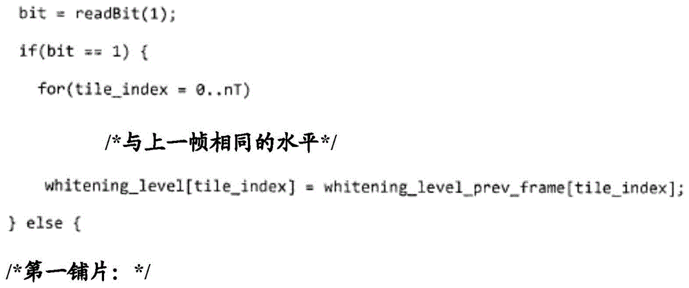


MID _ WHITENING and STRONG _ WHITENING refer to different whitening filters (1122), and the whitening filters (1122) may differ in the manner in which the envelope is calculated (as previously described).
When only a coarse spectral tile selection scheme is applied, the decoder-side frequency regenerator may be controlled by the source range ID 1121. However, when a fine-tuned spectral tile selection scheme is applied, then a source range lag 1119 is additionally provided. Further, assuming that the correlation calculation provides a negative result, then, in addition, the sign of the correlation may be applied to block 1120, such that the page data spectral lines are each multiplied by "-1" to account for the negative sign.
Thus, as discussed in fig. 11A, 11B, the present invention believes that: due to the fact that the best matching source range of a certain destination or target range is calculated at the encoder side and applied at the decoder side, the best audio quality is obtained.
Fig. 11C is an audio encoder for encoding an audio signal, comprising a temporal-spectral converter 1130, a subsequently connected spectral analyzer 1132 and additionally a parameter calculator 1134 and a core encoder 1136. The core encoder 1136 outputs the encoded source range and the parameter calculator 1134 outputs the matching information for the target range.
The encoded source range is transmitted to the decoder along with matching information about the target range, so that the decoder shown in fig. 11A can perform frequency regeneration.
The parameter calculator 1134 is configured for calculating a similarity between the first spectral portion and the second spectral portion and for determining a matching first spectral portion for the second spectral portion that matches the second spectral portion based on the calculated similarity. Preferably, the matching results of the different source ranges and target ranges as shown in fig. 12A, 12B determine that the selected matching pair comprises the second spectral portion, and the parameter calculator is configured to provide this matching information identifying the matching pair into the encoded audio signal. Preferably, the parameter calculator 1134 is configured to use a predetermined target region in the second set of second spectral portions or a predetermined source region in the first set of first spectral portions, as shown for example in fig. 12B. Preferably, the predetermined target regions are non-overlapping, or the predetermined source regions are overlapping. When the predetermined source region is a subset of the first set of first spectral portions below the gap-fill start frequency 309 of fig. 3A, and preferably, the predetermined target region covering the lower spectral region coincides with its lower frequency boundary having the gap-fill start frequency, such that any target range is above the gap-fill start frequency and the source range is below the gap-fill start frequency.
As discussed, fine granularity is achieved by comparing the target region to the source region without any lag between the target region and the source region, but with a particular lag for the same target region. These lags are applied in the cross-correlation calculator 1140 of fig. 11D, and the matching pair selection is ultimately performed by the tile selector 1144.
Further, source range and/or target range whitening, shown at block 1142, is preferably performed. This block 1142 then provides a whitening flag to the bitstream, which is used to control the decoder-side switch 1124 of fig. 11B. Furthermore, if the cross-correlation calculator 1140 provides a negative result, the negative result is also signaled to the decoder. Thus, in the preferred embodiment, the tile selector outputs the source range ID, lag, sign of the target range, and block 1142 additionally provides a whitening flag.
Further, the parameter calculator 1134 is configured to perform the source tile pruning 1146 by reducing the number of potential source scopes in that: a source patch is removed from a set of potential source tiles based on a similarity threshold. Thus, when the similarity between two source tiles is greater than or equal to the similarity threshold, then one of the two source tiles is removed from the set of potential sources and the removed source tile is no longer used for further processing, and in particular, may not be selected by tile selector 1144 or used for cross-correlation calculations between different source and target ranges performed in block 1140.
Different implementations have been described with reference to different figures. Fig. 1A to 5C relate to a full rate or full bandwidth encoder/decoder scheme. Fig. 6A to 7E relate to an encoder/decoder scheme using TNS or TTS processing. Fig. 8A to 8E relate to an encoder/decoder scheme with specific binaural processing. Fig. 9A to 10D relate to specific energy information calculation and application, and fig. 11A to 12C relate to a specific manner of tile selection.
All these different aspects may be applications of the invention independently of each other, but may alternatively be applied together substantially as shown in fig. 2A and 2B. However, the specific binaural processing may also be applied to the encoder/decoder scheme as shown in fig. 13, and the same is true for the TNS/TTS processing, the envelope energy information calculation and application in the reconstructed frequency band, or the corresponding application at the adaptive source range identification and decoder side. On the other hand, the full rate aspect applies with or without TNS/TTS processing, with or without binaural processing, with or without adaptive source range identification or other types of energy computation using spectral envelope representation. Thus, it is clear that features of one of these various aspects may also be applied in other aspects.
Although some aspects are described in the context of a device for encoding or decoding, it is clear that these aspects also give a description of a corresponding method, wherein one block or means corresponds to a method step or a feature of a method step. Similarly, aspects described in the context of method steps also give a description of the respective block or item or a feature of the respective apparatus. Some or all of the method steps may be performed by (or using) a hardware device, such as a microprocessor, a programmable computer, or an electronic circuit. In some embodiments, some or more of the most important method steps may be performed by such a device.
Embodiments of the present invention may be implemented in hardware or software, depending on certain implementation requirements. Implementations may be implemented using a non-transitory storage medium, e.g., a digital storage medium, such as a floppy disk, a Hard Disk Drive (HDD), a DVD, a blu-ray, a CD, a ROM, a PROM, and EPROM, an EEPROM or a flash memory having electronically readable control signals stored thereon, which cooperate (or are capable of cooperating) with a programmable computer system such that the respective method is performed. Accordingly, the digital storage medium may be computer-readable.
Some embodiments according to the invention comprise a data carrier having electronically readable control signals capable of cooperating with a programmable computer system such that one of the methods described herein is performed.
In general, embodiments of the invention can be implemented as a computer program product having a program code for performing one of the methods when the computer program product runs on a computer. The program code may be stored, for example, on a machine-readable carrier.
Other embodiments include a computer program stored on a machine-readable carrier for performing one of the methods described herein.
In other words, an embodiment of the method of the invention is thus a computer program having a program code for performing one of the methods described herein, when the computer program runs on a computer.
Thus, a further embodiment of the method of the present invention is a data carrier (or digital storage medium or computer readable medium) comprising a computer program stored thereon for performing one of the methods described herein. The data carrier, the digital storage medium or the recording medium is typically tangible and/or non-transitory.
Thus, another embodiment of the method of the present invention is a data stream or signal sequence representing a computer program for performing one of the methods described herein. The data stream or signal sequence may be arranged to be transmitted, for example, via a data communication connection, for example, via the internet.
Yet another embodiment comprises a processing device, such as a computer or programmable logic device, configured or adapted to perform one of the methods described herein.
Yet another embodiment comprises a computer having installed thereon a computer program for performing one of the methods described herein.
Yet another embodiment according to the present invention comprises an apparatus or system configured to transmit (e.g., electronically or optically) a computer program for performing one of the methods described herein to a receiver. The receiver may be, for example, a computer, a mobile device, a storage device, etc. The device or system may comprise, for example, a file server for transmitting the computer program to the receiver.
In some implementations, a programmable logic device (e.g., a field programmable gate array) may be used to perform some or all of the functions of the methods described herein. In some embodiments, a field programmable gate array may cooperate with a microprocessor to perform one of the methods described herein. Generally, the methods are preferably performed by any hardware device.
The above-described embodiments are merely illustrative of the principles of the present invention. It should be understood that modifications and variations of the arrangements and details described herein will be apparent to those skilled in the art. Therefore, no limitations are intended to the details given with the aid of the description of embodiments herein.
List of cited documents
[1]Dietz、L.Liljeryd、K. Kunz, "Spectral Band Replication, anovel approach in audio coding", 112 th AES (Audio engineering society) conference, Munich, 5 months 2002
[2] Ferreira, D.Sinha, "Accurate Spectral Replacement", conference on Audio engineering Association, Barcelona, Spain, 2005
[3] Sinha, a. ferreira1 and e.harinarayan, "ANovel Integrated AudioBandwidth Extension Toolkit (ABET)", conference of audio engineering association, paris, france, 2006
[4] R.anadana, e.harinarayanan, a.ferreira and d.sinha, "New Results in LowBit Rate Speech Coding and Bandwidth Extension", conference on audio engineering society, san francisco, usa, 2006
[5]T. Bartkkowiak, "Audio band width extension by frequency classification of sinusoidal partials", conference of Audio engineering Association, san Francisco, USA, 2008
[6] Herre, D.Schulz, extension the MPEG-4AAC Codec by Perceptial NoiseSubstistion, 104 th AES conference, Amsterdam, 1998, preprint 4720
[7] M.Neuendorf, M.Multrus, N.Rettelbach et al, MPEG Unified Speech and audiocoding-The ISO/MPEG Standard for High-Efficiency Audio Coding of AllContent Types, AES (Audio engineering Association) conference 132, Budapest, Hungary, 4 months 2012
[8] McAula, Robert J., Quatieri, Thomas F, "Speech Analysis/Synthesis based on a Sinosomatic reproduction", IEEE transaction on Acoustic, Speech and Signal processing, Vol.34 (4), 8/1986
[9] Smith, J.O., Serra, X., "PARSHL: An analysis/synthesis program for non-musical bases based on a national music presentation", meeting minutes of International computer music conference, 1987
[10] Purnhagen, h.; meine, Nikolaus, "HILN-the MPEG-4parametric audio tools", Circuit and System, 2000 ISCAS conference record, Geneva, 2000IEEE International conference, Vol.3, pp.201, 204, Vol.3, 2000IEEE International conference, Vol.3
[11] International Standard ISO/IEC 13818-3, "genetic Coding of Moving Pictures and Audio: Audio", Geneva, 1998
[12] M.bosi, k.brandenburg, s.quekenburg, l.fielder, k.akagliri, h.fuchs, m.dietz, j.herre, g.davidson, Oikawa, "MPEG-2 Advanced Audio Coding", 101 th AES conference, los angeles, 1996 year
[13] Herre, "Temporal Noise Shaping, quantification and Coding method Temporal Audio Coding: atomic interaction", 17 th AES (Audio engineering society) International conference on high quality Audio Coding, 8 months 1999
[14] Herre, "Temporal Noise Shaping, quantification and Coding method Temporal Audio Coding: atomic interaction", 17 th AES (Audio engineering society) International conference on high quality Audio Coding, 8 months 1999
[15] International Standard ISO/IEC 23001-3:2010, Unified speed and audio coding Audio, Geneva, 2010
[16] International Standard ISO/IEC 14496-3:2005, Information technology-Coding of Audio-visual objects-Part 3: Audio, Geneva, 2005
[17] Ekstrand, "Bandwidth Extension of Audio Signals by Spectral Bandwidth", conference record on MPCA 1 st IEEE Binlugu economic Association seminar, Lefen, 2002, 11 months
[18] Nagel, s.disch, s.wide, Acontinuous modulated single side band and width extension, ICASSP international conference on acoustics, speech and signal processing, dallas, texas (usa), 4 months 2010
Inventive concept
The invention provides the following inventive concepts:
1. an apparatus for decoding an encoded signal, comprising:
an audio decoder (1102), the audio decoder (1102) being configured to decode an encoded representation of a first set of first spectral portions to obtain a decoded first set of first spectral portions (1101);
a parametric decoder (1104) for decoding an encoded parametric representation of a second set of second spectral portions to obtain a decoded representation (1103) of the parametric representation, wherein the parametric information comprises for each target frequency tile a source region identity as matching information; and
a frequency regenerator (1106), the frequency regenerator (1106) to regenerate a target frequency tile using a source region from the first set of first spectral portions (1101) identified by the matching information.
2. According to the apparatus of the inventive concept 1,
wherein the audio decoder (1102) is a spectral domain audio decoder, and
wherein the apparatus further comprises a spectro-temporal converter (1108) for converting a spectral representation of the first spectral portion and the reconstructed second spectral portion into a temporal representation.
3. According to the device of one of the inventive concepts 1 or 2,
wherein the frequency regenerator (1106) comprises a controllable whitening filter (1122, 1123),
wherein the parametric information (1103) comprises whitening information (1123), and
wherein the frequency regenerator (1106) is configured for: when the whitening information of a source region selected according to the matching information indicates that the source region is to be whitened, the whitening filter (1122) is applied to the source region before spectral envelope adjustment (1128) is performed.
4. According to the apparatus of the inventive concept 3,
wherein the whitening information comprises, for a tile or a set of tiles, whitening level information indicating a level of whitening to be applied to a source frequency tile when regenerating the target frequency tile, and
wherein the frequency regenerator (1106) is configured for: applying a whitening filter selected from a set of different whitening filters in response to the whitening information.
5. According to the device of one of the preceding inventive concepts,
wherein the frequency regenerator (1106) comprises a source region modifier,
wherein the parameterization information comprises symbol information in addition to the source area identification, and
wherein the source area modifier is configured to: applying an operation of obtaining a phase shift of source region spectral values from the symbol information.
6. According to the device of one of the preceding inventive concepts,
wherein the frequency regenerator (1106) comprises a tile modulator (1120),
wherein the parameterization information (1103) comprises a dependency hysteresis in addition to the source region identification (1121), and
wherein the tile modulator is configured to: applying tile modulation in accordance with the correlation lag associated with the source region identification (1121).
7. According to the device of one of the preceding inventive concepts,
wherein the frequency regenerator (1106) comprises a tile modulator (1120),
wherein the parameterization information (1103) comprises a dependency hysteresis in addition to the source region identification (1121), and
wherein the tile modulator (1120) is configured for: when the correlation lag is odd, tile modulation using an alternating time sequence-1/1 is applied.
8. An apparatus for encoding an audio signal, comprising:
a time-to-spectrum converter (1130), the time-to-spectrum converter (1130) for converting an audio signal into a spectral representation;
a spectrum analyzer for analyzing the spectral representation to determine a first set of first spectral portions to be encoded at a first spectral resolution and a second set of second spectral portions to be encoded at a second spectral resolution, wherein the second spectral resolution is lower than the first spectral resolution;
a parameter calculator (1134), the parameter calculator (1134) being configured to calculate a similarity between a predetermined source region and a target region, the source region comprising a spectral portion and the target region comprising a second spectral portion,
wherein the parameter calculator (1134) is configured for: comparing matching results of different pairs of the first and second portions of spectrum to determine a selected matching pair and providing matching information identifying the matching pair; and
a core encoder (1136), the core encoder (1136) being configured to encode the first set of first spectral portions, wherein the first set of first spectral portions includes the predetermined source region and spectral portions different from the predetermined source region.
9. According to the apparatus of the inventive concept 8,
wherein the parameter calculator (1134) is configured for: using a predetermined target region in the second set of second spectral portions or a predetermined source region in the first set of first spectral portions.
10. According to the apparatus of the inventive concept 8,
wherein the parameter calculator (1134) is configured such that: the predetermined target area is non-overlapping, or the predetermined source area is overlapping, or wherein the predetermined source area is a subset of the first set of first spectral portions below a gap-fill start frequency (309), or wherein the predetermined target area covers a lowest spectral area coinciding with the gap-fill start frequency (309).
11. The device according to one of the inventive concepts 8, 9 or 10,
wherein the parameter calculator (1134) is configured for: comparing pairs of destination and source regions and pairs of the destination and same source regions, wherein the same source region is shifted by a correlation lag to provide information about the correlation lag of the selected pair as additional matching information.
12. The audio encoder according to any of the inventive concepts 8 to 11,
wherein the parameter calculator (1134) is configured for: performing a correlation process to obtain a matching result of a pair of the first and second spectral portions, the matching result having a negative sign, an
Wherein the parameter calculator (1134) is configured to: providing information about the negative sign as additional matching information.
13. The audio encoder according to any of the inventive concepts 8 to 12,
wherein the parameter calculator (1134) is configured to: determine an integer number of target tiles and determine a plurality of equally sized source tiles for each target tile, or
Wherein the parameter calculator is configured to: when a target tile is larger than a source tile, the source tile is copied into the target tile multiple times until the target tile is filled with multiple copies of the source tile.
14. The audio encoder according to any of the inventive concepts 8 to 13,
wherein the parameter calculator (1134) is configured for: spectrally whitening (1142) the first or second spectral portion of the pair before performing correlation processing to obtain a match identification.
15. According to the device of one of the inventive concepts 8 to 14,
wherein the parameter calculator (1134) is configured for: calculating a spectral envelope of the first or second spectral portion using at least one of:
transforming the spectrum using a Discrete Cosine Transform (DCT), preserving lower frequency DCT coefficients by setting higher DCT coefficients to zero, and computing an inverse DCT;
calculating a spectral envelope of a set of linear prediction coefficients calculated over a time domain audio frame; or
The modified discrete cosine transform (power) spectrum is filtered using a low pass filter.
16. The apparatus according to one of the inventive concepts 8 to 15, further comprising: a source tile pruning operation (1146) and a memory (1148) for storing source tile information for an earlier frame prior to the current frame.
17. According to the device of one of the inventive concepts 8 to 16,
wherein the source pruning operation (1146) includes: the plurality of source tiles are analyzed for similarity with respect to the plurality of source tiles, and source tiles having a similarity greater than a predetermined threshold with respect to different source tiles are removed from the set of potential tiles used for the cross-correlation calculation (1140).
18. According to the device of one of the inventive concepts 12 to 17,
wherein the parameter calculator is configured to: when none of the source regions in a current frame is associated with a target region of the current frame, better than a predetermined threshold relative to a previous frame, retaining a set of matching information for each target region from the previous frame.
19. A method of decoding an encoded signal, comprising:
decoding (1102) the encoded representation of the first set of first spectral portions to obtain a decoded first set of first spectral portions (1101),
decoding (1104) the encoded parametric representation of the second set of second spectral portions to obtain a decoded representation (1103) of the parametric representation, wherein the parametric information comprises for each target frequency tile a source region identity as matching information; and
regenerating (1106) a target frequency tile using a source region from the first set of first spectral portions (1101) identified by the matching information.
20. A method of encoding an audio signal, comprising:
converting (1130) the audio signal into a spectral representation;
analyzing (1132) the spectral representation to determine a first set of first spectral portions to be encoded at a first spectral resolution and a second set of second spectral portions to be encoded at a second spectral resolution, wherein the second spectral resolution is lower than the first spectral resolution;
calculating (1134) a similarity between a predetermined source region and a target region, the source region comprising a spectral portion and the target region comprising a second spectral portion,
wherein the calculating (1134) comprises: comparing matching results of different pairs of the first and second portions of spectrum to determine a selected matching pair, and providing matching information identifying the matching pair; and
encoding (1136) the first set of first spectral portions, wherein the first set of first spectral portions includes the predetermined source region and spectral portions different from the predetermined source region.
21. A computer program for performing any one of the methods according to the inventive concept 19 or 20 when run on a computer or processor.
Claims (10)
1. An apparatus for decoding an encoded signal, comprising:
an audio decoder (1102), the audio decoder (1102) being configured to decode an encoded representation of a first set of first spectral portions to obtain a decoded first set of first spectral portions (1101);
a parametric decoder (1104) for decoding an encoded parametric representation of a second set of second spectral portions to obtain a decoded representation (1103) of the parametric representation, wherein the parametric information comprises for each target frequency tile a source region identity as matching information; and
a frequency regenerator (1106), the frequency regenerator (1106) to regenerate a target frequency tile using a source region from the first set of first spectral portions (1101) identified by the matching information.
2. The apparatus as set forth in claim 1, wherein,
wherein the audio decoder (1102) is a spectral domain audio decoder, and
wherein the apparatus further comprises a spectro-temporal converter (1108) for converting a spectral representation of the first spectral portion and the reconstructed second spectral portion into a temporal representation.
3. The apparatus as set forth in claim 1, wherein,
wherein the frequency regenerator (1106) comprises a controllable whitening filter (1122, 1123),
wherein the parametric information (1103) comprises whitening information (1123), and
wherein the frequency regenerator (1106) is configured for: when the whitening information of a source region selected according to the matching information indicates that the source region is to be whitened, the whitening filter (1122) is applied to the source region before spectral envelope adjustment (1128) is performed.
4. The apparatus as set forth in claim 3, wherein,
wherein the whitening information comprises, for a tile or a set of tiles, whitening level information indicating a level of whitening to be applied to a source frequency tile when regenerating the target frequency tile, and
wherein the frequency regenerator (1106) is configured for: applying a whitening filter selected from a set of different whitening filters in response to the whitening information.
5. The apparatus as set forth in claim 1, wherein,
wherein the frequency regenerator (1106) comprises a source region modifier,
wherein the parameterization information comprises symbol information in addition to the source area identification, and
wherein the source area modifier is configured to: applying an operation of obtaining a phase shift of source region spectral values from the symbol information.
6. The apparatus as set forth in claim 1, wherein,
wherein the frequency regenerator (1106) comprises a tile modulator (1120),
wherein the parameterization information (1103) comprises a dependency hysteresis in addition to the source region identification (1121), and
wherein the tile modulator is configured to: applying tile modulation in accordance with the correlation lag associated with the source region identification (1121).
7. The apparatus as set forth in claim 1, wherein,
wherein the frequency regenerator (1106) comprises a tile modulator (1120),
wherein the parameterization information (1103) comprises a dependency hysteresis in addition to the source region identification (1121), and
wherein the tile modulator (1120) is configured for: when the correlation lag is odd, tile modulation using an alternating time sequence-1/1 is applied.
8. An apparatus for encoding an audio signal, comprising:
a time-to-spectrum converter (1130), the time-to-spectrum converter (1130) for converting an audio signal into a spectral representation;
a spectrum analyzer for analyzing the spectral representation to determine a first set of first spectral portions to be encoded at a first spectral resolution and a second set of second spectral portions to be encoded at a second spectral resolution, wherein the second spectral resolution is lower than the first spectral resolution;
a parameter calculator (1134), the parameter calculator (1134) being configured to calculate a similarity between a predetermined source region and a target region, the source region comprising a spectral portion and the target region comprising a second spectral portion,
wherein the parameter calculator (1134) is configured for: comparing matching results of different pairs of the first and second portions of spectrum to determine a selected matching pair and providing matching information identifying the matching pair; and
a core encoder (1136), the core encoder (1136) being configured to encode the first set of first spectral portions, wherein the first set of first spectral portions includes the predetermined source region and spectral portions different from the predetermined source region.
9. The apparatus as set forth in claim 8, wherein,
wherein the parameter calculator (1134) is configured for: using a predetermined target region in the second set of second spectral portions or a predetermined source region in the first set of first spectral portions.
10. The apparatus as set forth in claim 8, wherein,
wherein the parameter calculator (1134) is configured such that: the predetermined target area is non-overlapping, or the predetermined source area is overlapping, or wherein the predetermined source area is a subset of the first set of first spectral portions below a gap-fill start frequency (309), or wherein the predetermined target area covers a lowest spectral area coinciding with the gap-fill start frequency (309).
Priority Applications (1)
| Application Number | Priority Date | Filing Date | Title |
|---|---|---|---|
| CN202010010552.6A CN111179963B (en) | 2013-07-22 | 2014-07-15 | Audio signal decoding and encoding device and method using adaptive spectrum tile selection |
Applications Claiming Priority (13)
| Application Number | Priority Date | Filing Date | Title |
|---|---|---|---|
| EP13177346 | 2013-07-22 | ||
| EP13177353 | 2013-07-22 | ||
| EP13177350 | 2013-07-22 | ||
| EP13177353.3 | 2013-07-22 | ||
| EP13177348.3 | 2013-07-22 | ||
| EP13177346.7 | 2013-07-22 | ||
| EP13177348 | 2013-07-22 | ||
| EP13177350.9 | 2013-07-22 | ||
| EP13189368.7A EP2830064A1 (en) | 2013-07-22 | 2013-10-18 | Apparatus and method for decoding and encoding an audio signal using adaptive spectral tile selection |
| EP13189368.7 | 2013-10-18 | ||
| CN202010010552.6A CN111179963B (en) | 2013-07-22 | 2014-07-15 | Audio signal decoding and encoding device and method using adaptive spectrum tile selection |
| CN201480041566.7A CN105580075B (en) | 2013-07-22 | 2014-07-15 | Audio signal decoding and encoding apparatus and method with adaptive spectral tile selection |
| PCT/EP2014/065116 WO2015010952A1 (en) | 2013-07-22 | 2014-07-15 | Apparatus and method for decoding and encoding an audio signal using adaptive spectral tile selection |
Related Parent Applications (1)
| Application Number | Title | Priority Date | Filing Date |
|---|---|---|---|
| CN201480041566.7A Division CN105580075B (en) | 2013-07-22 | 2014-07-15 | Audio signal decoding and encoding apparatus and method with adaptive spectral tile selection |
Publications (2)
| Publication Number | Publication Date |
|---|---|
| CN111179963A true CN111179963A (en) | 2020-05-19 |
| CN111179963B CN111179963B (en) | 2024-11-22 |
Family
ID=49385156
Family Applications (12)
| Application Number | Title | Priority Date | Filing Date |
|---|---|---|---|
| CN202010010552.6A Active CN111179963B (en) | 2013-07-22 | 2014-07-15 | Audio signal decoding and encoding device and method using adaptive spectrum tile selection |
| CN201910412164.8A Active CN110310659B (en) | 2013-07-22 | 2014-07-15 | Apparatus and method for decoding or encoding audio signal using reconstructed band energy information value |
| CN201480002625.XA Active CN104769671B (en) | 2013-07-22 | 2014-07-15 | Apparatus and method for encoding and decoding encoded audio signals using temporal noise/patch shaping |
| CN201910689687.7A Active CN110660410B (en) | 2013-07-22 | 2014-07-15 | Audio encoder, audio decoder and related methods |
| CN201480041218.XA Active CN105556603B (en) | 2013-07-22 | 2014-07-15 | Apparatus and method for decoding an encoded audio signal using a crossover filter around transition frequencies |
| CN201480041246.1A Active CN105453175B (en) | 2013-07-22 | 2014-07-15 | Apparatus, method, and computer-readable medium for decoding an encoded audio signal |
| CN201480041267.3A Active CN105518776B (en) | 2013-07-22 | 2014-07-15 | Apparatus and method for decoding or encoding audio signals with reconstructed band energy information values |
| CN201480041566.7A Active CN105580075B (en) | 2013-07-22 | 2014-07-15 | Audio signal decoding and encoding apparatus and method with adaptive spectral tile selection |
| CN201911415693.XA Active CN111554310B (en) | 2013-07-22 | 2014-07-15 | Apparatus and method for encoding or decoding an audio signal using spectral domain intelligent gap filling |
| CN201480041248.0A Active CN105518777B (en) | 2013-07-22 | 2014-07-15 | Apparatus and method for encoding or decoding an audio signal with intelligent gap filling in the spectral domain |
| CN202011075098.9A Active CN112466312B (en) | 2013-07-22 | 2014-07-15 | Device, method and computer program for decoding a coded audio signal |
| CN201480041226.4A Active CN105453176B (en) | 2013-07-22 | 2014-07-15 | Audio encoder, audio decoder and related method using binaural processing in the framework of intelligent gap filling |
Family Applications After (11)
| Application Number | Title | Priority Date | Filing Date |
|---|---|---|---|
| CN201910412164.8A Active CN110310659B (en) | 2013-07-22 | 2014-07-15 | Apparatus and method for decoding or encoding audio signal using reconstructed band energy information value |
| CN201480002625.XA Active CN104769671B (en) | 2013-07-22 | 2014-07-15 | Apparatus and method for encoding and decoding encoded audio signals using temporal noise/patch shaping |
| CN201910689687.7A Active CN110660410B (en) | 2013-07-22 | 2014-07-15 | Audio encoder, audio decoder and related methods |
| CN201480041218.XA Active CN105556603B (en) | 2013-07-22 | 2014-07-15 | Apparatus and method for decoding an encoded audio signal using a crossover filter around transition frequencies |
| CN201480041246.1A Active CN105453175B (en) | 2013-07-22 | 2014-07-15 | Apparatus, method, and computer-readable medium for decoding an encoded audio signal |
| CN201480041267.3A Active CN105518776B (en) | 2013-07-22 | 2014-07-15 | Apparatus and method for decoding or encoding audio signals with reconstructed band energy information values |
| CN201480041566.7A Active CN105580075B (en) | 2013-07-22 | 2014-07-15 | Audio signal decoding and encoding apparatus and method with adaptive spectral tile selection |
| CN201911415693.XA Active CN111554310B (en) | 2013-07-22 | 2014-07-15 | Apparatus and method for encoding or decoding an audio signal using spectral domain intelligent gap filling |
| CN201480041248.0A Active CN105518777B (en) | 2013-07-22 | 2014-07-15 | Apparatus and method for encoding or decoding an audio signal with intelligent gap filling in the spectral domain |
| CN202011075098.9A Active CN112466312B (en) | 2013-07-22 | 2014-07-15 | Device, method and computer program for decoding a coded audio signal |
| CN201480041226.4A Active CN105453176B (en) | 2013-07-22 | 2014-07-15 | Audio encoder, audio decoder and related method using binaural processing in the framework of intelligent gap filling |
Country Status (19)
| Country | Link |
|---|---|
| US (24) | US10332539B2 (en) |
| EP (20) | EP2830064A1 (en) |
| JP (12) | JP6144773B2 (en) |
| KR (7) | KR101681253B1 (en) |
| CN (12) | CN111179963B (en) |
| AU (7) | AU2014295297B2 (en) |
| BR (12) | BR122022010958B1 (en) |
| CA (8) | CA2918701C (en) |
| ES (10) | ES2908624T3 (en) |
| MX (7) | MX354002B (en) |
| MY (6) | MY182831A (en) |
| PL (8) | PL3025340T3 (en) |
| PT (7) | PT3407350T (en) |
| RU (7) | RU2649940C2 (en) |
| SG (7) | SG11201600422SA (en) |
| TR (1) | TR201816157T4 (en) |
| TW (7) | TWI555009B (en) |
| WO (7) | WO2015010952A1 (en) |
| ZA (5) | ZA201502262B (en) |
Families Citing this family (110)
| Publication number | Priority date | Publication date | Assignee | Title |
|---|---|---|---|---|
| JPH0726265Y2 (en) | 1986-06-20 | 1995-06-14 | 三菱自動車工業株式会社 | Swing arm type part conveyor |
| CN106847303B (en) | 2012-03-29 | 2020-10-13 | 瑞典爱立信有限公司 | Method, apparatus and recording medium for supporting bandwidth extension of harmonic audio signal |
| TWI546799B (en) | 2013-04-05 | 2016-08-21 | 杜比國際公司 | Audio encoder and decoder |
| EP2830051A3 (en) | 2013-07-22 | 2015-03-04 | Fraunhofer-Gesellschaft zur Förderung der angewandten Forschung e.V. | Audio encoder, audio decoder, methods and computer program using jointly encoded residual signals |
| EP2830064A1 (en) | 2013-07-22 | 2015-01-28 | Fraunhofer-Gesellschaft zur Förderung der angewandten Forschung e.V. | Apparatus and method for decoding and encoding an audio signal using adaptive spectral tile selection |
| JP6001814B1 (en) | 2013-08-28 | 2016-10-05 | ドルビー ラボラトリーズ ライセンシング コーポレイション | Hybrid waveform coding and parametric coding speech enhancement |
| FR3011408A1 (en) * | 2013-09-30 | 2015-04-03 | Orange | RE-SAMPLING AN AUDIO SIGNAL FOR LOW DELAY CODING / DECODING |
| PL3117432T3 (en) * | 2014-03-14 | 2019-10-31 | Ericsson Telefon Ab L M | Audio coding method and apparatus |
| EP2980794A1 (en) * | 2014-07-28 | 2016-02-03 | Fraunhofer-Gesellschaft zur Förderung der angewandten Forschung e.V. | Audio encoder and decoder using a frequency domain processor and a time domain processor |
| EP2980795A1 (en) | 2014-07-28 | 2016-02-03 | Fraunhofer-Gesellschaft zur Förderung der angewandten Forschung e.V. | Audio encoding and decoding using a frequency domain processor, a time domain processor and a cross processor for initialization of the time domain processor |
| BR112017010911B1 (en) | 2014-12-09 | 2023-11-21 | Dolby International Ab | DECODING METHOD AND SYSTEM FOR HIDING ERRORS IN DATA PACKETS THAT MUST BE DECODED IN AN AUDIO DECODER BASED ON MODIFIED DISCRETE COSINE TRANSFORMATION |
| WO2016142002A1 (en) | 2015-03-09 | 2016-09-15 | Fraunhofer-Gesellschaft Zur Foerderung Der Angewandten Forschung E.V. | Audio encoder, audio decoder, method for encoding an audio signal and method for decoding an encoded audio signal |
| TWI758146B (en) | 2015-03-13 | 2022-03-11 | 瑞典商杜比國際公司 | Decoding audio bitstreams with enhanced spectral band replication metadata in at least one fill element |
| GB201504403D0 (en) | 2015-03-16 | 2015-04-29 | Microsoft Technology Licensing Llc | Adapting encoded bandwidth |
| EP3107096A1 (en) * | 2015-06-16 | 2016-12-21 | Fraunhofer-Gesellschaft zur Förderung der angewandten Forschung e.V. | Downscaled decoding |
| US10847170B2 (en) | 2015-06-18 | 2020-11-24 | Qualcomm Incorporated | Device and method for generating a high-band signal from non-linearly processed sub-ranges |
| EP3171362B1 (en) * | 2015-11-19 | 2019-08-28 | Harman Becker Automotive Systems GmbH | Bass enhancement and separation of an audio signal into a harmonic and transient signal component |
| EP3182411A1 (en) * | 2015-12-14 | 2017-06-21 | Fraunhofer-Gesellschaft zur Förderung der angewandten Forschung e.V. | Apparatus and method for processing an encoded audio signal |
| MY188905A (en) | 2016-01-22 | 2022-01-13 | Fraunhofer Ges Forschung | Apparatus and method for mdct m/s stereo with global ild with improved mid/side decision |
| SG11201806216YA (en) * | 2016-01-22 | 2018-08-30 | Fraunhofer Ges Forschung | Apparatus and method for encoding or decoding a multi-channel signal using a broadband alignment parameter and a plurality of narrowband alignment parameters |
| EP3208800A1 (en) * | 2016-02-17 | 2017-08-23 | Fraunhofer-Gesellschaft zur Förderung der angewandten Forschung e.V. | Apparatus and method for stereo filing in multichannel coding |
| DE102016104665A1 (en) | 2016-03-14 | 2017-09-14 | Ask Industries Gmbh | Method and device for processing a lossy compressed audio signal |
| WO2017164881A1 (en) * | 2016-03-24 | 2017-09-28 | Harman International Industries, Incorporated | Signal quality-based enhancement and compensation of compressed audio signals |
| US10141005B2 (en) | 2016-06-10 | 2018-11-27 | Apple Inc. | Noise detection and removal systems, and related methods |
| JP6976277B2 (en) | 2016-06-22 | 2021-12-08 | ドルビー・インターナショナル・アーベー | Audio decoders and methods for converting digital audio signals from the first frequency domain to the second frequency domain |
| US10249307B2 (en) * | 2016-06-27 | 2019-04-02 | Qualcomm Incorporated | Audio decoding using intermediate sampling rate |
| US10812550B1 (en) * | 2016-08-03 | 2020-10-20 | Amazon Technologies, Inc. | Bitrate allocation for a multichannel media stream |
| EP3288031A1 (en) | 2016-08-23 | 2018-02-28 | Fraunhofer-Gesellschaft zur Förderung der angewandten Forschung e.V. | Apparatus and method for encoding an audio signal using a compensation value |
| US9679578B1 (en) | 2016-08-31 | 2017-06-13 | Sorenson Ip Holdings, Llc | Signal clipping compensation |
| EP3306609A1 (en) * | 2016-10-04 | 2018-04-11 | Fraunhofer Gesellschaft zur Förderung der Angewand | Apparatus and method for determining a pitch information |
| US10362423B2 (en) * | 2016-10-13 | 2019-07-23 | Qualcomm Incorporated | Parametric audio decoding |
| EP3324406A1 (en) * | 2016-11-17 | 2018-05-23 | Fraunhofer Gesellschaft zur Förderung der Angewand | Apparatus and method for decomposing an audio signal using a variable threshold |
| JP6769299B2 (en) * | 2016-12-27 | 2020-10-14 | 富士通株式会社 | Audio coding device and audio coding method |
| US10304468B2 (en) * | 2017-03-20 | 2019-05-28 | Qualcomm Incorporated | Target sample generation |
| US10090892B1 (en) * | 2017-03-20 | 2018-10-02 | Intel Corporation | Apparatus and a method for data detecting using a low bit analog-to-digital converter |
| US10339947B2 (en) | 2017-03-22 | 2019-07-02 | Immersion Networks, Inc. | System and method for processing audio data |
| EP3382701A1 (en) * | 2017-03-31 | 2018-10-03 | Fraunhofer-Gesellschaft zur Förderung der angewandten Forschung e.V. | Apparatus and method for post-processing an audio signal using prediction based shaping |
| EP3382700A1 (en) | 2017-03-31 | 2018-10-03 | Fraunhofer-Gesellschaft zur Förderung der angewandten Forschung e.V. | Apparatus and method for post-processing an audio signal using a transient location detection |
| EP3382704A1 (en) | 2017-03-31 | 2018-10-03 | Fraunhofer-Gesellschaft zur Förderung der angewandten Forschung e.V. | Apparatus and method for determining a predetermined characteristic related to a spectral enhancement processing of an audio signal |
| JP7009509B2 (en) | 2017-05-18 | 2022-01-25 | フラウンホーファー-ゲゼルシャフト・ツール・フェルデルング・デル・アンゲヴァンテン・フォルシュング・アインゲトラーゲネル・フェライン | Network device management |
| US11550665B2 (en) * | 2017-06-02 | 2023-01-10 | Apple Inc. | Techniques for preserving clone relationships between files |
| ES2922155T3 (en) * | 2017-06-19 | 2022-09-09 | Rtx As | Encoding and decoding of audio signals |
| CN110998722B (en) | 2017-07-03 | 2023-11-10 | 杜比国际公司 | Low complexity dense transient event detection and decoding |
| JP6904209B2 (en) * | 2017-07-28 | 2021-07-14 | 富士通株式会社 | Audio encoder, audio coding method and audio coding program |
| WO2019081070A1 (en) * | 2017-10-27 | 2019-05-02 | Fraunhofer-Gesellschaft zur Förderung der angewandten Forschung e.V. | Apparatus, method or computer program for generating a bandwidth-enhanced audio signal using a neural network processor |
| WO2019091573A1 (en) | 2017-11-10 | 2019-05-16 | Fraunhofer-Gesellschaft zur Förderung der angewandten Forschung e.V. | Apparatus and method for encoding and decoding an audio signal using downsampling or interpolation of scale parameters |
| EP3483880A1 (en) | 2017-11-10 | 2019-05-15 | Fraunhofer-Gesellschaft zur Förderung der angewandten Forschung e.V. | Temporal noise shaping |
| EP3483879A1 (en) | 2017-11-10 | 2019-05-15 | Fraunhofer-Gesellschaft zur Förderung der angewandten Forschung e.V. | Analysis/synthesis windowing function for modulated lapped transformation |
| EP3483883A1 (en) | 2017-11-10 | 2019-05-15 | Fraunhofer-Gesellschaft zur Förderung der angewandten Forschung e.V. | Audio coding and decoding with selective postfiltering |
| WO2019091576A1 (en) | 2017-11-10 | 2019-05-16 | Fraunhofer-Gesellschaft zur Förderung der angewandten Forschung e.V. | Audio encoders, audio decoders, methods and computer programs adapting an encoding and decoding of least significant bits |
| EP3483886A1 (en) | 2017-11-10 | 2019-05-15 | Fraunhofer-Gesellschaft zur Förderung der angewandten Forschung e.V. | Selecting pitch lag |
| EP3483878A1 (en) | 2017-11-10 | 2019-05-15 | Fraunhofer-Gesellschaft zur Förderung der angewandten Forschung e.V. | Audio decoder supporting a set of different loss concealment tools |
| EP3483882A1 (en) | 2017-11-10 | 2019-05-15 | Fraunhofer-Gesellschaft zur Förderung der angewandten Forschung e.V. | Controlling bandwidth in encoders and/or decoders |
| EP3483884A1 (en) | 2017-11-10 | 2019-05-15 | Fraunhofer-Gesellschaft zur Förderung der angewandten Forschung e.V. | Signal filtering |
| TWI702594B (en) | 2018-01-26 | 2020-08-21 | 瑞典商都比國際公司 | Backward-compatible integration of high frequency reconstruction techniques for audio signals |
| WO2019145955A1 (en) * | 2018-01-26 | 2019-08-01 | Hadasit Medical Research Services & Development Limited | Non-metallic magnetic resonance contrast agent |
| WO2019155603A1 (en) * | 2018-02-09 | 2019-08-15 | 三菱電機株式会社 | Acoustic signal processing device and acoustic signal processing method |
| US10950251B2 (en) * | 2018-03-05 | 2021-03-16 | Dts, Inc. | Coding of harmonic signals in transform-based audio codecs |
| CA3098064A1 (en) | 2018-04-25 | 2019-10-31 | Dolby International Ab | Integration of high frequency audio reconstruction techniques |
| IL319703A (en) * | 2018-04-25 | 2025-05-01 | Dolby Int Ab | Integration of high frequency reconstruction techniques with reduced post-processing delay |
| EP3576088A1 (en) * | 2018-05-30 | 2019-12-04 | Fraunhofer Gesellschaft zur Förderung der Angewand | Audio similarity evaluator, audio encoder, methods and computer program |
| KR102606259B1 (en) * | 2018-07-04 | 2023-11-29 | 프라운호퍼-게젤샤프트 추르 푀르데룽 데어 안제반텐 포르슝 에 파우 | Multi-signal encoder, multi-signal decoder, and related methods using signal whitening or signal post-processing |
| CN109088617B (en) * | 2018-09-20 | 2021-06-04 | 电子科技大学 | Ratio variable digital resampling filter |
| US10957331B2 (en) | 2018-12-17 | 2021-03-23 | Microsoft Technology Licensing, Llc | Phase reconstruction in a speech decoder |
| US10847172B2 (en) * | 2018-12-17 | 2020-11-24 | Microsoft Technology Licensing, Llc | Phase quantization in a speech encoder |
| EP3671741A1 (en) * | 2018-12-21 | 2020-06-24 | FRAUNHOFER-GESELLSCHAFT zur Förderung der angewandten Forschung e.V. | Audio processor and method for generating a frequency-enhanced audio signal using pulse processing |
| JP7262593B2 (en) * | 2019-01-13 | 2023-04-21 | 華為技術有限公司 | High resolution audio encoding |
| CN113348507B (en) * | 2019-01-13 | 2025-02-21 | 华为技术有限公司 | High-resolution audio codec |
| EP3928315A4 (en) * | 2019-03-14 | 2022-11-30 | Boomcloud 360, Inc. | SPATIALLY SENSITIVE MULTIBAND COMPRESSION SYSTEM WITH PRIORITY |
| WO2020207593A1 (en) | 2019-04-11 | 2020-10-15 | Fraunhofer-Gesellschaft zur Förderung der angewandten Forschung e.V. | Audio decoder, apparatus for determining a set of values defining characteristics of a filter, methods for providing a decoded audio representation, methods for determining a set of values defining characteristics of a filter and computer program |
| CN110265043B (en) * | 2019-06-03 | 2021-06-01 | 同响科技股份有限公司 | Adaptive lossy or lossless audio compression and decompression calculation method |
| WO2020253941A1 (en) | 2019-06-17 | 2020-12-24 | Fraunhofer-Gesellschaft zur Förderung der angewandten Forschung e.V. | Audio encoder with a signal-dependent number and precision control, audio decoder, and related methods and computer programs |
| EP4005228B1 (en) | 2019-07-30 | 2025-08-27 | Dolby Laboratories Licensing Corporation | Acoustic echo cancellation control for distributed audio devices |
| US11527252B2 (en) | 2019-08-30 | 2022-12-13 | Fraunhofer-Gesellschaft zur Förderung der angewandten Forschung e.V. | MDCT M/S stereo |
| AU2020372899A1 (en) | 2019-10-30 | 2022-04-21 | Dolby Laboratories Licensing Corporation | Bitrate distribution in immersive voice and audio services |
| TWI702780B (en) | 2019-12-03 | 2020-08-21 | 財團法人工業技術研究院 | Isolator and signal generation method for improving common mode transient immunity |
| CN111862953B (en) * | 2019-12-05 | 2023-08-22 | 北京嘀嘀无限科技发展有限公司 | Training method of voice recognition model, voice recognition method and device |
| US11158297B2 (en) * | 2020-01-13 | 2021-10-26 | International Business Machines Corporation | Timbre creation system |
| CN113192517B (en) * | 2020-01-13 | 2024-04-26 | 华为技术有限公司 | Audio coding and decoding method and audio coding and decoding device |
| US20230085013A1 (en) * | 2020-01-28 | 2023-03-16 | Hewlett-Packard Development Company, L.P. | Multi-channel decomposition and harmonic synthesis |
| CN111199743B (en) * | 2020-02-28 | 2023-08-18 | Oppo广东移动通信有限公司 | Audio coding format determining method and device, storage medium and electronic equipment |
| CN111429925B (en) * | 2020-04-10 | 2023-04-07 | 北京百瑞互联技术有限公司 | Method and system for reducing audio coding rate |
| CN113593586B (en) * | 2020-04-15 | 2025-01-10 | 华为技术有限公司 | Audio signal encoding method, decoding method, encoding device and decoding device |
| CN113539281B (en) * | 2020-04-21 | 2024-09-06 | 华为技术有限公司 | Audio signal encoding method and device |
| CN111371459B (en) * | 2020-04-26 | 2023-04-18 | 宁夏隆基宁光仪表股份有限公司 | Multi-operation high-frequency replacement type data compression method suitable for intelligent electric meter |
| CN113782040B (en) * | 2020-05-22 | 2024-07-30 | 华为技术有限公司 | Audio coding method and device based on psychoacoustics |
| CN113808596B (en) * | 2020-05-30 | 2025-01-03 | 华为技术有限公司 | Audio encoding method and audio encoding device |
| CN113808597B (en) * | 2020-05-30 | 2024-10-29 | 华为技术有限公司 | Audio encoding method and audio encoding device |
| IL298725B1 (en) * | 2020-06-11 | 2025-11-01 | Dolby Laboratories Licensing Corp | Methods and devices for encoding and/or decoding spatial background noise within a multichannel input signal |
| CN114945981B (en) * | 2020-06-24 | 2025-08-08 | 华为技术有限公司 | Audio signal processing method and device |
| US20230230605A1 (en) * | 2020-08-28 | 2023-07-20 | Google Llc | Maintaining invariance of sensory dissonance and sound localization cues in audio codecs |
| CN116210233A (en) * | 2020-09-28 | 2023-06-02 | 三星电子株式会社 | Video processing apparatus and method |
| CN116648931A (en) * | 2020-10-13 | 2023-08-25 | 弗劳恩霍夫应用研究促进协会 | Apparatus and method for encoding multiple audio objects using directional information during downmixing or decoding using optimized covariance synthesis |
| CA3142575A1 (en) * | 2020-12-16 | 2022-06-16 | Lisn Technologies Inc. | Stereo headphone psychoacoustic sound localization system and method for reconstructing stereo psychoacoustic sound signals using same |
| CN113113033B (en) * | 2021-04-29 | 2025-03-07 | 腾讯音乐娱乐科技(深圳)有限公司 | Audio processing method, device and readable storage medium |
| CN113365189B (en) * | 2021-06-04 | 2022-08-05 | 上海傅硅电子科技有限公司 | Multi-channel seamless switching method |
| CN115472171B (en) * | 2021-06-11 | 2024-11-22 | 华为技术有限公司 | Coding and decoding method, device, equipment, storage medium and computer program |
| KR20240033691A (en) * | 2021-06-24 | 2024-03-12 | 프라운호퍼-게젤샤프트 추르 푀르데룽 데어 안제반텐 포르슝 에 파우 | Apparatus and method for removing unwanted acoustic roughness |
| EP4120253A1 (en) * | 2021-07-14 | 2023-01-18 | Fraunhofer-Gesellschaft zur Förderung der angewandten Forschung e.V. | Integral band-wise parametric coder |
| CN113593604B (en) * | 2021-07-22 | 2024-07-19 | 腾讯音乐娱乐科技(深圳)有限公司 | Method, device and storage medium for detecting audio quality |
| CN115691514B (en) * | 2021-07-29 | 2026-01-02 | 华为技术有限公司 | A method and apparatus for encoding and decoding multi-channel signals |
| CN115691521A (en) * | 2021-07-29 | 2023-02-03 | 华为技术有限公司 | Audio signal coding and decoding method and device |
| TWI794002B (en) * | 2022-01-28 | 2023-02-21 | 緯創資通股份有限公司 | Multimedia system and multimedia operation method |
| CN114582361B (en) * | 2022-04-29 | 2022-07-08 | 北京百瑞互联技术有限公司 | High-resolution audio coding and decoding method and system based on generation countermeasure network |
| US20250279107A1 (en) * | 2022-05-17 | 2025-09-04 | Google Llc | Asymmetric and adaptive strength for windowing at encoding and decoding time for audio compression |
| EP4303872A1 (en) * | 2022-07-07 | 2024-01-10 | Technische Universität München | Coding apparatus and coding method for multichannel coding of vibro-tactile signals and decoding and decoding method |
| WO2024085551A1 (en) * | 2022-10-16 | 2024-04-25 | 삼성전자주식회사 | Electronic device and method for packet loss concealment |
| WO2024233649A2 (en) * | 2023-05-08 | 2024-11-14 | APS Technology 1 LLC | Parallel data encoding and decoding |
| US20240379090A1 (en) * | 2023-05-12 | 2024-11-14 | Gaudio Lab, Inc. | Audio signal processing method and apparatus |
| CN116612782B (en) * | 2023-05-26 | 2025-09-26 | 平安科技(深圳)有限公司 | Audio beautification method, device, equipment and storage medium based on self-attention |
Citations (10)
| Publication number | Priority date | Publication date | Assignee | Title |
|---|---|---|---|---|
| US6253172B1 (en) * | 1997-10-16 | 2001-06-26 | Texas Instruments Incorporated | Spectral transformation of acoustic signals |
| US20050165611A1 (en) * | 2004-01-23 | 2005-07-28 | Microsoft Corporation | Efficient coding of digital media spectral data using wide-sense perceptual similarity |
| CN1677492A (en) * | 2004-04-01 | 2005-10-05 | 北京宫羽数字技术有限责任公司 | Intensified audio-frequency coding-decoding device and method |
| US20080027718A1 (en) * | 2006-07-31 | 2008-01-31 | Venkatesh Krishnan | Systems, methods, and apparatus for gain factor limiting |
| CN101199121A (en) * | 2005-06-17 | 2008-06-11 | Dts(英属维尔京群岛)有限公司 | Scalably compressed audio bitstream and encoder/decoder using hierarchical filter banks and multi-channel joint encoding |
| CN101432610A (en) * | 2006-05-05 | 2009-05-13 | 汤姆森许可贸易公司 | Method and apparatus for lossless encoding of a source signal using a lossy encoded data stream and a lossless extension data stream |
| CN101529501A (en) * | 2006-10-16 | 2009-09-09 | 杜比瑞典公司 | Enhanced coding and parametric representation of multi-channel downmix object coding |
| CN101184979B (en) * | 2005-04-01 | 2012-04-25 | 高通股份有限公司 | Systems, methods and devices for high frequency band excitation generation |
| CN103548077A (en) * | 2011-05-19 | 2014-01-29 | 杜比实验室特许公司 | Forensic detection of parametric audio coding schemes |
| CN105580075B (en) * | 2013-07-22 | 2020-02-07 | 弗劳恩霍夫应用研究促进协会 | Audio signal decoding and encoding apparatus and method with adaptive spectral tile selection |
Family Cites Families (256)
| Publication number | Priority date | Publication date | Assignee | Title |
|---|---|---|---|---|
| JPS62234435A (en) * | 1986-04-04 | 1987-10-14 | Kokusai Denshin Denwa Co Ltd <Kdd> | Decoding method for encoded speech |
| US6289308B1 (en) | 1990-06-01 | 2001-09-11 | U.S. Philips Corporation | Encoded wideband digital transmission signal and record carrier recorded with such a signal |
| JP3465697B2 (en) * | 1993-05-31 | 2003-11-10 | ソニー株式会社 | Signal recording medium |
| ES2165389T3 (en) | 1993-05-31 | 2002-03-16 | Sony Corp | APPARATUS AND METHOD FOR CODING OR DECODING SIGNS, AND RECORDING MEDIA. |
| TW272341B (en) * | 1993-07-16 | 1996-03-11 | Sony Co Ltd | |
| GB2281680B (en) * | 1993-08-27 | 1998-08-26 | Motorola Inc | A voice activity detector for an echo suppressor and an echo suppressor |
| BE1007617A3 (en) * | 1993-10-11 | 1995-08-22 | Philips Electronics Nv | Transmission system using different codeerprincipes. |
| US5502713A (en) * | 1993-12-07 | 1996-03-26 | Telefonaktiebolaget Lm Ericsson | Soft error concealment in a TDMA radio system |
| JPH07336231A (en) * | 1994-06-13 | 1995-12-22 | Sony Corp | Signal coding method and apparatus, signal decoding method and apparatus, and recording medium |
| DE69619284T3 (en) * | 1995-03-13 | 2006-04-27 | Matsushita Electric Industrial Co., Ltd., Kadoma | Device for expanding the voice bandwidth |
| WO1996032710A1 (en) | 1995-04-10 | 1996-10-17 | Corporate Computer Systems, Inc. | System for compression and decompression of audio signals for digital transmission |
| JP3747492B2 (en) | 1995-06-20 | 2006-02-22 | ソニー株式会社 | Audio signal reproduction method and apparatus |
| JP3246715B2 (en) * | 1996-07-01 | 2002-01-15 | 松下電器産業株式会社 | Audio signal compression method and audio signal compression device |
| JPH10124088A (en) * | 1996-10-24 | 1998-05-15 | Sony Corp | Voice bandwidth extension apparatus and method |
| SE512719C2 (en) * | 1997-06-10 | 2000-05-02 | Lars Gustaf Liljeryd | A method and apparatus for reducing data flow based on harmonic bandwidth expansion |
| DE19730130C2 (en) * | 1997-07-14 | 2002-02-28 | Fraunhofer Ges Forschung | Method for coding an audio signal |
| US5913191A (en) | 1997-10-17 | 1999-06-15 | Dolby Laboratories Licensing Corporation | Frame-based audio coding with additional filterbank to suppress aliasing artifacts at frame boundaries |
| DE19747132C2 (en) * | 1997-10-24 | 2002-11-28 | Fraunhofer Ges Forschung | Methods and devices for encoding audio signals and methods and devices for decoding a bit stream |
| US6029126A (en) * | 1998-06-30 | 2000-02-22 | Microsoft Corporation | Scalable audio coder and decoder |
| US6253165B1 (en) * | 1998-06-30 | 2001-06-26 | Microsoft Corporation | System and method for modeling probability distribution functions of transform coefficients of encoded signal |
| US6453289B1 (en) | 1998-07-24 | 2002-09-17 | Hughes Electronics Corporation | Method of noise reduction for speech codecs |
| US6061555A (en) | 1998-10-21 | 2000-05-09 | Parkervision, Inc. | Method and system for ensuring reception of a communications signal |
| US6400310B1 (en) * | 1998-10-22 | 2002-06-04 | Washington University | Method and apparatus for a tunable high-resolution spectral estimator |
| SE9903553D0 (en) | 1999-01-27 | 1999-10-01 | Lars Liljeryd | Enhancing conceptual performance of SBR and related coding methods by adaptive noise addition (ANA) and noise substitution limiting (NSL) |
| JP3762579B2 (en) | 1999-08-05 | 2006-04-05 | 株式会社リコー | Digital audio signal encoding apparatus, digital audio signal encoding method, and medium on which digital audio signal encoding program is recorded |
| US6978236B1 (en) | 1999-10-01 | 2005-12-20 | Coding Technologies Ab | Efficient spectral envelope coding using variable time/frequency resolution and time/frequency switching |
| EP1147514B1 (en) * | 1999-11-16 | 2005-04-06 | Koninklijke Philips Electronics N.V. | Wideband audio transmission system |
| US7742927B2 (en) | 2000-04-18 | 2010-06-22 | France Telecom | Spectral enhancing method and device |
| SE0001926D0 (en) | 2000-05-23 | 2000-05-23 | Lars Liljeryd | Improved spectral translation / folding in the subband domain |
| BRPI0113271B1 (en) * | 2000-08-16 | 2016-01-26 | Dolby Lab Licensing Corp | method for modifying the operation of the coding function and / or decoding function of a perceptual coding system according to supplementary information |
| US7003467B1 (en) | 2000-10-06 | 2006-02-21 | Digital Theater Systems, Inc. | Method of decoding two-channel matrix encoded audio to reconstruct multichannel audio |
| SE0004163D0 (en) | 2000-11-14 | 2000-11-14 | Coding Technologies Sweden Ab | Enhancing perceptual performance or high frequency reconstruction coding methods by adaptive filtering |
| US20020128839A1 (en) * | 2001-01-12 | 2002-09-12 | Ulf Lindgren | Speech bandwidth extension |
| KR100601748B1 (en) | 2001-01-22 | 2006-07-19 | 카나스 데이터 코포레이션 | Encoding and Decoding Method of Digital Speech Data |
| JP2002268693A (en) | 2001-03-12 | 2002-09-20 | Mitsubishi Electric Corp | Audio coding equipment |
| SE522553C2 (en) * | 2001-04-23 | 2004-02-17 | Ericsson Telefon Ab L M | Bandwidth extension of acoustic signals |
| US6934676B2 (en) | 2001-05-11 | 2005-08-23 | Nokia Mobile Phones Ltd. | Method and system for inter-channel signal redundancy removal in perceptual audio coding |
| SE0202159D0 (en) | 2001-07-10 | 2002-07-09 | Coding Technologies Sweden Ab | Efficientand scalable parametric stereo coding for low bitrate applications |
| AU2002318813B2 (en) * | 2001-07-13 | 2004-04-29 | Matsushita Electric Industrial Co., Ltd. | Audio signal decoding device and audio signal encoding device |
| JP2003108197A (en) * | 2001-07-13 | 2003-04-11 | Matsushita Electric Ind Co Ltd | Audio signal decoding device and audio signal encoding device |
| DE60220307T2 (en) * | 2001-10-25 | 2008-02-07 | Koninklijke Philips Electronics N.V. | METHOD FOR TRANSMITTING BROADBAND SOUND SIGNALS VIA A TRANSMISSION CHANNEL WITH REDUCED BANDWIDTH |
| JP3923783B2 (en) * | 2001-11-02 | 2007-06-06 | 松下電器産業株式会社 | Encoding device and decoding device |
| JP4308229B2 (en) | 2001-11-14 | 2009-08-05 | パナソニック株式会社 | Encoding device and decoding device |
| US7469206B2 (en) * | 2001-11-29 | 2008-12-23 | Coding Technologies Ab | Methods for improving high frequency reconstruction |
| US7146313B2 (en) | 2001-12-14 | 2006-12-05 | Microsoft Corporation | Techniques for measurement of perceptual audio quality |
| US6934677B2 (en) | 2001-12-14 | 2005-08-23 | Microsoft Corporation | Quantization matrices based on critical band pattern information for digital audio wherein quantization bands differ from critical bands |
| US7240001B2 (en) * | 2001-12-14 | 2007-07-03 | Microsoft Corporation | Quality improvement techniques in an audio encoder |
| US7206740B2 (en) * | 2002-01-04 | 2007-04-17 | Broadcom Corporation | Efficient excitation quantization in noise feedback coding with general noise shaping |
| CN1288625C (en) | 2002-01-30 | 2006-12-06 | 松下电器产业株式会社 | Audio coding and decoding equipment and method thereof |
| US20030187663A1 (en) * | 2002-03-28 | 2003-10-02 | Truman Michael Mead | Broadband frequency translation for high frequency regeneration |
| ES2403178T3 (en) * | 2002-04-10 | 2013-05-16 | Koninklijke Philips Electronics N.V. | Stereo signal coding |
| US20030220800A1 (en) * | 2002-05-21 | 2003-11-27 | Budnikov Dmitry N. | Coding multichannel audio signals |
| US7447631B2 (en) * | 2002-06-17 | 2008-11-04 | Dolby Laboratories Licensing Corporation | Audio coding system using spectral hole filling |
| KR20050026928A (en) * | 2002-06-12 | 2005-03-16 | 이큐테크 에이피에스 | Method of digital equalisation of a sound from loudspeakers in rooms and use of the method |
| KR100462615B1 (en) * | 2002-07-11 | 2004-12-20 | 삼성전자주식회사 | Audio decoding method recovering high frequency with small computation, and apparatus thereof |
| US7299190B2 (en) * | 2002-09-04 | 2007-11-20 | Microsoft Corporation | Quantization and inverse quantization for audio |
| ES2297083T3 (en) | 2002-09-04 | 2008-05-01 | Microsoft Corporation | ENTROPIC CODIFICATION BY ADAPTATION OF THE CODIFICATION BETWEEN MODES BY LENGTH OF EXECUTION AND BY LEVEL. |
| US7502743B2 (en) * | 2002-09-04 | 2009-03-10 | Microsoft Corporation | Multi-channel audio encoding and decoding with multi-channel transform selection |
| KR100501930B1 (en) * | 2002-11-29 | 2005-07-18 | 삼성전자주식회사 | Audio decoding method recovering high frequency with small computation and apparatus thereof |
| US7318027B2 (en) | 2003-02-06 | 2008-01-08 | Dolby Laboratories Licensing Corporation | Conversion of synthesized spectral components for encoding and low-complexity transcoding |
| FR2852172A1 (en) * | 2003-03-04 | 2004-09-10 | France Telecom | Audio signal coding method, involves coding one part of audio signal frequency spectrum with core coder and another part with extension coder, where part of spectrum is coded with both core coder and extension coder |
| RU2244386C2 (en) | 2003-03-28 | 2005-01-10 | Корпорация "Самсунг Электроникс" | Method and device for recovering audio-signal high-frequency component |
| BRPI0409337A (en) | 2003-04-17 | 2006-04-25 | Koninkl Philips Electronics Nv | method and device for synthesizing an output audio signal based on an input audio signal, apparatus for providing an output audio signal, and computer program product |
| US7318035B2 (en) * | 2003-05-08 | 2008-01-08 | Dolby Laboratories Licensing Corporation | Audio coding systems and methods using spectral component coupling and spectral component regeneration |
| US20050004793A1 (en) | 2003-07-03 | 2005-01-06 | Pasi Ojala | Signal adaptation for higher band coding in a codec utilizing band split coding |
| CN1839426A (en) * | 2003-09-17 | 2006-09-27 | 北京阜国数字技术有限公司 | Audio codec method and device for multi-resolution vector quantization |
| US7447317B2 (en) | 2003-10-02 | 2008-11-04 | Fraunhofer-Gesellschaft Zur Foerderung Der Angewandten Forschung E.V | Compatible multi-channel coding/decoding by weighting the downmix channel |
| DE10345995B4 (en) | 2003-10-02 | 2005-07-07 | Fraunhofer-Gesellschaft zur Förderung der angewandten Forschung e.V. | Apparatus and method for processing a signal having a sequence of discrete values |
| DE10345996A1 (en) * | 2003-10-02 | 2005-04-28 | Fraunhofer Ges Forschung | Apparatus and method for processing at least two input values |
| KR101217649B1 (en) | 2003-10-30 | 2013-01-02 | 돌비 인터네셔널 에이비 | audio signal encoding or decoding |
| DE102004007191B3 (en) * | 2004-02-13 | 2005-09-01 | Fraunhofer-Gesellschaft zur Förderung der angewandten Forschung e.V. | Audio coding |
| DE102004007184B3 (en) | 2004-02-13 | 2005-09-22 | Fraunhofer-Gesellschaft zur Förderung der angewandten Forschung e.V. | Method and apparatus for quantizing an information signal |
| DE102004007200B3 (en) * | 2004-02-13 | 2005-08-11 | Fraunhofer-Gesellschaft zur Förderung der angewandten Forschung e.V. | Device for audio encoding has device for using filter to obtain scaled, filtered audio value, device for quantizing it to obtain block of quantized, scaled, filtered audio values and device for including information in coded signal |
| CA2457988A1 (en) * | 2004-02-18 | 2005-08-18 | Voiceage Corporation | Methods and devices for audio compression based on acelp/tcx coding and multi-rate lattice vector quantization |
| CA2556575C (en) | 2004-03-01 | 2013-07-02 | Dolby Laboratories Licensing Corporation | Multichannel audio coding |
| US7739119B2 (en) | 2004-03-02 | 2010-06-15 | Ittiam Systems (P) Ltd. | Technique for implementing Huffman decoding |
| US7392195B2 (en) * | 2004-03-25 | 2008-06-24 | Dts, Inc. | Lossless multi-channel audio codec |
| CN1677493A (en) * | 2004-04-01 | 2005-10-05 | 北京宫羽数字技术有限责任公司 | Intensified audio-frequency coding-decoding device and method |
| WO2005096274A1 (en) * | 2004-04-01 | 2005-10-13 | Beijing Media Works Co., Ltd | An enhanced audio encoding/decoding device and method |
| CN1677491A (en) * | 2004-04-01 | 2005-10-05 | 北京宫羽数字技术有限责任公司 | Intensified audio-frequency coding-decoding device and method |
| MXPA06011359A (en) * | 2004-04-05 | 2007-01-16 | Koninkl Philips Electronics Nv | Multi-channel encoder. |
| WO2005104094A1 (en) | 2004-04-23 | 2005-11-03 | Matsushita Electric Industrial Co., Ltd. | Coding equipment |
| JP4546464B2 (en) * | 2004-04-27 | 2010-09-15 | パナソニック株式会社 | Scalable encoding apparatus, scalable decoding apparatus, and methods thereof |
| DE102004021403A1 (en) * | 2004-04-30 | 2005-11-24 | Fraunhofer-Gesellschaft zur Förderung der angewandten Forschung e.V. | Information signal processing by modification in the spectral / modulation spectral range representation |
| JP5013863B2 (en) * | 2004-05-19 | 2012-08-29 | パナソニック株式会社 | Encoding apparatus, decoding apparatus, communication terminal apparatus, base station apparatus, encoding method, and decoding method |
| US7649988B2 (en) | 2004-06-15 | 2010-01-19 | Acoustic Technologies, Inc. | Comfort noise generator using modified Doblinger noise estimate |
| JP2006003580A (en) * | 2004-06-17 | 2006-01-05 | Matsushita Electric Ind Co Ltd | Audio signal encoding apparatus and audio signal encoding method |
| EP1768107B1 (en) * | 2004-07-02 | 2016-03-09 | Panasonic Intellectual Property Corporation of America | Audio signal decoding device |
| US7465389B2 (en) | 2004-07-09 | 2008-12-16 | Exxonmobil Research And Engineering Company | Production of extra-heavy lube oils from Fischer-Tropsch wax |
| US6963405B1 (en) | 2004-07-19 | 2005-11-08 | Itt Manufacturing Enterprises, Inc. | Laser counter-measure using fourier transform imaging spectrometers |
| KR100608062B1 (en) * | 2004-08-04 | 2006-08-02 | 삼성전자주식회사 | High frequency recovery method of audio data and device therefor |
| TWI498882B (en) | 2004-08-25 | 2015-09-01 | Dolby Lab Licensing Corp | Audio decoder |
| EP1808684B1 (en) | 2004-11-05 | 2014-07-30 | Panasonic Intellectual Property Corporation of America | Scalable decoding apparatus |
| EP1798724B1 (en) | 2004-11-05 | 2014-06-18 | Panasonic Corporation | Encoder, decoder, encoding method, and decoding method |
| KR100721537B1 (en) * | 2004-12-08 | 2007-05-23 | 한국전자통신연구원 | Apparatus and Method for Highband Coding of Splitband Wideband Speech Coder |
| CN101076853B (en) * | 2004-12-10 | 2010-10-13 | 松下电器产业株式会社 | Wideband coding device, wideband line spectrum pair prediction device, band scalable coding device, and wideband coding method |
| KR100707174B1 (en) * | 2004-12-31 | 2007-04-13 | 삼성전자주식회사 | Apparatus and method for highband speech encoding and decoding in wideband speech encoding and decoding system |
| US20070147518A1 (en) * | 2005-02-18 | 2007-06-28 | Bruno Bessette | Methods and devices for low-frequency emphasis during audio compression based on ACELP/TCX |
| KR100956525B1 (en) | 2005-04-01 | 2010-05-07 | 퀄컴 인코포레이티드 | Method and apparatus for split band encoding of speech signal |
| KR100933548B1 (en) * | 2005-04-15 | 2009-12-23 | 돌비 스웨덴 에이비 | Temporal Envelope Shaping of Uncorrelated Signals |
| US7983922B2 (en) | 2005-04-15 | 2011-07-19 | Fraunhofer-Gesellschaft Zur Foerderung Der Angewandten Forschung E.V. | Apparatus and method for generating multi-channel synthesizer control signal and apparatus and method for multi-channel synthesizing |
| US8892448B2 (en) | 2005-04-22 | 2014-11-18 | Qualcomm Incorporated | Systems, methods, and apparatus for gain factor smoothing |
| US7698143B2 (en) | 2005-05-17 | 2010-04-13 | Mitsubishi Electric Research Laboratories, Inc. | Constructing broad-band acoustic signals from lower-band acoustic signals |
| JP2006323037A (en) * | 2005-05-18 | 2006-11-30 | Matsushita Electric Ind Co Ltd | Audio signal decoding apparatus |
| WO2006126858A2 (en) | 2005-05-26 | 2006-11-30 | Lg Electronics Inc. | Method of encoding and decoding an audio signal |
| CN101199005B (en) * | 2005-06-17 | 2011-11-09 | 松下电器产业株式会社 | Post filter, decoder, and post filtering method |
| US8494667B2 (en) | 2005-06-30 | 2013-07-23 | Lg Electronics Inc. | Apparatus for encoding and decoding audio signal and method thereof |
| US8050915B2 (en) * | 2005-07-11 | 2011-11-01 | Lg Electronics Inc. | Apparatus and method of encoding and decoding audio signals using hierarchical block switching and linear prediction coding |
| KR100803205B1 (en) | 2005-07-15 | 2008-02-14 | 삼성전자주식회사 | Low bit rate audio signal encoding / decoding method and apparatus |
| US7539612B2 (en) * | 2005-07-15 | 2009-05-26 | Microsoft Corporation | Coding and decoding scale factor information |
| JP4640020B2 (en) | 2005-07-29 | 2011-03-02 | ソニー株式会社 | Speech coding apparatus and method, and speech decoding apparatus and method |
| CN100539437C (en) | 2005-07-29 | 2009-09-09 | 上海杰得微电子有限公司 | A kind of implementation method of audio codec |
| EP1938662B1 (en) | 2005-08-30 | 2016-09-28 | LG Electronics Inc. | Method, apparatus, computer-readable medium for decoding an audio signal |
| US7974713B2 (en) * | 2005-10-12 | 2011-07-05 | Fraunhofer-Gesellschaft Zur Foerderung Der Angewandten Forschung E.V. | Temporal and spatial shaping of multi-channel audio signals |
| EP1952391B1 (en) * | 2005-10-20 | 2017-10-11 | LG Electronics Inc. | Method for decoding multi-channel audio signal and apparatus thereof |
| US8620644B2 (en) | 2005-10-26 | 2013-12-31 | Qualcomm Incorporated | Encoder-assisted frame loss concealment techniques for audio coding |
| KR20070046752A (en) | 2005-10-31 | 2007-05-03 | 엘지전자 주식회사 | Signal processing method and apparatus |
| US7720677B2 (en) * | 2005-11-03 | 2010-05-18 | Coding Technologies Ab | Time warped modified transform coding of audio signals |
| KR100717058B1 (en) * | 2005-11-28 | 2007-05-14 | 삼성전자주식회사 | High frequency component restoration method and device |
| US8255207B2 (en) | 2005-12-28 | 2012-08-28 | Voiceage Corporation | Method and device for efficient frame erasure concealment in speech codecs |
| US7831434B2 (en) | 2006-01-20 | 2010-11-09 | Microsoft Corporation | Complex-transform channel coding with extended-band frequency coding |
| RU2402872C2 (en) * | 2006-01-27 | 2010-10-27 | Коудинг Текнолоджиз Аб | Efficient filtering with complex modulated filterbank |
| KR20070115637A (en) * | 2006-06-03 | 2007-12-06 | 삼성전자주식회사 | Bandwidth extension encoding and decoding method and apparatus |
| US8682652B2 (en) * | 2006-06-30 | 2014-03-25 | Fraunhofer-Gesellschaft Zur Foerderung Der Angewandten Forschung E.V. | Audio encoder, audio decoder and audio processor having a dynamically variable warping characteristic |
| US7873511B2 (en) * | 2006-06-30 | 2011-01-18 | Fraunhofer-Gesellschaft Zur Foerderung Der Angewandten Forschung E.V. | Audio encoder, audio decoder and audio processor having a dynamically variable warping characteristic |
| ES2638269T3 (en) * | 2006-07-04 | 2017-10-19 | Dolby International Ab | Filter unit and procedure for generating responses to the subband filter pulse |
| US8135047B2 (en) | 2006-07-31 | 2012-03-13 | Qualcomm Incorporated | Systems and methods for including an identifier with a packet associated with a speech signal |
| US8260609B2 (en) | 2006-07-31 | 2012-09-04 | Qualcomm Incorporated | Systems, methods, and apparatus for wideband encoding and decoding of inactive frames |
| JP2010503881A (en) | 2006-09-13 | 2010-02-04 | テレフオンアクチーボラゲット エル エム エリクソン(パブル) | Method and apparatus for voice / acoustic transmitter and receiver |
| USRE50144E1 (en) | 2006-10-25 | 2024-09-24 | Fraunhofer-Gesellschaft Zur Foerderung Der Angewandten Forschung E.V. | Apparatus and method for generating audio subband values and apparatus and method for generating time-domain audio samples |
| US20080243518A1 (en) * | 2006-11-16 | 2008-10-02 | Alexey Oraevsky | System And Method For Compressing And Reconstructing Audio Files |
| JP5231243B2 (en) | 2006-11-28 | 2013-07-10 | パナソニック株式会社 | Encoding apparatus and encoding method |
| WO2008072524A1 (en) | 2006-12-13 | 2008-06-19 | Panasonic Corporation | Audio signal encoding method and decoding method |
| US8200351B2 (en) | 2007-01-05 | 2012-06-12 | STMicroelectronics Asia PTE., Ltd. | Low power downmix energy equalization in parametric stereo encoders |
| CN101578658B (en) * | 2007-01-10 | 2012-06-20 | 皇家飞利浦电子股份有限公司 | Audio decoder |
| KR20090123921A (en) * | 2007-02-26 | 2009-12-02 | 퀄컴 인코포레이티드 | Systems, methods and apparatus for signal separation |
| US20080208575A1 (en) * | 2007-02-27 | 2008-08-28 | Nokia Corporation | Split-band encoding and decoding of an audio signal |
| JP5294713B2 (en) | 2007-03-02 | 2013-09-18 | パナソニック株式会社 | Encoding device, decoding device and methods thereof |
| KR101355376B1 (en) | 2007-04-30 | 2014-01-23 | 삼성전자주식회사 | Method and apparatus for encoding and decoding high frequency band |
| KR101411900B1 (en) | 2007-05-08 | 2014-06-26 | 삼성전자주식회사 | Method and apparatus for encoding and decoding audio signals |
| CN101067931B (en) * | 2007-05-10 | 2011-04-20 | 芯晟(北京)科技有限公司 | Efficient configurable frequency domain parameter stereo-sound and multi-sound channel coding and decoding method and system |
| ES2358786T3 (en) | 2007-06-08 | 2011-05-13 | Dolby Laboratories Licensing Corporation | HYBRID DERIVATION OF SURROUND SOUND AUDIO CHANNELS COMBINING CONTROLLING SOUND COMPONENTS OF ENVIRONMENTAL SOUND SIGNALS AND WITH MATRICIAL DECODIFICATION. |
| CN101325059B (en) * | 2007-06-15 | 2011-12-21 | 华为技术有限公司 | Method and apparatus for transmitting and receiving encoding-decoding speech |
| US7774205B2 (en) | 2007-06-15 | 2010-08-10 | Microsoft Corporation | Coding of sparse digital media spectral data |
| US7885819B2 (en) * | 2007-06-29 | 2011-02-08 | Microsoft Corporation | Bitstream syntax for multi-process audio decoding |
| US8428957B2 (en) * | 2007-08-24 | 2013-04-23 | Qualcomm Incorporated | Spectral noise shaping in audio coding based on spectral dynamics in frequency sub-bands |
| CA2698031C (en) * | 2007-08-27 | 2016-10-18 | Telefonaktiebolaget Lm Ericsson (Publ) | Method and device for noise filling |
| BRPI0815972B1 (en) * | 2007-08-27 | 2020-02-04 | Ericsson Telefon Ab L M | method for spectrum recovery in spectral decoding of an audio signal, method for use in spectral encoding of an audio signal, decoder, and encoder |
| DE102007048973B4 (en) | 2007-10-12 | 2010-11-18 | Fraunhofer-Gesellschaft zur Förderung der angewandten Forschung e.V. | Apparatus and method for generating a multi-channel signal with voice signal processing |
| US8527265B2 (en) | 2007-10-22 | 2013-09-03 | Qualcomm Incorporated | Low-complexity encoding/decoding of quantized MDCT spectrum in scalable speech and audio codecs |
| US9177569B2 (en) * | 2007-10-30 | 2015-11-03 | Samsung Electronics Co., Ltd. | Apparatus, medium and method to encode and decode high frequency signal |
| KR101373004B1 (en) * | 2007-10-30 | 2014-03-26 | 삼성전자주식회사 | Apparatus and method for encoding and decoding high frequency signal |
| EP2207166B1 (en) * | 2007-11-02 | 2013-06-19 | Huawei Technologies Co., Ltd. | An audio decoding method and device |
| CN101868821B (en) | 2007-11-21 | 2015-09-23 | Lg电子株式会社 | For the treatment of the method and apparatus of signal |
| US8688441B2 (en) * | 2007-11-29 | 2014-04-01 | Motorola Mobility Llc | Method and apparatus to facilitate provision and use of an energy value to determine a spectral envelope shape for out-of-signal bandwidth content |
| EP2229676B1 (en) | 2007-12-31 | 2013-11-06 | LG Electronics Inc. | A method and an apparatus for processing an audio signal |
| ATE518224T1 (en) | 2008-01-04 | 2011-08-15 | Dolby Int Ab | AUDIO ENCODERS AND DECODERS |
| US20090180531A1 (en) | 2008-01-07 | 2009-07-16 | Radlive Ltd. | codec with plc capabilities |
| KR101413967B1 (en) | 2008-01-29 | 2014-07-01 | 삼성전자주식회사 | Coding method and decoding method of audio signal, recording medium therefor, coding device and decoding device of audio signal |
| EP2248263B1 (en) | 2008-01-31 | 2012-12-26 | Agency for Science, Technology And Research | Method and device of bitrate distribution/truncation for scalable audio coding |
| WO2009102750A1 (en) * | 2008-02-14 | 2009-08-20 | Dolby Laboratories Licensing Corporation | Stereophonic widening |
| KR101178114B1 (en) | 2008-03-04 | 2012-08-30 | 프라운호퍼 게젤샤프트 쭈르 푀르데룽 데어 안겐반텐 포르슝 에. 베. | Apparatus for mixing a plurality of input data streams |
| US8401845B2 (en) * | 2008-03-05 | 2013-03-19 | Voiceage Corporation | System and method for enhancing a decoded tonal sound signal |
| EP3273442B1 (en) | 2008-03-20 | 2021-10-20 | Fraunhofer-Gesellschaft zur Förderung der angewandten Forschung e.V. | Apparatus and method for synthesizing a parameterized representation of an audio signal |
| KR20090110244A (en) * | 2008-04-17 | 2009-10-21 | 삼성전자주식회사 | Method and apparatus for encoding / decoding audio signal using audio semantic information |
| EP2301017B1 (en) * | 2008-05-09 | 2016-12-21 | Nokia Technologies Oy | Audio apparatus |
| US20090319263A1 (en) | 2008-06-20 | 2009-12-24 | Qualcomm Incorporated | Coding of transitional speech frames for low-bit-rate applications |
| ES2651437T3 (en) | 2008-07-11 | 2018-01-26 | Fraunhofer-Gesellschaft zur Förderung der angewandten Forschung e.V. | Audio encoder and audio decoder |
| EP2346029B1 (en) | 2008-07-11 | 2013-06-05 | Fraunhofer-Gesellschaft zur Förderung der angewandten Forschung e.V. | Audio encoder, method for encoding an audio signal and corresponding computer program |
| EP2301028B1 (en) | 2008-07-11 | 2012-12-05 | Fraunhofer-Gesellschaft zur Förderung der angewandten Forschung e.V. | An apparatus and a method for calculating a number of spectral envelopes |
| MX2011000372A (en) | 2008-07-11 | 2011-05-19 | Fraunhofer Ges Forschung | Audio signal synthesizer and audio signal encoder. |
| ES3032014T3 (en) | 2008-07-11 | 2025-07-14 | Fraunhofer Ges Forschung | Audio decoder |
| PT2410522T (en) | 2008-07-11 | 2018-01-09 | Fraunhofer Ges Forschung | Audio signal encoder, method for encoding an audio signal and computer program |
| EP2144230A1 (en) * | 2008-07-11 | 2010-01-13 | Fraunhofer-Gesellschaft zur Förderung der angewandten Forschung e.V. | Low bitrate audio encoding/decoding scheme having cascaded switches |
| EP2144171B1 (en) * | 2008-07-11 | 2018-05-16 | Fraunhofer-Gesellschaft zur Förderung der angewandten Forschung e.V. | Audio encoder and decoder for encoding and decoding frames of a sampled audio signal |
| CN101836253B (en) | 2008-07-11 | 2012-06-13 | 弗劳恩霍夫应用研究促进协会 | Apparatus and method for calculating bandwidth extension data using a spectral tilt controlling framing |
| EP2154911A1 (en) | 2008-08-13 | 2010-02-17 | Fraunhofer-Gesellschaft zur Förderung der angewandten Forschung e.V. | An apparatus for determining a spatial output multi-channel audio signal |
| WO2010028292A1 (en) | 2008-09-06 | 2010-03-11 | Huawei Technologies Co., Ltd. | Adaptive frequency prediction |
| US8463603B2 (en) * | 2008-09-06 | 2013-06-11 | Huawei Technologies Co., Ltd. | Spectral envelope coding of energy attack signal |
| US8577673B2 (en) | 2008-09-15 | 2013-11-05 | Huawei Technologies Co., Ltd. | CELP post-processing for music signals |
| KR101655913B1 (en) * | 2008-09-17 | 2016-09-08 | 오렌지 | Pre-echo attenuation in a digital audio signal |
| EP2224433B1 (en) * | 2008-09-25 | 2020-05-27 | Lg Electronics Inc. | An apparatus for processing an audio signal and method thereof |
| US9947340B2 (en) * | 2008-12-10 | 2018-04-17 | Skype | Regeneration of wideband speech |
| BRPI0917762B1 (en) | 2008-12-15 | 2020-09-29 | Fraunhofer-Gesellschaft zur Förderung der angewandten Forschung e.V | AUDIO ENCODER AND BANDWIDTH EXTENSION DECODER |
| WO2010070770A1 (en) * | 2008-12-19 | 2010-06-24 | 富士通株式会社 | Voice band extension device and voice band extension method |
| MY208222A (en) | 2009-01-16 | 2025-04-25 | Dolby Int Ab | Cross product enhanced harmonic transposition |
| JP4977157B2 (en) | 2009-03-06 | 2012-07-18 | 株式会社エヌ・ティ・ティ・ドコモ | Sound signal encoding method, sound signal decoding method, encoding device, decoding device, sound signal processing system, sound signal encoding program, and sound signal decoding program |
| AU2010225051B2 (en) * | 2009-03-17 | 2013-06-13 | Dolby International Ab | Advanced stereo coding based on a combination of adaptively selectable left/right or mid/side stereo coding and of parametric stereo coding |
| EP2239732A1 (en) | 2009-04-09 | 2010-10-13 | Fraunhofer-Gesellschaft zur Förderung der Angewandten Forschung e.V. | Apparatus and method for generating a synthesis audio signal and for encoding an audio signal |
| JP4932917B2 (en) * | 2009-04-03 | 2012-05-16 | 株式会社エヌ・ティ・ティ・ドコモ | Speech decoding apparatus, speech decoding method, and speech decoding program |
| CN101521014B (en) * | 2009-04-08 | 2011-09-14 | 武汉大学 | Audio bandwidth expansion coding and decoding devices |
| US8391212B2 (en) * | 2009-05-05 | 2013-03-05 | Huawei Technologies Co., Ltd. | System and method for frequency domain audio post-processing based on perceptual masking |
| EP2249333B1 (en) * | 2009-05-06 | 2014-08-27 | Nuance Communications, Inc. | Method and apparatus for estimating a fundamental frequency of a speech signal |
| CN101556799B (en) | 2009-05-14 | 2013-08-28 | 华为技术有限公司 | Audio decoding method and audio decoder |
| TWI484481B (en) * | 2009-05-27 | 2015-05-11 | 杜比國際公司 | System and method for generating high frequency components of the signal from low frequency components of the signal, and its set top box, computer program product, software program and storage medium |
| CN101609680B (en) * | 2009-06-01 | 2012-01-04 | 华为技术有限公司 | Compression coding and decoding method, coder, decoder and coding device |
| PL2273493T3 (en) | 2009-06-29 | 2013-07-31 | Fraunhofer Ges Forschung | Bandwidth extension encoding and decoding |
| JP5671530B2 (en) | 2009-07-07 | 2015-02-18 | エックストラリス・テクノロジーズ・リミテッド | Chamber condition |
| US8793617B2 (en) * | 2009-07-30 | 2014-07-29 | Microsoft Corporation | Integrating transport modes into a communication stream |
| WO2011026247A1 (en) | 2009-09-04 | 2011-03-10 | Svox Ag | Speech enhancement techniques on the power spectrum |
| GB2473267A (en) | 2009-09-07 | 2011-03-09 | Nokia Corp | Processing audio signals to reduce noise |
| WO2011042464A1 (en) * | 2009-10-08 | 2011-04-14 | Fraunhofer-Gesellschaft zur Förderung der angewandten Forschung e.V. | Multi-mode audio signal decoder, multi-mode audio signal encoder, methods and computer program using a linear-prediction-coding based noise shaping |
| KR101137652B1 (en) | 2009-10-14 | 2012-04-23 | 광운대학교 산학협력단 | Unified speech/audio encoding and decoding apparatus and method for adjusting overlap area of window based on transition |
| MY164399A (en) | 2009-10-20 | 2017-12-15 | Fraunhofer Ges Forschung | Multi-mode audio codec and celp coding adapted therefore |
| BR112012009447B1 (en) * | 2009-10-20 | 2021-10-13 | Voiceage Corporation | AUDIO SIGNAL ENCODER, STNAI, AUDIO DECODER, METHOD FOR ENCODING OR DECODING AN AUDIO SIGNAL USING AN ALIASING CANCEL |
| PL4542546T3 (en) * | 2009-10-21 | 2025-12-08 | Dolby International Ab | Oversampling in a combined transposer filter bank |
| US8484020B2 (en) * | 2009-10-23 | 2013-07-09 | Qualcomm Incorporated | Determining an upperband signal from a narrowband signal |
| WO2011062536A1 (en) | 2009-11-19 | 2011-05-26 | Telefonaktiebolaget Lm Ericsson (Publ) | Improved excitation signal bandwidth extension |
| CN102081927B (en) | 2009-11-27 | 2012-07-18 | 中兴通讯股份有限公司 | Layering audio coding and decoding method and system |
| AU2010328635B2 (en) | 2009-12-07 | 2014-02-13 | Dolby Laboratories Licensing Corporation | Decoding of multichannel aufio encoded bit streams using adaptive hybrid transformation |
| KR101764926B1 (en) | 2009-12-10 | 2017-08-03 | 삼성전자주식회사 | Device and method for acoustic communication |
| EP2513899B1 (en) * | 2009-12-16 | 2018-02-14 | Dolby International AB | Sbr bitstream parameter downmix |
| EP2357649B1 (en) | 2010-01-21 | 2012-12-19 | Electronics and Telecommunications Research Institute | Method and apparatus for decoding audio signal |
| CN102194457B (en) * | 2010-03-02 | 2013-02-27 | 中兴通讯股份有限公司 | Audio encoding and decoding method, system and noise level estimation method |
| BR122021019082B1 (en) | 2010-03-09 | 2022-07-26 | Dolby International Ab | APPARATUS AND METHOD FOR PROCESSING AN INPUT AUDIO SIGNAL USING CASCADED FILTER BANKS |
| EP2369861B1 (en) | 2010-03-25 | 2016-07-27 | Nxp B.V. | Multi-channel audio signal processing |
| EP2375409A1 (en) | 2010-04-09 | 2011-10-12 | Fraunhofer-Gesellschaft zur Förderung der angewandten Forschung e.V. | Audio encoder, audio decoder and related methods for processing multi-channel audio signals using complex prediction |
| KR101698439B1 (en) * | 2010-04-09 | 2017-01-20 | 돌비 인터네셔널 에이비 | Mdct-based complex prediction stereo coding |
| CA2796292C (en) * | 2010-04-13 | 2016-06-07 | Fraunhofer-Gesellschaft Zur Foerderung Der Angewandten Forschung E.V. | Audio or video encoder, audio or video decoder and related methods for processing multi-channel audio or video signals using a variable prediction direction |
| US8886523B2 (en) | 2010-04-14 | 2014-11-11 | Huawei Technologies Co., Ltd. | Audio decoding based on audio class with control code for post-processing modes |
| JP5554876B2 (en) | 2010-04-16 | 2014-07-23 | フラウンホーファーゲゼルシャフト ツール フォルデルング デル アンゲヴァンテン フォルシユング エー.フアー. | Apparatus, method and computer program for generating a wideband signal using guided bandwidth extension and blind bandwidth extension |
| US8600737B2 (en) | 2010-06-01 | 2013-12-03 | Qualcomm Incorporated | Systems, methods, apparatus, and computer program products for wideband speech coding |
| ES2565959T3 (en) | 2010-06-09 | 2016-04-07 | Panasonic Intellectual Property Corporation Of America | Bandwidth extension method, bandwidth extension device, program, integrated circuit and audio decoding device |
| US9047875B2 (en) | 2010-07-19 | 2015-06-02 | Futurewei Technologies, Inc. | Spectrum flatness control for bandwidth extension |
| US20120029926A1 (en) * | 2010-07-30 | 2012-02-02 | Qualcomm Incorporated | Systems, methods, apparatus, and computer-readable media for dependent-mode coding of audio signals |
| JP6075743B2 (en) | 2010-08-03 | 2017-02-08 | ソニー株式会社 | Signal processing apparatus and method, and program |
| US8489403B1 (en) | 2010-08-25 | 2013-07-16 | Foundation For Research and Technology—Institute of Computer Science ‘FORTH-ICS’ | Apparatuses, methods and systems for sparse sinusoidal audio processing and transmission |
| KR101826331B1 (en) | 2010-09-15 | 2018-03-22 | 삼성전자주식회사 | Apparatus and method for encoding and decoding for high frequency bandwidth extension |
| BR112013020239B1 (en) | 2011-02-14 | 2021-12-21 | Fraunhofer-Gellschaft Zur Förderung Der Angewandten Forschung E.V. | NOISE GENERATION IN AUDIO CODECS |
| JP6185457B2 (en) | 2011-04-28 | 2017-08-23 | ドルビー・インターナショナル・アーベー | Efficient content classification and loudness estimation |
| WO2012158705A1 (en) | 2011-05-19 | 2012-11-22 | Dolby Laboratories Licensing Corporation | Adaptive audio processing based on forensic detection of media processing history |
| DE102011106033A1 (en) | 2011-06-30 | 2013-01-03 | Zte Corporation | Method for estimating noise level of audio signal, involves obtaining noise level of a zero-bit encoding sub-band audio signal by calculating power spectrum corresponding to noise level, when decoding the energy ratio of noise |
| US20130006644A1 (en) | 2011-06-30 | 2013-01-03 | Zte Corporation | Method and device for spectral band replication, and method and system for audio decoding |
| US9349380B2 (en) | 2011-06-30 | 2016-05-24 | Samsung Electronics Co., Ltd. | Apparatus and method for generating bandwidth extension signal |
| JP6037156B2 (en) * | 2011-08-24 | 2016-11-30 | ソニー株式会社 | Encoding apparatus and method, and program |
| JP5942358B2 (en) | 2011-08-24 | 2016-06-29 | ソニー株式会社 | Encoding apparatus and method, decoding apparatus and method, and program |
| KR20130022549A (en) | 2011-08-25 | 2013-03-07 | 삼성전자주식회사 | Canceling method for a microphone noise and portable device supporting the same |
| US9384749B2 (en) | 2011-09-09 | 2016-07-05 | Panasonic Intellectual Property Corporation Of America | Encoding device, decoding device, encoding method and decoding method |
| KR101585852B1 (en) | 2011-09-29 | 2016-01-15 | 돌비 인터네셔널 에이비 | High quality detection in fm stereo radio signals |
| EP3624119B1 (en) * | 2011-10-28 | 2022-02-23 | Fraunhofer-Gesellschaft zur Förderung der angewandten Forschung e.V. | Encoding apparatus and encoding method |
| EP3040988B1 (en) * | 2011-11-02 | 2017-10-25 | Telefonaktiebolaget LM Ericsson (publ) | Audio decoding based on an efficient representation of auto-regressive coefficients |
| EP2786377B1 (en) * | 2011-11-30 | 2016-03-02 | Dolby International AB | Chroma extraction from an audio codec |
| CN103165136A (en) * | 2011-12-15 | 2013-06-19 | 杜比实验室特许公司 | Audio processing method and audio processing device |
| JP5817499B2 (en) | 2011-12-15 | 2015-11-18 | 富士通株式会社 | Decoding device, encoding device, encoding / decoding system, decoding method, encoding method, decoding program, and encoding program |
| WO2013108343A1 (en) | 2012-01-20 | 2013-07-25 | パナソニック株式会社 | Speech decoding device and speech decoding method |
| KR101398189B1 (en) | 2012-03-27 | 2014-05-22 | 광주과학기술원 | Speech receiving apparatus, and speech receiving method |
| EP2831874B1 (en) * | 2012-03-29 | 2017-05-03 | Telefonaktiebolaget LM Ericsson (publ) | Transform encoding/decoding of harmonic audio signals |
| CN106847303B (en) * | 2012-03-29 | 2020-10-13 | 瑞典爱立信有限公司 | Method, apparatus and recording medium for supporting bandwidth extension of harmonic audio signal |
| CN102750955B (en) * | 2012-07-20 | 2014-06-18 | 中国科学院自动化研究所 | Vocoder based on residual signal spectrum reconfiguration |
| US9589570B2 (en) | 2012-09-18 | 2017-03-07 | Huawei Technologies Co., Ltd. | Audio classification based on perceptual quality for low or medium bit rates |
| CN104885149B (en) | 2012-09-24 | 2017-11-17 | 三星电子株式会社 | Method and apparatus for concealing frame errors and method and apparatus for decoding audio |
| US9129600B2 (en) | 2012-09-26 | 2015-09-08 | Google Technology Holdings LLC | Method and apparatus for encoding an audio signal |
| US9135920B2 (en) | 2012-11-26 | 2015-09-15 | Harman International Industries, Incorporated | System for perceived enhancement and restoration of compressed audio signals |
| PT3070713T (en) | 2013-01-29 | 2018-04-24 | Fraunhofer Ges Forschung | Audio encoder, audio decoder, method for providing an encoded audio information, method for providing a decoded audio information, computer program and encoded representation using a signal-adaptive bandwidth extension |
| EP2830055A1 (en) | 2013-07-22 | 2015-01-28 | Fraunhofer-Gesellschaft zur Förderung der angewandten Forschung e.V. | Context-based entropy coding of sample values of a spectral envelope |
| EP2980795A1 (en) | 2014-07-28 | 2016-02-03 | Fraunhofer-Gesellschaft zur Förderung der angewandten Forschung e.V. | Audio encoding and decoding using a frequency domain processor, a time domain processor and a cross processor for initialization of the time domain processor |
-
2013
- 2013-10-18 EP EP13189368.7A patent/EP2830064A1/en not_active Withdrawn
- 2013-10-18 EP EP13189382.8A patent/EP2830063A1/en not_active Withdrawn
- 2013-10-18 EP EP13189366.1A patent/EP2830054A1/en not_active Withdrawn
- 2013-10-18 EP EP13189362.0A patent/EP2830056A1/en not_active Withdrawn
- 2013-10-18 EP EP13189374.5A patent/EP2830059A1/en not_active Withdrawn
- 2013-10-18 EP EP13189358.8A patent/EP2830061A1/en not_active Withdrawn
- 2013-10-18 EP EP13189389.3A patent/EP2830065A1/en not_active Withdrawn
-
2014
- 2014-07-15 AU AU2014295297A patent/AU2014295297B2/en active Active
- 2014-07-15 BR BR122022010958-6A patent/BR122022010958B1/en active IP Right Grant
- 2014-07-15 WO PCT/EP2014/065116 patent/WO2015010952A1/en not_active Ceased
- 2014-07-15 SG SG11201600422SA patent/SG11201600422SA/en unknown
- 2014-07-15 BR BR122022011238-2A patent/BR122022011238B1/en active IP Right Grant
- 2014-07-15 ES ES14738853T patent/ES2908624T3/en active Active
- 2014-07-15 SG SG11201600496XA patent/SG11201600496XA/en unknown
- 2014-07-15 ES ES14739160T patent/ES2698023T3/en active Active
- 2014-07-15 KR KR1020157008843A patent/KR101681253B1/en active Active
- 2014-07-15 MX MX2016000854A patent/MX354002B/en active IP Right Grant
- 2014-07-15 BR BR112016001125-2A patent/BR112016001125B1/en active IP Right Grant
- 2014-07-15 SG SG11201600464WA patent/SG11201600464WA/en unknown
- 2014-07-15 KR KR1020167001383A patent/KR101822032B1/en not_active Expired - Fee Related
- 2014-07-15 WO PCT/EP2014/065118 patent/WO2015010953A1/en not_active Ceased
- 2014-07-15 ES ES14738857.3T patent/ES2599007T3/en active Active
- 2014-07-15 KR KR1020167003487A patent/KR101764723B1/en active Active
- 2014-07-15 RU RU2016105619A patent/RU2649940C2/en active
- 2014-07-15 JP JP2015544509A patent/JP6144773B2/en active Active
- 2014-07-15 PT PT181801689T patent/PT3407350T/en unknown
- 2014-07-15 AU AU2014295301A patent/AU2014295301B2/en not_active Ceased
- 2014-07-15 CN CN202010010552.6A patent/CN111179963B/en active Active
- 2014-07-15 EP EP18180168.9A patent/EP3407350B1/en active Active
- 2014-07-15 TR TR2018/16157T patent/TR201816157T4/en unknown
- 2014-07-15 WO PCT/EP2014/065109 patent/WO2015010948A1/en not_active Ceased
- 2014-07-15 MY MYPI2016000067A patent/MY182831A/en unknown
- 2014-07-15 MY MYPI2016000102A patent/MY177860A/en unknown
- 2014-07-15 CA CA2918701A patent/CA2918701C/en active Active
- 2014-07-15 PT PT147398119T patent/PT3017448T/en unknown
- 2014-07-15 RU RU2016105613A patent/RU2646316C2/en active
- 2014-07-15 KR KR1020167004276A patent/KR101826723B1/en active Active
- 2014-07-15 ES ES14741264.7T patent/ES2638498T3/en active Active
- 2014-07-15 KR KR1020167004258A patent/KR101774795B1/en active Active
- 2014-07-15 BR BR122022010960-8A patent/BR122022010960B1/en active IP Right Grant
- 2014-07-15 PL PL14738854T patent/PL3025340T3/en unknown
- 2014-07-15 CN CN201910412164.8A patent/CN110310659B/en active Active
- 2014-07-15 EP EP14739161.9A patent/EP3025343B1/en active Active
- 2014-07-15 PT PT147388532T patent/PT3025337T/en unknown
- 2014-07-15 CA CA2973841A patent/CA2973841C/en active Active
- 2014-07-15 BR BR112016000947-9A patent/BR112016000947B1/en active IP Right Grant
- 2014-07-15 AU AU2014295298A patent/AU2014295298B2/en active Active
- 2014-07-15 CN CN201480002625.XA patent/CN104769671B/en active Active
- 2014-07-15 EP EP14741264.7A patent/EP3025344B1/en active Active
- 2014-07-15 CA CA2918835A patent/CA2918835C/en active Active
- 2014-07-15 SG SG11201600506VA patent/SG11201600506VA/en unknown
- 2014-07-15 BR BR122022010965-9A patent/BR122022010965B1/en active IP Right Grant
- 2014-07-15 CN CN201910689687.7A patent/CN110660410B/en active Active
- 2014-07-15 CA CA2918804A patent/CA2918804C/en active Active
- 2014-07-15 RU RU2016105759A patent/RU2635890C2/en active
- 2014-07-15 WO PCT/EP2014/065112 patent/WO2015010950A1/en not_active Ceased
- 2014-07-15 PL PL19157850.9T patent/PL3506260T3/en unknown
- 2014-07-15 AU AU2014295295A patent/AU2014295295B2/en active Active
- 2014-07-15 EP EP14738857.3A patent/EP2883227B1/en active Active
- 2014-07-15 JP JP2016528417A patent/JP6400702B2/en not_active Expired - Fee Related
- 2014-07-15 WO PCT/EP2014/065123 patent/WO2015010954A1/en not_active Ceased
- 2014-07-15 MX MX2016000943A patent/MX355448B/en active IP Right Grant
- 2014-07-15 PT PT14738854T patent/PT3025340T/en unknown
- 2014-07-15 PL PL14739161T patent/PL3025343T3/en unknown
- 2014-07-15 EP EP19157850.9A patent/EP3506260B1/en active Active
- 2014-07-15 PL PL14739160T patent/PL3025328T3/en unknown
- 2014-07-15 JP JP2016528415A patent/JP6306702B2/en active Active
- 2014-07-15 ES ES21207282T patent/ES3053797T3/en active Active
- 2014-07-15 BR BR112015007533-9A patent/BR112015007533B1/en active IP Right Grant
- 2014-07-15 SG SG11201600494UA patent/SG11201600494UA/en unknown
- 2014-07-15 SG SG11201600401RA patent/SG11201600401RA/en unknown
- 2014-07-15 CN CN201480041218.XA patent/CN105556603B/en active Active
- 2014-07-15 JP JP2016528414A patent/JP6389254B2/en active Active
- 2014-07-15 PL PL14739811T patent/PL3017448T3/en unknown
- 2014-07-15 PL PL18180168T patent/PL3407350T3/en unknown
- 2014-07-15 CN CN201480041246.1A patent/CN105453175B/en active Active
- 2014-07-15 PL PL14738853T patent/PL3025337T3/en unknown
- 2014-07-15 ES ES14739811T patent/ES2813940T3/en active Active
- 2014-07-15 PT PT14739160T patent/PT3025328T/en unknown
- 2014-07-15 AU AU2014295300A patent/AU2014295300B2/en active Active
- 2014-07-15 EP EP14739160.1A patent/EP3025328B1/en active Active
- 2014-07-15 BR BR112016000852-9A patent/BR112016000852B1/en active IP Right Grant
- 2014-07-15 MX MX2016000940A patent/MX362036B/en active IP Right Grant
- 2014-07-15 CA CA2918810A patent/CA2918810C/en active Active
- 2014-07-15 AU AU2014295296A patent/AU2014295296B2/en active Active
- 2014-07-15 ES ES14739161.9T patent/ES2667221T3/en active Active
- 2014-07-15 BR BR122022011231-5A patent/BR122022011231B1/en active IP Right Grant
- 2014-07-15 EP EP20176783.7A patent/EP3742444A1/en active Pending
- 2014-07-15 RU RU2016105618A patent/RU2651229C2/en active
- 2014-07-15 KR KR1020167004481A patent/KR101807836B1/en active Active
- 2014-07-15 CA CA2886505A patent/CA2886505C/en active Active
- 2014-07-15 JP JP2016528416A patent/JP6186082B2/en active Active
- 2014-07-15 EP EP21207282.1A patent/EP3975180B1/en active Active
- 2014-07-15 WO PCT/EP2014/065110 patent/WO2015010949A1/en not_active Ceased
- 2014-07-15 PL PL14738857T patent/PL2883227T3/en unknown
- 2014-07-15 SG SG11201502691QA patent/SG11201502691QA/en unknown
- 2014-07-15 RU RU2016105473A patent/RU2643641C2/en active
- 2014-07-15 MY MYPI2016000118A patent/MY180759A/en unknown
- 2014-07-15 PT PT147388573T patent/PT2883227T/en unknown
- 2014-07-15 EP EP20175810.9A patent/EP3723091B1/en active Active
- 2014-07-15 CN CN201480041267.3A patent/CN105518776B/en active Active
- 2014-07-15 PT PT147391619T patent/PT3025343T/en unknown
- 2014-07-15 CN CN201480041566.7A patent/CN105580075B/en active Active
- 2014-07-15 MY MYPI2016000112A patent/MY187943A/en unknown
- 2014-07-15 CN CN201911415693.XA patent/CN111554310B/en active Active
- 2014-07-15 WO PCT/EP2014/065106 patent/WO2015010947A1/en not_active Ceased
- 2014-07-15 BR BR112016000740-9A patent/BR112016000740B1/en active IP Right Grant
- 2014-07-15 EP EP14738853.2A patent/EP3025337B1/en active Active
- 2014-07-15 MX MX2016000935A patent/MX353999B/en active IP Right Grant
- 2014-07-15 CA CA2918524A patent/CA2918524C/en active Active
- 2014-07-15 KR KR1020167001755A patent/KR101809592B1/en active Active
- 2014-07-15 EP EP14738854.0A patent/EP3025340B1/en active Active
- 2014-07-15 RU RU2016105610A patent/RU2640634C2/en active
- 2014-07-15 AU AU2014295302A patent/AU2014295302B2/en active Active
- 2014-07-15 BR BR112016001072-8A patent/BR112016001072B1/en active IP Right Grant
- 2014-07-15 JP JP2016528412A patent/JP6310074B2/en active Active
- 2014-07-15 RU RU2015112591A patent/RU2607263C2/en active
- 2014-07-15 MY MYPI2016000099A patent/MY175978A/en unknown
- 2014-07-15 CN CN201480041248.0A patent/CN105518777B/en active Active
- 2014-07-15 EP EP14739811.9A patent/EP3017448B1/en active Active
- 2014-07-15 MY MYPI2016000069A patent/MY184847A/en unknown
- 2014-07-15 BR BR112016001398-0A patent/BR112016001398B1/en active IP Right Grant
- 2014-07-15 MX MX2016000857A patent/MX356161B/en active IP Right Grant
- 2014-07-15 CN CN202011075098.9A patent/CN112466312B/en active Active
- 2014-07-15 JP JP2016528413A patent/JP6321797B2/en active Active
- 2014-07-15 ES ES19157850T patent/ES2959641T3/en active Active
- 2014-07-15 EP EP23188679.7A patent/EP4246512A3/en active Pending
- 2014-07-15 CN CN201480041226.4A patent/CN105453176B/en active Active
- 2014-07-15 ES ES14738854T patent/ES2728329T3/en active Active
- 2014-07-15 ES ES18180168T patent/ES2827774T3/en active Active
- 2014-07-15 CA CA2918807A patent/CA2918807C/en active Active
- 2014-07-15 MX MX2016000924A patent/MX354657B/en active IP Right Grant
- 2014-07-15 MX MX2015004022A patent/MX340575B/en active IP Right Grant
- 2014-07-17 TW TW103124628A patent/TWI555009B/en active
- 2014-07-17 TW TW103124626A patent/TWI545558B/en active
- 2014-07-17 TW TW103124623A patent/TWI555008B/en active
- 2014-07-17 TW TW103124622A patent/TWI545560B/en active
- 2014-07-17 TW TW103124630A patent/TWI541797B/en active
- 2014-07-17 TW TW103124629A patent/TWI545561B/en not_active IP Right Cessation
- 2014-07-18 TW TW103124811A patent/TWI549121B/en active
-
2015
- 2015-04-07 US US14/680,743 patent/US10332539B2/en active Active
- 2015-04-07 ZA ZA2015/02262A patent/ZA201502262B/en unknown
-
2016
- 2016-01-19 US US15/000,902 patent/US10134404B2/en active Active
- 2016-01-20 US US15/002,343 patent/US10002621B2/en active Active
- 2016-01-20 US US15/002,350 patent/US10593345B2/en active Active
- 2016-01-20 US US15/002,370 patent/US10573334B2/en active Active
- 2016-01-20 US US15/002,361 patent/US10276183B2/en active Active
- 2016-01-21 US US15/003,334 patent/US10147430B2/en active Active
- 2016-02-15 ZA ZA2016/01010A patent/ZA201601010B/en unknown
- 2016-02-15 ZA ZA2016/01011A patent/ZA201601011B/en unknown
- 2016-02-16 ZA ZA2016/01046A patent/ZA201601046B/en unknown
- 2016-02-18 ZA ZA2016/01111A patent/ZA201601111B/en unknown
-
2017
- 2017-02-13 US US15/431,571 patent/US10347274B2/en active Active
- 2017-09-22 JP JP2017182327A patent/JP6705787B2/en active Active
- 2017-11-09 JP JP2017216774A patent/JP6568566B2/en not_active Expired - Fee Related
- 2017-12-06 JP JP2017234677A patent/JP6691093B2/en active Active
- 2017-12-07 US US15/834,260 patent/US10311892B2/en active Active
-
2018
- 2018-01-18 US US15/874,536 patent/US10332531B2/en active Active
- 2018-05-22 US US15/985,930 patent/US10515652B2/en active Active
- 2018-10-10 US US16/156,683 patent/US10847167B2/en active Active
- 2018-11-02 US US16/178,835 patent/US10984805B2/en active Active
-
2019
- 2019-02-26 US US16/286,263 patent/US11289104B2/en active Active
- 2019-04-26 US US16/395,653 patent/US11250862B2/en active Active
- 2019-05-20 US US16/417,471 patent/US11049506B2/en active Active
- 2019-09-25 US US16/582,336 patent/US11222643B2/en active Active
-
2020
- 2020-01-06 JP JP2020000087A patent/JP7092809B2/en active Active
- 2020-11-10 US US17/094,791 patent/US11257505B2/en active Active
-
2021
- 2021-03-30 US US17/217,533 patent/US11769512B2/en active Active
- 2021-06-04 US US17/339,270 patent/US11996106B2/en active Active
-
2022
- 2022-01-14 US US17/576,780 patent/US11735192B2/en active Active
- 2022-01-25 US US17/583,612 patent/US11769513B2/en active Active
- 2022-03-03 US US17/653,332 patent/US11922956B2/en active Active
- 2022-06-16 JP JP2022097243A patent/JP7483792B2/en active Active
-
2023
- 2023-07-11 US US18/220,677 patent/US12142284B2/en active Active
Patent Citations (10)
| Publication number | Priority date | Publication date | Assignee | Title |
|---|---|---|---|---|
| US6253172B1 (en) * | 1997-10-16 | 2001-06-26 | Texas Instruments Incorporated | Spectral transformation of acoustic signals |
| US20050165611A1 (en) * | 2004-01-23 | 2005-07-28 | Microsoft Corporation | Efficient coding of digital media spectral data using wide-sense perceptual similarity |
| CN1677492A (en) * | 2004-04-01 | 2005-10-05 | 北京宫羽数字技术有限责任公司 | Intensified audio-frequency coding-decoding device and method |
| CN101184979B (en) * | 2005-04-01 | 2012-04-25 | 高通股份有限公司 | Systems, methods and devices for high frequency band excitation generation |
| CN101199121A (en) * | 2005-06-17 | 2008-06-11 | Dts(英属维尔京群岛)有限公司 | Scalably compressed audio bitstream and encoder/decoder using hierarchical filter banks and multi-channel joint encoding |
| CN101432610A (en) * | 2006-05-05 | 2009-05-13 | 汤姆森许可贸易公司 | Method and apparatus for lossless encoding of a source signal using a lossy encoded data stream and a lossless extension data stream |
| US20080027718A1 (en) * | 2006-07-31 | 2008-01-31 | Venkatesh Krishnan | Systems, methods, and apparatus for gain factor limiting |
| CN101529501A (en) * | 2006-10-16 | 2009-09-09 | 杜比瑞典公司 | Enhanced coding and parametric representation of multi-channel downmix object coding |
| CN103548077A (en) * | 2011-05-19 | 2014-01-29 | 杜比实验室特许公司 | Forensic detection of parametric audio coding schemes |
| CN105580075B (en) * | 2013-07-22 | 2020-02-07 | 弗劳恩霍夫应用研究促进协会 | Audio signal decoding and encoding apparatus and method with adaptive spectral tile selection |
Non-Patent Citations (1)
| Title |
|---|
| SANJEEV MEHROTRA 等: "Hybird Low Bitrate Audio Coding Using Adaptive Gain Shape Vector Quantization", pages 927 - 932 * |
Also Published As
Similar Documents
| Publication | Publication Date | Title |
|---|---|---|
| US12142284B2 (en) | Audio encoder, audio decoder and related methods using two-channel processing within an intelligent gap filling framework | |
| HK40069303A (en) | Apparatus and method for encoding or decoding an audio signal with intelligent gap filling in the spectral domain | |
| HK40010190A (en) | Apparatus and method for decoding or encoding an audio signal using energy information values for a reconstruction band | |
| HK40010190B (en) | Apparatus and method for decoding or encoding an audio signal using energy information values for a reconstruction band | |
| HK1262857B (en) | Audio encoder and related method using two-channel processing within an intelligent gap filling framework | |
| HK1262857A1 (en) | Audio encoder and related method using two-channel processing within an intelligent gap filling framework | |
| HK1225155A1 (en) | Apparatus and method for decoding or encoding an audio signal using energy information values for a reconstruction band | |
| HK1225155B (en) | Apparatus and method for decoding or encoding an audio signal using energy information values for a reconstruction band | |
| HK1225156B (en) | Apparatus and method for decoding and encoding an audio signal using adaptive spectral tile selection | |
| HK1225156A1 (en) | Apparatus and method for decoding and encoding an audio signal using adaptive spectral tile selection | |
| HK1225500B (en) | Apparatus and method for encoding or decoding an audio signal with intelligent gap filling in the spectral domain | |
| HK1225500A1 (en) | Apparatus and method for encoding or decoding an audio signal with intelligent gap filling in the spectral domain | |
| HK1211378B (en) | Apparatus and method for encoding and decoding an encoded audio signal using temporal noise/patch shaping | |
| HK1225498A1 (en) | Audio decoder and related method using two-channel processing within an intelligent gap filling framework | |
| HK1225498B (en) | Audio decoder and related method using two-channel processing within an intelligent gap filling framework |
Legal Events
| Date | Code | Title | Description |
|---|---|---|---|
| PB01 | Publication | ||
| PB01 | Publication | ||
| SE01 | Entry into force of request for substantive examination | ||
| SE01 | Entry into force of request for substantive examination | ||
| GR01 | Patent grant | ||
| GR01 | Patent grant | ||
| TG01 | Patent term adjustment | ||
| TG01 | Patent term adjustment |