EP3040988B1 - Audio decoding based on an efficient representation of auto-regressive coefficients - Google Patents
Audio decoding based on an efficient representation of auto-regressive coefficients Download PDFInfo
- Publication number
- EP3040988B1 EP3040988B1 EP16156708.6A EP16156708A EP3040988B1 EP 3040988 B1 EP3040988 B1 EP 3040988B1 EP 16156708 A EP16156708 A EP 16156708A EP 3040988 B1 EP3040988 B1 EP 3040988B1
- Authority
- EP
- European Patent Office
- Prior art keywords
- frequency
- flip
- coefficients
- decoder
- low
- Prior art date
- Legal status (The legal status is an assumption and is not a legal conclusion. Google has not performed a legal analysis and makes no representation as to the accuracy of the status listed.)
- Active
Links
Images


Classifications
-
- G—PHYSICS
- G10—MUSICAL INSTRUMENTS; ACOUSTICS
- G10L—SPEECH ANALYSIS TECHNIQUES OR SPEECH SYNTHESIS; SPEECH RECOGNITION; SPEECH OR VOICE PROCESSING TECHNIQUES; SPEECH OR AUDIO CODING OR DECODING
- G10L19/00—Speech or audio signals analysis-synthesis techniques for redundancy reduction, e.g. in vocoders; Coding or decoding of speech or audio signals, using source filter models or psychoacoustic analysis
- G10L19/02—Speech or audio signals analysis-synthesis techniques for redundancy reduction, e.g. in vocoders; Coding or decoding of speech or audio signals, using source filter models or psychoacoustic analysis using spectral analysis, e.g. transform vocoders or subband vocoders
- G10L19/032—Quantisation or dequantisation of spectral components
- G10L19/038—Vector quantisation, e.g. TwinVQ audio
-
- G—PHYSICS
- G10—MUSICAL INSTRUMENTS; ACOUSTICS
- G10L—SPEECH ANALYSIS TECHNIQUES OR SPEECH SYNTHESIS; SPEECH RECOGNITION; SPEECH OR VOICE PROCESSING TECHNIQUES; SPEECH OR AUDIO CODING OR DECODING
- G10L19/00—Speech or audio signals analysis-synthesis techniques for redundancy reduction, e.g. in vocoders; Coding or decoding of speech or audio signals, using source filter models or psychoacoustic analysis
- G10L19/02—Speech or audio signals analysis-synthesis techniques for redundancy reduction, e.g. in vocoders; Coding or decoding of speech or audio signals, using source filter models or psychoacoustic analysis using spectral analysis, e.g. transform vocoders or subband vocoders
- G10L19/0204—Speech or audio signals analysis-synthesis techniques for redundancy reduction, e.g. in vocoders; Coding or decoding of speech or audio signals, using source filter models or psychoacoustic analysis using spectral analysis, e.g. transform vocoders or subband vocoders using subband decomposition
-
- G—PHYSICS
- G10—MUSICAL INSTRUMENTS; ACOUSTICS
- G10L—SPEECH ANALYSIS TECHNIQUES OR SPEECH SYNTHESIS; SPEECH RECOGNITION; SPEECH OR VOICE PROCESSING TECHNIQUES; SPEECH OR AUDIO CODING OR DECODING
- G10L19/00—Speech or audio signals analysis-synthesis techniques for redundancy reduction, e.g. in vocoders; Coding or decoding of speech or audio signals, using source filter models or psychoacoustic analysis
- G10L19/02—Speech or audio signals analysis-synthesis techniques for redundancy reduction, e.g. in vocoders; Coding or decoding of speech or audio signals, using source filter models or psychoacoustic analysis using spectral analysis, e.g. transform vocoders or subband vocoders
- G10L19/032—Quantisation or dequantisation of spectral components
-
- G—PHYSICS
- G10—MUSICAL INSTRUMENTS; ACOUSTICS
- G10L—SPEECH ANALYSIS TECHNIQUES OR SPEECH SYNTHESIS; SPEECH RECOGNITION; SPEECH OR VOICE PROCESSING TECHNIQUES; SPEECH OR AUDIO CODING OR DECODING
- G10L19/00—Speech or audio signals analysis-synthesis techniques for redundancy reduction, e.g. in vocoders; Coding or decoding of speech or audio signals, using source filter models or psychoacoustic analysis
- G10L19/04—Speech or audio signals analysis-synthesis techniques for redundancy reduction, e.g. in vocoders; Coding or decoding of speech or audio signals, using source filter models or psychoacoustic analysis using predictive techniques
- G10L19/06—Determination or coding of the spectral characteristics, e.g. of the short-term prediction coefficients
-
- G—PHYSICS
- G10—MUSICAL INSTRUMENTS; ACOUSTICS
- G10L—SPEECH ANALYSIS TECHNIQUES OR SPEECH SYNTHESIS; SPEECH RECOGNITION; SPEECH OR VOICE PROCESSING TECHNIQUES; SPEECH OR AUDIO CODING OR DECODING
- G10L21/00—Speech or voice signal processing techniques to produce another audible or non-audible signal, e.g. visual or tactile, in order to modify its quality or its intelligibility
- G10L21/02—Speech enhancement, e.g. noise reduction or echo cancellation
- G10L21/038—Speech enhancement, e.g. noise reduction or echo cancellation using band spreading techniques
-
- G—PHYSICS
- G10—MUSICAL INSTRUMENTS; ACOUSTICS
- G10L—SPEECH ANALYSIS TECHNIQUES OR SPEECH SYNTHESIS; SPEECH RECOGNITION; SPEECH OR VOICE PROCESSING TECHNIQUES; SPEECH OR AUDIO CODING OR DECODING
- G10L19/00—Speech or audio signals analysis-synthesis techniques for redundancy reduction, e.g. in vocoders; Coding or decoding of speech or audio signals, using source filter models or psychoacoustic analysis
- G10L2019/0001—Codebooks
- G10L2019/0007—Codebook element generation
- G10L2019/001—Interpolation of codebook vectors
Definitions
- the proposed technology relates to audio decoding based on an efficient representation of auto-regressive (AR) coefficients.
- AR analysis is commonly used in both time [1] and transform domain audio coding [2].
- Different applications use AR vectors of different length (model order is mainly dependent on the bandwidth of the coded signal; from 10 coefficients for signals with a bandwidth of 4 kHz, to 24 coefficients for signals with a bandwidth of 16 kHz).
- These AR coefficients are quantized with split, multistage vector quantization (VQ), which guarantees nearly transparent reconstruction.
- VQ vector quantization
- conventional quantization schemes are not designed for the case when AR coefficients model high audio frequencies (for example above 6 kHz), and operate at very limited bit-budgets (which do not allow transparent coding of the coefficients). This introduces large perceptual errors in the reconstructed signal when these conventional quantization schemes are used at not optimal frequency ranges and not optimal bitrates.
- EP1818913A1 discloses a wideband coding apparatus and method that encodes wideband LSPs using quantized narrow-band LSPs of a speech signal, and a wide-band LSP prediction device and others capable of predicting a wide-band LSP from a narrow-band LSP with a high quantization efficiency and a high accuracy while suppressing the size of a conversion table correlating the narrow-band LSP to the wide-band LSP.
- An object of the proposed technology is a more efficient quantization scheme for the auto-regressive coefficients.
- the proposed technology provides a low-bitrate scheme for compression or encoding of auto-regressive coefficients.
- the proposed technology also has the advantage of reducing the computational complexity in comparison to full-spectrum-quantization methods.
- AR coefficients another commonly used name is linear prediction (LP) coefficients.
- LP linear prediction
- AR coefficients have to be efficiently transmitted from the encoder to the decoder part of the system.
- this is achieved by quantizing only certain coefficients, and representing the remaining coefficients with only a small number of bits.
- Fig. 1 is a flow chart of the encoding method in accordance with the proposed technology.
- Step S1 encodes a low-frequency part of the parametric spectral representation by quantizing elements of the parametric spectral representation that correspond to a low-frequency part of the audio signal.
- Step S2 encodes a high-frequency part of the parametric spectral representation by weighted averaging based on the quantized elements flipped around a quantized mirroring frequency, which separates the low-frequency part from the high-frequency part, and a frequency grid determined from a frequency grid codebook in a closed-loop search procedure.
- Fig. 2 illustrates steps performed on the encoder side of an example of the proposed technology.
- the AR coefficients are converted to an Line Spectral frequencies (LSF) representation in step S3, e.g. by the algorithm described in [4].
- LSF vector f is split into two parts, denoted as low (L) and high-frequency (H) parts in step S4.
- LSF vector f L For example in a 10 dimensional LSF vector the first 5 coefficients may be assigned to the L subvector f L and the remaining coefficients to the H subvector f H .
- LSP Line Spectral Pair
- ISP Immitance Spectral Pairs
- the high-frequency LSFs of the subvector f H are not quantized, but only used in the quantization of a mirroring frequency f m (to f ⁇ m ), and the closed loop search for an optimal frequency grid g opt from a set of frequency grids g i forming a frequency grid codebook, as described with reference to equations (2)-(13) below.
- the encoding of the high-frequency subvector f H will occasionally be referred to as "extrapolation" in the following description.
- quantization is based on a set of scalar quantizers (SQs) individually optimized on the statistical properties of the above parameters.
- the LSF elements could be sent to a vector quantizer (VQ) or one can even train a VQ for the combined set of parameters (LSFs, mirroring frequency, and optimal grid).
- the low-frequency LSFs of subvector f L are in step S6 flipped into the space spanned by the high-frequency LSFs of subvector f H .
- This operation is illustrated in Fig. 3 .
- f flip k 2 f ⁇ m ⁇ f ⁇ M / 2 ⁇ 1 ⁇ k , 0 ⁇ k ⁇ M / 2 ⁇ 1
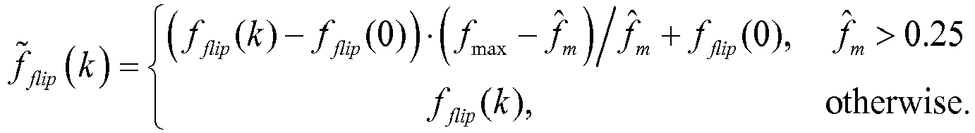
- f ⁇ flip k ⁇ f flip k ⁇ f flip 0 ⁇ f max ⁇ f ⁇ m / f ⁇ m + f flip 0 , f ⁇ m > 0.25 f flip k , otherwise
- flipped and rescaled coefficients f ⁇ flip ( k ) are further processed in step S7 by smoothing with the rescaled frequency grids ⁇ i ( k ).
- equation (6) includes a free index i, this means that a vector f smooth ( k ) will be generated for each ⁇ i ( k ) .
- step S7 is performed in a closed loop search over all frequency grids g i , to find the one that minimizes a pre-defined criterion (described after equation (12) below).
- these constants are perceptually optimized (different sets of values are suggested, and the set that maximized quality, as reported by a panel of listeners, are finally selected).
- the values of elements in ⁇ increase as the index k increases. Since a higher index corresponds to a higher-frequency, the higher frequencies of the resulting spectrum are more influenced by ⁇ i ( k ) than by f ⁇ flip (see equation (7)). This result of this smoothing or weighted averaging is a more flat spectrum towards the high frequencies (the spectrum structure potentially introduced by f flip is progressively removed towards high frequencies).
- g max is selected close to but less than 0.5. In this example g max , is selected equal to 0.49.
- the rescaled grids g ⁇ i may be different from frame to frame, since f ⁇ ( M /2-1) in rescaling equation (5) may not be constant but vary with time.
- the codebook formed by the template grids g' is constant. In this sense the rescaled grids g ⁇ i may be considered as an adaptive codebook formed from a fixed codebook of template grids g i .
- the LSF vectors f' smooth created by the weighted sum in (7) are compared to the target LSF vector f H , and the optimal grid g' is selected as the one that minimizes the mean-squared error (MSE) between these two vectors.
- MSE mean-squared error
- SD spectral distortion
- the frequency grid codebook is obtained with a K-means clustering algorithm on a large set of LSF vectors, which has been extracted from a speech database.
- the grid vectors in equations (9) and (11) are selected as the ones that, after rescaling in accordance with equation (5) and weighted averaging with f ⁇ flip in accordance with equation (7), minimize the squared distance to f H .
- these grid vectors, when used in equation (7), give the best representation of the high-frequency LSF coefficients.
- Fig. 5 is a block diagram of an example of the encoder in accordance with the proposed technology.
- the encoder 40 includes a low-frequency encoder 10 configured to encode a low-frequency part of the parametric spectral representation f by quantizing elements of the parametric spectral representation that correspond to a low-frequency part of the audio signal.
- the encoder 40 also includes a high-frequency encoder 12 configured to encode a high-frequency part f H of the parametric spectral representation by weighted averaging based on the quantized elements f ⁇ L flipped around a quantized mirroring frequency separating the low-frequency part from the high-frequency part, and a frequency grid determined from a frequency grid codebook 24 in a closed-loop search procedure.
- the quantized entities f ⁇ L , f ⁇ m , g opt are represented by the corresponding quantization indices I f L , I m , I g , which are transmitted to the decoder.
- Fig. 6 is a block diagram of an example of the encoder in accordance with the proposed technology.
- the low-frequency encoder 10 receives the entire LSF vector f , which is split into a low-frequency part or subvector f L and a high-frequency part or subvector f H by a vector splitter 14.
- the low-frequency part is forwarded to a quantizer 16, which is configured to encode the low-frequency part f L by quantizing its elements, either by scalar or vector quantization, into a quantized low-frequency part or subvector f ⁇ L .
- At least one quantization index I f L (depending on the quantization method used) is outputted for transmission to the decoder.
- the quantized low-frequency subvector f ⁇ L and the not yet encoded high-frequency subvector f H are forwarded to the high-frequency encoder 12.
- a mirroring frequency calculator 18 is configured to calculate the quantized mirroring frequency f ⁇ m in accordance with equation (2).
- the dashed lines indicate that only the last quantized element f ⁇ (M/2-1) in f ⁇ L and the first element f ( M /2) in f H are required for this.
- the quantization index I m representing the quantized mirroring frequency f ⁇ m is outputted for transmission to the decoder.
- the quantized mirroring frequency f ⁇ m is forwarded to a quantized low-frequency subvector flipping unit 20 configured to flip the elements of the quantized low-frequency subvector f ⁇ L around the quantized mirroring frequency f ⁇ m in accordance with equation (3).
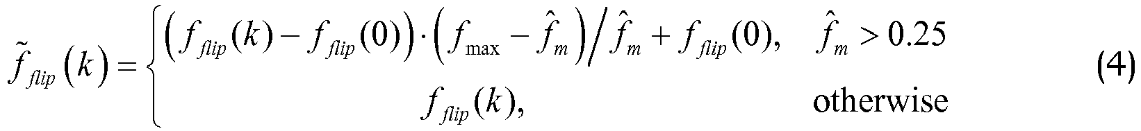
- the flipped elements f flip ( k ) and the quantized mirroring frequency f ⁇ m are forwarded to a flipped element rescaler 22 configured to rescale the flipped elements in accordance with equation (4).
- the frequency grids g' ( k ) are forwarded from frequency grid codebook 24 to a frequency grid rescaler 26, which also receives the last quantized element f ⁇ ( M / 2 -1) in f ⁇ L .
- the rescaler 26 is configured to perform rescaling in accordance with equation (5).
- the flipped and rescaled LSFs f ⁇ flip ( k ) from flipped element rescaler 22 and the rescaled frequency grids g ⁇ i ( k ) from frequency grid rescaler 26 are forwarded to a weighting unit 28, which is configured to perform a weighted averaging in accordance with equation (7).
- the resulting smoothed elements f i smooth ( k ) and the high-frequency target vector f H are forwarded to a frequency grid search unit 30 configured to select a frequency grid g opt in accordance with equation (13).
- the corresponding index I g is transmitted to the decoder.
- Fig. 7 is a flow chart of the decoding method in accordance with the proposed technology.
- Step S11 reconstructs elements of a low-frequency part of the parametric spectral representation corresponding to a low-frequency part of the audio signal from at least one quantization index encoding that part of the parametric spectral representation.
- Step S12 reconstructs elements of a high-frequency part of the parametric spectral representation by weighted averaging based on the decoded elements flipped around a decoded mirroring frequency, which separates the low-frequency part from the high-frequency part, and a decoded frequency grid.
- step S 13 the quantized low-frequency part is is reconstructed from a low-frequency codebook by using the received index I f L .
- step S16 the low- and high-frequency parts f ⁇ L , f ⁇ H of the LSF vector are combined in step S16, and the resulting vector f ⁇ is transformed to AR coefficients â in step S17.
- Fig. 9 is a block diagram of an embodiment of the decoder 50 in accordance with the proposed technology.
- a low-frequency decoder 60 is configures to reconstruct elements f ⁇ L . of a low-frequency part f L of the parametric spectral representation f corresponding to a low-frequency part of the audio signal from at least one quantization index I f L , encoding that part of the parametric spectral representation.
- a high-frequency decoder 62 is configured to reconstruct elements f ⁇ H of a high-frequency part f H of the parametric spectral representation by weighted averaging based on the decoded elements f ⁇ L flipped around a decoded mirroring frequency f ⁇ m which separates the low-frequency part from the high-frequency part, and a decoded frequency grid g opt .
- the frequency grid g opt is obtained by retrieving the frequency grid that corresponds to a received index I g from a frequency grid codebook 24 (this is the same codebook as in the encoder).
- Fig. 10 is a block diagram of an embodiment of the decoder in accordance with the proposed technology.
- the low-frequency decoder receives at least one quantization index I f L , depending on whether scalar or vector quantization is used, and forwards it to a quantization index decoder 66, which reconstructs elements f ⁇ L of the low-frequency part of the parametric spectral representation.
- the high-frequency decoder 62 receives a mirroring frequency quantization index I m , which is forwarded to a mirroring frequency decoder 66 for decoding the mirroring frequency f ⁇ m .
- the remaining blocks 20, 22, 24, 26 and 28 perform the same functions as the correspondingly numbered blocks in the encoder illustrated in Fig. 6 .
- the essential differences between the encoder and the decoder are that the mirroring frequency is decoded from the index I m instead of being calculated from equation (2), and that the frequency grid search unit 30 in the encoder is not required, since the optimal frequency grid is obtained directly from frequency grid codebook 24 by looking up the frequency grid g opt that corresponds to the received index I g .
- processing equipment may include, for example, one or several micro processors, one or several Digital Signal Processors (DSP), one or several Application Specific Integrated Circuits (ASIC), video accelerated hardware or one or several suitable programmable logic devices, such as Field Programmable Gate Arrays (FPGA). Combinations of such processing elements are also feasible.
- DSP Digital Signal Processor
- ASIC Application Specific Integrated Circuits
- FPGA Field Programmable Gate Arrays
- Fig. 11 is a block diagram of an example of the encoder 40 in accordance with the proposed technology.
- This example is based on a processor 110, for example a micro processor, which executes software 120 for quantizing the low-frequency part f L of the parametric spectral representation, and software 130 for search of an optimal extrapolation represented by the mirroring frequency f ⁇ m and the optimal frequency grid vector g opt .
- the software is stored in memory 140.
- the processor 110 communicates with the memory over a system bus.
- the incoming parametric spectral representation f is received by an input/output (I/O) controller 150 controlling an I/O bus, to which the processor 110 and the memory 140 are connected.
- the software 120 may implement the functionality of the low-frequency encoder 10.
- the software 130 may implement the functionality of the high-frequency encoder 12.
- the quantized parameters f ⁇ L , f ⁇ m , g opt (or preferably the corresponding indices I f L , I m , I g ) obtained from the software 120 and 130 are outputted from the memory 140 by the I/O controller 150 over the I/O bus.
- Fig. 12 is a block diagram of an embodiment of the decoder 50 in accordance with the proposed technology.
- This embodiment is based on a processor 210, for example a micro processor, which executes software 220 for decoding the low-frequency part f L of the parametric spectral representation, and software 230 for decoding the low-frequency part f H of the parametric spectral representation by extrapolation.
- the software is stored in memory 240.
- the processor 210 communicates with the memory over a system bus.
- the incoming encoded parameters f ⁇ L , f ⁇ m , g opt (represented by I f L , I m , I g ) are received by an input/output (I/O) controller 250 controlling an I/O bus, to which the processor 210 and the memory 240 are connected.
- the software 220 may implement the functionality of the low-frequency decoder 60.
- the software 230 may implement the functionality of the high-frequency decoder 62.
- the decoded parametric representation f ⁇ ( f ⁇ L combined with f ⁇ H ) obtained from the software 220 and 230 are outputted from the memory 240 by the I/O controller 250 over the I/O bus.
- Fig. 13 illustrates an example of a user equipment UE including an encoder in accordance with the proposed technology.
- a microphone 70 forwards an audio signal to an A/D converter 72.
- the digitized audio signal is encoded by an audio encoder 74. Only the components relevant for illustrating the proposed technology are illustrated in the audio encoder 74.
- the audio encoder 74 includes an AR coefficient estimator 76, an AR to parametric spectral representation converter 78 and an encoder 40 of the parametric spectral representation.
- the encoded parametric spectral representation (together with other encoded audio parameters that are not needed to illustrate the present technology) is forwarded to a radio unit 80 for channel encoding and up-conversion to radio frequency and transmission to a decoder over an antenna.
- Fig. 14 illustrates an embodiment of a user equipment UE including a decoder in accordance with the proposed technology.
- An antenna receives a signal including the encoded parametric spectral representation and forwards it to radio unit 82 for down-conversion from radio frequency and channel decoding.
- the resulting digital signal is forwarded to an audio decoder 84. Only the components relevant for illustrating the proposed technology are illustrated in the audio decoder 84.
- the audio decoder 84 includes a decoder 50 of the parametric spectral representation and a parametric spectral representation to AR converter 86.
- the AR coefficients are used (together with other decoded audio parameters that are not needed to illustrate the present technology) to decode the audio signal, and the resulting audio samples are forwarded to a D/A conversion and amplification unit 88, which outputs the audio signal to a loudspeaker 90.
- the proposed AR quantization-extrapolation scheme is used in a BWE context.
- AR analysis is performed on a certain high frequency band, and AR coefficients are used only for the synthesis filter.
- the excitation signal for this high band is extrapolated from an independently coded low band excitation.
- the proposed AR quantization-extrapolation scheme is used in an ACELP type coding scheme.
- ACELP coders model a speaker's vocal tract with an AR model.
- a set of AR coefficients a [ a 1 a 2 ...
- synthesized speech is generated on a frame-by-frame basis by sending the reconstructed excitation signal through the reconstructed synthesis filter A ( z ) -1 .
- the proposed AR quantization-extrapolation scheme is used as an efficient way to parameterize a spectrum envelope of a transform audio codec.
- the waveform is transformed to frequency domain, and the frequency response of the AR coefficients is used to approximate the spectrum envelope and normalize transformed vector (to create a residual vector).
- the AR coefficients and the residual vector are coded and transmitted to the decoder.
Landscapes
- Engineering & Computer Science (AREA)
- Physics & Mathematics (AREA)
- Spectroscopy & Molecular Physics (AREA)
- Audiology, Speech & Language Pathology (AREA)
- Signal Processing (AREA)
- Health & Medical Sciences (AREA)
- Computational Linguistics (AREA)
- Human Computer Interaction (AREA)
- Acoustics & Sound (AREA)
- Multimedia (AREA)
- Quality & Reliability (AREA)
- Compression, Expansion, Code Conversion, And Decoders (AREA)
- Error Detection And Correction (AREA)
Description
- The proposed technology relates to audio decoding based on an efficient representation of auto-regressive (AR) coefficients.
- AR analysis is commonly used in both time [1] and transform domain audio coding [2]. Different applications use AR vectors of different length (model order is mainly dependent on the bandwidth of the coded signal; from 10 coefficients for signals with a bandwidth of 4 kHz, to 24 coefficients for signals with a bandwidth of 16 kHz). These AR coefficients are quantized with split, multistage vector quantization (VQ), which guarantees nearly transparent reconstruction. However, conventional quantization schemes are not designed for the case when AR coefficients model high audio frequencies (for example above 6 kHz), and operate at very limited bit-budgets (which do not allow transparent coding of the coefficients). This introduces large perceptual errors in the reconstructed signal when these conventional quantization schemes are used at not optimal frequency ranges and not optimal bitrates.
-
EP1818913A1 discloses a wideband coding apparatus and method that encodes wideband LSPs using quantized narrow-band LSPs of a speech signal, and a wide-band LSP prediction device and others capable of predicting a wide-band LSP from a narrow-band LSP with a high quantization efficiency and a high accuracy while suppressing the size of a conversion table correlating the narrow-band LSP to the wide-band LSP. - An object of the proposed technology is a more efficient quantization scheme for the auto-regressive coefficients.
- This object is achieved in accordance with the attached claims.
- The proposed technology provides a low-bitrate scheme for compression or encoding of auto-regressive coefficients. In addition to perceptual improvements, the proposed technology also has the advantage of reducing the computational complexity in comparison to full-spectrum-quantization methods.
- The proposed technology, together with further objects and advantages thereof, may best be understood by making reference to the following description taken together with the accompanying drawings, in which:
-
Fig. 1 is a flow chart of the encoding method in accordance with the proposed technology; -
Fig. 2 illustrates an example of the encoder side method of the proposed technology; -
Fig. 3 illustrates flipping of quantized low-frequency LSF elements (represented by black dots) to high frequency by mirroring them to the space previously occupied by the upper half of the LSF vector; -
Fig. 4 illustrates the effect of grid smoothing on a signal spectrum; -
Fig. 5 is a block diagram of an example of the encoder in accordance with the proposed technology; -
Fig. 6 is a block diagram of an example of the encoder in accordance with the proposed technology; -
Fig. 7 is a flow chart of the decoding method in accordance with the proposed technology; -
Fig. 8 illustrates an embodiment of the decoder side method of the proposed technology; -
Fig. 9 is a block diagram of an embodiment of the decoder in accordance with the proposed technology; -
Fig. 10 is a block diagram of an embodiment of the decoder in accordance with the proposed technology; -
Fig. 11 is a block diagram of an example of the encoder in accordance with the proposed technology; -
Fig. 12 is a block diagram of an embodiment of the decoder in accordance with the proposed technology; -
Fig. 13 illustrates an example of a user equipment including an encoder in accordance with the proposed technology; and -
Fig. 14 illustrates an embodiment of a user equipment including a decoder in accordance with the proposed technology. - The proposed technology requires as input a vector a of AR coefficients (another commonly used name is linear prediction (LP) coefficients). These are typically obtained by first computing the autocorrelations r(j) of the windowed audio segment s(n), n=1,...,N , i.e.:

- In an audio communication system AR coefficients have to be efficiently transmitted from the encoder to the decoder part of the system. In the proposed technology this is achieved by quantizing only certain coefficients, and representing the remaining coefficients with only a small number of bits.
-
Fig. 1 is a flow chart of the encoding method in accordance with the proposed technology. Step S1 encodes a low-frequency part of the parametric spectral representation by quantizing elements of the parametric spectral representation that correspond to a low-frequency part of the audio signal. Step S2 encodes a high-frequency part of the parametric spectral representation by weighted averaging based on the quantized elements flipped around a quantized mirroring frequency, which separates the low-frequency part from the high-frequency part, and a frequency grid determined from a frequency grid codebook in a closed-loop search procedure. -
Fig. 2 illustrates steps performed on the encoder side of an example of the proposed technology. First the AR coefficients are converted to an Line Spectral frequencies (LSF) representation in step S3, e.g. by the algorithm described in [4]. Then the LSF vector f is split into two parts, denoted as low (L) and high-frequency (H) parts in step S4. For example in a 10 dimensional LSF vector the first 5 coefficients may be assigned to the L subvector fL and the remaining coefficients to the H subvector fH. - Although the proposed technology will be described with reference to an LSF representation, the general concepts may also be applied to an alternative implementation in which the AR vector is converted to another parametric spectral representation, such as Line Spectral Pair (LSP) or Immitance Spectral Pairs (ISP) instead of LSF.
- Only the low-frequency LSF subvector fL is quantized in step S5, and its quantization indices If
L are transmitted to the decoder. The high-frequency LSFs of the subvector fH are not quantized, but only used in the quantization of a mirroring frequency fm (to f̂m ), and the closed loop search for an optimal frequency grid gopt from a set of frequency grids gi forming a frequency grid codebook, as described with reference to equations (2)-(13) below. The quantization indices Im and Ig for the mirroring frequency and optimal frequency grid, respectively, represent the coded high-frequency LSF vector fH and are transmitted to the decoder. The encoding of the high-frequency subvector fH will occasionally be referred to as "extrapolation" in the following description. - In the proposed example quantization is based on a set of scalar quantizers (SQs) individually optimized on the statistical properties of the above parameters. In an alternative implementation the LSF elements could be sent to a vector quantizer (VQ) or one can even train a VQ for the combined set of parameters (LSFs, mirroring frequency, and optimal grid).
- The low-frequency LSFs of subvector fL are in step S6 flipped into the space spanned by the high-frequency LSFs of subvector fH .This operation is illustrated in
Fig. 3 . First the quantized mirroring frequency f̂m is calculated in accordance with:
- Next the flipped LSFs fflip (k) are calculated in accordance with:

- Then the flipped LSFs are rescaled so that they will be bound within the range [0...0.5] (as an alternative the range can be represented in radians as [0...π]) in accordance with:
- The frequency grids gi are rescaled to fit into the interval between the last quantized LSF element f̂(M/2-1) and a maximum grid point value g max, i.e.:

- These flipped and rescaled coefficients f̂flip (k) (collectively denoted f̂H in
Fig. 2 ) are further processed in step S7 by smoothing with the rescaled frequency grids ĝi (k). Smoothing has the form of a weighted sum between flipped and rescaled LSFs f̂flip (k) and the rescaled frequency grids ĝi (k), in accordance with:
- Since equation (6) includes a free index i, this means that a vector fsmooth (k) will be generated for each ĝi (k). Thus, equation (6) may be expressed as:

- The smoothing is performed step S7 in a closed loop search over all frequency grids gi , to find the one that minimizes a pre-defined criterion (described after equation (12) below).
- For M/2=5 the weights λ(k) in equation (7) can be chosen as:

- In an example these constants are perceptually optimized (different sets of values are suggested, and the set that maximized quality, as reported by a panel of listeners, are finally selected). Generally the values of elements in λ increase as the index k increases. Since a higher index corresponds to a higher-frequency, the higher frequencies of the resulting spectrum are more influenced by ĝi (k) than by f̂flip (see equation (7)). This result of this smoothing or weighted averaging is a more flat spectrum towards the high frequencies (the spectrum structure potentially introduced by fflip is progressively removed towards high frequencies).
- Here g max, is selected close to but less than 0.5. In this example g max, is selected equal to 0.49.
- The method in this example uses 4 trained grids gi (less or more grids are possible). Template grid vectors on a range [0...1], pre-stored in memory, are of the form:
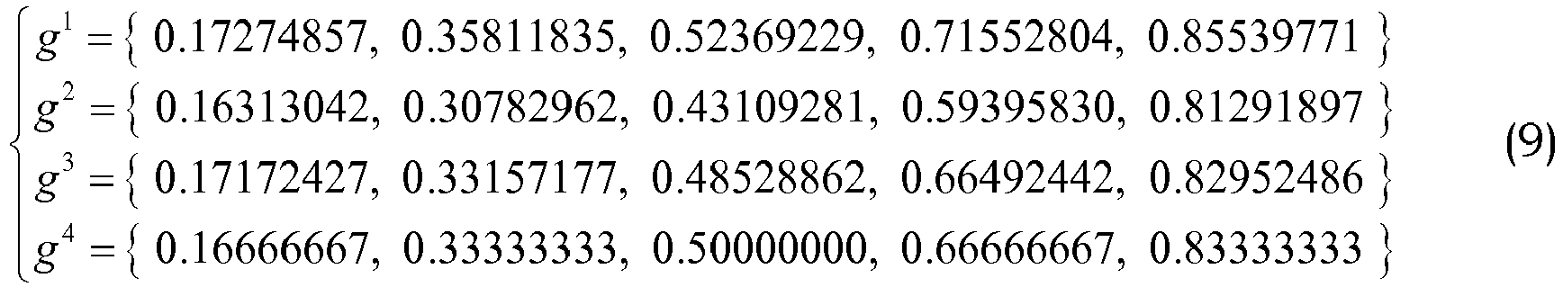
- If we assume that the position of the last quantized LSF coefficient f̂(M/2-1) is 0.25, the rescaled grid vectors take the form:

- An example of the effect of smoothing the flipped and rescaled LSF coefficients to the grid points is illustrated in
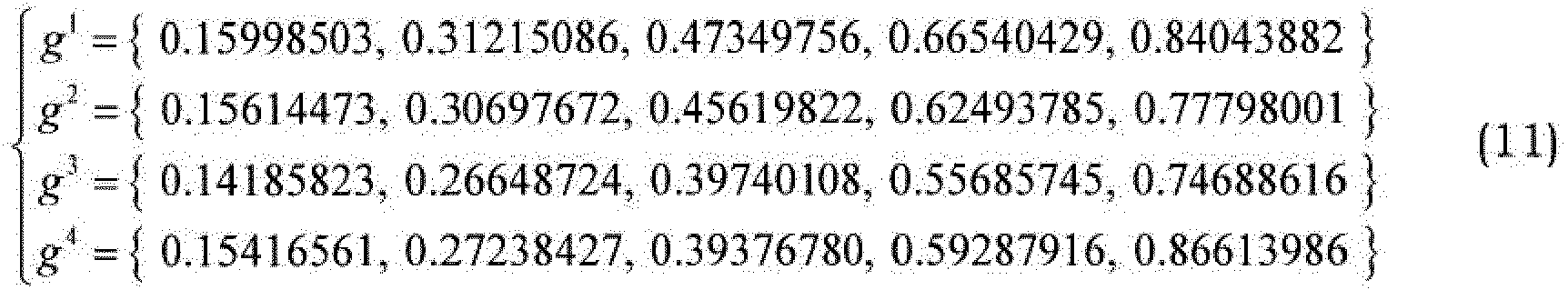
Figure 4 . With increasing number of grid vectors used in the closed loop procedure, the resulting spectrum gets closer and closer to the target spectrum. - If g max = 0.5 instead of 0.49, the frequency grid codebook may instead be formed by:
- If we again assume that the position of the last quantized LSF coefficient f̂(M/2-1) is 0.25, the rescaled grid vectors take the form:
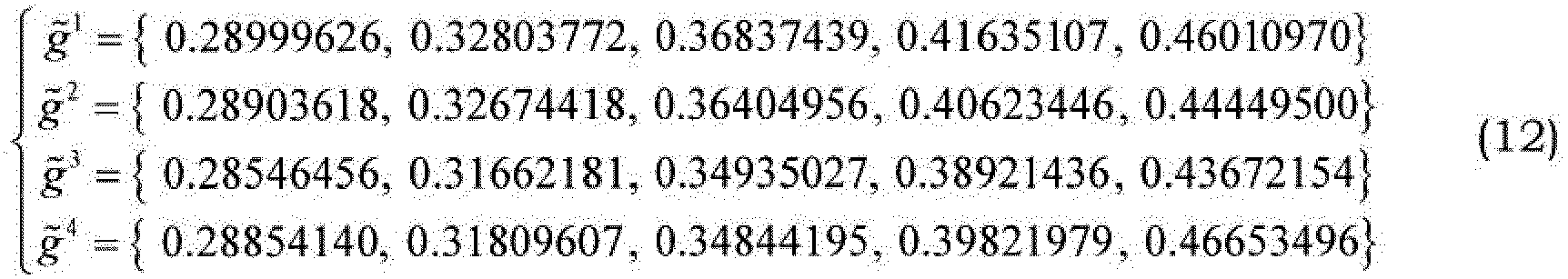
- It is noted that the rescaled grids g̃i may be different from frame to frame, since f̂(M/2-1) in rescaling equation (5) may not be constant but vary with time. However, the codebook formed by the template grids g' is constant. In this sense the rescaled grids g̃i may be considered as an adaptive codebook formed from a fixed codebook of template grids gi .
- The LSF vectors f'smooth created by the weighted sum in (7) are compared to the target LSF vector fH , and the optimal grid g' is selected as the one that minimizes the mean-squared error (MSE) between these two vectors. The index opt of this optimal grid may mathematically be expressed as:

- In an alternative implementation one can use more advanced error measures that mimic spectral distortion (SD), e.g., inverse harmonic mean or other weighting on the LSF domain.
- In an example the frequency grid codebook is obtained with a K-means clustering algorithm on a large set of LSF vectors, which has been extracted from a speech database. The grid vectors in equations (9) and (11) are selected as the ones that, after rescaling in accordance with equation (5) and weighted averaging with f̃flip in accordance with equation (7), minimize the squared distance to fH. In other words these grid vectors, when used in equation (7), give the best representation of the high-frequency LSF coefficients.
-
Fig. 5 is a block diagram of an example of the encoder in accordance with the proposed technology. Theencoder 40 includes a low-frequency encoder 10 configured to encode a low-frequency part of the parametric spectral representation f by quantizing elements of the parametric spectral representation that correspond to a low-frequency part of the audio signal. Theencoder 40 also includes a high-frequency encoder 12 configured to encode a high-frequency part fH of the parametric spectral representation by weighted averaging based on the quantized elements f̂L flipped around a quantized mirroring frequency separating the low-frequency part from the high-frequency part, and a frequency grid determined from afrequency grid codebook 24 in a closed-loop search procedure. The quantized entities f̂L , f̂m , gopt are represented by the corresponding quantization indices IfL , Im, Ig, which are transmitted to the decoder. -
Fig. 6 is a block diagram of an example of the encoder in accordance with the proposed technology. The low-frequency encoder 10 receives the entire LSF vector f , which is split into a low-frequency part or subvector fL and a high-frequency part or subvector fH by avector splitter 14. The low-frequency part is forwarded to aquantizer 16, which is configured to encode the low-frequency part fL by quantizing its elements, either by scalar or vector quantization, into a quantized low-frequency part or subvector f̂L. At least one quantization index IfL (depending on the quantization method used) is outputted for transmission to the decoder. - The quantized low-frequency subvector f̂L and the not yet encoded high-frequency subvector fH are forwarded to the high-
frequency encoder 12. Amirroring frequency calculator 18 is configured to calculate the quantized mirroring frequency f̂m in accordance with equation (2). The dashed lines indicate that only the last quantized element f̂(M/2-1) in f̂L and the first element f(M/2) in fH are required for this. The quantization index Im representing the quantized mirroring frequency f̂m is outputted for transmission to the decoder. - The quantized mirroring frequency f̂m is forwarded to a quantized low-frequency
subvector flipping unit 20 configured to flip the elements of the quantized low-frequency subvector f̂L around the quantized mirroring frequency f̂m in accordance with equation (3). The flipped elements fflip (k) and the quantized mirroring frequency f̂m are forwarded to a flippedelement rescaler 22 configured to rescale the flipped elements in accordance with equation (4). - The frequency grids g'(k) are forwarded from frequency grid codebook 24 to a
frequency grid rescaler 26, which also receives the last quantized element f̂(M / 2 -1) in f̂L . Therescaler 26 is configured to perform rescaling in accordance with equation (5). - The flipped and rescaled LSFs f̂flip (k) from flipped
element rescaler 22 and the rescaled frequency grids g̃i (k) fromfrequency grid rescaler 26 are forwarded to aweighting unit 28, which is configured to perform a weighted averaging in accordance with equation (7). The resulting smoothed elements fi smooth (k) and the high-frequency target vector fH are forwarded to a frequencygrid search unit 30 configured to select a frequency grid gopt in accordance with equation (13). The corresponding index Ig is transmitted to the decoder. -
Fig. 7 is a flow chart of the decoding method in accordance with the proposed technology. Step S11 reconstructs elements of a low-frequency part of the parametric spectral representation corresponding to a low-frequency part of the audio signal from at least one quantization index encoding that part of the parametric spectral representation. Step S12 reconstructs elements of a high-frequency part of the parametric spectral representation by weighted averaging based on the decoded elements flipped around a decoded mirroring frequency, which separates the low-frequency part from the high-frequency part, and a decoded frequency grid. - The method steps performed at the decoder are illustrated by the embodiment in
Fig. 8 . First the quantization indices IfL , Im , Ig for the low-frequency LSFs, optimal mirroring frequency and optimal grid, respectively, are received. - In step S 13 the quantized low-frequency part is is reconstructed from a low-frequency codebook by using the received index If
L . - The method steps performed at the decoder for reconstructing the high-frequency part f̂H are very similar to already described encoder processing steps in equations (3)-(7).
- The flipping and rescaling steps performed at the decoder (at S14) are identical to the encoder operations, and therefore described exactly by equations (3)-(4).
- The steps (at S15) of rescaling the grid (equation (5)), and smoothing with it (equation (6)), require only slight modification in the decoder, because the closed loop search is not performed (search over i). This is because the decoder receives the optimal index opt from the bit stream. These equations instead take the following form:


- Finally the low- and high-frequency parts f̂L , f̂H of the LSF vector are combined in step S16, and the resulting vector f̂ is transformed to AR coefficients â in step S17.
-
Fig. 9 is a block diagram of an embodiment of thedecoder 50 in accordance with the proposed technology. A low-frequency decoder 60 is configures to reconstruct elements f̂L . of a low-frequency part fL of the parametric spectral representation f corresponding to a low-frequency part of the audio signal from at least one quantization index IfL , encoding that part of the parametric spectral representation. A high-frequency decoder 62 is configured to reconstruct elements f̂H of a high-frequency part fH of the parametric spectral representation by weighted averaging based on the decoded elements f̂L flipped around a decoded mirroring frequency f̂m which separates the low-frequency part from the high-frequency part, and a decoded frequency grid gopt . The frequency grid gopt is obtained by retrieving the frequency grid that corresponds to a received index Ig from a frequency grid codebook 24 (this is the same codebook as in the encoder).. -
Fig. 10 is a block diagram of an embodiment of the decoder in accordance with the proposed technology. The low-frequency decoder receives at least one quantization index IfL , depending on whether scalar or vector quantization is used, and forwards it to aquantization index decoder 66, which reconstructs elements f̂L of the low-frequency part of the parametric spectral representation. The high-frequency decoder 62 receives a mirroring frequency quantization index Im , which is forwarded to amirroring frequency decoder 66 for decoding the mirroring frequency f̂m . The remainingblocks Fig. 6 . The essential differences between the encoder and the decoder are that the mirroring frequency is decoded from the index Im instead of being calculated from equation (2), and that the frequencygrid search unit 30 in the encoder is not required, since the optimal frequency grid is obtained directly fromfrequency grid codebook 24 by looking up the frequency grid gopt that corresponds to the received index Ig . - The steps, functions, procedures and/or blocks described herein may be implemented in hardware using any conventional technology, such as discrete circuit or integrated circuit technology, including both general-purpose electronic circuitry and application-specific circuitry.
- Alternatively, at least some of the steps, functions, procedures and/or blocks described herein may be implemented in software for execution by suitable processing equipment. This equipment may include, for example, one or several micro processors, one or several Digital Signal Processors (DSP), one or several Application Specific Integrated Circuits (ASIC), video accelerated hardware or one or several suitable programmable logic devices, such as Field Programmable Gate Arrays (FPGA). Combinations of such processing elements are also feasible.
- It should also be understood that it may be possible to reuse the general processing capabilities already present in a UE. This may, for example, be done by reprogramming of the existing software or by adding new software components.
-
Fig. 11 is a block diagram of an example of theencoder 40 in accordance with the proposed technology. This example is based on aprocessor 110, for example a micro processor, which executessoftware 120 for quantizing the low-frequency part fL of the parametric spectral representation, andsoftware 130 for search of an optimal extrapolation represented by the mirroring frequency f̂m and the optimal frequency grid vector gopt . The software is stored inmemory 140. Theprocessor 110 communicates with the memory over a system bus. The incoming parametric spectral representation f is received by an input/output (I/O)controller 150 controlling an I/O bus, to which theprocessor 110 and thememory 140 are connected. Thesoftware 120 may implement the functionality of the low-frequency encoder 10. Thesoftware 130 may implement the functionality of the high-frequency encoder 12. The quantized parameters f̂L , f̂m , gopt (or preferably the corresponding indices IfL , Im , Ig ) obtained from thesoftware memory 140 by the I/O controller 150 over the I/O bus. -
Fig. 12 is a block diagram of an embodiment of thedecoder 50 in accordance with the proposed technology. This embodiment is based on aprocessor 210, for example a micro processor, which executessoftware 220 for decoding the low-frequency part fL of the parametric spectral representation, andsoftware 230 for decoding the low-frequency part fH of the parametric spectral representation by extrapolation. The software is stored inmemory 240. Theprocessor 210 communicates with the memory over a system bus. The incoming encoded parameters f̂L, f̂m, gopt (represented by IfL , Im , Ig ) are received by an input/output (I/O)controller 250 controlling an I/O bus, to which theprocessor 210 and thememory 240 are connected. Thesoftware 220 may implement the functionality of the low-frequency decoder 60. Thesoftware 230 may implement the functionality of the high-frequency decoder 62. The decoded parametric representation f̂ (f̂L combined with f̂H ) obtained from thesoftware memory 240 by the I/O controller 250 over the I/O bus. -
Fig. 13 illustrates an example of a user equipment UE including an encoder in accordance with the proposed technology. Amicrophone 70 forwards an audio signal to an A/D converter 72. The digitized audio signal is encoded by anaudio encoder 74. Only the components relevant for illustrating the proposed technology are illustrated in theaudio encoder 74. Theaudio encoder 74 includes anAR coefficient estimator 76, an AR to parametricspectral representation converter 78 and anencoder 40 of the parametric spectral representation. The encoded parametric spectral representation (together with other encoded audio parameters that are not needed to illustrate the present technology) is forwarded to aradio unit 80 for channel encoding and up-conversion to radio frequency and transmission to a decoder over an antenna. -
Fig. 14 illustrates an embodiment of a user equipment UE including a decoder in accordance with the proposed technology. An antenna receives a signal including the encoded parametric spectral representation and forwards it toradio unit 82 for down-conversion from radio frequency and channel decoding. The resulting digital signal is forwarded to anaudio decoder 84. Only the components relevant for illustrating the proposed technology are illustrated in theaudio decoder 84. Theaudio decoder 84 includes adecoder 50 of the parametric spectral representation and a parametric spectral representation toAR converter 86. The AR coefficients are used (together with other decoded audio parameters that are not needed to illustrate the present technology) to decode the audio signal, and the resulting audio samples are forwarded to a D/A conversion andamplification unit 88, which outputs the audio signal to aloudspeaker 90. - In one example application the proposed AR quantization-extrapolation scheme is used in a BWE context. In this case AR analysis is performed on a certain high frequency band, and AR coefficients are used only for the synthesis filter. Instead of being obtained with the corresponding analysis filter, the excitation signal for this high band is extrapolated from an independently coded low band excitation.
- In another example application the proposed AR quantization-extrapolation scheme is used in an ACELP type coding scheme. ACELP coders model a speaker's vocal tract with an AR model. An excitation signal e(n) is generated by passing a waveform s(n) through a whitening filter e(n) = A(z)s(n), where A(z) =1 + a1 z -1 + a 2 z -2 + ... + aMz-M , is the AR model of order M. On a frame-by-frame basis a set of AR coefficients a = [a 1 a 2 ... aM ] T, and excitation signal are quantized, and quantization indices are transmitted over the network. At the decoder, synthesized speech is generated on a frame-by-frame basis by sending the reconstructed excitation signal through the reconstructed synthesis filter A(z)-1.
- In a further example application the proposed AR quantization-extrapolation scheme is used as an efficient way to parameterize a spectrum envelope of a transform audio codec. On short-time basis the waveform is transformed to frequency domain, and the frequency response of the AR coefficients is used to approximate the spectrum envelope and normalize transformed vector (to create a residual vector). Next the AR coefficients and the residual vector are coded and transmitted to the decoder.
- It will be understood by those skilled in the art that various modifications and changes may be made to the proposed technology without departure from the scope thereof, which is defined by the appended claims.
-
- ACELP
- Algebraic Code Excited Linear Prediction
- ASIC
- Application Specific Integrated Circuits
- AR
- Auto Regression
- BWE
- Bandwidth Extension
- DSP
- Digital Signal Processor
- FPGA
- Field Programmable Gate Array
- ISP
- Immitance Spectral Pairs
- LP
- Linear Prediction
- LSF
- Line Spectral Frequencies
- LSP
- Line Spectral Pair
- MSE
- Mean Squared Error
- SD
- Spectral Distortion
- SQ
- Scalar Quantizer
- UE
- User Equipment
- VQ
- Vector Quantization
-
- [1] 3GPP TS 26.090, "Adaptive Multi-Rate (AMR) speech codec; Trans-coding functions", p.13, 2007
- [2] N. Iwakami, et al., High-quality audio-coding at less than 64 kbit/s by using transform-domain weighted interleave vector quantization (TWINVQ), IEEE ICASSP, vol. 5, pp. 3095-3098, 1995
- [3] J. Makhoul, "Linear prediction: A tutorial review", Proc. IEEE, vol 63, p. 566, 1975
- [4] P. Kabal and R.P. Ramachandran, "The computation of line spectral frequencies using Chebyshev polynomials", IEEE Trans. on ASSP, vol. 34, no. 6, pp. 1419-1426, 1986
Claims (15)
- A method of decoding an encoded parametric spectral representation (f̂) of auto-regressive coefficients (a) that partially represent an audio signal, said method including the steps of:reconstructing (S11) coefficients (f̂L ) of a low-frequency part (fL ) of the parametric spectral representation (f) corresponding to a low-frequency part of the audio signal from at least one quantization index (If
L ) encoding that part of the parametric spectral representation;reconstructing (S12) coefficients (f̂H ) of a high-frequency part (fH ) of the parametric spectral representation by weighted averaging based on the decoded coefficients (f̂L ) flipped around a decoded mirroring frequency (f̂m ), which separates the low-frequency part from the high-frequency part, and a decoded frequency grid (gopt ). - The decoding method of claim 1, including the step of flipping the decoded coefficients (f̂L ) of the low-frequency part around the mirroring frequency f̂m in accordance with:

M denotes the total number of coefficients in the parametric spectral representation, and f̂(M/2-1-k) denotes decoded coefficient M/2-1-k. - The decoding method of claim 2, including the step of rescaling the flipped coefficients fflip (k) in accordance with:
- The decoding method of claim 3, including the step of rescaling the decoded frequency grid gopt to fit into the interval between the last quantized coefficient f̂(M/2-1) in the low-frequency part and a maximum grid point value g max in accordance with:

- The decoding method of claim 4, including the step of weighted averaging of the flipped and rescaled coefficients f̂flip (k) and the rescaled frequency grid g̃opt (k) in accordance with:

- The decoding method of claim 5, wherein M=10, g max = 0.5, and the weights λ(k) are defined as λ = { 0.2, 0.35, 0.5, 0.75, 0.8 }.
- The method of any of the preceding claims 1-6, wherein the decoding is performed on a line spectral frequencies representation of the auto-regressive coefficients.
- A decoder (50) for decoding an encoded parametric spectral representation (f̂) of auto-regressive coefficients (a) that partially represent an audio signal, said decoder including:a low-frequency decoder (60) configured to reconstruct coefficients (f̂L ) of a low-frequency part (fL ) of the parametric spectral representation (f) corresponding to a low-frequency part of the audio signal from at least one quantization index (If
L ) encoding that part of the parametric spectral representation;a high-frequency decoder (62) configured to reconstruct coefficients (f̂H ) of a high-frequency part (fH ) of the parametric spectral representation by weighted averaging based on the decoded coefficients (f̂L ) flipped around a decoded mirroring frequency (f̂m ), which separates the low-frequency part from the high-frequency part, and a decoded frequency grid (gopt ). - The decoder of claim 8, wherein the high-frequency decoder (62) includes a quantized low-frequency subvector flipping unit (20) configured to flip the decoded coefficients (f̂L ) of the low-frequency part around the mirroring frequency f̂m in accordance with:

M denotes the total number of coefficients in the parametric spectral representation, and f̂(M/2-1- k) denotes decoded coefficient M/2-1-k. - The decoder of claim 9, wherein the high-frequency decoder (62) includes a flipped element rescaler (22) configured to rescale the flipped coefficients fflip (k) in accordance with:

- The decoder of claim 10, wherein the high-frequency decoder (62) includes a frequency grid rescaler (26) configured to rescale the decoded frequency grid gopt to fit into the interval between the last quantized coefficient f̂(M/2-1) in the low-frequency part and a maximum grid point value g max, in accordance with:

- The decoder of claim 11, wherein the high-frequency decoder (62) includes a weighting unit (28) configured to perform weighted averaging of the flipped and rescaled coefficients f̂flip (k) and the rescaled frequency grid g̃opt (k) in accordance with:

- The decoder of claim 12, wherein M = 10, g max = 0.5, and the weights λ(k) are defined ass λ = { 0.2, 0.35, 0.5, 0.75, 0.8 } .
- The decoder of any of the preceding claims 8-13, wherein the decoder is configured to perform the decoding on a line spectral frequencies representation of the auto-regressive coefficients.
- A user equipment including a decoder in accordance with any of the preceding claims 8-14.
Priority Applications (3)
| Application Number | Priority Date | Filing Date | Title |
|---|---|---|---|
| PL17190535T PL3279895T3 (en) | 2011-11-02 | 2012-05-15 | Audio encoding based on an efficient representation of auto-regressive coefficients |
| EP17190535.9A EP3279895B1 (en) | 2011-11-02 | 2012-05-15 | Audio encoding based on an efficient representation of auto-regressive coefficients |
| PL16156708T PL3040988T3 (en) | 2011-11-02 | 2012-05-15 | Audio decoding based on an efficient representation of auto-regressive coefficients |
Applications Claiming Priority (2)
| Application Number | Priority Date | Filing Date | Title |
|---|---|---|---|
| US201161554647P | 2011-11-02 | 2011-11-02 | |
| EP12846533.3A EP2774146B1 (en) | 2011-11-02 | 2012-05-15 | Audio encoding based on an efficient representation of auto-regressive coefficients |
Related Parent Applications (2)
| Application Number | Title | Priority Date | Filing Date |
|---|---|---|---|
| EP12846533.3A Division EP2774146B1 (en) | 2011-11-02 | 2012-05-15 | Audio encoding based on an efficient representation of auto-regressive coefficients |
| EP12846533.3A Division-Into EP2774146B1 (en) | 2011-11-02 | 2012-05-15 | Audio encoding based on an efficient representation of auto-regressive coefficients |
Related Child Applications (2)
| Application Number | Title | Priority Date | Filing Date |
|---|---|---|---|
| EP17190535.9A Division EP3279895B1 (en) | 2011-11-02 | 2012-05-15 | Audio encoding based on an efficient representation of auto-regressive coefficients |
| EP17190535.9A Division-Into EP3279895B1 (en) | 2011-11-02 | 2012-05-15 | Audio encoding based on an efficient representation of auto-regressive coefficients |
Publications (2)
| Publication Number | Publication Date |
|---|---|
| EP3040988A1 EP3040988A1 (en) | 2016-07-06 |
| EP3040988B1 true EP3040988B1 (en) | 2017-10-25 |
Family
ID=48192964
Family Applications (3)
| Application Number | Title | Priority Date | Filing Date |
|---|---|---|---|
| EP16156708.6A Active EP3040988B1 (en) | 2011-11-02 | 2012-05-15 | Audio decoding based on an efficient representation of auto-regressive coefficients |
| EP17190535.9A Active EP3279895B1 (en) | 2011-11-02 | 2012-05-15 | Audio encoding based on an efficient representation of auto-regressive coefficients |
| EP12846533.3A Active EP2774146B1 (en) | 2011-11-02 | 2012-05-15 | Audio encoding based on an efficient representation of auto-regressive coefficients |
Family Applications After (2)
| Application Number | Title | Priority Date | Filing Date |
|---|---|---|---|
| EP17190535.9A Active EP3279895B1 (en) | 2011-11-02 | 2012-05-15 | Audio encoding based on an efficient representation of auto-regressive coefficients |
| EP12846533.3A Active EP2774146B1 (en) | 2011-11-02 | 2012-05-15 | Audio encoding based on an efficient representation of auto-regressive coefficients |
Country Status (10)
| Country | Link |
|---|---|
| US (6) | US9269364B2 (en) |
| EP (3) | EP3040988B1 (en) |
| CN (1) | CN103918028B (en) |
| AU (1) | AU2012331680B2 (en) |
| BR (1) | BR112014008376B1 (en) |
| DK (1) | DK3040988T3 (en) |
| ES (3) | ES2749967T3 (en) |
| NO (1) | NO2737459T3 (en) |
| PL (2) | PL3279895T3 (en) |
| WO (1) | WO2013066236A2 (en) |
Families Citing this family (8)
| Publication number | Priority date | Publication date | Assignee | Title |
|---|---|---|---|---|
| EP3040988B1 (en) * | 2011-11-02 | 2017-10-25 | Telefonaktiebolaget LM Ericsson (publ) | Audio decoding based on an efficient representation of auto-regressive coefficients |
| CN110223702B (en) | 2013-05-24 | 2023-04-11 | 杜比国际公司 | Audio decoding system and reconstruction method |
| EP2830064A1 (en) | 2013-07-22 | 2015-01-28 | Fraunhofer-Gesellschaft zur Förderung der angewandten Forschung e.V. | Apparatus and method for decoding and encoding an audio signal using adaptive spectral tile selection |
| CN105761723B (en) | 2013-09-26 | 2019-01-15 | 华为技术有限公司 | A kind of high-frequency excitation signal prediction technique and device |
| CN104517610B (en) * | 2013-09-26 | 2018-03-06 | 华为技术有限公司 | Method and device for frequency band extension |
| US9959876B2 (en) * | 2014-05-16 | 2018-05-01 | Qualcomm Incorporated | Closed loop quantization of higher order ambisonic coefficients |
| EP2980795A1 (en) * | 2014-07-28 | 2016-02-03 | Fraunhofer-Gesellschaft zur Förderung der angewandten Forschung e.V. | Audio encoding and decoding using a frequency domain processor, a time domain processor and a cross processor for initialization of the time domain processor |
| CN113556135B (en) * | 2021-07-27 | 2023-08-01 | 东南大学 | Polar Code Belief Propagation Bit Flip Decoding Method Based on Frozen Flip List |
Family Cites Families (9)
| Publication number | Priority date | Publication date | Assignee | Title |
|---|---|---|---|---|
| KR100701452B1 (en) * | 2000-05-17 | 2007-03-29 | 코닌클리케 필립스 일렉트로닉스 엔.브이. | Spectral modeling |
| EP1336175A1 (en) * | 2000-11-09 | 2003-08-20 | Koninklijke Philips Electronics N.V. | Wideband extension of telephone speech for higher perceptual quality |
| JP4546464B2 (en) * | 2004-04-27 | 2010-09-15 | パナソニック株式会社 | Scalable encoding apparatus, scalable decoding apparatus, and methods thereof |
| JP2008510197A (en) * | 2004-08-17 | 2008-04-03 | コーニンクレッカ フィリップス エレクトロニクス エヌ ヴィ | Scalable audio coding |
| KR20070051878A (en) | 2004-09-06 | 2007-05-18 | 마츠시타 덴끼 산교 가부시키가이샤 | Scalable coding apparatus and scalable coding method |
| CN101076853B (en) * | 2004-12-10 | 2010-10-13 | 松下电器产业株式会社 | Wideband coding device, wideband line spectrum pair prediction device, band scalable coding device, and wideband coding method |
| KR101565919B1 (en) * | 2006-11-17 | 2015-11-05 | 삼성전자주식회사 | Method and apparatus for encoding and decoding high frequency signal |
| MY208222A (en) * | 2009-01-16 | 2025-04-25 | Dolby Int Ab | Cross product enhanced harmonic transposition |
| EP3040988B1 (en) * | 2011-11-02 | 2017-10-25 | Telefonaktiebolaget LM Ericsson (publ) | Audio decoding based on an efficient representation of auto-regressive coefficients |
-
2012
- 2012-05-15 EP EP16156708.6A patent/EP3040988B1/en active Active
- 2012-05-15 ES ES17190535T patent/ES2749967T3/en active Active
- 2012-05-15 CN CN201280053667.7A patent/CN103918028B/en active Active
- 2012-05-15 US US14/355,031 patent/US9269364B2/en active Active
- 2012-05-15 ES ES16156708.6T patent/ES2657802T3/en active Active
- 2012-05-15 DK DK16156708.6T patent/DK3040988T3/en active
- 2012-05-15 EP EP17190535.9A patent/EP3279895B1/en active Active
- 2012-05-15 PL PL17190535T patent/PL3279895T3/en unknown
- 2012-05-15 ES ES12846533.3T patent/ES2592522T3/en active Active
- 2012-05-15 PL PL16156708T patent/PL3040988T3/en unknown
- 2012-05-15 BR BR112014008376-2A patent/BR112014008376B1/en active IP Right Grant
- 2012-05-15 EP EP12846533.3A patent/EP2774146B1/en active Active
- 2012-05-15 AU AU2012331680A patent/AU2012331680B2/en active Active
- 2012-05-15 WO PCT/SE2012/050520 patent/WO2013066236A2/en not_active Ceased
- 2012-07-26 NO NO12818353A patent/NO2737459T3/no unknown
-
2016
- 2016-01-13 US US14/994,561 patent/US20160155450A1/en not_active Abandoned
-
2020
- 2020-03-27 US US16/832,597 patent/US11011181B2/en active Active
-
2021
- 2021-03-12 US US17/199,869 patent/US11594236B2/en active Active
-
2023
- 2023-01-31 US US18/103,871 patent/US12087314B2/en active Active
-
2024
- 2024-08-08 US US18/798,215 patent/US20240404539A1/en active Pending
Non-Patent Citations (1)
| Title |
|---|
| None * |
Also Published As
| Publication number | Publication date |
|---|---|
| PL3279895T3 (en) | 2020-03-31 |
| WO2013066236A2 (en) | 2013-05-10 |
| EP2774146A2 (en) | 2014-09-10 |
| US11594236B2 (en) | 2023-02-28 |
| US20160155450A1 (en) | 2016-06-02 |
| US20240404539A1 (en) | 2024-12-05 |
| WO2013066236A3 (en) | 2013-07-11 |
| NO2737459T3 (en) | 2018-09-08 |
| US20140249828A1 (en) | 2014-09-04 |
| CN103918028B (en) | 2016-09-14 |
| AU2012331680B2 (en) | 2016-03-03 |
| EP3040988A1 (en) | 2016-07-06 |
| DK3040988T3 (en) | 2018-01-08 |
| AU2012331680A1 (en) | 2014-05-22 |
| PL3040988T3 (en) | 2018-03-30 |
| EP3279895B1 (en) | 2019-07-10 |
| US20210201924A1 (en) | 2021-07-01 |
| EP2774146B1 (en) | 2016-07-06 |
| BR112014008376A2 (en) | 2017-04-18 |
| BR112014008376B1 (en) | 2021-01-05 |
| US12087314B2 (en) | 2024-09-10 |
| EP2774146A4 (en) | 2015-05-13 |
| US20200243098A1 (en) | 2020-07-30 |
| EP3279895A1 (en) | 2018-02-07 |
| ES2657802T3 (en) | 2018-03-06 |
| US11011181B2 (en) | 2021-05-18 |
| ES2592522T3 (en) | 2016-11-30 |
| CN103918028A (en) | 2014-07-09 |
| US20230178087A1 (en) | 2023-06-08 |
| US9269364B2 (en) | 2016-02-23 |
| ES2749967T3 (en) | 2020-03-24 |
Similar Documents
| Publication | Publication Date | Title |
|---|---|---|
| US12087314B2 (en) | Audio encoding/decoding based on an efficient representation of auto-regressive coefficients | |
| EP3301674B1 (en) | Adaptive bandwidth extension and apparatus for the same | |
| CA2556797C (en) | Methods and devices for low-frequency emphasis during audio compression based on acelp/tcx | |
| EP4195203B1 (en) | Determining a weighting function having low complexity for linear predictive coding (lpc) coefficients quantization | |
| US20070147518A1 (en) | Methods and devices for low-frequency emphasis during audio compression based on ACELP/TCX | |
| US20130246055A1 (en) | System and Method for Post Excitation Enhancement for Low Bit Rate Speech Coding | |
| WO2009125588A1 (en) | Encoding device and encoding method | |
| WO2012053149A1 (en) | Speech analyzing device, quantization device, inverse quantization device, and method for same |
Legal Events
| Date | Code | Title | Description |
|---|---|---|---|
| PUAI | Public reference made under article 153(3) epc to a published international application that has entered the european phase |
Free format text: ORIGINAL CODE: 0009012 |
|
| AC | Divisional application: reference to earlier application |
Ref document number: 2774146 Country of ref document: EP Kind code of ref document: P |
|
| AK | Designated contracting states |
Kind code of ref document: A1 Designated state(s): AL AT BE BG CH CY CZ DE DK EE ES FI FR GB GR HR HU IE IS IT LI LT LU LV MC MK MT NL NO PL PT RO RS SE SI SK SM TR |
|
| 17P | Request for examination filed |
Effective date: 20161130 |
|
| RBV | Designated contracting states (corrected) |
Designated state(s): AL AT BE BG CH CY CZ DE DK EE ES FI FR GB GR HR HU IE IS IT LI LT LU LV MC MK MT NL NO PL PT RO RS SE SI SK SM TR |
|
| RIC1 | Information provided on ipc code assigned before grant |
Ipc: G10L 19/032 20130101ALI20170412BHEP Ipc: G10L 19/06 20130101AFI20170412BHEP Ipc: G10L 21/038 20130101ALI20170412BHEP Ipc: G10L 19/02 20130101ALN20170412BHEP |
|
| GRAP | Despatch of communication of intention to grant a patent |
Free format text: ORIGINAL CODE: EPIDOSNIGR1 |
|
| INTG | Intention to grant announced |
Effective date: 20170519 |
|
| GRAS | Grant fee paid |
Free format text: ORIGINAL CODE: EPIDOSNIGR3 |
|
| GRAA | (expected) grant |
Free format text: ORIGINAL CODE: 0009210 |
|
| AC | Divisional application: reference to earlier application |
Ref document number: 2774146 Country of ref document: EP Kind code of ref document: P |
|
| AK | Designated contracting states |
Kind code of ref document: B1 Designated state(s): AL AT BE BG CH CY CZ DE DK EE ES FI FR GB GR HR HU IE IS IT LI LT LU LV MC MK MT NL NO PL PT RO RS SE SI SK SM TR |
|
| REG | Reference to a national code |
Ref country code: GB Ref legal event code: FG4D |
|
| REG | Reference to a national code |
Ref country code: CH Ref legal event code: EP Ref country code: CH Ref legal event code: NV Representative=s name: ISLER AND PEDRAZZINI AG, CH |
|
| REG | Reference to a national code |
Ref country code: AT Ref legal event code: REF Ref document number: 940613 Country of ref document: AT Kind code of ref document: T Effective date: 20171115 |
|
| REG | Reference to a national code |
Ref country code: IE Ref legal event code: FG4D |
|
| REG | Reference to a national code |
Ref country code: DE Ref legal event code: R096 Ref document number: 602012039099 Country of ref document: DE |
|
| REG | Reference to a national code |
Ref country code: DK Ref legal event code: T3 Effective date: 20180105 |
|
| REG | Reference to a national code |
Ref country code: NL Ref legal event code: FP |
|
| REG | Reference to a national code |
Ref country code: NO Ref legal event code: T2 Effective date: 20171025 |
|
| REG | Reference to a national code |
Ref country code: ES Ref legal event code: FG2A Ref document number: 2657802 Country of ref document: ES Kind code of ref document: T3 Effective date: 20180306 |
|
| REG | Reference to a national code |
Ref country code: LT Ref legal event code: MG4D |
|
| REG | Reference to a national code |
Ref country code: AT Ref legal event code: MK05 Ref document number: 940613 Country of ref document: AT Kind code of ref document: T Effective date: 20171025 |
|
| PG25 | Lapsed in a contracting state [announced via postgrant information from national office to epo] |
Ref country code: SE Free format text: LAPSE BECAUSE OF FAILURE TO SUBMIT A TRANSLATION OF THE DESCRIPTION OR TO PAY THE FEE WITHIN THE PRESCRIBED TIME-LIMIT Effective date: 20171025 Ref country code: FI Free format text: LAPSE BECAUSE OF FAILURE TO SUBMIT A TRANSLATION OF THE DESCRIPTION OR TO PAY THE FEE WITHIN THE PRESCRIBED TIME-LIMIT Effective date: 20171025 Ref country code: LT Free format text: LAPSE BECAUSE OF FAILURE TO SUBMIT A TRANSLATION OF THE DESCRIPTION OR TO PAY THE FEE WITHIN THE PRESCRIBED TIME-LIMIT Effective date: 20171025 |
|
| REG | Reference to a national code |
Ref country code: FR Ref legal event code: PLFP Year of fee payment: 7 |
|
| PG25 | Lapsed in a contracting state [announced via postgrant information from national office to epo] |
Ref country code: LV Free format text: LAPSE BECAUSE OF FAILURE TO SUBMIT A TRANSLATION OF THE DESCRIPTION OR TO PAY THE FEE WITHIN THE PRESCRIBED TIME-LIMIT Effective date: 20171025 Ref country code: GR Free format text: LAPSE BECAUSE OF FAILURE TO SUBMIT A TRANSLATION OF THE DESCRIPTION OR TO PAY THE FEE WITHIN THE PRESCRIBED TIME-LIMIT Effective date: 20180126 Ref country code: BG Free format text: LAPSE BECAUSE OF FAILURE TO SUBMIT A TRANSLATION OF THE DESCRIPTION OR TO PAY THE FEE WITHIN THE PRESCRIBED TIME-LIMIT Effective date: 20180125 Ref country code: IS Free format text: LAPSE BECAUSE OF FAILURE TO SUBMIT A TRANSLATION OF THE DESCRIPTION OR TO PAY THE FEE WITHIN THE PRESCRIBED TIME-LIMIT Effective date: 20180225 Ref country code: AT Free format text: LAPSE BECAUSE OF FAILURE TO SUBMIT A TRANSLATION OF THE DESCRIPTION OR TO PAY THE FEE WITHIN THE PRESCRIBED TIME-LIMIT Effective date: 20171025 Ref country code: HR Free format text: LAPSE BECAUSE OF FAILURE TO SUBMIT A TRANSLATION OF THE DESCRIPTION OR TO PAY THE FEE WITHIN THE PRESCRIBED TIME-LIMIT Effective date: 20171025 Ref country code: RS Free format text: LAPSE BECAUSE OF FAILURE TO SUBMIT A TRANSLATION OF THE DESCRIPTION OR TO PAY THE FEE WITHIN THE PRESCRIBED TIME-LIMIT Effective date: 20171025 |
|
| REG | Reference to a national code |
Ref country code: DE Ref legal event code: R097 Ref document number: 602012039099 Country of ref document: DE |
|
| PG25 | Lapsed in a contracting state [announced via postgrant information from national office to epo] |
Ref country code: CY Free format text: LAPSE BECAUSE OF FAILURE TO SUBMIT A TRANSLATION OF THE DESCRIPTION OR TO PAY THE FEE WITHIN THE PRESCRIBED TIME-LIMIT Effective date: 20171025 Ref country code: EE Free format text: LAPSE BECAUSE OF FAILURE TO SUBMIT A TRANSLATION OF THE DESCRIPTION OR TO PAY THE FEE WITHIN THE PRESCRIBED TIME-LIMIT Effective date: 20171025 Ref country code: SK Free format text: LAPSE BECAUSE OF FAILURE TO SUBMIT A TRANSLATION OF THE DESCRIPTION OR TO PAY THE FEE WITHIN THE PRESCRIBED TIME-LIMIT Effective date: 20171025 |
|
| PG25 | Lapsed in a contracting state [announced via postgrant information from national office to epo] |
Ref country code: SM Free format text: LAPSE BECAUSE OF FAILURE TO SUBMIT A TRANSLATION OF THE DESCRIPTION OR TO PAY THE FEE WITHIN THE PRESCRIBED TIME-LIMIT Effective date: 20171025 Ref country code: RO Free format text: LAPSE BECAUSE OF FAILURE TO SUBMIT A TRANSLATION OF THE DESCRIPTION OR TO PAY THE FEE WITHIN THE PRESCRIBED TIME-LIMIT Effective date: 20171025 |
|
| PLBE | No opposition filed within time limit |
Free format text: ORIGINAL CODE: 0009261 |
|
| STAA | Information on the status of an ep patent application or granted ep patent |
Free format text: STATUS: NO OPPOSITION FILED WITHIN TIME LIMIT |
|
| 26N | No opposition filed |
Effective date: 20180726 |
|
| PG25 | Lapsed in a contracting state [announced via postgrant information from national office to epo] |
Ref country code: SI Free format text: LAPSE BECAUSE OF FAILURE TO SUBMIT A TRANSLATION OF THE DESCRIPTION OR TO PAY THE FEE WITHIN THE PRESCRIBED TIME-LIMIT Effective date: 20171025 |
|
| PG25 | Lapsed in a contracting state [announced via postgrant information from national office to epo] |
Ref country code: MC Free format text: LAPSE BECAUSE OF FAILURE TO SUBMIT A TRANSLATION OF THE DESCRIPTION OR TO PAY THE FEE WITHIN THE PRESCRIBED TIME-LIMIT Effective date: 20171025 |
|
| REG | Reference to a national code |
Ref country code: IE Ref legal event code: MM4A |
|
| PG25 | Lapsed in a contracting state [announced via postgrant information from national office to epo] |
Ref country code: LU Free format text: LAPSE BECAUSE OF NON-PAYMENT OF DUE FEES Effective date: 20180515 |
|
| PG25 | Lapsed in a contracting state [announced via postgrant information from national office to epo] |
Ref country code: IE Free format text: LAPSE BECAUSE OF NON-PAYMENT OF DUE FEES Effective date: 20180515 |
|
| PG25 | Lapsed in a contracting state [announced via postgrant information from national office to epo] |
Ref country code: MT Free format text: LAPSE BECAUSE OF NON-PAYMENT OF DUE FEES Effective date: 20180515 |
|
| PG25 | Lapsed in a contracting state [announced via postgrant information from national office to epo] |
Ref country code: PT Free format text: LAPSE BECAUSE OF FAILURE TO SUBMIT A TRANSLATION OF THE DESCRIPTION OR TO PAY THE FEE WITHIN THE PRESCRIBED TIME-LIMIT Effective date: 20171025 |
|
| PG25 | Lapsed in a contracting state [announced via postgrant information from national office to epo] |
Ref country code: HU Free format text: LAPSE BECAUSE OF FAILURE TO SUBMIT A TRANSLATION OF THE DESCRIPTION OR TO PAY THE FEE WITHIN THE PRESCRIBED TIME-LIMIT; INVALID AB INITIO Effective date: 20120515 Ref country code: MK Free format text: LAPSE BECAUSE OF NON-PAYMENT OF DUE FEES Effective date: 20171025 |
|
| PG25 | Lapsed in a contracting state [announced via postgrant information from national office to epo] |
Ref country code: AL Free format text: LAPSE BECAUSE OF FAILURE TO SUBMIT A TRANSLATION OF THE DESCRIPTION OR TO PAY THE FEE WITHIN THE PRESCRIBED TIME-LIMIT Effective date: 20171025 |
|
| P01 | Opt-out of the competence of the unified patent court (upc) registered |
Effective date: 20230523 |
|
| PGFP | Annual fee paid to national office [announced via postgrant information from national office to epo] |
Ref country code: NL Payment date: 20250526 Year of fee payment: 14 |
|
| PGFP | Annual fee paid to national office [announced via postgrant information from national office to epo] |
Ref country code: PL Payment date: 20250418 Year of fee payment: 14 Ref country code: DE Payment date: 20250529 Year of fee payment: 14 |
|
| PGFP | Annual fee paid to national office [announced via postgrant information from national office to epo] |
Ref country code: GB Payment date: 20250527 Year of fee payment: 14 Ref country code: ES Payment date: 20250602 Year of fee payment: 14 Ref country code: DK Payment date: 20250526 Year of fee payment: 14 |
|
| PGFP | Annual fee paid to national office [announced via postgrant information from national office to epo] |
Ref country code: NO Payment date: 20250530 Year of fee payment: 14 |
|
| PGFP | Annual fee paid to national office [announced via postgrant information from national office to epo] |
Ref country code: IT Payment date: 20250521 Year of fee payment: 14 Ref country code: BE Payment date: 20250527 Year of fee payment: 14 |
|
| PGFP | Annual fee paid to national office [announced via postgrant information from national office to epo] |
Ref country code: FR Payment date: 20250526 Year of fee payment: 14 |
|
| PGFP | Annual fee paid to national office [announced via postgrant information from national office to epo] |
Ref country code: CH Payment date: 20250601 Year of fee payment: 14 |
|
| PGFP | Annual fee paid to national office [announced via postgrant information from national office to epo] |
Ref country code: TR Payment date: 20250428 Year of fee payment: 14 |
|
| PGFP | Annual fee paid to national office [announced via postgrant information from national office to epo] |
Ref country code: CZ Payment date: 20250425 Year of fee payment: 14 |