The present application is a divisional application of the patent application having application number 201780006520.5, filing date 2017, 1/12, entitled "cartridge receptacle for making a beverage, cartridge system, beverage preparation machine and method".
Disclosure of Invention
It is therefore an object of the present invention to provide a cartridge receptacle, a cartridge system, a beverage preparation machine and a method for manufacturing a beverage by inserting the cartridge system into the beverage preparation machine, wherein back contamination of the beverage preparation machine is effectively avoided.
This object is achieved by a cartridge receptacle and a cartridge system as described below.
The cartridge receptacle of the present invention and the cartridge system of the present invention have the following advantages over the prior art: unlike the prior art, the fluid supply is not introduced into the reservoir of the cartridge but into a mixing chamber separate from the reservoir. Reverse contamination of the beverage preparation machine due to the fluid supply is thereby prevented effectively and in a simple and cost-effective manner of realization. For this purpose, the reservoir is not flushed with fluid, but rather, according to the invention, the beverage substance and the fluid enter the mixing chamber separately from one another. The fluid is directed directly into the mixing chamber, while the beverage substance is transferred into the mixing chamber through the cartridge unloading means and independently of the fluid. It has been shown that reverse contamination of the beverage preparation machine is thereby suppressed in a significantly more efficient manner than in the prior art, in particular because no overpressure is generated in the reservoir which acts directly on the fluid supply. Forming the mixing chamber in a cartridge receptacle that can be reversibly inserted into the beverage preparation machine advantageously makes the mixing chamber part of a replaceable cartridge system. In this way, contamination of the beverage preparation machine by the beverage substance is effectively avoided, since only parts of the replaceable disposable cartridge or the multiple cartridge come into contact with the beverage substance. It is also conceivable that the cartridge is replaced in each beverage making process, while the cartridge receptacle is used for a number of beverage making processes, which are then also replaced. Preferably, the reservoir of the cartridge system is closed by a sealing element which is opened only when or after the cartridge system is inserted into the beverage preparation machine. The sealing element serves to hermetically seal the capsule during transport or storage, for example, so that a long shelf life of the capsule is achieved.
Advantageous embodiments and refinements of the invention can be derived from the subclaims and the description with reference to the figures.
According to a preferred embodiment of the invention, it is provided that the cartridge is fixedly or releasably connected to the cartridge receptacle, or that the cartridge receptacle can be fixedly or releasably connected to the cartridge. Preferably, the cartridge receptacle is reversibly fastened to the cartridge, particularly preferably by means of a snap connection. For example, it is conceivable that the cartridge comprises a flange neck with a surrounding retaining flange (with the cartridge opening) and that the cartridge receptacle clamps on the flange neck. In this case, a particularly elastic latching element (for example a retaining arm) engages behind the retaining collar. The capsule is particularly provided as a disposable container, particularly recyclable, for beverage substances. Advantageously, the cassette receptacle is used several times in such a way that it can be fastened to different cassettes. Furthermore, the manufacture of the cartridge system is simplified, since the cartridge and the cartridge receptacle can be manufactured separately and only then the cartridge receptacle can be clamped to the cartridge. The cassette comprises in particular angled, rounded or rounded flanges. The capsule is produced from plastic, in particular in a blow-injection molding process or in an injection molding process or using other molding processes. But in principle also a deep-drawing method for manufacturing the box is possible. Naturally, it is also conceivable that the cassette can be used several times.
According to a further preferred embodiment of the invention, it is proposed that the cartridge unloading device comprises a compressed air connection for connection to a compressed air source and a compressed air line which extends from the compressed air connection to a compressed air outlet, and wherein the compressed air outlet projects in particular in the direction of the reservoir of the cartridge in order to blow compressed air into the reservoir. In the sense of the invention, the cassette unloading device integrated into the cassette receptacle comprises firstly only one compressed air line, via which compressed air can be conducted from the outside into the reservoir. The cartridge system is formed to force the beverage substance from the reservoir into the mixing chamber by the compressed air. The compressed air is in particular provided by the beverage preparation machine. It is conceivable that the compressed air source is directly coupled to the compressed air interface once the cartridge system is inserted into the beverage preparation machine. The advantage of this is that reverse contamination in the direction of the beverage preparation machine is effectively avoided, since the cartridge unloading device is immediately under pressure when the cartridge system is inserted and thus a displacement of the beverage substance in the direction of the compressed air line and in particular in the direction of the compressed air source of the beverage preparation machine is avoided. The beverage substance can then only move from the reservoir in the direction of the mixing chamber.
According to a further preferred embodiment of the invention, it is provided that the mixing chamber has a beverage outflow opening through which a beverage formed by mixing of the beverage substance with the fluid is discharged, wherein the cartridge system is preferably formed as follows: the beverage can be directed into the portable container from the beverage outlet. In an advantageous manner, then, neither the beverage substance nor the beverage produced comes into contact with parts of the beverage maker, so that almost any (reverse) contamination of the beverage maker is prevented. The fluids are separately fed into the mixing chamber. The fluid is preferably introduced into the mixing chamber under pressure. The fluid is in particular provided by the beverage preparation machine. It is envisaged that the fluid source is directly coupled to the corresponding fluid interface of the cartridge receptacle once the cartridge system is inserted into the beverage preparation machine. The fluid connection is in fluid connection with the mixing chamber via a fluid line. This has the advantage that reverse contamination in the direction of the beverage preparation machine is effectively avoided, since the fluid connection is immediately under pressure when the cartridge system is inserted and therefore a displacement of the beverage substance in the direction of the fluid line and in particular in the direction of the fluid source of the beverage preparation machine is avoided. The beverage substance and the beverage can then only be moved from the mixing chamber in the direction of the beverage outlet. The fluid comprises in particular water, cooled and/or carbonated drinking water, preferably under pressure.
According to a preferred embodiment of the invention, it is provided that the mixing chamber is provided with a mixing structure. These mixing structures provide in an advantageous manner an improved thorough mixing of the beverage substance with the fluid. For this purpose, these mixing structures are formed in particular such that the fluid flowing into the mixing chamber swirls. It is conceivable that the mixing structures comprise one or more mixing tabs which are arranged in the region of the fluid supply at the bottom of the mixing chamber and extend substantially perpendicularly to the inflow direction of the fluid. The mixing tab thus acts as a barrier for the fluid, thereby swirling the fluid and achieving a better thorough mixing with the beverage substance.
According to a further preferred embodiment of the invention, it is proposed that the fluid supply is fed with a fluid which is cooled by a cooling assembly, wherein the cooling assembly is part of the beverage preparation machine or is a separate refrigerator in operative connection with the beverage preparation machine. Thus, in an advantageous manner, a cold drink can be made even when the cartridge is not cooled and has, for example, room temperature. The integration of this system to existing freezers has the following advantages: the already existing cooling assembly of the refrigerator can simply be used simultaneously in an efficient manner for the beverage preparation machine. Especially in the case of so-called "side-by-side" freezers (also commonly referred to as american-style freezers), there is sufficient construction space at the front to integrate the system. It is envisaged that the beverage preparation machine is a retrofit kit for such a refrigerator. The cooling assembly preferably comprises a compressor cooling unit, an absorber cooling unit or a thermoelectric refrigerator.
According to another preferred embodiment of the invention it is provided that the fluid supply is fed with a fluid to which carbonic acid is added by means of a carbonator. It is envisaged that the carbonator is part of the beverage preparation machine, and wherein the carbonator has a CO for CO2Receptacle for a tank and method for removing CO from the tank2Tank adding CO to the fluid2The supply device of (1). Thus, carbonated soft drinks can also be advantageously produced by the system. Alternatively, it is also conceivable for the carbonator to have an external CO2An interface.
According to a further preferred embodiment of the invention, it is provided that the cartridge receptacle is formed substantially in one piece or that the cartridge receptacle comprises a cover element and an outlet element connected to the cover element. In the sense of the present invention, the one-piece embodiment of the cartridge receptacle does not mean in particular that the cartridge receptacle is to be formed only by a single part, but rather that the cartridge receptacle is not formed by the cover element and the separate outlet element in this particular one-piece embodiment. In other words: in this one-piece embodiment the cover element and the outlet element are formed in one piece.
According to a further preferred embodiment of the invention, it is provided that the cover element is reversibly connectable to the cartridge and in particular lockable such that the cartridge opening leading to the reservoir is at least temporarily or partially closed by the cover element, and wherein the outlet element is reversibly connectable to the cover element and in particular lockable. To manufacture such an embodiment of the cartridge system, the cartridge is manufactured, then filled with the beverage substance through the cartridge opening and subsequently the cartridge receptacle is clamped onto the cartridge so as to close the cartridge opening. The outlet element in this case has in particular a fluid supply, a compressed air connection, a mixing chamber and a beverage outflow opening, while the cover element has a compressed air outlet which projects in particular into the reservoir in order to introduce compressed air into the reservoir. It is conceivable for the compressed air outlet to comprise a hollow tip, the compressed air outlet being in operative connection with a compressed air connection formed at the cover element or at the outlet element via the compressed air line.
According to a further preferred embodiment of the invention, it is provided that a fluid connection can be produced between the cartridge opening and the mixing chamber by means of a valve unit, wherein the valve unit can be transferred from a closed state into an open state for producing the fluid connection by a relative movement between the cover element and the outlet element. The reservoir can advantageously be opened in such a way that the beverage substance can be transferred from the reservoir into the mixing chamber by means of compressed air in such a way that a relative movement between the cover element and the outlet element is simply carried out. This relative movement may be performed before or after insertion of the cartridge system into the beverage preparation machine.
Preferably, the cover element has a through-opening leading to the cartridge opening, wherein the valve unit is formed by the through-opening and a projection of the outlet element projecting into the through-opening, wherein the projection is offset from a position closing the through-opening to a position partially releasing the through-opening by a relative movement between the cover element and the outlet element. The wall of the through-opening is provided in particular with at least one lateral channel, wherein the projection is arranged in the region of the at least one lateral channel in a position in which the through-opening is partially released. Preferably, a plurality of parallel arranged lateral channels are provided in the wall of the through-opening. The lateral channels run perpendicular to the cross-sectional area of the through-opening but in this case each extend only over a partial area of the wall. The projection has in particular an outer, circumferential sealing edge which, in the position for closing, bears against an inner wall of the through-opening and thereby closes the through-opening. By means of the relative movement, the projection is preferably pushed linearly in the direction of the reservoir or away from the reservoir, so that the outer, circumferential sealing edge reaches into the region of the lateral channel and loses its sealing effect, since the beverage substance can flow through the lateral channel past the sealing edge.
It is conceivable that the cross section of the lateral channels and/or the number of the lateral channels is adapted to the viscosity of the beverage substance, so that the lateral channels control or limit the flow of the beverage substance in the direction of the mixing chamber. At high viscosities, more lateral channels or lateral channels with a larger cross section are used, while at low viscosities, fewer lateral channels or lateral channels with a smaller cross section are provided. Thus, different cover elements (each with matching lateral channels) are preferably applied for different types of beverage substances. There is thus a matching cover element for each cassette. The projection is formed in particular as an anvil, wherein the outer circumferential sealing edge forms a cross-sectional enlargement for the base of the anvil.
In the above described embodiments, the cover element and the outlet element may be formed as separate parts, whereby the relative movement may be performed. The relative movement here includes, in particular, a linear movement of the cover element and the outlet element toward one another and a linear movement of the cover element and the outlet element away from one another in order to move the projection within the through-opening and relative to the lateral channel.
According to a further alternative preferred embodiment of the invention, it is provided that the cartridge has a cartridge opening which is in fluid connection with the reservoir, wherein the cartridge opening is closed with a sealing element, wherein the sealing element comprises in particular a sealing film which is applied and preferably seals on an edge of the cartridge opening. In this embodiment, the cartridge receptacle is formed in particular in one piece, that is to say there is no separate outlet element and cover element. In order to produce such a capsule system, a capsule having a capsule opening is first produced, then the capsule is filled with a beverage substance through the capsule opening, then the capsule opening is closed by a sealing element and finally the capsule receptacle is clamped to the capsule in the region of the closed capsule opening. Before, during or after insertion of the cartridge system into the beverage preparation machine, the sealing element has to be opened in the region of the cartridge opening, for example by perforating the sealing membrane, whereby the beverage substance can be transferred from the reservoir into the mixing chamber by introducing compressed air. Preferably, the cartridge receptacle has for this purpose a piercing tip which projects in the direction of the cartridge, such that by means of a relative movement between the cartridge receptacle and the cartridge the piercing tip pierces the sealing element and produces a fluid connection between the reservoir and the mixing chamber. It is conceivable that the cartridge is first located in a ready position within the cartridge receptacle, in which ready position the piercing tip is spaced apart from the sealing element, and that after introduction of the cartridge system into the beverage preparation machine the cartridge is transferred from the ready position into a final position, in which the piercing tip pierces the sealing element. When the cartridge system is transferred from the ready position to the final position, the cartridge and the cartridge receptacle are moved in particular further translatory movements towards each other, wherein the sealing element is actively penetrated by the puncturing tip during this movement. The piercing tip then protrudes through the sealing element towards the square of the opening of the cartridge. Preferably, when the sealing element is pierced, at least one lateral channel is introduced into the wall of the piercing tip in order to guide the beverage substance in the direction of the mixing chamber. The beverage substance can then be made to flow past the sealing element in the direction of the mixing chamber through the lateral passage formed laterally at the piercing tip. Preferably, a plurality of lateral channels are formed at the piercing tip. These lateral channels are in particular each formed in the form of a groove which is open on one side.
It is conceivable that the cross section of the lateral channels and/or the number of the lateral channels is adapted to the viscosity of the beverage substance, so that the lateral channels control or limit the flow of the beverage substance in the direction of the mixing chamber. At high viscosities, more lateral channels or lateral channels with a larger cross section are used, while at low viscosities, fewer lateral channels or lateral channels with a smaller cross section are provided. Thus there is a matching cassette receptacle for each cassette.
Preferably, the piercing tip has a through bore in which a compressed air injector is displaceably mounted between a retracted position in which the compressed air injector projects in the direction of the reservoir beyond the piercing tip and an extended position in which the compressed air injector projects beyond the piercing tip into the reservoir. Preferably, the compressed air syringe is displaced from the retracted position in the direction of the extended position after the sealing element has been pierced by the piercing tip. Compressed air is then introduced into the reservoir by means of the compressed air injector, so that the beverage substance is pressed through the recess into the mixing chamber and forms a beverage with the fluid within the mixing chamber. Preferably, a compressed air line is integrated into the compressed air injector for this purpose. A compressed air connection is formed on the side of the compressed air injector which is remote from the reservoir, wherein the compressed air connection is preferably accessible from the outside of the cartridge receptacle and can therefore be connected to a compressed air source of the beverage preparation machine. It is conceivable that the compressed air injector is transferred by the release element of the beverage preparation machine from the retracted position into the extended position upon insertion of the cartridge system into the beverage preparation machine. Compressed air is preferably already applied to the compressed air injector here to prevent any back contamination. Alternatively, the compressed air injector is moved from the retracted position into the extended position by compressed air applied on the beverage preparation machine.
In an alternative embodiment to the embodiment described above, the piercing tip is not formed fixed at or integral with the cartridge receptacle, but the cartridge receptacle comprises a tip guide and a piercing tip displaceably mounted within the tip guide. The piercing tip is displaceably mounted relative to a tip guide between a retracted position in which the piercing tip is spaced apart from the sealing element and an extended position in which the piercing tip pierces the sealing element and protrudes into the reservoir. The outer wall of the piercing tip is further provided with at least one lateral channel for guiding the beverage substance in the direction of the mixing chamber when the sealing element is pierced. The beverage substance can then be made to flow past the sealing element in the direction of the mixing chamber through the lateral passage formed laterally at the piercing tip. Preferably, a plurality of lateral channels are formed at the piercing tip. These lateral channels are in particular each formed in the form of a groove which is open on one side.
In this embodiment, it is also conceivable that the cross section of the lateral channels and/or the number of the lateral channels is adapted to the viscosity of the beverage substance, so that the lateral channels control or limit the flow of the beverage substance in the direction of the mixing chamber. At high viscosities, more lateral channels or lateral channels with a larger cross section are used, while at low viscosities, fewer lateral channels or lateral channels with a smaller cross section are provided. Thus there is a matching cassette receptacle for each cassette.
In this alternative embodiment, a compressed air line is preferably integrated into the piercing tip. However, the piercing tip does not have a movable compressed air syringe, but instead a compressed air line is introduced into the cartridge opening via a compressed air syringe fixed at the end of the piercing tip. A compressed air connection is formed on the side of the piercing point that is remote from the reservoir, wherein the compressed air connection is preferably accessible from the outside of the cartridge receptacle. Preferably, the piercing tip is transferred by a release element of the beverage preparation machine from the retracted position into the extended position upon insertion of the cartridge system into the beverage preparation machine. Compressed air is preferably already applied to the compressed air injector here in order to prevent any back contamination of the beverage preparation machine. Alternatively, the compressed air injector is moved from the retracted position into the extended position by compressed air applied on the beverage preparation machine.
According to a further preferred embodiment of the invention, it is provided that the capsule has a further capsule opening on the side opposite the capsule opening, which is closed by a further sealing element, in particular a further sealing membrane. In an advantageous manner, the cartridge can thus also be manufactured in a convenient injection moulding process.
According to a preferred embodiment of the invention, it is provided that the cartridge and/or the cartridge receptacle has a product identification identifier and that the beverage preparation machine or the cartridge receptacle has an identifier detector for identifying the product identification identifier. Preferably, the product identification identifier is embedded in a bar code, RFID code, two-dimensional code, data matrix code, color code, holographic code, or the like. Thus, in an advantageous manner, the product identification identifier can be read automatically. The identification detector comprises, inter alia, an optical sensor, such as, for example, a CCD camera which automatically reads a bar code or a two-dimensional code or a data matrix code when the cartridge is inserted into the beverage preparation machine. Alternatively, the identifying object detector comprises a transceiving antenna for automatically reading the RFID code. Alternatively, it is conceivable that the product identification identifier is also embedded in other automatically readable computer chips. The term two-dimensional code in the sense of the present invention especially includes any data matrix code. The terms two-dimensional code and data matrix code are then used as synonyms. Alternatively or additionally, it is conceivable that the product identification identifier comprises a line code, a dot code, a binary code, a morse code, a braille code (braille) or the like. The codes can also be embedded in three-dimensional structures, for example in recesses (Relief). The product identification identifier comprises in particular a so-called product identification number, in particular the Universal Product Code (UPC), the European Article Number (EAN), the GS1 code, the global article number (GTIN) or the like. In this way, there is no need to introduce a new coding system for this purpose. The product identification identifier complies with the GS1 standard, in particular.
The product identification identifier is particularly used for indicating a beverage substance in a cartridge. During or before the beverage preparation process, the product identification identifier is read with an identifier detector. It is thus possible to know on the side of the beverage preparation machine which cartridge is inserted into the beverage preparation machine. It is conceivable that the analysis and control unit of the beverage preparation machine has a plurality of pre-stored beverage production programs which are provided for preparing different beverages and which differ from one another, for example with regard to delivery quantity, delivery time, delivery pause, temperature, carbonation and/or pressure of the delivered fluid. It is also conceivable to use different compressed air supplies (e.g. different pressures) under different beverage making procedures. Each beverage making program is associated with one or more product identification identifiers. When the cartridge is inserted into the beverage preparation machine, the product identification recogniser on the cartridge is read out with a recogniser detector and then compared with pre-stored data. A beverage production program is then selected from a plurality of pre-stored beverage production programs by means of the product identification identifier and the beverage production process is then started with the selected beverage production program. Parameters such as delivery volume, delivery time, delivery pause, temperature, carbonation and/or pressure of the delivered fluid are predetermined or controlled by the selected beverage making program in order to achieve optimal results for the beverage to be made with the respective beverage substance.
It is contemplated that the beverage manufacturing process is not initiated at all when no product identification identifier is identified or the identified product identification identifier does not match any pre-stored beverage manufacturing program. In this way, it is prevented that a cartridge which is not recognizable by the system is used in the beverage preparation machine, which cartridge is unauthorized for operation in the beverage preparation base and thus poses a risk of damaging the beverage preparation machine or a risk to the user (for example due to bursting of the cartridge when the cartridge is set up for operation at a lower pressure).
The product identification identifier is preferably printed or glued on a wall of the cartridge or on a sealing element (in particular a sealing film) for sealing the opening of the cartridge. The product identification recogniser is in particular positioned on the cartridge such that, when the cartridge is inserted into the beverage preparation machine, the product identification recogniser is arranged within the detection area of a recogniser detector of the beverage preparation machine. Alternatively, it is also conceivable that the product identification identifier is not arranged on the cartridge but correspondingly on an outer wall of the cartridge receptacle.
Another subject matter of the invention for achieving the object set forth in the opening paragraph is a beverage preparation machine in which the cartridge system of the invention can be used, wherein the beverage preparation machine has a holding unit into which a cartridge receptacle connected with the cartridge can be inserted, a fluid source for injecting fluid into the fluid supply and a compressed air source for blowing compressed air into the compressed air interface. Preferably, the beverage preparation machine has the release element in order to transfer the compressed air injector or the piercing tip from the retracted position into the extended position.
Preferably, the beverage preparation machine has the analysis and control unit coupled with the recognition object detector and arranged for determining the product identification recognition object by analyzing the detected two-dimensional code. Preferably, the analysis electronics acquire the GS1 code from the two-dimensional code, the GS1 code allowing unambiguous identification of the cartridge arranged in the beverage preparation machine. The beverage preparation machine preferably further has a comparison unit which is arranged to compare the determined product identification identifier with a list of pre-stored product identification identifiers and to select a beverage manufacturing program by means of the comparison. Alternatively, it is conceivable for the beverage preparation machine to have an algorithm recognizer which recognizes by means of an algorithm whether the detected two-dimensional code is relevant (i.e. known) to the present system or not. The algorithm here functions after the known cryptographic encryption/decryption method.
Another subject of the invention for achieving the object set forth in the opening paragraph is a method for producing a beverage with a cartridge system according to the invention, which method has the following steps: inserting the cartridge system into a holding unit of a beverage preparation machine; transferring the beverage substance from the reservoir of the cartridge into the mixing chamber of the cartridge receptacle by means of the cartridge unloading device; injecting a fluid into the mixing chamber by means of the fluid supply; and discharging a beverage produced by mixing the beverage substance with the fluid in the mixing chamber by means of a beverage outflow opening. Preferably, the beverage substance is here transferred from the reservoir into the mixing chamber by means of compressed air.
Preferably, the fluid is cooled and/or carbonated before being injected into the mixing chamber, so that cold drinks and soft drinks containing carbonic acid can be made.
According to a further preferred embodiment of the invention, it is provided that before, during or after the insertion of the cartridge system into the holding unit, the compressed air syringe or the piercing tip is transferred from the retracted position into the extended position and the sealing element at the cartridge opening is perforated. In an advantageous manner, the reservoir is thus opened automatically, so that the beverage substance can be transferred into the mixing chamber. Preferably, compressed air and fluid are already introduced into the cartridge receptacle during the opening process, so that a back contamination of the beverage maker due to the beverage substance is prevented. The transfer of the compressed air syringe and/or the piercing tip takes place in particular by means of an actuator for driving or by means of compressed air.
According to a preferred alternative embodiment of the invention, it is provided that the fluid connection between the reservoir and the mixing chamber is formed by relative movement between a cover element and an outlet element causing opening of a valve unit before, during or after insertion of the cartridge system into the holding unit. In an advantageous manner, the reservoir is thus opened automatically, so that the beverage substance can be transferred into the mixing chamber. Preferably, compressed air and fluid are already introduced into the cartridge receptacle during the valve opening process, so that a back contamination of the beverage maker due to the beverage substance is prevented. The relative movement is caused in particular by an actuator for driving or by compressed air.
Further details, features and advantages of the invention will emerge from the figures and the following description of preferred embodiments with the aid of the figures. The drawings herein illustrate only exemplary embodiments of the invention and are not intended to limit the true inventive concepts.
Detailed Description
Like parts are provided with the same reference numerals throughout the different figures and are therefore generally only named or referred to once, respectively.
In fig. 1, a schematic sectional illustration of a cartridge system 1 according to the invention is shown in order to demonstrate the general operating principle, which cartridge system is inserted into a beverage preparation machine 3 and by means of which a beverage 70 is prepared.
This system comprises a beverage preparation machine 3 (only schematically shown) into which a replaceable cartridge system 1 can be inserted. Each cartridge system 2 has a cartridge 2 which is filled with a certain beverage substance 7. Within the beverage preparation machine 3, a corresponding beverage 70 is produced by means of the beverage substance 7 and a further source of water (hereinafter denoted as source of fluid 41). The capsule 2 here preferably has a pre-portioned amount of the beverage substance 7, which is required to produce a targeted serving, for example to fill a drinking glass with the desired beverage 70. In particular, a plurality of different cartridge systems 1 are provided, the cartridges 2 or reservoirs 6 of which are filled with different beverage substances 7 for producing different beverages 70. When the user of the system 1 wants to drink a certain beverage 70, he only needs to select from a plurality of different cartridge systems 1 that contains the corresponding beverage substance 7 for producing the desired beverage 70, insert it into the holding unit 90 of the beverage preparation machine 3, and start the beverage production process at the beverage preparation machine 3 when appropriate, for example by pressing a start button, correspondingly touching a touch-sensitive display, by gesture or voice control or by means of a suitable application on a mobile phone. It is also conceivable to automatically start the beverage making process when it is recognized that a new cartridge system 1 is inserted into the holding unit 90. In each of the foregoing cases, the desired beverage 70 is then automatically generated, directed into a drinking container, and then provided to the user. The used cartridge system 1 is then removed and disposed of. The beverage preparation machine 3 is now ready again to be filled with any new cartridge system 1 in order to generate further beverages 70.
The beverage substance 7 preferably comprises liquid premix ingredients for soft drinks such as lemonade and fruit juices with coffee, carbonic acid, fruit and/or sugar, beer (mix) drinks or other alcoholic or non-alcoholic (mix) drinks.
The cartridge system 1 comprises a cartridge 2 in the form of a cylindrical container with rounded corners. The container is hollow and thus protects a reservoir 6 for beverage substance 7. The capsule 2 is in particular made of plastic and is manufactured by a blow-injection moulding method. The capsule 2 also has a capsule opening 63 through which the reservoir 6 is filled with the liquid beverage substance 7. In this example, the bottom of the reservoir 6 is formed funnel-shaped, wherein a cartridge opening 63 is arranged in the center of the funnel-shaped bottom. The capsule 2 is reversibly connected to the capsule receptacle 10 according to the invention, which is connected to the capsule 2 in the region of the capsule opening 63 by means of the latching connection 50 after filling the capsule 2. The cassette receptacle 10 has lateral latching elements 51 for this purpose in the form of resilient retaining arms which engage in a surrounding retaining collar 52 of the cassette 2 arranged in the region of the cassette opening 63 in a surrounding manner. The cartridge receptacle 10 is clamped to the cartridge 2 after filling the cartridge 2.
The cartridge receptacle 10 has a mixing chamber 8 which is in fluid connection with the reservoir 6 during beverage production, so that the beverage substance 7 can be transferred at least partially from the reservoir 6 into the mixing chamber 8 by means of the cartridge unloading device 34 of the cartridge receptacle 10. The cassette unloading device 34 comprises for this purpose a compressed air line 40. One end of the compressed air line 40 is connected to a compressed air connection 42, which can be connected to a compressed air source 41 of the beverage preparation machine 3 in order to introduce compressed air into the compressed air line 40, while the other end leads into a compressed air outlet 43, which opens in the direction of the reservoir 6 and introduces compressed air into the reservoir 6. The introduction of compressed air effects the pressing of the beverage substance 7 into the mixing chamber 8.
Also introduced into the mixing chamber 8 is a fluid supply 12 of the cartridge receptacle 10, which feeds the beverage maker 3 via a fluid source 91. It is conceivable that the fluid supply 12 has a quick coupling by means of which the fluid supply 12 can be connected to the fluid source 91 of the beverage preparation machine 3. The quick coupling may for example be formed such that a fluid connection is automatically created between the fluid source 91 and the mixing chamber 8 by the fluid supply 12 when the cartridge system 1 is inserted into the holding unit 90. During the beverage production process, a fluid, in particular cooled and carbonated drinking water, passes from the fluid supply 12 into the mixing chamber 8 via this fluid connection. In addition, during the beverage making process, the beverage substance 7 passes from the reservoir 6 to the mixing chamber 8, as described above. A beverage 70 is formed by mixing the beverage substance 7 with a fluid in the mixing chamber 8, which beverage then leaves the mixing chamber 8 through the beverage outflow opening 11.
The cartridge receptacle 10 has a beverage outflow 11, through which the beverage 70 produced within the mixing chamber 8 leaves the mixing chamber 8 and is in particular guided directly into a drinking receptacle (not shown), that is to say that no part of the beverage preparation machine 3 is in contact with the beverage 70. In this way, reverse contamination of the beverage maker 3 is prevented. The drinking vessel is arranged in particular directly below the beverage outflow opening 11.
After the end of the beverage production process, the cartridge system 1 is removed from the holding unit 90, so that the beverage preparation machine 3 can be filled with a new and unused cartridge system 1. The cassette receptacle 10 can be reused by releasing the snap connection 50 to separate it from the used cassette 2 and clamping it to a new cassette 2.
Three different embodiments of the cartridge system 1 are described below. These three different embodiments differ in particular in that the cartridge receptacle 10 is formed differently and the means for forming the fluid connection between the reservoir 6 and the mixing chamber 8 are designed differently, in other respects all three embodiments essentially corresponding to the cartridge system 1 illustrated above with the aid of fig. 1.
In fig. 2a to 2h schematic illustrations of a cartridge receptacle 10 and a cartridge system 1 according to a first embodiment of the invention are shown.
In this first embodiment, the cartridge receptacle 10 comprises a cover element 60 and a separate outlet element 61. The cover element 60 is clamped directly to the box 2 by means of the releasable latching connection 50 already described. The outlet element 61 is also clamped on the cover element 60, likewise with a releasable latching connection. The mixing chamber 8 and the beverage flow outlet 11 are integrated into the outlet element 61. Between the cover element 60 and the outlet element 61 a valve unit is formed which closes the cartridge opening 63 and which is only opened during the beverage making process in order to be able to transfer the beverage substance 7 into the mixing chamber 8. During the beverage making process, the valve unit additionally functions as a flow controller which restricts or controls the flow of the beverage substance 7 into the mixing chamber 8.
To form the valve unit, the cover element 60 comprises a central through opening 62 which is arranged in an open cartridge opening 63 and is thus in direct fluid connection with the reservoir 6. The outlet element 61 has a projection 64 which projects into the through-opening 62. The projection 64 is formed in the shape of an anvil and comprises an outer, circumferential sealing edge which forms a cross-sectional enlargement for the base of the anvil. By means of a relative movement between the cover element 60 and the outlet element 61, the projection 64 is displaced from a position closing the through opening 62 to a position partially releasing the through opening 62. In the closed position, the sealing edge lies flush against the inner wall of the through-opening 62, so that the through-opening 63 is closed off from the beverage substance 7. By means of the relative movement, the projection 63 is pushed in a straight line in the present example away from the reservoir 6 and in the direction of the mixing chamber 8, so that the outer, circumferential sealing edge reaches into the region of the through-opening 63, which is provided with a plurality of parallel lateral channels 82. The sealing action of the sealing edge is thereby cancelled, since the beverage substance 7 can now flow through the lateral channel 82 in the direction of the mixing chamber 8, bypassing the sealing edge. The lateral channels 82 extend in a straight direction in the wall of the through-opening 63 and each comprise a recess which is open on one side. The lateral channels 82 then run perpendicular to the cross section of the through-opening 63, but in this case each extend only over a partial region of the wall, as a result of which the position of closing off the through-opening 62 and the position of partially releasing the through-opening 62 are achieved.
The cross section of the lateral channels 82 and/or the number of the lateral channels 82 is preferably adapted to the viscosity of the beverage substance 7, so that the lateral channels 82 control or limit the flow of the beverage substance 7 in the direction of the mixing chamber 8. At high viscosities, more lateral channels 82 and/or lateral channels 82 with larger cross-sections are used, while at low viscosities, fewer lateral channels 82 and/or lateral channels 82 with smaller cross-sections are provided.
The relative movement between the cover element 60 and the outlet element 61 is either performed manually before inserting the cartridge system 1 into the beverage preparation machine 3 or automatically during or after inserting the cartridge system 1 into the beverage preparation machine 3.
In order to complete the beverage making process quickly, the transfer of the beverage substance 7 from the reservoir 6 into the mixing chamber 8 is supported by the cartridge unloading device 34. The cartridge unloading means 34 in the present example comprise a compressed air outlet 43 formed in the form of a hollow tip projecting into the cartridge opening 63. Through which compressed air is blown into the reservoir 6, which compressed air causes or accelerates the exit of the beverage substance 7 through the lateral channels 82 to the mixing chamber 8. Compressed air is supplied by the beverage preparation machine 3 and introduced into the cartridge receptacle 10 via a compressed air connection 42 and is guided by means of a compressed air line 40 to the hollow tip. The hollow tip is part of the cover element 60, and the compressed air connection 42 and the compressed air line 40 can be formed selectively in the cover element 60 or in the outlet element 61. The hollow tip as part of the cover element 60 is already in fluid connection with the reservoir 6 before the through opening 62 is opened. The mixing chamber 8 furthermore has a separate fluid supply 12, by means of which the mixing chamber 8 is fed with, in particular, cooled and/or carbonated drinking water. The fluid supply 12 is in the present example part of the outlet element 61.
Preferably, the fluid source 91 and also the compressed air source 41 are coupled directly to the fluid supply 12 or the compressed air connection 42 as soon as the cartridge system 1 is inserted into the beverage preparation machine 3 or the beverage preparation process is started and in particular before the through-opening 62 is opened. In this way, reverse contamination in the direction of the beverage preparation machine 3 is effectively avoided, since the fluid supply 12 and the cartridge unloading device 34 are immediately under overpressure when the cartridge system 1 is inserted and thus prevent the beverage substance 7 from moving in the direction of the fluid source 91 or the compressed air source 41. As soon as the through-opening 62 is opened, the beverage substance 7 can then only be displaced from the reservoir 6 in the direction of the mixing chamber 8.
In fig. 3a to 3g schematic illustrations of a cartridge receptacle 10 and a cartridge system 1 according to a second embodiment of the invention are shown.
The second embodiment differs from the first embodiment in that the cartridge receptacle 10 is no longer embodied in two parts (separate cover element 60 and outlet element 61) but in one piece, that is to say the cover element 60 and the outlet element 61 are formed as a common part (cartridge receptacle 10) which is clamped onto the cartridge 2 in the manner described above and has the mixing chamber 8, the beverage flow outlet 11, the cartridge unloading device 34 and the fluid supply 12. In order to odor-tightly close the cartridge 2 during storage and transport of the cartridge system 1, the cartridge opening 63 is closed in the present embodiment with a sealing element 18 in the form of a thin sealing film. After the production of the capsule 2 in the blow-injection moulding process, a sealing film is glued or sealed onto the edge of the capsule opening 63 (see fig. 3 a). The cassette receptacle 10 is then clamped to the cassette 2 (see fig. 3 b).
In fig. 3c, an alternative is shown, in which the capsule 2 is not produced in a blow-injection molding method but in an injection molding method. The capsule 2 has a further capsule opening which is closed by a further sealing film 19 in such a way that the further sealing film 19 is likewise sealed to the edge of the further capsule opening. However, because two sealing steps are required here, this alternative is less preferred. Fig. 3d to 3g are therefore again based on the cassette 2 shown in fig. 3a and 3 b.
The cartridge receptacle 10 in the second embodiment now has a fixed puncturing tip 73 which projects in the direction of the cartridge 2. By a relative movement between the cartridge 2 and the receiving element 10 towards each other, the piercing tip 73 pierces the sealing element 18. After manufacture of the cartridge system 1, the cartridge 2 is first seated in a ready position within the cartridge receptacle 10 with the piercing tip 73 spaced from the sealing element 18. Directly before, during or after the introduction of the cartridge system 1 into the beverage preparation machine 3, or directly after the introduction of the beverage production process, the cartridge 2 is transferred from this ready position to a final position in which the piercing tip 73 pierces the sealing element 18. When the cartridge 2 is transferred from the ready position to the final position, the cartridge 2 and the cartridge receptacle 10 are moved further in translation towards each other, wherein the sealing element 18 is actively pierced by the piercing tip 73 in this movement (see fig. 3e ═ fig. 3 f). The piercing tip 73 then projects through the sealing element 18 in the cartridge opening 63 in the direction of the reservoir 6. On the outside of the piercing point 73, a plurality of lateral channels 71 are introduced, which are formed in the form of single-sided open grooves running parallel to one another. After piercing the sealing element 18, the lateral channel 71 is in fluid connection with the reservoir 6, so that the beverage substance 7 can flow in the direction of the mixing chamber 8 around the edge of the pierced sealing element 18.
In this embodiment, the cross section of the lateral channels 71 and/or the number of the lateral channels 71 is preferably also adapted to the viscosity of the beverage substance 7, so that the lateral channels 71 control or limit the flow of the beverage substance 7 in the direction of the mixing chamber 8. At high viscosities, more lateral channels 71 and/or lateral channels 71 with a larger cross section are used, whereas at low viscosities, fewer lateral channels 71 and/or lateral channels 71 with a smaller cross section are provided.
The piercing tip 73 has a through bore in which the compressed air syringe 72 is movably arranged. The compressed air injector 72 can be displaced between a retracted position, in which the compressed air injector 72 projects beyond the piercing tip 73 in the direction of the reservoir 6 (illustrated in fig. 3f), and an extended position, in which the compressed air injector 72 projects beyond the piercing tip 73 into the cartridge opening 62 or into the reservoir 6 (illustrated in fig. 3 g). The compressed air line 40 is integrated into a compressed air injector 72, which is connected to the compressed air connection 42. The compressed air connection 42 is formed on the side of the compressed air injector 72 which is remote from the reservoir 6, in particular, so that it is accessible from outside the cartridge receptacle 10 and can be connected directly to the compressed air source 41 of the beverage preparation machine 3.
After the sealing element 18 has been pierced by the piercing tip 73, the compressed air syringe 72 is transferred from the retracted position in the direction of the extended position. Compressed air is then blown into the reservoir 6 by means of the compressed air injector 72, so that the beverage substance 7 is pressed into the mixing chamber 8 through the lateral channel 71. Within the mixing chamber 8, the beverage substance 7 is mixed with the fluid and thereby forms a beverage 70. It is conceivable that the compressed air injector 72 is transferred from the retracted position into the extended position at or after the insertion of the cartridge system 1 into the beverage preparation machine 3 or after the start of a beverage preparation process. This is done in particular in the following manner: compressed air is applied to the compressed air injector 72 and the compressed air injector 72 is then moved from the retracted position into the extended position.
Preferably, the fluid source 91 and also the compressed air source 41 are coupled directly to the fluid supply 12 or the compressed air connection 42 as soon as the cartridge system 1 is inserted into the beverage preparation machine 3 or the beverage preparation process is started and in particular before the sealing element 18 is pierced. In this way, reverse contamination in the direction of the beverage preparation machine 3 is effectively avoided, since the fluid supply 12 and the cartridge unloading device 34 are immediately under overpressure when the cartridge system 1 is inserted and thus prevent the beverage substance 7 from moving in the direction of the fluid source 91 or the compressed air source 41. As soon as the sealing element 18 is opened, the beverage substance 7 can then only be displaced from the reservoir 6 in the direction of the mixing chamber 8.
In fig. 4a to 4c schematic illustrations of a cartridge receptacle 10 and a cartridge system 1 according to a third embodiment of the invention are shown. The third embodiment is similar to the second embodiment illustrated by means of fig. 3a to 3g, wherein in the third embodiment, unlike the second embodiment, the puncturing tip 73 is not firmly connected to the cartridge receptacle 10, but the cartridge receptacle 10 has a tip guide 80 in which the puncturing tip 73 is displaceably mounted. The sealing element 18 is not opened here by a relative movement between the cartridge 2 and the cartridge receptacle 10, but by shifting the displaceable piercing tip 73 between a retracted position, in which the piercing tip 73 is spaced apart from the sealing element 18 (see fig. 4b), and an extended position, in which the piercing tip 73 pierces the sealing element 18 (see fig. 4c) into the cartridge opening 63 or into the reservoir 6.
The outer wall of the piercing tip 73 is in turn provided with a plurality of lateral channels 82 for guiding the beverage substance 7 in the direction of the mixing chamber 8 upon piercing the sealing element 18, as already described in the second embodiment. A compressed air line 40 is also integrated into the piercing tip 73. However, the piercing tip 73 still does not have a movable compressed air syringe 72 (as in the second embodiment), but the compressed air line 40 is introduced into the cartridge opening 63 via a compressed air syringe 72 which is fixed at the end of the piercing tip 73. Unlike the second embodiment, it is also not necessary here to displace the compressed air syringe 72 relative to the piercing tip 73. Conversely, when the piercing tip 73 has been displaced into the extended position, the compressed air syringe 72 automatically protrudes into the through opening 63.
The compressed air connection 42 is newly formed on the side of the piercing point 73 which is remote from the reservoir 6, and is therefore accessible from outside the cartridge receptacle 10 and can be connected to the compressed air source 41 of the beverage preparation machine 3. Preferably, after insertion of the cartridge system 10 into the beverage preparation machine 3 or after the start of the beverage production process, the piercing tip 73 is transferred from the retracted position into the extended position, preferably by means of compressed air which flows into the cartridge unloading means 34 when connecting the compressed air source 41 to the compressed air interface 42 formed at the lower end of the piercing tip 73.
Similarly to the second embodiment, it is also preferably provided in the third embodiment that the fluid source 91 and also the compressed air source 41 are coupled directly to the fluid supply 12 or the compressed air connection 42 as soon as the cartridge system 1 is inserted into the beverage preparation machine 3 or the beverage production process is started and in particular before the piercing of the sealing element 18. In this way, reverse contamination in the direction of the beverage preparation machine 3 is effectively avoided, since the fluid supply 12 and the cartridge unloading device 34 are immediately under overpressure when the cartridge system 1 is inserted and thus prevent the beverage substance 7 from moving in the direction of the fluid source 91 or the compressed air source 41. As soon as the sealing element 18 is opened, the beverage substance 7 can then only be displaced from the reservoir 6 in the direction of the mixing chamber 8.
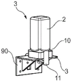
In fig. 5a schematic illustration of a cartridge receptacle 10 and a cartridge system 1 according to a first, second or third embodiment of the present invention inserted into a holding unit 90 of a beverage preparation machine 3 is shown. In fig. 5b a detailed illustration of a holding unit 90 is shown, which essentially consists of a receptacle for the cartridge receptacle 10 and comprises a line for a fluid source 91 extending to the beverage preparation machine 3 for connection to a fluid supply of the cartridge system 1.
Possible embodiments of the inventive cartridge receptacle, the inventive cartridge system, the inventive beverage preparation machine and the inventive method for producing a beverage are described below.
Embodiment 1 relates to a cartridge receptacle 10 for producing a beverage 70 by means of a cartridge 2, comprising a reservoir 6 filled with a beverage substance 7, wherein the cartridge receptacle 10 is insertable into a beverage preparation machine 3 and is connectable to the cartridge 2, wherein the cartridge receptacle 10 has a mixing chamber 8 which is fluidically connectable to the reservoir 6 and a fluid supply 12 which leads into the mixing chamber 8.
Embodiment 2 relates to a cartridge receptacle 10 according to embodiment 1, wherein the cartridge receptacle 10 has cartridge unloading means 34 which are arranged for transferring the beverage substance 7 at least partially from the reservoir 6 into the mixing chamber 8.
Embodiment 3 relates to a cartridge receptacle 10 according to one of the above embodiments, wherein the cartridge receptacle 10 can be fixedly or releasably connected with the cartridge 2 and/or wherein the mixing chamber 8 has a mixing structure in the region of the mouth of the fluid supply 12 leading into the mixing chamber 8.
Embodiment 4 relates to a cartridge receptacle 10 according to one of the above embodiments, wherein the cartridge unloading device 34 comprises a compressed air interface 42 for connection to a compressed air source 41 and a compressed air line 40 which extends from the compressed air interface 42 to a compressed air outlet 43, and wherein the compressed air outlet 43 projects in particular in the direction of the reservoir 6 of the cartridge 2 in order to blow compressed air into the reservoir 6.
Embodiment 5 relates to a cartridge receptacle 10 according to embodiment 4, wherein the cartridge unloading means 34 is configured to press the beverage substance 7 from the reservoir 6 into the mixing chamber 8 by means of the compressed air.
Embodiment 6 relates to a cartridge receptacle 10 according to one of the above embodiments, wherein the mixing chamber 8 has a beverage outflow 11 through which a beverage 70 formed by mixing of the beverage substance 7 with the fluid is discharged, wherein the cartridge receptacle 10 is preferably configured to: so that the beverage 70 can be directly introduced into the portable container from the beverage outflow port 11.
Embodiment 7 relates to a cartridge receptacle 10 according to one of the above embodiments, wherein the cartridge receptacle 10 can be releasably connected to the cartridge 2 by means of a snap connection 50.
Embodiment 8 relates to a cartridge receptacle 10 according to embodiment 7, wherein the cartridge receptacle 10 has resilient latching elements 51 which engage behind retaining flanges 52 formed at the cartridge 2 when the cartridge 2 is fastened in the cartridge receptacle 10.
Embodiment 9 relates to a cartridge receptacle 10 according to one of the above embodiments, wherein the cartridge receptacle 10 is formed substantially in one piece or wherein the cartridge receptacle 10 comprises a cover element 60 and an outlet element 61 connected to the cover element 60.
Embodiment 10 relates to a cartridge receptacle 10 according to embodiment 9, wherein the cover element 60 can be reversibly connected and in particular locked with the cartridge 2 in such a way that a cartridge opening 63 leading to the reservoir 6 is at least temporarily or partially closed by the cover element 60, and wherein the outlet element 61 can be reversibly connected and in particular locked with the cover element 60.
Embodiment 11 relates to a cartridge receptacle 10 according to embodiment 10, wherein the outlet element 61 has the fluid supply 12, the compressed air interface 42, the mixing chamber 8 and/or the beverage flow outlet 11.
Embodiment 12 relates to a cartridge receptacle 10 according to embodiment 9 or 11, wherein the cover element 60 has the compressed air outlet 43, in particular in the form of a hollow tip, which projects in the direction of the reservoir 6 and is in operative connection with a compressed air connection 42 formed on the cover element 60 or on the outlet element 61 via the compressed air line 40.
Embodiment 13 relates to a cartridge receptacle 10 according to one of embodiments 10 to 12, wherein a fluid connection can be made between the cartridge opening 63 and the mixing chamber 8 by means of a valve unit, wherein the valve unit can be transferred from a closed state to an open state by a relative movement between the cover element 60 and the outlet element 61 to form a fluid connection.
Embodiment 14 relates to a cartridge receptacle 10 according to one of embodiments 10 to 13, wherein the cover element 60 has a through opening 62 leading to the cartridge opening 63, wherein the valve unit is formed by the through opening 62 and a projection 64 of the outlet element 61 projecting into the through opening 62, wherein the projection 64 is offset from a position closing the through opening 62 to a position partially releasing the through opening 62 by a relative movement between the cover element 60 and the outlet element 61.
Embodiment 15 relates to a cartridge receptacle 10 according to embodiment 14, wherein the wall of the through opening 62 is provided with at least one lateral channel 65 and wherein the projection 64 is arranged in the region of the at least one lateral channel 65 in a position partially releasing the through opening 62.
Embodiment 16 relates to a cartridge receptacle 10 according to one of embodiments 1 to 9, wherein the cartridge 2 has a cartridge opening 63 in fluid connection with the reservoir 6, wherein the cartridge opening 63 is closed with a sealing element 18, wherein the sealing element 18 has in particular a sealing film which is applied and preferably seals on the edge of the cartridge opening 63.
Embodiment 17 relates to a cartridge receptacle 10 according to embodiment 16, wherein the cartridge receptacle 10 comprises a piercing tip 73 protruding in the direction of the cartridge 2, such that the piercing tip 73 pierces the sealing element 18 and creates a fluid connection between the reservoir 6 and the mixing chamber 8 due to a relative movement between the cartridge receptacle 10 and the cartridge 2.
Embodiment 18 relates to a cartridge receptacle 10 according to embodiment 17, wherein at least one lateral channel 71 is introduced into the wall of the piercing tip 73 when the sealing element 18 is pierced, at least one lateral channel 71 being used for conveying the beverage substance 7 in the direction of the mixing chamber 8.
Embodiment 19 relates to a cartridge receptacle 10 according to one of embodiments 16 to 18, wherein the piercing tip 73 has a through bore in which the compressed air injector 72 is mounted displaceable between a retracted position, in which the compressed air injector 72 does not protrude beyond the piercing tip 73 in the direction of the reservoir 6, and an extended position, in which the compressed air injector 72 protrudes beyond the piercing tip 73 and into the reservoir 6.
Embodiment 20 relates to a cartridge receptacle 10 according to embodiment 19, wherein the compressed air line 40 is integrated into the compressed air injector 72 and wherein the compressed air connection 42 is formed on a side of the compressed air injector 72, in particular remote from the reservoir 6, wherein the compressed air connection 42 is preferably accessible from outside the cartridge receptacle 10.
Embodiment 21 relates to a cartridge receptacle 10 according to one of embodiments 19 or 20, wherein the compressed air injector 72 is transferred by a release element of the beverage preparation machine from the retracted position into the extended position upon insertion of the cartridge system 1 into the beverage preparation machine.
Embodiment 22 relates to a cartridge receptacle 10 according to embodiment 16, wherein the cartridge receptacle 10 comprises a tip guide 80 and a piercing tip 81 displaceably mounted within the tip guide 80, wherein the piercing tip 81 is displaceable between a retracted position, in which the piercing tip 81 is spaced apart from the sealing element 19, and an extended position, in which the piercing tip 81 pierces the sealing element 18 and protrudes into the reservoir 6.
Embodiment 23 relates to a cartridge receptacle 10 according to embodiment 22, wherein when the sealing element 18 is pierced, at least one lateral channel 82 is introduced into the outer wall of the piercing tip 81 for conveying the beverage substance 7 in the direction of the mixing chamber 8.
Embodiment 24 relates to a cartridge receptacle 10 according to one of embodiments 22 or 23, wherein the compressed air line 40 is integrated into the piercing tip 81 and wherein the compressed air connection 42 is formed on a side of the piercing tip 81, in particular remote from the reservoir 6, wherein the compressed air connection 42 is preferably accessible from outside the cartridge receptacle 10.
Embodiment 25 relates to a cartridge receptacle 10 according to one of embodiments 22 to 24, wherein the piercing tip 81 is transferred by a release element of the beverage preparation machine from the retracted position into the extended position upon insertion of the cartridge system 1 into the beverage preparation machine.
Embodiment 26 relates to a cartridge system 1 for producing a beverage 70, wherein the cartridge system 1 can be inserted into a beverage preparation machine 3, wherein the cartridge system 1 has a cartridge 2 and a cartridge receptacle 10 according to one of the above embodiments connected to the cartridge 2, the cartridge comprising a reservoir 6 filled with a beverage substance 7.
Embodiment 27 relates to a cartridge system according to embodiment 26, wherein the cartridge receptacle 10 has a mixing chamber 8, a cartridge unloading device 34 arranged for at least partially transferring the beverage substance 7 from the reservoir 6 into the mixing chamber 8, and a fluid supply 12 leading into the mixing chamber 8.
Embodiment 28 relates to a cartridge system according to embodiment 27, wherein the cartridge 2 is fixedly or releasably connected with the cartridge receptacle 10, wherein the cartridge system 1 is configured to press the beverage substance 7 from the reservoir 6 into the mixing chamber 8 by means of the compressed air.
Embodiment 29 relates to a cartridge system according to one of embodiments 27 or 28, wherein the fluid supply 12 is fed with a fluid which is cooled by a cooling assembly, wherein the cooling assembly is part of the beverage preparation machine or is a separate refrigerator in operative connection with the beverage preparation machine.
Embodiment 30 is directed to the cartridge system of embodiment 29, wherein the cooling assembly comprises a compressor cooling unit, an absorber cooling unit, or a thermoelectric chiller.
Embodiment 31 relates to a cartridge system according to one of embodiments 27 to 30, wherein the fluid supply 12 is fed with a fluid to which carbonic acid is added by a carbonator.
Embodiment 32 relates to a cartridge system according to embodiment 31, wherein the carbonator is part of the beverage preparation machine 3, and wherein the carbonator has a system for CO2Receptacle for a tank and method for removing CO from the tank2Tank adding CO to the fluid2The supply device of (1).
Embodiment 33 relates to a cartridge system according to one of embodiments 27 to 32, wherein the cartridge receptacle 10 is releasably connected to the cartridge 2 by means of a snap connection 50.
Embodiment 34 relates to a cartridge system according to embodiment 33, wherein the cartridge receptacle 10 has resilient latching elements 51 which engage from behind to retaining flanges 52 formed at the cartridge 2 when the cartridge 2 is fastened in the cartridge receptacle 10.
Embodiment 35 relates to a cartridge system according to one of embodiments 26 to 34, wherein the cartridge 2 has a cartridge opening 63 in fluid connection with the reservoir 6, wherein the cartridge opening 63 is closed with a sealing element 18, wherein the sealing element 18 in particular has a sealing film which is applied and preferably seals on the edge of the cartridge opening 63.
Embodiment 36 relates to a cartridge system according to one of embodiments 26 to 35, wherein the cartridge 2 has a further cartridge opening on the side opposite the cartridge opening 63, which further cartridge opening is closed by a further sealing element 10, in particular a further sealing film.
Embodiment 37 relates to a beverage preparation machine 3 for producing a beverage 70, into which a cartridge system 1 according to one of embodiments 26 to 36 can be inserted, wherein the beverage preparation machine 3 has a holding unit 90, into which a cartridge receptacle 10 connected to the cartridge 2 can be inserted, a fluid source 91 for feeding fluid into the fluid supply 12 and a compressed air source 41 for blowing compressed air into the compressed air connection 42.
Embodiment 38 relates to a beverage preparation machine 3 according to embodiment 37, wherein the beverage preparation machine 3 has the release element in order to transfer the compressed air injector 72 or the piercing tip 81 from the retracted position into the extended position.
Embodiment 39 relates to a method for producing a beverage 70, in particular using a cartridge system 1 according to one of embodiments 26 to 36, having the following steps:
the cartridge system 1 is inserted into the holding unit 90 of the beverage preparation machine 3,
the beverage substance 7 is transferred from the reservoir 6 of the cartridge 2 into the mixing chamber 8 of the cartridge receptacle 10 by means of the cartridge unloading means 34,
the mixing chamber 8 is fed with fluid by means of the fluid supply 12,
the beverage 70 produced in the mixing chamber 8 by mixing the beverage substance 7 with the fluid is conducted out by means of the beverage outflow opening 11.
Embodiment 40 relates to a method according to embodiment 39, wherein the beverage substance 7 is transferred from the reservoir 6 into the mixing chamber 8 by compressed air.
Embodiment 41 relates to a method according to one of embodiments 39 or 40, wherein the fluid is cooled and/or carbonated before being fed into the mixing chamber 8.
Embodiment 42 relates to a method according to one of embodiments 39 to 41, wherein before, during or after inserting the cartridge system 1 into the holding unit 90, the compressed air injector 72 or the piercing tip 81 is transferred from the retracted position into the extended position and the sealing element 18 at the cartridge opening 63 is perforated.
Embodiment 43 relates to a method according to one of embodiments 39 to 42, wherein a fluid connection between the reservoir 6 and the mixing chamber 8 is formed by relative movement between a cover element 60 and an outlet element 61 causing opening of a valve unit before, during or after insertion of the cartridge system 1 into the holding unit 90.
List of reference numerals
1-box system
2 case
3 beverage preparation machine
6 storage container
7 beverage substance
8 mixing chamber
10-box receiving seat
11 beverage outflow opening
12 fluid supply
18 sealing element
19 additional sealing element
34 box unloading device
40 compressed air line
41 compressed air source
42 compressed air interface
43 compressed air outlet
50 snap-lock connector
51 latching element
52 holding flange
60 cover element
61 outlet element
62 through opening
63 box opening
64 convex
65, 71, 82 lateral passages
70 beverage
71 lateral channel
72 compressed air injector
73 piercing tip
80 tip guide
81 piercing point
82 lateral channel
90 holding unit
91 fluid source.