KR20150070242A - Card for containing food or beverage ingredients - Google Patents
Card for containing food or beverage ingredients Download PDFInfo
- Publication number
- KR20150070242A KR20150070242A KR1020157012097A KR20157012097A KR20150070242A KR 20150070242 A KR20150070242 A KR 20150070242A KR 1020157012097 A KR1020157012097 A KR 1020157012097A KR 20157012097 A KR20157012097 A KR 20157012097A KR 20150070242 A KR20150070242 A KR 20150070242A
- Authority
- KR
- South Korea
- Prior art keywords
- card
- food
- compartments
- beverage
- outlet
- Prior art date
- Legal status (The legal status is an assumption and is not a legal conclusion. Google has not performed a legal analysis and makes no representation as to the accuracy of the status listed.)
- Withdrawn
Links
Images


Classifications
-
- B—PERFORMING OPERATIONS; TRANSPORTING
- B65—CONVEYING; PACKING; STORING; HANDLING THIN OR FILAMENTARY MATERIAL
- B65D—CONTAINERS FOR STORAGE OR TRANSPORT OF ARTICLES OR MATERIALS, e.g. BAGS, BARRELS, BOTTLES, BOXES, CANS, CARTONS, CRATES, DRUMS, JARS, TANKS, HOPPERS, FORWARDING CONTAINERS; ACCESSORIES, CLOSURES, OR FITTINGS THEREFOR; PACKAGING ELEMENTS; PACKAGES
- B65D85/00—Containers, packaging elements or packages, specially adapted for particular articles or materials
- B65D85/70—Containers, packaging elements or packages, specially adapted for particular articles or materials for materials not otherwise provided for
- B65D85/804—Disposable containers or packages with contents which are mixed, infused or dissolved in situ, i.e. without having been previously removed from the package
- B65D85/8043—Packages adapted to allow liquid to pass through the contents
- B65D85/8055—Means for influencing the liquid flow inside the package
-
- B—PERFORMING OPERATIONS; TRANSPORTING
- B65—CONVEYING; PACKING; STORING; HANDLING THIN OR FILAMENTARY MATERIAL
- B65D—CONTAINERS FOR STORAGE OR TRANSPORT OF ARTICLES OR MATERIALS, e.g. BAGS, BARRELS, BOTTLES, BOXES, CANS, CARTONS, CRATES, DRUMS, JARS, TANKS, HOPPERS, FORWARDING CONTAINERS; ACCESSORIES, CLOSURES, OR FITTINGS THEREFOR; PACKAGING ELEMENTS; PACKAGES
- B65D85/00—Containers, packaging elements or packages, specially adapted for particular articles or materials
- B65D85/70—Containers, packaging elements or packages, specially adapted for particular articles or materials for materials not otherwise provided for
- B65D85/804—Disposable containers or packages with contents which are mixed, infused or dissolved in situ, i.e. without having been previously removed from the package
- B65D85/8043—Packages adapted to allow liquid to pass through the contents
-
- A—HUMAN NECESSITIES
- A47—FURNITURE; DOMESTIC ARTICLES OR APPLIANCES; COFFEE MILLS; SPICE MILLS; SUCTION CLEANERS IN GENERAL
- A47J—KITCHEN EQUIPMENT; COFFEE MILLS; SPICE MILLS; APPARATUS FOR MAKING BEVERAGES
- A47J31/00—Apparatus for making beverages
- A47J31/40—Beverage-making apparatus with dispensing means for adding a measured quantity of ingredients, e.g. coffee, water, sugar, cocoa, milk, tea
- A47J31/407—Beverage-making apparatus with dispensing means for adding a measured quantity of ingredients, e.g. coffee, water, sugar, cocoa, milk, tea with ingredient-containing cartridges; Cartridge-perforating means
-
- B—PERFORMING OPERATIONS; TRANSPORTING
- B65—CONVEYING; PACKING; STORING; HANDLING THIN OR FILAMENTARY MATERIAL
- B65D—CONTAINERS FOR STORAGE OR TRANSPORT OF ARTICLES OR MATERIALS, e.g. BAGS, BARRELS, BOTTLES, BOXES, CANS, CARTONS, CRATES, DRUMS, JARS, TANKS, HOPPERS, FORWARDING CONTAINERS; ACCESSORIES, CLOSURES, OR FITTINGS THEREFOR; PACKAGING ELEMENTS; PACKAGES
- B65D81/00—Containers, packaging elements, or packages, for contents presenting particular transport or storage problems, or adapted to be used for non-packaging purposes after removal of contents
- B65D81/32—Containers, packaging elements, or packages, for contents presenting particular transport or storage problems, or adapted to be used for non-packaging purposes after removal of contents for packaging two or more different materials which must be maintained separate prior to use in admixture
- B65D81/3294—Thermoformed trays or the like with a plurality of recesses for different materials located in different recesses
-
- B—PERFORMING OPERATIONS; TRANSPORTING
- B65—CONVEYING; PACKING; STORING; HANDLING THIN OR FILAMENTARY MATERIAL
- B65D—CONTAINERS FOR STORAGE OR TRANSPORT OF ARTICLES OR MATERIALS, e.g. BAGS, BARRELS, BOTTLES, BOXES, CANS, CARTONS, CRATES, DRUMS, JARS, TANKS, HOPPERS, FORWARDING CONTAINERS; ACCESSORIES, CLOSURES, OR FITTINGS THEREFOR; PACKAGING ELEMENTS; PACKAGES
- B65D85/00—Containers, packaging elements or packages, specially adapted for particular articles or materials
- B65D85/70—Containers, packaging elements or packages, specially adapted for particular articles or materials for materials not otherwise provided for
- B65D85/804—Disposable containers or packages with contents which are mixed, infused or dissolved in situ, i.e. without having been previously removed from the package
- B65D85/8043—Packages adapted to allow liquid to pass through the contents
- B65D85/8046—Pods, i.e. closed containers made only of filter paper or similar material
-
- B—PERFORMING OPERATIONS; TRANSPORTING
- B65—CONVEYING; PACKING; STORING; HANDLING THIN OR FILAMENTARY MATERIAL
- B65D—CONTAINERS FOR STORAGE OR TRANSPORT OF ARTICLES OR MATERIALS, e.g. BAGS, BARRELS, BOTTLES, BOXES, CANS, CARTONS, CRATES, DRUMS, JARS, TANKS, HOPPERS, FORWARDING CONTAINERS; ACCESSORIES, CLOSURES, OR FITTINGS THEREFOR; PACKAGING ELEMENTS; PACKAGES
- B65D85/00—Containers, packaging elements or packages, specially adapted for particular articles or materials
- B65D85/70—Containers, packaging elements or packages, specially adapted for particular articles or materials for materials not otherwise provided for
- B65D85/804—Disposable containers or packages with contents which are mixed, infused or dissolved in situ, i.e. without having been previously removed from the package
- B65D85/8043—Packages adapted to allow liquid to pass through the contents
- B65D85/8058—Coding means for the contents
-
- B—PERFORMING OPERATIONS; TRANSPORTING
- B65—CONVEYING; PACKING; STORING; HANDLING THIN OR FILAMENTARY MATERIAL
- B65D—CONTAINERS FOR STORAGE OR TRANSPORT OF ARTICLES OR MATERIALS, e.g. BAGS, BARRELS, BOTTLES, BOXES, CANS, CARTONS, CRATES, DRUMS, JARS, TANKS, HOPPERS, FORWARDING CONTAINERS; ACCESSORIES, CLOSURES, OR FITTINGS THEREFOR; PACKAGING ELEMENTS; PACKAGES
- B65D85/00—Containers, packaging elements or packages, specially adapted for particular articles or materials
- B65D85/70—Containers, packaging elements or packages, specially adapted for particular articles or materials for materials not otherwise provided for
- B65D85/804—Disposable containers or packages with contents which are mixed, infused or dissolved in situ, i.e. without having been previously removed from the package
- B65D85/8043—Packages adapted to allow liquid to pass through the contents
- B65D85/8067—Packages for several ingredients
Landscapes
- Engineering & Computer Science (AREA)
- Mechanical Engineering (AREA)
- Food Science & Technology (AREA)
- Apparatus For Making Beverages (AREA)
- Packging For Living Organisms, Food Or Medicinal Products That Are Sensitive To Environmental Conditiond (AREA)
- Packages (AREA)
- Package Specialized In Special Use (AREA)
- Tea And Coffee (AREA)
- General Preparation And Processing Of Foods (AREA)
Abstract
본 발명은 식품 또는 음료 성분들을 담기 위한 카드에 관한 것으로, 상기 카드는 실질적으로 평면의 강성 베이스부, 상기 성분들을 저장하기 위한 적어도 2 개의 성분 격실들 및 적어도 2 개의 배출부들로서, 각각의 배출부는 상기 격실들 중 하나에 링크되고 상기 베이스부의 평면을 따라 연장되는, 적어도 2 개의 성분 격실들 및 적어도 2 개의 배출부들, 및 상기 카드의 베이스부 측에서 격실들 및 배출부들을 덮는 상기 베이스부에 제공된 적어도 하나의 실링 부재를 포함하고, 상기 카드는 상기 격실들로부터 상기 배출부들을 통하여 상기 성분들을 디스펜싱하기 위해서 식품 및 음료 제조 기기에 삽입하도록 설계된다. 본 발명은 또한 본 발명에 따른 카드와 식품 및 음료 제조 기기를 포함하는 식품 및 음료 제조 시스템뿐만 아니라 카드를 이용한 식품 또는 음료들을 제조하기 위한 방법에 관한 것이다.The present invention relates to a card for containing food or beverage ingredients, said card comprising a substantially planar rigid base portion, at least two ingredient compartments for storing said ingredients and at least two outlets, At least two component compartments and at least two discharge ports linked to one of the compartments and extending along a plane of the base portion and a plurality of compartments provided in the base portion covering the compartments and discharge portions at the base portion side of the card And at least one sealing member, the card being designed to be inserted into the food and beverage making appliance for dispensing the components from the compartments through the outlets. The present invention also relates to a food and beverage production system comprising a card and a food and beverage production device according to the present invention, as well as a method for producing food or beverage using the card.
Description
본 발명은 식품 또는 음료 성분들을 담기 위한 카드 또는 카트리지, 본 발명에 따른 카드와 식품 및 음료 제조 기기를 포함하는 식품 및 음료 제조 시스템, 및 카드를 이용한 식품 또는 음료들을 제조하기 위한 방법에 관한 것이다.The present invention relates to a card or cartridge for containing food or beverage ingredients, a food and beverage manufacturing system comprising a card and a food and beverage manufacturing device according to the invention, and a method for producing food or beverages using the card.
디스펜싱될 제품을 위한 성분들을 담고 있는 캡슐을 사용함으로써 식품 또는 커피와 같은 음료를 제조하는 것은 잘 알려져 있다. 도 12 에서, 음료 성분들을 담은 캡슐 보디 (201) 를 가지는 캡슐 (200) 이 나타나 있다. 캡슐 (200) 은 제 1 막 (202) 및 제 2 막 (203) 에 의해 폐쇄되어 있다. 음료를 제조하기 위해, 대응하는 음료 제조 기기의 물 주입 니들 (210) 은 제 1 막 (202) 을 통하여 캡슐 (200) 로 삽입되고 물은 용해 단계에서 음료 성분과 상호작용하도록 캡슐 (200) 내부에 주입된다. 주입될 때, 물은 과압을 형성하여 제 2 막 (203) 이 파열면 (예컨대, 피라미드 플레이트) 에 대해 개방하도록 유발하여서 음료 (즉 제품) 는 화살표 (220) 로 나타낸 바와 같은 이송 단계에서 캡슐 (200) 로부터 디스펜싱될 수 있다.It is well known to produce beverages such as food or coffee by using capsules containing ingredients for the product to be dispensed. 12, a
일단 물이 캡슐 (200) 내부에 주입되고 나면, 음료 제조를 중단하거나 그렇지 않으면 용해 단계 또는 이송 단계에 영향을 미치는 것이 가능하지 않다. 더욱이, - 다층 음료와 같은 - 복잡한 음료들을 제조할 때, 음료 제조를 위해 여러 개의 캡슐들이 필요하고, 각각의 캡슐은 음료의 (특정한 층을 위한) 다른 성분을 포함한다.Once the water is injected into the
본 발명은 전술한 단점들을 개선하는 것을 목표로 하고, 본 발명의 목적은, 용이하고 경제적인 방식으로 복잡한 (예컨대 1 회분씩 분배되거나 (portioned) 다층인) 음료들 또는 식품의 유연한 제조를 허용하는, 식품 또는 음료 성분들을 담기 위한 카드, 식품 및 음료 제조 시스템, 및 식품 또는 음료를 제조하기 위한 방법을 제공하는 것이다.The present invention aims at improving the above-mentioned disadvantages, and it is an object of the present invention to provide a process for the production of beverages or foods which allow complicated (for example, , A card for containing food or beverage ingredients, a food and beverage manufacturing system, and a method for manufacturing food or beverage.
상기 목적은 독립항들에 의해 달성될 것이다. 종속항들은 유리하게도 본 발명의 중심 사상을 추가로 검토한다.The above object will be achieved by the independent claims. The dependent claims advantageously further consider the central idea of the present invention.
본 발명의 제 1 양태에 따르면, 청구항 1 에 따른 식품 또는 음료 성분들을 담기 위한 카드가 제공된다.According to a first aspect of the present invention, there is provided a card for containing food or beverage ingredients according to
카드는 평면의 강성 베이스부, 식품 또는 음료 성분들을 저장하기 위한 적어도 2 개의 격실들 및 각각의 격실로부터 베이스부의 평면을 따라 연장되는 배출부 (예컨대, 채널) 를 포함하고, 적어도 하나의 실링 부재 (예컨대 포일 부재 또는 막) 는 모든 격실들과 배출부들을 덮도록 베이스부에 제공되어서, 카드의 베이스부 측에서 격실들과 배출부들의 개구들을 완전히 한정한다. 하나의 실링 부재가 모든 개구들을 덮지만, 제조 필요 (별도의 충전 라인들 등) 에 따라, 개별 격실들이 개별 시일들에 의해 폐쇄될 수 있다. 카드는 격실들로부터 배출부들을 통하여 성분들을 디스펜싱하기 위해서 식품 및 음료 제조 기기에 삽입하도록 설계된다.The card includes a rigid base portion of planar, at least two compartments for storing food or beverage ingredients, and a discharge (e.g., channel) extending along the plane of the base portion from each compartment, and at least one sealing member Such as a foil member or membrane, is provided in the base portion to cover all of the compartments and outlets, thereby completely defining the openings in the compartments and outlets at the base portion side of the card. One sealing member covers all of the openings, but according to the manufacturing need (separate charging lines, etc.), the individual compartments can be closed by separate seals. The card is designed to be inserted into food and beverage making equipment to dispense components from the compartments through the discharge ports.
격실들 및 배출부들 양자는 베이스부의 평면으로부터 (바람직하게 동일한 방향으로) 돌출한 리세스들에 의해 형성된다. 용어 "리세스" 는 베이스부로부터 튀어나온 돌출 보디로서 이해되어야 하고, 상기 돌출부는 베이스부를 통하여 (내부의 개구를 통하여) 접근가능하고 베이스부에 제공된 실링 부재로 덮여질 때 중공 부재 또는 캐비티를 형성한다.Both the compartments and the discharge portions are formed by recesses projecting from the plane of the base portion (preferably in the same direction). The term "recess" should be understood as a protruding body protruding from the base portion, said protrusion being accessible through the base portion (through an internal opening) and forming a hollow member or cavity when covered with a sealing member provided in the base portion do.
바람직하게, 성분들과 혼합될 액체는 베이스부 측에서 카드로 주입되고, 최종 제품은 베이스부에 대해 대략 90°의 각도를 형성하는 측방향 측에서 디스펜싱되고, 즉 카드를 이탈한다. 도 12 에 도시된 것과 같은 통상적인 시스템들에서, 유동은 캡슐을 통하여 직선으로 진행하고, 즉 액체 주입부와 디스펜싱 출구 사이 각도는 약 180° 이어서, 최적의 용해 및 혼합을 얻도록 격실 또는 캡슐의 내부에서 충분한 난류 (turbulent currents) 의 형성을 허용하지 않는다. Preferably, the liquid to be mixed with the components is injected into the card at the side of the base portion, and the final product is dispensed at the lateral side forming an angle of about 90 with respect to the base portion, i. 12, the flow proceeds straight through the capsule, that is, the angle between the liquid injection portion and the dispensing outlet is about 180 [deg.] So that the compartment or capsule Lt; RTI ID = 0.0 > turbulent < / RTI > currents.
하지만, 격실들에 들어있는 성분들은 카드 밖으로 곧장, 다시 말해서, 상기 격실들 내에서 기계로부터 주입된 액체와 혼합되지 않고 디스펜싱될 수 있다. 이러한 경우에, 식품 또는 음료 제품은, 성분들이 (컵과 같은 수용 컨테이너 내부에서) 카드로부터 방출될 때 격실들 내부에 들어있는 성분들을 혼합함으로써, 또는 대안적으로, 카드의 혼합 챔버 내에서 성분들을 혼합함으로써 형성되고, 이렇게 형성된 식품 또는 음료 제품은 최종적으로 혼합 챔버로부터 수용 컨테이너 (예로, 컵 또는 보울 또는 유사한 컨테이너) 를 향해 디스펜싱된다. 그 경우에, 카드에 들어있는 성분들이 내부에 주입된 혼합 유체와 혼합되지 않을 때, 기계는 바람직하게 실링 부재를 관통하고 카드 내부에 가스와 같은 추진 매체를 주입하여서 카드의 외부로 격실들에 들어있는 성분들을 방출한다. However, the components contained in the compartments may be dispensed straight out of the card, i. E., Without mixing with the liquid injected from the machine in the compartments. In such a case, the food or beverage product may be dispensed by mixing the ingredients contained within the compartments as they are discharged from the card (within a receptacle container such as a cup) or, alternatively, And the food or beverage product thus formed is finally dispensed from the mixing chamber toward the receiving container (e.g., cup or bowl or similar container). In that case, when the ingredients contained in the card are not mixed with the mixed fluid injected into the machine, the machine preferably penetrates the sealing member and injects propulsion media, such as gas, into the card to enter the compartments outside of the card Releases the components that are present.
또한, 식품 또는 음료 제조 기계가 카드의 외부로 격실들에 들어있는 성분들을 디스펜싱할 수 있도록 허용하는 디스펜싱 수단이 이하 설명된다.Dispensing means that allow the food or beverage making machine to dispense components contained in the compartments to the outside of the card are also described below.
본 발명의 바람직한 실시형태에 따르면, 식품 또는 음료 성분들을 담기 위한 카드는 음료, 수프 또는 다른 식품 제품을 제조하기 위한 기기에 사용될 캡슐 또는 카트리지이다.According to a preferred embodiment of the present invention, the card for containing food or beverage ingredients is a capsule or cartridge to be used in a device for making a beverage, soup or other food product.
카드가 복수의 격실들을 포함함에 따라, 단순히 하나의 단일 캡슐을 사용함으로써 복잡한 음료 또는 식품 제품을 제조할 수 있고, 각각의 격실은 상기 복잡한 제품에 대한 다른 성분을 홀딩할 수 있다. 이것은, 예컨대 용해 또는 적어도 디스펜싱을 위해 격실들에 차례로 유체 (예로, 물 또는 우유) 를 주입함으로써 각각의 격실들이 선택적으로 프로세싱될 수 있다는 사실에 기인한 것이다. 또한, 하나의 격실로부터, 그 후 제 2 격실로부터, 그 후 다시 제 1 격실로부터 제품의 제 1 부분들을 디스펜싱할 수 있지만, 그것은 다른 성분들을 위한 다른 캡슐들이 사용될 때는 거의 불가능하다. 따라서, 각각의 격실들에서 용해 및 디스펜싱이 개별적으로 수행되고 영향을 미칠 수 있으므로, 식품 또는 음료 제조는 매우 유연한 방식으로 수행될 수 있다. 따라서, 본 발명은 다층 수프, 디저트류 또는 뜨겁거나 차가운 음료와 같은 레이어드 (layered) 제품들의 제조를 허용한다. 모든 격실들 및 배출부들은 카드의 베이스부 측에서 완전히 덮여있으므로, 복수의 격실들을 실링하거나 적어도 폐쇄하는데 단 하나의 실링 부재만 필요하므로 카드의 제조가 용이하게 된다. 이것은 복잡한 제품들을 위해 여러 캡슐들을 사용하는 시스템과 비교해 다른 장점이다.As the card includes a plurality of compartments, a complex beverage or food product can be made by simply using a single capsule, and each compartment can hold other components for the complex product. This is due to the fact that each compartment can be selectively processed by, for example, injecting a fluid (e.g., water or milk) in turn into the compartments for dissolving or at least dispensing. It is also possible to dispense the first parts of the product from one compartment, then from the second compartment, and then again from the first compartment, but it is almost impossible when other capsules for the other components are used. Thus, the dissolution and dispensing in each of the compartments can be individually effected and effected, so that food or beverage production can be performed in a very flexible manner. Thus, the present invention allows the production of multi-layered soups, desserts or layered products such as hot or cold beverages. Since all of the compartments and discharges are completely covered at the base portion side of the card, the card is easily manufactured since only one sealing member is required to seal or at least close the plurality of compartments. This is another advantage compared to systems that use multiple capsules for complex products.
본 발명의 바람직한 실시형태에 따르면, 카드의 배출부들의 적어도 일부는 각각의 격실로부터 공통 혼합 챔버로 연장되고 이 공통 혼합 챔버로부터 추가 배출부 (예컨대, 혼합 채널) 가 베이스부의 평면을 따라 연장된다. 카드로 주입되는 액체와 성분의 혼합은 디스펜싱 전 격실들 그 자체에서 일어날 수 있지만, 부가적 혼합 챔버는 부가적 (또는 대안적) 혼합 또는 용해 단계를 허용하고, 이 단계에서 특정 격실들의 성분들은 디스펜싱되기 전 혼합 챔버에서 액체와 선택적으로 혼합될 수 있어서, 복잡한 시스템의 기능성을 단일 캡슐로 통합한다. 하나의 격실로부터 단 하나의 성분을 액체와 혼합할 수 있고 또는 다른 격실들로부터 여러 성분들을 액체와 혼합할 수 있다. 원칙적으로 또한 다른 액체들을 카드로 도입할 수 있고 다른 액체들을 혼합 챔버에서 하나 이상의 성분과 혼합할 수 있다. 혼합 챔버와 혼합 채널 양자는, 카드의 격실들 및 배출부들과 베이스부의 평면으로부터 동일한 방향으로 돌출한 리세스들에 의해 형성될 수 있다. 바람직하게, 혼합 채널은 혼합 챔버로부터 베이스부의 측방향 단부 구역까지 연장되어서 카드의 출구를 형성한다.According to a preferred embodiment of the invention, at least a portion of the ejection portions of the card extend from the respective compartment to the common mixing chamber and an additional outlet (e.g., mixing channel) extends from the common mixing chamber along the plane of the base portion. Mixing of the liquid and components injected into the card can occur in the compartments before dispensing itself, but the additional mixing chamber allows an additional (or alternative) mixing or dissolving step in which the components of certain compartments Can be selectively mixed with the liquid in the mixing chamber prior to dispensing, thereby integrating the functionality of the complex system into a single capsule. One component from the one compartment can be mixed with the liquid or the other components can be mixed with the liquid from the other compartments. In principle, other liquids may also be introduced into the card and other liquids may be mixed with one or more components in the mixing chamber. Both the mixing chamber and the mixing channel can be formed by the recesses projecting in the same direction from the plane of the base portion and the compartments and discharge portions of the card. Preferably, the mixing channel extends from the mixing chamber to the lateral end region of the base portion to form an outlet of the card.
각각의 격실 또는 혼합 챔버는 그 자체의 배출부 또는 그로부터 연장되는 채널에 링크되므로, 다른 성분들의 디스펜싱 타이밍 및 순서를 제어할 수 있다. 이러한 제어를 허용하기 위해서, 배출부들 중 적어도 하나와 상호작용하는 적어도 하나의 프로세싱 부재가 제공될 수 있다. 예를 들어 프로세싱 부재는 배출부들 중 하나에, 또는 예를 들어 혼합 챔버에서 배출부 옆에 위치될 수 있다. 본 발명의 바람직한 실시형태에 따르면, 하나의 프로세싱 부재는 각각의 격실 및 격실에 링크된 배출부와 연관된다.Each compartment or mixing chamber is linked to its own discharge or channel extending therefrom, so that dispensing timing and order of the other components can be controlled. To allow for such control, at least one processing element may be provided that interacts with at least one of the outlets. For example, the processing member may be located at one of the outlets, or at the exit of the mixing chamber, for example. According to a preferred embodiment of the present invention, one processing element is associated with each compartment and with a discharge linked to the compartment.
프로세싱 부재는 카드의 중공부에, 바람직하게 배출부들 또는 채널들 중 적어도 하나에 배열되는 정적 혼합기일 수 있다. 이러한 정적 혼합기는 디스펜싱될 성분들의 충분한 혼합을 허용하고, 동시에 또한, 특히 부가적으로 가스 (예컨대 공기) 가 각각의 배출부로 주입될 때, 바람직하게 정적 혼합기의 상류에서 발포 제품을 형성하도록 허용한다.The processing member may be a static mixer arranged in the hollow portion of the card, preferably in at least one of the outlets or channels. This static mixer allows for sufficient mixing of the components to be dispensed and at the same time, and additionally permits to form a foamed product, preferably upstream of the static mixer, additionally when a gas (for example air) is injected into each discharge .
본 발명의 바람직한 실시형태에 따르면, 카드는 적어도 하나의 배출부에 배열되고 내부에서 움직일 수 있는 적어도 하나의 유동 프로세싱 요소를 포함한다. 유동 프로세싱 요소는 예를 들어 배출부를 막도록 배출부에 배열된 밸브 또는 단순 플러그형 요소일 수 있다. 바람직하게, 유동 제어 요소는, 성분들 (이와 같거나 주입된 액체에 이미 혼합되거나 용해된 것) 이 배출부들을 통과할 수 있도록 허용하는 채널들을 포함한다. 채널들은 유동 프로세싱 요소의 표면, 또는 내부에 형성될 수 있다. 추가 바람직한 실시형태에 따르면, 유동 프로세싱 요소는 배출부의 입구 또는 출구를 폐쇄하는 폐쇄 수단을 관통하기 위한 관통 부재를 포함한다. 예를 들어, 격실들은 폐쇄 수단에 의해 배출부들로부터 분리될 수 있고, 폐쇄 수단은, 격실의 내용물이 디스펜싱되거나 혼합 챔버로 안내될 때 관통 부재에 의해 관통된다. 관통하여 디스펜싱 또는 추가 혼합을 개시하기 위해서, 유동 제어 요소는 배출부를 따라 이동된다. 유동 제어 요소는 예를 들어 카드의 베이스부를 덮는 실링 부재를 통하여 돌출한 작동 부재에 의해 배출부들을 따라 이동될 수 있다. 배출부들은 바람직하게 각각의 격실 또는 혼합 챔버로부터 베이스부의 측방향 단부 구역을 향해 연장되어서 카드의 출구를 형성한다. 카드의 출구는 격실들을 덮는 실링 부재와 일체로 형성되는 시일에 의해 실링될 수 있고, 예를 들어 상기 출구를 덮기 위해서 대략 90°의 각도로 단순히 구부러지는 하나의 포일 또는 시트가 사용될 수 있다.According to a preferred embodiment of the invention, the card comprises at least one flow processing element arranged in at least one discharge and movable inside. The flow processing element may be, for example, a valve or a simple plug-type element arranged in the discharge portion to block the discharge portion. Preferably, the flow control element includes channels that allow components (such as are already mixed or dissolved with the injected liquid) to pass through the outlets. The channels may be formed on the surface, or inside the flow processing element. According to a further preferred embodiment, the flow processing element comprises a penetrating member for penetrating the closing means closing the inlet or outlet of the discharge. For example, the compartments may be separated from the discharge portions by a closure means, and the closure means are pierced by the penetrating member when the contents of the compartment are dispensed or guided to the mixing chamber. To initiate dispensing or further mixing through, the flow control element is moved along the outlet. The flow control element can be moved along the discharge portions by, for example, an actuating member projecting through a sealing member covering the base portion of the card. The discharge portions preferably extend from the respective compartment or mixing chamber toward the lateral end regions of the base portion to form an outlet of the card. The outlet of the card may be sealed by a seal integrally formed with the sealing member covering the compartments, for example, a single foil or sheet may be used which simply bends at an angle of approximately 90 degrees to cover the outlet.
카드가 혼합 챔버를 포함할 때, 유동 제어 요소는, 카드의 대응하는 배출부로부터 각각의 격실을 실링하는 폐쇄 수단을 향하여 카드의 배출부들의 적어도 하나 또는 여러 개로 연장되는 제 1 관통 부재들을 가지는 상기 혼합 챔버에 제공될 수 있다. 유동 제어 요소는, 추가 배출부의 입구 또는 출구를 실링하는 폐쇄 수단을 향해 혼합 챔버의 하류의 이 추가 배출부로 연장되는 제 2 관통 부재를 추가로 포함할 수 있다. 유동 제어 요소는 그로부터 실링 부재를 통하여 돌출한 작동 부재를 포함할 수 있어서 카드의 배출부들 또는 채널들로부터 격실들을 실링하는 적어도 하나, 바람직하게 모든 폐쇄 요소들이, 베이스부의 평면을 따라 제 1 방향으로 유동 제어 요소를 이동시킬 때, 제 1 관통 부재들에 의해 관통될 수 있고, 추가 배출부의 입구 또는 출구를 실링하는 폐쇄 요소는 베이스부의 평면을 따라 제 2 방향으로 유동 제어 요소를 이동시킴으로써 관통될 수 있다. 바람직하게 제 1 방향 및 제 2 방향은 서로 반대이다. 따라서, 반대 방향으로 관통 부재의 변위는 추가 배출부 (즉 혼합 채널) 를 폐쇄하는 실링부를 관통함으로써 카드, 바람직하게 혼합 챔버를 개방시키면서, 하나의 단일 단계로 하나의 유동 제어 요소를 변위시킴으로써 복수의 격실들을 개방할 수 있다. 또한, 전술한 제 1 및 제 2 방향보다 많은 방향으로 유동 제어 요소가 이동될 수 있는 가능성이 있고, 각각의 방향들 중 각각에서 단 하나 또는 미리 규정된 개수의 실링부들이 관통되어 각각의 배출부들 또는 채널들을 개방한다.When the card comprises a mixing chamber, the flow control element has first penetrating members extending from at least one or more of the discharge portions of the card toward the closing means sealing the respective compartment from the corresponding discharge portion of the card, May be provided in the mixing chamber. The flow control element may further comprise a second penetrating member extending to this further outlet downstream of the mixing chamber towards the closure means sealing the inlet or outlet of the further outlet. The flow control element may comprise an actuating member projecting therefrom through the sealing member so that at least one, preferably all, of the closing elements sealing the compartments from the discharge or channels of the card are moved in a first direction along the plane of the base part When moving the control element, the closing element, which may be pierced by the first penetrating members and sealing the inlet or outlet of the further outlet, may be pierced by moving the flow control element in the second direction along the plane of the base part . Preferably, the first direction and the second direction are opposite to each other. Thus, displacement of the penetrating element in the opposite direction penetrates the sealing portion closing the additional discharge (i. E., The mixing channel) thereby displacing one flow control element in one single step, preferably opening the mixing chamber, The compartments can be opened. There is also the possibility that the flow control element can be moved in more directions than the first and second directions described above and that only one or a predefined number of sealing portions in each of the respective directions are penetrated, Or channels.
격실들, 혼합 챔버 및 배출부들은 바람직하게 베이스부와 일체로 형성된다. 그러므로, 카드는 용이하고 경제적인 방식으로 제조될 수 있다. 또한, 격실들 및/또는 혼합 챔버 중 적어도 하나는 실링 부재에 의해 덮여있는 베이스부 내 개구 둘레에 제공 (바람직하게 실링) 되는, 포일 부재와 같은, 연성 또는 가요성 재료로 만들어지고; 포일 부재에 의해 경계가 정해진 공간으로 통과하는 베이스부 내 개구는 리세스, 즉 격실 또는 혼합 챔버를 형성하는 것이 가능하다. 강성 격실들/혼합 챔버 대신에 가요성 격실들/혼합 챔버를 사용함으로써, 각각의 격실들에 저장되거나 각각의 혼합 챔버에서 혼합되는 식품 또는 음료 성분들은, (기계적 푸시) 액추에이터에 의해 각각의 격실들/혼합 챔버를 플래트닝 (flatten) 하거나 크러시 (crush) 함으로써 상기 리세스 밖으로 용이하게 프레스되거나 짜낼 수 있다. 식품 또는 음료 성분들을 디스펜싱하는데 기계적 힘을 사용함으로써, 다른 공지된 표준 원리들; 예컨대 매우 점성이 있는 성분들을 사용할 때 디스펜싱될 수 없는 성분들을 카드 또는 카트리지 내에 제공하는 것이 또한 가능하다. 선택적으로, 배출부들은 각각의 배출 수단을 통하여 유체 유동을 제어하기 위해서 식품 및 음료 제조 기기의 클램핑 수단에 의해 클램핑될 클램핑부를 포함할 수 있다. 배출 수단은 카드에 형성된 채널들, 카드와 조립된 별도의 요소에 형성된 채널, 또는 카드에 형성된 채널들 또는 리세스들에 링크된 가요성 또는 강성 튜브일 수 있다.The compartments, the mixing chamber and the discharge portions are preferably formed integrally with the base portion. Therefore, the card can be manufactured in an easy and economical manner. Also, at least one of the compartments and / or the mixing chamber is made of a soft or flexible material, such as a foil member, provided (preferably sealed) around an opening in the base portion covered by the sealing member; The opening in the base portion through which it passes into the space delimited by the foil member is possible to form a recess, i. E. A compartment or mixing chamber. By using flexible compartments / mixing chambers instead of rigid compartments / mixing chambers, the food or beverage ingredients stored in each compartment or mixed in each mixing chamber can be separated by a (mechanical push) / The mixing chamber can be easily pressed or squeezed out of the recess by flattening or crushing it. By using mechanical forces to dispense food or beverage ingredients, other known standard principles; It is also possible, for example, to provide components in the card or cartridge that can not be dispensed when using very viscous components. Optionally, the discharge portions may include a clamping portion to be clamped by the clamping means of the food and beverage manufacturing equipment to control fluid flow through the respective discharge means. The discharging means can be a channel formed in the card, a channel formed in a separate element assembled with the card, or a flexible or rigid tube linked to channels or recesses formed in the card.
예를 들어, 카드의 배출부들이 베이스부로부터, 바람직하게 베이스부의 측방향 단부 구역으로부터 연장되는 디스펜싱 부재의 (바람직하게 가요성) 채널들을 통과하는 것이 가능하다. 채널들은 바람직하게 튜브들에 의해 형성된다. 하지만, 또한, 채널들은 디스펜싱 부재의 베이스부의 평면으로부터 동일한 방향으로 돌출한 리세스들에 의해 형성되는 것이 가능하고, 이 리세스들은 그 후 베이스부에 제공된 실링 부재로 덮여있어서 디스펜싱 부재의 베이스부 측에서 채널들을 완전히 한정한다. 상기 디스펜싱 부재에 의해, 카드를 이탈한 유체 유동을 활성 제어하기 위해서 조작될 수 있는 (예컨대 클램핑되거나 하기에서 설명되는 것처럼 부가적 프로세싱 부재들을 구비) 특징부가 제공된다.For example, it is possible for the discharge portions of the card to pass through the (preferably flexible) channels of the dispensing member from the base portion, preferably extending from the lateral end region of the base portion. The channels are preferably formed by tubes. However, it is also possible for the channels to be formed by recesses projecting in the same direction from the plane of the base portion of the dispensing member, these recesses being then covered by a sealing member provided in the base portion, It completely defines the channels on the secondary side. The dispensing member provides a feature that can be manipulated (e.g., clamped or provided with additional processing elements as described below) to actively control fluid flow away from the card.
디스펜싱 부재는, 바람직하게, 베이스부의 단부 구역에 연결되는, 바람직하게 실링되는 연결부를 가질 수 있다. 그러므로, 단순히 카드의 베이스부를 덮는 실링 부재의 돌기부를 사용함으로써 배출부들과 채널들 사이에 폐쇄 수단이 용이하게 제공될 수 있으면서 베이스부와 디스펜싱 부재 사이에 확실한 연결부가 제공될 수 있다. 따라서 이러한 폐쇄 수단이 제공된다면, 디스펜싱 부재의 채널들을 따라 연장되는 유동 제어 요소가 제공될 수 있다. 그러면, 상기 유동 제어 요소는 바람직하게 그것의 벽들과 디스펜싱 부재의 실링 부재에 의해 한정되는 채널들을 충전하도록 단면을 갖는다. 바람직하게, 제 2 채널들은 유동 제어 요소 상에 또는 내에 형성되고 제 2 채널들은 성분들이 디스펜싱 부재를 통과할 수 있도록 허용하기 위해서 전체 유동 제어 요소를 따라 축선방향으로 연장한다. 상류 단부에서 유동 제어 요소의 단부는 바람직하게 폐쇄 수단을 침투하기 위한 관통 부재를 포함한다. 따라서, 유동 제어 요소는 채널 내 고정된 위치에서 홀딩될 수 있다. 격실 및/또는 혼합 챔버 내부의 압력이 (물 또는 공기와 같은) 유체들의 주입으로 인해 증가함에 따라, 폐쇄 수단은 변형된다 (즉, 불룩해진다). 폐쇄 수단의 대응하는 변형을 유발하는 원하는 미리 규정된 카드 압력에서, 폐쇄 수단은 관통 부재에 도달하고 이 관통 부재는 따라서 폐쇄 수단을 관통 및 개방하여서 성분들 또는 (중간) 제품들이 채널들을 통하여 카드로부터 (예컨대 공압 효과에 의해) 디스펜싱될 수 있도록 허용한다. 관통 수단의 제 2 채널들뿐만 아니라 격실들/혼합 챔버 내부에서 압력 상승은 배출된 성분들 또는 제품들의 가속을 유발한다. 배출 중, (격실들 및/또는 혼합 챔버 내 압력에 의해 유도되는) 유체 속도 및 유동 제어 요소의 기하학적 구조의 결합에 의해 유도되는 전단 응력은 디스펜싱된 제품의 텍스처 (texture) 에 영향을 미친다. 정적 혼합기 또는 유사한 프로세싱 요소가 존재한다면, 이것도 또한 제품 텍스처에 영향을 준다. 따라서, 유동 제어 요소(들) 및/또는 프로세싱 요소(들)의 선택 및 설계는 최종 제품의 발포성, 점도, 및 다른 텍스처 특성들에 중요한 영향을 미친다.The dispensing member may preferably have a connection which is preferably sealed, which is connected to the end region of the base portion. Therefore, by using the protruding portion of the sealing member which simply covers the base portion of the card, the closing means can be easily provided between the discharge portions and the channels, and a reliable connection can be provided between the base portion and the dispensing member. Thus, if such a closing means is provided, a flow control element may be provided that extends along the channels of the dispensing member. The flow control element is then preferably sectioned to fill the channels defined by its walls and the sealing member of the dispensing member. Preferably, the second channels are formed on or in the flow control element and the second channels extend axially along the entire flow control element to allow the components to pass through the dispensing member. The end of the flow control element at the upstream end preferably comprises a penetrating member for penetrating the closing means. Thus, the flow control element can be held in a fixed position in the channel. As the compartment and / or pressure within the mixing chamber increases due to the infusion of fluids (such as water or air), the closure means is deformed (i.e., bulged). At the desired predefined card pressure causing a corresponding deformation of the closure means, the closure means reaches the piercing member and the piercing member thus penetrates and opens the closure means so that the components or (middle) products are removed from the card (E. G., By a pneumatic effect). ≪ / RTI > The pressure rise in the compartments / mixing chamber as well as the second channels of the penetrating means causes acceleration of the discharged components or products. During discharge, the shear stress induced by the combination of the fluid velocity (induced by the pressure in the compartments and / or the mixing chamber) and the geometry of the flow control element affects the texture of the dispensed product. If static mixers or similar processing elements are present, this also affects the product texture. Thus, the selection and design of the flow control element (s) and / or processing element (s) has a significant impact on the foam properties, viscosity, and other texture properties of the final product.
바람직한 실시형태에서, 유동 제어 요소는 또한 디스펜싱 부재의 각각의 채널을 따라 이동가능하다. 이 경우에, 유동 제어 요소는 바람직하게 상기 디스펜싱 부재의 각각의 채널을 따라 관통 수단을 이동시키도록 디스펜싱 부재의 실링 부재를 통하여 반경방향으로 돌출한 작동 부재를 포함한다. 관통 수단의 이러한 활성 변위에 의해, 격실들 또는 출구가 개방되는 시기, 개방 지속기간과 개방 및/또는 폐쇄 압력이 보다 정확하게 제어될 수 있다.In a preferred embodiment, the flow control element is also movable along each channel of the dispensing member. In this case, the flow control element preferably includes an actuating member radially projecting through the sealing member of the dispensing member to move the perforating means along each channel of the dispensing member. With this active displacement of the penetrating means, the opening times, open duration and / or closing pressure can be more accurately controlled when the compartments or the outlet are open.
디스펜싱 부재의 채널들은, 채널의 단면을 변경함으로써 각각의 채널을 통한 (성분들의) 유체 유동을 조정 또는 제어 또는 정지시키도록 식품 및 음료 제조 기기의 클램핑 수단에 의해 클램핑될 클램핑부를 포함할 수 있다. 디스펜싱 수단 또는 기기는 각각의 채널의 종방향 축선에 실질적으로 수직으로 클램핑 수단을 가이드하기 위한 가이드 수단을 추가로 포함할 수 있다. 따라서, 제 1 격실로부터 (중간) 제품 또는 성분들을 디스펜싱하고, 그 후, 예를 들어 혼합 챔버에서 혼합 프로세스 중 또는 다른 격실에서 제품의 부가적 부분의 제조 중, 튜브들을 재폐쇄하고, 그 후 제품의 제 2 부분 등을 디스펜싱하기 위해 클램핑 수단을 재개방할 수 있다. 따라서, 다른 제조 단계들이 용이하게, 정확하게 제어될 수 있다.The channels of the dispensing member may include a clamping portion to be clamped by the clamping means of the food and beverage maker to adjust, control, or stop fluid flow (of the components) through each channel by altering the cross-section of the channel . The dispensing means or device may further comprise guiding means for guiding the clamping means substantially perpendicular to the longitudinal axis of each channel. Thus, dispensing the (intermediate) product or components from the first compartment and then reclosing the tubes, for example during the mixing process in the mixing chamber or during the manufacture of the additional part of the product in the other compartment, The clamping means can be reopened to dispense a second part of the product or the like. Thus, other manufacturing steps can be easily, accurately controlled.
본 발명의 추가 양태에 따르면, 본 발명에 따른 카드 및 청구항 10 에 따른 식품 및 음료 제조 기기를 포함하는 식품 및 음료 제조 시스템이 제공된다.According to a further aspect of the present invention there is provided a food and beverage production system comprising a card according to the present invention and a food and beverage manufacturing device according to
본 발명에 따른 식품 및 음료 제조 시스템에 의하여, 제품 (부분들) 을 선택적으로 디스펜싱 또는 심지어 혼합하기 위해 디스펜싱 수단에 의해 선택적으로 프로세싱될 수 있는 복수의 격실들을 가지는 단 하나의 단일 카드 또는 캡슐을 사용함으로써, 다층 음료 또는 수프와 같은, 복잡한 제품을 제조할 수 있다. 종래 기술에서 공지된 바와 같은 직류 원리는 본 발명의 시스템을 사용할 때 여전히 수행될 수 있다.By means of the food and beverage manufacturing system according to the invention, only one single card or capsule with a plurality of compartments, which can be selectively processed by dispensing means to selectively dispense or even mix products (parts) A complex product such as a multilayered drink or soup can be produced. The direct current principle as known in the prior art can still be performed when using the system of the present invention.
음료 제조 기기는, 다음 디스펜싱 수단 중 하나 이상을 포함할 수 있다: 카드로 유체들을 주입하기 위한 유체 주입 수단 (바람직하게, 채널들, 챔버들 또는 격실들), 격실들 또는 혼합 챔버를 선택적으로 플래트닝하기 위한 푸셔 수단, 실링 부재를 통하여 배출 수단 또는 채널들을 차단하기 위한 조정 수단, 및 디스펜싱 부재의 채널들 또는 튜브들을 클램핑하기 위한 클램핑 수단. 음료 제조 기기는 또한 카드 및/또는 디스펜싱 부재의 베이스부의 평면을 따라 유동 제어 요소를 이동시키기 위한 액추에이터 수단을 포함할 수 있다. 또한, 디스펜싱 부재들 및/또는 관통 수단 및/또는 관통 요소를 선택적으로 제어하기 위해 제어 수단이 제공될 수 있다. 기기와 카드의 다양한 상호작용은, 하나의 기기에서 단순히 하나의 카드 (복수의 격실들을 가짐) 를 사용함으로써 원하는 제품을 얻기 위해서 많은 가능성들이 제품의 제조에 개별적으로 영향을 미칠 수 있도록 한다.The beverage making machine may include one or more of the following dispensing means: fluid injection means (preferably channels, chambers or compartments), compartments or mixing chambers for injecting fluids into the card, Clamping means for clamping the channels or tubes of the dispensing member and pushing means for flattening, adjusting means for shutting off the discharge means or channels through the sealing member, and clamping means for clamping the channels or tubes of the dispensing member. The beverage manufacturing device may also include actuator means for moving the flow control element along the plane of the base portion of the card and / or dispensing member. In addition, control means may be provided for selectively controlling the dispensing members and / or penetrating means and / or penetrating elements. The various interactions of the device and the card enable many possibilities to individually affect the manufacture of the product in order to obtain the desired product by simply using one card (having a plurality of compartments) in one device.
바람직한 실시형태에 따르면, 식품 및 음료 제조 기기는 배출부들 또는 채널들에 유동적으로 연결되는 출구를 추가로 포함할 수 있다. 하지만, 또한, 카드의 배출부들 또는 혼합 채널 또는 카드의 일부인 디스펜싱 부재의 채널들의 출구에 의해 출구가 형성되는 것이 가능하다.According to a preferred embodiment, the food and beverage manufacturing device may further comprise an outlet which is fluidly connected to the discharge ports or channels. However, it is also possible for the outlet to be formed by the outlet of the channels of the dispensing member which are part of the card discharge or mixing channel or card.
음료 제조 기기는, 카드 및 따라서 그것의 내용물 (즉, 성분 및/또는 (중간) 제품) 을 선택적으로 가열 및/또는 냉각하기 위해, 실링 요소 대향 측에서 카드의 외부면과 접촉하도록 된 가열 및/또는 냉각 수단을 추가로 포함할 수 있다. 격실들을 위한 열 전도성 재료, 예컨대 알루미늄 (포일) 등을 사용함으로써 열 전달이 향상될 수 있다. 가열 및/또는 냉각 수단은 카드의 격실들의 외부면과 접촉하는 적응형 형상 (adaptable shape) 을 가지는 열 전도성 요소를 포함할 수 있다. 따라서, 열 전도성 요소는 카드의 불규칙한 외형에 맞출 수 있다. 이러한 열 전도성 부재는 써모 겔 (thermo-gel) 을 포함할 수 있다. 또한, 상기 열 전도성 요소는, 그것이 기기에서 사용되기 전 전자레인지 또는 냉동기에서 예열 또는 예냉될 수 있도록 기기로부터 제거가능할 수 있다.The beverage making machine is adapted to be heated and / or cooled to be in contact with the outer surface of the card at the opposite side of the sealing element to selectively heat and / or cool the card and thus its contents (i.e., component and / Or cooling means. Heat transfer can be improved by using a thermally conductive material, such as aluminum (foil), for the compartments. The heating and / or cooling means may comprise a thermally conductive element having an adaptable shape in contact with the outer surface of the compartments of the card. Thus, the thermally conductive element can fit the irregular contour of the card. Such a thermally conductive member may comprise a thermo-gel. In addition, the thermally conductive element may be removable from the apparatus such that it can be preheated or precooled in a microwave oven or refrigerator before it is used in an appliance.
카드는 기기에서 사용 후 전형적으로 폐기된다 (예컨대, 재활용, 퇴비화 또는 소각된다). 본원 전체에 걸쳐 사용되는 용어 "카드" 는 제한적인 것으로 이해되어서는 안 되고 카드는 강성이어야 하거나 특정 형상을 가지는 것으로 암시하지 않고 - "캡슐", "포드", "패드", "카트리지" 또는 "봉지 (sachet)" 와 같은 용어들이 동일하게 사용될 수 있다. 카드 (1) 는 이와 같이 판매될 일회용 제품이거나 사용 직전 카드를 제조하기 위해서 사용자에 의해 격실들 (3) 이 성분들로 충전되는 리필가능한 물품일 수 있다.The card is typically discarded (e.g., recycled, composted, or incinerated) after use on the device. The term "card" as used throughout this application should not be construed as limiting, and the card should not be construed as being rigid or having any particular shape - "capsule," Quot; sachet "may be used equally. The
본 발명의 추가 양태에 따르면, 청구항 16 에 따른 식품 또는 음료 제품을 제조하기 위한 방법이 제공된다.According to a further aspect of the present invention, a method for manufacturing a food or beverage product according to claim 16 is provided.
본 발명의 추가 특징들, 장점들 및 목적들은, 첨부 도면과 함께 본 발명의 실시형태들에 대한 하기 상세한 설명을 읽어볼 때 당업자에게 분명하게 될 것이다. Additional features, advantages and objects of the present invention will become apparent to those skilled in the art upon reading the following detailed description of embodiments of the invention in conjunction with the accompanying drawings.
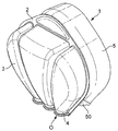
도 la 는 본 발명의 제 1 실시형태에 따른 카드의 상면 사시도를 보여준다.
도 lb 는 도 la 에 따른 카드의 저면 사시도를 보여준다.
도 2a 는 본 발명의 제 2 실시형태에 따른 카드의 저면 사시도를 보여준다.
도 2b 는 도 2a 에 따른 캡슐용 실링 부재의 개략도를 보여준다.
도 2c 는 도 2a 에 나타낸 바와 같은 제 2 실시형태에 따른 관통 수단을 보여준다.
도 3a 는 본 발명의 제 3 실시형태에 따른 카드의 상면 사시도를 보여준다.
도 3b 는 도 3a 에 따른 카드의 저면 사시도를 보여준다.
도 4a 는 본 발명의 제 4 실시형태에 따른 카드의 상면 사시도를 보여준다.
도 4b 는 도 4a 에 따른 카드의 저면 사시도를 보여준다.
도 5a 는 본 발명의 제 5 실시형태에 따른 카드의 저면 사시도를 보여준다.
도 5b 는 도 5a 에 나타낸 바와 같은 제 5 실시형태에 따른 정적 혼합기를 보여준다.
도 6a 는 본 발명의 제 6 실시형태에 따른 카드의 상면도를 보여준다.
도 6b 는 도 6a 에 따른 카드의 사시도를 보여준다.
도 6c 는 도 6a 에 따른 카드의 측면도를 보여준다.
도 7a 는 디스펜싱 부재를 포함하는 도 6a 에 따른 카드의 상면도를 보여준다.
도 7b 는 관통 수단을 또한 보여주는 도 7a 에 따른 카드의 저면 사시도를 보여준다.
도 7c 는 도 7a 에 따른 카드의 디스펜싱 부재의 사시도를 보여준다.
도 7d 는 도 7c 에 따른 디스펜싱 부재의 정면도 및 측면도를 보여준다.
도 7e 는 도 7b 에 따른 카드의 관통 수단의 상면 사시도를 보여준다.
도 7f 는 도 7e 에 따른 관통 수단의 저면 사시도를 보여준다.
도 8a 는 클램핑 수단을 포함한 본 발명의 제 7 실시형태에 따른 카드의 상면 사시도를 보여준다.
도 8b 는 도 8a 에 따른 카드의 기능부의 상면 사시도를 보여준다.
도 8c 는 도 8b 에 도시된 부분의 저면 사시도를 보여준다.
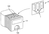
도 9a 는 본 발명의 일 실시형태에 따른 식품 및 음료 제조 기기를 가지는 본 발명에 따른 식품 및 음료 제조 시스템의 사시도를 보여준다.
도 9b 는 본 발명의 다른 실시형태에 따른 식품 및 음료 제조 기기를 가지는 본 발명에 따른 식품 및 음료 제조 시스템의 사시도를 보여준다.
도 10a 는 도 la 에 따른 카드를 가지는 본 발명에 따른 식품 및 음료 제조 시스템의 개략적 측면도를 보여준다.
도 10b 는 도 3a 에 따른 카드를 가지는 본 발명에 따른 식품 및 음료 제조 시스템의 개략적 측면도를 보여준다.
도 11a 는 도 7a 에 따른 카드와 식품 및 음료 제조 기기의 디스펜싱 부재들을 가지는 본 발명에 따른 식품 및 음료 제조 시스템의 저면 사시도를 보여준다.
도 l1b 는 디스펜싱 부재의 개략적 측면도 및 상면도를 보여준다.
도 12 는 공지된 캡슐을 포함하는 공지된 음료 제조 시스템을 보여준다.FIG. 1A is a top perspective view of a card according to a first embodiment of the present invention. FIG.
Figure lb shows a bottom perspective view of the card according to Figure la.
2A shows a bottom perspective view of a card according to a second embodiment of the present invention.
Figure 2b shows a schematic view of the sealing member for a capsule according to Figure 2a.
Fig. 2c shows the penetrating means according to the second embodiment as shown in Fig. 2a.
3A is a top perspective view of a card according to a third embodiment of the present invention.
Figure 3b shows a bottom perspective view of the card according to Figure 3a.
4A is a top perspective view of a card according to a fourth embodiment of the present invention.
Figure 4b shows a bottom perspective view of the card according to Figure 4a.
5A is a bottom perspective view of a card according to a fifth embodiment of the present invention.
FIG. 5B shows a static mixer according to a fifth embodiment as shown in FIG. 5A.
6A shows a top view of a card according to a sixth embodiment of the present invention.
Figure 6b shows a perspective view of the card according to Figure 6a.
Figure 6c shows a side view of the card according to Figure 6a.
Figure 7a shows a top view of the card according to Figure 6a, including the dispensing member;
Figure 7b shows a bottom perspective view of the card according to Figure 7a also showing penetrating means.
Figure 7c shows a perspective view of the dispensing member of the card according to Figure 7a.
Figure 7d shows a front view and a side view of the dispensing member according to Figure 7c.
FIG. 7E shows a top perspective view of the penetrating means of the card according to FIG. 7B. FIG.
Fig. 7f shows a bottom perspective view of the penetrating means according to Fig. 7e.
8A shows a top perspective view of a card according to a seventh embodiment of the present invention including a clamping means.
Figure 8b shows a top perspective view of the functioning portion of the card according to Figure 8a.
FIG. 8C shows a bottom perspective view of the portion shown in FIG. 8B.
9A shows a perspective view of a food and beverage manufacturing system according to the present invention having a food and beverage manufacturing apparatus according to an embodiment of the present invention.
Figure 9b shows a perspective view of a food and beverage manufacturing system according to the present invention having a food and beverage manufacturing device according to another embodiment of the present invention.
Figure 10a shows a schematic side view of a food and beverage production system according to the present invention with a card according to figure la.
Fig. 10b shows a schematic side view of a food and beverage production system according to the invention with a card according to Fig. 3a.
Fig. 11A shows a bottom perspective view of a food and beverage manufacturing system according to the present invention having a card according to Fig. 7A and dispensing members of a food and beverage manufacturing machine.
FIG. 11B shows a schematic side view and a top view of the dispensing member.
Figure 12 shows a known beverage manufacturing system comprising known capsules.
도 1 내지 도 11 은 모두 본 발명에 따른 식품 또는 음료 성분들 (하기에서 또한 "성분들" 로서 지칭됨) 을 담기 위한 카드 (1) 를 보여준다. 상기 성분들은 다층 음료 (예컨대 커피뿐만 아니라 크리머, 우유 또는 우유 거품, 다층의 고온 또는 저온 유제품 음료들) 또는 수프 또는 다른 식품 제품과 같은 복잡한 음료 또는 액체/점성이 있는 식품을 제조하기에 임의의 적합한 성분들일 수 있다. 성분들은 예를 들어 가용성 커피 또는 차, 코코아, 우유 또는 우유 분말, 수프 분말, 영아용 조제식, 특정 요구에 맞춘 영양 제품들, 및 그것의 조합물들일 수 있다. 분말 성분들에 부가적으로 또는 대신하여, 액체 또는 겔화 농축물들이 또한 사용될 수 있다. 특히 수프와 같은 식사, 유아용 식사, 특정 식이요법을 필요로 하는 사람들을 위한 식사를 제조하기 위해, 성분들은 가용성인 분말화, 액체 또는 겔화 성분들, 및 허브, 동결 건조 야채 등과 같은 비가용성 피스들 (pieces) 을 포함할 수 있다.1 to 11 show a
카드 (1) 는 강성 재료로 만들어진 실질적으로 평면의 베이스부 (2) 를 포함한다. "강성" 은, 베이스부 (2) 가 (특히 제품 제조 중) 그것의 평평하거나 평면인 레이아웃을 유지하고 최대 탄성적으로 변형가능한 것을 의미한다. 베이스부 (2) 는 바람직하게 플라스틱 또는 다른 강성 재료, 예컨대 알루미늄 등으로 만들어진다. 카드 (1) 또는 더 양호하게는 베이스부 (2) 가 정사각형 또는 직사각형 기본 형태를 가질 수 있어서 도 12 에 나타낸 것과 같은 원형 캡슐의 제조와 비교해 카드 (1) 의 제조 중 훨씬 더 적은 폐기물을 발생한다. 하지만, 베이스부 (2) 는 임의의 원하는 형상을 가질 수 있고, 상기 형상에 대한 원하는 패키징 설계 및/또는 기술적 제약에 의존할 수 있다.The
카드 (1) 는 성분들을 저장하기 위한 적어도 2 개의 격실들 (3) 을 추가로 포함한다. 실시형태들에서는, 3 개의 격실들 (3) 을 가지는 카드들 (1) 이 나타나 있지만, 본 발명은 이에 제한되지 않는다. 격실들 (3) 은 베이스부 (2) 의 평면으로부터 동일한 방향으로 모두 돌출한 리세스들에 의해 형성된다. 격실들 (3) 은 베이스부 (2) 와 일체로 형성될 수 있다. 대안적으로, 격실들 (3) 중 적어도 하나는 가요성 (포일) 부재, 예컨대 알루미늄 포일로 만들어질 수 있다. 상기 포일 부재는 그 후 베이스부 (2) 에서 개구 (30) 둘레에 제공되고, 바람직하게 실링된다. 베이스부 (2) 에서 개구 (30) 는 리세스, 즉 격실 (3) 을 형성하기 위해서 포일 부재 (또는 격실 벽 (31)) 에 의해 경계가 정해진 공간으로 통과한다.The card (1) further comprises at least two compartments (3) for storing the components. In embodiments,
각각의 격실 (3) 로부터, 베이스부 (2) 의 평면을 따라 배출부 (4) 가 연장된다. 배출부들 (4) 은 그것의 상류 단부에서 격실 (3) 과, 그것의 하류 단부에서 카드 (1) 의 출구 (0) 와 유동적으로 연결된다. 격실들 (3) 처럼, 또한 배출부들 (4) 은 리세스들에 의해 형성되고 리세스들은 베이스부 (2) 의 평면으로부터 동일한 방향으로, 즉 격실들 (3) 과 같이 돌출해 있다. 카드 (1) 의 배출부들 (4) 은 바람직하게 베이스부 (2) 와 일체로 형성된다. 배출부들 (4) 중 적어도 하나는 채널로서 형성될 수 있다.From each
카드 (1) 는 적어도 하나의 실링 부재 (5) 를 추가로 포함하고, 이 실링 부재는 베이스부 (2) 에 제공 (예컨대 실링) 되어 모든 격실들 (3) 또는 개구들 (30) 및 배출부들 (예컨대 채널들) (4) 을 덮어서 카드 (1) 의 베이스부 측에서 격실들 (3) 및 배출부들 (4) 의 개구들 (30, 40) 을 완전히 한정한다. 실링 부재 (5) 는 바람직하게 알루미늄 또는 PET 막으로 만들어지지만, 본 발명은 이에 제한되지 않는다. 하나의 실링 부재 (5) 가 카드의 베이스부 측을 완전히 덮는 실시형태가 여기에 나타나 있지만, 각각의 격실이 생산 라인에서 개별적으로 실링될 수 있음을 주목해야 한다. 이것은, 격실들이 다른 유형의 성분들 (예컨대 분말, 농축물 또는 젤리) 로 충전될 때 특히 유리할 수도 있다.The
도 la 및 도 lb 에 도시된 바와 같은 일 실시형태에 따르면, 카드 (1) 의 배출부들 또는 채널들 (4) 은 각각의 격실 (3) 로부터 베이스부 (2) 의 측방향 단부 구역 (R) 을 향해 연장되어서 제품 또는 적어도 그것의 일부를 디스펜싱하기 위한 카드 (1) 의 출구 (0) 를 형성한다.The outlets or
도 3a 및 도 3b 에 도시된 바와 같은 다른 실시형태에 따르면, 카드 (1) 의 배출부들 (4) 은 각각의 격실 (3) 로부터 공통 혼합 챔버 (6) 를 향해 그 챔버까지 연장된다. 따라서, 배출부들 (4) 은 각각의 격실 (3) 과 공통 혼합 챔버 (6) 를 유동적으로 연결한다. 카드 (1) 의 배출부들 (4) 과 같이, 추가 배출부 (7; 예컨대 혼합 채널) 는 혼합 챔버 (6) 로부터 베이스부 (2) 의 평면을 따라, 바람직하게 베이스부 (2) 의 측방향 단부 구역 (R) 을 향해 그 단부 구역까지 연장되어서 카드 (1) 의 출구 (0) 를 형성한다. 카드 (1) 의 격실 (3) 및 배출부들 (4) 과 비슷하게, 또한 혼합 챔버 (6) 및 추가 배출부 또는 혼합 채널 (7) 양자는 베이스부 (2) 의 평면으로부터 동일한 방향으로 돌출한 리세스들에 의해 형성된다. 단지 실링 부재 (5) 만 또한 혼합 챔버 (6) 및 추가 배출부 (7) 를 덮어서 카드 (1) 의 베이스부 측에서 각각의 개구들 (60, 70) 을 완전히 한정한다.According to another embodiment as shown in FIGS. 3A and 3B, the
프로세싱 부재는 실링 부재 (5) 에 의해 덮여있는 배출부들 (4, 7) 중 적어도 하나에 제공될 수 있다. 다시 말해서, 프로세싱 부재는 각각의 배출부 (4, 7) 내에 배치되고 또한 실링 부재 (5) 에 의해 덮여있어서 배출부 (4, 7) 와 실링 부재 (5) 사이에 끼여있다. 대안적으로, 프로세싱 부재는, 또한, 예컨대 본원에서 후술되는 식품 및 음료 제조 기기 (D) 의 일부로서 실링 부재 (5) 에 의해 덮여있는 배출부들 (4, 7) 중 적어도 하나와 상호작용하도록 제공될 수 있다.The processing member may be provided in at least one of the outlets (4, 7) covered by the sealing member (5). In other words, the processing member is disposed in each of the
예를 들어, 프로세싱 부재는 도 5a 의 실시형태에서 도시된 바와 같은 정적 혼합기 (8) 일 수 있다. 이러한 정적 혼합기 (8) 를 위해 가능한 레이아웃은 또한 도 5b 에 나타나 있다. 정적 혼합기 (8) 에 의해 각각의 배출부 (4, 7) 를 통과한 성분들을 충분히 혼합할 수 있다. 또한, (가압된) 공기는, 바람직하게 채널형 배출부 (4, 7) 를 통과하는 바람직하게 액체 성분들 또는 (중간) 제품으로 주입된 공기로 인해 발포성 제품을 형성하도록, 바람직하게 정적 혼합기 (8) 의 상류 단부에서, 정적 혼합기 (8) 를 포함하는 배출부 (4, 7) 로 실링 부재 (5) 를 통하여 진입 또는 주입될 수 있다. 정적 혼합기 (8) 는 카드 (1) 의 적어도 하나 이상 또는 바람직하게 모든 배출부들 (4) 에 배치될 수 있다. 부가적으로 또는 대안적으로, 정적 혼합기 (8) 는 또한 추가 배출부 (7; 즉 혼합 채널) 내에 제공될 수 있다.For example, the processing member may be a
도 2a 에 도시된 바와 같은 다른 실시형태에 따르면, 프로세싱 부재는 또한 유동 제어 요소 (9) 일 수 있다. 도 2a 에서 볼 수 있듯이, 유동 제어 요소 (9) 는 카드 (1) 의 각각의 배출부 또는 채널 (4) 을 따라 연장되고 또한 상기 배출부 (4) 를 따라, 즉 그것의 종방향으로 이동가능하다. 유동 제어 요소 (9) 는 바람직하게 채널 또는 배출부 벽들 (41) 및 실링 부재 (5) 에 의해 한정되는 카드 (1) 의 배출부 또는 채널 (4) 을 (플러그와 같은 방식으로) 충전하도록 단면을 포함한다. 도 2a 및 도 2c 에서 볼 수 있듯이, 유동 제어 요소 (9) 는 따라서 배출부들 (4, 7) 과 연관되도록 반원형 보디 (94) 를 포함하고, 보디 (94) 는 실링 부재 (5) 와 접촉하도록 평평한 상단부 (95) 를 가지고 있다.According to another embodiment as shown in Fig. 2A, the processing member may also be a
바람직한 실시형태에 따르면, 제 2 채널들 (90) 은 관통 수단 (9) 상에 또는 내부에 형성된다. 도 2c 에서 볼 수 있듯이, 제 2 채널들 (90) 은 실제로 전체 유동 제어 요소 (9) 를 따라 (그것의 종방향 축선 (L) 을 따라) 연장되어서 격실들 (3) 에 저장된 성분들이 상기 제 2 채널들 (90) 을 통하여 카드 (1) 의 배출부들 (4) 로 통과할 수 있도록 허용한다. 하지만, 이것은 또한 각각의 배출부 (4, 7) 보다 작은 직경을 가지는 유동 제어 요소 (9) 에 의해 획득될 수 있다. 유동 제어 요소 (9) 에서 채널의 직경은, 통과해야 하는 입자들의 크기 및 요구되는 전단 응력에 의존한다. 채널(들)의 단면이 더 작을수록, 유체의 속도와 음료 제품에 유도된 전단 응력은 더 높을 것이다. 전단 응력은 제품의 최종 텍스처에 중요한 영향을 미친다.According to a preferred embodiment, the
유동 제어 요소 (9) 의 단부 - 바람직하게 격실 (3) 에 대향한 단부 또는 더 양호하게는 유동 제어 요소 (9) 의 하류 단부 - 는 (카드 (1) 의 개구 (0) 와 동일할 수 있는) 카드 (1) 의 배출부들 (4) 의 개구 (0) - 바람직하게 각각의 격실 (3) 에 대향한 개구 (0) 또는 양호하게는 배출부 (4) 의 하류 단부 - 를 폐쇄하는 폐쇄 수단 (50) 을 침투하기 위한 관통 부재 (91) 를 포함한다. 배출부들 (4) 이 격실 (3) 로부터 베이스부 (2) 의 측방향 단부 구역 (R) 까지 연장하여 카드 (1) 의 출구 (0) 를 형성하는 경우에, 폐쇄 수단 (50) 은 실링 부재 (5) 의 일체부로서 형성될 수 있다. 도 2b 를 참조하면, 따라서 실링 부재 (5) 는 측방향 단부 구역 (R) 과 따라서 또한 카드 (1) 의 출구(들) (0) 를 덮도록 (예컨대 90°의 각도만큼) 베이스부 (2) 의 가장자리 (E) 에서 구부러지는 연장부 (50) 를 포함할 수 있다. 대안적으로, 유체가 주입되는 격실들 및 출구를 각각 실링하기 위해 2 개의 다른 실링 막들이 사용될 수 있다. 이 2 개의 막들은 다른 기계적 특성들을 가질 수 있다. The end of the flow control element 9-preferably the end opposite to the
도 3a 에 따른 실시형태의 경우에, 각각의 배출부들 또는 채널들 (4) 은 또한 바람직하게 혼합 챔버 (6) 에 가까운 단부에서 실링부에 의해 폐쇄될 수 있고, 이 실링부는 그 후 각각의 격실 (3) 을 개방하기 위해서 각각의 배출부들 (4) 에 배치된 유동 제어 요소 (9) 에 의해 관통될 수 있다. 더욱이, 유동 제어 요소 (9) 는 또한 카드 (1) 를 개방하기 위해서 카드 (1) 의 출구 (0) 에 가까운 단부에 바람직하게 제공된 실링부를 관통하도록 된 혼합 채널 (7) 내에 배치될 수 있다.In the case of the embodiment according to Fig. 3a, each discharge or
바람직한 실시형태에 따르면, 유동 제어 요소 (9) 는 각각의 배출부 (4, 7) 를 따라 유동 제어 요소 (9) 를 이동시키도록 실링 부재 (5) 를 통하여 반경방향으로 돌출하는 작동 부재 (92) 를 포함한다. 다시 말해서, 작동 부재 (92) 는 관통 수단 (9) 의 이동가능한 방향 또는 종방향 축선 (L) 에 대해 실질적으로 직교하는 방향으로 유동 제어 요소 (9) 로부터 연장되고; 그 후, 작동 부재 (92) 가 개구 (40, 70) 및 상기 개구 (40, 70) 를 덮는 실링 부재 (5) 를 통하여 카드 (1) 로부터 튀어나오도록 유동 제어 요소 (9) 는 각각의 배출부 (4, 7) 에 배치된다. 따라서, 카드 (1) 가 상기 기기 (D) 에 삽입될 때, 예컨대 식품 및 음료 제조 기기 D (하기에서 또한 "제조 기기" 또는 "기기" 로도 지칭됨) 의 액추에이터 수단에 의해, 외부로부터 유동 제어 요소 (9) 를 이동시킬 수 있다 (도 9a 및 도 9b 참조). 따라서, 도 2a 에 나타낸 것처럼 배출부 (4) 에서 유동 제어 요소 (9) 의 위치는 폐쇄 수단 (50) 또는 실링부를 관통 또는 침투하기 전 초기 위치를 나타낸다. 작동 부재 (92) 를 통하여 폐쇄 수단 (50) 을 향해 유동 제어 요소 (9) 를 이동시킬 때, 상기 폐쇄 수단 (50) 은 관통 수단 (9) 의 관통 부재 (91) 에 의해 침투될 것이다. 각각의 배출부들 또는 채널들 (4, 7) 을 통하여 격실 (3) 또는 혼합 챔버 (6) 로부터 성분들 또는 (중간) 제품들의 이송은, 각각의 배출부 (4, 7) 의 상류 단부와 하류 단부 사이에 유체 연결부를 형성하는 관통 부재 (9) 에 제공된 제 2 채널들 (90) 을 통하여 획득된다.According to a preferred embodiment the
바람직한 실시형태에 따르면, 유동 제어 요소 (9) 는 관통 수단 (9) 의 초기 위치에서 배출부 (4, 7) 로 통과하는 격실 (3)/혼합 챔버 (6) 의 출구 (32, 61) 에서 떨어져 격실 (3)/혼합 챔버 (6) 내에 위치결정된 반경방향으로 연장되는 헤드부 (93) 를 포함한다. 확장 헤드부 (93) 는 배출부 (4, 7) 보다 더 큰 직경을 가져서 유동 제어 요소 (9) 가 카드 (1) 밖으로 슬라이딩하여 떨어지는 것을 막도록 스토퍼로서 사용된다. 관통 부재 (9) 가 폐쇄 수단 (50) 을 침투하거나 실링부 및 헤드부 (93) 가 격실 (3)/혼합 챔버 (6) 의 출구 (32, 61) 에 놓여질 때 여전히 성분들이 제 2 채널들 (90) 을 따라 통과할 수 있도록 허용하기 위해서, 제 2 채널들 (90) 은 관통 수단 (9) 의 헤드부 (93) 를 통하여 연장된다.According to a preferred embodiment, the
하지만, 도면들에 도시되지 않은 다른 특정한 실시형태에 따르면, 제 2 채널들 (90) 은 관통 수단 (9) 의 헤드부 (93) 를 통과하지 않는다. 상기 실시형태에 따르면, 헤드부 (93) 가 격실 (3)/혼합 챔버 (6) 의 내부면 또는 출구 (32, 61) 에 놓여있지 않는 동안, 유동 제어 요소 (9) 는 도 2a 에 나타낸 것과 같은 초기 위치로부터 관통 부재 (9) 가 폐쇄 수단 (50) 또는 실링부를 침투하는 중간 위치까지 이동될 수 있다. 이 중간 위치에서, 성분들 또는 (중간) 제품들은 제 2 채널들 (90) 을 통하여 배출부들 (4, 7) 을 통과할 수 있다. 차단 위치에서, 헤드부 (93) 가 격실 (3)/혼합 챔버 (6) 의 내부면 또는 출구 (32, 61) 에 놓여서 배출부들 (4, 7) 및 제 2 채널들 (90) 로부터 격실 (3)/혼합 챔버 (6) 를 폐쇄할 때까지 유동 제어 요소 (9) 는 추가로 이동한다. 그러므로, 각각의 격실 (3) 또는 혼합 챔버 (6) 로부터 성분들의 처리가 억제된다. 다시 유동 제어 요소 (9) 를 그것의 중간 위치로 이동시킬 때, 각각의 격실 (3) 또는 혼합 챔버 (6) 로부터 채널들 (4, 7) 을 통하여 성분들의 유동이 다시 가능하게 된다.However, according to another specific embodiment not shown in the drawings, the
도 4a 및 도 4b 에 도시된 바와 같은 또다른 실시형태에 따르면, 프로세싱 부재는 혼합 챔버 (6) 에 제공된 유동 제어 요소 (10) 일 수 있다. 상기 유동 제어 요소 (10) 는 바람직하게 카드 (1) 의 각각의 배출부들 (4) 로 연장되는 제 1 관통 부재들 (11) 을 갖는다. 유동 제어 요소 (10) 는 추가 배출부 또는 혼합 채널 (7) 로 연장되는 제 2 관통 부재 (12) 를 추가로 포함할 수 있다. 이 실시형태에서, 격실들 (3) 은 실링부에 의해 카드 (1) 또는 혼합 챔버 (6) 의 배출부들 (4) 로부터 실링된다. 혼합 채널 (7) 의 출구 (0) 는 또한 대응하는 실링부 또는 실링 부재 (5) 의 폐쇄 수단 (50) 에 의해 실링된다.According to another embodiment, as shown in Figs. 4A and 4B, the processing member may be a
카드 (1) 의 각각의 배출부들 (4) 로부터 격실들 (3) 을 실링하는 적어도 하나, 바람직하게 모든 실링부들이, 베이스부 (2) 의 평면을 따라 적어도 제 1 방향으로 유동 제어 요소 (10) 를 이동시킴으로써, 제 1 관통 부재들 (11) 에 의해 관통될 수 있도록 유동 제어 요소 (10) 는 실링 부재 (5) 를 통하여 반경방향으로 돌출한 작동 부재 (13) 를 포함할 수도 있다. 하지만, 또한, 각각의 실링부들의 선택적 (예컨대, 그룹화 또는 후속) 개방을 허용하도록 유동 제어 요소 (10) 가 베이스부 (2) 의 평면을 따라 상기 하나의 제 1 방향보다 많은 방향으로 이동될 수 있는 가능성이 있다.At least one and preferably all of the sealing parts for sealing the
베이스부 (2) 의 평면을 따라 제 2 방향으로 유동 제어 요소 (10) 를 이동시킬 때, 추가 배출부 또는 혼합 채널 (7) 의 출구 (0) 를 실링하는 실링부가 관통될 수 있다. 따라서, 혼합 챔버 (6) 로부터 혼합 성분들 또는 중간 제품을 방출시킬 수 있다. 예컨대 도 2c 에 도시된 대로 유동 제어 요소 (9) 에 대해 또한 보여주는 것처럼 관통 요소 (10) 내에 채널들을 제공함으로써, 관통 요소 (10) 의 특정한 다른 위치에서 각각의 배출부들 (4, 7) 을 유체 등이 통과할 수 있도록 허용하면서 제 1 및 제 2 관통 부재가 특정 위치에서 각각의 배출부들 또는 채널들 (4, 7) 을 폐쇄하도록 제 1 및 제 2 관통 부재 (11, 12) 가 설계될 수 있다.When moving the
바람직한 실시형태에 따르면, 제 1 방향 및 제 2 방향은 바람직하게 서로 반대이어서 (도 4b 의 화살표 14 참조) 관통 요소 (10) 및 따라서 제조 기기 (D) 의 대응하는 액추에이터 수단의 운동을 용이하게 한다. 또한, 관통 부재들 (11, 12) 의 종방향 연장선 이외의 방향으로 관통 부재 (10) 를 이동시킬 때 각각의 관통 부재 (11, 12) 의 탄성 편향을 허용하도록 관통 요소 (10) 는 바람직하게 플라스틱 재료로 만들어진다. 그러므로, 상기 실시형태에 의하여, 단순히 반대 (제 2) 방향으로 관통 요소 (10) 를 변위시킴으로써 혼합 챔버 (6) 내에서 혼합된 제품이 후에 카드 (1) 로부터 디스펜싱될 수 있고 하나의 단일 (제 1) 방향으로 관통 요소 (10) 를 변위시킴으로써 각각의 격실들 (3) 이 개방될 수 있다.According to a preferred embodiment, the first direction and the second direction are preferably opposite to each other (see
격실들 (3) 에 저장된 각각의 성분들의 유동성에 따라, 실링부가 이미 침투된 경우에, 각각의 실링부의 선택적 또는 순차적 침투에 의해서 또는 각각의 격실들 (3) 에서 유체 (예컨대 공기 또는 물) 의 (후속) 선택적 주입에 의해서 상기 성분들은 혼합 챔버 (6) 로 진입하도록 제어될 수 있다.Depending on the fluidity of the respective components stored in the
도 6a 내지 도 6c 에 도시된 바에 따른 또다른 실시형태에 따르면, 본 발명에 따른 카드 (1) 가 제공된다. 도시된 카드 (1) 는 3 개의 격실들 (3) 을 포함하지만, 본 발명은 상기 개수의 격실들 (3) 에 제한되지 않는다. 배출부들 (4) 은 모두 각각의 격실 (3) 로부터 베이스부 (2) 의 측방향 단부 구역 (R) 을 향해 그리고 상기 단부 구역까지 연장되어서 출구 (0) 를 형성한다. 카드 (1) 는또한 혼합 챔버 (6) 를 포함할 수도 있고 배출부 (7) 는 카드 (1) 의 출구 (0) 를 형성하도록 베이스부 (2) 의 측방향 단부 구역 (R) 을 향해 그리고 상기 단부 구역까지 또한 연장될 수 있다. 격실들 (3) 뿐만 아니라 대응하는 배출부들 (4) 은 모두 실링 부재 (5) 에 의해 덮여있다. 바람직하게, 또한 출구 (0) 는 도 6b 및 도 6c 에서 분명히 볼 수 있는 것처럼 실링 부재 (5) 의 연장부 (50) 에 의해 덮여있다. 하지만, 출구 (0) 는 또한 별도의 폐쇄 수단에 의해 덮여있을 수 있다.According to another embodiment as shown in Figs. 6A to 6C, a
도 6 에 나타난 것처럼 카드 (1) 는 채널들 (21) 을 가지는 디스펜싱 부재 (20) 를 추가로 포함할 수 있고, 바람직하게 가요성 채널들 또는 채널들 (21) 은 적어도 가요적 변형부 (22) 를 가지고; 이것은 도 7 및 도 8 에 나타나 있다. 카드 (1) 의 배출부들 (4) 또는 추가 배출부 (7) 가 상기 디스펜싱 부재 (20) 의 채널들 (21) 로 통과하도록 디스펜싱 부재 (20) 는 베이스부 (2) 에 배열되거나 부착된다. 바람직하게, 채널들 (21) 은 따라서 베이스부 (2) 의 측방향 단부 구역 (R) 으로부터 연장된다. 바람직하게 디스펜싱 부재 (20) 는 베이스부 (2) 의 측방향 단부 구역 (R) 에 연결되고, 바람직하게 실링되는 연결부 (25) 를 갖는다. 디스펜싱 부재 (20) 를 측방향 단부 구역 (R) 에 연결하기 위해, 열적 또는 초음파 납땜 수단이 사용될 수 있다.6, the
채널들 (21) 은 각각 (가요성) 튜브들 (미도시) 에 의해 형성될 수 있고, 각각은 베이스부 (2) 로부터, 특히 베이스부 (2) 의 측방향 단부 구역 (R) 에서 카드 (1) 의 출구(들) (0) 로부터 연장된다. 튜브들은, 각각, 특히 카드 (1) 의 출구 (0) 를 형성하는 단부에서 각각의 배출부 (4, 7) 에 단순히 삽입되거나 끼워맞추어질 수 있다.
대안적으로, 채널들 (21) 은 디스펜싱 부재 (20) 의 베이스부 (23) 의 평면으로부터 동일한 방향으로 돌출하는 리세스들에 의해 형성될 수 있다. 디스펜싱 부재 (20) 의 베이스부 (23) 는 바람직하게 카드 (1) 의 베이스부 (2) 와 동일한 재료로 만들어지고 이 2 개의 베이스부들은 바람직하게 동일한 평면에서 연장된다. 채널들 (21) 은 또한 바람직하게 카드 (1) 의 베이스부 (2) 의 리세스들과 (각각의 베이스부들 (2, 23) 의 상기 공통 평면에 대해) 동일한 방향으로 연장된다.Alternatively, the
디스펜싱 부재 (20) 의 리세스들은 또한 바람직하게 베이스부 (23) 에 제공된 실링 부재 (24) 에 의해 덮여있어서 디스펜싱 부재 (20) 의 베이스부 측에서 채널들 (21) 을 완전히 한정한다. 특정 실시형태에서, 실링 부재 (24) 는 카드 (1) 의 실링 부재 (5) 의 돌기부 (50) 에 의해 형성될 수 있다. 실링 부재 (24) 는 바람직하게 실링 부재 (5) 와 동일한 재료로 만들어진다.The recesses of the dispensing
폐쇄 수단 (50) (바람직하게 실링 부재 (5) 의 연장부 (50)) 이 전술한 대로 배출부들 (4, 7) 과 디스펜싱 부재 (20) 사이에 제공될 때, 격실들 (3) 및/또는 혼합 챔버 (6) 는 채널들 (21) 로부터 밀봉 분리된다. 그 후, 유동 제어 요소는 디스펜싱 부재 (20) 의 각각의 채널들 (21) 을 따라 연장되는 관통 수단 (26) 일 수 있다. 그 후, 상기 관통 수단 (26) 은 바람직하게 그것의 벽들 (27) 및 디스펜싱 부재 (20) 의 실링 부재 (24) 에 의해 한정되는 채널들 (21) 을 충전하도록 단면을 갖는다. 바람직하게, 채널들 (260) 은 관통 수단 (26) 상에 또는 안에 형성되고 이 채널들 (260) 은, 성분들이 디스펜싱 부재 (20) 를 통과할 수 있도록 허용하기 위해서 전체 관통 수단 (26) 을 따라 축선방향으로 연장된다. 상류 단부에서 관통 수단 (26) 의 단부는 바람직하게 폐쇄 수단 (도 7b 및 도 8c 에서 도면부호 50) 을 침투하기 위한 관통 부재 (261) 를 포함한다. 관통 수단 (26) 은 바람직하게 채널 (21) 내에서 고정된 위치에 홀딩된다. (물 또는 공기와 같은) 유체들의 주입으로 인해 격실 (3) 및/또는 혼합 챔버 (6) 내부의 압력이 증가함에 따라, 폐쇄 수단 (50) 은 관통 수단을 향해, 특히 그것의 관통 부재 (261) 를 향해 변형된다 (즉, 불룩해진다). 폐쇄 수단 (50) 의 대응하는 변형을 유발하는 카드 (1) 또는 각각의 격실 (3) 또는 혼합 챔버 (6) 내부의 원하는 미리 규정된 압력에서, 폐쇄 수단 (50) 은 관통 부재 (261) 에 도달하고 관통 부재는 따라서 폐쇄 수단 (50) 을 관통 및 개방시켜서 카드 (1) 로부터 채널들 (21) 을 통하여 채널들 (21) 의 하류 단부에서 카드 (1) 의 출구 (0) 까지 성분들 또는 (중간) 제품들이 디스펜싱될 수 있도록 허용한다. 디스펜싱 부재 (20) 의 채널들 (21) 뿐만 아니라 격실들 (3)/혼합 챔버 (6) 내부 압력은 배출된 성분들 또는 제품들의 가속을 유발한다. 그에 맞춰 관통 수단 (26) 또는 그것의 채널들 (260) 을 설계할 때, 전단 응력이 추가로 증가될 수 있어서 디스펜싱된 제품의 텍스처의 변화, 예컨대 발포성 또는 증가한 점도를 가능하게 한다. 관통 수단 (26) 은 전술한 유동 제어 요소 (9) 와 유사하거나 동일한 방식으로 설계될 수 있음에 주목한다.When the closing means 50 (preferably the
바람직한 실시형태에서, 관통 수단 (26) 은 또한 디스펜싱 부재 (20) 의 각각의 채널 (21) 을 따라 이동가능하다. 이 경우에, 관통 수단 (26) 은 바람직하게 상기 디스펜싱 부재 (20) 의 각각의 채널 (21) 을 따라 관통 수단 (26) 을 이동시키도록 디스펜싱 부재 (20) 의 실링 부재 (24) 를 통하여 반경방향으로 돌출하는 작동 부재 (262) 를 포함한다. 그러므로, 이미 전술한 바와 같이, 카드 (1) 를 개방하기 위해 도달될 타이밍과 압력은 관통 수단 (26) 을 활성 변위시킴으로써 보다 정확하게 영향을 받을 수 있다.In a preferred embodiment, the penetrating
전술한 바와 같은 정적 혼합기 (8) 는 또한 채널들 (21) 중 적어도 하나 내부에 배치될 수 있음에 주목한다. 또한, 채널들 (260) 을 가지는 관통 수단 (26) 이 정적 혼합기로서 형성되는 것이 또한 가능하다. 유동 제어 요소 (9) 또는 관통 요소 (10) 의 경우에도 또한 같다.It should be noted that the
또다른 실시형태에 따르면, 디스펜싱 부재 (20) 의 채널들 (21) 은, 채널 (21) 의 단면을 변경함으로써 각각의 채널 (21) 을 통한 (성분들의) 유체 유동을 조정 또는 제어 또는 중단하도록 기기 (D) 의 클램핑 수단 (140) 에 의해 클램핑될 가요적 변형부 (22) 인 클램핑부를 포함한다. 도 8b 및 도 8c 에서 볼 수 있듯이, 제조될 제품 및 상기 제품의 원하는 레이어링 효과에 따라 개별적으로 또는 일괄적으로 활성화될 수 있는 디스펜싱 부재 (20) 의 각각의 채널 (21) 에 하나의 클램핑 수단 (140) 이 제공될 수 있다. 하지만, 하나 이상의 채널들 (21) 이 또한 클램핑 수단 (140) 을 공유할 수 있다. 디스펜싱 수단 (20) 또는 제조 기기 (D) 는 클램핑 수단 (140) 을 가이드하기 위한 가이드 수단 (28) 을 추가로 포함할 수 있다. 따라서, 가이드 수단 (140) 은, 바람직하게, 각각의 채널 (21) 의 종방향 축선에 실질적으로 수직인 방향으로 가이드 수단 (140) 을 변위시킬 수 있도록 가이드 그루브들 (280) 을 포함한다. 가이드 그루브들 (280) 은 바람직하게 변형부 (22) 위에 또는 전방에 위치결정된다.According to yet another embodiment, the
바람직하게 제조 기기 (D) 내에 제공된 상기 클램핑 수단 (140) 을 사용함으로써, 각각의 (가요성) 채널들 또는 튜브들은 선택적으로 클램핑될 수 있어서 디스펜싱될 성분들 또는 제품들의 유동을 개별적으로 연속적으로 제어한다. By using the clamping means 140, which is preferably provided in the manufacturing equipment D, each (flexible) channel or tubes can be selectively clamped so that the flow of components or products to be dispensed can be individually and continuously .
도 8c 에 대해, 클램핑 수단 (140) 은 정적 또는 바람직하게 가동성 관통 수단 (26) 과 조합하여 또한 사용될 수 있다. 변형부 (22) 로 클램핑 수단 (140) 을 프레스할 때, 가동성 관통 수단 (26) 은 채널 (21) 의 변형으로 인해 폐쇄 수단 (50) 을 향해 동시에 이동될 수 있어서 각각의 배출부 (4, 7) 를 개방하고 동시에 채널 (21) 을 폐쇄하고 이 채널은 그 후 제품을 선택적으로 디스펜싱할 준비가 된 상태로 된다.8c, the clamping means 140 may also be used in combination with the static or preferably movable penetrating
또한, 도 6a, 도 7a 및 도 8a 에 나타낸 카드 (1) 에 대해, 카드 (1) 는 또한 브랜딩 또는 카드 (1) 의 성분들 또는 제품에 대한 정보 또는 카드 (1) 등을 사용하기 위한 지시사항을 제공하기 위한 영역 (29) 을 포함할 수 있다. 상기 영역 (29) 은 바람직하게 베이스부 (2) 의 일부, 특히 그것의 측방향 연장부이다. 정보는 예컨대 바코드로, RFID 태그 등으로 기계에 의해 판독가능한 포맷으로 제공될 수 있어서, 그것은 특정 프로토콜에 따라 제품을 자동으로 제조한다.6A, 7A and 8A, the
격실들 (3), 혼합 챔버들 (6), 배출부들 (4, 7) 및 채널들 (21) 의 개수뿐만 아니라 각각의 베이스부 (2, 23) 에서 서로에 대한 그것의 배열은 본 발명에 의해 제한되지 않음을 이해해야 한다. 또한, 모든 프로세싱 부재들이 임의의 원하는 방식으로 조합될 수 있다. 또한, 배출부들 (4) 중 일부는 각각의 격실 (3) 로부터 카드 (1) 의 출구 (0) 를 향해 이 출구까지 연장되고 카드 (1) 의 다른 채널들 (4) 은 하나 또는 복수의 혼합 챔버들 (6) 로 연장되고 이 챔버들로부터 적어도 하나의 혼합 채널 (7) 이 다른 혼합 챔버 (6) 또는 카드 (1) 의 출구 (0) 로 연장되는 것이 가능하다. 모든 실시형태들의 카드들 (1) 은 도 6 내지 도 8 에 대해 설명한 바와 같이 디스펜싱 부재 (20) 를 구비할 수 있다.The arrangement of the
제조 기기 (D) 의 디스펜싱 수단은 리세스들로 진입하도록 선택적으로 이동가능한 유체 주입 수단 (100) 일 수 있다 (도 10a 및 도 10b 참조). 이 점에서, 유체 주입 수단 (100) 은 성분들을 용해시키고 후에 디스펜싱하기 위해 가스 또는 액체 (예컨대 물) 를 주입하기 위해 격실들 (3) 및/또는 혼합 챔버 (6) 로 진입하도록 설계될 수 있다. 유체 주입 수단 (100) 은, 또한, 정적 혼합기 (8) 가 바람직하게 제공되는 각각의 채널들 (4, 7) 을 통과하는 성분들 또는 (중간) 제품들을 발포시키도록 가스 (예컨대 공기) 를 주입하기 위해 채널들 (4, 7) 로 진입하도록 설계될 수 있다.The dispensing means of the manufacturing machine (D) can be a fluid injection means (100) which is selectively movable to enter the recesses (see Figs. 10A and 10B). In this regard, the fluid injection means 100 can be designed to enter the
도 11a 에 대해, 카드 (1) 뿐만 아니라 유체 주입 수단 (100) 을 가지는 시스템 (S) 이 (개략적으로) 나타나 있다. 분명히 볼 수 있듯이, 유체 주입 수단 (100) 은 격실들 (3) 에, 그것의 출구 가까이에, 즉 배출부들 (4) 가까이에 제공 (삽입) 된다. 또한, 유체 주입 수단 (100) 은 측면도에서 각각의 배출부 (4) 의 종방향 축선에 대해 오프셋되어있다. 그러므로, 충분한 제품 혼합 및 용해를 수행하도록 격실 (3) 내부에 최대 난류가 획득될 수 있다. 도 l1b 는 주입 니들로서 형성되는 유체 주입 수단 (100) 의 특징을 보여준다. 분명히 볼 수 있듯이, 유체 채널 (101) 은 유체 주입 수단 (100) 의 종방향 축선 (102) 과 평행하지만 오프셋되어있다. 그러므로, 유체 채널 (101) 의 주입 개구 (103) 는 대개 유체 주입 수단 (100) 의 테이퍼 단부 (104) 의 일측으로 개방되어서 주입된 유체가 배출부들 (4) 을 통하여 직접 빠져나가는 것을 막지만 격실 (3) 내에 최대 난류를 획득한다. 상기 유체 주입 수단 (100) 은 또한 혼합 챔버 (6) 로 유체를 주입하는데 사용될 수 있는 것으로 이해되어야 하고, 상기 유체 주입 수단 (100) 은 그 후 추가 배출부 (7) (출구) 가까이에 유사한 방식으로 배치된다. 하지만, 본 발명은 상기 유체 주입 수단 (100) 또는 카드 (1) 에 대한 그것의 관통 위치에 제한되지 않는다.11A, a system S (schematically) is shown having a fluid injection means 100 as well as a
특히 격실들 (3) 또는 심지어 혼합 챔버 (6) 가 가요성 재료로 만들어지는 경우에, 액추에이터 또는 푸셔 수단 (110) (예컨대 푸시 액추에이터; 도 10a 참조) 은 각각의 격실들 (3) 또는 혼합 챔버 (6) 를 선택적으로 플래트닝하여서 각각의 격실 (3)/혼합 챔버 (6) 로부터 성분들을 짜내서 디스펜싱하는 디스펜싱 수단으로서 제공될 수 있다.Actuator or pusher means 110 (e.g., push actuators; see FIG. 10A) may be provided in each
또한, 조정 수단 (미도시) 은, 각각의 배출부 (4, 7) 또는 채널 (21) 을 통한 성분들 또는 (중간) 제품들의 유동을 적어도 부분적으로 차단하기 위해 카드 (1) 또는 디스펜싱 부재 (20) 의 실링 부재 (5, 24) 를 통하여 배출부 (4, 7) 또는 채널 (21) 로 선택적으로 삽입될 수 있는 디스펜싱 수단으로서 제공될 수 있다. 실링 부재 (5, 24) 를 침투할 때, 이것은 누설을 막기 위해서 조정 수단을 위한 실링을 형성한다.In addition, the adjusting means (not shown) may also be arranged to prevent at least partly the flow of components or intermediate products through the
더욱이, 디스펜싱 수단은, 또한, 디스펜싱될 성분들의 유동을 제어하기 위해서 베이스부 (2) 로부터 연장되는 디스펜싱 부재 (20) 의 채널들 (21) 을 선택적으로 클램핑하기 위한 클램핑 수단 (140) 을 포함할 수 있다. The dispensing means may further comprise clamping means 140 for selectively clamping the
이미 전술한 대로, 음료 제조 기기 (D) 는 또한 카드 (1) 의 각각의 베이스부 (2, 23) 의 평면을 따라 유동 제어 요소 (9, 10, 26; 또한 도 2b 의 도면부호 51 참조) 를 이동시키기 위한 액추에이터 수단을 포함할 수 있다. As already described above, the beverage making machine D also comprises
음료 제조 기기 (D) 는 디스펜싱 부재들 및/또는 관통 수단 (9, 26) 및/또는 관통 요소 (10) 를 선택적으로 제어하기 위한 제어 수단을 추가로 포함할 수 있다.The beverage making machine (D) may further comprise control means for selectively controlling the dispensing members and / or the penetrating means (9, 26) and / or the penetrating element (10).
바람직한 실시형태에 따르면, 음료 제조 기기 (D) 는 디스펜싱 부재 (20) 의 배출부들 (4, 7) 또는 채널들 (21) 에 유동적으로 연결되어서 제품의 정확한 디스펜싱을 허용하는 출구 (120) 를 포함한다.According to a preferred embodiment, the beverage production machine D comprises an
더욱이, 음료 제조 기기 (D) 는 카드 (1), 바람직하게 성분들, 중간 제품(들)과 같은 그것의 내용물을 선택적으로 가열 및/또는 냉각하기 위해 카드 (1), 바람직하게 리세스들, 특히 격실들 (3) 및/또는 혼합 챔버 (3) 와 접촉하도록 된 가열 및/또는 냉각 수단을 추가로 포함한다. 이 목적으로, 카드 (1), 바람직하게 실링 부재 (5) 및/또는 격실들 (3) 및/또는 혼합 챔버 (6) 는 알루미늄과 같은 열 전도성 재료로 만들어진다.Moreover, the beverage making machine D is designed to be capable of selectively heating and / or cooling its contents such as
부가적으로, 형상을 바람직하게 카드 (1) 의 외부면의 형상에 맞출 수 있는 열 전도성 부재가 가열 및/또는 냉각 수단과 카드 (1) 사이에 배치되어 그 사이 열교환을 향상시킬 수 있다. 열 전도성 부재는 써모 겔을 포함할 수 있다. 대안적으로, 열 전도성 부재는 가열 및/또는 냉각 수단으로서 사용될 수 있다. 후자의 경우에, 열 전도성 부재의 겔 또는 다른 전도성 재료는 전자레인지 또는 냉동기 등으로 예열 또는 예냉될 수 있다. 따라서, 가열 및/또는 냉각 수단은 바람직하게 음료 제조 기기 (D) 에 제거가능하게 제공된다.In addition, a thermally conductive member, which can fit the shape to the shape of the outer surface of the
본원에서 제시된 특징부들 (디스펜싱 수단, 액추에이터 수단, 제어 수단, 가열 및/또는 냉각 수단 등) 의 임의의 원하는 조합을 음료 제조 기기 (D) 가 포함할 수 있음을 이해해야 한다. 따라서, 물, 스팀, 공기 등과 같은 임의의 종류의 유체가 실링 부재 (5) 의 다른 부위에서 카드 (1) 로 주입될 수 있고 카드 (1) 는 그렇지 않으면 디스펜싱될 원하는 제품에 따라 기계적 및/또는 열적으로 처리될 수 있으므로 시스템 (S) 은 제품 제조에 큰 유연성을 제공한다.It should be understood that the beverage making machine D may include any desired combination of features (dispensing means, actuator means, control means, heating and / or cooling means, etc.) provided herein. Thus, any kind of fluid, such as water, steam, air, etc., may be injected into the
실링 부재들 (5, 24) 은 또한 유체 주입 수단 (100), 조정 수단 및 각각의 실링 부재 (5, 24) 를 통하여 돌출하는 작동 부재들 (92, 13, 262) 을 위한 실링 수단으로서 형성할 수 있음을 주목한다.The sealing
하기에서, 식품 또는 음료를 제조하기 위한 방법이 설명된다.In the following, a method for producing food or beverage is described.
제 1 단계에서, 본 발명에 따른 카드 (1) 가 제공된다. 상기 카드 (1) 는 그 후 예를 들어 도 9a 및 도 9b 에 나타낸 것처럼 제조 기기 (D) 의 카드 수용 부재 (M) 에 위치결정된다. 도 9a 에 따르면, 도어 (130) 를 개방할 수 있고 캡슐 (1) 을 도어 측 또는 기계 측 중 어느 하나에 제공된 각각의 카드 수용 부재 (M) 에 넣을 수 있다. 도 9b 에 따르면, 카드 (1) 의 윤곽을 가지는 슬롯 (140) 이 바람직하게 기기 (D) 의 상단부에 제공되어서, 단순히 카드 (1) 를 슬롯 (140) 으로 슬라이딩시킴으로써 카드 (1) 는 상기 상단부로부터 삽입될 수 있다. 카드 (1) 는 그 후 중력으로 인해 제조 위치로 슬라이딩된다.In a first step, a
또한, 제조 기기 (D) 는 대응하는 개수의 캡슐들 (1) 을 수용하기 위해 하나 초과의 카드 수용 부재 (M) 를 포함하는 것이 가능하다.It is also possible for the manufacturing apparatus D to include more than one card receiving member M to accommodate a corresponding number of
본 방법의 다음 단계에서, 전술한 바와 같은 디스펜싱 부재들이, 각각의 리세스들 (예컨대 격실들 (3), 배출부들 또는 채널들 (4, 7, 21), 혼합 챔버 (6)) 과 상호작용하기 위해, 활성화될 수 있고, 바람직하게 사용된 카트리지 (1) 및 디스펜싱될 제품에 따라 선택적으로 활성화될 수 있다.In the next step of the method, the dispensing members as described above are connected to each of the recesses (e.g., compartments 3, outlets or
결과적으로, 성분들은 각각의 격실들 (3) (또는 혼합 챔버 (6)) 로부터 배출부들 또는 채널들 (4 및/또는 7 및/또는 21) 을 통하여, 최종적으로 카드 (1) 로부터 (드레인된 형태로 또는 (중간) 제품으로서) 디스펜싱된다.As a result, the components are discharged from the respective compartments 3 (or the mixing chamber 6) through the outlets or
디스펜싱 부재들을 활성화하는 단계는, 원하는 제품에 따라 순차적으로 또는 동시에 수행될 수 있는, 하기 단계들 중 적어도 하나를 포함할 수 있다: Activating the dispensing members may include at least one of the following steps, which may be performed sequentially or concurrently, depending on the desired product:
- 배출부들 (4) 이 연장되는 카드 (1) 의 격실들 (3) 및/또는 혼합 챔버 (6) 로 진입하도록 유체 주입 수단 (100) 을 선택적으로 이동시키고, 식품 또는 음료 성분들을 디스펜싱하기 위해 각각의 격실들 (3) 및/또는 혼합 챔버 (6) 로 가스 또는 액체를 주입하는 단계; - selectively moving the fluid injection means (100) to enter the compartments (3) and / or the mixing chamber (6) of the card (1) Injecting gas or liquid into each of the
- 배출부들 또는 채널들 (4, 7, 21) 로 진입하도록 유체 주입 수단 (100) 을 선택적으로 이동시키고, 디스펜싱된 성분들이 배출부들 (4, 7) 을 통과할 때, 바람직하게 배출부들 (4, 7) 또는 심지어 채널들 (21) 에 제공된 정적 혼합기를 통하여 가스를 주입하여서 성분들을 발포시키는 단계; Selectively moving the fluid injection means 100 to enter the discharge portions or
- 각각의 격실 (3) 및/또는 혼합 챔버 (6) 로부터 성분들을 디스펜싱하도록 (푸시) 액추에이터 (110) 에 의해 격실들 (3) 및/또는 혼합 챔버 (6) 를 선택적으로 플래트닝하는 단계; - selectively flattening the compartments (3) and / or the mixing chamber (6) by an actuator (110) to dispense (push) components from each compartment (3) and / ;
- 각각의 배출부 (4, 7) 또는 채널 (21) 을 통한 상기 성분들의 유동을 적어도 부분적으로 차단하기 위해 실링 부재 (5) 를 통하여 배출부 (4, 7) 또는 채널 (21) 로 조정 수단을 선택적으로 삽입하는 단계; 및/또는 (4, 7) or channel (21) through the sealing member (5) to at least partly block the flow of the components through the respective outlet (4, 7) or channel ; ≪ / RTI > And / or
- 디스펜싱될 성분들의 유동을 제어하기 위해서 클램핑 수단 (104) 에 의해 혼합 챔버 (6) 로부터 연장되고 베이스부 (2)로부터 연장되는 카드 (1) 의 배출부들 (4) 또는 추가 배출부 또는 혼합 채널 (7) 을 뒤따르는 채널들을 선택적으로 클램핑하는 단계.(4) of the card (1) extending from the mixing chamber (6) and extending from the base part (2) by clamping means (104) to control the flow of components to be dispensed, Selectively clamping the channels following the channel (7).
유체 유동을 추가로 제어하기 위해서, 액추에이터 수단은 베이스부 (2) 의 평면을 따라 관통 수단 (9, 26) 또는 관통 요소 (10) 를 이동시키기 위해 관통 수단 (9, 26) 또는 관통 요소 (10) 의 작동 부재 (13, 92, 262) 와 맞물리거나 맞물릴 수 있어서 채널 (4, 7, 21) 에 대한 관통 수단 (9, 26) 또는 관통 요소 (10) 의 상대 위치에 따라 각각의 실링부 또는 폐쇄 수단 (50) 을 관통하고 유체 유동을 가능하게 하거나 차단한다.To further control the fluid flow, the actuator means may be provided with through means (9, 26) or through elements (10) for moving the penetrating means (9, 26) or the penetrating element (10) along the plane of the
또한, 가열 및/또는 냉각 수단이 설명한 방식으로 카드 (1) 와 접촉되거나 접촉될 수 있고 그 후 카드 (1) 의 성분들을 가열/냉각하도록 활성화될 수 있다. In addition, the heating and / or cooling means can be brought into contact or contact with the
Claims (16)
- 실질적으로 평면의 강성 베이스부 (2),
- 상기 성분들을 저장하기 위한 적어도 2 개의 성분 격실들 (3), 및 적어도 2 개의 배출부들 (4) 로서, 각각의 배출부는 상기 격실들 (3) 중 하나에 링크되고 상기 베이스부 (2) 의 평면으로부터 돌출한 리세스들에 의해 형성되는, 상기 적어도 2 개의 성분 격실들 (3) 및 상기 적어도 2 개의 배출부들 (4), 및
- 상기 카드 (1) 의 베이스부 측에서 상기 격실들 (3) 및 상기 배출부들 (4) 을 덮으며 상기 베이스부 (2) 에 제공된 적어도 하나의 실링 부재 (5) 를 포함하고,
상기 카드 (1) 는 상기 격실들 (3) 로부터 상기 배출부들 (4) 을 통하여 상기 성분들을 디스펜싱하기 위해서 식품 및 음료 제조 기기 (D) 에 삽입하도록 설계되는, 식품 또는 음료 성분들을 담기 위한 카드 (1).A card (1) for containing food or beverage ingredients,
A substantially planar rigid base portion 2,
- at least two component compartments (3) for storing said components, and at least two outlets (4), each outlet being linked to one of said compartments (3) Said at least two component compartments (3) and said at least two outlets (4), which are formed by recesses projecting from a plane, and
- at least one sealing member (5) covering the compartments (3) and the outlets (4) on the base part side of the card (1) and provided on the base part (2)
The card (1) is designed to be inserted into the food and beverage manufacturing equipment (D) for dispensing the components from the compartments (3) through the outlets (4) (One).
상기 격실들 (3) 및 상기 배출부들 (4) 양자는 리세스들에 의해 형성되고, 상기 리세스들은 상기 베이스부 (2) 의 상기 평면으로부터 동일한 방향으로 돌출한, 식품 또는 음료 성분들을 담기 위한 카드 (1).The method according to claim 1,
Both of said compartments (3) and said discharges (4) being formed by recesses, said recesses being arranged in the same direction from said plane of said base part (2) Card (1).
상기 카드 (1) 의 상기 배출부들 (4) 은 각각의 격실들 (3) 로부터 공통 혼합 챔버 (6) 까지 연장되고, 추가 배출부 (7) 가 상기 혼합 챔버 (6) 로부터 상기 베이스부 (2) 의 상기 평면을 따라 연장되는, 식품 또는 음료 성분들을 담기 위한 카드 (1).3. The method according to claim 1 or 2,
Wherein said discharge portions 4 of said card 1 extend from respective compartments 3 to a common mixing chamber 6 and an additional discharge portion 7 extends from said mixing chamber 6 to said base portion 2 (1) for containing food or beverage ingredients.
상기 배출부들 (4, 7) 중 적어도 하나에 제공된 정적 혼합기 (8) 를 포함하는, 식품 또는 음료 성분들을 담기 위한 카드 (1).4. The method according to any one of claims 1 to 3,
A card (1) for containing food or beverage ingredients, comprising a static mixer (8) provided in at least one of said outlets (4, 7).
적어도 하나의 배출부 (4, 7, 21) 에 배열되고 상기 배출부 내에서 움직일 수 있는 유동 제어 요소 (9, 26) 를 포함하고, 상기 유동 제어 요소 (9, 26) 는 상기 성분들이 상기 배출부들 (4, 7) 을 통과할 수 있도록 허용하는 채널들 (90, 260) 을 포함하는, 식품 또는 음료 성분들을 담기 위한 카드 (1).5. The method according to any one of claims 1 to 4,
Characterized in that it comprises a flow control element (9, 26) arranged in at least one outlet (4,7,21) and movable in said outlet, said flow control element (9,26) (1, 2) for containing food or beverage ingredients, the channels (90, 260) allowing the food to pass through the portions (4, 7).
상기 유동 제어 요소 (9, 26) 는 배출부 (4, 7, 21) 의 입구 또는 출구를 폐쇄하는 폐쇄 수단 (50) 을 관통하기 위한 관통 부재 (91, 261) 를 포함하는, 식품 또는 음료 성분들을 담기 위한 카드 (1). 6. The method of claim 5,
Characterized in that the flow control element (9, 26) comprises a penetrating element (91, 261) for penetrating a closure means (50) for closing the inlet or outlet of the outlet (4, 7, 21) (1).
상기 혼합 챔버 (6) 에 제공되는 상기 유동 제어 요소 (10) 는, 상기 실링 부재 (5, 24) 를 통하여 돌출해 있고 상기 유동 제어 요소 (10) 의 운동을 제어할 수 있도록 허용하는 작동 부재 (13, 262) 를 포함하고, 제 1 관통 부재 (11) 및 적어도 제 2 관통 부재 (12) 를 더 포함하고, 각각의 상기 제 1 및 제 2 관통 부재 (10, 11) 는 그것이 배출부 (4, 7) 의 입구 또는 출구를 폐쇄하는 폐쇄 수단을 관통할 수 있도록 허용하는, 식품 또는 음료 성분들을 담기 위한 카드 (1). The method according to claim 6,
The flow control element (10) provided in the mixing chamber (6) comprises an actuating member projecting through the sealing member (5, 24) and allowing the movement of the flow control element (10) Wherein each of the first and second penetrating members (10, 11) includes a first penetrating member (11) and at least a second penetrating member (12) , 7) to pass through a closure means which closes the inlet or the outlet of the card (1).
배출부 (4, 7) 의 적어도 하나의 출구는 상기 베이스부 (2) 의 측방향 단부 구역 (R) 에서 상기 카드 (1) 의 출구 (0) 를 형성하는, 식품 또는 음료 성분들을 담기 위한 카드 (1). 8. The method according to any one of claims 1 to 7,
At least one outlet of the discharge section (4, 7) forms an outlet (0) of the card (1) in the lateral end section (R) of the base section (2) (One).
상기 배출부들 (21) 은 각각의 채널 (21) 을 통과하는 유체 유동을 제어하기 위해서 식품 및 음료 제조 기기 (D) 의 클램핑 수단 (140) 에 의해 클램핑되는 클램핑부 (22) 를 포함하는, 식품 또는 음료 성분들을 담기 위한 카드 (1). 9. The method according to any one of claims 1 to 8,
The outlets 21 comprise a clamping part 22 clamped by a clamping means 140 of the food and beverage manufacturing equipment D to control the flow of fluid through each channel 21. The food Or beverage ingredients.
- 제 1 항 내지 제 9 항 중 어느 한 항에 따른 카드 (1) 를 수용하도록 설계된 카드 수용 요소,
- 각각의 격실들 (3) 로부터 성분들을 디스펜싱하도록 상기 카드 (1) 의 상기 격실들 (3) 과 상호작용하는 디스펜싱 수단, 및
- 상기 격실들 (3) 에 액체를 주입하기 위한 유체 주입 수단 (100) 을 포함하는, 식품 및 음료 제조 기기 (D).As food and beverage manufacturing equipment (D)
- a card receiving element designed to receive the card (1) according to any one of the claims 1 to 9,
Dispensing means for interacting with said compartments (3) of said card (1) to dispense components from each compartment (3), and
- a food and beverage preparation device (D) comprising fluid injection means (100) for injecting liquid into said compartments (3).
상기 카드 (1) 의 배출부 (4, 7) 또는 혼합 챔버 (6) 에 가스 또는 액체를 주입하기 위한 부가적 유체 주입 수단을 더 포함하는, 식품 및 음료 제조 기기 (D).11. The method of claim 10,
Further comprising an additional fluid injection means for injecting gas or liquid into the discharge (4, 7) or mixing chamber (6) of the card (1).
유동 제어 요소 (9, 10, 26) 를 움직이기 위한 액추에이터를 더 포함하는, 식품 및 음료 제조 기기 (D).The method according to claim 10 or 11,
A food and beverage production apparatus (D), further comprising an actuator for moving the flow control element (9, 10, 26).
카드의 내용물을 냉각 또는 가열하기 위해 상기 카드 (1) 의 표면과 접촉하도록 된 가열 및/또는 냉각 수단을 더 포함하는, 식품 및 음료 제조 기기 (D).13. The method according to any one of claims 10 to 12,
Further comprising heating and / or cooling means adapted to contact the surface of the card (1) for cooling or heating the contents of the card.
상기 가열 및/또는 냉각 수단은 적응형 형상 (adaptable shape) 을 가지는 열 전도성 요소를 포함하고, 상기 열 전도성 요소는, 카드 (1) 가 상기 기기에 삽입될 때, 상기 카드(l) 와 접촉하도록 위치되는, 식품 및 음료 제조 기기 (D).14. The method of claim 13,
The heating and / or cooling means comprise a thermally conductive element having an adaptable shape, the thermally conductive element being adapted to contact the card (1) when the card (1) is inserted into the device Food and beverage manufacturing equipment (D) being located.
제 1 항 내지 제 9 항 중 어느 한 항에 따른 카드 (1), 및 제 10 항 내지 제 14 항 중 어느 한 항에 따른 식품 및 음료 제조 기기 (D) 를 포함하는, 식품 또는 음료 제조 시스템 (S).A food or beverage production system (S)
14. A food or beverage production system (10) comprising a card (1) according to any one of claims 1 to 9 and a food and beverage production device (D) according to any one of claims 10 to 14 S).
상기 방법은,
- 제 1 항 내지 제 9 항 중 어느 한 항에 따른 카드 (1) 의 격실들 (3) 에 액체를 주입하는 단계,
- 상기 카드 (1) 의 제 1 격실 (3) 로부터 식품 또는 음료 조제물 (preparation) 을 디스펜싱하도록 디스펜싱 수단을 선택적으로 활성화하는 단계,
- 상기 카드 (1) 의 제 2 격실 (3) 로부터 제 2 식품 또는 음료 조제물을 디스펜싱하도록 디스펜싱 수단을 선택적으로 활성화하는 단계
를 포함하는, 식품 또는 음료 제품을 제조하기 위한 방법. 14. A method for producing a food or beverage product to be performed by an appliance according to any one of claims 10 to 14,
The method comprises:
- injecting a liquid into the compartments (3) of the card (1) according to any one of claims 1 to 9,
- selectively activating dispensing means to dispense a food or beverage preparation from the first compartment (3) of the card (1)
- selectively activating the dispensing means to dispense a second food or beverage preparation from the second compartment (3) of the card (1)
≪ / RTI >
Applications Claiming Priority (3)
| Application Number | Priority Date | Filing Date | Title |
|---|---|---|---|
| EP12188389.6 | 2012-10-12 | ||
| EP12188389 | 2012-10-12 | ||
| PCT/EP2013/071309 WO2014057098A1 (en) | 2012-10-12 | 2013-10-11 | Card for containing food or beverage ingredients |
Publications (1)
| Publication Number | Publication Date |
|---|---|
| KR20150070242A true KR20150070242A (en) | 2015-06-24 |
Family
ID=47002765
Family Applications (1)
| Application Number | Title | Priority Date | Filing Date |
|---|---|---|---|
| KR1020157012097A Withdrawn KR20150070242A (en) | 2012-10-12 | 2013-10-11 | Card for containing food or beverage ingredients |
Country Status (18)
| Country | Link |
|---|---|
| US (2) | US9598232B2 (en) |
| EP (1) | EP2909107B1 (en) |
| JP (1) | JP2016502414A (en) |
| KR (1) | KR20150070242A (en) |
| CN (1) | CN104703894B (en) |
| AR (1) | AR094721A1 (en) |
| AU (1) | AU2013328604A1 (en) |
| BR (1) | BR112015007405A2 (en) |
| CA (1) | CA2885134A1 (en) |
| CL (1) | CL2015000885A1 (en) |
| ES (1) | ES2640722T3 (en) |
| IN (1) | IN2015DN02266A (en) |
| MX (1) | MX2015004269A (en) |
| PH (1) | PH12015500565A1 (en) |
| PT (1) | PT2909107T (en) |
| SG (1) | SG11201501939TA (en) |
| WO (1) | WO2014057098A1 (en) |
| ZA (1) | ZA201503234B (en) |
Families Citing this family (34)
| Publication number | Priority date | Publication date | Assignee | Title |
|---|---|---|---|---|
| US20140318378A1 (en) * | 2013-04-26 | 2014-10-30 | Sunbeam Products, Inc. | Content cartridge |
| JP6083706B2 (en) * | 2013-07-01 | 2017-02-22 | 大日本印刷株式会社 | Container and seal bar |
| JP6132287B2 (en) * | 2013-07-01 | 2017-05-24 | 大日本印刷株式会社 | container |
| JP6143583B2 (en) * | 2013-07-01 | 2017-06-07 | 大日本印刷株式会社 | Seal head and container sealed using the seal head |
| JP6210408B2 (en) * | 2013-07-31 | 2017-10-11 | パナソニックIpマネジメント株式会社 | Beverage dispenser |
| EP2865301A1 (en) * | 2013-10-28 | 2015-04-29 | Nestec S.A. | Beverage dispensing system, method for providing a multi-layered beverage, and ingredients container for use thereof |
| GB201409883D0 (en) | 2014-06-03 | 2014-07-16 | Ocado Ltd | Methods, systems, and apparatus for controlling movement of transporting devices |
| JP2017528379A (en) * | 2014-06-25 | 2017-09-28 | ネステク ソシエテ アノニム | Delivery system |
| CA2954899C (en) * | 2014-07-22 | 2023-10-10 | BIBO Barmaid LLC | Cold beverage dispenser |
| US9932218B2 (en) | 2016-03-04 | 2018-04-03 | BIBO Barmaid LLC | Cold beverage dispenser and cutter assembly for cold beverage dispenser |
| US10694886B2 (en) | 2014-12-19 | 2020-06-30 | Koninklijke Philips N.V. | Capsule-type consumable for use in a dispenser for the preparation of foodstuff products and processing unit for such a dispenser |
| CA2999419A1 (en) * | 2015-09-24 | 2017-03-30 | Mystic Pharmaceuticals, Inc. | Devices and systems for air assisted dry powder administration |
| GB2543267B (en) * | 2015-10-09 | 2017-10-04 | Tristel Plc | Dispensing capsule |
| ES2939370T3 (en) | 2016-01-12 | 2023-04-21 | Freezio Ag | Dispensing system with cartridge holder |
| BR112018012945A2 (en) | 2016-01-18 | 2018-12-11 | Nestec Sa | food or beverage preparation packaging |
| MX2018010668A (en) * | 2016-03-04 | 2019-01-14 | Cirkul Inc | Adjustable additive delivery systems and methods. |
| US11208621B2 (en) * | 2016-05-18 | 2021-12-28 | Lg Electronics Inc. | Beverage-making apparatus |
| US11224306B2 (en) | 2016-05-18 | 2022-01-18 | Lg Electronics Inc. | Beverage-making apparatus |
| CN107400585B (en) | 2016-05-18 | 2021-07-30 | Lg电子株式会社 | Beer brewing device |
| CN107400586B (en) | 2016-05-18 | 2021-05-28 | Lg电子株式会社 | Beer brewing device |
| CN107400588B (en) * | 2016-05-18 | 2021-08-03 | Lg电子株式会社 | Beer brewing device |
| CN107400583B (en) | 2016-05-18 | 2021-07-13 | Lg电子株式会社 | Beer brewing bag and beer brewing device having the same |
| CN106125792B (en) * | 2016-05-25 | 2018-09-21 | 福建超体科技有限公司 | A kind of beverage taste personalized customization method |
| CH712695A1 (en) * | 2016-07-07 | 2018-01-15 | Mühlemann Ip Gmbh | One-serving pack for making a beverage from a beverage concentrate. |
| US20180037367A1 (en) * | 2016-07-19 | 2018-02-08 | Steven Musacchio | Apparatus, System and Method for Providing Enhanced Consumable Food Stuffs |
| US11634271B2 (en) | 2016-09-28 | 2023-04-25 | Keurig Green Mountain, Inc. | Beverage cartridge for beverage making machines |
| JP7177049B2 (en) | 2016-11-09 | 2022-11-22 | ペプシコ・インク | Carbonated Beverage Maker, Method and System |
| US11607073B2 (en) | 2017-06-26 | 2023-03-21 | Freezio Ag | Device for producing a beverage |
| JP6911610B2 (en) * | 2017-07-21 | 2021-07-28 | Dicプラスチック株式会社 | Quantitative mixing kit and mixing method for multiple materials |
| CN109381031A (en) * | 2017-08-10 | 2019-02-26 | 浙江苏泊尔家电制造有限公司 | Capsule board group, capsule mounting device and cooking apparatus |
| ES2913264T3 (en) | 2017-11-27 | 2022-06-01 | Freezio Ag | Cartridge acceptance, cartridge system, beverage preparation machine and method of producing a beverage |
| GB2608361A (en) * | 2021-06-23 | 2023-01-04 | Tristel Plc | Method and apparatus for preparing a liquid preparation |
| EP4399160A4 (en) * | 2021-09-10 | 2025-07-30 | Teleflex Medical Inc | PACKAGING FOR MEDICAL KIT AND PRODUCT MARRYTHING PROCESS |
| US20250270029A1 (en) * | 2024-02-28 | 2025-08-28 | Nickolas CHRISTENSEN | Beverage pod having a pressurized dairy product canister for use in a brewing machine |
Family Cites Families (10)
| Publication number | Priority date | Publication date | Assignee | Title |
|---|---|---|---|---|
| DE2649316C2 (en) * | 1976-10-29 | 1982-04-22 | Dr. Karl Thomae Gmbh, 7950 Biberach | Double chamber container for the administration of two single doses or two single components and process for its production |
| FR2750678B1 (en) | 1996-07-05 | 1998-10-30 | Valois | DEVICE FOR BIPHASIC DELIVERY OF A SINGLE DOSE |
| US6347725B1 (en) * | 1997-07-15 | 2002-02-19 | Nestec S.A. | Closed flexible sachet |
| DE29921427U1 (en) | 1999-12-06 | 2000-02-10 | RPC Bramlage GmbH, 49393 Lohne | Multi-component container for storing and dispensing liquid to pasty substances |
| ES2298947T3 (en) * | 2005-10-14 | 2008-05-16 | Nestec S.A. | METHOD FOR THE PREPARATION OF A DRINK FROM A CAPSULE. |
| EP1785369A1 (en) * | 2005-11-10 | 2007-05-16 | Nestec S.A. | Beverage ingredient containing capsule having several compartments |
| FR2896703B1 (en) | 2006-01-27 | 2008-07-25 | Oreal | PROCESS FOR PREPARING A COSMETIC COMPOSITION, ASSEMBLY AND RECHARGE FOR IMPLEMENTING SUCH A METHOD |
| ITMI20060301A1 (en) | 2006-02-17 | 2007-08-18 | Maddalena Ricotti | APPARATUS FOR THE PRODUCTION OF AN INFUSION OF AN AROMATIC DRINK |
| NL1032087C2 (en) * | 2006-04-19 | 2007-10-22 | Sara Lee De Nv | Beverage preparation system, container and device. |
| NL2004649C2 (en) | 2010-05-03 | 2011-04-04 | Etna Coffee Technologies B V | DEVICE FOR PREPARING AND DISPOSING A DRINK AND PRODUCT HOLDER USED THEREIN. |
-
2013
- 2013-10-11 KR KR1020157012097A patent/KR20150070242A/en not_active Withdrawn
- 2013-10-11 CA CA2885134A patent/CA2885134A1/en not_active Abandoned
- 2013-10-11 SG SG11201501939TA patent/SG11201501939TA/en unknown
- 2013-10-11 JP JP2015536158A patent/JP2016502414A/en active Pending
- 2013-10-11 MX MX2015004269A patent/MX2015004269A/en unknown
- 2013-10-11 AU AU2013328604A patent/AU2013328604A1/en not_active Abandoned
- 2013-10-11 BR BR112015007405A patent/BR112015007405A2/en not_active IP Right Cessation
- 2013-10-11 AR ARP130103724A patent/AR094721A1/en unknown
- 2013-10-11 PT PT137746848T patent/PT2909107T/en unknown
- 2013-10-11 CN CN201380053032.1A patent/CN104703894B/en not_active Expired - Fee Related
- 2013-10-11 WO PCT/EP2013/071309 patent/WO2014057098A1/en not_active Ceased
- 2013-10-11 ES ES13774684.8T patent/ES2640722T3/en active Active
- 2013-10-11 EP EP13774684.8A patent/EP2909107B1/en not_active Not-in-force
- 2013-10-11 US US14/434,463 patent/US9598232B2/en not_active Expired - Fee Related
-
2015
- 2015-03-16 PH PH12015500565A patent/PH12015500565A1/en unknown
- 2015-03-19 IN IN2266DEN2015 patent/IN2015DN02266A/en unknown
- 2015-04-08 CL CL2015000885A patent/CL2015000885A1/en unknown
- 2015-05-11 ZA ZA2015/03234A patent/ZA201503234B/en unknown
-
2017
- 2017-01-31 US US15/420,630 patent/US20170135518A1/en not_active Abandoned
Also Published As
| Publication number | Publication date |
|---|---|
| US20150266665A1 (en) | 2015-09-24 |
| CN104703894A (en) | 2015-06-10 |
| MX2015004269A (en) | 2015-08-07 |
| US20170135518A1 (en) | 2017-05-18 |
| PH12015500565A1 (en) | 2015-05-04 |
| SG11201501939TA (en) | 2015-05-28 |
| BR112015007405A2 (en) | 2017-07-04 |
| ES2640722T3 (en) | 2017-11-06 |
| US9598232B2 (en) | 2017-03-21 |
| WO2014057098A1 (en) | 2014-04-17 |
| EP2909107B1 (en) | 2017-06-28 |
| CL2015000885A1 (en) | 2015-07-17 |
| JP2016502414A (en) | 2016-01-28 |
| CN104703894B (en) | 2017-01-18 |
| PT2909107T (en) | 2017-09-22 |
| IN2015DN02266A (en) | 2015-08-21 |
| ZA201503234B (en) | 2017-11-29 |
| CA2885134A1 (en) | 2014-04-17 |
| EP2909107A1 (en) | 2015-08-26 |
| AR094721A1 (en) | 2015-08-26 |
| AU2013328604A1 (en) | 2015-04-02 |
Similar Documents
| Publication | Publication Date | Title |
|---|---|---|
| KR20150070242A (en) | Card for containing food or beverage ingredients | |
| US20160318689A1 (en) | Dispensing ingredients from a beverage cartridge | |
| RU2735115C2 (en) | Installation unit for containers for food products or beverages | |
| CN107074423B (en) | Systems for preparing food or beverages from bags | |
| MX2013000180A (en) | A capsule for preparation of a food product from a food preparation machine. | |
| JP2015536698A (en) | Beverage capsule with opening system | |
| EP3233671B1 (en) | Pack, system and method for preparing cold food or beverages | |
| CN107072430B (en) | System for preparing food or beverage from a pack | |
| JP2019508324A (en) | Pack for preparing food or beverage products | |
| CN108602616B (en) | Bag for preparing food or beverage products | |
| CN109641688A (en) | Assembling assembly for food or beverage container | |
| US20200268195A1 (en) | Assembly adapted to be embedded in a mixing head of a food or beverage preparation machine | |
| WO2019003139A1 (en) | Single-dose capsule for the production of beverages | |
| US20210206561A1 (en) | Pack for preparing food or beverage products | |
| WO2016204615A1 (en) | Single-use container for a single portion substance | |
| JP7503548B2 (en) | Semi-rigid sachets for beverage preparation | |
| RU2839784C1 (en) | Flexible package for preparation of food or beverage product having rigid part | |
| RU2839785C1 (en) | Improved flexible package for preparation of food or beverage product having rigid part | |
| RU2834764C1 (en) | Method and equipment for making reinforced sachet | |
| EP3841035B1 (en) | Pack for preparing food or beverage products |
Legal Events
| Date | Code | Title | Description |
|---|---|---|---|
| PA0105 | International application |
Patent event date: 20150508 Patent event code: PA01051R01D Comment text: International Patent Application |
|
| PG1501 | Laying open of application | ||
| PC1203 | Withdrawal of no request for examination | ||
| WITN | Application deemed withdrawn, e.g. because no request for examination was filed or no examination fee was paid |