WO2023216231A1 - Agitator for a carbonation system - Google Patents
Agitator for a carbonation system Download PDFInfo
- Publication number
- WO2023216231A1 WO2023216231A1 PCT/CN2022/092688 CN2022092688W WO2023216231A1 WO 2023216231 A1 WO2023216231 A1 WO 2023216231A1 CN 2022092688 W CN2022092688 W CN 2022092688W WO 2023216231 A1 WO2023216231 A1 WO 2023216231A1
- Authority
- WO
- WIPO (PCT)
- Prior art keywords
- agitator
- chamber
- gas
- elongate shaft
- arms
- Prior art date
- Legal status (The legal status is an assumption and is not a legal conclusion. Google has not performed a legal analysis and makes no representation as to the accuracy of the status listed.)
- Ceased
Links
Images


Classifications
-
- B—PERFORMING OPERATIONS; TRANSPORTING
- B01—PHYSICAL OR CHEMICAL PROCESSES OR APPARATUS IN GENERAL
- B01F—MIXING, e.g. DISSOLVING, EMULSIFYING OR DISPERSING
- B01F27/00—Mixers with rotary stirring devices in fixed receptacles; Kneaders
- B01F27/05—Stirrers
- B01F27/11—Stirrers characterised by the configuration of the stirrers
- B01F27/111—Centrifugal stirrers, i.e. stirrers with radial outlets; Stirrers of the turbine type, e.g. with means to guide the flow
- B01F27/1111—Centrifugal stirrers, i.e. stirrers with radial outlets; Stirrers of the turbine type, e.g. with means to guide the flow with a flat disc or with a disc-like element equipped with blades, e.g. Rushton turbine
-
- A—HUMAN NECESSITIES
- A23—FOODS OR FOODSTUFFS; TREATMENT THEREOF, NOT COVERED BY OTHER CLASSES
- A23L—FOODS, FOODSTUFFS OR NON-ALCOHOLIC BEVERAGES, NOT OTHERWISE PROVIDED FOR; PREPARATION OR TREATMENT THEREOF
- A23L2/00—Non-alcoholic beverages; Dry compositions or concentrates therefor; Preparation or treatment thereof
- A23L2/52—Adding ingredients
- A23L2/54—Mixing with gases
-
- B—PERFORMING OPERATIONS; TRANSPORTING
- B01—PHYSICAL OR CHEMICAL PROCESSES OR APPARATUS IN GENERAL
- B01F—MIXING, e.g. DISSOLVING, EMULSIFYING OR DISPERSING
- B01F23/00—Mixing according to the phases to be mixed, e.g. dispersing or emulsifying
- B01F23/20—Mixing gases with liquids
- B01F23/23—Mixing gases with liquids by introducing gases into liquid media, e.g. for producing aerated liquids
- B01F23/233—Mixing gases with liquids by introducing gases into liquid media, e.g. for producing aerated liquids using driven stirrers with completely immersed stirring elements
- B01F23/2331—Mixing gases with liquids by introducing gases into liquid media, e.g. for producing aerated liquids using driven stirrers with completely immersed stirring elements characterised by the introduction of the gas along the axis of the stirrer or along the stirrer elements
- B01F23/23311—Mixing gases with liquids by introducing gases into liquid media, e.g. for producing aerated liquids using driven stirrers with completely immersed stirring elements characterised by the introduction of the gas along the axis of the stirrer or along the stirrer elements through a hollow stirrer axis
-
- B—PERFORMING OPERATIONS; TRANSPORTING
- B01—PHYSICAL OR CHEMICAL PROCESSES OR APPARATUS IN GENERAL
- B01F—MIXING, e.g. DISSOLVING, EMULSIFYING OR DISPERSING
- B01F23/00—Mixing according to the phases to be mixed, e.g. dispersing or emulsifying
- B01F23/20—Mixing gases with liquids
- B01F23/23—Mixing gases with liquids by introducing gases into liquid media, e.g. for producing aerated liquids
- B01F23/236—Mixing gases with liquids by introducing gases into liquid media, e.g. for producing aerated liquids specially adapted for aerating or carbonating beverages
- B01F23/2362—Mixing gases with liquids by introducing gases into liquid media, e.g. for producing aerated liquids specially adapted for aerating or carbonating beverages for aerating or carbonating within receptacles or tanks, e.g. distribution machines
-
- B—PERFORMING OPERATIONS; TRANSPORTING
- B01—PHYSICAL OR CHEMICAL PROCESSES OR APPARATUS IN GENERAL
- B01F—MIXING, e.g. DISSOLVING, EMULSIFYING OR DISPERSING
- B01F23/00—Mixing according to the phases to be mixed, e.g. dispersing or emulsifying
- B01F23/20—Mixing gases with liquids
- B01F23/23—Mixing gases with liquids by introducing gases into liquid media, e.g. for producing aerated liquids
- B01F23/236—Mixing gases with liquids by introducing gases into liquid media, e.g. for producing aerated liquids specially adapted for aerating or carbonating beverages
- B01F23/2363—Mixing systems, i.e. flow charts or diagrams; Arrangements, e.g. comprising controlling means
-
- B—PERFORMING OPERATIONS; TRANSPORTING
- B01—PHYSICAL OR CHEMICAL PROCESSES OR APPARATUS IN GENERAL
- B01F—MIXING, e.g. DISSOLVING, EMULSIFYING OR DISPERSING
- B01F23/00—Mixing according to the phases to be mixed, e.g. dispersing or emulsifying
- B01F23/20—Mixing gases with liquids
- B01F23/23—Mixing gases with liquids by introducing gases into liquid media, e.g. for producing aerated liquids
- B01F23/237—Mixing gases with liquids by introducing gases into liquid media, e.g. for producing aerated liquids characterised by the physical or chemical properties of gases or vapours introduced in the liquid media
- B01F23/2376—Mixing gases with liquids by introducing gases into liquid media, e.g. for producing aerated liquids characterised by the physical or chemical properties of gases or vapours introduced in the liquid media characterised by the gas being introduced
- B01F23/23762—Carbon dioxide
- B01F23/237621—Carbon dioxide in beverages
-
- B—PERFORMING OPERATIONS; TRANSPORTING
- B01—PHYSICAL OR CHEMICAL PROCESSES OR APPARATUS IN GENERAL
- B01F—MIXING, e.g. DISSOLVING, EMULSIFYING OR DISPERSING
- B01F35/00—Accessories for mixers; Auxiliary operations or auxiliary devices; Parts or details of general application
- B01F35/30—Driving arrangements; Transmissions; Couplings; Brakes
- B01F35/32—Driving arrangements
- B01F35/32005—Type of drive
- B01F35/3204—Motor driven, i.e. by means of an electric or IC motor
-
- B—PERFORMING OPERATIONS; TRANSPORTING
- B67—OPENING, CLOSING OR CLEANING BOTTLES, JARS OR SIMILAR CONTAINERS; LIQUID HANDLING
- B67D—DISPENSING, DELIVERING OR TRANSFERRING LIQUIDS, NOT OTHERWISE PROVIDED FOR
- B67D1/00—Apparatus or devices for dispensing beverages on draught
- B67D1/0042—Details of specific parts of the dispensers
- B67D1/0057—Carbonators
- B67D1/006—Conventional carbonators
-
- B—PERFORMING OPERATIONS; TRANSPORTING
- B01—PHYSICAL OR CHEMICAL PROCESSES OR APPARATUS IN GENERAL
- B01F—MIXING, e.g. DISSOLVING, EMULSIFYING OR DISPERSING
- B01F2101/00—Mixing characterised by the nature of the mixed materials or by the application field
- B01F2101/06—Mixing of food ingredients
- B01F2101/14—Mixing of ingredients for non-alcoholic beverages; Dissolving sugar in water
-
- B—PERFORMING OPERATIONS; TRANSPORTING
- B67—OPENING, CLOSING OR CLEANING BOTTLES, JARS OR SIMILAR CONTAINERS; LIQUID HANDLING
- B67D—DISPENSING, DELIVERING OR TRANSFERRING LIQUIDS, NOT OTHERWISE PROVIDED FOR
- B67D1/00—Apparatus or devices for dispensing beverages on draught
- B67D1/0042—Details of specific parts of the dispensers
- B67D1/0057—Carbonators
- B67D1/0069—Details
- B67D1/007—Structure of the carbonating chamber
Definitions
- the present disclosure generally relates to an agitator for a carbonation system.
- beverage carbonation systems are available that dispense carbonated beverages, for example, carbonated water.
- the carbonated water can be flavored.
- beverage carbonation systems can be used in various locations by consumers, such as in homes or offices, to carbonate liquid and dispense the carbonated liquid on demand.
- Beverage carbonation systems can provide the carbonated water by mixing carbon dioxide (CO 2 ) gas with water to dissolve the CO 2 in the water.
- CO 2 carbon dioxide
- a beverage carbonation system can introduce water from a water source into a chamber and can also introduce CO 2 into the chamber from a CO 2 source. The water and CO 2 can then be mixed together in the chamber.
- mixing can be inefficient, including in some cases undesirable amounts of the CO 2 in the chamber not being dissolved into the water. The excess, undissolved CO 2 is released from the chamber and is therefore wasted by not being mixed with water for dispensing.
- the CO 2 source, such as a canister or other container, of the beverage carbonation system may thus need replacing more often than if mixing was more efficient because each mixing operation requires more CO 2 than is able to be mixed with water. Additionally, the speed of forming the carbonated beverage is lower if the mixing operation is inefficient. A more efficient mixing operation increases the achievable speed of dissolution without requiring unreasonably high CO 2 pressure.
- agitators for a carbonation system systems including an agitator for a carbonation system, and methods including an agitator for a carbonation system are provided.
- an agitator for use in a carbonation mixing apparatus in one embodiment includes a rotatable elongate shaft having an upper end and a lower end.
- the agitator also includes a plurality of arms extending radially outward from the elongate shaft relative to a longitudinal axis of the elongate shaft.
- the plurality of arms are positioned adjacent to the lower end of the elongate shaft, and each of the arms includes a first portion proximate the elongate shaft and a second portion that is radially outward from the first portion and from the elongate shaft.
- the first portion extends at a first angle relative to the longitudinal axis of the elongate shaft, and the second portion extends at a second, different angle relative to the longitudinal axis such that each of the arms has an angled outer tip.
- the agitator can vary in any number of ways.
- the first portion of each of the plurality of arms can be substantially perpendicular to the longitudinal axis of the elongate shaft.
- the second portion of each of the plurality of arms can be at an acute angle relative to the first portion.
- first and second portions of each of the plurality of arms can define a paddle shape of the arm.
- each of the arms can include a plurality of fingers that extend radially outward and are configured to allow a gas to pass between adjacent ones of the fingers during rotation of the agitator.
- the agitator is configured to rotate about a longitudinal axis of the elongate shaft.
- an outer edge of the second portion of each of the arms can be a continuous substantially planar edge.
- the agitator can also include a flange extending radially outward from the elongate shaft, and each of the arms can be located at least partially below the flange.
- the first portion of each arm can abut a surface of the flange.
- the agitator can also include at least one inner lumen extending through the elongate shaft and having an upper opening and a lower opening.
- the plurality of arms can be positioned adjacent to the lower opening;
- the agitator can also include a central bore extending through the elongate shaft, and the at least one inner lumen can be positioned radially outward of the central bore; and/or the at least one inner lumen can include first and second inner lumens.
- the elongate shaft can have a cavity extending therethrough, and the cavity can have an upper opening at the upper end and a lower opening at the lower end.
- the cavity can include a central bore extending along the longitudinal axis of the elongate shaft and can include at least one lumen positioned radially outward of the central bore, and the at least one lumen can include the upper opening and the lower opening.
- the at least one inner lumen includes first and second inner lumens surrounding the central bore.
- the agitator can also include a central bore extending through the elongate shaft.
- the elongate shaft and the plurality of arms can be configured to rotate about the longitudinal axis of the elongate shaft.
- the elongate shaft can be configured to be operably coupled to a motor configured to drive rotation of the agitator.
- the agitator can include at least one inner lumen extending through the elongate shaft, and the at least one inner lumen can have an upper opening and a lower opening.
- gas can be configured to flow through the at least one inner lumen.
- the gas can be configured to flow into the at least one inner lumen through the upper opening and to exit the at least one inner lumen through the lower opening.
- the gas can be configured to flow into the at least one inner lumen through the upper opening such that the gas circulates in a chamber by flowing into the at least one inner lumen through the upper opening and exiting the at least one inner lumen through the lower opening.
- each of the arms can be directly attached to the elongate shaft.
- the agitator can also include a flange that extends radially and through which the elongate shaft extends, and each of the arms can be located at least partially below the flange.
- a system in one embodiment includes a chamber configured to receive liquid from a liquid source and gas from a gas source.
- the system also includes an agitator disposed within the chamber and having an elongate shaft and having a plurality of arms extending radially outward from the elongate shaft. Each of the plurality of arms has an angled outer tip.
- the agitator is configured to be rotated by the motor to mix the gas and the liquid.
- each of the plurality of arms can extend from the elongate shaft substantially perpendicular to a longitudinal axis of the elongate shaft.
- the outer tip of each of the plurality of arms can be at an acute angle relative to the longitudinal axis of the elongate shaft.
- each of the plurality of arms can have a paddle shape.
- the elongate shaft of the agitator can have at least one inner lumen extending therethrough between an upper opening and a lower opening, the arms can be positioned adjacent to the lower opening, and when the chamber contains the liquid and the gas and the agitator is partially disposed within the liquid and is rotated by the motor to mix the gas and the liquid, the gas above the liquid can be configured to flow into the upper opening of the elongate shaft, through the at least one inner lumen of the elongate shaft, and out the lower opening such that the gas exiting the lower opening reencounters the liquid.
- an outer edge of each of the arms can be defined by a plurality of fingers that extend radially outward and are configured to allow the gas to pass between adjacent ones of the fingers during the rotation of the agitator.
- an outer edge of each of the arms can be a continuous substantially planar edge.
- the system can also include a motor coupled to the agitator and configured to rotatably drive the agitator, and the motor can include a stator and a rotor.
- the rotor can include a plastic magnet and/or the agitator can be magnetically coupled to the motor.
- the agitator can be physically coupled to a first portion of the motor, and the first portion of the motor can be magnetically coupled to a second portion of the motor. The first portion can include the rotor, and the second portion can include the stator.
- the agitator and the rotor can be disposed inside the chamber, and the stator can be disposed external to the chamber.
- the rotor can include a first magnet
- the agitator can include a second magnet
- rotation of the rotor can be configured to drive the rotation of the agitator through interaction of the second magnet with the first magnet.
- the agitator can include an upper housing that houses the second magnet and can be located adjacent to the rotor.
- a wall of the chamber can separate the rotor and the stator.
- a bushing can separate the rotor and the stator.
- the agitator can be disposed inside the chamber, and the stator and the rotor can be disposed external to the chamber.
- the agitator can also include a flange that extends radially, and each of the arms can be located at least partially below the flange.
- the gas can be configured to circulate within the chamber by flowing into and out of the elongate shaft.
- the agitator can be configured to rotate about a longitudinal axis of the elongate shaft.
- the gas can be carbon dioxide
- the liquid can be water
- the system can include a dispensing system configured to dispense a carbonated fluid formed by mixing the gas and the liquid.
- a method in one embodiment includes activating a motor and thereby driving rotation of an agitator disposed within in a sealed chamber having liquid and gas therein such that the gas mixes with the liquid in the chamber to form a carbonated fluid.
- the agitator includes a plurality of arms extending radially outward at a first angle relative to a longitudinal axis of the elongate shaft, each of the plurality of arms has an outer tip extending at a second, different angle relative to the longitudinal axis of the elongate shaft, and the plurality of arms are configured to encourage the mixing of the gas and the liquid.
- gas located above the liquid can flow into an upper opening in an elongate shaft of the agitator and out of a lower opening of the elongate shaft of the agitator such that the gas mixes with the liquid in the chamber to form the carbonated fluid.
- the first angle can be substantially 90°.
- the second angle can be an acute angle.
- the motor can include a stator and a rotor, the agitator and the rotor can be disposed inside the chamber, and the stator can be disposed external to the chamber.
- the motor can drive the rotation of the agitator through interaction of a first magnet of the motor with a second magnet of the agitator.
- the motor can drive the rotation of the agitator by causing rotation of a drive rod that is operably coupled to the agitator.
- the gas can repeatedly flow into an upper opening of an elongate shaft of the agitator and out of a lower opening of the elongate shaft so as to circulate in the chamber.
- the method can also include dispensing, with a dispensing system, the carbonated fluid into a container for a user.
- the gas can be carbon dioxide
- the liquid can be water
- the agitator can rotate about a longitudinal axis of an elongate shaft of the agitator.
- FIG. 1 is a perspective view of one embodiment of an agitator
- FIG. 2 is another perspective view of the agitator of FIG. 1;
- FIG. 3 is yet another perspective view of the agitator of FIG. 1;
- FIG. 4 is still another perspective view of the agitator of FIG. 1;
- FIG. 5 is another perspective view of the agitator of FIG. 1;
- FIG. 6 is a top view of the agitator of FIG. 1;
- FIG. 7 is a bottom view of the agitator of FIG. 1;
- FIG. 7A is a perspective view of a portion of another embodiment of an agitator
- FIG. 8 is a schematic view of one embodiment of a carbonation system
- FIG. 9 is a schematic view of another embodiment of a carbonation system.
- FIG. 10 is a schematic view of yet another embodiment of a carbonation system
- FIG. 11 is a cross-sectional perspective view of one embodiment of a chamber having the agitator of FIG. 1 disposed therein;
- FIG. 12 is another perspective view of the chamber of FIG. 11;
- FIG. 13 is another cross-sectional perspective view of the chamber of FIG. 11 and the agitator of FIG. 1;
- FIG. 14 is a partial perspective view of one embodiment of a carbonation system including the chamber of FIG. 11 and the agitator of FIG. 1;
- FIG. 15 is another perspective view of the carbonation system of FIG. 14;
- FIG. 16 is a perspective view of another embodiment of a chamber having the agitator of FIG. 1 disposed therein;
- FIG. 17 is a cross-sectional schematic view of another embodiment of a chamber having another embodiment of an agitator disposed therein and operatively coupled to one embodiment of a motor;
- FIG. 18 is a cross-sectional schematic view of another embodiment of a chamber having another embodiment of an agitator disposed therein and operatively coupled to another embodiment of a motor;
- FIG. 19 is a cross-sectional schematic view of another embodiment of a chamber having the agitator of FIG. 1 disposed therein and operatively coupled to another embodiment of a motor;
- FIG. 20 is a cross-sectional schematic view of yet another embodiment of a chamber having the agitator of FIG. 1 disposed therein and operatively coupled to another embodiment of a motor;
- FIG. 21 is a flowchart of one embodiment of a method of mixing a liquid and a gas to form a carbonated fluid in a chamber using an agitator;
- FIG. 22 is one embodiment of a graph showing pressure versus time for the method of FIG. 21.
- FIG. 23 is another embodiment of a graph showing pressure versus time for the method of FIG. 21.
- like-named components of the embodiments generally have similar features, and thus within a particular embodiment each feature of each like-named component is not necessarily fully elaborated upon.
- linear or circular dimensions are used in the description of the disclosed systems, devices, and methods, such dimensions are not intended to limit the types of shapes that can be used in conjunction with such systems, devices, and methods. A person skilled in the art will recognize that an equivalent to such linear and circular dimensions can easily be determined for any geometric shape.
- an agitator (also referred to herein as an “impeller” ) is configured to rotate in a chamber to mix together a gas, such as carbon dioxide (CO 2 ) , and a liquid, such as water, to form a carbonated fluid.
- the agitator includes a plurality of paddles (also referred to herein as “arms” ) configured to encourage the mixing of the gas and the fluid by agitating the gas and the liquid during the agitator’s rotation.
- Each of the arms has a shape configured to allow for efficient mixing of the gas and liquid in which most or all of the gas and the liquid are mixed together such that a low amount of gas and liquid is wasted in each mixing operation.
- Each of the arms has an angled outer tip to facilitate the efficient mixing.
- the agitator includes a hollow shaft through which the gas is configured to flow during the agitator’s rotation.
- the gas flowing through the agitator’s hollow shaft may improve efficacy of the agitator over use of the paddles alone to mix the gas and the fluid because the flow through the hollow shaft encourages circulation of the gas within the chamber and into the liquid during the mixing process. Less gas may therefore be wasted in the mixing process since the agitator can allow more gas to be mixed into the liquid.
- the agitator can be part of a carbonation system configured to dispense the carbonated fluid as a beverage, such as by dispensing the carbonated fluid into a cup, a bottle, or other container.
- the agitator can be configured to rotate on user demand, e.g., in response to the user pressing a button on the carbonation system or otherwise providing an input to the carbonation system, so that the carbonated fluid is freshly prepared for the user.
- a carbonation level of the carbonated fluid is preset such that the carbonated fluid has a predetermined amount of carbonation. In such instances, a same amount of CO 2 is introduced into the chamber for each mixing process.
- the agitator may efficiently mix the gas and the liquid each time with minimal CO 2 waste.
- the carbonation system can be configured to allow the user to select a level of carbonation such that the carbonated fluid has an amount of carbonation according to the user’s personal preference.
- a different amount of CO 2 is introduced into the chamber for each mixing process, e.g., more CO 2 for more carbonation and less CO 2 for less carbonation.
- the agitator including the hollow shaft may efficiently mix the gas and the liquid each time with minimal CO 2 waste regardless of the selected carbonation level because the gas can flow through the agitator’s hollow shaft during the mixing process to encourage mixing with a relatively small headspace volume in the chamber.
- a central vortex may be formed around the rotating shaft of the agitator such that gas may also be encouraged by the agitator to dissolve into the liquid by being directed by the vortex into the liquid without the gas having been so directed by exiting the hollow shaft.
- an amount of the liquid used in forming the carbonated fluid is preset while in other embodiments the carbonation system can be configured to allow the user to select an amount of liquid, e.g., an amount of carbonated fluid to be dispensed to the user.
- the agitator’s hollow shaft may allow the agitator to efficiently mix the gas and the liquid each time with minimal CO 2 waste regardless of the amount of liquid being mixed with gas because the gas can flow through the agitator’s hollow shaft during the mixing process to encourage mixing, even when the chamber is substantially filled with liquid and only a small headspace is available.
- a motor is configured to drive the rotation of the agitator.
- the carbonation system can also include the motor.
- the mixing of the gas and the liquid in the chamber must be a food safe environment when producing carbonated fluid for drinking, e.g., a carbonated beverage.
- the motor that drives the agitator uses lubricant, the lubricant must be prevented from entering the chamber or otherwise being exposed to the gas and/or the liquid because lubricant is typically not food safe.
- the chamber is at high pressure during the mixing of the gas and the liquid. The high pressure can cause damage over time, such as by weakening or breaking a seal between the motor and the chamber.
- a rotating shaft of the motor can extend into the chamber to rotate an agitator within the chamber with a seal of rubber, silicone, etc. being provided between the motor shaft and the chamber.
- the seal can erode due to the rotating shaft rubbing against the seal, the high pressure in the chamber, and/or the seal’s exposure to the gas and/or liquid in the chamber. If the seal erodes a sufficient amount, gas and/or liquid in the chamber may be able to escape from the chamber, which can potentially render the carbonation system unusable.
- the motor configured to drive the agitator includes a brushless direct current (BLDC) motor that includes a stator and a rotor.
- the rotor can include a permanent magnet
- the stator can include metallic coils electrically coupled to a DC source.
- DC current provided to the stator is configured to create an electromagnetic field, which is configured to cause the rotor to rotate such that the motor can provide a rotational driving force.
- the rotor is operably coupled to the agitator such that the rotational driving force is provided to the agitator, thereby causing rotation of the agitator.
- the rotor is located inside the chamber (in which the agitator is located)
- the stator is located outside of the chamber.
- the rotor and the agitator each being located in the chamber may provide less risk of seal erosion because no seal is needed between the motor and chamber. Also with the rotor and the agitator each being located in the chamber, no lubricant is needed, thereby helping to preserve a food safe environment.
- the motor configured to drive the agitator can be disposed outside of the chamber.
- Such a motor location may be desirable, for example, in modifying existing carbonation system designs, in which a motor is located outside of the mixing chamber, to include an agitator as described herein.
- the modified carbonation system may thus achieve the various one or more benefits of the agitator described herein.
- FIGS. 1-7 illustrate one embodiment of an agitator 10 for a carbonation system.
- the agitator 10 includes an elongate shaft 12, a plurality of arms 14, and a flange 16.
- the agitator 10 is rigid, with each of the elongate shaft 12, the arms 14, and the flange 16 being formed of a rigid material (same material or one or more different materials) , such as a metal or a rigid polymer.
- the agitator 10 being rigid may help the agitator 10 stably rotate in the chamber in which gas and liquid are being mixed to form a carbonated fluid.
- the elongate shaft 12 defines a central spindle of the agitator 10.
- the elongate shaft 12 has an inner lumen extending therethrough.
- the inner lumen is configured to have a gas flowing therethrough during a mixing process in which the agitator is rotating in a mixing chamber to mix the gas with a liquid to form a carbonated fluid.
- the inner lumen extends longitudinally through the elongate shaft 12 from an upper (e.g., proximal) opening of the elongate shaft 12 to a lower (e.g., distal) opening of the elongate shaft 12.
- the upper opening of the elongate shaft 12 is configured to be an entrance for the gas into the inner lumen
- the lower opening of the elongate shaft 12 is configured to be an exit for the gas from the inner lumen.
- the gas located in the chamber in which the agitator is also located can circulate through the inner lumen by repeatedly entering and exiting the inner lumen during the mixing process.
- the inner lumen in this illustrated embodiment includes a pair of inner lumens 18a, 18b such that the elongate shaft 12 includes a pair of upper openings 20a, 20b and a pair of lower openings 22a, 22b.
- Each of the inner lumens 18a, 18b has a C-shape in this illustrated embodiment but can have another shape.
- the inner lumen can be a single lumen or can include more than two inner lumens.
- a number of the inner lumens can equal a number of the agitator’s arms.
- Each of the arms may thus have an independent flow path along the agitator’s elongate shaft and have a dedicated inner lumen, which may help each arm more efficiently dissolve the gas into the liquid since each arm may receive gas from headspace in a chamber in which the agitator is rotating more independently as determined by the individual fluid conditions for that arm at any given moment during the mixing operation.
- the elongate shaft 12 includes a stabilizing member 24 extending longitudinally therethrough and across a diameter of the elongate shaft 12 along the elongate shaft’s longitudinal length.
- the stabilizing member 24 forms a barrier between the pair of inner lumens 18a, 18b along the longitudinal length of the elongate shaft 12.
- the stabilizing member 24 is configured to provide stability to the agitator 10 during the agitator’s rotation.
- the stabilizing member 24 can have a variety of shapes. In this illustrated embodiment, the stabilizing member 24 has a generally I-shaped cross-sectional shape with a circular shape at a center of the “I. ”
- the elongate shaft 12 also has a central bore 26 extending therethrough.
- the central bore 26 defines a longitudinal axis A of the agitator 10 and defines a hollow core of the agitator 10.
- the central bore 26 is formed in the stabilizing member 24 at the center thereof, e.g., at the stabilizing member’s central circular shape.
- the central bore 26 is configured to seat therein a drive rod (not shown in FIGS. 1-7) configured to operably couple the agitator 10 to a motor (not shown in FIGS. 1-7) configured to drive the agitator 10.
- the central bore 26 has a cylindrical shape and a circular cross-sectional shape in this illustrated embodiment to seat a cylindrical drive rod therein but can have other shapes, e.g., to correspond to a non-cylindrically shaped drive rod such as a drive rod with a hexagonal cross-sectional shape, with a square cross-sectional shape, with an irregular shape, etc.
- the motor is configured to cause the drive rod to rotate, thereby causing the agitator 10 to rotate.
- the agitator 10 is configured to rotate about the agitator’s longitudinal axis A.
- the stabilizing member 24 can not extend across the diameter of the elongate shaft 12 such that the single inner lumen is ring-shaped around a cylindrically-shaped stabilizing member 24 through which the central bore 26 extends.
- the stabilizing member 24 can have more than two spokes 28a, 28b that define the pair of inner lumens 18a, 18b in the illustrated embodiment of FIGS. 1-7.
- the plurality of arms 14 of the agitator 10 extend radially outward relative to the longitudinal axis A of the agitator 10.
- the arms 14 are configured to encourage mixing of the gas and the fluid by agitating the gas and the liquid during the agitator’s rotation.
- the arms 14 are spaced equidistantly around the elongate shaft 12, and thus around the agitator’s longitudinal axis A and around the central bore 26. Being equidistantly spaced from one another may help the arms 14 evenly mix the gas and the liquid.
- the agitator 10 includes ten arms 14 in this illustrated embodiment but can include another plural number of arms.
- the arms 14 are located in a lower (e.g., distal) portion of the agitator 10.
- the agitator 10 is configured to be disposed in a chamber for mixing a gas and a liquid.
- the arms 14 being located in the lower portion of the agitator 10 may help the arms 14 be in contact with and at least partially submerged in the liquid in the chamber, which due to gravity tends to settle at a bottom of the chamber, thereby helping the rotating arms 14 to agitate the liquid to form the carbonated fluid.
- the arms 14 are also located above (e.g., proximal to) the lower opening 22a, 22b of the inner lumen 18a, 18b of the elongate shaft 12.
- gas exiting the inner lumen 18a, 18b through the lower opening 22a, 22b will enter into the liquid and rise in the liquid in the chamber in which the agitator 10, the liquid, and the gas are located.
- the rising gas will thus encounter the arms 14, thereby helping the rotating arms 14 to agitate the gas to form the carbonated fluid.
- the agitator 10 and the chamber are relatively sized such that the agitator 10 is configured to be at least partially disposed within liquid that is in the chamber.
- liquid level in the chamber is configured to be at an axial position along the agitator 10 at or below an uppermost end of the agitator 10.
- the arms 14 are configured to be at least partially disposed within the liquid that is in the chamber such that the arms 14 will be able to contact the liquid for effective mixing.
- the carbonation system that includes the agitator 10 and the chamber can be configured to cause a minimum amount of liquid to enter the chamber for each mixing operation such that the arms 14 are at least partially disposed within the liquid that is in the chamber so the arms 14 for every mixing operation will be able to contact the liquid for effective mixing.
- each of the arms 14 has a same shape, which may help the arms 14 evenly agitate the gas and the liquid in the chamber.
- the shape of the arms 14 can vary in different embodiments.
- each of the arms 14 includes a first portion 14a and a second portion 14b that is radially outward from the first portion 14a.
- the first portion 14a extends at a first angle relative to the longitudinal axis A of the elongate shaft 12, agitator 10, and central bore 26.
- the second portion 14b extends at a second, different angle relative to the longitudinal axis A such that each of the arms 14 has angled outer tip.
- the angled outer tip of each arm 14 may help urge movement of the liquid and gas in the chamber and thus help form the carbonated fluid.
- the first and second portions 14a, 14b of the agitator 10 define a paddle shape of each arm 14.
- the first angle in this illustrated embodiment is substantially 90° such that each arm 14 is substantially perpendicular to the longitudinal axis A.
- the arms 14 thus each extend transversely from the elongate shaft 12, in this embodiment substantially perpendicular to the elongate shaft 12.
- the second angle can be any angle above 0° and less than 180°. In an exemplary embodiment, the second angle is an acute angle, as in this illustrated embodiment, which may better help urge more movement of the liquid and gas in the chamber than a larger angle.
- the second portion 14b of each of the arms 14a is angled radially relative to the first portion 14a, as discussed above, but is not angled axially relative to the first portion 14a. In other embodiments, the second portion 14b of each of the arms 14a can be angled axially relative to the first portion 14a so as to point upward (proximally) or downward (distally) .
- the arms 14 extend radially outward directly from the elongate shaft 12 of the agitator 10, which may allow the arms 14 and the elongate shaft 12 to be integrally formed as a single piece, such as by molding.
- a connector element can be used to fixedly connect the arms 14 to the elongate shaft 12, which may allow the arms 14 and the elongate shaft 12 to be formed from different materials.
- the agitator 10 in this illustrated embodiment includes alternate gaps 32 between the arms 14 below the flange 16.
- the gaps 32 are configured to allow gas exiting the lower opening 22a, 22b to pass therethrough.
- the agitator 10 is thus configured to direct gas between alternating spaces 34 between adjacent arms 14.
- the gaps 32 can be present between every arm 14 such that the agitator 10 is configured to direct gas between each space between adjacent arms 14.
- the flange 16 of the agitator 10 extends radially outward relative to the longitudinal axis A of the agitator 10.
- the flange 16 is configured to provide structural rigidity to the arms 14 and aid in stabilizing the arms 14, particularly during the rotation of the arms 14 about the agitator’s longitudinal axis A.
- the flange 16 is a ring-shaped disc in this illustrated embodiment and has a central hole.
- the elongate shaft 12 extends through the central hole of the flange 16. The elongate shaft 12 thus extends through the flange 16 with a first portion of the elongate shaft 12 extending above (proximal to) the flange 16 and a second portion of the elongate shaft 12 extending below (distal to) the flange 16.
- the flange 16 is located in the lower (e.g., distal) portion of the agitator 10.
- the arms 14 are each located at least partially below the flange 16.
- the flange 16 is configured to encourage mixing of the liquid and the gas in the chamber in which the agitator 10 is also located by encouraging the gas and liquid under the flange 16 to be agitated by the arms 14.
- the flange 16 is also configured to guide the gas that exits the inner lumen away from the lower opening through which the gas exited to urge the gas away from re-entering the inner lumen through the lower opening and to urge the gas in a direction towards the region of high shear and efficient bubble fragmentation.
- the flange 16 is directly attached to the arms 14 in this illustrated embodiment.
- the arms 14 extend radially outward from an outer circumferential edge of the flange 16 and from a bottom (underside) surface 30 of the flange 16. .
- the flange 16, the arms 14, and the elongate shaft 12 are thus integrally formed as a single piece in this illustrated embodiment.
- a connector element can be used to fixedly connect the arms 14 to the flange 16, which may allow the arms 14 and the flange 16 to be formed from different materials.
- the flange 16 can includes a plurality of passages extending therethrough, with each of the flange’s passages corresponding to and being in fluid communication with one of the elongate shaft’s inner lumens. A number of the flange’s passages is thus equal to a number of the elongate shaft’s inner lumens.
- the flange’s passages define exit openings of the elongate shaft’s inner lumens, e.g., instead of a gas exiting the first and second inner lumens 18a, 18b through the lower openings 22a, 22b of the elongate shaft 12 the gas would exit the first inner lumen 18a, enter a first passage formed in the flange 16, and exit out an open end of the first passage and the as would exit the second inner lumen 18b, enter a second passage formed in the flange 16, and exit out an open end of the second passage.
- the flange including a plurality of passages allows gas to exit radially farther outward (compared to exiting out of the elongate shaft’s inner lumen) , which may help deliver the gas into liquid into which the gas is being dissolved.
- the agitator 10 is configured to facilitate formation of a carbonated fluid and can be part of a carbonation system configured to dispense the carbonated fluid to a user to drink.
- the carbonation system can have a variety of configurations.
- the carbonation system can be configured to add an enhancement such as flavoring to the carbonated fluid.
- each arm 14 of the agitator 10 shown in FIGS. 1-7 each have a substantially planar edge 14e that is an outer edge of the arm’s second portion 14b.
- a surface may not be precisely planar but nevertheless be considered to be substantially planar due to any number of factors, such as manufacturing tolerances and sensitivity of measurement equipment.
- each arm of an agitator can have a non-planar edge.
- FIG. 7A illustrates one embodiment of an agitator 10' that is generally configured and used similar to the agitator 10 of FIGS. 1-7 except each arm 14' of an agitator 10' (only partially shown in FIG. 7A) has a non-planar edge 14e'. Only two arms 14' are shown in FIG. 7A (one of the arms 14' is partially obscured) , but the agitator 10' includes a plurality of arms 14' similar to that discussed above regarding the agitator 10 of FIGS. 1-7.
- the agitator 10' of FIG. 7A also includes a flange 16' similar to the flange 16 of the agitator 10 of FIGS. 1-7.
- Each of the agitator’s arms 14' has first and second portions similar to the first and second portions 14a, 14b of the arms 14 of the agitator 10 of FIGS. 1-7.
- the non-planar edge 14e' of FIG. 7A is thus similarly an outer edge of the arm’s second portion.
- the non-planar edge 14e' includes a plurality of fingers that each extend radially outward such that the second portion of the arm 14' is toothed similar to a comb.
- the toothed configuration of the arms 14' is configured to, with the agitator 10' rotating in a chamber to mix a liquid and a gas as discussed herein, generate an array of counter-rotating vortices.
- bubbles of gas passing through a gap between each of the fingers can be broken into smaller bubbles. In general, smaller bubbles are preferable in enhancing gas dissolution to form a carbonated fluid quickly and efficiently.
- FIG. 8 illustrates one embodiment of a carbonation system 100 including an agitator (labelled “impeller” in FIG. 8) 102 disposed in a chamber 104 in which the agitator 102 is configured to rotate to form a carbonated fluid.
- the agitator 102 can be the agitator 10 of FIGS. 1-7 or other agitator described herein.
- the carbonation system 100 also includes a liquid source 106 configured to be a source of liquid for mixing in the chamber 104, a flow meter 108 configured to regulate an amount of liquid that flows from the liquid source 106 to the chamber 104, and a high pressure pump 110 configured to pump liquid from the liquid source 106 to the chamber 104.
- the liquid is water in this illustrated embodiment such that the liquid source 106 is a water reservoir, but another liquid can be used, such as juice.
- the carbonation system 100 also includes a gas source 112 configured to be a source of gas for mixing in the chamber 104, a gas regulator 114 configured to regulate an amount of gas that flows from the gas source 112 to the chamber 104, and a gas solenoid valve 116 configured to open and close to selectively allow the gas to flow from the gas source 112 to the chamber 104.
- the gas is CO 2 such that the gas source 112 is a CO 2 cylinder in this illustrated embodiment but another gas can be used (in which case the resulting fluid of the mixing operation would not be a “carbonated” fluid but would be a treated fluid) .
- the gas regulator 114 is an 0.8 MPa gas regulator in this illustrated embodiment but other gas regulators can be used.
- the carbonation system 100 also includes an air pump 118 configured to drive a flow of the carbonated fluid out of the chamber 104 through an outlet valve 128, a vent solenoid valve 120 configured to allow excess pressure to be released from the chamber 104 with the vent solenoid valve 120 open, a pressure reducing valve (PRV) 122, a pressure sensor 124 configured to measure pressure in the chamber 104, and a temperature sensor 126 configured to measure temperature in the chamber 104.
- the temperature sensor 126 is a negative temperature coefficient (NTC) thermistor in this illustrated embodiment, but another type of temperature sensor can be used.
- the carbonation system 100 also includes the outlet valve 128, which is configured to selectively open to allow the carbonated fluid to exit the chamber 104, e.g., for dispensing into a container such as a cup, a bottle, etc.
- the carbonation system 100 also includes a motor 130 configured to drive the rotation of the agitator 102.
- the motor 130 is shown disposed outside of and above the chamber 104 in this illustrated embodiment but, as discussed further below, a first portion of the motor 130 can be disposed inside the chamber 104 and a second portion of the motor 130 can be disposed outside of the chamber 104.
- FIG. 9 illustrates another embodiment of a carbonation system 200 including an agitator (labelled “impeller” in FIG. 9) 202 disposed in a chamber 204 in which the agitator 202 is configured to rotate to form a carbonated fluid.
- the agitator 202 can be the agitator 10 or other agitator described herein.
- the carbonation system 200 of FIG. 9 is generally configured and used similar to the carbonation system 100 of FIG.
- the liquid is water in this illustrated embodiment such that the liquid source 206 is a water reservoir, but another liquid can be used, such as juice.
- the gas is CO 2 such that the gas source 212 is a CO 2 cylinder in this illustrated embodiment but another gas can be used.
- the gas regulator 214 is an 0.65 MPa gas regulator in this illustrated embodiment but other gas regulators can be used.
- the container into which the carbonated fluid is dispensed via the outlet valve 224 is a cup in this illustrated embodiment, but another type of container can be used.
- the carbonation system 200 also includes a first check valve 226 disposed between the high pressure pump 210 and the chamber 204.
- the first check valve 226 is configured to allow the liquid to flow only in a direction toward the chamber 204.
- the carbonation system 200 also includes a second check valve 228 disposed between the first air pump 218 and the chamber 204.
- the second check valve 228 is configured to allow the air to flow only in a direction toward the chamber 204.
- the carbonation system 200 also includes a back pressure PRV 232 in fluidic parallel with the vent solenoid valve 220 that is configured to independently facilitate safe escape of excess pressure from the chamber 204 in the event of an over-pressure condition.
- the carbonation system 200 also includes a second air pump 234, a first flavor consumable 236, a third air pump 238, a second flavor consumable 240.
- the second air pump 234 is configured to cause a first flavorant contained in the first flavor consumable 236, e.g., a cup, a pouch, etc., to be dispensed into the cup (or other container) .
- the third air pump 238 is configured to cause a second flavorant contained in the second flavor consumable 240, e.g., a cup, a pouch, etc., to be dispensed into the cup (or other container) .
- the carbonation system 200 can be configured to allow a user to select which one or both of the first and second flavorants is dispensed into the cup (or other container) and/or to allow the user to select an amount of the selected flavorant (s) to be dispensed into the cup (or other container) .
- the user may select no flavorant.
- the selected flavorant (s) can be dispensed into the cup (or other container) before the carbonated fluid is dispensed, after the carbonated fluid is dispensed, or simultaneously with the dispensing of the carbonated fluid.
- the carbonation systems 100, 200 of FIGS. 8 and 9 each include an air pump 118, 218 configured to drive a flow of the carbonated fluid to dispense carbonated fluid through the outlet valve 128, 224.
- Using air in dispensing carbonated fluid re-enriches the chamber 104, 204 with air at every mixing cycle, which then affects the next mixing cycle.
- the chamber 104, 204 is mostly filled with air during its filling with the liquid, so the gas cannot start to dissolve in the chamber 104, 204 during the filling cycle, but only in the next stage of the process when the gas regulator 114, 214 supplies high pressure gas into the chamber 104, 204.
- Air pumps 118, 218 are generally low cost, but a flow rate provided by the air pump 118, 218 must be equal than or greater to a dispense flow rate, e.g., greater than or equal to 2L/min, to effectively dispense the carbonated fluid.
- a carbonation system can be configured to introduce a gas from a gas source into the chamber to dispense carbonated fluid through an outlet valve.
- the gas source is the same gas source that supplies gas to the chamber for mixing with a liquid in the chamber. Agitation may last for a shorter amount of time using the gas for dispensing instead of air since the gas can start to dissolve in the chamber as soon as liquid starts to be introduced into the chamber and not be wasted by being able to begin dissolving into the liquid in the chamber before agitation begins with agitator rotation.
- the effective concentration of gas in the chamber’s headspace may be increased in the absence of dilution by residual air. For example, sufficient agitation may last 10 seconds when gas is used for dispensing and last 12 seconds when air is used for dispensing.
- FIG. 10 illustrates one embodiment of a carbonation system 1000 configured to use gas in dispensing carbonated fluid.
- the carbonation system 1000 including an agitator (labelled “impeller” in FIG. 10) 1002 disposed in a chamber 1004 in which the agitator 1002 is configured to rotate to form a carbonated fluid.
- the agitator 1002 can be the agitator 10 or other agitator described herein.
- the carbonation system 1000 of FIG. 10 is generally configured and used similar to the carbonation systems 100, 200 of FIGS.
- the liquid is water in this illustrated embodiment such that the liquid source 1006 is a water reservoir, but another liquid can be used, such as juice.
- the gas is CO 2 such that the gas source 1012 is a CO 2 cylinder in this illustrated embodiment but another gas can be used.
- the gas regulator 1014 is an 0.8 MPa gas regulator in this illustrated embodiment but other gas regulators can be used.
- the carbonation system 1000 also includes a second gas solenoid valve 1038 and a flow control needle valve 1040 that are configured to allow gas to flow from the gas source 1012 into the chamber 1004 to cause carbonated fluid to exit the chamber 1004 for dispensing through the outlet valve 1032.
- FIGS. 11 and 12 illustrate one embodiment of a chamber 300 in which an agitator is configured to be disposed to mix a liquid and a gas to form a carbonated fluid.
- the agitator 10 of FIGS. 1-7 is shown disposed in the chamber 300 in FIGS. 11 and 13, but another agitator described herein can be disposed in the chamber 300.
- FIG. 14 illustrates the chamber 300 as part of a carbonation system 302, which is also shown in FIG. 15.
- a cover 304 of the carbonation system 302 is omitted in FIG. 14 to show the chamber 300.
- the carbonation system 302 can have a variety of configurations, such as a configuration similar to the carbonation system 100 of FIG. 8, the carbonation system 200 of FIG. 9, or the carbonation system 1000 of FIG. 10.
- the carbonation system 302 includes a liquid source 306 in the form of a pitcher configured to be releasably coupled to a housing 308 of the carbonation system 302 in which the chamber 300 is located.
- Other liquid sources can be used, and the pitcher 306 can have any of a variety of configurations.
- a check valve such as the first check valve 226 of FIG. 9 or the second check valve 1036 of FIG. 10, can be configured to automatically open in response to the pitcher 306 being seated in a base (not shown) of the carbonation system 302 to allow liquid, e.g., water, in the pitcher 306 to flow out of the pitcher 306 and into the chamber 300.
- the carbonation system 302 in this illustrated embodiment is configured to selectively dispense first and second flavorants from first and second flavorant consumables 322, 324, respectively, into a container placed on a container base 310 of the carbonation system 302 that can also serve as a drip tray.
- the chamber 300 is configured to receive liquid therein through a liquid inlet 312 operably coupled to the liquid source 306 (e.g., through liquid tubing and/or other components) and is configured to receive gas therein through a gas inlet 314 operably coupled to a gas source (obscured in the figures) of the carbonation system 302 (e.g., through gas tubing and/or other components) .
- Excess liquid and gas not dispensed from the chamber 300 through an outlet valve is configured to exit the chamber 300 through an outlet 316 operably coupled to a vent solenoid (obscured in the figures) , such as the vent solenoid 120 of FIG. 8, the vent solenoid 220 of FIG. 9, or the vent solenoid 1022 of FIG. 10.
- a drive rod 318 extends through the central bore 26 of the agitator 10.
- the drive rod 318 is in fixed relation to the agitator 10 such that rotation of the drive rod 318 is configured to cause rotation of the agitator 10.
- the drive rod 318 is configured to operably couple to a motor to drive the rotation of the agitator 10 via the rotation of the drive rod 318.
- FIG. 16 illustrates another embodiment of a chamber 400 in which an agitator is configured to be disposed to mix a liquid and a gas to form a carbonated fluid.
- the agitator 10 of FIGS. 1-7 is shown disposed in the chamber 400 in FIG. 16, but another agitator described herein can be disposed in the chamber 400.
- the chamber 400 is generally configured and used similar to the chamber 300 of FIGS. 11-14.
- the chamber 400 in this illustrated embodiment includes a plurality of baffles (also referred to herein as “ribs” ) 402 therein.
- the baffles 402 are configured to further encourage fragmentation of gas bubbles in the chamber 400 and to suppress bulk rotation of the liquid in the chamber 400.
- the chamber 400 includes six baffles 402 in this illustrated embodiment but can include another plural number of baffles 402, e.g., two, three, four, etc.
- the baffles 402 are configured to cooperate with the agitator 10, e.g., the arms 14 of the agitator 10, to form the carbonated fluid by mixing the liquid and the gas in the chamber 400. While the agitator 10, and thus its arms 14, is configured to move in the chamber 400 during the liquid and gas mixing process, the baffles 402 are configured to be stationary in the chamber 400 during the mixing process.
- the baffles 402 each extend radially inward from an inner wall of the chamber 400.
- the baffles 402 thus each extend in a direction toward the agitator 10 in the chamber 400.
- the baffles 402 thus extend radially inward while the arms 14 extend radially outward, e.g., in a direction opposite to the baffles 402.
- the baffles 402 also each extend longitudinally along the inner wall of the chamber 400.
- the baffles 402 in this illustrated embodiment do not extend fully from a top to a bottom of the chamber 400 but could so extend in other embodiments.
- each of the baffles 402 in this illustrated embodiment have a half oval shape to conform to the curved inner wall of the chamber 400.
- the baffles 402 can have other shapes.
- each rib 402 can have a triangular wedge shape in which a wider base portion of the wedge shape is toward a bottom of the chamber 400 such that the rib 402 tapers radially inward in a downward direction.
- the baffles 402 can each have a semi-circular shape.
- a motor configured to drive rotation of an agitator e.g., the agitator 10 of FIGS. 1-7, the agitator 102 of FIG. 8, the agitator 202 of FIG. 9, the agitator 1002 of FIG. 10, or other agitator described herein, can have a variety of configurations.
- the motor configured to drive the agitator includes a brushless direct current (BLDC) motor.
- BLDC brushless direct current
- FIG. 17 illustrates one embodiment of a BLDC motor 500 that includes a stator 502 and a rotor 504.
- the BLDC motor 500 in this illustrated embodiment allows for a contactless magnetic drive system.
- the motor 500 is configured to drive rotation of an agitator 506 that is generally configured and used similar to the agitator 10 of FIGS. 1-7, the agitator 102 of FIG. 8, the agitator 202 of FIG. 9, the agitator 1002 of FIG. 10, or other agitator described herein.
- the agitator 506 is disposed within a chamber 508, e.g., the chamber 104 of FIG. 8, the chamber 204 of FIG. 9, the chamber 1004 of FIG. 10, the chamber 300 of FIGS.
- a carbonation system e.g., the carbonation system 100 of FIG. 8, the carbonation system 200 of FIG. 9, the carbonation system 1000 of FIG. 10, the carbonation system 300 of FIGS. 14 and 15, or other carbonation system described herein.
- the rotor 504 includes a permanent magnet
- the stator 502 include metallic coils electrically coupled to a DC source (not shown) .
- DC current provided to the stator 502 is configured to create an electromagnetic field, which is configured to cause the rotor 504 to rotate such that a drive rod (obscured in FIG. 1176) that is part of the motor 500 and operatively coupled the rotor 504 rotates and thus causes rotation of the agitator 506 operatively coupled to the drive rod.
- the permanent magnet is plastic such that the rotor 504 is not susceptible to corrosion, unlike a metal permanent magnet that is susceptible to corrosion.
- the rotor 504 is disposed inside the chamber 508, and the stator 502 is disposed outside of the chamber 508.
- the chamber 508 includes an upper (e.g., proximal) cavity 508c configured to seat the stator 502 therein.
- a wall of the chamber 508 thus separates the stator 502 and the rotor 504.
- the rotor 504 and the agitator 506 each being located in the chamber 508 may provide less risk of seal erosion because no seal is needed for a rotating shaft between the motor 500 and the chamber 508. Also with the rotor 504 and the agitator 506 each being located in the chamber 508, no lubricant is needed, thereby helping to preserve a food safe environment.
- the agitator 506 includes a magnet at an upper end thereof, such as in a housing 506h of the agitator.
- the housing 506h of the agitator 506 is disposed adjacent the rotor 504 such that the magnet of the agitator 560 is within an effective distance of the rotor’s permanent magnet.
- the agitator’s magnet is configured to interact with the rotor 504, e.g., the permanent magnet.
- the magnet and thus the housing 506h of the agitator 506 is configured to rotate, thereby causing the agitator 506 to rotate within the chamber 508.
- the motor 500 is thus “contactless” with the agitator 506.
- the relative locations of the magnet of the agitator 506 and the magnet of the rotor 504 can vary.
- the magnet is positioned in the agitator’s housing 506h and relative to the magnet of the rotor 504 to ensure balanced and predominantly radial forces on the agitator 10 because such an arrangements may reduce total axial forces on the agitator 10 and the rotor 504 and total energy consumption in friction by the rotating components, e.g., the agitator 10 and the rotor 504.
- FIG. 18 illustrates another embodiment of a BLDC motor 600 that includes a stator 602 and a rotor 604.
- the motor 600 is configured to drive rotation of an agitator 606 that is generally configured and used similar to the agitator 10 of FIGS. 1-7, the agitator 102 of FIG. 8, the agitator 202 of FIG. 9, the agitator 1002 of FIG. 10, or other agitator described herein.
- the agitator 606 is disposed within a chamber 608, e.g., the chamber 104 of FIG. 8, the chamber 204 of FIG. 9, the chamber 1004 of FIG. 10, the chamber 300 of FIGS. 11-14, or other chamber as described herein, of a carbonation system, e.g., the carbonation system 100 of FIG.
- a drive rod 610 operatively coupled to the rotor 604 extends from outside the chamber 608 to inside the chamber 608 through an opening 612 formed in the chamber 608.
- a seal 614 e.g., a seal of rubber, silicone, etc., is provided in the opening 612 around the drive rod 610. Over time, the seal 614 can erode due to the rotating drive rod 610 rubbing against the seal 614, the high pressure in the chamber 608, and/or the seal’s exposure to the gas and/or liquid in the chamber 608.
- FIG. 19 illustrates another embodiment of a BLDC motor 700 that includes a stator 702 and a rotor 704.
- the BLDC motor 700 in this illustrated embodiment allows for a contactless magnetic drive system.
- the motor 700 of FIG. 19 is generally configured and used similar to the motor 500 of FIG. 16.
- the motor 700 is shown operably coupled to an agitator 708 disposed in a chamber 710.
- the stator 702 is disposed outside of the chamber 710, and the rotor 704 is disposed inside the chamber 710.
- a bushing 706 of the motor 700 separates the stator 702 and the rotor 704 in this illustrated embodiment.
- a drive rod 712 of the agitator 708 is operatively coupled to an upper housing 708h of the agitator 708 that houses a magnet that is in effective distance of the rotor 704.
- the upper housing 708h is configured to rotate in response to rotation of the rotor 704 and thus cause rotation of the drive rod 712 and a remainder of the agitator 708.
- the permanent magnet of the rotor 704 is plastic such that the rotor 704 is not susceptible to corrosion, unlike a metal permanent magnet that is susceptible to corrosion.
- FIG. 19 also illustrates one embodiment of an outlet valve 714 through which carbonated fluid is configured to exit the chamber 710.
- FIG. 20 illustrates another embodiment of a BLDC motor 800 that includes a stator (obscured in FIG. 20) and a rotor (obscured in FIG. 20) .
- the motor 800 of FIG. 20 is generally configured and used similar to the motor 600 of FIG. 18.
- the motor 800 is shown operably coupled to the agitator 10 of FIGS. 1-7.
- the stator and the rotor are each disposed outside of a chamber 802 in which the agitator 10 of FIGS. 1-7 is disposed.
- a drive rod 804 is operatively coupled the rotor and is configured to rotate in response to a rotational driving force from the rotor and thus cause rotation of the agitator 10 operatively coupled to the drive rod 804.
- a seal 806, e.g., a seal of rubber, silicone, etc., is provided in an opening 808 formed in the chamber 802 around the drive rod 804.
- a BLDC motor configured to drive rotation of an agitator, e.g., the agitator 10 of FIGS. 1-7, the agitator 102 of FIG. 8, the agitator 202 of FIG. 9, the agitator 1002 of FIG. 10, or other agitator described herein, disposed within a chamber, e.g., the chamber 104 of FIG. 8, the chamber 204 of FIG. 9, the chamber 1004 of FIG. 10, the chamber 300 of FIGS. 11-14, or other chamber as described herein, allows for a standard magnetic drive system.
- the motor includes a drive rod includes a plurality of protrusions extending radially outward therefrom. A number of the protrusions equals a number of paddles of the agitator.
- the agitator includes a housing at an upper end thereof that includes a magnet therein.
- the housing of the agitator surrounds a housing of the motor.
- the magnet in the agitator’s housing is configured to interact with a rotor of the motor, which also includes a stator. In response to the rotation of the rotor, the magnet of the agitator is configured to rotate, thereby causing the agitator to rotate within a chamber in which the agitator is disposed.
- FIG. 21 illustrates one embodiment of a method 900 of mixing a liquid (e.g., water, juice, etc. ) and a gas (CO 2 , etc. ) to form a carbonated fluid in a chamber (e.g., the chamber 104 of FIG. 8, the chamber 204 of FIG. 9, the chamber 1004 of FIG. 10, the chamber 300 of FIGS. 11-14, the chamber 400 of FIG. 15, the chamber 508 of FIG. 17, the chamber 608 of FIG. 18, the chamber 710 of FIG. 19, the chamber 802 of FIG. 20, or other chamber described herein) using an agitator (e.g., the agitator 10 of FIGS. 1-7, the agitator 102 of FIG. 8, the agitator 202 of FIG.
- a liquid e.g., water, juice, etc.
- CO 2 CO 2 , etc.
- the chamber and the agitator are part of a carbonation system (e.g., the carbonation system 100 of FIG. 8, the carbonation system 200 of FIG. 9, the carbonation system 1000 of FIG. 10, the carbonation system 302 of FIGS. 14 and 15, or other carbonation system described herein) .
- the method 900 is discussed below with respect to FIGS. 22 and 23, which illustrates graphs showing example operation of the method 900 with the gas being CO 2 .
- the graph of FIG. 22 plots pressure (bar abs) versus time (sec) for one mixing cycle.
- the graph of FIG. 23 plots pressure (kPa) versus time for one mixing cycle in two example runs.
- the method 900 includes adding 902 the liquid to the chamber from a liquid source starting at time zero t 0 and adding 904 the gas to the chamber from a gas source starting at a first time t 1 .
- FIG. 22 shows between time zero t 0 and the first time t 1 that there is about 1 bar of pressure in the chamber, e.g., in a headspace thereof, before the gas begins being added 904 at the first time t 1 .
- This excess pressure in the chamber before the first time t 1 may reduce a maximum amount of achievable gas concentration.
- the liquid begins being added 902 to the chamber before the gas begins being added 904 to the chamber in this illustrated embodiment and stops being added 902 to the chamber before the gas begins being added 904 to the chamber.
- the gas can begin being added 904 to the chamber before the liquid begins being added 902 to the chamber.
- the gas and liquid can be added 902, 904 to the chamber at overlapping times, either fully overlapping or partially overlapping.
- a motor e.g., the motor 130 of FIG. 8, the motor 230 of FIG. 9, the motor 1034 of FIG. 10, the motor 500 of FIG. 17, the motor 600 of FIG. 1718 the motor 700 of FIG. 19, the motor 800 of FIG. 1920 or other motor described herein
- the motor can instead be activated 906 after the gas has started being added 904 to the chamber.
- the rotation of the agitator causes the gas and the liquid in the chamber to mix, as described herein, such that the gas dissolves in the liquid.
- the motor can be activated 906 in any number of ways.
- the motor can be activated 906 automatically (e.g., by a microcontroller or other processor of the motor or carbonation system that includes the motor) in response to an end of each of the liquid and the gas being added 902, 904 to the chamber to ensure that all of the gas and the liquid intended to be in the chamber is in the chamber being mixing with the agitator begins.
- the gas stops being added 904 to the chamber at a second time t 2 during the agitation. Stopping the addition 904 of the gas to the chamber allows a headspace in the chamber (e.g., a space above the liquid fill level in the chamber) to partially equilibrate in pressure.
- the motor is then stopped 908 at a third time t 3 to stop causing the agitator’s rotation.
- FIG. 22 shows that agitation continues for an amount of time past the third time t 3 while the agitator and mass of agitated liquid slows to fully stop rotating and settle before dispensing. Allowing the mixed fluid to settle permits gas bubbles to separate from the liquid before the chamber’s headspace pressure is released.
- the motor can be configured to stop 908 in any of a variety of ways.
- the motor can be configured to drive the agitator’s rotation for a predetermined amount of time.
- the motor can be configured to drive the agitator’s rotation until a threshold condition is met for at least one measured parameter, such as temperature in the chamber or pressure in the chamber.
- the headspace continues to partially equilibrate in pressure after the motor has been stopped 908 and the agitator has fully stopped rotating and before pressure begins being released 910 from the chamber, e.g., through a vent solenoid, at a fourth time t 4 .
- the pause between the complete stopping of the agitator’s rotation of the start of pressure release 910 can allow the carbonated fluid in the chamber to be calm with bubbles having risen to the headspace in the chamber.
- the carbonated fluid is dispensed 912 from the chamber to a container (e.g., a cup, a bottle, etc. ) through an outlet valve in fluid communication with the chamber.
- the fill level in the chamber thus starts decreasing at the fifth time t 5 .
- the carbonated fluid helps prevent the carbonated fluid from exiting the chamber at a very high rate that would prevent the carbonated fluid from being neatly dispensed into the container.
- the dispensing 912 stops at a sixth time t 6 .
- the method 900 can repeat any number of times to form carbonated fluids.
- k L a volumetric oxygen transfer coefficient, or dissolution constant
- k L a volumetric oxygen transfer coefficient, or dissolution constant
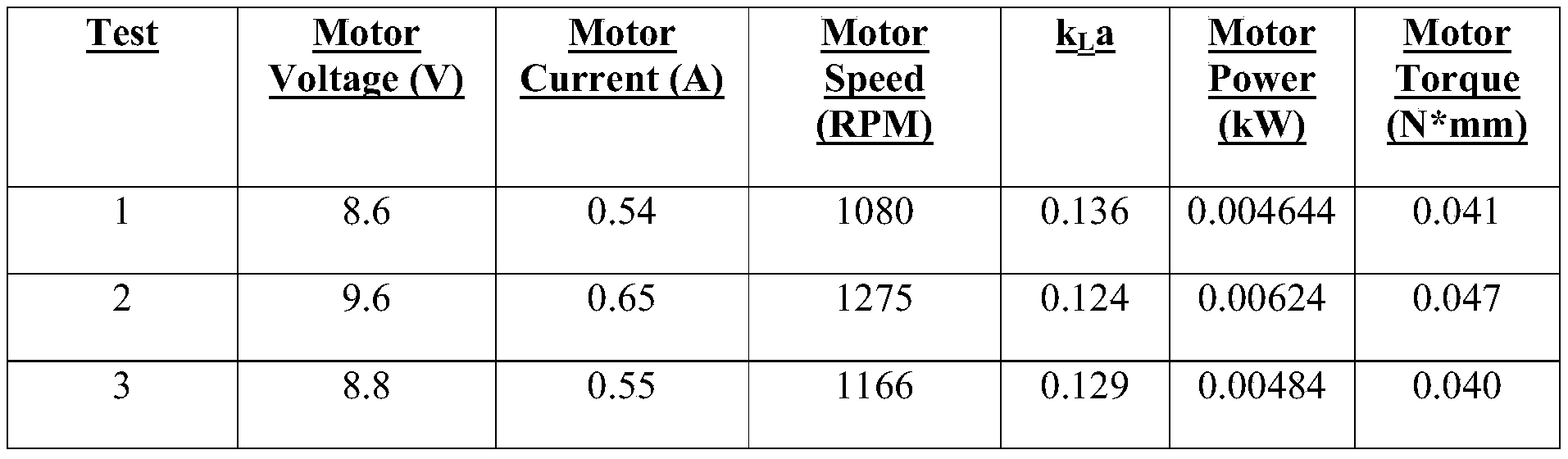
- Mixing of a gas and a liquid can also be evaluated by considering a power of a motor driving an agitator.
- a lower amount of motor power allows for use of a smaller motor.
- a smaller motor can allow for a smaller overall carbonation system and/or can free space for other components in the carbonation system that includes the motor.
- achieving a high k L a while minimizing motor power generally provides efficient mixing of a gas and a liquid to form a carbonated fluid while allowing for use of a smaller motor.
- Table 1 shows three tests 1, 2, 3 of various motor settings of voltage, current, speed, power, and torque and the corresponding k L a.
- the tests 1, 2, 3 were performed using an agitator similar to the agitator 10 of FIGS. 1-7 and using a BLDC motor allowing for contactless magnetic drive system similar to the motors 500, 700 of FIGS. 17 and 19.
Landscapes
- Chemical & Material Sciences (AREA)
- Chemical Kinetics & Catalysis (AREA)
- Health & Medical Sciences (AREA)
- Nutrition Science (AREA)
- Life Sciences & Earth Sciences (AREA)
- Engineering & Computer Science (AREA)
- Food Science & Technology (AREA)
- Polymers & Plastics (AREA)
- Accessories For Mixers (AREA)
- Mixers Of The Rotary Stirring Type (AREA)
Abstract
Description
Claims (46)
- A system, comprising:a chamber configured to receive liquid from a liquid source and gas from a gas source; andan agitator disposed within the chamber and having an elongate shaft and having a plurality of arms extending radially outward from the elongate shaft, each of the plurality of arms having an angled outer tip;wherein, when the chamber contains the liquid and the gas and the agitator is partially disposed within the liquid, the agitator is configured to be rotated by the motor to mix the gas and the liquid.
- The system of claim 1, wherein each of the plurality of arms extends from the elongate shaft substantially perpendicular to a longitudinal axis of the elongate shaft.
- The system of claim 2, wherein the outer tip of each of the plurality of arms is at an acute angle relative to the longitudinal axis of the elongate shaft.
- The system of claim 1, wherein each of the plurality of arms has a paddle shape.
- The system of claim 1, wherein the elongate shaft of the agitator has at least one inner lumen extending therethrough between an upper opening and a lower opening;the arms are positioned adjacent to the lower opening; andwhen the chamber contains the liquid and the gas and the agitator is partially disposed within the liquid and is rotated by the motor to mix the gas and the liquid, the gas above the liquid is configured to flow into the upper opening of the elongate shaft, through the at least one inner lumen of the elongate shaft, and out the lower opening such that the gas exiting the lower opening reencounters the liquid.
- The system of claim 1, wherein an outer edge of each of the arms is defined by a plurality of fingers that extend radially outward and are configured to allow the gas to pass between adjacent ones of the fingers during the rotation of the agitator.
- The system of claim 1, wherein an outer edge of each of the arms is a continuous substantially planar edge.
- The system of claim 1, further comprising a motor coupled to the agitator and configured to rotatably drive the agitator;wherein the motor includes a stator and a rotor.
- The system of claim 8, wherein the rotor includes a plastic magnet.
- The system of claim 8, wherein the agitator is magnetically coupled to the motor.
- The system of claim 8, wherein the agitator is physically coupled to a first portion of the motor; andthe first portion of the motor is magnetically coupled to a second portion of the motor.
- The system of claim 11, wherein the first portion includes the rotor, and the second portion includes the stator.
- The system of claim 8, wherein the agitator and the rotor are disposed inside the chamber, and the stator is disposed external to the chamber.
- The system of claim 13, wherein the rotor includes a first magnet, the agitator includes a second magnet, and rotation of the rotor is configured to drive the rotation of the agitator through interaction of the second magnet with the first magnet.
- The system of claim 14, wherein the agitator includes an upper housing that houses the second magnet and is located adjacent to the rotor.
- The system of claim 13, wherein a wall of the chamber separates the rotor and the stator.
- The system of claim 13, further comprising a bushing that separates the rotor and the stator.
- The system of claim 8, wherein the agitator is disposed inside the chamber, and the stator and the rotor are disposed external to the chamber.
- An agitator for use in a carbonation mixing apparatus, comprising:a rotatable elongate shaft having an upper end and a lower end; anda plurality of arms extending radially outward from the elongate shaft relative to a longitudinal axis of the elongate shaft, the plurality of arms being positioned adjacent to the lower end of the elongate shaft, wherein each of the arms includes a first portion proximate the elongate shaft and a second portion that is radially outward from the first portion and from the elongate shaft, the first portion extending at a first angle relative to the longitudinal axis of the elongate shaft, and the second portion extending at a second, different angle relative to the longitudinal axis such that each of the arms has an angled outer tip.
- The agitator of claim 19, wherein the first portion of each of the plurality of arms is substantially perpendicular to the longitudinal axis of the elongate shaft.
- The agitator of claim 20, wherein the second portion of each of the plurality of arms is at an acute angle relative to the first portion.
- The agitator of claim 19, wherein the first and second portions of each of the plurality of arms define a paddle shape of the arm.
- The agitator of claim 19, wherein the second portion of each of the arms includes a plurality of fingers that extend radially outward and are configured to allow a gas to pass between adjacent ones of the fingers during rotation of the agitator.
- The agitator of claim 19, wherein an outer edge of the second portion of each of the arms is a continuous substantially planar edge.
- The agitator of claim 19, further comprising a flange extending radially outward from the elongate shaft, each of the arms being located at least partially below the flange.
- The agitator of claim 25, wherein the first portion of each arm abuts a surface of the flange.
- The agitator of claim 19, further comprising at least one inner lumen extending through the elongate shaft and having an upper opening and a lower opening.
- The agitator of claim 27, wherein the plurality of arms are positioned adjacent to the lower opening.
- The agitator of claim 27, further comprising a central bore extending through the elongate shaft;wherein the at least one inner lumen is positioned radially outward of the central bore.
- The agitator of claim 27, wherein the at least one inner lumen comprises first and second inner lumens.
- The agitator of claim 19, wherein the elongate shaft has a cavity extending therethrough, and the cavity has an upper opening at the upper end and a lower opening at the lower end.
- The agitator of claim 31, wherein the cavity includes a central bore extending along the longitudinal axis of the elongate shaft and includes at least one lumen positioned radially outward of the central bore, the at least one lumen including the upper opening and the lower opening.
- The agitator of claim 32, wherein the at least one inner lumen comprises first and second inner lumens surrounding the central bore.
- The agitator of claim 19, further comprising a central bore extending through the elongate shaft.
- The agitator of claim 19, wherein the elongate shaft and the plurality of arms are configured to rotate about the longitudinal axis of the elongate shaft.
- The agitator of claim 19, wherein the elongate shaft is configured to be operably coupled to a motor configured to drive rotation of the agitator.
- A method, comprising:activating a motor and thereby driving rotation of an agitator disposed within in a sealed chamber having liquid and gas therein such that the gas mixes with the liquid in the chamber to form a carbonated fluid;wherein the agitator includes a plurality of arms extending radially outward at a first angle relative to a longitudinal axis of the elongate shaft;each of the plurality of arms has an outer tip extending at a second, different angle relative to the longitudinal axis of the elongate shaft; andthe plurality of arms are configured to encourage the mixing of the gas and the liquid.
- The method of claim 37, wherein gas located above the liquid flows into an upper opening in an elongate shaft of the agitator and out of a lower opening of the elongate shaft of the agitator such that the gas mixes with the liquid in the chamber to form the carbonated fluid.
- The method of claim 37, wherein the first angle is substantially 90°.
- The method of claim 39, wherein the second angle is an acute angle.
- The method of claim 37, wherein the motor includes a stator and a rotor, the agitator and the rotor are disposed inside the chamber, and the stator is disposed external to the chamber.
- The method of claim 37, wherein the motor drives the rotation of the agitator through interaction of a first magnet of the motor with a second magnet of the agitator.
- The method of claim 37, wherein the motor drives the rotation of the agitator by causing rotation of a drive rod that is operably coupled to the agitator.
- The method of claim 37, wherein the gas repeatedly flows into an upper opening of an elongate shaft of the agitator and out of a lower opening of the elongate shaft so as to circulate in the chamber.
- The method of claim 37, further comprising dispensing, with a dispensing system, the carbonated fluid into a container for a user.
- The method of claim 37, wherein the gas is carbon dioxide, and the liquid is water.
Priority Applications (6)
| Application Number | Priority Date | Filing Date | Title |
|---|---|---|---|
| EP22941185.5A EP4521953A1 (en) | 2022-05-13 | 2022-05-13 | Agitator for a carbonation system |
| CA3253404A CA3253404A1 (en) | 2022-05-13 | 2022-05-13 | Agitator for a carbonation system |
| CN202280097246.8A CN119403454A (en) | 2022-05-13 | 2022-05-13 | Agitators for carbonation systems |
| PCT/CN2022/092688 WO2023216231A1 (en) | 2022-05-13 | 2022-05-13 | Agitator for a carbonation system |
| AU2022457789A AU2022457789A1 (en) | 2022-05-13 | 2022-05-13 | Agitator for a carbonation system |
| US17/843,078 US11612865B1 (en) | 2022-05-13 | 2022-06-17 | Agitator for a carbonation system |
Applications Claiming Priority (1)
| Application Number | Priority Date | Filing Date | Title |
|---|---|---|---|
| PCT/CN2022/092688 WO2023216231A1 (en) | 2022-05-13 | 2022-05-13 | Agitator for a carbonation system |
Related Child Applications (1)
| Application Number | Title | Priority Date | Filing Date |
|---|---|---|---|
| US17/843,078 Continuation US11612865B1 (en) | 2022-05-13 | 2022-06-17 | Agitator for a carbonation system |
Publications (1)
| Publication Number | Publication Date |
|---|---|
| WO2023216231A1 true WO2023216231A1 (en) | 2023-11-16 |
Family
ID=85722531
Family Applications (1)
| Application Number | Title | Priority Date | Filing Date |
|---|---|---|---|
| PCT/CN2022/092688 Ceased WO2023216231A1 (en) | 2022-05-13 | 2022-05-13 | Agitator for a carbonation system |
Country Status (6)
| Country | Link |
|---|---|
| US (1) | US11612865B1 (en) |
| EP (1) | EP4521953A1 (en) |
| CN (1) | CN119403454A (en) |
| AU (1) | AU2022457789A1 (en) |
| CA (1) | CA3253404A1 (en) |
| WO (1) | WO2023216231A1 (en) |
Families Citing this family (4)
| Publication number | Priority date | Publication date | Assignee | Title |
|---|---|---|---|---|
| CN116689119B (en) * | 2023-06-09 | 2025-11-14 | 江苏吉达机械制造有限公司 | Segmented grinding and separate sorting grinding system |
| WO2024254851A1 (en) * | 2023-06-16 | 2024-12-19 | Sharkninja Operating Llc | Carbonation chamber |
| US20250128213A1 (en) | 2023-10-24 | 2025-04-24 | Sharkninja Operating Llc | Ratchet system for a gas canister in a beverage system |
| US20250161889A1 (en) | 2023-11-21 | 2025-05-22 | Sharkninja Operating Llc | Multi-purpose valve for a beverage system |
Citations (10)
| Publication number | Priority date | Publication date | Assignee | Title |
|---|---|---|---|---|
| CN85203333U (en) * | 1985-08-15 | 1986-06-18 | 吉林化工学院 | Hollow shaft stirrer |
| JP2001261713A (en) * | 2000-03-21 | 2001-09-26 | Mitsubishi Rayon Co Ltd | Stirrer and method for producing polymer using the same |
| JP2006289221A (en) * | 2005-04-08 | 2006-10-26 | Kansai Paint Co Ltd | Paddle blade and stirring device provided with the paddle blade |
| CN201451258U (en) * | 2009-07-16 | 2010-05-12 | 陈文洲 | Carbonated water producing device |
| CN101811004A (en) * | 2009-09-09 | 2010-08-25 | 威海化工机械有限公司 | High efficient self-absorbing type stirrer |
| CN102233245A (en) * | 2011-07-13 | 2011-11-09 | 浙江长江搅拌设备有限公司 | Gas, solid and liquid stirring machine with high-efficiency flexible structure |
| CN104772083A (en) * | 2015-03-18 | 2015-07-15 | 四川中哲新材料科技有限公司 | Gas-liquid mixing and stirring device |
| CN108211867A (en) * | 2018-02-26 | 2018-06-29 | 北京百正创源科技有限公司 | Blender and the equipment with the blender |
| CN109954471A (en) * | 2017-12-26 | 2019-07-02 | 沈阳东瑞精细化工有限公司 | Self-priming sulbactam hydrogenation equipment |
| CN111215015A (en) * | 2019-12-26 | 2020-06-02 | 浙江长城搅拌设备股份有限公司 | Special stirring device for viscous fluid mixing and gas dispersing |
Family Cites Families (346)
| Publication number | Priority date | Publication date | Assignee | Title |
|---|---|---|---|---|
| US1123092A (en) * | 1914-02-18 | 1914-12-29 | George Calvert | Apparatus for mixing gases and liquids. |
| US1242493A (en) | 1917-01-12 | 1917-10-09 | Richard H Stringham | Electrical drink-mixer. |
| US1420773A (en) | 1921-12-22 | 1922-06-27 | Magnetic Drink Mixer Company | Electrical drink mixer |
| US2350534A (en) * | 1942-10-05 | 1944-06-06 | Rosinger Arthur | Magnetic stirrer |
| US2566743A (en) * | 1949-10-24 | 1951-09-04 | Okulitch George Joseph | Magnetic drive agitator |
| US2917372A (en) * | 1958-09-12 | 1959-12-15 | Sun Oil Co | Liquid-gas contact reactor |
| US3108146A (en) * | 1959-09-16 | 1963-10-22 | George E Gross | Fluid handling device |
| DE1557138B2 (en) * | 1966-02-10 | 1973-08-23 | Metallgesellschaft AG, 6000 Frank fürt | DEVICE FOR GASIFYING LIQUIDS |
| PT68320A (en) | 1977-07-29 | 1978-08-01 | Sodastream Ltd | Portable apparatus for carbonating water |
| ZA835729B (en) | 1982-08-20 | 1984-09-26 | Sodastream Ltd | Liquid aerating apparatus |
| CH668919A5 (en) | 1984-05-07 | 1989-02-15 | Dieter Alex Rufer | DEVICE FOR STIRING OR PUMPING A MEDIUM. |
| CN1016312B (en) | 1985-07-26 | 1992-04-22 | 伊索沃思有限公司 | Water carbonating equipment for preparing small amount of drink |
| US4866324A (en) | 1987-04-28 | 1989-09-12 | Canon Kabushiki Kaisha | Brushless motor |
| US5128574A (en) | 1989-04-11 | 1992-07-07 | Canon Kabushiki Kaisha | Brushless motor |
| US5038976A (en) | 1989-11-08 | 1991-08-13 | Imi Cornelius Inc. | Method of and dispensing head for increased carbonation |
| EP0470493B1 (en) * | 1990-08-07 | 1996-09-25 | Shinko Pantec Co., Ltd. | Mixing apparatus |
| US5156871A (en) | 1991-05-01 | 1992-10-20 | Imi Cornelius Inc. | Low cost beverage carbonating apparatus and method |
| US5407271A (en) * | 1993-10-07 | 1995-04-18 | Jorgen Jorgensen Maskinfabrik A/S | Integrated rotary mixer and disperser head |
| IL119044A (en) | 1996-08-08 | 2004-09-27 | Shemuel Amitai | Water carbonating device |
| ID29872A (en) | 1999-01-12 | 2001-10-18 | Island Oasis Frozen Cocktail C | FOOD PROCESSING TOOLS WITH MAGNETIC MOVEMENT |
| US6095677A (en) | 1999-01-12 | 2000-08-01 | Island Oasis Frozen Cocktail Co., Inc. | Magnetic drive blender |
| GB9914595D0 (en) | 1999-06-22 | 1999-08-25 | Atchinson Investments Limited | Water carbonator |
| DE20101093U1 (en) | 2001-01-17 | 2002-05-29 | DS Produkte Dieter Schwarz GmbH, 22145 Hamburg | Device for enriching a drink with gas |
| US7418899B2 (en) | 2001-02-08 | 2008-09-02 | Kraft Foods R & D, Inc. | Cartridge for the preparation of beverages |
| US6672481B2 (en) | 2001-02-22 | 2004-01-06 | The Coca-Cola Company | On demand carbonation system |
| CZ20032681A3 (en) | 2001-04-06 | 2004-03-17 | Scott Nicol | Apparatus for carbonation and water carbonation process |
| JP2003033635A (en) * | 2001-05-17 | 2003-02-04 | Shinko Pantec Co Ltd | Stirring blade, stirring device and stirring method using the same |
| WO2002096761A2 (en) | 2001-05-22 | 2002-12-05 | Shurflo Pump Manufacturing Company, Inc. | Appliance and an appliance drive unit |
| US6652893B2 (en) | 2001-07-09 | 2003-11-25 | William Berson | Machine and process for aerating and flavoring water |
| GB0200476D0 (en) * | 2002-01-10 | 2002-02-27 | Univ Aston | Reactor |
| FR2839825B1 (en) | 2002-05-17 | 2004-08-06 | Seb Sa | ELECTRIC MOTOR FOR HOUSEHOLD APPLIANCE FOR FOOD PREPARATION |
| US9751054B2 (en) | 2002-06-08 | 2017-09-05 | Ucc Ueshima Coffee Co., Ltd. | Milk foamer |
| US7533603B2 (en) | 2003-01-24 | 2009-05-19 | Kraft Foods R & D, Inc. | Cartridge for the preparation of beverages |
| US7231869B2 (en) | 2003-01-24 | 2007-06-19 | Kraft Foods R & D Inc. | Machine for the preparation of beverages |
| US7592027B2 (en) | 2003-01-24 | 2009-09-22 | Kraft Foods R & D, Inc. | Method for the preparation of beverages |
| US7255039B2 (en) | 2003-01-24 | 2007-08-14 | Kraft Foods R & D, Inc. | Machine for the preparation of beverages |
| US7533604B2 (en) | 2003-01-24 | 2009-05-19 | Kraft Foods R & D, Inc. | Cartridge system for the preparation of beverages and method of manufacturing said system |
| US7287461B2 (en) | 2003-01-24 | 2007-10-30 | Kraft Foods R & D, Inc. | Cartridge for the preparation of beverages |
| US7213506B2 (en) | 2003-01-24 | 2007-05-08 | Kraft Foods R & D, Inc. | Cartridge for the preparation of beverages |
| US7219598B2 (en) | 2003-01-24 | 2007-05-22 | Kraft Foods R & D, Inc. | Cartridge for the preparation of beverages |
| US7322277B2 (en) | 2003-01-24 | 2008-01-29 | Kraft Foods R & D, Inc. | Cartridge and method for the preparation of beverages |
| US7316178B2 (en) | 2003-01-24 | 2008-01-08 | Kraft Foods R & D, Inc. | Machine for the preparation of beverages |
| US7097074B2 (en) | 2003-01-24 | 2006-08-29 | Kraft Foods R&D, Inc. | Machine for the preparation of beverages |
| US7607385B2 (en) | 2003-01-24 | 2009-10-27 | Kraft Foods R & D, Inc. | Machine for the preparation of beverages |
| US7445133B2 (en) | 2003-10-12 | 2008-11-04 | Daniel Ludovissie | Multiple beverage and flavor additive beverage dispenser |
| US7614524B2 (en) | 2004-02-13 | 2009-11-10 | Intelligent Coffee Company, Llc | Liquid concentrate/extract beverage dispenser with replaceable concentrate/extract cartridge |
| DE102004007727A1 (en) | 2004-02-16 | 2005-09-01 | Margret Spiegel | Conventional carbonator systems or impregnation systems in addition at least one hollow body inline impregnator filled with bulk material to nachkarbonisieren or impregnate already carbonated or impregnated liquids |
| GB2413480B (en) | 2004-02-17 | 2006-08-30 | Kraft Foods R & D Inc | An insert and a system for the preparation of beverages |
| GB2411105B (en) | 2004-02-17 | 2006-08-30 | Kraft Foods R & D Inc | An insert and a system for the preparation of beverages |
| EP1579793B1 (en) | 2004-03-26 | 2007-07-11 | ILLYCAFFE' S.p.A. | Beverage extraction assembly for extracting a beverage from a particulate substance contained in a cartridge |
| US7828175B2 (en) | 2004-05-21 | 2010-11-09 | Pepsico, Inc. | Beverage dispensing system with a head capable of dispensing plural different beverages |
| US8556127B2 (en) | 2004-05-24 | 2013-10-15 | Pur Water Purification Products, Inc. | Additive dispensing system for a refrigerator |
| US8893927B2 (en) | 2004-05-24 | 2014-11-25 | Pur Water Purification Products, Inc. | Cartridge for an additive dispensing system |
| EP1642637A1 (en) | 2004-09-29 | 2006-04-05 | Soda-Club Ltd | A device for carbonating a liquid with pressurized gas |
| EP1656866A1 (en) | 2004-11-12 | 2006-05-17 | Nestec S.A. | Device and method for the preparation of froth from a liquid milk-based food product |
| US7472643B2 (en) | 2004-12-31 | 2009-01-06 | Whirlpool Corporation | Disposable flavor insert for water dispenser |
| US7507430B2 (en) | 2005-06-10 | 2009-03-24 | Concordia Coffee Company, Inc. | Method for preparing a heated flavored beverage |
| DE102005045157A1 (en) | 2005-09-21 | 2007-03-29 | Friedhelm Selbach Gmbh | Process for the carbonation of water in a beverage dispenser and arrangement for mixing CO2 with water |
| DK1767467T3 (en) | 2005-09-21 | 2009-08-10 | Illycaffe Spa | Insert containing a substance for extracting a beverage |
| EP2653439A1 (en) | 2005-11-04 | 2013-10-23 | The Coca-Cola Company | Systems and methods for dispensing flavor doses and blended beverages |
| US8960500B2 (en) | 2006-03-06 | 2015-02-24 | The Coca-Cola Company | Dispenser for beverages including juices |
| WO2008049001A2 (en) | 2006-10-17 | 2008-04-24 | Mks Intruments, Inc. | Devices, systems, and methods for carbonation of deionized water |
| US20110020508A1 (en) | 2007-04-05 | 2011-01-27 | Rising Phoenix Co. | Select Serving and Flavored Sparkling Beverage Maker |
| US8677888B2 (en) | 2007-04-05 | 2014-03-25 | Primo Products, LLC | Select serving and flavored sparkling beverage maker |
| GB2449213B (en) | 2007-05-18 | 2011-06-29 | Kraft Foods R & D Inc | Improvements in or relating to beverage preparation machines and beverage cartridges |
| CA2686464C (en) | 2007-05-23 | 2015-06-30 | Nestec S.A. | Appliance for conditioning a milk-based liquid |
| MX2010002219A (en) | 2007-09-06 | 2010-04-27 | Coca Cola Co | Method for consumer-dispenser interactions. |
| ATE503410T1 (en) | 2007-11-05 | 2011-04-15 | Pi Design Ag | MILK FROTHER WITH IMPROVED FOAMING EFFECT |
| DE102007063549A1 (en) | 2007-12-21 | 2009-06-25 | Eldora Gmbh | Automatic milk frother |
| US8685477B2 (en) | 2008-01-17 | 2014-04-01 | Enodis Corporation | Method for blending a beverage in a single serving cup |
| US9044718B2 (en) | 2008-03-19 | 2015-06-02 | Sartorius Stedim Biotech Gmbh | Mixing vessel |
| US8403179B1 (en) | 2008-04-14 | 2013-03-26 | Flavor Burst Co., L.L.P. | Automatic draw valve freezer with multiple flavor option |
| FR2930883B1 (en) | 2008-05-07 | 2013-03-22 | Cie Mediterraneenne Des Cafes | MOUSSEUR FOR PREPARING FOAM FROM A BEVERAGE COMPRISING MILK |
| JP5248190B2 (en) | 2008-05-09 | 2013-07-31 | ザ コカ・コーラ カンパニー | Beverage dispenser |
| CN201200323Y (en) | 2008-05-12 | 2009-03-04 | 蔡坚明 | Kettle for heating, stirring and foaming milk |
| DE102008025508A1 (en) | 2008-05-28 | 2009-12-03 | Sartorius Stedim Biotech Gmbh | mixing system |
| US9272827B2 (en) | 2008-08-29 | 2016-03-01 | Pepsico, Inc. | Post-mix beverage system |
| WO2010077698A1 (en) | 2008-12-08 | 2010-07-08 | Enodis Corporation | An integrated method and system for dispensing and blending/mixing beverage ingredients |
| US8468935B2 (en) | 2008-12-18 | 2013-06-25 | Whirlpool Corporation | Liquid flow control and beverage preparation apparatuses, methods and systems |
| US8282268B2 (en) | 2009-02-24 | 2012-10-09 | Island Oasis Frozen Cocktail Co., Inc. | Magnetic drive for food processing apparatus |
| GB2469873B (en) | 2009-05-01 | 2011-09-07 | Kraft Foods R & D Inc | Beverage preparation machines |
| IT1396897B1 (en) | 2009-11-20 | 2012-12-20 | Espressocap Srl | DEVICE FOR THE PRODUCTION OF MILK OR SIMILAR FOAM. |
| US8490829B2 (en) | 2009-11-24 | 2013-07-23 | Pepsico, Inc. | Personalized beverage dispensing device |
| US8335592B2 (en) | 2009-11-24 | 2012-12-18 | Pepsico, Inc. | Beverage dispensing device |
| US9754437B2 (en) | 2009-11-24 | 2017-09-05 | Pepsico, Inc. | Automated beverage formulation |
| WO2011088329A2 (en) | 2010-01-14 | 2011-07-21 | Bevtech, Inc. | Co2 system pressure control valve |
| KR20120134118A (en) | 2010-02-01 | 2012-12-11 | 그린 마운틴 커피 로스터스, 인크. | Method and apparatus for cartridge-based carbonation of beverages |
| US9936834B2 (en) | 2010-02-01 | 2018-04-10 | Bedford Systems Llc | Method and apparatus for cartridge-based carbonation of beverages |
| EP2353469A1 (en) | 2010-02-03 | 2011-08-10 | Nestec S.A. | Beverage preparation machine for large size beverages |
| US10000370B2 (en) | 2010-02-05 | 2018-06-19 | Ecowell, Llc | Container-less custom beverage vending invention |
| US8442674B2 (en) | 2010-02-05 | 2013-05-14 | Ecowell | Container-less custom beverage vending invention |
| US10017372B2 (en) | 2010-02-05 | 2018-07-10 | Ecowell, Llc | Container-less custom beverage vending invention |
| FI122387B (en) | 2010-02-23 | 2011-12-30 | Outotec Oyj | Flotation |
| US20150125586A1 (en) | 2010-05-03 | 2015-05-07 | Apiqe | Beverage system with flavor pod dispenser |
| CN102255402B (en) | 2010-05-20 | 2016-01-20 | 德昌电机(深圳)有限公司 | Household electrical appliance |
| CN102247101B (en) | 2010-05-21 | 2015-07-22 | 德昌电机(深圳)有限公司 | Kitchen appliance |
| IT1400491B1 (en) | 2010-06-03 | 2013-06-11 | De Longhi Appliances Srl | APPLIANCES FOR THE TREATMENT OF A FOOD LIQUID |
| US8840092B2 (en) | 2010-06-29 | 2014-09-23 | Cornelius, Inc. | Carbonation apparatus and method for forming a carbonated beverage |
| RU2555787C2 (en) | 2010-07-14 | 2015-07-10 | МДС Глобал Холдинг п.л.к. | Drink preparing and dispensing system and method |
| CN102958408B (en) | 2010-07-14 | 2016-08-24 | 荷兰联合利华有限公司 | For the method for beverage brewed with comprise can the storage box of soak-out material |
| PT3521208T (en) | 2010-07-22 | 2020-05-21 | K Fee System Gmbh | Portion capsule with barcode |
| GB201014663D0 (en) | 2010-09-03 | 2010-10-20 | Gort Barten Alex | Milk frother |
| CN103153143B (en) | 2010-10-08 | 2016-08-24 | 皇家飞利浦电子股份有限公司 | There is the infusion unit of horizontal movement |
| US20120114814A1 (en) | 2010-11-05 | 2012-05-10 | The Coca-Cola Company | Method of beverage production, apparatus and system |
| WO2012064885A1 (en) | 2010-11-09 | 2012-05-18 | Adg Development Llc | Capsule based system for preparing and dispensing a beverage |
| EP2992792B1 (en) | 2010-11-11 | 2017-03-15 | Nestec S.A. | Beverage production machine and rinsing and/or descaling insert |
| MX2013007770A (en) | 2011-01-03 | 2013-08-21 | Nestec Sa | Motorized beverage machine with mecanical transmission. |
| CA2830781A1 (en) | 2011-03-23 | 2012-09-27 | Imi Cornelius, Inc. | Hot/cold beverage dispenser and method |
| US8746506B2 (en) | 2011-05-26 | 2014-06-10 | Pepsico, Inc. | Multi-tower modular dispensing system |
| US8985396B2 (en) | 2011-05-26 | 2015-03-24 | Pepsico. Inc. | Modular dispensing system |
| EP2714252B1 (en) | 2011-06-03 | 2018-04-11 | Breville Pty Limited | Carbonation device |
| TW201311198A (en) | 2011-06-16 | 2013-03-16 | Green Mountain Coffee Roasters Inc | Compositions, systems and methods for portion-packaged soups and meals |
| EP2543290A1 (en) | 2011-07-08 | 2013-01-09 | Koninklijke Philips Electronics N.V. | Brewing unit with a water heater |
| JP6129834B2 (en) | 2011-08-03 | 2017-05-17 | キューリグ グリーン マウンテン インク | Method and apparatus for cartridge-type carbonate saturation of beverages |
| LT3040114T (en) | 2011-08-10 | 2019-07-25 | Sodastream Industries Ltd. | HOUSEHOLD CARBONIZATION MECHANISM |
| EP2782485B1 (en) | 2011-09-09 | 2018-10-24 | Fountain Master, LLC | Beverage maker |
| US10455848B2 (en) | 2011-10-05 | 2019-10-29 | Island Oasis Frozen Cocktail Company, Inc. | Individual frozen drink dispenser |
| US10080459B2 (en) | 2011-11-09 | 2018-09-25 | La Vit Technology Llc | Capsule-based system for preparing and dispensing a beverage |
| AU2013226166B2 (en) | 2012-02-28 | 2018-03-08 | Gudpod Corp. | A nutraceutical compounding system and method therefore |
| US9161654B2 (en) | 2012-03-09 | 2015-10-20 | Primo Products Llc | Select serving and flavored sparkling beverage maker system |
| US20130340626A1 (en) | 2012-06-22 | 2013-12-26 | Touch Coffee and Beverages, LLC. | Beverage brewing system |
| US8985561B2 (en) | 2012-06-29 | 2015-03-24 | Bonne O Inc. | Beverage carbonating system and method for carbonating a beverage |
| JP5857157B2 (en) | 2012-07-12 | 2016-02-10 | コーニンクレッカ フィリップス エヌ ヴェKoninklijke Philips N.V. | Equipment for stirring liquid food products |
| US9700852B2 (en) | 2012-08-28 | 2017-07-11 | So Spark Ltd. | System, method and capsules for producing sparkling drinks |
| EP2892639B1 (en) | 2012-09-10 | 2019-01-16 | Top Electrical Appliances Industrial Co. Ltd. | A liquid stirring apparatus |
| IN2015MN00024A (en) | 2012-09-13 | 2015-10-16 | Strauss Water Ltd | |
| US9375686B2 (en) | 2012-10-10 | 2016-06-28 | Whirlpool Corporation | Apparatus, method and systems for providing selectable level carbonated water |
| ITTO20120930A1 (en) | 2012-10-23 | 2014-04-24 | Bruno Pirone | ADDITIVATION DEVICE FOR DRINKS AND ASSOCIATED METHOD. |
| PL2925638T3 (en) | 2012-11-29 | 2017-05-31 | Nestec S.A. | Capsule for preparing a beverage or nutritional product |
| DE202012104659U1 (en) | 2012-11-30 | 2014-03-05 | Wik Far East Ltd. | Electrical device for treating a liquid-based foodstuff, in particular for frothing it |
| US10919752B2 (en) | 2012-12-19 | 2021-02-16 | Michael John Breault | Refrigerator with carbonated drink spout |
| EP2935088A4 (en) | 2012-12-19 | 2017-01-04 | S.L. Sprizzi Europe | Beverage dispenser and related methods |
| US10028614B2 (en) | 2012-12-21 | 2018-07-24 | Nestec S.A. | Device for producing milk foam |
| US9114368B2 (en) | 2013-03-08 | 2015-08-25 | Cornelius, Inc. | Batch carbonator and method of forming a carbonated beverage |
| US8960078B2 (en) | 2013-03-14 | 2015-02-24 | Keurig Green Mountain, Inc. | Reusable beverage cartridge |
| US9440836B2 (en) | 2013-03-14 | 2016-09-13 | The Coca-Cola Company | Rotary cabonator |
| US20140263406A1 (en) | 2013-03-14 | 2014-09-18 | The Coca-Cola Company | Beverage Dispenser with Integrated Carbonator and a Potable Water/Ice Slurry Refrigeration System |
| CA2906075A1 (en) | 2013-03-14 | 2014-10-02 | Pepsico, Inc. | Micro dosing dispensing system |
| US9216887B2 (en) | 2013-03-15 | 2015-12-22 | The Coca-Cola Company | Efficiently and easily opening and closing a canister valve |
| US8906436B2 (en) | 2013-03-15 | 2014-12-09 | Ptc-Innovations, Llc | Single serve beverage additive cartridge |
| US9718035B2 (en) | 2013-04-11 | 2017-08-01 | Bunn-O-Matic Corporation | Carbonator system, method and apparatus |
| WO2014182423A2 (en) | 2013-05-10 | 2014-11-13 | Juicero, Inc. | Juicing systems and methods |
| US9107448B2 (en) | 2013-06-03 | 2015-08-18 | Cornelius, Inc. | Method for carbonating a beverage |
| US9630826B2 (en) | 2013-06-07 | 2017-04-25 | The Coca-Cola Company | Beverage making machine |
| US20140154368A1 (en) | 2013-06-07 | 2014-06-05 | The Coca-Cola Company | Beverage Making Cartridges for Use in a Beverage Making Machine |
| US9233824B2 (en) | 2013-06-07 | 2016-01-12 | The Coca-Cola Company | Method of making a beverage including a gas in a beverage making machine |
| US9107449B2 (en) | 2013-06-05 | 2015-08-18 | Cornelius, Inc. | Method for customizing a beverage's carbonation level |
| CN203314745U (en) | 2013-06-18 | 2013-12-04 | 利尔达科技集团股份有限公司 | Soybean milk machine based on brushless direct current motor |
| WO2014201753A1 (en) | 2013-06-21 | 2014-12-24 | Xiong Xingjian | Milk foaming machine |
| EP3021686A4 (en) | 2013-07-18 | 2017-02-08 | SodaStream Industries Ltd. | Device for dispensing carbonated water |
| SI3033296T1 (en) | 2013-08-12 | 2019-08-30 | Sodastream Industries Ltd. | Burst disk protected valve |
| CN105517470B (en) | 2013-08-13 | 2020-10-23 | 皇家飞利浦有限公司 | Coffee machine for providing coffee brew with reduced caffeine content |
| WO2015031515A1 (en) | 2013-08-27 | 2015-03-05 | Feola Anthony V | Frozen confection machine |
| CN203576299U (en) | 2013-11-06 | 2014-05-07 | 熊兴剑 | Milk foaming machine |
| GB201321295D0 (en) | 2013-12-03 | 2014-01-15 | Hodges & Drake Design Ltd | Apparatus for dispensing a flavour alcoholic beverage |
| US20150351436A1 (en) | 2014-06-05 | 2015-12-10 | Jb Scientific, Llc | Affecting enjoyment of food |
| DE102013224786B3 (en) | 2013-12-03 | 2015-03-12 | Wmf Ag | Milk frothing device with dynamic mixing unit and beverage maker containing the same |
| CN103720363B (en) | 2013-12-20 | 2015-11-18 | 宁波瑞易电器科技发展有限公司 | There is the Soda water machine of inspissated juice powder ink discharge device |
| EP3086693B1 (en) | 2013-12-23 | 2021-02-17 | The Coca-Cola Company | Dispensing ingredients from a beverage cartridge |
| US9521924B2 (en) | 2013-12-24 | 2016-12-20 | Pangaea Labs Ltd. | Brewable beverage making machine |
| TWI527549B (en) | 2014-04-18 | 2016-04-01 | 吉川實業有限公司 | Carbonated beverage manufacturing method and carbonated beverage manufacturing machine therefor |
| MX2016014115A (en) | 2014-04-30 | 2017-02-09 | Coca Cola Co | A dispensing system. |
| US10405690B2 (en) | 2014-06-19 | 2019-09-10 | Massimo Tentorio | Single serve brewing machine |
| WO2015198233A1 (en) | 2014-06-24 | 2015-12-30 | Sodastream Industries Ltd. | Automatic release of pressure in a home soda machine |
| WO2016016743A1 (en) | 2014-07-31 | 2016-02-04 | Carimali S.P.A. | A device for frothing milk |
| CA2959445C (en) | 2014-08-28 | 2023-03-07 | Tbot Inc. | Systems and methods for automated dispensing |
| US9327900B2 (en) | 2014-09-09 | 2016-05-03 | Keurig Green Mountain, Inc. | Method and apparatus for cartridge-based carbonation of beverages |
| EP3000780A1 (en) | 2014-09-26 | 2016-03-30 | Anheuser-Busch InBev S.A. | Beverage dispensing assembly comprising an ingedient container receiving means and a gas pressure regulator |
| EP3000779A1 (en) | 2014-09-26 | 2016-03-30 | Anheuser-Busch InBev S.A. | Beverage dispensing device comprising at least two pod or capsule receiving means |
| HRP20210475T1 (en) | 2014-09-30 | 2021-05-14 | Sodastream Industries Ltd. | Carbonation machine |
| CA3207639A1 (en) | 2014-10-20 | 2016-04-28 | Bedford Systems Llc | Cartridge holder for beverage machine |
| US10051988B2 (en) | 2014-10-20 | 2018-08-21 | Bedford Systems Llc | Mixing chamber for beverage machine |
| CA2965136A1 (en) | 2014-10-20 | 2016-04-28 | Bedford Systems Llc | Flow circuit for carbonated beverage machine |
| US10165892B2 (en) | 2014-10-20 | 2019-01-01 | Mark LaFosse | Powder dosing system |
| JP6526958B2 (en) | 2014-10-31 | 2019-06-05 | パナソニック株式会社 | Beverage supply device |
| AU2015338483B2 (en) | 2014-10-31 | 2019-12-05 | Panasonic Intellectual Property Management Co., Ltd. | Beverage supplying device |
| JP6385797B2 (en) | 2014-10-31 | 2018-09-05 | パナソニック株式会社 | Beverage supply equipment |
| US9155330B1 (en) | 2014-11-01 | 2015-10-13 | Aleksey Shtivelman | Automated vending machine for producing beverages using comestibles |
| BR112017010244B1 (en) | 2014-11-17 | 2022-10-04 | Apiqe Holdings, Llc | SYSTEM AND METHOD FOR PREPARING A LIQUID PRODUCT |
| US10674857B2 (en) | 2014-12-05 | 2020-06-09 | LifeFuels, Inc. | Portable system for dispensing controlled quantities of additives into a beverage |
| CN107205574B (en) | 2014-12-15 | 2019-12-17 | 皇家戴维艾格伯茨有限公司 | Unit, device and system for preparing beverage consumables |
| US10543977B2 (en) | 2014-12-23 | 2020-01-28 | Starbucks Corporation | Pressure regulated beverage cartridges |
| US9994437B2 (en) | 2014-12-30 | 2018-06-12 | Edward Showalter | Apparatus, systems and methods for dispensing drinks, food, and other liquids |
| DE102015000704B3 (en) | 2015-01-20 | 2016-01-21 | Sartorius Stedim Biotech Gmbh | Mixing device with a stirring element, a drive device for driving a stirring element in a mixing device, a mixing device system and a method for driving a stirring element in a mixing device |
| US10512276B2 (en) | 2015-02-09 | 2019-12-24 | Fbd Partnership, Lp | Multi-flavor food and/or beverage dispenser |
| US9364018B1 (en) | 2015-02-11 | 2016-06-14 | Keurig Green Mountain, Inc. | Adsorbent particle sizing for gas dissolution in beverages |
| US10531762B2 (en) | 2015-02-17 | 2020-01-14 | Bedford Systems Llc | Cartridge holder for beverage machine |
| US20210317393A1 (en) | 2015-02-27 | 2021-10-14 | Anheuser-Busch Inbev S.A. | Appliances and containers for preparing a beverage in a transparent chamber |
| AR103792A1 (en) | 2015-02-27 | 2017-06-07 | Anheuser-Busch Inbev S A | APPLIANCES AND CONTAINERS FOR THE PREPARATION OF A DRINK IN A TRANSPARENT CHAMBER |
| US20160255991A1 (en) | 2015-03-05 | 2016-09-08 | Monsieur, Inc. | Automatic Mixed Drink Dispenser With Single Serving Ingredient Cartridge |
| ES2726994T3 (en) | 2015-03-09 | 2019-10-11 | Nestle Sa | Automated fluid injection head for a beverage preparation device |
| JP6059275B2 (en) | 2015-03-12 | 2017-01-11 | 本田技研工業株式会社 | Outer rotor type motor |
| JP6595244B2 (en) | 2015-03-19 | 2019-10-23 | サントリーホールディングス株式会社 | container |
| US10314320B2 (en) | 2015-03-20 | 2019-06-11 | Meltz, LLC | Systems for controlled liquid food or beverage product creation |
| US10336597B2 (en) | 2015-03-23 | 2019-07-02 | Altria Client Services Llc | Capsule-based alcoholic beverage forming apparatus and components thereof |
| CA2982596A1 (en) | 2015-03-23 | 2016-09-29 | Francis X. Tansey, Jr. | Fluid filling station |
| EP3273829B1 (en) | 2015-03-25 | 2020-06-17 | Société des Produits Nestlé S.A. | Foaming device |
| KR20180008525A (en) | 2015-05-14 | 2018-01-24 | 소다스트림 인더스트리즈 리미티드 | Household soda machine operating at low pressure |
| EP4588408A1 (en) | 2015-06-16 | 2025-07-23 | Société des Produits Nestlé S.A. | Machine for homogenising a food substance |
| ES2753543T3 (en) | 2015-06-16 | 2020-04-13 | Nestle Sa | Food processor booster with disassembly assistance |
| CA2985900A1 (en) | 2015-06-16 | 2016-12-22 | Nestec S.A. | Impeller for food processor |
| EP3115103B1 (en) | 2015-07-06 | 2021-04-21 | Levitronix GmbH | Mixing device and disposable device for a mixing device |
| DE102015111406B4 (en) | 2015-07-14 | 2017-10-26 | Eugster/Frismag Ag | Milk frothing device and milk frothing process |
| WO2017015576A1 (en) | 2015-07-22 | 2017-01-26 | Siegel Thomas G | Methods and systems for an intelligent beverage mixing appliance |
| CA2989512A1 (en) | 2015-07-24 | 2017-02-02 | Nestec S.A. | Appliance for foaming beverage or foodstuff |
| DE102015009895B4 (en) | 2015-07-30 | 2019-08-14 | Sartorius Stedim Biotech Gmbh | Mixing system, mixing device, container and method for mixing a fluid and / or a solid |
| FR3039776B1 (en) | 2015-08-03 | 2017-08-25 | Sartorius Stedim Fmt Sas | METHOD FOR ASSEMBLING A CONTAINER-MIXER COMPRISING A TELESCOPIC TREE |
| RU2018110063A (en) | 2015-08-25 | 2019-09-26 | Нестек С.А. | DEVICE FOR FOAMING A DRINK OR FOOD |
| US10150663B2 (en) | 2015-09-17 | 2018-12-11 | Fillmaster Systems, LLC | Automatic flavoring and water dispensing systems for medications |
| HK1250465A1 (en) | 2015-09-17 | 2018-12-21 | 百事可乐公司 | Beverage dispenser |
| USD779046S1 (en) | 2015-09-21 | 2017-02-14 | Fountain Master, Llc | Threaded connector |
| US20170088410A1 (en) | 2015-09-30 | 2017-03-30 | Hydration Labs, Inc. | Beverage dispensing |
| ITUB20155198A1 (en) | 2015-10-22 | 2017-04-22 | Sarong Spa | CAPPULE FOR BEVERAGES |
| US10143978B2 (en) | 2015-10-28 | 2018-12-04 | Guy TIPTON | Beverage carbonation method |
| PT3386359T (en) | 2015-12-11 | 2023-03-06 | Nestle Sa | Flowable food heating with burning prevention |
| ITUB20159471A1 (en) | 2015-12-22 | 2017-06-22 | Imper Spa | DISPOSABLE CAPSULE FOR BEVERAGE DELIVERY MACHINES IN THE FORM OF INFUSED |
| ES2939370T3 (en) | 2016-01-12 | 2023-04-21 | Freezio Ag | Dispensing system with cartridge holder |
| US11110418B2 (en) | 2016-01-19 | 2021-09-07 | Kiinns Foodtech Ltd. | Internal shield system for fluids and solids processing devices and uses thereof |
| US10456757B1 (en) | 2016-01-22 | 2019-10-29 | John Blichmann | In-line carbonation system |
| EP3413990B1 (en) | 2016-02-11 | 2025-04-02 | FMC Separation Systems, BV | Swirl generating pipe element and process for gas-liquid separation using the same |
| CN105595868A (en) | 2016-03-14 | 2016-05-25 | 莱克电气绿能科技(苏州)有限公司 | High-speed food processor driven by brushless motor |
| US11097236B2 (en) | 2016-03-31 | 2021-08-24 | Global Life Sciences Solutions Usa Llc | Magnetic mixers |
| KR102092245B1 (en) | 2016-04-07 | 2020-03-23 | 가부시키가이샤 그린하우스 | Beverage server |
| EP3232549B1 (en) | 2016-04-14 | 2020-12-16 | Levitronix GmbH | Electromagnetic rotary drive and rotary device |
| NL2016790B1 (en) | 2016-05-17 | 2017-11-21 | Apiqe Holdings Llc | system and disposable cartridge for the preparation of a liquid product |
| CN107400588B (en) | 2016-05-18 | 2021-08-03 | Lg电子株式会社 | Beer brewing device |
| CN107400583B (en) | 2016-05-18 | 2021-07-13 | Lg电子株式会社 | Beer brewing bag and beer brewing device having the same |
| CN107400582B (en) | 2016-05-18 | 2021-06-29 | Lg电子株式会社 | Beer brewing device |
| GB2566194A (en) | 2016-06-01 | 2019-03-06 | Automatic Bar Controls Inc | Beverage dispenser with variable carbonation capability |
| RU2018146499A (en) | 2016-06-15 | 2020-07-15 | Панасоник Интеллекчуал Проперти Менеджмент Ко., Лтд. | Stirred Heating Cooker |
| EP3275834A1 (en) | 2016-07-26 | 2018-01-31 | Anheuser-Busch InBev S.A. | Dispensing apparatus for infusing carbonated beverage liquid with ingredients and method thereof |
| NL2019218B1 (en) | 2016-08-03 | 2018-07-06 | Douwe Egberts Bv | Capsule, system and use of the system for preparing double beverages like a double espresso, a double lungo and a double ristretto |
| US20210196074A1 (en) | 2016-08-09 | 2021-07-01 | JOGO Inc. | Juicing device and method for use |
| WO2018044415A1 (en) | 2016-08-31 | 2018-03-08 | Ecowell, Llc | Container-less custom beverage vending invention |
| US20180057337A1 (en) | 2016-08-31 | 2018-03-01 | Bsh Hausgeraete Gmbh | Mixed Drink Producing Apparatus With A Manipulation Device For Manipulating An Orientation Of A Jet Of A Liquid Of The Mixed Drink, Household Refrigeration Apparatus As Well As Method For Producing And Dispensing A Mixed Drink |
| BR112019001981A2 (en) | 2016-09-09 | 2019-05-07 | Nestec S.A. | Ergonomic handling drink machine |
| CN106264143B (en) | 2016-09-22 | 2019-05-10 | 佛山市艾妙思智能科技有限公司 | A kind of portable capsule coffee machine |
| IL248295B (en) | 2016-10-10 | 2018-02-28 | Strauss Water Ltd | Carbonation unit, system and method |
| JP7177049B2 (en) | 2016-11-09 | 2022-11-22 | ペプシコ・インク | Carbonated Beverage Maker, Method and System |
| IT201600117248A1 (en) | 2016-11-21 | 2018-05-21 | Lavazza Luigi Spa | Apparatus for preparing a foam from a liquid, in particular from milk or the like. |
| GB201619695D0 (en) | 2016-11-22 | 2017-01-04 | Hodges & Drake Design Ltd | Beverage flavouring apparatus |
| EP3330215A1 (en) | 2016-11-30 | 2018-06-06 | Anheuser-Busch InBev S.A. | Method for production and dispensing carbonated beer from beer concentrate |
| US11643269B2 (en) | 2016-12-01 | 2023-05-09 | Bedford Systems, LLC | Container and opening arrangement for beverage production |
| IT201600122005A1 (en) | 2016-12-01 | 2018-06-01 | Lavazza Luigi Spa | Apparatus for preparing a foam from a liquid, in particular a food liquid, such as milk or a milk-based liquid. |
| LT6541B (en) | 2016-12-05 | 2018-07-10 | UAB "Millo Appliances" | Processing device of food and drinkableswith magnetic coupling |
| AU2017375887B2 (en) | 2016-12-13 | 2023-11-16 | Société des Produits Nestlé S.A. | Heat management for food processor |
| RU2759254C2 (en) | 2016-12-13 | 2021-11-11 | Сосьете Де Продюи Нестле С.А. | Magnetic transmission with high torque index for churning nozzle |
| PT3554324T (en) | 2016-12-13 | 2021-07-14 | Nestle Sa | ERGONOMIC BREAKER FOR FOOD PROCESSING |
| JP7145856B2 (en) | 2016-12-14 | 2022-10-03 | ザ コカ・コーラ カンパニー | flexible beverage dispensing system |
| MX2019007134A (en) | 2016-12-16 | 2019-09-04 | Pepsico Inc | Single tank carbonation for carbonated soft drink equipment. |
| US10349773B2 (en) | 2016-12-22 | 2019-07-16 | Pepsico, Inc. | Beverage dispenser systems and method for producing a beverage |
| US20190337713A1 (en) | 2016-12-30 | 2019-11-07 | Whirlpool Corporation | Single-serving self-piercing pod for liquid and powdered and granular beverage concentrates |
| US10307718B2 (en) | 2017-01-17 | 2019-06-04 | Sodastream Industries Ltd. | Pneumatically operated valve for carbonation machine |
| US10869572B2 (en) | 2017-01-17 | 2020-12-22 | Cubo Beverages Llc | Automatic beverage machine |
| EP3585224B1 (en) | 2017-02-22 | 2023-08-30 | Cirkul, Inc. | Additive delivery control system |
| NL2018745B1 (en) | 2017-04-19 | 2018-10-29 | Apiqe Holdings Llc | System and method for the preparation of hot and cold beverages |
| US10470605B2 (en) | 2017-04-21 | 2019-11-12 | Whirlpool Corporation | Single-serving beverage machine with high-capacity and compact cooling-carbonation system |
| WO2018204240A1 (en) | 2017-05-01 | 2018-11-08 | The Coca-Cola Company | Self-serve beverage dispenser |
| US10688451B1 (en) | 2017-05-15 | 2020-06-23 | Carl Santoiemmo | Selected serving and flavored sparkling beverage maker |
| KR102216748B1 (en) | 2017-06-26 | 2021-02-17 | 엘지전자 주식회사 | Beverage maker |
| US11607073B2 (en) | 2017-06-26 | 2023-03-21 | Freezio Ag | Device for producing a beverage |
| KR102469225B1 (en) | 2017-07-19 | 2022-11-21 | 엘지전자 주식회사 | Baverage maker |
| US10765254B2 (en) | 2017-07-28 | 2020-09-08 | Mixfit Inc. | Dispensing system for delivering customized quantities of dietary and nutraceutical supplements and flavor in a single and multi-serve configurations |
| EP3691491A1 (en) | 2017-10-04 | 2020-08-12 | Davidson, Andrew Steven | Hydration device |
| US11312604B2 (en) | 2017-10-17 | 2022-04-26 | The Coca-Cola Company | Flexible high speed filling line for personalized beverage package mixes |
| DE202017106756U1 (en) | 2017-11-08 | 2019-02-11 | Mikrowellen Labor Technik Ag | Stirring device and stirring system |
| JP2021502147A (en) | 2017-11-10 | 2021-01-28 | ソシエテ・デ・プロデュイ・ネスレ・エス・アー | How to prepare food or beverage from a food or beverage dispenser and one or more containers |
| KR102587228B1 (en) | 2017-11-17 | 2023-10-11 | 엘지전자 주식회사 | Beverage maker |
| KR102548264B1 (en) | 2017-11-17 | 2023-06-27 | 엘지전자 주식회사 | Baverage maker and control method for the same |
| WO2019101765A1 (en) | 2017-11-23 | 2019-05-31 | Nestec Sa | Adjusted thermal generation for food processing |
| EP3713464B1 (en) | 2017-11-23 | 2024-09-11 | Société des Produits Nestlé S.A. | Controlled heat management for food processor |
| ES2913264T3 (en) | 2017-11-27 | 2022-06-01 | Freezio Ag | Cartridge acceptance, cartridge system, beverage preparation machine and method of producing a beverage |
| US10399839B2 (en) | 2017-11-30 | 2019-09-03 | Natural Choice Corporation | Water dispensing faucet apparatus, systems and methods of using |
| CN111788146B (en) | 2018-01-05 | 2022-12-02 | 比利澳大利亚私人有限公司 | Variable Carbonated Beverage Dispensing System |
| EP3737242B1 (en) | 2018-01-08 | 2025-08-06 | Be The Change Labs, Inc. | System for carbonating fluid |
| JP7486425B2 (en) | 2018-02-09 | 2024-05-17 | ソシエテ・デ・プロデュイ・ネスレ・エス・アー | Capsule-recognizing beverage preparation machine |
| DK3760795T3 (en) | 2018-03-02 | 2023-06-06 | Unito Smart Tech Limited | Fluid supply system |
| CN110247484A (en) | 2018-03-07 | 2019-09-17 | 广东美的生活电器制造有限公司 | Food processor and stator core, motor for food processor |
| EP3731374A4 (en) | 2018-03-07 | 2021-01-13 | Guangdong Midea Consumer Electrics Manufacturing Co. Ltd. | KITCHEN PROCESSOR AND ELECTRIC MOTOR FOR KITCHEN PROCESSOR |
| EP3768630A4 (en) | 2018-03-22 | 2021-12-08 | Bedford Systems LLC | GAS DISTRIBUTION SYSTEM FOR A BEVERAGE MACHINE |
| EP4296186A3 (en) | 2018-03-22 | 2024-06-19 | Bedford Systems LLC | Pod assembly for beverage machine |
| EP3768629A4 (en) | 2018-03-22 | 2021-12-15 | Bedford Systems LLC | SYSTEMS AND METHODS FOR CARBONIZING LIQUID IN A CONTAINER AND DETECTING CARBON DIOXIDE CONCENTRATIONS IN A SOURCE OF CARBON DIOXIDE |
| AU2019238292A1 (en) | 2018-03-22 | 2020-11-19 | Bedford Systems Llc | Carbonation system for beverage machine |
| JP7654403B2 (en) | 2018-03-29 | 2025-04-01 | ソシエテ・デ・プロデュイ・ネスレ・エス・アー | Handling the food processor |
| CA3095053A1 (en) | 2018-03-29 | 2019-10-03 | Societe Des Produits Nestle S.A. | Heat management for food processor |
| US20190328170A1 (en) | 2018-04-27 | 2019-10-31 | Edward Z. Cai | Device and method to deliver a fluid to make a single serve brew or treatment |
| CN108768070B (en) | 2018-06-21 | 2021-09-24 | 广东威灵电机制造有限公司 | Motor fan blade, brushless motor and rotor subassembly, food processor thereof |
| US20210259472A1 (en) | 2018-06-29 | 2021-08-26 | Kenwood Limited | A food processing apparatus |
| US11148927B2 (en) | 2018-07-27 | 2021-10-19 | Hydration Labs, Inc. | Beverage dispensing |
| CN112533876A (en) | 2018-07-30 | 2021-03-19 | 库利甘国际公司 | Household water-based beverage dispensing system |
| US10350561B1 (en) | 2018-08-03 | 2019-07-16 | Boris Dushine | Magnetic stirring system for wine aeration and method of using same |
| GB2576335B (en) | 2018-08-14 | 2023-03-01 | Alexander Charles Gort Barten | Frother for milk based beverages |
| GB2576379B (en) | 2018-08-17 | 2021-05-12 | Lavazza Professional Uk Ltd | Beverage dispensing apparatus and method |
| JP2021534049A (en) | 2018-08-20 | 2021-12-09 | ヘクソ・オペレーションズ・インコーポレイテッド | Systems, equipment and methods for consumer products containing cannabinoids |
| CN109171502A (en) | 2018-09-13 | 2019-01-11 | 厦门尼金自动化设备有限公司 | A kind of Almightiness type device for sobering drunken people |
| DE102018007288A1 (en) | 2018-09-14 | 2020-03-19 | Levitronix Gmbh | Mixing device with a stirring element and mixing device system |
| US20220033172A1 (en) | 2018-09-27 | 2022-02-03 | Eric Favre | Capsule for beverage machine and injector head thereof |
| US11730306B2 (en) | 2018-10-17 | 2023-08-22 | Sung Oh | Controlling brewing parameters of single-serve beverage system |
| US20200122100A1 (en) | 2018-10-18 | 2020-04-23 | Bluegrass Farmaceuticals, LLC | Cannabinoid infusion and beverage carbonating system with removable flavor pods |
| CN113905975B (en) | 2018-10-22 | 2024-10-29 | 百事可乐公司 | Beverage dispensing system |
| EP3869973A4 (en) | 2018-10-23 | 2022-11-30 | Barak, Roi | DEVICE FOR PREPARING IMPROVED BEVERAGES |
| MY209201A (en) | 2018-10-30 | 2025-06-27 | Keurig Green Mountain Inc | Beverage preparation machine with inlet arrangement |
| EP3877322A4 (en) | 2018-11-08 | 2023-03-08 | Bedford Systems LLC | MULTI-PURPOSE BEVERAGE SYSTEM |
| US11529594B2 (en) | 2018-11-15 | 2022-12-20 | Bonne O Inc. | Beverage carbonation system and beverage carbonator |
| BE1026801B1 (en) | 2018-11-22 | 2020-06-25 | Anheuser Busch Inbev Sa | METHOD FOR OBTAINING A CONCENTRATED FRAGRANCE AND TASTE MIX AND USE THEREOF |
| CN109330380A (en) | 2018-12-13 | 2019-02-15 | 熊兴剑 | A kind of milk drink heating stirring machine |
| CN109380973A (en) | 2019-01-03 | 2019-02-26 | 利宏(厦门)电机科技有限公司 | A kind of fruit juice mixer and its application method using split type brushless motor |
| US11377629B2 (en) | 2019-01-04 | 2022-07-05 | Gyorgy Pintz | Arrangement for making homemade beer per serving and a brewer apparatus |
| DE202019100173U1 (en) | 2019-01-14 | 2020-04-15 | Ds Food Gmbh | Water bubbler and system with water bubbler and bottle |
| DE202019100174U1 (en) | 2019-01-14 | 2020-04-15 | Ds Food Gmbh | Water bubbler and system with water bubbler and bottle |
| IT201900002683A1 (en) | 2019-02-25 | 2020-08-25 | Rdl S R L | IMPROVEMENT OF A MACHINE FOR THE PREPARATION OF A SINGLE DOSE OF A FOOD PRODUCT |
| EP3712104B1 (en) | 2019-03-21 | 2022-02-09 | Riprup Company S.A. | Intelligent beverage dispenser |
| DE102019204156A1 (en) | 2019-03-26 | 2020-10-01 | BSH Hausgeräte GmbH | Beverage system for producing a drink using a capsule |
| US10906013B2 (en) | 2019-04-24 | 2021-02-02 | Sodastream Industries Ltd. | Gas canister connector with insertion limiter |
| EP3959168A4 (en) | 2019-04-25 | 2022-10-05 | Altair Engineering Inc. | BEVERAGE MIXING SYSTEM |
| AU2020267488A1 (en) | 2019-05-06 | 2022-01-06 | Fountain Master, Llc | Fluid filling systems and methods |
| US20200360875A1 (en) | 2019-05-14 | 2020-11-19 | Sodastream Industries Ltd. | Carbonation machine and a gas canister for a carbonation machine |
| US11479455B2 (en) | 2019-05-17 | 2022-10-25 | Pepsico, Inc. | Water dispensing station |
| WO2020234060A1 (en) | 2019-05-20 | 2020-11-26 | Quickjuice, S.L. | Machine and capsule for dispensing a beverage |
| US20200375221A1 (en) | 2019-05-29 | 2020-12-03 | Aquaspark, Pbc | Systems, methods, and compositions for making a carbonated beverage |
| WO2021016343A1 (en) | 2019-07-22 | 2021-01-28 | Good Design, Inc. | Cartridge for dispensing products and methods for their manufacture |
| US20220232859A1 (en) | 2019-07-22 | 2022-07-28 | Good Design, Inc. | Beverage dispensing apparatus and methods for preparing beverages |
| BR112022001232A2 (en) | 2019-07-26 | 2022-03-15 | Freezio Ag | Cartridge system and method for producing a cartridge system |
| KR20220047642A (en) | 2019-08-22 | 2022-04-18 | 프리지오 아게 | Cartridge systems and methods of manufacturing cartridge systems |
| CN112421819A (en) | 2019-08-23 | 2021-02-26 | 广东美的生活电器制造有限公司 | Motor, motor element, food processor, air supply device and household appliance |
| WO2021055937A1 (en) | 2019-09-20 | 2021-03-25 | Good Design, Inc. | Cartridge for dispensing products and methods for their manufacture |
| US11330938B2 (en) | 2019-11-06 | 2022-05-17 | Whirlpool Corporation | Non-contact magnetic coupler for food processing appliance having small brushless permanent magnet motor |
| EP4061766A1 (en) | 2019-11-20 | 2022-09-28 | Sum LLC | Beverage apparatus and method |
| EP3834622A1 (en) | 2019-12-11 | 2021-06-16 | Unito Smart Technologies Limited | Carbonation process |
| US12064051B2 (en) | 2019-12-16 | 2024-08-20 | Healthy Concepts | Single serving pod usable in a beverage forming system and method of mixing pod contents with liquid to dispense as a beverage |
| US20230061739A1 (en) | 2020-01-03 | 2023-03-02 | Be the Change Labs, Inc. | Custom beverage creation device, system, and method |
| WO2021168069A1 (en) | 2020-02-20 | 2021-08-26 | Good Design, Inc. | A cartridge for dispensing products and methods for their manufacture |
| US20210261324A1 (en) | 2020-02-26 | 2021-08-26 | Kaleena Arnold | Alcohol Infused Coffee Pod Assembly |
| JP2023516773A (en) | 2020-03-05 | 2023-04-20 | ソーダキング アイピーブイ ピーティーワイ リミテッド | beverage carbonation equipment |
| BR112022018843A2 (en) | 2020-03-20 | 2022-11-22 | Bedford Systems Llc | SPOUT FOR CARBONATED BEVERAGE FOR A BEVERAGE MACHINE |
| WO2021191774A1 (en) | 2020-03-22 | 2021-09-30 | Cylzer S.A. | Beverage dispenser, beverage dispensing nozzle, and beverage dispensing method |
| CN111466793B (en) | 2020-04-30 | 2025-05-30 | 深圳安吉尔饮水产业集团有限公司 | Covered capsule structure and bubble water mixing device |
| CA3177728A1 (en) | 2020-05-15 | 2021-11-18 | Heineken Supply Chain B.V. | Device for preparing and dispensing reconstituted beer |
| NL2025604B1 (en) | 2020-05-18 | 2021-12-03 | Apiqe Holdings Llc | cartridge for providing a liquid product |
| US20210362993A1 (en) | 2020-05-19 | 2021-11-25 | Smart Soda Holdings, Inc. | Touch-less beverage dispenser |
| CN111589315B (en) | 2020-05-27 | 2023-12-19 | 华南理工大学 | A coffee aroma wine preparation system and process |
| CN115916011A (en) | 2020-07-24 | 2023-04-04 | 百事可乐公司 | beverage dispenser |
| EP3950570A1 (en) | 2020-08-05 | 2022-02-09 | Eppox | Household machine for dispensing filtered, hot, cold and carbonated drinks with drink capsule system |
| HUP2000274A1 (en) | 2020-08-17 | 2022-02-28 | Gyoergy Pintz | Arrangement and process for customized, self-service, retail production and filling of carbonated beverage, in particular beer from concentrate |
| US20220071441A1 (en) | 2020-09-07 | 2022-03-10 | Hcl Technologies Limited | System and a method of processing a food product |
| CN112998522A (en) | 2021-04-25 | 2021-06-22 | 厦门八斗果科技有限公司 | Drink dispenser capable of modulating flavor bubbles |
-
2022
- 2022-05-13 WO PCT/CN2022/092688 patent/WO2023216231A1/en not_active Ceased
- 2022-05-13 CN CN202280097246.8A patent/CN119403454A/en active Pending
- 2022-05-13 EP EP22941185.5A patent/EP4521953A1/en active Pending
- 2022-05-13 CA CA3253404A patent/CA3253404A1/en active Pending
- 2022-05-13 AU AU2022457789A patent/AU2022457789A1/en active Pending
- 2022-06-17 US US17/843,078 patent/US11612865B1/en active Active
Patent Citations (10)
| Publication number | Priority date | Publication date | Assignee | Title |
|---|---|---|---|---|
| CN85203333U (en) * | 1985-08-15 | 1986-06-18 | 吉林化工学院 | Hollow shaft stirrer |
| JP2001261713A (en) * | 2000-03-21 | 2001-09-26 | Mitsubishi Rayon Co Ltd | Stirrer and method for producing polymer using the same |
| JP2006289221A (en) * | 2005-04-08 | 2006-10-26 | Kansai Paint Co Ltd | Paddle blade and stirring device provided with the paddle blade |
| CN201451258U (en) * | 2009-07-16 | 2010-05-12 | 陈文洲 | Carbonated water producing device |
| CN101811004A (en) * | 2009-09-09 | 2010-08-25 | 威海化工机械有限公司 | High efficient self-absorbing type stirrer |
| CN102233245A (en) * | 2011-07-13 | 2011-11-09 | 浙江长江搅拌设备有限公司 | Gas, solid and liquid stirring machine with high-efficiency flexible structure |
| CN104772083A (en) * | 2015-03-18 | 2015-07-15 | 四川中哲新材料科技有限公司 | Gas-liquid mixing and stirring device |
| CN109954471A (en) * | 2017-12-26 | 2019-07-02 | 沈阳东瑞精细化工有限公司 | Self-priming sulbactam hydrogenation equipment |
| CN108211867A (en) * | 2018-02-26 | 2018-06-29 | 北京百正创源科技有限公司 | Blender and the equipment with the blender |
| CN111215015A (en) * | 2019-12-26 | 2020-06-02 | 浙江长城搅拌设备股份有限公司 | Special stirring device for viscous fluid mixing and gas dispersing |
Also Published As
| Publication number | Publication date |
|---|---|
| EP4521953A1 (en) | 2025-03-19 |
| US11612865B1 (en) | 2023-03-28 |
| AU2022457789A1 (en) | 2024-11-21 |
| CA3253404A1 (en) | 2023-11-16 |
| CN119403454A (en) | 2025-02-07 |
Similar Documents
| Publication | Publication Date | Title |
|---|---|---|
| WO2023216231A1 (en) | Agitator for a carbonation system | |
| RU2569594C2 (en) | Milk foamer | |
| JP4744527B2 (en) | Use of mixing device, coffee machine with mixing device and mixing device | |
| US7048149B1 (en) | Method and apparatus for mixing beverage ingredient powder in a drink dispenser | |
| RU2598998C2 (en) | Centrifugal brewing machine with flow collecting assembly | |
| JP5380545B2 (en) | Processing equipment for gas / liquid or liquid / liquid dispersion, dissolution, solubilization or emulsification | |
| JP6618934B2 (en) | Pumping and foaming device | |
| ES2760956T3 (en) | Foaming device | |
| US12478210B2 (en) | Fluid texturing device | |
| EP4461131A2 (en) | A milk frothing device | |
| US12017192B1 (en) | Carbonation mixing nozzles | |
| EP4607117A2 (en) | Portable preparation assembly and method to prepare liquid cosmetic/cleanser products | |
| CN108348099B (en) | Centrifugal Pumping and Foaming Equipment | |
| US3985272A (en) | Gravity controlled beverage dispenser | |
| JP2007326050A (en) | Liquid mixing device | |
| JP2011162241A (en) | Beverage feeding apparatus | |
| CN219395889U (en) | Water pump | |
| JP2002373373A (en) | Beverage stirrer | |
| JP2004287866A (en) | Beverage mixing device for vending machine | |
| US12005404B2 (en) | Beverage carbonation system flow control | |
| US20250128213A1 (en) | Ratchet system for a gas canister in a beverage system | |
| US20240416295A1 (en) | Carbonation chamber | |
| JP2000073980A (en) | Self-priming pump | |
| WO2025111131A1 (en) | Multi-purpose valve for a beverage system |
Legal Events
| Date | Code | Title | Description |
|---|---|---|---|
| 121 | Ep: the epo has been informed by wipo that ep was designated in this application |
Ref document number: 22941185 Country of ref document: EP Kind code of ref document: A1 |
|
| WWE | Wipo information: entry into national phase |
Ref document number: AU2022457789 Country of ref document: AU |
|
| ENP | Entry into the national phase |
Ref document number: 2022457789 Country of ref document: AU Date of ref document: 20220513 Kind code of ref document: A |
|
| WWE | Wipo information: entry into national phase |
Ref document number: 2022941185 Country of ref document: EP |
|
| NENP | Non-entry into the national phase |
Ref country code: DE |
|
| ENP | Entry into the national phase |
Ref document number: 2022941185 Country of ref document: EP Effective date: 20241213 |
|
| WWE | Wipo information: entry into national phase |
Ref document number: 202280097246.8 Country of ref document: CN |
|
| WWP | Wipo information: published in national office |
Ref document number: 202280097246.8 Country of ref document: CN |