CN103067798A - Sound cavity structure and electronic product with same - Google Patents
Sound cavity structure and electronic product with same Download PDFInfo
- Publication number
- CN103067798A CN103067798A CN2011103254932A CN201110325493A CN103067798A CN 103067798 A CN103067798 A CN 103067798A CN 2011103254932 A CN2011103254932 A CN 2011103254932A CN 201110325493 A CN201110325493 A CN 201110325493A CN 103067798 A CN103067798 A CN 103067798A
- Authority
- CN
- China
- Prior art keywords
- sound
- sound cavity
- cavity
- lower cover
- electronic product
- Prior art date
- Legal status (The legal status is an assumption and is not a legal conclusion. Google has not performed a legal analysis and makes no representation as to the accuracy of the status listed.)
- Pending
Links
Images


Landscapes
- Telephone Set Structure (AREA)
Abstract
一种音腔结构,包括:音腔上盖、音腔下盖和扬声器;所述音腔上盖设置有隔断部,所述音腔上盖音腔下盖密封构成音腔空间并由隔断部将所述音腔空间分割形成复数个音腔,所述复数个音腔通过设置在所述隔断部上的通孔连通,所述扬声器设置在复数个音腔的其中之一内。还公开了一种应用该音腔的电子产品。所述复数个音腔通过相邻两个音腔之间隔断部上的通孔连通,可以使得原来较小的音腔变大,在电子产品空间有限的情况下使得音腔较大。
A sound cavity structure, comprising: a sound cavity upper cover, a sound cavity lower cover and a loudspeaker; The sound cavity is spatially divided to form a plurality of sound cavities, and the plurality of sound cavities are communicated through through holes provided on the partition part, and the speaker is arranged in one of the plurality of sound cavities. Also disclosed is an electronic product using the sound cavity. The plurality of sound cavities are connected through the through holes on the partition between two adjacent sound cavities, which can make the originally small sound cavity larger, and make the sound cavity larger when the space of the electronic product is limited.
Description
技术领域 technical field
本发明涉及通讯领域,具体涉及一种音腔结构及应用其的电子产品。 The invention relates to the communication field, in particular to a sound chamber structure and electronic products using the same.
背景技术 Background technique
电子产品现已成为人们日常生活及工作中不可缺少的一种电子产品。消费者越来越注意到使用时的感受,特别近年音乐手机非常流行,而音腔已经是解决音质的关键。 Electronic products have become an indispensable electronic product in people's daily life and work. Consumers are paying more and more attention to the feeling when using it. Especially in recent years, music phones have become very popular, and the sound cavity has become the key to solve the sound quality.
随着科技的进步,现在的电子产品呈现出越来越薄的趋势,而相应带来的结果是电子产品的体积越来越小,但为了保持电子产品音色的优美而必须保证一定大小的音腔空间,因此在现有甚至更小的电子产品空间下增大音腔,从而达到优化音效的目的,已经引起业内普遍的关注。 With the advancement of science and technology, the current electronic products are showing a trend of thinner and thinner, and the corresponding result is that the volume of electronic products is getting smaller and smaller, but in order to maintain the beautiful sound of electronic products, a certain size of sound must be guaranteed. Therefore, increasing the sound cavity in the existing or even smaller electronic product space to achieve the purpose of optimizing the sound effect has attracted widespread attention in the industry.
发明内容 Contents of the invention
本发明为解决现有技术中音腔结构较小的问题,从而提供了一种较大的音腔结构及应用其的手机。 The invention solves the problem that the sound chamber structure is small in the prior art, thereby providing a relatively large sound chamber structure and a mobile phone using the same.
为解决上述技术问题,本发明提供如下技术方案: In order to solve the above technical problems, the present invention provides the following technical solutions:
一种音腔结构,包括:音腔上盖、音腔下盖和扬声器;所述音腔上盖设置有隔断部,所述音腔上盖音腔下盖密封构成音腔空间并由隔断部将所述音腔空间分割形成复数个音腔,所述复数个音腔通过设置在所述隔断部上的通孔连通,所述扬声器设置在复数个音腔的其中之一内。 A sound cavity structure, comprising: a sound cavity upper cover, a sound cavity lower cover and a loudspeaker; The sound cavity is spatially divided to form a plurality of sound cavities, and the plurality of sound cavities are communicated through through holes provided on the partition part, and the speaker is arranged in one of the plurality of sound cavities.
本发明还提供了一种电子产品,包括上述所述的音腔结构。 The present invention also provides an electronic product, including the sound chamber structure described above.
与现有技术相比,本发明具有如下有益效果:本发明提供的一种音腔结构及应用其的电子产品,所述复数个音腔通过相邻两个音腔之间隔断部上的通孔连通,可以使得原来较小的音腔变大,在电子产品空间有限的情况下使得音腔较大。 Compared with the prior art, the present invention has the following beneficial effects: the present invention provides a sound chamber structure and an electronic product using it, and the plurality of sound chambers pass through the passage on the partition between two adjacent sound chambers. The holes are connected, which can make the originally small sound cavity larger, and make the sound cavity larger in the case of limited space for electronic products.
附图说明 Description of drawings
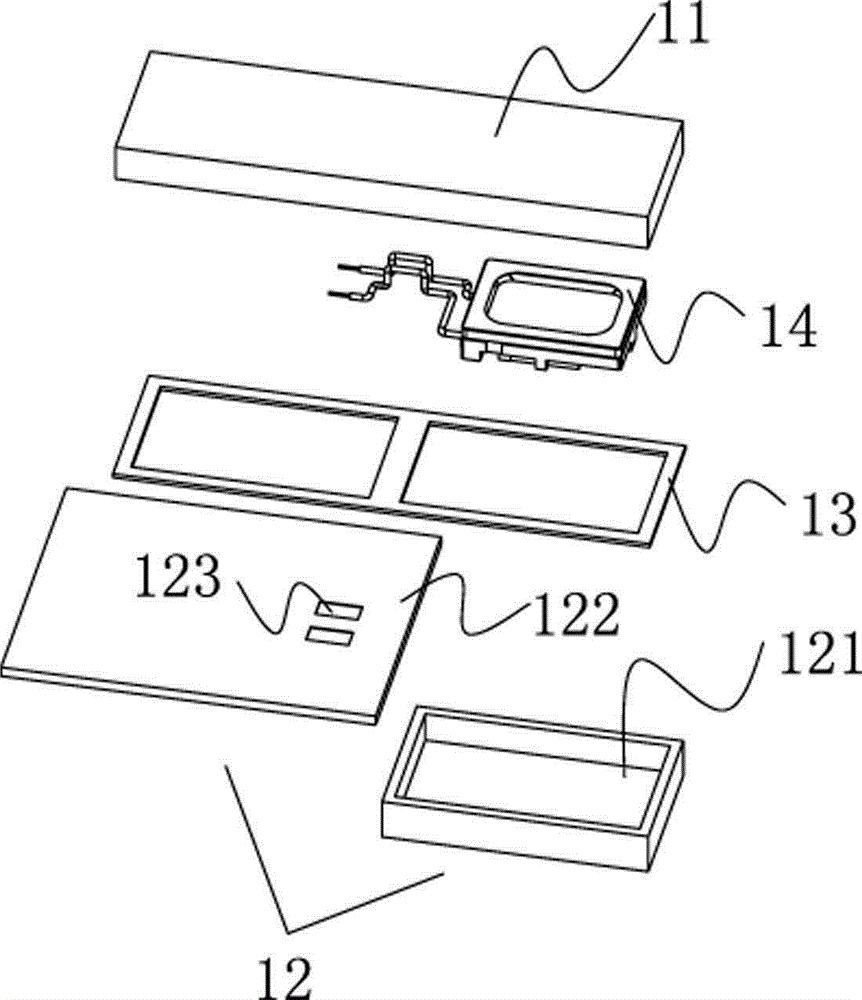
图1是本发明实施例音腔结构的爆炸图。 Fig. 1 is an exploded view of the sound cavity structure of the embodiment of the present invention.
图2是本发明实施例音腔结构的透视图。 Fig. 2 is a perspective view of the sound cavity structure of the embodiment of the present invention.
图3是图2中A-A剖面图。 Fig. 3 is a sectional view of A-A in Fig. 2 .
图4是本发明实施例音腔组装图。 Fig. 4 is an assembly diagram of the sound cavity of the embodiment of the present invention.
图5是图4中B-B剖面图。 Fig. 5 is a B-B sectional view in Fig. 4 .
图6是本发明实施例音腔上盖内部结构图。 Fig. 6 is a diagram of the internal structure of the upper cover of the sound cavity according to the embodiment of the present invention.
具体实施方式 Detailed ways
为了使本发明所解决的技术问题、技术方案及有益效果更加清楚明白,以下结合附图及实施例,对本发明进行进一步详细说明。应当理解,此处所描述的具体实施例仅仅用以解释本发明,并不用于限定本发明。 In order to make the technical problems, technical solutions and beneficial effects solved by the present invention clearer, the present invention will be further described in detail below in conjunction with the accompanying drawings and embodiments. It should be understood that the specific embodiments described here are only used to explain the present invention, not to limit the present invention.
图1是本发明实施例音腔结构的爆炸图,公开了一种音腔结构,包括:音腔上盖11、音腔下盖12和扬声器14;所述音腔上盖11设置有隔断部113,所述音腔上盖11和音腔下盖12构成音腔空间并由隔断部113将所述音腔空间分割形成复数个音腔,所述复数个音腔通过设置在所述隔断部上的通孔连通,所述扬声器设置在复数个音腔的其中之一内。通过相邻两个音腔之间的通孔连通复数个音腔,可以使得原来较小的音腔变大,在电子产品空间有限的情况下使得音腔较大。
Figure 1 is an exploded view of the sound cavity structure of the embodiment of the present invention, which discloses a sound cavity structure, including: a sound cavity
图2是本发明实施例音腔结构的透视图,图3是图2中A-A剖面图,结合图1至图3,本实施例是以两个音腔为例说明,所述音腔结构还包括密封部件13,所述密封部件13设置在音腔上盖11和音腔下盖12之间,所述音腔空间形成密封的空间;本实施例中,音腔下盖12包括下盖本体121和印刷电路板122,所述印刷电路板122和本体121并列设置在密封部件13上,所述扬声器14与所述印刷电路板122电连接,此处印刷电路板122(以下简称PCB板122)。
Fig. 2 is the perspective view of the sound cavity structure of the embodiment of the present invention, Fig. 3 is A-A sectional view in Fig. Including a
在有些实施例中,扬声器14位于由所述音腔上盖11、密封部件13、PCB板122以及隔断部113构成的音腔内,这样的结构,扬声器14的电连接端直接与PCB板122电连接。
In some embodiments, the
在另外一些实施例中,如图2中所示,扬声器14位于由所述音腔上盖11、密封部件13、下盖本体121以及隔断部113构成的音腔内,所述扬声器14的电连接端通过所述通孔112与所述PCB板122电连接。具体地,PCB板122上包括与扬声器14连接的焊盘123,导线141穿过通孔112焊接至焊盘123上并与扬声器14连接,扬声器14通过导线141和焊盘123与音腔外部进行信号传输。本实施例用于容纳扬声器14的音腔20的下盖本体121具有凹槽,刚好用于放置扬声器14,扬声器14的信号可以通过导线141经过通孔112,再经过PCB板122的焊盘123与外部信号连接,这样的结构使得整个音腔的厚度比较薄,进一步满足电子产品对空间小型化的需求。
In some other embodiments, as shown in FIG. 2 , the
图4是本发明实施例音腔组装图,图5是图4中B-B剖面图;由图中可知,扬声器14放置于音腔20中,信号通过导线141连接至音腔30中PCB板上的焊盘123上,通过PCB板122与外部信号连接。导线141穿过两音腔之间的通孔112。密封部件13可以将音腔上盖11和音腔下盖12密封,密封部件13优选为泡棉;泡棉可以采用一个,这样可以有效的减少成本;密封部件13也可以采用黑胶水或者音腔上盖11和音腔下盖12通过超声波焊接进行密封。
Fig. 4 is an assembly diagram of the sound cavity of the embodiment of the present invention, and Fig. 5 is a cross-sectional view of B-B in Fig. 4; as can be seen from the figure, the
图6是本发明实施例音腔上盖内部结构图,音腔上盖11设置有隔断部113,隔断部113上设置有所述通孔112,通孔112可以连通相邻的两个音腔,加大音腔空间。
Fig. 6 is an internal structure diagram of the upper cover of the sound cavity according to the embodiment of the present invention. The upper cover of the
本发明还提供了一种电子产品,包括上述所述的音腔结构。所述音腔结构为上述结构,此处不再赘述。所述电子产品可以是手机、个人数字助理、MP3等具有扬声器音腔结构的电子产品。 The present invention also provides an electronic product, including the sound cavity structure described above. The structure of the sound cavity is the structure described above, which will not be repeated here. The electronic product may be a mobile phone, a personal digital assistant, an MP3, etc., which have a loudspeaker cavity structure.
为了节省空间,可以利用电子产品的外壳作为音腔上盖11或下盖本体121;也可以将电子产品外壳同时作为音腔上盖11和下盖本体121,这样可以有效的节省空间并节约成本。
In order to save space, the shell of the electronic product can be used as the
本发明所提供电子产品,其音腔结构可以在电子产品的有限内部空间中实现音腔空间的最大化,同时保持音腔具有良好的密封效果,且单独的音腔结构还具有很好的兼容性。 The sound chamber structure of the electronic product provided by the present invention can maximize the space of the sound chamber in the limited internal space of the electronic product, while maintaining a good sealing effect of the sound chamber, and the separate sound chamber structure also has good compatibility sex.
以上所述仅为本发明的较佳实施例而已,并不用以限制本发明,凡在本发明的精神和原则之内所作的任何修改、等同替换和改进等,均应包含在本发明的保护范围之内。 The above descriptions are only preferred embodiments of the present invention, and are not intended to limit the present invention. Any modifications, equivalent replacements and improvements made within the spirit and principles of the present invention should be included in the protection of the present invention. within range.
Claims (9)
Priority Applications (1)
| Application Number | Priority Date | Filing Date | Title |
|---|---|---|---|
| CN2011103254932A CN103067798A (en) | 2011-10-24 | 2011-10-24 | Sound cavity structure and electronic product with same |
Applications Claiming Priority (1)
| Application Number | Priority Date | Filing Date | Title |
|---|---|---|---|
| CN2011103254932A CN103067798A (en) | 2011-10-24 | 2011-10-24 | Sound cavity structure and electronic product with same |
Publications (1)
| Publication Number | Publication Date |
|---|---|
| CN103067798A true CN103067798A (en) | 2013-04-24 |
Family
ID=48110230
Family Applications (1)
| Application Number | Title | Priority Date | Filing Date |
|---|---|---|---|
| CN2011103254932A Pending CN103067798A (en) | 2011-10-24 | 2011-10-24 | Sound cavity structure and electronic product with same |
Country Status (1)
| Country | Link |
|---|---|
| CN (1) | CN103067798A (en) |
Cited By (14)
| Publication number | Priority date | Publication date | Assignee | Title |
|---|---|---|---|---|
| CN104038857A (en) * | 2014-06-27 | 2014-09-10 | 深圳市中兴移动通信有限公司 | Sound cavity structure |
| CN105916067A (en) * | 2016-06-29 | 2016-08-31 | 广东欧珀移动通信有限公司 | Sound structure and electronic equipment |
| CN105959835A (en) * | 2016-06-29 | 2016-09-21 | 广东欧珀移动通信有限公司 | Acoustic structure and electronic device |
| CN105959834A (en) * | 2016-06-29 | 2016-09-21 | 广东欧珀移动通信有限公司 | Sound structure and electronic equipment |
| CN106101915A (en) * | 2016-06-29 | 2016-11-09 | 广东欧珀移动通信有限公司 | Sound structure and electronic equipment |
| CN106101916A (en) * | 2016-06-29 | 2016-11-09 | 广东欧珀移动通信有限公司 | Sound structure and electronic equipment |
| CN106341759A (en) * | 2016-08-26 | 2017-01-18 | 深圳市轱辘车联数据技术有限公司 | Sound cavity structure and intelligent walkie-talkie having same |
| CN106993250A (en) * | 2017-05-17 | 2017-07-28 | 广东欧珀移动通信有限公司 | Loudspeaker assembly and mobile terminal |
| CN107071667A (en) * | 2017-05-17 | 2017-08-18 | 广东欧珀移动通信有限公司 | loudspeaker assembly and mobile terminal |
| CN107197398A (en) * | 2017-06-21 | 2017-09-22 | 广东欧珀移动通信有限公司 | Loudspeaker assembly and mobile terminal |
| CN108024181A (en) * | 2016-10-31 | 2018-05-11 | 深圳富泰宏精密工业有限公司 | Electronic device |
| CN109302661A (en) * | 2017-07-25 | 2019-02-01 | 中兴通讯股份有限公司 | a mobile terminal |
| CN111526460A (en) * | 2016-03-28 | 2020-08-11 | 乐金显示有限公司 | Panel vibration type sound-emitting display device |
| US11140482B2 (en) | 2016-03-28 | 2021-10-05 | Lg Display Co., Ltd. | Actuator fixing device and panel vibration type sound-generating display device including the same |
Citations (3)
| Publication number | Priority date | Publication date | Assignee | Title |
|---|---|---|---|---|
| US20070242848A1 (en) * | 2006-04-12 | 2007-10-18 | Foxconn Technology Co., Ltd. | Speaker set and mobile phone incorporating the same |
| CN101198196A (en) * | 2006-12-08 | 2008-06-11 | 富准精密工业(深圳)有限公司 | Loudspeaker box structure and mobile electronic equipments adopting the loudspeaker box structure |
| CN201766626U (en) * | 2010-06-11 | 2011-03-16 | 中兴通讯股份有限公司 | Mobile terminal |
-
2011
- 2011-10-24 CN CN2011103254932A patent/CN103067798A/en active Pending
Patent Citations (3)
| Publication number | Priority date | Publication date | Assignee | Title |
|---|---|---|---|---|
| US20070242848A1 (en) * | 2006-04-12 | 2007-10-18 | Foxconn Technology Co., Ltd. | Speaker set and mobile phone incorporating the same |
| CN101198196A (en) * | 2006-12-08 | 2008-06-11 | 富准精密工业(深圳)有限公司 | Loudspeaker box structure and mobile electronic equipments adopting the loudspeaker box structure |
| CN201766626U (en) * | 2010-06-11 | 2011-03-16 | 中兴通讯股份有限公司 | Mobile terminal |
Cited By (25)
| Publication number | Priority date | Publication date | Assignee | Title |
|---|---|---|---|---|
| CN104038857A (en) * | 2014-06-27 | 2014-09-10 | 深圳市中兴移动通信有限公司 | Sound cavity structure |
| US12395787B2 (en) | 2016-03-28 | 2025-08-19 | Lg Display Co., Ltd. | Sound generating apparatus |
| US11950068B2 (en) | 2016-03-28 | 2024-04-02 | Lg Display Co., Ltd. | Panel vibration type sound generating display device |
| US11736858B2 (en) | 2016-03-28 | 2023-08-22 | Lg Display Co., Ltd. | Panel vibration type sound generating display device |
| US11265655B2 (en) | 2016-03-28 | 2022-03-01 | Lg Display Co., Ltd | Panel vibration type sound generating display device |
| US11140482B2 (en) | 2016-03-28 | 2021-10-05 | Lg Display Co., Ltd. | Actuator fixing device and panel vibration type sound-generating display device including the same |
| US11019425B2 (en) | 2016-03-28 | 2021-05-25 | Lg Display Co., Ltd. | Panel vibration type sound generating display device |
| CN111526460A (en) * | 2016-03-28 | 2020-08-11 | 乐金显示有限公司 | Panel vibration type sound-emitting display device |
| CN105959834B (en) * | 2016-06-29 | 2019-04-19 | Oppo广东移动通信有限公司 | Sound structure and electronic equipment |
| CN105959834A (en) * | 2016-06-29 | 2016-09-21 | 广东欧珀移动通信有限公司 | Sound structure and electronic equipment |
| CN105916067A (en) * | 2016-06-29 | 2016-08-31 | 广东欧珀移动通信有限公司 | Sound structure and electronic equipment |
| CN105959835A (en) * | 2016-06-29 | 2016-09-21 | 广东欧珀移动通信有限公司 | Acoustic structure and electronic device |
| CN106101915A (en) * | 2016-06-29 | 2016-11-09 | 广东欧珀移动通信有限公司 | Sound structure and electronic equipment |
| CN106101916A (en) * | 2016-06-29 | 2016-11-09 | 广东欧珀移动通信有限公司 | Sound structure and electronic equipment |
| CN111294673A (en) * | 2016-06-29 | 2020-06-16 | Oppo广东移动通信有限公司 | Sound structure and electronic equipment |
| CN111294673B (en) * | 2016-06-29 | 2021-09-14 | Oppo广东移动通信有限公司 | Sound structure and electronic equipment |
| CN106341759A (en) * | 2016-08-26 | 2017-01-18 | 深圳市轱辘车联数据技术有限公司 | Sound cavity structure and intelligent walkie-talkie having same |
| CN106341759B (en) * | 2016-08-26 | 2020-02-14 | 深圳市轱辘汽车维修技术有限公司 | Sound cavity structure and intelligent interphone comprising same |
| CN108024181A (en) * | 2016-10-31 | 2018-05-11 | 深圳富泰宏精密工业有限公司 | Electronic device |
| CN106993250A (en) * | 2017-05-17 | 2017-07-28 | 广东欧珀移动通信有限公司 | Loudspeaker assembly and mobile terminal |
| CN107071667A (en) * | 2017-05-17 | 2017-08-18 | 广东欧珀移动通信有限公司 | loudspeaker assembly and mobile terminal |
| CN106993250B (en) * | 2017-05-17 | 2023-01-10 | Oppo广东移动通信有限公司 | Loudspeaker components and mobile terminals |
| CN107197398A (en) * | 2017-06-21 | 2017-09-22 | 广东欧珀移动通信有限公司 | Loudspeaker assembly and mobile terminal |
| CN107197398B (en) * | 2017-06-21 | 2023-09-29 | Oppo广东移动通信有限公司 | Speaker assembly and mobile terminal |
| CN109302661A (en) * | 2017-07-25 | 2019-02-01 | 中兴通讯股份有限公司 | a mobile terminal |
Similar Documents
| Publication | Publication Date | Title |
|---|---|---|
| CN103067798A (en) | Sound cavity structure and electronic product with same | |
| US8867770B2 (en) | Speaker-connector module and handheld electronic device | |
| CN103682853B (en) | Connector modules and handheld electronic devices | |
| CN203181149U (en) | Mobile terminal increasing size of sound cavity of loudspeaker | |
| CN107426365B (en) | Sound cavity structure and mobile phone with same | |
| CN204681568U (en) | A kind of loud speaker module assembly structure | |
| CN104486710A (en) | Loudspeaker and mobile terminal comprising same | |
| CN112291394A (en) | Electronic device | |
| CN202799144U (en) | Micro-electromechanical systems (MEMS) microphone | |
| CN107197398B (en) | Speaker assembly and mobile terminal | |
| CN203883957U (en) | Loudspeaker module | |
| CN109218940B (en) | a terminal | |
| CN107634409B (en) | Sound generating device module and electronic equipment | |
| CN206807767U (en) | Mobile terminal | |
| CN201966990U (en) | Encapsulating structure for loudspeaker | |
| CN206533651U (en) | Water repellent component and mobile terminal | |
| CN101321412B (en) | Miniature microphone | |
| CN201118978Y (en) | electret microphone | |
| CN206923027U (en) | Loudspeaker assembly and mobile terminal | |
| CN102655617B (en) | Microphone and assembly method thereof | |
| CN101442694A (en) | Loudspeaker assembly | |
| CN201160322Y (en) | dustproof microphone | |
| CN204697290U (en) | A MEMS microphone | |
| KR100663490B1 (en) | Speaker device of mobile terminal using antenna mounting space | |
| CN201252640Y (en) | Novel digital microphone |
Legal Events
| Date | Code | Title | Description |
|---|---|---|---|
| C06 | Publication | ||
| PB01 | Publication | ||
| C10 | Entry into substantive examination | ||
| SE01 | Entry into force of request for substantive examination | ||
| C12 | Rejection of a patent application after its publication | ||
| RJ01 | Rejection of invention patent application after publication |
Application publication date: 20130424 |