CN101675577A - Switching Power Converter with Efficient Generation of Switching Control Signal Periods - Google Patents
Switching Power Converter with Efficient Generation of Switching Control Signal Periods Download PDFInfo
- Publication number
- CN101675577A CN101675577A CN200880014453A CN200880014453A CN101675577A CN 101675577 A CN101675577 A CN 101675577A CN 200880014453 A CN200880014453 A CN 200880014453A CN 200880014453 A CN200880014453 A CN 200880014453A CN 101675577 A CN101675577 A CN 101675577A
- Authority
- CN
- China
- Prior art keywords
- cycle
- voltage
- signal
- switch controlling
- controlling signal
- Prior art date
- Legal status (The legal status is an assumption and is not a legal conclusion. Google has not performed a legal analysis and makes no representation as to the accuracy of the status listed.)
- Pending
Links
Images


Classifications
-
- H—ELECTRICITY
- H02—GENERATION; CONVERSION OR DISTRIBUTION OF ELECTRIC POWER
- H02M—APPARATUS FOR CONVERSION BETWEEN AC AND AC, BETWEEN AC AND DC, OR BETWEEN DC AND DC, AND FOR USE WITH MAINS OR SIMILAR POWER SUPPLY SYSTEMS; CONVERSION OF DC OR AC INPUT POWER INTO SURGE OUTPUT POWER; CONTROL OR REGULATION THEREOF
- H02M1/00—Details of apparatus for conversion
- H02M1/42—Circuits or arrangements for compensating for or adjusting power factor in converters or inverters
- H02M1/4208—Arrangements for improving power factor of AC input
- H02M1/4225—Arrangements for improving power factor of AC input using a non-isolated boost converter
-
- H—ELECTRICITY
- H03—ELECTRONIC CIRCUITRY
- H03M—CODING; DECODING; CODE CONVERSION IN GENERAL
- H03M3/00—Conversion of analogue values to or from differential modulation
- H03M3/30—Delta-sigma modulation
- H03M3/458—Analogue/digital converters using delta-sigma modulation as an intermediate step
- H03M3/476—Non-linear conversion systems
-
- Y—GENERAL TAGGING OF NEW TECHNOLOGICAL DEVELOPMENTS; GENERAL TAGGING OF CROSS-SECTIONAL TECHNOLOGIES SPANNING OVER SEVERAL SECTIONS OF THE IPC; TECHNICAL SUBJECTS COVERED BY FORMER USPC CROSS-REFERENCE ART COLLECTIONS [XRACs] AND DIGESTS
- Y02—TECHNOLOGIES OR APPLICATIONS FOR MITIGATION OR ADAPTATION AGAINST CLIMATE CHANGE
- Y02B—CLIMATE CHANGE MITIGATION TECHNOLOGIES RELATED TO BUILDINGS, e.g. HOUSING, HOUSE APPLIANCES OR RELATED END-USER APPLICATIONS
- Y02B70/00—Technologies for an efficient end-user side electric power management and consumption
- Y02B70/10—Technologies improving the efficiency by using switched-mode power supplies [SMPS], i.e. efficient power electronics conversion e.g. power factor correction or reduction of losses in power supplies or efficient standby modes
-
- Y—GENERAL TAGGING OF NEW TECHNOLOGICAL DEVELOPMENTS; GENERAL TAGGING OF CROSS-SECTIONAL TECHNOLOGIES SPANNING OVER SEVERAL SECTIONS OF THE IPC; TECHNICAL SUBJECTS COVERED BY FORMER USPC CROSS-REFERENCE ART COLLECTIONS [XRACs] AND DIGESTS
- Y02—TECHNOLOGIES OR APPLICATIONS FOR MITIGATION OR ADAPTATION AGAINST CLIMATE CHANGE
- Y02P—CLIMATE CHANGE MITIGATION TECHNOLOGIES IN THE PRODUCTION OR PROCESSING OF GOODS
- Y02P80/00—Climate change mitigation technologies for sector-wide applications
- Y02P80/10—Efficient use of energy, e.g. using compressed air or pressurized fluid as energy carrier
Landscapes
- Engineering & Computer Science (AREA)
- Power Engineering (AREA)
- Dc-Dc Converters (AREA)
- Rectifiers (AREA)
- Compression, Expansion, Code Conversion, And Decoders (AREA)
- Control Of Ac Motors In General (AREA)
- Control Of Electrical Variables (AREA)
- Control Of Multiple Motors (AREA)
Abstract
一个功率控制系统包括一开关整流器和控制器,此控制器对通过生成根据如下至少一种而变化的开关控制信号对时变电压电源信号做出反应:(i)开关控制信号的周期与传送至与开关整流器相连的负载的确定功率呈反趋向;(ii)开关控制信号的周期与电压电源信号的瞬时电压水平呈反趋势;和(iii)开关控制信号的周期与时变电压电源信号的线电压水平呈直接趋势。在至少一个实例中,当提供功率功率因素校正(PFC)时,控制器实现具有相关开关损耗的开关周期和传送至开关整流器的瞬时功率之间的高效关联。
A power control system includes a switching rectifier and a controller that responds to a time-varying voltage supply signal by generating a switching control signal that varies according to at least one of the following: (i) the period of the switching control signal is inversely related to a given power delivered to a load connected to the switching rectifier; (ii) the period of the switching control signal is inversely related to the instantaneous voltage level of the voltage supply signal; and (iii) the period of the switching control signal is directly related to the line voltage level of the time-varying voltage supply signal. In at least one instance, when power factor correction (PFC) is provided, the controller achieves an efficient correlation between the switching period with associated switching losses and the instantaneous power delivered to the switching rectifier.
Description
优先权要求和相关专利申请Priority claims and related patent applications
本专利申请要求依据35U.S.C.§119(e)和37C.F.R.§1.78享有2007年5月2日递交名为“功率因数校正(PFC)控制器装置和方法”(Power Factor Correction(PFC)Controller Apparatuses andMethods)的60/915,547号美国临时专利申请的权益,其通过引用被整体纳入本专利申请。This patent application claims the benefit under 35 U.S.C.§119(e) and 37C.F.R.§1.78 filed on May 2, 2007 entitled "Power Factor Correction (PFC) Controller Apparatus and Method" (Power Factor Correction (PFC) Controller Apparatuses and Methods, U.S. Provisional Patent Application No. 60/915,547, which is hereby incorporated by reference in its entirety.
技术领域 technical field
本发明大体涉及到电子学领域及,尤其是通过高效生成开关控制信号周期的开关功率变换器转换电压的系统和方法。The present invention relates generally to the field of electronics and, more particularly, to systems and methods for converting voltages by switching power converters that efficiently generate periods of switching control signals.
背景技术 Background technique
很多装置利用功率操作。功率最初由一电源提供,如一个公用事业公司,通常它提供稳定输入电压。然而,各种设备使用的电压等级有别于电源所提供的稳定输入电压。例如,基于发光二极管(LED)的照明系统,工作于非公用事业公司所提供的电压等级下。为了调节来自电源电压与装置需要利用电压的区别,功率变换器连接于电源和装置之间,以将交流电(AC)源提供的电压水平转换为,如,另外一不同于所供电压水平的AC交流电源。整功率变换器还可以将AC功率转换为DC(直流电)功率和将DC功率转换为AC功率。Many devices operate on power. Power is initially provided by a source, such as a utility company, which typically provides a regulated input voltage. However, the voltage level used by various devices is different from the stable input voltage provided by the power supply. For example, lighting systems based on light-emitting diodes (LEDs) operate at voltage levels other than those provided by the utility company. In order to adjust the difference between the voltage from the power supply and the voltage required by the device, a power converter is connected between the power source and the device to convert the voltage level provided by the alternating current (AC) source to, for example, another AC voltage level different from the supplied voltage level. AC power. A full power converter can also convert AC power to DC (direct current) power and DC power to AC power.
开关开关功率变换器即为一类功率变换器的实例。开关功率变换器利用开关及能源储存技术将输入电压转换为一部分与其相连的设备适宜的输出电压。A switching power converter is an example of a class of power converters. Switching power converters use switching and energy storage technology to convert an input voltage to an output voltage suitable for a portion of the equipment connected to it.
图1描绘的是功率控制系统100,它包括:开关功率变换器102,电压电源101提供AC输入“mains”电源主电压Vmains至二极管全桥式整流器103。所述电压电源101为,例如,一公用事业单位,而AC电源电压Vmains则为,例如,在美国为60Hz/120V,在欧洲为50Hz/230V。整流器103对输入的电源电压Vmains进行整流。整流器103将输入的电源电压Vmains进行整流,并向开关功率转换器提供一个经过整流的,随时间而变的初级供电电压VX。开关功率变换器102提供近乎恒定的电压功率至负载112的同时对电压电源101维持阻抗输入特性。对电压电源101维持阻性输入特性时提供近乎恒定的电压电力至负载112,这就被称为功率因素校正(PFC)。因此,控制功率因素校正后的开关整流器102可使输入至开关整流器102的电流iL产生与AC电源电压Vmains近乎成比例的变化。FIG. 1 depicts a power control system 100 comprising a switching power converter 102 , a voltage source 101 providing an AC input “mains” supply mains voltage V mains to a diode
PFC和输出电压控制器114控制PFC开关108的导电性,从而提供功率因数校正并调节开关功率变换器102的输出电压VC。PFC和输出电压控制器114通过控制电感电流iL以使平均电感电流iL成线性并直接与初级供电电压VX成比例。电感电流iL与初级供电电压VX的比例系数被调整以调节至负载112的电压。PFC和输出电压控制器114提供一个脉冲宽度调制的(PWM)控制信号CS0,以控制开关108的导通性。在至少一个实施例中,开关108是一个场效应晶体管(FET),而控制信号CS0是开关108的栅极电压。控制信号CS0的脉冲宽度值和占空比取决于两个反馈信号,即初级供电电压VX和电容电压/输出电压VC。一般也将输出电压VC称为“链接电压”。电流控制回路119提供电流iRTN至PFC和输出电压控制器114,以使PFC和输出电压控制器114调节平均iL电流210(图2),使其等于目标iL电流208(图2)。The PFC and output voltage controller 114 controls the conductivity of the
当二极管111为反向偏置和初级供电电压VX低于输入电源的RMS值时,电容器106提供储能至负载112。电容器106的值与设计选择相关。在至少一个实例中,它非常大以维持非常稳定输出电压VC,由PFC和输出电压控制器114确定。当使用400V输出电压VC时,电容器106的值为1微法每瓦由开关整流器102提供的最大输出功率。在稳定负载条件随初级供电电压VX频率波动期间,输出电压VC保持在几乎恒定的目标值。然而,输出电压VC随负载条件变化而变化。PFC和输出电压控制器114随输出电压VC变化而变化,通过调节开关控制信号CS0还原输出电压VC至目标值以响应电压CS0的变化。在至少一个实例中,PFC和输出电压控制器114包括一小电容115,以从初级供电电压VX过滤任何高频信号。Capacitor 106 provides energy storage to load 112 when diode 111 is reverse biased and primary supply voltage V X is lower than the RMS value of the input supply. The value of capacitor 106 is a matter of design choice. In at least one instance, it is very large to maintain a very stable output voltage V C , as determined by the PFC and output voltage controller 114 . Capacitor 106 has a value of 1 microfarad per watt for the maximum output power provided by switching rectifier 102 when using an output voltage V C of 400V. During steady load conditions with primary supply voltage V X frequency fluctuations, the output voltage V C remains at a nearly constant target value. However, the output voltage V C varies with load conditions. The PFC and the output voltage controller 114 change with the change of the output voltage V C , and restore the output voltage V C to the target value by adjusting the switch control signal CS 0 in response to the change of the voltage CS 0 . In at least one example, the PFC and output voltage controller 114 includes a
因为寄生阻抗,每次开关108切换于绝缘和传导状态时开关功率变换器102产生开关损耗。寄生阻抗包括经过开关108的寄生电容132。在切换开关控制信号CS0每周期TT,能源被用于,例如,充电寄生电容132。因此,开关功率变换器102在开关控制信号CS0的各周期TT产生开关损耗。Because of parasitic impedances, switching power converter 102 generates switching losses each time switch 108 switches between the insulating and conducting states. The parasitic impedance includes
PFC和输出电压控制器114控制开关功率变换器102,从而传送需求量的功率至电容器106。电力的需要量取决于负载112需求的电压和电流。输入电压控制回路116提供初级供电电压VX的样本至PFC和输出电压控制器114。PFC和输出电压控制器114确定参考电压VREF(表示输出电压VC的目标电压)和实际输出电压VC(感应自节点122并作为接收自电压回路118的反馈信号)的差别。PFC和输出电压控制器114普遍利用如下技术,如PI补偿控制,以对参考电压VREF相关的输出电压VC中的差别作出反应。PFC和输出电压控制器114处理此差别,以顺利地调节输出电压进而避免因对小错误信号产生响应而产生输出电压VC快速波动。PFC和输出电压控制器114生成脉宽调制的开关控制信号CS0进而驱动开关108。参见

图2和3分别描绘开关控制策略。其为典型的开关功率变换器,如开关功率变换器102,用以转换输入电压VX为功率因数矫正后的输出电压VC。图2描述过渡开关策略,图3描述稳定周期开关策略。参考图1和2,PFC和输出电压控制器114控制PFC开关108的传导率。在至少一个实例中,初级供电电压VX 202为整流正弦波。为了调节传输的能量并将功率因数保持在接近1,PFC和输出电压控制器114改变着控制信号CS0的周期,使输入电流iL能够追踪到输为了调节传输能源量并维持功率因数接近1,PFC和输出电压控制器114改变开关控制信号CS0的期间TT,以使电感电流iL(作为“输入电流”引用)跟踪初级供电电压VX的变化并保持输出电压VC稳定。过转换开关策略204阐述的是,当初级供电电压VX增加时,PFC和输出电压控制器114增加开关控制信号CS0的周期TT。当初级供电电压VX降低时,PFC和输出电压控制器114降低开关控制信号CS0的周期。在转换开关策略204的一个实例中,脉宽时间T1近乎恒定。Figures 2 and 3 depict switch control strategies, respectively. It is a typical switching power converter, such as the switching power converter 102 , used to convert the input voltage V X into the output voltage V C after power factor correction. Figure 2 describes the transition switching strategy and Figure 3 describes the steady cycle switching strategy. Referring to FIGS. 1 and 2 , the PFC and output voltage controller 114 controls the conductance of the
时间T2代表感应器110的回扫时间,这种情况发生于开关108绝缘及二极管111导电条件下。在至少一个实例中,感应器110的值与设计选择有关。在至少一个实例中,所选感应器110的值可储备足够的能量(当开关108导电时传输自电压电源101的能量),从而在当开关108绝缘时传输能量至电容器106并进而维持需要的输出电压VC。对于转换开关策略204,脉宽时间T1加上回扫时间T2等于开关控制信号CS0的周期TT。Time T2 represents the retrace time of the
电感电流iL波形206描述电感电流iL随时间变化与初级供电电压VX。当开关108导电,即处于“ON”的状态时,电感电流iL在脉宽T1中增加。当开关108绝缘,如处于“OFF”状态时,电感器电流在回扫时间T2中下降,并通过二极管111提供电感电流iL以对电容器106再充电。当开关控制信号CS0处于周期TT电感电流iL达到0时,发生不连续导电模式(DCM)。当在整个周期TT电感电流iL超过0时,发生连续导电模式(CCM)。当电感电流iL等于0时,转换开关策略204通过开始开关控制信号CS0的各周期,在DCM和CCM的边界,操作开关功率变换器102。例如,开关信号CS0的频率1/TT在20kHz至130kHz之间。开关控制信号CS0的周期TT和诱导电流iL波形206中描绘的诱导电流iL每循环持续时间被延长,便于视觉观察。当小功率转换自电压电源101时,过渡开关策略204在高频率操作开关108,如接近电源电压Vmains的过零点212,并在轻负荷,如当负载112的功率需求轻时。The inductor current i L
PFC和输出电压控制器114设置一追踪初级供电电压VX的目标电流208。当电感电流iL在脉宽T1达到目标电流208时,开关控制信号CS0打开开关108,然后电感电流iL在回扫时间T2降至0。平均电流210代表平均电感电流iL。平均电感电流iL追踪初级供电电压VX从而提供功率因素校正。The PFC and output voltage controller 114 sets a target current 208 that tracks the primary supply voltage V X . When the inductor current i L reaches the target current 208 during the pulse width T1, the switch control signal CS 0 turns on the
根据图3,周期恒定开关策略302保持开关控制信号CS0的稳定周期TT,并改变开关控制信号CS0的脉宽T1以控制电感电流iL。当初级供电电压VX从0增加至峰值时,PFC和输出电压控制器114降低开关控制信号CS0的脉宽T1稳定周期开关策略302操作DCM中的开关整流器102从而使回扫时间T2加脉宽T1小于或等于开关控制信号CS0的周期TT。电感电流iL波形304描述的是稳定周期开关策略302在诱导电流iL的效果与初级供电电压VX相关。使至于为周期恒定开关策略302而设计的转换开关策略204,PFC和输出电压控制器114设定目标电流208以追踪初级供电电压VX。对稳定周期策略302,TT≥(T1+T2),所述整流器102运行于DCM。According to FIG. 3 , the cycle
PFC和输出电压控制器114以比输入电压VX频率更高的频率更新开关控制信号CS0。输入电压VX的频率一般为50-60Hz。开关控制信号CS0的频率1/TT为,如,在10kHz和130kHz之间。等于或高于20kHz的频率避开了可闻及频率,并且等于或低于130kHz的频率避免显著的开关无效率。The PFC and output voltage controller 114 updates the switch control signal CS 0 at a higher frequency than the input voltage V X frequency. The frequency of the input voltage V X is generally 50-60 Hz. The
从开关损耗对传输至负载112的能量的方面来说,稳定周期开关策略302为无效率。与其相比,过渡开关策略204则更为低效率。The steady
发明内容 Contents of the invention
在本发明的一个实例中,一个系统包括一个生成开关控制信号,以控制开关功率变换器中开关的传导率。控制开关的电阻率使输入至开关整流器的电流发生与输入至开关整流器的电压电源信号成比例的变化。控制开关的导电性使输入至开关功率变换器的电流发生与输入至开关功率变换器的电压电源信号成比例的变化:In one embodiment of the invention, a system includes a system for generating a switch control signal to control the conductance of a switch in a switching power converter. Controlling the resistivity of the switch causes the current input to the switching rectifier to vary in proportion to the voltage supply signal input to the switching rectifier. Controlling the conductivity of the switch causes the current input to the switching power converter to vary proportionally to the voltage supply signal input to the switching power converter:
(i)开关控制信号的周期与传输至开关功率变换器相连负载的估算功率呈负相关;(i) The period of the switch control signal is inversely related to the estimated power delivered to the load connected to the switching power converter;
(ii)开关控制信号的周期与时变电压电源信号的瞬时电压水平呈负相关;和(ii) the period of the switch control signal is inversely related to the instantaneous voltage level of the time-varying voltage supply signal; and
(iii)开关控制信号的周期与时变电压电源信号的线电压水平呈正相关;和(iii) the period of the switch control signal is positively correlated with the line voltage level of the time-varying voltage supply signal; and
控制器也包括一脉宽发生器与以下至少一个响应以确定开关控制信号的脉宽:(i)开关控制信号的确定周期,(ii)电压电源信号的瞬时电压水平,和(iii)开关功率变换器输出电压信号的电压水平。The controller also includes a pulse width generator responsive to at least one of the following to determine the pulse width of the switch control signal: (i) the determined period of the switch control signal, (ii) the instantaneous voltage level of the voltage supply signal, and (iii) the switch power The voltage level of the converter output voltage signal.
在本发明的另外一个实例中,一种方法包括生成开关控制信号,以控制开关功率变换器中开关的导电性。控制开关的导电性使输入至开关功率变换器的电流发生与输入至开关功率变换器的电压电源信号成比例的变化。此方法另外包括确定开关控制信号的周期,从而使开关控制信号的周期发生与以下因素中至少一个对应的变化:In another example of the present invention, a method includes generating a switch control signal to control conductivity of a switch in a switching power converter. Controlling the conductivity of the switch causes the current input to the switching power converter to vary in proportion to the voltage supply signal input to the switching power converter. The method additionally includes determining a period of the switch control signal such that the period of the switch control signal varies corresponding to at least one of the following factors:
(i)开关控制信号的周期与传输至开关功率变换器相连负载的估算功率呈负相关;(i) The period of the switch control signal is inversely related to the estimated power delivered to the load connected to the switching power converter;
(ii)开关控制信号的周期与电压电源信号的瞬时电压水平呈负相关;和(ii) the period of the switch control signal is inversely related to the instantaneous voltage level of the voltage supply signal; and
(iii)开关控制信号的周期与时变电压电源信号的线电压水平呈正相关;(iii) The period of the switch control signal is positively correlated with the line voltage level of the time-varying voltage power supply signal;
此方法也包括与以下至少一个响应以确定开关控制信号的脉宽:(i)开关控制信号的确定周期,(ii)电压电源信号的电压水平,和(iii)开关功率变换器输出电压信号的电压水平。此方法另外包括提供开关控制信号至开关功率变换器。The method also includes determining a pulse width of the switch control signal in response to at least one of: (i) a determined period of the switch control signal, (ii) a voltage level of the voltage supply signal, and (iii) a period of the switching power converter output voltage signal voltage level. The method additionally includes providing a switch control signal to the switching power converter.
在本发明的另外一个实例中,一套装置包括用来生成开关控制信号并控制开关功率变换器中开关模式开关导电性的多种组件。控制开关的导电性使输入至开关功率变换器的电流发生与输入至开关功率变换器的电压电源信号成比例的变化。此装置另外包括用来确定开关控制信号的周期,从而使开关控制信号的周期发生与以下因素中至少一个对应的变化的组件:In another embodiment of the present invention, an apparatus includes various components for generating a switch control signal and controlling the conductivity of a switch mode switch in a switching power converter. Controlling the conductivity of the switch causes the current input to the switching power converter to vary in proportion to the voltage supply signal input to the switching power converter. The apparatus additionally includes means for determining a period of the switch control signal such that the period of the switch control signal varies corresponding to at least one of the following factors:
(i)开关控制信号的周期与传输至开关功率变换器瞬时功率呈负相关;(i) The period of the switch control signal is negatively correlated with the instantaneous power transmitted to the switching power converter;
(ii)开关控制信号的周期与电压电源信号的电压水平改变呈负相关;和(ii) the period of the switch control signal is inversely related to the voltage level change of the voltage supply signal; and
(iii)开关控制信号的周期与时变电压电源信号的线电压水平呈正相关;和(iii) the period of the switch control signal is positively correlated with the line voltage level of the time-varying voltage supply signal; and
此装置也包括用来与以下至少一个响应以确定开关控制信号的脉宽的组件:(i)开关控制信号的确定周期,(ii)电压电源信号的电压水平,和(iii)开关功率变换器输出电压信号的电压水平。The apparatus also includes means for determining the pulse width of the switch control signal in response to at least one of: (i) the determined period of the switch control signal, (ii) the voltage level of the voltage supply signal, and (iii) the switching power converter The voltage level of the output voltage signal.
附图说明 Description of drawings
通过参考附图,本领域内的技术人员可更容易理解本发明,并搞清楚它的多种客体,特征和优势。贯穿多幅图的相同参考数字指的是相同或相似的元件。By referring to the accompanying drawings, those skilled in the art can more easily understand the present invention, and realize its various objects, features and advantages. The same reference numbers are used throughout the several figures to refer to the same or similar elements.
图1(标记为已有技术)描绘的是一包括开关功率变换器的功率控制系统。Figure 1 (labeled prior art) depicts a power control system including a switching power converter.
图2(标记的已有技术)描述转换开关控制策略及其在图1所示的开关功率变换器的电感电流中的效果。FIG. 2 (labeled prior art) depicts the transfer switch control strategy and its effect on the inductor current of the switching power converter shown in FIG. 1 .
图3(标记的已有技术)描绘周期恒定开关策略及其在图1所示的开关功率变换器的电感电流中的效果。电感电流中的效果。FIG. 3 (labeled prior art) depicts the cycle constant switching strategy and its effect on the inductor current of the switching power converter shown in FIG. 1 . effect on the inductor current.
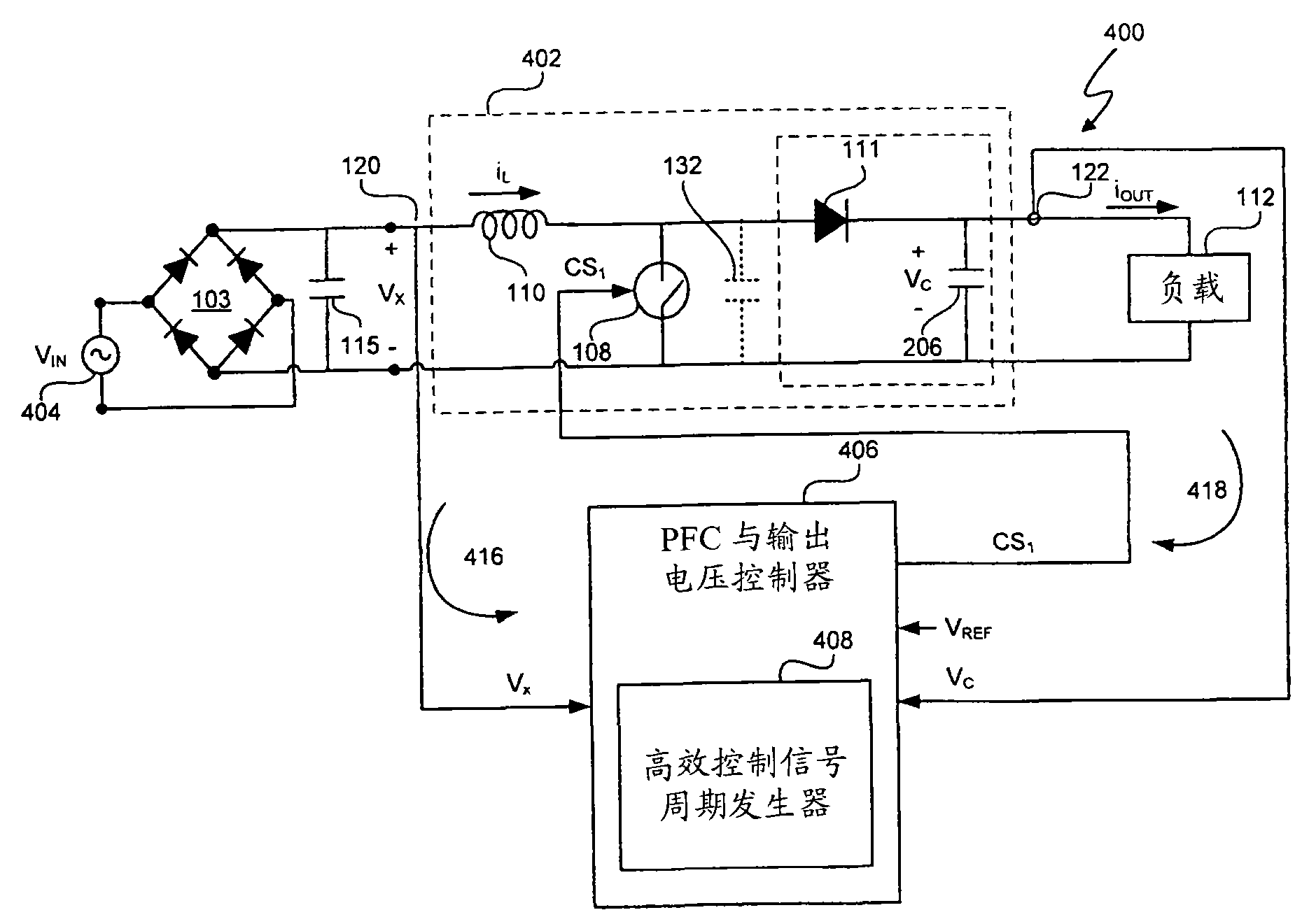
图4描绘的是一功率控制系统,其特征为具有一开关功率变换器和一控制信号周期-功率传送相关性策略模块。FIG. 4 depicts a power control system featuring a switching power converter and a control signal period-power transfer correlation strategy module.
图5描绘的是相关波形集合,其系描述初级供电电压,电感电流和传送至图4所示的功率控制系统的功率之间的关系。Figure 5 depicts a set of related waveforms describing the relationship between the primary supply voltage, the inductor current and the power delivered to the power control system shown in Figure 4 .
图6描述的是高效的周期-瞬时初级供电电压VX相关策略。Figure 6 depicts an efficient cycle-instantaneous primary supply voltage V X correlation strategy.
图7描绘的是相关波形,其系与与电感应电流和图4所示的功率控制系统的开关控制信号相关。FIG. 7 depicts the relevant waveforms associated with the inductor current and switching control signals of the power control system shown in FIG. 4 .
图8描绘的是功率因数校正(PFC)和图4所示的功率控制系统的输出电压控制器。FIG. 8 depicts the power factor correction (PFC) and output voltage controller of the power control system shown in FIG. 4 .
图9-13描绘的是高效的周期-瞬时初级供电电压VX相关策略。Figures 9-13 depict highly efficient cycle-instantaneous primary supply voltage V X correlation strategies.
图14描绘的是非线性Δ-∑调制器。Figure 14 depicts a nonlinear delta-sigma modulator.
图15描绘的是一比例积分器。Figure 15 depicts a proportional integrator.
图16和17描绘的是均方根值发生器。Figures 16 and 17 depict the rms generator.
图18描绘的是PFC和图4所示的功率控制系统的输出电压控制器的另一个实例。FIG. 18 depicts another example of the PFC and output voltage controller of the power control system shown in FIG. 4 .
图19-21描绘的是高效的周期-功率转换-瞬时初级供电电压相关策略,以增加初级供电RMS电压和功率转换百分比。Figures 19-21 depict highly efficient cycle-power conversion-instantaneous primary supply voltage related strategies to increase primary supply RMS voltage and power conversion percentage.
具体实施方式 Detailed ways
一个功率控制系统包括一开关功率变换器和控制器,通过生成对如下至少一种产生相应变化的开关控制信号,此控制器对时变电压电源信号做出反应:i)开关控制信号的周期与传送至与开关功率变换器相连的负载的确定功率呈负相关;(ii)开关控制信号的周期与电压电源信号的瞬时电压水平呈负相关;和(iii)开关控制信号的周期与时变电压电源信号的线电压水平呈正相关。功率控制系统也包括一脉宽发生器,用于确定开关控制信号的脉宽,作为对如下因素的反应:(i)开关控制信号的确定周期,(ii)电压电源信号的瞬时电压,及(iii)开关功率变换器输出电压信号的电压水平。因此,周期可以根据变量的单相函数,双相函数或三相函数确定。(i)传送至与开关功率变换器相连的负载的确定功率;(ii)电压电源信号的瞬时电压水平;和(iii)时变电压电源信号的线电压水平(总体被称作“周期确定变量”)。“单相函数”指的是周期确定变量(i),(ii),或(iii)中任意一种被用来确定开关控制信号周期。“双相函数”指的是周期确定变量(i),(ii),或(iii)中的任意两种被用来确定开关控制信号周期。“三相函数”指的是周期确定变量(i),(ii),或(iii)中的任意三种被用来确定开关控制信号周期。A power control system includes a switching power converter and a controller that responds to a time-varying voltage supply signal by generating a switching control signal that varies correspondingly to at least one of: i) the period of the switching control signal and The determined power delivered to the load connected to the switching power converter is inversely related; (ii) the period of the switch control signal is inversely related to the instantaneous voltage level of the voltage supply signal; and (iii) the period of the switch control signal is inversely related to the time-varying voltage The line voltage level of the power signal is positively correlated. The power control system also includes a pulse width generator for determining the pulse width of the switch control signal in response to (i) the determined period of the switch control signal, (ii) the instantaneous voltage of the voltage supply signal, and ( iii) The voltage level of the output voltage signal of the switching power converter. Thus, the period can be determined from a single-phase function, a two-phase function or a three-phase function of the variables. (i) the deterministic power delivered to the load connected to the switching power converter; (ii) the instantaneous voltage level of the voltage supply signal; and (iii) the line voltage level of the time-varying voltage supply signal (collectively referred to as the "periodic deterministic variable" "). "Single-phase function" means that any one of the period determining variables (i), (ii), or (iii) is used to determine the period of the switch control signal. "Biphase function" means that any two of the period determining variables (i), (ii), or (iii) are used to determine the period of the switch control signal. "Three-phase function" means that any three of the period determining variables (i), (ii), or (iii) are used to determine the period of the switch control signal.
对具有近似正弦波电压电源信号的电力供应,当电压电源信号的相位角在45°和135°之间时开关整流器从电压电源传输80%的功率至负载。开关功率变换器中的开关损耗随着开关周期降低而减少,或换言之,开关功率变换器中的开关损耗随着开关频率的升高而增加。通过改变开关控制信号的周期,周期可根据周期确定变量的单相函数,双相函数或三相函数产生相应变化,在至少一个实例中,当提供功率因数校正(PFC)时,控制器在具有相关开关损耗的开关周期和周期确定变量之间实现高效相关性。For power supplies with approximately sinusoidal voltage supply signals, the switching rectifier delivers 80% of the power from the voltage supply to the load when the phase angle of the voltage supply signal is between 45° and 135°. Switching losses in switching power converters decrease as the switching period decreases, or in other words, switching losses in switching power converters increase as switching frequency increases. By changing the period of the switch control signal, the period can be varied according to a single-phase function, a two-phase function or a three-phase function of the period determination variable. In at least one example, when providing power factor correction (PFC), the controller has An efficient correlation is achieved between the switching period and period-determining variables of the associated switching losses.
图4描绘的是具有开关功率变换器402和高效控制信号周期发生器408的功率控制系统400。在至少一个实例中,开关功率变换器402的设置方法如开关功率变换器102一样。整流器103整流由电压电源404提供的输入电压VIN以生成时变的初级供电电压VX。在至少一个实例中,电压电源404与电压电源101相同,输入电压VIN与电源电压Vmains相同。功率控制系统400也包括PFC和输出电压控制器406。PFC和输出电压控制器406使用代表初级供电电压VX和输出电压VC的反馈信号生成开关控制信号CS1。PFC和输出电压控制器406包括高效控制信号周期发生器408,以有效地关联开关控制信号CS1的周期TT和周期确定变量从而,例如,增加功率控制系统400的效率。FIG. 4 depicts a
在至少一个实例中,此周期确定变量为:i)传送至负载112的确定功率,(ii)初级供电电压VX的瞬时电压水平,和(iii)初级供电电压VX的线电压水平。在至少一个实例中,传输至负载112的估计功率通过将平均输出电压VC(通过电压控制回路418获得)和开关整流器402的平均输出电流iOUT相乘估算出。在至少一个实例中,传送至负载112的估计功率用“K”表示,并通过图8所示的负载功率需求估算器803确定。在至少一个实例中,初级供电电压VX的瞬时电压水平代表初级供电电压VX的一个值,此值通过比率约等于1/TT(1/TT代表开关控制信号CS1的频率)的电压回路416抽样得出。所谓“瞬时”包括延时,如在初级供电电压VX的抽样值获取中的任何传输和处理延时。在至少一个实例中,初级供电电压VX的线电压水平代表至少一个周期的初级供电电压VX。例如,在至少一个实例中,线电压水平是初级供电电压VX的均方根(RMS),初级供电RMS电压的峰值VX_RMS,或初级供电电压VX,的平均值。例如,在美国线电压标称为120Vrms,而在欧洲则标称为230Vrms,其中,“Vrms”代表1个RMS伏特。一般来说,线电压水平和负载功率需求将在50-240Hz的频率更新,瞬时电压将会以开关108的开关频率更新,如开关控制信号CS1的频率。In at least one example, the period determining variables are: i) the determined power delivered to the
在至少一个实例中,所述高效控制信号周期发生器408包括一控制信号周期策略,以使PFC和输出电压控制器406生成开关控制信号CS1的周期TT(根据至少一种周期确定变量变化)。In at least one example, the high-efficiency control
图5描述的是相关波形500的合集,其系描述初级供电电压VX502,电感电流iL504和从电压电源404传送至开关整流器402的功率506之间的相关性。初级供电电压VX周期的一半发生于相位角0°-45°和135°-180°。初级供电电压VX的RMS电压等于在相位角45°和135°的电压。如此,在等于初级供电电压VX的半个周期TT的时间,初级供电电压VX大于初级供电RMS电压VX_RMS,而在等于半个周期TT的时间,小于初级供电RMS电压VX_RMS。正弦波初级供电电压VX的峰值电压为√2·VX_RMS。为提供功率因素校正,PFC和输出电压控制器406生成开关控制信号CS1,以使平均电感电流iL 508追踪初级供电电压VX。从电压电源404传送至开关整流器402的功率506等于VX·iL。当初级供电电压VX大于初级供电RMS电压VX_RMS时,功率506的百分之八十被传送至开关整流器402,当当初级供电电压VX小于初级供电RMS电压VX_RMS时,功率506的百分之二十被传送。换言之,当初级供电电压VX在相位角45°和135°之间时,功率506的80%被传送,当处于初级供电电压VX波谷时,功率506的20%被传送。在至少一个实例中,初级供电电压VX的波谷低于初级供电RMS电压VX_RMS,对正弦波,其相位角在0°-45°和135°-180°。FIG. 5 depicts a collection of correlated
因为寄生阻抗,每次开关108切换于绝缘和传导状态时开关整流器402产生开关损耗。在开关控制信号CS1的每个周期TT,功率被用于,例如,充电寄生电容132。在开关控制信号CS1的每周期TT,开关整流器402产生开关损耗。因此,控制信号CS1的频率越高,开关损耗越高。Because of the parasitic impedance, the switching
根据图1-5,关于传统过渡开关策略204,开关控制信号CS0的频率在相位角0°-45°和135°-180°为最高。因此,在最低量的功率从电压电源101传送至开关整流器102的时间内统过渡开关策略204引起最大的开关损耗。在至少一个实例中,与传统过渡开关策略204相关的开关损耗中超过一半(>50%)发生于20%功率从电压电源101至开关整流器102的传送过程中。稳定周期开关策略302则更为高效因为与传统过渡开关策略204相关的开关损耗中只有大约一半(50%)发生于20%功率从电压电源101至开关整流器102的传送过程中。According to FIGS. 1-5 , regarding the conventional
在至少一个实例中,高效控制信号周期发生器408使PFC和输出电压控制器406通过增加开关控制信号CS1的周期TT以改善功率控制系统400的功率。或换言之,在低功率传送至负载112,低瞬时初级供电电VX和(或)高初级供电RMS电压VX_RMS时降低开关108的开关率。表1阐述典型开关损耗和功率转换率对比。实际节电和优化的开关控制信号CS1周期TT发生策略取决于功率控制系统400的功率器件。In at least one example, the high efficiency control
表1Table 1
如前文所述,在至少一个实例中,初级供电电压VX的波谷低于初级供电RMS电压VX_RMS,对正弦波,其相位角在0°-45°和135°-180°。As previously mentioned, in at least one example, the troughs of the primary supply voltage V X are lower than the primary supply RMS voltage V X — RMS , with phase angles between 0°-45° and 135°-180° for sine waves.
图6描述的是对高效控制信号周期发生器408,典型的高效周期-瞬时初级供电电压VX关联策略600。根据图5和6,随着初级供电电VX向峰值电压√2·VX_RMS增加时,从电压电源404传送至开关整流器402的功率非线性增加。对任何初级供电电压VX和开关功率变换器402输出功率的给定值,存在优化开关周期TT。此优化周期通常在初级供电电压VX的波谷时增加。若周期TT太短,则会存在过度的开关损失。若周期TT太长,寄生阻抗中将会存在过量损耗,如开关108和感应器110各自的阻抗及感应器110的芯损耗。高效周期-瞬时初级供电电压VX关联策略600提供策略以确定周期TT为瞬时初级供电电压VX的函数。周期TT的优化值的实际值与设计选择相关,并且,如,取决于开关整流器402的各部件的值,如感应器110,开关108,电容器106,二极管111的特性,以及瞬时初级供电电压VX,初级供电RMS电压VX_RMS和传送至负载112的功率。在至少一个实例中,功率控制系统400比常规功率控制系统100更有效率,因为开关108的开关频率随着电压电源404提供的功率的增加而增加,从而,控制器实现开关周期与开关108的相关开关损耗之间的高度关联。FIG. 6 depicts a typical high-efficiency period-instantaneous primary supply voltage V X correlation strategy 600 for the high-efficiency control
在至少一个实例中,开关整流器402运行于DCM中。譬如说,控制信号CS1的频率1/TT介于10kHz and 130kHz之间。开关控制信号CS1的周期TT和诱导电流iL波形504中描绘的诱导电流iL各循环持续延长,以便于提高视觉清晰度。In at least one example, switching
图7描绘的是典型电感电流iL和开关控制信号CS1之间典型关联波形700。在开关控制信号CS1的各脉宽的周期T1中,电感电流iL随着从电压电源404传送至感应器110而升高。在回扫时间T2,电感电流iL随着感应器储能量充电电容器106降低。平均电感电流iL_AVG 706追踪初级供电电压VX从而提供功率因素校正。FIG. 7 depicts a
图8描述的是PFC和输出电压控制器800,其系代表PFC和输出电压控制器406的一个实例。PFC和输出电压控制器800依据由控制信号周期发生器策略模块802实施的开关控制信号发生策略确定开关控制信号CS1。高效控制信号周期发生策略模块802代表高效控制信号周期发生器408的一个实例。在至少一个实例中,控制信号周期发生策略模块802生成TT,作为以下中至少一个的函数:瞬时初级供电电压VX和传送至负载112的估计功率。在至少一个实例中,此控制信号周期策略模块802生成TT为初级供电电压VX和传送至负载112的估计功率两者的函数。FIG. 8 depicts a PFC and
PFC和输出电压控制器800确定周期TT和开关控制信号CS1的脉宽T1,以,例如,对开关整流器402提供功率传送效率和功率因素校正。在至少一个实例中,传送至负载112的估计功率由“K”代表,为功率控制回路418中的负载功率需求估算器803的输出值。在至少一个实例中,脉宽周期T1的平方,如T12,根据等式1确定。PFC and
“T1”为控制信号CS1的脉宽(接通持续时间)。“L”表示电感器110的电感值。VX_RMS代表初级供电RMS电压VX_RMS。“K”代表负载112的功率需求的估计值,它由负载功率需求估计器803确定。“TT”是控制信号CS1的周期,它由控制信号周期生成策略模块802生成。“VX”为初级供电电压VX的当前值的采样值。“VC”为连接电压VC的抽样值。在优选实例中,此计算用适当换算值和工作长度进行定点运算实现。"T1" is the pulse width (ON duration) of the control signal CS1 . “L” represents the inductance value of the
RMS值发生器804从取样初级供电电压VX,确定初级供电RMS电压VX_RMS。模块806接收初级供电RMS电压VX_RMS值并确定2·L/(VX_RMS 2)。“2·L/(VX_RMS 2)”代表一标度因子。升压因子模块808确定升压因子(1-VX/VC).。乘法器810将开关控制信号CS1周期TT,模块806的输出值,升压因子模块808的输出值及估计功率需求K相乘以生成T12。非线性Δ-∑调制器812确定开关控制信号CS1的脉宽T1。脉宽调制器(PWM)814接收脉宽时间T1和周期TT,并生成开关控制信号CS1,从而使开关控制信号CS1具有脉宽T1和周期TT。The
在至少一个实例中,为确保开关整流器402运转与DCM,感应器110的L值根据等式[2]设定。In at least one example, to ensure that the switching
“L”感应器110的值。“Vmin”是初级供电RMS电VX_RMS的最小预期值。“Pmax”负载112的最大需求功率。“J”为过度设计系数,任何大于1的值表明过度设计。在至少一个实例中,“J”为1.1。“fmax”为控制信号CS1的最大频率。“VC”为标称输出电VC。回扫时间T2可依据等式[3]确定。"L"
在至少一个实例中,为避免感应器110饱和,感应器110的L值可使电感电流的峰值iL_PEAK大于或等于VX·T1/L的最大值。低线电压运行中初始电源电压VX达到峰值实现全输出功率时,输入电流峰值iL_PEAK发生。In at least one example, to avoid saturation of the
被PFC和输出电压控制器406用来确定开关控制信号CS1周期的高效控制信号周期发生策略与设计选择相关,并可优化开关功率变换器402的效率。The efficient control signal period generation strategy used by the PFC and
此外,在至少一个实例中,可能初级供电电压水平的范围也可影响周期TT的时间。例如,以保留于DCM操作,对高线电压条件,增加周期TT以保留于DCM操作。Additionally, in at least one example, the range of possible primary supply voltage levels may also affect the timing of period TT. For example, to remain in DCM operation, for high line conditions, increase the period TT to remain in DCM operation.
图9-13描述的是典型的高效周期-瞬时初级供电电压VX关联策略。用来提供高效周期-瞬时初级供电电压VX关联的此特定策略取决于很多运行参数,如功率控制系统(如功率控制系统400)的组件值,运行频率和传送至负载112的功率。图9-13阐述各种提供高效周期-瞬时初级供电电压VX关联的策略。其它周期-瞬时初级供电电压VX关联策略与开关控制信号CS1周期呈负相关,瞬时初级供电电压VX可用于(基于设计选择),如功率控制系统的运行参数。Figure 9-13 depicts a typical high-efficiency cycle-instantaneous primary supply voltage V X correlation strategy. This particular strategy for providing efficient periodic-instantaneous primary supply voltage V X correlation depends on many operating parameters such as component values of a power control system (eg, power control system 400 ), operating frequency, and power delivered to load 112 . Figures 9-13 illustrate various strategies for providing efficient period-to-instantaneous primary supply voltage VX correlation. Other cycle-instantaneous primary supply voltage V X correlation strategy is negatively correlated with the switch control signal CS 1 cycle, the instantaneous primary supply voltage V X can be used (based on design choice), such as operating parameters of the power control system.
图9描述的是高效周期-瞬时初级供电电压VX关联策略900。初级供电电压VX从0变至0.75·√2·VX_RMS时周期TT呈线性下降,直至初级供电电压VX等于√2·VX_RMS时才保持恒定。高于电压VB的恒定周期TT设定开关控制信号CS1开关频率的上限,例如可以阻止开关108的过量开关损耗。FIG. 9 depicts an efficient periodic-instantaneous primary supply voltage V X correlation strategy 900 . The period TT decreases linearly when the primary supply voltage V X changes from 0 to 0.75·√2·V X_RMS , and remains constant until the primary supply voltage V X is equal to √2·V X_RMS . The constant period TT higher than the voltage V B sets an upper limit on the switching frequency of the switching control signal CS 1 , eg preventing excessive switching losses of the
图10描述的是高效周期-瞬时初级供电电压VX关联策略1000。高效周期-瞬时初级供电电压VX关联策略1000维持稳定的开关控制信号CS1周期TT直至初级供电RMS电压VX_RMS等于0.25·VX_RMS,然后呈线性下降直至初级供电RMS电压VX_RMS等于0.75·√2·VX_RMS,然后保持恒定直至初级供电RMS电压VX_RMS等于√2·VX_RMS。高于电压VA的稳定周期TT设定开关控制信号CS1开关频率的上限,例如可以阻止开关108的过量开关损耗。低于电压VB的稳定周期TT设定开关108开关频率的下限,例如可以避开处于人可闻及频段的频率。Figure 10 depicts an efficient periodic-instantaneous primary supply voltage V X correlation strategy 1000 . Efficient cycle - instantaneous primary supply voltage V X correlation strategy 1000 maintains a stable switch control signal CS 1 cycle TT until the primary supply RMS voltage V X_RMS is equal to 0.25 V X_RMS , and then linearly decreases until the primary supply RMS voltage V X_RMS is equal to 0.75 √ 2·V X_RMS , and then held constant until the primary supply RMS voltage V X_RMS is equal to √2·V X_RMS . The stable period TT higher than the voltage VA sets the upper limit of the switching frequency of the switching control signal CS 1 , such as to prevent excessive switching loss of the
图11描述的是高效周期-瞬时初级供电电压VX关联策略1100。高效周期-瞬时初级供电电压VX关联策略1100系阶跃函数,周期TT只需取决于一步一步地转变。其系阶跃函数,周期TT只需取决于一步一步地转变。FIG. 11 depicts an efficient periodic-instantaneous primary supply voltage V X correlation strategy 1100 . Efficient cycle-instantaneous primary supply voltage V X correlation strategy 1100 is a step function, and the cycle TT only needs to be changed step by step. It is a step function, and the period TT only needs to be changed step by step.
图12描述的是高效周期-瞬时初级供电电压VX关联策略1200。高效周期-瞬时初级供电电压VX关联策略1200最初随着初级供电RMS电压VX_RMS从0增加而增加,其后当初级供电电压VX接近于√2·VX_RMS时,呈非线性下降。虽然高效周期-瞬时初级供电电压VX关联策略1200短暂增加,但它仍使开关控制信号CS1的周期TT与瞬时初级供电电压VX呈负相关。在至少一个实例中,高效周期-瞬时初级供电电压VX关联策略1200使感应器110接近饱和。Figure 12 depicts an efficient periodic-to-instantaneous primary supply voltage V X correlation strategy 1200 . The high-efficiency cycle-instantaneous primary supply voltage V X correlation strategy 1200 initially increases as the primary supply RMS voltage V X_RMS increases from 0, and then decreases non-linearly as the primary supply voltage V X approaches √2·V X_RMS . Although the efficient period-instantaneous primary supply voltage V X correlation strategy 1200 increases briefly, it still negatively correlates the period TT of the switch control signal CS 1 with the instantaneous primary supply voltage V X . In at least one example, the efficient periodic-instantaneous primary supply voltage V X correlation strategy 1200 brings the
图13描述的是高效周期-瞬时初级供电电压VX关联策略1300。高效周期-瞬时初级供电电压VX关联策略1300通常呈平方地下降直至初级供电电压VX等于√2·VX_RMS。Figure 13 depicts an efficient periodic-to-instantaneous primary supply voltage V X correlation strategy 1300 . The high efficiency cycle-instantaneous primary supply voltage V X correlation strategy 1300 typically ramps down quadratically until the primary supply voltage V X is equal to √2·V X — RMS .
高效控制信号周期发生器408使用的特定周期-瞬时转变关联策略与设计选择相关,并适应如下变量:例如,效率,功率因素校正,计算复杂度和组件特性。在此优选实例中,周期发生器408应用于数字逻辑并接受输入值的数字化体现。高效控制信号周期发生器408可用众多方法中任意一种以生成开关控制信号CS1周期TT。例如,控制信号周期发生策略模块802使用的周期-瞬时初级供电电压VX策略可作为算法储存,控制信号周期发生策略模块802可根据此算法确定开关控制信号CS1周期TT。另外一个实例中,周期-功率转换关联策略可储存于可选记忆体816。在至少一个实例中,此记忆体816包括一关联周期TT值和初级供电电VX值的查表。然后,控制信号周期发生策略模块802可基于初级供电电压VX的值恢复周期TT的值。The particular period-instantaneous transition correlation strategy used by the high-efficiency control
在至少一个实例中,PFC和输出电压控制器800作为可编程的PFC和输出控制电压控制器应用。其描述于美国专利申请第11/967,275号,题为“可编程的功率控制系统”(申请于2007年12月31日,专利权人Cirrus Logic公司,发明人John L.Melanson)。美国专利申请第11/967,275号描述典型的系统和方法,并以引用方式并入本文。因为优化周期取决于开关组件的设计选择,高效周期信号算法的可编程性使每个设计在利用PFC和输出电压控制器800的相同集成电路实例时,对效率特别优化。In at least one example, PFC and
图14显示的是非线性Δ-∑调制器1400,其系代表非线性Δ-∑调制器812的一个实例。非线性Δ-∑调制器1400调节开关功率变换器402的非线性功率传递进程。开关功率变换器402的非线性功率传递进程可建立数学模型,即为平方函数,x2。非线性Δ-∑调制器1400包括非线性系统反馈模块1402,由x2表示。反馈模块1402的输出为延迟-1数字转换器输出信号T1的平方,如[T1(n-1)]2。延迟z-11406表示延迟-1数字转换器的输出信号T1。负[T1(n-1)]2通过加算器1412加入T12。非线性Δ-∑调制器1400包括一独立于数字转换器1408的补偿模块1404。非线性补偿模块1404处理环路滤波器1410的输出信号,即用平方根函数x1/2以补偿非线性反馈模块1402所产生的非线性。补偿模块1404的输出被数字转换器1408量子化以生成开关控制信号CS1脉宽T1。FIG. 14 shows nonlinear delta-
图15描述的是PI补偿器1500,其系代表负载功率需求估算器803的一个实例。PI补偿器1500生成负载功率需求信号K。负载功率需求信号K在如下情况发生变化:参考电压VREF和输出电压VC之间的差异变化时时,由错误发生器1501生成的错误信号ev变化时。参考信号VREF为被设置为输出电压VC的期望值。PI补偿器1500包括积分信号通道1502和比例信号通道1504。积分信号通道1502包括一积分器1506以合并错误信号ev和一增益模块1508以将错误信号ev的积分乘以增益因子g2并生成完整的输出信号IPW。比例通道1504包括一增益模块1510以将错误信号ev乘以增益因子g1并生成成比例的输出信号PPW。加算器1512将积分输出信号IPW和比例输出信号PPW相加以生成负载功率需求信号K。FIG. 15 depicts a
增益因子g1和g2的值与试验选择相关。增益因子g1和g2影响PFC和输出电压控制器406的响应性。典型的增益因子g1和g2的值陈述与下文中图8-31的模拟代码,美国专利申请第11/967,269号,题为“使用非线性Δ-∑调制器调节非线性功率转换进程的功率控制系统”,申请于2007年12月31日,专利权人:Cirrus Logic公司。发明人John L.Melanson。美国专利申请第11/967,269号描述典型的系统和方法,并以引用方式并入本文。PFC和输出电压控制器406更快的响应时间可使开关控制信号CS1更迅速地适应最小化错误信号ev。如果响应太慢,输出电压VC可能无法跟踪负载112功率需求的变化,进而无法维持近乎恒定的值。如果响应太快,输出电压VC可能对负载112功率需求的微小短暂波动产生反应。这些快速反应可能在PFC和输出电压控制器406中产生振动,损害或降低各组件的寿命。比例生成器1500的特定反应比率为设计选择。The values of the gain factors g1 and g2 are related to the trial selection. The gain factors g1 and g2 affect the responsiveness of the PFC and
图16和17描述的是RMS值发生器804的典型实例。初级供电电压VX的RMS值为初级供电电压VX平方的平均值的平方根。RMS值发生器1600接收在一周期的初级供电电压{VX}中初级供电电压VX的抽样值,平方模块1602将初级供电电压的每一个抽样值平方以确定{VX 2}。低通滤波器1604确定{VX 2}平均值VX 2 _MEAN。平方根模块1606确定VX 2 _MEAN的平方根,以确定初级供电RMS电压VX_RMS。Typical examples of the
RMS值发生器1700接收初级供电电压VX,峰值探测器1702确定其峰值VX_PEAK。因为初级供电电压VX在至少一个实例中为正弦波,用乘法器1704将VX_PEAK乘以√2/2,以生成初级供电RMS电压VX_RMS。在至少一个实例中,因为VX_PEAK的精确值并非决定性,所以用RMS值发生器1700确定VX_PEAK足够适用。The
图18描述的是PFC和输出电压控制器1800,其系代表PFC和输出电压控制器406的一个实例。在至少一个实例中,多相函数控制信号周期发生策略模块1802作为周期确定变量的单相,双相或三相函数确定开关控制信号CS1的周期TT。因为初级供电RMS电压VX_RMS增加平均输入电流,从而使供应给定量功率所需要的平均电感电流iL降低。例如,对初级供电RMS电压VX_RMS=120V,供应30瓦特功率,输入等于250mA,如P=V·I.对初级供电RMS电压VX_RMS=240V,供应30瓦特功率,RMS电感电流iL_RMS等于125mA.。因此,开关控制信号CS1的周期TT可随初级供电RMS电压VX_RMS值的增加而增加,进而降低开关控制信号CS1的频率。开关控制信号CS1的频率降低可增加功率控制系统400的效率。在至少一个实例中,PFC和输出电压控制器1800运行方式与PFC和输出电压控制器800相同,除了策略模块1802确定开关控制信号CS1的周期TT以作为周期确定变量的单相,双相或三相函数。FIG. 18 depicts a PFC and
图19,20和21分别描述的是高效周期确定策略1900,2000和2100,其系代表周期确定变量的三相函数。所述“三相函数”表明所有3个周期确定变量都用于确定开关控制信号CS1的周期TT。根据图19,传送至负载112的估计功率大于可传送至负载112的最大功率的一半(>50%)。随着初级供电RMS电压VX_RMS增加,周期确定策略1900增加周期TT的值以实现初级供电RMS电压VX_RMS的给定值。此外,周期TT也与瞬时初级供电电压VX呈负相关。周期确定策略1900代表高效周期确定策略的一个实例,其可被基于VX_RMS的高效控制信号周期发生策略1802利用。图10-13所示的周期-功率传送关联策略也可被基于VX_RMS的高效控制信号周期发生策略1802利用,其系通过增加初级供电RMS电压VX_RMS的值增加开关控制信号CS1的周期TT。Figures 19, 20 and 21 depict highly efficient
图20描述的是高效周期确定策略2000,其系代表周期确定变量的三相函数。传送至负载112的估计功率范围在可传送至负载112的最大功率的20%至50%。随着初级供电RMS电压VX_RMS增加,周期确定策略2000增加周期TT的值以实现初级供电RMS电压VX_RMS的给定值。此外,周期TT也与瞬时初级供电电压VX呈负相关。周期确定策略2000代表高效周期确定策略的一个实例,其可被基于VX_RMS的高效控制信号周期发生策略1802利用。图10-13所示的周期-功率传送关联策略也可被基于VX_RMS的高效控制信号周期发生策略1802利用,其系通过增加初级供电RMS电压VX_RMS的值增加开关控制信号CS1的周期TT。Figure 20 depicts an efficient period determination strategy 2000 representing a three-phase function of period determination variables. The estimated power delivered to the
图21描述的是高效周期确定策略2100,其系代表周期确定变量的瞬时电压水平的三相函数。传送至负载112的估计功率范围在可传送至负载112的最大功率的0%至20%。随着初级供电RMS电压VX_RMS增加,周期确定策略2000增加周期TT的值以实现初级供电RMS电压VX_RMS的给定值。对初级供电RMS电压VX_RMS等于240V,若随着初级供电RMS电压VX_RMS下降,周期TT和瞬时初级供电电压VX的关系在一稳定比率√2·240,瞬时初级供电电压VX等于0V时,周期TT可能为80微秒。然而,为了保持开关108的频率高于20kHz,人可闻及频段的上限,周期确定策略2100限制周期TT的最大量在50微秒,如20kHz。此外,周期TT也与瞬时初级供电电压VX呈负相关。周期确定策略2100代表高效周期确定策略的一个实例,其可被基于VX_RMS的高效控制信号周期发生策略1802利用。图10-13所示的周期-功率传送关联策略也可被基于VX_RMS的高效控制信号周期发生策略1802利用,其系通过增加初级供电RMS电压VX_RMS.的值增加开关控制信号CS1的周期TT。Figure 21 depicts an efficient
图19-21一起描述的是开关控制信号CS1周期的典型函数,其系与传送至负载112的估计功率呈负相关。虽然传送至负载112的估计功率的特定实例和开关控制信号CS1的周期TT也被描绘与此,以上两者的特定关系,即开关控制信号CS1的周期TT与传送至负载112的估计功率呈负相关,与设计选择相关。此外,图19-21可被用作如下双相函数:(i)初级供电电压VX和(ii)初级供电RMS电压VX_RMS,当提供功率因素校正(PFC)时,如果传送至负载112的估计功率保持稳定。此外,图19-21可被用作初级供电RMS电压VX_RMS的单相函数并通过使用初级供电RMS电压VX_RMS和开关控制信号CS1周期TT的逆相关关系提供功率因素校正(PFC)。19-21 together describe an exemplary function of the period of the switch control signal CS 1 , which is inversely related to the estimated power delivered to the
因此,当提供功率因素校正(PFC)时,PFC和输出电压控制器406实现具有相关开关损耗的开关周期与以下因素的高效关联:(i)传送至开关整流器的瞬时功率,(ii)初级供电电压VX,和(或)(iii)初级供电RMS电压VX_RMS。Thus, when power factor correction (PFC) is provided, the PFC and
尽管已经对本发明作了详细描述,但应明白,在不偏离所附权利要求中定义的本发明之范围和精神情况下仍可以进行多种变化、替代和更改。Although the present invention has been described in detail, it should be understood that various changes, substitutions and alterations can be made therein without departing from the scope and spirit of the invention as defined in the appended claims.
Claims (26)
Applications Claiming Priority (3)
| Application Number | Priority Date | Filing Date | Title |
|---|---|---|---|
| US91554707P | 2007-05-02 | 2007-05-02 | |
| US60/915,547 | 2007-05-02 | ||
| PCT/US2008/062428 WO2008137684A1 (en) | 2007-05-02 | 2008-05-02 | Switching power converter with efficient switching control signal period generation |
Publications (1)
| Publication Number | Publication Date |
|---|---|
| CN101675577A true CN101675577A (en) | 2010-03-17 |
Family
ID=39564796
Family Applications (5)
| Application Number | Title | Priority Date | Filing Date |
|---|---|---|---|
| CN2008800230275A Expired - Fee Related CN101743683B (en) | 2007-05-02 | 2008-04-22 | Power factor correction (PFC) controller and method using finite state machine to adjust duty cycle of PWM control signal |
| CN200880014472.5A Expired - Fee Related CN101675593B (en) | 2007-05-02 | 2008-05-02 | Control System Using Nonlinear △∑ Regulator with Nonlinear Process Model |
| CN200880014462A Pending CN101730972A (en) | 2007-05-02 | 2008-05-02 | Switching rectifier with pulse width variability switch controlled at low power demand levels |
| CN2008800145338A Expired - Fee Related CN101720526B (en) | 2007-05-02 | 2008-05-02 | Power Factor Correction Controller to Reduce Feedback Signal |
| CN200880014453A Pending CN101675577A (en) | 2007-05-02 | 2008-05-02 | Switching Power Converter with Efficient Generation of Switching Control Signal Periods |
Family Applications Before (4)
| Application Number | Title | Priority Date | Filing Date |
|---|---|---|---|
| CN2008800230275A Expired - Fee Related CN101743683B (en) | 2007-05-02 | 2008-04-22 | Power factor correction (PFC) controller and method using finite state machine to adjust duty cycle of PWM control signal |
| CN200880014472.5A Expired - Fee Related CN101675593B (en) | 2007-05-02 | 2008-05-02 | Control System Using Nonlinear △∑ Regulator with Nonlinear Process Model |
| CN200880014462A Pending CN101730972A (en) | 2007-05-02 | 2008-05-02 | Switching rectifier with pulse width variability switch controlled at low power demand levels |
| CN2008800145338A Expired - Fee Related CN101720526B (en) | 2007-05-02 | 2008-05-02 | Power Factor Correction Controller to Reduce Feedback Signal |
Country Status (7)
| Country | Link |
|---|---|
| US (15) | US7554473B2 (en) |
| EP (5) | EP2153511B1 (en) |
| JP (1) | JP2010526496A (en) |
| CN (5) | CN101743683B (en) |
| AT (1) | ATE495569T1 (en) |
| DE (1) | DE602008004510D1 (en) |
| WO (7) | WO2008137315A1 (en) |
Cited By (6)
| Publication number | Priority date | Publication date | Assignee | Title |
|---|---|---|---|---|
| CN102364857A (en) * | 2011-02-01 | 2012-02-29 | 杭州士兰微电子股份有限公司 | A primary-side controlled constant current switching power supply controller and method |
| CN103220840A (en) * | 2012-01-20 | 2013-07-24 | 飞宏科技股份有限公司 | Power supply circuit for driving light emitting diode |
| CN103636106A (en) * | 2011-02-10 | 2014-03-12 | 保尔王有限公司 | Input current shaping for transition and discontinuous mode power converter |
| CN104143901A (en) * | 2013-05-06 | 2014-11-12 | 立锜科技股份有限公司 | Control circuit of power converter and related control method |
| TWI489743B (en) * | 2012-03-28 | 2015-06-21 | 大同股份有限公司 | Power source sampling apparatus and sampling method thereof |
| CN107836137A (en) * | 2015-06-12 | 2018-03-23 | 贝盖利股份有限公司 | Multifunction electronic power supply for LED light device |
Families Citing this family (433)
| Publication number | Priority date | Publication date | Assignee | Title |
|---|---|---|---|---|
| US7812576B2 (en) | 2004-09-24 | 2010-10-12 | Marvell World Trade Ltd. | Power factor control systems and methods |
| US8672732B2 (en) | 2006-01-19 | 2014-03-18 | Schneider Electric It Corporation | Cooling system and method |
| WO2007105189A1 (en) * | 2006-03-10 | 2007-09-20 | Commergy Technologies Limited | A power converter |
| US7885085B2 (en) * | 2007-01-22 | 2011-02-08 | Power Integrations, Inc. | Cascaded PFC and resonant mode power converters |
| US7911812B2 (en) * | 2007-01-22 | 2011-03-22 | Power Integrations, Inc. | Control arrangement for a PFC power converter |
| US7848117B2 (en) | 2007-01-22 | 2010-12-07 | Power Integrations, Inc. | Control arrangement for a resonant mode power converter |
| US8076920B1 (en) | 2007-03-12 | 2011-12-13 | Cirrus Logic, Inc. | Switching power converter and control system |
| US7288902B1 (en) | 2007-03-12 | 2007-10-30 | Cirrus Logic, Inc. | Color variations in a dimmable lighting device with stable color temperature light sources |
| US7667408B2 (en) | 2007-03-12 | 2010-02-23 | Cirrus Logic, Inc. | Lighting system with lighting dimmer output mapping |
| US8723438B2 (en) * | 2007-03-12 | 2014-05-13 | Cirrus Logic, Inc. | Switch power converter control with spread spectrum based electromagnetic interference reduction |
| US8018171B1 (en) | 2007-03-12 | 2011-09-13 | Cirrus Logic, Inc. | Multi-function duty cycle modifier |
| US7804256B2 (en) * | 2007-03-12 | 2010-09-28 | Cirrus Logic, Inc. | Power control system for current regulated light sources |
| US7969756B1 (en) * | 2007-04-16 | 2011-06-28 | Lockheed Martin Corporation | Real-time switching regulator monitor |
| US7554473B2 (en) | 2007-05-02 | 2009-06-30 | Cirrus Logic, Inc. | Control system using a nonlinear delta-sigma modulator with nonlinear process modeling |
| WO2008144375A2 (en) | 2007-05-15 | 2008-11-27 | American Power Conversion Corporation | Methods and systems for managing facility power and cooling |
| JP4577525B2 (en) | 2007-05-31 | 2010-11-10 | 東芝ライテック株式会社 | Lighting device |
| US8102127B2 (en) | 2007-06-24 | 2012-01-24 | Cirrus Logic, Inc. | Hybrid gas discharge lamp-LED lighting system |
| US8264182B2 (en) * | 2007-08-14 | 2012-09-11 | Ramu, Inc. | Motor power factor correction apparatus and method |
| US7895003B2 (en) | 2007-10-05 | 2011-02-22 | Emerson Climate Technologies, Inc. | Vibration protection in a variable speed compressor |
| US20090241592A1 (en) * | 2007-10-05 | 2009-10-01 | Emerson Climate Technologies, Inc. | Compressor assembly having electronics cooling system and method |
| US8950206B2 (en) | 2007-10-05 | 2015-02-10 | Emerson Climate Technologies, Inc. | Compressor assembly having electronics cooling system and method |
| US9541907B2 (en) | 2007-10-08 | 2017-01-10 | Emerson Climate Technologies, Inc. | System and method for calibrating parameters for a refrigeration system with a variable speed compressor |
| US8459053B2 (en) | 2007-10-08 | 2013-06-11 | Emerson Climate Technologies, Inc. | Variable speed compressor protection system and method |
| US8448459B2 (en) | 2007-10-08 | 2013-05-28 | Emerson Climate Technologies, Inc. | System and method for evaluating parameters for a refrigeration system with a variable speed compressor |
| US8418483B2 (en) | 2007-10-08 | 2013-04-16 | Emerson Climate Technologies, Inc. | System and method for calculating parameters for a refrigeration system with a variable speed compressor |
| US8539786B2 (en) | 2007-10-08 | 2013-09-24 | Emerson Climate Technologies, Inc. | System and method for monitoring overheat of a compressor |
| US8488353B2 (en) * | 2007-10-31 | 2013-07-16 | International Rectifier Corporation | Control integrated circuit with combined output and input |
| US7728571B2 (en) * | 2007-11-06 | 2010-06-01 | Richtek Technology Corporation, R.O.C. | Load-dependent frequency jittering circuit and load-dependent frequency jittering method |
| US8344639B1 (en) * | 2008-11-26 | 2013-01-01 | Farhad Bahrehmand | Programmable LED driver |
| US7804697B2 (en) * | 2007-12-11 | 2010-09-28 | Cirrus Logic, Inc. | History-independent noise-immune modulated transformer-coupled gate control signaling method and apparatus |
| EP2238676B1 (en) * | 2008-01-24 | 2012-03-14 | Continental Automotive Systems US, Inc. | Multi-stage switching power supply |
| EP2083511B1 (en) * | 2008-01-25 | 2014-01-22 | Actaris SAS | Battery power supply for radio frequency transmitter |
| US7755525B2 (en) * | 2008-01-30 | 2010-07-13 | Cirrus Logic, Inc. | Delta sigma modulator with unavailable output values |
| US8022683B2 (en) | 2008-01-30 | 2011-09-20 | Cirrus Logic, Inc. | Powering a power supply integrated circuit with sense current |
| US8576589B2 (en) | 2008-01-30 | 2013-11-05 | Cirrus Logic, Inc. | Switch state controller with a sense current generated operating voltage |
| US8008898B2 (en) | 2008-01-30 | 2011-08-30 | Cirrus Logic, Inc. | Switching regulator with boosted auxiliary winding supply |
| US20090218997A1 (en) * | 2008-02-29 | 2009-09-03 | Hey George M | Power supply circuit |
| US8508204B2 (en) * | 2008-03-19 | 2013-08-13 | Nxp B.V. | Controller and method of operating a controller |
| US8363439B2 (en) * | 2008-04-22 | 2013-01-29 | Flextronics Ap, Llc | Efficiency improvement in power factor correction |
| US8085024B2 (en) * | 2008-04-29 | 2011-12-27 | Exar Corporation | Self-tuning digital current estimator for low-power switching converters |
| US7952293B2 (en) * | 2008-04-30 | 2011-05-31 | Lsi Industries, Inc. | Power factor correction and driver circuits |
| US8432108B2 (en) * | 2008-04-30 | 2013-04-30 | Lsi Industries, Inc. | Solid state lighting, driver circuits, and related software |
| US20090296448A1 (en) * | 2008-05-30 | 2009-12-03 | Fu Lung Hsueh | Diode as voltage down converter for otp high programming voltage applications |
| WO2009152468A2 (en) * | 2008-06-13 | 2009-12-17 | The Regents Of The University Of Colorado, A Body Corporate | Monitoring and control of power converters |
| US8102164B2 (en) | 2008-06-19 | 2012-01-24 | Power Integrations, Inc. | Power factor correction converter control offset |
| US8008902B2 (en) * | 2008-06-25 | 2011-08-30 | Cirrus Logic, Inc. | Hysteretic buck converter having dynamic thresholds |
| US8014176B2 (en) | 2008-07-25 | 2011-09-06 | Cirrus Logic, Inc. | Resonant switching power converter with burst mode transition shaping |
| JP2010035271A (en) * | 2008-07-25 | 2010-02-12 | Sanken Electric Co Ltd | Power converter |
| US8212491B2 (en) | 2008-07-25 | 2012-07-03 | Cirrus Logic, Inc. | Switching power converter control with triac-based leading edge dimmer compatibility |
| US8344707B2 (en) | 2008-07-25 | 2013-01-01 | Cirrus Logic, Inc. | Current sensing in a switching power converter |
| US8102679B2 (en) * | 2008-08-15 | 2012-01-24 | Infineon Technologies Ag | Utilization of a multifunctional pin to control a switched-mode power converter |
| US8487546B2 (en) | 2008-08-29 | 2013-07-16 | Cirrus Logic, Inc. | LED lighting system with accurate current control |
| US8179110B2 (en) | 2008-09-30 | 2012-05-15 | Cirrus Logic Inc. | Adjustable constant current source with continuous conduction mode (“CCM”) and discontinuous conduction mode (“DCM”) operation |
| US8222872B1 (en) | 2008-09-30 | 2012-07-17 | Cirrus Logic, Inc. | Switching power converter with selectable mode auxiliary power supply |
| US8829811B2 (en) * | 2008-11-18 | 2014-09-09 | Cypress Semiconductor Corporation | Compensation method and circuit for line rejection enhancement |
| US8922189B2 (en) * | 2008-11-18 | 2014-12-30 | Texas Instruments Incorporated | Controlled on-time buck PFC |
| EP2371052A1 (en) * | 2008-12-01 | 2011-10-05 | Koninklijke Philips Electronics N.V. | Emi reduction circuit for active pfc converter |
| US8288954B2 (en) | 2008-12-07 | 2012-10-16 | Cirrus Logic, Inc. | Primary-side based control of secondary-side current for a transformer |
| US9253843B2 (en) | 2008-12-12 | 2016-02-02 | 02Micro Inc | Driving circuit with dimming controller for driving light sources |
| US8044608B2 (en) | 2008-12-12 | 2011-10-25 | O2Micro, Inc | Driving circuit with dimming controller for driving light sources |
| US9232591B2 (en) | 2008-12-12 | 2016-01-05 | O2Micro Inc. | Circuits and methods for driving light sources |
| US9386653B2 (en) | 2008-12-12 | 2016-07-05 | O2Micro Inc | Circuits and methods for driving light sources |
| US8299722B2 (en) | 2008-12-12 | 2012-10-30 | Cirrus Logic, Inc. | Time division light output sensing and brightness adjustment for different spectra of light emitting diodes |
| US8076867B2 (en) | 2008-12-12 | 2011-12-13 | O2Micro, Inc. | Driving circuit with continuous dimming function for driving light sources |
| US8330388B2 (en) * | 2008-12-12 | 2012-12-11 | O2Micro, Inc. | Circuits and methods for driving light sources |
| US8508150B2 (en) * | 2008-12-12 | 2013-08-13 | O2Micro, Inc. | Controllers, systems and methods for controlling dimming of light sources |
| US9030122B2 (en) | 2008-12-12 | 2015-05-12 | O2Micro, Inc. | Circuits and methods for driving LED light sources |
| US8362707B2 (en) | 2008-12-12 | 2013-01-29 | Cirrus Logic, Inc. | Light emitting diode based lighting system with time division ambient light feedback response |
| US8378588B2 (en) | 2008-12-12 | 2013-02-19 | O2Micro Inc | Circuits and methods for driving light sources |
| CN102014540B (en) | 2010-03-04 | 2011-12-28 | 凹凸电子(武汉)有限公司 | Drive circuit and controller for controlling electric power of light source |
| US8339067B2 (en) * | 2008-12-12 | 2012-12-25 | O2Micro, Inc. | Circuits and methods for driving light sources |
| US7994863B2 (en) | 2008-12-31 | 2011-08-09 | Cirrus Logic, Inc. | Electronic system having common mode voltage range enhancement |
| JP5630914B2 (en) * | 2009-01-07 | 2014-11-26 | パワー−ワン イタリイ ソチエタ ペル アチオーニ | Method and system for extracting power from renewable energy sources |
| US20100171481A1 (en) * | 2009-01-08 | 2010-07-08 | Liu da-yi | Digital power control device |
| US8553431B2 (en) * | 2009-02-03 | 2013-10-08 | Iwatt Inc. | Switching power converter with load impedance detection |
| US8203287B2 (en) * | 2009-02-24 | 2012-06-19 | Richard Landry Gray | Pulse width modulation control device |
| US8237419B2 (en) * | 2009-02-27 | 2012-08-07 | Schneider Electric USA, Inc. | Microcontroller operated current limited switching power supply for circuit protective devices |
| US9006992B2 (en) * | 2009-04-11 | 2015-04-14 | Innosys, Inc. | Low current thyristor-based dimming |
| KR101670994B1 (en) * | 2009-04-27 | 2016-11-01 | 페어차일드코리아반도체 주식회사 | Power factor correction circuit and driving method thereof |
| DE102009003852B4 (en) * | 2009-04-30 | 2013-05-16 | Lear Corporation Gmbh | DC converter |
| US8482223B2 (en) | 2009-04-30 | 2013-07-09 | Cirrus Logic, Inc. | Calibration of lamps |
| CN101888734B (en) * | 2009-05-13 | 2014-07-16 | 通用电气公司 | Electronic ballast of belt lifting/voltage reducing power-factor correction DC-DC converter |
| US8228046B2 (en) * | 2009-06-16 | 2012-07-24 | American Power Conversion Corporation | Apparatus and method for operating an uninterruptible power supply |
| US8729729B2 (en) * | 2009-06-18 | 2014-05-20 | Mikhail Fridberg | Method and apparatus for driving low-power loads from AC sources |
| CN101938869B (en) * | 2009-06-30 | 2012-12-26 | 辉芒微电子(深圳)有限公司 | Direct current (DC) control device in alternating current (AC) system |
| US8248145B2 (en) | 2009-06-30 | 2012-08-21 | Cirrus Logic, Inc. | Cascode configured switching using at least one low breakdown voltage internal, integrated circuit switch to control at least one high breakdown voltage external switch |
| US20100332857A1 (en) | 2009-06-30 | 2010-12-30 | Vogman Viktor D | Reducing power losses in a redundant power supply system |
| US8963535B1 (en) | 2009-06-30 | 2015-02-24 | Cirrus Logic, Inc. | Switch controlled current sensing using a hall effect sensor |
| US8198874B2 (en) * | 2009-06-30 | 2012-06-12 | Cirrus Logic, Inc. | Switching power converter with current sensing transformer auxiliary power supply |
| US8212493B2 (en) * | 2009-06-30 | 2012-07-03 | Cirrus Logic, Inc. | Low energy transfer mode for auxiliary power supply operation in a cascaded switching power converter |
| TWI489903B (en) * | 2009-07-09 | 2015-06-21 | Light emitting diode lighting device and its current control method | |
| US9112452B1 (en) | 2009-07-14 | 2015-08-18 | Rf Micro Devices, Inc. | High-efficiency power supply for a modulated load |
| US8264192B2 (en) | 2009-08-10 | 2012-09-11 | Emerson Climate Technologies, Inc. | Controller and method for transitioning between control angles |
| US8493014B2 (en) * | 2009-08-10 | 2013-07-23 | Emerson Climate Technologies, Inc. | Controller and method for estimating, managing, and diagnosing motor parameters |
| US8698433B2 (en) * | 2009-08-10 | 2014-04-15 | Emerson Climate Technologies, Inc. | Controller and method for minimizing phase advance current |
| US8476873B2 (en) * | 2009-08-10 | 2013-07-02 | Emerson Climate Technologies, Inc. | System and method for current balancing |
| US8508166B2 (en) * | 2009-08-10 | 2013-08-13 | Emerson Climate Technologies, Inc. | Power factor correction with variable bus voltage |
| US8395329B2 (en) * | 2009-09-09 | 2013-03-12 | Bel Fuse (Macao Commercial Offshore) | LED ballast power supply having digital controller |
| US9155174B2 (en) | 2009-09-30 | 2015-10-06 | Cirrus Logic, Inc. | Phase control dimming compatible lighting systems |
| US9178415B1 (en) | 2009-10-15 | 2015-11-03 | Cirrus Logic, Inc. | Inductor over-current protection using a volt-second value representing an input voltage to a switching power converter |
| US8487591B1 (en) | 2009-12-31 | 2013-07-16 | Cirrus Logic, Inc. | Power control system with power drop out immunity and uncompromised startup time |
| CA2782871C (en) * | 2009-11-02 | 2019-02-12 | Genesys Systems, Llc | Electronic ballast circuit for lamps |
| US8654483B2 (en) | 2009-11-09 | 2014-02-18 | Cirrus Logic, Inc. | Power system having voltage-based monitoring for over current protection |
| US8248040B2 (en) * | 2009-11-12 | 2012-08-21 | Polar Semiconductor Inc. | Time-limiting mode (TLM) for an interleaved power factor correction (PFC) converter |
| JP5170117B2 (en) * | 2010-01-18 | 2013-03-27 | 株式会社村田製作所 | Switching control circuit and switching power supply device |
| JP4958052B2 (en) * | 2010-02-24 | 2012-06-20 | ジーイー・メディカル・システムズ・グローバル・テクノロジー・カンパニー・エルエルシー | System power leveling apparatus and diagnostic imaging system |
| US8638079B2 (en) | 2010-02-27 | 2014-01-28 | Infineon Technologies Ag | Pulse modulation control in a DC-DC converter circuit |
| US8698419B2 (en) | 2010-03-04 | 2014-04-15 | O2Micro, Inc. | Circuits and methods for driving light sources |
| CN103391006A (en) | 2012-05-11 | 2013-11-13 | 凹凸电子(武汉)有限公司 | Light source driving circuit and controller and method for controlling power converter |
| US8299724B2 (en) * | 2010-03-19 | 2012-10-30 | Active-Semi, Inc. | AC LED lamp involving an LED string having separately shortable sections |
| US8456095B2 (en) | 2010-03-19 | 2013-06-04 | Active-Semi, Inc. | Reduced flicker AC LED lamp with separately shortable sections of an LED string |
| CN101807851B (en) * | 2010-03-29 | 2012-07-25 | 北京新雷能科技股份有限公司 | Switch power supply load disturbance feedforward control circuit |
| GB201006392D0 (en) | 2010-04-16 | 2010-06-02 | Dyson Technology Ltd | Controller for a brushless motor |
| GB201006398D0 (en) | 2010-04-16 | 2010-06-02 | Dyson Technology Ltd | Control of a brushless motor |
| GB201006390D0 (en) | 2010-04-16 | 2010-06-02 | Dyson Technology Ltd | Control of a brushless motor |
| GB201006395D0 (en) | 2010-04-16 | 2010-06-02 | Dyson Technology Ltd | Control of a brushless motor |
| GB201006386D0 (en) | 2010-04-16 | 2010-06-02 | Dyson Technology Ltd | Control of a brushless motor |
| GB201006397D0 (en) | 2010-04-16 | 2010-06-02 | Dyson Technology Ltd | Control of a brushless motor |
| GB201006387D0 (en) * | 2010-04-16 | 2010-06-02 | Dyson Technology Ltd | Control of a brushless motor |
| GB201006391D0 (en) | 2010-04-16 | 2010-06-02 | Dyson Technology Ltd | Control of a brushless permanent-magnet motor |
| GB201006396D0 (en) | 2010-04-16 | 2010-06-02 | Dyson Technology Ltd | Control of a brushless motor |
| GB201006388D0 (en) | 2010-04-16 | 2010-06-02 | Dyson Technology Ltd | Control of brushless motor |
| US8633766B2 (en) | 2010-04-19 | 2014-01-21 | Rf Micro Devices, Inc. | Pseudo-envelope follower power management system with high frequency ripple current compensation |
| US8981848B2 (en) | 2010-04-19 | 2015-03-17 | Rf Micro Devices, Inc. | Programmable delay circuitry |
| US9099961B2 (en) | 2010-04-19 | 2015-08-04 | Rf Micro Devices, Inc. | Output impedance compensation of a pseudo-envelope follower power management system |
| US9431974B2 (en) | 2010-04-19 | 2016-08-30 | Qorvo Us, Inc. | Pseudo-envelope following feedback delay compensation |
| EP3376667B1 (en) * | 2010-04-19 | 2021-07-28 | Qorvo US, Inc. | Pseudo-envelope following power management system |
| US8269422B2 (en) * | 2010-04-20 | 2012-09-18 | Chien-Chih Kuo | Output controllable frequency modulation electronic ballast |
| US20120106216A1 (en) * | 2010-04-29 | 2012-05-03 | Victor Tzinker | Ac-dc converter with unity power factor |
| US9173257B2 (en) * | 2010-05-11 | 2015-10-27 | Victor M. CUBIAS | Low voltage LED dimmer with integrated universal switch mode power supply |
| EP2388902B1 (en) * | 2010-05-21 | 2013-08-14 | C.R.F. Società Consortile per Azioni | System and method for digital control of a DC/DC power-converter device, in particular for automotive applications |
| DK2589267T3 (en) * | 2010-06-04 | 2014-03-24 | Opulent Electronics Internat Pte Ltd | Device and method for driving the LED |
| US8461897B2 (en) | 2010-06-07 | 2013-06-11 | Skyworks Solutions, Inc. | Apparatus and method for well buffering |
| CN102959849B (en) * | 2010-06-29 | 2015-11-25 | 伊顿工业公司 | The closed-loop control of loop converter |
| TWI414923B (en) * | 2010-07-07 | 2013-11-11 | Sitronix Technology Corp | Power factor correction circuit |
| US8111017B2 (en) | 2010-07-12 | 2012-02-07 | O2Micro, Inc | Circuits and methods for controlling dimming of a light source |
| US10439508B2 (en) | 2010-07-27 | 2019-10-08 | Stmicroelectronics S.R.L. | Control device of a switching power supply |
| US8467209B2 (en) * | 2010-07-27 | 2013-06-18 | Stmicroelectronics S.R.L. | Control device of a switching power supply |
| US8912781B2 (en) | 2010-07-30 | 2014-12-16 | Cirrus Logic, Inc. | Integrated circuit switching power supply controller with selectable buck mode operation |
| US8569972B2 (en) | 2010-08-17 | 2013-10-29 | Cirrus Logic, Inc. | Dimmer output emulation |
| EP2599202B1 (en) | 2010-07-30 | 2014-03-19 | Cirrus Logic, Inc. | Powering high-efficiency lighting devices from a triac-based dimmer |
| US8536799B1 (en) * | 2010-07-30 | 2013-09-17 | Cirrus Logic, Inc. | Dimmer detection |
| US8729811B2 (en) | 2010-07-30 | 2014-05-20 | Cirrus Logic, Inc. | Dimming multiple lighting devices by alternating energy transfer from a magnetic storage element |
| US8866452B1 (en) | 2010-08-11 | 2014-10-21 | Cirrus Logic, Inc. | Variable minimum input voltage based switching in an electronic power control system |
| US8610365B2 (en) | 2010-11-04 | 2013-12-17 | Cirrus Logic, Inc. | Switching power converter input voltage approximate zero crossing determination |
| US9307601B2 (en) | 2010-08-17 | 2016-04-05 | Koninklijke Philips N.V. | Input voltage sensing for a switching power converter and a triac-based dimmer |
| CN105703617A (en) * | 2010-08-18 | 2016-06-22 | 芬斯克斯有限公司 | Multi-path power factor correction method and power converter |
| US9510401B1 (en) | 2010-08-24 | 2016-11-29 | Cirrus Logic, Inc. | Reduced standby power in an electronic power control system |
| JP5079855B2 (en) * | 2010-08-24 | 2012-11-21 | シャープ株式会社 | LED drive circuit and LED illumination lamp using the same |
| EP2609790A2 (en) | 2010-08-24 | 2013-07-03 | Cirrus Logic, Inc. | Multi-mode dimmer interfacing including attach state control |
| WO2012047738A1 (en) | 2010-09-29 | 2012-04-12 | Rf Micro Devices, Inc. | SINGLE μC-BUCKBOOST CONVERTER WITH MULTIPLE REGULATED SUPPLY OUTPUTS |
| US8754625B2 (en) | 2010-09-30 | 2014-06-17 | Intersil Americas Inc. | System and method for converting an AC input voltage to regulated output current |
| GB2484289B (en) | 2010-10-04 | 2013-11-20 | Dyson Technology Ltd | Control of an electrical machine |
| KR101179327B1 (en) * | 2010-10-12 | 2012-09-03 | 서울시립대학교 산학협력단 | Power factor correction circuit |
| JP5760169B2 (en) * | 2010-10-25 | 2015-08-05 | パナソニックIpマネジメント株式会社 | Lighting device and lighting apparatus using the same |
| WO2012061769A2 (en) | 2010-11-04 | 2012-05-10 | Cirrus Logic, Inc. | Controlled power dissipation in a switch path in a lighting system |
| EP2636135B1 (en) | 2010-11-04 | 2017-01-11 | Philips Lighting Holding B.V. | Duty factor probing of a triac-based dimmer |
| US9497850B2 (en) | 2010-11-04 | 2016-11-15 | Koninklijke Philips N.V. | Controlled power dissipation in a lighting system |
| US8552893B1 (en) * | 2010-11-04 | 2013-10-08 | Cirrus Logic, Inc. | Control system using nonlinear delta-sigma modulator with switching period error compensation |
| EP2451062B1 (en) * | 2010-11-08 | 2018-10-24 | Nxp B.V. | PFC with multi-channel error feedback |
| US9075673B2 (en) | 2010-11-16 | 2015-07-07 | Rf Micro Devices, Inc. | Digital fast dB to gain multiplier for envelope tracking systems |
| EP2681969B1 (en) | 2010-11-16 | 2019-01-09 | Philips Lighting Holding B.V. | Trailing edge dimmer compatibility with dimmer high resistance prediction |
| JP5487084B2 (en) * | 2010-11-19 | 2014-05-07 | 株式会社メガチップス | Power supply |
| US8541990B2 (en) * | 2010-11-23 | 2013-09-24 | Immense Advance Technology Corp. | Power conversion controller having a novel power factor correction mechanism using line voltage normalization |
| US20120139442A1 (en) * | 2010-12-07 | 2012-06-07 | Astec International Limited | Mains Dimmable LED Driver Circuits |
| EP2653014B1 (en) | 2010-12-16 | 2016-10-19 | Philips Lighting Holding B.V. | Switching parameter based discontinuous mode-critical conduction mode transition |
| US8878389B2 (en) | 2011-01-11 | 2014-11-04 | Schneider Electric It Corporation | Method and apparatus for providing uninterruptible power |
| JP2012157220A (en) * | 2011-01-28 | 2012-08-16 | Sony Corp | Controller, control method and power supply |
| US8624760B2 (en) | 2011-02-07 | 2014-01-07 | Rf Micro Devices, Inc. | Apparatuses and methods for rate conversion and fractional delay calculation using a coefficient look up table |
| EP2673880B1 (en) | 2011-02-07 | 2017-09-06 | Qorvo US, Inc. | Group delay calibration method for power amplifier envelope tracking |
| US8450946B1 (en) * | 2011-02-07 | 2013-05-28 | Universal Lighting Technologies, Inc. | Zone addressing circuit for an electronic ballast |
| JP5774904B2 (en) * | 2011-02-08 | 2015-09-09 | ローム株式会社 | Power factor correction circuit and its control circuit, and electronic equipment using them |
| CN102368662B (en) * | 2011-03-10 | 2013-11-27 | 杭州士兰微电子股份有限公司 | Current reference generating circuit, control circuit and method of constant current switching power supply |
| US9356503B2 (en) | 2011-04-27 | 2016-05-31 | Mte Corporation | Combined active and passive harmonic mitigation devices and applications thereof |
| US9247496B2 (en) | 2011-05-05 | 2016-01-26 | Rf Micro Devices, Inc. | Power loop control based envelope tracking |
| US9246460B2 (en) | 2011-05-05 | 2016-01-26 | Rf Micro Devices, Inc. | Power management architecture for modulated and constant supply operation |
| US9379667B2 (en) | 2011-05-05 | 2016-06-28 | Rf Micro Devices, Inc. | Multiple power supply input parallel amplifier based envelope tracking |
| US8933642B2 (en) | 2011-05-13 | 2015-01-13 | General Electric Company | Dimmable LED lamp |
| CN103748794B (en) | 2011-05-31 | 2015-09-16 | 射频小型装置公司 | A kind of method and apparatus of the complex gain for measuring transmission path |
| US9019011B2 (en) | 2011-06-01 | 2015-04-28 | Rf Micro Devices, Inc. | Method of power amplifier calibration for an envelope tracking system |
| WO2012167161A1 (en) | 2011-06-03 | 2012-12-06 | Cirrus Logic, Inc. | Primary-side control of a switching power converter with feed forward delay compensation |
| WO2012167127A1 (en) | 2011-06-03 | 2012-12-06 | Cirrus Logic, Inc. | Control data determination from primary-side sensing of a secondary-side voltage in a switching power converter |
| WO2012177729A1 (en) | 2011-06-20 | 2012-12-27 | Amerlux, Llc | Led driver |
| US8760228B2 (en) | 2011-06-24 | 2014-06-24 | Rf Micro Devices, Inc. | Differential power management and power amplifier architecture |
| US8593075B1 (en) | 2011-06-30 | 2013-11-26 | Cirrus Logic, Inc. | Constant current controller with selectable gain |
| ES2717895T3 (en) | 2011-06-30 | 2019-06-26 | Signify Holding Bv | LED lighting circuit isolated by transformer with secondary side attenuation control |
| JP5811329B2 (en) * | 2011-07-08 | 2015-11-11 | 東芝ライテック株式会社 | Power supply |
| US8792840B2 (en) | 2011-07-15 | 2014-07-29 | Rf Micro Devices, Inc. | Modified switching ripple for envelope tracking system |
| US8952710B2 (en) | 2011-07-15 | 2015-02-10 | Rf Micro Devices, Inc. | Pulsed behavior modeling with steady state average conditions |
| TWI460571B (en) * | 2011-07-19 | 2014-11-11 | Acbel Polytech Inc | Power factor control circuit and its control method |
| US9263996B2 (en) | 2011-07-20 | 2016-02-16 | Rf Micro Devices, Inc. | Quasi iso-gain supply voltage function for envelope tracking systems |
| US8971065B2 (en) * | 2011-08-04 | 2015-03-03 | Industrial Technology Research Institute | System for providing an alternating current, and control apparatus and method thereof |
| CN102946195B (en) | 2011-08-15 | 2016-04-20 | 美国亚德诺半导体公司 | Switching regulaor and control method thereof |
| US8618868B2 (en) | 2011-08-17 | 2013-12-31 | Rf Micro Devices, Inc. | Single charge-pump buck-boost for providing independent voltages |
| US8884464B2 (en) | 2011-08-29 | 2014-11-11 | Schneider Electric It Corporation | Twin boost converter with integrated charger for UPS system |
| US20130057229A1 (en) * | 2011-09-02 | 2013-03-07 | Intersil Americas Inc. | Power factor correction apparatus and method |
| WO2013033700A1 (en) | 2011-09-02 | 2013-03-07 | Rf Micro Devices, Inc. | Split vcc and common vcc power management architecture for envelope tracking |
| KR101288201B1 (en) * | 2011-09-16 | 2013-07-18 | 삼성전기주식회사 | Power factor correction circuit, power supply having thereof and motor driver |
| US8736246B2 (en) * | 2011-09-22 | 2014-05-27 | Acbel Polytech Inc. | Power factor control circuit and power factor control method |
| US9190899B2 (en) * | 2011-09-28 | 2015-11-17 | General Electric Company | Power factor correction (PFC) circuit configured to control high pulse load current and inrush current |
| US8957728B2 (en) | 2011-10-06 | 2015-02-17 | Rf Micro Devices, Inc. | Combined filter and transconductance amplifier |
| US9024688B2 (en) | 2011-10-26 | 2015-05-05 | Rf Micro Devices, Inc. | Dual parallel amplifier based DC-DC converter |
| US9484797B2 (en) | 2011-10-26 | 2016-11-01 | Qorvo Us, Inc. | RF switching converter with ripple correction |
| CN103959189B (en) | 2011-10-26 | 2015-12-23 | 射频小型装置公司 | Based on the parallel amplifier phase compensation of inductance |
| CN103988406B (en) | 2011-10-26 | 2017-03-01 | Qorvo美国公司 | Radio frequency (RF) switching converter and RF amplifying device using the RF switching converter |
| DE102011085547B4 (en) * | 2011-11-02 | 2021-07-22 | Robert Bosch Gmbh | Device and method for correcting a sensor signal |
| BR112014010500A2 (en) * | 2011-11-04 | 2017-04-25 | Zbb Energy Corp | power converter; and method of converting energy from a renewable energy source having a variable power generation capacity to a potential voltage present on a dc bus by means of a power converter |
| SG189603A1 (en) * | 2011-11-04 | 2013-05-31 | Opulent Electronics Internat Pte Ltd | System for driving a plurality of high powered led units |
| US8829869B2 (en) * | 2011-11-08 | 2014-09-09 | Lincoln Global, Inc. | Dynamic power factor correction and dynamic control for converter in power supply |
| TWI484739B (en) * | 2011-11-11 | 2015-05-11 | Richtek Technology Corp | Active power factor correction circuit and related pfc controller |
| US9065330B1 (en) * | 2011-11-15 | 2015-06-23 | Marvell International Ltd. | Method and apparatus for controlling TRIAC dimmable device |
| US8975959B2 (en) | 2011-11-30 | 2015-03-10 | Rf Micro Devices, Inc. | Monotonic conversion of RF power amplifier calibration data |
| US9250643B2 (en) | 2011-11-30 | 2016-02-02 | Rf Micro Devices, Inc. | Using a switching signal delay to reduce noise from a switching power supply |
| US9515621B2 (en) | 2011-11-30 | 2016-12-06 | Qorvo Us, Inc. | Multimode RF amplifier system |
| US8947161B2 (en) | 2011-12-01 | 2015-02-03 | Rf Micro Devices, Inc. | Linear amplifier power supply modulation for envelope tracking |
| US9256234B2 (en) | 2011-12-01 | 2016-02-09 | Rf Micro Devices, Inc. | Voltage offset loop for a switching controller |
| US9041365B2 (en) | 2011-12-01 | 2015-05-26 | Rf Micro Devices, Inc. | Multiple mode RF power converter |
| US9280163B2 (en) | 2011-12-01 | 2016-03-08 | Rf Micro Devices, Inc. | Average power tracking controller |
| WO2013082384A1 (en) | 2011-12-01 | 2013-06-06 | Rf Micro Devices, Inc. | Rf power converter |
| US9494962B2 (en) | 2011-12-02 | 2016-11-15 | Rf Micro Devices, Inc. | Phase reconfigurable switching power supply |
| US8823346B2 (en) * | 2011-12-09 | 2014-09-02 | Intersil Americas LLC | System and method of feed forward for boost converters with improved power factor and reduced energy storage |
| US10117295B2 (en) | 2013-01-24 | 2018-10-30 | Cree, Inc. | LED lighting apparatus for use with AC-output lighting ballasts |
| US9484832B2 (en) | 2011-12-14 | 2016-11-01 | Koninklijke Philips N.V. | Isolation of secondary transformer winding current during auxiliary power supply generation |
| CN102497705B (en) * | 2011-12-14 | 2014-04-02 | 西安华雷船舶实业有限公司 | Lamp energy conservation control method and energy-conservation circuit thereof |
| US9813036B2 (en) | 2011-12-16 | 2017-11-07 | Qorvo Us, Inc. | Dynamic loadline power amplifier with baseband linearization |
| US9496782B2 (en) | 2011-12-22 | 2016-11-15 | B/E Aerospace, Inc. | Digitally-controlled power factor correction circuits, methods and articles of manufacture |
| WO2013095516A1 (en) | 2011-12-22 | 2013-06-27 | Schneider Electric It Corporation | Analysis of effect of transient events on temperature in a data center |
| CN104137660B (en) | 2011-12-22 | 2017-11-24 | 施耐德电气It公司 | System and method for the predicting temperature values in electronic system |
| US9298198B2 (en) | 2011-12-28 | 2016-03-29 | Rf Micro Devices, Inc. | Noise reduction for envelope tracking |
| CA2850554C (en) * | 2011-12-31 | 2019-04-02 | Broad-Ocean Motor Ev Co., Ltd | Narrow pulse filter circuit with automatic compensation and motor controller applying same |
| TWI542127B (en) | 2012-01-03 | 2016-07-11 | 財團法人工業技術研究院 | Active buck power factor correction device |
| US9887579B2 (en) * | 2012-01-05 | 2018-02-06 | Schneider Electric It Corporation | Power converter with digital current control circuit |
| US8847510B2 (en) * | 2012-01-20 | 2014-09-30 | Luxul Technology Incorporation | LED AC driving circuit capable of adjusting operating voltage |
| ITMI20120089A1 (en) * | 2012-01-26 | 2013-07-27 | Dora Spa | CONTROL DEVICE FOR A SWITCHING FEEDER. |
| ITMI20120088A1 (en) | 2012-01-26 | 2013-07-27 | Dora Spa | CONTROL DEVICE FOR A SWITCHING FEEDER. |
| US9356534B1 (en) * | 2012-01-27 | 2016-05-31 | Marvell International Ltd. | Method and apparatus for turning on a lighting device |
| US8937818B2 (en) * | 2012-02-03 | 2015-01-20 | Sheikh Mohammad Ahsanuzzaman | Low-volume programmable-output PFC rectifier with dynamic efficiency and transient response optimization |
| EP2820919A1 (en) | 2012-02-29 | 2015-01-07 | Cirrus Logic, Inc. | Mixed load current compensation for led lighting |
| CN102714464B (en) * | 2012-02-29 | 2014-04-02 | 深圳市核达中远通电源技术有限公司 | A multi-input DC converter and a PFC circuit |
| JP2013186944A (en) | 2012-03-05 | 2013-09-19 | Toshiba Lighting & Technology Corp | Power supply for illumination, and illuminating fixture |
| US9155139B2 (en) | 2012-03-09 | 2015-10-06 | Rockwell Automation Technologies, Inc. | LED driver circuits and methods |
| US8488352B1 (en) * | 2012-03-27 | 2013-07-16 | Chicony Power Technology Co., Ltd. | Method for varying power factor |
| DE102012007479B4 (en) * | 2012-04-13 | 2024-10-10 | Tridonic Gmbh & Co Kg | Method for controlling a power factor correction circuit, power factor correction circuit and operating device for a lamp |
| US9634593B2 (en) | 2012-04-26 | 2017-04-25 | Emerson Climate Technologies, Inc. | System and method for permanent magnet motor control |
| RU2525837C2 (en) * | 2012-04-28 | 2014-08-20 | Закрытое акционерное общество "Связь инжиниринг" | Method and system to control bridgeless corrector of power ratio by means of digital signal processor |
| US8848402B2 (en) * | 2012-05-25 | 2014-09-30 | Chicony Power Technology Co., Ltd. | Power factor correction apparatus |
| US8981839B2 (en) | 2012-06-11 | 2015-03-17 | Rf Micro Devices, Inc. | Power source multiplexer |
| JP2014011925A (en) * | 2012-07-02 | 2014-01-20 | Omron Automotive Electronics Co Ltd | Charger |
| CN103532412A (en) * | 2012-07-05 | 2014-01-22 | 台达电子工业股份有限公司 | Feedback control circuit and power converter system of a power converter |
| JP6590136B2 (en) * | 2012-07-21 | 2019-10-16 | Tianma Japan株式会社 | DC / DC converter and display device |
| US9520794B2 (en) | 2012-07-25 | 2016-12-13 | Philips Lighting Holding B.V | Acceleration of output energy provision for a load during start-up of a switching power converter |
| WO2014018861A1 (en) | 2012-07-26 | 2014-01-30 | Rf Micro Devices, Inc. | Programmable rf notch filter for envelope tracking |
| CN107645264B (en) | 2012-08-10 | 2021-03-12 | 艾默生环境优化技术有限公司 | Control circuit, drive circuit and method for controlling motor of compressor |
| US9184661B2 (en) | 2012-08-27 | 2015-11-10 | Cirrus Logic, Inc. | Power conversion with controlled capacitance charging including attach state control |
| DE102012108011A1 (en) * | 2012-08-30 | 2014-03-06 | Infineon Technologies Austria Ag | Switching circuit for controlling switch in switching converter, has control circuit that provides control signal, on basis of generated synchronization signal, for controlling switch in switching converter |
| US9131571B2 (en) | 2012-09-14 | 2015-09-08 | Cree, Inc. | Solid-state lighting apparatus and methods using energy storage with segment control |
| US9225231B2 (en) | 2012-09-14 | 2015-12-29 | Rf Micro Devices, Inc. | Open loop ripple cancellation circuit in a DC-DC converter |
| TW201415780A (en) * | 2012-10-03 | 2014-04-16 | Inno Tech Co Ltd | Synchronous rectification boosting and step-down converter |
| US9197256B2 (en) | 2012-10-08 | 2015-11-24 | Rf Micro Devices, Inc. | Reducing effects of RF mixer-based artifact using pre-distortion of an envelope power supply signal |
| US9141123B2 (en) * | 2012-10-16 | 2015-09-22 | Volterra Semiconductor LLC | Maximum power point tracking controllers and associated systems and methods |
| WO2014062902A1 (en) | 2012-10-18 | 2014-04-24 | Rf Micro Devices, Inc | Transitioning from envelope tracking to average power tracking |
| US9509215B2 (en) | 2012-10-31 | 2016-11-29 | Cree, Inc. | Dual mode power supply controller with charge balance multipliers and charge balance multiplier circuits |
| US9484805B2 (en) * | 2012-10-31 | 2016-11-01 | Cree, Inc. | Dual mode power supply controller with current regulation |
| US9203307B2 (en) | 2012-10-31 | 2015-12-01 | Cree, Inc. | Power converter with bias voltage regulation circuit |
| KR101321236B1 (en) * | 2012-11-01 | 2013-10-28 | 명지대학교 산학협력단 | Output voltage ripple compensation device of PFC converter and battery charging device for electric vehicle using same |
| US9627975B2 (en) | 2012-11-16 | 2017-04-18 | Qorvo Us, Inc. | Modulated power supply system and method with automatic transition between buck and boost modes |
| CN102946254B (en) * | 2012-12-13 | 2015-05-27 | 成都芯源系统有限公司 | Digital controller and digital control method of multiphase switching converter |
| JP5922316B2 (en) * | 2012-12-21 | 2016-05-24 | テレダイン・ダルサ・ベスローテン・フエンノートシャップTeledyne Dalsa B.V. | Sigma-Delta Analog-to-Digital Converter |
| KR101422959B1 (en) * | 2012-12-21 | 2014-08-13 | 삼성전기주식회사 | Power factor correction apparatus and power supplying apparatus |
| KR101367954B1 (en) * | 2012-12-21 | 2014-02-26 | 삼성전기주식회사 | Switching mode power supply and switching controlling circuit thereof |
| US9413251B2 (en) * | 2013-01-15 | 2016-08-09 | Rohm Co., Ltd. | Power delivery device, AC adapter, electronic apparatus and power delivery system, having variable function of output voltage value and available output current capacity |
| US10045406B2 (en) * | 2013-01-24 | 2018-08-07 | Cree, Inc. | Solid-state lighting apparatus for use with fluorescent ballasts |
| US10104723B2 (en) | 2013-01-24 | 2018-10-16 | Cree, Inc. | Solid-state lighting apparatus with filament imitation for use with florescent ballasts |
| US9929696B2 (en) | 2013-01-24 | 2018-03-27 | Qorvo Us, Inc. | Communications based adjustments of an offset capacitive voltage |
| US9496844B1 (en) | 2013-01-25 | 2016-11-15 | Koninklijke Philips N.V. | Variable bandwidth filter for dimmer phase angle measurements |
| US9059793B2 (en) * | 2013-01-28 | 2015-06-16 | Qualcomm Incorporated | Noise shaping for switching circuitry |
| US9178472B2 (en) | 2013-02-08 | 2015-11-03 | Rf Micro Devices, Inc. | Bi-directional power supply signal based linear amplifier |
| JP6088851B2 (en) * | 2013-02-25 | 2017-03-01 | 株式会社東芝 | Inverter control circuit and inverter circuit |
| TWI489243B (en) * | 2013-03-05 | 2015-06-21 | Richtek Technology Corp | Power managing ic, control method and signal peak detector and method of pfc converter |
| CN105247956A (en) | 2013-03-07 | 2016-01-13 | 皇家飞利浦有限公司 | Delivering energy to a load using the secondary-side conduction time parameters of a switching power converter |
| US9166485B2 (en) | 2013-03-11 | 2015-10-20 | Cirrus Logic, Inc. | Quantization error reduction in constant output current control drivers |
| CN105265017B (en) * | 2013-03-11 | 2017-09-08 | 飞利浦照明控股有限公司 | The reduction changed using the supply current of compensating current control |
| US9661697B2 (en) * | 2013-03-14 | 2017-05-23 | Laurence P. Sadwick | Digital dimmable driver |
| EP2974545A1 (en) | 2013-03-14 | 2016-01-20 | Koninklijke Philips N.V. | Controlled electronic system power dissipation via an auxiliary-power dissipation circuit |
| WO2014152903A2 (en) | 2013-03-14 | 2014-09-25 | Rf Micro Devices, Inc | Envelope tracking power supply voltage dynamic range reduction |
| WO2014152876A1 (en) | 2013-03-14 | 2014-09-25 | Rf Micro Devices, Inc | Noise conversion gain limited rf power amplifier |
| US9282598B2 (en) | 2013-03-15 | 2016-03-08 | Koninklijke Philips N.V. | System and method for learning dimmer characteristics |
| US9142657B2 (en) * | 2013-03-15 | 2015-09-22 | David Schie | Gated thyristor power device |
| US9219397B2 (en) | 2013-04-03 | 2015-12-22 | Trane International Inc. | Motor and switching apparatuses, systems and methods |
| US9853539B1 (en) | 2013-04-08 | 2017-12-26 | Cirrus Logic, Inc. | Systems and methods for measuring inductor current in a switching DC-to-DC converter |
| US9461537B1 (en) | 2013-04-15 | 2016-10-04 | Cirrus Logic, Inc. | Systems and methods for measuring inductor current in a switching DC-to-DC converter |
| US9479118B2 (en) | 2013-04-16 | 2016-10-25 | Rf Micro Devices, Inc. | Dual instantaneous envelope tracking |
| TWI462442B (en) * | 2013-04-26 | 2014-11-21 | Richtek Technology Corp | Control circuit for power converter and related control method |
| CN103236779B (en) * | 2013-04-27 | 2015-11-18 | 四川长虹电器股份有限公司 | A kind of transistor control method, device and air-conditioning system |
| US9190901B2 (en) | 2013-05-03 | 2015-11-17 | Cooper Technologies Company | Bridgeless boost power factor correction circuit for constant current input |
| US9000736B2 (en) * | 2013-05-03 | 2015-04-07 | Cooper Technologies Company | Power factor correction algorithm for arbitrary input waveform |
| US9214855B2 (en) | 2013-05-03 | 2015-12-15 | Cooper Technologies Company | Active power factor correction circuit for a constant current power converter |
| US9548794B2 (en) | 2013-05-03 | 2017-01-17 | Cooper Technologies Company | Power factor correction for constant current input with power line communication |
| WO2014186765A1 (en) | 2013-05-17 | 2014-11-20 | Cirrus Logic, Inc. | Single pin control of bipolar junction transistor (bjt)-based power stage |
| US9735671B2 (en) | 2013-05-17 | 2017-08-15 | Cirrus Logic, Inc. | Charge pump-based drive circuitry for bipolar junction transistor (BJT)-based power supply |
| TWI506393B (en) * | 2013-05-17 | 2015-11-01 | Macroblock Inc | Load energy control circuit for a variable load and load energy control method using the same |
| CN105453380B (en) * | 2013-06-21 | 2018-09-21 | 通用汽车环球科技运作有限责任公司 | The device and method that battery for power grid to vehicle charges |
| CN103390995B (en) * | 2013-07-18 | 2015-09-30 | 矽力杰半导体技术(杭州)有限公司 | A kind of pfc circuit |
| WO2015017315A1 (en) | 2013-07-29 | 2015-02-05 | Cirrus Logic, Inc. | Compensating for a reverse recovery time period of a bipolar junction transistor (bjt) in switch-mode operation of a light-emitting diode (led)-based bulb |
| US9496855B2 (en) | 2013-07-29 | 2016-11-15 | Cirrus Logic, Inc. | Two terminal drive of bipolar junction transistor (BJT) of a light emitting diode (LED)-based bulb |
| US9374005B2 (en) | 2013-08-13 | 2016-06-21 | Rf Micro Devices, Inc. | Expanded range DC-DC converter |
| TWI508423B (en) * | 2013-09-06 | 2015-11-11 | Richtek Technology Corp | Power conversion device |
| US10707038B2 (en) * | 2013-09-06 | 2020-07-07 | Texas Instruments Incorporated | System and method for energy monitoring |
| US9728974B2 (en) * | 2013-10-10 | 2017-08-08 | Tmeic Corporation | Renewable energy site reactive power control |
| US10253744B2 (en) | 2013-11-25 | 2019-04-09 | Nxp Usa, Inc. | Flyback switching mode power supply with voltage control and a method thereof |
| US9716466B2 (en) * | 2014-01-23 | 2017-07-25 | Lg Electronics Inc. | Power conversion apparatus, photovoltaic module and communication device and photovoltaic system including the same |
| JP6020489B2 (en) * | 2014-02-27 | 2016-11-02 | トヨタ自動車株式会社 | Boost converter and control method thereof |
| KR102187845B1 (en) | 2014-02-28 | 2020-12-07 | 주식회사 실리콘웍스 | Switching device and driving method thereof |
| US9621062B2 (en) | 2014-03-07 | 2017-04-11 | Philips Lighting Holding B.V. | Dimmer output emulation with non-zero glue voltage |
| EP2919374B1 (en) * | 2014-03-12 | 2018-05-02 | DET International Holding Limited | Duty-ratio controller |
| DE102014205520A1 (en) * | 2014-03-25 | 2015-10-01 | Tridonic Gmbh & Co Kg | Power Factor Correction Circuit (PFC) with THD Correction |
| US20150288275A1 (en) * | 2014-04-08 | 2015-10-08 | Ionel Jitaru | Input Current Distortion for Minimization of Bulk Capacitor |
| US9214862B2 (en) | 2014-04-17 | 2015-12-15 | Philips International, B.V. | Systems and methods for valley switching in a switching power converter |
| US9215772B2 (en) | 2014-04-17 | 2015-12-15 | Philips International B.V. | Systems and methods for minimizing power dissipation in a low-power lamp coupled to a trailing-edge dimmer |
| US10126870B2 (en) * | 2014-06-03 | 2018-11-13 | Synaptics Incorporated | Techniques for mitigating noise in capacitive sensing devices |
| CN105207552B (en) * | 2014-06-06 | 2018-02-09 | 台达电子工业股份有限公司 | Multiphase generator power conversion system and method of operating same |
| US10177646B2 (en) * | 2014-06-13 | 2019-01-08 | City University Of Hong Kong | Power factor correction circuit for a power electronic system |
| US9385601B2 (en) * | 2014-06-30 | 2016-07-05 | Monolithic Power Systems Co., Ltd. | SMPS with output ripple reduction control and method thereof |
| US9614476B2 (en) | 2014-07-01 | 2017-04-04 | Qorvo Us, Inc. | Group delay calibration of RF envelope tracking |
| DE102014214490A1 (en) * | 2014-07-24 | 2016-01-28 | Robert Bosch Gmbh | Switching converter and method for converting an input voltage into an output voltage |
| FR3024304B1 (en) * | 2014-07-25 | 2018-03-02 | Somfy Sas | METHOD AND UNIT FOR MONITORING AND / OR PROTECTING A ACTUATOR OF A MOBILE EQUIPMENT OF A BUILDING |
| CN105450052B (en) * | 2014-08-20 | 2018-03-30 | 台达电子工业股份有限公司 | Converter, controller and control method |
| US20160065046A1 (en) * | 2014-08-29 | 2016-03-03 | John Alan GIBSON | Method and circuits for diminishing dc offset |
| EP3227993B1 (en) * | 2014-10-11 | 2022-05-04 | Texas Instruments Incorporated | Pre-bias startup of a converter |
| JP2016086616A (en) * | 2014-10-29 | 2016-05-19 | 株式会社アイケイエス | Power converter |
| US9325236B1 (en) | 2014-11-12 | 2016-04-26 | Koninklijke Philips N.V. | Controlling power factor in a switching power converter operating in discontinuous conduction mode |
| US9504118B2 (en) | 2015-02-17 | 2016-11-22 | Cirrus Logic, Inc. | Resistance measurement of a resistor in a bipolar junction transistor (BJT)-based power stage |
| JP6445348B2 (en) * | 2015-02-24 | 2018-12-26 | ルネサスエレクトロニクス株式会社 | Semiconductor device and control method thereof |
| US9603206B2 (en) | 2015-02-27 | 2017-03-21 | Cirrus Logic, Inc. | Detection and control mechanism for tail current in a bipolar junction transistor (BJT)-based power stage |
| US9609701B2 (en) | 2015-02-27 | 2017-03-28 | Cirrus Logic, Inc. | Switch-mode drive sensing of reverse recovery in bipolar junction transistor (BJT)-based power converters |
| US9722487B2 (en) * | 2015-05-11 | 2017-08-01 | Infineon Technologies Ag | Hysteresis controllers for power factor correction in AC/DC power converters |
| WO2016184524A1 (en) * | 2015-05-21 | 2016-11-24 | Telefonaktiebolaget Lm Ericsson (Publ) | Switched mode power supply compensation loop |
| US9843294B2 (en) | 2015-07-01 | 2017-12-12 | Qorvo Us, Inc. | Dual-mode envelope tracking power converter circuitry |
| US9912297B2 (en) | 2015-07-01 | 2018-03-06 | Qorvo Us, Inc. | Envelope tracking power converter circuitry |
| EP3139484B1 (en) * | 2015-09-03 | 2018-05-23 | Nxp B.V. | A mains power converter, a controller therefor, and methods of operating the same |
| WO2017039917A1 (en) * | 2015-09-03 | 2017-03-09 | Aerojet Rocketdyne, Inc. | Short circuit protection for switching power converters |
| JP2017070004A (en) * | 2015-09-28 | 2017-04-06 | ルネサスエレクトロニクス株式会社 | Semiconductor device |
| US9806610B2 (en) * | 2015-09-30 | 2017-10-31 | Texas Instruments Incorporated | Noise-shaped power converters |
| CN105406697B (en) * | 2015-12-22 | 2018-12-25 | 矽力杰半导体技术(杭州)有限公司 | Ripple suppression circuit, method and the LED light using it |
| TWI595342B (en) * | 2016-03-22 | 2017-08-11 | 台達電子工業股份有限公司 | Controlling module, switch mode power supply apparatus, and peak current mode controlling method of a switch mode power supply apparatus |
| CN107222088B (en) * | 2016-03-22 | 2019-10-15 | 台达电子工业股份有限公司 | Control module, switching type power supply device and peak current mode control method |
| US10020818B1 (en) | 2016-03-25 | 2018-07-10 | MY Tech, LLC | Systems and methods for fast delta sigma modulation using parallel path feedback loops |
| US10530372B1 (en) | 2016-03-25 | 2020-01-07 | MY Tech, LLC | Systems and methods for digital synthesis of output signals using resonators |
| US10763740B2 (en) | 2016-04-15 | 2020-09-01 | Emerson Climate Technologies, Inc. | Switch off time control systems and methods |
| US10656026B2 (en) | 2016-04-15 | 2020-05-19 | Emerson Climate Technologies, Inc. | Temperature sensing circuit for transmitting data across isolation barrier |
| US9933842B2 (en) | 2016-04-15 | 2018-04-03 | Emerson Climate Technologies, Inc. | Microcontroller architecture for power factor correction converter |
| US10320322B2 (en) | 2016-04-15 | 2019-06-11 | Emerson Climate Technologies, Inc. | Switch actuation measurement circuit for voltage converter |
| US10770966B2 (en) | 2016-04-15 | 2020-09-08 | Emerson Climate Technologies, Inc. | Power factor correction circuit and method including dual bridge rectifiers |
| US10277115B2 (en) | 2016-04-15 | 2019-04-30 | Emerson Climate Technologies, Inc. | Filtering systems and methods for voltage control |
| US10305373B2 (en) | 2016-04-15 | 2019-05-28 | Emerson Climate Technologies, Inc. | Input reference signal generation systems and methods |
| US9973147B2 (en) | 2016-05-10 | 2018-05-15 | Qorvo Us, Inc. | Envelope tracking power management circuit |
| US11234320B2 (en) * | 2016-05-30 | 2022-01-25 | Signify Holding B.V. | Switched mode power supply identification |
| US10024898B2 (en) * | 2016-06-24 | 2018-07-17 | General Electric Company | System and method for determining inductance in a power converter |
| US10056828B2 (en) * | 2016-07-11 | 2018-08-21 | Infineon Technologies Austria Ag | System and method for controlling current in a switching regulator |
| CN106253661B (en) * | 2016-08-05 | 2018-12-28 | 矽力杰半导体技术(杭州)有限公司 | Control circuit, control method and the power inverter using it |
| WO2018024911A1 (en) * | 2016-08-05 | 2018-02-08 | Rohm Powervation Limited | A power supply controller |
| US10131245B2 (en) * | 2016-08-16 | 2018-11-20 | Ford Global Technologies, Llc | Electrified vehicle DC power conversion with distributed control |
| US10608440B2 (en) | 2016-08-31 | 2020-03-31 | Te Connectivity Corporation | Control circuit configured to determine when a direct current component in an alternating current power line passes a designated threshold |
| US20180069471A1 (en) * | 2016-09-06 | 2018-03-08 | Texas Instruments Incorporated | Optimizing the efficiency of a boost pre-converter while maintaining input power factor |
| US10333416B2 (en) | 2016-09-30 | 2019-06-25 | Semiconductor Components Industries, Llc | System and method for controlling voltage control loop in power converter |
| EP4472084A3 (en) | 2016-11-21 | 2024-12-11 | Mixed-Signal Devices Inc. | High efficiency power amplifier architectures for rf applications |
| KR101866095B1 (en) * | 2016-12-09 | 2018-06-11 | 현대오트론 주식회사 | Apparatus and method for controlling pulse width modulation switching frequency |
| DE202016007619U1 (en) * | 2016-12-15 | 2018-03-16 | Tridonic Gmbh & Co. Kg | Switching regulator and operating device for operating light bulbs |
| US11201548B2 (en) * | 2016-12-15 | 2021-12-14 | Foundation For Research And Business, Seoul National University Of Science And Technology | Single-stage interleaved soft switching converter |
| US10080082B2 (en) * | 2017-02-16 | 2018-09-18 | Akustica, Inc. | Microphone system having high acoustical overload point |
| IT201700031159A1 (en) | 2017-03-21 | 2018-09-21 | St Microelectronics Srl | CONTROL UNIT OF A CONVERTER IN SWITCHING OPERATING IN CONTINUOUS CONDUCTION MODE AND IN PEAK CURRENT CONTROL |
| JP2019012906A (en) * | 2017-06-29 | 2019-01-24 | オムロン株式会社 | Electrical equipment |
| SG10201706597YA (en) * | 2017-08-11 | 2019-03-28 | Opulent Electronics Int Pte Ltd | Device and method for providing an electrical current to an electrical load |
| US10050443B1 (en) | 2017-08-17 | 2018-08-14 | Infineon Technologies Austria Ag | PFC controller add-on circuit to stabilize THDi performance |
| JP6946878B2 (en) * | 2017-09-13 | 2021-10-13 | 富士電機株式会社 | Power factor improvement circuit and switching power supply using this |
| US10033400B1 (en) | 2017-10-18 | 2018-07-24 | Schweitzer Engineering Laboratories, Inc. | Analog-to-digital converter verification using quantization noise properties |
| US9985646B1 (en) | 2017-10-18 | 2018-05-29 | Schweitzer Engineering Laboratories, Inc. | Analog-to-digital converter verification using quantization noise properties |
| US11005367B2 (en) | 2017-10-23 | 2021-05-11 | Dialog Semiconductor (Uk) Limited | Boost spread-spectrum technique in pulse skip mode with fixed frequency clock reference |
| US10381968B2 (en) | 2017-12-05 | 2019-08-13 | Otis Elevator Company | Converter pulse width modulation strategies for three phase regenerative drives |
| US10931198B2 (en) * | 2017-12-08 | 2021-02-23 | Texas Instruments Incorporated | Buck-boost power converter controller |
| US10128744B1 (en) * | 2017-12-13 | 2018-11-13 | Texas Instruments Incorporated | Single and multi-phase DC-DC converter mode control |
| US10476437B2 (en) | 2018-03-15 | 2019-11-12 | Qorvo Us, Inc. | Multimode voltage tracker circuit |
| US10250118B1 (en) * | 2018-04-16 | 2019-04-02 | Nxp B.V. | PWM mode boost switching regulator with programmable pulse skip mode |
| US10158296B1 (en) | 2018-04-18 | 2018-12-18 | Nxp B.V. | Method and system for saturation control in a flyback switched-mode power supply (SMPS) |
| DE202018102178U1 (en) * | 2018-04-19 | 2019-07-22 | Tridonic Gmbh & Co Kg | LED converter arrangement with linearized controlled system |
| US11047946B2 (en) * | 2018-05-08 | 2021-06-29 | Qualcomm Incorporated | Differential current sensing with robust path, voltage offset removal and process, voltage, temperature (PVT) tolerance |
| KR101982209B1 (en) * | 2018-06-14 | 2019-05-24 | 고려대학교 산학협력단 | Continnous-time delta-sigma modulator |
| TWI685183B (en) * | 2018-07-04 | 2020-02-11 | 群光電能科技股份有限公司 | Hybrid-mode boost power factor corrector |
| US10819328B2 (en) * | 2018-10-14 | 2020-10-27 | Cirrus Logic, Inc. | PWM modulator having quantizer with controllable analog gain and calibratable for multi-non-ideal gain-affecting characteristics |
| CN109245575B (en) * | 2018-10-23 | 2021-02-12 | 中国船舶重工集团公司第七二三研究所 | Random sampling method for VIENNA rectifier |
| US10847989B2 (en) * | 2018-11-28 | 2020-11-24 | Robert Bosch Gmbh | Consumer arrangement and operating method |
| WO2020109914A1 (en) * | 2018-11-28 | 2020-06-04 | Silanna Asia Pte Ltd | Digitally compensated current sensing protection |
| CN113796013B (en) | 2019-03-14 | 2025-10-28 | 混合信号设备股份有限公司 | Linearization and related methods for digital-to-analog converters (DACs) and analog-to-digital converters (ADCs) |
| US11632054B2 (en) | 2019-04-24 | 2023-04-18 | Power Integrations, Inc. | Mode operation detection for control of a power converter with an active clamp switch |
| CN113767558B (en) | 2019-04-24 | 2025-02-18 | 电力集成公司 | Power converter including active non-dissipative clamping circuit and corresponding controller |
| KR102125747B1 (en) * | 2019-05-13 | 2020-06-23 | 고려대학교 산학협력단 | Capacitively coupled continuous-time delta-sigma modulator and operation method thereof |
| CN112019023B (en) * | 2019-05-31 | 2021-11-02 | 广东美的制冷设备有限公司 | Drive control method, device, household appliance and computer readable storage medium |
| US11005361B2 (en) * | 2019-06-19 | 2021-05-11 | Stmicroelectronics S.R.L. | Control circuit and method of a switching power supply |
| US11206743B2 (en) | 2019-07-25 | 2021-12-21 | Emerson Climate Technolgies, Inc. | Electronics enclosure with heat-transfer element |
| US11682971B2 (en) * | 2019-09-20 | 2023-06-20 | Texas Instruments Incorporated | 4-phase buck-boost converter |
| CN111082652B (en) * | 2019-12-30 | 2021-05-04 | 深圳市永联科技股份有限公司 | Power supply, power supply control method, device, and power correction circuit |
| US11323022B2 (en) * | 2020-05-28 | 2022-05-03 | Nxp B.V. | System for controlling inductor current of boost converter |
| CN212183768U (en) * | 2020-06-15 | 2020-12-18 | 珠海市圣昌电子有限公司 | Voltage-regulating phase-cut dimming power supply |
| CN111865047A (en) * | 2020-07-27 | 2020-10-30 | 珠海格力电器股份有限公司 | Power efficiency optimization method and device and power equipment |
| US11366174B2 (en) * | 2020-09-11 | 2022-06-21 | Analog Devices, Inc. | Predicting failures in feedback network of power supplies using a secondary servo loop |
| US11596037B2 (en) * | 2020-09-24 | 2023-02-28 | ERP Power, LLC | Voltage ripple detection and driver control for stable output current |
| US11770075B2 (en) | 2020-11-16 | 2023-09-26 | Nexgen Power Systems, Inc. | Method and apparatus for digital, closed-loop control of CrCM switch-mode power converters |
| US11996768B2 (en) * | 2020-11-16 | 2024-05-28 | Semiconductor Components Industries, Llc | Nonlinear, discrete time control of power factor correction power converter |
| US11637493B2 (en) * | 2020-11-23 | 2023-04-25 | Robert S. Wrathall | Electrical circuits for power factor correction by measurement and removal of overtones and power factor maximization |
| US12294295B2 (en) | 2020-11-23 | 2025-05-06 | Robert S. Wrathall | Systems and methods of unwanted harmonic content removal for power conversion |
| US10998815B1 (en) * | 2020-11-23 | 2021-05-04 | Robert S. Wrathall | Electrical circuits for power factor correction by measurement and removal of overtones |
| JP7528779B2 (en) * | 2020-12-24 | 2024-08-06 | 富士電機株式会社 | Switching control circuits, power supply circuits |
| CN116829975A (en) | 2021-02-05 | 2023-09-29 | 混合信号设备股份有限公司 | Systems and methods for generating digital signal chirps using frequency multipliers |
| US11695327B2 (en) * | 2021-02-25 | 2023-07-04 | Nxp B.V. | Power converter control using current reconstruction of power factor correction inductor current |
| US11575314B2 (en) * | 2021-05-28 | 2023-02-07 | Texas Instruments Incorporated | Autonomous mode transition for multimode operation in boost PFC converters |
| RU2767039C1 (en) * | 2021-05-31 | 2022-03-16 | Общество с ограниченной ответственностью "Ледел" | Driver for led luminaire |
| DE102021205968A1 (en) * | 2021-06-11 | 2022-12-15 | Robert Bosch Gesellschaft mit beschränkter Haftung | Control device for an electric power converter, electric power converter and method for controlling an electric power converter |
| US20230092612A1 (en) * | 2021-06-16 | 2023-03-23 | BWI Technology LLC | Dual-Input Renewable Energy DC Microgrid-Ready Lighting Fixtures |
| TWI786875B (en) * | 2021-10-08 | 2022-12-11 | 海韻電子工業股份有限公司 | Control Module of Power Correction Circuit |
| US12231145B1 (en) | 2022-02-24 | 2025-02-18 | Mixed-Signal Devices Inc. | Systems and methods for digital signal synthesis with variable sample rate DAC |
| US11933919B2 (en) | 2022-02-24 | 2024-03-19 | Mixed-Signal Devices Inc. | Systems and methods for synthesis of modulated RF signals |
| US11894864B2 (en) * | 2022-03-23 | 2024-02-06 | Silicon Laboratories Inc. | Analog-to-digital converter having punctured quantizer |
| EP4262072A1 (en) * | 2022-04-13 | 2023-10-18 | Abb Schweiz Ag | A method for reducing noise in a converter arrangement and a converter arrangement with noise reduction |
| US12334821B2 (en) * | 2022-10-17 | 2025-06-17 | Nxp B.V. | Voltage converter |
| US12431790B2 (en) * | 2022-10-19 | 2025-09-30 | Apple Inc. | PFC design technique for high peak load |
| US12525884B2 (en) * | 2023-02-06 | 2026-01-13 | Hamilton Sundstrand Corporation | Input isolated voltage monitor with voltage tracking |
| US12438453B2 (en) * | 2023-02-22 | 2025-10-07 | Avago Technologies International Sales Pte. Limited | Method and apparatus for reducing electromagnetic interference in switching power supplies |
| CN116455204A (en) * | 2023-04-14 | 2023-07-18 | Abb瑞士股份有限公司 | PFC circuit control method and control device and switching power supply system |
| CN116260320B (en) * | 2023-05-12 | 2023-09-05 | 梵塔半导体技术(杭州)有限公司 | Switch circuit control method, switch circuit control chip and switch circuit |
| CN116317482B (en) * | 2023-05-12 | 2023-09-05 | 梵塔半导体技术(杭州)有限公司 | Switch circuit control method, switch circuit control chip and switch circuit |
| US12512852B2 (en) | 2023-08-23 | 2025-12-30 | Silicon Laboratories Inc. | Noise-shaping converter with digital modulator |
| US20250317050A1 (en) * | 2024-04-08 | 2025-10-09 | Semiconductor Components Industries, Llc | Reference sine generator for pfc controller |
| US20250323567A1 (en) * | 2024-04-16 | 2025-10-16 | Semiconductor Components Industries, Llc | Operating mode control technique for power factor correction circuits |
Family Cites Families (296)
| Publication number | Priority date | Publication date | Assignee | Title |
|---|---|---|---|---|
| US3316495A (en) | 1964-07-06 | 1967-04-25 | Cons Systems Corp | Low-level commutator with means for providing common mode rejection |
| US3423689A (en) * | 1965-08-19 | 1969-01-21 | Hewlett Packard Co | Direct current amplifier |
| US3586988A (en) | 1967-12-01 | 1971-06-22 | Newport Lab | Direct coupled differential amplifier |
| US3725804A (en) | 1971-11-26 | 1973-04-03 | Avco Corp | Capacitance compensation circuit for differential amplifier |
| US3790878A (en) | 1971-12-22 | 1974-02-05 | Keithley Instruments | Switching regulator having improved control circuiting |
| US3881167A (en) * | 1973-07-05 | 1975-04-29 | Pelton Company Inc | Method and apparatus to maintain constant phase between reference and output signals |
| US4075701A (en) * | 1975-02-12 | 1978-02-21 | Messerschmitt-Bolkow-Blohm Gesellschaft Mit Beschrankter Haftung | Method and circuit arrangement for adapting the measuring range of a measuring device operating with delta modulation in a navigation system |
| US4334250A (en) * | 1978-03-16 | 1982-06-08 | Tektronix, Inc. | MFM data encoder with write precompensation |
| US4337441A (en) | 1980-02-11 | 1982-06-29 | Tektronix, Inc. | Supply-voltage driver for a differential amplifier |
| SE438048B (en) | 1980-06-16 | 1985-03-25 | Asea Ab | FIBEROPTIC TEMPERATURE SENSOR BASED ON PHOTOLUMINISCENCE OF A SOLID MATERIAL EXPOSED TO THE TEMPERATURE TO BE METAS |
| US4414493A (en) | 1981-10-06 | 1983-11-08 | Thomas Industries Inc. | Light dimmer for solid state ballast |
| US4476706A (en) * | 1982-01-18 | 1984-10-16 | Delphian Partners | Remote calibration system |
| US4523128A (en) | 1982-12-10 | 1985-06-11 | Honeywell Inc. | Remote control of dimmable electronic gas discharge lamp ballasts |
| US4700188A (en) | 1985-01-29 | 1987-10-13 | Micronic Interface Technologies | Electric power measurement system and hall effect based electric power meter for use therein |
| DE3528046A1 (en) * | 1985-08-05 | 1987-02-05 | Bbc Brown Boveri & Cie | RADIO CONTROL RECEIVER |
| US4677366A (en) | 1986-05-12 | 1987-06-30 | Pioneer Research, Inc. | Unity power factor power supply |
| US4683529A (en) * | 1986-11-12 | 1987-07-28 | Zytec Corporation | Switching power supply with automatic power factor correction |
| US4797633A (en) | 1987-03-20 | 1989-01-10 | Video Sound, Inc. | Audio amplifier |
| US4994952A (en) | 1988-02-10 | 1991-02-19 | Electronics Research Group, Inc. | Low-noise switching power supply having variable reluctance transformer |
| GB8817684D0 (en) | 1988-07-25 | 1988-09-01 | Astec Int Ltd | Power factor improvement |
| GB8821130D0 (en) | 1988-09-09 | 1988-10-12 | Ml Aviation Co Ltd | Inductive coupler |
| US4977366A (en) * | 1988-10-07 | 1990-12-11 | Lucas Weinschel Inc. | High frequency power sensing device |
| US4937728A (en) | 1989-03-07 | 1990-06-26 | Rca Licensing Corporation | Switch-mode power supply with burst mode standby operation |
| US4973919A (en) | 1989-03-23 | 1990-11-27 | Doble Engineering Company | Amplifying with directly coupled, cascaded amplifiers |
| US4940929A (en) | 1989-06-23 | 1990-07-10 | Apollo Computer, Inc. | AC to DC converter with unity power factor |
| US4980898A (en) | 1989-08-08 | 1990-12-25 | Siemens-Pacesetter, Inc. | Self-oscillating burst mode transmitter with integral number of periods |
| US5109185A (en) | 1989-09-29 | 1992-04-28 | Ball Newton E | Phase-controlled reversible power converter presenting a controllable counter emf to a source of an impressed voltage |
| US5006975A (en) * | 1989-11-03 | 1991-04-09 | Cherry Semiconductor Corporation | Power factor correction circuit |
| US4992919A (en) | 1989-12-29 | 1991-02-12 | Lee Chu Quon | Parallel resonant converter with zero voltage switching |
| US5003454A (en) * | 1990-01-09 | 1991-03-26 | North American Philips Corporation | Power supply with improved power factor correction |
| US5055746A (en) | 1990-08-13 | 1991-10-08 | Electronic Ballast Technology, Incorporated | Remote control of fluorescent lamp ballast using power flow interruption coding with means to maintain filament voltage substantially constant as the lamp voltage decreases |
| US5278490A (en) | 1990-09-04 | 1994-01-11 | California Institute Of Technology | One-cycle controlled switching circuit |
| US5121079A (en) | 1991-02-12 | 1992-06-09 | Dargatz Marvin R | Driven-common electronic amplifier |
| US5477481A (en) | 1991-02-15 | 1995-12-19 | Crystal Semiconductor Corporation | Switched-capacitor integrator with chopper stabilization performed at the sampling rate |
| US5206540A (en) | 1991-05-09 | 1993-04-27 | Unitrode Corporation | Transformer isolated drive circuit |
| JP3158590B2 (en) * | 1992-01-10 | 2001-04-23 | タカタ株式会社 | Seat belt tong locking device |
| DE69223508T2 (en) * | 1992-07-10 | 1998-06-25 | Ibm | Decimation filter for a sigma-delta converter and A / D converter with such a filter |
| DE69222762T2 (en) | 1992-07-30 | 1998-02-12 | St Microelectronics Srl | Control part and error amplifier device with a circuit for measuring the voltage fluctuations related to a voltage setpoint |
| US5264780A (en) | 1992-08-10 | 1993-11-23 | International Business Machines Corporation | On time control and gain circuit |
| US5313381A (en) | 1992-09-01 | 1994-05-17 | Power Integrations, Inc. | Three-terminal switched mode power supply integrated circuit |
| US5359180A (en) * | 1992-10-02 | 1994-10-25 | General Electric Company | Power supply system for arcjet thrusters |
| JPH06209569A (en) | 1993-01-05 | 1994-07-26 | Yokogawa Electric Corp | Switching power supply |
| US5323157A (en) | 1993-01-15 | 1994-06-21 | Motorola, Inc. | Sigma-delta digital-to-analog converter with reduced noise |
| US5481178A (en) | 1993-03-23 | 1996-01-02 | Linear Technology Corporation | Control circuit and method for maintaining high efficiency over broad current ranges in a switching regulator circuit |
| DE4320682C1 (en) | 1993-06-22 | 1995-01-26 | Siemens Ag | Method and circuit arrangement for regulating the lighting of a room |
| US5638265A (en) * | 1993-08-24 | 1997-06-10 | Gabor; George | Low line harmonic AC to DC power supply |
| KR960013948B1 (en) * | 1993-11-16 | 1996-10-10 | 삼성전자 주식회사 | Power factor correction circuit |
| US5383109A (en) | 1993-12-10 | 1995-01-17 | University Of Colorado | High power factor boost rectifier apparatus |
| US5479333A (en) | 1994-04-25 | 1995-12-26 | Chrysler Corporation | Power supply start up booster circuit |
| US5565761A (en) | 1994-09-02 | 1996-10-15 | Micro Linear Corp | Synchronous switching cascade connected offline PFC-PWM combination power converter controller |
| JPH0962816A (en) * | 1994-10-06 | 1997-03-07 | Mitsubishi Electric Corp | Contactless IC card and contactless IC card system including the same |
| US5867379A (en) * | 1995-01-12 | 1999-02-02 | University Of Colorado | Non-linear carrier controllers for high power factor rectification |
| US5668446A (en) | 1995-01-17 | 1997-09-16 | Negawatt Technologies Inc. | Energy management control system for fluorescent lighting |
| JP2730506B2 (en) | 1995-02-27 | 1998-03-25 | 日本電気株式会社 | DC / DC converter using piezoelectric transformer |
| US5971597A (en) | 1995-03-29 | 1999-10-26 | Hubbell Corporation | Multifunction sensor and network sensor system |
| US5747977A (en) | 1995-03-30 | 1998-05-05 | Micro Linear Corporation | Switching regulator having low power mode responsive to load power consumption |
| JPH09140145A (en) * | 1995-11-15 | 1997-05-27 | Samsung Electron Co Ltd | Boost converter with power factor compensation circuit |
| GB2307802B (en) | 1995-12-01 | 2000-06-07 | Ibm | Power supply with power factor correction circuit |
| KR0154776B1 (en) * | 1995-12-28 | 1998-12-15 | 김광호 | Power factor correction circuit |
| US5741123A (en) * | 1996-01-18 | 1998-04-21 | Pauly; Lou Allen | Turbocharger compressor fan and housing |
| JP3869903B2 (en) | 1996-03-05 | 2007-01-17 | キヤノン株式会社 | Electrophotographic image forming apparatus |
| US6150969A (en) | 1996-06-12 | 2000-11-21 | Audiologic, Incorporated | Correction of nonlinear output distortion in a Delta Sigma DAC |
| US5815102A (en) | 1996-06-12 | 1998-09-29 | Audiologic, Incorporated | Delta sigma pwm dac to reduce switching |
| US5798635A (en) | 1996-06-20 | 1998-08-25 | Micro Linear Corporation | One pin error amplifier and switched soft-start for an eight pin PFC-PWM combination integrated circuit converter controller |
| US5844399A (en) * | 1996-07-26 | 1998-12-01 | The University Of Toledo | Battery charger control system |
| KR100206143B1 (en) * | 1996-08-28 | 1999-07-01 | 윤종용 | High power factor compensation circuit |
| US5781040A (en) | 1996-10-31 | 1998-07-14 | Hewlett-Packard Company | Transformer isolated driver for power transistor using frequency switching as the control signal |
| US5912812A (en) | 1996-12-19 | 1999-06-15 | Lucent Technologies Inc. | Boost power converter for powering a load from an AC source |
| US5783909A (en) | 1997-01-10 | 1998-07-21 | Relume Corporation | Maintaining LED luminous intensity |
| US6084450A (en) | 1997-01-14 | 2000-07-04 | The Regents Of The University Of California | PWM controller with one cycle response |
| US5960207A (en) * | 1997-01-21 | 1999-09-28 | Dell Usa, L.P. | System and method for reducing power losses by gating an active power factor conversion process |
| US5793625A (en) | 1997-01-24 | 1998-08-11 | Baker Hughes Incorporated | Boost converter regulated alternator |
| JP3644615B2 (en) | 1997-02-17 | 2005-05-11 | Tdk株式会社 | Switching power supply |
| US5952849A (en) | 1997-02-21 | 1999-09-14 | Analog Devices, Inc. | Logic isolator with high transient immunity |
| DE19713814A1 (en) | 1997-04-03 | 1998-10-15 | Siemens Ag | Switching power supply |
| US6442213B1 (en) | 1997-04-22 | 2002-08-27 | Silicon Laboratories Inc. | Digital isolation system with hybrid circuit in ADC calibration loop |
| US5901176A (en) | 1997-04-29 | 1999-05-04 | Hewlett-Packard Company | Delta-sigma pulse width modulator control circuit |
| US6211627B1 (en) | 1997-07-29 | 2001-04-03 | Michael Callahan | Lighting systems |
| US5963086A (en) | 1997-08-08 | 1999-10-05 | Velodyne Acoustics, Inc. | Class D amplifier with switching control |
| US6967448B2 (en) | 1997-08-26 | 2005-11-22 | Color Kinetics, Incorporated | Methods and apparatus for controlling illumination |
| US7064498B2 (en) | 1997-08-26 | 2006-06-20 | Color Kinetics Incorporated | Light-emitting diode based products |
| US6888322B2 (en) | 1997-08-26 | 2005-05-03 | Color Kinetics Incorporated | Systems and methods for color changing device and enclosure |
| US6211626B1 (en) | 1997-08-26 | 2001-04-03 | Color Kinetics, Incorporated | Illumination components |
| US7014336B1 (en) | 1999-11-18 | 2006-03-21 | Color Kinetics Incorporated | Systems and methods for generating and modulating illumination conditions |
| US6016038A (en) | 1997-08-26 | 2000-01-18 | Color Kinetics, Inc. | Multicolored LED lighting method and apparatus |
| US6975079B2 (en) | 1997-08-26 | 2005-12-13 | Color Kinetics Incorporated | Systems and methods for controlling illumination sources |
| US6806659B1 (en) | 1997-08-26 | 2004-10-19 | Color Kinetics, Incorporated | Multicolored LED lighting method and apparatus |
| JPH1172515A (en) | 1997-08-28 | 1999-03-16 | Iwatsu Electric Co Ltd | Broadband analog isolation circuit |
| US6873065B2 (en) | 1997-10-23 | 2005-03-29 | Analog Devices, Inc. | Non-optical signal isolator |
| US5929400A (en) * | 1997-12-22 | 1999-07-27 | Otis Elevator Company | Self commissioning controller for field-oriented elevator motor/drive system |
| US5900683A (en) | 1997-12-23 | 1999-05-04 | Ford Global Technologies, Inc. | Isolated gate driver for power switching device and method for carrying out same |
| US6509913B2 (en) | 1998-04-30 | 2003-01-21 | Openwave Systems Inc. | Configurable man-machine interface |
| KR100286047B1 (en) * | 1998-05-15 | 2001-04-16 | 김덕중 | Power Factor Correction Circuit Using Inverse Sawtooth Wave |
| KR100303450B1 (en) * | 1998-05-29 | 2001-11-30 | 김덕중 | Pfc controller |
| US6043633A (en) | 1998-06-05 | 2000-03-28 | Systel Development & Industries | Power factor correction method and apparatus |
| US6083276A (en) | 1998-06-11 | 2000-07-04 | Corel, Inc. | Creating and configuring component-based applications using a text-based descriptive attribute grammar |
| DE19827755A1 (en) | 1998-06-23 | 2000-03-02 | Siemens Ag | Hybrid filter for an AC network |
| IL125328A0 (en) | 1998-07-13 | 1999-03-12 | Univ Ben Gurion | Modular apparatus for regulating the harmonics of current drawn from power lines |
| US6140777A (en) | 1998-07-29 | 2000-10-31 | Philips Electronics North America Corporation | Preconditioner having a digital power factor controller |
| KR100293979B1 (en) | 1998-11-10 | 2001-09-17 | 김덕중 | Switching Mode Power Supply |
| DE69833635T2 (en) | 1998-12-14 | 2007-01-18 | Alcatel | Amplification arrangement with voltage amplification and reduced power consumption |
| US6495964B1 (en) * | 1998-12-18 | 2002-12-17 | Koninklijke Philips Electronics N.V. | LED luminaire with electrically adjusted color balance using photodetector |
| US6091233A (en) | 1999-01-14 | 2000-07-18 | Micro Linear Corporation | Interleaved zero current switching in a power factor correction boost converter |
| US6064187A (en) | 1999-02-12 | 2000-05-16 | Analog Devices, Inc. | Voltage regulator compensation circuit and method |
| US6344811B1 (en) | 1999-03-16 | 2002-02-05 | Audio Logic, Inc. | Power supply compensation for noise shaped, digital amplifiers |
| DE10032846A1 (en) * | 1999-07-12 | 2001-01-25 | Int Rectifier Corp | Power factor correction circuit for a.c.-d.c. power converter varies switch-off time as function of the peak inductance current during each switching period |
| US6317068B1 (en) | 1999-08-23 | 2001-11-13 | Level One Communications, Inc. | Method and apparatus for matching common mode output voltage at a switched-capacitor to continuous-time interface |
| US6160724A (en) * | 1999-10-26 | 2000-12-12 | International Business Machines Corporation | Boost doubler circuit wherein an AC bridge rectifier is not required |
| US6181114B1 (en) | 1999-10-26 | 2001-01-30 | International Business Machines Corporation | Boost circuit which includes an additional winding for providing an auxiliary output voltage |
| US6407515B1 (en) | 1999-11-12 | 2002-06-18 | Lighting Control, Inc. | Power regulator employing a sinusoidal reference |
| US7158633B1 (en) | 1999-11-16 | 2007-01-02 | Silicon Laboratories, Inc. | Method and apparatus for monitoring subscriber loop interface circuitry power dissipation |
| JP3594857B2 (en) * | 1999-11-26 | 2004-12-02 | パイオニア株式会社 | Plasma display panel |
| US6229271B1 (en) | 2000-02-24 | 2001-05-08 | Osram Sylvania Inc. | Low distortion line dimmer and dimming ballast |
| US6246183B1 (en) | 2000-02-28 | 2001-06-12 | Litton Systems, Inc. | Dimmable electrodeless light source |
| US6636107B2 (en) | 2000-03-28 | 2003-10-21 | International Rectifier Corporation | Active filter for reduction of common mode current |
| US6970503B1 (en) | 2000-04-21 | 2005-11-29 | National Semiconductor Corporation | Apparatus and method for converting analog signal to pulse-width-modulated signal |
| US6693571B2 (en) | 2000-05-10 | 2004-02-17 | Cirrus Logic, Inc. | Modulation of a digital input signal using a digital signal modulator and signal splitting |
| US6304473B1 (en) | 2000-06-02 | 2001-10-16 | Iwatt | Operating a power converter at optimal efficiency |
| US6882552B2 (en) | 2000-06-02 | 2005-04-19 | Iwatt, Inc. | Power converter driven by power pulse and sense pulse |
| EP1164819B1 (en) | 2000-06-15 | 2004-02-11 | City University of Hong Kong | Dimmable electronic ballast |
| US6344986B1 (en) * | 2000-06-15 | 2002-02-05 | Astec International Limited | Topology and control method for power factor correction |
| US6690594B2 (en) * | 2000-08-10 | 2004-02-10 | Sal G. Amarillas | Electrical power conservation apparatus and method |
| US6373340B1 (en) | 2000-08-14 | 2002-04-16 | K. S. Waves, Ltd. | High-efficiency audio power amplifier |
| US6636003B2 (en) | 2000-09-06 | 2003-10-21 | Spectrum Kinetics | Apparatus and method for adjusting the color temperature of white semiconduct or light emitters |
| US6404369B1 (en) | 2000-09-29 | 2002-06-11 | Teradyne, Inc. | Digital to analog converter employing sigma-delta loop and feedback DAC model |
| US6407691B1 (en) | 2000-10-18 | 2002-06-18 | Cirrus Logic, Inc. | Providing power, clock, and control signals as a single combined signal across an isolation barrier in an ADC |
| US6583550B2 (en) | 2000-10-24 | 2003-06-24 | Toyoda Gosei Co., Ltd. | Fluorescent tube with light emitting diodes |
| FR2815790B1 (en) | 2000-10-24 | 2003-02-07 | St Microelectronics Sa | VOLTAGE CONVERTER WITH SELF-SWITCHING CONTROL CIRCUIT |
| US6343026B1 (en) | 2000-11-09 | 2002-01-29 | Artesyn Technologies, Inc. | Current limit circuit for interleaved converters |
| US6369525B1 (en) | 2000-11-21 | 2002-04-09 | Philips Electronics North America | White light-emitting-diode lamp driver based on multiple output converter with output current mode control |
| JP2002171205A (en) | 2000-11-30 | 2002-06-14 | Matsushita Electric Works Ltd | Power line carrier terminal system setting method and power line carrier terminal setting device |
| JP3371962B2 (en) | 2000-12-04 | 2003-01-27 | サンケン電気株式会社 | DC-DC converter |
| DE10061563B4 (en) | 2000-12-06 | 2005-12-08 | RUBITEC Gesellschaft für Innovation und Technologie der Ruhr-Universität Bochum mbH | Method and apparatus for switching on and off of power semiconductors, in particular for a variable-speed operation of an asynchronous machine, operating an ignition circuit for gasoline engines, and switching power supply |
| US6441558B1 (en) | 2000-12-07 | 2002-08-27 | Koninklijke Philips Electronics N.V. | White LED luminary light control system |
| EP1215808B1 (en) * | 2000-12-13 | 2011-05-11 | Semiconductor Components Industries, LLC | A power supply circuit and method thereof to detect demagnitization of the power supply |
| CN1121088C (en) * | 2000-12-26 | 2003-09-10 | 艾黙生网络能源有限公司 | Single-phase power factor correcting step-up converter |
| EP1229634B1 (en) | 2001-01-31 | 2006-03-29 | Matsushita Electric Industrial Co., Ltd. | Switching power supply apparatus |
| CN1457622A (en) | 2001-02-02 | 2003-11-19 | 皇家菲利浦电子有限公司 | Integrated light source |
| EP1435686A3 (en) | 2001-03-08 | 2005-03-09 | Shindengen Electric Manufacturing Company, Limited | DC stabilised power supply |
| US6452521B1 (en) * | 2001-03-14 | 2002-09-17 | Rosemount Inc. | Mapping a delta-sigma converter range to a sensor range |
| US6510995B2 (en) | 2001-03-16 | 2003-01-28 | Koninklijke Philips Electronics N.V. | RGB LED based light driver using microprocessor controlled AC distributed power system |
| US6407514B1 (en) | 2001-03-29 | 2002-06-18 | General Electric Company | Non-synchronous control of self-oscillating resonant converters |
| US6531854B2 (en) | 2001-03-30 | 2003-03-11 | Champion Microelectronic Corp. | Power factor correction circuit arrangement |
| US6917504B2 (en) | 2001-05-02 | 2005-07-12 | Supertex, Inc. | Apparatus and method for adaptively controlling power supplied to a hot-pluggable subsystem |
| WO2002091805A2 (en) | 2001-05-10 | 2002-11-14 | Color Kinetics Incorporated | Systems and methods for synchronizing lighting effects |
| US6486645B1 (en) * | 2001-06-13 | 2002-11-26 | Sipex Corporation | Voltage regulation circuit and related methods having a dynamically determined minimum discharge time |
| US20020196006A1 (en) | 2001-06-21 | 2002-12-26 | Champion Microelectronic Corp. | Volt-second balanced PFCPWM power converter |
| US6628106B1 (en) | 2001-07-30 | 2003-09-30 | University Of Central Florida | Control method and circuit to provide voltage and current regulation for multiphase DC/DC converters |
| US6600296B2 (en) * | 2001-11-13 | 2003-07-29 | Intel Corporation | Method and semiconductor die with multiple phase power converter |
| IL147578A (en) | 2002-01-10 | 2006-06-11 | Lightech Electronics Ind Ltd | Lamp transformer for use with an electronic dimmer and method for use thereof for reducing acoustic noise |
| AU2003201234A1 (en) | 2002-01-11 | 2003-07-24 | Precisionh2 Inc. | Power factor controller |
| US20080027841A1 (en) | 2002-01-16 | 2008-01-31 | Jeff Scott Eder | System for integrating enterprise performance management |
| KR100597379B1 (en) | 2002-02-08 | 2006-07-10 | 산켄덴키 가부시키가이샤 | Starting method of power supply, starting circuit of power supply and power supply |
| GB0204212D0 (en) | 2002-02-22 | 2002-04-10 | Oxley Dev Co Ltd | Led drive circuit |
| US7756896B1 (en) | 2002-03-11 | 2010-07-13 | Jp Morgan Chase Bank | System and method for multi-dimensional risk analysis |
| DE10212605B4 (en) * | 2002-03-21 | 2004-09-23 | Infineon Technologies Ag | Method and device for clocked activation of a switching element |
| JP3947682B2 (en) | 2002-04-26 | 2007-07-25 | Fdk株式会社 | Switching power supply circuit |
| SE0201432D0 (en) | 2002-04-29 | 2002-05-13 | Emerson Energy Systems Ab | A Power supply system and apparatus |
| US7358679B2 (en) | 2002-05-09 | 2008-04-15 | Philips Solid-State Lighting Solutions, Inc. | Dimmable LED-based MR16 lighting apparatus and methods |
| US6844702B2 (en) * | 2002-05-16 | 2005-01-18 | Koninklijke Philips Electronics N.V. | System, method and apparatus for contact-less battery charging with dynamic control |
| JP4175027B2 (en) | 2002-05-28 | 2008-11-05 | 松下電工株式会社 | Discharge lamp lighting device |
| US7317445B2 (en) | 2002-05-28 | 2008-01-08 | Koninklijke Philips Electronics N. V. | Motion blur decrease in varying duty cycle |
| EP1367703A1 (en) | 2002-05-31 | 2003-12-03 | STMicroelectronics S.r.l. | Method of regulation of the supply voltage of a load and relative voltage regulator |
| US6728121B2 (en) | 2002-05-31 | 2004-04-27 | Green Power Technologies Ltd. | Method and apparatus for active power factor correction with minimum input current distortion |
| US6657417B1 (en) | 2002-05-31 | 2003-12-02 | Champion Microelectronic Corp. | Power factor correction with carrier control and input voltage sensing |
| US6753661B2 (en) | 2002-06-17 | 2004-06-22 | Koninklijke Philips Electronics N.V. | LED-based white-light backlighting for electronic displays |
| US7339287B2 (en) | 2002-06-23 | 2008-03-04 | Powerlynx A/S | Power converter |
| US6756772B2 (en) | 2002-07-08 | 2004-06-29 | Cogency Semiconductor Inc. | Dual-output direct current voltage converter |
| US6860628B2 (en) | 2002-07-17 | 2005-03-01 | Jonas J. Robertson | LED replacement for fluorescent lighting |
| US6781351B2 (en) | 2002-08-17 | 2004-08-24 | Supertex Inc. | AC/DC cascaded power converters having high DC conversion ratio and improved AC line harmonics |
| US6940733B2 (en) | 2002-08-22 | 2005-09-06 | Supertex, Inc. | Optimal control of wide conversion ratio switching converters |
| US6724174B1 (en) | 2002-09-12 | 2004-04-20 | Linear Technology Corp. | Adjustable minimum peak inductor current level for burst mode in current-mode DC-DC regulators |
| KR100470599B1 (en) | 2002-10-16 | 2005-03-10 | 삼성전자주식회사 | Power supply capable of protecting electric device circuit |
| US6744223B2 (en) | 2002-10-30 | 2004-06-01 | Quebec, Inc. | Multicolor lamp system |
| US6727832B1 (en) * | 2002-11-27 | 2004-04-27 | Cirrus Logic, Inc. | Data converters with digitally filtered pulse width modulation output stages and methods and systems using the same |
| US6741123B1 (en) | 2002-12-26 | 2004-05-25 | Cirrus Logic, Inc. | Delta-sigma amplifiers with output stage supply voltage variation compensation and methods and digital amplifier systems using the same |
| US6842486B2 (en) * | 2003-01-21 | 2005-01-11 | Cirrus Logic, Inc. | Signal processing system with baseband noise modulation and noise fold back reduction |
| US6768655B1 (en) * | 2003-02-03 | 2004-07-27 | System General Corp. | Discontinuous mode PFC controller having a power saving modulator and operation method thereof |
| JP3947720B2 (en) | 2003-02-28 | 2007-07-25 | 日本放送協会 | How to use dimming control lighting device for incandescent lamp |
| JP4082672B2 (en) | 2003-03-06 | 2008-04-30 | 株式会社デンソー | Electrically isolated switching element drive circuit |
| DE60310520T2 (en) | 2003-03-18 | 2007-10-11 | Power One Italy S.P.A. | Lighting control with modem via power supply line |
| US7078963B1 (en) | 2003-03-21 | 2006-07-18 | D2Audio Corporation | Integrated PULSHI mode with shutdown |
| US7075329B2 (en) | 2003-04-30 | 2006-07-11 | Analog Devices, Inc. | Signal isolators using micro-transformers |
| US7126288B2 (en) | 2003-05-05 | 2006-10-24 | International Rectifier Corporation | Digital electronic ballast control apparatus and method |
| JP4072765B2 (en) | 2003-05-12 | 2008-04-09 | 日本ビクター株式会社 | Power amplifier circuit |
| US7001036B2 (en) | 2003-05-13 | 2006-02-21 | Universal Plastics Products, Inc. | Electroluminescent illumination for a magnetic compass |
| US6956750B1 (en) | 2003-05-16 | 2005-10-18 | Iwatt Inc. | Power converter controller having event generator for detection of events and generation of digital error |
| EP1639534A2 (en) | 2003-06-20 | 2006-03-29 | Gaiasoft Limited | System for facilitating management and organisational development processes |
| ITMI20031315A1 (en) * | 2003-06-27 | 2004-12-28 | St Microelectronics Srl | DEVICE FOR CORRECTION OF THE POWER FACTOR IN FORCED SWITCHING POWER SUPPLIES. |
| US6944034B1 (en) | 2003-06-30 | 2005-09-13 | Iwatt Inc. | System and method for input current shaping in a power converter |
| WO2005003625A1 (en) | 2003-07-02 | 2005-01-13 | S.C. Johnson & Son, Inc. | Lamp and bulb for illumination and ambiance lighting |
| JP4223041B2 (en) | 2003-07-07 | 2009-02-12 | 日本電信電話株式会社 | Booster |
| US6839247B1 (en) | 2003-07-10 | 2005-01-04 | System General Corp. | PFC-PWM controller having a power saving means |
| WO2005017802A2 (en) | 2003-08-15 | 2005-02-24 | Providus Software Solutions, Inc. | Risk mitigation and management |
| US6933706B2 (en) | 2003-09-15 | 2005-08-23 | Semiconductor Components Industries, Llc | Method and circuit for optimizing power efficiency in a DC-DC converter |
| JP4107209B2 (en) | 2003-09-29 | 2008-06-25 | 株式会社村田製作所 | Ripple converter |
| US6958920B2 (en) | 2003-10-02 | 2005-10-25 | Supertex, Inc. | Switching power converter and method of controlling output voltage thereof using predictive sensing of magnetic flux |
| US7109977B2 (en) * | 2003-10-05 | 2006-09-19 | T2D, Inc. | Slipcover touch input apparatus for displays of computing devices |
| US20060116898A1 (en) | 2003-11-18 | 2006-06-01 | Peterson Gary E | Interactive risk management system and method with reputation risk management |
| US7019507B1 (en) * | 2003-11-26 | 2006-03-28 | Linear Technology Corporation | Methods and circuits for programmable current limit protection |
| US7009543B2 (en) | 2004-01-16 | 2006-03-07 | Cirrus Logic, Inc. | Multiple non-monotonic quantizer regions for noise shaping |
| US20050018495A1 (en) * | 2004-01-29 | 2005-01-27 | Netlist, Inc. | Arrangement of integrated circuits in a memory module |
| US7034611B2 (en) | 2004-02-09 | 2006-04-25 | Texas Instruments Inc. | Multistage common mode feedback for improved linearity line drivers |
| US7142142B2 (en) * | 2004-02-25 | 2006-11-28 | Nelicor Puritan Bennett, Inc. | Multi-bit ADC with sigma-delta modulation |
| WO2005086245A2 (en) | 2004-03-03 | 2005-09-15 | S.C. Johnson & Son, Inc. | Led light bulb with active ingredient emission |
| US7233115B2 (en) | 2004-03-15 | 2007-06-19 | Color Kinetics Incorporated | LED-based lighting network power control methods and apparatus |
| US20060002110A1 (en) | 2004-03-15 | 2006-01-05 | Color Kinetics Incorporated | Methods and systems for providing lighting systems |
| JP4337041B2 (en) * | 2004-03-17 | 2009-09-30 | 株式会社デンソー | DC-DC converter |
| US7569996B2 (en) | 2004-03-19 | 2009-08-04 | Fred H Holmes | Omni voltage direct current power supply |
| US7266001B1 (en) | 2004-03-19 | 2007-09-04 | Marvell International Ltd. | Method and apparatus for controlling power factor correction |
| US6977827B2 (en) | 2004-03-22 | 2005-12-20 | American Superconductor Corporation | Power system having a phase locked loop with a notch filter |
| US20050222881A1 (en) | 2004-04-05 | 2005-10-06 | Garry Booker | Management work system and method |
| US7317625B2 (en) | 2004-06-04 | 2008-01-08 | Iwatt Inc. | Parallel current mode control using a direct duty cycle algorithm with low computational requirements to perform power factor correction |
| US7259524B2 (en) | 2004-06-10 | 2007-08-21 | Lutron Electronics Co., Inc. | Apparatus and methods for regulating delivery of electrical energy |
| EP1608206B1 (en) | 2004-06-14 | 2009-08-12 | STMicroelectronics S.r.l. | Led driving device with variable light intensity |
| DE102004033354B4 (en) * | 2004-07-09 | 2015-06-11 | Infineon Technologies Ag | Method for controlling a switch in a boost converter and drive circuit |
| US7109791B1 (en) | 2004-07-09 | 2006-09-19 | Rf Micro Devices, Inc. | Tailored collector voltage to minimize variation in AM to PM distortion in a power amplifier |
| FR2873243A1 (en) * | 2004-07-13 | 2006-01-20 | St Microelectronics Sa | ADAPTABLE POWER CIRCUIT |
| US7088059B2 (en) | 2004-07-21 | 2006-08-08 | Boca Flasher | Modulated control circuit and method for current-limited dimming and color mixing of display and illumination systems |
| JP4081462B2 (en) | 2004-08-02 | 2008-04-23 | 沖電気工業株式会社 | Display panel color adjustment circuit |
| EP1624577B1 (en) * | 2004-08-06 | 2008-07-23 | Verigy (Singapore) Pte. Ltd. | Improved analog signal generation using a delta-sigma modulator |
| JP2006067730A (en) | 2004-08-27 | 2006-03-09 | Sanken Electric Co Ltd | Power factor improving circuit |
| JP4646583B2 (en) * | 2004-09-17 | 2011-03-09 | キヤノン株式会社 | Imaging apparatus and control method thereof |
| US7276861B1 (en) | 2004-09-21 | 2007-10-02 | Exclara, Inc. | System and method for driving LED |
| US7292013B1 (en) | 2004-09-24 | 2007-11-06 | Marvell International Ltd. | Circuits, systems, methods, and software for power factor correction and/or control |
| US7394210B2 (en) | 2004-09-29 | 2008-07-01 | Tir Technology Lp | System and method for controlling luminaires |
| US20060125420A1 (en) | 2004-12-06 | 2006-06-15 | Michael Boone | Candle emulation device |
| US7723964B2 (en) | 2004-12-15 | 2010-05-25 | Fujitsu General Limited | Power supply device |
| GB2421367B (en) | 2004-12-20 | 2008-09-03 | Stephen Bryce Hayes | Lighting apparatus and method |
| TWI253224B (en) * | 2004-12-21 | 2006-04-11 | Richtek Techohnology Corp | Over-voltage and over-current protector and protective method for rising voltage current-mode converter |
| US7221130B2 (en) | 2005-01-05 | 2007-05-22 | Fyrestorm, Inc. | Switching power converter employing pulse frequency modulation control |
| US8193795B2 (en) * | 2005-01-05 | 2012-06-05 | Exar, Inc. | Output current and input power regulation with a power converter |
| US7180250B1 (en) | 2005-01-25 | 2007-02-20 | Henry Michael Gannon | Triac-based, low voltage AC dimmer |
| US7945472B2 (en) | 2005-02-11 | 2011-05-17 | Optimum Outcomes, Llc | Business management tool |
| US7102902B1 (en) | 2005-02-17 | 2006-09-05 | Ledtronics, Inc. | Dimmer circuit for LED |
| CA2637757A1 (en) | 2005-03-03 | 2006-09-08 | Tir Technology Lp | Method and apparatus for controlling thermal stress in lighting devices |
| US7378805B2 (en) | 2005-03-22 | 2008-05-27 | Fairchild Semiconductor Corporation | Single-stage digital power converter for driving LEDs |
| CN100413191C (en) * | 2005-03-30 | 2008-08-20 | 昂宝电子(上海)有限公司 | System and method for controlling switch frequency change in power supply transducer |
| US7064531B1 (en) | 2005-03-31 | 2006-06-20 | Micrel, Inc. | PWM buck regulator with LDO standby mode |
| US7375476B2 (en) | 2005-04-08 | 2008-05-20 | S.C. Johnson & Son, Inc. | Lighting device having a circuit including a plurality of light emitting diodes, and methods of controlling and calibrating lighting devices |
| US7456621B2 (en) * | 2005-05-06 | 2008-11-25 | Silicon Laboratories Inc. | Digital controller based power factor correction circuit |
| KR100587022B1 (en) | 2005-05-18 | 2006-06-08 | 삼성전기주식회사 | LED drive circuit with dimming circuit |
| DE102006022845B4 (en) | 2005-05-23 | 2016-01-07 | Infineon Technologies Ag | A drive circuit for a switch unit of a clocked power supply circuit and resonance converter |
| US7106603B1 (en) | 2005-05-23 | 2006-09-12 | Li Shin International Enterprise Corporation | Switch-mode self-coupling auxiliary power device |
| JP2006333053A (en) * | 2005-05-26 | 2006-12-07 | Renesas Technology Corp | Analog-to-digital converter |
| US7336127B2 (en) | 2005-06-10 | 2008-02-26 | Rf Micro Devices, Inc. | Doherty amplifier configuration for a collector controlled power amplifier |
| US7388764B2 (en) | 2005-06-16 | 2008-06-17 | Active-Semi International, Inc. | Primary side constant output current controller |
| US7145295B1 (en) * | 2005-07-24 | 2006-12-05 | Aimtron Technology Corp. | Dimming control circuit for light-emitting diodes |
| US7888881B2 (en) | 2005-07-28 | 2011-02-15 | Exclara, Inc. | Pulsed current averaging controller with amplitude modulation and time division multiplexing for arrays of independent pluralities of light emitting diodes |
| TWI277225B (en) | 2005-08-03 | 2007-03-21 | Beyond Innovation Tech Co Ltd | Apparatus of light source and adjustable control circuit for LEDs |
| EP1922905B1 (en) | 2005-08-17 | 2012-07-04 | Koninklijke Philips Electronics N.V. | Digitally controlled luminaire system |
| US7249865B2 (en) | 2005-09-07 | 2007-07-31 | Plastic Inventions And Patents | Combination fluorescent and LED lighting system |
| US7545130B2 (en) | 2005-11-11 | 2009-06-09 | L&L Engineering, Llc | Non-linear controller for switching power supply |
| US7099163B1 (en) | 2005-11-14 | 2006-08-29 | Bcd Semiconductor Manufacturing Limited | PWM controller with constant output power limit for a power supply |
| US7856566B2 (en) | 2005-11-29 | 2010-12-21 | Power Integrations, Inc. | Standby arrangement for power supplies |
| TWI293543B (en) | 2005-12-07 | 2008-02-11 | Ind Tech Res Inst | Illumination brightness and color control system and method thereof |
| KR101243402B1 (en) | 2005-12-27 | 2013-03-13 | 엘지디스플레이 주식회사 | Apparatus for driving hybrid backlight of LCD |
| US7183957B1 (en) | 2005-12-30 | 2007-02-27 | Cirrus Logic, Inc. | Signal processing system with analog-to-digital converter using delta-sigma modulation having an internal stabilizer loop |
| US7656103B2 (en) | 2006-01-20 | 2010-02-02 | Exclara, Inc. | Impedance matching circuit for current regulation of solid state lighting |
| US7310244B2 (en) | 2006-01-25 | 2007-12-18 | System General Corp. | Primary side controlled switching regulator |
| KR100755624B1 (en) | 2006-02-09 | 2007-09-04 | 삼성전기주식회사 | LCD in field sequential color mode |
| JP2009526365A (en) * | 2006-02-10 | 2009-07-16 | フィリップス ソリッド−ステート ライティング ソリューションズ インコーポレイテッド | Method and apparatus for high power factor controlled power supply using a single switching stage per load |
| US20080018261A1 (en) * | 2006-05-01 | 2008-01-24 | Kastner Mark A | LED power supply with options for dimming |
| CN101127495B (en) | 2006-08-16 | 2010-04-21 | 昂宝电子(上海)有限公司 | Systems and methods for providing control for switching mode power supplies |
| US7733034B2 (en) | 2006-09-01 | 2010-06-08 | Broadcom Corporation | Single inductor serial-parallel LED driver |
| DE602006010716D1 (en) | 2006-10-11 | 2010-01-07 | Mitsubishi Electric Corp | Clock generator with distributed period |
| US20080154679A1 (en) | 2006-11-03 | 2008-06-26 | Wade Claude E | Method and apparatus for a processing risk assessment and operational oversight framework |
| US7859859B2 (en) * | 2006-11-20 | 2010-12-28 | Picor Corporation | Primary side sampled feedback control in power converters |
| US7902771B2 (en) | 2006-11-21 | 2011-03-08 | Exclara, Inc. | Time division modulation with average current regulation for independent control of arrays of light emitting diodes |
| US7864546B2 (en) | 2007-02-13 | 2011-01-04 | Akros Silicon Inc. | DC-DC converter with communication across an isolation pathway |
| US7667986B2 (en) | 2006-12-01 | 2010-02-23 | Flextronics International Usa, Inc. | Power system with power converters having an adaptive controller |
| US7675759B2 (en) * | 2006-12-01 | 2010-03-09 | Flextronics International Usa, Inc. | Power system with power converters having an adaptive controller |
| JP2010513944A (en) | 2006-12-13 | 2010-04-30 | コーニンクレッカ フィリップス エレクトロニクス エヌ ヴィ | Light-emitting diode control method and corresponding optical sensor array, backlight, and liquid crystal display |
| JP2008159550A (en) | 2006-12-26 | 2008-07-10 | Toshiba Corp | Backlight control device and backlight control method |
| KR101357006B1 (en) | 2007-01-18 | 2014-01-29 | 페어차일드코리아반도체 주식회사 | Converter and the driving method thereof |
| US8362838B2 (en) | 2007-01-19 | 2013-01-29 | Cirrus Logic, Inc. | Multi-stage amplifier with multiple sets of fixed and variable voltage rails |
| US7288902B1 (en) | 2007-03-12 | 2007-10-30 | Cirrus Logic, Inc. | Color variations in a dimmable lighting device with stable color temperature light sources |
| US7804256B2 (en) | 2007-03-12 | 2010-09-28 | Cirrus Logic, Inc. | Power control system for current regulated light sources |
| US7560677B2 (en) | 2007-03-13 | 2009-07-14 | Renaissance Lighting, Inc. | Step-wise intensity control of a solid state lighting system |
| GB2447873B (en) | 2007-03-30 | 2009-07-29 | Cambridge Semiconductor Ltd | Forward power converter controllers |
| CN101282079B (en) * | 2007-04-05 | 2011-06-01 | 昂宝电子(上海)有限公司 | System and method for power controller |
| US7480159B2 (en) | 2007-04-19 | 2009-01-20 | Leadtrend Technology Corp. | Switching-mode power converter and pulse-width-modulation control circuit with primary-side feedback control |
| US7554473B2 (en) | 2007-05-02 | 2009-06-30 | Cirrus Logic, Inc. | Control system using a nonlinear delta-sigma modulator with nonlinear process modeling |
| US7974109B2 (en) | 2007-05-07 | 2011-07-05 | Iwatt Inc. | Digital compensation for cable drop in a primary side control power supply controller |
| TW200849778A (en) * | 2007-06-13 | 2008-12-16 | Richtek Technology Corp | Method and device to improve the light-load performance of switching-type converter |
| JP4239111B2 (en) | 2007-06-14 | 2009-03-18 | サンケン電気株式会社 | AC-DC converter |
| US20090070188A1 (en) | 2007-09-07 | 2009-03-12 | Certus Limited (Uk) | Portfolio and project risk assessment |
| CN101414193A (en) * | 2007-10-16 | 2009-04-22 | 鸿富锦精密工业(深圳)有限公司 | Power supply automatic switchover circuit |
| US7656687B2 (en) | 2007-12-11 | 2010-02-02 | Cirrus Logic, Inc. | Modulated transformer-coupled gate control signaling method and apparatus |
| US7821333B2 (en) | 2008-01-04 | 2010-10-26 | Texas Instruments Incorporated | High-voltage differential amplifier and method using low voltage amplifier and dynamic voltage selection |
| US7872883B1 (en) * | 2008-01-29 | 2011-01-18 | Fairchild Semiconductor Corporation | Synchronous buck power converter with free-running oscillator |
| US8008898B2 (en) * | 2008-01-30 | 2011-08-30 | Cirrus Logic, Inc. | Switching regulator with boosted auxiliary winding supply |
| US7750738B2 (en) | 2008-11-20 | 2010-07-06 | Infineon Technologies Ag | Process, voltage and temperature control for high-speed, low-power fixed and variable gain amplifiers based on MOSFET resistors |
| US7777563B2 (en) | 2008-12-18 | 2010-08-17 | Freescale Semiconductor, Inc. | Spread spectrum pulse width modulation method and apparatus |
| US7994863B2 (en) | 2008-12-31 | 2011-08-09 | Cirrus Logic, Inc. | Electronic system having common mode voltage range enhancement |
| US8248040B2 (en) * | 2009-11-12 | 2012-08-21 | Polar Semiconductor Inc. | Time-limiting mode (TLM) for an interleaved power factor correction (PFC) converter |
-
2007
- 2007-09-30 US US11/865,032 patent/US7554473B2/en active Active
- 2007-12-31 US US11/967,272 patent/US7888922B2/en active Active
- 2007-12-31 US US11/967,269 patent/US7719246B2/en not_active Expired - Fee Related
- 2007-12-31 US US11/967,273 patent/US7746043B2/en active Active
- 2007-12-31 US US11/967,271 patent/US8040703B2/en not_active Expired - Fee Related
- 2007-12-31 US US11/967,277 patent/US7863828B2/en active Active
- 2007-12-31 US US11/967,275 patent/US7969125B2/en not_active Expired - Fee Related
- 2007-12-31 US US11/967,276 patent/US20080272756A1/en not_active Abandoned
-
2008
- 2008-04-22 US US12/107,613 patent/US7821237B2/en active Active
- 2008-04-22 AT AT08746551T patent/ATE495569T1/en not_active IP Right Cessation
- 2008-04-22 EP EP08746551A patent/EP2153511B1/en active Active
- 2008-04-22 DE DE602008004510T patent/DE602008004510D1/en active Active
- 2008-04-22 CN CN2008800230275A patent/CN101743683B/en not_active Expired - Fee Related
- 2008-04-22 WO PCT/US2008/061155 patent/WO2008137315A1/en not_active Ceased
- 2008-04-28 US US12/110,714 patent/US7719248B1/en active Active
- 2008-05-01 US US12/113,536 patent/US8125805B1/en not_active Expired - Fee Related
- 2008-05-02 EP EP08780590A patent/EP2151042A1/en not_active Withdrawn
- 2008-05-02 WO PCT/US2008/062423 patent/WO2008137679A1/en not_active Ceased
- 2008-05-02 CN CN200880014472.5A patent/CN101675593B/en not_active Expired - Fee Related
- 2008-05-02 EP EP08747478.9A patent/EP2151061B1/en active Active
- 2008-05-02 CN CN200880014462A patent/CN101730972A/en active Pending
- 2008-05-02 WO PCT/US2008/062378 patent/WO2008137652A1/en not_active Ceased
- 2008-05-02 US US12/114,147 patent/US7894216B2/en active Active
- 2008-05-02 EP EP08747506A patent/EP2153513A1/en not_active Ceased
- 2008-05-02 EP EP08747479A patent/EP2153512A2/en not_active Withdrawn
- 2008-05-02 WO PCT/US2008/062384 patent/WO2008137655A1/en not_active Ceased
- 2008-05-02 WO PCT/US2008/062428 patent/WO2008137684A1/en not_active Ceased
- 2008-05-02 WO PCT/US2008/062381 patent/WO2008137654A1/en not_active Ceased
- 2008-05-02 US US12/114,130 patent/US8120341B2/en active Active
- 2008-05-02 JP JP2010506672A patent/JP2010526496A/en active Pending
- 2008-05-02 WO PCT/US2008/062387 patent/WO2008137656A2/en not_active Ceased
- 2008-05-02 CN CN2008800145338A patent/CN101720526B/en not_active Expired - Fee Related
- 2008-05-02 CN CN200880014453A patent/CN101675577A/en active Pending
-
2011
- 2011-01-07 US US12/986,761 patent/US20110103111A1/en not_active Abandoned
-
2012
- 2012-01-16 US US13/351,069 patent/US20120194143A1/en not_active Abandoned
Cited By (9)
| Publication number | Priority date | Publication date | Assignee | Title |
|---|---|---|---|---|
| CN102364857A (en) * | 2011-02-01 | 2012-02-29 | 杭州士兰微电子股份有限公司 | A primary-side controlled constant current switching power supply controller and method |
| CN103636106A (en) * | 2011-02-10 | 2014-03-12 | 保尔王有限公司 | Input current shaping for transition and discontinuous mode power converter |
| CN103636106B (en) * | 2011-02-10 | 2016-06-22 | 派资本有限责任公司 | Input current shaping method for transition and discontinuous mode power converter |
| CN103220840A (en) * | 2012-01-20 | 2013-07-24 | 飞宏科技股份有限公司 | Power supply circuit for driving light emitting diode |
| TWI489743B (en) * | 2012-03-28 | 2015-06-21 | 大同股份有限公司 | Power source sampling apparatus and sampling method thereof |
| CN104143901A (en) * | 2013-05-06 | 2014-11-12 | 立锜科技股份有限公司 | Control circuit of power converter and related control method |
| CN104143901B (en) * | 2013-05-06 | 2017-03-15 | 立锜科技股份有限公司 | Control circuit of power converter and related control method |
| CN107836137A (en) * | 2015-06-12 | 2018-03-23 | 贝盖利股份有限公司 | Multifunction electronic power supply for LED light device |
| CN107836137B (en) * | 2015-06-12 | 2019-11-12 | 贝盖利股份有限公司 | Versatile electronic power supply for LED lighting fixtures |
Also Published As
Similar Documents
| Publication | Publication Date | Title |
|---|---|---|
| CN101675577A (en) | Switching Power Converter with Efficient Generation of Switching Control Signal Periods | |
| CN101741247B (en) | Method and apparatus to control a power factor correction circuit | |
| US10153689B2 (en) | Pre-distortion of sensed current in a power factor correction circuit | |
| TWI468698B (en) | Current sensing in a switching power converter | |
| US9502981B2 (en) | Enhanced power factor correction | |
| US9491819B2 (en) | Hysteretic power factor control method for single stage power converters | |
| US9735661B2 (en) | Mixed-mode power factor correction | |
| CN109889062B (en) | Power converter and method of controlling power converter | |
| US9831791B2 (en) | Quasi-resonant magnetron power supply | |
| Bourgeois | Circuits for power factor correction with regards to mains filtering | |
| WO2014146195A1 (en) | Electronic sine wave transformer | |
| KR102584245B1 (en) | Apparatus for PWM control of switching power supply | |
| KR101050733B1 (en) | Hysteresis Control DC Power Supply | |
| Nagashima et al. | AC-side current waveform improvement of single-phase rectifiers using a triple-frequency PWM scheme | |
| KR20060079704A (en) | Light adjuster | |
| KR20130096801A (en) | Method for coverting power to output dc using ac and performming the same |
Legal Events
| Date | Code | Title | Description |
|---|---|---|---|
| C06 | Publication | ||
| PB01 | Publication | ||
| C10 | Entry into substantive examination | ||
| SE01 | Entry into force of request for substantive examination | ||
| C02 | Deemed withdrawal of patent application after publication (patent law 2001) | ||
| WD01 | Invention patent application deemed withdrawn after publication |
Application publication date: 20100317 |