CN101076744A - Optical manifold for light emitting diodes - Google Patents
Optical manifold for light emitting diodes Download PDFInfo
- Publication number
- CN101076744A CN101076744A CNA2005800212292A CN200580021229A CN101076744A CN 101076744 A CN101076744 A CN 101076744A CN A2005800212292 A CNA2005800212292 A CN A2005800212292A CN 200580021229 A CN200580021229 A CN 200580021229A CN 101076744 A CN101076744 A CN 101076744A
- Authority
- CN
- China
- Prior art keywords
- light
- leds
- optical
- output
- led
- Prior art date
- Legal status (The legal status is an assumption and is not a legal conclusion. Google has not performed a legal analysis and makes no representation as to the accuracy of the status listed.)
- Granted
Links
Images


Classifications
-
- G—PHYSICS
- G02—OPTICS
- G02B—OPTICAL ELEMENTS, SYSTEMS OR APPARATUS
- G02B3/00—Simple or compound lenses
-
- G—PHYSICS
- G02—OPTICS
- G02B—OPTICAL ELEMENTS, SYSTEMS OR APPARATUS
- G02B27/00—Optical systems or apparatus not provided for by any of the groups G02B1/00 - G02B26/00, G02B30/00
- G02B27/09—Beam shaping, e.g. changing the cross-sectional area, not otherwise provided for
- G02B27/0938—Using specific optical elements
- G02B27/0994—Fibers, light pipes
-
- F—MECHANICAL ENGINEERING; LIGHTING; HEATING; WEAPONS; BLASTING
- F21—LIGHTING
- F21K—NON-ELECTRIC LIGHT SOURCES USING LUMINESCENCE; LIGHT SOURCES USING ELECTROCHEMILUMINESCENCE; LIGHT SOURCES USING CHARGES OF COMBUSTIBLE MATERIAL; LIGHT SOURCES USING SEMICONDUCTOR DEVICES AS LIGHT-GENERATING ELEMENTS; LIGHT SOURCES NOT OTHERWISE PROVIDED FOR
- F21K9/00—Light sources using semiconductor devices as light-generating elements, e.g. using light-emitting diodes [LED] or lasers
- F21K9/60—Optical arrangements integrated in the light source, e.g. for improving the colour rendering index or the light extraction
- F21K9/61—Optical arrangements integrated in the light source, e.g. for improving the colour rendering index or the light extraction using light guides
-
- F—MECHANICAL ENGINEERING; LIGHTING; HEATING; WEAPONS; BLASTING
- F21—LIGHTING
- F21S—NON-PORTABLE LIGHTING DEVICES; SYSTEMS THEREOF; VEHICLE LIGHTING DEVICES SPECIALLY ADAPTED FOR VEHICLE EXTERIORS
- F21S41/00—Illuminating devices specially adapted for vehicle exteriors, e.g. headlamps
- F21S41/10—Illuminating devices specially adapted for vehicle exteriors, e.g. headlamps characterised by the light source
- F21S41/12—Illuminating devices specially adapted for vehicle exteriors, e.g. headlamps characterised by the light source characterised by the type of emitted light
- F21S41/125—Coloured light
-
- F—MECHANICAL ENGINEERING; LIGHTING; HEATING; WEAPONS; BLASTING
- F21—LIGHTING
- F21S—NON-PORTABLE LIGHTING DEVICES; SYSTEMS THEREOF; VEHICLE LIGHTING DEVICES SPECIALLY ADAPTED FOR VEHICLE EXTERIORS
- F21S41/00—Illuminating devices specially adapted for vehicle exteriors, e.g. headlamps
- F21S41/10—Illuminating devices specially adapted for vehicle exteriors, e.g. headlamps characterised by the light source
- F21S41/14—Illuminating devices specially adapted for vehicle exteriors, e.g. headlamps characterised by the light source characterised by the type of light source
- F21S41/141—Light emitting diodes [LED]
- F21S41/143—Light emitting diodes [LED] the main emission direction of the LED being parallel to the optical axis of the illuminating device
-
- F—MECHANICAL ENGINEERING; LIGHTING; HEATING; WEAPONS; BLASTING
- F21—LIGHTING
- F21S—NON-PORTABLE LIGHTING DEVICES; SYSTEMS THEREOF; VEHICLE LIGHTING DEVICES SPECIALLY ADAPTED FOR VEHICLE EXTERIORS
- F21S41/00—Illuminating devices specially adapted for vehicle exteriors, e.g. headlamps
- F21S41/10—Illuminating devices specially adapted for vehicle exteriors, e.g. headlamps characterised by the light source
- F21S41/14—Illuminating devices specially adapted for vehicle exteriors, e.g. headlamps characterised by the light source characterised by the type of light source
- F21S41/141—Light emitting diodes [LED]
- F21S41/151—Light emitting diodes [LED] arranged in one or more lines
- F21S41/153—Light emitting diodes [LED] arranged in one or more lines arranged in a matrix
-
- F—MECHANICAL ENGINEERING; LIGHTING; HEATING; WEAPONS; BLASTING
- F21—LIGHTING
- F21S—NON-PORTABLE LIGHTING DEVICES; SYSTEMS THEREOF; VEHICLE LIGHTING DEVICES SPECIALLY ADAPTED FOR VEHICLE EXTERIORS
- F21S41/00—Illuminating devices specially adapted for vehicle exteriors, e.g. headlamps
- F21S41/10—Illuminating devices specially adapted for vehicle exteriors, e.g. headlamps characterised by the light source
- F21S41/14—Illuminating devices specially adapted for vehicle exteriors, e.g. headlamps characterised by the light source characterised by the type of light source
- F21S41/176—Light sources where the light is generated by photoluminescent material spaced from a primary light generating element
-
- F—MECHANICAL ENGINEERING; LIGHTING; HEATING; WEAPONS; BLASTING
- F21—LIGHTING
- F21S—NON-PORTABLE LIGHTING DEVICES; SYSTEMS THEREOF; VEHICLE LIGHTING DEVICES SPECIALLY ADAPTED FOR VEHICLE EXTERIORS
- F21S41/00—Illuminating devices specially adapted for vehicle exteriors, e.g. headlamps
- F21S41/10—Illuminating devices specially adapted for vehicle exteriors, e.g. headlamps characterised by the light source
- F21S41/14—Illuminating devices specially adapted for vehicle exteriors, e.g. headlamps characterised by the light source characterised by the type of light source
- F21S41/18—Combination of light sources of different types or shapes
-
- F—MECHANICAL ENGINEERING; LIGHTING; HEATING; WEAPONS; BLASTING
- F21—LIGHTING
- F21S—NON-PORTABLE LIGHTING DEVICES; SYSTEMS THEREOF; VEHICLE LIGHTING DEVICES SPECIALLY ADAPTED FOR VEHICLE EXTERIORS
- F21S41/00—Illuminating devices specially adapted for vehicle exteriors, e.g. headlamps
- F21S41/20—Illuminating devices specially adapted for vehicle exteriors, e.g. headlamps characterised by refractors, transparent cover plates, light guides or filters
- F21S41/24—Light guides
-
- F—MECHANICAL ENGINEERING; LIGHTING; HEATING; WEAPONS; BLASTING
- F21—LIGHTING
- F21S—NON-PORTABLE LIGHTING DEVICES; SYSTEMS THEREOF; VEHICLE LIGHTING DEVICES SPECIALLY ADAPTED FOR VEHICLE EXTERIORS
- F21S41/00—Illuminating devices specially adapted for vehicle exteriors, e.g. headlamps
- F21S41/20—Illuminating devices specially adapted for vehicle exteriors, e.g. headlamps characterised by refractors, transparent cover plates, light guides or filters
- F21S41/285—Refractors, transparent cover plates, light guides or filters not provided in groups F21S41/24 - F21S41/2805
-
- F—MECHANICAL ENGINEERING; LIGHTING; HEATING; WEAPONS; BLASTING
- F21—LIGHTING
- F21S—NON-PORTABLE LIGHTING DEVICES; SYSTEMS THEREOF; VEHICLE LIGHTING DEVICES SPECIALLY ADAPTED FOR VEHICLE EXTERIORS
- F21S41/00—Illuminating devices specially adapted for vehicle exteriors, e.g. headlamps
- F21S41/30—Illuminating devices specially adapted for vehicle exteriors, e.g. headlamps characterised by reflectors
- F21S41/32—Optical layout thereof
- F21S41/323—Optical layout thereof the reflector having two perpendicular cross sections having regular geometrical curves of a distinct nature
-
- F—MECHANICAL ENGINEERING; LIGHTING; HEATING; WEAPONS; BLASTING
- F21—LIGHTING
- F21S—NON-PORTABLE LIGHTING DEVICES; SYSTEMS THEREOF; VEHICLE LIGHTING DEVICES SPECIALLY ADAPTED FOR VEHICLE EXTERIORS
- F21S41/00—Illuminating devices specially adapted for vehicle exteriors, e.g. headlamps
- F21S41/30—Illuminating devices specially adapted for vehicle exteriors, e.g. headlamps characterised by reflectors
- F21S41/32—Optical layout thereof
- F21S41/33—Multi-surface reflectors, e.g. reflectors with facets or reflectors with portions of different curvature
- F21S41/331—Multi-surface reflectors, e.g. reflectors with facets or reflectors with portions of different curvature the reflector consisting of complete annular areas
- F21S41/333—Multi-surface reflectors, e.g. reflectors with facets or reflectors with portions of different curvature the reflector consisting of complete annular areas with discontinuity at the junction between adjacent areas
-
- F—MECHANICAL ENGINEERING; LIGHTING; HEATING; WEAPONS; BLASTING
- F21—LIGHTING
- F21S—NON-PORTABLE LIGHTING DEVICES; SYSTEMS THEREOF; VEHICLE LIGHTING DEVICES SPECIALLY ADAPTED FOR VEHICLE EXTERIORS
- F21S43/00—Signalling devices specially adapted for vehicle exteriors, e.g. brake lamps, direction indicator lights or reversing lights
- F21S43/20—Signalling devices specially adapted for vehicle exteriors, e.g. brake lamps, direction indicator lights or reversing lights characterised by refractors, transparent cover plates, light guides or filters
- F21S43/235—Light guides
- F21S43/251—Light guides the light guides being used to transmit light from remote light sources
-
- F—MECHANICAL ENGINEERING; LIGHTING; HEATING; WEAPONS; BLASTING
- F21—LIGHTING
- F21V—FUNCTIONAL FEATURES OR DETAILS OF LIGHTING DEVICES OR SYSTEMS THEREOF; STRUCTURAL COMBINATIONS OF LIGHTING DEVICES WITH OTHER ARTICLES, NOT OTHERWISE PROVIDED FOR
- F21V5/00—Refractors for light sources
- F21V5/10—Refractors for light sources comprising photoluminescent material
-
- G—PHYSICS
- G02—OPTICS
- G02B—OPTICAL ELEMENTS, SYSTEMS OR APPARATUS
- G02B19/00—Condensers, e.g. light collectors or similar non-imaging optics
- G02B19/0004—Condensers, e.g. light collectors or similar non-imaging optics characterised by the optical means employed
- G02B19/0019—Condensers, e.g. light collectors or similar non-imaging optics characterised by the optical means employed having reflective surfaces only (e.g. louvre systems, systems with multiple planar reflectors)
- G02B19/0023—Condensers, e.g. light collectors or similar non-imaging optics characterised by the optical means employed having reflective surfaces only (e.g. louvre systems, systems with multiple planar reflectors) at least one surface having optical power
-
- G—PHYSICS
- G02—OPTICS
- G02B—OPTICAL ELEMENTS, SYSTEMS OR APPARATUS
- G02B19/00—Condensers, e.g. light collectors or similar non-imaging optics
- G02B19/0004—Condensers, e.g. light collectors or similar non-imaging optics characterised by the optical means employed
- G02B19/0028—Condensers, e.g. light collectors or similar non-imaging optics characterised by the optical means employed refractive and reflective surfaces, e.g. non-imaging catadioptric systems
-
- G—PHYSICS
- G02—OPTICS
- G02B—OPTICAL ELEMENTS, SYSTEMS OR APPARATUS
- G02B19/00—Condensers, e.g. light collectors or similar non-imaging optics
- G02B19/0033—Condensers, e.g. light collectors or similar non-imaging optics characterised by the use
- G02B19/0047—Condensers, e.g. light collectors or similar non-imaging optics characterised by the use for use with a light source
- G02B19/0061—Condensers, e.g. light collectors or similar non-imaging optics characterised by the use for use with a light source the light source comprising a LED
- G02B19/0066—Condensers, e.g. light collectors or similar non-imaging optics characterised by the use for use with a light source the light source comprising a LED in the form of an LED array
-
- G—PHYSICS
- G02—OPTICS
- G02B—OPTICAL ELEMENTS, SYSTEMS OR APPARATUS
- G02B3/00—Simple or compound lenses
- G02B3/0006—Arrays
- G02B3/0037—Arrays characterized by the distribution or form of lenses
- G02B3/0056—Arrays characterized by the distribution or form of lenses arranged along two different directions in a plane, e.g. honeycomb arrangement of lenses
-
- G—PHYSICS
- G02—OPTICS
- G02B—OPTICAL ELEMENTS, SYSTEMS OR APPARATUS
- G02B3/00—Simple or compound lenses
- G02B3/02—Simple or compound lenses with non-spherical faces
- G02B3/08—Simple or compound lenses with non-spherical faces with discontinuous faces, e.g. Fresnel lens
-
- G—PHYSICS
- G02—OPTICS
- G02B—OPTICAL ELEMENTS, SYSTEMS OR APPARATUS
- G02B6/00—Light guides; Structural details of arrangements comprising light guides and other optical elements, e.g. couplings
- G02B6/0001—Light guides; Structural details of arrangements comprising light guides and other optical elements, e.g. couplings specially adapted for lighting devices or systems
- G02B6/0011—Light guides; Structural details of arrangements comprising light guides and other optical elements, e.g. couplings specially adapted for lighting devices or systems the light guides being planar or of plate-like form
- G02B6/0013—Means for improving the coupling-in of light from the light source into the light guide
- G02B6/0015—Means for improving the coupling-in of light from the light source into the light guide provided on the surface of the light guide or in the bulk of it
- G02B6/0018—Redirecting means on the surface of the light guide
-
- G—PHYSICS
- G02—OPTICS
- G02B—OPTICAL ELEMENTS, SYSTEMS OR APPARATUS
- G02B6/00—Light guides; Structural details of arrangements comprising light guides and other optical elements, e.g. couplings
- G02B6/0001—Light guides; Structural details of arrangements comprising light guides and other optical elements, e.g. couplings specially adapted for lighting devices or systems
- G02B6/0011—Light guides; Structural details of arrangements comprising light guides and other optical elements, e.g. couplings specially adapted for lighting devices or systems the light guides being planar or of plate-like form
- G02B6/0033—Means for improving the coupling-out of light from the light guide
- G02B6/0035—Means for improving the coupling-out of light from the light guide provided on the surface of the light guide or in the bulk of it
- G02B6/0045—Means for improving the coupling-out of light from the light guide provided on the surface of the light guide or in the bulk of it by shaping at least a portion of the light guide
- G02B6/0046—Tapered light guide, e.g. wedge-shaped light guide
-
- G—PHYSICS
- G02—OPTICS
- G02B—OPTICAL ELEMENTS, SYSTEMS OR APPARATUS
- G02B6/00—Light guides; Structural details of arrangements comprising light guides and other optical elements, e.g. couplings
- G02B6/0001—Light guides; Structural details of arrangements comprising light guides and other optical elements, e.g. couplings specially adapted for lighting devices or systems
- G02B6/0011—Light guides; Structural details of arrangements comprising light guides and other optical elements, e.g. couplings specially adapted for lighting devices or systems the light guides being planar or of plate-like form
- G02B6/0066—Light guides; Structural details of arrangements comprising light guides and other optical elements, e.g. couplings specially adapted for lighting devices or systems the light guides being planar or of plate-like form characterised by the light source being coupled to the light guide
- G02B6/0068—Arrangements of plural sources, e.g. multi-colour light sources
-
- G—PHYSICS
- G02—OPTICS
- G02B—OPTICAL ELEMENTS, SYSTEMS OR APPARATUS
- G02B6/00—Light guides; Structural details of arrangements comprising light guides and other optical elements, e.g. couplings
- G02B6/0001—Light guides; Structural details of arrangements comprising light guides and other optical elements, e.g. couplings specially adapted for lighting devices or systems
- G02B6/0011—Light guides; Structural details of arrangements comprising light guides and other optical elements, e.g. couplings specially adapted for lighting devices or systems the light guides being planar or of plate-like form
- G02B6/0066—Light guides; Structural details of arrangements comprising light guides and other optical elements, e.g. couplings specially adapted for lighting devices or systems the light guides being planar or of plate-like form characterised by the light source being coupled to the light guide
- G02B6/0073—Light emitting diode [LED]
-
- F—MECHANICAL ENGINEERING; LIGHTING; HEATING; WEAPONS; BLASTING
- F21—LIGHTING
- F21S—NON-PORTABLE LIGHTING DEVICES; SYSTEMS THEREOF; VEHICLE LIGHTING DEVICES SPECIALLY ADAPTED FOR VEHICLE EXTERIORS
- F21S41/00—Illuminating devices specially adapted for vehicle exteriors, e.g. headlamps
-
- F—MECHANICAL ENGINEERING; LIGHTING; HEATING; WEAPONS; BLASTING
- F21—LIGHTING
- F21S—NON-PORTABLE LIGHTING DEVICES; SYSTEMS THEREOF; VEHICLE LIGHTING DEVICES SPECIALLY ADAPTED FOR VEHICLE EXTERIORS
- F21S41/00—Illuminating devices specially adapted for vehicle exteriors, e.g. headlamps
- F21S41/10—Illuminating devices specially adapted for vehicle exteriors, e.g. headlamps characterised by the light source
- F21S41/14—Illuminating devices specially adapted for vehicle exteriors, e.g. headlamps characterised by the light source characterised by the type of light source
- F21S41/141—Light emitting diodes [LED]
-
- F—MECHANICAL ENGINEERING; LIGHTING; HEATING; WEAPONS; BLASTING
- F21—LIGHTING
- F21V—FUNCTIONAL FEATURES OR DETAILS OF LIGHTING DEVICES OR SYSTEMS THEREOF; STRUCTURAL COMBINATIONS OF LIGHTING DEVICES WITH OTHER ARTICLES, NOT OTHERWISE PROVIDED FOR
- F21V5/00—Refractors for light sources
- F21V5/04—Refractors for light sources of lens shape
-
- F—MECHANICAL ENGINEERING; LIGHTING; HEATING; WEAPONS; BLASTING
- F21—LIGHTING
- F21V—FUNCTIONAL FEATURES OR DETAILS OF LIGHTING DEVICES OR SYSTEMS THEREOF; STRUCTURAL COMBINATIONS OF LIGHTING DEVICES WITH OTHER ARTICLES, NOT OTHERWISE PROVIDED FOR
- F21V7/00—Reflectors for light sources
- F21V7/0091—Reflectors for light sources using total internal reflection
-
- F—MECHANICAL ENGINEERING; LIGHTING; HEATING; WEAPONS; BLASTING
- F21—LIGHTING
- F21Y—INDEXING SCHEME ASSOCIATED WITH SUBCLASSES F21K, F21L, F21S and F21V, RELATING TO THE FORM OR THE KIND OF THE LIGHT SOURCES OR OF THE COLOUR OF THE LIGHT EMITTED
- F21Y2115/00—Light-generating elements of semiconductor light sources
- F21Y2115/10—Light-emitting diodes [LED]
-
- H—ELECTRICITY
- H10—SEMICONDUCTOR DEVICES; ELECTRIC SOLID-STATE DEVICES NOT OTHERWISE PROVIDED FOR
- H10H—INORGANIC LIGHT-EMITTING SEMICONDUCTOR DEVICES HAVING POTENTIAL BARRIERS
- H10H20/00—Individual inorganic light-emitting semiconductor devices having potential barriers, e.g. light-emitting diodes [LED]
- H10H20/80—Constructional details
- H10H20/85—Packages
- H10H20/855—Optical field-shaping means, e.g. lenses
- H10H20/856—Reflecting means
Landscapes
- Physics & Mathematics (AREA)
- Engineering & Computer Science (AREA)
- Optics & Photonics (AREA)
- General Engineering & Computer Science (AREA)
- General Physics & Mathematics (AREA)
- Microelectronics & Electronic Packaging (AREA)
- Geometry (AREA)
- Mathematical Physics (AREA)
- Non-Portable Lighting Devices Or Systems Thereof (AREA)
- Led Device Packages (AREA)
Abstract
Description
发明背景Background of the invention
相关申请交叉引用Related Application Cross Reference
在此要求2005年3月3日申请的、题为“发光二极管的光学歧管”的美国临时专利申请60/658,713的优先权,其通过引用而全部组合于此。Priority is hereby claimed to US Provisional Patent Application 60/658,713, filed March 3, 2005, entitled "Optical Manifold for Light Emitting Diodes," which is hereby incorporated by reference in its entirety.
在此要求2004年9月29日申请的、题为“发光二极管的光学歧管”的美国临时专利申请60/614,565的优先权,其通过引用而全部组合于此。Priority is hereby claimed to US Provisional Patent Application 60/614,565, filed September 29, 2004, entitled "Optical Manifold for Light Emitting Diodes," which is hereby incorporated by reference in its entirety.
在此要求2004年9月22日申请的、题为“发光二极管的光学歧管”的美国临时专利申请60/612,558的优先权,其通过引用而全部组合于此。Priority is hereby claimed to US Provisional Patent Application 60/612,558, filed September 22, 2004, entitled "Optical Manifold for Light Emitting Diodes," which is hereby incorporated by reference in its entirety.
在此要求2004年4月23日申请的、题为“发光二极管的光学歧管”的美国临时专利申请60/564,847的优先权,其通过引用而全部组合于此。Priority is hereby claimed to US Provisional Patent Application 60/564,847, filed April 23, 2004, entitled "Optical Manifold for Light Emitting Diodes," which is hereby incorporated by reference in its entirety.
技术领域technical field
本发明总体上涉及发光二极管(LED),特别是使用一个或多个LED的光聚集/分配系统。The present invention relates generally to light emitting diodes (LEDs), and more particularly to light concentration/distribution systems using one or more LEDs.
背景技术Background technique
发光二极管(LED)是用途广泛、便宜、及效率高的光源。对于低光应用如野营照明,一个或多个LED即可提供足够的光。然而,为利用LED用于要求更多光的应用,如汽车前灯,则必须结合多个LED的输出。现有技术中的LED在合并多个发射极芯片的发光输出方面并不令人满意。物理芯片邻接的确可产生较大的光源,但热量排除的限制降低了总亮度。同样,在相邻的发射极之间几乎没有光照度的连续性,从而在各个发射体之间留下暗黑区域。LED可从很多提供商购买到,且在市场上可获得的LED中,发射极本身已具有各种亮度变化。例如,一些提供商(如加利福尼亚州San Jose的OSRAM公司和加利福尼亚州Santa Barbara的Cree公司)制造了具有引线和焊接区的高功率LED,其阻挡来自发射芯片上面的光。相反,加利福尼亚州SanJose的Lumileds公司的高功率LED作为倒装芯片的例子,其没有引线或焊接区,而是在正面阻挡光发射。然而,即使这些LED,其跨发射极均具有很大的亮度变化。例如,Lumileds的Luxeon I和LuxeonIII LED,从中心到边缘的亮度变化达因子10,并在一芯片与下一芯片之间具有随机的光栅。这样的不合需要的光栅,无论是在倒装芯片上还是前引线芯片上,均可在准直或聚光透镜的光束中产生有害的人工因素。尽管可在这些透镜上方放置漫射器,但漫射器将损耗15%的光并使得光束边缘模糊。一种更有效的源极均化方法,其保持明显的边缘,应是光照光学领域很有意义的进展。尽管薄膜LED已大大改善了传统基于衬底的LED的均匀性,但其之所以总是具有非均匀的光照度有根本的原因,因为其固有地、向下通过活性、光生成层的非均匀电流分布。使用较大的焊接电极将在其与LED的接合点处产生更多无用的表面复合,从而必须保持电极是小电极。相反,在此描述的光学变换器重视电流馈电的来者位置,放大非均匀性。由于LED的未经处理的锯齿边缘将倒装表面复合,电流不被允许到达它们,从而LED在到其边缘的所有方向均不能被照亮。提供可减轻LED固有的亮度不均匀性的光学变换器应是优点。Light emitting diodes (LEDs) are versatile, inexpensive, and efficient light sources. For low-light applications such as camping lighting, one or more LEDs can provide sufficient light. However, to utilize LEDs for applications that require more light, such as automotive headlights, the output of multiple LEDs must be combined. Prior art LEDs are not satisfactory at combining the luminous output of multiple emitter chips. Physical chip adjacency does result in a larger light source, but the limitation of heat removal reduces the overall brightness. Also, there is little continuity of illumination between adjacent emitters, leaving dark areas between the individual emitters. LEDs are commercially available from many suppliers, and in commercially available LEDs, the emitter itself has various brightness variations. For example, some suppliers, such as OSRAM of San Jose, Calif., and Cree of Santa Barbara, Calif., make high-power LEDs with leads and solder pads that block light from above the emitting chip. In contrast, high-power LEDs from Lumileds, Inc. of San Jose, Calif., serve as examples of flip-chips that have no leads or solder pads and instead block light emission on the front side. However, even these LEDs have large brightness variations across the emitter. Lumileds' Luxeon I and Luxeon III LEDs, for example, vary in brightness by a factor of 10 from center to edge and have a random grating from one die to the next. Such undesirable gratings, whether on flip-chip or front-leaded chips, can create unwanted artifacts in the beam of the collimating or condensing lens. Although it is possible to place a diffuser over these lenses, the diffuser will lose 15% of the light and blur the edges of the beam. A more efficient approach to source homogenization, which preserves sharp edges, should be an interesting advance in the field of illumination optics. Although thin-film LEDs have greatly improved the uniformity of conventional substrate-based LEDs, there is a fundamental reason why they always have non-uniform illumination because of their inherent non-uniform current flow down through the active, light-generating layer. distributed. Using a larger solder electrode will create more useless surface recombination at its junction with the LED, necessitating keeping the electrodes small. In contrast, the optical transducers described here emphasize the incoming position of the current feed, amplifying non-uniformities. Since the untreated jagged edges of the LEDs compound the flip surface, current is not allowed to reach them, so that the LEDs cannot be illuminated in all directions to their edges. It would be an advantage to provide an optical converter that mitigates the brightness non-uniformity inherent in LEDs.
除了使得单源均匀以外,需要更好的光学方法来结合空间上分开的LED芯片的输出,当严密封装时其更容易冷却。这样的光源结合装置在光学上应产生具有明显边缘的均匀亮度。除了更容易的热管理以外,还需要光源结合,其使得任何LED的各种变化甚至失效将不引人注意。In addition to making a single source uniform, better optical methods are needed to combine the outputs of spatially separated LED chips that are easier to cool when tightly packaged. Such a combination of light sources should optically produce a uniform brightness with sharp edges. In addition to easier thermal management, light source incorporation is required such that various changes or even failures of any LED will be unnoticeable.
现有技术中的LED还在用于LED中的磷光体的几何结构方面不太令人满意,所述LED如产生白光的LED。直接涂在1mm蓝色芯片上的四分之一毫米(250微米)或更厚的磷光体涂层必然增加源面积,有时增加达因子4,因而降低了亮度。磷光体在这样的小芯片上的应用必然导致跨每一芯片及芯片之间的色温变化。同样,导致大量磷光体输出反向散射。即,其不经济地照回芯片内,而芯片有相当吸收性。最后,磷光体必须经受芯片的高工作温度,及有差异的热膨胀引起附着问题,从而如果磷光体松掉则大大降低输出。尽管较薄的磷光体层具有较少的应力问题及更大的亮度,但只有一家制造商Lumileds公司具有先进的磷光体沉积技术可用于其白光LED的共形25微米涂覆,比其余制造商的要薄10倍。(来自其它公司的实验室样品已被展示,但这些方法到目前为止尚未被证实可商业化)。即使这样,设备将跨其表面及芯片之间改变色温。Prior art LEDs are also less than satisfactory with regard to the geometry of the phosphors used in LEDs, such as LEDs that produce white light. A quarter millimeter (250 micron) or thicker phosphor coating directly on a 1mm blue chip necessarily increases the source area, sometimes by a factor of 4, thereby reducing brightness. The use of phosphors on such chiplets necessarily results in variations in color temperature across each chip and between chips. Also, results in a lot of phosphor output backscattering. That is, it uneconomically shines back into the chip, which is quite absorptive. Finally, the phosphor must withstand the high operating temperature of the chip, and the differential thermal expansion causes adhesion problems, greatly reducing output if the phosphor loosens. Although thinner phosphor layers have fewer stress issues and greater brightness, only one manufacturer, Lumileds, has the advanced phosphor deposition technology available for conformal 25 micron coating of its white LEDs, more than the rest. 10 times thinner. (Laboratory samples from other companies have been demonstrated, but these methods have so far not been proven commercial). Even then, the device will vary color temperature across its surface and between chips.
如果磷光体能位于远离LED的位置将是有利的。具体地,如果LED器件中的磷光体层位于足够远的位置从而不受LED自身温度变化的影响将是有利的。这样的磷光体目标可以是与分开的LED芯片的结合区一样小,从而使亮度最大化。传统的白光LED阵列遭受色温的变化。为克服该问题,制造商采用成本高昂的装箱(binning)程序。然而,目前最新的LED仍有相当的色温变化,即使使用密封箱也是如此。此外,由于装得紧紧的LED阵列必须具有一个或多个芯片宽度的间隔,磷光体在整个阵列上的简单应用将导致冲淡的、高度不均匀的亮度。It would be advantageous if the phosphor could be located remotely from the LED. In particular, it would be advantageous if the phosphor layer in the LED device was located far enough away that it would not be affected by temperature variations of the LED itself. Such phosphor targets can be as small as the bonding area of the separate LED chips, thereby maximizing brightness. Traditional white LED arrays suffer from variations in color temperature. To overcome this problem, manufacturers employ costly binning procedures. However, the latest LEDs still have considerable color temperature variation, even with sealed boxes. Furthermore, since a tightly packed array of LEDs must have a spacing of one or more chip widths, simple application of phosphor across the array will result in washed out, highly non-uniform brightness.
自LED实现更高的白光亮度,同时具有均匀性和颜色一致性,对LED进入一般照明应用市场非常关键,LED的更低的功耗和更长的寿命将大大有利于节能。更大和更有效的磷光体涂层可被使用,如果它们可与其蓝光源分开的话。这样的进步将使汽车前灯特别受益,而目前的白光LED如应用于汽车其亮度至多勉强够格。实际上,跨光束的色温变化可导致多余的蓝光,其对眼科而言非常危险。Since LED achieves higher white light brightness, uniformity and color consistency at the same time, it is very critical for LED to enter the general lighting application market. The lower power consumption and longer life of LED will greatly benefit energy saving. Larger and more efficient phosphor coatings can be used if they can be separated from their blue light sources. Such an advance would particularly benefit automotive headlights, where current white LEDs are at best barely bright enough for use in cars. In fact, variations in color temperature across the beam can lead to unwanted blue light, which is very dangerous for ophthalmology.
在一些应用中,从单一较大的源产生大量较小尺寸的源是有利的。这在由于光学元件太厚和/或太大而使得光学设计很难铸模时非常有用。如果所述大的单一源被分成多个具有相同总面积的较小尺寸的源,则相同的透镜设计可用于每一这样的源,正好按比例缩小到可模制的大小。可能还希望这些较小的源比较大的本源更均匀,或它们具有规定的亮度输出。In some applications it is advantageous to generate a large number of smaller sized sources from a single larger source. This is useful when the optical design is difficult to mold because the optics are too thick and/or too large. If the large single source is divided into multiple smaller sized sources with the same total area, the same lens design can be used for each such source, scaled down just to a moldable size. It may also be desirable that these smaller sources be more uniform than the larger native sources, or that they have a specified luminance output.
在其它应用中,将单一源或多个源的形状改变成另一形状是有用的,如从正方形改变成实质上具有相等面积的长方形,反之亦然。这对于类似于LED头灯这样的应用是有用的,其需要产生高宽比(长比宽)在2∶1到6∶1之间的长方形源。当然,这样的方法必须尽可能地保持源亮度。In other applications, it may be useful to change the shape of a single source or sources to another shape, such as from a square to a rectangle of substantially equal area, or vice versa. This is useful for applications like LED headlights, which need to produce a rectangular source with an aspect ratio (length to width) between 2:1 and 6:1. Of course, such a method must preserve the source brightness as much as possible.
最后,希望具有极为有效的、用于生产白光LED光源的装置,其不使用磷光体,其通过将两个或多个不同波长的LED结合为单个同质源进行。传统上,这种方法已使用三种不同颜色的LED来实现白光,所述三种颜色LED通常是红、绿和蓝光LED。然而,传统的光学方法没有通过使用这样的RGB光源产生长方形或正方形均匀光源。具有通过结合三种以上LED波长而产生光源的装置是有利的。另外,具有能产生光源色度可调节的光源的装置是有用的。Finally, it would be desirable to have extremely efficient means for producing white LED light sources, without the use of phosphors, by combining two or more LEDs of different wavelengths into a single homogenous source. Traditionally, this approach has used three different colors of LEDs, typically red, green and blue, to achieve white light. However, conventional optical methods have not produced rectangular or square uniform light sources by using such RGB light sources. It would be advantageous to have a device that creates a light source by combining more than three LED wavelengths. In addition, it would be useful to have a device capable of producing a light source with adjustable chromaticity of the light source.
发明内容Contents of the invention
在此描述的光学歧管提供将多个LED输出有效结合为单一输出的能力,所述光学歧管实质上是可由介质材料制成的、同质的、小的、有成本效益的管壳。光学歧管可用于结合多个相同颜色LED的输出以提供高通量和高强度输出光束,或者可用于产生多波长光束。例如,红、绿和蓝光LED可被结合以实现“白光”输出。所公开的实施例还使用单一LED或多个LED以及布置在远处的磷光体涂层,使得反向散射光致发光被再循环到输出。光学歧管使用非成像光学的原理,其被设计来实质上减轻LED发射表面上的亮度变化,并提供实质上均匀的光源。此外,这些光学歧管可用于使用正方形形状的LED产生多种非正方形形状的光源,包括长方形和非对称高通量光源。这些高通源可用于许多应用,如固态照明汽车前灯。例如,对于该应用,希望具有长宽比为4∶1的、均匀、长方形、基于LED的光源。这可以使用在此描述的光学歧管实现。一般意义上的固态照明及具体的发光二极管,受益于在此描述的光学变换器,可发现新的应用。例如,为提供白光LED,公开了用于将一个或多个蓝光芯片的光传送到空间上分开的磷光体的光学系统。于是,这样的磷光体目标可以与分开的芯片的结合区一样小,从而使亮度最大化。磷光体层位于足够远从而不受LED本身温度变化的影响。The optical manifold described herein provides the ability to effectively combine multiple LED outputs into a single output, and the optical manifold is essentially a homogeneous, small, cost-effective package that can be made from a dielectric material. Optical manifolds can be used to combine the output of multiple LEDs of the same color to provide a high flux and high intensity output beam, or can be used to generate multi-wavelength beams. For example, red, green and blue LEDs can be combined to achieve a "white" output. The disclosed embodiments also use a single LED or multiple LEDs with a remotely located phosphor coating such that backscattered photoluminescence is recycled to the output. The optical manifold uses principles of non-imaging optics designed to substantially mitigate brightness variations across the LED emitting surface and provide a substantially uniform light source. In addition, these optical manifolds can be used to generate a variety of non-square shaped sources using square-shaped LEDs, including rectangular and asymmetrical high-flux sources. These high-pass sources can be used in many applications, such as solid-state lighting automotive headlights. For this application, for example, it is desirable to have a uniform, rectangular, LED-based light source with an aspect ratio of 4:1. This can be achieved using the optical manifold described here. Solid state lighting in general and light emitting diodes in particular may find new applications benefiting from the optical converters described herein. For example, to provide a white LED, an optical system is disclosed for transmitting light from one or more blue chips to spatially separated phosphors. Such a phosphor target can then be as small as the bonding area of a separate chip, thereby maximizing brightness. The phosphor layer is located far enough away that it is not affected by temperature changes in the LED itself.
在此描述的光学变换器总体上涉及使用非成像光学的原理、因新型光学歧管的出现而满足上述照明工程需要。非成像光学的边缘光线原理提出源光束扩展量最小增长的表面,非成像光学的中心量。光束扩展量是源面积As和源的输出的投影立体角的积乘以包围源的光学介质的折射率n的平方:The optical converters described herein generally involve the use of principles of non-imaging optics to meet the lighting engineering needs described above due to the advent of novel optical manifolds. The marginal ray principle of non-imaging optics proposes the surface where the etendue of the source beam grows least, the central amount of non-imaging optics. The etendue is the product of the source area A s and the projected solid angle of the source's output times the square of the refractive index n of the optical medium surrounding the source:
E=n2As sin2θE=n 2 A s sin 2 θ
其中θ是立体圆锥角的偏位角,立体圆锥角等价于源的辐射图。散射Lambertian发射到2π球面度由θ=90°表示。该散射输出是LED芯片自身的发射的特征。where θ is the offset angle of the solid cone angle, which is equivalent to the radiation pattern of the source. Scattered Lambertian emission to 2π steradians is denoted by θ = 90°. This scattered output is characteristic of the emission of the LED chip itself.
理想的光学系统光束扩展量守恒,从而理想的准直管的扩大的输出面积导致窄射束角内的高强度,而日光集中器的焦斑的小尺寸导致自其宽射束角有效增加的通量。The etendue of an ideal optical system is conserved, whereby the enlarged output area of an ideal collimator results in high intensity in narrow beam angles, while the small size of the focal spot of a solar concentrator results in an effective increase in flux.
在此描述的光学变换器提供新型的光学歧管,其提供平行光束的光束扩展量有限的光照、多个光源的光束扩展量有限的结合、及光束扩展量有限的磷光体利用。通过在此描述的光学变换器而有效地实现这些重要的任务标志着LED发展的新阶段。例如,除磷光体以外的其它光致发光材料也可与在此描述的光学变换器一起使用,其较直接布置在LED上更容易,所述光致发光材料如光致发光半导体AlInGaP。The optical converter described herein provides a novel optical manifold that provides etendue-limited illumination of parallel beams, etendue-limited combining of multiple light sources, and etendue-limited phosphor utilization. The efficient realization of these important tasks by the optical converter described here marks a new stage in the development of LEDs. For example, photoluminescent materials other than phosphors, such as the photoluminescent semiconductor AlInGaP, can also be used with the optical transducers described herein, which are easier than placing directly on the LED.
具体地,在此公开的一些实施例将仅利用全内反射,因而不需要在其表面施加金属反射体涂层。另一些实施例包括注模分部,这些分部可组合为完整的歧管以从几个较小尺寸的LED芯片的发射产生大的“虚拟芯片”。虚拟芯片较实际芯片具有更好的亮度和颜色均匀性,并可用有效限制的角输出进行配置。同样,受控制的非均匀性可与所述角限制一起进行设计,使得通过将投影透镜的焦面放在歧管输出上而满足强度规定。In particular, some embodiments disclosed herein will only utilize total internal reflection and thus do not require the application of metallic reflector coatings on their surfaces. Other embodiments include injection molded sections that can be combined into complete manifolds to create a large "virtual chip" from the emission of several smaller sized LED chips. Virtual chips have better brightness and color uniformity than real chips, and can be configured with effectively limited angular output. Also, controlled non-uniformity can be engineered with the angular constraints such that intensity specifications are met by placing the focal plane of the projection lens on the manifold output.
光程的可逆性使得在此公开的实施例可同样用于通过将大的源转换为几个较小的源而使其分散,与用单一LED照明汽车仪表板上的多个仪器仪表一样。使用在此描述的光学变换器,很容易获得备用LED,其也支持仪表板的光学歧管。The reversibility of the optical path makes the embodiments disclosed herein equally useful for dispersing a large source by converting it into several smaller sources, as with a single LED illuminating multiple gauges on a car dashboard. Spare LEDs are readily available using the optical converter described here, which also supports the optical manifold of the instrument panel.
附图说明Description of drawings
为更完整地理解本发明,参考下面结合附图的详细描述,其中:For a more complete understanding of the present invention, reference is made to the following detailed description in conjunction with the accompanying drawings, wherein:
图1A为具有相邻复合抛物线集中器(CPC)反射器的薄膜LED的截面图。Figure 1A is a cross-sectional view of a thin film LED with adjacent compound parabolic concentrator (CPC) reflectors.
图1B为图1A中的上部发射LED的放大截面图,其漫反射器与活性外延层接触。Figure IB is an enlarged cross-sectional view of the top-emitting LED in Figure IA with a diffuse reflector in contact with the active epitaxial layer.
图2A为与10°填充电介质的CPC光接触进行浸入的薄膜LED的截面图。Figure 2A is a cross-sectional view of a thin film LED immersed with a 10° dielectric-filled CPC light contact.
图2B为图2A的填充电介质的CPC的底部的截面图,其示出了全部10°电介质CPC。2B is a cross-sectional view of the bottom of the dielectric-filled CPC of FIG. 2A showing a full 10° dielectric CPC.
图2C为组合图2A和2B中所示的截面的光学歧管的截面图,包括用于高效率光引出的高折射率CPC和用于校准的低折射率CPC。2C is a cross-sectional view of an optical manifold combining the cross-sections shown in FIGS. 2A and 2B , including a high index CPC for efficient light extraction and a low index CPC for alignment.
图2D为图2C中部分示出的整个CPC2003的截面图。Figure 2D is a cross-sectional view of the
图3A为浸入小半球的薄膜LED的截面图。Figure 3A is a cross-sectional view of a thin film LED immersed in a small hemisphere.
图3B为浸入最小可能的球形透镜的薄膜LED的截面图。Figure 3B is a cross-sectional view of a thin film LED immersed in the smallest possible spherical lens.
图3C为浸入电路板上的典型结构团的薄膜LED的截面图。Figure 3C is a cross-sectional view of a thin film LED immersed in a typical structural cluster on a circuit board.
图4A为两个薄膜LED和棱镜耦合器的截面图。Figure 4A is a cross-sectional view of two thin film LEDs and a prism coupler.
图4B为利用图4A中所示的棱镜耦合器的光学歧管的截面图,包括两个浸入在较小的CPC中的薄膜LED,每一薄膜LED均带有棱镜耦合器,还包括大的CPC。4B is a cross-sectional view of an optical manifold utilizing the prism coupler shown in FIG. 4A, including two thin-film LEDs immersed in a smaller CPC, each with a prism coupler, and a large CPC. CPC.
图5为用于两个LED的反射光学歧管反射器的截面图,每一LED具有馈入单一、更大的矩形CPC的CPC,其提供输出。Figure 5 is a cross-sectional view of a reflective optical manifold reflector for two LEDs, each with a CPC feeding into a single, larger rectangular CPC, which provides the output.
图6A为2∶1电介质光耦合器的截面图。FIG. 6A is a cross-sectional view of a 2:1 dielectric optical coupler.
图6B为与图6A类似的电介质耦合器的截面图,其还包括混合棒。Figure 6B is a cross-sectional view of a dielectric coupler similar to Figure 6A, also including a mixing rod.
图6C为具有CPC输入的混合光学歧管及在空气中具有角度受限的输出的锥形体的截面图。6C is a cross-sectional view of a hybrid optical manifold with CPC input and a cone with angularly limited output in air.
图6D为包括锥形体或特制反射镜和复合透镜的光学歧管的截面图。Figure 6D is a cross-sectional view of an optical manifold comprising cones or tailored mirrors and compound lenses.
图6E为与图6E类似的结构的截面图,但使用复合菲涅耳透镜。Figure 6E is a cross-sectional view of a structure similar to Figure 6E, but using a compound Fresnel lens.
图6F为包括复合TIR透镜的光耦合器的截面图。Figure 6F is a cross-sectional view of an optical coupler including a compound TIR lens.
图6G为使用多个(如55个)圆形对称透镜的六边形平铺光学歧管的的平面图,其可用如图6A-6F例示的任何透镜实施。Figure 6G is a plan view of a hexagonal tiled optical manifold using a plurality (eg, 55) of circularly symmetric lenses, which can be implemented with any of the lenses exemplified in Figures 6A-6F.
图6H为复合TIR透镜输入侧的透视图。Figure 6H is a perspective view of the input side of a composite TIR lens.
图6I为图6H的复合TIR透镜的输出侧的透视图。6I is a perspective view of the output side of the composite TIR lens of FIG. 6H.
图7A为光束扩展量有限的通量从圆顶LED传入空气中的图象的侧视图。Figure 7A is a side view of an image of etendue-limited flux from a dome LED into air.
图7B为另一光束扩展量有限的通量从圆顶LED传入空气中的图象的侧视图。Figure 7B is a side view of another etendue-limited fluence image from a dome LED into air.
图7C为另一光束扩展量有限的通量从圆顶LED传入空气中的图象的侧视图。Figure 7C is a side view of another etendue-limited fluence image from a dome LED into air.
图7D为具有二向色滤光片的双准直透镜的侧视图,还包括涂覆磷光体的表面。Figure 7D is a side view of a bicollimating lens with a dichroic filter, also including a phosphor coated surface.
图7E为另一具有二向色滤光片的双准直透镜的侧视图,也包括涂覆磷光体的表面。Figure 7E is a side view of another bicollimating lens with a dichroic filter, also including a phosphor coated surface.
图7F为另一具有二向色滤光片的双准直透镜的侧视图,包括离轴LED和离轴磷光体系统。7F is a side view of another double collimating lens with dichroic filters, including an off-axis LED and off-axis phosphor system.
图7G为另一具有二向色滤光片的双准直透镜的侧视图,包括离轴LED三合一阵列和离轴磷光体三合一阵列系统。7G is a side view of another double collimating lens with dichroic filters, including an off-axis LED triple array and off-axis phosphor triple array system.
图7H为与离轴LED和磷光体系统一起使用的另一双准直透镜的侧视图。Figure 7H is a side view of another bicollimating lens used with an off-axis LED and phosphor system.
图7I为具有远程磷光体的交叉CEC的截面图。Figure 7I is a cross-sectional view of a crossed CEC with remote phosphors.
图8A为包括多个按2×2∶1结构布置的正方形CPC的光学歧管的侧视图。8A is a side view of an optical manifold comprising a plurality of square CPCs arranged in a 2x2:1 configuration.
图8B为包括2×2∶1结构正方形CPC的光学歧管的端视图。Figure 8B is an end view of an optical manifold comprising a 2x2:1 structured square CPC.
图9A为用于8个LED和2∶1矩形输出的2×4∶1光学歧管的侧视图,还包括混合棒。Figure 9A is a side view of a 2x4:1 optical manifold for 8 LEDs and a 2:1 rectangular output, also including mixing rods.
图9B为另一用于8个LED和2∶1矩形输出的2×4∶1光学歧管的侧视图,还包括混合棒。Figure 9B is a side view of another 2x4:1 optical manifold for 8 LEDs and a 2:1 rectangular output, also including mixing rods.
图10A为4×4光学歧管输入侧的透视图,其通过蓝通滤光片馈给16个蓝光LED的输出。Figure 10A is a perspective view of the input side of a 4x4 optical manifold feeding the output of 16 blue LEDs through a blue pass filter.
图10B为图10A的歧管从输出侧的透视图,其中蓝通后的光被聚光在高度均匀磷光体小片上。10B is a perspective view of the manifold of FIG. 10A from the output side, with blue-passed light being focused on highly uniform phosphor patches.
图10C为磷光体、单片陶瓷、光学连接到CPC的特写分解透视图。Figure 10C is a close-up exploded perspective view of phosphor, monolithic ceramic, optical connection to CPC.
图10D为图10A的光学歧管的透视图中的射线跟踪,其示出了磷光体的光输出怎样由滤光片返回,大大增加了磷光体效率和亮度。Figure 10D is a ray trace in perspective view of the optical manifold of Figure 10A, showing how the light output of the phosphor is returned by the filter, greatly increasing phosphor efficiency and brightness.
图10E为在图10A的光学歧管中安装在绿光磷光体上面的红光半导体的分解透视图。10E is an exploded perspective view of a red semiconductor mounted above a green phosphor in the optical manifold of FIG. 10A.
图10F为由红光和蓝光LED馈给的歧管,还包括涂覆磷光体的表面。Figure 10F is a manifold fed by red and blue LEDs, also including phosphor coated surfaces.
图10G为由红光和蓝光LED馈给的歧管的磷光体端的另一图。Figure 10G is another view of the phosphor end of the manifold fed by red and blue LEDs.
图10H为单片陶瓷浸入于其中的电介质圆顶的特写分解图,还包括涂覆磷光体的表面。Figure 10H is a close-up exploded view of a dielectric dome with a monolithic ceramic immersed therein, also including the phosphor-coated surface.
图10I为从另一视角的特写分解图,其示出接收磷光体的圆顶缺口。Figure 10I is a close-up exploded view from another perspective showing the domed notch receiving the phosphor.
图11A为自蓝光LED的光输出的光谱图,还包括传输曲线。11A is a spectral graph of light output from a blue LED, also including a transmission curve.
图11B为黄光磷光体的吸收和发射光谱的曲线图,还包括蓝通滤光片的传输曲线。Figure 1 IB is a graph of the absorption and emission spectra of a yellow phosphor, also including the transmission curve of a blue pass filter.
图11C为绿光磷光体的吸收和发射光谱曲线图,还包括红通滤光片的传输曲线。Figure 11C is a plot of the absorption and emission spectra of the green phosphor, also including the transmission curve of the red pass filter.
图12为角压缩器的截面图。Figure 12 is a cross-sectional view of the corner compressor.
图13A为包括角转向器的现有技术的图。Figure 13A is a diagram of a prior art including an angle turner.
图13B为图13A中所示的现有技术的射线跟踪。Figure 13B is a prior art ray trace shown in Figure 13A.
图13C为光学歧管的角旋转器的截面图。13C is a cross-sectional view of an angle rotator of an optical manifold.
图13D为与图13C类似的角旋转器的另一实施例。Figure 13D is another embodiment of an angle rotator similar to that of Figure 13C.
图13E为图13D中所示的角旋转器的射线跟踪。Figure 13E is a ray trace of the angular rotator shown in Figure 13D.
图14为包括两个经修改的角旋转器的光源移动器(shifter)的截面图。Figure 14 is a cross-sectional view of a light source shifter including two modified angular rotators.
图15A为半宽度光源移动器的截面图。15A is a cross-sectional view of a half-width light source mover.
图15B为全宽度光源移动器的截面图。15B is a cross-sectional view of a full-width light source mover.
图16为光源绞扭器的截面图。Fig. 16 is a cross-sectional view of a light source twister.
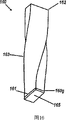
图17为2∶1光学歧管的截面图。Figure 17 is a cross-sectional view of a 2:1 optical manifold.
图18为具有类似于图17的外形的矩形2∶1光学歧管的透视图。FIG. 18 is a perspective view of a rectangular 2:1 optical manifold having an outline similar to FIG. 17 .
图19为具有类似于图17的外形的正方形1∶2光学歧管的透视图。FIG. 19 is a perspective view of a square 1:2 optical manifold having an outline similar to FIG. 17 .
图20A为具有不同输入颜色的3∶1光学歧管的截面图。Figure 20A is a cross-sectional view of a 3:1 optical manifold with different input colors.
图20B为图20A的3∶1光学歧管的另一实施例,LED之间的间隔更大。Figure 20B is another embodiment of the 3:1 optical manifold of Figure 20A with greater spacing between the LEDs.
图21为具有共面输入的4∶1光学歧管的截面图,每一输入具有一个角旋转器。Figure 21 is a cross-sectional view of a 4:1 optical manifold with coplanar inputs, one angular rotator per input.
图22为另一具有共面输入的4∶1光学歧管的截面图,每一输入具有两个角旋转器。Figure 22 is a cross-sectional view of another 4:1 optical manifold with coplanar inputs, each with two angle rotators.
图23为4∶1光学歧管的另一实施例的截面图,具有用于浸入的输入的角压缩器。Figure 23 is a cross-sectional view of another embodiment of a 4:1 optical manifold with an input angle compressor for immersion.
图24为按大约圆弧形状布置的光学歧管的截面图。Fig. 24 is a cross-sectional view of an optical manifold arranged in an approximately circular arc shape.
图25为降低半径的弧上的光学歧管的截面图。Figure 25 is a cross-sectional view of the optical manifold on an arc of decreasing radius.
图26A为具有中间角旋转器的2×2∶1光学歧管的透视图。Figure 26A is a perspective view of a 2x2:1 optical manifold with intermediate angular rotators.
图26B为具有图26A中所示中间角旋转器的2×2∶1光学歧管的透视图。Figure 26B is a perspective view of a 2x2:1 optical manifold with the intermediate angular rotator shown in Figure 26A.
图26C为更公然分支的2×2∶1歧管的视图。Figure 26C is a view of a more overtly branched 2x2:1 manifold.
图26D为3×3∶1歧管的视图。Figure 26D is a view of a 3x3:1 manifold.
图27A为4×4∶1分支的光学歧管的透视图。Figure 27A is a perspective view of a 4x4:1 branched optical manifold.
图27B为图27A中所示的4×4∶1分支的光学歧管从另一角度看的透视图。Figure 27B is a perspective view of the 4x4:1 branched optical manifold shown in Figure 27A from another angle.
图28A为4×4∶1绞扭分支光学歧管的透视图。Figure 28A is a perspective view of a 4x4:1 twisted branch optical manifold.
图28B为图28A中所示的4×4∶1绞扭分支光学歧管从另一角度观看的透视图。Figure 28B is a perspective view of the 4x4:1 twisted branched optical manifold shown in Figure 28A viewed from another angle.
图29为任意分支的光学歧管的另一实施例的透视图。Figure 29 is a perspective view of another embodiment of an optionally branched optical manifold.
图30为亮度移动器的透视图。Fig. 30 is a perspective view of a brightness shifter.
图31A为定义单片光束扩展量挤压器(etendue-squeezer)的光学歧管的另一实施例的分解透视图。31A is an exploded perspective view of another embodiment of an optical manifold defining a monolithic etendue-squeezer.
图31B为图31A的分解图中所示的单片光束扩展量挤压器合成后的透视图。Figure 31B is a composite perspective view of the monolithic etendue squeezer shown in the exploded view of Figure 31A.
图31C为图31A和31B中所示的单片光束扩展量挤压器的另一透视图。31C is another perspective view of the monolithic etendue squeezer shown in FIGS. 31A and 31B.
图32为单片9∶1光束扩展量挤压器的透视图。Figure 32 is a perspective view of a monolithic 9:1 etendue squeezer.
图33A为具有光学无活性表面的亮度传输管道的截面图。33A is a cross-sectional view of a brightness delivery duct with an optically inactive surface.
图33B为与图33A实施例类似的角旋转亮度管道的截面图。Figure 33B is a cross-sectional view of an angularly rotated luminance duct similar to the embodiment of Figure 33A.
图34为具有对称放置的端口的角旋转亮度管道的截面图。Figure 34 is a cross-sectional view of an angularly rotated brightness duct with symmetrically placed ports.
图35为具有无活性表面的4∶1管道的截面图。Figure 35 is a cross-sectional view of a 4:1 conduit with an inactive surface.
图36为具有两个无活性表面的双向对称管道的截面图。Figure 36 is a cross-sectional view of a bidirectionally symmetric conduit with two inactive surfaces.
图37A为合成系统的截面图,其包括四个具有图35结构的结合管道。FIG. 37A is a cross-sectional view of a synthesis system including four combined conduits having the structure of FIG. 35 .
图37B为另一合成系统中的光学歧管的另一实施例的截面图。Figure 37B is a cross-sectional view of another embodiment of an optical manifold in another synthesis system.
图37C为合成系统中光学歧管的另一实施例的截面图,还包括涂覆磷光体的表面。37C is a cross-sectional view of another embodiment of an optical manifold in a synthesis system, also including phosphor-coated surfaces.
图38A为照明另一CPC的电介质CPC的截面图。38A is a cross-sectional view of a dielectric CPC illuminating another CPC.
图38B为图38A的另一结构的截面图。38B is a cross-sectional view of another structure of FIG. 38A.
图39A为包括电介质CPC的另一光学歧管的截面图,其示出了以90°连接两个CPC的缺点。Figure 39A is a cross-sectional view of another optical manifold including a dielectric CPC showing the disadvantage of connecting two CPCs at 90°.
图39B为包括两个如图39A中那样的电介质CPC的另一光学歧管的截面图,其示出了气隙怎样防止射线漏出。Figure 39B is a cross-sectional view of another optical manifold comprising two dielectric CPCs as in Figure 39A, showing how an air gap prevents radiation from leaking out.
图40为利用磷光体反向发射的交替结构的截面图。Figure 40 is a cross-sectional view of an alternating structure utilizing phosphor back emission.
图41为如图40那样的另一交替结构的截面图,还包括涂覆磷光体的表面。Fig. 41 is a cross-sectional view of another alternate structure as in Fig. 40, further including phosphor-coated surfaces.
图42为图41的另一交替结构的截面图,还包括涂覆磷光体的表面。42 is a cross-sectional view of another alternate structure of FIG. 41, further including phosphor-coated surfaces.
图43为图42的自由空间版的截面图,还包括涂覆磷光体的表面。Figure 43 is a cross-sectional view of the free-space version of Figure 42, also including the phosphor-coated surface.
图44为将组合器添加到图43的交替结构的截面图,还包括涂覆磷光体的表面。Figure 44 is a cross-sectional view of the alternate structure with a combiner added to Figure 43, also including a phosphor-coated surface.
图45为交替结构的截面图,其包括带有一个光源(不是三个)的折射输出区的正交三色自由空间组合器,以提供多波长输出。Figure 45 is a cross-sectional view of an alternate structure comprising an orthogonal three-color free-space combiner with refractive output regions of one light source (instead of three) to provide multi-wavelength output.
图46为交替结构的截面图,其包括如图45中的正交组合器以提供多波长输出,但具有四棱镜滤光片结构。Figure 46 is a cross-sectional view of an alternate structure comprising a quadrature combiner as in Figure 45 to provide a multi-wavelength output, but with a quadrangular prism filter structure.
图47为提供多波长输出的交替结构的截面图,其包括具有窄角输出的正交棱镜组合器。Figure 47 is a cross-sectional view of an alternate structure providing multi-wavelength output including a cross prism combiner with narrow angle output.
图48为示出具有窄角输出的平行三色组合器的交替结构的截面图。Figure 48 is a cross-sectional view showing an alternate configuration of a parallel three-color combiner with a narrow-angle output.
图49为包括具有输出区n倍于一输入的自由空间平行组合器的交替结构的截面图。Figure 49 is a cross-sectional view of an alternate structure comprising a free-space parallel combiner having an output area n times larger than an input.
图50为可用于结合多个不同颜色LED以提供多波长光输出的交替结构的截面图,包括具有两个横向CPC的棱镜组合器。Figure 50 is a cross-sectional view of an alternate structure that can be used to combine multiple differently colored LEDs to provide multi-wavelength light output, including a prism combiner with two lateral CPCs.
图51A为包括具有三个平行布置的横向CPC的棱镜组合器的交替结构的截面图,以结合光并提供多波长光输出。51A is a cross-sectional view of an alternating configuration comprising a prism combiner with three transverse CPCs arranged in parallel to combine light and provide multi-wavelength light output.
图51B为歧管的截面图,其使用不同颜色的LED和涂覆磷光体的表面产生多波长输出。Figure 5 IB is a cross-sectional view of a manifold that produces multi-wavelength output using different colored LEDs and a phosphor-coated surface.
图51C为歧管的交替结构的截面图,其使用不同颜色的LED和涂覆磷光体的表面产生多波长输出。Figure 51C is a cross-sectional view of an alternating configuration of a manifold that produces multi-wavelength output using different colored LEDs and phosphor-coated surfaces.
图52为包括两倍宽度亮度移动器的光学歧管的交替结构的截面图。52 is a cross-sectional view of an alternate configuration of an optical manifold including a double-width brightness shifter.
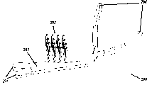
图53A为三重光学歧管的平面图。Figure 53A is a plan view of a triple optical manifold.
图53B为图53A的三重光学歧管的侧视图。Figure 53B is a side view of the triple optical manifold of Figure 53A.
图54A为从图53A和53B的歧管发射的远场强度的等值线图。Figure 54A is a contour plot of far-field intensity emitted from the manifold of Figures 53A and 53B.
图54B为从图53A和53B的歧管发射的远场强度图的中心水平和垂直面。Figure 54B is the central horizontal and vertical planes of a plot of far-field intensity emitted from the manifold of Figures 53A and 53B.
图55为来自图53A和53B的歧管的输出面的空间输出的等值线图。Figure 55 is a contour plot of the spatial output from the output face of the manifold of Figures 53A and 53B.
图56A为三重光学歧管的另一实施例的透视图,连同电路板上的三个输入LED。Figure 56A is a perspective view of another embodiment of a triple optical manifold, along with three input LEDs on a circuit board.
图56B为图56A的光学歧管的透视图,还包括自由形态射束成形透镜。56B is a perspective view of the optical manifold of FIG. 56A, further including a freeform beam shaping lens.
图56C为图56B的光学歧管和射束成形透镜的透视图,以及其照在射束成形反射器上的输出的射线跟踪。Figure 56C is a perspective view of the optical manifold and beam shaping lens of Figure 56B, and a ray trace of its output impinging on the beam shaping reflector.
图57为包括四个如图56C中所示结构的透视图,例如形成完成指示的汽车灯。Fig. 57 is a perspective view including four structures as shown in Fig. 56C, such as a car light forming a completion indicator.
图58A为用于产生射束亮度图形状的出口孔的非对称歧管的透视图,其符合汽车前灯照明要求。FIG. 58A is a perspective view of an asymmetric manifold used to create exit holes in the shape of a beam intensity pattern, which meets automotive headlight lighting requirements.
图58B为图58A的非对称歧管的另一透视图。Figure 58B is another perspective view of the asymmetric manifold of Figure 58A.
在几个图中,同一附图标记指同一组件。In several figures, the same reference numeral refers to the same component.
具体实施方式Detailed ways
本发明将在下面结合附图进行描述,其中同一附图标记代表相同或相似的元件。The present invention will be described below with reference to the accompanying drawings, wherein the same reference numerals represent the same or similar elements.
术语和缩写词表Glossary of terms and abbreviations
下述术语和缩写词用于具体实施方式的整个描述中:The following terms and abbreviations are used throughout the description of specific embodiments:
角旋转器 将亮度从一平面传送到另一倾斜于第一平面的设备Angle rotator transfers brightness from one plane to another device inclined to the first plane
CEC 复合椭圆形集中器CEC Composite Oval Concentrator
CPC 复合抛物线形集中器CPC Compound Parabolic Concentrator
交叉CPC 在两个正交方向具有二维CPC外形的三维结构Intersecting CPC A three-dimensional structure with two-dimensional CPC shapes in two orthogonal directions
二向色滤光片 具有两个不同的传输峰值的滤光片Dichroic filter A filter with two different transmission peaks
LED的圆顶 由透明介质材料制成的、近似球状的LED罩The dome of the LED is a spherical LED cover made of transparent dielectric material
边缘光线原理 非成像光学的基本原理,藉此来自孔边缘的规定的光Edge ray principle Fundamental principle of non-imaging optics whereby defined light from the edge of a hole
线集被保证传送到另一孔的边缘,但第一孔不被成像Linesets are guaranteed to travel to the edge of another hole, but the first hole is not imaged
在第二孔上On the second hole
光束扩展量 熵的光学表示,定义为源面积As和源的输出的投影立Etendue An optical representation of entropy, defined as the projected cube of the source area A s and the output of the source
体角的积乘以包围源的光学介质的折射率n的平方The product of the volume angle times the square of the refractive index n of the optical medium surrounding the source
ITO 铟锡氧化物ITO Indium Tin Oxide
LED 发光二极管,将低压直流转换为窄的光谱带中的光的LED Light-emitting diodes, which convert low-voltage direct current into light in a narrow spectral band
直流转换器
照明器 20世纪的新语,代替19世纪使用的“发光体”,用illuminator 20th-century Newspeak, replacing the 19th-century use of "luminous body," with
以描述光源及功能上相关的光控制装置,如反射器或to describe light sources and functionally related light control devices such as reflectors or
灯罩Lampshade
亮度移动器 将亮度传送到不同横向坐标的设备Brightness Mover Transfers brightness to devices with different horizontal coordinates
磷光体 响应于外部激发而发光的光致发光材料,通常在激发Phosphor A photoluminescent material that emits light in response to an external excitation, usually
中止后仍继续Continue after abort
PMMA 聚甲基丙烯酸甲酯,透明丙烯酸塑料的聚合物成分PMMA Polymethylmethacrylate, a polymer component of transparent acrylic plastics
RIIR透镜 具有指定顺序的折射(R)和内部反射(I)表面的透RIIR lenses have a specified order of refractive (R) and internally reflective (I) surface transmission
镜系统Mirror system
SMS 产生双表面光学设备的光学设计方法,所述光学设备SMS produces an optical design method for dual-surface optical devices that
将两个指定的输入波前变换为两个指定的输出波前,Transforms two specified input wavefronts into two specified output wavefronts,
如美国专利申请10/269,479、10/880,386和美国专 Such as
利6,639,733、6,867,929中公开的那样As disclosed in patents 6,639,733 and 6,867,929
薄膜LED 包括非常薄的层且从其顶面发射其几乎100%的放射Thin-film LEDs consist of very thin layers and emit almost 100% of their radiation from their top surface
线的LEDWired LEDs
TIR 全内反射TIR Total Internal Reflection
波前 传播电磁场中的固定相表面Wavefront Propagating Stationary Phase Surface in Electromagnetic Field
概述overview
为说明的目的,“光学歧管”类似于引擎的排气歧管。在光学歧管中,提供了多个通道,其或将多个光输出结合为单一输出,或将单一输出跨空间分配。该术语可指光纤扇入和扇出设备,如Simmons等人的美国专利6,850,684、6,847,774、6,832,032、6,655,848、6,556,754和6,549,710中所公开的。这种多输入、多输出功能是不同于照明的有效分布的信息任务。在光纤说法中,这样的分布有时称为“扇入”和“扇出”,表示将几个光程连接为一个。For purposes of illustration, an "optical manifold" is similar to an engine's exhaust manifold. In an optical manifold, multiple channels are provided which either combine multiple light outputs into a single output or distribute a single output across space. The term may refer to fiber optic fan-in and fan-out devices, as disclosed in US Patents 6,850,684, 6,847,774, 6,832,032, 6,655,848, 6,556,754, and 6,549,710 to Simmons et al. This multiple-input, multiple-output functionality is distinct from the efficiently distributed information tasks of lighting. In fiber optic parlance, such distributions are sometimes referred to as "fan-in" and "fan-out", denoting the connection of several optical paths into one.
当考虑可逆性时,“扇入”和“扇出”之间的区别非常重要。也就是说,一些这样的光纤设备在功能上不能互换,因为在反向光程上的一些光可能散开并在内部损耗。然而,具有能可逆传送光的系统是有利的,从而其实施可用于两个方向。因而,在此描述的光学歧管的实施例可用于两种光分布:从高功率源到应用的多点及将许多源光结合为一个大的、与其输入源具有相同亮度的合成源。The distinction between "fan-in" and "fan-out" is important when considering reversibility. That is, some such fiber optic devices are not functionally interchangeable because some of the light on the reverse optical path may spread out and be lost internally. However, it would be advantageous to have a system that transmits light reversibly so that its implementation can be used in both directions. Thus, the embodiments of the optical manifold described herein can be used for both light distributions: from high power sources to multiple points of application and combining many source lights into one large composite source with the same brightness as its input source.
术语“光学歧管”已由Campbell等人用在美国专利4,362,361中,但在那里该术语指部分反射涂层,当其在板内挖通道时其重复允许小部分激光束逃避反射,从而多个光束被合成一个光束。这种使用不同于传统意义上的使用,因为“光学歧管”现在指分支多对一光程。The term "optical manifold" has been used by Campbell et al. in U.S. Patent 4,362,361, but there the term refers to a partially reflective coating whose repetition allows a small portion of the laser beam to escape reflection as it tunnels into the plate, thereby allowing multiple The beams are combined into one beam. This usage differs from usage in the traditional sense, as "optical manifold" now refers to branching many-to-one optical paths.
美国专利6,186,650公开了分支光波导的“光学歧管”,并说明了几个实施例。然而,可以认为这些结构的实际光线跟踪有相当的分散,如该专利的图19A和图19B所示。此外,可以相信,该现有技术的光束扩展量不守恒,其输出大大弱于输入。这是因为端口的弄成方形的终端将导致在那里导向的光的大部分将向后反射。US Patent 6,186,650 discloses an "optical manifold" of branched optical waveguides and illustrates several embodiments. However, it is believed that the actual ray tracing of these structures has considerable dispersion, as shown in Figures 19A and 19B of that patent. Furthermore, it is believed that the etendue of this prior art is not conserved, the output being much weaker than the input. This is because the squared termination of the port will cause a large portion of the light directed there to be reflected back.
光束扩展量,与熵类似,是光学无序的度量,其基本上等于空间范围和角范围的积。增加光的光束扩展量可被认为是将功变为废热的光学等价行为,其中光学功是发光亮度,废热是该光的无用分散。一旦不可避免的反射和散射被引起时,“光束扩展量受限的”光学设备以几乎最初的亮度传送光。在此描述的光学变换器是光束扩展量受限的变换器,因为输入面积-角乘积被保留用于通过其的光。在此描述的光学变换器的一些实施例从多个源接收光以产生大的、高度均匀的合成源,其将证明在照明领域中非常有用。其它实施例将形成分布式照明系统,如车辆仪表板,其既保持光度又保持光束扩展量,使得在完成照明任务时只需要较少的LED光源。Etendue, like entropy, is a measure of optical disorder that is essentially equal to the product of spatial extent and angular extent. Increasing the etendue of light can be thought of as the optical equivalent of converting work, where the optical work is the brightness of the light emitted, and waste heat, the useless dispersion of that light, into waste heat. "Etendue limited" optics deliver light at nearly its original brightness once the inevitable reflections and scattering are induced. The optical transducer described here is an etendue-limited transducer because the input area-angle product is preserved for light passing through it. Some embodiments of the optical transducers described herein receive light from multiple sources to produce a large, highly uniform composite source, which will prove very useful in the field of lighting. Other embodiments would form a distributed lighting system, such as a vehicle dashboard, that maintains both luminosity and etendue such that fewer LED sources are needed to complete the lighting task.
光束扩展量受限的光学元件的一个例子是复合抛物线形集中器(CPC),由Winston在美国专利4,002,499中公开。另一例子是复合椭圆形集中器(CEC),由Winston在美国专利3,957,031中公开。这两种集中器均可用作在此描述的光学变换器的构件。最近的例子是Fein在美国专利6,819,687中公开的角转向元件,其仅在角度在临界角之下时才是光束扩展量有限的(NA<1)。设计来与光纤照度的角限制一起使用,该设备具有非常大的局限性,而在此描述的光学变换器的、与其外表类似但几何结构不同的角转向部件远优胜过该设备。Fein的设备为NA=0.5范围的光纤照度,从而当光在NA=1中时,光将漏出该设备(NA=1是在此描述的光学变换器的范围。)在此描述的光学变换器具有NA=1的范围,因为这使其能够传送四倍于NA=0.5系统如Fein的系统的辐照度。Fein的设备的另一局限在于其设计极限是NA=1,因为其主要应用是生物医学设置中的直角转向,对此,在NA=0.5时使用两个45°旋转器。相反,在此描述的光学变换器的实施例的角旋转部件在N=1的任何转向角其传送的光具有非常小的漏光,从而在此说明的90°角旋转器很容易扩展到包括适于螺旋形结构的360°设备,如果这样的新需求出现的话。这种灵活性使在此描述的光学变换器实施例能够用于跨光结合和光分布的整个应用,且具有最大通量,某些东西仍由现有技术完成。这种灵活性还由在此描述的光学歧管的实施例例证,其包括两个相对的、用作亮度移动器的角旋转器,系统的另一有用的元件可任意分支分布式照明的图案。An example of an etendue limited optical element is the compound parabolic concentrator (CPC), disclosed by Winston in US Patent 4,002,499. Another example is the compound elliptical concentrator (CEC), disclosed by Winston in US Patent 3,957,031. Both types of concentrators can be used as components of the optical converters described herein. A recent example is the angle steering element disclosed by Fein in US Patent 6,819,687, which is etendue limited (NA<1) only for angles below the critical angle. Designed to be used with angular confinement of fiber optic illumination, the device is far superior to the angularly similar but geometrically different angular steering components of the optical converter described here, which have very limited limitations. Fein's device is fiber illumination in the range of NA = 0.5 such that when light is in NA = 1, light will leak out of the device (NA = 1 is the range for the optical converter described here.) The optical converter described here There is a range of NA = 1 as this enables it to deliver four times the irradiance of a NA = 0.5 system such as Fein's. Another limitation of Fein's device is that its design limit is NA = 1, since its main application is quarter steering in biomedical settings, for which two 45° rotators are used at NA = 0.5. In contrast, the angular rotators of embodiments of the optical transducers described herein transmit light with very little light leakage at any turning angle of N=1, so that the 90° angular rotators described herein are easily extended to include suitable 360° equipment based on the helical structure, if such a new demand arises. This flexibility enables the optical converter embodiments described herein to be used throughout applications across light combining and light distribution with maximum throughput, something still accomplished by prior art. This flexibility is also exemplified by the embodiment of the optical manifold described here, which includes two opposing angular rotators that act as brightness shifters, another useful element of the system to arbitrarily branch patterns of distributed illumination .
在此提供的另一改进涉及光学变换器的可制造性。在现有技术中,如Fein例示的技术,所有表面必须旋光作用在所述光学角转向设备上。这使其很难在不损害旋光作用表面的情况下具有注入点。在此描述的光学变换器通过沿设备的长度方向提供无旋光表面而克服了该问题,所述无旋光表面可用于注入点。无旋光表面可用作保持设备的手段,且它们可自由地修改为各种形状,而不会影响设备的旋光表面的形状。无旋光表面由角旋转器内的光线分布图故意产生,提供与光场的无相互作用包封,在其内可制造无损附属装置。Another improvement provided herein relates to the manufacturability of optical transducers. In the prior art, as exemplified by Fein, all surfaces must be optically active on the optical angle turning device. This makes it difficult to have injection points without damaging the optically active surface. The optical transducers described herein overcome this problem by providing optically inactive surfaces along the length of the device that can be used for injection points. Optically inactive surfaces can be used as a means of holding the device, and they can be freely modified into various shapes without affecting the shape of the optically active surface of the device. The optically inactive surface is intentionally created by the light distribution pattern within the angular rotator, providing an interaction-free encapsulation with the optical field within which lossless attachments can be fabricated.
描述describe
通过参考下面对本发明及附图的详细描述可更好地理解在此描述的光学变换器的特征和优点。下面的描述提出了其中使用本发明原理的例证性实施例。The features and advantages of the optical transducers described herein may be better understood by reference to the following detailed description of the invention and accompanying drawings. The following description presents illustrative embodiments in which the principles of the invention are employed.
在此描述的光学歧管从多个固态源接收光并将其结合为具有和输入总和一样的光束扩展量的、单一虚拟源输出。当光源具有不同的主波长时,输出光具有其比色混合物的色度。由于光的可逆性,同样形状的歧管可用于将来自单一大固态光源的光在在多个虚拟源之间分散。The optical manifold described herein receives light from multiple solid-state sources and combines it into a single, virtual source output with the same etendue as the sum of the inputs. When the light sources have different dominant wavelengths, the output light has the chromaticity of their colorimetric mixture. Due to the reversibility of light, a manifold of the same shape can be used to disperse light from a single large solid-state light source among multiple virtual sources.
具体地,两种固态光源用于在此描述的光学变换器:薄LED和圆顶封装的高功率LED。它们的封装几何结构意味着不同的注入装置结构用于在此描述的光学变换器。现有技术包括几种类型的注入器装置,包括CPC和浸没透镜,以及传统的圆顶封装。Specifically, two solid-state light sources were used in the optical converters described here: thin LEDs and dome-encapsulated high-power LEDs. Their packaging geometries imply different injector configurations for the optical converters described here. The prior art includes several types of injector devices, including CPCs and immersion lenses, as well as conventional globular packages.
图1A为包括薄膜式LED10的光学歧管的截面图,LED10包括发光层11、反射装置12和窗口13。LED10嵌入在保护性透明环氧树脂14中。外部的CPC反射器15准确地位于环氧树脂14的表面上,从而其正好跨在LED10上方的窗口13上,通常为1mm的跨越。在此描述的光学歧管的一个优点在于其允许较大(或多个)LED的更有效的冷却。冷却较大或多个芯片的困难在于在此描述的光学变换器的动机之一。(电气和热量排除装置未示出。)FIG. 1A is a cross-sectional view of an optical manifold comprising a thin-
薄膜式LED,如图1A中所示的LED10,从器件的上表面发射其几乎100%输出通量。这样的器件已在实验室中制造出来,并已为公众所知,如德国Regensburg的OSRAM半导体公司,其在2005年年中已开始商业化生产红、黄、绿、蓝LED。目前,加利福尼亚州San Jose的OSRAM公司提出了多种薄膜式发射器技术,包括磷化铟镓铝(INGaAlP)和氮化铟镓(InGaN)。OSRAM半导体公司迄今为止示出的所有发射体系结构均在其上表面上使用丝焊。目前这些器件中的发射层厚度在0.1微米级且整个芯片深度在2-5微米。因此,自这些器件的侧向发射非常小,从而它们可理想地适于用于本发明的许多实施例。Thin-film LEDs, such as
图1A还示出了发射边缘射线16的源点11s,其正好通过CPC15的上边缘。同样还示出了水平发射的边缘射线17e,从而截接反射器15的底部,其从底部反射入射线17r中,之后其正好通过CPC15的上边缘。所示为45°设计角。其应用于直接射线16和反射线17r。双箭头18指由CPC15产生的虚拟源的宽度。该宽度为发射层11的宽度的1/sin 45°倍,从而保持光束扩展量。FIG. 1A also shows
尽管图1A所示CPC15为中空金属反射器,其也可填充以电介质如铸入环氧树脂。如果45°设计角被稍微降低到临界角(40°),CPC将变为略高于45°设计角的情形,因跨CPC15顶部的平面大气干扰,极端射线16和17r将被折射到水平方向。这样的填充的CPC将以等于透明填充材料的折射率的横向放大率使LED与空气连接。(面积增加n2因子。)对于更大的放大率,需要更窄的设计角。当该角度降低到时10°,由于全内反射足够,将无需反射器15,如图2中所示。Although the
Berg和Saul的美国专利3,739,217示教了从高折射率体内引出光可通过使高折射率层的前发射表面或后表面粗糙而得以增加,该粗糙后的后表面与反射层相接。然而,Berg等的专利既未指出反射器材料也未指明反射器是否应与高折射率体的所有表面直接接触。Berg等的专利似乎在图2和3中指示在图示的体和后反射器之间有气隙。US Patent 3,739,217 to Berg and Saul teaches that light extraction from a high index volume can be increased by roughening the front emitting surface or the back surface of the high index layer, the roughened back surface being in contact with the reflective layer. However, the Berg et al. patent neither specifies the reflector material nor whether the reflector should be in direct contact with all surfaces of the high index body. The Berg et al. patent appears to indicate in FIGS. 2 and 3 that there is an air gap between the illustrated body and the rear reflector.
图1B为LED10的放大图,其示出发射层11包括位于中间的薄活性层11a(大约0.1微米)、在其上部的InGaN层11u、和在其下部的层11b。窗口13具有倾斜角13w以防止光漏出。图1B还示出了提高上发射LED(或主要采取上发射的LED)的发光引出效率的方法,其中导电反射层12还用于向外延层11供电,由此其为直接接触。粗糙表面11i为接触表面。所述粗糙化可通过化学刻蚀或其它公知方法在外延层11上进行。一旦外延层被粗糙化,反射层12可通过真空、溅射或其它沉积方法沉积于其上。1B is an enlarged view of
反射层12的材料特性必须准确地指定以与外延层的特性匹配。例如,当需要导电反射层的情况下,金属材料是最佳选择,但其折射率必须具有适当的复值以获得高漫反射比。例如,对于使用GaInN或GaN外延层的蓝光LED,GaInN和GaN的可见波长折射率为约2.54。计算这样的金属层的反射比包括在费涅反射等式中使用复折射率,使得候选材料的折射率的实数和虚数部分均为临界值。以零入射角入射的射线的反射比可提供用于选择适当材料的度量。实现所述分析的适当等式为:The material properties of the
其中in
R为在外延和金属层的分界面零入射的反射比;R is the reflectance of zero incidence at the interface between the epitaxial layer and the metal layer;
Nepi为外延层的折射率;N epi is the refractive index of the epitaxial layer;
Ns为金属折射率的实数部分;及N s is the real part of the metal's refractive index; and
ks为金属折射率的虚数部分。k s is the imaginary part of the refractive index of the metal.
假设外延层具有2.54的折射率,金属需要低实数部分和高虚数部分。银在从450nm(k=2.47)到700nm(k=4.52)的波长范围具有低的实数部分(0.12)和非常高的虚数部分。在550nm时,厚的银层具有约0.12的折射率(实数)和3.34的虚数值。将这些值带入前述等式得出0.93的反射比。作为比较,铝层在与GaIN接触时具有低得多的反射比,因为其在550nm时具有0.76的实数值和5.32的虚数值。这样,对于零入射角射线,在两种材料的分界面的反射比可用同一等式计算为0.80。这是非常大的区别,特别是对于与该层的反射比具有非线性关系的器件的引出效率,因为外延内的内部射线在或被吸收或从外延层引出之前经历许多边界反射。因此,该底部分界层的反射比的小改善可在LED的外量子效率方面产生大的改善。Assuming the epitaxial layer has a refractive index of 2.54, the metal requires a low real part and a high imaginary part. Silver has a low real part (0.12) and a very high imaginary part in the wavelength range from 450 nm (k=2.47) to 700 nm (k=4.52). At 550 nm, a thick silver layer has a refractive index (real number) of about 0.12 and an imaginary value of 3.34. Plugging these values into the preceding equation yields a reflectance of 0.93. In comparison, the aluminum layer has a much lower reflectance when in contact with GaIN as it has a real value of 0.76 and an imaginary value of 5.32 at 550 nm. Thus, for rays at zero angle of incidence, the reflectance at the interface of the two materials can be calculated to be 0.80 using the same equation. This is a very large difference, especially for the extraction efficiency of devices that have a non-linear relationship to the reflectance of the layer, since internal rays within the epitaxy undergo many boundary reflections before either being absorbed or extracted from the epitaxial layer. Thus, a small improvement in the reflectance of the bottom interface layer can yield a large improvement in the external quantum efficiency of the LED.
这样的反射层也可使用多层方法用介质材料制成,特别是工业通用的Bragg反射器。然而,为向半导体供电,称为vias的导电通路必须通过该非传导层引入在某一地方。然而,介质层的使用可增加器件的内阻因而增加给定施加电压产生的内部热量。此外,大家都知道很难设计对大范围波长和入射角均具有高反射比的Bragg反射器。这对于在管芯上采用保形磷光体涂覆的LED更是问题。因此,银可被视为优于介质反射器的解决方案,因为其在大范围的入射角和波长的情况下均表现良好。Such reflective layers can also be made of dielectric materials using multilayer methods, in particular Bragg reflectors which are common in the industry. However, to provide power to the semiconductor, conductive pathways called vias must be introduced somewhere through this non-conductive layer. However, the use of a dielectric layer can increase the internal resistance of the device and thus increase the internal heat generated for a given applied voltage. Furthermore, it is known that it is difficult to design Bragg reflectors with high reflectance over a wide range of wavelengths and angles of incidence. This is even more of a problem for LEDs employing conformal phosphor coatings on the die. Silver can therefore be considered a superior solution to dielectric reflectors as it performs well over a wide range of incidence angles and wavelengths.
美国专利6,784,462示教了怎样通过在银层前面组合四分之一波长的氧化铟锡(ITO)层而制造用于LED的、具有非常高反射比的“全向”后反射器。然而,在’462专利中的薄膜方法假设银和ITO层是光滑的,排除了LED底部即“外延层”的任何适当粗糙,因为其通过真空中的原子束制造在衬底的上面。由于高折射率材料立方体内的广泛光陷阱,标准LED几何结构,要实现最大引出效率,其必须在反射器与外延层接触的分界面具有粗糙表面。这是实现高漫反射比所需要的,其使得捕集的光将被任意改方向从而有另一机会漏出。此外,ITO较银具有低得多的电导,这对于某些设计而言是一个缺点。US Patent 6,784,462 teaches how to make a very high reflectance "omnidirectional" back reflector for LEDs by combining a quarter wave layer of indium tin oxide (ITO) in front of a silver layer. However, the thin-film approach in the '462 patent assumes that the silver and ITO layers are smooth, precluding any appropriate roughness of the bottom, "epilayer" of the LED as it is fabricated on top of the substrate by atomic beam in vacuum. Due to the extensive light trapping within the cube of high-index material, standard LED geometries, to achieve maximum extraction efficiency, must have a rough surface at the interface where the reflector meets the epitaxial layer. This is required to achieve a high diffuse reflectance such that trapped light will be redirected arbitrarily to have another chance to escape. In addition, ITO has a much lower conductance than silver, which is a disadvantage for some designs.
使捕集的光被吸收之前散射出去需要或底部漫射器或顶部散射层与图1A的层11u合并。也可使用两种方法的结合。然而,当同时使用顶部和底部散射层因而降低器件的引出效率时,会在器件中引入太多的散射。可见,如果不在层11u内引入顶部散射,如美国专利6,784,462中描述的完美反射器将不如在此描述的银漫反射器。此外,在许多情况下,希望在层11u的顶部具有光滑分界面,因而不能在其分界面或其顶部发射表面的下面引入散射或漫反射层。在这些情况下,后部漫反射器证明最有利并已在此叙述,其将胜过甚至100%完美的镜面反射器。Scattering the trapped light before it is absorbed requires either a bottom diffuser or a top scattering layer to be incorporated with layer 11u of Figure 1A. A combination of the two approaches can also be used. However, too much scattering is introduced into the device when both top and bottom scattering layers are used thereby reducing the extraction efficiency of the device. It can be seen that a perfect reflector as described in US Pat. No. 6,784,462 would be inferior to the silver diffuse reflector described here if top scattering were not introduced in layer 11u. Furthermore, in many cases it is desirable to have a smooth interface on top of layer 11u, so it is not possible to introduce a scattering or diffuse reflective layer below its interface or its top emitting surface. In these cases, a rear diffuse reflector proves to be most advantageous and has been described here, which will outperform even a 100% perfect specular reflector.
此外,如果不适当地保护以使其免与空气或腐蚀材料(其很容易与硫反应)接触,银将损耗其反射率,从而其必须用适当的保护层密封。通常,如果银夹在外延层和适当的衬底如锗之间,则不会发生该材料的显著降级,因为其已被气密。如果需要边缘保护,半导体设计领域的技术人员已知有许多适当的材料可使用。Furthermore, silver will lose its reflectivity if not properly protected from air or corrosive materials (which react readily with sulfur), so it must be sealed with a suitable protective layer. Typically, if silver is sandwiched between an epitaxial layer and a suitable substrate such as germanium, no significant degradation of the material will occur since it is already hermetically sealed. If edge protection is desired, there are many suitable materials known to those skilled in the art of semiconductor design that can be used.
关于由银制成的粗糙后反射器的问题,通过使用公知的Monte-Carlo射线跟踪技术对其进行的计算机仿真表明在此描述的光学变换器将因在LED中具有该特征而大大受益,特别是那些在下面公开的重复利用磷光体的发射的实施例中。With regard to the problem of rough back reflectors made of silver, computer simulations of them using the well-known Monte-Carlo ray tracing technique show that the optical converters described here would greatly benefit from having this feature in LEDs, especially are those in the embodiments disclosed below that reuse phosphor emission.
当然,该粗糙的银反射器可大大有利于薄膜式LED,无论是否与在此描述的光学变换器结合使用。再次参考图1B,另一所述LED光学改进是降低下外延层11b的吸收比,其中大部分光度损耗发生在外延层11内。作为外延,该层通常沉积在蓝宝石晶体上。在制造薄膜式LED时,从蓝宝石去除外延晶片。(从蓝宝石衬底去除InGaN晶片所需要的过程的主要内容已由OSRAM-Opto的K.Streubel博士在2004年10月在美国加利福尼亚州圣地亚哥举行的Intertech LED会议上描述。)Of course, the rough silver reflector can greatly benefit thin-film LEDs, whether used in conjunction with the optical converters described herein or not. Referring again to FIG. 1B , another described LED optical improvement is to reduce the absorptivity of the
下层的吸收对其功能而言不是必须的,似乎限于表面原子晶面,与该层的5000nm总厚度不相称的几十纳米。根据德国UIm大学的S.Schad和B.Neubert的研究,InGaN型LED的第一薄层生长在蓝宝石衬底上,大约65nm,在蓝光波长时其负责InGaN LED的大部分吸收比。它们推理认为生长在衬底上的其余半导体材料高度透明。这些平面非常靠近蓝宝石从而它们的晶体结构和吸收比大大增加。在一些实施例中,层11a和11u均不具有这种薄的吸收层。可用磁流变抛光准确去除该应变子层,从而大大降低吸收比,进而提高LED的外量子效率。The absorption of the underlying layer is not essential for its function and appears to be limited to surface atomic facets, a few tens of nanometers disproportionate to the total thickness of this layer of 5000 nm. According to the research of S. Schad and B. Neubert of UIm University in Germany, the first thin layer of InGaN type LED is grown on the sapphire substrate, about 65nm, which is responsible for most of the absorption ratio of InGaN LED at the blue wavelength. They reasoned that the remaining semiconductor material grown on the substrate was highly transparent. These planes are very close to the sapphire so that their crystal structure and absorption ratio are greatly increased. In some embodiments, neither
提高该效率的另一可能是导致图1B的前端层11u具有体积散射特征,而不是典型的完全透明。使用射线跟踪模型的研究表明将100/mm的散射系数引入层11u将使得SMD型LED的效率增加大约40%,其中层11u没有任何明显的散射且没有磷光体层与其接触。类似的改善也可在圆顶型单色LED中发生。如果散射系数增加到200/mm,只有非常微小的改善。反之,如超过该水平,其达到性能从最大开始降级的点。当与已经描述的粗糙后反射器方法结合使用时,在前端层中应用散射手段通常对性能没有有利影响。如果糙化后反射器与具有10/mm散射系数的层11u结合使用,引出效率只有非常微小的改善。超过该前端散射的水平,性能将低于只使用单一方法的情况。Another possibility to increase this efficiency is to cause the front end layer 11u of Fig. 1B to have volume scattering characteristics, rather than being fully transparent as is typical. Studies using ray tracing models have shown that introducing a scattering coefficient of 100/mm into layer 11u will increase the efficiency of SMD-type LEDs by about 40%, where layer 11u does not have any significant scattering and no phosphor layer is in contact with it. Similar improvements can also occur in dome-type monochrome LEDs. There is only a very slight improvement if the scattering coefficient is increased to 200/mm. Conversely, beyond that level, it reaches a point where performance degrades from maximum. Applying scattering means in the front-end layer generally has no beneficial effect on performance when used in conjunction with the already described rough back reflector approach. If a roughened back reflector is used in combination with a layer 11u having a scattering coefficient of 10/mm, there is only a very slight improvement in extraction efficiency. Beyond this level of front scatter, performance will be lower than if only a single method were used.
当LED的引出效率为高时,在此公开的重获反向散光的光学歧管可被大大增强。具体地,在此描述的远程磷光体实施例在外量子效率方面将优于现有技术,特别是保形磷光体LED。在此公开的新的光学系统当与上部发射或实质上上部发射LED结合使用时其性能将得以大大改善,特别是那些采用具有合适散射的反射背面层的LED。When the extraction efficiency of the LEDs is high, the optical manifolds disclosed herein to recover back-scattering can be greatly enhanced. In particular, the remote phosphor embodiments described herein will outperform the prior art in terms of external quantum efficiency, especially conformal phosphor LEDs. The new optical system disclosed herein will greatly improve its performance when used in conjunction with top-emitting or substantially top-emitting LEDs, particularly those employing a reflective back layer with suitable scattering.
图2A为填充电介质的CPC的底部的截面。如图1A中一样,薄膜式LED10被浸入透明电介质14中。光学上与透明电介质14连续的是填充电介质的CPC20,由CPC表面21形成,其通过全内反射单独工作,因而不需要反射涂层。在实际实施中,CPC20应单独制造并在光学上与透明电介质14连结,刚才上面的薄膜式LED10。Figure 2A is a cross-section of the bottom of a dielectric-filled CPC.
图2B为图2A的填充电介质的CPC的底部的截面,其示出了整个CPC20,具有成形为10°输出角的抛物线形轮廓21,这是CPC仅使用全内反射的最宽可能。轮廓21的上边缘211为虚拟源22的外缘。CPC20内的电介质继续向右而成为另外的实施方式(未在图2中示出),由图5中的CPC54和较大的CPC53例示。Figure 2B is a cross-section of the bottom of the dielectric filled CPC of Figure 2A showing the
在一些实施例中,CPC20的折射率高于包括图1B的透明电介质14的环氧树脂材料的折射率。例如,珠宝级的立体氧化锆具有2.2的折射率,与钻石相似。即使目前其比聚合物塑料光学器件昂贵,这样的高折射率透明材料在将来必将经济可用。其对于形成光学上与薄膜式LED连结的CPC以形成在此描述的光学变换器实施例是有利的。在二氧化钛薄膜的高折射率(~2.5)与LED材料匹配的同时,薄膜的高吸收比使其不适于形成CPC。来自华盛顿红外材料集团的海军研究实验室的溶胶凝胶材料正被开发以进行浇铸或以晶锭形式,其可用折射率为空前的2.4-3高值,足够与LED材料匹配的折射率。另外,这些高折射率材料可被设计和制造以在可见光波长时具有非常低的吸收比系数,与最高光度PMMA材料类似。这可以消除使目前LED困扰的光陷阱和高菲涅耳反射率。图2C为使用这种方法的变化的另一光学歧管的截面图,其中用两个CPC代替CPC20。第一CPC2002与LED2001接触,并由与半导体折射率匹配的溶胶凝胶材料制成,第二、上面的CPC2003由较低折射率材料制成,如PMMA。第一CPC2002设计用于部分校准并全部反射第二CPC2003,CPC2003执行另外的校准。图2C中所示的布置大大增加了来自管芯的通量的全部引出。由此,LED2001在其底部应具有镜面反射层,与图1B的漫反射镜不同。包围硅酮材料2004,具有1.4的低折射率,是用于浇铸CPC2002的初始模子,其后为小的CPC2002提供结构支撑,减轻其与上表面LED2001连接处的应力。CPC2001按折射率比为2.5∶1.4进行设计,完全以全内反射方式工作。其出口面为与较大CPC2003的平界面2005。边缘射线2006R和2006L被示出由CPC2001的上缘反射,之后由分界面2005折射为70°边缘射线2007R和2007L。它们由CPC2003内部反射为最后校准的射线2008R和2008L。与它们相邻的是边缘射线2008E,源自射线2006R和2006L,其通过分界面2005直接折射之后全内反射离开CPC2003的壁。In some embodiments,
图2D为图2C中部分示出的整个CPC2003的截面图,包括边缘射线2008E的最终位置。Figure 2D is a cross-sectional view of the
图2C和2D的器件的另一实施例在LED2001和CPC2002之间的分界面包括薄的、高匹配折射率层。在这种情况下,匹配折射率磷光体层经如电泳沉积方法沉积在LED上。一种方法是在磷光体和LED的上表面之间提供高接触面积的方法。LED2001、小CPC2002和磷光体的折射率应精密匹配,最好在0.1的偏差之内。这样,对于在上部无活性表面具有2.5折射率的InGaN LED,磷光体和小CPC的材料应具有在2.4和2.5之间的折射率。基于该器件的实施例不使用或不需要短通滤光片来象如图10B实施例中所示的短通滤光片105那样为来自LED的反向散光设陷阱。Another embodiment of the device of FIGS. 2C and 2D includes a thin, highly matched index layer at the interface between
图3A为嵌入在圆顶30中的薄LED10的截面图,圆顶为商业封装的典型结构。圆顶30被示为最小的可能大小,对于环氧树脂的折射率(n=1.54),与所有从LED10发射的射线避开全内反射一致。点10d标记LED10的拐角半径。超过该半径,部分射线将不能出到圆顶外面。假想的示例性射线31被内部反射,因为其起点太靠近半球30的表面。Figure 3A is a cross-sectional view of a
图3B为浸入在球形透镜33中的LED10的截面图。几乎水平的边缘射线34e被折射到外部射线34r,其表示30°的偏转。该角度降低对快速光学系统聚集光束是有用的。在实践中,球33应被胶粘到透明衬底14上。由于其象差,这样的透镜将稍微增加光束扩展量。其大于图3A的半球,但其大小被类似地确定,使得其正好允许通过LED10的拐角发射的所有射线能够未经反射的漏出。FIG. 3B is a cross-sectional view of
图3C为电路板37上的薄LED36的截面图,其浸入在环氧树脂团38中,其简明的形状源自环氧树脂十分便于大规模生产的特征。不利的是,其拦住一些光。然而,这种形状与大规模生产十分调和,从而在此描述的光学变换器的其它元件可被成形为与其连结。Figure 3C is a cross-sectional view of a
图4A为棱镜耦合器40的截面图,其具有适于棱镜材料的临界角αc的内角。薄LED41跨气隙41a发送Lambertian发射,其中其被限制在上边缘射线41e和下边缘射线41L之间。薄LED42跨气隙42a发射并进入棱镜40,其中其Lambertian发射变成被限制在角αc的一半以内,在上边缘射线42e和下边缘射线42L之间。内角40A为2αc的目的在射线41e被看见内反射离开气隙42加入射线42L时变得很明显。因此,内部反射的光填充入射光边缘射线外的角度空间。FIG. 4A is a cross-sectional view of a
图4B为使用图4A中所示的棱镜耦合器的光学歧管44的截面图。光学歧管44包括电介质CPC44c和结合棱镜块44b。薄LED45浸入在电介质CPC45c中,其在气隙45a处更宽,跨该气隙将Lambertian光照入歧管44,其中折射将其限制在临界角αc。类似的方法也用于LED46、CPC46c和气隙46a。之后,棱镜耦合器通过45a和46a接收跨越2αc角的两个辐射输入并将它们在44b变为全Lambertian式样(约±90°全角)。CPC44c在块44b处扩大其宽度指到其出口面44a。这使得所有光在Lambertian发射44e时均能退出,从而形成“虚拟芯片”。在44b的出口表面将拦住超过临界角αc的光,从此使用CPC44c。FIG. 4B is a cross-sectional view of an
图5为用于两个LED51和52作为输入的反射光学歧管的截面图,分别具有馈入单一、更大矩形CPC53进行输出的小CPC54和55。这是结合两个发光二极管的输出的简单方式。反射光学歧管50接收第一LED芯片51和第二LED芯片52的光输出。歧管50包括上部复合抛物线形集中器(上部CPC)53和分别接收芯片51和52的光的下部复合抛物线形集中器(下部CPC)54和55。分界线50d描绘CPC53的输入平面和CPC54及55的输出平面。输出开口56将两个LED的结合输出发射到约±90°。Figure 5 is a cross-sectional view of a reflective optical manifold for two
CPC54的运行由边缘射线57示出,其为来自芯片51的几乎水平的射线的曲面法线58附近的反射。在线50d反射之后,边缘射线57到输出开口58的边缘,由虚线的退出线表示,因此其被反射回到水平方向,不幸地,这使得所述虚线稍微不明显。The operation of
在此描述的光学变换器的另外的实施例通过使用图5的聚类抽样原理是可能的,其被建立在图1A的反射器上。图6A到6I的一系列图图示了聚类的另外一些实施例。Further embodiments of the optical transducers described herein are possible by using the cluster sampling principle of Fig. 5, which is built on the reflector of Fig. 1A. The series of diagrams of Figures 6A to 6I illustrate further embodiments of clustering.
图6A为光学歧管610的截面图,其基于如图2中所示的电介质CPC。歧管610包括输入CPC611和612及输出CPC613。LED被安装在入口611L和612L,且它们的结合输出形成在出口613E。分界线610D是输入和输出CPC之间的边界。光的可逆性表明可以是大的LED照入出口613E,并使得光在入口611L和612L发射。FIG. 6A is a cross-sectional view of an
图6B为光学歧管620的截面图,包括输入电介质CPC621和622及更大的输出CPC623。输入CPC621还包括混合棒621M,正好从源621L向内,其具有可能用于引导的光的最小宽度。这有助于消除源621L中的非均匀性,以确保出口623E的均匀亮度。FIG. 6B is a cross-sectional view of an
图6C为光学歧管620的一实施例的截面图,包括电介质CPC输入歧管621和622,及特制的反射镜623,其与透镜表面620S共同用于在出口623E的空气中产生光束扩展量受限的输出。6C is a cross-sectional view of one embodiment of an
图6D为光学歧管的另一实施例630的截面图,包括反射输入锥形体631和632、输出锥形体633、及透镜634。来自LED631L和632L的光在输出端口633E结合。6D is a cross-sectional view of another embodiment of an
图6E为光学歧管的另一实施例640的截面图,包括反射输入反射镜641和642,输出反射镜643、及菲涅耳透镜644。来自LED641L和642L的光在输出端口643E结合。为了清晰,菲涅耳透镜644的厚度被放大,在实际实施中可能更薄。6E is a cross-sectional view of another embodiment of an
图6F为光学歧管的另一实施例650的截面图,包括输入TIR透镜651和652及输出TIR透镜653。输入LED651L和652L使其输出在聚焦区653E结合。图6A-6E的界面可以矩形或圆形几何结构体现。然而,TIR透镜为内在圆形对称,需要对它们进行一些修整以镶嵌为阵列。6F is a cross-sectional view of another embodiment of an
图6G为复合透镜660的平面图,包括55个六边形、修整的、圆形对称输入装置,如图6A-6F例示的装置。每一透镜661聚焦在LED662上。Figure 6G is a plan view of a
图6H为自光学歧管670的输入侧的透视图,包括7个圆形TIR透镜671,每一透镜集中在LED672上并接收其光。Figure 6H is a perspective view from the input side of an
图6I为图6H的光学歧管670自其另一侧的透视图,示出了输出TIR透镜673和出口区673E。Figure 61 is a perspective view of the
一旦本发明的原理被理解,前述元件的许多其它组合可进行明确地表达。例如,图6A中的大输出电介质CPC610可用图6F的大的修整后的TIR透镜653代替。在这种情况下,输出图象被形成在空气中。该后面的结构具有优点,因为整个光学系统在长度上更短且在某些情况下,TIR透镜较长的CPC或交叉CPC更容易铸模,成本更低。Many other combinations of the foregoing elements may be expressed once the principles of the invention are understood. For example, the large
在所有上面的结构中,组件或可被铸模为单独的件然后连结在一起,或可被铸模为一件。In all of the above configurations, the components can either be molded as separate pieces and then joined together, or they can be molded as one piece.
迄今为止,所示的实施例已使用薄LED为输入源,且许多实施例依赖于靠近发射芯片。在如图3A所示的实施例中,圆顶仅可由图6H的TIR透镜用作输入。将亮度从圆顶引出并将其成像在空气中是必要的,当然,在芯片浸入在折射率n的情况下,其在尺寸上将表现为n倍大于其它情况。Embodiments shown so far have used thin LEDs as input sources, and many embodiments rely on proximity to the emitting chip. In the embodiment shown in Figure 3A, the dome can only be used as input by the TIR lens of Figure 6H. It is necessary to extract the luminosity from the dome and image it in air, which of course will appear n times larger in size in the case where the chip is immersed in a refractive index n.
图7A为光束扩展量有限的通量从圆顶LED传入空气中的图象的侧视图。图7A示出了高功率LED管壳700,包括管座701、发射芯片702、和透明圆顶703。固体介质双透镜710包括下部透镜711和同样的上部透镜712,方向相对并沿线710D连结,两个透镜均关于轴710A圆形对称。下部透镜711包括中央双曲透镜711h和周围的通用笛卡尔椭圆形反射器711t,其校准传出中柱711c的光。双曲透镜711h用作入口,被聚焦在LED芯片702的中心。上部透镜712包括中央双曲透镜712h和周围的全内反射表面712t。光以±90°会聚在芯片图象710E上,另一光学歧管可从这里接收输入光。示例性的主光线715具有自芯片702的极角β并等于在图象710E的极角β’。当这样的透镜被精确制造和布置时,图象710E的光束扩展量没有增加而高于光源的光束扩展量,且光源亮度不均匀性被消除,因为图象上的点从光源上的许多点接收光。这种非成像作用通过侧面711t和712t的反射镜反转作用实现,其像道威棱镜一样作用以旋转消除全内反射的光。Figure 7A is a side view of an image of etendue-limited flux from a dome LED into air. FIG. 7A shows a high-
图7B为另一光束扩展量有限的通量从圆顶LED传入空气中的图象的侧视图。图7B示出了两小平面双TIR透镜720的截面图,安装在LED管壳700上。下部TIR透镜721包围圆顶703并校准芯片702的光,跨分界面720d将其送入上部TIR透镜722,其继而将光聚焦在出口图象720E上。透镜720关于LED管壳700的轴720A圆形对称。示例性的主光线725与轴720A对向相等的β和β’角。该优选实施例的制造光学准确度必须高,以使图象720E具有和芯片702一样的光束扩展量。图象720E的面积相比芯片702有增加,其正比于LED702嵌入于其中的圆顶703的材料折射率的平方。Figure 7B is a side view of another etendue-limited fluence image from a dome LED into air. FIG. 7B shows a cross-sectional view of a two-facet
图7C为SMS设计的RIIR透镜730的侧视图,关于中心轴730a旋转对称,并具有将其分为下部透镜731和上部透镜732的赤道平面730d。中央透镜731c聚集从LED芯片702向上去的光,并将其校准到中央透镜732c,中央透镜732c继而将其聚焦在出口图象730e上。包围中央透镜731c的是铃状表面731e,适于将光从芯片702分布在全内反射表面732r上,其将光校准在下部全内反射表面731r上,随即会聚在铃形表面732e上,铃形表面将光聚焦在出口图象730e上。示例性的主光线725以极角β退出芯片702的中心以在进入表面731e被折射[R]、在上表面732r内部反射[I]、在下表面731r内部反射[I]、最后通过出口表面732e折射[R],因此透镜730是RIIR透镜。透镜730的表面的连续性意味着正方形LED芯片702将在730E具有正方形图象,只有非常小的光束扩展量增加。这是因为所有RIIR光程如725和726具有相等的光程长度,从而确保准确确定图象730e的边界(尽管是在空气中),因而尺寸上n倍大于芯片702(使用折射率包围芯片)。因为透镜730是非成像透镜,芯片702的亮度不均匀性被涂抹。该透镜相较图7A和7B的透镜更紧凑,因而图7C中所示的实施例对于某些目的更优于图7A和7B的实施例。FIG. 7C is a side view of an SMS-designed
另外的实施例图示在图7D和7E中,但具有下面结合图11所述的特征,即用于再利用磷光体发射的蓝通二向色滤光片,定位与图7A、7B和7C中的赤道平面710D、720d和730d叠合。图7D为通过双透镜系统740的截面图。LED管壳700包括底座701、蓝光发射芯片702(也被示在右边的平面图中)、填充凝胶的圆顶703。光学上连接到圆顶703的是折射率为约1.5的透镜741。光学上依次与其相连的是折射率为1.34的硅酮透镜742。在透镜系统740的赤道平面中是蓝通二向色滤光片743,其再利用目的将在下面的图11中论述。在其上面是硅酮透镜744,具有与下面的硅酮透镜742实质上一样的形式。除了增加圆顶745d以外,最上面的透镜745在形式上与下面的透镜741一样,在圆顶内浸入远程磷光体746(也被示在右边的平面图中)。硅酮透镜742和744分别通过透镜741和745内的全内反射一致作用于直接射线747。射线748从中心线749以角β进行发射,并以相等的角β’照在磷光体746上。An additional embodiment is illustrated in Figures 7D and 7E, but has the features described below in connection with Figure 11, namely a blue pass dichroic filter for reuse of phosphor emission, positioned as in Figures 7A, 7B and 7C The
图7E为穿过双透镜系统750的侧视图,在功能上类似于图7D的系统,具有类似的LED。填充凝胶的圆顶703在光学上连接到下面的透镜751,包括全内反射外侧面751t、内校准透镜751c、及光学无活性圆柱形壁751w。蓝通二向色滤光片753在系统750的赤道平面中。倒置的上部透镜755在形式上与下面的透镜751一样,但增加了圆顶755d,磷光体756浸入于其中。磷光体756也被示在平面图的右边,照蓝光发射芯片702的样子。射线758相对于中心对称轴759以角β进行发射,并以相等的入射角β’照在磷光体756上。Figure 7E is a side view through a
图7F为穿过双透镜系统760的侧视图,其类似于图7E所示的双透镜。在该实施例中,LED766被移位到器件轴777的旁边,使得LED766的一边缘在轴777上。磷光体层765位于透镜760的成像聚焦位置,但在器件轴777的相对LED766的另一侧。双透镜764清晰地将LED766成像在磷光体层765上,随即一些射线被导入固体介质光学部件762中,其余射线被反向散射到滤光片761。滤光片761重定向所有反向散射的射线并以与磷光体层765一样的高度将其成像在成像焦点位置,但在器件轴的另一侧。这些射线被引向固体介质光学部件762中,随即它们被从该器件进行指向。射线763说明与本实施例相关联的关键原理。双透镜764通过应用SMS设计方法进行设计。该器件理论上较图7E中的实施例具有更低的潜在亮度,因为光源的虚拟面积更大。然而,其较图7E采用的方法具有优点,因为在反向散射的射线能退出器件之前只有一次再利用。Figure 7F is a side view through a dual lens system 760, which is similar to the dual lens shown in Figure 7E. In this embodiment,
图7G是类似于图7F描述的光学系统。在该实施例中,单一LED和单一磷光体目标被用三合一LED775和三合一磷光体目标774代替。器件的原理和运行类似于图7F中所示的器件。Figure 7G is an optical system similar to that described for Figure 7F. In this embodiment, the single LED and single phosphor target is replaced with a three-in-one LED 775 and three-in-one phosphor target 774 . The principle and operation of the device is similar to the device shown in Figure 7F.
图7H所示为使用与图7F和7G所示实施例的单次再循环相同原理的实施例,但光学体系结构稍微不同。在该方法中,滤光片787通过光学部件782的下半部分和上半部分嵌入在其整个面上。光学部件782的每一半具有外部固体介质TIR元件785、内部折射透镜对786和784,透镜对之间有气隙。这些光学特征共同在单一LED/磷光体对或管芯和磷光体阵列的磷光体上提供LED管芯的受控偏移成像。分界面783可具有与其连接的第二介质光学部件如图7F的762,以引出直接和再循环的射线。Figure 7H shows an embodiment using the same principle of single recirculation as the embodiment shown in Figures 7F and 7G, but with a slightly different optical architecture. In this method, the
图7I为远程磷光体系统790的截面图,包括LED芯片791、高折射率复合椭圆形集中器(CEC)792、及高折射率磷光体层793。对于正方形或长方形LED,一实施例为交叉CEC。最新的高折射率(2.4-2.8)磷光体为硫化-硒化锌(zinc-selenide-sulfide),可从Phosphor-Tech Corporation获得,象能够高组装密度的电泳沉积,折射率由硒硫比控制。另一高折射率CPC可用作类似于图2C的CPC2002的上层793。该实施例在LED791的后面包括镜面反射器,最好是美国专利6,784,462中所述的银或混合银/ito全向反射器。这将以良好的效率反射磷光体的向后方的发射,有助于使其前向亮度几乎翻倍。7I is a cross-sectional view of a
图1A-2D涉及在此描述的光学变换器的光聚集。它们示出了对在附图中的平面中延伸的射线起作用的二维剖面。在实践中,3维系统通过与其平面正交地突出这样的剖面而形成。该突出距离的厚度通常等于或稍大于正方形芯片的宽度。这将导致在射线的突出方向损耗而不是在被突出剖面的平面中损耗。作为代替,可使用双向交叉CPC,与正交方向中使用的具有相同的外形。这在图8A、8B、9A、10A和10B中图示。由于这些实施例内的光通路的多通道特性,高系统效率的关键是使用具有适当低吸收比的透明材料。例如,聚碳酸酯,习惯采用的注模塑料,具有太多的吸收从而这些实施例将有严重的损耗,而丙烯酸衍生物则不会有此问题。Figures 1A-2D relate to light collection by the optical transducers described herein. They show two-dimensional sections acting on rays extending in the plane of the drawing. In practice, a 3-dimensional system is formed by projecting such a section orthogonally to its plane. The thickness of the protruding distance is usually equal to or slightly larger than the width of the square chip. This will result in a loss in the direction of projection of the ray rather than in the plane of the profile being projected. Instead, a two-way cross CPC can be used, with the same profile as used in the orthogonal direction. This is illustrated in Figures 8A, 8B, 9A, 10A and 10B. Due to the multi-channel nature of the optical pathways within these embodiments, the key to high system efficiency is the use of transparent materials with suitably low absorption ratios. For example, polycarbonate, a customary injection molded plastic, has so much absorption that these embodiments would suffer severe wear, whereas acrylic derivatives do not have this problem.
图8A为光学歧管80的透视图,填充电介质的2×2∶1多CPC实施例。其包括四个输入交叉CPC81和输出交叉CPC82,所有CPC的截面为正方形,如分界线80d处所见。这四个交叉CPC中的每一个的截面类似于图2B的截面。从而浸入的LED83将使其所有光跨平面80d送入交叉CPC82。Figure 8A is a perspective view of an
图8B为光学歧管80的另一透视图,还示出了出口表面84,其必须连接到具有类似折射率的另一器件,否则部分集中的光将通过内部反射返回。可将歧管80与下面所示的一些实施例结合。Figure 8B is another perspective view of the
图9A为2×4∶1光学歧管90的透视图,包括从相应的多个浸入LED92接收光的多个输入交叉CPC91、从多个交叉CPC91接收光的矩形混合部分93、及从矩形混合部分接收光的矩形输出交叉CPC94。9A is a perspective view of a 2×4:1
图9B为图9A中所示的歧管90的另一透视图,还包括输出交叉CPC94的大致矩形的输出表面95。混合部分93具有矩形截面,具有近似常数的短量纲93w但稍微扩展的长量纲93L。FIG. 9B is another perspective view of the manifold 90 shown in FIG. 9A , further including a generally
关于在此描述的光学变换器的这些及其它多端口实施例,图2C的高折射率CPC方案可被实施以硅酮层2004,其扩大为包括多个缺口以形成多模高折射率CPC从而查看多个LED。因此,高折射率浇铸的溶胶凝胶方法可适应在此描述的光学变换器的许多不同实施例。With respect to these and other multi-port embodiments of optical transducers described herein, the high-index CPC scheme of FIG. View multiple LEDs. Thus, the high-index cast sol-gel approach is adaptable to many different embodiments of the optical transformers described herein.
图10A为4×4∶1光学歧管100的透视图,包括多个(在该实施例中为16个)正方形电介质输入交叉CPC101、对应的多个分别连接到交叉CPC的浸入LED102、及连接来全体接收来自每一交叉CPC的光输出的近似正方形的输出电介质交叉CPC103。同样还示出了浸入的正方形滤光片105,安装用于蓝光LED102的情况。在一些实施例中,正方形滤光片105将是跨输出CPC103的输入面施加的蓝通反射器,之后光学连接到输入交叉CPC101的阵列。这样的蓝通反射器可以本领域技术人员所公知的几种方式构建,如在适当的衬底上沉积薄膜多层电介质或其它材料,及通过单层或多层反射或透射全息涂覆。在1981年的公开物(Miles、Webb和Griffith在Optics Letters第6卷12期(1981年12月)616-618页的题为“半球形视场、非成像窄带光谱过滤器”)中,两个中空反射CPC被面对面地使用以将光校准到窄带光谱过滤器中,继而聚光所过滤的光。相反,在此描述的光学变换器的实施例使用电介质CPC代替中空CPC。另一区别在于使用带通滤光片而不是窄带过滤器。图10A的实施例具有多个输入CPC,而不是单个CPC。如图10C中所示,聚光器CPC103具有磷光体目标106。聚光器CPC103结合来自16个LED的输入并将其均匀在磷光体目标106位于其上的单个出口表面上。图10A的新颖性在于滤光片105的功能,这未由Miles等人公开,其反射磷光体105的反向发射,如图10D中所示。这是在此描述的光学变换器的再循环原理,其是具有新颖性的特征。10A is a perspective view of a 4×4:1
图10B为图10A中所示的光学歧管100的另一透视图,其另外包括大致为矩形的出口面104。FIG. 10B is another perspective view of the
图10C为在出口面104的出口CPC103的特写图,其示出了因突变远离其安装在104上的实际位置的薄磷光体层106。磷光体层接收交叉CPC103的全部浸入Lambertian光学输出。有利地是,来自蓝光LED102的光的均匀总和不会由于任一LED的涨落或故障而损耗均匀性。有利地,不需要各个LED的波长装箱,从而质量控制有能力保持多个LED中的任一个的平均中心波长为常数。FIG. 10C is a close-up view of the
图10A、10B和10C所示的光学歧管还具有从磷光体结构产生的优点,这对于传统施加在各个蓝光芯片上的磷光体层是不可能的。在传统的白光LED中,蓝光芯片接收半流体粘合剂中的粉末磷光体浆滴。所述浆滴在制造期间在沉积于蓝光芯片上之后干燥(或被UV固化)。传统方法的缺点很多。首先,薄的、厚度受控的磷光体共形层的沉积非常难实现在1mm高功率LED发射器的表面上,其被认为是制造LED时使用的材料、其沉积表面的小尺寸、及许多可用于在发射表面沉积固定厚度层的技术可能损害LED的事实的结果。其次,磷光体层遭受高热条件,因为其最接近LED,这将导致涂层的加速热降解或因源自失配热膨胀的力而有形损害磷光体/LED分界面。磷光体频谱发射曲线,将在下面结合图11A、11B和11C描述,随温度升高而移到更长的波长,导致不合需要的LED颜色温度依赖性。该技术还有其它问题为本领域技术人员所知,包括上述控制颜色温度的困难。The optical manifold shown in Figures 10A, 10B and 10C also has advantages arising from phosphor structures that are not possible with phosphor layers conventionally applied on individual blue chips. In conventional white LEDs, blue chips receive droplets of powder phosphor in a semi-fluid binder. The droplets are dried (or UV cured) after being deposited on the Blu-ray chip during fabrication. The disadvantages of traditional methods are many. First, the deposition of thin, thickness-controlled phosphor conformal layers is very difficult to achieve on the surface of 1mm high-power LED emitters, which is considered to be the material used in the manufacture of LEDs, the small size of its deposition surface, and many A consequence of the fact that the techniques available for depositing layers of fixed thickness on the emitting surface can damage the LED. Second, the phosphor layer is subjected to high thermal conditions since it is closest to the LED, which can lead to accelerated thermal degradation of the coating or physical damage to the phosphor/LED interface due to forces originating from mismatched thermal expansion. The phosphor spectral emission curves, described below in conjunction with FIGS. 11A, 11B and 11C, shift to longer wavelengths with increasing temperature, resulting in an undesirable temperature dependence of the LED color. There are other problems with this technology known to those skilled in the art, including the aforementioned difficulties in controlling color temperature.
相反,图10C示出了在此描述的光学变换器在其在陶瓷制品内烘烤后怎样直接利用磷光体,大的均匀厚度的薄片,如25-60微米。之后,大片可很方便地用激光器切划或劈成层106大小的片,其在4-6mm的范围内。当然,同样厚度但较大的磷光体片可被用在较大的光学歧管中以用于更大的白光亮度。该方法在亮度和色温方面提供高均匀性,这是由于对磷光体厚度的更大控制及缺少热循环。In contrast, FIG. 10C shows how the optical transducer described herein utilizes phosphor directly after it is baked in a ceramic, large flakes of uniform thickness, such as 25-60 microns. The large sheet is then conveniently laser scribed or cleaved into
图10D为图10A、10B和10C的光学歧管100内的射线跟踪,示出了蓝通滤光片层105的功能,其跨输出交叉CPC103的输入面安装。磷光体层发射示例性的Lambertian分布射线107。光学可逆性意味着交叉CPC103将压缩磷光体层106内侧的全角范围内的Lambertian带黄色发射,由射线107代表。当该发射反射离开蓝通滤光片105时,其窄角使其将被返回到磷光体106。也就是说,大的CPC103将所有射线的离轴角降低到10°以下。这些返回的射线将在磷光体层106内散射,但不会被吸收,而是具有另外的50%漏出磷光体层106的外侧的机会。该特征使白光亮度几乎双倍于将磷光体直接涂在蓝光LED上的亮度。大的CPC103由于其非成像本质将产生出众的均匀性。在此描述的光学歧管的一些实施例的另一新颖特征在于通过磷光体厚度的精确且均匀的应用而精确控制色温。均匀蓝光照明和大的光致发光层的结合是新颖的。10D is a ray trace within the
可以相信,可利用光致发光半导体如来自AlInGaP晶片的薄片在由蓝光照明时产生红光。由于该材料是透明的,其可覆盖在绿色磷光体上并用以代替黄色磷光体。当半导体的量子效率大于黄色磷光体的量子效率时使用绿色磷光体是有利的。图10E示出了这样的结构的例子,其示出了带出口面104的大CPC103。绿色磷光体106P连结于其上,薄的红色半导体层106S安装在绿色磷光体上。It is believed that flakes of photoluminescent semiconductors such as from AlInGaP wafers can be used to generate red light when illuminated by blue light. Since the material is transparent, it can be overlaid on a green phosphor and used in place of a yellow phosphor. Using a green phosphor is advantageous when the quantum efficiency of the semiconductor is greater than that of the yellow phosphor. An example of such a structure is shown in FIG. 10E , which shows a
另一使用绿色磷光体的方式是用红色LED光源。图10F为光学歧管1000的透视图,其包括通过平面滤光片1005馈给大CPC1003的16个小CPC1001。在该例子中,LED中的四个1002R为红色,其余12个LED1002B为蓝色。图10G为歧管1000的另一图,其示出了在大CPC1003出口平面的绿色磷光体1006。所示滤光片1005包括较小的红通滤光片1005R和L形状的蓝通滤光片1005B。滤光片1005R位于四个红色LED1002R的上方,而滤光片1005B位于12个蓝色LED1002B的上方。该复合滤光片具有图10D中射线110r所示的再循环作用。Another way to use green phosphors is with red LED light sources. FIG. 10F is a perspective view of an
另一问题源自磷光体材料的折射率,被认为是约1.8。这将因全内反射而导致光被拦在磷光体中。图10G是类似于图10C的分解图,但添加可使从磷光体的光引出增加的光学系统。图10G示出了电介质交叉CPC103、单片陶瓷磷光体106、和电介质半球107,其安在磷光体上。Another problem stems from the refractive index of the phosphor material, which is believed to be around 1.8. This will cause light to be trapped in the phosphor due to total internal reflection. FIG. 10G is an exploded view similar to FIG. 10C but with the addition of optics that allow for increased light extraction from the phosphor. Figure 10G shows a
图10H为该装配的另一图,其还示出了半球107的赤道表面108,包括接收磷光体106并在光学上连结到那里的正方形缺口109。这种布置通过产生磷光体的放大图象增加光引出。然而,当磷光体散射为高时,人们相信这样的圆顶不太有用。在那样的情况下,由扁平磷光体层拦住的光将经与短通滤光片的相互作用而再散射和再循环,直到其或被引出或被吸收为止。如果适当地设计短通滤光片,其应具有0.99的反射比并具有可以忽略的吸收比。假设选择用于光学部件的再循环部分的材料也具有低吸收比(如PMMA),则在多次散射中损耗的通量很小,在该系统中引出的光会较高。这将使得亮度实质上高于圆顶情形下的亮度,虽然整个光度有稍微降低(5-10%)。通常需要适当材料的扁平保护罩保护磷光体层。适当的材料包括环氧树脂、PMMA、聚碳酸酯,例如具有比磷光体低的折射率的其它材料。Figure 10H is another view of the assembly, which also shows the
图11A为分光光度计绘图110中滤光片105的输出曲线图,包括跨越极限可见光谱的水平波长坐标111,从400到800纳米。垂直坐标112绘出相对强度或透射比。线113示出图10A的滤光片105的光谱透射比。上面的线113h接近100%,因为滤光片105通常具有仅稍低于可注模塑料如聚碳酸酯的折射率。例如,一种适合这种滤光片的适当材料为PYREX晶片。11A is a graph of the output of
图11A还绘出了透射比图113,其示出了在左侧485nm和右侧495nm之间的陡峭悬崖113c。具有透射比和反射比突变的短通滤光片可在市场上买到,跨很宽范围的中心波长,如从加利福尼亚州SantaRosa的JDS Uniphase Corporation获得。适当的短通滤光片在规定的波长之下具有高透射比(通常高于90%,即使在包括菲涅耳损耗的空气中)及对于仅高于传输截止波长5nm开始的波长具有高反射比(高于99%)。此外,这些滤光片可保持高达150nm的高反射比带宽。最后,这些短通滤光片当夹在电介质光学部件之间或在空气中时可满足这些用于射线入射角为10°或更小的规约。中心波长本身在正入射时证明并被描述为随滤光片内的入射角的余弦变化,如理论所指出的那样。绘图线114描绘蓝光LED的典型分光光度计绘图。只有很少一部分114f在透射比曲线113的外面。然而,这样的光谱过滤对角度敏感,波长偏移115示出27°偏位入射的效果。这表明绘图114将被偏移足够多从而使得所有蓝光将被反射。图10A的输入CPC具有10°出射角,其仅导致约495(1-cos 10°)=7nm的偏移,悬崖113c的宽度的一半。这仅增加1%到2%的反射损耗。FIG. 11A also plots a
图11B为类似于图11A的曲线图,但具有不同的光谱绘图110B,其示出了滤光片透射比图的重要性,且并列磷光体吸收曲线115(虚线)和磷光体发射曲线116。吸收曲线115几乎与图11A的蓝光LED发射曲线114重合,并全部在曲线113的传输侧。发射曲线116几乎全部在曲线113的反射侧,这是导致图10D的白光射线107返回的原因,其确保自磷光体106向内发射的白光的再循环。11B is a graph similar to FIG. 11A but with a different spectral plot 110B showing the importance of the filter transmittance plot and juxtaposing the phosphor absorption curve 115 (dashed line) and the phosphor emission curve 116.
图11C示出了与图11A和11B类似的曲线,但具有不同的光谱图1110,其示出了图10G中复合滤光片1005的光谱作用。图10G的蓝通滤光片1005B具有图11C中的传输曲线1113。虚线曲线1115为绿色磷光体的激发函数,实线曲线1116为其发射函数。图10G的红通滤光片1005R具有图11C中的传输曲线1117。图10G的红光LED1002R具有图11C的光谱分布1118。两种滤光片均反射曲线1116的绿色磷光体发射波长,从而使能在大CPC内再循环磷光体反向发射。Figure 11C shows a similar curve to Figures 1 IA and 1 IB, but with a different spectral plot 1110 showing the spectral contribution of
用于该应用的滤光片可通过将PYREX晶片用作衬底并在该衬底的一侧上使用公知汽相沉积方法沉积许多材料薄层而进行制造。适当的PYREX晶片很容易从康宁、康宁(纽约)公司获得,其厚度大约为0.3mm,尺寸公差为±0.05mm。这种材料在可见光范围内具有1.47的平均折射率。制造这种器件的沉积方法、设计过程和需要的材料均可从现有技术中获得。例如,在前面提及的PYREX晶片上使用45层二氧化硅和五氧化钽交替薄层,对于400-495nm的波长,滤光片可被设计达到高于85%的最小透射比,同时在约515-700nm的波长范围内具有高于98%的反射比。这样的器件可被制成大晶片,然后按照需要的形状切割成较小的片以匹配滤光片105的大小。这种方法可相当地降低滤光片的成本。其它甚至更有效的设计也很容易从工业来源获得,如可从加利福尼亚州Santa Rosa的JDS Uniphase获得的器件,其使用多种非常确实的方法、材料和设计过程。此外,可利用全息技术来达到相同的结果。这相比传统方法具有几个优点,因为,如果大量生产,全息图是非常低成本的元件。然而,迄今为止这样的技术尚未被报道,尚需专门的研究和开发。Optical filters for this application can be fabricated by using a PYREX wafer as a substrate and depositing many thin layers of material on one side of the substrate using well known vapor deposition methods. Suitable PYREX wafers are readily available from Corning, Corning Incorporated (New York) and are approximately 0.3mm thick with a dimensional tolerance of ±0.05mm. This material has an average refractive index of 1.47 in the visible range. The deposition methods, design process and required materials for making such devices are all available in the prior art. For example, using 45 alternating thin layers of silicon dioxide and tantalum pentoxide on the aforementioned PYREX wafer, the filter can be designed to achieve a minimum transmittance of greater than 85% for a wavelength of 400-495nm, while at about It has a reflectance higher than 98% in the wavelength range of 515-700nm. Such devices can be fabricated into large wafers, which are then cut into smaller pieces in the desired shape to match the size of the
希望浸入LED的Lambertian分布被压缩到临界角,但扩大光束扩展量守恒方式的面积。图12示出了分布变换元件120,其具有由终点123和124标记的宽角度(±90°)端口121,及空间上更宽但角度更窄的端口122,由终点125和126标记。点127由构成元件120的透明介质的临界角θ确定。从点123到点127,元件120的外形为椭圆,聚焦在相对点124和126。在点125和127之间为抛物线形,聚焦在点124,且轴平行于从点125延伸到点128的射线。在点127和128的左边是CEC(复合椭圆形集中器),其右边为CPC。分布变换元件120的窄角度输出用作另外实施例的适当输入。It is desirable to immerse the Lambertian distribution of the LED to be compressed to the critical angle, but expand the area in a manner in which the etendue is conserved. FIG. 12 shows a
对于在此描述的光学变换器的光学歧管的构件块同等重要的是光束扩展量守恒的方式,从而以高NA(通常约为1)传输亮度,同时对其混合以获得高均匀性和不变色。NA可使用下述等式之一计算:Equally important to the building blocks of the optical manifolds of the optical transducers described here is the manner in which etendue is conserved so that luminance is delivered at high NA (typically around 1) while mixing it for high uniformity and non-uniformity. Discoloration. NA can be calculated using one of the following equations:
其中θc为材料的临界角,n为材料的折射率。该等式用于确定系统的NA,其中输入射线束已经在电介质内。在这种情况下,等式中的n值大于1.0。Where θc is the critical angle of the material, and n is the refractive index of the material. This equation is used to determine the NA of a system where the input ray beam is already inside the dielectric. In this case, the value of n in the equation is greater than 1.0.
关于照明传输的现有技术如Fein的美国专利6,189,687中所示,特别是其图1F。该角转向结构只可与传统的反射器一起使用,因为对于进入的任意射线TIR将失效。对于所有TIR操作,Fein在其图3B中具有45°转向的器件。具有类似几何结构的光学部件在此重画在图13A中,以帮助识别在此公开的角旋转器相对于其的区别和优点。The prior art on illumination transmission is shown in Fein, US Patent 6,189,687, particularly its Figure 1F. This angle steering configuration can only be used with conventional reflectors, as TIR will fail for any incoming rays. For all TIR operations, Fein has a device with a 45° turn in his Figure 3B. Optical components with similar geometries are redrawn here in FIG. 13A to help identify the differences and advantages of the angular rotators disclosed herein over them.
图13A示出了Fein的角转向器1350的结构,具有相互呈45°角方向的端口1351和1352。其使用结构角θ,该角为临界角θc=sin-1(1/n)的余角,对于n=1.495,θ=49°。这对应于引导的光的最大角,或大体上NA=1。内壁1353为TIR可用于其的平面镜,从点F1延伸到点F2。外壁1354包括从点P1延伸到点P2的抛物线形弧,聚焦在点F2且轴在顺时针方向与垂直方向成θ角,从点P2延伸到点P3的抛物线形弧,焦点为F1和F2,从点P3延伸到点P4的抛物线形弧,聚焦在点F1,其轴与垂直于出口孔1352的方向成θ角。当以大约NA=1限制光射线时,作图线1355以同样方式自外壁1354反射。Figure 13A shows the configuration of Fein's
尽管这些作图线用于NA大约等于1的情况,Fein的图3B的器件实际上不能仅经全内反射传输这样的辐射。这在图13B中图示,其图示角转向器1310的射线跟踪。边缘射线1357与垂直于入口孔的方向成一定角度,其是该器件的材料的临界角的余角。它们中只有一个即射线1357e被反射。所有其余的、折射传输的射线1357r构成漏光和部分器件失效。更完全的射线跟踪表明仅在射线入射角小于等于连接点F1和P4的线与垂直于图13A的入口孔的线之间的角度时才可获得100%传输。在图13A的例子中,该角度大约为3度。一些入射角大于3度的射线将漏到光学部件的外面。如果所有光借助于全内反射重定向,很明显Fein描述的器件即其图3B所示的器件仅适于旋转高度校准的光源。Although these plots are for the case where NA is approximately equal to 1, the device of Fein's Fig. 3B cannot actually transmit such radiation by total internal reflection alone. This is illustrated in FIG. 13B , which illustrates the ray tracing of an
角旋转器用在满足所有射线全内反射(相当于最高可能NA)的光学歧管中。图13C为角旋转器130的截面图,具有第一端口131和第二端口132,其为2θ角宽度的光的完全交换。该角度两倍于旋转器130的透明材料的临界角的余角。第二端口132在自端口131平面的β角处,通常在大约45°的方便值,使两个角旋转器能够传输大约直角弯曲的亮度,实质上没有损耗,对简单的圆形或正方形截面的现有技术而言,这种情形必将导致不可避免的损耗。Angular rotators are used in optical manifolds that satisfy total internal reflection of all rays (corresponding to the highest possible NA). Figure 13C is a cross-sectional view of an
在图13C中,扁平侧壁133延伸在椭圆形段134的焦点F1和F2之间,其由扁平侧壁135和136侧翼包围。侧壁135的方向垂直于入口孔131,侧壁136的方向垂直于出口孔132。射线137经单次全内反射从焦点F1延伸到焦点F2,射线138经单次全内反射从端口131点F1的对边延伸到端口132点F2的对边。这示出了角旋转器130怎样将±θ内的所有射线从第一端口131传到第二端口132,没有任何漏光。这种非成像光学结构有助于消除其接收的任何亮度非均匀性。这种消除是因为第二端口132上的每一点从整个端口131及从角旋转器130的壁反射接收光。由于图象正好是另一类型的亮度非均匀性,这就是为什么本实施例及其它实施例在此称为“非成像”的原因。In FIG. 13C ,
图13D是与图13C类似的角旋转器1300的截面图,包括曲率中心在点C的外弧1301和中心也在点C的内弧1302。简单的曲线1303终止于弧1302的两端,简单的曲线1304终止与弧1301的两端。曲线1303和1304共同定义端部1305和1306。它们的双向特性由相对定向的射线1307和1308表示,以外入射角α和内角β分别自弧1301和1302全内反射。端部未被显示为折射射线,因为它们预期将与如在此公开的其它光学歧管连接。FIG. 13D is a cross-sectional view of an
图13E也示出了角旋转器1300,但具有边缘射线的平行通路的完全集1309和1310,其定义角度限制,旋转器1300在角度限制内将经全内反射通过大弧传送所有光度。Figure 13E also shows an
图14是光学移动器140的截面图,包括第一角旋转器141和相对方向的第二角旋转器142。为装配在一起,已通过去除与图13C的平段135类似的段而对两个旋转器进行修改。因而,段F1-F3比输入光宽。移动器140的净效应是横向偏移输入亮度分布的1.5倍宽,当然,其被限制在构成其的透明材料的临界角范围内。在移动器140内的多次内部反射意于消除进入其的任何亮度非均匀性。FIG. 14 is a cross-sectional view of an
图15A为光学移动器150的截面图,也用于没有角度旋转的横向亮度偏移。第一端口151跨点F11和F12。第二端口152跨点F21和F22并从端口151偏移一半宽度,如虚线150L所示。当端口之一与空气接界时,进入端口的光必须在150的透明材料的临界角θ内。直线段F1’P1垂直于端口152,直线段F2’P2垂直于端口151。抛物线F11P1焦点在F22且轴平行于射线r1。抛物线F22P2焦点在F11且轴平行于射线r2。作为非成像光学器件,如先前结合图13C所述,元件150意于消除进入其的任何亮度非均匀性。Figure 15A is a cross-sectional view of an
图15B为光学移动器155的截面图,用于横向亮度偏移其全部宽度,如线155L所示。第一端口156跨越从点F1到点F2。第二端口157跨越从点F3到点F4。如先前所述,光被限制在构成移动器155的透明材料的临界角θ范围内。这在图15B中示作在从点F3到P2的射线确定的线和轴155L之间形成的锐角。移动器155的大部分周界是直线,从点F4到点P2、从点F2到点P1、从点F1到点P3、及从点F3到点P4。抛物线段158从点P1延伸到点P2,且其焦点在点F1及轴平行于射线F2-P3。抛物线段158’从点P3延伸到点P4,且其焦点在点F4及其轴平行于射线F3-P2。15B is a cross-sectional view of
图15A和15B示出了沿亮度横向偏移的可能值的连续区间的两种变化。更大的偏移仅需要比图15B的155更长的移动器。Figures 15A and 15B show two variations along the continuum of possible values for the lateral offset of luminance. Larger offsets simply require longer movers than 155 of Figure 15B.
图16为光学绞扭器160的透视图,其具有第一矩形端口161和方向垂直于其的第二端口162。螺线163是四个形成160的拐角的螺线之一。还示出了跨气隙160g放置的Lambertian LED165,使得器件160内的光被限制在其材料的临界角内,从面161到162的传送几乎没有损耗。16 is a perspective view of an
图17为组合了角旋转器的光学歧管170的截面图。具体地,图17示出了角旋转器可怎样被限制以制造光学歧管170。LED171和172跨相应的气隙171g和172g将它们的光照入各自的角旋转器173和174,后者根据直线段175的长度定位。出射口176的整个宽度从两个LED接收光。FIG. 17 is a cross-sectional view of an optical manifold 170 incorporating an angular rotator. Specifically, FIG. 17 shows how an angular rotator can be constrained to make an optical manifold 170 . LEDs 171 and 172 direct their light across respective air gaps 171 g and 172 g into respective angle rotators 173 and 174 , which are positioned according to the length of straight line segment 175 . The entire width of the exit opening 176 receives light from the two LEDs.
图18为组合在三维设计内的光学歧管170的实施例的透视图。Lambertian LED181和182照入歧管180及其照入的光从出射口183流出。来自每一LED的光实质上遍布183的整个宽度。在图18中,二维外形通过使用正交通路方向挤压在三维立体中。或者,所述挤压可以为具有1或2度斜度角的锥形以有助于去除来自注模的部分。在该方法中,开始或结束侧面将小于其它侧面,这被认为将仅导致器件性能的很小降低。FIG. 18 is a perspective view of an embodiment of an optical manifold 170 incorporated within a three-dimensional design.
图19为具有正方形输入扣191的光学歧管190的透视图。相续的角旋转器192和193馈给矩形输出口194。直的矩形部分195馈给相续的角旋转器196和197,继而矩形输出口198。部分195的长度适于使端口198位于与端口194一样的平面内。FIG. 19 is a perspective view of an
图20A为光学歧管200的示意图,包括从红光LED R接收光的横向移动器201、从绿光LED G接收光的混合棒202、及从蓝光LED B接收光的横向移动器203。管道204接收它们的混合光。在歧管200内,所有光均不限制在临界角θ内,因为,如先前所述,LED跨小气隙如所示的201g照射。20A is a schematic diagram of an
图20B是光学歧管205的示意图,与歧管200(图20A)类似,具有由三个分支207-209馈给的输入管道206。然而,为达到更多分开的光源,歧管205更大。输入分支207和208中的每一个包括两个相反定向的角旋转器。上面的分支207被示作包括向上弯曲的第一角旋转器207a和向下弯曲的后继角旋转器207b,虚线207d连接它们。上面的分支207用于红光LED R,下面的分支208用于蓝光LED B,而更长的混合棒209用于绿光LED G。Figure 20B is a schematic diagram of an
图21为4∶1光学歧管210的截面图,具有共面输入口211、角旋转器212、及其整个跨度从每一输入口接收光的输出口213。然而,类似狭缝的裂缝214在实际实践中将被稍微圆角化,即用更宽的圆头代替这样的长裂缝的尖头,可能千分之几英寸宽。21 is a cross-sectional view of a 4:1
射线跟踪已表明这样的违背理想形式的实践仅导致百分之几的损耗,且跨出口面只有很小的均匀性偏差。这样的设计修改太小以致于按这些图的绘图比例不容易看见,且它们的执行成本较小。部分地,这是由于在此描述的光学变换器的大整合能力,藉此,输入光的大空间变化将导致非常小的输出均匀性偏离。例如,LED上的暗黑结合区将导致仅5%的均匀性偏离,远小于商业显示器的非正式的50%极限。Ray tracing has shown that such a violation of ideal form results in losses of only a few percent, with only small deviations from uniformity across the exit face. Such design modifications are too small to be easily seen at the drawing scale of these figures, and they are relatively inexpensive to perform. In part, this is due to the large integration capabilities of the optical transducers described herein, whereby large spatial variations in input light will result in very small deviations from output uniformity. For example, a dark junction area on an LED would result in a uniformity deviation of only 5%, much less than the unofficial 50% limit for commercial displays.
图22示出了4∶1光学歧管220,具有共面LED221、双角旋转器222和出射口223。在图22中,共面LED221之间的间隔大于图21的那些LED之间的间隔。FIG. 22 shows a 4:1
图21和22的LED跨气隙将其Lambertian光注入,使得在歧管内光被限制在临界角内。图23示出了4∶1光学歧管230,共面LED231浸入在角变换器232中,与图12那一样。来自它们的光依次进行到角旋转器233、出射口234。根据在此示教的原理,输入口之间的距离可被调节到任何需要的距离,同时允许这些端口位于同一平面上。当设计用于位于同一电路板上的多个LED的特定歧管组合器时这种能力特别有用,因为良好热管理所需的LED之间的距离很容易进行调节。The LEDs of Figures 21 and 22 inject their Lambertian light across the air gap so that within the manifold the light is confined within the critical angle. FIG. 23 shows a 4:1
图24所示为弓形4∶1光学歧管240,具有输入口241、角旋转器242和出射口243。外壁244、245和246及内壁247为同心在点C的圆弧。半径R必须足够大以防止漏出这些弓形壁。本发明所有实施例实际上均有可能,该器件的明显折痕可通过削角或圆角进行修改,或二者结合,对传送效率或输出均匀性没有任何明显影响。FIG. 24 shows an arcuate 4:1
图25为弓形4∶1光学歧管250的示意图,包括四个输入口251,每一输入口具有小的角旋转器252,及包括一共用输出口253。小的角旋转器254、中等大小的角旋转器255和大的角旋转器256使歧管250能够具有从小半径257、到中间半径258、到大曲率半径259的曲率半径变化。这些半径及分支内间隔由包括特定歧管的各个角旋转器的旋转角和相对大小控制。FIG. 25 is a schematic diagram of an arcuate 4:1
图26A为2×2∶1光学歧管260的透视图,具有非共面正方形输入口261,每一输入口具有小的角旋转器262。每对旋转器262将矩形分布馈给大的角旋转器263。在图26A中,四个端口261中的每一个已被放置在任意不同的平面中,但也可容易地放在同一平面中。26A is a perspective view of a 2x2:1
图26B为图26A的2×2∶1光学歧管260的透视图,还示出了由矩形角旋转器263馈给的正方形出射口264,角旋转器263由在垂直于旋转器263所在平面的平面中起作用的角旋转器262馈给。FIG. 26B is a perspective view of the 2×2:1
图26C为4∶1歧管2650的透视图,包括由两个角旋转器2652馈给的输出口2651,每一角旋转器由一对在正交平面中的角旋转器2653馈给。这四个旋转器中的每一个通过两个以上旋转器形成四个分支2655中的一个。Figure 26C is a perspective view of a 4:1 manifold 2650 including an
图26D为9∶1歧管2660的透视图,具有与图26C的2655一样的转角分支2665,但具有更大的输出口2661。在转角分支2665之间是中央分支2666和侧向分支2667,其包括上部角旋转器2667A和下部角旋转器2667B,由光管2667P连接。中央光管2668在该3×3光学管道阵列的最中间。Figure 26D is a perspective view of a 9:1 manifold 2660 with the same corner branches 2665 as 2655 of Figure 26C, but with a larger output port 2661. Between the corner branches 2665 are a central branch 2666 and a side branch 2667, which includes an upper corner rotator 2667A and a lower corner rotator 2667B, connected by a light pipe 2667P. Central light pipe 2668 is in the middle of the 3x3 array of optical pipes.
图27A为更精心制作的4×4∶1光学歧管270的透视图,其具有16个共面输入口271,每一输入口具有双角旋转器272。每列四个双角旋转器馈给大的双角旋转器273。27A is a perspective view of a more elaborate 4x4:1
图27B为图27A的4×4∶1光学歧管270的另一透视图,其示出了正方形的输出口274。FIG. 27B is another perspective view of the 4×4:1
图28A为4×4∶1光学歧管280的透视图,其具有16个共面输入口281,每一输入口具有馈给旋转90°的第二角旋转器283的双角旋转器282。这些双角旋转器中的四个的列馈入四个绞扭器284,之后馈给大的角旋转器285。Figure 28A is a perspective view of a 4x4:1
图28B为图28A的歧管280从另一角度的透视图,其示出了正方形的出射口286。FIG. 28B is a perspective view of the
为举例说明在此描述的光学歧管的多用途性,图29为光学歧管290的透视图,其与可用于照明汽车仪表板的仪器的光学歧管类似。为了可靠性,双输入LED291馈入歧管290,一种可能用作主要照明器,第二种用作备用或日间照明器。或者,两个LED可具有不同的颜色从而以信号告知完全不同的条件。输入光在混合棒292中拆分,大约一半去向4×4输出阵列293,另一半继续拆分并馈给矩形输出口294。To illustrate the versatility of the optical manifolds described herein, FIG. 29 is a perspective view of an
在此描述的光学歧管的另一优点在于其不仅改变进入其的光的极限角而且改变进入其的亮度的空间形状的能力,具体地,从正方形变为长方形。图15A和15B的亮度移动器可用于该目的,使能产生拉长的亮度分布。Another advantage of the optical manifold described herein is its ability to change not only the extreme angle of the light entering it but also the spatial shape of the brightness entering it, specifically, from square to rectangular. The brightness shifter of Figures 15A and 15B can be used for this purpose, enabling an elongated brightness distribution.
图30为亮度移动器300的透视图,形成自宽度w的侧面301(在端口302),通过w/2的正交扫描,使得第一端口302为2∶1矩形。第二端口303被偏移w/4,而不是图15A所示的w/2。Fig. 30 is a perspective view of a
图31A为另一实施例的分解透视图。上面的四分之一宽度移动器300U跨线300Ud与w/2宽的正交移动器305U连接,横向偏移w/4并向下偏移w/2。几乎一样但倒置的下移动器300L与移动器305L连接,以提供向上偏移w/2。Figure 31A is an exploded perspective view of another embodiment. The upper
图31B为图31A分解图中所示单片光束扩展量挤压器310的透视图。在图31B中,正方形输入面311被分为上管道311U和下管道311L,还分叉以形成4∶1矩形输出面(未示出)。如先前所述,该器件作用于其透明材料临界角内的光。FIG. 31B is a perspective view of the
图316为图31B中所示光束扩展量挤压器310的另一透视图,其示出了4∶1矩形输出面312,还示出了其宽度2w和高度w/2。Figure 316 is another perspective view of the etendue squeezer 310 shown in Figure 31B showing the 4:1
图32为单片9∶1光束扩展量挤压器320的透视图,包括:左上光管道321、中央矩形管道322、右下光管道323。这些光管道将正方形正面端口324分为三个部分,每一部分具有3∶1的比,其被移位并重新连接为9∶1拉长的矩形管道325。矩形325的形状可用作9个小光管道的扇出或光源的合成光源,特别是在涂覆磷光体时。FIG. 32 is a perspective view of a monolithic 9:1
在此描述的光学歧管的许多实施例的实际问题在于将用于把歧管安装在适当位置的固定点放在哪里。当表面为光学活性表面时,将安装夹持机构放在那里将导致光损害,其通过光转向从其去往的目的地损耗。因此,必须安排一些光学无活性表面作为歧管的一部分。A practical problem with many of the embodiments of the optical manifolds described herein is where to place the fixation points for mounting the manifold in place. When the surface is an optically active surface, placing the mounting clamp mechanism there will result in light damage, which is lost through light redirection from its intended destination. Therefore, some optically inactive surfaces must be arranged as part of the manifold.
图33A为具有输入口331和输出口332的光管道330的截面图,在二者上具有极限入射角θ。管道330的底部包括垂直于正面332的平面镜333、焦点在点F4和F5的椭圆形弧E45、焦点在点F2和F4的椭圆形弧E24、焦点在点F2且轴平行于线r1的抛物线形弧P21、焦点在点F2和F3的椭圆形弧E23、及焦点在点F2且轴平行于线r2的抛物线形弧P22。管道330的上表面包括焦点在点F5且轴平行于线r3的抛物线形弧P53、无活性表面334、焦点在点F1且轴平行于线r1的抛物线形弧P11、及平面镜335。可见,没有光接触表面334,因为连接点F2和F4的线代表极端射线。Figure 33A is a cross-sectional view of a
图33B为角旋转亮度管道3300的截面图,类似图13D,具有全90°圆弧外轮廓3301,但没有相应的内圆弧。而是,无活性光学侧面3302位于由射线路径3304形成的弓形聚光线3303内,在3300内以跨越全部角θ的方向传播。通过3308的端部3305被成形为使得形成聚光线3303的形状,省却了任何活性内壁。Figure 33B is a cross-sectional view of an angularly rotated
图34为光管道340的截面图,其具有对称放置的端口341和342。其上表面包括在左侧的平面镜段343及焦点在F2且轴平行于线r1的抛物线形弧344。在上面中央是光学无活性表面345。在右上方为相应的抛物线形弧346和平面镜347。下表面包括焦点在F1且轴平行于线r1的抛物线形弧348及其镜像弧349。FIG. 34 is a cross-sectional view of a
图35为具有多个输入口351及出射口352的光管道350的截面图。中央光学无活性表面353由焦点在F4且轴平行于线r2的抛物线形段354及平面镜355侧翼包围。光管道350的底表面包括平面镜M、焦点在F2且轴平行于线r1的抛物线形弧P1、焦点为F1和F2的椭圆形弧E12、焦点在F1且轴平行于线r2的抛物线形弧P2、焦点为F1和F3的椭圆形弧E13、及焦点在F1且轴平行于线r3的抛物线形弧P3。FIG. 35 is a cross-sectional view of a
图36为亮度管道360的截面图,具有关于虚线360d双向对称的结构,并具有端口361。也示出了光学无活性表面362、焦点在F4且轴平行于线r2的抛物线形弧363、平面镜364、焦点在F1且轴平行于线r3的抛物线形弧365、焦点为F1和F3的椭圆形弧366、焦点在F1且轴平行于线r2的抛物线形弧367、焦点在F1和F2的椭圆形弧368、及焦点在F2且轴平行于线r1的抛物线形弧369。FIG. 36 is a cross-sectional view of a
图37A为包括图35的系统350的扩展光学歧管的截面图,四部分歧管371由四个LED372馈给。光学歧管371包括图34的四个部分340,及角旋转器374和角变换器375,这些被示为通过箭头376连到管道350。光学无活性表面373可用于安装及用于注模中的注入门和脱模销的定位。37A is a cross-sectional view of an expanded optical manifold comprising the
图37B为光学歧管的另一实施例的透视图。图37B中的光学歧管3700结合先前图中的元件。在图37B中,光学歧管3700包括四个输入口3701(每一个具有CPC3703)及仅具有它们的结合光束扩展量的单一输出3702,使得进入输入口的所有光将被传出出射口。每一输入口3701馈给角旋转器3704之一,外形与图33A的实施例中的一样。旋转器馈给组合器3705,与图37的一样,其继而与大的旋转器3706连接。结构梁3707与旋转器3704的光学无活性凸缘连接,在不同于凸缘3708的平面提供可靠安装。Figure 37B is a perspective view of another embodiment of an optical manifold. The
图37C为另一组合的截面图,其示出了两个具有远程磷光体的单独双透镜LED3750,与图7E的一样,包括蓝通二向色滤光片3755,可见磷光体反向发射的再循环射线3756。每一磷光体馈给角旋转器3770,它们的光度在输出口3780结合。托架3775提供坚实的支撑,使得磷光体3760不会接受结构负荷。Figure 37C is a cross-sectional view of another combination showing two individual dual-
图38A为具有光源S1的电介质CPC的截面图,发射边缘射线383照射具有接收器R1的电介质CPC382。跨S1的非均匀性将被消除以在R1给出均匀分布。弯曲的正面使该实施例比平面CPC短。38A is a cross-sectional view of a dielectric CPC with source S1 emitting edge rays 383 illuminating a
图38A为交替结构电介质CPC的截面图。因为边缘射线的自由空间传播对位置误差不能容忍,图38B示出了确保光传送的交替结构。具有光源S2的平面电介质CPC385照射电介质块387,其继而照射具有接收器R2的CPC386。气隙388是可选的,取决于CPC长度的特定选择。抗反射涂层可被施加到块387靠近气隙的面以使因菲涅耳反射引起的损害最小。38A is a cross-sectional view of an alternating structure dielectric CPC. Because free-space propagation of edge rays is not tolerant to positional errors, Figure 38B shows an alternate structure that ensures light delivery. A planar
图39A和39B为包括电介质CPC的另一方案的截面图。当需要90°转向时,图39A的结构表明为什么这样的棱镜耦合器是必须的或有用的。电介质CPC391和392具有正交方向,在对角线393处连接。漏出射线r1和r2为该结构中发生的光损耗的示例。图39B示出了分开的电介质CPC395和396,由对角线棱镜397连接但具有气隙398和399。射线r1已被气隙398内部反射因而保持在CPC396内。类似地,射线r2已被气隙399内部反射在397的对角线上,其将从那里反射入CPC396。39A and 39B are cross-sectional views of another approach including a dielectric CPC. The structure of Figure 39A shows why such a prism coupler is necessary or useful when a 90° turn is required.
图40为光学歧管的另一结构的截面图。参考图10D的再循环磷光体反向发射所示及所述的方法利用蓝通滤光片,其将该反向发射返回到磷光体。这种方法利用磷光体的低吸收特性。图40的结构可用于对其自己的发射波长没有有效吸收的磷光体。电介质CPC401具有与其连接的蓝光LED402,其直接输出被示作边缘射线403。该蓝光不受阻止的通过对角线蓝通滤光片404并进入电介质CPC405以照射磷光体小片406。磷光体反向发射向滤光片404进发并被反射入第三电介质CPC407,其具有出口面408。平部407f用于将入射角限制到小于临界角αc,对于包括CPC407的电介质材料的折射率n,αc=sin-1(1/n)。40 is a cross-sectional view of another structure of an optical manifold. The method shown and described with reference to the recycled phosphor back emission of FIG. 10D utilizes a blue pass filter that returns this back emission to the phosphor. This approach takes advantage of the low absorption properties of phosphors. The structure of Figure 40 can be used for phosphors that do not absorb efficiently at their own emission wavelength. The
图41为光学歧管的另一结构的截面图。图41示出了与图40类似的结构,包括具有蓝光LED412与其连接的电介质CPC411。CPC411具有对角线出口面413,蓝通滤光片覆盖在那里。光学连接到面413的是对角线棱镜414。与棱镜414相邻的是电介质CPC415,在其出口面上具有磷光体小片416。磷光体反向发射通过棱镜414,自对角线出口面413反射入电介质CPC417。这种反射的反向发射在CPC417的出口面形成虚拟源418。展开图示出了平部417f怎样用于将在面418上的入射角限制到临界角αc。41 is a cross-sectional view of another structure of an optical manifold. Figure 41 shows a similar structure to Figure 40 including a
图42为光学歧管的另一结构的截面图。图42示出了与图41类似的结构。电介质CPC421连到蓝光LED422并具有蓝通反射镜覆盖于其上的对角线出口面423,其光学上连到棱镜424。电介质CPC425从LED422接收蓝光并将其集中在磷光体426上。磷光体反向发射通过棱镜424反射入对角线棱镜427。第三电介质CPC428从棱镜427接收反向发射并通过出口面429集中。42 is a cross-sectional view of another structure of an optical manifold. FIG. 42 shows a structure similar to that of FIG. 41 .
图43为图42的自由空间版的截面图。弯曲的上电介质CPC431连到蓝光LED432,并通过蓝通滤光片433将其光发送给第二电介质CPC434,在434出口面具有磷光体小片435。磷光体反向发射由滤光片433反射到反射镜436,随即反射入第三CPC437,在那里其通过出口面438集中。FIG. 43 is a cross-sectional view of the free-space version of FIG. 42 . The curved upper
图44为类似图43的光学歧管的另一结构的截面图。图44具有CPC441、蓝光LED442、蓝通滤光片443、第二CPC444、磷光体小片445、对角线反射镜446、及第三CPC447。Y形组合器448具有两倍于磷光体小片445的面积的输出面449。44 is a cross-sectional view of another configuration of the optical manifold similar to that of FIG. 43 . 44 has
图45为可用于组合多个不同颜色的LED以提供多波长光输出的光学歧管的截面图。当将多个不同颜色的LED组合为白光合成时,如果输出区与任一颜色的输入区大约一样而不是它们的和则是有利的,因为这将增加亮度,例如增加约3的因子。(应注意,严格来说,如果LED被嵌入在适于所有光从输出区出射到空气中的固体介质中,则输出区的大小必须比输入区大等于介质材料折射率的平方的因子。)图45示出了实现此的一种方式。示出了三个曲面电介质CPC,包括红光CPC451、绿光CPC452和蓝光CPC453。对应的LED光源R、G、B与其各自的CPC光接触,即没有气隙。对角线滤光片454仅反射红光。第二对角线滤光片455仅反射蓝光。从而所有三种颜色被覆盖并发送到第四CPC456,其将它们的光在出口面457结合为白光合成。特写图示出了面475实际上怎样比面R、G或B大一因子,其至少等于包括四个CPC451、452、453和456的介质材料的折射率n。(该因子仅适用二维情形。在三维情形下,出口面的面积将大n2。)然而,CPC456不同于其它,因为其还独自包括基部直线部分458,其用于将面457上的入射角限制到最大为临界角αc。折射射线出口面457将高达90°,如极端射线459所示。Figure 45 is a cross-sectional view of an optical manifold that can be used to combine multiple LEDs of different colors to provide a multi-wavelength light output. When combining multiple LEDs of different colors for white light synthesis it is advantageous if the output area is about the same as the input area of either color rather than their sum as this will increase brightness eg by a factor of about 3. (It should be noted that, strictly speaking, if the LED is embedded in a solid medium suitable for all light exiting from the output area into air, the size of the output area must be larger than the input area by a factor equal to the square of the refractive index of the medium material.) Figure 45 shows one way of doing this. Three curved dielectric CPCs are shown, including a red CPC451, a green CPC452, and a blue CPC453. The corresponding LED light sources R, G, B are in optical contact with their respective CPCs, ie without air gaps.
图46为可用于组合多个不同颜色的LED以提供多波长光输出的光学歧管的另一结构的截面图。图46示出了红光电介质CPC461、绿光CPC462、和蓝光CPC463。第一对角线滤光片464仅反射红光,第二对角线滤光片465仅反射蓝光。棱镜块466装配自四个较小的棱镜,这些滤光片覆盖在它们之上。第四电介质CPC467接收三个重叠辐射输入并将它们在出口面468结合为单一白光输出,其边缘n倍于三种颜色的CPC的边缘之一的大小。直部467f将入射射线限制到临界角αc。46 is a cross-sectional view of another structure of an optical manifold that may be used to combine multiple LEDs of different colors to provide multi-wavelength light output. Figure 46 shows a red light dielectric CPC461, a green light CPC462, and a blue light CPC463. The first
图47为与图46类似的光学歧管的另一结构的截面图。当需要具有窄角的白光合成时,第四CPC可被省却。同样,在棱镜块和绿光CPC之间不是绝对必须气隙。图47示出了该结果,红光电介质CPC471和蓝光电介质CPC473与前述一样,但绿光CPC472具有双对角线出口面。红光反射器474和蓝光反射器475被应用于对角线子棱镜476、477和478的面。结合的白光输出479具有α射束宽度,其是三个CPC的内角θ的Snellian合成。FIG. 47 is a cross-sectional view of another configuration of an optical manifold similar to FIG. 46 . When white light synthesis with a narrow angle is required, the fourth CPC can be omitted. Also, an air gap is not absolutely necessary between the prism block and the green CPC. Figure 47 shows the results, red
图48为可用于组合多个不同颜色的LED以提供多波长光输出的光学歧管的另一结构的截面图。如果LED可在同一平面,则将更方便。因而,图48示出了多个平行电介质CPC,包括红光CPC481、绿光CPC482和蓝光CPC483。第一和第二对角线反射器-棱镜484和485也被示出。子棱镜486、487和488与前述一样,提供白光输出489。48 is a cross-sectional view of another structure of an optical manifold that can be used to combine multiple LEDs of different colors to provide a multi-wavelength light output. It would be more convenient if the LEDs could be on the same plane. Thus, FIG. 48 shows a plurality of parallel dielectric CPCs, including a
图49为可用于组合多个不同颜色的LED以提供多波长光输出的光学歧管的另一结构的截面图。共面光源的自由空间版也是可能的。图49示出了具有混合棒491m和注入器491i的红光CPC491、绿光弯曲上CPC492、具有与CPC491一样结构的蓝光CPC493。对角线反射镜494将红光偏转在红光反射器496上,同时反射镜495将蓝光偏转在蓝光反射器497上。第四CPC498将这些射束在出口面499结合为白光输出,平部498f将在499的入射角限制到临界角αc。49 is a cross-sectional view of another structure of an optical manifold that can be used to combine multiple LEDs of different colors to provide multi-wavelength light output. Free-space versions of coplanar light sources are also possible. Figure 49 shows a red CPC491 with a mixing
图50为可用于组合多个不同颜色的LED以提供多波长光输出的光学歧管的另一结构的截面图。在图50中,光学歧管具有带对角线出口面的红光CPC501、绿光CPC502、及蓝光CPC503。棱镜504在其对角线面具有红通绿光反射器。过渡棱镜505接收结合的红、绿光并光学上连接到棱镜506,棱镜506在其对角线上具有蓝光反射器,且白光输出507从其出射。50 is a cross-sectional view of another structure of an optical manifold that can be used to combine multiple LEDs of different colors to provide multi-wavelength light output. In Figure 50, the optical manifold has a
图51A为使用共面光源的光学歧管的另一结构的截面图。图51A的实施例包括红光电介质CPC511、绿光电介质CPC512和蓝光电介质CPC513。对角线反射镜棱镜514反射红光向下通过过渡棱镜515。光学上连到棱镜515的是具有绿光反射器覆盖在其对角线上的对角线棱镜516,其发送绿光通过过渡棱镜517。光学上连到棱镜517的是具有蓝光反射器覆盖在其对角线上的对角线棱镜518。白光输出519以射束宽度α出射棱镜519的底部。51A is a cross-sectional view of another configuration of an optical manifold using coplanar light sources. The embodiment of FIG. 51A includes a red dielectric CPC511, a green dielectric CPC512, and a blue dielectric CPC513. Diagonal mirror prism 514 reflects red light down through transition prism 515 . Optically connected to prism 515 is diagonal prism 516 with a green light reflector overlaid on its diagonal, which sends green light through transition prism 517 . Optically connected to prism 517 is diagonal prism 518 with a blue light reflector overlaid on its diagonal. White light output 519 exits the bottom of prism 519 with beam width a.
现在参考图51B。在一些实施例中,可在于此描述的光学变换器的蓝光激发实施例中采用两种不同的磷光体。具有良好量子效率的绿光磷光体可产生与蓝光激发LED相同辐射输出的绿光LED一样的光度,但其更宽的波长范围更有利于颜色再现。第二磷光体可以是传统的黄光磷光体,非常像现在白光LED中使用的磷光体,但被掺杂以减少其发射的红光部分。这是有利的,因为红光波长当通过光致发光产生时具有大的Stokes损耗。而是,红光LED与两种磷光体混合以产生极好的白光光源。图51B示出了产生多波长光输出的光学歧管结构的截面图。具体地,图51B的光学系统包括白光LED歧管5100,并包括两个蓝光LED5101和红光LED5102作为发光输入。蓝光LED5101馈给CPC5103,其将它们的光校准在蓝通二向色滤光片5104上,滤光片5104位于CPC5105的上面。绿光磷光体5106和黄光磷光体5107使其反向发射由滤光片5104再循环,且它们的增强的正向发射由小的CPC5108收集,其继而馈给角旋转器对5109。每一第二旋转器馈给输出混合棒5110,其在出射口5111传送均匀的亮度和均匀的白色度。Reference is now made to Figure 51B. In some embodiments, two different phosphors may be employed in the blue light excitation embodiments of the optical converters described herein. A green phosphor with good quantum efficiency can produce the same luminosity as a green LED with the same radiant output as a blue-excited LED, but its wider wavelength range is better for color reproduction. The second phosphor can be a traditional yellow phosphor, much like those used in white LEDs today, but doped to reduce the red portion of its emission. This is advantageous because red wavelengths have a large Stokes loss when generated by photoluminescence. Instead, a red LED is mixed with two phosphors to create an excellent white light source. Figure 5 IB shows a cross-sectional view of an optical manifold structure that produces multi-wavelength light output. Specifically, the optical system of FIG. 51B includes a
图51C为产生多波长光输出的光学歧管的另一结构的截面图。图51C的实施例仅具有绿光磷光体。图51C的光学系统包括具有馈给CPC5152的输入蓝光LED5151的歧管5150,其接触蓝通滤光片5153。CPC5154在其小端具有绿光磷光体5155。磷光体5155馈给CPC5156,其将磷光体的光校准在对角线红光反射滤光片5157上。蓝光LED5158馈给CPC5159,其发送校准的蓝光通过滤光片5157。红光LED5150馈给CPC5161,其将校准的光发送在滤光片5157上,滤光片5157随即将该光沿大的CPC5162反射90°。大的CPC5162混合来自小的CPC5156、5159和5161的光,并将它们传到角变换器5163,其使它们的角变窄从而折射出出口面5164。51C is a cross-sectional view of another structure of an optical manifold that produces multi-wavelength light output. The embodiment of Figure 51C has only green phosphor. The optical system of FIG. 51C includes a manifold 5150 with an input
在此描述的光学变换器结合多个LED光源的能力使能使用和结合三种以上波长。因为人眼的色差令人不安地将RGB视频的红色和蓝色图象分开,可添加淡黄色和青色以减少这样的效应。例如,图51A的堆叠结构可被扩充以额外两个用于淡黄色和青色光源的CPC和滤光片。The ability of the optical converters described herein to combine multiple LED light sources enables the use and combination of more than three wavelengths. Because the chromatic aberration of the human eye disconcertingly separates the red and blue images of RGB video, yellowish and cyan colors can be added to reduce this effect. For example, the stacked structure of FIG. 51A can be expanded with two additional CPCs and filters for amber and cyan light sources.
现在参考图52,其为光学歧管的另一结构的截面图。返回亮度移动器的主题并继续图15A的半宽横向移动器150及图15B的全宽移动器155的顺序,图52的实施例包括能够双倍宽度横向偏移的亮度移动器520,被示作箭头指示的2w。如图所示,光被限制到从轴520a画到出射口521上的角θ。输入口522具有同样的宽度(w)并相对于出射口521横向偏移两倍于其宽度。左侧面包括从点F4延伸到点P1的平部523、焦点在F3且轴平行于线r1的延伸于点P1和P2之间的抛物线形弧524、及焦点在F2和F3的从点P2延伸到焦点F1的椭圆形弧525。右侧面包括焦点在F1且轴平行于线r1的抛物线形弧526。Reference is now made to FIG. 52, which is a cross-sectional view of another structure for an optical manifold. Returning to the topic of luma shifters and continuing the sequence of half-
图53A为三重光学歧管530的平面图,其包括图52的左亮度移动器531(成像在左边)、中间亮度管道532、及图52的右亮度移动器533,所有三个均具有各自的输入口531i、532i、和533i,且在该例子中,每一输入口具有约1.2mm的宽度。两个移动器沿这两个移动器(图52的523)的直部的长度方向与中间管道532啮合。在与管道531接合点的起始处(最靠近输入口),移动器531和533的水平宽度534是其输入口宽度的两倍。中间管道在其入口具有CPC侧面535,选择其以将输出限制到与左和右移动器水平方向的出射角大约一样。在该例子中,所得的光学系统导致结合的出口表面530e具有约7.2mm的宽度。53A is a plan view of a triple
图53B为图53A中所示三重光学歧管530的侧视图,其示出在该例子中其宽度为约2.33mm。图53A中的所有三个歧管在正交于图53A的侧面的方向具有CPC侧面530c。CPC的高度为约2.28mm。因此,中间管道532的入口部分利用电介质交叉CPC以将垂直和水平出射角调整到符合需要的规格。三倍歧管垂直和水平方向的输出角可相互独立设置。Figure 53B is a side view of the triple
图54A为从图53A和53B的歧管发射的远场强度的等值线图540,水平角轴541从50°左(50L)延伸到右(50R),垂直轴542从50°上(50U)延伸到下(50D)。等值线540c表明强度水平高达3.25瓦特每球面度。等值线具有约±30°的水平边界。等值线的垂直边界不太陡峭,为约±40°。54A is a
图54B为从图53A和53B的歧管发射的水平强度概图545和垂直强度概图546。两个概图具有明确的边界和陡峭的边缘。尽管馈给歧管的LED的个体差异,但它们的整个形态完全可再现。Figure 54B is a
图55为图53A和53B中所示歧管实施例的输出面530e的空间亮度图550,按毫米绘制。图53A的LED532i被模拟中央暗黑区,很强形式的输入非均匀性。尽管如此,图550相比馈给歧管的LED具有显著的均匀性,并具有陡峭的明确的边缘。这种分布几乎不受LED的通常定位容差或它们亮度个体差异的影响。其均匀性和清晰度也优于其它高亮度光源如白炽灯丝或电弧。等值线在真正边缘被标记为15,000W/m2,在中心高于60,000。这种高功率强度来自输入的单一辐射瓦特。Figure 55 is a
图56A、56B和56C示出了三重光学歧管的另外的结构。图56A为三重光学歧管560连同三个输入LED561、562和563的透视图,所有输入LED均在电路板564上。Figures 56A, 56B, and 56C illustrate additional configurations of the triple optical manifold. FIG. 56A is a perspective view of triple
图56B为如图56A的三重光学歧管560的透视图,还示出了球根状自由形态透镜565,其成形歧管560的发光输出。56B is a perspective view of a triple
图56C为如图56A的光学歧管560的透视图,还示出了弯曲的矩形反射镜566,其用于从透镜565的发光输出567形成准直射束568。射束568满足汽车头灯照明规定或其它要求。56C is a perspective view of
图57为形成光学上完整的汽车灯的一组四个光源750的透视图(见图32及相关描述)。Figure 57 is a perspective view of a set of four
图58A和58B示出了产生用于汽车照明特别是汽车头灯应用的非对称射束的另一方法。图58A示出了具有图53A的三重歧管530的形状的非对称歧管580的外向透视图,还包括与主管道582啮合的辅助管道581。图58B为另一透视图。管道582在出口表面583的截面形状的外边界与远场汽车头灯射束亮度或强度图的形状大致匹配。管道582在一个或多个方向可沿其长度成锥形以调节出口表面583上各个点的强度。580在垂直和水平方向的角输出也可由三重歧管580m的设计调整。自出口表面581的输出接着还可由采用成像或非成像原理的辅助光学部件调整。Figures 58A and 58B illustrate another method of generating an asymmetric beam for automotive lighting, particularly automotive headlamp applications. 58A shows an outward perspective view of an
本说明书描述了各个光学部件及将它们结合为构件块的几个实施例。这些元件及它们的组合的一个共同主题是通过光束扩展量守恒保持光源亮度,其使用了非成像光学原理的新应用。This specification describes various optical components and several embodiments combining them into building blocks. A common theme of these elements and their combinations is the preservation of source brightness through etendue conservation, which uses new applications of non-imaging optics principles.
前面对目前实施在此描述的光学变换器的最佳模式的描述并不构成对本发明的限制,其仅用于描述本发明的一般原理的目的。本发明的范围由权利要求确定。The foregoing description of the presently best mode of implementing the optical converter described herein is not intended to be limiting of the invention, but is merely for the purpose of describing the general principles of the invention. The scope of the invention is determined by the claims.
本领域的那些技术人员应该意识到的是,根据这些示教,可实施另外的实施例,而不背离本发明的精神或范围。本发明仅由下面的权利要求限定,当连同上面的说明书和附图观看时,其包括所有这样的实施例和修改。Those skilled in the art will appreciate that, based on these teachings, additional embodiments can be practiced without departing from the spirit or scope of the invention. The present invention is defined solely by the following claims, which include all such embodiments and modifications when read in conjunction with the above specification and drawings.
Claims (25)
Applications Claiming Priority (9)
| Application Number | Priority Date | Filing Date | Title |
|---|---|---|---|
| US56484704P | 2004-04-23 | 2004-04-23 | |
| US60/564,847 | 2004-04-23 | ||
| US61255804P | 2004-09-22 | 2004-09-22 | |
| US60/612,558 | 2004-09-22 | ||
| US61456504P | 2004-09-29 | 2004-09-29 | |
| US60/614,565 | 2004-09-29 | ||
| US65871305P | 2005-03-03 | 2005-03-03 | |
| US60/658,713 | 2005-03-03 | ||
| PCT/US2005/014247 WO2005103562A2 (en) | 2004-04-23 | 2005-04-25 | Optical manifold for light-emitting diodes |
Publications (2)
| Publication Number | Publication Date |
|---|---|
| CN101076744A true CN101076744A (en) | 2007-11-21 |
| CN101076744B CN101076744B (en) | 2010-05-12 |
Family
ID=35197575
Family Applications (1)
| Application Number | Title | Priority Date | Filing Date |
|---|---|---|---|
| CN2005800212292A Expired - Fee Related CN101076744B (en) | 2004-04-23 | 2005-04-25 | Optical manifold for light emitting diodes |
Country Status (6)
| Country | Link |
|---|---|
| US (2) | US7286296B2 (en) |
| EP (1) | EP1738107A4 (en) |
| JP (1) | JP2007535149A (en) |
| KR (1) | KR20070058380A (en) |
| CN (1) | CN101076744B (en) |
| WO (1) | WO2005103562A2 (en) |
Cited By (12)
| Publication number | Priority date | Publication date | Assignee | Title |
|---|---|---|---|---|
| CN102011999A (en) * | 2010-09-27 | 2011-04-13 | 洛阳博联新能源科技开发有限公司 | Novel large-power LED nano lamp and production technique thereof |
| CN102396063A (en) * | 2009-04-17 | 2012-03-28 | 皇家飞利浦电子股份有限公司 | Transparent OLED device with high intensity |
| CN103851502A (en) * | 2012-11-30 | 2014-06-11 | 法雷奥照明公司 | Lighting and/or signaling device, notably for a motor vehicle |
| CN104094046A (en) * | 2012-02-10 | 2014-10-08 | 恩普乐股份有限公司 | Beam-control member and illumination device |
| CN104456163A (en) * | 2013-09-23 | 2015-03-25 | 欧普照明股份有限公司 | Decorative lamp and optical module used for same |
| CN107667245A (en) * | 2015-05-29 | 2018-02-06 | 飞利浦照明控股有限公司 | The luminaire that light from some LED is combined |
| CN109975914A (en) * | 2013-09-12 | 2019-07-05 | 夸克星有限责任公司 | Light emitting device with total internal reflection (TIR) extractor |
| CN110645541A (en) * | 2018-06-27 | 2020-01-03 | 深圳市绎立锐光科技开发有限公司 | Light source device and lamp |
| CN111486414A (en) * | 2019-01-25 | 2020-08-04 | 伊顿智能动力有限公司 | Optical Structure of Light Emitting Diodes (LEDs) |
| CN113167454A (en) * | 2018-11-23 | 2021-07-23 | 海拉有限双合股份公司 | Lighting device for vehicle |
| CN109958958B (en) * | 2017-12-14 | 2021-12-07 | Sl株式会社 | Vehicle lamp |
| USD1105578S1 (en) | 2019-01-25 | 2025-12-09 | Eaton Intelligent Power Limited | Optical structure |
Families Citing this family (258)
| Publication number | Priority date | Publication date | Assignee | Title |
|---|---|---|---|---|
| ATE378293T1 (en) | 2001-08-02 | 2007-11-15 | 3M Innovative Properties Co | METHOD FOR PRODUCING OBJECTS FROM GLASS AND GLASS CERAMIC OBJECTS PRODUCED IN THIS WAY |
| US7798692B2 (en) * | 2003-03-26 | 2010-09-21 | Optim, Inc. | Illumination device |
| US7229201B2 (en) | 2003-03-26 | 2007-06-12 | Optim Inc. | Compact, high-efficiency, high-power solid state light source using a single solid state light-emitting device |
| US20090185392A1 (en) * | 2003-03-26 | 2009-07-23 | Optim, Inc. | Detachable illumination system |
| US8075147B2 (en) | 2003-05-13 | 2011-12-13 | Light Prescriptions Innovators, Llc | Optical device for LED-based lamp |
| US7915085B2 (en) | 2003-09-18 | 2011-03-29 | Cree, Inc. | Molded chip fabrication method |
| CN101076744B (en) * | 2004-04-23 | 2010-05-12 | 光处方革新有限公司 | Optical manifold for light emitting diodes |
| US7380962B2 (en) * | 2004-04-23 | 2008-06-03 | Light Prescriptions Innovators, Llc | Optical manifold for light-emitting diodes |
| US7724440B2 (en) * | 2004-04-23 | 2010-05-25 | Light Prescriptions Innovators, Llc | Combining outputs of different light sources |
| US20050238923A1 (en) * | 2004-04-27 | 2005-10-27 | Thiel James P | Hybrid coating stack |
| JP4751650B2 (en) * | 2004-06-11 | 2011-08-17 | 株式会社リコー | Micro optical element, spatial light modulation device and projector apparatus using the micro optical element |
| US7213958B2 (en) * | 2004-06-30 | 2007-05-08 | 3M Innovative Properties Company | Phosphor based illumination system having light guide and an interference reflector |
| US7204630B2 (en) * | 2004-06-30 | 2007-04-17 | 3M Innovative Properties Company | Phosphor based illumination system having a plurality of light guides and an interference reflector |
| US7204631B2 (en) * | 2004-06-30 | 2007-04-17 | 3M Innovative Properties Company | Phosphor based illumination system having a plurality of light guides and an interference reflector |
| US7182498B2 (en) * | 2004-06-30 | 2007-02-27 | 3M Innovative Properties Company | Phosphor based illumination system having a plurality of light guides and an interference reflector |
| US7255469B2 (en) * | 2004-06-30 | 2007-08-14 | 3M Innovative Properties Company | Phosphor based illumination system having a light guide and an interference reflector |
| US7575697B2 (en) | 2004-08-04 | 2009-08-18 | Intematix Corporation | Silicate-based green phosphors |
| US7427167B2 (en) * | 2004-09-16 | 2008-09-23 | Illumination Management Solutions Inc. | Apparatus and method of using LED light sources to generate a unitized beam |
| US7217583B2 (en) * | 2004-09-21 | 2007-05-15 | Cree, Inc. | Methods of coating semiconductor light emitting elements by evaporating solvent from a suspension |
| WO2006033029A1 (en) * | 2004-09-24 | 2006-03-30 | Koninklijke Philips Electronics N.V. | Illumination system |
| US20080062686A1 (en) * | 2004-09-24 | 2008-03-13 | Koninklijke Philips Electronics, N.V. | Illumination System |
| US7329982B2 (en) * | 2004-10-29 | 2008-02-12 | 3M Innovative Properties Company | LED package with non-bonded optical element |
| US20060091411A1 (en) * | 2004-10-29 | 2006-05-04 | Ouderkirk Andrew J | High brightness LED package |
| US7330319B2 (en) * | 2004-10-29 | 2008-02-12 | 3M Innovative Properties Company | High brightness LED package with multiple optical elements |
| US7304425B2 (en) * | 2004-10-29 | 2007-12-04 | 3M Innovative Properties Company | High brightness LED package with compound optical element(s) |
| WO2007016363A2 (en) | 2005-07-28 | 2007-02-08 | Light Prescriptions Innovators, Llc | Free-form lenticular optical elements and their application to condensers and headlamps |
| CN101228391B (en) | 2005-07-28 | 2010-09-29 | 光处方革新有限公司 | Spotlight-preserving illumination optics for backlights and frontlights |
| JP4836209B2 (en) * | 2005-08-31 | 2011-12-14 | オスラム−シルヴァニア インコーポレイテッド | LED headlamp system |
| ATE545153T1 (en) * | 2005-09-28 | 2012-02-15 | Koninkl Philips Electronics Nv | HIGH BRIGHT LED DEVICE |
| US8789962B2 (en) * | 2005-10-27 | 2014-07-29 | Vikon Surgical, Llc | Surgical headlight |
| WO2007067513A2 (en) * | 2005-12-05 | 2007-06-14 | Illumination Management Solutions, Inc. | An apparatus and method of using multiple led light sources to generate a unitized beam |
| EP1969647A4 (en) * | 2005-12-08 | 2012-08-01 | Univ California | LUMINESCENT DIODE (LED) WITH HIGH EFFICIENCY |
| US7499206B1 (en) | 2005-12-09 | 2009-03-03 | Brian Edward Richardson | TIR light valve |
| JP5319294B2 (en) * | 2005-12-12 | 2013-10-16 | コーニンクレッカ フィリップス エヌ ヴェ | LED collimator element for automobile headlight with low beam function |
| TW200741134A (en) | 2005-12-12 | 2007-11-01 | Koninkl Philips Electronics Nv | Optical device for creating an illumination window |
| CN101460779A (en) | 2005-12-21 | 2009-06-17 | 科锐Led照明技术公司 | Lighting device |
| JP4749870B2 (en) * | 2006-01-24 | 2011-08-17 | 新光電気工業株式会社 | Method for manufacturing light emitting device |
| US7525611B2 (en) * | 2006-01-24 | 2009-04-28 | Astronautics Corporation Of America | Night vision compatible display backlight |
| US7832878B2 (en) * | 2006-03-06 | 2010-11-16 | Innovations In Optics, Inc. | Light emitting diode projection system |
| US8969908B2 (en) * | 2006-04-04 | 2015-03-03 | Cree, Inc. | Uniform emission LED package |
| JP2009534799A (en) * | 2006-04-18 | 2009-09-24 | ラミナ ライティング インコーポレーテッド | Optical device for controlled color mixing |
| US9335006B2 (en) | 2006-04-18 | 2016-05-10 | Cree, Inc. | Saturated yellow phosphor converted LED and blue converted red LED |
| US7953293B2 (en) * | 2006-05-02 | 2011-05-31 | Ati Technologies Ulc | Field sequence detector, method and video device |
| US20070258241A1 (en) * | 2006-05-02 | 2007-11-08 | 3M Innovative Properties Company | Led package with non-bonded converging optical element |
| US7525126B2 (en) | 2006-05-02 | 2009-04-28 | 3M Innovative Properties Company | LED package with converging optical element |
| US7390117B2 (en) * | 2006-05-02 | 2008-06-24 | 3M Innovative Properties Company | LED package with compound converging optical element |
| US20070257270A1 (en) * | 2006-05-02 | 2007-11-08 | 3M Innovative Properties Company | Led package with wedge-shaped optical element |
| US20070257271A1 (en) * | 2006-05-02 | 2007-11-08 | 3M Innovative Properties Company | Led package with encapsulated converging optical element |
| US8141384B2 (en) * | 2006-05-03 | 2012-03-27 | 3M Innovative Properties Company | Methods of making LED extractor arrays |
| US7423297B2 (en) * | 2006-05-03 | 2008-09-09 | 3M Innovative Properties Company | LED extractor composed of high index glass |
| US7889430B2 (en) * | 2006-05-09 | 2011-02-15 | Ostendo Technologies, Inc. | LED-based high efficiency illumination systems for use in projection systems |
| USD564111S1 (en) | 2006-05-15 | 2008-03-11 | The Coleman Company, Inc. | Headlamp |
| US7795632B2 (en) * | 2006-06-26 | 2010-09-14 | Osram Sylvania Inc. | Light emitting diode with direct view optic |
| WO2008008994A2 (en) | 2006-07-14 | 2008-01-17 | Light Prescriptions Innovators, Llc | Brightness-enhancing film |
| US20080012034A1 (en) * | 2006-07-17 | 2008-01-17 | 3M Innovative Properties Company | Led package with converging extractor |
| JP2009544133A (en) * | 2006-07-18 | 2009-12-10 | コーニンクレッカ フィリップス エレクトロニクス エヌ ヴィ | Compound light source |
| US7943952B2 (en) * | 2006-07-31 | 2011-05-17 | Cree, Inc. | Method of uniform phosphor chip coating and LED package fabricated using method |
| JP4815301B2 (en) * | 2006-08-02 | 2011-11-16 | 株式会社リコー | Light source module and projection display device |
| EP2057409A2 (en) * | 2006-08-10 | 2009-05-13 | Light Prescriptions Innovators, LLC. | Led light recycling for luminance enhancement and angular narrowing |
| DE602007014379D1 (en) * | 2006-08-11 | 2011-06-16 | Light Prescriptions Innovators | COMBINATION OF THE EXPENDITURE OF DIFFERENT LIGHT SOURCES |
| WO2008022065A2 (en) | 2006-08-11 | 2008-02-21 | Light Prescriptions Innovators, Llc | Led luminance-enhancement and color-mixing by rotationally multiplexed beam-combining |
| DE102006044640A1 (en) * | 2006-09-19 | 2008-03-27 | Schefenacker Vision Systems Germany Gmbh | Lighting unit for high and low beam generation |
| DE102006044641A1 (en) * | 2006-09-19 | 2008-03-27 | Schefenacker Vision Systems Germany Gmbh | Light unit with LED, light guide and secondary lens |
| JP2008084696A (en) * | 2006-09-27 | 2008-04-10 | Toshiba Corp | LIGHTING LENS AND LIGHTING DEVICE |
| US8246232B2 (en) | 2006-09-29 | 2012-08-21 | Osram Opto Semiconductors Gmbh | Optical waveguide and optical apparatus |
| US7926995B2 (en) * | 2006-10-02 | 2011-04-19 | Asahi Kasei Kabushiki Kaisha | Backlight assembly with thin film light pipe |
| US7930513B2 (en) | 2006-11-04 | 2011-04-19 | Virident Systems Inc. | Writing to asymmetric memory |
| US10295147B2 (en) | 2006-11-09 | 2019-05-21 | Cree, Inc. | LED array and method for fabricating same |
| WO2008060586A2 (en) | 2006-11-15 | 2008-05-22 | The Regents Of The University Of California | Textured phosphor conversion layer light emitting diode |
| EP2087533A2 (en) * | 2006-11-17 | 2009-08-12 | 3M Innovative Properties Company | Planarized led with optical extractor |
| US8026115B2 (en) * | 2006-11-17 | 2011-09-27 | 3M Innovative Properties Company | Optical bonding composition for LED light source |
| CN101536202A (en) * | 2006-11-17 | 2009-09-16 | 3M创新有限公司 | High efficiency light emitting articles and methods of forming the same |
| WO2008063884A1 (en) * | 2006-11-20 | 2008-05-29 | 3M Innovative Properties Company | Optical bonding composition for led light source |
| JP4561732B2 (en) * | 2006-11-20 | 2010-10-13 | トヨタ自動車株式会社 | Mobile positioning device |
| JP2010512662A (en) | 2006-12-11 | 2010-04-22 | ザ リージェンツ オブ ザ ユニバーシティ オブ カリフォルニア | Transparent light emitting diode |
| AT504668B1 (en) * | 2007-01-11 | 2008-07-15 | Zizala Lichtsysteme Gmbh | TOTAL REFLECTION SYSTEM FOR A HEADLIGHT OR A LIGHT UNIT OF A MOTOR VEHICLE |
| US9159888B2 (en) | 2007-01-22 | 2015-10-13 | Cree, Inc. | Wafer level phosphor coating method and devices fabricated utilizing method |
| US9024349B2 (en) * | 2007-01-22 | 2015-05-05 | Cree, Inc. | Wafer level phosphor coating method and devices fabricated utilizing method |
| US8232564B2 (en) * | 2007-01-22 | 2012-07-31 | Cree, Inc. | Wafer level phosphor coating technique for warm light emitting diodes |
| US7972030B2 (en) | 2007-03-05 | 2011-07-05 | Intematix Corporation | Light emitting diode (LED) based lighting systems |
| DE102007016923A1 (en) * | 2007-04-05 | 2008-10-09 | Odelo Gmbh | Light guide body and light unit with light guide body |
| EP2645426A1 (en) | 2007-05-01 | 2013-10-02 | Morgan Solar Inc. | Light-guide solar panel and method of fabrication thereof |
| US9040808B2 (en) * | 2007-05-01 | 2015-05-26 | Morgan Solar Inc. | Light-guide solar panel and method of fabrication thereof |
| US9337373B2 (en) | 2007-05-01 | 2016-05-10 | Morgan Solar Inc. | Light-guide solar module, method of fabrication thereof, and panel made therefrom |
| US10505083B2 (en) * | 2007-07-11 | 2019-12-10 | Cree, Inc. | Coating method utilizing phosphor containment structure and devices fabricated using same |
| US8791631B2 (en) | 2007-07-19 | 2014-07-29 | Quarkstar Llc | Light emitting device |
| KR100860609B1 (en) * | 2007-07-20 | 2008-09-26 | 에스엘 주식회사 | Lamp assembly |
| US8219023B1 (en) * | 2007-08-01 | 2012-07-10 | The United States Of America As Represented By The Secretary Of The Navy | Remotely operated illumination device |
| CN101363997B (en) * | 2007-08-10 | 2011-06-08 | 清华大学 | Light-mixing machine |
| WO2009022257A1 (en) * | 2007-08-10 | 2009-02-19 | Koninklijke Philips Electronics N.V. | Lighting device |
| CN101373318B (en) * | 2007-08-22 | 2011-06-22 | 鸿富锦精密工业(深圳)有限公司 | Projection system |
| EP2201309A4 (en) | 2007-09-10 | 2010-12-01 | Banyan Energy Inc | COMPACT OPTICS FOR CONCENTRATION, AGGREGATION AND ILLUMINATION OF LIGHT ENERGY |
| US8705914B2 (en) | 2007-09-10 | 2014-04-22 | Banyan Energy, Inc. | Redirecting optics for concentration and illumination systems |
| US7672549B2 (en) | 2007-09-10 | 2010-03-02 | Banyan Energy, Inc. | Solar energy concentrator |
| US8412010B2 (en) | 2007-09-10 | 2013-04-02 | Banyan Energy, Inc. | Compact optics for concentration and illumination systems |
| US7665858B2 (en) * | 2007-11-02 | 2010-02-23 | Waqidi Falicoff | Optical manifold |
| US7859754B2 (en) * | 2007-11-02 | 2010-12-28 | Light Prescriptions Innovators, Llc | Wideband dichroic-filter design for LED-phosphor beam-combining |
| CN101424789B (en) * | 2007-11-02 | 2010-09-29 | 清华大学 | light mixer |
| CN101424822B (en) * | 2007-11-02 | 2011-07-27 | 清华大学 | Backlight module |
| EP2207993A4 (en) * | 2007-11-08 | 2013-09-04 | Innovations In Optics Inc | Led illumination system |
| US8167674B2 (en) * | 2007-12-14 | 2012-05-01 | Cree, Inc. | Phosphor distribution in LED lamps using centrifugal force |
| US9041285B2 (en) | 2007-12-14 | 2015-05-26 | Cree, Inc. | Phosphor distribution in LED lamps using centrifugal force |
| US8878219B2 (en) * | 2008-01-11 | 2014-11-04 | Cree, Inc. | Flip-chip phosphor coating method and devices fabricated utilizing method |
| US20090225529A1 (en) * | 2008-02-21 | 2009-09-10 | Light Prescriptions Innovators, Llc | Spherically emitting remote phosphor |
| WO2009107056A2 (en) | 2008-02-28 | 2009-09-03 | Philips Intellectual Property & Standards Gmbh | Light emitting diode device |
| US20090227847A1 (en) * | 2008-03-07 | 2009-09-10 | John Tepper | Tunable Light Controller |
| US8637883B2 (en) * | 2008-03-19 | 2014-01-28 | Cree, Inc. | Low index spacer layer in LED devices |
| US8337032B2 (en) * | 2008-03-26 | 2012-12-25 | Panasonic Corporation | Semiconductor light-emitting apparatus |
| EP2263037B1 (en) * | 2008-04-04 | 2019-03-20 | Lumileds Holding B.V. | Projection module for a headlamp |
| US8016443B2 (en) * | 2008-05-02 | 2011-09-13 | Light Prescriptions Innovators, Llc | Remote-phosphor LED downlight |
| US7997757B2 (en) * | 2008-06-13 | 2011-08-16 | Cooper Technologies Company | Luminaire with integral signage endcaps |
| US8240875B2 (en) | 2008-06-25 | 2012-08-14 | Cree, Inc. | Solid state linear array modules for general illumination |
| US7839062B2 (en) * | 2008-08-29 | 2010-11-23 | Bridgelux Inc. | Optical platform to enable efficient LED emission |
| WO2010044030A1 (en) * | 2008-10-16 | 2010-04-22 | Koninklijke Philips Electronics N.V. | Illumination device configured to mix light from a first and a second light emitting device |
| US8076869B2 (en) * | 2008-10-17 | 2011-12-13 | Light Prescriptions Innovators, Llc | Quantum dimming via sequential stepped modulation of LED arrays |
| US20100097802A1 (en) * | 2008-10-20 | 2010-04-22 | Robe Lighting S.R.O. | Light collection system for an led luminaire |
| US7914174B2 (en) * | 2008-12-11 | 2011-03-29 | Visera Technologies Company Limited | Method to optimize micro-optic lens in LED flashlight application |
| US8169135B2 (en) * | 2008-12-17 | 2012-05-01 | Lednovation, Inc. | Semiconductor lighting device with wavelength conversion on back-transferred light path |
| TW201024625A (en) * | 2008-12-25 | 2010-07-01 | Alliance Optotek Co Ltd | Optical element for illumination device |
| JP5322632B2 (en) * | 2008-12-26 | 2013-10-23 | 三菱電機株式会社 | Lighting device |
| US9580644B2 (en) * | 2008-12-30 | 2017-02-28 | Philips Lighting Holding B.V. | Adjustable illumination devices |
| US8272770B2 (en) | 2009-01-02 | 2012-09-25 | Rambus International Ltd. | TIR switched flat panel display |
| US8152352B2 (en) * | 2009-01-02 | 2012-04-10 | Rambus International Ltd. | Optic system for light guide with controlled output |
| EP2209029B1 (en) | 2009-01-19 | 2015-03-11 | Sumitomo Electric Industries, Ltd. | Optical fiber |
| US8447156B2 (en) * | 2009-01-19 | 2013-05-21 | Sumitomo Electric Industries, Ltd. | Multi-core optical fiber |
| US8320724B2 (en) * | 2009-01-20 | 2012-11-27 | Sumitomo Electric Industries, Ltd. | Optical communication system and arrangement converter |
| US8038314B2 (en) * | 2009-01-21 | 2011-10-18 | Cooper Technologies Company | Light emitting diode troffer |
| WO2010085315A2 (en) * | 2009-01-26 | 2010-07-29 | Innovations In Optics, Inc. | Light emitting diode linear light for machine vision |
| CN102326090B (en) * | 2009-02-20 | 2013-12-11 | Qmc株式会社 | LED chip testing device |
| JP5331513B2 (en) * | 2009-02-26 | 2013-10-30 | 株式会社アイ・ライティング・システム | LED lighting equipment |
| WO2010134069A1 (en) | 2009-05-21 | 2010-11-25 | Yohanan Frederic Zweig | Light concentrator, redirector and distributor |
| US8297818B2 (en) * | 2009-06-11 | 2012-10-30 | Rambus International Ltd. | Optical system with reflectors and light pipes |
| US8152318B2 (en) * | 2009-06-11 | 2012-04-10 | Rambus International Ltd. | Optical system for a light emitting diode with collection, conduction, phosphor directing, and output means |
| US20100315836A1 (en) * | 2009-06-11 | 2010-12-16 | Brian Edward Richardson | Flat panel optical display system with highly controlled output |
| US8426871B2 (en) * | 2009-06-19 | 2013-04-23 | Honeywell International Inc. | Phosphor converting IR LEDs |
| US8278841B2 (en) * | 2009-07-02 | 2012-10-02 | Innovations In Optics, Inc. | Light emitting diode light engine |
| US9039213B2 (en) * | 2009-07-30 | 2015-05-26 | The Regents Of The University Of California | Light concentration apparatus, systems and methods |
| USD616141S1 (en) | 2009-11-06 | 2010-05-18 | Osram Sylvania Inc. | Lamp optic |
| CN102713421A (en) * | 2009-11-18 | 2012-10-03 | 拉姆伯斯国际公司 | Internal collecting reflector optics for LEDs |
| CA2781677C (en) | 2009-12-10 | 2017-07-11 | Alcon Research Ltd. | Multi-spot laser surgical probe using faceted optical elements |
| JP4991834B2 (en) | 2009-12-17 | 2012-08-01 | シャープ株式会社 | Vehicle headlamp |
| US8511851B2 (en) | 2009-12-21 | 2013-08-20 | Cree, Inc. | High CRI adjustable color temperature lighting devices |
| JP5232815B2 (en) | 2010-02-10 | 2013-07-10 | シャープ株式会社 | Vehicle headlamp |
| US8646949B2 (en) * | 2010-03-03 | 2014-02-11 | LumenFlow Corp. | Constrained folded path resonant white light scintillator |
| JP2011192494A (en) * | 2010-03-15 | 2011-09-29 | Stanley Electric Co Ltd | Lighting system and fresnel lens |
| US8733996B2 (en) | 2010-05-17 | 2014-05-27 | Sharp Kabushiki Kaisha | Light emitting device, illuminating device, and vehicle headlamp |
| US10546846B2 (en) | 2010-07-23 | 2020-01-28 | Cree, Inc. | Light transmission control for masking appearance of solid state light sources |
| CN203115538U (en) * | 2010-08-31 | 2013-08-07 | 东芝照明技术株式会社 | Lens, illumination device, bulb-shaped lamp and illumination apparatus |
| US8403527B2 (en) | 2010-10-26 | 2013-03-26 | Thomas J. Brukilacchio | Light emitting diode projector |
| US9816677B2 (en) | 2010-10-29 | 2017-11-14 | Sharp Kabushiki Kaisha | Light emitting device, vehicle headlamp, illumination device, and laser element |
| US9243760B2 (en) * | 2010-12-23 | 2016-01-26 | Martin Professional Aps | Optical light mixer providing a homogenized and uniform light beam |
| US9166126B2 (en) | 2011-01-31 | 2015-10-20 | Cree, Inc. | Conformally coated light emitting devices and methods for providing the same |
| US9786811B2 (en) | 2011-02-04 | 2017-10-10 | Cree, Inc. | Tilted emission LED array |
| US8885995B2 (en) | 2011-02-07 | 2014-11-11 | Morgan Solar Inc. | Light-guide solar energy concentrator |
| KR101204474B1 (en) | 2011-02-07 | 2012-11-26 | (주)한성스마트제이엠 | LED lamp for search light and design method thereof |
| US8251527B1 (en) | 2011-02-11 | 2012-08-28 | 3M Innovative Properties Company | Light duct bend |
| CN102221181A (en) * | 2011-05-06 | 2011-10-19 | 宁波市佰仕电器有限公司 | Structure for solving problem of light emitting angle dark area |
| TW201300702A (en) | 2011-05-13 | 2013-01-01 | Rambus Inc | Lighting assembly |
| DK2721656T3 (en) | 2011-06-17 | 2019-12-16 | Signify Holding Bv | LED LIGHT SOURCE |
| US20120320077A1 (en) * | 2011-06-17 | 2012-12-20 | Microsoft Corporation | Communicating status and expression |
| USD700584S1 (en) | 2011-07-06 | 2014-03-04 | Cree, Inc. | LED component |
| US10842016B2 (en) | 2011-07-06 | 2020-11-17 | Cree, Inc. | Compact optically efficient solid state light source with integrated thermal management |
| CN103858244B (en) | 2011-08-08 | 2018-08-10 | 夸克星有限责任公司 | Lighting device comprising a plurality of light emitting elements |
| US9081125B2 (en) | 2011-08-08 | 2015-07-14 | Quarkstar Llc | Illumination devices including multiple light emitting elements |
| US9863605B2 (en) | 2011-11-23 | 2018-01-09 | Quarkstar Llc | Light-emitting devices providing asymmetrical propagation of light |
| WO2013085874A1 (en) | 2011-12-05 | 2013-06-13 | Cooledge Lighting Inc. | Control of luminous intensity distribution from an array of point light sources |
| US8328403B1 (en) | 2012-03-21 | 2012-12-11 | Morgan Solar Inc. | Light guide illumination devices |
| WO2013140726A1 (en) * | 2012-03-22 | 2013-09-26 | 日本電気株式会社 | Light-emitting device |
| DE102012213845B4 (en) * | 2012-08-03 | 2015-05-28 | Automotive Lighting Reutlingen Gmbh | Light guide and light module |
| WO2014043393A1 (en) * | 2012-09-13 | 2014-03-20 | Quarkstar Llc | Solid state illumination devices including spatially-extended light sources and reflectors |
| CN104756264B (en) | 2012-09-13 | 2019-06-18 | 夸克星有限责任公司 | Light emitting device with remote scattering element and total internal reflection extractor element |
| CN104755832B (en) | 2012-09-13 | 2018-12-21 | 夸克星有限责任公司 | Lighting systems providing direct and indirect lighting |
| WO2014138591A1 (en) | 2013-03-07 | 2014-09-12 | Quarkstar Llc | Illumination device with multi-color light-emitting elements |
| US10151446B2 (en) | 2012-09-13 | 2018-12-11 | Quarkstar Llc | Light-emitting device with total internal reflection (TIR) extractor |
| US9915410B2 (en) | 2012-09-13 | 2018-03-13 | Quarkstar Llc | Light-emitting devices with reflective elements |
| US9746173B2 (en) | 2012-09-13 | 2017-08-29 | Quarkstar Llc | Illumination devices including enclosure panels with luminaire modules |
| US9013017B2 (en) | 2012-10-15 | 2015-04-21 | Stmicroelectronics Pte Ltd | Method for making image sensors using wafer-level processing and associated devices |
| US9059058B2 (en) | 2012-10-22 | 2015-06-16 | Stmicroelectronics Pte Ltd | Image sensor device with IR filter and related methods |
| DE102012110231A1 (en) * | 2012-10-26 | 2014-04-30 | Hella Kgaa Hueck & Co. | Light coupling device for optical fiber used with e.g. vehicle signal lamp, has fresnel lens plates through which light parallelized by light guide elements is entered and collected into light entrance surface of optical fiber |
| US9308128B2 (en) | 2013-01-08 | 2016-04-12 | Novartis Ag | Multi-spot laser probe with micro-structured faceted proximal surface |
| AT513917B1 (en) * | 2013-02-05 | 2014-11-15 | Zizala Lichtsysteme Gmbh | Lighting unit for a headlight and headlights |
| EP2864694B1 (en) | 2013-02-08 | 2016-01-20 | Quarkstar LLC | Illumination device providing direct and indirect illumination |
| US9565782B2 (en) | 2013-02-15 | 2017-02-07 | Ecosense Lighting Inc. | Field replaceable power supply cartridge |
| ES2487040B1 (en) * | 2013-02-18 | 2015-06-08 | Luis Mariano VOCES GARCÍA | Electric and reflective multi-chain reflective lighting |
| US9752757B2 (en) | 2013-03-07 | 2017-09-05 | Quarkstar Llc | Light-emitting device with light guide for two way illumination |
| WO2014144706A2 (en) | 2013-03-15 | 2014-09-18 | Quarkstar Llc | Color tuning of light-emitting devices |
| EP2986892B1 (en) | 2013-04-19 | 2017-06-28 | Quarkstar LLC | Illumination devices with adjustable optical elements |
| US10788678B2 (en) | 2013-05-17 | 2020-09-29 | Excelitas Canada, Inc. | High brightness solid state illumination system for fluorescence imaging and analysis |
| TWI507639B (en) * | 2013-06-03 | 2015-11-11 | Radiant Opto Electronics Corp | Light guide plate and lighting device |
| KR102060790B1 (en) * | 2013-06-19 | 2019-12-31 | 삼성디스플레이 주식회사 | Optical structure and backlight unit |
| CN105659027B (en) * | 2013-07-18 | 2018-03-13 | 夸克星有限责任公司 | Source light injected into an illumination device that is not parallel to the optical axis of the device |
| JP6215617B2 (en) * | 2013-08-14 | 2017-10-18 | 有限会社牛方商会 | Optical system device, LED module |
| EP3063466B1 (en) | 2013-09-17 | 2022-01-05 | Quarkstar LLC | Illumination device for direct-indirect illumination |
| US9291340B2 (en) | 2013-10-23 | 2016-03-22 | Rambus Delaware Llc | Lighting assembly having n-fold rotational symmetry |
| US9389426B2 (en) | 2013-11-22 | 2016-07-12 | Tyco Electronics Canada Ulc | Light consolidation assembly |
| DE102014016835A1 (en) * | 2014-11-13 | 2016-05-19 | Audi Ag | Headlight for a motor vehicle |
| TWI571694B (en) * | 2014-11-26 | 2017-02-21 | 中強光電股份有限公司 | Illumination system and projection apparatus |
| WO2016094644A1 (en) * | 2014-12-11 | 2016-06-16 | Light Prescriptions Innovators, Llc | Étendue-squeezing light injector and apparatus |
| DE102014226668A1 (en) * | 2014-12-19 | 2016-06-23 | Osram Gmbh | lighting device |
| DE102015100329A1 (en) * | 2015-01-12 | 2016-07-14 | Osram Opto Semiconductors Gmbh | Optoelectronic component |
| DE102015001723A1 (en) | 2015-02-05 | 2016-08-11 | Sergey Dyukin | The method of improving the characteristics of lighting devices with a front lighting of the light guide, which include the luminophore, which is illuminated with semiconductor structures. |
| US11306897B2 (en) | 2015-02-09 | 2022-04-19 | Ecosense Lighting Inc. | Lighting systems generating partially-collimated light emissions |
| US9869450B2 (en) | 2015-02-09 | 2018-01-16 | Ecosense Lighting Inc. | Lighting systems having a truncated parabolic- or hyperbolic-conical light reflector, or a total internal reflection lens; and having another light reflector |
| KR20160098580A (en) * | 2015-02-09 | 2016-08-19 | 삼성전자주식회사 | Optical device and light source module having the same |
| US9746159B1 (en) | 2015-03-03 | 2017-08-29 | Ecosense Lighting Inc. | Lighting system having a sealing system |
| US9651216B2 (en) * | 2015-03-03 | 2017-05-16 | Ecosense Lighting Inc. | Lighting systems including asymmetric lens modules for selectable light distribution |
| US9568665B2 (en) * | 2015-03-03 | 2017-02-14 | Ecosense Lighting Inc. | Lighting systems including lens modules for selectable light distribution |
| US9651227B2 (en) | 2015-03-03 | 2017-05-16 | Ecosense Lighting Inc. | Low-profile lighting system having pivotable lighting enclosure |
| JP6749084B2 (en) * | 2015-10-14 | 2020-09-02 | 株式会社ユーテクノロジー | LED lighting device |
| USD785218S1 (en) | 2015-07-06 | 2017-04-25 | Ecosense Lighting Inc. | LED luminaire having a mounting system |
| KR102412004B1 (en) * | 2015-07-13 | 2022-06-22 | 엘지이노텍 주식회사 | Lamp unit for vechile |
| KR102396901B1 (en) * | 2015-07-20 | 2022-05-12 | 현대모비스 주식회사 | Head Lamp For Vehicle |
| US9651232B1 (en) | 2015-08-03 | 2017-05-16 | Ecosense Lighting Inc. | Lighting system having a mounting device |
| EP3341651B1 (en) * | 2015-08-24 | 2019-04-03 | Lumileds Holding B.V. | Illumination device for a vehicle headlight |
| US10117002B2 (en) | 2015-09-14 | 2018-10-30 | Cooper Technologies Company | Controlled signals using signal guides for sensor devices |
| US10466099B2 (en) | 2015-09-14 | 2019-11-05 | Eaton Intelligent Power Limited | Signal guides for sensor devices |
| WO2017045938A1 (en) * | 2015-09-15 | 2017-03-23 | Philips Lighting Holding B.V. | Light emitting device. |
| TWI564646B (en) * | 2015-10-08 | 2017-01-01 | 台達電子工業股份有限公司 | Light providing device and projection system |
| FR3042846B1 (en) * | 2015-10-23 | 2017-12-01 | Valeo Vision | LIGHT DEVICE WITH OPTICAL GUIDES |
| WO2017117519A1 (en) * | 2015-12-30 | 2017-07-06 | Surefire Llc | Optical narrowcasting |
| GB2550338A (en) | 2016-05-12 | 2017-11-22 | Hewlett Packard Development Co Lp | Reflector and additive manufacturing system |
| AT17121U1 (en) | 2017-02-14 | 2021-06-15 | Zumtobel Lighting Gmbh | Luminaire and method for controlling the radiation characteristics of the same |
| EP3409237A1 (en) | 2017-06-02 | 2018-12-05 | Koninklijke Philips N.V. | Teeth illumination device |
| US9917652B1 (en) | 2017-06-06 | 2018-03-13 | Surefire Llc | Adaptive communications focal plane array |
| TWI662222B (en) * | 2017-06-29 | 2019-06-11 | 日商鳳凰電機股份有限公司 | Led lamp |
| CZ2017398A3 (en) * | 2017-07-10 | 2019-01-23 | Varroc Lighting Systems, s.r.o. | Optical system for lighting equipment, in particular for a signal lamp for motor vehicles |
| EP3428707B1 (en) * | 2017-07-11 | 2022-01-19 | Josep Ramón Viola Terès | Modular optical system |
| US10250948B1 (en) | 2018-01-05 | 2019-04-02 | Aron Surefire, Llc | Social media with optical narrowcasting |
| US10473439B2 (en) | 2018-01-05 | 2019-11-12 | Aron Surefire, Llc | Gaming systems and methods using optical narrowcasting |
| US10236986B1 (en) | 2018-01-05 | 2019-03-19 | Aron Surefire, Llc | Systems and methods for tiling free space optical transmissions |
| US20210055560A1 (en) * | 2018-01-26 | 2021-02-25 | Tesseland Llc | Compact optics in crossed configuration for virtual and mixed reality |
| WO2019157477A1 (en) | 2018-02-09 | 2019-08-15 | Neiser Paul | Filtration apparatus and method |
| US11260330B2 (en) | 2018-02-09 | 2022-03-01 | Paul NEISER | Filtration apparatus and method |
| CN112041724A (en) | 2018-02-15 | 2020-12-04 | P·奈瑟 | Apparatus and method for selectively transmitting objects |
| DE202018102205U1 (en) * | 2018-04-20 | 2019-07-24 | Zumtobel Lighting Gmbh | Lens arrangement for directing the light emitted by a light source |
| US11098858B2 (en) | 2018-04-26 | 2021-08-24 | Milwaukee Electric Tool Corporation | Portable light having a pivotable light head |
| USD906559S1 (en) | 2018-04-26 | 2020-12-29 | Milwaukee Electric Tool Corporation | Light |
| US11402617B2 (en) | 2018-07-12 | 2022-08-02 | Clark Wagner | System and method for generating white light for projectors |
| USD884236S1 (en) | 2018-10-04 | 2020-05-12 | Integra Lifesciences Corporation | Wearable headgear device |
| USD901737S1 (en) | 2018-10-04 | 2020-11-10 | Integra Lifesciences Corporation | Wearable headgear device |
| WO2020072087A1 (en) | 2018-10-04 | 2020-04-09 | Integra Lifesciences Corporation | Head wearable devices and methods |
| KR102704107B1 (en) * | 2019-06-04 | 2024-09-06 | 에스엘 주식회사 | Lamp for Vehicle |
| JP7293003B2 (en) * | 2019-06-27 | 2023-06-19 | コイト電工株式会社 | lighting equipment |
| US11592166B2 (en) | 2020-05-12 | 2023-02-28 | Feit Electric Company, Inc. | Light emitting device having improved illumination and manufacturing flexibility |
| US11300721B2 (en) | 2020-07-10 | 2022-04-12 | Abl Ip Holding Llc | Lighting apparatus having an oblong optic corresponding to multiple light sources |
| US11876042B2 (en) | 2020-08-03 | 2024-01-16 | Feit Electric Company, Inc. | Omnidirectional flexible light emitting device |
| US11624866B2 (en) * | 2020-10-01 | 2023-04-11 | Lmpg Inc. | Narrow aperture luminaires and light guides therefor |
| US11536438B2 (en) | 2020-10-26 | 2022-12-27 | Abl Ip Holding Llc | Lighting apparatus having an optic with a centered light source and an off-center light source |
| CN114628536A (en) * | 2020-12-14 | 2022-06-14 | 苏州阿特斯阳光电力科技有限公司 | Slice cell manufacturing method, slice cell and photovoltaic module |
| KR20230151651A (en) | 2022-04-26 | 2023-11-02 | 현대자동차주식회사 | Variable Color Temperature type Road Projection Lamp System of Vehicle and Road Projection Control Method thereof |
| US12449106B2 (en) | 2022-09-23 | 2025-10-21 | Autosystems, A Division Of Magna Exteriors Inc. | Vehicle headlight assembly and system with hybrid matrix low beam |
| DE102022128294A1 (en) * | 2022-10-26 | 2024-05-02 | Isra Vision Gmbh | Lighting equipment and inspection system |
| US12424090B2 (en) | 2023-03-07 | 2025-09-23 | GM Global Technology Operations LLC | Identifying and quantifying congestion within a traffic stream |
| US12420636B2 (en) | 2023-03-14 | 2025-09-23 | GM Global Technology Operations LLC | Autonomous vehicle interaction with physical environment |
| US12459358B2 (en) | 2023-03-20 | 2025-11-04 | GM Global Technology Operations LLC | Graphics projector for use in a vehicle |
| US11928992B1 (en) | 2023-04-03 | 2024-03-12 | GM Global Technology Operations LLC | Automated vehicle display calibration |
| US12248228B2 (en) | 2023-04-11 | 2025-03-11 | GM Global Technology Operations LLC | Directing projected images for a vehicle |
| US12304310B2 (en) | 2023-05-22 | 2025-05-20 | GM Global Technology Operations LLC | Controlling graphics projector brightness |
Family Cites Families (38)
| Publication number | Priority date | Publication date | Assignee | Title |
|---|---|---|---|---|
| US150997A (en) | 1874-05-19 | Improvement in rubber-coated articles for carriage and harness trimmings | ||
| US3739217A (en) | 1969-06-23 | 1973-06-12 | Bell Telephone Labor Inc | Surface roughening of electroluminescent diodes |
| US4002499A (en) | 1974-07-26 | 1977-01-11 | The United States Of America As Represented By The United States Energy Research And Development Administration | Radiant energy collector |
| US3957031A (en) | 1975-05-29 | 1976-05-18 | The United States Of America As Represented By The United States Energy Research And Development Administration | Light collectors in cylindrical geometry |
| US4362361A (en) | 1980-09-15 | 1982-12-07 | The United States Of America As Represented By The Administrator Of The National Aeronautics And Space Administration | Collimated beam manifold with the number of output beams variable at a given output angle |
| DE3835942A1 (en) * | 1988-10-21 | 1990-04-26 | Telefunken Electronic Gmbh | AREA SPOTLIGHT |
| US5813753A (en) | 1997-05-27 | 1998-09-29 | Philips Electronics North America Corporation | UV/blue led-phosphor device with efficient conversion of UV/blues light to visible light |
| US5813752A (en) * | 1997-05-27 | 1998-09-29 | Philips Electronics North America Corporation | UV/blue LED-phosphor device with short wave pass, long wave pass band pass and peroit filters |
| US6186650B1 (en) | 1997-12-09 | 2001-02-13 | Cooper Automotive Products, Inc. | Vehicle headlamp with beamforming waveguide |
| US6819687B1 (en) | 1997-12-10 | 2004-11-16 | Nellcor Puritan Bennett Incorporated | Non-imaging optical corner turner |
| CN2374981Y (en) * | 1999-01-12 | 2000-04-19 | 邹奎章 | LED energy saving lamp bulb |
| US6155699A (en) * | 1999-03-15 | 2000-12-05 | Agilent Technologies, Inc. | Efficient phosphor-conversion led structure |
| US6350041B1 (en) | 1999-12-03 | 2002-02-26 | Cree Lighting Company | High output radial dispersing lamp using a solid state light source |
| US6577073B2 (en) * | 2000-05-31 | 2003-06-10 | Matsushita Electric Industrial Co., Ltd. | Led lamp |
| US6527411B1 (en) * | 2000-08-01 | 2003-03-04 | Visteon Corporation | Collimating lamp |
| US6850684B2 (en) | 2001-08-10 | 2005-02-01 | 3M Innovative Properties Company | Three dimensional optical circuits |
| US6556754B2 (en) | 2001-08-10 | 2003-04-29 | 3M Innovative Properties Company | Three dimensional optical circuit |
| JP2003152227A (en) * | 2001-11-14 | 2003-05-23 | Citizen Electronics Co Ltd | LED color correction means and color correction method |
| US6948840B2 (en) * | 2001-11-16 | 2005-09-27 | Everbrite, Llc | Light emitting diode light bar |
| US6784462B2 (en) | 2001-12-13 | 2004-08-31 | Rensselaer Polytechnic Institute | Light-emitting diode with planar omni-directional reflector |
| JP4289027B2 (en) * | 2002-07-25 | 2009-07-01 | 豊田合成株式会社 | Light emitting device |
| KR100622209B1 (en) * | 2002-08-30 | 2006-09-19 | 젤코어 엘엘씨 | Coated led with improved efficiency |
| US7554258B2 (en) | 2002-10-22 | 2009-06-30 | Osram Opto Semiconductors Gmbh | Light source having an LED and a luminescence conversion body and method for producing the luminescence conversion body |
| US20040145312A1 (en) * | 2003-01-27 | 2004-07-29 | 3M Innovative Properties Company | Phosphor based light source having a flexible short pass reflector |
| US7091661B2 (en) * | 2003-01-27 | 2006-08-15 | 3M Innovative Properties Company | Phosphor based light sources having a reflective polarizer |
| US20040159900A1 (en) * | 2003-01-27 | 2004-08-19 | 3M Innovative Properties Company | Phosphor based light sources having front illumination |
| US7008071B2 (en) | 2003-03-07 | 2006-03-07 | Fiberstars Incorporated | Light collection system converting ultraviolet energy to visible light |
| US6869206B2 (en) | 2003-05-23 | 2005-03-22 | Scott Moore Zimmerman | Illumination systems utilizing highly reflective light emitting diodes and light recycling to enhance brightness |
| JP4378242B2 (en) | 2003-09-25 | 2009-12-02 | 株式会社小糸製作所 | Vehicle lighting |
| JP4047266B2 (en) | 2003-11-19 | 2008-02-13 | 株式会社小糸製作所 | Lamp |
| US7080932B2 (en) | 2004-01-26 | 2006-07-25 | Philips Lumileds Lighting Company, Llc | LED with an optical system to increase luminance by recycling emitted light |
| US7408201B2 (en) * | 2004-03-19 | 2008-08-05 | Philips Lumileds Lighting Company, Llc | Polarized semiconductor light emitting device |
| US7025464B2 (en) * | 2004-03-30 | 2006-04-11 | Goldeneye, Inc. | Projection display systems utilizing light emitting diodes and light recycling |
| JP4317478B2 (en) * | 2004-03-31 | 2009-08-19 | 三菱化学株式会社 | Phosphor-type light emitting device and endoscope device using the same as an illumination source |
| CN101076744B (en) | 2004-04-23 | 2010-05-12 | 光处方革新有限公司 | Optical manifold for light emitting diodes |
| US7361938B2 (en) | 2004-06-03 | 2008-04-22 | Philips Lumileds Lighting Company Llc | Luminescent ceramic for a light emitting device |
| US7255469B2 (en) * | 2004-06-30 | 2007-08-14 | 3M Innovative Properties Company | Phosphor based illumination system having a light guide and an interference reflector |
| US7144131B2 (en) | 2004-09-29 | 2006-12-05 | Advanced Optical Technologies, Llc | Optical system using LED coupled with phosphor-doped reflective materials |
-
2005
- 2005-04-25 CN CN2005800212292A patent/CN101076744B/en not_active Expired - Fee Related
- 2005-04-25 KR KR1020067024655A patent/KR20070058380A/en not_active Withdrawn
- 2005-04-25 JP JP2007509733A patent/JP2007535149A/en active Pending
- 2005-04-25 WO PCT/US2005/014247 patent/WO2005103562A2/en not_active Ceased
- 2005-04-25 US US11/115,055 patent/US7286296B2/en not_active Expired - Lifetime
- 2005-04-25 EP EP05756369A patent/EP1738107A4/en not_active Withdrawn
-
2007
- 2007-08-06 US US11/890,601 patent/US7755838B2/en not_active Expired - Fee Related
Cited By (17)
| Publication number | Priority date | Publication date | Assignee | Title |
|---|---|---|---|---|
| CN102396063A (en) * | 2009-04-17 | 2012-03-28 | 皇家飞利浦电子股份有限公司 | Transparent OLED device with high intensity |
| CN102396063B (en) * | 2009-04-17 | 2015-11-25 | 皇家飞利浦电子股份有限公司 | There is the transparent OLED device of high strength |
| CN102011999B (en) * | 2010-09-27 | 2012-11-14 | 洛阳博联新能源科技开发有限公司 | Novel large-power LED nano lamp and production technique thereof |
| CN102011999A (en) * | 2010-09-27 | 2011-04-13 | 洛阳博联新能源科技开发有限公司 | Novel large-power LED nano lamp and production technique thereof |
| CN104094046A (en) * | 2012-02-10 | 2014-10-08 | 恩普乐股份有限公司 | Beam-control member and illumination device |
| CN104094046B (en) * | 2012-02-10 | 2016-09-28 | 恩普乐股份有限公司 | Flux control member and illuminator |
| CN103851502A (en) * | 2012-11-30 | 2014-06-11 | 法雷奥照明公司 | Lighting and/or signaling device, notably for a motor vehicle |
| CN109975914A (en) * | 2013-09-12 | 2019-07-05 | 夸克星有限责任公司 | Light emitting device with total internal reflection (TIR) extractor |
| CN104456163A (en) * | 2013-09-23 | 2015-03-25 | 欧普照明股份有限公司 | Decorative lamp and optical module used for same |
| CN107667245A (en) * | 2015-05-29 | 2018-02-06 | 飞利浦照明控股有限公司 | The luminaire that light from some LED is combined |
| CN107667245B (en) * | 2015-05-29 | 2020-03-13 | 飞利浦照明控股有限公司 | Light emitting device combining light from several LEDs |
| CN109958958B (en) * | 2017-12-14 | 2021-12-07 | Sl株式会社 | Vehicle lamp |
| CN110645541A (en) * | 2018-06-27 | 2020-01-03 | 深圳市绎立锐光科技开发有限公司 | Light source device and lamp |
| CN113167454A (en) * | 2018-11-23 | 2021-07-23 | 海拉有限双合股份公司 | Lighting device for vehicle |
| CN113167454B (en) * | 2018-11-23 | 2023-07-11 | 海拉有限双合股份公司 | Lighting device for vehicle |
| CN111486414A (en) * | 2019-01-25 | 2020-08-04 | 伊顿智能动力有限公司 | Optical Structure of Light Emitting Diodes (LEDs) |
| USD1105578S1 (en) | 2019-01-25 | 2025-12-09 | Eaton Intelligent Power Limited | Optical structure |
Also Published As
| Publication number | Publication date |
|---|---|
| WO2005103562A2 (en) | 2005-11-03 |
| US7286296B2 (en) | 2007-10-23 |
| JP2007535149A (en) | 2007-11-29 |
| KR20070058380A (en) | 2007-06-08 |
| US7755838B2 (en) | 2010-07-13 |
| WO2005103562A3 (en) | 2007-08-02 |
| EP1738107A4 (en) | 2008-12-31 |
| CN101076744B (en) | 2010-05-12 |
| EP1738107A2 (en) | 2007-01-03 |
| US20080170296A1 (en) | 2008-07-17 |
| US20050243570A1 (en) | 2005-11-03 |
Similar Documents
| Publication | Publication Date | Title |
|---|---|---|
| CN101076744A (en) | Optical manifold for light emitting diodes | |
| CN101449098B (en) | Optical Manifolds for LEDs | |
| CN1221819C (en) | Effective use of light apparatus and methods from aperture lights | |
| CN1127669C (en) | Effective light engine system | |
| US10281102B2 (en) | Light emitting device, vehicle headlamp, illumination device, and laser element | |
| CN1292296C (en) | Lighting fixtures and display equipment | |
| JP6620120B2 (en) | Backlight including semiconductor light emitting device | |
| JP4799341B2 (en) | Lighting device | |
| US20070194341A1 (en) | Light emitting diode package | |
| US20050201109A1 (en) | Lighting apparatus | |
| CN1802756A (en) | Optical transmitter | |
| CN1173925A (en) | Output efficiency control device, projection display device, infrared sensor and non-contact thermometer | |
| CN1598396A (en) | Light source of vehicle lamp and vehicle lamp | |
| CN1875217A (en) | Illumination system and backlight device using the same | |
| CN1340727A (en) | Lighting device for projection type display and projection type displaying equipment | |
| CN1519959A (en) | Luminous light source, luminous light source array and equipment using the same | |
| TW200425548A (en) | Light-source | |
| KR20100084468A (en) | Light source | |
| CN1704836A (en) | Illumination apparatus and image-taking apparatus | |
| CN1789795A (en) | Light emitting device | |
| CN1356581A (en) | Luminous device, LCD containing it and its preparing process | |
| CN1398354A (en) | optical instrument | |
| KR20160059144A (en) | Light emitting device package | |
| JP2005209794A (en) | Light emitting module and lamp | |
| US10361534B2 (en) | Semiconductor light source |
Legal Events
| Date | Code | Title | Description |
|---|---|---|---|
| C06 | Publication | ||
| PB01 | Publication | ||
| C10 | Entry into substantive examination | ||
| SE01 | Entry into force of request for substantive examination | ||
| C14 | Grant of patent or utility model | ||
| GR01 | Patent grant | ||
| TR01 | Transfer of patent right |
Effective date of registration: 20180628 Address after: Gyeonggi Do, South Korea Patentee after: SEOUL SEMICONDUCTOR Co.,Ltd. Address before: California, USA Patentee before: LIGHT PRESCRIPTIONS INNOVATORS, LLC |
|
| TR01 | Transfer of patent right | ||
| CF01 | Termination of patent right due to non-payment of annual fee |
Granted publication date: 20100512 |
|
| CF01 | Termination of patent right due to non-payment of annual fee |