CN1221819C - Effective use of light apparatus and methods from aperture lights - Google Patents
Effective use of light apparatus and methods from aperture lights Download PDFInfo
- Publication number
- CN1221819C CN1221819C CNB008166536A CN00816653A CN1221819C CN 1221819 C CN1221819 C CN 1221819C CN B008166536 A CNB008166536 A CN B008166536A CN 00816653 A CN00816653 A CN 00816653A CN 1221819 C CN1221819 C CN 1221819C
- Authority
- CN
- China
- Prior art keywords
- light
- aperture
- optical
- lamp
- light source
- Prior art date
- Legal status (The legal status is an assumption and is not a legal conclusion. Google has not performed a legal analysis and makes no representation as to the accuracy of the status listed.)
- Expired - Fee Related
Links
Images


Classifications
-
- H—ELECTRICITY
- H01—ELECTRIC ELEMENTS
- H01J—ELECTRIC DISCHARGE TUBES OR DISCHARGE LAMPS
- H01J65/00—Lamps without any electrode inside the vessel; Lamps with at least one main electrode outside the vessel
- H01J65/04—Lamps in which a gas filling is excited to luminesce by an external electromagnetic field or by external corpuscular radiation, e.g. for indicating plasma display panels
- H01J65/042—Lamps in which a gas filling is excited to luminesce by an external electromagnetic field or by external corpuscular radiation, e.g. for indicating plasma display panels by an external electromagnetic field
-
- H—ELECTRICITY
- H01—ELECTRIC ELEMENTS
- H01J—ELECTRIC DISCHARGE TUBES OR DISCHARGE LAMPS
- H01J37/00—Discharge tubes with provision for introducing objects or material to be exposed to the discharge, e.g. for the purpose of examination or processing thereof
- H01J37/02—Details
- H01J37/04—Arrangements of electrodes and associated parts for generating or controlling the discharge, e.g. electron-optical arrangement or ion-optical arrangement
- H01J37/147—Arrangements for directing or deflecting the discharge along a desired path
-
- G—PHYSICS
- G02—OPTICS
- G02B—OPTICAL ELEMENTS, SYSTEMS OR APPARATUS
- G02B19/00—Condensers, e.g. light collectors or similar non-imaging optics
- G02B19/0004—Condensers, e.g. light collectors or similar non-imaging optics characterised by the optical means employed
- G02B19/0028—Condensers, e.g. light collectors or similar non-imaging optics characterised by the optical means employed refractive and reflective surfaces, e.g. non-imaging catadioptric systems
-
- G—PHYSICS
- G02—OPTICS
- G02B—OPTICAL ELEMENTS, SYSTEMS OR APPARATUS
- G02B19/00—Condensers, e.g. light collectors or similar non-imaging optics
- G02B19/0033—Condensers, e.g. light collectors or similar non-imaging optics characterised by the use
- G02B19/0047—Condensers, e.g. light collectors or similar non-imaging optics characterised by the use for use with a light source
-
- G—PHYSICS
- G02—OPTICS
- G02B—OPTICAL ELEMENTS, SYSTEMS OR APPARATUS
- G02B27/00—Optical systems or apparatus not provided for by any of the groups G02B1/00 - G02B26/00, G02B30/00
- G02B27/28—Optical systems or apparatus not provided for by any of the groups G02B1/00 - G02B26/00, G02B30/00 for polarising
- G02B27/283—Optical systems or apparatus not provided for by any of the groups G02B1/00 - G02B26/00, G02B30/00 for polarising used for beam splitting or combining
-
- G—PHYSICS
- G02—OPTICS
- G02B—OPTICAL ELEMENTS, SYSTEMS OR APPARATUS
- G02B6/00—Light guides; Structural details of arrangements comprising light guides and other optical elements, e.g. couplings
- G02B6/04—Light guides; Structural details of arrangements comprising light guides and other optical elements, e.g. couplings formed by bundles of fibres
- G02B6/06—Light guides; Structural details of arrangements comprising light guides and other optical elements, e.g. couplings formed by bundles of fibres the relative position of the fibres being the same at both ends, e.g. for transporting images
-
- H—ELECTRICITY
- H01—ELECTRIC ELEMENTS
- H01J—ELECTRIC DISCHARGE TUBES OR DISCHARGE LAMPS
- H01J61/00—Gas-discharge or vapour-discharge lamps
- H01J61/02—Details
- H01J61/025—Associated optical elements
-
- G—PHYSICS
- G02—OPTICS
- G02B—OPTICAL ELEMENTS, SYSTEMS OR APPARATUS
- G02B6/00—Light guides; Structural details of arrangements comprising light guides and other optical elements, e.g. couplings
- G02B6/24—Coupling light guides
- G02B6/42—Coupling light guides with opto-electronic elements
- G02B6/4298—Coupling light guides with opto-electronic elements coupling with non-coherent light sources and/or radiation detectors, e.g. lamps, incandescent bulbs, scintillation chambers
Landscapes
- Physics & Mathematics (AREA)
- General Physics & Mathematics (AREA)
- Optics & Photonics (AREA)
- Electromagnetism (AREA)
- Engineering & Computer Science (AREA)
- Plasma & Fusion (AREA)
- Chemical & Material Sciences (AREA)
- Analytical Chemistry (AREA)
- Non-Portable Lighting Devices Or Systems Thereof (AREA)
- Microscoopes, Condenser (AREA)
Abstract
Description
在此所描述的某些发明得到了由能源部授予的合同号为DE-FC26-99FT40635的政府支持。政府对这些发明拥有一定的权利。Certain inventions described herein were made with Government support under Contract No. DE-FC26-99FT40635 awarded by the Department of Energy. The government has certain rights in these inventions.
发明领域field of invention
本发明的各个方面总的涉及有利地采用了来自开孔式灯(aperture lamp)的灯系统。本发明的某些方面涉及新颖的结构,这些结构能够通过灯的等离子体将从开孔中射出的部分光线返回开孔中,以进行吸收和再散发。Aspects of the invention generally relate to lamp systems that advantageously employ from aperture lamps. Certain aspects of the invention relate to novel structures capable of returning a portion of the light emitted from the aperture back into the aperture for absorption and re-emission by the plasma of the lamp.
发明背景Background of the invention
本发明总的涉及美国专利号5,773,918和5,903,091中公布的各种灯的型式,本文全面引用了其中的每一种以作参考。专利’918和’091各公布了各种不同灯的结构以便有益利用废弃的灯光。The present invention generally relates to the types of lamps disclosed in US Patent Nos. 5,773,918 and 5,903,091, each of which is incorporated herein by reference in its entirety. The '918 and '091 patents each disclose various lamp configurations for beneficial use of waste lamps.
发明概述Summary of the invention
在此描述的许多发明有益地采用了来自灯的光,这些灯在2000年6月29日申请的申请号为PCT/US00/16302、公开号为WO99/36940还未授权的PCT申请中有所描述,该申请的整个内容在此援引以作参考。Many of the inventions described herein advantageously employ light from lamps described in co-pending PCT application No. PCT/US00/16302, filed June 29, 2000, publication number WO99/36940. description, the entire content of which application is hereby incorporated by reference.
根据本发明的一个方面,提供一投影系统,它包括:一光源;一被光源照明的图像窗孔;以及,一可选择地被打开和关闭的快门,以从图像窗孔投射图像,其中根据快门的打开和关闭调制光源,用快门同步地调制该光源,使得当快门打开时产生投射图像的光输出,而当快门关闭时产生较投射图像的光输出弱的光输出。According to one aspect of the present invention, there is provided a projection system comprising: a light source; an image aperture illuminated by the light source; and a shutter that is selectively opened and closed to project an image from the image aperture, wherein according to Opening and closing of the shutter modulates the light source, which is modulated synchronously with the shutter such that when the shutter is open a light output of the projected image is produced and when the shutter is closed a light output less than that of the projected image is produced.
在上述投影系统的基础上,光源是一无电极光源。On the basis of the above projection system, the light source is an electrodeless light source.
在上述投影系统的基础上,光源是一弧光灯。On the basis of the projection system described above, the light source is an arc lamp.
在上述投影系统的基础上,从图像窗孔投射的图像来自于液晶装置。On the basis of the above projection system, the image projected from the image aperture comes from a liquid crystal device.
在上述投影系统的基础上,调制频率对应于图像帧频。On the basis of the projection system described above, the modulation frequency corresponds to the image frame frequency.
根据本发明的另一方面,提供一种操作投影系统的方法,该方法包括:According to another aspect of the present invention, there is provided a method of operating a projection system, the method comprising:
提供来自光源的光;用来自光源的光照明图像窗孔;在打开和关闭之间改变快门的状态,以从图像窗孔投射图像;以及,根据快门的状态调制光源;调制光源包括:当快门处在打开状态时提供来自光源以投射图像的光输出;以及,当快门处于关闭状态时提供来自光源的较投射图像的光输出弱的光输出。providing light from a light source; illuminating an image aperture with light from the light source; changing the state of a shutter between open and closed to project an image from the image aperture; and, modulating the light source according to the state of the shutter; modulating the light source includes: when the shutter providing a light output from the light source to project an image when in an open state; and providing a weaker light output from the light source than the light output to project an image when the shutter is in a closed state.
在上述操作投影系统的方法的基础上,快门的关闭状态对应于图像画面之间的关闭状态。On the basis of the method of operating the projection system described above, the closed state of the shutter corresponds to the closed state between image frames.
在上述操作投影系统的方法的基础上,从图像窗孔投射的图像来自来自液晶装置。On the basis of the method of operating the projection system described above, the image projected from the image aperture comes from the liquid crystal device.
在上述操作投影系统的方法的基础上,调制光源包括:将光源调制在对应于图像帧频的频率。On the basis of the above method of operating a projection system, modulating the light source includes: modulating the light source at a frequency corresponding to an image frame rate.
根据本发明的一方面,一种灯系统,它包括:一外壳,含有能够使光再循环的填充物;以及,一与外壳隔开的光学元件,它被构造成将从外壳射出的在所需角度之外的光反射回进外壳,通过填充物再循环,同时允许在所需角度之内的光通过,其中在所需角度之内的输出光比没有光学元件时的输出光更强,而所需角度是根据来自外壳的光的均匀性和角度分布来选定。According to one aspect of the present invention, a lamp system includes: a housing containing a fill capable of recycling light; and an optical element spaced from the housing and configured to direct light emitted from the housing to the Light outside the desired angle is reflected back into the housing, recycled through the fill, while allowing light within the desired angle, where the output light is stronger than without the optic, to pass through, The desired angle is selected based on the uniformity and angular distribution of the light from the housing.
根据本发明的另一方面,一种灯系统,它包括:一外壳,含有能够使光再循环的填充物;以及,一与外壳靠近分开的高温线栅偏光器,它被构造成将具有不需要极性的光反射回进外壳,以通过填充物再循环,同时允许所需极性的光通过,其中线栅偏光器能够承受至少约400℃的工作温度。According to another aspect of the present invention, a lamp system includes: an envelope containing a fill capable of recirculating light; and a high temperature wire grid polarizer spaced proximate to the envelope and configured to have no Light of the desired polarity is reflected back into the housing to be recycled through the fill while allowing light of the desired polarity to pass, wherein the wire grid polarizer is capable of withstanding an operating temperature of at least about 400°C.
根据本发明的另一方面,一种灯系统,它包括:一外壳,含有能够使光再循环的填充物;一光学元件,相对外壳形成一对应于所需角度的开孔;以及,一在光学元件开孔区域与光学元件靠近分开的高温线栅偏光器,其中光学元件与外壳隔开,并构造成将所需角度之外的光反射回进外壳,以通过填充物再循环,而偏光器构造成将具有不需要极性的光反射回进外壳,以通过填充物再循环,由此从灯系统发出的光在一所需接收角之内并具有所需极性,其光输出比没有光学元件和偏光器的光输出更强。例如,偏光器设置在由光学元件构成开孔中。在另一例子中,偏光器是平面的,该系统还包括一设置在偏光器与灯泡之间的透镜,其中透镜可增加通过偏光器反射回进外壳的光的量。According to another aspect of the present invention, a lamp system includes: a housing containing a filling capable of recirculating light; an optical element forming an opening corresponding to a desired angle relative to the housing; High temperature wire grid polarizers where the optic aperture area is spaced adjacent to the optic, where the optic is spaced from the housing and configured to reflect light outside the desired angle back into the housing for recycling through the fill and polarized light The light source is configured to reflect light having an undesired polarity back into the housing for recycling through the fill, whereby light emitted from the lamp system is within a desired acceptance angle and has the desired polarity with a light output ratio of The light output is stronger without optics and polarizers. For example, a polarizer is disposed in the aperture formed by the optical element. In another example, the polarizer is planar, and the system further includes a lens disposed between the polarizer and the bulb, wherein the lens increases the amount of light reflected by the polarizer back into the housing.
根据本发明的另一方面,一种光学设备,它包括:多个光纤,在光纤之间构成空隙空间;以及,选择性地设置在空隙空间上的反射材料。According to another aspect of the present invention, an optical device includes: a plurality of optical fibers defining interstitial spaces between the optical fibers; and a reflective material selectively disposed on the interstitial spaces.
根据本发明的另一方面,在光学设备上制造屏膜的方法,该光学设备包括多个光纤,在这些光纤之间构成空隙空间,该方法包括:在光纤设备的一端的纤维和空隙空间上设置光敏材料;用合适的光照明光纤设备的另一端,以光激光敏材料;以及,去掉被光激或未被光激的材料,以提供所需的屏膜。According to another aspect of the present invention, a method of manufacturing a screen on an optical device comprising a plurality of optical fibers forming interstitial spaces between the optical fibers comprises: The photosensitive material is provided; the other end of the fiber optic device is illuminated with a suitable light to photosensitive the material; and, the photo-stimulated or non-photo-stimulated material is removed to provide the desired barrier film.
根据本发明的另一方面,一种灯系统,它包括:一外壳,含有能够使光再循环的填充物;以及,一光纤束,它具有多个光纤,在其间构成空隙空间和选择性地设置在空隙空间上的反射材料,其中反射材料至少将那些不进入光纤的光反射回进外壳,通过填充物再循环。According to another aspect of the present invention, a lamp system includes: a housing containing a filler capable of recycling light; and an optical fiber bundle having a plurality of optical fibers forming interstitial spaces and selectively A reflective material disposed over the void space, wherein the reflective material reflects at least that light that does not enter the fiber back into the housing, is recycled through the filler.
根据本发明的另一方面,一种灯系统,它包括:一外壳,含有能够使光再循环的填充物;一除了射出光的开孔区域之外包住外壳的反射材料;以及,一与离开外壳的光对齐并与外壳靠近但分开的光学元件,其中光学元件具有一抗反射涂层,用以传递在一所需角度分布之内的光,并将在所需角度分布外面的光反射回到外壳以再循环。According to another aspect of the present invention, a lamp system includes: an envelope containing a fill capable of recirculating light; a reflective material enclosing the envelope except for the open area from which light emerges; An optical element that is light-aligned with the housing and that is adjacent to, but separated from, the housing, where the optical element has an anti-reflection coating to transmit light within a desired angular distribution and reflect back light outside the desired angular distribution to the enclosure for recirculation.
根据本发明的另一方面,一种灯系统,它包括:一外壳,含有能够使光再循环的填充物;以及,一与离开外壳的光对齐的光学元件,其中光学元件包括一与外壳分开的反射结构,其中反射结构构成多个射出光的开孔,其中光学元件和反射结构一起构造成将不经过多个射出光的开孔的光引导到外壳,以再循环。According to another aspect of the present invention, a lamp system includes: a housing containing a fill capable of recirculating light; and, an optical element aligned with light exiting the housing, wherein the optical element includes a The reflective structure of , wherein the reflective structure constitutes a plurality of light exit apertures, wherein the optical element and the reflective structure are configured together to guide light that does not pass through the plurality of light exit apertures to the housing for recycling.
根据本发明的另一方面,一种灯系统,它包括:一外壳,除射出光的开孔区域之外均被包在反射陶瓷内;以及,一沿光学轴线靠近开孔的光学元件,其中开孔面积沿远离灯泡133的光学轴线的方向增加,由此与不变面积的开孔相比,到灯泡的光学通路可以更大,光学元件就能相对地更靠近灯泡定位。According to another aspect of the present invention, a lamp system comprising: a housing encased in reflective ceramics except for the region of the aperture from which light emerges; and an optical element adjacent the aperture along the optical axis, wherein The aperture area increases away from the optical axis of the bulb 133, whereby the optical access to the bulb can be larger and the optical elements can be positioned relatively closer to the bulb than with an aperture of constant area.
根据本发明的另一方面,一种灯系统,它包括:一外壳,除第一开孔区域外均被包在反射陶瓷内;以及,一空心光学元件,以其输入端靠着被包外壳定位,其中接触被包外壳的输入端的表面是反射的,其中输入端构成一第二开孔,第二开孔的内周长在第一开孔周长的内部,从而使第二开孔构成外壳的射出光的开孔。According to another aspect of the present invention, a lamp system includes: a housing encased in reflective ceramics except for the region of the first opening; and a hollow optical element with its input end against the encased housing Positioning, wherein the surface contacting the input end of the enclosed housing is reflective, wherein the input end constitutes a second opening, the inner perimeter of the second opening is inward of the perimeter of the first opening, so that the second opening constitutes The opening of the housing for emitting light.
根据本方面的另一方面,一种灯系统,它包括:一外壳;一整体连接于外壳的光杆;以及,除光杆连接于外壳的区域之外覆盖外壳的反射陶瓷材料,其中反射陶瓷材料在接近外壳与光杆的连接处成斜角,以避免分散进入光杆的光。According to another aspect of this aspect, a lamp system comprising: a housing; a light rod integrally connected to the housing; and a reflective ceramic material covering the housing except for the area where the light rod is connected to the housing, wherein the reflective ceramic material is in the The junction of the proximity housing and the polished rod is beveled to avoid distracting light entering the polished rod.
根据本发明的另一方面,一种无电极的灯泡,它包括:一本体部分;以及,一整体地连接于本体部分的光学部分,其中本体部分和光学部分一起形成一密封的内部容积。例如,光学部分包括一截头球形透镜,它构成一平的进入表面,处在灯泡密封的内部容积内部。According to another aspect of the present invention, an electrodeless light bulb includes: a body portion; and an optic portion integrally connected to the body portion, wherein the body portion and the optic portion together form a sealed interior volume. For example, the optics include a truncated spherical lens forming a flat entry surface within the sealed interior volume of the bulb.
根据本发明的另一方面,一种高温单块光学元件,它包括:一光学部分;以及,一与光学部分相结合的定位部分,其中定位部分不会干扰光学部分的工作,其中该两个部分由一合适材料制成单件结构,以承受至少400°的工作温度。例如,光学部分包括一截头球形透镜,定位部分包括在球形透镜进入表面上的凸缘,该两个部分由模压石英制成。在另一例子中,光学部分包括一CPC(复合抛物形聚光器),定位部分是一在CPC出口表面上的凸缘,该两部分由模压的石英制成。According to another aspect of the present invention, a high temperature monolithic optical element comprises: an optical part; and, a positioning part combined with the optical part, wherein the positioning part does not interfere with the operation of the optical part, wherein the two Partially made of a one-piece construction of a suitable material to withstand an operating temperature of at least 400°. For example, the optical portion includes a truncated spherical lens and the positioning portion includes a flange on the entry surface of the spherical lens, both portions being made of molded quartz. In another example, the optical part comprises a CPC (Compound Parabolic Concentrator), the positioning part is a flange on the exit surface of the CPC, and the two parts are made of molded quartz.
根据本发明的另一方面,一种光学元件包括多个具有成角度的台阶的截头圆锥形部分,具有直线横截面,并适合接近一曲线横截面。According to another aspect of the invention, an optical element includes a plurality of frusto-conical portions having angled steps, having a rectilinear cross-section and adapted to approximate a curvilinear cross-section.
根据本发明的另一方面,一种光学元件包括圆的输入表面和输出表面,该输出表面从一圆形截成一具有四侧面的更具矩形的表面,该四侧面基本垂直于输出表面。According to another aspect of the invention, an optical element includes a circular input surface and an output surface, the output surface being truncated from a circle to a more rectangular surface having four sides substantially perpendicular to the output surface.
根据本发明的另一方面,一光学元件包括沿各自边缘彼此相连的四个分段,其中每一段对应于CPC的小部分,并保持CPC的曲线,以提供所需的角度转换,同时提供一更具矩形的输出。According to another aspect of the invention, an optical element comprises four segments connected to each other along respective edges, each of which corresponds to a small portion of the CPC and maintains the curve of the CPC to provide the desired angular transformation while providing a More rectangular output.
根据本发明的另一方面,一光学系统包括:沿光学轴线对齐的一输入隔膜和一输出隔膜,构造成抑制通过的光到一所需角度范围;以及,一光学元件,位于输出隔膜附近,并可相对于光学轴线朝内弯曲边缘光线,同时留下内部的不变光线。According to another aspect of the present invention, an optical system includes: an input diaphragm and an output diaphragm aligned along an optical axis and configured to suppress passing light to a desired range of angles; and an optical element positioned adjacent the output diaphragm, And can bend the edge rays inwardly with respect to the optical axis, while leaving the inner rays unchanged.
根据本发明的另一方面,一种灯系统包括:一外壳,内含能够再循环的填充物,并除第一开孔区域之外均被反射陶瓷材料所覆盖;以及,一反射器,与外壳隔开并构成沿光学轴线与第一开孔对齐的第二开孔,反射器可将来自第一开孔的冲击在其第二开孔区域外面的光反射回到第一开孔,以再循环,其中根据目标etendue来选择第一开孔到第二开孔的距离和第二开孔相对于第一开孔的相对尺寸。According to another aspect of the present invention, a lamp system includes: a housing containing a recyclable fill and covered with a reflective ceramic material except in the area of the first opening; and a reflector, and The housing is spaced apart and forms a second aperture aligned with the first aperture along the optical axis, and the reflector can reflect light from the first aperture impinging outside its second aperture area back to the first aperture to Recirculation, wherein the distance of the first opening to the second opening and the relative size of the second opening relative to the first opening are selected according to the target etendue.
根据本发明的另一方面,一灯系统包括:一外壳,内含能够再循环的填充物,并除一开孔区域之外均被反射陶瓷材料所覆盖;一角度选择光学元件,靠近外壳,并可在所需角度范围内传送光,将在所需范围外的光反射回到外壳,以再循环;一积分器,可接受来自角度选择器的光;以及,一角度转换光学元件,可接受来自积分器的光。在某些例子中,角度选择光学元件、积分器、和角度转换光学元件都是空心的,彼此一起制造成整体。在另一例子中,角度选择光学元件、积分器、和角度转换光学元件是分开的部件,采用各种机械零件使这些部件彼此相对定位。According to another aspect of the invention, a lamp system includes: a housing containing a recyclable fill and covered with reflective ceramic material except for an open area; an angle-selective optic adjacent the housing, and can transmit light within a desired range of angles and reflect light outside the desired range back to the housing for recycling; an integrator that accepts light from the angle selector; and an angle conversion optic that can Receive light from the integrator. In some examples, the angle selecting optics, integrator, and angle converting optics are hollow and fabricated integrally with each other. In another example, the angle selecting optics, integrator, and angle converting optics are separate components and various mechanical features are used to position these components relative to each other.
根据本发明的另一方面,一种光学设备包括:一偏振立方体,适合在输入表面上接受光,并沿第一光学轴线传送第一极性的光经过第一输出表面,并反射第二极性的光经第二输出表面;一偏振旋转器,位于接近第二输出表面处,以将第二极性的光改变成极性与第一极性相同;以及,一镜子,用以将来自偏振旋转器的光导向和被传送通过第一输出表面的光相同的方向。According to another aspect of the present invention, an optical device includes: a polarizing cube adapted to receive light on an input surface and transmit light of a first polarity along a first optical axis through a first output surface and reflect a second polarity polarity of light through the second output surface; a polarization rotator, located near the second output surface, to change the second polarity of light to the same polarity as the first polarity; The light of the polarization rotator is directed in the same direction as the light transmitted through the first output surface.
根据本发明的另一方面,一种光学管包括:一可在其中容纳和固定透镜的透镜管;一连接于透镜管输入端的第一凸缘,该第一凸缘制有一结构件,可与在开孔式灯上的对应零件匹配,以提供沿光学轴线的光学对齐;以及,一连接于透镜管输出端的第二凸缘,该第二凸缘制有一结构件,可与在外壳上的对应零件匹配,由此开孔式灯保持适当的对齐,以将光输送进外壳。According to another aspect of the present invention, an optical tube includes: a lens tube that can accommodate and fix a lens therein; a first flange connected to the input end of the lens tube, and the first flange is formed with a structural member that can be connected with Corresponding parts on the apertured lamp match to provide optical alignment along the optical axis; and, a second flange connected to the output end of the lens tube, the second flange is formed with a structural member that can be matched with the optical alignment on the housing. Corresponding parts match, whereby the apertured light maintains proper alignment to deliver light into the housing.
根据本发明的另一方面,一灯系统包括:一RF(射频)激励光源;一安装于RF激励光源的透镜管;以及,一RF扼流件,位于透镜管与光源之间,适于从光源减少EMI(电磁干扰)。例如,RF扼流件包括一传导网筛。According to another aspect of the present invention, a lamp system includes: an RF (radio frequency) excitation light source; a lens tube mounted on the RF excitation light source; The light source reduces EMI (Electromagnetic Interference). For example, the RF choke includes a conductive mesh.
根据本发明的另一方面,一种灯系统包括:一具有长度、宽度和深度的外壳,其中深度远小于长度或宽度;一定位成将光引导到外壳内部的开孔式灯;以及,一透镜系统,用于接收来自开孔式灯的光,并将光输出定形成更均匀地分布在外壳内。例如,外壳包括一标准的2×2或2×4凹槽,其中透镜系统包括一圆筒形透镜,该透镜的定位能减少在相对于深度的一维的光的角度范围。According to another aspect of the present invention, a light system includes: an enclosure having a length, width, and depth, wherein the depth is substantially less than either the length or the width; an apertured lamp positioned to direct light into the interior of the enclosure; and, a A lens system to receive light from the apertured lamp and shape the light output to more evenly distribute within the enclosure. For example, the housing includes a standard 2x2 or 2x4 groove, where the lens system includes a cylindrical lens positioned to reduce the angular range of light in one dimension relative to depth.
根据本发明的另一方面,一投影系统包括:一无电极光源;一被无电极光源照明的图像窗孔;以及,一可选择地被打开和关闭的快门,以从图像窗孔投射图像,其中可根据快门的打开和关闭调制无电极光源。According to another aspect of the present invention, a projection system includes: an electrodeless light source; an image aperture illuminated by the electrodeless light source; and a shutter selectively opened and closed to project an image from the image aperture, Wherein the electrodeless light source can be modulated according to the opening and closing of the shutter.
本发明的前述和其它特征和方面能够单个地或经过组合而实现。除在权利要求书有清楚的叙述之外,本发明不应理解为需要这些特征中的两个或更多。The foregoing and other features and aspects of the invention can be achieved individually or in combination. The invention is not to be read as requiring two or more of these features unless expressly recited in the claims.
附图简要说明Brief description of the drawings
从下面结合附图对较佳实施例较具体的说明中可清楚地了解本发明的上述和其它目的、特征和优点,其中,在所有的附图中相同的部分用相同的标号表示。这些附图不一定按比例,其重点在于说明本发明的原理。The above and other objects, features and advantages of the present invention can be clearly understood from the following more specific description of preferred embodiments with reference to the accompanying drawings, wherein the same parts are denoted by the same reference numerals in all the drawings. The drawings are not necessarily to scale, emphasis instead being placed upon illustrating the principles of the invention.
图1是本发明进行etendue再循环的灯系统的剖开示意图。Fig. 1 is a cut-away schematic diagram of a lamp system for etendue recycling according to the present invention.
图2是开孔式灯与朗伯(Lambertian)分布相比较的光的角分布曲线图。Figure 2 is a graph of the angular distribution of light for an aperture lamp compared to a Lambertian distribution.
图3是一灯系统采用无制约输出、制约输出而无再循环和采用etendue再循环的制约输出的光强度对射束角度的曲线图。Figure 3 is a graph of light intensity versus beam angle for a lamp system with no conditioned output, conditioned output without recirculation, and conditioned output with etendue recirculation.
图4是本发明采用一高温线栅偏光器以使偏振光再循环的灯系统的剖开示意图。Figure 4 is a schematic cut-away view of a lamp system according to the present invention employing a high temperature wire grid polarizer to recycle polarized light.
图5是本发明既用etendue再循环又用偏振光再循环的灯系统的剖开示意图。Figure 5 is a schematic cut-away view of a lamp system of the present invention utilizing both etendue and polarized light recycling.
图6是本发明第一光纤束的片断立体图。Fig. 6 is a fragmentary perspective view of the first optical fiber bundle of the present invention.
图7是根据本发明采用光纤束的灯系统的示意性局部剖视图。Fig. 7 is a schematic partial cross-sectional view of a lamp system employing an optical fiber bundle according to the present invention.
图8A至8D是根据本发明制造光纤束的过程步骤的示意性剖视图。8A to 8D are schematic cross-sectional views of process steps for manufacturing an optical fiber bundle according to the present invention.
图9A至9D是根据本发明制造光纤束的另一过程步骤的示意性剖视图。9A to 9D are schematic cross-sectional views of another process step for fabricating an optical fiber bundle according to the present invention.
图10是本发明第二光纤束的示意性剖视图。Fig. 10 is a schematic cross-sectional view of a second optical fiber bundle of the present invention.
图11是本发明第三光纤束的立体图。Fig. 11 is a perspective view of a third optical fiber bundle of the present invention.
图12是根据本发明采用一微透镜阵列的灯系统的示意性局部剖视图。Fig. 12 is a schematic partial cross-sectional view of a lamp system employing a microlens array according to the present invention.
图13是采用一倒角开孔的灯系统的局部剖视图。Figure 13 is a partial cross-sectional view of a lamp system employing a chamfered aperture.
图14是图13的有倒角开孔的放大局部视图。FIG. 14 is an enlarged fragmentary view of the chamfered opening of FIG. 13 .
图15是采用光学元件以制约球形开孔的灯系统的剖视图。Figure 15 is a cross-sectional view of a lamp system employing optical elements to confine a spherical aperture.
图16是采用角度可选择的涂层的灯系统的剖视图。Figure 16 is a cross-sectional view of a lamp system employing an angle-selective coating.
图17是本发明的远程开孔式灯系统的示意性剖视图。17 is a schematic cross-sectional view of the remote aperture light system of the present invention.
图18是本发明另一远程开孔式灯系统的示意性剖视图。18 is a schematic cross-sectional view of another remote aperture light system of the present invention.
图19-24分别是本发明的不同光学元件和远程开孔结构的立体图。19-24 are perspective views of different optical elements and remote aperture structures of the present invention, respectively.
图25是能够提供偏振光平面源的光系统的图表。Figure 25 is a diagram of an optical system capable of providing a planar source of polarized light.
图26是采用图25光系统的灯系统的剖视图。Fig. 26 is a cross-sectional view of a lamp system employing the light system of Fig. 25 .
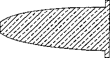
图27是具有整体光杆的护套灯泡的剖视图。Figure 27 is a cross-sectional view of a jacketed bulb with an integral polished rod.
图28是具有整体光杆的护套灯泡的剖视图,其中球形护套切成斜角。Figure 28 is a cross-sectional view of a jacketed bulb with an integral polished rod, with the spherical jacket cut at a bevel.
图29是具有整体透镜的无电极灯泡的剖视图。Figure 29 is a cross-sectional view of an electrodeless light bulb with an integral lens.
图30是采用图29灯泡的开孔式灯的剖视图。Fig. 30 is a cross-sectional view of an apertured lamp using the bulb of Fig. 29 .
图31是球形透镜的示意图。Fig. 31 is a schematic diagram of a spherical lens.
图32是根据本发明第一方面的模制球形透镜的示意图。Figure 32 is a schematic illustration of a molded spherical lens according to the first aspect of the invention.
图33是模制球形透镜的前侧示意图。Figure 33 is a schematic front view of a molded spherical lens.
图34是制造模制球形透镜的模具的剖视图。Fig. 34 is a sectional view of a mold for manufacturing a molded spherical lens.
图35是制造模制球形透镜的另一模具的剖视图。Fig. 35 is a cross-sectional view of another mold for manufacturing a molded spherical lens.
图36是具有整体凸缘的模制CPC的示意图。Figure 36 is a schematic illustration of a molded CPC with an integral flange.
图37是模制CPC的剖视图。Figure 37 is a cross-sectional view of a molded CPC.
图38是具有整体凸缘的模制TLP的立体图。Figure 38 is a perspective view of a molded TLP with an integral flange.
图39是模制TLP的剖视图。Figure 39 is a cross-sectional view of a molded TLP.
图40是具有斜角台阶的锥形光圆锥体的示意图。Figure 40 is a schematic illustration of a tapered light cone with angled steps.
图41是与透镜一起的锥形光圆锥体的示意图。Figure 41 is a schematic diagram of a tapered light cone with a lens.
图42-44分别是CPC的示意性的左视图、前视图和仰视图。42-44 are schematic left, front and bottom views, respectively, of a CPC.
图45-47分别是沿图42-44的虚线截取的截头CPC的示意性俯视图、前视图和右视图。45-47 are schematic top, front and right side views, respectively, of a truncated CPC taken along the dashed lines of FIGS. 42-44.
图48是配有远程开孔的截头CPC的前视图。Figure 48 is a front view of a truncated CPC equipped with a remote port.
图49是一被分割的实心CPC的立体图。Figure 49 is a perspective view of a segmented solid CPC.
图50是一被分割的空心CPC的立体图。Figure 50 is a perspective view of a segmented hollow CPC.
图51是根据本发明一个方面的弯曲边缘射线光系统的示意图。51 is a schematic diagram of a curved edge-ray optics system according to one aspect of the invention.
图52是弯曲边缘射线的另一光系统的示意图。Figure 52 is a schematic diagram of another optical system that bends edge rays.
图53是根据本发明的一个方面采用etendue选择方法的灯系统的剖开示意图。Figure 53 is a schematic cut-away diagram of a lamp system employing etendue selection methods in accordance with one aspect of the present invention.
图54是根据本发明的一个方面采用角度选择方法和积分器的灯系统的剖视图。54 is a cross-sectional view of a lamp system employing an angle selection method and an integrator according to one aspect of the present invention.
图55-59分别是图54所示的灯系统的另外光学结构的剖开示意图。55-59 are schematic cross-sectional views of other optical structures of the lamp system shown in FIG. 54, respectively.
图60是图59中区域60的放大的视图。FIG. 60 is an enlarged view of
图61是根据本发明的一个方面的光系统一例子的示意图。Figure 61 is a schematic diagram of an example of a light system according to an aspect of the present invention.
图62是根据本发明的一个方面的光系统另一例子的示意图。Fig. 62 is a schematic diagram of another example of an optical system according to an aspect of the present invention.
图63是根据本发明的一个方面的光系统的又一例子的示意图。63 is a schematic diagram of yet another example of a light system according to an aspect of the present invention.
图64是根据本发明的一个方面的投影系统的示意图。Figure 64 is a schematic diagram of a projection system according to an aspect of the present invention.
图65是根据本发明另一方面的采用偏光器立方体的灯系统的示意图。65 is a schematic diagram of a lamp system employing a polarizer cube according to another aspect of the invention.
图66是根据本发明另一方面的采用偏光器立方体的灯系统的示意图。66 is a schematic diagram of a lamp system employing a polarizer cube according to another aspect of the invention.
图67-69分别是根据本发明一个方面的一光学保持件的示意性俯视图、左视图和右视图。67-69 are schematic top, left and right side views, respectively, of an optical holder according to an aspect of the present invention.
图70是适用于光学保持件的一开孔式灯泡的前示意图。Figure 70 is a front schematic view of an apertured light bulb suitable for use with an optical holder.
图71-72分别是根据本发明一个方面的透镜管的示意性左视图和俯视图。71-72 are schematic left and top views, respectively, of a lens tube according to an aspect of the present invention.
图73是适用于容纳在透镜管中的RF屏幕的示意图。Figure 73 is a schematic illustration of an RF screen suitable for housing in a lens tube.
图74是安装在管子中的RF屏幕的放大的局部剖视图。Figure 74 is an enlarged partial cross-sectional view of an RF screen installed in a tube.
图75是用于本发明一个方面的光盒的壳体的立体图。Figure 75 is a perspective view of a housing for a light box of an aspect of the present invention.
图76是用在光盒中的透镜的立体图。Figure 76 is a perspective view of a lens used in a light box.
图77是光盒的局部剖视图。Fig. 77 is a partial sectional view of the light box.
本发明的详细说明Detailed Description of the Invention
在以下的叙述中,为了说明而不是限定,引用具体的细节,诸如特定的结构、界面、工艺等等,以便全面理解本发明。然而本领域的技术人员应知道,所公开的内容的利益可使本发明应用在脱离这些具体细节的其它实施例。在某些情况下,省略对众所周知的装置和方法的说明,使本发明的说明显得清楚。In the following description, for purposes of illustration rather than limitation, specific details are cited, such as specific structures, interfaces, processes, etc., in order to provide a comprehensive understanding of the present invention. It will be appreciated, however, by those skilled in the art that the benefit of this disclosure may allow the invention to be employed in other embodiments that depart from these specific details. In certain instances, descriptions of well-known devices and methods are omitted so as not to obscure the description of the present invention.
Etendue再循环Etendue recycling
根据本发明,光的增加量从开孔式灯传输到所需的etendue,例如上文引用的PCT公开号WO99/36940描述了开孔式灯。在某些应用中,例如投影系统,一个重要的性能参数是传输到例如具有给定区域和角接收度的光学成像元件的光通量,在本文中,etendueε定义为:According to the present invention, an increased amount of light is delivered to the desired etendue from an apertured lamp, such as that described in PCT Publication No. WO99/36940 cited above. In some applications, such as projection systems, an important performance parameter is the luminous flux delivered to, for example, an optical imaging element with a given area and angular acceptance, in this paper etendueε is defined as:
ε=π×(面积)×sin2(θ)ε=π×(area)×sin 2 (θ)
式中,θ表示特定光线的锥形体的半角。where θ represents the half-angle of the cone for a particular ray.
一三维光源,诸如传统的弧光灯,采用一外反射体,以将光改道和聚焦在所需的物体或平面上,由于收集效率及其它因素,因而伴随着损耗。此外,一弧光灯一般仅提供局部的明亮点,光源的大部分光通量从不同的几乎很少光亮的放电部分散发。A three-dimensional light source, such as a conventional arc lamp, employs an external reflector to redirect and focus the light on the desired object or plane, with attendant losses due to collection efficiency and other factors. Furthermore, an arc lamp generally provides only localized bright spots, with most of the luminous flux of the source being emitted from various, barely bright discharge portions.
‘940公开文本中的开孔式灯旨在通过提供一光输出非常均匀的两维光源来解决上面的大部分问题。一球形透镜放置成与灯开孔接触,此后,采用合适的透镜提供具有所需射束角度的光。但是,本发明证实了进一步改进的潜力。The aperture lamp of the '940 publication aims to solve most of the above problems by providing a two-dimensional light source with a very uniform light output. A spherical lens is placed in contact with the lamp opening, after which suitable lenses are used to provide light with the desired beam angle. However, the present invention demonstrates the potential for further improvements.
图2示出了来自开孔式灯的实际光分布。如图2所示,对于较大的角度,光输出的衰退较Lambertian(朗伯)cos(θ)曲线快。Lambertian光学分布具有恒定的亮度。换句话将,从任何角度看到的亮度是相同的。其结果是,Lambertian光源的任何角虑光产生同样的亮度。光以与etendue相同的速度增加或减少。Figure 2 shows the actual light distribution from an apertured lamp. As shown in Figure 2, for larger angles, the light output decays faster than the Lambertian cos(θ) curve. A Lambertian optical distribution has constant brightness. In other words, the brightness seen from any angle will be the same. As a result, any corner of the Lambertian source produces the same brightness. Light increases or decreases at the same rate as etendue.
但是,对于次Lambertian光源,在大角度的光比较少。在‘940公开文本中揭示的透镜结构将这些角度引入到传输光中,并因此增加etendue成比例地大于它们增加的光。根据本发明的一个方面,一所需角度之外的光被反射回到灯中,以减少次Lambertian光输出对etendue的影响。根据本发明的另一方面,灯开孔的尺寸增加到受抑制的输出角度,较大的灯开孔面积与目标etendue匹配。当输出光的量有明显增加时,增加开孔尺寸具有略微降低正向峰值定向亮度(peak forward directed brightness)的作用,这种差别表示指向目标etendue的光的量有所增加。However, for sub-Lambertian light sources, there is less light at large angles. The lens structures disclosed in the '940 publication introduce these angles into the transmitted light, and thus increase etendue proportionally greater than the light they increase. According to one aspect of the invention, light outside a desired angle is reflected back into the lamp to reduce the effect of sub-Lambertian light output on etendue. According to another aspect of the invention, the size of the lamp aperture is increased to suppress output angles, the larger lamp aperture area matches the target etendue. While there is a significant increase in the amount of output light, increasing the aperture size has the effect of slightly reducing the peak forward directed brightness, a difference that indicates an increase in the amount of light directed at the target etendue.
一个能够etendue再循环的灯系统采用一球形透镜,该球形透镜具有一构成开孔的可反射外表面。大角度光被反射返回灯中,其中光通过先前的积分球形(integrating sphere)途径,以给定的概率被再吸收和再射出。这导致光的输出降低,但也降低了etendue。通过增加灯开孔的尺寸可进一步增加光的输出。A lamp system capable of etendue recycling employs a spherical lens having a reflective outer surface forming an aperture. Light at large angles is reflected back into the lamp, where it passes through the previous integrating sphere, is reabsorbed and re-emitted with a given probability. This results in lower light output, but also lower etendue. The light output can be further increased by increasing the size of the lamp opening.
图1是进行etendue再循环的一较较佳灯系统的示意性剖视图。一开孔式灯3包括一设置在陶瓷罩7内的灯泡5。灯泡5对着一前陶瓷垫圈9定位,该陶瓷垫圈9构成一第一开孔11。罩7内没有被灯泡5占据的空间填充可反射陶瓷材料13。一后陶瓷盘15在反射材料13后面位于罩7内。有关开孔式灯3的构造的进一步细节可参考’940公开文本。Figure 1 is a schematic cross-sectional view of a preferred lamp system for etendue recycling. An
球形透镜17位于开孔11的前面,用于减小从开孔11射出的光的射束角度。光学元件19与球形透镜17隔开,并构成一对应于要通过光所需角度的第二开孔21,其中该角度相对于光学对称轴构成。面对开孔11的光学元件的反射表面23被构成至少使在所需角度之外的部分光回进灯泡5,其间可通过等离子体被吸收和再射出。例如,沿路径A传播的光子沿路径B离开球形透镜17,其间光子遇到光学元件19并沿路径C返回到灯泡5。有一非零概率,返回的多余光的一部分将再射出并在所需角度内离开第一开孔11经过第二开孔21,由此增加通过开孔21的光的强度。The
在图1所示的较佳实施例中,球形透镜17有一第一半径R1,光学元件19有一较R1大的第二半径R2。球形透镜17和光学元件19不享有同一中心。但是,它们各自的中心点C1、C2沿中心线CL表示的公共光学轴线对齐。光学元件19构造成其中心点C2位于灯泡5的内部,最好靠近开孔11,使得光学元件19反射的大部分光经开孔11传输到灯泡5中。In the preferred embodiment shown in FIG. 1, the
图3表示灯系统采用无制约输出、具有制约输出而无再循环以及采用etendue再循环的具有制约输出的光强度对射束角度的曲线图。从曲线图中可清楚地看出,简单地对输出制约(例如用一非反射开孔止挡件)不会增加强度,只是缩小光的射束角度。但是,根据本发明采用etendue再循环(例如用图1的实施例),不仅仅是射束角度缩小,光强度也有显著增加。Figure 3 shows a graph of light intensity versus beam angle for a lamp system with unrestricted output, with reconditioned output without recirculation, and with recirculated etendue with recirculated output. From the graph it is clear that simply limiting the output (for example with a non-reflective aperture stop) does not increase the intensity, only narrows the beam angle of the light. However, with etendue recirculation according to the invention (for example with the embodiment of FIG. 1 ), not only is the beam angle reduced, but the light intensity is also significantly increased.
高温偏光再循环High temperature polarized light recycling
如前述’091专利所指出的,非所需极性的光可通过诸如硫磺、硒、碲、卤化铟和其它卤化金属的某些灯等离子体有利地再循环。传统的用于进行这些再循环的光学元件包括诸如由3M公司制造的双面亮度增强膜(DBEF)的光学膜。这些膜一般由塑料制成,不能承受高温。此外,这些膜在紫外线下会退化,由此限制了采用这些膜的光学系统在宽光谱光下的使用寿命。As noted in the aforementioned '091 patent, light of an undesired polarity can be advantageously recycled by certain lamp plasmas such as sulfur, selenium, tellurium, indium halides, and other metal halides. Conventional optical elements used for these recyclings include optical films such as Double Sided Brightness Enhancement Film (DBEF) manufactured by 3M Company. These membranes are generally made of plastic and cannot withstand high temperatures. In addition, these films degrade under UV light, thereby limiting the lifetime of optical systems employing these films under broad-spectrum light.
图4是本发明的采用高温线栅偏光器以使偏振光再循环的灯系统的示意性剖视图。开孔式灯33类似于开孔式灯3,它包括一设置在陶瓷罩37内的灯泡35。灯泡35对着一构成开孔41的前陶瓷垫圈39定位。罩37内没有被灯泡35占据的空间填充可反射陶瓷材料43。一后陶瓷盘45在反射材料43后面位于罩37内。4 is a schematic cross-sectional view of a lamp system of the present invention employing a high temperature wire grid polarizer to recycle polarized light. The aperture lamp 33 is similar to the
根据本发明的一个方面,一线栅偏光器46直接位于开孔41的前面。一球形透镜47对着偏光器46定位在偏光器46的相对于开孔41的相对侧。灯系统还可包括一可选择的清除偏光器49,在图4中该偏光器49设置在球形透镜47的曲线外表面。According to one aspect of the invention, a wire grid polarizer 46 is located directly in front of the aperture 41 . A spherical lens 47 is positioned opposite the polarizer 46 on the opposite side of the polarizer 46 to the aperture 41 . The lamp system may also include an optional clear polarizer 49 disposed on the curved outer surface of the spherical lens 47 in FIG. 4 .
线栅偏光器46构造成使所需极性的光通过、使非所需极性的光经开孔41反射回到灯泡35中。返回的光具有被填充物吸收的非零概率,并再射出所需极性,由此增加有用的光输出。线栅偏光器46的一个优点是它是由高温材料(例如金属和玻璃)制成,能够承受高的工作温度(例如至少约400℃)。合适的线栅偏光器可从市场上买到,例如包括犹他州的奥勒姆的Moxtek公司。Wire grid polarizer 46 is configured to pass light of a desired polarity and reflect light of an undesired polarity back into bulb 35 through aperture 41 . The returning light has a non-zero probability of being absorbed by the fill and re-emitted of the desired polarity, thereby increasing the useful light output. One advantage of the wire grid polarizer 46 is that it is made of high temperature materials (eg, metal and glass) and can withstand high operating temperatures (eg, at least about 400°C). Suitable wire grid polarizers are commercially available including, for example, Moxtek of Orem, Utah.
根据特定的灯结构,直接在开孔41前面的温度仍然可能超过偏光器46的最大工作温度。在这种情况下,偏光器46可省略,用清除偏光器49取代,作为灯系统的主偏光器。偏光器46和49可与球形透镜47一体制成或制成单独件。Depending on the particular lamp construction, the temperature directly in front of the opening 41 may still exceed the maximum operating temperature of the polarizer 46 . In this case, the polarizer 46 can be omitted and replaced by a clear polarizer 49 as the main polarizer of the lamp system. Polarizers 46 and 49 can be made integral with ball lens 47 or as a separate piece.
Etendue和偏光再循环Etendue and polarized light recycling
图5是本发明采用etendue再循环和偏光再循环的灯系统的剖开示意图。一开孔式灯3和图1中所述的相同。球形透镜17位于开孔式灯3的前面,光学元件19与开孔式灯3分开。线栅偏光器51设置在由光学元件19构成的第二开孔21中。Fig. 5 is a cut-away schematic diagram of a lamp system using etendue recirculation and polarized light recirculation according to the present invention. An
工作时,在由开孔21构成的所需角度之外的至少一部分光经开孔11反射回到灯泡5,在所需角度之内的但没有所需极性的至少一部分光也经开孔11反射到灯泡5。因此,经开孔21离开灯系统的光既在所需角度之内,又具有所需极性。回到灯泡的光的一部分通过等离子体再循环,并在所需角度之内离开灯系统,又具有所需极性,由此增加了有用光的输出。In operation, at least a portion of the light outside the desired angle formed by the
有利的是,偏光器51与开孔式灯3充分分开,以将偏光器的工作温度保持在一合适的工作温度,一般大大小于其规定最大工作温度。此外,线栅偏光器51的材料在紫外光线下不会明显地退化,由此不会限制灯系统的使用寿命。Advantageously, the polarizer 51 is sufficiently separated from the
组合的etendue/偏光再循环灯系统的再一个优点是与线栅偏光器51一起的构造合适的光学元件19能够减少电磁界面(EMI)渗漏。光学元件19和偏光器51可由导电材料制成。例如,光学元件19可由银制成的镜子组成,线栅偏光器51可由金属丝阵列组成。根据本发明的一个方面,光学元件19和偏光器51合并到也由导电材料(例如铝)制成的透镜管中,所有这些经电气连接在一起并接地以形成有效的EMI防护屏。Yet another advantage of the combined etendue/polarized light recirculating lamp system is that properly constructed
光和光纤有效结合Effective Combination of Light and Optical Fiber
根据本发明的一个方面,灯系统构造成将开孔式灯的光更有效地偶合到光纤束中,其中光纤束有在各单独纤维之间的空隙空间。这样的空隙空间可能由例如包围各纤维的金属包覆层引起的“死角空间”。在传统的灯系统中,来自灯的穿过空隙空间的光随后不会在纤维中传送,作为废弃光损失掉了。这种空隙空间占纤维束的15-40%,并因此表明光的损失很大。According to one aspect of the present invention, a lamp system is configured to more efficiently couple light from an aperture lamp into a fiber optic bundle having interstitial spaces between individual fibers. Such void spaces may be "dead spaces" caused by, for example, the metal cladding surrounding the individual fibers. In conventional lamp systems, light from the lamp that passes through the void space is not then transmitted in the fiber and is lost as waste light. This void space accounts for 15-40% of the fiber bundle and thus represents a significant loss of light.
根据本发明,该问题是通过在光纤束的接收表面的空隙区域上沉积一反射层来克服的,同时保持各个纤维表面不相接触。然后从空隙区域中反射的光被送回到有效灯容积中,其一部分再循环和再射出。再射出光具有贯穿和进入有效纤维表面的非零概率,如同由纤维传导的光。反射空隙空间有效地成为开孔式灯的反射外壳的一部分。类似地,然后各个纤维开孔的总和表示灯的有效开孔区域,在构造开孔式灯时最好将这种有效开孔区域考虑在内。According to the invention, this problem is overcome by depositing a reflective layer on the interstitial area of the receiving surface of the fiber bundle, while keeping the individual fiber surfaces out of contact. The light reflected from the void area is then sent back into the active lamp volume, a portion of which is recycled and re-ejected. Re-exited light has a non-zero probability of penetrating and entering the active fiber surface, as does light conducted by the fiber. The reflective void space effectively becomes part of the reflective envelope of the apertured lamp. Similarly, the sum of the individual fiber apertures then represents the effective aperture area of the lamp, which is preferably taken into account when constructing apertured lamps.
图6是本发明第一光纤束的局部立体图。光纤束61包括多个单个光纤63。各光纤63在它们之间构成空隙空间,反射材料65设置在空隙空间之上。Fig. 6 is a partial perspective view of the first optical fiber bundle of the present invention.
图7是一根据本发明利用光纤束的灯系统的示意性局部剖视图。开孔式灯62包括一被反射陶瓷制品66覆盖的灯泡64,该陶瓷制品构成一开孔67。灯系统构造成光纤束61的一端设置有反射材料65,该端设置在开孔67附近。从等离子体68射出的光子离开开孔沿路径A进入单个纤维63并通过光纤传输。从等离子体68射出的光子离开开孔沿路径B遇到反射材料65并返回到等离子体68,并在那儿被等离子体68吸收后再射出,以非零概率进入各个光纤63之一。Figure 7 is a schematic partial cross-sectional view of a lamp system utilizing fiber optic bundles in accordance with the present invention. The
有利的是,光纤束的光学性有助于适于将反射层沉积在空隙空间上的多种处理方法。一种这样的方法将在下面描述。Advantageously, the optics of the fiber bundle facilitate a variety of processing methods suitable for depositing the reflective layer on the void space. One such method is described below.
光敏表面化学在图案(样式)金属化领域中是众所周知的。在这类方法中,在对象表面上沉积一薄膜光敏层。然后将薄膜曝光于具有样式图像的光中,该光能够改变在曝光于此光的区域中的光敏层的化学活性。然后用其它化学制品对曝光表面显影,以去掉那些曝光区域中的最初的光敏层,有选择地在那些没有曝光的区域中沉积薄膜金属反射层。对覆盖有效纤维表面的区域进行曝光就象将纤维束的其它表面曝光于必需光中以使薄膜光敏化一样简单。Photosensitive surface chemistry is well known in the art of pattern (pattern) metallization. In such methods, a thin-film photosensitive layer is deposited on the surface of the object. The film is then exposed to a patterned image of light capable of altering the chemical activity of the photosensitive layer in the areas exposed to this light. The exposed surface is then developed with other chemicals to remove the original photosensitive layer in those exposed areas and selectively deposit a thin-film metallic reflective layer in those areas that were not exposed. Exposing the area covering the active fiber surface is as simple as exposing the other surfaces of the fiber bundle to the light necessary to photosensitize the film.
图8A至8D是根据本发明制造光纤束的方法步骤的示意性剖视图。图8A示出了一最初的光纤束71,它包括多个单个纤维73和空隙材料74。在图8B中,一光敏粘结层77沉积在光纤束71的一端,光纤束71的另一端曝光于合适光79中,以活化粘结层77。实际上只有与各个纤维73叠合的层77的区域曝光于光中。如图8C所示,在进一步处理之后,留下的粘结层77对应于与空隙区域74叠合的区域。最终,如图8D所示,一金属化反射层75有选择地沉积在留下的粘结层77上。8A to 8D are schematic cross-sectional views of steps in a method of manufacturing an optical fiber bundle according to the present invention. FIG. 8A shows an initial
有大量的其它方法能够用于有选择地将光纤束中空隙区域转换成反射表面。如上方法是用添加法,即反射材料有选择地添加到空隙空间中。有选择地消减法也可应用,即将最初的薄膜光敏粘结层留在纤维端表面,并从空间区域中去掉,随后使整个表面涂覆上反射材料,该反射材料能够良好地粘结到未涂覆光敏层的空隙区域上;然后将最终的表面暴露于腐蚀剂,该腐蚀剂腐蚀在有效纤维端面上的在下面显影的光敏材料,但该腐蚀剂不腐蚀在空隙材料上的反射涂层。这种选择可以实现,例如,一有机光敏材料和一无机反射层(可以是金属的或二向色的(dichroic))。There are a number of other methods that can be used to selectively convert void regions in fiber bundles into reflective surfaces. The above method is an additive method, that is, the reflective material is selectively added to the void space. A selective subtractive method can also be used, that is, the initial film photosensitive adhesive layer is left on the fiber end surface and removed from the space area, and then the entire surface is coated with a reflective material, which can be well bonded to the future. coating the photosensitive layer over the voided areas; the resulting surface is then exposed to an etchant which attacks the underlying developed photosensitive material on the active fiber end face, but which does not attack the reflective coating on the voided material. This selection can be achieved, for example, with an organic photosensitive material and an inorganic reflective layer (which can be metallic or dichroic).
图9A至9D是制造本发明光纤束的另一方法步骤的示意性剖视图。在图9A中,光纤束81有一层有机材料87,该有机材料87光稳定地沉积在光纤束一端表面。光纤束81的另一端曝光于合适光89中,以稳定材料87。如图9B所示,进一步处理之后,留下的材料87是与纤维83叠合的材料,而去掉的材料是与空隙材料84叠合的材料。在图9C中,有方向性地沉积的反射层85被加到光纤束81上。在图9D中,用一溶剂有选择地去掉有机层87和沉积在其上的反射材料85。留下的反射层85相等于与空隙材料84叠合的反射材料。9A to 9D are schematic cross-sectional views of further method steps for manufacturing the optical fiber bundle of the present invention. In FIG. 9A, the
有利的是,上述两个方法采用纤维束的几何形状来为反射层有选择的加工提供自动对齐的方便,由此省略了附加遮光膜并简化了制造工艺。Advantageously, the above two methods use the geometry of the fiber bundle to provide self-alignment facilities for the selective processing of the reflective layer, thereby eliminating the need for additional light-shielding films and simplifying the manufacturing process.
色彩再循环(color recycling)Color recycling
图10是本发明的第二种光纤束的示意性剖视图。根据本发明的一个方面,空隙空间中的反射材料结合有选择性的波长反射,可以再循环更多的光。在图10中,光纤束91包括单独的光纤93和空隙材料94。光纤束91的一端还包括一与空隙材料94叠合的全反射层95,以及一层在图10中显示的有选择性的反射层97,它覆盖光纤束91那一端的整个表面,但该反射层至少要和纤维93叠合。例如,有选择地反射的材料97可包括红/绿/蓝分色波段通过材料。在工作中,到达反射层95的光反射回到灯泡,在所需波长之外并到达反射层97的光有选择地反射回到灯泡以再循环。根据处理工艺考虑,有选择反射层97和反射层95的次序可反过来(例如,二向色材料可在金属材料的顶部)。Fig. 10 is a schematic cross-sectional view of a second optical fiber bundle of the present invention. According to one aspect of the invention, the reflective material in the void space, combined with selective wavelength reflection, can recycle more light. In FIG. 10 , an
或者,用三个分离的光纤束有选择地吸取同时从同一盏灯的三个开孔中分离出来的波段(每一个分别对应于红、绿和蓝),而没有被使用的光从每一开孔中再循环。三个分离的纤维或纤维束可为三个所需的波段涂覆有分色波段通过滤光器。从每一波段通过滤光器反射的光立即再循环,这是因为滤光器接近开孔式灯。Alternatively, use three separate optical fiber bundles to selectively absorb the wavelength bands simultaneously separated from the three openings of the same lamp (one for red, green and blue respectively), while the unused light comes from each Recirculation in the opening. Three separate fibers or fiber bundles can be coated with dichroic bandpass filters for the three desired wavelength bands. Light reflected from each band through the filter is immediately recycled due to the proximity of the filter to the apertured lamp.
在另一不同的形式中,一大芯光纤、一呈锥形的光管(TLP)或其它光导管可在开孔式灯的远端导管的末端处构造有分色波段通过滤光器。在所需波长之外的光被反射经过纤维/锥光管/光导管并通过开孔再进入灯。如上所述,三个分离的导管可用于红绿蓝波段中的每一个。纤维/锥光管/光导管还可在任一端部装有极化(偏振)滤光器,以再循环非所需极性的光。In a different form, a large core fiber, a tapered light pipe (TLP) or other light guide can be constructed with a dichroic bandpass filter at the end of the distal guide tube of the aperture lamp. Light outside the desired wavelength is reflected through the fiber/cone/light pipe and through the aperture to enter the lamp. As mentioned above, three separate conduits are available for each of the red, green and blue bands. The fiber/cone/light guide can also be fitted with a polarizing (polarizing) filter at either end to recycle light of an undesired polarity.
图11是本发明的第三种光纤束的立体图。单一的纤维束101在不同的几何区域中构造成具有各自的波段通过滤光器R、G和B,从而为红绿蓝三色中的每一色分离成各自的输出窗口103、105和107。从各波段通过滤光器反射的光由于过滤器接近开孔式灯而立即再循环。在远程窗口103、105和107可应用一偏振滤光器,由此通过反射不需要的极性的光经纤维返回以再循环而进一步提高灯的生成效率。纤维束101在其R/G/B波段通过滤光器端部的空隙空间中还可包括反射材料。Fig. 11 is a perspective view of a third optical fiber bundle of the present invention. A single fiber bundle 101 is configured with respective bandpass filters R, G and B in different geometric regions, thereby separating into respective output windows 103, 105 and 107 for each of the three colors red, green and blue. Light reflected by the filter from each wavelength band is immediately recirculated due to the proximity of the filter to the apertured lamp. A polarizing filter may be applied at the remote windows 103, 105 and 107, thereby further increasing lamp generation efficiency by reflecting light of unwanted polarity back through the fiber for recycling. Fiber bundle 101 may also include reflective material in the void space at the end of its R/G/B band pass filter.
显微透镜阵列microlens array
图12根据本发明采用一显微透镜阵列的灯系统的示意性局部剖视图。显微透镜阵列111包括三个透镜113、115和117。每一透镜113、115和117的一侧面被处理成全反射色光的分光镜,它为该透镜限定为“局部开孔”,此外各透镜还设置一波长选择性波段通过滤光器(如三色中的一种),它限定了哪一颜色可通过该透镜。阵列111靠近灯泡121设置,并位于由灯泡121周围的反射陶瓷125构成的开孔123中。三个透镜在不同的光学轴线,导致三个独立的图像,一个图像对应于一种色彩波段。每一色彩的废弃光再循环进入灯的等离子体。Figure 12 is a schematic partial cross-sectional view of a lamp system employing a microlens array according to the present invention. The microlens array 111 includes three lenses 113 , 115 and 117 . One side of each lens 113, 115 and 117 is processed into a beam splitter of total reflection color light, which is defined as "partial opening" for this lens, and each lens is also provided with a wavelength-selective waveband pass filter (such as three colors) in addition. one of) that defines which colors can pass through the lens. The array 111 is positioned adjacent to the bulb 121 in an aperture 123 formed by reflective ceramic 125 surrounding the bulb 121 . The three lenses are on different optical axes, resulting in three separate images, one image corresponding to one color band. Wasted light of each color is recycled into the plasma of the lamp.
作为举例说明给出了前面的光学系统,这不能作为限定。作为本说明书的好处,许多其它光学系统可以采用本发明的各个方面。The preceding optical system is given by way of illustration, not limitation. With the benefit of this description, many other optical systems may employ aspects of the invention.
过充满CPC的倒角开孔Chamfered openings filled with CPC
根据本发明的一个方面,一开孔式灯具有一锥形开孔,以使距过充满光学零件的较近的光学通路。According to one aspect of the invention, an apertured luminaire has a tapered aperture to allow closer optical access to the overfill optics.
当光学元件的入口表面(即最接近开孔式灯的表面)没有完全被光源照亮时,光学元件被说成是未充满。如果入口表面大于开孔,光学元件与开孔靠得很近,那么这种现象就可能出现。例如,在图5中的球透镜17相对于开孔11未充满。另一方面,当入口表面完全被光源照亮,则光学元件被说成是过充满。当入口表面小于开孔或光学元件与开孔分开时这种现象就会出现。例如,图7中光纤束61相对于开孔67为过充满。An optical element is said to be underfilled when the entrance surface of the optical element (ie, the surface closest to the aperture lamp) is not fully illuminated by the light source. This phenomenon can occur if the entrance surface is larger than the aperture and the optics are in close proximity to the aperture. For example, the
某些未充满光学元件的一个问题是具有视差黑圈的外观,这在光输出中引起不希望的不均匀。而过充满光学元件的一个问题是在光学元件边缘之外的光损失。One problem with certain underfilled optics is the appearance of parallax black circles, which cause undesirable non-uniformity in light output. One problem with overfilling an optical element is light loss beyond the edge of the optical element.
本发明在这个方面通过使开孔表面成斜角使光学元件较近地定位,从而减少过充满光学元件丧失光的量。The present invention in this aspect reduces the amount of light lost by overfilling the optical element by beveling the aperture surface to position the optical element closer together.
参阅图13-14,一灯系统131包括一灯泡133,该灯泡除光发射开孔137区域之外都被包装在反射陶瓷制品135之中。一陶瓷盘136(可以是与开孔式灯一体的)构成一开孔137。盘136的一表面138呈斜锥形,从而使盘136接触灯泡133的侧面上的孔的面积小于盘136的相对侧面上孔的面积。换句话将,开孔133的面积在沿光学轴线方向随着远离灯泡133而增加。这种结构使得到灯泡133的光学通路较大,光学元件就可与面积均匀的开孔相比设置得更接近灯泡。Referring to Figures 13-14, a lamp system 131 includes a bulb 133 encased in a reflective ceramic 135 except in the area of the light emitting opening 137. A ceramic disc 136 (which may be integral to the apertured lamp) defines an aperture 137 . One surface 138 of disc 136 is obliquely tapered so that the area of the hole on the side of disc 136 contacting bulb 133 is smaller than the area of the hole on the opposite side of disc 136 . In other words, the area of the opening 133 increases along the optical axis as the distance from the bulb 133 increases. This configuration allows for a larger optical path to the bulb 133, allowing the optical elements to be placed closer to the bulb than would be possible with a uniform area opening.
具有构成灯开孔的反射入口表面的空心CPCHollow CPC with reflective entrance surface forming lamp opening
根据本发明的一个方面,一第一光学元件形成开孔式灯的整体容积的一部分并构成光的发射开孔。According to one aspect of the invention, a first optical element forms part of the overall volume of the apertured lamp and constitutes the light emission aperture.
如上所述,开孔式灯具有有关过充满或未充满光学元件的问题。本发明通过采用在其表面具有反射涂层的空心光学元件来克服这些问题。As mentioned above, apertured lamps have problems with overfilling or underfilling the optics. The present invention overcomes these problems by using a hollow optical element with a reflective coating on its surface.
参阅图15,一灯系统141包括一灯泡和一陶瓷盘143,该盘构有一开孔145。一空心光学元件147有一相对于盘143定位的表面149并构成一开孔151,根据本发明的该方面,表面149的外周边在开孔145的周边外面,而表面149的内周边在开孔145的周边的里面,表面149适合于在至少可视区域内具有高反射性(例如大于90%)。一部分光撞击表面149的反射表面后返回到射出光的等离子体(plasma)。因此,表面149形成开孔式灯泡的整体容积的一部分,开孔151为开孔式灯泡提供光发射开孔。Referring to FIG. 15 , a lamp system 141 includes a bulb and a ceramic disc 143 defining an opening 145 . A hollow optical element 147 has a surface 149 positioned relative to the disk 143 and defining an opening 151. According to this aspect of the invention, the outer periphery of the surface 149 is outside the periphery of the opening 145 and the inner periphery of the surface 149 is outside the periphery of the opening 145. Inside the perimeter of 145, surface 149 is adapted to be highly reflective (eg greater than 90%) in at least the viewable area. A portion of the light hits the reflective surface of surface 149 and returns to the plasma from which the light was emitted. Thus, surface 149 forms part of the overall volume of the apertured bulb and aperture 151 provides a light emission opening for the apertured bulb.
有利的是,本发明通过光学元件147因在其光输出中具有良好的空间和角度的均匀性而能保持高亮度。一空心的光学元件潜在地比光的etendue转换方面更为有效。例如,如上所述,一实心光学元件必需不充满开孔(即过充满光)。与实心光学元件相比,尤其是与覆盖开孔145和在灯泡与光学元件之间形成一封闭的绝缘空间的实心光学元件相比,空心光学元件还为灯泡窗口的传导冷却提供较好的热力特性。本发明在这方面的另一优点是在开孔式灯泡与第一光学元件之间的不严格的公差。由于光学元件自身构成了灯泡开孔,系统是自动对齐的,光学元件不需要相对灯泡精确对中。Advantageously, the present invention maintains high brightness through optical element 147 due to good spatial and angular uniformity in its light output. A hollow optical element is potentially more efficient in terms of etendue conversion of light. For example, as noted above, a solid optical element must not fill the aperture (ie, overfill it with light). Hollow optics also provide better thermal conduction cooling of the bulb window than solid optics, especially compared to solid optics that cover opening 145 and form a closed insulating space between the bulb and optics. characteristic. Another advantage of the invention in this respect is the loose tolerance between the apertured bulb and the first optical element. Since the optic itself forms the bulb opening, the system is self-aligning and the optic does not need to be precisely centered relative to the bulb.
例如,光学元件147的表面149和内侧表面153涂覆有一高温分色涂层,以提供合适的反射表面。根据涂覆工艺,可以任意选择对整个光学元件147加以涂覆,可能在成本上更为有效。尽管光学元件147被说明为CPC,其它空心光学元件也可采用,包括TLP(锥形光管)、光杆或积分器(intrgrator)和球形反射器或角度选择器,并无限制。For example, surface 149 and interior surface 153 of optical element 147 are coated with a high temperature dichroic coating to provide a suitable reflective surface. Depending on the coating process, coating the entire optical element 147 may optionally be more cost effective. Although optical element 147 is illustrated as a CPC, other hollow optical elements may be used including, without limitation, TLPs (tapered light pipes), optical rods or integrators (intrgrators), and spherical reflectors or angle selectors.
最好是,空心光学元件147没有接缝,或在内侧表面153的接缝尽可能少。制造没有内接缝的光学元件的一个方法是绕一无缝的模子收缩一空心石英管。Preferably, the hollow optical element 147 has no seams, or as few seams as possible on the inside surface 153 . One method of making optics without inner seams is to shrink a hollow quartz tube around a seamless mold.
有选择的高角度截止Selective High Angle Cutoff
根据本发明的一个方面,高角度光可从光束中去掉并返回到等离子体,其中返回光的一部分在所需射束角度内再射出。在这方面,角度的选择尽可能靠近射出光的等离子体。所选角度的范围例如可相当于光学元件的接收角。除提高光源的效率外,本发明还提高了从开孔射出的光的利用效率,因为射出光在射束角度上较均匀。According to one aspect of the invention, high angle light can be removed from the beam and returned to the plasma, with a portion of the returned light re-emitted within the desired beam angle. In this respect, the angle is chosen as close as possible to the plasma from which the light emerges. The selected range of angles may correspond, for example, to the acceptance angle of the optical element. In addition to improving the efficiency of the light source, the invention also improves the utilization efficiency of the light emitted from the opening, because the emitted light is relatively uniform in beam angle.
参阅图16,灯系统154包括一灯泡155,除开孔159区域之外均被封闭在一反射陶瓷制品157中。一光学元件161沿光学轴线与开孔159对齐。例如,不是作为限制,光学元件161可以是CPC、TLP、球形反射器、一杆或圆锥体,最好是由石英或另一高温的不导电材料制成。如图所示,光学元件161表示一个具有平表面的石英正圆锥体。能选择角度的分色涂层沉积在灯泡内表面163、灯泡外表面165、光学元件的入口面167或光学元件的出口面169。例如,角度选择涂层构造成使在相对光学轴线的+/-25°的角度之间射出灯泡的光在可见范围中能高度传送,或者在这些角度之外的光在可见范围内能高度反射。Referring to Figure 16, the lamp system 154 includes a bulb 155 enclosed in a reflective ceramic 157 except in the area of an aperture 159. An optical element 161 is aligned with the opening 159 along the optical axis. For example, without limitation, optical element 161 may be a CPC, TLP, spherical reflector, a rod or a cone, preferably made of quartz or another high temperature non-conductive material. As shown, optical element 161 represents a right cone of quartz with flat surfaces. The angle-selectable dichroic coating is deposited on the inner bulb surface 163, the outer bulb surface 165, the entrance face 167 of the optic, or the exit face 169 of the optic. For example, the angle selective coating is configured such that light exiting the bulb between angles of +/- 25° relative to the optical axis is highly transmissive in the visible range, or light outside of these angles is highly reflective in the visible range .
在灯泡或在灯泡附近的涂层163-167是高温分色涂层,而涂层169可以是相对较低温度涂层。在表面163-167区域中的涂层通常由于来自传送的损失和从一较远表面169的返回而更有效。一较佳例子在灯泡表面没有涂层163或165,在光学元件161的入口面167上有一角度选择涂层,在出口面169上有一抗反射涂层。灯系统还可包括一远程开孔和/或一诸如来自3M的DBEF的反射偏光器或上述的设置于出口面169上或其附近的线栅偏光器(wire grid polarizer)。有了这样的构造,并假定光学元件161和灯泡155相隔较近,以减少光泄漏,光学元件与灯泡之间的区域由于从反射偏光器返回的光的数量和高角度光截止(high angle lightcutoff)而相当地增加了光子通量密度。经过适当的构造,产生的光的50%或更多将经该区域返回到等离子体。增大的光子通量密度具有产生更接近的Lambertian光输出的另一优点。Coatings 163-167 on or near the bulb are high temperature dichroic coatings, while coating 169 may be a relatively low temperature coating. Coatings in the area of surfaces 163-167 are generally more effective due to losses from transmission and return from a farther surface 169. A preferred example has no coating 163 or 165 on the surface of the bulb, an angle selective coating on the entrance face 167 of the optical element 161 and an anti-reflection coating on the exit face 169 . The lamp system may also include a remote aperture and/or a reflective polarizer such as DBEF from 3M or the wire grid polarizer described above disposed on or near the exit face 169 . With this configuration, and assuming that the optics 161 and bulb 155 are spaced closer together to reduce light leakage, the area between the optics and the bulb is limited by the amount of light returning from the reflective polarizer and the high angle light cutoff. ) and considerably increases the photon flux density. Properly configured, 50% or more of the light generated will return to the plasma via this region. The increased photon flux density has the further advantage of producing a closer Lambertian light output.
远程开孔remote opening
参阅图17,一开孔式灯系统173包括一灯泡175,除开孔179的区域之外被包封在反射陶瓷材料177中。锥形灯管(TLP)181与开孔179对齐。最好是,开孔179比TLP181的窄端略大,使得TLP181过充满光。TLP181包括一在TLP181的较大端上的结构183,该结构构成一与灯泡175分开的远程开孔185。在该灯的构造中,结构183实质上是光集合容器的一部分。Referring to FIG. 17 , an apertured lamp system 173 includes a bulb 175 enclosed in reflective ceramic material 177 except in the area of an aperture 179 . A tapered light tube (TLP) 181 is aligned with the opening 179 . Preferably, aperture 179 is slightly larger than the narrow end of TLP 181, allowing TLP 181 to be overfilled with light. TLP 181 includes a structure 183 on the larger end of TLP 181 that defines a remote opening 185 separate from bulb 175 . In this lamp construction, the structure 183 is essentially part of the light collecting container.
在运行中,一些光线A经远程开孔185离开灯系统173,而其它光线B通过结构183经TLP181反射回到灯泡185中。反射回到灯泡的光线B的一部分经反射材料177改变方向,并成为射离灯系统的光A离开灯泡175。还有,经合适选择填充材料(例如诸如硫磺或卤化铟的分子发射体),再进入灯泡175的部分光B被填充材料所吸收,并成为离开灯系统的光A再射出,由此进一步提高系统效率。与采用开孔179作为灯系统开孔的灯系统相比,构成远程开孔的结构183提供的其它优点包括:In operation, some light rays A exit lamp system 173 through remote aperture 185 while other light rays B pass through structure 183 and reflect back into bulb 185 via TLP 181 . A portion of light B reflected back to the bulb is redirected by reflective material 177 and exits bulb 175 as light A that exits the lamp system. Also, through proper selection of filling materials (e.g. molecular emitters such as sulfur or indium halides), part of the light B re-entering the bulb 175 is absorbed by the filling material and re-emitted as light A leaving the lamp system, thereby further improving system efficiency. Other advantages provided by the structure 183 forming the remote aperture compared to lamp systems employing the aperture 179 as the lamp system aperture include:
1)用于构成开孔的结构183的材料具有较大的选择范围。例如,结构183可由高反射金属(例如在结构183的面对灯泡175的侧面进行抛光)、分色涂层或其它高反射材料制成;1) The material used to form the structure 183 of the opening has a large selection range. For example, structure 183 may be made of highly reflective metal (e.g., polished on the side of structure 183 facing bulb 175), a dichroic coating, or other highly reflective material;
2)使对开孔185的光学要求与从对灯泡的热要求分离开来—因为开孔185远离灯泡175,它不会有象开孔179周围区域那样的热量;2) Separate the optical requirements for the aperture 185 from the thermal requirements for the bulb - since the aperture 185 is far from the bulb 175, it will not have as much heat as the area around the aperture 179;
3)可精确地形成系统开孔—金属和分色镜的制造方法可能比与其可比的陶瓷制造方法更精确和可重复;3) system openings can be precisely formed - metal and dichroic mirror fabrication methods may be more precise and repeatable than comparable ceramic fabrication methods;
4)可以较好地进行光学对齐;以及4) better optical alignment is possible; and
5)较好的外形使用—如图12-24所示,光学元件和远程开孔可采用多种形状和尺寸。然而,单个开孔式灯可采用几个不同的光学零件,以满足不同系统的水平要求。例如,同样一个开孔式灯可以通过将光学零件改变成具有所需的远程开孔形状而和一圆的光纤或一矩形液晶显示(LCD)图像窗孔(image gate)相耦合。5) Better Shape Use - As shown in Figures 12-24, the optics and remote apertures can take a variety of shapes and sizes. However, a single aperture lamp can use several different optics to meet the level requirements of different systems. For example, the same aperture lamp can be coupled to a round optical fiber or a rectangular liquid crystal display (LCD) image gate by modifying the optics to have the desired remote aperture shape.
参阅图18,一类似于上述系统的开孔式灯系统,除了光学元件是一复合抛物形聚光器(CPC)187并带有构成远程开孔191的构件189。CPC187可以是实心的,也可以是空心的,通常由诸如石英的不导电材料制成。例如,构件189是一面镜子,其中部分被去掉(例如钻掉或机加工掉)以构成一开孔191。用光学透明粘结剂将镜子连接于一实心CPC的端部。镜子可由例如经过高度抛光的金属片制成。或者,构件189是一透明石英盘,其上沉积有一定样式的分色涂层以构成开孔191。用光学透明粘结剂围绕CPC的边缘将盘连接于空心的CPC上。另一种方法,设计一光学夹持件,以将反射结构189定位在光学元件187的端部。Referring to Figure 18, an aperture lamp system similar to the system described above, except that the optical element is a compound parabolic concentrator (CPC) 187 with members 189 forming remote apertures 191 . The CPC187 can be solid or hollow and is usually made of a non-conductive material such as quartz. For example, member 189 is a mirror with portions removed (eg, drilled or machined) to form an aperture 191 . The mirror is attached to the end of a solid CPC with an optically clear adhesive. The mirror can be made, for example, from highly polished sheet metal. Alternatively, member 189 is a transparent quartz disc on which a pattern of dichroic coatings is deposited to form apertures 191 . The disk is attached to the hollow CPC with an optically clear adhesive surrounding the edges of the CPC. Alternatively, an optical holder is designed to position the reflective structure 189 at the end of the optical element 187 .
在图19和20中,本发明的光学元件包括一截头圆锥形的TLP,它具有垂直于TLP轴线的圆形横截面并在TLP的一端构成一开孔,该端与TLP的在光源附近的那一端相对。远程开孔可采用任何所需的形状。在图19中,远程开孔是矩形的,而在图20中,远程开孔是圆形的。In FIGS. 19 and 20, the optical element of the present invention comprises a frustoconical TLP having a circular cross-section perpendicular to the axis of the TLP and forming an opening at one end of the TLP which is aligned with the TLP near the light source. opposite to that end. The remote opening can take any desired shape. In FIG. 19, the remote aperture is rectangular, while in FIG. 20, the remote aperture is circular.
在图21和22中,本发明的光学元件包括一截头四棱锥形的TLP,它具有垂直于TLP轴线的矩形横截面并构成一开孔。在图21中,远程开孔是椭圆形的。在图22中,远程开孔的形状为星形或任何可想像的开孔形状。In Figs. 21 and 22, the optical element of the present invention comprises a TLP in the shape of a truncated pyramid having a rectangular cross-section perpendicular to the axis of the TLP and constituting an aperture. In Figure 21, the remote aperture is oval. In Fig. 22, the shape of the remote opening is a star or any imaginable opening shape.
在图23中,本发明的光学元件包括一圆柱形杆的光导向件,它构成一远程开孔。所示的光导向件是圆筒形的。然而,在本领域的熟练技术人员将会理解,光导向件可以是任何可用的形状,包括具有恒定矩形横截面的导向件或棱镜光导向件。In Figure 23, the optical element of the present invention comprises a cylindrical rod light guide forming a remote aperture. The light guide shown is cylindrical. However, those skilled in the art will understand that the light guides may be of any useful shape, including guides having a constant rectangular cross-section or prismatic light guides.
图24是本发明的构成一远程开孔的CPC的立体图。在光导向件或TLP型光学元件中,光在离开远程开孔或反射回到灯之前对着光学元件的壁经历几次反射。与TLP相反,在CPC型光学元件中,光的大部分在离开远程开孔或反射回到灯之前仅在CPC的壁上(在每一方向)经历一次反射。Figure 24 is a perspective view of a CPC constituting a remote port of the present invention. In a light guide or TLP type optic, the light undergoes several reflections against the wall of the optic before exiting the remote aperture or reflecting back to the lamp. In contrast to TLP, in CPC-type optics, most of the light undergoes only one reflection on the walls of the CPC (in each direction) before exiting the remote aperture or reflecting back to the lamp.
在图24中,在CPC的端面上的反射构件构成多个远程开孔。这样的构造是有用的,例如,在用光纤分配光的应用中。在所示的构造中,两个较大的远程开孔和车辆头灯的光纤耦合,而较小的远程开孔则和制动灯和/或内部照明的光纤耦合。In Figure 24, the reflective members on the end face of the CPC constitute a plurality of remote apertures. Such configurations are useful, for example, in applications where optical fibers are used to distribute light. In the configuration shown, the two larger remote openings are coupled to the fiber optics of the vehicle's headlights, while the smaller remote openings are coupled to the optical fibers of the brake lights and/or interior lighting.
尽管已描述和图解了本发明的几个光学元件的例子,但是本领域的熟练技术人员应该理解根据在此揭示的本发明的原理可构造出具有与开孔式灯系统组合使用的具有远程开孔的许多其它光学元件(例如透镜)。因此,前述的光学系统只是作为举例说明,而不是用于限定本发明。已给出本说明书中好处,许多其它光学系统适于采用于本发明的各个方面。Although several examples of optical elements of the present invention have been described and illustrated, those skilled in the art will appreciate that remote-opening optical devices with remote openings for use in combination with apertured light systems can be constructed in accordance with the principles of the invention disclosed herein. Apertures for many other optical elements (such as lenses). Therefore, the aforesaid optical systems are only used for illustration rather than for limiting the present invention. Given the benefit of this specification, many other optical systems are suitable for use with the various aspects of the invention.
偏振光的平面源Plane source of polarized light
根据本发明的一个方面,偏振光的一平面源包括采用能传送的和能反射的偏振元件的构造(第一是偏振传送,第二是反射),其中偏振元件是平面的,而不是曲线的(例如不是球形的),一透镜靠近偏振元件。According to one aspect of the present invention, a planar source of polarized light comprises a configuration employing transmissive and reflective polarizing elements (the first is polarization transmitting, the second is reflecting), wherein the polarizing elements are planar rather than curvilinear (eg not spherical), a lens close to the polarizing element.
总的问题是从一大角度的不均匀的光(例如开孔式灯)的平面源中产生均匀的偏振光的平面源,同时非常接近实际地保存etendue。通过本发明的本方面克服的具体问题是增加再循环的偏振废光(waste light)。The general problem is to generate a planar source of uniform polarized light from a planar source of inhomogeneous light at large angles (such as an aperture lamp) while preserving etendue very close to reality. A particular problem overcome by this aspect of the invention is increasing recycled polarized waste light.
对于较大角度,在此描述的开孔式灯的光的输出衰退得比Lambertian cos(θ)曲线快。所产生的光约是假设用一Lambertian源和使用正常的光强度(垂直于该源和定中心在该源)所预期的光的70至90%。For larger angles, the light output of the aperture lamp described here decays faster than the Lambertian cos(θ) curve. The light produced was about 70 to 90% of what would be expected assuming a Lambertian source and using normal light intensities (perpendicular to the source and centered on the source).
但是,来自开孔的光接近Lambertian自法线达到约70度,超过最大Lambertian角的光可反射回到开孔再使用。这被表示为“etendue再循环”。However, light from the aperture approaches the Lambertian to about 70 degrees from the normal, and light beyond the maximum Lambertian angle can be reflected back into the aperture for reuse. This is denoted "etendue recycling".
参阅图25-26,本发明的本方面类似于图5的例子,除了省略球形透镜之外,还采用一透镜(例如一平凸透镜)与偏振器合作以增加能够被有效地收回的反射偏振废光的量。偏振器/透镜与具有中心开孔的球面镜子组合以反射多余角度的光回到灯泡开孔中。Referring to Figures 25-26, this aspect of the invention is similar to the example of Figure 5, except that the spherical lens is omitted, and a lens (such as a plano-convex lens) is used in cooperation with the polarizer to increase the reflected polarized waste light that can be efficiently recovered amount. The polarizer/lens is combined with a spherical mirror with a central opening to reflect unwanted angled light back into the bulb opening.
需要球面或曲面的偏振元件来反射不需要的偏振回到开孔中。但是,曲面偏振元件是较复杂和高成本的。用一种平面偏振元件,不需要偏振的反射光的大部分不会再进入开孔。有利的是,根据本发明的本方面采用的平凸透镜反射从偏振器返回到源开孔的反射光,由此增加所回收的废光的量。将透镜或偏振元件装配到镜子的中心开孔中。灯泡开孔面积调整到保存最初的alpha值(对于没有镜子或偏振器)。本发明的本方面可用于与球面透镜组合,经过合适调整中心开孔、偏振元件和透镜的尺寸。A spherical or curved polarizing element is required to reflect the unwanted polarization back into the aperture. However, curved polarizing elements are relatively complex and costly. With a planar polarizing element, most of the reflected light that does not need to be polarized does not re-enter the aperture. Advantageously, the plano-convex lens employed in accordance with this aspect of the invention reflects reflected light from the polarizer back into the source aperture, thereby increasing the amount of waste light that is recycled. Fit a lens or polarizer into the center opening of the mirror. Bulb aperture area adjusted to preserve initial alpha value (for no mirrors or polarizers). This aspect of the invention can be used in combination with a spherical lens, with appropriate adjustment of the dimensions of the central aperture, polarizing element and lens.
参阅图26,一球面反射器193的曲率中心定位在灯泡开孔平面(开孔出口平面)的中心,从而在灯泡开孔平面中形成一颠倒的开孔图像。球面反射器的中心开孔,在第一程次(忽略误差角度和偏差),将限定从开孔灯泡的光的极限角输出。在球面镜开孔的平面中放置一反射平面偏振元件195。正好在偏振器的反射面的下面放置一平凸透镜197,其焦距使来自灯泡开孔的光从偏振镜反射第二次经过透镜的光将在开孔上成像。偏振器可粘结到透镜的平面侧(如果热量是可行的),也可形成在透镜的平面侧,或与在各光学表面上的Fresnel非反射涂层分离。从偏振器反射的光的数量取决于偏振器对着的角度和其反射率。Referring to Fig. 26, the center of curvature of a spherical reflector 193 is positioned at the center of the bulb aperture plane (aperture exit plane), thereby forming an inverted aperture image in the bulb aperture plane. The central aperture of the spherical reflector, on the first pass (neglecting error angles and deviations), will define the limiting angular output of light from the apertured bulb. A reflective planar polarizer 195 is placed in the plane of the spherical mirror opening. A plano-convex lens 197 is placed just below the reflective surface of the polarizer, and its focal length makes the light from the bulb opening reflect from the polarizer and the light passing through the lens for the second time will be imaged on the opening. Polarizers can be bonded to the planar side of the lens (if heat is available), can also be formed on the planar side of the lens, or can be separated from the Fresnel non-reflective coating on each optical surface. The amount of light reflected from a polarizer depends on the angle the polarizer subtends and its reflectivity.
具有整体光杆和斜角开孔的灯泡Bulbs with integral polished stem and angled opening
根据本发明的本方面,具有整体光杆的开孔式灯泡,其反射陶瓷材料在靠近灯泡和杆的连接处制成斜角,以避免分散进入杆的光。In accordance with this aspect of the invention, a ported bulb having an integral light rod has reflective ceramic material beveled near the junction of the bulb and the rod to avoid distracting light entering the rod.
参阅图27,一灯系统包括一灯泡215和一整体圆柱形杆状的光导向件213(可以是实心的或空心的),灯泡215被包在一反射陶瓷外套217内。在灯泡215中产生的光经光杆213离开灯系统。在外套217之外,光通过杆213总的内部反射有效地向下传播。但是,光遇到在陶瓷材料217与杆213之间的界面时会分散,如图27中用线和箭头所示。进入杆213的相当一部分的光不能传播出灯系统。Referring to FIG. 27 , a light system includes a light bulb 215 encased in a reflective ceramic sheath 217 and an integral cylindrical rod-shaped light guide 213 (which may be solid or hollow). Light generated in bulb 215 leaves the lamp system via light rod 213 . Outside the jacket 217, the light is effectively propagated downwards by the total internal reflection of the rod 213. However, the light is scattered when it encounters the interface between the ceramic material 217 and the rod 213, as shown by the lines and arrows in FIG. 27 . A substantial portion of the light entering the rod 213 cannot travel out of the lamp system.
参阅图28,本发明的本方面是这样解决这个问题的,使靠近灯泡215和杆213连接处附近的陶瓷材料217倾斜角θ,使得外套217的成斜角表面219不接触杆。这样,在灯泡215与杆213连接处附近遇到杆213的壁的光不会遇到具有反射材料217的界面,光的较大部分通过杆的总的内部反射向下传播。Referring to Fig. 28, this aspect of the invention solves this problem by slanting the ceramic material 217 near the junction of the bulb 215 and the stem 213 at an angle θ so that the beveled surface 219 of the casing 217 does not contact the stem. In this way, light that encounters the wall of the rod 213 near the junction of the bulb 215 and the rod 213 does not encounter the interface with the reflective material 217, and a larger portion of the light travels downward by the gross internal reflection of the rod.
具有整体透镜的灯泡light bulb with integral lens
根据本发明的本方面,一无电极灯泡配有一整体的第一光学元件。有利的是,本发明的本方面取消了两个光学界面和一个热力界面。According to this aspect of the invention, an electrodeless bulb is provided with an integral first optical element. Advantageously, this aspect of the invention eliminates two optical interfaces and one thermal interface.
在此描述的以及也在‘940文本中公开的某些灯系统示出了与开孔式灯非常靠近的球形透镜或其它光学元件的使用。在这些结构中,灯泡的表面和光学元件的入口表面提供两个光学界面,其每一个都遭受到Fresnel(菲涅耳)反射损失。这些表面可用抗反射涂层进行处理,以减少损失,但这样的涂层必须能承受灯泡的高温,也增加成本,使制造工艺复杂化。具有这些结构的另一问题是灯泡窗口与光学元件之间的空气空间提供了使灯泡窗口温度上升的绝缘层,潜在地限制了灯泡的工作范围或灯系统的使用寿命。Certain lamp systems described here and also disclosed in the '940 text show the use of spherical lenses or other optical elements in close proximity to apertured lamps. In these configurations, the surface of the bulb and the entrance surface of the optic provide two optical interfaces, each of which suffers from Fresnel reflection losses. These surfaces can be treated with anti-reflective coatings to reduce losses, but such coatings must withstand the high temperature of the bulb, which also adds cost and complicates the manufacturing process. Another problem with these configurations is that the air space between the bulb window and the optics provides insulation that heats up the bulb window, potentially limiting the operating range of the bulb or the lifetime of the lamp system.
本发明通过使第一光学元件与灯泡整体化来克服这些问题。参阅图29-30,无电极灯泡外壳221包括本体部分223和光学部分225。本体部分223和光学部分225整体相连,可以是整体的,一起构成封闭的容积227。在该较佳的举例说明的例子中,灯泡221具有类似于人眼的横截面,光学部分具有一平的进入表面231和总的形状为截头球形的透镜。The present invention overcomes these problems by integrating the first optical element with the bulb. Referring to FIGS. 29-30 , an electrodeless bulb housing 221 includes a body portion 223 and an optic portion 225 . Body portion 223 and optical portion 225 are integrally connected, may be integral, and together form enclosed volume 227 . In the preferred illustrated example, bulb 221 has a cross-section similar to that of a human eye, with an optic having a flat entry surface 231 and a frusto-spherical lens in general shape.
灯泡221可由石英、多晶氧化铝(poly-crystalline alumina)、兰宝石或其它合适的能够承受灯泡高工作温度的可传递光的材料构造而成。一较佳例子的构造如下。Bulb 221 may be constructed of quartz, poly-crystalline alumina, sapphire, or other suitable light-transmitting material capable of withstanding the high operating temperature of the bulb. A preferred example is constructed as follows.
1)从一球形石英灯泡开始,将一实心石英杆焊接到灯泡。1) Starting with a spherical quartz bulb, a solid quartz rod is welded to the bulb.
2)加热焊接的区域,将石英杆推入并将灯泡的内部弄平,形成光学部分的表面。2) Heat the soldered area, push the quartz rod in and flatten the inside of the bulb to form the surface of the optic.
3)用一石英车床,在杆的远离灯泡一合适长度处设置一火炬,将杆加热,并拉伸,以形成球形透镜光学部分的曲线外表面。3) Using a quartz lathe, place a torch on the rod at a suitable length away from the bulb, heat the rod, and stretch it to form the curved outer surface of the optical portion of the spherical lens.
4)当光学部分具备所需形状后,将多余的杆修剪掉,并在光学部分修去的区域用火抛光。4) When the optical part has the desired shape, trim off the excess rods and fire polish the trimmed area of the optical part.
然后用光学校准仪来表征上述构造的灯泡。一个作为例子的灯泡被确认具有近似尺寸:本体部分直径为9.0毫米、沿光学轴线的总长为10.3毫米和光学部分的沿光学轴线的厚度为2.8毫米(3.4毫米的曲率半径),这样的灯泡被包封在图30所示的具有6毫米直径开孔的反射陶瓷外套内。与在一类似结构的反射外套内的球形灯泡相比,本发明本方面的灯泡的相对光强度的分布在+/-30°的射束角度范围内更为平坦。The light bulb constructed above was then characterized using an optical collimator. An example bulb identified with approximate dimensions of 9.0 mm in diameter for the body portion, 10.3 mm for overall length along the optical axis and 2.8 mm for the thickness of the optical portion along the optical axis (radius of curvature of 3.4 mm) was Enclosed in a reflective ceramic sheath with 6mm diameter openings as shown in Figure 30. The relative light intensity distribution of the bulb of this aspect of the invention is flatter over a beam angle of +/-30° compared to a spherical bulb in a similarly constructed reflective envelope.
有利的是,由于光学元件与灯泡是整体的,在引导光通过光学元件中没有Fresnel损失。另一优点是,灯泡与第一光学元件之间的空气空隙消除了。Advantageously, since the optic is integral to the bulb, there are no Fresnel losses in directing light through the optic. Another advantage is that the air gap between the bulb and the first optical element is eliminated.
具有整体定位元件的模制光学元件Molded Optics with Integral Positioning Elements
诸如透镜、TLP、杆和CPC的各种光学元件可用于引导从开孔式灯泡射出的光。光学元件的可靠定位和在光学系统中对齐是很困难的。通常,这样的元件必须相对光学轴线也要相对开孔精确定位。但是,接触光学元件表面的销或安装件会引起光损失。可择一地采用多种光学透明粘结剂,但使用这种粘结剂会增加成本,使组装工艺复杂,会缩短系统的使用寿命或降低其可靠性。Various optical elements such as lenses, TLPs, rods and CPCs can be used to guide the light exiting the apertured bulb. Reliable positioning and alignment of optical components in an optical system is difficult. Usually, such elements must be precisely positioned relative to the optical axis and also relative to the aperture. However, pins or mounts that touch the surface of the optic can cause light loss. A variety of optically clear adhesives are available alternatively, but their use adds cost, complicates the assembly process, and can shorten the lifetime or reliability of the system.
本发明的本方面通过提供一具有整体定位元件的模制光学元件克服了这些问题,该整体定位元件能够很容易地与其它机械和/或光学装置对接而不会退化光学通道。This aspect of the invention overcomes these problems by providing a molded optical element with integral positioning elements that can easily interface with other mechanical and/or optical devices without degrading the optical pathway.
图31示出一可与用于许多光学系统的开孔式灯联合使用的截头球形透镜。进入表面通常比发射光的开孔大得多,因此球形透镜的侧面可以被斜切,这是因为没有光经过透镜的该部分。图32-33示出根据本发明本方面的一模制球形透镜。球形透镜是整体的,在进入表面附近有一整体凸缘并具有两个键槽233和235。如上所述,超出45°锥形处是没有光的,该区域外面的模制透镜的形状没有光学效果。有利的是,凸缘和键槽位于该区域的外面,因此不会削弱透镜的光学功能。Figure 31 shows a truncated spherical lens that can be used in conjunction with apertured lamps for many optical systems. The entry surface is usually much larger than the opening from which light is emitted, so the sides of a spherical lens can be beveled because no light passes through that part of the lens. 32-33 illustrate a molded spherical lens according to this aspect of the invention. The spherical lens is integral with an integral flange near the entry surface and has two
参阅图34-35,一个如何制造模制球形透镜的例子如下。将一实心石英杆加热到软化,软化的石英材料集合在一端。具有集合材料的杆放置到两个模具部分A、B之中,模具围绕材料闭合。例如,模具一个部分B构成透镜的球形部分和凸缘的一侧,模具另一部分A围绕石英杆并构成凸缘的另一侧。凸缘的厚度由在两个模具部分之间形成的凹槽构成。在较佳的图解例子中,凹槽为集合材料提供过大的容积以便材料流入,使得凸缘的周边可任意成形。软化的石英围绕设置在两个模具或其中之一的销子周围流动,以构成两个键槽233和235。或者,其它定位特征也可采用在模制工艺中。尽管该较佳实施例采用的模具有两部分,但两个部分以上的模具也可使用,只要适当小心,避免在光学通道中形成接缝即可。例如,围绕石英杆的模具部分可以是沿中心线分离的两件,可以径向放置在杆的周围。Referring to Figures 34-35, an example of how to make a molded spherical lens is as follows. A solid quartz rod is heated to soften and the softened quartz material is collected at one end. The rod with aggregate material is placed into the two mold parts A, B and the mold is closed around the material. For example, one mold part B forms the spherical part of the lens and one side of the flange, and the other mold part A surrounds the quartz rod and forms the other side of the flange. The thickness of the flange is formed by the groove formed between the two mold parts. In the preferred illustrated example, the grooves provide excess volume for the collective material to flow in, allowing the perimeter of the flange to be arbitrarily shaped. Softened quartz flows around pins placed in one or both of the molds to form the two
将透镜模制在杆的端部之后,杆在接近凸缘的合适位置切断,以提供透镜的进入表面。可根据所需的光洁度对进入表面进行抛光。After the lens is molded onto the end of the rod, the rod is cut off in place near the flange to provide the entry surface for the lens. The entry surface can be polished to the desired finish.
参阅图36-37,一模制并经磨削的和轴对称的实心石英光学元件在输出端有一凸缘。其形状大致是抛物线-圆锥形(例如接近输入端是圆锥形,此后是抛物线)。在该特定的使用中,直径较小的端部称为输入端,直径较大的端部称为输出端。Referring to Figures 36-37, a molded ground and axisymmetric solid quartz optical element has a flange at the output end. Its shape is roughly parabolic-conical (eg conical near the input, parabolic thereafter). In this particular use, the smaller diameter end is called the input and the larger diameter end is called the output.
整体凸缘提供一机械安装CPC的地方,该CPC使用总的内反射(TIR)以达到其光学性能。这是一个依靠TIR的光学构件,以接收从灯泡开孔输入的光,然后以一受控的尺寸和角度将该光传送到一目标或光学元件。The integral flange provides a place to mechanically mount the CPC, which uses total internal reflection (TIR) for its optical performance. This is an optical component that relies on TIR to receive light input from the bulb opening and then deliver that light to a target or optical element at a controlled size and angle.
由于CPC依靠TIR,与表面的任何接触将构成损耗,凸缘位于输出端,由于在输出端的光的入射角很小,使损耗降到最低。凸缘的形状是加工和制造工艺的结果,也是一种尝试以使第二磨削操作减到最低限度。Since the CPC relies on TIR, any contact with the surface will constitute a loss, and the flange is located at the output, minimizing the loss due to the small angle of incidence of the light at the output. The shape of the flange is the result of the machining and manufacturing process, and an attempt was made to minimize secondary grinding operations.
CPC的轴对称横截面由五个特征构成,该五个特征是,一平的输入端面241,一形成圆锥形旋转截面的直线段243、一形成抛物线旋转截面的抛物线段245、相关的凸缘247和一平的输出端249。直线段和抛物线段被控制成最佳状态以从一给定入射角接收光和以另一所需的入射角射出光。The axisymmetric cross-section of the CPC consists of five features, a flat input end face 241, a
随后对输入和输出表面的研磨和/或抛光通常是需要的。Subsequent grinding and/or polishing of the input and output surfaces is often required.
参阅图38-39,一模制的光学元件具有TLP形状,TLP的输出端具有一整体的凸缘。Referring to Figures 38-39, a molded optical element has the shape of a TLP with an integral flange at the output end of the TLP.
具有角度台阶的锥形光圆锥体Tapered Light Cone with Angled Steps
本发明的本方面的目的是这样提出的,光从一具有大角度辐射的平面或接近平面的光源附近转换到具有有限角度范围的较大面积的盘形光源,同时比其它方法更将近保存etendue和总的光,同时提出一比复合抛物形折射物成本更低的方案。The object of this aspect of the invention is to provide for the conversion of light from near a planar or near-planar light source with high angular radiation to a larger area disk-shaped light source with limited angular range, while preserving etendue more closely than other methods and total light while presenting a lower cost solution than compound parabolic refractors.
使用折射复合抛物形石英聚光器的问题是这样的聚光器很昂贵。但是,更廉价简单的石英圆锥体达不到所需结果。参阅图40-41,本发明的本方面在一个光圆锥体中采用一个或多个角形台阶,以接近折射复合抛物形聚光器的性能。这些台阶的各个角度和位置的选择最好接近可用有台阶的圆锥体代替的折射复合抛物形聚光器。A problem with using refractive compound parabolic quartz concentrators is that such concentrators are expensive. However, cheaper and simpler quartz cones do not achieve the desired results. Referring to Figures 40-41, this aspect of the invention employs one or more angular steps in a cone of light to approximate the performance of a refractive compound parabolic concentrator. The individual angles and positions of these steps are preferably chosen to approximate a refractive compound parabolic concentrator that can be replaced by a stepped cone.
具有角形台阶的锥形光圆锥体是圆筒形对称的,可以是实心的,也可以是空心的。这些台阶的长度和角度的选择使得能够接近折射复合抛物形聚光器的性能。台阶的数量可以从一到实际需要那么多的任何一个数量。图40所示的例子包括两个台阶。图41的例子在输出表面还包括一凸透镜。凸透镜可以是圆锥体的一部分,也可以是单独的而粘合在一起的。Tapered light cones with angular steps are cylindrically symmetrical and can be solid or hollow. The choice of the length and angle of these steps enables the performance of a refractive compound parabolic concentrator to be approximated. The number of steps can be any number from one to as many as are actually required. The example shown in Figure 40 includes two steps. The example of Figure 41 also includes a convex lens on the output surface. The convex lens can be part of a cone, or it can be separated and glued together.
最终的光学是简单的,它接近一更有效的光学元件。要被替换的介质或折射元件可以是抛物线的或简单曲线的。在任何一种情况,本发明的本方面接近使用一个或多个具有直边的角形台阶的聚光器,从而具有制造容易的优点。The resulting optics are simple and it approximates a more efficient optical element. The medium or refractive element to be replaced may be parabolic or simply curvilinear. In either case, this aspect of the invention approximates the use of one or more concentrators with straight-sided angular steps, thus having the advantage of ease of manufacture.
可以制造没有凸透镜的折射或介质聚光器,尽管最终的光学元件比具有透镜的要长。Refractive or dielectric concentrators can be fabricated without convex lenses, although the final optic is longer than with lenses.
截头光学元件Truncated Optics
根据本发明的本方面,一曲线的或锥形的光学元件可以有四个侧边,它们基本上垂直于光学元件的输出表面。According to this aspect of the invention, a curved or tapered optical element may have four sides which are substantially perpendicular to the output surface of the optical element.
例如,参阅图42-44,一不导电的(例如玻璃或石英)实心CPC沿四个虚线修正,以形成垂直于前表面或以小角度的侧边,使得光在内部反射,从而在形成图像窗孔或图像窗孔光源的所需矩形区域内射出。最终的光学元件如图45-47所示。参阅图48,截头光学元件可采用一任意的远程开孔屏膜,它最好是在面对光学元件的输出端的一面进行反射,以再循环撞击屏膜的光。For example, referring to FIGS. 42-44, a non-conductive (such as glass or quartz) solid CPC is trimmed along four dashed lines to form sides perpendicular to the front surface or at small angles so that light is reflected internally, thereby forming the image. The aperture or image aperture light emits within the desired rectangular area. The final optics are shown in Figures 45-47. Referring to Fig. 48, the truncated optic may employ an optional remote aperture screen, preferably reflective on the side facing the output end of the optic, to recycle light striking the screen.
有利的是,截头光学元件可将光保存在需要矩形图像窗孔的放映系统中达到比其它系统更大的程度。介质CPC是众所周知的。在许多光学系统中,CPC被反向使用,不是用于集中光,而是将光的角度范围从较大值转换成较小值。但是,具有圆形输出端的CPC将过充满(overfill)矩形图像目标,从而导致废光。根据本发明的本方面,一CPC在四个侧面进行截头(例如切割和/或抛光),使得光在内部从侧面反射成一较为矩形的输出形状,从而减少废光的数量。Advantageously, truncated optics can preserve light to a greater extent than other systems in projection systems requiring rectangular image apertures. Medium CPC is well known. In many optical systems, CPC is used in reverse, not to concentrate light, but to shift the angular range of light from a larger value to a smaller value. However, a CPC with a circular output will overfill a rectangular image target, resulting in wasted light. According to this aspect of the invention, a CPC is truncated (eg, cut and/or polished) on four sides so that light is internally reflected from the sides into a more rectangular output shape, thereby reducing the amount of wasted light.
被分割的CPCSplit CPC
根据本发明的本方面,一具有曲面的输出表面的光学元件被分割成更接近于一矩形图像窗孔。有利的是,被分割光学元件提高了从一开孔式灯提供给一矩形图像目标的光的量。According to this aspect of the invention, an optical element with a curved output surface is segmented more closely to a rectangular image aperture. Advantageously, the segmented optical element increases the amount of light provided from an aperture lamp to a rectangular image object.
如上所述,CPC是将较大角度光转换成较低角度光的常用光学元件。但是,CPC是圆的,而图像窗孔是矩形的,使得门过充满,因而在目标周边周围的光被浪费。本发明的本方面避免用远程开孔,并增加可从CPC耦合到矩形图像窗孔的光的数量。参阅图49-50,一CPC构造有四个侧面。每一侧面是CPC的较小部分,该部分沿其边缘结合于其它侧面,以形成一相对较为矩形的输出窗口。每一侧面保持CPC的曲线,以提供所需的角度转换。该窗孔仍然被过充满,但废光较少。As mentioned above, CPCs are common optics for converting larger angle light into lower angle light. However, the CPC is round while the image aperture is rectangular, overfilling the gate and thus wasting light around the perimeter of the object. This aspect of the invention avoids the use of remote apertures and increases the amount of light that can be coupled from the CPC to the rectangular image aperture. Referring to Figures 49-50, a CPC is constructed with four sides. Each side is a smaller portion of the CPC that joins the other sides along its edges to form a relatively rectangular output window. Each side maintains the curve of the CPC to provide the desired angular transformation. The aperture is still overfilled, but with less wasted light.
被分割的CPC可模制成单件或由四个分段构成。被分割的CPC可以是实心的或空心的。开孔可以是圆的或矩形的。一接近正方形输出的被分割的CPC的较佳例子有四个从一较小的25度CPC切下的刻面,该CPC是为一85度入射角设计的。CPC的大致正方形输入面可外接一3.6毫米直径,以接收来自一3.385毫米的圆形开孔的输入。被分割的CPC约48(1.89英寸)毫米长,输出可被约24毫米(0.94英寸)的圆外接。The segmented CPC can be molded as a single piece or constructed of four segments. The segmented CPC can be solid or hollow. The openings can be round or rectangular. A preferred example of a segmented CPC with a nearly square output has four facets cut from a smaller 25 degree CPC designed for an 85 degree incidence angle. The generally square input face of the CPC may circumscribe a 3.6mm diameter to receive input from a 3.385mm circular aperture. The segmented CPC is approximately 48 mm (1.89 in) long and the output can be circumscribed by a circle of approximately 24 mm (0.94 in).
弯曲边缘光线的光学装置Optics that bend marginal rays
根据本发明的本方面,采用折射和/或反射的补偿元件将一光源的接近领域etendue匹配到一透镜接收etendue。具体地说,一光学元件可使在源边缘的光线朝内移动,同时留下内部的未改变的光线。According to this aspect of the invention, refractive and/or reflective compensating elements are used to match the approach field etendue of a light source to a lens reception etendue. Specifically, an optical element can shift light rays at the edge of the source inward while leaving the inner light rays unchanged.
例如,本发明一个方面是将在源盘边缘的光线朝内弯曲而不显著改变内部光线,以在目标空间用分级方法达到所需的亮度分布。For example, one aspect of the present invention is to bend light rays inwardly at the edge of the source disk without significantly changing the internal light rays to achieve the desired intensity distribution in the target space in a graded manner.
参阅图51,用两个隔膜(irises)251和253抑制经过它们的光的角度分布至一所需范围。一透镜255构造成在分级状态下将透镜边缘附近的光线朝内弯曲,同时留下未变化的内部光线,从而较好地匹配一目标接近领域透镜接收etendue。参阅图52,一反射器257构造成在分级状态下将透镜边缘附近的光线朝内弯曲,同时留下未改变的内部光线。Referring to Fig. 51, two irises 251 and 253 are used to suppress the angular distribution of light passing through them to a desired range. A lens 255 is configured to bend light rays near the edge of the lens inwardly while leaving unaltered inner light rays in a graded state to better match a target approach field lens reception etendue. Referring to Figure 52, a reflector 257 is configured to bend light rays near the edge of the lens inwardly while leaving the inner light rays unaltered in the graded state.
双开孔etendue选择方法和设备Double hole etendue selection method and equipment
根据本发明的本方面,用两个开孔选择一所需的etendue。例如,一个开孔对应于一开孔式灯的输出开孔,另一开孔形成在反射球形(或象球形)反射器中,球形反射器的中心位于开孔上或在开孔的附近。球形体的开口形成一光学系统的入口,该入口适于保存由两个开孔构成的etendue。According to this aspect of the invention, two openings are used to select a desired etendue. For example, one aperture corresponds to the output aperture of an aperture lamp and the other aperture is formed in a reflective spherical (or spherical-like) reflector centered on or near the aperture. The opening of the spherical body forms the entrance of an optical system suitable for holding the etendue formed by the two openings.
两个隔膜构成一接收etendue幅度(magnitude)。一球形反射器趋向(忽略偏差)反射在球形体中心颠倒的光。本发明使用两个概念。灯射出光的开孔对应于第一隔膜。在反射半球形体中的开孔对应于第二隔膜。半球形体的中心位于开孔式灯的开孔中心。原则上,不经过第二隔膜的光反射回到第一隔膜(假定没有偏差)。因此,经过第二隔膜的光是被选择的etendue。球形体可改变,以减少偏差。为了减少偏差,球形反射器可少于一半球形体,其中心略偏移灯的开孔。然后第二隔膜形成将两隔膜限定的角度转换成目标(例如图像窗孔)接收角的光学入口,同时保持etendue。Two diaphragms constitute a receiving etendue magnitude (magnitude). A spherical reflector tends (neglecting bias) to reflect light inverted at the center of the sphere. The present invention uses two concepts. The opening through which the lamp emits light corresponds to the first diaphragm. The opening in the reflective hemispherical body corresponds to the second diaphragm. The center of the hemispherical body is located at the center of the hole of the hole-type lamp. In principle, light that does not pass through the second membrane is reflected back to the first membrane (assuming no bias). Therefore, the light passing through the second diaphragm is the etendue that is selected. The spherical body can be changed to reduce misalignment. To reduce misalignment, the spherical reflector can be less than a hemispherical body with its center slightly offset from the lamp opening. The second diaphragm then forms an optical entrance that converts the angle defined by the two diaphragms into an acceptance angle of the target (eg, image aperture), while maintaining etendue.
参阅图53,一开孔式灯261构成第一隔膜263。一球形反射器265构成一第二隔膜267。在第二隔膜267之外,一CPC269转换和引导光至更下游的光学装置。对于给定的第一隔膜,反射器265通过设定第二隔膜的半径和两隔膜之间的长度来完成选择etendue的功能。Etendue可根据Lambert的公式来选择:Referring to FIG. 53 , an apertured lamp 261 constitutes the first diaphragm 263 . A spherical reflector 265 forms a second diaphragm 267 . Beyond the second diaphragm 267, a CPC 269 converts and directs light to further downstream optics. For a given first diaphragm, the reflector 265 performs the function of selecting etendue by setting the radius of the second diaphragm and the length between the two diaphragms. Etendue can be selected according to Lambert's formula:
其中in
ε代表etendue;ε stands for etendue;
L代表两隔膜之间的长度;L represents the length between the two diaphragms;
R1代表第一隔膜的半径;以及R1 represents the radius of the first diaphragm; and
R2代表第二隔膜的半径。R2 represents the radius of the second diaphragm.
例如,对于L=6毫米以及R1=R2=3毫米,则etendue为15.2平方毫米。Etendue选择器265和CPC269可制成一个零件结构。在etendue选择器之后,示出一如CPC的光学元件269,但也可以是一复合圆锥形聚光器(compound conicconcentrator)、一球形透镜或其它合适的光学装置。For example, for L=6 mm and R1=R2=3 mm, the etendue is 15.2 mm2. Etendue selector 265 and CPC 269 can be made into one part structure. After the etendue selector, an optical element 269 is shown as a CPC, but could also be a compound conic concentrator, a spherical lens or other suitable optical device.
双CPC和积分器Dual CPC and Integrator
参阅图54(未按比例),一灯系统271包括一开孔式灯273、一角度选择器275(例如CPC或CPC之类的反射表面)、一光积分器277(具有任选的角度增大器)、一光转换器279(例如一CPC)、一可任选的反射/传送偏振器281和一可任选的远程反射开孔283。Referring to FIG. 54 (not to scale), a lamp system 271 includes an apertured lamp 273, an angle selector 275 (such as a CPC or a reflective surface such as a CPC), an optical integrator 277 (with an optional angle Amplifier), an optical converter 279 (such as a CPC), an optional reflective/transmissive polarizer 281 and an optional remote reflective aperture 283.
角度选择器(例如空心CPC形式或复合圆锥形聚光器)的优点是能够将不直接用于照明投影显示图像窗孔的大角度光返回到灯泡。光以从光学轴线起至90度的角度进入角度选择器的底部(大直径),并将通过角度选择器,或不取决于其进入角度。An advantage of an angle selector such as a hollow CPC form or a compound conical concentrator is the ability to return high angle light to the bulb that is not directly used to illuminate the projection display image aperture. Light enters the bottom (major diameter) of the angle selector at angles up to 90 degrees from the optical axis and will pass through the angle selector, or not depending on its angle of entry.
在某些构造中,离开角度选择器的光可能不如希望的那么均匀。积分器使光在空间随机化,通常提高均匀性。例如,积分器可包括一管子形式的隧道积分器,具有高反射内表面。通常,均匀性随积分器长度的增加而提高。但是,这必需平衡好保持光学装置的紧凑性以及减少反射损失的因素。对于一F数等于1的光源和一空心圆筒形管子,期望约为4或5的长度直径比(相对于管子直径),以产生可接受的均匀度。对于一小于1的F数,一较小的长度直径比是合适的。假定一4毫米开孔、一50度的截止进入角(cutoff entrance angle)和一直径约为3毫米的空心管子积分器,积分器长度应该小于10毫米。In some configurations, the light exiting the angle selector may not be as uniform as desired. Integrators spatially randomize the light, generally improving uniformity. For example, the integrator may comprise a tunnel integrator in the form of a tube, with a highly reflective inner surface. In general, uniformity improves with increasing integrator length. However, this must be balanced against keeping the optics compact and reducing reflection losses. For a light source with an F-number equal to 1 and a hollow cylindrical tube, a length-to-diameter ratio (relative to the tube diameter) of about 4 or 5 is desired to produce acceptable uniformity. For an F-number less than 1, a smaller aspect ratio is appropriate. Assuming a 4 mm opening, a cutoff entrance angle of 50 degrees, and a hollow tube integrator with a diameter of approximately 3 mm, the integrator length should be less than 10 mm.
在长度直径比、管子内部反射率和进入积分器的最大光角度之间有一个折衷选择。加在角度选择器之后和积分器之前的短角度转换器(CPC)可能是需要的,用以将接近90度的积分器输入角降低到也许是70度。在积分器之后,示出如CPC的光学元件279,但也可以是一复合圆锥形聚光器(显然很类似于CPC)、球形透镜或其它合适的光学装置。There is a trade-off between length-to-diameter ratio, internal reflectivity of the tube, and maximum angle of light entering the integrator. A short angle converter (CPC) added after the angle selector and before the integrator may be required to reduce the integrator input angle from approximately 90 degrees to perhaps 70 degrees. After the integrator, an optical element 279 is shown as a CPC, but could also be a compound conical concentrator (obviously very similar to a CPC), ball lens or other suitable optics.
如上所述,光学装置可由单件的空心结构制成。该结构可选择是折射的,最好是A/R涂覆的。还有,该结构可由几个部件构成。As mentioned above, the optical device can be made from a single-piece hollow structure. The structure is optionally refractive and preferably A/R coated. Also, the structure may consist of several parts.
对于角度选择器275和积分器277的另一结构是一整体的圆锥形。第一两个阶段275和277组合成一个很高反射比的圆锥体,该圆锥体具有一不多于几度(例如小于约2度)的倾斜角。单一反射比的小角度圆锥体将选择或限制经过该圆锥体的光角度,并将平衡返回到光源。这种限定是通过圆锥体的入口和出口面积控制的。由于圆锥体是小角度,沿圆锥体长度传播的光可能有许多弹跳。参阅Stupp和Brennesholtz(John Wiley 1999)著的<投影显示器>,为了使光在出口盘区域均匀,圆锥体应有长度L:Another configuration for angle selector 275 and integrator 277 is an overall conical shape. The first two stages 275 and 277 combine into a very reflective cone with an inclination angle of no more than a few degrees (eg, less than about 2 degrees). A small angle cone of single reflectance will select or limit the angle of light passing through that cone and return the balance to the light source. This confinement is controlled by the inlet and outlet areas of the cone. Since the cone is at a small angle, light traveling along the length of the cone may have many bounces. See "Projection Displays" by Stupp and Brennesholtz (John Wiley 1999), in order for the light to be uniform in the area of the exit disk, the cone should have length L:
其中Ln代表规格化长度(无量纲),n代表介质的折射率(例如石英=1.47或空气=1),A代表在平均直径的平均横截面面积,以及θc代表中间的或设计的截止角(cutoff angle)。对于在此描述的开孔式灯,希望选择接近5的规格化长度,将使均匀性大于90%。作为例子(端部直径为2.5和3.4毫米的石英圆锥体):where L n represents the normalized length (dimensionless), n represents the refractive index of the medium (e.g. quartz = 1.47 or air = 1), A represents the average cross-sectional area at the average diameter, and θ represents the intermediate or design cut-off Angle (cutoff angle). For the apertured lamps described here, it is expected that choosing a normalized length close to 5 will result in a uniformity greater than 90%. As an example (quartz cones with end diameters of 2.5 and 3.4 mm):
换句话说,初始直径为3.4毫米、最终直径为2.5毫米和长度为26毫米的这个例子导致了在圆锥体端部的直径为2.5毫米圆形平面上的均匀分布。该例子的圆锥体倾斜度正好在1.0度之下。In other words, this example of an initial diameter of 3.4 mm, a final diameter of 2.5 mm and a length of 26 mm results in a uniform distribution on a circular plane of diameter 2.5 mm at the end of the cone. The slope of the cone for this example is just under 1.0 degrees.
圆锥体可以是实心介质或空心(空气),在两种情况下的反射率是关键。在介质情况下,光如果小于对返回光发生的内临界角度(对于与法线相对的石英~42.9°)则逃逸。涂覆在圆锥体外侧的设计成很高内部反射(对于0到43度的内角到表面法线接近一)的介质应该减少逃逸光的量。The cone can be a solid medium or hollow (air), in both cases reflectivity is key. In the dielectric case, light escapes if it is less than the inner critical angle that occurs for returning light (~42.9° for quartz relative to normal). A medium designed to be highly internally reflective (close to unity for interior angles from 0 to 43 degrees to the surface normal) coating the outside of the cone should reduce the amount of escaping light.
对于空心圆锥体,同样没有临界角。对于从接近0度(对于返回光线)到接近90度(直接光线)的角度,相对于圆锥体表面法线的反射率应该是尽可能和尽实用地高。For hollow cones, there is also no critical angle. For angles from close to 0 degrees (for return rays) to close to 90 degrees (direct rays), the reflectivity relative to the normal to the surface of the cone should be as high as possible and practical.
参阅图55-58,示出了机械安装角度选择器、积分器和CPC的分开零件的各种方法。根据本发明的本方面,光学装置的机械组装可以减少多部件的空心角度选择器281(CPC的形式)、积分器283(实心的或空心的)和空心CPC285的公差。Referring to Figures 55-58, various methods of mechanically mounting the separate parts of the angle selector, integrator and CPC are shown. According to this aspect of the invention, the mechanical assembly of the optics can reduce the tolerances of the multi-part hollow angle selector 281 (in the form of a CPC), integrator 283 (solid or hollow) and hollow CPC 285 .
在图55中,定位器销287用于相对于其它部件定位积分器。但是,与销接触的部位会产生光的损失。积分器的直径大于角度选择器的输出开孔以及CPC的相应输入开孔。接触积分器的CPC的表面能反射,以再循环光。这就允许较松的公差。In Figure 55, locator pins 287 are used to position the integrator relative to the other components. However, light loss occurs at the portion in contact with the pin. The diameter of the integrator is larger than the output aperture of the angle selector and the corresponding input aperture of the CPC. The surface of the CPC touching the integrator can be reflective to recycle light. This allows for looser tolerances.
在图56,角度选择器的出口成斜角,用以在没有销的情况下将积分器限制在6度的运动之内。将角度选择器而不是CPC做成斜角,以减少光的损失。在图57中,角度选择器和积分器都成斜角,以避免在制造图56的结构时由于线接触而伤害角度选择器的表面(被涂覆)。在图58中,角度选择器包括一限制积分器的凸缘289(如一埋头孔)。In Figure 56, the outlet of the angle selector is beveled to limit the integrator to within 6 degrees of motion without a pin. Bevel the angle selector instead of the CPC to reduce light loss. In FIG. 57 both the angle selector and the integrator are beveled to avoid damage to the surface of the angle selector (coated) due to line contact when fabricating the structure of FIG. 56 . In Fig. 58, the angle selector includes a flange 289 (eg, a countersink) that confines the integrator.
参阅图59-60,有两对单件的CPC/CPC之类的空心反射光学装置291、293和一积分器295。CPC是空心的具有内部反射表面。例如,反射材料是一多层二向色(dichroic)涂层,为一合适范围的角度和波长而设计。每一CPC在CPC与积分器之间的机械界面分别构成一弯曲表面291a、293a(以小CPC的形式)。Referring to Figures 59-60, there are two pairs of single-piece CPC/CPC-like hollow
在积分器入口端的小CPC291具有两个用途:1)积分器的机械保持装置,以及2)将积分器最大输入角从90度减少到实际AR涂层能达到的角度,比如50或也许60度。在积分器出口端的小CPC293a具有作为机械保持件的主要用途。在两端部,CPC必须在接触圈代表一个完整的设计,不延伸或截头,以保持最大的远心光(telecentric light)通过光学系统。在出口端的小CPC293a可能比在入口端的要短(较小的角度转换)。The small CPC291 at the inlet end of the integrator serves two purposes: 1) Mechanical retention of the integrator, and 2) Reduces the max input angle of the integrator from 90 degrees to an angle that a practical AR coating can achieve, say 50 or maybe 60 degrees . The
光学系统例子Optical System Example
根据本发明的本方面,多余或无用的偏振和/或在所需偏斜(skew)/etendue之外的无用光被反射回到开孔式灯(‘940公开文本中所描述的那类),使得无用光的一部分随机化,并作为有用光再射出。有利的是,有用光的总量增加了。本发明的本方面例如可用于需要偏振光强光源的投影显示器。According to this aspect of the invention, unwanted or unwanted polarization and/or unwanted light outside of the desired skew/etendue is reflected back into apertured lamps (of the type described in the '940 publication) , so that part of the unwanted light is randomized and re-emitted as useful light. Advantageously, the total amount of useful light is increased. This aspect of the invention may be used, for example, in projection displays requiring a polarized light source.
在’940公开文本中描述的那类开孔式灯中,一灯泡除开孔区域之外被包容在反射陶瓷材料中。反射回到灯泡的光的一部分再由反射材料引导,可作为有用光离开灯泡。还有,通过适当选择填充材料(例如诸如硫磺或卤化铟的分子发射器),再进入灯泡的光的一部分被填充物所吸收并作为有用光再射出,由此进一步增加系统效率。In apertured lamps of the type described in the '940 publication, a bulb is enclosed in a reflective ceramic material except for the area of the aperture. A portion of the light reflected back to the bulb is directed by the reflective material to leave the bulb as useful light. Also, with proper choice of fill material (eg molecular emitters such as sulfur or indium halide), a portion of the light re-entering the bulb is absorbed by the fill and re-emitted as useful light, thereby further increasing system efficiency.
参阅图61,一光学系统303包括一复合抛物形聚光器(CPC)305,在其小端部具有一抗反射(A/R)涂层307。对于正常的入射角(0°)传统的A/R涂层是最佳的。根据本发明的一个方面,涂层307构造成使具有高入射角的光与从开孔射出的光更好地结合。例如,A/R涂层307构造成入射角在约30°与55°之间,具有约40°的半角是较佳的。Referring to Figure 61, an optical system 303 includes a compound parabolic concentrator (CPC) 305 with an anti-reflection (A/R) coating 307 at its small end. For normal angles of incidence (0°) conventional A/R coatings are optimal. According to one aspect of the invention, the
CPC305在其大端进一步包括一结构311,它构成一远程开孔。当与一开孔式灯结合时,结构311基本上是光积分容器的一部分。在操作中,光A的一些光线经远程开孔离开光学系统303,而光B的另一些光线被结构311反射经CPC305回到灯泡。如上所述,反射回到灯泡的光B中的一些再由反射材料引导并作为离开光学系统的光A离开灯泡。再进入灯泡的光B中的一些被填充物所吸收并作为离开光学系统的光A再射出。The
光学系统303还包括一反射UV(紫外线)阻挡滤光片309,它防止UV光损坏下游构件。光学系统303还包括一反射偏光器313。无用的UV光和无用的偏振都反射回到灯以通过填充物再循环。例如,反射偏光器313由可从3M获得的双亮度增强膜(DBEF)制成。Optical system 303 also includes a reflective UV (ultraviolet) blocking filter 309, which prevents UV light from damaging downstream components. Optical system 303 also includes a reflective polarizer 313 . Both unwanted UV light and unwanted polarization are reflected back to the lamp to be recycled through the fill. For example, reflective polarizer 313 is made from Dual Brightness Enhancement Film (DBEF), available from 3M.
参阅图62,一光学系统315包括CPC305以及A/R涂层307和远程开孔311。光学系统315还包括一在CPC305的大端的大角度A/R涂层317。来自CPC305的光导向一偏光器立方体319(具有为总的内部反射而抛光的侧面),在该立方体319的面对CPC305的侧面具有一UV反射涂层321。所需偏振的光被立方体319反射经一A/R涂层323到合适的光学装置(例如透镜325)。无用的偏振光被一看得见的反射涂层327反射经CPC305回到灯泡。Referring to FIG. 62 , an
参阅图63,一光学系统331包括具有A/R(抗反射)涂层307的CPC305。光学系统331还包括一CPC保持件或凸缘333,它安装于CPC305的大端。例如,CPC305由石英(折射率为约1.46)制成,凸缘333是一用可选择的透明粘结剂连接于CPC305的石英盘,具有类似的折射率。一A/R涂层335设置在凸缘33的端部,不连接于CPC305。一空气界面(折射率为1.00)设置在凸缘333与透镜337之间。该透镜337具有一反射UV涂层339,一反射偏光器341跟随在透镜337后面。其它光学元件(例如立方体)可跟随偏光器341后面。Referring to FIG. 63 , an optical system 331 includes a
具有调制光源的投影系统Projection system with modulated light source
根据本发明的本方面,一投影系统包括一无电极光源和一能打开和关闭以投射图像的快门,其中用于无电极光源的功率可根据快门的打开和关闭调制,以提高效率。According to this aspect of the invention, a projection system includes an electrodeless light source and a shutter that can be opened and closed to project an image, wherein power for the electrodeless light source can be modulated according to the opening and closing of the shutter to improve efficiency.
参阅图64,一投影系统351包括一无电极光源353,该光源照明胶片卷355的画面(frame),以通过胶片窗孔357投射图像。对于传统的电影投影机,胶片窗孔包括一快门,当胶片在两图像画面之间前进时该快门关闭。关闭时间代表投影机的操作时间的相当部分。当快门关闭时,没有光到达屏幕,关闭期间的光被浪费了。根据本发明,在投影系统中采用无电极光源,可用在胶片窗孔上的快门同步地调制该光源,使得当快门打开时有强光输出,而当快门关闭时输出的光相当弱,由此提高了投影系统的效率。例如,以对应于每秒32张图像画面的32Hz调制光源。Referring to FIG. 64 , a
有利的是,无电极光源的调制对光源的使用寿命没有任何负作用。电极弧光灯的调制会缩短灯是使用寿命。根据等离子体相对调制频率的响应时间特性,小灯泡尺寸(例如1厘米或更小)是较理想的。Advantageously, the modulation of the electrodeless light source does not have any negative effect on the lifetime of the light source. Modulation of electrode arc lamps shortens lamp life. Small bulb sizes (eg, 1 cm or less) are desirable in terms of the response time characteristics of the plasma relative to the modulation frequency.
本发明的本方面也可应用于在图像画面之间有中断状态的LCD(液晶显示)或其它投影系统。This aspect of the invention is also applicable to LCD (Liquid Crystal Display) or other projection systems that have interrupted states between image frames.
偏光器立方体和镜子结构Polarizer Cube and Mirror Structures
本发明的本方面涉及一新颖的P/S组合件。参阅图65,一光学系统包括一光源401,该光源提供的光指向一极性分离器立方体403。第一极性光直接通过立方体,其它极性光垂直于第一极性光反射向立方体的一表面。一偏振旋转器405(例如一四分之一波片)设置在接收反射光的表面并将反射光的极性旋转成与第一极性相同。具有旋转极性的光然后通过立方体的相对表面反射并由一镜子407导向与第一极性的原始光组合。This aspect of the invention relates to a novel P/S assembly. Referring to FIG. 65 , an optical system includes a light source 401 that provides light directed toward a
另外,参阅图66,偏振旋转器可包括一半波片409,它使光直接通过片而不是将光反射返回并通过立方体。在该结构中,镜子407设置在靠近半波片409。Additionally, referring to Figure 66, the polarization rotator may include a
有利的是,可为需要偏振光的应用场合提供大量的光。Advantageously, large amounts of light can be provided for applications requiring polarized light.
装有开孔罩的光学保持件Optical Holder with Cutout Cover
与电弧放电灯不同,在此描述的开孔式灯能够提供基本平面的光源,具有与所需图像平面(例如光学窗孔)匹配的纵横比。因此,要求开孔平面与图像平面精确对齐,从而要求如下的对齐:Unlike arc discharge lamps, the apertured lamps described herein are capable of providing a substantially planar light source with an aspect ratio matched to the desired image plane (eg, optical aperture). Therefore, the aperture plane is required to be precisely aligned with the image plane, thus requiring an alignment as follows:
1)无上下或左右的侧向移动;1) No sideways movement up and down or left and right;
2)开孔平面垂直于光学轴线(平行于图像平面);以及2) The aperture plane is perpendicular to the optical axis (parallel to the image plane); and
3)开孔平面没有绕光学轴线旋转。3) The aperture plane is not rotated around the optical axis.
根据本发明的本方面,一光学保持件可满足这些要求。参阅图67-70,一光学保持件411提供一空心管413,其两端各有凸缘415、417的。透镜和其它光学元件用垫片、螺纹固定圈等之类安装在管内。一个凸缘417上制有一凹陷肩部419,用于和开孔罩上的结构件421匹配。特别是,开孔罩上可设置与开孔定向相关的结构件,凸缘可与那些结构件配合使开孔相对于下游光学装置能适当定位。另一凸缘415包括一结构件425,用于和一特定用处的外壳匹配,使开孔罩的开孔平面相对于该特定用处的图像平面保持在一合适的方向。According to this aspect of the invention, an optical holder meets these requirements. Referring to Figures 67-70, an optical holder 411 provides a hollow tube 413 with
在所示的较佳例子中,开孔罩包括带有一直边的凸缘,该直边与开孔的一侧平行。同样,在凸缘417中的凹部同样做成可与开孔罩匹配的带有平边缘的截头圆。另一凸缘415包括一凸起的矩形唇缘425,唇缘的一侧构造成与凹部的平边缘平行。较佳的是,光学保持件构造成单个的铸件,以降低成本,使凹部和唇缘之间的相对方向保持较高的精度。有利的是,单个铸件的光学保持件411在不需要调整机构、对齐销或参照标记的情况下提供平行的表面和匹配的配合。In the preferred example shown, the aperture shield includes a flange with a straight edge parallel to one side of the aperture. Likewise, the recess in
有了上述的结构,在开孔和图像平面之间的侧向移动、平面旋转和同步(clocking)旋转的未对准就可避免,勿需再调整,并且通过铸件(和开孔罩)的加工精度可保证高的精确性。With the structure described above, lateral movement between aperture and image plane, misalignment of plane rotation and clocking rotation are avoided, no further adjustments are required, and through the casting (and aperture mask) Machining precision guarantees high precision.
在透镜管中的RF(射频)扼流件RF (radio frequency) choke in lens tube
根据本发明的一个方面,一光学保持件与一RF扼流件相配合,以减少电磁干扰(EMI)。参阅图71-74,一光学保持件431(例如一透镜管)具有一进入侧433,该进入侧可对着一RF激励的光源安装。根据光源的工作频率,在透镜管中的最窄开口不能充分截止RF发射,不需要的EMI可能会出现。根据本发明的一个方面,一传导筛435位于光学保持件与光源之间,以提高对EMI的抑制。根据光源的工作频率来选择筛眼的尺寸并也使光的阻挡最小。According to one aspect of the invention, an optical holder cooperates with an RF choke to reduce electromagnetic interference (EMI). Referring to Figures 71-74, an optical holder 431 (eg, a lens tube) has an entry side 433 mountable against an RF-energized light source. Depending on the operating frequency of the light source, the narrowest opening in the lens tube may not adequately block RF emissions and unwanted EMI may occur. According to one aspect of the invention, a conductive screen 435 is positioned between the optical holder and the light source to improve EMI suppression. The mesh size is chosen according to the operating frequency of the light source and also to minimize light blocking.
在所示的较佳例子中,RF扼流件包括一夹在两扁平金属圈437a、437b之间的金属网,这些金属圈提供良好的电接触并增加金属网的刚度。光学保持件形成一适合于接收RF扼流件的肩部439,使得金属网凹陷于保持件中。当光学保持件安装到光源时,RF扼流件固定地保持在位。In the preferred example shown, the RF choke comprises a metal mesh sandwiched between two flat metal rings 437a, 437b which provide good electrical contact and increase the stiffness of the metal mesh. The optical holder forms a
光盒light box
荧光灯通常安置在具有2英尺×2英尺或2英尺×4英尺的标准尺寸的凹槽中(trough)。这样的凹槽适于装配在具有类似尺寸的金属格子的吊顶中。Fluorescent lamps are typically housed in troughs having standard dimensions of 2 feet by 2 feet or 2 feet by 4 feet. Such recesses are suitable for fitting in suspended ceilings with metal lattices of similar dimensions.
这种荧光照明比较有效,但只有最低程度可接收的光的质量。Such fluorescent lighting is relatively efficient, but has only minimal acceptable light quality.
需要一可直接替代这种荧光灯具的照明设备,但具有优良的照明特性。There is a need for a lighting fixture that is a direct replacement for such fluorescent fixtures, but has superior lighting characteristics.
一般地说,灯头罩着一开孔式灯泡,该灯泡引导输出光通过一球形透镜,所有这些在前述的‘302PCT申请中已详细描述。有了合适的填充物(例如卤化铟),由灯提供的光的彩色再现指数超过90。Generally speaking, the lamp cap houses an apertured bulb which directs the output light through a spherical lens, all of which are described in detail in the aforementioned '302 PCT application. With a suitable filling (such as indium halide), the color rendering index of the light provided by the lamp exceeds 90.
图75是用于本发明光盒的外壳的立体图。一外壳515可以是例如一标准的2×2荧光灯凹槽,该凹槽可在任何照明设备商店中购得。凹槽515包括一在一侧的孔517。从灯头507输出的光穿过孔517。Figure 75 is a perspective view of a housing for a light box of the present invention. A housing 515 can be, for example, a standard 2x2 fluorescent light well, which can be purchased at any lighting store. The groove 515 includes a
图76是一用在本发明光盒的透镜的立体图。来自灯头507的光以一约140°的全射束角度相当均匀的分布。灯头507包括一球形透镜,该透镜进一步均匀地校准光输出(例如约60-70°全角)。根据本发明,光束定形得更均匀地将光分布到光盒中。例如,一凹槽515的透镜519由一圆筒形透镜组成,它构造成将光沿对应于光盒深度D的轴线聚焦比沿光盒宽度W的轴线聚焦更窄。一合适的圆筒形透镜可从加利福尼亚的Melles Griot,Irvine购买,产品号是01LCP127。圆筒形透镜进一步将光输出仅在单维中(例如深度D)校准到约24°全角。其它光盒的结构得益于其它射束成形透镜的构造。Figure 76 is a perspective view of a lens used in the light box of the present invention. The light from
图77是本发明光盒的剖面图。一光盒521包括形成开口517的外壳515。光源(例如包括灯头507)定位成使光穿过开口517。一光学系统(例如一球形透镜和圆筒形透镜519)构造成接收来自灯头507的光,并将光束定形成将光更均匀地分布到光盒。例如,为将透镜519保持在位可设置一组支架523。Fig. 77 is a cross-sectional view of the light box of the present invention. A light box 521 includes a housing 515 forming an
通常,一光漫射覆盖件放置在凹槽515之上。如果必要或需要,将各种反射和/或漫射材料放置在凹槽515内部,以改变光输出。例如,光盒的开口517一侧和光盒的与开口517相对的一侧中的任一侧或该两侧可覆盖有一诸如聚酯薄膜的高反射材料。铝片,一种具有高抛光镜面光洁度的柔性材料也可使用。一类似小片(例如75毫米乘以125毫米)材料可定位在凹槽515的接近开口517的底面。漫射材料可用于减少亮点的出现,尤其接近开口517。Typically, a light diffusing cover is placed over the groove 515 . Various reflective and/or diffusive materials are placed inside the recess 515 to alter the light output, if necessary or desired. For example, either or both sides of the light box on the side of the
电源和RF部件可固定于凹槽515的外面(例如隐藏在天花板的部分)。或者,这些部件可另外安置在适当靠近灯头507的天花板中,以在一同轴电缆中提供RF能量。The power and RF components can be fixed outside the recess 515 (eg, hidden in the ceiling part). Alternatively, these components may be additionally placed in the ceiling in close proximity to
有利的是,上述的光盒可用在标准的吊顶格子结构中,以直接替换标准的荧光灯具。本发明的上述构造可容易地扩展到标准的2×4凹槽中。如果必要或需要,可在凹槽的每一端设置一灯头。其它尺寸的光盒也是可以的。Advantageously, the light boxes described above can be used in standard suspended ceiling grid structures to directly replace standard fluorescent light fixtures. The above configuration of the present invention can be easily extended to standard 2x4 grooves. If necessary or desired, a lamp head can be provided at each end of the recess. Light boxes of other sizes are also possible.
尽管在此已描述和图解了本发明光学系统的几个例子,但本领域的技术人员应该知道,可按照在此揭示的本发明的原理构造许多其它类似系统。因此,前述的光学系统是作为举例说明而不是作为限制给出的。在给出本说明书的好处的情况下,许多其它光学系统都可采用本发明的各个方面。结合目前能够考虑到的较佳实施例描述了本发明。但是,要理解的是,本发明不限于所公开的实施例,而是相反,本发明可覆盖包括本发明基本精神和范围在内的各种改变和等效结构。Although a few examples of the optical systems of the present invention have been described and illustrated herein, those skilled in the art will recognize that many other similar systems can be constructed in accordance with the principles of the invention disclosed herein. Accordingly, the foregoing optical systems are given by way of illustration and not limitation. Many other optical systems may employ aspects of the present invention, given the benefit of this description. The invention has been described in connection with what is presently considered to be the preferred embodiment. It is to be understood, however, that the invention is not limited to the disclosed embodiments, but on the contrary, the invention covers various modifications and equivalent constructions within the basic spirit and scope of the invention.
Claims (9)
Applications Claiming Priority (8)
| Application Number | Priority Date | Filing Date | Title |
|---|---|---|---|
| US15910899P | 1999-10-13 | 1999-10-13 | |
| US60/159,108 | 1999-10-13 | ||
| US17568100P | 2000-01-12 | 2000-01-12 | |
| US60/175,681 | 2000-01-12 | ||
| US22291700P | 2000-08-04 | 2000-08-04 | |
| US22292900P | 2000-08-04 | 2000-08-04 | |
| US60/222,929 | 2000-08-04 | ||
| US60/222,917 | 2000-08-04 |
Publications (2)
| Publication Number | Publication Date |
|---|---|
| CN1471646A CN1471646A (en) | 2004-01-28 |
| CN1221819C true CN1221819C (en) | 2005-10-05 |
Family
ID=27496364
Family Applications (1)
| Application Number | Title | Priority Date | Filing Date |
|---|---|---|---|
| CNB008166536A Expired - Fee Related CN1221819C (en) | 1999-10-13 | 2000-10-11 | Effective use of light apparatus and methods from aperture lights |
Country Status (7)
| Country | Link |
|---|---|
| EP (1) | EP1266250A4 (en) |
| JP (1) | JP2003523527A (en) |
| KR (1) | KR20020040861A (en) |
| CN (1) | CN1221819C (en) |
| AU (1) | AU1328001A (en) |
| TW (1) | TW498391B (en) |
| WO (1) | WO2001027962A2 (en) |
Families Citing this family (34)
| Publication number | Priority date | Publication date | Assignee | Title |
|---|---|---|---|---|
| JP3401564B2 (en) * | 2000-07-31 | 2003-04-28 | 独立行政法人産業技術総合研究所 | Condensing light emitting device with integrated light source |
| US7070280B2 (en) * | 2001-07-04 | 2006-07-04 | Unaxis Balzers Aktiengesellschaft | Method for the generation of light of a given polarization state |
| DE10143134A1 (en) * | 2001-09-03 | 2003-04-03 | Schott Glas | light integrator |
| JP2006503312A (en) | 2002-04-06 | 2006-01-26 | サムスン エレクトロニクス カンパニー リミテッド | High-efficiency lighting system, scrolling unit and projection system using the same |
| JP4661038B2 (en) * | 2003-09-11 | 2011-03-30 | セイコーエプソン株式会社 | LIGHT SOURCE DEVICE, LIGHT SOURCE DEVICE MANUFACTURING METHOD, PROJECTION TYPE DISPLAY DEVICE |
| JP3877731B2 (en) * | 2004-02-23 | 2007-02-07 | シャープ株式会社 | Sealed light source device and video display device using the same |
| US7477246B2 (en) | 2004-12-20 | 2009-01-13 | Intel Corporation | Synchronization of lamp stabilizing pulses with frame rates of PWM LCOS devices |
| EP1886338B1 (en) | 2005-06-03 | 2012-03-21 | Ceravision Limited | Lamp |
| JP4961167B2 (en) | 2005-07-15 | 2012-06-27 | 三洋電機株式会社 | Illumination device and projection display device |
| JP5046528B2 (en) * | 2006-02-21 | 2012-10-10 | カシオ計算機株式会社 | Light guide device and projector |
| WO2007146373A2 (en) * | 2006-06-13 | 2007-12-21 | Wavien, Inc. | Illumintion system and method for recycling light to increase the brightness of the light source |
| US7857457B2 (en) | 2006-09-29 | 2010-12-28 | 3M Innovative Properties Company | Fluorescent volume light source having multiple fluorescent species |
| US8791631B2 (en) | 2007-07-19 | 2014-07-29 | Quarkstar Llc | Light emitting device |
| US9151884B2 (en) | 2008-02-01 | 2015-10-06 | 3M Innovative Properties Company | Fluorescent volume light source with active chromphore |
| JP5151612B2 (en) * | 2008-03-28 | 2013-02-27 | 日本電気硝子株式会社 | Optical cap parts |
| WO2010025738A1 (en) | 2008-09-05 | 2010-03-11 | Martin Professional A/S | Light fixture with an electrodeless plasma source |
| US9243760B2 (en) * | 2010-12-23 | 2016-01-26 | Martin Professional Aps | Optical light mixer providing a homogenized and uniform light beam |
| US8675284B2 (en) * | 2011-05-24 | 2014-03-18 | Tyco Electronics Corporation | Truncated ball lens for an expanded beam connector |
| US9863605B2 (en) | 2011-11-23 | 2018-01-09 | Quarkstar Llc | Light-emitting devices providing asymmetrical propagation of light |
| TWI464340B (en) * | 2012-03-15 | 2014-12-11 | Univ Nat Yunlin Sci & Tech | Direct LED front fog lamps |
| CN103511871A (en) * | 2012-06-29 | 2014-01-15 | 展晶科技(深圳)有限公司 | Light-emitting diode lamp |
| TW201405048A (en) * | 2012-07-19 | 2014-02-01 | 瓦維安股份有限公司 | Phosphor-based lamps for projection display |
| CN104756264B (en) | 2012-09-13 | 2019-06-18 | 夸克星有限责任公司 | Light emitting device with remote scattering element and total internal reflection extractor element |
| WO2014138591A1 (en) | 2013-03-07 | 2014-09-12 | Quarkstar Llc | Illumination device with multi-color light-emitting elements |
| US9915410B2 (en) | 2012-09-13 | 2018-03-13 | Quarkstar Llc | Light-emitting devices with reflective elements |
| US9752757B2 (en) | 2013-03-07 | 2017-09-05 | Quarkstar Llc | Light-emitting device with light guide for two way illumination |
| WO2014144706A2 (en) | 2013-03-15 | 2014-09-18 | Quarkstar Llc | Color tuning of light-emitting devices |
| WO2015038134A1 (en) * | 2013-09-12 | 2015-03-19 | Quarkstar Llc | Light-emitting device and luminaire incorporating same |
| US20150092420A1 (en) * | 2013-10-02 | 2015-04-02 | Hive Lighting Inc. | Optical system employing a ceramic reflector with an electrode-less bulb for illumination in high output applications |
| US9606304B2 (en) * | 2014-12-02 | 2017-03-28 | Innovations In Optics, Inc. | High radiance light emitting diode light engine |
| EP3341651B1 (en) * | 2015-08-24 | 2019-04-03 | Lumileds Holding B.V. | Illumination device for a vehicle headlight |
| CN108150849B (en) * | 2017-09-28 | 2024-05-07 | 敦南科技(无锡)有限公司 | Side-in LED illumination gain module |
| US20220221129A1 (en) * | 2019-05-09 | 2022-07-14 | Signify Holding B.V. | Improved thermal management in laser-based lighting using a truncated ball lens |
| CN112595740B (en) * | 2020-12-17 | 2025-02-14 | 西安交通大学 | An independent multi-point quartz lamp thermal assessment device based on focused heating |
Family Cites Families (17)
| Publication number | Priority date | Publication date | Assignee | Title |
|---|---|---|---|---|
| US4043662A (en) * | 1975-09-10 | 1977-08-23 | Garfall Peter J | Photographic light source |
| US4519020A (en) * | 1983-11-14 | 1985-05-21 | Little William D | Variable magnification stage light |
| US4688897A (en) * | 1985-06-17 | 1987-08-25 | Hughes Aircraft Company | Liquid crystal device |
| EP0219915B1 (en) * | 1985-10-21 | 1990-02-07 | Koninklijke Philips Electronics N.V. | Irradiation device |
| USRE34492E (en) * | 1988-10-11 | 1993-12-28 | General Electric Company | Combination lamp and integrating sphere for efficiently coupling radiant energy from a gas discharge to a lightguide |
| JPH0540223A (en) * | 1991-08-07 | 1993-02-19 | Canon Inc | Lighting equipment |
| EP0615617B1 (en) * | 1991-12-03 | 2000-03-29 | Applied Biosystems, Inc. | Capillary flowcell for multiple wavelength detection |
| US5347644A (en) * | 1992-06-11 | 1994-09-13 | Sedlmayr Steven R | Three-dimensional image display device and systems and methods for implementation thereof |
| US5897201A (en) * | 1993-01-21 | 1999-04-27 | Simon; Jerome H. | Architectural lighting distributed from contained radially collimated light |
| JP3383412B2 (en) * | 1993-08-03 | 2003-03-04 | 富士通ディスプレイテクノロジーズ株式会社 | Light guide group, row light guide, light source device, and liquid crystal display device |
| JPH08262437A (en) * | 1995-03-22 | 1996-10-11 | Mitsubishi Electric Corp | Lighting equipment |
| US5953477A (en) * | 1995-11-20 | 1999-09-14 | Visionex, Inc. | Method and apparatus for improved fiber optic light management |
| US5894195A (en) * | 1996-05-03 | 1999-04-13 | Mcdermott; Kevin | Elliptical axial lighting device |
| SK157898A3 (en) * | 1996-05-31 | 1999-07-12 | Fusion Lighting Inc | Multiple reflection electrodeless lamp with sulfur or sellenium fill and method for providing radiation using such a lamp |
| US6390626B2 (en) * | 1996-10-17 | 2002-05-21 | Duke University | Image projection system engine assembly |
| JPH116989A (en) * | 1997-06-16 | 1999-01-12 | So Fukada | Irradiation device for liquid crystal projector |
| KR20010034002A (en) * | 1998-01-13 | 2001-04-25 | 키플링 켄트 | High frequency inductive lamp and power oscillator |
-
2000
- 2000-10-11 TW TW089121240A patent/TW498391B/en not_active IP Right Cessation
- 2000-10-11 KR KR1020027004684A patent/KR20020040861A/en not_active Withdrawn
- 2000-10-11 AU AU13280/01A patent/AU1328001A/en not_active Abandoned
- 2000-10-11 JP JP2001530887A patent/JP2003523527A/en active Pending
- 2000-10-11 CN CNB008166536A patent/CN1221819C/en not_active Expired - Fee Related
- 2000-10-11 EP EP00975199A patent/EP1266250A4/en not_active Withdrawn
- 2000-10-11 WO PCT/US2000/026246 patent/WO2001027962A2/en not_active Ceased
Also Published As
| Publication number | Publication date |
|---|---|
| AU1328001A (en) | 2001-04-23 |
| TW498391B (en) | 2002-08-11 |
| CN1471646A (en) | 2004-01-28 |
| JP2003523527A (en) | 2003-08-05 |
| KR20020040861A (en) | 2002-05-30 |
| EP1266250A2 (en) | 2002-12-18 |
| EP1266250A4 (en) | 2003-07-02 |
| WO2001027962A2 (en) | 2001-04-19 |
| WO2001027962A3 (en) | 2002-01-10 |
Similar Documents
| Publication | Publication Date | Title |
|---|---|---|
| CN1221819C (en) | Effective use of light apparatus and methods from aperture lights | |
| CN1127669C (en) | Effective light engine system | |
| CN1178090C (en) | Lighting equipment and projection display equipment | |
| CN1223895C (en) | Projector light source and projection image display equipment with the lignt source | |
| CN1196885C (en) | Display system having a light source separate from a display device | |
| CN101063520A (en) | Lighting device and projector | |
| CN1265242C (en) | Lighting device and projection type image display device | |
| CN1232882C (en) | Illumination optical unit and proejction display comprising it | |
| CN101076744A (en) | Optical manifold for light emitting diodes | |
| CN1340727A (en) | Lighting device for projection type display and projection type displaying equipment | |
| CN1809785A (en) | Light source unit, illuminator and projection display | |
| CN1492269A (en) | Illumination device and display apparatus | |
| CN1450377A (en) | Projective lens, method for making projective lens and projector installed with projective lens | |
| CN1698009A (en) | Optical device, and projector | |
| CN1199058C (en) | optical instrument | |
| CN1273861C (en) | Optical lighting unit and LCD projector | |
| CN1310060C (en) | Illumination optical system and image display device | |
| CN1673854A (en) | Optical modulator holder, optical device, and projector | |
| CN1922543A (en) | Light source device and video image displaying apparatus using the same | |
| CN105629645B (en) | A kind of projecting apparatus and its light-source system | |
| CN1403848A (en) | Color separation optical system, image display optical system and projection type image display device | |
| CN1673849A (en) | Image generation unit | |
| CN1141563A (en) | Illumination device with changeable direction of polarization and projection type picture display device by using same | |
| CN1920655A (en) | Optical diaphragm and projector | |
| CN1207620C (en) | Light reflection device and camera with the said device |
Legal Events
| Date | Code | Title | Description |
|---|---|---|---|
| C06 | Publication | ||
| PB01 | Publication | ||
| C10 | Entry into substantive examination | ||
| SE01 | Entry into force of request for substantive examination | ||
| C14 | Grant of patent or utility model | ||
| GR01 | Patent grant | ||
| C17 | Cessation of patent right | ||
| CF01 | Termination of patent right due to non-payment of annual fee |
Granted publication date: 20051005 Termination date: 20101011 |