engineers new slet t er
volume 38–3
• providing insights for today’s hvac system designer
peanut butter and jelly
Series Chillers and VPF Chiller Plants
Dram at ically rising energy cost s, wat er
short ages, and em erging carbon footprint concerns all equat e t o t he need for
m ore efficient building operat ion. Many
owners are looking for innovat ions in
HVAC syst em designs t o help m eet t hat
need. This newslet t er discusses t hree
design concept s and explores how t heir
m erger can m ake t he syst em bot h m ore
efficient and m ore reliable.
The Three Concepts
Series Chillers. An early Engineers
New sletter, "Control Systems That
Save Energy," contained a discussion
of parallel versus series chillers. It
included an evaluation stating:
Variable Primary Flow (VPF). Enabled by
the advances in today's intelligent chiller
controls and driven by the promise of
significant pump energy savings at a lower
first cost, VPF chilled-water systems are
currently experiencing explosive growth. [2]
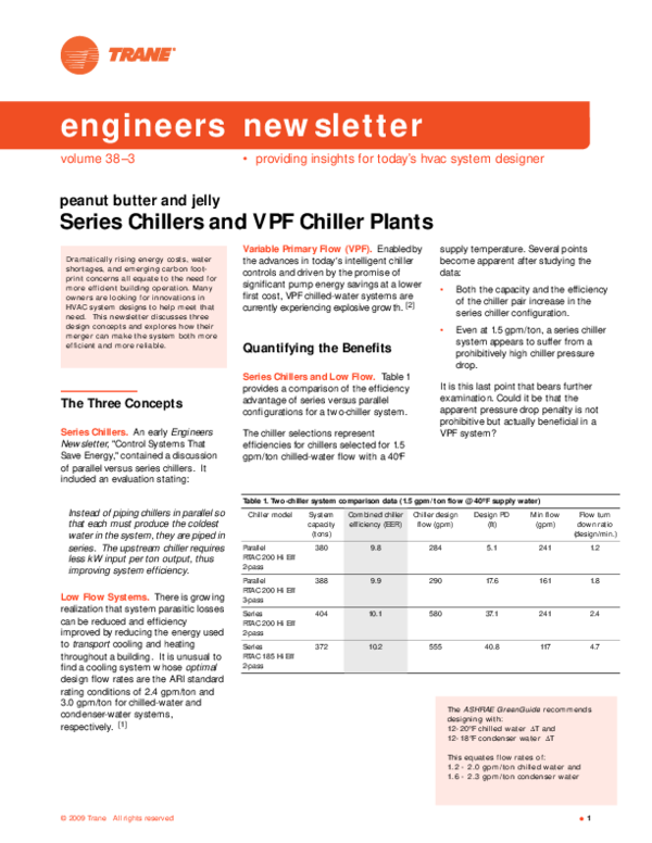
supply temperature. Several points
become apparent after studying the
data:
•
Both the capacity and the efficiency
of the chiller pair increase in the
series chiller configuration.
•
Even at 1.5 gpm/ton, a series chiller
system appears to suffer from a
prohibitively high chiller pressure
drop.
Quantifying the Benefits
Series Chillers and Low Flow. Table 1
provides a comparison of the efficiency
advantage of series versus parallel
configurations for a two-chiller system.
The chiller selections represent
efficiencies for chillers selected for 1.5
gpm/ton chilled-water flow w ith a 40°F
It is this last point that bears further
examination. Could it be that the
apparent pressure drop penalty is not
prohibitive but actually beneficial in a
VPF system?
Table 1. Two-chiller system comparison data (1.5 gpm/ ton flow @ 40ºF supply water)
Instead of piping chillers in parallel so
that each must produce the coldest
water in the system, they are piped in
series. The upstream chiller requires
less kW input per ton output, thus
improving system efficiency.
Low Flow Systems. There is grow ing
realization that system parasitic losses
can be reduced and efficiency
improved by reducing the energy used
to transport cooling and heating
throughout a building. It is unusual to
find a cooling system w hose optimal
design flow rates are the ARI standard
rating conditions of 2.4 gpm/ton and
3.0 gpm/ton for chilled-water and
condenser-water systems,
respectively. [1]
Chiller model
System
capacity
(tons)
Combined chiller
efficiency (EER)
Chiller design
flow (gpm)
Design PD
(ft)
M in flow
(gpm)
Flow turn
dow n ratio
(design/min.)
Parallel
RTAC 200 Hi Eff
2-pass
380
9.8
284
5.1
241
1.2
Parallel
RTAC 200 Hi Eff
3-pass
388
9.9
290
17.6
161
1.8
Series
RTAC 200 Hi Eff
2-pass
404
10.1
580
37.1
241
2.4
Series
RTAC 185 Hi Eff
2-pass
372
10.2
555
40.8
117
4.7
The ASHRAE GreenGuide recom m ends
designing wit h:
12- 20°F chilled wat er ΔT and
12- 18°F condenser wat er ΔT
This equat es flow rat es of:
1.2 - 2.0 gpm / t on chilled wat er and
1.6 - 2.3 gpm / t on condenser wat er
© 2009 Trane
All rights reserved
●
1
�Two come to mind. One would be the
dreaded "Low Delta T" syndrome. One
of the commonly touted advantages of
VPF is that chillers can be
"overpumped" in VPF systems to
prevent the premature operation of
additional chillers just to satisfy system
flow. This compensates for low delta T
from the chiller-sequencing point-ofview. However, the system pumps still
expend extra energy moving additional
water through the system. VPF cannot
compensate for the pumping energy
penalty of low delta T.
Figure 1. Ideal VPF flow relationship
2500
flow
2000
1500
2 chiller
1 chiller
0
10
20
30
40
50
60
80
90
100
90
100
90
100
Figure 2. Actual VPF flow relationship: 2.5 TD ratio
2500
2000
Chiller 1
capacity (tons)
design flow (gpm)
min. flow (gpm)
turndown
500
1000
400
2.5:1
1500
two chiller
min. flow
1000
one chiller
min. flow
2 chiller
1 chiller
500
0
10
20
30
40
50
60
70
80
system load
Figure 3. Actual VPF flow relationship: 1.4 TD ratio
2500
flow
2000
Chiller 1
capacity (tons)
design flow (gpm)
min. flow (gpm)
turndown
500
1000
700
1.4 :1
two chiller
min. flow
1500
1000
one chiller
min. flow
2 chiller
1 chiller
500
Figure 3 show s the same system's
actual pump flow (including the chiller's
minimum flow ) but this time based on
chillers w ith a 1.4:1 flow TD ratio.
70
system load
In a VPF system, the pumps must
provide enough flow to meet the
greater of system flow or the chiller’s
minimum flow requirements.
Figure 2 show s the same system's
actual pump flow (including the chiller's
minimum flow ) based on chillers w ith a
2.5:1 flow turndow n (TD) ratio.
500
100
500
A second "corrupter" of the system
load/flow relationship can be the
selected chiller's required minimum
flow.
Figure 1 show s the idealized pump
flow for a two-chiller VPF system—
ignoring the chiller's minimum flow.
The pump flow is proportional to the
system load under all conditions.
Chiller 1
capacity (tons)
design flow (gpm)
1000
flow
VPF: Flow Considerations. VPF
systems save considerable system
energy primarily because the flow
varies proportionally to the system
load. If something were to corrupt this
relationship it would adversely impact
the expected energy savings. What
are some corrupting influences?
0
10
20
30
40
50
60
70
80
system load
With this in mind, if we look back at the
Table 1 chiller selections, another
conclusion becomes evident.
•
2
The extremely low-flow TD ratio for
the parallel chillers w ith 2-pass
evaporators in the first row would
not work well in a VPF system.
●
Trane Engineers New sletter volume 38–3
providing insights for today’s HVAC system designer
�It's clear: a low turndow n ratio
significantly impacts VPF pump
operation. But is lack of adequate
chiller evaporator flow turndow n a real
concern? It depends on the chiller
type, but the general answer is yes and
it w ill only get worse due to the need
for more efficient systems.
M anufacturers are being driven to
produce more and more efficient
chillers to meet code or customer
requirements. A common way to
improve chiller efficiency is to increase
the heat exchanger’s surface area—
add more tubes to the evaporator and/
or condenser. M ore tubes result in a
greater flow area and a lower design
fluid velocity. A higher minimum flow is
required to maintain sufficient fluid
velocity to prevent laminar flow
conditions. Laminar operation can lead
to unstable chilled-water temperature
control that can be hazardous to the
chiller.
Additionally, engineers are follow ing
industry "best practices" and designing
more efficient systems through the
use of lower system and chiller design
flow rates. Systems at 2.0, 1.7 or even
1.5 gpm/ton are becoming the norm,
rather than the exception. While
lowering the design flow is good for
system efficiency, it reduces the
available TD ratio for a given chiller.
Applied centrifugal chillers typically
have many heat exchanger options so
that an adequate TD ratio can be
selected. However, it's becoming
common to see packaged chiller
selections w ith very low TD ratios.
This can make them difficult to apply in
parallel chiller/VPF systems.
•
Include the requirement to submit
chiller minimum and maximum
rated flow s as a line item in the bid
package.
•
Don't specify chillers w ith
excessive capacity safety factor.
•
Consider applying the chillers in a
series configuration.
•
Remember that series chiller
system flow rate-of-change
limitations are set by the chiller’s
limitations just as in parallel VPF
systems.
Impact
Impact of Low Turndow n and
Bypass Selection and Control. In
addition to the pumping energy impact,
a high bypass flow requirement such
as show n in Figure 3 (due to a low TD
ratio) forces the selection of a relatively
large VPF bypass line and control valve.
The required range of control for both
flow and pressure makes stable control
more challenging. When a second
chiller is added, the bypass valve must
open quickly at a relatively low system
differential pressure to allow sufficient
flow to keep the operating chiller above
its minimum flow. The same valve
must also stably control flow at higher
system pressures w hen only a small
amount of bypass is required to keep
multiple chillers operating above their
minimum flow requirements.
VPF Chiller Requirements. How can
a designer ensure that the chillers
applied in a VPF have sufficient flow TD
to work well in a VPF design? There are
several steps that can be taken.
•
Evaluate the bypass flow
requirement w ith different chillers
running, across the full system load
spectrum.
•
Include the requirement for a
minimum TD ratio as part of the
chiller specification.
VPF Flow w ith Series Chiller. Figure
4 plots the pump flow for the same
chillers show n in Figure 3 but in a
series configuration. In the series
configuration, the chillers have an
effective 2.8:1 TD ratio w hen both
chillers are operating. We see that the
operating curve looks quite different.
Some bypass flow is still required
during periods of very low load w hen a
single chiller is operating. However, all
bypass flow is eliminated w hen two
are operating.
System Power for VPF w ith Series
Chillers. In systems w ith constant
flow through the chillers' evaporators,
designers often specify maximum
acceptable pressure drops. The design
flow pressure drop through a pair of
chillers in series is likely to be much
higher than w hat is considered
acceptable in a parallel system.
Figure 4. Series chiller VPF flow relationship: 1.4 TD ratio
2500
2000
flow
However, this might be a perfect
selection in a constant-flow system for
reduced design pump power.
Chiller 1
500
capacity (tons)
design flow (gpm) 1000
700
min. flow (gpm)
2.8 :1
turndown
1500
1000
2 chiller
1 chiller
500
0
10
20
30
40
50
60
70
80
90
100
system load
providing insights for today’s HVAC system designer
Trane Engineers New sletter volume 38–3
●
3
�Table 2 compares the system energy
use at different load points for the 3pass chillers in parallel compared to the
2-pass chillers in a series configuration.
Note: These specific 2-pass chillers
should not be used in parallel in a VPF
system w ith a 1.5 gpm/ton design flow
because of poor flow TD, and the
resultant high bypass flow
requirement.
This comparison demonstrates that the
series chiller configuration has a better
system COP at all load points. Even
w ith a 20 ft higher system pressure
drop at design load, it uses less
energy!
This is a direct result of the chiller's
greater combined efficiency as well as
the decreased bypass flow at part-load
conditions.
Sequencing lag chillers on and off to
match the building load can use the
identical logic that a parallel VPF
system uses. Deviation in system
chilled-water supply temperature is a
simple and robust way to decide w hen
to add a chiller. Chiller load, as
measured by chiller RLA or kW, is a
reliable and repeatable indication of the
point to subtract a chiller from
operation.
1. If one chiller is operating, it is given
the system setpoint.
2. If both chillers are operating:
(a) the dow nstream chiller is given
the system setpoint.
(b) the upstream chiller is given a
setpoint that results in each
chiller carrying one half the
instantaneous load.
The equation for the upstream chiller's
setpoint is based on chilled-water
return temperature and desired chilledwater supply temperature and
calculated simply:
CHSP up
⎛ CHRT − CHSP sys
= CHRT + ⎜⎜
2
⎝
⎞
⎟
⎟
⎠
W h e n N OT t o u se se r ie s ch ille r s.
Alt hough a series chiller configurat ion
saves energy and m akes sense in m any
cases, t here are t im es when it should
not be applied.
The setpoint is periodically recalculated
and sent to the chiller. The chiller
controls its ow n loading.
1. Syst em s wit h design flow rat es
great er t han 1.5 gpm / t on are
probably not good candidat es
because of chiller pressure drop. I t 's
best t o st art wit h a high- efficiency
low- flow syst em design t o opt im ize
pum ping power.
CHSPup Upstream chilled-water
setpoint
Control of Series/ VPF
Chiller Plants
CHRT
Some ow ners and engineers shy away
from series chiller plants because they
are unsure of the system control
requirements. In fact, the only
additional series plant control
requirement is the reset of the
upstream chiller's leaving chilled-water
setpoint to equalize chiller loading. The
three rules for chiller setpoint are
actually quite straightforward.
Actual chilled-water system
return temperature
2. The cont rol int eract ion bet w een
chillers wit h st ep- loading
com pressors ( m ult iple scrolls) can
result in undesirable com pressor
cycling. St andard st ep- loading
chillers should not be applied in
series.
CHSPsys Chilled-water system
supply setpoint
3. If there is a failure of a chiller or
controller, the operating chiller(s)
defaults to the system setpoint.
3. Const ant - flow syst em s are not
t ypically good candidat es for series
chillers.
Table 2. System energy use comparison
Load
Parallel RTAC 200 3-pass chiller
Tons
4
●
Series RTAC 200 2-pass chiller
Pumping
PD
Pump
kW
Chiller
Total
Sys
kW
kW
COP
Tons
Pumping
PD
Pump
kW
Chiller
kW
Total
kW
Sys
COP
COP
Increase
%
100
388
70
10
472
482
2.83
404
90
14
482
496
2.87
1.3
90
349
60
8
396
404
3.04
364
76
10
400
411
3.11
2.6
80
310
51
6
326
332
3.29
323
63
8
323
331
3.44
4.4
70
272
43
4
260
264
3.62
283
52
6
265
271
3.67
1.6
60
233
36
3
208
211
3.88
242
43
4
207
211
4.04
4.0
50
194
31
3
160
163
4.19
202
35
3
164
167
4.26
1.9
40
155
27
2
123
124
4.39
162
29
2
121
123
4.62
5.3
30
116
24
1
99
100
4.09
121
25
1
98
99
4.31
5.3
20
78
21
1
85
86
3.18
81
22
1
84
85
3.36
5.7
10
39
20
1
71
72
1.90
40
20
1
70
71
2.01
5.7
Trane Engineers New sletter volume 38–3
providing insights for today’s HVAC system designer
�See the Engineers New sletter on VPF
systems for more details on chiller
sequencing. [2]
Figure 5. Series chiller pairs
Figure 6. Series plants
passing a non-operating chiller w ill
provide additional pump savings, the
added piping and control complexity
may not justify the savings.
Figure 7. Series chiller pair w ith service
bypass
M ore Than Two Chillers? Odd
numbers of chillers are difficult to deal
w ith in a series configuration. Except
for some very low flow process
applications, the system pressure drop
for three chillers in series becomes
untenable. The solution is to resize the
chillers so that an even number can be
applied.
If a system requires four, six or more
chillers, one possible system
configuration is series "chiller pairs"
situated in parallel as show n
in Figure 5.
An alternate, and more versatile,
approach of "series plants," show n in
Figure 6, should be considered.
A "series-plant" configuration provides
several benefits:
•
One chiller out of service doesn't
affect the operation of other
chillers.
•
The operation of upstream and
dow nstream chillers can be mixmatched for better flexibility and
reliability.
•
Chiller Bypass Piping. Discussions of
series chillers often include the issue of
including extra bypass piping around
each chiller. An example of such piping
is show n in Figure 7.
The cooling system in question
serves a critical load that cannot
tolerate a short-term scheduled
shutdow n of both chillers in a
series pair.
•
One chiller must be available for
comfort conditioning at all times.
There are two potential reasons to
include chiller bypass piping.
The first is to eliminate a non-operating
chiller's pressure drop from a series
pair of chillers. However, as show n
previously in Table 2, the pumping
energy penalty at such part load
conditions is minimal. While by-
providing insights for today’s HVAC system designer
Second, including chiller bypass piping
w ith manual isolation valves to enable
serviceability may be desired for the
follow ing reasons:
Chiller service external to the
refrigeration system may be performed
w ith chilled water flow ing through the
evaporator heat exchanger. However,
the refrigeration system must never be
exposed to ambient atmosphere w ith
active chilled-water flow. M oisture can
enter the chiller's exposed refrigeration
system and rapidly cause corrosion or
contamination of hygroscopic oils used
w ith many current refrigerants. Also,
Trane Engineers New sletter volume 38–3
●
5
�proper evacuation of a refrigeration
system is practically impossible w ith
active chilled-water flow.
Figure 8 - Free-cooling heat exchanger in
upstream position.
The key to answering the question of
w hether to apply a chiller w ith a heatrecovery condenser or a completely
separate heat-recovery chiller is a
building hourly energy analysis w ith a
program such as Trane TRACE™. Such
an energy analysis w ill reveal if the
heating and cooling load magnitude
and occurrence are favorable to the
application of a double-bundle
condenser chiller. Relatively similar
loads work well w ith double-bundle
heat-recovery chillers. However, if the
Series Unlocks Other
System Efficiency Options
There are several energy-saving
system options that can work very well
in conjunction w ith a series/VPF
system.
Series and "Free" Cooling. Use of
cold condenser water, available during
periods of low wet-bulb temperatures,
to produce chilled water via plate-andframe heat exchangers or refrigerant
migration w ithin a chiller are methods
to significantly reduce system energy
use.
An excellent strategy for applying a
refrigerant-migration, free-cooling
chiller in a series system is to locate it
in the upstream position. See
reference [3] for more information.
A free-cooling chiller can provide 30 to
40 percent of its design tonnage,
depending on the operating conditions.
When the refrigerant-migration chiller
cannot meet the full building load, the
dow nstream chiller can be started to
augment the system cooling capacity.
This coincident free and mechanical
cooling greatly extends the freecooling operating hours and energy
savings. Since the free cooling is
provided through an option on a chiller,
there is no additional space required in
the equipment room and minimal
increase in maintenance.
Another free-cooling option is the
application of a dedicated free-cooling
heat exchanger in parallel w ith the upstream chiller as show n in Figure 8.
While this option requires additional
equipment room space and
maintenance, it can be designed for
greater free-cooling capacity than a
refrigerant-migration chiller can
provide. It also may be the only waterside free-cooling option for systems
w ith chiller types that do not offer a
6
●
Trane Engineers New sletter volume 38–3
dow nstream chiller to carry any leftover
cooling load. [4]
Figure 9. Heat-recovery chiller w ith doublebundle condensers
free-cooling option. Because of its
upstream position, the heat exchanger
also provides for coincident free,
mechanical cooling, increasing the
free-cooling energy savings.
Series and Heat Recovery. A chiller
w ith a dedicated heat-recovery
condenser (sometimes called a doublebundle condenser) or an additional,
properly sized, heat-recovery chiller
works very well in a series/VPF plant in
the upstream position (see Figure 9).
The upstream positioning benefits
from the warmest system return-water
temperature for more efficient heatrecovery chiller operation.
There is a grow ing synergy between
the application of chiller heat-recovery
and high-efficiency heating systems.
Condensing boilers require lower
heating system water temperatures to
achieve their efficiency potential. As a
result, heating system design
temperatures of 180°F are being
replaced w ith 105°F to 130°F. M any
chiller types can provide efficient heat
recovery in conjunction w ith lower
heating temperatures.
Se r ie s cou n t e r flow .
The nat ural progression for increasing
t he efficiency of wat er- cooled series/
VPF syst em s is configuring t he
condensers in series as well as t he
evaporat ors. This is a concept know n as
" Series- Count er."
For a det ailed analysis of t he
perform ance of a series- count erflow
chiller plant , see t he ASHRAE Journal
June 2002 art icle: " Series- Series
Count erflow for Cent ral Chilled- Wat er
Plant s" by Groenke and Schwedler.
As w ith the free-cooling application, it
is a simple matter to optimize the
system operation by controlling the
upstream heat-recovery chiller for
optimum operation and allow the
providing insights for today’s HVAC system designer
�heating load magnitude and
occurrence result in the available
heating load to the chiller being a small
fraction of its cooling capacity, then
applying a properly sized, dedicated
heat-recovery chiller may likely be a
better option.
M ore to Come...
Peanut butter & jelly,
Bacon & eggs,
Table & chairs,
Series chillers & VPF...
•
High efficiency due to the
upstream chiller operating at an
elevated temperature.
•
Simple control and loading of either
chiller.
•
Ability to apply other energy-saving
options such as "free cooling" or
heat recovery.
By Lee Cline, application engineer, and Jeanne
Harshaw, Trane. You can find this and previous
issues of the Engineers New sletter at
w w w.trane.com/engineersnew sletter. To
comment, e-mail us at comfort@trane.com
The benefits of efficiency and
controllability, along w ith the natural
performance enhancing fit of free
cooling or heat recovery, is resulting in
rapid grow th and application of these
system concepts.
Systems using series chillers in
conjunction w ith variable primary flow
have the follow ing advantages:
Air-Handling Systems,
Energy and IAQ
N ovem ber 4
References.
Foot not es:
There are many things that naturally
complement each other. M any
designers and contractors are finding
this true of series chillers and variable
primary flow w hen a high-efficiency,
chilled-water system is the goal.
Engineers
N ew sletter
LIV E!
[1] M . Schw edler, 1997. "How Low-Flow Systems
Can Help You Give Your Customers What They
Want." Engineers New sletter, volume 26-2.
mark your calendar!
2 010 Schedule
Fans in Air-Handling Systems
[2] M . Schw edler, 2002. "Variable-Primary-Flow
Systems Revisited." Engineers New sletter,
volume 31-4.
M arch
[3] S. Hanson, 2008. " ’Free’ Cooling Using Water
Economizers." Engineers New sletter, volume
37-3.
Central Geothermal Systems
[4] M . Schw edler, 2007. "Waterside Heat
Recovery." Engineers New sletter, volume 36-1.
M ay
ASHRAE 90.1-2010
October
contact your local Trane office for details
•
Great fit w ith "reduced flow "
systems as recommended by the
ASHRAE GreenGuide.
•
Significant ability to accommodate
reduced flow rates at part load
conditions.
•
M aximized pump savings due to
minimal requirement for bypass
flow.
providing insights for today’s HVAC system designer
Trane Engineers New sletter volume 38–3
●
7
�educat ional resources
www.Trane.com/bookstore
application manuals are comprehensive reference
guides that can increase your working know ledge of
commercial HVAC systems. Topics range from
component combinations and innovative design
concepts to system control strategies, industry issues,
and fundamentals. Visit w w w.trane.com/bookstore.
Chiller System Design and Control
examines chilled-watersystem components, configurations, options, and control strategies. The
goal is to provide system designers w ith options they can use to satisfy
the building ow ners’ desires. (SYS-APM 001-EN, M ay 2009)
Chilled-Water VAV Systems focuses on chilled-water, variableair-volume (VAV) systems. These systems are used to provide comfort in
a w ide range of building types and climates. To encourage proper design
and application of a chilled-w ater VAV system, this guide discusses the
advantages and draw backs of the system, review s the various
components that make up the system, proposes solutions to common
design challenges, explores several system variations, and discusses
system-level control.(SYS-APM 008-EN, August 2009)
air conditioning clinics are a series of educational
presentations that educate readers about HVAC fundamentals,
equipment, and systems. The recently revamped series now includes
full-color student workbooks, w hich can purchased individually.
engineers new sletters are published as a free service to
building professionals and are archived at w w w.trane.com/
engineersnew sletter. Each issue tackles a timely topic related to the
design, application and/or operation of commercial, applied HVAC
systems.
engineers new sletter live is a series of 90-minute recordings
that presents technical and educational information on specific
aspects of HVAC design and control. Visit w w w.trane.com/ENL for
specific program details or to check out the 2010 schedule.
Trane,
A business of Ingersoll-Rand
For m ore inform ation, contact your local Trane
office or e-m ail us at com fort@trane.com
8
●
Trane Engineers New sletter volume 38–3
Trane believes the facts and suggestions presented here to be accurate. However, final design and
application decisions are your responsibility. Trane disclaims any responsibility for actions taken on
the material presented.
ADM -APN033-EN (September 2009)
�
 JOSE LUIS Huaman