Method Statement for Construction of Balanced Cantilever Bridge by using
Cast-in-Place Segmental PSC Box-Girders along with reports on Structural
Analysis and Design
Balanced Cantilever Bridge
PART – I
Method Statement for Construction of Balance Cantilever Segments of
Balanced Cantilever Bridge
Page - 1
PART – II
Method Statement for Construction of Open Foundation, Piers and
Superstructure of Balanced Cantilever Bridge Page - 51
PART – III Method Statement for Construction of Hammer Head at the Fixed Pier of
Balanced Cantilever Bridge
Page - 77
PART – IV Method Statement for Construction of Tack Coat and Bituminous Concrete
for Balanced Cantilever Bridge
Page – 102
References
Page – 111
A Technical Paper by Sandipan Goswami
(References are given at the end of this document, Page 111, followed by Design Summary with
AASHTO, BS/Eurocode2 and IS/IRC)
�To master the concept the Analysis and Design of a Balanced-Cantilever
Bridge default sample design data may be processed by downloading
software ‘ASTRA Pro Premium’ from website www.techsoftglobal.com.
`
‘ASTRA Pro – Premium’ software provides a set of (100+) Sample Editable CAD
Drawings for construction of Balanced Cantilever Bridge.
Learning concept for “Model Analysis-Design-Construction”
�Foreword
Article on Method Statement for Construction of Balanced Cantilever Bridge by using
Cast-in-Place Segmental PSC Box-Girders along with reports on Structural Analysis and
Design
This article contains the ‘Method Statement’ about the work sequence for the construction of
Open Foundation, Piers and Superstructure of Balanced Cantilever Bridge. For the
design the software ‘ASTRA Pro Premium’ is used, and a set of editable sample drawings are
provided with software ASTRA Pro Premium, this software may be downloaded from its
company website www.techsoftglobal.com. After downloading the software may be installed in
the system. The software provides analysis, design on analysis and sample editable CAD
drawings under the section ‘Drawings’.
In analysis suite, there are ‘Normal Analysis’, ‘Stage Analysis’ and ‘Dynamic Analysis’, out of
these analysis the ‘Normal Analysis’ is mandatory other analyses are optional. The ‘Stage
Analysis’ is also known as Non Linear Analysis or P-Delta Analysis or Force Deflection
Analysis. The analysis may be carried out for 5-stages each shall be of 20 years. If the design life
of the bridge is 100 years then each five stages will give forces and deflections by applying Dead
Load, Superimposed Dead Load and Live on the deflected shape of the previous stage.
Initially (immediately after construction) if the allowable deflection for a bridge span is
‘Span/1500’ that is to be tested by on-site load test on the bridge. If the deflection is within
span/1500 then the load capacity rating capacity is partly alright. Next, upon unloading the
bridge span in stages if the deflection recovery is found up to 85%, then the load capacity rating
capacity is finally alright.
This load test is to be conducted after 20, 40, 60, 80, and 100 years of age of the bridge, if the
respective deflections are within the values found by stage analysis then the condition of the
bridge is alright at that respective ages, otherwise other tests as NDT may be carried out and
decision may be taken whether to go for rehabilitation or replacement of the bridge. The
deflection may by deformation in the superstructure, substructure or bearing and that may be
observed by reading from sensors attached at strategic locations of the bridge.
Next, user has to go to section ‘Design Forces’ in ASTRA Pro and select ‘Normal Analysis’, and
then select ‘Design on Analysis’ to get the design results in respect of selected design forces. The
sample CAD drawings may be edited as necessary, as per user’s design data and the design
results.
The design reports in AASHTO-LRFD, BS/Eurocode2 and IS/IRC are given, at the end of the
‘Method Statement’ and next the ‘References’ are given to assist the users further.
Sandipan Goswami
Email: sandipanmails@gmail.com
�Academic Text Book with Real Design Applications
Text Book title: Computer Aided Bridge Engineering,
Author: Sandipan Goswami,
Pages: 381,
Publisher: Nova Science Publishers, New York, USA,
ISBN: 978-1-68507-413-5
Publisher, for Book, Software and Tutorial videos,
Web page: https://novapublishers.com/shop/computer-aided-bridge-engineering-detaildesign-of-pre-stressed-concrete-i-girder-box-girder-bridges/
Contact: Ms. Lisa Gambino, Nova Science Publishers, for price discount offer,
Email: marketing@novapublishers.com
Ref. Sandipan Goswami, (Author)
�Method Statement for Construction of Balanced Cantilever Bridge
by using Cast-in-Place Segmental PSC Box-Girders along with
reports on Structural Analysis and Design,
Article by Sandipan Goswami
PART – I
Method Statement for Construction of Balance Cantilever Segments of
Balanced Cantilever Bridge
TABLE OF CONTENTS
SL. NO.
1.
2.
3.
4.
5.
6.
7.
8.
9.
10.
SECTION NAMES
PAGE NO.
SCOPE OF WORK
INTRODUCTION
RESPONSIBILITY
CODES AND SPECIFICATIONS
MATERIALS REQUIRED
RECORDS AND DOCUMENTATION
REFERENCE DOCUMENTS / DRAWINGS
MAJOR EQUIPMENTS
WORK SEQUENCE
SAFETY PRECAUTIONS AND MEASURES
1
2
2
4
5
5
6
7
8
49
1. SCOPE OF WORK
Location
Start Chainage (Km)
End Chainage (Km)
Length (m)
Balance Cantilever portion
Foundation
Piers
Hammer Heads (at fixed & free
piers)
Pier caps (at free piers)
Spans
Balance cantilever segments
Stitch segments
Extended portion
Foundation
Piers
Abutments
Pier caps / Abutment caps
Spans
Area Name and District Name.
LHS
RHS
Total
2634km+122.5m 2634km+082.5m
2635km+397.5m 2635km+377.5m
1275 m
1295 m
13
13
13
13
26
26
12
12
24
5
10 (98.00 m)
4 (53.75 m)
200
10
5
10 (98.00 m)
4 (53.75 m)
200
10
10
400
20
6
4
2
6
4 (20.00 m)
7
5
2
7
5 (20.00 m)
13
9
4
13
9
28
1
�Method Statement for Construction of Balanced Cantilever Bridge
by using Cast-in-Place Segmental PSC Box-Girders along with
reports on Structural Analysis and Design,
Article by Sandipan Goswami
2. INTRODUCTION
This Method Statement describes the construction sequence of Balance cantilever segments of
Balanced Cantilever Bridge superstructure by Cantilever Form Traveler (CFT). It also describes
the methods adopted, equipments, material details and relevant IS codes, inspection details and
safety and health measures.
3. RESPONSIBILITY
i.
Supervisor shall be responsible for managing all equipment, machineries and
workmen for all subsidiary activities.
ii.
Section Engineer/Manager shall be responsible for all activities of the works
including reinforcement cutting/bending/fixing, Shutter fixing and concreting works.
iii.
Execution Engineer shall be responsible for the works as per the technical
specifications & drawings.
iv.
QA/QC Engineer shall be responsible for ensuring the quality of work as per
specifications.
v.
Survey Engineer shall be responsible for ensuring correct alignment and elevation of
structure as per the drawings.
vi.
Safety Engineer shall be responsible to ensure safety of workers during the progress
of work.
vii.
Planning engineer shall be responsible for ensuring the work is going as per Schedule
and planned sequence / methods.
viii.
Project in charge shall be responsible for overall completion of Project within time.
2
�Method Statement for Construction of Balanced Cantilever Bridge
by using Cast-in-Place Segmental PSC Box-Girders along with
reports on Structural Analysis and Design,
Article by Sandipan Goswami
Figure I-1 (A) & (B) - General Arrangement Drawing of Viaduct-2
(Longitudinal Elevation, Reference Drawing: GAD-01)
Figure I-2 - Cross section of balance cantilever segments
(Reference Drawing: GAD-01)
3
�Method Statement for Construction of Balanced Cantilever Bridge
by using Cast-in-Place Segmental PSC Box-Girders along with
reports on Structural Analysis and Design,
Article by Sandipan Goswami
4. CODES AND SPECIFICATIONS
Construction is covered under Specifications for Roads and Bridges (MoRTH) 5th Revision as
below (Relevant standards may be followed for construction in different countries):
Sr. No.
Section
1
1000
Clause
Materials for Structures
Clause 1006 - Cement,
1007 – Coarse Aggregate,
1008 – Fine Aggregate,
1009 - Steel,
1010 - Water,
1011 – Timber,
1012 – Concrete Admixtures,
1014 – Storage of Materials,
1015 – Tests and Standard of Acceptance
2
1500
Formwork
3
1600
Steel Reinforcement
4
1700
Structural concrete
5
1800
Prestressing
6
1900
Structural Steel
7
2300
Superstructure
IS:1343 – Pre-stressed concrete Code of Practice,
IS14268 – Uncoated stress relieved Low Relaxation Seven ply strand for pre-stressed concreteSpecification,
IRC-18-200 – Design criteria Pre-stressed Concrete Road Bridge (Post tensioned Concrete).
4
�Method Statement for Construction of Balanced Cantilever Bridge
by using Cast-in-Place Segmental PSC Box-Girders along with
reports on Structural Analysis and Design,
Article by Sandipan Goswami
5. MATERIALS REQUIRED
Materials required for construction of the Balanced Cantilever Bridge is to be as per relevant
specifications. However, for cross reference the relevant Indian standards are given as follows:
Materials Used
Source
Cement
Ambuja OPC 53 grade,
Ultra Tech OPC 53 grade,
or other approved make.
Water
Reinforcement
Water from Bhawli Dam
M/S SAIL & M/S JSW
Coarse Aggregate
Stone Crusher
Crusher Sand (Wash Sand)
Admixture
Concrete
Crushing aggregate
excavated from site
Crystalline Admixture,
Corrosion Inhibitor
Batching Plant
Sheathing ducts
Anchorages
HT Strands
Specifications
IS 4031 -1988, IS 4032 -1985,
IS 12269 - 1987
As per IS - 2000, IS 3025
As per IS 1786 :2008
As per IS 383-1970, IS 2386 1963
As per IS 383
IS 9103
IS 456: 2000
EFNARC
Morth Specifications Section
1803.2
Morth Specifications Section
1803.3
IS14268
6. RECORDS AND DOCUMENTATION
Sr. No.
1
2
3
4
5
6
7
Documents
Material and Mix design approval
Request for Inspection
Inspection Check List
Approval to Place concrete
Concrete Batch Slip
Concrete Pour record
Stressing record
5
�Method Statement for Construction of Balanced Cantilever Bridge
by using Cast-in-Place Segmental PSC Box-Girders along with
reports on Structural Analysis and Design,
Article by Sandipan Goswami
7. REFERENCE DOCUMENTS / DRAWINGS (Available with ASTRA Pro Software)
Drawing Nos.
01 (1 OF 3) GAD
01 (1 & 2) SUPERSTRUCTURE
08 (1 to 4) SUPERSTRUCTURE
02 (1 & 2) SUPERSTRUCTURE
09 (1 to 4) SUPERSTRUCTURE
10 (1 & 2) SUPERSTRUCTURE
11 (1 to 3) SUPERSTRUCTURE
12 (1 & 2) SUPERSTRUCTURE
13 (1 to 3) SUPERSTRUCTURE
14 (1 & 2) SUPERSTRUCTURE
15 (1 to 3) SUPERSTRUCTURE
16 (1 to 2) SUPERSTRUCTURE
17 (1 to 3) SUPERSTRUCTURE
18 (1 & 2) SUPERSTRUCTURE
19 (1 & 2) SUPERSTRUCTURE
20 (1 to 3) SUPERSTRUCTURE
21 (1 to 3) SUPERSTRUCTURE
22 (1 to 3) SUPERSTRUCTURE
23 (1 to 3) SUPERSTRUCTURE
24 (1 & 2) SUPERSTRUCTURE
25 (1 & 2) SUPERSTRUCTURE
26 (1 to 4) SUPERSTRUCTURE
05 (1 to 6) SUPERSTRUCTURE
06 (1 to 3) SUPERSTRUCTURE
Description
General Arrangement Drawing
Dimension details of Monolithic Span
Reinforcement Details of Monolithic Pier Head, Seg. S1
Dimension Details of Free Pier Span
Reinforcement Details of Free Pier Head, Seg. S1
Reinforcement Details of Segment S2 in All Spans
Reinforcement Details of Segment S3 in All Spans
Reinforcement Details of Segment S4 in All Spans
Reinforcement Details of Segment S5 in All Spans
Reinforcement Details of Segment S6 in All Spans
Reinforcement Details of Segment S7 in All Spans
Reinforcement Details of Segment S8 in All Spans
Reinforcement Details of Segment S9 in All Spans
Reinforcement Details of Segment S10 In All Spans
Reinforcement Details of Segment S4 of Anchor Span
Reinforcement Details of Segment S5 of Anchor Span
Reinforcement Details of Segment S6 of Anchor Span
Reinforcement Details of Segment S7 of Anchor Span
Reinforcement Details of Segment S8 of Anchor Span
Reinforcement Details of Segment S9 of Anchor Span
Reinforcement Details of Segment S10 of Anchor Span
Reinforcement Details of Ed1 Segment for all Expansion
Joint Piers
Pre-stressing Details of Deck Cables In All Spans
Pre-stressing Details of Soffit Cables In All Spans
6
�Method Statement for Construction of Balanced Cantilever Bridge
by using Cast-in-Place Segmental PSC Box-Girders along with
reports on Structural Analysis and Design,
Article by Sandipan Goswami
8. MAJOR EQUIPMENTS
The major equipments to be deployed are the followings:
Sr. No.
Description
1
Pick & carry crane
2
Trailer
3
Crane (min. 150 MT capacity)
4
Concrete pump
5
Transit mixers
6
Curing pump
7
Bar Cutting Machine
8
Bar Bending Machine
9
Welding sets
10
Batching Plant
11
Diesel Generator
12
Compressor
13
Needle vibrators
14
Pre-stressing jacks
16
Power pack
15
Grout pump
16
Survey equipments
17
Cantilever Form Traveler (CFT)
7
�Method Statement for Construction of Balanced Cantilever Bridge
by using Cast-in-Place Segmental PSC Box-Girders along with
reports on Structural Analysis and Design,
Article by Sandipan Goswami
9. WORK SEQUENCE
Figure I-3 - Longitudinal Section of Balance Cantilever Segments
i.
Superstructure construction in Balanced Cantilever Bridge is done by using Cantilever
Form Traveler (CFT).
ii.
The cross-sectional dimensions of segments vary from Segments S1 to S10.
iii.
Segments of length of 5m are cast by using Cantilever Form Traveler (CFT). Prestressing is done after casting every segment. The reinforcements are continuous through
each segment.
iv.
Segment S1 is cast along with the hammer head on the Pier. Further, from segment S2 to
segment S10 are cast by using the Cantilever Form Traveler (CFT).
v.
Segment S2 with concrete volume of around 73 cum. is the biggest segment cast by using
CFT and S10 is the Stitch segment, which is the smallest of segment with concrete
volume of around 33 cum. The Stitch segment is at the end of a cantilever span on either
side, which is at the middle of each span, where it joins the cantilever span that comes
from opposite direction from the next pier.
8
�Method Statement for Construction of Balanced Cantilever Bridge
by using Cast-in-Place Segmental PSC Box-Girders along with
reports on Structural Analysis and Design,
Article by Sandipan Goswami
Figure I-4 - Section at the end of S2 Segment
Figure I-5 - Section at the end of S9 segment
vi.
To facilitate the CFT operation Sleeve holes of 75mm dia. are to be provided in deck slab
as per the sleeve holes drawing.
vii.
After completion of hammer head, two sets of Cantilever Form Traveler (CFT) are
erected on hammer head.
viii.
Both the CFT sets will cast segments in opposite directions.
ix.
Two balance cantilever arms are connected by a stitch segment. To cast stitch segment,
inner form of CFT is dismantled and conventional shutter arrangement will be provided.
9
�Method Statement for Construction of Balanced Cantilever Bridge
by using Cast-in-Place Segmental PSC Box-Girders along with
reports on Structural Analysis and Design,
Article by Sandipan Goswami
x.
9.1
Cantilever Form Traveler (CFT) is dismantled after completion of stitch segment casting.
Major components of Cantilever Form Traveler (CFT)
Following are the major components of Cantilever Form Traveler (CFT) and their weights:
i. Main Rails:
6.56MT
ii. Main Frames:
6.84 MT
iii. Rear truss:
1.69 MT
iv. Front truss with hangers: 5.5 MT
v. Bottom form:
17 MT
vi. Outer form:
16 MT
vii. Inner form:
8.5 MT
Figure I-6 - Components of CFT
Flat and dry area, should be large enough to accommodate the major CFT components, i.e., the
bottom form and the outer form will be specified to carryout ground assembly of CFT
components before starting the erection work.
10
�Method Statement for Construction of Balanced Cantilever Bridge
by using Cast-in-Place Segmental PSC Box-Girders along with
reports on Structural Analysis and Design,
Article by Sandipan Goswami
All the assembled CFT components are inspected before starting the erection work.
The assembled CFT components are shifted to the lifting location with the help of pick and carry
crane and trailer.
Erection plan shall be prepared before starting the erection. Parameters such as crane position,
boom length, safe working radius and permissible lifting capacity to be decided and accordingly
erection activity to be carried out.
9.2
Erection of Cantilever Form Traveler (CFT)
a) Main rails:
i.
The main rails are assembled on ground and lifted on hammer head with the help of
crane. Each rail consists of two longitudinal beams (left and right), and transverse
connection elements.
ii.
The main function of rail is to facilitate the advancing of form traveler after every
segment casting.
iii.
While positioning the rails on hammer head the longitudinal slope of rails shall be set
parallel to the deck slope (bridge gradient).Whereas in transverse direction both the rails
are maintained at same level at every point.
iv.
Steel packing or wooden packing is provided under the rails for elevation correction.
v.
The main rails are tied to the deck with rail locking beams by PT bar no 7 as shown in
the figure.
11
�Method Statement for Construction of Balanced Cantilever Bridge
by using Cast-in-Place Segmental PSC Box-Girders along with
reports on Structural Analysis and Design,
Article by Sandipan Goswami
Figure I-7 - Main Rail Locking with Deck
Figure I-8 - Main Rails Locked to the Deck
b) Main Frame and Rear Truss:
i. Main frame is ground assembled along with ‘Front Under Carriage’ and ‘Rear Tie Down’
assembly.
ii. During assembly, care is to be taken that all the pins are secured at the end by cotter pins.
The ends of the cotter pins are to be bent properly.
iii. The first main frame is erected and positioned on the rails above the deck. Temporary
supports are provided to keep the main frame stable and vertical.
iv. The crane should hold the main frame until the temporary supports and rear tie down of
main frame is completed.
v. The rear tie down of main frame with deck is done with the help of PT bar no. 1.
vi. The main frame is to be positioned in such a way that the load bearing point is
approximately 500 mm behind the hammer head concrete face.
12
�Method Statement for Construction of Balanced Cantilever Bridge
by using Cast-in-Place Segmental PSC Box-Girders along with
reports on Structural Analysis and Design,
Article by Sandipan Goswami
vii. Second main frame is erected and positioned on the rails above the deck. Temporary
supports are provided to keep the main frame stable and vertical. Rear tie down of main
frame is done.
viii.
The rear truss is erected in three parts, central part and two outer parts and it is connected
with the main frames by pin connection.
ix.
A platform is provided along the main frame such that the tip of main frame can be
accessed, which will be helpful during the front truss erection.
x.
Rear under carriage wheels are connected to both the main frames.
xi.
The rear tie down assembly is secured through the deck using PT bar number 1, bearing
plates and nuts are adequately tightened with spanner. It shall be ensured that the tapered
washers are positioned correctly.
xii.
The main function of the rear tie down system is to resist the overturning of form
traveler.
Figure I-9 - Main Frame and Main Rails
13
�Method Statement for Construction of Balanced Cantilever Bridge
by using Cast-in-Place Segmental PSC Box-Girders along with
reports on Structural Analysis and Design,
Article by Sandipan Goswami
Figure I-10 - Rear Under Carriage
c) Front truss and hangers:
i. Front truss and hangers are assembled on ground and lifted to main frame with the help
of crane and connected with main frame by pin connection.
ii. Platform provided along the main frame will provide access to do the pin connection
between the front truss and the main frame.
14
�Method Statement for Construction of Balanced Cantilever Bridge
by using Cast-in-Place Segmental PSC Box-Girders along with
reports on Structural Analysis and Design,
Article by Sandipan Goswami
iii. Trial assembly of front truss with main frame is to be done on ground to ensure that the
front truss and main frame pin connection is perfect.
Figure I-11 - Front Truss with Hangers
d) Bottom form:
i. Bottom form along with side working platforms and rear working platform is ground
assembled and positioned exactly below its position on Cantilever Form traveler (CFT).
ii. Four chain pulleys each of capacity 10MT are provided to hold the bottom form.
iii. Two of these chain pulleys are provided on front truss and two on rear truss.
iv. Bottom form is lifted by crane up-to soffit slab of segment and four number chain pulleys
are connected. The crane is released only after confirming that all the chain pulleys are
taking the load.
v. PT bars number 6, two from S1 segment soffit slab sleeves and two from front truss
hangers are provided with plates and nuts to hold the bottom form.
15
�Method Statement for Construction of Balanced Cantilever Bridge
by using Cast-in-Place Segmental PSC Box-Girders along with
reports on Structural Analysis and Design,
Article by Sandipan Goswami
Figure I-12 - Bottom form: Plan view
Figure I-13 - Bottom form: Front view
e) Outer form:
i. Outside form (median side and ROW side) are pre-assembled on the ground. It consists
of support console above which support frames are provided to support the form panels.
ii. Casting hangers and launching hangers are provided along with support console. Hangers
facilitate casting of segment and launching of form traveler.
iii. After completion of ground assembly, the outer form is lifted with the help of crane. It is
supported by PT bars, PT bar no. 3 and PT bar no.10 support ‘Outer Form’ through deck
slab sleeves connecting ‘Outer Form Hangers’ and PT bar no. 3 from ‘Front Truss
Hangers’ holds the ‘Outer Form Support Console’.
16
�Method Statement for Construction of Balanced Cantilever Bridge
by using Cast-in-Place Segmental PSC Box-Girders along with
reports on Structural Analysis and Design,
Article by Sandipan Goswami
iv.
The purpose of hangers is to hold the formwork in the correct position during the
concreting process. Hangers simplify the setting up and adjusting the formwork.
v.
Two chain pulleys are provided on ‘Front Truss Hangers’ connecting the ‘Outer Form
Support Console’ to facilitate the vertical adjustments in ‘Outer Form’.
vi.
After erection of ‘Outer Form’ on median side and ROW side, outer vertical web shutter
panels are erected and connected with ‘Outer Form’ by pin connection on both the sides.
Figure I-14 - Outer form
f) Upper working platform:
i. The upper working platform frame shall be preassembled on the ground and grating is
provided for access.
ii. PT bar number 8 (four numbers) is provided from nose truss.
iii. The assembly is lifted with the help of crane and supported by PT bar number 8.
17
�Method Statement for Construction of Balanced Cantilever Bridge
by using Cast-in-Place Segmental PSC Box-Girders along with
reports on Structural Analysis and Design,
Article by Sandipan Goswami
g) Lower working platform:
i. The lower working platform is also to be pre-assembled on the ground and lifted in one
piece.
ii. Two chain pulleys are connected from upper working platform to support lower working
platform.
iii. The chain pulley is to facilitate the lowering platform along with the bottom form during
launching of CFT.
iv. Also the lower working platform is to be connected with bottom form by bolts and nuts.
Front Transverse Truss
Details of the PT Bars as provided in CFT
POS.
3
4
6
11
12
12'
13
8
8
Rear Transverse Truss
9.3
POS.
1
1'
3
10
4
5
6
7
11
12
12'
13
Dia.
25
25
36
25
25
25
36
25
25
Dia.
36
25
25
25
25
25
36
25
25
25
25
36
Length (M)
4.0
4.0
8.5
10.0
4.5
5.5
9.0
4.0
6.0
Length (M)
4.0
1.5
2.5
3.0
3.0
3.0
2.0
2.0
10.0
4.5
5.5
9.0
QTY.
4
2
2
2
1
2
1
2
2
QTY.
4
4
4
2
2
2
2
8
2
1
2
1
POSITION
Outer Form Supports
Inner Form Supports
Bottom Form Supports
Bottom Form Supports
Bottom Form Tension Ties
Bottom Form Tension Ties
Outer vs Bottom Form Ties
Upper working platform
Upper working platform
POSITION
FT Main Tie-Downs
Wheel bracket connection leg anchor
Outer Form Supports
Outer Form Supports
Inner Form Supports
Inner Form Supports
Bottom Form Support
Rail Tie-Down
Bottom Form Supports
Bottom Form Tension Ties
Bottom Form Tension Ties
Outer vs Bottom Form Ties
18
�Method Statement for Construction of Balanced Cantilever Bridge
by using Cast-in-Place Segmental PSC Box-Girders along with
reports on Structural Analysis and Design,
Article by Sandipan Goswami
9.4
Safety Measures During Lifting Operation:
i.
Crane positioning, boom length, radius and permissible capacity are to be prechecked, i.e., Lifting plan is to be developed and accordingly erection activities are to
be carried out.
ii.
Guide ropes are to be used during erection work.
iii.
Third party inspection of all lifting tools such as shackles, slings, etc. is to be done.
iv.
Third party inspection of man basket is to be done.
v.
During lifting, no person shall stand within the swinging area of boom.
vi.
Erection sequence is to be explained to all key personnel and workmen involved in
the erection activity.
vii.
Barricade the area covering radius of crane under the load being lifted.
viii.
Only one person to give signals and shall ensure that all personnel are out of the
barricade area.
ix.
Inspect rigging tools and tackles daily. Damaged/defective rigging tools are to be
destroyed to prevent use and are to be removed from the job site.
x.
No structural member is to be left unsecured. No vertical steel member is to be left
standing, unless secured by horizontal members, in a minimum of two directions.
xi.
All workers must tie/anchor safety hook of Safety Belt.
xii.
Ensure that the crane and all rigging materials are identified with their SWL and
possess a valid load test certificate.
xiii.
Experienced signalman should be appointed for the task.
xiv.
Ensure that the lifting points are available on the load, e.g., lifting plates / eye plates.
19
�Method Statement for Construction of Balanced Cantilever Bridge
by using Cast-in-Place Segmental PSC Box-Girders along with
reports on Structural Analysis and Design,
Article by Sandipan Goswami
9.5
Installing Hydraulic System of Form Traveler
a) Main Jack (J1):
i. Each form traveller set has two main jacks located under the main frame at front under
carriage. Each main jack is of capacity 200MT,
ii. The purpose of the main hydraulic jack is to transfer the loads during the concreting
phase to the webs,
iii. Before concreting the main jack lifts the equipment off the rails and then the lock nut
secures the equipment in position,
iv. Packing of sufficient height is provided below the main jack.
Figure I-15 - Main Jack J1 under the main frame
20
�Method Statement for Construction of Balanced Cantilever Bridge
by using Cast-in-Place Segmental PSC Box-Girders along with
reports on Structural Analysis and Design,
Article by Sandipan Goswami
b) Rear Levelling jack (J2)
i.
The rear levelling jack is provided to ensure that the equipment is in the horizontal
position.
ii.
Rear levelling jack is connected with main frame at rear tie down location
Figure I-16 - Rear Leveling Jack (J2)
c) Advancing/Launching Cylinder (J3):
i. Advancing/Launching Cylinder is provided to shift the form traveller to next segment.
ii. After casting the segment, first, the rail is shifted to the next position with the help of
advancing cylinder. The rails are locked at new position. Later the form traveller
assembly is shifted to new position.
21
�Method Statement for Construction of Balanced Cantilever Bridge
by using Cast-in-Place Segmental PSC Box-Girders along with
reports on Structural Analysis and Design,
Article by Sandipan Goswami
Figure I-17 - Advancing/Launching Cylinder
Figure I-18 - Location of Jack
22
�Method Statement for Construction of Balanced Cantilever Bridge
by using Cast-in-Place Segmental PSC Box-Girders along with
reports on Structural Analysis and Design,
Article by Sandipan Goswami
d) Outer form cylinder (J5) and Inner form mechanical jacks (J6):
i. The purpose of jack J5 and J6 is to facilitate ‘Shutter Form’ movement. It facilitates
shutter alignment before start of reinforcement and in de-shuttering after segment casting.
ii. After installing all hydraulic elements, the trail is to be taken to ensure that all the
hydraulic elements are performing the intended function.
Figure I-19 - Location of Jacks
9.6
Cantilever Form Traveler (CFT) setup for concreting
i.
The main frame is jacked up by means of the main hydraulic cylinders (J1). The concrete
load should not be carried by the wheels of front under carriage. Ensure that the lock-up
device on the cylinders is tightened before the concreting operation commences,
ii.
Horizontal bar of the main frame L4 is into the horizontal position. Align it by using the
hydraulic cylinder J2),
iii.
Ensure that once the form traveler is set up that neither the rear under carriage rollers nor
the front under carriage rollers are in contact with the rail.
23
�Method Statement for Construction of Balanced Cantilever Bridge
by using Cast-in-Place Segmental PSC Box-Girders along with
reports on Structural Analysis and Design,
Article by Sandipan Goswami
iv.
The rear tie down PT bar umber 1 is tightened. Adjusting and tightening of the shuttering
(inner, outer and bottom forms) against the existing box girder at the rear support using
PT bars and centre-hole jacks is completed.
v.
Outer form PT bar number 3 are tightened.
vi.
PT bar number 11 of the bottom form slab are only loaded during shifting stage. When
concreting there will be no load on these bars. During casting the bottom slab is lifted
with PT bar number 6.
vii.
Only one person may be on the cantilevering portion of the platform during casting.
9.7
Outer form alignment and soffit and web reinforcement fixing, Cable profiling
i.
After completion of installation of hydraulic elements, trial is to be done to ensure
working of all the hydraulic elements installed.
ii.
Shutter alignment is to be done with the help of the surveyor. Levels are to be taken to
ensure the longitudinal and transverse slope is maintained as per the drawings.
Figure I-20 - Location of PT Bars are to be Stressed
24
�Method Statement for Construction of Balanced Cantilever Bridge
by using Cast-in-Place Segmental PSC Box-Girders along with
reports on Structural Analysis and Design,
Article by Sandipan Goswami
Table: Stressing force in PT bar
Sr. No.
1
2
3
4
Location
3
4
6
7
Stressing force
5 Ton
5 Ton
15 Ton
15 Ton
Description
Outer form rear casting hanger
Inner form rear casting hanger
Bottom form
Rail tie-down
iii.
After bottom form and outer form alignment, the PT bar connecting casting hangers (PT
bar no. 7) and PT bar connecting bottom form (PT bar no. 6) are to be stressed as per the
design drawings using hollow jack of suitable capacity.
iv.
Joint preparation (chipping/hacking) is to be done before starting reinforcement fixing for
next segment.
v.
Reinforcement fixing is to be started after completion of bottom form and outer form
alignment.
vi.
All reinforcement cutting and bending are to be done in the cut and bend yard, as per
approved bar bending schedule and approved drawings.
vii.
Cut & bent steel is to be transported to the fixing location by trailer and unloaded by pick
and carry crane.
viii.
Reinforcements are to be lifted and supplied above the deck by material hoist/crane. The
reinforcements shall be adequately tied in bundles and guide ropes shall be used during
hoisting.
ix.
The reinforcements are to be stacked neatly on deck and segregated based on bar mark.
Housekeeping is to be done regularly on deck.
x.
All safety precautions are to be followed during reinforcement lifting operation.
xi.
Shifting of reinforcement from deck to segment soffit is to be done as per the requirement
to avoid area congestion during segment soffit and web reinforcement tying.
xii.
Reinforcement fixing of soffit and web is to be done as per the approved design and
drawings.
xiii.
After completion of web reinforcement tying, the web cable profiling is to be done as per
the ordinates given in design drawings.
xiv.
Plot all the ordinates and provide tie rod/zig of dia. 10mm or 12mm by welding to place
the HDPE duct pipe. Duct pipes are to be placed over the tie rods and U-shape connecting
tie bar is to be provided, so that the pipe is locked in position.
xv.
It is to be ensured that the duct pipes are fixed firmly, and no movement should be
allowed during concrete pouring.
25
�Method Statement for Construction of Balanced Cantilever Bridge
by using Cast-in-Place Segmental PSC Box-Girders along with
reports on Structural Analysis and Design,
Article by Sandipan Goswami
xvi.
HDPE duct pipes are connected with couplers with duct pipes in previous segments.
xvii.
Sealing of duct pipe joints is to be done by using PVC/masking tapes. It is to be ensured
that no joint is remaining unsealed.
xviii.
Bursting reinforcement, Helical reinforcement and End cones are to be provided for
cables to be stressed.
9.8
Inner Form Erection and Deck Slab Reinforcement Fixing
i.
Inner form is ground assembled and erection is done by using crane after completion of
soffit and web reinforcement fixing of S2 segment.
ii.
Inner form support console is erected and supported by PT bar number 4 and 5 through
the deck sleeves in S1 segment. From ‘Front Truss Hangers’ the inner console is
supported by PT bar number 4.
iii.
Inner web panel frames with plywood are erected.
iv.
Deck support trusses are ground assembled along with wooden form panels and are
erected with the help of crane.
Figure I-21 - Inner form
26
�Method Statement for Construction of Balanced Cantilever Bridge
by using Cast-in-Place Segmental PSC Box-Girders along with
reports on Structural Analysis and Design,
Article by Sandipan Goswami
v.
Inner web shutter panels are connected with the inner deck form and ratchet jack and
manually operated spindles are provided for side shifting of inner form as per drawings.
vi.
Complete the inner form alignment with the help of surveyor.
vii.
After completion of alignment PT bar number 4 connecting inner form are stressed by a
hollow hydraulic jack with a force of 5 MT as per the drawings.
viii.
Tie rods connecting outer web shutter and inner web shutter are to be provided.
ix.
Before starting deck slab reinforcement fixing de-shuttering agents are to be deployed on
the shutter to ensure ease in shutter lowering.
x.
Deck slab reinforcement fixing is to be started after completion of inner form alignment.
xi.
HDPE duct profiling for deck slab cables is to be done along with the reinforcement
fixing as per drawings. Fixing of anchorage including bursting reinforcement is to be
done.
xii.
All the duct pipes are to be laid in smooth curves passing through the given ordinates.
Suitable spacers/supports at all the important points are to be provided to maintain the
profile.
Figure I-22 - Deck Slab Sleeve Positions
27
�Method Statement for Construction of Balanced Cantilever Bridge
by using Cast-in-Place Segmental PSC Box-Girders along with
reports on Structural Analysis and Design,
Article by Sandipan Goswami
xiii.
After completion of cable profiling and reinforcement fixing, side shutter for deck slab
and segment stopper shutter to be provided,
xiv.
Sleeve pipes (75mm dia. PVC pipes) are provided asper drawings for Form Traveller
operation.
Figure I-23 - Sleeve Positions – Sectional View
9.9
Concreting of segment
i.
Concreting is to be started after completion of the reinforcement fixing and followed by
inspection by the Authority’s Engineer.
ii.
Dummy pipes are to be inserted into the HDPE pipes before starting the concrete
operation to avoid damage of HDPE pipes during concreting.
iii.
The dummy pipe should be moved in both direction during concreting.
iv.
Before starting concrete cleaning by using blower/manually is to be carried out. Bonding
agent is to be applied on the chipped/hacked area of previous segment.
v.
Approved concrete mix of M50 grade with specified workability is to be produced in
batching plant and to be transported to the site in transit mixers.
vi.
Concrete for segments is to be supplied with concrete pump and pipeline arrangement.
28
�Method Statement for Construction of Balanced Cantilever Bridge
by using Cast-in-Place Segmental PSC Box-Girders along with
reports on Structural Analysis and Design,
Article by Sandipan Goswami
vii.
Before starting concrete operation ensure that the concrete pipe line is free from
blockage,
viii.
During pouring, adequate compaction is to be done by Needle vibrators,
ix.
Care should be taken that needle vibrator is not placed directly on sheathing pipe, which
may damage the sheathing pipe,
x.
Continuous concrete pouring is to be ensured to avoid formation of cold joints,
xi.
Segment soffit portion is to be cast first followed by webs and finally deck portion,
xii.
Web concrete pouring is to be done in a height of 1m alternatively on median side and
ROW side,
xiii.
For deck slab concrete pouring, first deck slab area between the webs is to be cast
followed by deck slab area on ROW side and median side,
xiv.
Concrete top surface is to be leveled as per the desired gradient in longitudinal and
transverse direction.
xv.
Final finishing of top surface is to be done,
xvi.
After completion of concrete pouring, concrete pump and pipe line is to be cleaned with
water to avoid blockage due to setting of concrete,
xvii.
Concrete curing of all the exposed surfaces is to be done by water/curing compound for
14 days,
xviii.
Curing of deck slab is to be done either by ponding method or by using gunny bags,
xix.
Stopper shutter removal can be started after 1 day of concreting,
xx.
After concrete attains specified strength (35MPa) after 3 days ties rods are to be removed,
and outer web shutter de-shuttering is to be done by releasing PT bar number 13.
9.10 Stressing of segment
i.
Pre-stressing operation is to be carried out only after the concrete attains a minimum
compressive strength of 35 MPa or 3 days whichever is later.
ii.
Dummy pipes are inserted during concreting operation are to be removed.
iii.
End shutter/stopper shutter is to be removed before start of threading.
29
�Method Statement for Construction of Balanced Cantilever Bridge
by using Cast-in-Place Segmental PSC Box-Girders along with
reports on Structural Analysis and Design,
Article by Sandipan Goswami
iv. HT strands are to be cut in length as specified in drawings by grinding machine, the
HT strand cut length includes:
a) Anchor to anchor length of cable
b) Grip length (820mm) on stressing end
c) On dead end 300 mm
v. The basic properties of pre-stress tendons are:
vi. Threading is to be done by using pushing machine.
vii. Bearing plate for 27 DP15 or 19 DP15 is to be provided depending upon the number
of strands to be stressed and wedges are to be provided.
viii. Insert the strands in the tapered holes provided in the Bearing Plate.
ix. Install wedges over the strands and push them into the tapered holes of bearing plate
using hollow pipe.
x. Actual gauge pressure is to be calculated based on the stressing force values given in
drawings and jack efficiency before starting stressing operation.
30
�Method Statement for Construction of Balanced Cantilever Bridge
by using Cast-in-Place Segmental PSC Box-Girders along with
reports on Structural Analysis and Design,
Article by Sandipan Goswami
Figure I-24 – Anchor Head 18 DP 15 and Anchor Head 27 DP 15
xi. Elongation values mentioned in drawings are to be modified for actual value of
modulus of elasticity and actual cross-sectional area.
xii. Stressing is to be done as per the sequence and either from one end or both ends as
specified in drawings.
Figure I-25 – Wedge for 15.2mm HT strand
xiii. Ensure that the hydraulic jack and the power pack are in working condition before
making all the arrangements for stressing.
31
�Method Statement for Construction of Balanced Cantilever Bridge
by using Cast-in-Place Segmental PSC Box-Girders along with
reports on Structural Analysis and Design,
Article by Sandipan Goswami
Table: Deck cable Details:
Sr.
No.
1
2
3
4
5
6
7
8
9
Segment
Hammer head and S1 segment
S2
S3
S4
S5
S6
S7
S8
S9
Cables to be stressed in a
segment
C1, C10 & C1’ C10’
C2, C11, C12 & C2’ C11’ C12’
C3, C13, C14 & C3’ C13’ C14’
C4 & C4’
C5 & C5’
C6 & C6’
C7 & C7’
C8 & C8’
C9 & C9’
No. of cables to be
stressed in segment
4
6
6
2
2
2
2
2
2
Figure I-26 – Pre-stressing Details of Deck Cables in all Spans
32
�Method Statement for Construction of Balanced Cantilever Bridge
by using Cast-in-Place Segmental PSC Box-Girders along with
reports on Structural Analysis and Design,
Article by Sandipan Goswami
9.11 Grouting
i. Slip is to be checked after 24 hours of stressing, strands are to be cut approximately
40mm from the bearing plate,
ii. Grease is to be applied on inner surface of grout cap, the cap is to be fixed so that the
air vent nut is in top position,
iii. Cables that are to be grouted are to be cleaned with water and compressed air,
iv. Fresh OPC cement and potable water are to be used for grouting operation,
v. For grouting, the water cement ratio is to be maintained between 0.4 to 0.45,
vi. The temperature is to be maintained during grouting at 25 0C, however in case if
ambient temperature is likely to exceed 40 0C, grouting to be done early in the
morning or late evening hours,
vii. Grout is to be prepared in agitator by thoroughly mixing for 1 min, allow discharge of
small quantity of grout through the hose before connecting it to the duct pipe inlet,
viii. Connect the delivery hose of grout pump to the inlet of duct pipe, make sure that
there is always enough gout in tank so that air is not sucked into the gout pump,
ix. When grout start flowing out of dead end, open the air vent nut of grout cap on both
the ends,
x. After ensuring that the air is removed, close the other end outlet and duct is filled
with gout,
xi. Finally close the air vent and operate pump until desired pressure is achieved.
9.12 Launching the Cantilever Form Traveler (CFT) into the new Concreting Position
i. After completion of casting and post tensioning of S2 segment, the form traveler is to
be moved to new position for next segment casting,
ii. To move the form traveler to the new position first rails are moved forward for 5m by
taking support from the main frame assembly and secured in new position,
iii. De-shuttering of inner form, Outer form and soffit shutter is to be carried out,
iv. After making it sure that the shutter is free from concrete, main frame assembly is to
be moved forward for 5m by taking support from the rails fixed in new position.
33
�Method Statement for Construction of Balanced Cantilever Bridge
by using Cast-in-Place Segmental PSC Box-Girders along with
reports on Structural Analysis and Design,
Article by Sandipan Goswami
Figure I-27 – PT Bar at Rear Truss Location
Figure I-28 – PT Bar at Front Truss Location
34
�Method Statement for Construction of Balanced Cantilever Bridge
by using Cast-in-Place Segmental PSC Box-Girders along with
reports on Structural Analysis and Design,
Article by Sandipan Goswami
Figure II-29 – Side Elevation of CFT
a) Main rail launching
i. De-stress and Remove all the anchor bars (7) from main rail,
ii. Engage the rear undercarriage wheel bracket at the rear and Rail launching wheel bracket
at the front, to the top flange of rail, such that the rail hangs from the guide wheels,
iii. Using launching jack J3, push the rail forward by one stroke. Repeat the procedure till the
rails reach to the final position on next segment. Ensure the rail stopper is engaged at the
front and rear end of main rail,
iv. Engage the main rail with PT bar anchors (7) in final position,
v. During main rail launching make sure that the Rear Tie Down PT Bar number 1 is
tensioned and locked properly and front under carriage wheels are not in contact with the
rails.
35
�Method Statement for Construction of Balanced Cantilever Bridge
by using Cast-in-Place Segmental PSC Box-Girders along with
reports on Structural Analysis and Design,
Article by Sandipan Goswami
b) Inner form de-shuttering
i. Remove the bottom triangular shutter panels of the Inner Web Form,
ii. Open the Inner Form Web Shutter by using turn buckles,
iii. Side shift the Inner Web Form by using the ratchet jack,
iv. Engage Inner form Launching hangers with anchors (5),
v. Disengage and remove the Inner form rear anchor (Casting hanger 4),
vi. Disengage the Inner form Front casting hanger (4),
vii. Lower down the Inner Form at the Front and Rear simultaneously unless the surface of
formwork is clear from the concrete surface,
viii. Lower down the inner form by 1000 mm by lowering the PT Bar no.5 connecting
launching hangers (5) at the rear and chain tackles of capacity 3MT at the front end,
ix. Ensure the inner form over the wheel set is locked with belts to avoid uncontrolled
movement in longitudinal direction,
x. 3m Launching Beam Extension is to be fixed once we have enough space for installation.
c) Outer Web Formwork Opening
i. Disengage the PT Bar (13) in the Tie Beam connecting both outer web forms,
ii. Move the Tie Beam outward, to allow space for opening of Outer Form,
iii. Open Outer Form Web Panels by using Turn Buckles,
iv. Remove the Rear/Front Packing Module from Outer Form Web Panels as per the
requirement.
36
�Method Statement for Construction of Balanced Cantilever Bridge
by using Cast-in-Place Segmental PSC Box-Girders along with
reports on Structural Analysis and Design,
Article by Sandipan Goswami
d) Bottom slab de-shuttering
i. Engage the outer Chain pulleys of capacity 10MT (2 nos. from front truss and 2nos from
rear truss) to the bottom form. Disengage the Outer PT bars (PT bar no.11) connected to
bottom form,
ii. Distress and remove the rear anchors (PT bar no. 6) engaged during concreting of bottom
slab,
iii. Disengage the Front Main anchors (6) of Bottom slab from Front hangers engaged during
concreting,
iv. Lower down the bottom slab using chain pulleys by 50mm to 100mm and ensure bottom
slab panel is clear from concrete surface.
v. Bottom slab can be further lower down as per requirement after de-shuttering and
lowering the Outer form.
e) Outer-Form De-shuttering
i. Engage Outer form launching hangers, the launching hanger is to be connected by PT Bar
no. 10,
ii. Disengage and remove the Outer form casting hanger rear PT Bar 3,
iii. Engage Chain tackles of capacity 5MT and Disengage the Outer form Front PT bar
anchor 3,
iv. Lower down the outer form at the front and rear simultaneously unless the surface of
formwork is clear from the concrete surface,
v. Ensure the surface of outer form is completely free from concrete surface. Side shift the
Outer Form Panels by using the transverse hydraulic cylinder (if required),
vi. Lower down the outer form by 1000 mm using launching hangers 3 at the rear and chain
tackles at the front end.
f) Main Frame Launching
i. Ensure Inner, outer and bottom formworks are completely free from concrete surface,
ii. Activate hydraulic cylinder J2 to de-tension PT Bar anchor 1 (rear tie downs) and transfer
the tie-down forces on the Rear under carriage (rear rollers),
iii. Lower the traveler onto the rail by releasing the pressure in hydraulic cylinder J1 (main
support jacks),
37
�Method Statement for Construction of Balanced Cantilever Bridge
by using Cast-in-Place Segmental PSC Box-Girders along with
reports on Structural Analysis and Design,
Article by Sandipan Goswami
iv. Activate launching jack J3 and advance the form traveler,
v. No load or person should be allowed on the working platform during the form traveler
launching operation,
vi. Once the moving operation is completed, engage the hydraulic cylinder J2,
vii. Activate main jack J1 and lift the form traveler. Ensure the front wheels are not in contact
with the rail,
viii. Activate hydraulic cylinder J2 and align traveler in such a way that the main frame
member L4 is horizontal. It can be checked by using spirit level,
ix. Insert rear tie down PT Bar anchor 1 and hand tighten. Hydraulic cylinder J2 may now be
disengaged.
Stitch Segment Casting
Above procedure is repeated for casting S3 to S9 segment. After completion of S9 segment two
balance cantilever arms from two adjacent piers are connected by a stitch segment (segment S10)
of length 3m. The stitch segment will be cast by either of the below two methods.
Figure I-30 – Casting of Stitch Segment
(A)
Stitch segment casting by Hanging shutter arrangement
i.
During casting of S9 segment 75mm dia. sleeve holes are to be provided in the deck slab
and soffit slab of S9 segment as shown in the drawings. These sleeve holes are used to
hang the shutter by PT Bars during stitch segment casting,
ii.
After completion of S9 segment casting and stressing of cable C9, CFT lowering is done,
iii.
Counter weights of 31.2 MT (concrete blocks) are placed on the opposite side of the pier
as well as on the side in which stitch is to be casted. The weight of shutter used for stitch
segment casting shall be deducted from the counter weight,
38
�Method Statement for Construction of Balanced Cantilever Bridge
by using Cast-in-Place Segmental PSC Box-Girders along with
reports on Structural Analysis and Design,
Article by Sandipan Goswami
Figure I-31 – Sleeve Holes are to be left in the Soffit Slab for Stitch Segment Casting
Figure I-32 – Sleeve Holes to be left in Deck Slab for Stitch Segment Casting
39
�Method Statement for Construction of Balanced Cantilever Bridge
by using Cast-in-Place Segmental PSC Box-Girders along with
reports on Structural Analysis and Design,
Article by Sandipan Goswami
Figure I-33 – Counter Weight to be provided for Stitch Segment
iv.
A temporary holding arrangement between the two S9 segments (from opposite
directions) shall be provided as shown in drawings,
v.
This temporary holding arrangement is provided to counteract movement due to the
thermal stresses during Stitch segment (S10) casting,
Figure I-34 – Side View of Holding Arrangement to counteract the Thermal Stresses
40
�Method Statement for Construction of Balanced Cantilever Bridge
by using Cast-in-Place Segmental PSC Box-Girders along with
reports on Structural Analysis and Design,
Article by Sandipan Goswami
Figure I-35 – Sectional view of Holding Arrangement
vi.
The shutter for stitch segment is fabricated and assembled in three parts. The assembled
shutter is positioned exactly below the stitch segment location on the ground,
Figure I-36 – Stitch Segment Assembled Shutter
vii.
These three parts of the cross section are erected with the help of winch and wire rope
arrangement one after the other,
viii.
Two numbers of which are placed on deck slab of already casted S9 segments, wire ropes
are passed through the sleeve holes provided for CFT operations and connected to the
shutter to be lifted on ground with the help of D-shackles,
ix.
Both the winch are operated simultaneously and slowly for erection of the shutter,
41
�Method Statement for Construction of Balanced Cantilever Bridge
by using Cast-in-Place Segmental PSC Box-Girders along with
reports on Structural Analysis and Design,
Article by Sandipan Goswami
x.
During lifting of shutter, the area should be barricaded, and no man shall be allowed to
enter into the barricaded area.
Figure I-37 – Erection of Shutters for the Stitch Segment
42
�Method Statement for Construction of Balanced Cantilever Bridge
by using Cast-in-Place Segmental PSC Box-Girders along with
reports on Structural Analysis and Design,
Article by Sandipan Goswami
Figure I-38 – Erection of First Part of Stitch Segment Shutter
Figure I-39 – Erection Second Part of Stitch Segment Shutter
Figure I-40 – Erection of Third Part of Stitch Segment Shutter
43
�Method Statement for Construction of Balanced Cantilever Bridge
by using Cast-in-Place Segmental PSC Box-Girders along with
reports on Structural Analysis and Design,
Article by Sandipan Goswami
Figure I-41 – Shuttering Arrangement for Stitch Segment Casting
xi.
Complete the shutter alignment and maintain pre-camber levels as per the drawings,
xii.
All reinforcement cutting and bending are to be done in the cut & bend yard as per
approved bar bending schedule and approved drawings and transported to site on trailer,
xiii.
Reinforcement fixing for stitch segment soffit and web is to be started after completion of
bottom form and outer form alignment,
xiv.
Soffit cable duct profiling is to be done as per the approved design and drawings,
xv.
After completion of soffit and web reinforcement fixing, duct profiling, the inner form is
to be erected,
xvi.
Complete alignment for inner form and tie the deck slab reinforcement,
xvii.
Tie rods are to be provided at specified locations to tighten the outer web shutter with
inner web shutter,
xviii.
Concreting is to be started after completion of reinforcement binding and after inspection
and approval from AE,
xix.
Approved concrete mix of grade M50 with specified workability is to be produced in
batching plant and transported to Site in transit mixers,
xx.
Concrete for segments is to be supplied with Concrete pump and pipeline arrangement,
xxi.
During concrete precautionary measures are to be taken to ensure that no slurry enters
into the cable duct pipe,
xxii.
Cable B8 is to be stressed after concrete attains a strength of 35 MPa,
44
�Method Statement for Construction of Balanced Cantilever Bridge
by using Cast-in-Place Segmental PSC Box-Girders along with
reports on Structural Analysis and Design,
Article by Sandipan Goswami
xxiii.
De-shuttering of inside shutter and outer form is started after concrete attains 70 percent
of design strength (i.e., 35MPA).
xxiv.
Curing of all the exposed surfaces is to be done by water/curing compound for 14 days.
xxv.
De-shuttering and lowering of stitch segment shutter is to be done in three parts with the
help of winch and wire rope arrangement.
(B)
Stitch segment casting by Cantilever Form Traveler (CFT)
i.
After completion of S9 segment casting the inner form of CFT is lowered with the help of
crane.
ii.
After completion of inner form lowering CFT is shifted and positioned to the Stitch
segment (S10) casting position.
iii.
The Outer form, Bottom form and inner form of CFT is held in position by the PT Bars at
the S9 segment on both the sides.
iv.
Reinforcement fixing for soffit and the web is to be started after completion of alignment
of bottom form and outer form.
Figure I-42 – Stitch Segment Casting by using CFT
45
�Method Statement for Construction of Balanced Cantilever Bridge
by using Cast-in-Place Segmental PSC Box-Girders along with
reports on Structural Analysis and Design,
Article by Sandipan Goswami
v.
Soffit cable duct profiling is done as per the approved design and drawings.
vi.
After completion of soffit and web reinforcement fixing, scaffolding for inner web and
deck shutter is erected. The inner form is supported from the casted S9 segments. As
shown in the figure.
vii.
Tie rods are provided at specified locations to tighten the outer web shutter with inner
web shutter.
viii.
Complete the alignment work and start the deck reinforcement tying.
ix.
Concreting shall be started after inspection and approval from AE.
x.
Curing of all the exposed surfaces is done by water/curing compound for 14 days.
Figure I-43 – Stitch Segment Inner Form
46
�Method Statement for Construction of Balanced Cantilever Bridge
by using Cast-in-Place Segmental PSC Box-Girders along with
reports on Structural Analysis and Design,
Article by Sandipan Goswami
Figure I-44 – Cut Section for Inner Form of Stitch Segment
xi.
De-shuttering of inside shutter and outer form is started after concrete attains 70 percent
of design strength (35MPA).
xii.
CFT lowering is started after completion of B8 cable stressing.
xiii.
CFT bottom form and outer form is lowered by winch and wire rope arrangement.
xiv.
Above deck components of CFT are lowered by crane.
xv.
Front truss is lowered first followed by the rear truss lowering in three parts and finally
main frames.
xvi.
Inner form is lowered and dismantled. The dismantled inner form is brought to deck
through the opening provided in S6 segment. From deck it is lowered to ground with the
help of crane.
47
�Method Statement for Construction of Balanced Cantilever Bridge
by using Cast-in-Place Segmental PSC Box-Girders along with
reports on Structural Analysis and Design,
Article by Sandipan Goswami
9.13 Stressing of Soffit Cables
i.
Stressing of soffit cables is to be started after completion of stitch segment concreting
and concrete attains a minimum compressive strength of 35 MPa or 3 days whichever is
later for B8 cable. For all other cables stressing shall be done after concrete gains a
compressive strength of 50MPa.
ii.
The threading of soffit cable is done with the help of pushing machine.
iii.
At the time of reinforcement fixing of deck slab rebar hook/sleeve hole is to be provided
at each blister location in the top slab for jack hanging.
iv.
The sequence of soffit cable stressing to be followed as per the drawings.
v.
Grouting as described earlier shall be carried out.
Figure I-45 – Soffit Cables Key Section
Table: Soffit Cable details
Sr.
No.
1
2
3
4
Segment
Cables to be stressed in a segment
S3
S5
S7
S9
B7, B8 & B7’ B8’
B5, B6 & B5’ B6’
B3, B4 & B3’ B4’
B1, B2 & B1’ B2’
No. of cables to be
stressed in segment
4
4
4
4
48
�Method Statement for Construction of Balanced Cantilever Bridge
by using Cast-in-Place Segmental PSC Box-Girders along with
reports on Structural Analysis and Design,
Article by Sandipan Goswami
Table: Sequence for soffit cable stressing
Cable No.
Stressing sequence
Stressing End
B1
B2
B3
B4
B5
B6
B7
B8
After cableB2
After cableB3
After cableB4
After cableB5
After cableB6
After cableB7
After continuity is established
After stitch segment is cast
From abutment end
From abutment end
Both
Both
Both
Both
Both
Both
10. SAFETY PRECAUTIONS AND MEASURES
i.
Appropriate safety signboards, barriers, delineators and other safeguards are to be
provided.
ii.
All workers, supervisors and engineers deployed in the area should have required safety
devices like helmets, safety eye wear, gloves, steel toed shoes, ear plug and fall protective
devices etc.
iii.
Helmet and reflector safety jackets are to be ensured before entering the work area.
iv.
Working area is to be protected from unauthorized entry. Adequate Lighting arrangement
is to be provided at work location.
v.
If men or vehicles are in dark vicinity, fixed warning lights are to be used to mark the
limits of the work. Area lighting and warning are to be used during night-time as needed.
vi.
No personnel to be allowed inside the working area / swing radius of the equipments.
vii.
Working area shall be restricted for entry of any unauthorized person.
viii.
Work methodology of the activity is to be explained to all key personnel and workmen
involved in that activity and standing instructions are to be given to all of them.
ix.
Site first aid facilities are to be made available.
x.
Good housekeeping is always to be maintained nearby the working area to prevent any
kind of hazard.
xi.
Crane positioning, boom length, radius and permissible capacity to be pre-checked, i.e.
Lifting plan is to be developed and accordingly erection activity is to be carried out.
49
�Method Statement for Construction of Balanced Cantilever Bridge
by using Cast-in-Place Segmental PSC Box-Girders along with
reports on Structural Analysis and Design,
Article by Sandipan Goswami
i. Guide ropes are to be used during all erection work and during the reinforcement
shifting work at height.
ii. Third party inspection of all lifting tools such as shackles, slings, etc. is to be done.
iii. Third party inspection of man basket is to be done.
iv. During lifting, no person is to stand within the swinging area of boom.
v. Erection sequence is to be explained to all key personnel and workmen involved in
that activity.
vi. Trailer carrying steel structures is to be located on stable ground where it is to be
unloaded prior to removing chains.
vii. Use only trained crane operators with certification.
viii. Barricade the area covering radius of crane under the load being lifted.
ix. Only one person has to give signals and shall ensure that all personnel are out of
barricade area.
x. Inspect rigging tools and tackles daily. Damaged/defective rigging tools are to be
destroyed to prevent their use and those are to be removed from the job site.
xi. No structural members are to be left unsecured. No vertical steel member is to be left
standing unless secured in a minimum of two directions by horizontal members.
xii. All Workers must tie/anchor safety hook of Safety belt.
xiii. Ensure that the crane and all rigging materials are identified with their SWL and
possess a valid load test certificate.
xiv. Experienced signalman is to be appointed for the task.
xv. Ensure that lifting points are available on the load, e.g., lifting plates / eye plates.
xvi. Keep access ladders that are secured and extended 1.0 meter above the deck is being
accessed.
xvii. Ensure that structural materials are clamped and secured firmly.
xviii. Keep fuel container away from welding area.
xix. Keep fire extinguishers nearby to all welding operations, and also additional fire
extinguishers should be available.
xx. All Workers must tie/anchor safety hook of Safety Belt.
50
�Method Statement for Construction of Balanced Cantilever Bridge
by using Cast-in-Place Segmental PSC Box-Girders along with
reports on Structural Analysis and Design,
Article by Sandipan Goswami
PART – II
Method Statement for Construction of Open Foundation, Piers and
Superstructure of Balanced Cantilever Bridge
TABLE OF CONTENTS
SL. NO.
SECTION NAMES
1.
2.
3.
4.
5.
6.
7.
8.
9.
SCOPE OF WORK
INTRODUCTION
RESPONSIBILITY
STANDARDS, CODES AND SPECIFICATIONS
RECORDS AND DOCUMENTATION
MAJOR EQUIPMENTS TO BE DEPLOYED
MATERIALS REQUIRED
WORK SEQUENCE
SAFETY PRECAUTIONS AND MEASURES
PAGE NO.
51
52
52
53
53
54
55
56
75
1. SCOPE OF WORK
Location
Area Name and District Name.
Start Chainage (Km)
2634 km+2142.5 m
End Chainage (Km)
2635 km+2337.5 m
Details:
No. of Foundations
LHS
RHS
13 + 2 = 15
13 + 2 = 15
(Including Abutment)
No. of Piers
Total = 30
13
(One Pier includes 2 leaf piers)
13
Total = 26
Span Arrangement
10 (98.00 m)
10 (98.00 m)
(Balanced Cantilever superstructure)
4 (53.75 m)
4 (53.75 m)
Total = 28
Total length (m)
1195
1195
Max. Ht. of Pier (m)
59.935
57.187
Width of Deck Slab (m)
17.50
17.50
51
�Method Statement for Construction of Balanced Cantilever Bridge
by using Cast-in-Place Segmental PSC Box-Girders along with
reports on Structural Analysis and Design,
Article by Sandipan Goswami
2. INTRODUCTION
This Method Statement describes the construction sequence of a Bridge or Viaduct incorporating
construction of open Foundation and Pier by Jump formwork, Balanced Cantilever
superstructure by Cantilever Form Traveler (CFT) and other finishing works, as per the design
and approved drawings for foundation, substructure and superstructure.
This method statement describes the methods adopted, required machinery, manpower, material
details and applicable standard codes, inspection details along with safety and health matters
corresponding to the major activities involved in the construction.
3. RESPONSIBILITY
1. Project in charge shall be responsible for overall completion of Project, as per the technical
specifications & design drawings and within time.
2. Planning engineer shall be responsible for ensuring the work is going as per Schedule
Scheme & program.
3. Supervisor shall be responsible for managing all equipment, machineries and workmen for
all sequential activities.
4. The Project Engineer/Manager shall be responsible for all activities of the work including
excavation, installation of reinforcement, RCC and work sequencing.
5. Execution Engineer shall be responsible for various work as per the technical specifications
& constriction drawings.
6. QA/QC Engineer shall be responsible for ensuring the quality of work as per specifications.
7. Survey Engineer shall be responsible for ensuring correct alignment and Profile by elevations
of structure as per the drawings.
8. Safety Engineer shall be responsible to ensure safety of workers during the progress of work.
52
�Method Statement for Construction of Balanced Cantilever Bridge
by using Cast-in-Place Segmental PSC Box-Girders along with
reports on Structural Analysis and Design,
Article by Sandipan Goswami
4. STANDARDS, CODES AND SPECIFICATIONS
Construction is covered under Specifications for Roads and Bridges (MoRTH) 5th Revision as
below (Relevant standards may be followed for construction in different countries):
Sl. No.
Section
Clause
1
200
201, 202
2
300
302, 304
3
1000
1006,1007,1008,1009,1010,1012,1013,1014
4
1500
Formwork
5
1600
Steel Reinforcement
6
1700
Structural concrete
7
1800
Pre-stressing
8
2000
2005-Bearings
9
2100
Open Foundation
10
2200
Substructure
11
2300
Superstructure
12
2500
River Training & Protection Works
13
2600
Expansion Joint
14
2700
Wearing coat and Appurtenances
5. RECORDS AND DOCUMENTATION
Sl. No.
1
2
3
4
5
6
Documents
Material and Mix design approval
Request for Inspection
Inspection Check List
Approval to Place concrete
Concrete Batch Slip
Concrete Pour record
NOTE: The formats for above mentioned documents should be provided by Quality Department.
53
�Method Statement for Construction of Balanced Cantilever Bridge
by using Cast-in-Place Segmental PSC Box-Girders along with
reports on Structural Analysis and Design,
Article by Sandipan Goswami
6. MAJOR EQUIPMENTS TO BE DEPLOYED
The equipment to be deployed is as below:
Sl. No.
Description
1
2
3
4
5
6
7
8
9
10
11
12
13
14
15
16
17
18
19
20
21
22
23
24
Excavators
Breaker
Dumpers
Dewatering Pump
Water Tanker
Water Tank
Bar Cutting Machine
Bar Bending Machine
Threading Machine
Batching Plant
Transit Mixer
Concrete Boom Placer
Concrete Pump – SP1800
Needle vibrators
Pick & Carry Crane
Rough Terrain Crane
Winch
Semi low bed trailer
Mini Truck
Survey equipment’s
Pre-stressing equipment’s
Modular Stair tower
DOKA Jump Form
Form Traveler
Bracket staging for Pier Head & adjacent
segments
Ladders
25
26
54
�Method Statement for Construction of Balanced Cantilever Bridge
by using Cast-in-Place Segmental PSC Box-Girders along with
reports on Structural Analysis and Design,
Article by Sandipan Goswami
7. MATERIALS REQUIRED (Indian sources and specifications are used)
Materials Used
Source
Cement
Ambuja OPC 53 grade, IS 4031 -1988, IS 4032 -1985,
Ultra Tech OPC 53 grade
IS 12269 - 1987
Water
Reinforcement
Water from Bhawli Dam
M/S SAIL & M/S JSW
Coarse Aggregate
Stone Crusher
Crusher sand
Admixture
Concrete
Compressible Material
Specifications
As per IS - 2000, IS 3025
As per IS 1786 :2008
As per IS 383-1970, IS 2386 1963
Crushing
aggregate
excavated from site
Crystalline
Admixture
IS 9103
Corrosion Inhibitor
IS 456: 2000
Batching Plant
EFNARC
Fiber material
Figure II-1(A): General Arrangement Drawing of Balanced Cantilever Bridge
55
�Method Statement for Construction of Balanced Cantilever Bridge
by using Cast-in-Place Segmental PSC Box-Girders along with
reports on Structural Analysis and Design,
Article by Sandipan Goswami
Figure II-1(B) - General Arrangement Drawing of Balanced Cantilever Bridge
Figure II-2 - Cross section of Balanced Cantilever Segments
8. WORK SEQUENCE
The major works included in the construction of Balanced Cantilever Bridge are as follows:
i.
Construction of the Access Road, Site Clearing and Grubbing
ii.
Construction of Open Foundation (As considered in this Article)
iii.
Construction of Leaf Piers (using DOKA jump form), Construction of Tie Beams
iv.
Construction of Pedestals to install Bearings and Bearing fixing
56
�Method Statement for Construction of Balanced Cantilever Bridge
by using Cast-in-Place Segmental PSC Box-Girders along with
reports on Structural Analysis and Design,
Article by Sandipan Goswami
v.
Construction of Pier Head segment and adjacent segments (using bracket staging)
vi.
Construction of Balance Cantilever Superstructure by using Form Traveler (CFT)
vii.
Construction of Crash Barrier
viii.
Fixing of Expansion Joints
ix.
Laying of Wearing Course
8.1 Construction of Access road, Clearing and Grubbing (C & G)
viii. Total ROW is to be cleared from debris, bushes or trees along with the roots.
ix. Top layer of the excavated soil is to be removed and stacked separately for reuse.
x. Layout for movement of vehicles is marked and approach roads are developed.
Approach roads are developed using the dozer and excavator.
8.2 Construction of Open Foundation
8.2.1
Survey and Layout
The layout area is to be excavated as marked on the surface of the ground as per the drawings.
Reference pillars are to be provided for avoiding the level errors.
8.2.2
Excavation for Open foundation
i.
After removal of top layer of the soil, excavation up to the Founding Level as
per approved drawings shall be done using Excavator and Breaker.
ii.
Excavated soil shall be loaded into the dumpers and then soil shall be dumped
in dumping yard. Dumping material shall stacked in the form of stockpiles.
iii.
Excavated area shall be such that minimum clearance shall be left between
finished dimensions of raft and excavation profile, for access to workers and
shutter fixing.
iv.
Excavation slopes shall be as mentioned in approved drawings.
v.
Ramp shall be made at one end of excavation for access to equipment’s such as
excavator, dumpers, crane, etc.
57
�Method Stat
atement for Construction of Balanced Cantilever
Ca
Bridge
by using C
Cast-in-Place Segmental PSC Box-Girde
rders along with
rreports on Structural Analysis and Des
esign,
Article by Sandipan Goswami
Figure
re II-3 - Open Foundation (Plan View)
Figu
igure II-4 - Open Foundation (Elevation)
58
�Method Statement for Construction of Balanced Cantilever Bridge
by using Cast-in-Place Segmental PSC Box-Girders along with
reports on Structural Analysis and Design,
Article by Sandipan Goswami
8.2.3
Construction of Open Foundation Raft
i. After completion of the excavation it is required to prepare the founding level, 100
mm thick PCC of grade M15 shall be laid.
ii. PCC shall be transported from Batching Plant to site by using transit mixers.
iii. It shall be laid at the excavated level through extended chutes or concrete pump.
iv. PCC shall be well compacted and leveled to the foundation level.
v. After waiting period of 10 hours, compressible material of required dimension can be
placed on the PCC.
vi. Reinforcement for the raft shall be cut and bent at the fabrication yard as per
approved bar bending schedule. This reinforcement shall be transported to site by
trailer.
vii. Pick and carry crane shall be used for handling reinforcements.
viii. Reinforcement fixing for raft shall be done as per approved drawings. Cover blocks
relevant to the grade of concrete for the raft (M40) is to be fixed.
ix. After reinforcement fixing and inspection, side shutter shall be fixed. Shutter panels
of suitable sizes are to be used.
x. Concrete of grade M40 shall be transported from batching plant to site by using
transit mixers.
xi. After reaching of the transit mixer at site, all necessary concrete tests shall be
conducted by Quality Control (QC) Engineer.
xii. Concrete shall be poured by using concrete pump. The concrete will progress from
the bottom to top. Immersion type vibrators will be used through the gap between
reinforcement for adequate compaction.
xiii. Curing of concrete is to be achieved by continuous sprinkling of water/wet hessian
cloth cover or by using curing compound. Water will be drawn from the water tank
located near the site and conveyed to position through pipeline.
59
�Method Stat
atement for Construction of Balanced Cantilever
Ca
Bridge
by using C
Cast-in-Place Segmental PSC Box-Girde
rders along with
rreports on Structural Analysis and Des
esign,
Article by Sandipan Goswami
F
Figure II-5 - Raft Construction
8.3 Construction of Leaf Piers
rs and Tie Beams
8.3.1
Casting of Pier Starter
i. After casting the raft,
ft, the construction joint shall be prepared at leaff pier
p location.
ii. Treatment of constru
ruction joint shall commence immediately afterr the concrete has
partially set within 3 to 4 hours of casting. The laitance shall be removed
r
by wire
brushing.
iii. The roughened surfa
rface shall be thoroughly cleaned of all loosee materials before
placing fresh concrete
ete.
iv. Reinforcements forr lleaf piers are to be cut and bent in fabricat
ation yard as per
approved shop drawin
ings. This reinforcements are to be transported to site by trailer.
v. Pick and carry cranee iis to be used for handling reinforcements.
vi. Reinforcement fixingg for pier starter is to be done.
vii. Cover blocks of samee grade of concrete as required for the pier (M45
45) is to be fixed.
viii. Shutter plates with pr
props are to be fixed. The formwork layout iss to
t be checked by
surveyor. Formworkk jjoints is to be properly inspected.
ix. Concrete may be off grade M45 of approved mix design is to bee transported
t
from
batching plant (capaci
acity M1 – 60 cum/hr) to site by transit mixers (ca
capacity 6 cum).
60
�Method Statement for Construction of Balanced Cantilever Bridge
by using Cast-in-Place Segmental PSC Box-Girders along with
reports on Structural Analysis and Design,
Article by Sandipan Goswami
x. Concrete Slump checking is to be done at site.
xi. Concrete is to be poured inside the shutter mould through concrete pump and
adequately compacted by using needle vibrators.
xii. Starters for both leaf piers may be cast simultaneously.
8.3.2
Casting of first lift and second lift (considering 3 m height of each lift)
i. After concreting of pier starter, construction joint is to be prepared as described
earlier.
ii. Staging and working platform is to be erected to provide access for workers at
required height.
iii. Reinforcement fixing for first lift (3m) is to be done and is to be adequately secured
and held in position. Reinforcement bars with diameter over 25 mm are to be joined
through couplers.
iv. Shutter plates with conventional prop system is to be fixed. These shutter plates are to
be braced with walers with the help of waler clamps.
v. Survey is to be done to check the verticality of formwork.
vi. Concrete is to be poured by using concrete pump or boom placer.
vii. Adequate compaction is to be done using needle vibrators.
viii. After waiting for a period of 24 hours, the shutter plates may be removed.
ix. After concreting of first lift, construction joint is to be prepared as described earlier.
x. The staging and working platform is to be extended further above for reinforcement
fixing.
xi. Same procedure as above for reinforcement fixing, shutter fixing, surveying and
concreting is to be repeated for second lift (3 m).
61
�Method Stat
atement for Construction of Balanced Cantilever
Ca
Bridge
by using C
Cast-in-Place Segmental PSC Box-Girde
rders along with
rreports on Structural Analysis and Des
esign,
Article by Sandipan Goswami
Figu
igure II-6 - Leaf Pier First lift (3m)
8.3.3
Casting of Third Lift (3 m) – Jump Form fixing
i. DOKA Shutter Top50
50, Xclimb60 may be used.
ii. Reinforcement fixing
ng for the third lift is to be done along with fixing
ing of cover blocks
of M45 grade.
iii. Mounting of the botto
ttom guiding shoe is to be done.
iv. Climbing scaffold iss tto be hanged on the guiding shoe.
v. Formwork is to be fix
ixed on the climbing scaffold.
vi. Bottom Suspended pla
platform is to be fixed.
vii. Pick and carry crane iis to be used for above purposes.
viii. The formwork is to bbe closed and concrete pouring is to be done by boom placer or
concrete pump with ppipeline arrangement.
ix. Adequate compaction
on is to be done by needle vibrators.
x. Construction joints is to be prepared.
62
�Method Stat
atement for Construction of Balanced Cantilever
Ca
Bridge
by using C
Cast-in-Place Segmental PSC Box-Girde
rders along with
rreports on Structural Analysis and Des
esign,
Article by Sandipan Goswami
Figu
gure II-7 - Leaf Pier Second lift (3m)
8.3.4
Casting of subsequent li
lifts (3m each) by Jump Form
i. Reinforcement fixingg for the next lift is to be done.
ii. After required waiting
ing period (24 hours) of earlier lift concreting, the
th formwork may
be removed.
iii. The formwork and the platform are to be cleaned.
iv. The top guiding shoee is to be mounted.
v. The bottom guiding sh
shoe is to be dismounted.
vi. The climbing scaffold
ld and the formwork is to be hydraulically jumped
ped and closed.
vii. Survey is to be donee tto check the vertical levels. Any adjustments if required, is to be
done.
viii. Concrete pouring is to be done by boom placer or concrete pum
ump with pipeline
arrangement.
ix. Adequate compaction
on is to be done by needle vibrators.
63
�Method Stat
atement for Construction of Balanced Cantilever
Ca
Bridge
by using C
Cast-in-Place Segmental PSC Box-Girde
rders along with
rreports on Structural Analysis and Des
esign,
Article by Sandipan Goswami
x. Construction joints ar
are to be prepared.
xi. During 4th lift of a pi
pier leaf, the casting of adjacent pier leaf can sta
tart, due to lack of
horizontal clear space
ce between adjacent leaf Piers (for example, 2.6m
m only).
xii. Above procedure is tto be repeated for all lifts till pier top level is reached.
r
Note: Modular stair tower is to be erected for providing access to workers at required height,
during pier construction.
Figu
igure II-8 - Leaf Pier Third lift (3m)
64
�Method Stat
atement for Construction of Balanced Cantilever
Ca
Bridge
by using C
Cast-in-Place Segmental PSC Box-Girde
rders along with
rreports on Structural Analysis and Des
esign,
Article by Sandipan Goswami
Leaf Pier Subsequent lifts by Jump Form (3m))
Figure II-9 - Le
8.3.5
Construction of Tie Bea
eams
i. In addition to the top Tie Beam at pier top, intermediate Tie Beam
ams are to be at a
vertical spacing of 17
17.5 m.
ii. As the Jump formwor
ork assembly clears the tie beam location, the cantilever
ca
brackets
are to be fixed.
iii. Bottom shutter shalll bbe placed on cantilever brackets. Note that holes
les for anchor bolts
for fixing cantileverr bbrackets are to be in the leaf piers at required loc
ocation.
iv. Working platform iss tto be fixed on cantilever brackets.
v. Reinforcement fixingg for the Tie Beam is to be done as per approv
oved drawings and
bar bending schedule.
le.
vi. Side shutters are to be fixed.
vii. Concreting is to be do
done by boom placer or concrete pump with pipel
eline arrangement.
viii. After gaining strengt
gth the bottom shutters and the cantilever bra
rackets are to be
removed.
65
�Method Stat
atement for Construction of Balanced Cantilever
Ca
Bridge
by using C
Cast-in-Place Segmental PSC Box-Girde
rders along with
rreports on Structural Analysis and Des
esign,
Article by Sandipan Goswami
Pedestals and Bearing fixing
8.4 Construction of Bearing Pe
i. Pedestals and bearing
ings are to be constructed at P1, P6, P7, P8, P13
13 above the Pier
Top. At P1, P6, P8
P8, P13 pier head segments are constructed on
o pedestals and
bearings. Refer to Fig
igures 1(A), 1 (B) and 2, above to understand Pier
ier arrangements.
ii. There will be no pierr hhead at P7.
iii. At other locations, pie
pier head segments are homogenous with the leaff piers.
p
d Segment and Adjacent Segments
8.5 Construction of Pier Head
Figure II-10 - Pier H
Head (Type 1 – at P2, P3, P4, P5, P9, P10, P11,
1, P12)
66
�Method Stat
atement for Construction of Balanced Cantilever
Ca
Bridge
by using C
Cast-in-Place Segmental PSC Box-Girde
rders along with
rreports on Structural Analysis and Des
esign,
Article by Sandipan Goswami
Figure II-11
11 - Pier Head (Type 2 – at P1, P6, P8, P13)
Fi
Figure II-12 - No Pier Head at P7
67
�Method Statement for Construction of Balanced Cantilever Bridge
by using Cast-in-Place Segmental PSC Box-Girders along with
reports on Structural Analysis and Design,
Article by Sandipan Goswami
8.5.1
Casting of Soffit Slab of Pier Head
i. Arrangement for erection of bracket staging is to be made at the pier top. Provision
for fixing bracket staging is to be made during pier casting.
ii. Working platform is to be provided on bracket staging.
iii. Soffit shutter and outer side shutter (for webs) are to be fixed in required line and
level.
iv. Shutter sets is to be hoisted at required height by mobile crane (100 MT)
v. Bottom reinforcement of soffit slab and reinforcement of web is to be fixed in
position as per drawings.
vi. Sheathing ducts for pre-stressing strands are to be placed in position with proper
supports as per drawings. Profiling is to be done as per drawings.
vii. Top reinforcement of soffit slab is to be fixed in position as per drawings.
viii. HDPE pipes are to be inserted inside the sheathing duct and the HDPE pipes are to be
kept moving to and fro during concreting to avoid any blockage of sheathing duct.
ix. All reinforcements and sheathing ducts are to be provided at required height by
mobile crane.
x. The concreting of soffit slab is to be done up to bottom junction of soffit & web.
xi. Concrete is to be supplied from batching plant to site through transit mixers.
xii. Concrete is to be supplied at top by concrete pump with pipeline arrangement
supported by adequate staging.
8.5.2
Casting of Webs of Pier Head
i. After concreting of soffit slab, balance web reinforcements are to be fixed in position.
ii. Sheathing ducts are to be placed in position with proper supports as per drawings.
Profiling shall be done as per drawings.
iii. Inner web shutter (1st lift height = 3m) is to be placed in position with proper line and
levels. Proper props are to be provided to shutter to avoid any bulging of shutter.
iv. Concreting for the 1st lift is to be done.
v. Compaction is to be done by needle vibrators.
vi. Inner web shutter (2nd lift height = 3m) till bottom of deck slab is to be placed in
position with proper line and levels.
vii. Provisions for fixing the tie rods are to be left at proper location for fixing brackets.
viii. Concreting is to be done up to top of web and bottom of deck slab. Inner and outer
web shuttering may be removed after 1 day post concreting.
68
�Method Statement for Construction of Balanced Cantilever Bridge
by using Cast-in-Place Segmental PSC Box-Girders along with
reports on Structural Analysis and Design,
Article by Sandipan Goswami
8.5.3
Casting of deck slab of Pier Head
i. After the soffit slab attains sufficient strength, staging and shuttering for deck slab are
to be erected over the soffit slab.
ii. Brackets are to be fixed to webs and shuttering & staging are to be done for cantilever
deck slab. The level and line are to be checked as per drawing.
iii. Reinforcement for deck slab is to be fixed in position as per drawing.
iv. Sheathing pipes are to be fixed in position as per drawings.
v. HDPE pipes are to be inserted inside the sheathing duct and the HDPE pipes are to be
kept moving to and fro during concreting to avoid any blockage of sheathing duct.
vi. Provisions for fixing Form Traveler parts in position are to be made in deck slab.
vii. After checking all levels and lines, concreting is to be done.
viii. The deck shutter is to be removed after achieving strength as per drawing.
ix. Stressing of cables is to be done after, as specified in drawings.
x. Slip checking is to be done after 1 day.
xi. After slip checking, cement grouting is to be done in the sheathing duct. Extra cable
is to be cut and grout cap is to be fixed.
8.5.4
Casting of Adjacent Cantilever Segments
i. Cantilever brackets shall be erected from the leaf piers, as shown in figure below.
ii. Similar procedure as described above for soffit slab, web and deck slab casting shall
be followed.
69
�Method Stat
atement for Construction of Balanced Cantilever
Ca
Bridge
by using C
Cast-in-Place Segmental PSC Box-Girde
rders along with
rreports on Structural Analysis and Des
esign,
Article by Sandipan Goswami
Figure II-13 - Cantilever Staging for First Spans Casting
8.6 Construction of Balanced C
Cantilever Superstructure
Balanced cantilever const
nstruction implies construction of cantilever segm
ments from pier in
a balanced manner on eiither side until the mid-span is reached and a stitch
s
segment is
cast there with other hal
alf span cantilever constructed from the adjacen
ent next pier. The
span and segment cross se
sections on either side of the pier must be equal in
i the design.
i. The arrangement madee for casting pier head segment and adjacent segm
gments are then to
be removed.
ii. The form traveler is to be fabricated as per drawings and is to be erec
ected over the pier
head and adjacent segm
ment.
iii. Balance cantilever segm
gment height varies from 6.0 m at Pier location
n to 3.0 m at mid
span, as shown in figure
ure below.
iv. The Form Traveler 2 N
Nos. is to be erected on the deck of the pier head
he segment and
anchored with the deckk slab. Mobile crane is to be used for this purpose
se.
v. The formwork for castin
sting of the segment is suspended from the end of the last segment
through Form Traveler.
er. The levels and line are to be checked as per the
he drawings.
vi. The segments are to be cast symmetrically on each side from the pierr head in the same
manner as mentioned ab
above.
70
�Method Stat
atement for Construction of Balanced Cantilever
Ca
Bridge
by using C
Cast-in-Place Segmental PSC Box-Girde
rders along with
rreports on Structural Analysis and Des
esign,
Article by Sandipan Goswami
vii. Concrete is to be suppli
plied till pier head using concrete pump and pipel
eline arrangement.
A booster pump is to bbe placed at pier head which will pump concret
rete to the segment
using horizontally place
ced pipelines.
viii. After concreting as per
er drawings, each segment is to be symmetrically
y post
p tensioned.
ix. After post tensioning,, slip checking of strands is to be done afterr 1 day of waiting
period.
x. After slip checking, cem
cement grouting is to be done in the sheathing duct.
du Extra cables
are to be cut and groutt ccaps are to be fixed.
xi. After all activities of a segment is completed, the Form Traveler is to be shifted ahead
for casting next segmen
ent. The Form Traveler rests on top of the earlierr cast
c segment.
xii. The new segment is to bbe cast, cured and post tensioned as described above.
ab
xiii. The above sequence iss ffollowed till the Form Traveler reaches the mid
id span.
xiv. The gap between the tw
two half spans cantilevering from two adjacent piers
pi is to be filled
by casting stitch segmen
ent.
xv. Stitch segment is to bee ccasted using either of the two Form Travelers.
xvi. After casting is complet
leted, the Form Traveler is to be dismantled using
ing suitable mobile
crane (capacity 100 MT
T).
xvii. Detailed stages of Form
rm Traveler operation are described as follows:
Figure II-14 - Cross Sectio
tion of Balanced Cantilever Segment next to Pier
Pie Location
71
�Method Stat
atement for Construction of Balanced Cantilever
Ca
Bridge
by using C
Cast-in-Place Segmental PSC Box-Girde
rders along with
rreports on Structural Analysis and Des
esign,
Article by Sandipan Goswami
Figure II-15 - Cross Se
Section of Balanced Cantilever Segment at Mid
id Span
Stage-1: Rail beam is fixed on th
the deck slab, the Form Traveler is positioned for
or casting segment
Figure
re II-16 - Form Traveler Stage 1
72
�Method Statement for Construction of Balanced Cantilever Bridge
by using Cast-in-Place Segmental PSC Box-Girders along with
reports on Structural Analysis and Design,
Article by Sandipan Goswami
Stage-2: Segment is cast and cables are pre-stressed, the Form Traveler is released, the Rail
beams are moved forward (form traveler still in position)
Figure II-17 - Form Traveler Stage 2
Stage-3: Form Traveler is moved forward for casting next segment, the Inner soffit formwork is
still in-position.
Figure II-18 - Form Traveler Stage 3
73
�Method Statement for Construction of Balanced Cantilever Bridge
by using Cast-in-Place Segmental PSC Box-Girders along with
reports on Structural Analysis and Design,
Article by Sandipan Goswami
Stage-4: Inner formwork is moved to be in position and aligned to the required camber.
8.7 Construction of Crash Barrier
i. Reinforcement for crash barriers is to be cut and bent at the reinforcement yard and is
to be transported to the site by trailer.
ii. Reinforcement is to be fixed as per approved drawings along with cover blocks of
same grade as that of concrete (M40).
iii. After checking of the reinforcement, shutters are to be fixed for crash barrier.
Alignment of shutters is to be checked.
iv. Concrete of grade M40 is to be produced in the batching plant and transported to the
location through transit mixers.
v. Concrete is to be poured by using boom placer or concrete pump with pipeline
arrangement.
vi. Immersion vibrators are to be used for proper compaction of concrete.
vii. Removal of shuttering is to be done and curing is to be taken up immediately by
water spraying.
8.8 Fixing of Modular type Expansion joint:
Modular type Expansion Joints are to be procured as per required technical
specifications, and are to be fixed as per accepted Method Statement provided by
approved Vendors.
8.9 Laying of wearing coat:
Wearing coat is to be 65mm thick by Bituminous Wearing Course comprising of
Bituminous Concrete 40 mm thick overlaid with 25 mm thick mastic asphalt, or as per
relevant clause of the specification. This work involves the selection of suitable materials,
laying of wearing course, texturing and casting of Bituminous wearing coat of specified
thickness on the deck slab of the Balanced Cantilever Bridge. The detailed sequence of
work is as follows:
8.9.1
Preparation of Base:
i. The surface is to be thoroughly swept clean by mechanical broom and all dust is to be
removed by blowing compressed air.
74
�Method Statement for Construction of Balanced Cantilever Bridge
by using Cast-in-Place Segmental PSC Box-Girders along with
reports on Structural Analysis and Design,
Article by Sandipan Goswami
ii. In the location where mechanical broom cannot get access, other approved methods
may be used as directed by the Engineer.
8.9.2
Application of Tack Coat
i. Single coat of low viscosity bituminous material shall be applied to the surface of
deck slab as per relevant clause of the specifications.
ii. The surface on which tack coat is to be applied must be clean from dust, dirt and
extraneous material.
iii. The tack coat is to be applied by a self-propelled or towed bitumen pressure sprayer,
properly equipped for spraying the material at a specified rate.
iv. The tack coat is to be left to cure until all the volatiles have evaporated before any
subsequent construction is started.
8.9.3
Mixing and Transportation of the Mix
i. Pre-mixed bituminous materials is to be prepared in a hot mix plant of adequate
capacity and capable of yielding a mix of proper and uniform quality with thoroughly
coated aggregates.
ii. Mixing is to be as per relevant clause of specifications (501.3 of MoRTH).
iii. Bituminous materials are to be transported in clean insulated and covered vehicles.
8.9.4
Placing
i. Wearing course is to be laid/placed mechanically, as per the approved drawing to
avoid segregation and has to cover the specified width of the carriageway.
ii. Compaction shall be as per relevant clause of the specifications (501.6 of MoRTH).
8.9.5
Laying Mastic Asphalt
i. After placing and compaction of Bituminous Concrete layer, Mastic Asphalt layer of
specified thickness (25 mm thick) is to be laid over Bituminous Concrete layer as a
finishing coat.
9. SAFETY PRECAUTIONS AND MEASURES
i. All heavy excavation equipment must have hooters fitted which would activate
during back movement. In addition to above, there would be helpers allotted with
such equipment, who shall assist the drivers during back movement.
75
�Method Statement for Construction of Balanced Cantilever Bridge
by using Cast-in-Place Segmental PSC Box-Girders along with
reports on Structural Analysis and Design,
Article by Sandipan Goswami
ii. Appropriate safety signboards, barriers, delineators and other safeguards is to be
provided as required by the nature and location of works. All operations is to be
carried out in accordance with safety requirements.
iii. All workers, supervisors and engineers deployed in the area should have required
safety devices like helmets, safety eye wear, gloves, steel toed shoes, ear plug and fall
protective devices etc.
iv. The worker must have Helmets and reflector safety jackets, before entering the work
area.
v. Working area is to be protected from unauthorized entry. Adequate Lighting
arrangement is to be provided at work location.
vi. If men or vehicles are in dark vicinity, fixed warning lights will be used to mark the limits of
the work. Area lighting and warning are to be used during night-time as needed.
vii. No personnel should be allowed inside the working area / swing radius of the
equipments.
viii. Equipment’s working in narrow width is to be well planned.
ix. Working area is to be restricted for any unauthorized entry of person.
x. Work methodology of the activity is to be explained to all key personnel and
workmen involved in that activity and standing instructions is to be given.
xi. Site first aid facilities must be made available.
xii. Good housekeeping is always to be maintained nearby working area to prevent any
kind of hazard.
76
�Method Statement for Construction of Balanced Cantilever Bridge
by using Cast-in-Place Segmental PSC Box-Girders along with
reports on Structural Analysis and Design,
Article by Sandipan Goswami
PART – III Method Statement for Construction of Hammer Head at the Fixed Pier of
Balanced Cantilever Bridge
TABLE OF CONTENTS
SL. NO.
SECTION NAMES
PAGE NO.
1.
2.
3.
4.
5.
6.
7.
8.
9.
10.
SCOPE OF WORK
INTRODUCTION
RESPONSIBILITY
CODES AND SPECIFICATIONS
MATERIALS REQUIRED
RECORDS AND DOCUMENTATION
REFERENCE DOCUMENTS / DRAWINGS
MAJOR EQUIPMENTS
WORK SEQUENCE
SAFETY PRECAUTIONS AND MEASURES
77
78
78
80
81
82
82
84
85
99
1. SCOPE OF WORK
Location
Start Chainage (Km)
End Chainage (Km)
Length (m)
Balance Cantilever portion
Foundation
Piers
Hammer Heads (at fixed & free piers)
Pier caps (at free piers)
Spans
Extended portion
Foundation
Piers
Abutments
Pier caps / Abutment caps
Spans
Area Name and District Name
LHS
RHS
2634 km+122.5m
2634km +082.5 m
2635 km+397.5 m
2635 km+377.5 m
1275 m
1295 m
Total
-
13
13
12
5
10 (98.00 m)
4 (53.75 m)
13
13
12
5
10 (98.00 m)
4 (53.75 m)
26
26
24
10
6
4
2
6
4 (20.00 m)
7
5
2
7
5 (20.00 m)
13
9
4
13
9
28
77
�Method Statement for Construction of Balanced Cantilever Bridge
by using Cast-in-Place Segmental PSC Box-Girders along with
reports on Structural Analysis and Design,
Article by Sandipan Goswami
2. INTRODUCTION
This Method Statement describes the construction sequence of Hammer Head at Fixed Pier of
Balanced Cantilever portion of the Balanced Cantilever Bridge. It also describes the methods
adopted, equipments, material details and relevant design standards (IS codes), inspection details
along with safety and health measures.
3. RESPONSIBILITY
1.
Supervisor shall be responsible for managing all equipment, machineries and workmen
for all subsidiary activities.
2.
Section Engineer/Manager shall be responsible for all activities of the works including
reinforcement cutting/bending/fixing, Shutter fixing and concreting works.
3.
Execution Engineer shall be responsible for the works as per the technical specifications
& drawings.
4.
QA/QC Engineer shall be responsible for ensuring the quality of work as per
specifications.
5.
Survey Engineer shall be responsible for ensuring correct alignment and elevation of
structure as per the drawings.
6.
Safety Engineer shall be responsible to ensure safety of workers during the progress of
work.
7.
Planning engineer shall be responsible for ensuring the work is going as per Schedule and
planned sequence / methods.
8.
Project In charge shall be responsible for overall completion of Project within time.
78
�Method Statement for Construction of Balanced Cantilever Bridge
by using Cast-in-Place Segmental PSC Box-Girders along with
reports on Structural Analysis and Design,
Article by Sandipan Goswami
Figure III-1 (A) - General Arrangement Drawing of Balanced Cantilever Bridge
(Longitudinal Elevation, Reference Drawing: GAD-01)
Figure III-1 (B) - General Arrangement Drawing of Balanced Cantilever Bridge
(Longitudinal Elevation, Reference Drawing: GAD-01)
Figure III-2 - Cross Section of Balance Cantilever Segments
Reference Drawing: GAD-01
79
�Method Statement for Construction of Balanced Cantilever Bridge
by using Cast-in-Place Segmental PSC Box-Girders along with
reports on Structural Analysis and Design,
Article by Sandipan Goswami
4. CODES AND SPECIFICATIONS
Construction of Hammer Head at Fixed Pier of Balanced Cantilever portion of the Balanced
Cantilever Bridge is to be as per relevant specifications. However, for cross reference the
‘Specifications for Roads and Bridges (MoRTH) 5th Revision, Govt. of India’ is given as
follows:
Sr. No.
Section
1
1000
Clause
Materials for Structures
Clause 1006 - Cement,
1007 – Coarse Aggregate,
1008 – Fine Aggregate,
1009 - Steel,
1010 - Water,
1012 – Concrete Admixtures,
1014 – Storage of Materials,
1015 – Tests and Standard of Acceptance
2
1500
Formwork
3
1600
Steel Reinforcement
4
1700
Structural concrete
5
1800
Pre-stressing
6
1900
Structural Steel
7
2300
Superstructure
80
�Method Statement for Construction of Balanced Cantilever Bridge
by using Cast-in-Place Segmental PSC Box-Girders along with
reports on Structural Analysis and Design,
Article by Sandipan Goswami
5. MATERIALS REQUIRED
Materials required for construction of Hammer Head at Fixed Pier of Balanced Cantilever
portion of the Balanced Cantilever Bridge is to be as per relevant specifications. However, for
cross reference the relevant Indian standards are given as follows:
Materials Used
Source
Specifications
Ambuja OPC 53 grade,
IS 4031 -1988, IS 4032 -1985,
Ultra Tech OPC 53 grade
IS 12269 - 1987
Water
Water from Bhawli Dam
As per IS - 2000, IS 3025
Reinforcement
M/S SAIL & M/S JSW
As per IS 1786 :2008
Coarse Aggregate
Stone Crusher
Cement
Crusher Sand (Wash Sand)
Admixture
Concrete
Sheathing ducts
Anchorages
HT Strands
Crushing aggregate
excavated from site
Crystalline Admixture,
Corrosion Inhibitor
Batching Plant
As per IS 383-1970, IS 2386 1963
As per IS 383
IS 9103
IS 456: 2000
EFNARC
Morth Specifications Section
1803.2
Morth Specifications Section
1803.3
IS14268
81
�Method Statement for Construction of Balanced Cantilever Bridge
by using Cast-in-Place Segmental PSC Box-Girders along with
reports on Structural Analysis and Design,
Article by Sandipan Goswami
6. RECORDS AND DOCUMENTATION
Sr. No.
1
2
3
4
5
6
Documents
Material and Mix design approval
Request for Inspection
Inspection Check List
Approval to Place concrete
Concrete Batch Slip
Concrete Pour record
7. REFERENCE DOCUMENTS / DRAWINGS
The set of editable sample drawings are provided with software ASTRA Pro, which may be downloaded
from the company website www.techsoftglobal.com. After downloading the software may be installed in
the system. The software provides analysis, design on analysis and sample editable CAD drawings under
the section ‘Drawings’.
In analysis suite, there are ‘Normal Analysis’, ‘Stage Analysis’ and ‘Dynamic Analysis’, out of these
analysis the ‘Normal Analysis’ is mandatory other analyses are optional. The ‘Stage Analysis’ is also
known as Non Linear Analysis or P-Delta Analysis or Force Deflection Analysis. The analysis may be
carried out for 5-stages each shall be of 20 years. If the design life of the bridge is 100 years then each
five stages will give forces and deflections by applying Dead Load, Superimposed Dead Load and Live
on the deflected shape of the previous stage.
Initially (immediately after construction) if the allowable deflection for a bridge span is ‘Span/1500’ that
is to be tested by on-site load test on the bridge. If the deflection is within span/1500 then the load
capacity rating capacity is partly alright. Next, upon unloading the bridge span in stages if the deflection
recovery is found up to 85%, then the load capacity rating capacity is finally alright.
This load test is to be conducted after 20, 40, 60, 80, and 100 years of age of the bridge, if the respective
deflections are within the values found by stage analysis then the condition of the bridge is alright at that
respective ages, otherwise other tests as NDT may be carried out and decision may be taken whether to go
for rehabilitation or replacement of the bridge. The deflection may by deformation in the superstructure,
substructure or bearing and that may be observed by reading from sensors attached at strategic locations
of the bridge.
Next, user has to go to section ‘Design Forces’ in ASTRA Pro and select ‘Normal Analysis’, and then
select ‘Design on Analysis’ to get the design results in respect of selected design forces. The sample CAD
drawings may be edited as per user’s data and the design.
82
�Method Statement for Construction of Balanced Cantilever Bridge
by using Cast-in-Place Segmental PSC Box-Girders along with
reports on Structural Analysis and Design,
Article by Sandipan Goswami
8. MAJOR EQUIPMENTS
The major equipments to be deployed for Hammer Head construction are as below:
Sr. No.
Description
1
Pick & carry crane
2
Trailer
3
Crane (min. 150 MT capacity)
4
Concrete pump
5
Transit mixers
6
Curing pump
7
Bar Cutting Machine
8
Bar Bending Machine
9
Welding sets
10
Batching Plant
11
Transit Mixer
12
Diesel Generator
13
Compressor
14
Needle vibrators
16
Pre-stressing jacks
15
Power pack
16
Grout pump
17
Survey equipments
83
�Method Statement for Construction of Balanced Cantilever Bridge
by using Cast-in-Place Segmental PSC Box-Girders along with
reports on Structural Analysis and Design,
Article by Sandipan Goswami
9. WORK SEQUENCE
Figure III-3 - Hammer Head at Fixed Pier
Hammer Head includes 5 m Pier Head Segment and 5 m S1 Segments on either side.
(Total 15 m length x 17.5 m deck slab width)
84
�Method Statement for Construction of Balanced Cantilever Bridge
by using Cast-in-Place Segmental PSC Box-Girders along with
reports on Structural Analysis and Design,
Article by Sandipan Goswami
Hammer Head to be constructed in two stages:
Hammer Head Stage 1: Base slab 15m x 7m; Webs and Diaphragm up to 4m height
Figure III-4 (A) & (B) - Hammer Head Stage 1 & 2
85
�Method Statement for Construction of Balanced Cantilever Bridge
by using Cast-in-Place Segmental PSC Box-Girders along with
reports on Structural Analysis and Design,
Article by Sandipan Goswami
9.1 Working platform for Hammer head support arrangement works
xi. Suitable working platform with railings to be fixed at 2 levels – one at corbel level for
fixing truss to corbel, and the other 3m above to fix truss top to pier leaf.
9.2 Truss erection
i. Truss is fabricated in two parts and shall be supplied to site at erection location by
trailer.
ii. Two trusses (median side & ROW side) are to be connected with bracings, on ground
as per drawings.
iii. The two trusses shall be connected with slings and bow shackle to the crane hook.
Lifter beam, if required, to be used.
iv. Both trusses to be lifted together and placed on corbel by Crane (min. capacity 200
MT).
v. Crane positioning, boom length, radius and permissible capacity to be pre decided
and accordingly erection activity to be carried out.
Figure III-5 - Truss on corbel – Longitudinal (Side) view
86
�Method Statement for Construction of Balanced Cantilever Bridge
by using Cast-in-Place Segmental PSC Box-Girders along with
reports on Structural Analysis and Design,
Article by Sandipan Goswami
Figure III-6 - Bracing to Truss
vi. Top part of the Truss is to be fixed to Pier leaf with Tie Cone and bolt arrangement.
Figure III-7 - Truss erected on Corbel – Transverse view
87
�Method Statement for Construction of Balanced Cantilever Bridge
by using Cast-in-Place Segmental PSC Box-Girders along with
reports on Structural Analysis and Design,
Article by Sandipan Goswami
vii. Bottom of the Truss is to be bolted to Corbel and grouted with non-shrink mortar.
Figure III-8 – CORBEL SECTION
Safety precautions during truss erection:
a. Crane positioning, boom length, radius and permissible capacity are to be pre
checked, i.e., Lifting plan is to be developed and accordingly the erection activity is
to be carried out.
b. Guide ropes (4 Nos.) are to be used during truss erection works.
c. Third party inspection of all lifting tools such as shackles, slings, etc. is to be done.
d. Third party inspection of man basket is to be done.
e. During lifting, no person shall stand within the swinging area of boom.
f. Erection sequence is to be explained to all key personnel and workmen involved in
the erection activity.
g. Barricade the area covering radius of crane under the load being lifted.
h. Only one person to give signals and shall ensure that all personnel are out of
barricade area.
i. Inspect the rigging tools and tackles daily. Damaged/defective rigging tools are to be
destroyed to prevent their use, and are to be removed from the job site.
j. No structural members are to be left unsecured. No vertical steel member is to be left
standing unless secured in a minimum in two directions by horizontal members.
k. All Workers must tie/anchor safety hook of Safety belt.
l. Ensure that the crane and all rigging materials are identified with their SWL and
possess a valid load test certificate.
m. Experienced signalman should be deployed for the task.
n. Ensure that lifting points are available on the load. E.g., lifting plates / eye plates.
88
�Method Statement for Construction of Balanced Cantilever Bridge
by using Cast-in-Place Segmental PSC Box-Girders along with
reports on Structural Analysis and Design,
Article by Sandipan Goswami
9.3 Erection of Cross Girders with Props
i. Total 10 Cross girders (5 pairs with stability bracings) are to be erected.
ii. These 5 pairs of cross girders are to be assembled on ground in the required profile as
per drawing.
iii. Stability bracings are to be provided to each pair of cross girders, as shown in the
drawing below.
iv. Props with U-head is to be fixed to the Cross girders at designated places. Height
adjustment as per required soffit slab profile is to be done through the U-heads.
v. Bracings with swivel couplers are to be provided to the props.
vi. Crane slings are to be fixed to the cross girder pair. Chain pulley is to be fixed, if
required, to maintain the elevation difference between each cross girder.
vii. First inner cross girder pair to is be erected, followed by outer cross girders pairs.
Bolting is to be done to the truss base plate.
viii. Temporary platform by walkway jail or gratings is to be made on erected Cross
girders. All safety precautions as mentioned above for truss erection are to be
followed.
Figure III-9 – Cross girders are erected on Truss
89
�Method Statement for Construction of Balanced Cantilever Bridge
by using Cast-in-Place Segmental PSC Box-Girders along with
reports on Structural Analysis and Design,
Article by Sandipan Goswami
9.4 Erection of Runner Beams, Soffit Shutter Panels and Outer Web Shutter Panels
i.
ii.
iii.
iv.
Runner beams with soffit shutter panels are to be pre-assembled on ground as per
drawings.
Support members are to be provided below the runner beams or lifting the assembly
together.
Crane slings are to be connected to the support members and the assembly is to be lifted
and placed on the U-head jacks.
Orientation and top level of shutter panels are to be checked. Any corrections, if required,
are to be done through adjustments in U-head jacks.
Figure III-10 – Runner Beams and Soffit Shutter Panels
v.
Outer Web Shutters up to 4 m height are to be pre-assembled on ground by connecting
required walers as per drawing. This assembly is to be made of 5m parts each.
vi.
This 5m assembly of Outer Web Shutter is to be attached to the crane slings at waler
location and lifted and placed on the Soffit Shutter. Required connection to soffit shutter
and Alignment props are to be provided.
vii.
Application of shuttering oil is to be done.
viii.
Survey checking is to be done to adjust the correct profile of outer Web shutters.
90
�Method Statement for Construction of Balanced Cantilever Bridge
by using Cast-in-Place Segmental PSC Box-Girders along with
reports on Structural Analysis and Design,
Article by Sandipan Goswami
Figure III-11 – Outer Web shutter with Alignment props
9.5 Reinforcement fixing, Shutter fixing, Concreting, De-shuttering
i.
All reinforcement cutting and bending are to be done in the cut & bend yard, as per
approved bar bending schedule and approved drawings.
ii.
Cut & bent steel are to be transported to the fixing location by trailer.
iii.
Reinforcements are to be lifted and supplied on the soffit shutter panels by crane. The
reinforcements are to be adequately tied in bundles and guide ropes are to be used during
hoisting. All safety precautions as mentioned in above sections are to be followed.
iv.
Reinforcement for Soffit slab, Web and Diaphragm (up to 4m height) are to be done.
v.
Adequate staging arrangements are to be provided for worker access.
vi.
Concreting of Hammer head Stage 1 is to be done in 2 pours:
Pour 1: Bottom slab + 600 mm height of Webs & Diaphragm
Pour 2: Balance Web & Diaphragm up to a total height of 4m (including pour 1)
91
�Method Statement for Construction of Balanced Cantilever Bridge
by using Cast-in-Place Segmental PSC Box-Girders along with
reports on Structural Analysis and Design,
Article by Sandipan Goswami
Figure III-12 – Hammer Head Stage 1 – Pour 1 & Pour 2
vii.
Accordingly, inside Web and Diaphragm shutter till 600 mm height above soffit slab is to
be done.
viii.
Stopper / end shutters for Soffit slab and Webs are to be fixed.
ix.
Temporary platform arrangement is to be done to pour concrete.
x.
Concrete M50 is to be mixed in batching plant and transported to Site via transit mixers.
xi.
Concrete is to be supplied to Hammer head with Concrete pump and pipeline
arrangement.
xii.
During pouring, adequate compaction is to be done by Needle Vibrators.
xiii.
After waiting period of 24 hours, balance inner shutter of Web and Diaphragm up to total
height of 4 m is to be fixed with alignment props, waler & tie rod arrangement.
xiv.
Concreting of Stage 1 Pour 2 is to be done.
92
�Method Statement for Construction of Balanced Cantilever Bridge
by using Cast-in-Place Segmental PSC Box-Girders along with
reports on Structural Analysis and Design,
Article by Sandipan Goswami
Figure III-13 – Shutter arrangement for Stage 1 – Pour 1 & Pour 2
Figure III-14 – Hammer Head Stage 1 Isometric view
93
�Method Statement for Construction of Balanced Cantilever Bridge
by using Cast-in-Place Segmental PSC Box-Girders along with
reports on Structural Analysis and Design,
Article by Sandipan Goswami
xv.
After 24 hours of concreting, the inner and outer side shutters of Webs and Diaphragm
are to be removed.
xvi.
Curing of exposed surfaces is to be done by water or curing compound for 14 days.
xvii.
After 35 MPa or 70% of design strength is achieved, the bottom Soffit Shutter Panels
with Runner Beams can be removed. First, the U-heads are to be lowered. Then the crane
has to pull out the runner beams and shutter panels and lower it on ground.
xviii.
Subsequently, the Cross girders are to be removed. Lifter beam is to be used for this
purpose, as shown below.
Figure III-15 – Cross girder removal arrangement
xix.
After removal of all cross girders, the truss bracing is to be removed. Then, both the
trusses are to be lowered by crane individually.
94
�Method Statement for Construction of Balanced Cantilever Bridge
by using Cast-in-Place Segmental PSC Box-Girders along with
reports on Structural Analysis and Design,
Article by Sandipan Goswami
Hammer Head - Stage 2: Balance height of Webs and Diaphragm, and Deck Slab (15m x
17.5m) with Ribs
Figure III-16 – Hammer Head - Stage 2 Support arrangement – Transverse view
Figure III-17 – Hammer Head - Stage 2 Support Arrangement – Longitudinal view
95
�Method Statement for Construction of Balanced Cantilever Bridge
by using Cast-in-Place Segmental PSC Box-Girders along with
reports on Structural Analysis and Design,
Article by Sandipan Goswami
9.6 Erection of Stage 2 brackets
i.
There are total 12 Nos. of Stage 2 brackets i.e. 6 pairs. Each pair is to be assembled on
ground by fixing bracings as per drawing.
ii.
After Stage 1, as the Webs gain strength of 35 MPa or 70% of design strength, the Stage
2 brackets are to be lifted by Crane and are to be fixed to the Webs.
iii.
Temporary working platform with necessary safety arrangements is to be fixed outside
the Web, for workers’ access during Stage 2 brackets.
iv.
4 pairs of brackets are to be erected from one position of crane along the longitudinal
axis. Balance 2 pairs of brackets are to be erected from the opposite position of the crane
along the longitudinal axis.
v.
The bracket top is to be fixed with Macalloy bars 32 mm dia. The bracket bottom is to be
fixed with M39 bolts as per the drawing.
vi.
After bracket erection, fixing of Tie member between opposite brackets is to be done.
vii.
Stressing of Macalloy bars is to be done by Stressing jacks. Macalloy bar is to be stressed
as per the drawings.
viii.
Temporary platform is to be made above the brackets.
ix.
All safety precautions as described in above sections are to be followed for all erection
activities.
Figure III-18 – Stage 2 Brackets fixing to Webs
96
�Method Statement for Construction of Balanced Cantilever Bridge
by using Cast-in-Place Segmental PSC Box-Girders along with
reports on Structural Analysis and Design,
Article by Sandipan Goswami
9.7 Fixing of balance reinforcement of Web and Diaphragm
i.
All reinforcement cutting and bending are to be done in the cut and bend yard, as per
approved bar bending schedule and approved drawings.
ii.
Cut and bent steel are to be transported to the fixing location by trailer.
iii.
Reinforcements are to be lifted and supplied to the top by crane. The reinforcements are
to be adequately tied in bundles and guide ropes are to be used during hoisting. All
safety precautions as mentioned in above sections are to be followed.
iv.
Fixing of balance web and diaphragm reinforcement is to be done as per approved
drawings.
v.
Fixing of HDPE ducts at web location is to be done as per approved drawings.
9.8 Fixing of Beams over bracket, Trestle supports, Runner beams and Shutter panels
(Web, Diaphragm, Deck slab), Fixing of balance reinforcement of Stage 2
i.
ii.
iii.
iv.
v.
Beam over bracket (ISMC125 b/b) with trestle supports, runner beams, shutter panels is
to be assembled on ground in 5 m components (3 units in ROW side on brackets, 3 units
in Median side on brackets, 3 units inside box on Tie member / Soffit slab).
Figure III-19 – Fixing of balance reinforcement of Stage 2
These units are to be provided with support members / lifters for lifting by Crane.
All safety precautions as mentioned above are to be followed during erection.
After erection on brackets, survey checking is to be done for maintaining the required
longitudinal and transverse slope as per the drawing.
Any correction in alignment is to be done by adjusting the U-heads.
97
�Method Statement for Construction of Balanced Cantilever Bridge
by using Cast-in-Place Segmental PSC Box-Girders along with
reports on Structural Analysis and Design,
Article by Sandipan Goswami
vi.
All web and diaphragm shutter panels are to be aligned by tie rod fixing through walers.
vii.
Fixing the bottom reinforcement of deck slab including Ribs is to be done.
viii.
After reinforcement fixing of Ribs, the Rib Side Shutter is to be fixed by tie rods through
walers.
ix.
After fixing of deck slab bottom reinforcement, the fixing of HDPE ducts in deck slab is
to be done. Profiling is to be done as per drawings.
x.
Plain HDPE pipe is to be inserted inside the sheathing duct and the HDPE pipe is to be
kept moving to and fro during concreting to avoid any blockage of sheathing duct.
xi.
Fixing of anchorage including bursting reinforcement is to to be done.
xii.
Fixing of top reinforcement of deck slab and crash barrier reinforcement are to be done.
xiii.
Fixing of side shutter of deck slab is to be done as per approved drawings.
xiv.
Fixing stopper shutter for balance web and top deck slab is to be done as per approved
drawings.
xv.
Fixing of inserts and sleeves for Form Traveler are to be done, as per drawings of Form
Traveler.
9.9 Concreting Stage 2 and Stressing
i.
Concreting of Balance Web and Diaphragm and Deck Slab is to be done.
ii.
Concrete M50 is to be mixed in the batching plant and transported to the site via transit
mixers.
iii.
Concrete is to be supplied to Hammer Head with concrete pump-pipeline arrangement.
iv.
During pouring, adequate compaction is to be done by Needle Vibrators.
9.10 Dismantling of Stage 2 support arrangements
i.
After 24 hours of concreting, side shutters of webs and diaphragm may be removed.
ii.
After gain of strength of 35 MPa or 70% of design strength, the deck bottom shutter
panels can be removed.
iii.
A C-frame with Crane is to be used for removing the cantilever bottom deck panels, after
lowering the U-heads.
iv.
The trestle supports and beams over brackets are to be removed by crane.
v.
After removing Tie members, a C-frame with Crane is to be used to remove the Stage 2
brackets.
vi.
Curing of exposed surfaces to be done by water or Curing compound for 14 days.
98
�Method Statement for Construction of Balanced Cantilever Bridge
by using Cast-in-Place Segmental PSC Box-Girders along with
reports on Structural Analysis and Design,
Article by Sandipan Goswami
Figure III-20 – Stage 2 Bracket dismantling using C-frame
9.11 STRESSING
After gain of strength of 35 MPa or 70% of design strength, stressing of cables is to be done, as
per approved pre-stressing drawings.
10
SAFETY PRECAUTIONS AND MEASURES:
i. Appropriate safety signboards, barriers, delineators and other safeguards are to be
provided.
ii. All workers, supervisors and engineers deployed in the area should have required safety
devices like helmets, safety eye wear, gloves, steel toed shoes, ear plug and fall protective
devices etc.
iii. Helmet and reflector safety jackets are to be ensured before entering the work area.
iv. Working area is to be protected from unauthorized entry. Adequate Lighting arrangement
is to be provided at work location.
v. If men or vehicles are in the dark vicinity, fixed warning lights are to be used to mark the
limits of the work. Area lighting and warning are to be used during night-time as needed.
vi. No personnel is to be allowed inside the working area / swing radius of the equipments.
99
�Method Statement for Construction of Balanced Cantilever Bridge
by using Cast-in-Place Segmental PSC Box-Girders along with
reports on Structural Analysis and Design,
Article by Sandipan Goswami
vii. Working area is to be restricted for any unauthorized entry of person.
viii. Work methodology of the activity is to be explained to all key personnel and workmen
involved in that activity and standing instructions is to be given.
ix. Site first aid facilities are to be made available.
x. Good housekeeping is always to be maintained nearby working area to prevent any kind of
hazard.
xi. Crane positioning, boom length, radius and permissible capacity are to be pre-checked, i.e.
Lifting plan to be developed and accordingly erection activity is to be carried out.
xii. Guide ropes is to be used during all erection works and during reinforcement shifting
works at height.
xiii. Third party inspection of all lifting tools such as shackles, slings, etc. is to be done.
xiv. Third party inspection of man basket is to be done.
xv. During lifting, no person is to be allowed to stand within the swinging area of boom.
xvi. Erection sequence is to be explained to all key personnel and workmen involved in that
activity.
xvii. Trailer carrying steel structures is to be located on stable ground where it is to be unloaded
prior to removing chains.
xviii. Only trained crane operators with certification are to be deployed.
xix. Barricade the area covering radius of crane under the load being lifted.
xx. Only one person to give signals and has to ensure that all personnel are out of the barricade
area.
xxi. Inspect rigging tools and tackles daily. Damaged/defective rigging tools to be destroyed to
prevent their use, and removed those from the job site.
xxii. No structural members are to be left unsecured. No vertical steel member is to be left
standing unless secured in a minimum of two directions by horizontal members.
xxiii. All Workers must tie/anchor safety hook of Safety belt.
xxiv. Ensure that the crane and all rigging materials are identified with their SWL and possess a
valid load test certificate.
xxv. Experienced signalman should be appointed for the task.
xxvi. Ensure that lifting points are available on the load. e.g., lifting plates / eye plates.
xxvii. Keep access ladders that are secured and extended 1.0 meter above the deck being
accessed.
100
�Method Statement for Construction of Balanced Cantilever Bridge
by using Cast-in-Place Segmental PSC Box-Girders along with
reports on Structural Analysis and Design,
Article by Sandipan Goswami
xxviii. Ensure that structural materials are clamped and secured firmly.
xxix. Keep fuel container out of away from welding area.
xxx. Keep fire extinguishers nearby to all welding operations, as well additional fire
extinguishers should be available as stand by.
xxxi. All Workers must tie/anchor safety hook of Safety belt.
101
�Method Statement for Construction of Balanced Cantilever Bridge
by using Cast-in-Place Segmental PSC Box-Girders along with
reports on Structural Analysis and Design,
Article by Sandipan Goswami
PART – IV Method Statement for Construction of Tack Coat and Bituminous Concrete
for Balanced Cantilever Bridge
TABLE OF CONTENTS
SL. NO.
SECTION NAMES
1.
2.
3.
4.
5.
6.
7.
8.
9.
10.
SCOPE OF WORK
INTRODUCTION
RESPONSIBILITY
CODES AND SPECIFICATIONS
MATERIALS REQUIRED
RECORDS AND DOCUMENTATION
REFERENCE DOCUMENTS / DRAWINGS
MAJOR EQUIPMENTS
CONSTRUCTION SEQUENCE
SAFETY PRECAUTIONS
PAGE NO.
103
103
104
105
105
106
106
106
107
110
102
�Method Statement for Construction of Balanced Cantilever Bridge
by using Cast-in-Place Segmental PSC Box-Girders along with
reports on Structural Analysis and Design,
Article by Sandipan Goswami
1.
SCOPE OF WORK
All the requirements are to be set out for Construction of Bituminous Concrete to meet all the
contract requirements of the Specifications for work operation, safety, quality and environmental
compliance.
2.
INTRODUCTION
This Method Statement describes the construction of Bituminous Concrete. It also describes the
methods adopted, equipment’s, material details and relevant IS codes, inspection details and
safety and health measures.
Figure IV-1 – Typical Cross Section (TCS-A)
103
�Method Statement for Construction of Balanced Cantilever Bridge
by using Cast-in-Place Segmental PSC Box-Girders along with
reports on Structural Analysis and Design,
Article by Sandipan Goswami
Figure IV-2 – Typical Cross Section (TCS-B)
RESPONSIBILITY
3.
i.
Section in-charge shall report to the PIC, being responsible for overall implementation
and control of construction activities and shall also be responsible for overall monitoring
and control of manpower, materials, transportation facilities etc.
ii.
Site Engineers/Site foremen shall report to section in-charge and shall be responsible for
execution of works according to specifications and drawings, ensuring safety at work site.
iii.
QA/QC Engineer shall report site QA/QC in-charge and shall be responsible for overall
control and inspection of QC activities as per approved QAP at site during erection work.
104
�Method Statement for Construction of Balanced Cantilever Bridge
by using Cast-in-Place Segmental PSC Box-Girders along with
reports on Structural Analysis and Design,
Article by Sandipan Goswami
iv.
Planning and Monitoring Engineer shall be responsible for arrangements of adequate
resources in time for works and proper planning to utilize resources in prudent manner
for completing activities without loss of time.
v.
Safety Officer shall ensure that safety procedures are followed at site.
CODES AND SPECIFICATIONS
4.
Relevant specifications are to be followed. In India MORT&H, Rev. 5, specifications clause No:
503 & 507 and technical specification of contract.
MATERIALS REQUIRED
5.
i.
Tack Coat Binder: The binder used for tack coat shall be either Cationic bitumen
emulsion (RS 1) complying with IS:8887 or suitable low viscosity paving bitumen of VG
10 grade conforming to IS:73.The type and grade of binder for tack coat shall be as
specified in the contract or as directed by the Engineer.
ii.
Bitumen: The bitumen shall be viscosity graded paving bitumen complying with IS:73
or as specified in the contract.
iii.
Coarse Aggregate: The Coarse aggregate shall consist of crushed rock, crushed gravel
or other hard material retained on 2.36 mm sieve. It shall be clean, hard, durable &
cubical shape, free from dust, soft organic and deleterious substances.
iv.
Fine Aggregate: The Fine aggregate shall consist of crushed or naturally occurring
mineral material, or a combination of two, passing 2.36 mm sieve and retained on 75micron sieve. It shall be clean, hard, durable & cubical shape, free from dust, soft organic
and deleterious substances.
v.
Filler: Filler shall consist of finely divided mineral matter such as rock dust, hydrated
lime or cement approved by the Engineer.
105
�Method Statement for Construction of Balanced Cantilever Bridge
by using Cast-in-Place Segmental PSC Box-Girders along with
reports on Structural Analysis and Design,
Article by Sandipan Goswami
6.
RECORDS AND DOCUMENTATION
i.
ii.
iii.
iv.
v.
vi.
vii.
7.
Good for construction drawings
Technical specifications
Relevant applicable Specification and Codes (For India MORTH & IS & IRC codes)
Level sheet of BC Top
Approved Mix Design
Laying records
Lab test records
REFERENCE DRAWINGS
TCS Drawings (Given above)
Figure IV-1 – Typical Cross Section (TCS-A)
Figure IV-2 – Typical Cross Section (TCS-B)
General Arrangement Drawings: GAD 1 to 3 of Software ASTRA Pro Drawings
8.
MAJOR EQUIPMENTS
The major equipment’s to be deployed for Tack coat & Bituminous concrete construction are as below:
Sl. No.
1
2
3
4
5
6
7
8
9
10
11
Equipment Description
Mechanical broom with tractor
Bitumen sprayer
Hot mix plant (160 TPH)
Front end loader
Tandem Rollers
Pneumatic tyred rollers
Tippers
Asphalt paver
Survey equipment’s
Air compressors
Laboratory equipment’s
106
�Method Statement for Construction of Balanced Cantilever Bridge
by using Cast-in-Place Segmental PSC Box-Girders along with
reports on Structural Analysis and Design,
Article by Sandipan Goswami
9.
CONSTRUCTION SEQUENCE
Setting out:
The limits of work will be surveyed and marked as per the approved cross sections using survey
instruments and lime powder etc.
Preparation of base:
The surface on which the bituminous concrete is to be laid shall be prepared in accordance with cl. 501 &
902 as appropriate or as directed by the Engineer. The surface shall be thoroughly swept clean by
mechanical broom or air jet and dust removed by compressed air, Joints, dowel and tie bars.
Application of tack coat:
The application of tack coat shall be at the rate specified in the table 500-5, and it shall be applied
uniformly. The normal range of spraying temperature for a bituminous emulsion shall be 20°C to 70°C.
Type of surfaces
Bituminous surfaces
Granular surfaces treated with primer
Cement concrete pavement
Rate of spray of binder in Kg per sq. m.
0.20-0.30
0.25-0.30
0.30-0.35
Curing of tack coat:
The tack coat shall be left to cure until all the volatiles have evaporated before any subsequent
construction is started. No plant or vehicles shall be allowed on the tack coat other than those essential for
the construction.
Selections and approval of BC material:
BC material will meet the requirements of specifications as per cl. 507.2 and shall be satisfaction by the
Engineer. The Job Mix Formula (JMF) will be prepared well in advance of planned works and its
suitability will be verified by laying trail stretches as per the MORTH specifications. The joint test reports
shall be forwarded for Engineer’s approval.
107
�Method Statement for Construction of Balanced Cantilever Bridge
by using Cast-in-Place Segmental PSC Box-Girders along with
reports on Structural Analysis and Design,
Article by Sandipan Goswami
Laying Trials:
The contractor shall carry out laying trials, to demonstrate that the proposed mix can be successfully laid
and compacted all in accordance with clause 501. The laying shall be carried out on a suitable area which
is not a form of the works. The area of laying trial shall be minimum 100 sq. m of construction similar to
that of road works, and it shall be in all respects, particularly compaction, the same as the project
construction, on which the bituminous material is to be laid. The compacted layers of BC shall have a
minimum field density equal to or more than 92% of the average theoretical maximum specific gravity
obtained on the day of compaction in accordance with ASTM D2041.
Mixing and Transportation of BC Materials:
The pre-mixed bituminous materials shall be prepared in a hot mix plant of adequate capacity and capable
of yielding a mix of proper and uniform quality. Approximate mixing temperature are given in the table
500-2 of MORTH. Bituminous materials shall be transported in clean insulated and covered vehicles. The
hot mix plant shall be calibrated to regulate and measure the flow of fed materials in quantities required as
per approved mix proportions and targeted discharge capacity.
For example the table is given as per Indian Standard and Specifications:
Table 500-2 of MORTH: Mixing, Laying & Rolling temperature for Bituminous mixes (Degree Celsius)
Bitumen
Bitumen viscosity temperature
grade
Aggregate
temperature
Mixed
material
temperature
Laying
temperature
(Minimum)
VG-40
160-170
160-175
160-170
150
VG-30
VG-20
VG-10
150-165
145-165
140-160
150-170
145-170
140-165
150-165
145-165
140-160
140
135
130
Rolling
temperature
(Minimum)
100
90
85
80
*Rolling must be completed before the mat cools to these minimum temperatures.
Spreading/Paving the Bituminous Material:
As soon as possible after arrival at site, the material shall be supplied continuously to the paver and laid
without delay. The temperature of mix at the time of laying shall be as per table 500-2 of MORTH.
Except in the areas where paver cannot get access, bituminous material shall be spread, leveled and
tamped by self-propelled paving machine equipped with an electronic sensing device.
108
�Method Statement for Construction of Balanced Cantilever Bridge
by using Cast-in-Place Segmental PSC Box-Girders along with
reports on Structural Analysis and Design,
Article by Sandipan Goswami
Control of Alignment, Level and Surface Regularity:
The levels will be controlled during the paving by the dip checker and surveyor by using dipstick and
level instrument in addition to sensor of the paver. The rake men under the direction of surveyor and
competent supervisor will rectify any variation from the targeted levels and the horizontal alignment
immediately. The horizontal alignment will be within +/- 10mm with respectto center line and the surface
levels shall be within +/- 6mm. The maximum allowable difference between road surface and underside
of 3 m straight edge when placed parallel with, or at right angle to the center line of the road at points
decided by Engineer shall be 3 mm.
Compaction and Quality Control:
Bituminous material shall be laid and compacted in layers, which enables the specified thickness, surface
levels, regularity requirements and compaction to be achieved. Compaction of bituminous material shall
commence as soon as possible after laying. Roller shall move at a speed of not more than 5 Kmph.
Compaction shall be completed before the temperature falls below the minimum rolling temperature
mentioned in the table 500-2 of MORTH. The initial or breakdown rolling will commence at a minimum
temperature of 120°C. and be done with 8-10 tonne static weight smooth-wheel roller. The intermediate
rolling shall be done with 8-10 tonne static weight or vibratory roller or with pneumatic tyred roller of 1215 tonne with a tyre pressure of at least 0.56 Mpa. The finishing rolling shall be done with 6-8 tonne
smooth wheeled tandem rollers. The relevant quality assurance will be built up as per the Quality
Assurance Plan (QAP) for the concerned item. All joints where required, will be cut vertically to the full
thickness of the previously laid mix. All loosened material shall be discarded, and the vertical face will be
coated with a suitable viscosity grade hot bitumen or cold applied emulsified bitumen. The density of
finished layers shall be determined by taking 150mm diameter cores. The density of finished paving layer
shall not be less than 92% of the average theoretical maximum specific gravity of loose mix (Gmm)
obtained on the day of compaction in accordance with ASTM D2041.
Request for inspection and approval:
Once the stretch is ready with respect to surface level and compaction, Engineer's representative will be
requested through an RFI (Request for inspection) for verification and approval of the same. The joint
level and core density tests shall be conducted as per the frequency. After the approval of the said stretch
is obtained, the next stage of construction will proceed.
Arrangement of traffic and safety during construction:
Construction shall he carried out in a safe manner creating least interference possible to the flow of
traffic. In case construction is to he carried out after diverting the traffic on a temporary diversion, prior
approval of the arrangements at diversion shall be taken.
109
�Method Statement for Construction of Balanced Cantilever Bridge
by using Cast-in-Place Segmental PSC Box-Girders along with
reports on Structural Analysis and Design,
Article by Sandipan Goswami
If construction is to be carried out very near to the plying traffic necessary barricades, regulatory/
informatory/warning signs, flags, markers (white painted gunny bags/ stones) shall be provided. Erected
and maintained during the construction. Safety is maintained as per the safety manual that is already
submitted.
Risks Involved:
i.
ii.
iii.
10.
Collision of vehicles while moving on the site and on existing road adjacent to the site
Spillage of material on the existing road while transporting
Burn injury, inhalation of fume from hot bitumen.
SAFETY PRECAUTIONS
i.
Appropriate safety signboards, barriers, delineators and other safeguards shall be provided as
required by the nature and location of works. All operations will be carried out in accordance with
safety requirements.
ii.
All the staff and workers shall be provided with personal protective equipment like safety
helmets, safety hand gloves, safety shoes, safety goggles, retro reflective jackets, dust masks as
per the requirement.
iii.
Lighting adequate shall be provided in the working zone during night times
iv.
All equipment’s/vehicles will be fitted with back horns and lightening if required with a signal
man.
v.
The hauling path is specified for better movement of vehicles and to reduce collision.
vi.
Unauthorized persons and visitors shall not be allowed within the working areas.
vii.
Vehicles tracks shall be kept moist to prevent flying of dust particles with the vehicular
movement.
viii.
SMOKING is strictly prohibited in working area.
ix.
Dry Chemical Powder (DCP) fire extinguisher shall be ensured during the activity.
110
�Method Statement for Construction of Balanced Cantilever Bridge
by using Cast-in-Place Segmental PSC Box-Girders along with
reports on Structural Analysis and Design,
Article by Sandipan Goswami
References:
1. The Academic Text Book Title: Computer Aided Bridge Engineering,
Pages: 381,
Publisher: Nova Science Publishers, New York, USA,
ISBN: 978-1-68507-413-5,
Publisher, for Book, Software and Tutorial videos,
Web page: https://novapublishers.com/shop/computer-aided-bridge-engineering-detail-designof-pre-stressed-concrete-i-girder-box-girder-bridges/
Contact: Ms. Lisa Gambino, Email: marketing@novapublishers.com
Amazon.com,
https://www.amazon.com/Computer-Bridge-Engineering-SandipanGoswami/dp/1685074138/ref=sr_1_1?crid=OSLTNH01MZ5M&keywords=computer+aided+brid
ge+engineering+sandipan+goswami&qid=1677561808&sprefix=computer+aided+bridge+engine
ering+sandipan+goswam%2Caps%2C380&sr=8-1
Amazon.in,
https://www.amazon.in/Computer-Engineering-Pre-Stressed-Concrete-BoxGirder/dp/1685074138/ref=sr_1_1?crid=1KKU7ABGE8BNJ&keywords=computer+aided+bridge+
engineering+sandipan+goswami&qid=1677561678&sprefix=computer+aided+bridge+engineerin
g+sandipan+goswami%2Caps%2C265&sr=8-1
Software used in the book: ASTRA Pro (Standard used AASHTO LRFD, Eurocode2, IRC 112, IRC 6)
Download from website: www.techsoftglobal.com,
Email: techsoftinfra@gmail.com
Software ‘ASTRA Pro Premium’ is for the Analysis Design and Drawings of Bridges and
Structures. To master the concept of Modeling, Analysis and Design of a Balanced-Cantilever
Bridge the default sample design data may be processed by downloading the software ‘ASTRA
Pro Premium’ from website www.techsoftglobal.com. ‘ASTRA Pro – Premium’ software
provides a set of (100+) Sample Editable CAD Drawings for construction of Balanced Cantilever
Bridge.
2. The Academic Text Book Title:: Computer Aided Highway Engineering,
Pages: 518,
Publisher: Taylor and Francis, CRC Press, Routeledge. Boca Raton, Florida, USA,
ISBN: 978-0-367-49338-7,
Webpage:
https://www.taylorfrancis.com/books/mono/10.1201/9781003045830/computeraided-highway-engineering-sandipan-goswami-pradip-sarkar
111
�Method Statement for Construction of Balanced Cantilever Bridge
by using Cast-in-Place Segmental PSC Box-Girders along with
reports on Structural Analysis and Design,
Article by Sandipan Goswami
Contact:
Dr. Gagandeep Singh, Chief Editor,
Phone: +91 96460 26201,
Email: Gagandeep.Singh@taylorandfrancis.com,
North and South America: orders@taylorandfrancis.com,
Australia and New Zealand: books@tandf.com.au,
UK, Europe and rest of world: cis@tandf.co.uk,
Amazon.com,
https://www.amazon.com/Computer-Aided-Highway-Engineering-Sandipan-Goswamiebook/dp/B0933MCSLH/ref=sr_1_2?crid=1PGHL4WRD6ZLE&keywords=engineering+books+by+
sandipan+goswami&qid=1677822338&sprefix=%2Caps%2C1756&sr=8-2
Software used: HEADS Pro (Standard used, AASHTO, IRC)
Download from website: www.techsoftglobal.com,
Email: techsoftinfra@gmail.com
Tutorial videos: https://www.youtube.com/channel/UCLY751jDWngqMfhKrlRcVwA/playlists
Tutorials Website: www.roadbridgedesign.com, Select menu item: “Book Tutorials”, Select
“Computer Aided Highway Engineering” and download each time with data and guide for practice.
Download Trial Version of Software “HEADS Pro”:
Website: www.techsoftglobal.com,
3. The Academic Text Book Title: Pavement Engineering – Design, Construction and Maintenance,
Pages: 344,
Publisher: PHI Learning (Formerly, Prentice-Hall), New Delhi, India,
ISBN: 9789391818104,
Web page:
https://www.phindia.com/Books/BookDetail/9789391818104/pavement-engineering-goswami
Contact: Ms. Lakshmi,
Phone: +91 11 4303 1127 (IST 10:00am to 05:00pm, Monday to Friday),
Email: lakshmi@phindia.com and malaya@phindia.com
Amazon.com,
https://www.amazon.com/PAVEMENT-ENGINEERING-DESIGN-CONSTRUCTION-MAINTENANCEebook/dp/B0BVVDFFNP/ref=sr_1_3?crid=1PGHL4WRD6ZLE&keywords=engineering+books+by+
sandipan+goswami&qid=1677822534&sprefix=%2Caps%2C1756&sr=8-3
Amazon.in,
https://www.amazon.in/Pavement-Engineering-Design-ConstructionMaintenance/dp/9391818102
112
�Method Statement for Construction of Balanced Cantilever Bridge
by using Cast-in-Place Segmental PSC Box-Girders along with
reports on Structural Analysis and Design,
Article by Sandipan Goswami
Software used: HEADS Pro (Standard used, AASHTO, IRC)
Software download from website: www.techsoftglobal.com,
Company Email: techsoftinfra@gmail.com
4. The recent book “Road Safety by Traffic Management and Transportation Engineering with
Intelligent Transport System, Green Highways” is of about 500 pages.
113
�Design Report on Normal Analysis (Multi-cell ACI-AASHTO)
The Structural Design Reports are obtained from software ASTRA Pro
Readers/Users may download software ASTRA Pro from the website as given below and install
in the PC/Laptop with Windows 10/11. Next, Open ‘ASTRA Pro Release 24’ by clicking on the
desktop icon, next, by selecting menu items ‘File’, then ‘Bridge Design’, then Balanced
Cantilever Bridge, Process default sample data as provided for analysis and design. In Licensed
version of ASTRA Pro users may change the default sample values. Before processing the
analysis and design users are suggested to open the set of sample editable CAD drawings as
provided with ‘GAD’ and ‘Super Structure’. The drawings can be edited either in ASTRA
Viewer or AutoCAD as desired and saved in DWG or DXF formats.
Website: www.techsoftglobal.com
Various Tutorial Videos are being continuously uploaded in channel ‘Techsoft Forum’ in YouTube.
�Design Report on Normal Analysis (Multi-cell ACI-AASHTO)
*****************************************************
*
*
*
*
*
ASTRA Pro
*
*
*
*
Design Report of Balanced Cantilever Bridge
*
*
with Multi-Cell PSC Box-Girder Cross-Section
*
*
By ACI/AASHTO
*
*
*
*
DESIGN ON ANALYSIS RESULTS
*
*
Date 03.08.2023 AT 15:17:17
*
*
*
*
INTRODUCED BY
*
*
TECHSOFT ENGINEERING SERVICES
*
*
*
*
*
*****************************************************
Website: www.techsoftglobal.com
Multi-Cell PSC Box-Girder Cross-Section
�*****************************************************
*
*
*
*
*
ASTRA Pro
*
*
*
*
Design Report of Balanced Cantilever Bridge
*
*
with Multi-Cell PSC Box-Girder Cross-Section
*
*
By ACI/AASHTO
*
*
*
*
DESIGN ON ANALYSIS RESULTS
*
*
Date 03.08.2023 AT 15:17:17
*
*
*
*
INTRODUCED BY
*
*
TECHSOFT ENGINEERING SERVICES
*
*
*
*
*
*****************************************************
Design Data
General Superstructure Data:
Bridge Span = Span = 328ft
Bridge Width = Wbridge = 57.42ft
Nos. of PSC I-Girders at start and end of Bridge = Ngirders = 6
Width of each girder = Wgirders = 15'
Slab thickness = t = 6 inch,
Wearing Surface Uniformly Distributed Load = w2 = 30 psf,
n = 9
bb = 1
Clear Cover = cc = 1.5 inch
Unit weight of Concrete = w = 150 pcf (pound per Cu. Ft)
Loads:
Live Load = 0'
Wearing Surface = Lw = 30 psf
Material Properties:
fc = 7.25 ksi
fs = 72.5 ksi
For Shear Design:
Stirrups Legs = 2
Provide Bar# = 5
Spacing = 7
Number of stirrups per segment = 20
NOTE:
The first and the last spans from abutment to the nearest Pier, the deck structure is treated as RCC Slab resting on I-Gridres. Next, from this
first Pier the next span up to the second Pier and all subsequent spans up to the span before the end span will be constructed as Balanced
Cantilever Bridge, with Pre-stressed concrete cast-in-place segmental box girder on either side of the pier up to middle of each span. The general
arrangement sample drawings may be referred for better understanding.
The segment just on the pier is the ‘Hammer Head’ and segments are cast as one on either side to maintain the balance of the load on either side
of the pier. This way one segment is cast on either side, up to the middle of either side span. The reinforcements are continuous through all the
segments of the box girder and after casting and setting each segment. This is constructed by using ‘Cantilever Form Traveler’ or CFT.
(Analysis and design have considered sections From support to ‘D’, ‘D’ to L/8. L/8 to L/4, L/4 to 3/L/8, and 3L/8 to L/2, which is the mid-span,
THIS to be remembered that these all are segments, not necessarily the sections chosen for casting suitable to the CFT, as mentioned above)
�DESIGN OF RCC SLAB:
Bridge width = B = 57.42 ft
Number of girders = N = 6
Width of each girder = b = 15 inch.
Clear span between girders = S = [B - (Nxb/12)/(N-1)] = [(57.42 – (6x6/12)/(5] = 9.984
The c/c distance between girders = GC = c + b/12 = 9.984 + 15/12 = 11.234 ft.
Unit weight of Concrete = w = 150 pcf (pound per Cu. Ft)
Slab thickness = t = 6 inch,
Slab Uniformly Distributed Load = w1 = (t/12) x w = (6/12) x 6 = 75 psf = 0.075 ksf
Wearing Surface Uniformly Distributed Load = w2 = 30 psf,
Total UDL = wDL = w1 + w2 = 75+30 =105 psf = 105/1000 ksf = 0.105 ksf
Dead-load moment = MDL = wDL x S^2/10 = 0.105 x 9.984^2/.10 = 1.047 k-inch/ft
AASHTO specifies Live-load moment = MLL = 0.8 (S+2)/32 x P20
= 0.8 x [(9.984+2)/32] x 16 = 4.7936 k ft/ft
ft.
Impact factor = I = 50/(S+125) = 0.370
If (I > 0.3), I = 0.3
Impact moment = MIMP = MLL x I = 4.7936 x 0.3 = 1.438 k-ft/ft
Total moment = MT = MDL + MLL + MIMP = (1.047 + 4.7936 + 1.43808) = 7.278 k-ft/ft
For design = fc’ = 7.25 ksi
(27.5 MPa)
fc = 0.4 x fc’ = 0.4 x 7.25 = 2.9 ksi
n = 9
k = n/(n+20/1.2) = 9/(9+20/2.900) = 0.783,
j = 1– k/3 = 1 – 0.783/3) = 0.739
R = 0.5 x (fc x k x j) = 0.5 x (2.9 x 0.783 x 0.739) = 0.839 ksi
bb = 1
d req = √(MT/R/bb) = √(7.278 / 0.839 / 1) = 2.946 inch
Clear Cover = cc = 1.5 inch
d = (t – cc) = 6”–1.5” = 4.5 inch
If (d < dreq) d = dreq
d =4.5 inch
Slab thickness = d + cc = 4.5 + 1.5 = 6 inch.
For design = fs = 72.5 ksi
Required reinforcement, As = MT x 12/ (fs x j x d) = 7.278 x 12 / (72.5 x 0.739 x 4.5) = 0.362 in2/ ft
Use #5 or #6 @required spacing for inch centre to centre, to fulfill the above reinforcement reqt.)
(For example: Use #5 @ 7 inch c/c or #6 @10 inch c/c)
Provide Bar# 5, Area = 0.31,
Spacing 7 inch c/c,
As’ = 0.310 x 2.00 = 0.62 in2
Also, 2.2/ √S = 2.2/√9.984 = 0.696 > 0.67
Distribution steel, As-dist = 0.620 x As = 0.620 x 0.362 = 0.225 in2/ ft
As(dist) per c/c span = GC x As = 11.234 x 0.225 in2/ ft = 2.523 in2
Use #7 @required spacing for inch centre to centre, to fulfill the above reinforcement reqt.)
(For example: Use 7 nos. # 5 inch bars, to be placed within the clear spans).
Provide Bar# 5, Area = 0.310,
Numbers in clear span = 7,
As’ =0.31 x 7 = 2.17 in2
The variation is symmetric about ‘I’. If the girder depths at ‘D’ and ‘N’ are both 40 (L/2 in inch) and
that at ‘I’ is 70 (about 70-80% larger), the depths at the other sections can be calculated easily.
The depths of segments at relevant sections (D thru N) are the following:
�DESIGN OF SEGMENTAL CAST-IN PLACE BOX GIRDER WITH CONTINUOUS REINFORCEMENTS THROUGH SEGMENTS:
Table 1.1 - DEAD LOAD SHEAR FORCES AND BENDING MOMENTS OBTAINED FROM ANALYSIS
---------------------------------------------------------------------------------------------------------------------------Section
Distance
Distance(x)
Depth
DL SF
SIDL SF
Total DL SF DL BM
SIDL BM
Total DL BM
(at)
from Support (ft) from left (ft)
'D'(inch)
(Kip)
(Kip)
(Kip)
(kip-ft)
(kip-ft)
(kip-ft)
---------------------------------------------------------------------------------------------------------------------------L/2
164.04
0.00
5.760
1328.000 1048.000
2376.000
35420.000-16510.000
18910.000
(3L/8)
123.03
41.01
5.800
1990.000 1048.000
3038.000
-34450.000 15700.000 -18750.000
(L/4)
82.02
82.02
6.100
1328.000
569.100
1897.100
35690.000 16870.000
52560.000
(L/8)
41.01
123.03
6.600
1990.000 1048.000
3038.000
79820.000-42960.000
36860.000
(D)
8.2
155.84
7.300
913.500
412.200
1325.700
-35690.000-16870.000 -52560.000
(L)(Support)
0.00
164.04
8.200
4047.000 2461.000
6508.000
157400.000 90200.000 247600.000
(R)(Support)
0.00
164.04
8.200
4047.000 2461.000
6508.000
157400.000 90200.000 247600.000
(D)
8.2
172.24
7.300
913.500
412.200
1325.700
-35690.000-16870.000 -52560.000
(L/8)
41.01
205.05
6.600
1990.000 1048.000
3038.000
79820.000-42960.000
36860.000
(L/4)
82.02
246.06
6.100
1328.000
569.100
1897.100
35690.000 16870.000
52560.000
(3L/8)
123.03
287.07
5.800
1990.000 1048.000
3038.000
-34450.000 15700.000 -18750.000
(L/2)
164.04
328.08
5.760
1328.000 1048.000
2376.000
35420.000-16510.000
18910.000
---------------------------------------------------------------------------------------------------------------------------Design of BOX Girder
hD
hE
hF
hG
hH
hI
hJ
hK
hL
hM
hN
=
=
=
=
=
=
=
=
=
=
=
69.12
69.60
73.20
79.20
87.60
98.40
87.60
79.20
73.20
69.60
69.12
inch,
inch,
inch,
inch,
inch,
inch,
inch,
inch,
inch,
inch,
inch,
(At
(At
(At
(At
(At
(At
(At
(At
(At
(At
(At
‘L/2’, Span L1)
‘3L/8’, Span L1)
‘L/4’, Span L1)
‘L/8’, Span L1)
depth ‘D’, Span L1)
support)
depth ‘D’, Span L2)
‘L/8’, Span L2)
‘L/4’, Span L2)
‘3L/8’, Span L2)
‘L/2’, Span L2)
for the analysis of the, the following results are obtained.
Table 1.2 – DEAD LOAD AND LIVE LOAD
SHEAR FORCE and BENDING MOMENTS
----------------------------------------------------------------------------------------------------------------------------Section
Distance
Cross Section
VDl
VLL
V(Total)
M(DL+)
M(DL-)
M(LL+)
M(LL-)
(at)
from Support(ft)
Area(sq-ft)
(Kip)
(Kip)
(Kip)
(kip-ft)
(kip-ft)
(kip-ft)
(kip-ft)
----------------------------------------------------------------------------------------------------------------------------L/2
164.04
45.73
2376.000
566.100
2942.100
18910.000
0.000
16400.000
0.000
3L/8
123.03
46.05
3038.000
1055.000
4093.000
0.000 -18750.000
16930.000
0.000
L/4
82.02
48.43
1897.100
662.500
2559.600
52560.000
0.000
17640.000
0.000
L/8
41.01
52.40
3038.000
1055.000
4093.000
36860.000
0.000
43280.000
0.000
D
8.2
57.96
1325.700
406.900
1732.600
0.000 -52560.000
16680.000
0.000
(L)(Support)
0.00
65.11
6508.000
2465.000
8973.000 247600.000
0.000
89980.000
0.000
(R)(Support)
0.00
65.11
6508.000
2465.000
8973.000 247600.000
0.000
89980.000
0.000
D
8.2
57.96
1325.700
406.900
1732.600
0.000 -52560.000
16680.000
0.000
L/8
41.01
52.40
3038.000
1055.000
4093.000
36860.000
0.000
43280.000
0.000
L/4
82.02
48.43
1897.100
662.500
2559.600
52560.000
0.000
17640.000
0.000
3L/8
123.03
46.05
3038.000
1055.000
4093.000
0.000 -18750.000
16930.000
0.000
L/2
164.04
45.73
2376.000
566.100
2942.100
18910.000
0.000
16400.000
0.000
-----------------------------------------------------------------------------------------------------------------------------
�Table 1.3 Bar Designation, Diameter and Area
----------------------------------------------------------------Bar Size
Size
Cross
Weight
Nominal
Designation
Nominal
Sectional
Lb./Ft.
Perimeter
Diameter
Area
In.
In.
In2
----------------------------------------------------------------#3
3/8 Or 0.375
0.11
0.376
1.178
#4
1/2 Or 0.500
0.20
0.668
1.571
#5
5/8 OR 0.625
0.31
1.043
1.963
#6
3/4 OR 0.750
0.44
1.502
2.356
#7
7/8 OR 0.875
0.60
2.044
2.749
#8
1.000
0.79
2.670
3.142
#9
1*1/8 or 1.128
1.00
3.400
3.544
#10
1*1/4 or 1.270
1.27
4.303
3.990
#11
1*1/2 or 1.410
1.56
5.313
4.430
#14
1*3/4 or 1.693
2.25
7.650
5.316
#15
2*1/4 or 2.257
4.00
13.600
7.088
-----------------------------------------------------------------
THE SHEAR DESIGN OF GIRDERS IS PERFORMED BY USING THE CONVENTIONAL SHEAR DESIGN EQUATIONS OF RCC MEMBERS.
Vc = 0.95√f'c x Av = 0.95√(7.25) x Av = 2.558 x Av
(For Example : At Support, Shear capacity of the Cross section,
At Support Vc = 2.558 x (65.107 x 12) = 1998.488 kip
At D,
Vc = 2.558 x (57.961 x 12) = 1779.138 kip
At L/8, Vc = 2.558 x (52.404 x 12) = 1608.564 kip
At L/4, Vc = 2.558 x (48.434 x 12) = 1486.703 kip
At 3L/8, Vc = 2.558 x (46.052 x 12) = 1413.586 kip
At L/2, Vc = 2.558 x (45.734 x 12) = 1403.825 kip
The stirrup spacing is given by the equation
S(reqd) = As fs d/(V–Vc)
At Support, h = 98.400 inch
d = h – 2 x (CC + (Stirrupbardia / 2)) = 98.400 - 2 x (1.500 + (0.310/2)) = 95.090 m,
(For Example :
At Support, S(reqd)
At D,
S(reqd)
At L/8,
S(reqd)
At L/4,
S(reqd)
At 3L/8,
S(reqd)
At L/2,
S(reqd)
=
=
=
=
=
=
2.17
2.17
2.17
2.17
2.17
2.17
x
x
x
x
x
x
72.5
72.5
72.5
72.5
72.5
72.5
x
x
x
x
x
x
(95.09) / ((8973.000 - 1998.488))
(84.29 ) / ((1732.600 - 1779.138)
(76.20 ) / ((4093.000 - 1608.564)
(69.89 ) / ((2559.600 - 1486.703)
(66.29 ) / ((4093.000 - 1413.586)
(65.81 ) / ((2942.100 - 1403.825)
=
)
)
)
)
)
2.145 )
= (Nominal) )
= 4.825 )
= 10.248 )
= 3.892 )
= 6.731 )
d (reqd) = V/(2.95√f'c b)
(For Example :- At Support d (reqd) =8973.00 /(2.95 x √(7.250) x (57.42 x 12) = 1.639 mm)
where d, Av and V vary from section to section.
The calculations are carried out in tabular form and listed below.
�Table 1.4 - Design for Shear Force
------------------------------------------------------------------------------------------------------------------------------------------Section
Distance
Distance (X)
h
d
Cross Section V(Design)
Vc
d(reqd)
S(reqd)
S(prov)
(at)
from Support(ft)
from left (ft)
(inch)
(inch)
Area(sq-ft)
(kip)
(kip)
(inch)
(inch)
from formula
------------------------------------------------------------------------------------------------------------------------------------------D(L/2)
164.04
0.00
69.120
65.810
45.734
2942.100
1403.825
0.538
6.731
7
E(3L/8)
123.03
41.01
69.600
66.290
46.052
4093.000
1413.586
0.748
3.892
4
F(L/4)
82.02
82.02
73.200
69.890
48.434
2559.600
1486.703
0.468
10.248
10
G(L/8)
41.01
123.03
79.200
76.200
52.404
4093.000
1608.564
0.748
4.825
5
H(D)
8.2
155.84
87.600
84.290
57.961
1732.600
1779.138
0.317
(Nominal) (Nominal)
I(L) Support
0.00
164.04
98.400
95.090
65.107
8973.000
1998.488
1.639
2.145
2
I(R) Support
0.00
164.04
98.400
95.090
65.107
8973.000
1998.488
1.639
2.145
2
J(D)
8.2
172.24
87.600
84.290
57.961
1732.600
1779.138
0.317
(Nominal)
(Nominal)
K(L/8)
41.01
205.05
79.200
76.200
52.404
4093.000
1608.564
0.748
4.825
5
L(L/4)
82.02
246.06
73.200
69.890
48.434
2559.600
1486.703
0.468
10.248
10
M(3L/8)
123.03
287.07
69.600
66.290
46.052
4093.000
1413.586
0.748
3.892
4
N(L/2)
164.04
328.08
69.120
65.810
45.734
2942.100
1403.825
0.538
6.731
7
------------------------------------------------------------------------------------------------------------------------------------------By using single Stirrup Loop, From (Support) to (L/2),
the Average Stirrup Spacing may be = (7 + 4 + 10 + 5 + 2) / 5 = 5.600 inch
OR, By using double Stirrup Loops (Outer and Inner), From (Support) to (L/2),
the Average Spacing may be = 5.600 x 2 = 11.200 inch
STEP 2: FLEXURAL DESIGN OF BOX GIRDER
As1 = M/(fs x j x d)
f’c = 7.250 ksi
fc = 0.4 x f’c = 0.4 x 7.250 = 2.900 ksi
R = 0.5 x (fc x k x j) = 0.5 x (2.900 x 0.783 x 0.739) = 0.839 ksi (From 2nd Page of this report).
R = 0.839 ksi
R = 0.839 ksi = 0.839 x 12 x 12 = 120.780 ksf
b = 57.42 ft
d = 8.2 ft
Mc = Rbd^2 kip-ft.
(For Example: At Support, R = 0.839, b = 57.420 ft, d = 8.200 ft,
Moment Capacity = Mc = (0.839 x 57.420 x 8.200^2) = 3238.356 kip-ft)
(i)
The moment due to DL and LL is divided into two parts; i.e.,
M+(Design) = (MDL+ + MLL+) – Mc.
(For Example: At Support, MDL+ = 247600.000 kip-ft, MLL+ = 89980.000 kip-ft, Mc = 3238.356 kip-ft,
M+(Design) = (247600.000 + 89980.000) - 3238.356 = 334341.644 kip-ft)
M-(Design)
= (MDL-
+ MLL-) – Mc.
(For Example: At Support, MDL- = 0.000 kip-ft, MLL- = 0.000 kip-ft, Mc = 3238.356 kip-ft,
M-(Design) = (0.000 kip-ft + 0.000 kip-ft) - 3238.356 kip-ft = -3238.356 kip-ft)
(ii) The required steel area (As) at top and bottom,
fs = 72.5 ksi
j = 0.739 (From 2nd Page of this report).
d = 95.09 ft
d' = 1.5 m
�From 2nd Page of this report:
n = 9
k = 0.783
(From 2nd Page of this report)
j = 0.739
(From 2nd Page of this report)
As1 = (Mc x 12)/(fs x j x d) m^2
(For Example: At Support, Mc = 3238.356 kip-ft, fs = 72.500 ksi, j = 0.739, d = 95.090 inch,
As1 = (3238.356 x 12)/(72.500 x 0.739 x 95.090) = 7.626 inch^2)
As2+ = (M+(Design) x 12) / (fs x (d – d')) inch^2
(For Example: At Support, M+(Design) = 334341.644 kip-ft, fs = 72.500 ksi, d = 95.090 inch, d' = 1.500 inch,
As2+ = (334341.644 x 12) / (72.500 x (95.090 - 1.500)) = 591.295 inch^2)
As2- = (M-(Design) x 12) / (fs x (d – d')) inch^2
(For Example: At Support, M-(Design) = -3238.356 kN-m, fs = 72.500 ksi, d = 95.090 inch, d' = 1.500 inch,
As2- = (-3238.356 x 12) / (72.500 x (95.090 - 1.500)) = -5.727 inch^2)
The required steel area (As) at top and bottom is given by,
As+ = (As1) + (As2+) inch^2
(For Example: At Support, As+ = (As1) + (As2+) = 7.626 + 591.295 = 598.921 inch^2)
As- = (As1) + (As2-) m^2
(For Example: At Support, As- =(As1) + (As2+) = 7.626 + -5.727 = 1.899 inch^2)
As = (As+) + (As-) inch^2
(For Example: At Support, As = 598.921 + (1.899) = 600.820 inch^2)
From Table 2.3, For #10 bars, Area = 1.27
Development Length = 0.04 x Area x 40/sqrt(0.03) x 1.4
= 0.04 x 1.27 x 40/sqrt(0.03) x 1.4 = 51.94 inch
Table 1.5 Design for Bending Moment
--------------------------------------------------------------------------------------------------------------------------------------------------Section Distance x
d
Mc
M(DL+)
M(DL-)
M(LL+)
M(LL-)
M+(design)
As+
M-(design)
AsAs
(at) from left(inch) (inch)
(kip-ft)
(kip-ft)
(kip-ft)
(kip-ft)
(kip-ft)
(kip-ft)
(inch^2)
(kip-ft)
(inch^2) (inch^2)
--------------------------------------------------------------------------------------------------------------------------------------------------D(L/2)
0.00
65.81
1597.872
18910.000
0.000
16400.000
0.000
33712.128
92.203
-1597.872
1.325
93.528
E(3L/8)
41.01
66.29
1620.141
0.000 -18750.000
16930.000
0.000
15309.859
44.585
-20370.141
-46.566
-1.981
F(L/4)
123.03
69.89
1792.077
52560.000
0.000
17640.000
0.000
68407.923
171.303
-1792.077
1.405
172.707
G(L/8)
123.03
76.20
2097.900
36860.000
0.000
43280.000
0.000
78042.100
179.088
-2097.900
1.517
180.605
H(D)
155.84
84.29
2566.508
0.000 -52560.000
16680.000
0.000
14113.492
35.035
-55126.508 -103.393
-68.358
I(L) Support 164.04
95.09
3238.356 247600.000
0.000
89980.000
0.000
334341.644
598.921
-3238.356
1.899
600.820
I(R) Support 164.04
95.09
3238.356 247600.000
0.000
89980.000
0.000
334341.644
598.921
-3238.356
1.899
600.820
J(D)
172.24
84.29
2566.508
0.000 -52560.000
16680.000
0.000
14113.492
35.035
-55126.508 -103.393
-68.358
K(L/8)
205.05
76.20
2097.900
36860.000
0.000
43280.000
0.000
78042.100
179.088
-2097.900
1.517
180.605
L(L/4)
246.06
69.89
1792.077
52560.000
0.000
17640.000
0.000
68407.923
170.827
-1792.077
1.405
172.707
M(3L/8)
287.07
66.29
1620.141
0.000 -18750.000
16930.000
0.000
15309.859
44.585
-20370.141
-46.566
-1.981
N(L/2)
328.08
65.81
1597.872
18910.000
0.000
16400.000
0.000
33712.128
92.203
-1597.872
1.325
93.528
--------------------------------------------------------------------------------------------------------------------------------------------------Note:
Distribution of Longitudinal Reinforcement Bars:
Only at support section, the calculation is described below, by referring to the above Table 1.4,
this calculations are to be done at other sections similarly.
Requirements for longitudinal Steel Reinforcements = As = 601 inch^2
By using Reinforcement Bars #10, From Table 1.3, Cross Section Area of each bar = 1.27 inch^2
Therefore total Number of reinforcement bars = 601 /1.270 = 473 Nos.
Rferring to Cross Section Tab, Cross Section data and Figure, we have the following dimensions as given below:
�b1 = 689.04 in
b6 = 31.5 in
b7 = 21.5 in
b8 = b1 - 2 x (b6 + b7) = 689.04 - 2 x (31.5 + 21.5) = 48.587 in
d4 = h = 98.4 in
Box width at top = width = 48.587 ft., Box width at bottom = bottomwidth = SW = 48.587 ft.,
Approx. height of vertical walls = 8.0 ft
Number of vertical walls = number of cells + 1 = 5 + 1 = 6.
By considering 0.050 ft tentative cover on either side
Perimeter of box at support = Perimeter = (57.420 - 2 x 0.05) + (48.587 - 2 x 0.05) + 6 x (8.2 - 2 x 0.05)
= 57.320 + 48.487 + 48.600
= 154.406666666667 ft
Providing long Reinforcement bars of diameter 1.26 inch, all around the box, in two layers,
Total length = 2 x perimeter = 2 x 154.407 ft = 308.813 ft.
The spacing of long reinforcement bars = 308.813 x 12/473 = 7.833 inch.
NOTE: In case the reinforcement spacing needs to be increased, a new ‘Design Job’ is to be created at the first tab, and the analysis is to be processed
once again by increasing the moving load increment 'XINC'. But the user must be careful as this reduces the Shear Force and Bending Moments. Suggested,
higher grades of concrete and steel, larger diameters of reinforcement bars may be tried.
If the spacing is less than Long Bar Diameter + 3.149 mm, then, concrete pouring and compaction by needle vibrator of 2.3622 mm diameter may not be feasible.
These long bars will be continuous through the segments, inside each of two (Outer and Inner) loops of 2-legged stirrups of diameter 10 mm as
Provided in shear design.
(A)
Analysis
(i)
Reducing of thickness of Top Slab, Bottom Slab and Vertical/inclined walls, will reduce Shear Force and Bending Moments for Dead Load.
(ii) Increasing of thickness of Top Slab, Bottom Slab and Vertical/inclined walls, will increase Shear (Vc) and Moment (Mc) Capacities of section.
(iii) Increasing of Increment of moving Load (suggested range 0.2 to 2 metres), will reduce Shear Force and Bending Moments for Live Load.
(B)
Design
(i)
(ii)
Increasing of the Span and Overall Width, will increase will increase Shear Force (V) and Bending Moment (M).
Increasing the Grades of concrete and Steel, will increase Shear (Vc) and Moment (Mc) Capacities of section.
Effects of (A) and (B):
(i)
Reduction in Shear Force and Bending Moments will increase the spacing of Shear (Stirrups) and Flexural Reinforcements, respectively.
(ii)
Increase in Shear (Vc) and Moment (Mc) Capacities of section, will increase the spacing of Shear (Stirrups) and Flexural Reinforcements,
respectively, too high shear capacity may result ‘Nominal’ Shear Reinforcement spacing.
(iii) Increase in Reinforcement Bar Diameters for Stirrups and Long Main Bars, will increase the spacing of Shear (Stirrups) and Flexural Reinforcements,
respectively.
*************************************
*
End of Design
*
*************************************
�Design Report
port on Normal Analysis (Single-cell ACI-AASHTO)
***********
*******************************************
*
*
*
*
*
ASTRA Pro
*
*
*
*
Design Report of Balanced Cantilever Bridge
*
*
with Si
ingle-Cell PSC Box-Girder Cross-Section
*
*
By ACI/AASHTO
*
*
*
*
DESIGN ON ANALYSIS RESULTS
*
*
Date 02.08.2023 AT 16:54:33
*
*
*
*
INTRODUCED BY
*
*
TECHSOFT ENGINEERING SERVICES
*
*
*
*
*
***********
*******************************************
W
Website: www.techsoftglobal.com
Single-C
Cell PSC Box-Girder Cross-Section
�*****************************************************
*
*
*
*
*
ASTRA Pro
*
*
*
*
Design Report of Balanced Cantilever Bridge
*
*
with Single-Cell PSC Box-Girder Cross-Section
*
*
By ACI/AASTO
*
*
*
*
DESIGN ON ANALYSIS RESULTS
*
*
Date 02.08.2023 AT 16:54:33
*
*
*
*
INTRODUCED BY
*
*
TECHSOFT ENGINEERING SERVICES
*
*
*
*
*
*****************************************************
Design Data
General Superstructure Data:
Bridge Span = Span = 328ft
Bridge Width = Wbridge = 57.42ft
Nos. of PSC I-Girders at start and end of Bridge = Ngirders = 6
Width of each girder = Wgirders = 15'
Slab thickness = t = 6 inch,
Wearing Surface Uniformly Distributed Load = w2 = 30 psf,
n = 9
bb = 1
Clear Cover = cc = 1.5 inch
Unit weight of Concrete = w = 150 pcf (pound per Cu. Ft)
Loads:
Live Load = 0'
Wearing Surface = Lw = 30 psf
Material Properties:
fc = 7.25 ksi
fs = 72.5 ksi
For Shear Design:
Stirrups Legs = 2
Provide Bar# = 5
Spacing = 7
Number of stirrups per segment = 20
NOTE:
The first and the last spans from abutment to the nearest Pier, the deck structure is treated as RCC Slab resting on I-Gridres. Next, from this
first Pier the next span up to the second Pier and all subsequent spans up to the span before the end span will be constructed as Balanced
Cantilever Bridge, with Pre-stressed concrete cast-in-place segmental box girder on either side of the pier up to middle of each span. The general
arrangement sample drawings may be referred for better understanding.
The segment just on the pier is the ‘Hammer Head’ and segments are cast as one on either side to maintain the balance of the load on either side
of the pier. This way one segment is cast on either side, up to the middle of either side span. The reinforcements are continuous through all the
segments of the box girder and after casting and setting each segment. This is constructed by using ‘Cantilever Form Traveler’ or CFT.
(Analysis and design have considered sections From support to ‘D’, ‘D’ to L/8. L/8 to L/4, L/4 to 3/L/8, and 3L/8 to L/2, which is the mid-span,
THIS to be remembered that these all are segments, not necessarily the sections chosen for casting suitable to the CFT, as mentioned above)
DESIGN OF RCC SLAB:
�Bridge width = B = 57.42 ft
Number of girders = N = 6
Width of each girder = b = 15 inch.
Clear span between girders = S = [B - (Nxb/12)/(N-1)] = [(57.42 – (6x6/12)/(5] = 9.984
The c/c distance between girders = GC = c + b/12 = 9.984 + 15/12 = 11.234 ft.
Unit weight of Concrete = w = 150 pcf (pound per Cu. Ft)
Slab thickness = t = 6 inch,
Slab Uniformly Distributed Load = w1 = (t/12) x w = (6/12) x 6 = 75 psf = 0.075 ksf
Wearing Surface Uniformly Distributed Load = w2 = 30 psf,
Total UDL = wDL = w1 + w2 = 75+30 =105 psf = 105/1000 ksf = 0.105 ksf
Dead-load moment = MDL = wDL x S^2/10 = 0.105 x 9.984^2/.10 = 1.047 k-inch/ft
AASHTO specifies Live-load moment = MLL = 0.8 (S+2)/32 x P20
= 0.8 x [(9.984+2)/32] x 16 = 4.7936 k ft/ft
ft.
Impact factor = I = 50/(S+125) = 0.370
If (I > 0.3), I = 0.3
Impact moment = MIMP = MLL x I = 4.7936 x 0.3 = 1.438 k-ft/ft
Total moment = MT = MDL + MLL + MIMP = (1.047 + 4.7936 + 1.43808) = 7.278 k-ft/ft
For design = fc’ = 7.25 ksi
(27.5 MPa)
fc = 0.4 x fc’ = 0.4 x 7.25 = 2.9 ksi
n = 9
k = n/(n+20/1.2) = 9/(9+20/2.900) = 0.783,
j = 1– k/3 = 1 – 0.783/3) = 0.739
R = 0.5 x (fc x k x j) = 0.5 x (2.9 x 0.783 x 0.739) = 0.839 ksi
bb = 1
d req = √(MT/R/bb) = √(7.278 / 0.839 / 1) = 2.946 inch
Clear Cover = cc = 1.5 inch
d = (t – cc) = 6”–1.5” = 4.5 inch
If (d < dreq) d = dreq
d =4.5 inch
Slab thickness = d + cc = 4.5 + 1.5 = 6 inch.
For design = fs = 72.5 ksi
Required reinforcement, As = MT x 12/ (fs x j x d) = 7.278 x 12 / (72.5 x 0.739 x 4.5) = 0.362 in2/ ft
Use #5 or #6 @required spacing for inch centre to centre, to fulfill the above reinforcement reqt.)
(For example: Use #5 @ 7 inch c/c or #6 @10 inch c/c)
Provide Bar# 5, Area = 0.31,
Spacing 7 inch c/c,
As’ = 0.310 x 2.00 = 0.62 in2
Also, 2.2/ √S = 2.2/√9.984 = 0.696 > 0.67
Distribution steel, As-dist = 0.620 x As = 0.620 x 0.362 = 0.225 in2/ ft
As(dist) per c/c span = GC x As = 11.234 x 0.225 in2/ ft = 2.523 in2
Use #7 @required spacing for inch centre to centre, to fulfill the above reinforcement reqt.)
(For example: Use 7 nos. # 5 inch bars, to be placed within the clear spans).
Provide Bar# 5, Area = 0.310,
Numbers in clear span = 7,
As’ =0.31 x 7 = 2.17 in2
The variation is symmetric about ‘I’. If the girder depths at ‘D’ and ‘N’ are both 40 (L/2 in inch) and
that at ‘I’ is 70 (about 70-80% larger), the depths at the other sections can be calculated easily.
The depths of segments at relevant sections (D thru N) are the following:
DESIGN OF SEGMENTAL CAST-IN PLACE BOX GIRDER WITH CONTINUOUS REINFORCEMENTS THROUGH SEGMENTS:
�Table 1.1 - DEAD LOAD SHEAR FORCES AND BENDING MOMENTS OBTAINED FROM ANALYSIS
---------------------------------------------------------------------------------------------------------------------------Section
Distance
Distance(x)
Depth
DL SF
SIDL SF
Total DL SF DL BM
SIDL BM
Total DL BM
(at)
from Support (ft) from left (ft)
'D'(inch)
(Kip)
(Kip)
(Kip)
(kip-ft)
(kip-ft)
(kip-ft)
---------------------------------------------------------------------------------------------------------------------------L/2
164.04
0.00
5.760
1673.000
866.500
2539.500
50290.000-18200.000
32090.000
(3L/8)
123.03
41.01
5.800
1871.000
866.500
2737.500
-28510.000 9573.000 -18937.000
(L/4)
82.02
82.02
6.100
1131.000
367.200
1498.200
33540.000 12260.000
45800.000
(L/8)
41.01
123.03
6.600
1871.000
866.500
2737.500
74960.000-35540.000
39420.000
(D)
8.2
155.84
7.300
1281.000
441.700
1722.700
50750.000-18110.000
32640.000
(L)(Support)
0.00
164.04
8.200
5566.000 2015.000
7581.000
137800.000 67480.000 205280.000
(R)(Support)
0.00
164.04
8.200
5566.000 2015.000
7581.000
137800.000 67480.000 205280.000
(D)
8.2
172.24
7.300
1281.000
441.700
1722.700
50750.000-18110.000
32640.000
(L/8)
41.01
205.05
6.600
1871.000
866.500
2737.500
74960.000-35540.000
39420.000
(L/4)
82.02
246.06
6.100
1131.000
367.200
1498.200
33540.000 12260.000
45800.000
(3L/8)
123.03
287.07
5.800
1871.000
866.500
2737.500
-28510.000 9573.000 -18937.000
(L/2)
164.04
328.08
5.760
1673.000
866.500
2539.500
50290.000-18200.000
32090.000
---------------------------------------------------------------------------------------------------------------------------Design of BOX Girder
hD
hE
hF
hG
hH
hI
hJ
hK
hL
hM
hN
=
=
=
=
=
=
=
=
=
=
=
69.12
69.60
73.20
79.20
87.60
98.40
87.60
79.20
73.20
69.60
69.12
inch,
inch,
inch,
inch,
inch,
inch,
inch,
inch,
inch,
inch,
inch,
(At
(At
(At
(At
(At
(At
(At
(At
(At
(At
(At
‘L/2’, Span L1)
‘3L/8’, Span L1)
‘L/4’, Span L1)
‘L/8’, Span L1)
depth ‘D’, Span L1)
support)
depth ‘D’, Span L2)
‘L/8’, Span L2)
‘L/4’, Span L2)
‘3L/8’, Span L2)
‘L/2’, Span L2)
for the analysis of the, the following results are obtained.
Table 1.2 – DEAD LOAD AND LIVE LOAD
SHEAR FORCE and BENDING MOMENTS
----------------------------------------------------------------------------------------------------------------------------Section
Distance
Cross Section
VDl
VLL
V(Total)
M(DL+)
M(DL-)
M(LL+)
M(LL-)
(at)
from Support(ft)
Area(sq-ft)
(Kip)
(Kip)
(Kip)
(kip-ft)
(kip-ft)
(kip-ft)
(kip-ft)
----------------------------------------------------------------------------------------------------------------------------L/2
164.04
33.02
2539.500
570.300
3109.800
32090.000
0.000
18030.000
0.000
3L/8
123.03
33.05
2737.500
863.000
3600.500
0.000 -18937.000
11020.000
0.000
L/4
82.02
33.24
1498.200
455.600
1953.800
45800.000
0.000
13120.000
0.000
L/8
41.01
33.44
2737.500
863.000
3600.500
39420.000
0.000
35390.000
0.000
D
8.2
34.12
1722.700
436.600
2159.300
32640.000
0.000
17900.000
0.000
(L)(Support)
0.00
35.27
7581.000
1987.000
9568.000 205280.000
0.000
66950.000
0.000
(R)(Support)
0.00
35.27
7581.000
1987.000
9568.000 205280.000
0.000
66950.000
0.000
D
8.2
34.12
1722.700
436.600
2159.300
32640.000
0.000
17900.000
0.000
L/8
41.01
33.44
2737.500
863.000
3600.500
39420.000
0.000
35390.000
0.000
L/4
82.02
33.24
1498.200
455.600
1953.800
45800.000
0.000
13120.000
0.000
3L/8
123.03
33.05
2737.500
863.000
3600.500
0.000 -18937.000
11020.000
0.000
L/2
164.04
33.02
2539.500
570.300
3109.800
32090.000
0.000
18030.000
0.000
-----------------------------------------------------------------------------------------------------------------------------
�Table 1.3 Bar Designation, Diameter and Area
----------------------------------------------------------------Bar Size
Size
Cross
Weight
Nominal
Designation
Nominal
Sectional
Lb./Ft.
Perimeter
Diameter
Area
In.
In.
In2
----------------------------------------------------------------#3
3/8 Or 0.375
0.11
0.376
1.178
#4
1/2 Or 0.500
0.20
0.668
1.571
#5
5/8 OR 0.625
0.31
1.043
1.963
#6
3/4 OR 0.750
0.44
1.502
2.356
#7
7/8 OR 0.875
0.60
2.044
2.749
#8
1.000
0.79
2.670
3.142
#9
1*1/8 or 1.128
1.00
3.400
3.544
#10
1*1/4 or 1.270
1.27
4.303
3.990
#11
1*1/2 or 1.410
1.56
5.313
4.430
#14
1*3/4 or 1.693
2.25
7.650
5.316
#15
2*1/4 or 2.257
4.00
13.600
7.088
-----------------------------------------------------------------
THE SHEAR DESIGN OF GIRDERS IS PERFORMED BY USING THE CONVENTIONAL SHEAR DESIGN EQUATIONS OF RCC MEMBERS.
Vc = 0.95√f'c x Av = 0.95√(7.25) x Av = 2.558 x Av
(For Example : At Support, Shear capacity of the Cross section,
At Support Vc = 2.558 x (35.266 x 12) = 1082.505 kip
At D,
Vc = 2.558 x (34.119 x 12) = 1047.298 kip
At L/8, Vc = 2.558 x (33.444 x 12) = 1026.578 kip
At L/4, Vc = 2.558 x (33.235 x 12) = 1020.163 kip
At 3L/8, Vc = 2.558 x (33.047 x 12) = 1014.392 kip
At L/2, Vc = 2.558 x (33.024 x 12) = 1013.686 kip
The stirrup spacing is given by the equation
S(reqd) = As fs d/(V–Vc)
At Support, h = 98.400 inch
d = h – 2 x (CC + (Stirrupbardia / 2)) = 98.400 - 2 x (1.500 + (0.310/2)) = 95.090 m,
(For Example :
At Support, S(reqd)
At D,
S(reqd)
At L/8,
S(reqd)
At L/4,
S(reqd)
At 3L/8,
S(reqd)
At L/2,
S(reqd)
=
=
=
=
=
=
2.17
2.17
2.17
2.17
2.17
2.17
x
x
x
x
x
x
72.5
72.5
72.5
72.5
72.5
72.5
x
x
x
x
x
x
(95.09) / ((9568.000 - 1082.505))
(84.29 ) / ((2159.300 - 1047.298)
(76.20 ) / ((3600.500 - 1026.578)
(69.89 ) / ((1953.800 - 1020.163)
(66.29 ) / ((3600.500 - 1014.392)
(65.81 ) / ((3109.800 - 1013.686)
=
)
)
)
)
)
1.763 )
= 11.925 )
= 4.658 )
= 11.777 )
= 4.033 )
= 4.939 )
d (reqd) = V/(2.95√f'c b)
(For Example :- At Support d (reqd) =9568.00 /(2.95 x √(7.250) x (57.42 x 12) = 1.748 mm)
where d, Av and V vary from section to section.
The calculations are carried out in tabular form and listed below.
�Table 1.4 - Design for Shear Force
------------------------------------------------------------------------------------------------------------------------------------------Section
Distance
Distance (X)
h
d
Cross Section V(Design)
Vc
d(reqd)
S(reqd)
S(prov)
(at)
from Support(ft)
from left (ft)
(inch)
(inch)
Area(sq-ft)
(kip)
(kip)
(inch)
(inch)
from formula
------------------------------------------------------------------------------------------------------------------------------------------D(L/2)
164.04
0.00
69.120
65.810
33.024
3109.800
1013.686
0.568
4.939
5
E(3L/8)
123.03
41.01
69.600
66.290
33.047
3600.500
1014.392
0.658
4.033
4
F(L/4)
82.02
82.02
73.200
69.890
33.235
1953.800
1020.163
0.357
11.777
12
G(L/8)
41.01
123.03
79.200
76.200
33.444
3600.500
1026.578
0.658
4.658
5
H(D)
8.2
155.84
87.600
84.290
34.119
2159.300
1047.298
0.395
11.925
12
I(L) Support
0.00
164.04
98.400
95.090
35.266
9568.000
1082.505
1.748
1.763
2
I(R) Support
0.00
164.04
98.400
95.090
35.266
9568.000
1082.505
1.748
1.763
2
J(D)
8.2
172.24
87.600
84.290
34.119
2159.300
1047.298
0.395
11.925
12
K(L/8)
41.01
205.05
79.200
76.200
33.444
3600.500
1026.578
0.658
4.658
5
L(L/4)
82.02
246.06
73.200
69.890
33.235
1953.800
1020.163
0.357
11.777
12
M(3L/8)
123.03
287.07
69.600
66.290
33.047
3600.500
1014.392
0.658
4.033
4
N(L/2)
164.04
328.08
69.120
65.810
33.024
3109.800
1013.686
0.568
4.939
5
------------------------------------------------------------------------------------------------------------------------------------------By using single Stirrup Loop, From (Support) to (L/2),
the Average Stirrup Spacing may be = (5 + 4 + 12 + 5 + 12 + 2) / 6 = 6.667 inch
OR, By using double Stirrup Loops (Outer and Inner), From (Support) to (L/2),
the Average Spacing may be = 6.667 x 2 = 13.333 inch
STEP 2: FLEXURAL DESIGN OF BOX GIRDER
As1 = M/(fs x j x d)
f’c = 7.250 ksi
fc = 0.4 x f’c = 0.4 x 7.250 = 2.900 ksi
R = 0.5 x (fc x k x j) = 0.5 x (2.900 x 0.783 x 0.739) = 0.839 ksi (From 2nd Page of this report).
R = 0.839 ksi
R = 0.839 ksi = 0.839 x 12 x 12 = 120.780 ksf
b = 57.42 ft
d = 8.2 ft
Mc = Rbd^2 kip-ft.
(For Example: At Support, R = 0.839, b = 57.420 ft, d = 8.200 ft,
Moment Capacity = Mc = (0.839 x 57.420 x 8.200^2) = 3238.356 kip-ft)
(i)
The moment due to DL and LL is divided into two parts; i.e.,
M+(Design) = (MDL+ + MLL+) – Mc.
(For Example: At Support, MDL+ = 205280.000 kip-ft, MLL+ = 66950.000 kip-ft, Mc = 3238.356 kip-ft,
M+(Design) = (205280.000 + 66950.000) - 3238.356 = 268991.644 kip-ft)
M-(Design)
= (MDL-
+ MLL-) – Mc.
(For Example: At Support, MDL- = 0.000 kip-ft, MLL- = 0.000 kip-ft, Mc = 3238.356 kip-ft,
M-(Design) = (0.000 kip-ft + 0.000 kip-ft) - 3238.356 kip-ft = -3238.356 kip-ft)
(ii) The required steel area (As) at top and bottom,
fs = 72.5 ksi
j = 0.739 (From 2nd Page of this report).
d = 95.09 ft
d' = 1.5 m
�From 2nd Page of this report:
n = 9
k = 0.783
(From 2nd Page of this report)
j = 0.739
(From 2nd Page of this report)
As1 = (Mc x 12)/(fs x j x d) m^2
(For Example: At Support, Mc = 3238.356 kip-ft, fs = 72.500 ksi, j = 0.739, d = 95.090 inch,
As1 = (3238.356 x 12)/(72.500 x 0.739 x 95.090) = 7.626 inch^2)
As2+ = (M+(Design) x 12) / (fs x (d – d')) inch^2
(For Example: At Support, M+(Design) = 268991.644 kip-ft, fs = 72.500 ksi, d = 95.090 inch, d' = 1.500 inch,
As2+ = (268991.644 x 12) / (72.500 x (95.090 - 1.500)) = 475.721 inch^2)
As2- = (M-(Design) x 12) / (fs x (d – d')) inch^2
(For Example: At Support, M-(Design) = -3238.356 kN-m, fs = 72.500 ksi, d = 95.090 inch, d' = 1.500 inch,
As2- = (-3238.356 x 12) / (72.500 x (95.090 - 1.500)) = -5.727 inch^2)
The required steel area (As) at top and bottom is given by,
As+ = (As1) + (As2+) inch^2
(For Example: At Support, As+ = (As1) + (As2+) = 7.626 + 475.721 = 483.348 inch^2)
As- = (As1) + (As2-) m^2
(For Example: At Support, As- =(As1) + (As2+) = 7.626 + -5.727 = 1.899 inch^2)
As = (As+) + (As-) inch^2
(For Example: At Support, As = 483.348 + (1.899) = 485.247 inch^2)
From Table 2.3, For #10 bars, Area = 1.27
Development Length = 0.04 x Area x 40/sqrt(0.03) x 1.4
= 0.04 x 1.27 x 40/sqrt(0.03) x 1.4 = 51.94 inch
Table 1.5 Design for Bending Moment
--------------------------------------------------------------------------------------------------------------------------------------------------Section Distance x
d
Mc
M(DL+)
M(DL-)
M(LL+)
M(LL-)
M+(design)
As+
M-(design)
AsAs
(at) from left(inch) (inch)
(kip-ft)
(kip-ft)
(kip-ft)
(kip-ft)
(kip-ft)
(kip-ft)
(inch^2)
(kip-ft)
(inch^2) (inch^2)
--------------------------------------------------------------------------------------------------------------------------------------------------D(L/2)
0.00
65.81
1597.872
32090.000
0.000
18030.000
0.000
48522.128
130.321
-1597.872
1.325
131.645
E(3L/8)
41.01
66.29
1620.141
0.000 -18937.000
11020.000
0.000
9399.859
29.487
-20557.141
-47.044
-17.557
F(L/4)
123.03
69.89
1792.077
45800.000
0.000
13120.000
0.000
57127.923
144.003
-1792.077
1.405
145.408
G(L/8)
123.03
76.20
2097.900
39420.000
0.000
35390.000
0.000
72712.100
167.278
-2097.900
1.517
168.795
H(D)
155.84
84.29
2566.508
32640.000
0.000
17900.000
0.000
47973.492
102.729
-2566.508
1.687
104.417
I(L) Support 164.04
95.09
3238.356 205280.000
0.000
66950.000
0.000
268991.644
483.348
-3238.356
1.899
485.247
I(R) Support 164.04
95.09
3238.356 205280.000
0.000
66950.000
0.000
268991.644
483.348
-3238.356
1.899
485.247
J(D)
172.24
84.29
2566.508
32640.000
0.000
17900.000
0.000
47973.492
102.729
-2566.508
1.687
104.417
K(L/8)
205.05
76.20
2097.900
39420.000
0.000
35390.000
0.000
72712.100
167.278
-2097.900
1.517
168.795
L(L/4)
246.06
69.89
1792.077
45800.000
0.000
13120.000
0.000
57127.923
143.527
-1792.077
0.929
144.457
M(3L/8)
287.07
66.29
1620.141
0.000 -18937.000
11020.000
0.000
9399.859
29.487
-20557.141
-47.044
-17.557
N(L/2)
328.08
65.81
1597.872
32090.000
0.000
18030.000
0.000
48522.128
130.321
-1597.872
1.325
131.645
--------------------------------------------------------------------------------------------------------------------------------------------------Note:
Distribution of Longitudinal Reinforcement Bars:
Only at support section, the calculation is described below, by referring to the above Table 1.4,
this calculations are to be done at other sections similarly.
Requirements for longitudinal Steel Reinforcements = As = 485 inch^2
By using Reinforcement Bars #10, From Table 1.3, Cross Section Area of each bar = 1.27 inch^2
Therefore total Number of reinforcement bars = 485 /1.270 = 382 Nos.
Rferring to Cross Section Tab, Cross Section data and Figure, we have the following dimensions as given below:
�DW = 57.42 ft
C1 = 7.75 ft
C2 = 0.000 ft
Iw = 1.792 ft
SW = DW - 2 x (C1 + C2 + Iw) = 57.420 - 2 x (7.75 + 0.000 + 1.792) = 38.336 ft
D = h = 8.2 ft
Box width at top = width = 38.336 ft., Box width at bottom = bottomwidth = SW = 38.336 ft.,
Approx. height of vertical walls = 8.2 ft
Number of vertical walls = number of cells + 1 = 1 + 1 = 2.
By considering 0.050 ft tentative cover on either side
Perimeter of box at support = Perimeter = (57.420 - 2 x 0.05) + (38.336 - 2 x 0.05) + 2 x (8.2 - 2 x 0.05)
= 57.320 + 38.236 + 16.200
= 111.756 ft
Providing long Reinforcement bars of diameter 1.26 inch, all around the box, in two layers,
Total length = 2 x perimeter = 2 x 111.756 ft = 223.512 ft.
The spacing of long reinforcement bars = 223.512 x 12/382 = 7.020 inch.
NOTE: In case the reinforcement spacing needs to be increased, a new ‘Design Job’ is to be created at the first tab, and the analysis is to be processed
once again by increasing the moving load increment 'XINC'. But the user must be careful as this reduces the Shear Force and Bending Moments. Suggested,
higher grades of concrete and steel, larger diameters of reinforcement bars may be tried.
If the spacing is less than Long Bar Diameter + 3.149 mm, then, concrete pouring and compaction by needle vibrator of 2.3622 mm diameter may not be feasible.
These long bars will be continuous through the segments, inside each of two (Outer and Inner) loops of 2-legged stirrups of diameter 10 mm as
Provided in shear design.
(A)
Analysis
(i)
Reducing of thickness of Top Slab, Bottom Slab and Vertical/inclined walls, will reduce Shear Force and Bending Moments for Dead Load.
(ii) Increasing of thickness of Top Slab, Bottom Slab and Vertical/inclined walls, will increase Shear (Vc) and Moment (Mc) Capacities of section.
(iii) Increasing of Increment of moving Load (suggested range 0.2 to 2 metres), will reduce Shear Force and Bending Moments for Live Load.
(B)
Design
(i)
(ii)
Increasing of the Span and Overall Width, will increase will increase Shear Force (V) and Bending Moment (M).
Increasing the Grades of concrete and Steel, will increase Shear (Vc) and Moment (Mc) Capacities of section.
Effects of (A) and (B):
(i)
Reduction in Shear Force and Bending Moments will increase the spacing of Shear (Stirrups) and Flexural Reinforcements, respectively.
(ii)
Increase in Shear (Vc) and Moment (Mc) Capacities of section, will increase the spacing of Shear (Stirrups) and Flexural Reinforcements,
respectively, too high shear capacity may result ‘Nominal’ Shear Reinforcement spacing.
(iii) Increase in Reinforcement Bar Diameters for Stirrups and Long Main Bars, will increase the spacing of Shear (Stirrups) and Flexural Reinforcements,
respectively.
*************************************
*
End of Design
*
*************************************
�Design Report on Normal Analysis (Multi-cell BS
/ Eurocode2)
*****************************************************
*
*
*
*
*
ASTRA Pro
*
*
*
*
Design Report of Balanced Cantilever Bridge
*
*
with Multi-Cell PSC Box-Girder Cross-Section
*
*
*
*
DESIGN ON ANALYSIS RESULTS
*
*
in BS / Eurocode2
*
*
*
*
Date 03.08.2023 AT 15:11:54
*
*
*
*
INTRODUCED BY
*
*
TECHSOFT ENGINEERING SERVICES
*
*
*
*
*
*****************************************************
Website: www.techsoftglobal.com
Multi-Cell PSC Box-Girder Cross-Section
�*****************************************************
*
*
*
*
*
ASTRA Pro
*
*
*
*
Design Report of Balanced Cantilever Bridge
*
*
with Multi-Cell PSC Box-Girder Cross-Section
*
*
*
*
DESIGN ON ANALYSIS RESULTS
*
*
in BS / Eurocode2
*
*
*
*
Date 03.08.2023 AT 15:11:54
*
*
*
*
INTRODUCED BY
*
*
TECHSOFT ENGINEERING SERVICES
*
*
*
*
*
*****************************************************
Design Data
General Superstructure Data:
Bridge Span = Span = 100 m
Bridge Width = Wbridge = 17.5 m
Nos. of PSC I-Girders at start and end of Bridge = Ngirders = 6
Width of each girder = Wgirders = 15 m
Slab thickness = t = 0.2 m,
Wearing Surface Uniformly Distributed Load = w2 = 0.0014 MPa,
n = 9
bb = 1
Clear Cover = cc = 0.040 m
Unit weight of Concrete = w = 2.4 Tons/Cum
For Slab Bar Diameter = Slabbardia = 10 mm.
Loads:
Wearing Surface = Lw = 0.0014 MPa
Material Properties:
f'c = 50 MPa
fs = 500 MPa
For Shear Design:
Stirrups Legs = Legs = 2
Provide Bar Diameter = Stirrupbardia = 20 mm
For Flexural Design:
Provide Main Long Bar Diameter = Longbardia = 32 mm
NOTE:
The first and the last spans from abutment to the nearest Pier, the deck structure is treated as RCC Slab resting on I-Girders. Next, from this
first Pier the next span up to the second Pier and all subsequent spans up to the span before the end span will be constructed as Balanced
Cantilever Bridge, with Pre-stressed concrete cast-in-place segmental box girder on either side of the pier up to middle of each span. The general
arrangement sample drawings may be referred for better understanding.
The segment just on the pier is the 'Hammer Head' and segments are cast as one on either side to maintain the balance of the load on either side
of the pier. This way one segment is cast on either side, up to the middle of either side span. The reinforcements are continuous through all the
segments of the box girder and after casting and setting each segment. This is constructed by using 'Cantilever Form Traveler' or CFT.
(Analysis and design have considered sections From support to 'D', 'D' to L/8. L/8 to L/4, L/4 to 3/L/8, and 3L/8 to L/2, which is the mid-span,
THIS to be remembered that these all are segments, not necessarily the sections chosen for casting suitable to the CFT, as mentioned above)
�DESIGN OF RCC SLAB:
Bridge width = B = 17.5 m
Number of girders = N = 6
Width of each girder = b = 15 m
Clear span between girders = S = [B - (Nxb)/(N-1)] = [(17.5 - (6x15)/(6-1)] = -14.5 m
The c/c distance between girders = GC = c + b = -14.5 + 15 = 0.5 m
Unit weight of Concrete = w = 2.4 Tons/Cum
Slab thickness = t = 0.2 m
Slab Uniformly Distributed Load = w1 = t x w = 0.2 x 2.4 = 0.48 MPa
Wearing Surface Uniformly Distributed Load = w2 = 0.0014 MPa,
Total UDL = wDL = w1 + w2 = 0.48+0.0014 =0.4814 MPa = 0.4814/1000 ksf = 0.000 MPa
Dead-load moment = MDL = wDL x S^2/10 = 0.0004814 x -14.5^2/.10 = 0.010 kN-m
Live-load moment = MLL = 0.8 (S+2)/32 x P20
= 0.8 x [(-14.5+2)/32] x 16 = -5 k kN-m
Impact factor = I = 50/(S+125) = 0.452
If (I > 0.3), I = 0.3
Impact moment = MIMP = MLL x I = -5 x 0.3 = -1.500 kN-m
Total moment = MT = MDL + MLL + MIMP = (0.010 + -5 + -1.5) = -6.490 kN-m
For design = f'c = 50 MPa
fc = 0.4 x f'c = 0.4 x 50 = 20 N/mm^2
n = 9
k = n /(n + f'c / fc) = 9 / (9 + 50 / 20) = 20.000,
j = 1 - k / 3 = 1 – 0.783 / 3) = 0.739
R = 0.5 x (fc x k x j) = 0.5 x (20 x 0.783 x 0.739) = 5.784 ksi
bb = 1
d reqd = √(MT/R/bb) = √(-6.490 / 5.784 / 1) = NaN mm
Clear Cover = cc = 0.040 m
d = (t - cc) = 0.2 - 0.04 = 0.16 m
If (d < d reqd) d = d req
d =0.16 mm^2
Slab thickness = d + cc = 0.16 + 0.04 = 0.2 m.
For design = fs = 500 Mpa
Required reinforcement, As = MT / (fs x j x d) = -6.490 / (500 x 0.739 x 0.16) = -0.110 mm^2
Provide Bar Diamete = 20
Spacing 120 m c/c,
As' = 20.000 x 2.00 = 40.00 mm^2
Also, 2.2/ √S = 2.2/√-14.5 = NaN > 0.67
Distribution steel, As-dist = 40.000 x As = 40.000 x -0.110 = -4.390 mm^2
As(dist) per c/c span = GC x As = 0.5 x -4.390 mm^2 = -2.195 mm^2
Provide Bar Diameter = Slabbardia = 10 mm
Numbers in clear span = 7,
As' =10 x 120 = 1200 mm^2.
The variation is symmetric about 'I'. If the girder depths at 'D' and 'N' are both 40 (L/2 in m) and
that at 'I' is 70 (about 70-80% larger), the depths at the other sections can be calculated easily.
The depths of segments at relevant sections (D thru N) are the following:
�DESIGN OF SEGMENTAL CAST-IN PLACE BOX GIRDER WITH CONTINUOUS REINFORCEMENTS THROUGH SEGMENTS:
Table 1.1 - DEAD LOAD SHEAR FORCES AND BENDING MOMENTS OBTAINED FROM ANALYSIS
---------------------------------------------------------------------------------------------------------------------------Section
Distance
Distance(x)
Depth
DL SF
SIDL SF
Total DL SF
DL BM
SIDL BM
Total DL BM
(at)
from Support (m) from left (m)
'D'(m)
(kN)
( kN)
(kN)
(kN-m)
(kN-m)
(kN-m)
---------------------------------------------------------------------------------------------------------------------------L/2
50.00
0.00
1.000 19540.000 9946.000
29486.000
170400.000 77720.000 248120.000
(3L/8)
37.50
12.50
1.300 11120.000 5032.000
16152.000
104600.000-45080.000
59520.000
(L/4)
25.00
25.00
1.600
8298.000 3478.000
11776.000
70270.000-29620.000
40650.000
(L/8)
12.50
37.50
1.900 15850.000 6448.000
22298.000
102700.000-43480.000
59220.000
(D)
2.5
47.50
2.200 16520.000 7610.000
24130.000
93720.000 41280.000 135000.000
(L)(Support)
0.00
50.00
2.500 19540.000 9946.000
29486.000
217100.000102500.000 319600.000
(R)(Support)
0.00
50.00
2.500 19540.000 9946.000
29486.000
217100.000102500.000 319600.000
(D)
2.5
52.50
2.200 16520.000 7610.000
24130.000
93720.000 41280.000 135000.000
(L/8)
12.50
62.50
1.900 15850.000 6448.000
22298.000
102700.000-43480.000
59220.000
(L/4)
25.00
75.00
1.600
8298.000 3478.000
11776.000
70270.000-29620.000
40650.000
(3L/8)
37.50
87.50
1.300 11120.000 5032.000
16152.000
104600.000-45080.000
59520.000
(L/2)
50.00
100.00
1.000 19540.000 9946.000
29486.000
170400.000 77720.000 248120.000
---------------------------------------------------------------------------------------------------------------------------Design of BOX Girder
hD
hE
hF
hG
hH
hI
hJ
hK
hL
hM
hN
=
=
=
=
=
=
=
=
=
=
=
0.2 m, (At 'L/2', Span L1)
0 m, (At '3L/8', Span L1)
1.5 m, (At 'L/4', Span L1)
0.2 m, (At 'L/8', Span L1)
17.500 m, (At depth 'D', Span L1)
2.5 m, (At support)
17.500 m, (At depth 'D', Span L2)
0.2 m, (At 'L/8', Span L2)
1.5 m, (At 'L/4', Span L2)
0 m, (At '3L/8', Span L2)
0.2 m, (At 'L/2', Span L2)
Using the analysis of the girder the following results are obtained.
STEP 1: SHEAR DESIGN OF BOX GIRDER.
Combination of Dead and Live Loads
The dead load and (live load + Impact) shear forces and bending moments calculated earlier at
various sections of the bridge are now combined to obtain the design (maximum positive and/or
negative) shear forces and bending moments.
Table 1.2 – DEAD LOAD AND LIVE LOAD
SHEAR FORCE and BENDING MOMENTS
----------------------------------------------------------------------------------------------------------------------------Section
Distance
Cross Section VDl
VLL
V(Total)
M(DL+)
M(DL-)
M(LL+)
M(LL-)
(at)
from Support(m)
Area(m)
(kN)
(kN)
(kN)
(kN-m)
(kN-m)
(kN-m)
(kN-m)
----------------------------------------------------------------------------------------------------------------------------L/2
50.00
3.46
29486.000
9389.000 38875.000 248120.000
0.000
71470.000
0.000
3L/8
37.50
3.42
16152.000
4525.000 20677.000
59520.000
0.000
41300.000
0.000
L/4
25.00
3.40
11776.000
3179.000 14955.000
40650.000
0.000
26830.000
0.000
L/8
12.50
3.57
22298.000
5896.000 28194.000
59220.000
0.000
39740.000
0.000
D
2.5
3.77
24130.000
7040.000 31170.000 135000.000
0.000
37470.000
0.000
(L)(Support)
0.00
5.20
29486.000
9389.000 38875.000 319600.000
0.000
94900.000
0.000
(R)(Support)
0.00
5.20
29486.000
9389.000 38875.000 319600.000
0.000
94900.000
0.000
D
2.5
3.77
24130.000
7040.000 31170.000 135000.000
0.000
37470.000
0.000
L/8
12.50
3.57
22298.000
5896.000 28194.000
59220.000
0.000
39740.000
0.000
L/4
25.00
3.40
11776.000
3179.000 14955.000
40650.000
0.000
26830.000
0.000
3L/8
37.50
3.42
16152.000
4525.000 20677.000
59520.000
0.000
41300.000
0.000
L/2
50.00
3.46
29486.000
9389.000 38875.000 248120.000
0.000
71470.000
0.000
-----------------------------------------------------------------------------------------------------------------------------
�THE SHEAR DESIGN OF GIRDERS IS PERFORMED BY USING THE CONVENTIONAL SHEAR DESIGN EQUATIONS OF RCC MEMBERS.
Vc = 0.95√f'c x Av = 0.95√(50) x Av = 6.718 x Av
(For Example : At Support, Shear capacity of the Cross section,
At Support Vc = 6.718 x 5.204 x 10^6 = 34.958 x 10^6 N. = 34.958
At D,
Vc = 6.718 x 3.769 x 10^6 = 25.318 x 10^6 N. = 25.318 x
At L/8, Vc = 6.718 x 3.568 x 10^6 = 23.968 x 10^6 N. = 23.968 x
At L/4, Vc = 6.718 x 3.396 x 10^6 = 22.813 x 10^6 N. = 22.813 x
At 3L/8, Vc = 6.718 x 3.418 x 10^6 = 22.960 x 10^6 N. = 22.960 x
At L/2, Vc = 6.718 x 3.463 x 10^6 = 23.263 x 10^6 N. = 23.263 x
x 10^3 kN = 34957.945 kN.
10^3 kN = 25318.312 kN.
10^3 kN = 23968.091 kN.
10^3 kN = 22812.679 kN.
10^3 kN = 22960.464 kN.
10^3 kN = 23262.752 kN.
The stirrup spacing is given by the equation
S(reqd) = As fs d/(V–Vc)
At Support, h = 2.500 m, cc = 0.040 m,
d = h – 2 x cc = 2.500 - 2 x 0.040 = 2.420 m,
fs = 500 Mpa. If 2-legged (Legs=2), 20 mm diameter (Stirrupbardia = 20) stirrups are used,
As = Legs x (3.1416 x Stirrupbardia x Stirrupbardia / 4) = 2 x (3.1416 x 20 x 20 / 4) = 2 x 314.16 = 628.32 mm^2.
(For Example :
At Support, S(reqd) = 628.32 x 500 x (2.42 x 1000) / ((38875.000 - 34957.945) x 1000) = 194.092 )
At D,
S(reqd) = 628.32 x 500 x (2.12 x 1000) / ((31170.000 - 25318.312) x 1000) = 113.817 )
At L/8,
S(reqd) = 628.32 x 500 x (1.82 x 1000) / ((28194.000 - 23968.091) x 1000) = 135.301 )
At L/4,
S(reqd) = 628.32 x 500 x (1.52 x 1000) / ((14955.000 - 22812.679) x 1000) = (Nominal) )
At 3L/8,
S(reqd) = 628.32 x 500 x (1.22 x 1000) / ((20677.000 - 22960.464) x 1000) = (Nominal) )
At L/2,
S(reqd) = 628.32 x 500 x (0.92 x 1000) / ((38875.000 - 23262.752) x 1000) = 18.513 )
d (reqd) = V/(2.95√f'c b)
(For Example :- At Support d (reqd) =38875.00 /(2.95 x √(50.000) x (17500.00 x 1000) = 0.106 mm)
where d, Av and V vary from section to section.
The calculations are carried out in tabular form and listed below.
Table 1.3 - Design for Shear Force
-----------------------------------------------------------------------------------------------------------------------------------------Section
Distance
Distance (X)
h
d
Cross Section V(Design)
Vc
d(reqd)
S(reqd)
S(prov)
(at)
from Support(m)
from left (m)
(m)
(m)
Area(sq-m)
(kN)
(kN)
(mm)
(mm)
from formula(mm)
-----------------------------------------------------------------------------------------------------------------------------------------L/2
50.00
0.00
1.000
0.920
3.463
38875.000 23262.752
0.106
18.513
19
3L/8
37.50
12.50
1.300
1.220
3.418
20677.000 22960.464
0.057 (Nominal)
(Nominal)
L/4
25.00
25.00
1.600
1.520
3.396
14955.000 22812.679
0.041 (Nominal)
(Nominal)
L/8
12.50
37.50
1.900
1.820
3.568
28194.000 23968.091
0.077
135.301
135
D
2.5
47.50
2.200
2.120
3.769
31170.000 25318.312
0.085
113.817
114
(L) Support
0.00
50.00
2.500
2.420
5.204
38875.000 34957.945
0.106
194.092
194
(R) Support
0.00
50.00
2.500
2.420
5.204
38875.000 34957.945
0.106
194.092
194
D
2.5
52.50
2.200
2.120
3.769
31170.000 25318.312
0.085
113.817
114
L/8
12.50
62.50
1.900
1.820
3.568
28194.000 23968.091
0.077
135.301
135
L/4
25.00
75.00
1.600
1.520
3.396
14955.000 22812.679
0.041 (Nominal)
(Nominal)
3L/8
37.50
87.50
1.300
1.220
3.418
20677.000 22960.464
0.057 (Nominal)
(Nominal)
L/2
50.00
100.00
1.000
0.920
3.463
38875.000 23262.752
0.106
18.513
19
-----------------------------------------------------------------------------------------------------------------------------------------By using single Stirrup Loop, From (Support) to (L/2),
the Average Stirrup Spacing may be = (19 + 135 + 114 + 194 / 4 = 115.500 mm = 11.550 cm = 12 cm
OR, By using double Stirrup Loops (Outer and Inner), From (Support) to (L/2),
the Average Spacing may be = 115.5 x 2 = 231 mm = 23 cm
�STEP 2: FLEXURAL DESIGN OF BOX GIRDER.
For doubly reinforced beams, d < d(reqd); i.e., M > Mc
As1 = M/(fs x j x d)
f'c = 50 ksi
(27.5 MPa)
fc = 0.4 x f'c = 0.4 x 50 = 20 ksi
R = 0.5 x (fc x k x j) = 0.5 x (50.000 x 0.783 x 0.739) = 5.784 ksi (From 2nd Page of this report).
R = 5.784 ksi = 5.784 x 1000 = 5784.50 ksf
b = 17.5 m
d = 2.42 m
Mc = Rbd^2 kN-m.
(For Example: At Support, R = 5784.499, b = 17.500 m, d = 2.420 m, Mc = (5784.499 x 17.500 x 2.420^2) = 592835.955 kN-m)
(i) The moment is divided into two parts; i.e.,
M+(Design) = (MDL+ + MLL+) – Mc.
(For Example: At Support, MDL+ = 319600.000 kN-m, MLL+ = 94900.000 kN-m, Mc = 592835.955 kN-m,
M+(Design) = (319600.000 + 94900.000) - 592835.955 = -178335.955 kN-m)
M-(Design)
= (MDL-
+ MLL-) – Mc.
(For Example: At Support, MDL- = 0.000 kN-m, MLL- = 0.000 kN-m, Mc = 592835.955 kN-m,
M-(Design) = (0.000 kN-m + 0.000 kN-m) - 592835.955 kN-m = -592835.955 kN-m)
(ii) The required steel area (As) at top and bottom,
fs = 500 ksi
j = 0.739 (From 2nd Page of this report).
d = 2.42 m
d' = 0.04 m
From 2nd Page of this report:
n = 9
k = 0.783
(From 2nd Page of this report)
j = 0.739
(From 2nd Page of this report)
As1 = (Mc)/(fs x j x d) m^2
(For Example: At Support, Mc = 592835.955 kN-m, fs = 500.000 N/mm^2, j = 0.739, d = 2.420 m,
As1 = (592835.955)/(500.000 x 1000 x 0.739 x 2.420) = 0.663 m^2)
As2+ = (M+(Design)) / (fs x (d – d')) m^2
(For Example: At Support, M+(Design) = -178335.955 kN-m, fs = 500.000 ksi, d = 2.420 m, d' = 0.040 m,
As2+ = (-178335.955) / (500.000 x 1000 x (2.420 - 0.040)) = -0.150 m^2)
As2- = (M-(Design)) / (fs x (d – d')) m^2
(For Example: At Support, M-(Design) = -592835.955 kN-m, fs = 500.000 ksi, d = 2.420 m, d' = 0.040 m,
As2- = (-592835.955) / (500.000 x 1000 x (2.420 - 0.040)) = -0.498 m^2)
The required steel area (As) at top and bottom is given by,
As+ = (As1) + (As2+) m^2
(For Example: At Support, As+ = (As1) + (As2+) = 0.663 + -0.150 = 0.513 m^2)
As- = (As1) + (As2-) m^2
(For Example: At Support, As- =(As1) + (As2+) = 0.663 + -0.498 = 0.165 m^2)
As = (As+) + (As-) m^2
(For Example: At Support, As = 0.513 + (0.165) = 0.678 m^2)
�From Table 2.3, For #10 bars, Area = 1.27
Development Length = 0.04 x Area x 40/sqrt(0.03) x 1.4
= 0.04 x 1.27 x 40/sqrt(0.03) x 1.4 = 51.94 m
Table 1.4 Design for Bending Moment
--------------------------------------------------------------------------------------------------------------------------------------------Section Distance x
d
Mc
M(DL+)
M(DL-)
M(LL+)
M(LL-)
M+(design)
As+
M-(design)
AsAs
(at)
from left (m) (m)
(kN-m)
(kN-m)
(kN-m)
(kN-m)
(kN-m)
(kN-m)
(m^2)
(kN-m)
(m^2)
(m^2)
--------------------------------------------------------------------------------------------------------------------------------------------D(L/2)
0.00
0.92
85680.000
248120.000
0.000
71470.000
0.000
233910.000
0.784
-85680.000
0.057
0.841
E(3L/8)
12.50
1.22 150668.847
59520.000
0.000
41300.000
0.000
-49848.847
0.250
-150668.847
0.079
0.328
F(L/4)
37.50
1.52 233878.866
40650.000
0.000
26830.000
0.000
-166398.866
0.191
-233878.866
0.100
0.292
G(L/8)
37.50
1.82 335310.057
59220.000
0.000
39740.000
0.000
-236350.057
0.233
-335310.057
0.122
0.355
H(D)
47.50
2.12 454962.420
135000.000
0.000
37470.000
0.000
-282492.420
0.309
-454962.420
0.143
0.452
I(L) Support 50.00
2.42 592835.955
319600.000
0.000
94900.000
0.000
-178335.955
0.513
-592835.955
0.165
0.678
I(R) Support 50.00
2.42 592835.955
319600.000
0.000
94900.000
0.000
-178335.955
0.513
-592835.955
0.165
0.678
J(D)
52.50
2.12 454962.420
135000.000
0.000
37470.000
0.000
-282492.420
0.309
-454962.420
0.143
0.452
K(L/8)
62.50
1.82 335310.057
59220.000
0.000
39740.000
0.000
-236350.057
0.233
-335310.057
0.122
0.355
L(L/4)
75.00
1.52 233878.866
40650.000
0.000
26830.000
0.000
-166398.866
0.123
-233878.866
0.032
0.155
M(3L/8)
87.50
1.22 150668.847
59520.000
0.000
41300.000
0.000
-49848.847
0.250
-150668.847
0.079
0.328
N(L/2)
100.00
0.92
85680.000
248120.000
0.000
71470.000
0.000
233910.000
0.784
-85680.000
0.057
0.841
--------------------------------------------------------------------------------------------------------------------------------------------Note:
Distribution of Longitudinal Reinforcement Bars:
Only at support section, the calculation is described below, by referring to the above Table 1.4,
this calculations are to be done at other sections similarly.
Requirements for longitudinal Steel Reinforcements = As = 0.678 m^2 = 677695.509 mm^2
By using Reinforcement Bars of Diameter = 32.000 mm
Cross Section Area of each bar = Pi x d^2 / 4 = 3.1416 x Longbardia^2 / 4 = 3.1416 x 32 ^2 / 4 = 804.250 mm^2
Therefore total Number of reinforcement bars = 677696 /804 = 843 Nos.
Referring to Cross Section Tab, Cross Section data and Figure, we have the following dimensions as given below:
b1 = 17.500 m
b6 = 0.800 m
b7 = 0.546 m
b8 = b1 - 2 x (b6 + b7) = 17.500 - 2 x (0.800 + 0.546) = 14.808 m
d4 = h = 2.5 m
Box width at top = width = 14.808 m., Box width at bottom = bottomwidth = SW = 14.808 m.,
Approx. height of vertical walls = 0.303 m
Number of vertical walls = number of cells + 1 = 5 + 1 = 6.
By considering 1.5 m tentative cover on either side,
Perimeter of box at support = Perimeter = (17.500 - 2 x 0.05) + (14.808 - 2 x 0.05) + 6 x (2.5 - 2 x 0.05)
= 17.400 + 14.708 + 14.400
= 46.508 m
Providing long Reinforcement bars of diameter 32 mm, all around the box, in two layers,
Total length = 2 x perimeter = 2 x 46.508 m = 93.016 m.
The spacing of long reinforcement bars = 93.016 x 1000/842.643 = 110.386 mm. = 110 mm. = 11 cm.
These long bars will be continuous through the segments, inside each of two (Outer and Inner) loops of 2-legged #10 stirrups are used as
Provided in shear design.
�(A)
Analysis
(i)
Reducing of thickness of Top Slab, Bottom Slab and Vertical/inclined walls, will reduce Shear Force and Bending Moments for Dead Load.
(ii) Increasing of thickness of Top Slab, Bottom Slab and Vertical/inclined walls, will increase Shear (Vc) and Moment (Mc) Capacities of section.
(iii) Increasing of Increment of moving Load (suggested range 0.2 to 2 metres), will reduce Shear Force and Bending Moments for Live Load.
(B)
Design
(i)
(ii)
Increasing of the Span and Overall Width, will increase will increase Shear Force (V) and Bending Moment (M).
Increasing the Grades of concrete and Steel, will increase Shear (Vc) and Moment (Mc) Capacities of section.
Effects of (A) and (B):
(i)
Reduction in Shear Force and Bending Moments will increase the spacing of Shear (Stirrups) and Flexural Reinforcements, respectively.
(ii)
Increase in Shear (Vc) and Moment (Mc) Capacities of section, will increase the spacing of Shear (Stirrups) and Flexural Reinforcements,
respectively, too high shear capacity may result ‘Nominal’ Shear Reinforcement spacing.
(iii) Increase in Reinforcement Bar Diameters for Stirrups and Long Main Bars, will increase the spacing of Shear (Stirrups) and Flexural Reinforcements,
respectively.
*************************************
*
End of Design
*
*************************************
�Design Report
ort o
on Normal Analysis (Single-cell BS
/ Eurocode2)
***********
*******************************************
*
*
*
*
*
ASTRA Pro
*
*
*
*
Design Report of Balanced Cantilever Bridge
*
*
with Si
ingle-Cell PSC Box-Girder Cross-Section
*
*
*
*
DESIGN ON ANALYSIS RESULTS
*
*
in BS / Eurocode2
*
*
*
*
Date 02.08.2023 AT 17:09:18
*
*
*
*
INTRODUCED BY
*
*
TECHSOFT ENGINEERING SERVICES
*
*
*
*
*
***********
*******************************************
W
Website: www.techsoftglobal.com
Single-C
Cell PSC Box-Girder Cross-Section
�*****************************************************
*
*
*
*
*
ASTRA Pro
*
*
*
*
Design Report of Balanced Cantilever Bridge
*
*
with Single-Cell PSC Box-Girder Cross-Section
*
*
*
*
DESIGN ON ANALYSIS RESULTS
*
*
in BS / Eurocode2
*
*
*
*
Date 02.08.2023 AT 17:09:18
*
*
*
*
INTRODUCED BY
*
*
TECHSOFT ENGINEERING SERVICES
*
*
*
*
*
*****************************************************
Design Data
General Superstructure Data:
Bridge Span = Span = 100 m
Bridge Width = Wbridge = 17.5 m
Nos. of PSC I-Girders at start and end of Bridge = Ngirders = 6
Width of each girder = Wgirders = 15 m
Slab thickness = t = 0.2 m,
Wearing Surface Uniformly Distributed Load = w2 = 0.0014 MPa,
n = 9
bb = 1
Clear Cover = cc = 0.040 m
Unit weight of Concrete = w = 2.4 Tons/Cum
For Slab Bar Diameter = Slabbardia = 10 mm.
Loads:
Wearing Surface = Lw = 0.0014 MPa
Material Properties:
f'c = 50 MPa
fs = 500 MPa
For Shear Design:
Stirrups Legs = Legs = 2
Provide Bar Diameter = Stirrupbardia = 20 mm
For Flexural Design:
Provide Main Long Bar Diameter = Longbardia = 32 mm
NOTE:
The first and the last spans from abutment to the nearest Pier, the deck structure is treated as RCC Slab resting on I-Girders. Next, from this
first Pier the next span up to the second Pier and all subsequent spans up to the span before the end span will be constructed as Balanced
Cantilever Bridge, with Pre-stressed concrete cast-in-place segmental box girder on either side of the pier up to middle of each span. The general
arrangement sample drawings may be referred for better understanding.
The segment just on the pier is the 'Hammer Head' and segments are cast as one on either side to maintain the balance of the load on either side
of the pier. This way one segment is cast on either side, up to the middle of either side span. The reinforcements are continuous through all the
segments of the box girder and after casting and setting each segment. This is constructed by using 'Cantilever Form Traveler' or CFT.
(Analysis and design have considered sections From support to 'D', 'D' to L/8. L/8 to L/4, L/4 to 3/L/8, and 3L/8 to L/2, which is the mid-span,
THIS to be remembered that these all are segments, not necessarily the sections chosen for casting suitable to the CFT, as mentioned above)
�DESIGN OF RCC SLAB:
Bridge width = B = 17.5 m
Number of girders = N = 6
Width of each girder = b = 15 m
Clear span between girders = S = [B - (Nxb)/(N-1)] = [(17.5 - (6x15)/(6-1)] = -14.5 m
The c/c distance between girders = GC = c + b = -14.5 + 15 = 0.5 m
Unit weight of Concrete = w = 2.4 Tons/Cum
Slab thickness = t = 0.2 m
Slab Uniformly Distributed Load = w1 = t x w = 0.2 x 2.4 = 0.48 MPa
Wearing Surface Uniformly Distributed Load = w2 = 0.0014 MPa,
Total UDL = wDL = w1 + w2 = 0.48+0.0014 =0.4814 MPa = 0.4814/1000 ksf = 0.000 MPa
Dead-load moment = MDL = wDL x S^2/10 = 0.0004814 x -14.5^2/.10 = 0.010 kN-m
Live-load moment = MLL = 0.8 (S+2)/32 x P20
= 0.8 x [(-14.5+2)/32] x 16 = -5 k kN-m
Impact factor = I = 50/(S+125) = 0.452
If (I > 0.3), I = 0.3
Impact moment = MIMP = MLL x I = -5 x 0.3 = -1.500 kN-m
Total moment = MT = MDL + MLL + MIMP = (0.010 + -5 + -1.5) = -6.490 kN-m
For design = f'c = 50 MPa
fc = 0.4 x f'c = 0.4 x 50 = 20 N/mm^2
n = 9
k = n /(n + f'c / fc) = 9 / (9 + 50 / 20) = 20.000,
j = 1 - k / 3 = 1 – 0.783 / 3) = 0.739
R = 0.5 x (fc x k x j) = 0.5 x (20 x 0.783 x 0.739) = 5.784 ksi
bb = 1
d reqd = √(MT/R/bb) = √(-6.490 / 5.784 / 1) = NaN mm
Clear Cover = cc = 0.040 m
d = (t - cc) = 0.2 - 0.04 = 0.16 m
If (d < d reqd) d = d req
d =0.16 mm^2
Slab thickness = d + cc = 0.16 + 0.04 = 0.2 m.
For design = fs = 500 Mpa
Required reinforcement, As = MT / (fs x j x d) = -6.490 / (500 x 0.739 x 0.16) = -0.110 mm^2
Provide Bar Diamete = 20
Spacing 120 m c/c,
As' = 20.000 x 2.00 = 40.00 mm^2
Also, 2.2/ √S = 2.2/√-14.5 = NaN > 0.67
Distribution steel, As-dist = 40.000 x As = 40.000 x -0.110 = -4.390 mm^2
As(dist) per c/c span = GC x As = 0.5 x -4.390 mm^2 = -2.195 mm^2
Provide Bar Diameter = Slabbardia = 10 mm
Numbers in clear span = 7,
As' =10 x 120 = 1200 mm^2.
The variation is symmetric about 'I'. If the girder depths at 'D' and 'N' are both 40 (L/2 in m) and
that at 'I' is 70 (about 70-80% larger), the depths at the other sections can be calculated easily.
The depths of segments at relevant sections (D thru N) are the following:
DESIGN OF SEGMENTAL CAST-IN PLACE BOX GIRDER WITH CONTINUOUS REINFORCEMENTS THROUGH SEGMENTS:
Table 1.1 - DEAD LOAD SHEAR FORCES AND BENDING MOMENTS OBTAINED FROM ANALYSIS
�---------------------------------------------------------------------------------------------------------------------------Section
Distance
Distance(x)
Depth
DL SF
SIDL SF
Total DL SF
DL BM
SIDL BM
Total DL BM
(at)
from Support (m) from left (m)
'D'(m)
(kN)
( kN)
(kN)
(kN-m)
(kN-m)
(kN-m)
---------------------------------------------------------------------------------------------------------------------------L/2
50.00
0.00
1.000 12750.000 4817.000
17567.000
103600.000 37060.000 140660.000
(3L/8)
37.50
12.50
1.300
9734.000 2790.000
12524.000
96060.000-27860.000
68200.000
(L/4)
25.00
25.00
1.600 10440.000 2529.000
12969.000
95910.000 23910.000 119820.000
(L/8)
12.50
37.50
1.900 20070.000 4948.000
25018.000
119400.000 29950.000 149350.000
(D)
2.5
47.50
2.200 20070.000 4948.000
25018.000
77520.000 21010.000
98530.000
(L)(Support)
0.00
50.00
2.500 12750.000 4817.000
17567.000
133400.000 49060.000 182460.000
(R)(Support)
0.00
50.00
2.500 12750.000 4817.000
17567.000
133400.000 49060.000 182460.000
(D)
2.5
52.50
2.200 20070.000 4948.000
25018.000
77520.000 21010.000
98530.000
(L/8)
12.50
62.50
1.900 20070.000 4948.000
25018.000
119400.000 29950.000 149350.000
(L/4)
25.00
75.00
1.600 10440.000 2529.000
12969.000
95910.000 23910.000 119820.000
(3L/8)
37.50
87.50
1.300
9734.000 2790.000
12524.000
96060.000-27860.000
68200.000
(L/2)
50.00
100.00
1.000 12750.000 4817.000
17567.000
103600.000 37060.000 140660.000
---------------------------------------------------------------------------------------------------------------------------Design of BOX Girder
hD
hE
hF
hG
hH
hI
hJ
hK
hL
hM
hN
=
=
=
=
=
=
=
=
=
=
=
0.2 m, (At 'L/2', Span L1)
0 m, (At '3L/8', Span L1)
1.5 m, (At 'L/4', Span L1)
0.2 m, (At 'L/8', Span L1)
17.500 m, (At depth 'D', Span L1)
2.5 m, (At support)
17.500 m, (At depth 'D', Span L2)
0.2 m, (At 'L/8', Span L2)
1.5 m, (At 'L/4', Span L2)
0 m, (At '3L/8', Span L2)
0.2 m, (At 'L/2', Span L2)
Using the analysis of the girder the following results are obtained.
STEP 1: SHEAR DESIGN OF BOX GIRDER.
Combination of Dead and Live Loads
The dead load and (live load + Impact) shear forces and bending moments calculated earlier at
various sections of the bridge are now combined to obtain the design (maximum positive and/or
negative) shear forces and bending moments.
Table 1.2 – DEAD LOAD AND LIVE LOAD
SHEAR FORCE and BENDING MOMENTS
----------------------------------------------------------------------------------------------------------------------------Section
Distance
Cross Section VDl
VLL
V(Total)
M(DL+)
M(DL-)
M(LL+)
M(LL-)
(at) from Support(m)
Area(m)
(kN)
(kN)
(kN)
(kN-m)
(kN-m)
(kN-m)
(kN-m)
----------------------------------------------------------------------------------------------------------------------------L/2
50.00
3.47
17567.000
4448.000 22015.000 140660.000
0.000
33250.000
0.000
3L/8
37.50
3.40
12524.000
2223.000 14747.000
68200.000
0.000
24840.000
0.000
L/4
25.00
3.34
12969.000
1943.000 14912.000 119820.000
0.000
18470.000
0.000
L/8
12.50
3.28
25018.000
3890.000 28908.000 149350.000
0.000
23960.000
0.000
D
2.5
3.26
25018.000
3890.000 28908.000
98530.000
0.000
16400.000
0.000
(L)(Support)
0.00
3.28
17567.000
4448.000 22015.000 182460.000
0.000
44360.000
0.000
(R)(Support)
0.00
3.28
17567.000
4448.000 22015.000 182460.000
0.000
44360.000
0.000
D
2.5
3.26
25018.000
3890.000 28908.000
98530.000
0.000
16400.000
0.000
L/8
12.50
3.28
25018.000
3890.000 28908.000 149350.000
0.000
23960.000
0.000
L/4
25.00
3.34
12969.000
1943.000 14912.000 119820.000
0.000
18470.000
0.000
3L/8
37.50
3.40
12524.000
2223.000 14747.000
68200.000
0.000
24840.000
0.000
L/2
50.00
3.47
17567.000
4448.000 22015.000 140660.000
0.000
33250.000
0.000
----------------------------------------------------------------------------------------------------------------------------THE SHEAR DESIGN OF GIRDERS IS PERFORMED BY USING THE CONVENTIONAL SHEAR DESIGN EQUATIONS OF RCC MEMBERS.
�Vc = 0.95√f'c x Av = 0.95√(50) x Av = 6.718 x Av
(For Example : At Support, Shear capacity of the Cross section,
At Support Vc = 6.718 x 3.275 x 10^6 = 22.000 x 10^6 N. = 22.000
At D,
Vc = 6.718 x 3.264 x 10^6 = 21.926 x 10^6 N. = 21.926 x
At L/8, Vc = 6.718 x 3.280 x 10^6 = 22.033 x 10^6 N. = 22.033 x
At L/4, Vc = 6.718 x 3.344 x 10^6 = 22.463 x 10^6 N. = 22.463 x
At 3L/8, Vc = 6.718 x 3.398 x 10^6 = 22.826 x 10^6 N. = 22.826 x
At L/2, Vc = 6.718 x 3.473 x 10^6 = 23.330 x 10^6 N. = 23.330 x
x 10^3 kN = 21999.860 kN.
10^3 kN = 21925.967 kN.
10^3 kN = 22033.447 kN.
10^3 kN = 22463.368 kN.
10^3 kN = 22826.114 kN.
10^3 kN = 23329.928 kN.
The stirrup spacing is given by the equation
S(reqd) = As fs d/(V–Vc)
At Support, h = 2.500 m, cc = 0.040 m,
d = h – 2 x cc = 2.500 - 2 x 0.040 = 2.420 m,
fs = 500 Mpa. If 2-legged (Legs=2), 20 mm diameter (Stirrupbardia = 20) stirrups are used,
As = Legs x (3.1416 x Stirrupbardia x Stirrupbardia / 4) = 2 x (3.1416 x 20 x 20 / 4) = 2 x 314.16 = 628.32 mm^2.
(For Example :
At Support, S(reqd) = 628.32 x 500 x (2.42 x 1000) / ((22015.000 - 21999.860) x 1000) = 50214.903 )
At D,
S(reqd) = 628.32 x 500 x (2.12 x 1000) / ((28908.000 - 21925.967) x 1000) = 95.390 )
At L/8,
S(reqd) = 628.32 x 500 x (1.82 x 1000) / ((28908.000 - 22033.447) x 1000) = 83.172 )
At L/4,
S(reqd) = 628.32 x 500 x (1.52 x 1000) / ((14912.000 - 22463.368) x 1000) = (Nominal) )
At 3L/8,
S(reqd) = 628.32 x 500 x (1.22 x 1000) / ((14747.000 - 22826.114) x 1000) = (Nominal) )
At L/2,
S(reqd) = 628.32 x 500 x (0.92 x 1000) / ((22015.000 - 23329.928) x 1000) = (Nominal) )
d (reqd) = V/(2.95√f'c b)
(For Example :- At Support d (reqd) =22015.00 /(2.95 x √(50.000) x (17500.00 x 1000) = 0.060 mm)
where d, Av and V vary from section to section.
The calculations are carried out in tabular form and listed below.
Table 1.3 - Design for Shear Force
-----------------------------------------------------------------------------------------------------------------------------------------Section Distance
Distance (X)
h
d
Cross Section V(Design)
Vc
d(reqd)
S(reqd)
S(prov)
(at)
from Support(m)
from left (m)
(m)
(m)
Area(sq-m)
(kN)
(kN)
(mm)
(mm)
from formula(mm)
-----------------------------------------------------------------------------------------------------------------------------------------L/2
50.00
0.00
1.000
0.920
3.473
22015.000 23329.928
0.060 (Nominal)
(Nominal)
3L/8
37.50
12.50
1.300
1.220
3.398
14747.000 22826.114
0.040 (Nominal)
(Nominal)
L/4
25.00
25.00
1.600
1.520
3.344
14912.000 22463.368
0.041 (Nominal)
(Nominal)
L/8
12.50
37.50
1.900
1.820
3.280
28908.000 22033.447
0.079
83.172
83
D
2.5
47.50
2.200
2.120
3.264
28908.000 21925.967
0.079
95.390
95
(L) Support
0.00
50.00
2.500
2.420
3.275
22015.000 21999.860
0.060 50214.903
50215
(R) Support
0.00
50.00
2.500
2.420
3.275
22015.000 21999.860
0.060 50214.903
50215
D
2.5
52.50
2.200
2.120
3.264
28908.000 21925.967
0.079
95.390
95
L/8
12.50
62.50
1.900
1.820
3.280
28908.000 22033.447
0.079
83.172
83
L/4
25.00
75.00
1.600
1.520
3.344
14912.000 22463.368
0.041 (Nominal)
(Nominal)
3L/8
37.50
87.50
1.300
1.220
3.398
14747.000 22826.114
0.040 (Nominal)
(Nominal)
L/2
50.00
100.00
1.000
0.920
3.473
22015.000 23329.928
0.060 (Nominal)
(Nominal)
-----------------------------------------------------------------------------------------------------------------------------------------By using single Stirrup Loop, From (Support) to (L/2),
the Average Stirrup Spacing may be = (83 + 95 + / 2 = 89.000 mm = 8.900 cm = 9 cm
OR, By using double Stirrup Loops (Outer and Inner), From (Support) to (L/2),
the Average Spacing may be = 89 x 2 = 178 mm = 18 cm
STEP 2: FLEXURAL DESIGN OF BOX GIRDER.
For doubly reinforced beams, d < d(reqd); i.e., M > Mc
�As1 = M/(fs x j x d)
f'c = 50 ksi
(27.5 MPa)
fc = 0.4 x f'c = 0.4 x 50 = 20 ksi
R = 0.5 x (fc x k x j) = 0.5 x (50.000 x 0.783 x 0.739) = 5.784 ksi (From 2nd Page of this report).
R = 5.784 ksi = 5.784 x 1000 = 5784.50 ksf
b = 17.5 m
d = 2.42 m
Mc = Rbd^2 kN-m.
(For Example: At Support, R = 5784.499, b = 17.500 m, d = 2.420 m, Mc = (5784.499 x 17.500 x 2.420^2) = 592835.955 kN-m)
(i) The moment is divided into two parts; i.e.,
M+(Design) = (MDL+ + MLL+) – Mc.
(For Example: At Support, MDL+ = 182460.000 kN-m, MLL+ = 44360.000 kN-m, Mc = 592835.955 kN-m,
M+(Design) = (182460.000 + 44360.000) - 592835.955 = -366015.955 kN-m)
M-(Design)
= (MDL-
+ MLL-) – Mc.
(For Example: At Support, MDL- = 0.000 kN-m, MLL- = 0.000 kN-m, Mc = 592835.955 kN-m,
M-(Design) = (0.000 kN-m + 0.000 kN-m) - 592835.955 kN-m = -592835.955 kN-m)
(ii) The required steel area (As) at top and bottom,
fs = 500 ksi
j = 0.739 (From 2nd Page of this report).
d = 2.42 ft
d' = 0.04 m
From 2nd Page of this report:
n = 9
k = 0.783
(From 2nd Page of this report)
j = 0.739
(From 2nd Page of this report)
As1 = (Mc)/(fs x j x d) m^2
(For Example: At Support, Mc = 592835.955 kN-m, fs = 500.000 N/mm^2, j = 0.739, d = 2.420 m,
As1 = (592835.955)/(500.000 x 1000 x 0.739 x 2.420) = 0.663 m^2)
As2+ = (M+(Design)) / (fs x (d – d')) m^2
(For Example: At Support, M+(Design) = -366015.955 kN-m, fs = 500.000 ksi, d = 2.420 m, d' = 0.040 m,
As2+ = (-366015.955) / (500.000 x 1000 x (2.420 - 0.040)) = -0.308 m^2)
As2- = (M-(Design)) / (fs x (d – d')) m^2
(For Example: At Support, M-(Design) = -592835.955 kN-m, fs = 500.000 ksi, d = 2.420 m, d' = 0.040 m,
As2- = (-592835.955) / (500.000 x 1000 x (2.420 - 0.040)) = -0.498 m^2)
The required steel area (As) at top and bottom is given by,
As+ = (As1) + (As2+) m^2
(For Example: At Support, As+ = (As1) + (As2+) = 0.663 + -0.308 = 0.355 m^2)
As- = (As1) + (As2-) m^2
(For Example: At Support, As- =(As1) + (As2+) = 0.663 + -0.498 = 0.165 m^2)
As = (As+) + (As-) m^2
(For Example: At Support, As = 0.355 + (0.165) = 0.520 m^2)
From Table 2.3, For #10 bars, Area = 1.27
Development Length = 0.04 x Area x 40/sqrt(0.03) x 1.4
= 0.04 x 1.27 x 40/sqrt(0.03) x 1.4 = 51.94 m
Table 1.4 Design for Bending Moment
---------------------------------------------------------------------------------------------------------------------------------------------
�Section Distance x
d
Mc
M(DL+)
M(DL-)
M(LL+)
M(LL-)
M+(design)
As+
M-(design)
AsAs
(at)
from left (m) (m)
(kN-m)
(kN-m)
(kN-m)
(kN-m)
(kN-m)
(kN-m)
(m^2)
(kN-m)
(m^2)
(m^2)
--------------------------------------------------------------------------------------------------------------------------------------------D(L/2)
0.00
0.92
85680.000
140660.000
0.000
33250.000
0.000
88230.000
0.453
-85680.000
0.057
0.510
E(3L/8)
12.50
1.22 150668.847
68200.000
0.000
24840.000
0.000
-57628.847
0.236
-150668.847
0.079
0.315
F(L/4)
37.50
1.52 233878.866
119820.000
0.000
18470.000
0.000
-95588.866
0.287
-233878.866
0.100
0.387
G(L/8)
37.50
1.82 335310.057
149350.000
0.000
23960.000
0.000
-162000.057
0.316
-335310.057
0.122
0.438
H(D)
47.50
2.12 454962.420
98530.000
0.000
16400.000
0.000
-340032.420
0.254
-454962.420
0.143
0.397
I(L) Support 50.00
2.42 592835.955
182460.000
0.000
44360.000
0.000
-366015.955
0.355
-592835.955
0.165
0.520
I(R) Support 50.00
2.42 592835.955
182460.000
0.000
44360.000
0.000
-366015.955
0.355
-592835.955
0.165
0.520
J(D)
52.50
2.12 454962.420
98530.000
0.000
16400.000
0.000
-340032.420
0.254
-454962.420
0.143
0.397
K(L/8)
62.50
1.82 335310.057
149350.000
0.000
23960.000
0.000
-162000.057
0.316
-335310.057
0.122
0.438
L(L/4)
75.00
1.52 233878.866
119820.000
0.000
18470.000
0.000
-95588.866
0.219
-233878.866
0.032
0.250
M(3L/8)
87.50
1.22 150668.847
68200.000
0.000
24840.000
0.000
-57628.847
0.236
-150668.847
0.079
0.315
N(L/2)
100.00
0.92
85680.000
140660.000
0.000
33250.000
0.000
88230.000
0.453
-85680.000
0.057
0.510
--------------------------------------------------------------------------------------------------------------------------------------------Note:
Distribution of Longitudinal Reinforcement Bars:
Only at support section, the calculation is described below, by referring to the above Table 1.4,
this calculations are to be done at other sections similarly.
Requirements for longitudinal Steel Reinforcements = As = 0.520 m^2 = 519981.223 mm^2
By using Reinforcement Bars of Diameter = 32.000 mm
Cross Section Area of each bar = Pi x d^2 / 4 = 3.1416 x Longbardia^2 / 4 = 3.1416 x 32 ^2 / 4 = 804.250 mm^2
Therefore total Number of reinforcement bars = 519981 /804 = 647 Nos.
Referring to Cross Section Tab, Cross Section data and Figure, we have the following dimensions as given below:
DW = 17.5 m
C1 = 1.5 m
C2 = 0 m
Iw = 0.7 m
SW = DW - 2 x (C1 + C2 + Iw) = 17.500 - 2 x (1.5 + 0 + 0.7) = 13.100 m
D = h = 2.5 m
Box width at top = width = 13.100 m., Box width at bottom = bottomwidth = SW = 13.100 m.,
Approx. height of vertical walls = 2.5 m
Number of vertical walls = number of cells + 1 = 1 + 1 = 2.
By considering 1.5 m tentative cover on either side,
Perimeter of box at support = Perimeter = (17.500 - 2 x 0.05) + (13.100 - 2 x 0.05) + 2 x (2.5 - 2 x 0.05)
= 17.400 + 13.000 + 4.800
= 35.2 m
Providing long Reinforcement bars of diameter 32 mm, all around the box, in two layers,
Total length = 2 x perimeter = 2 x 35.200 m = 70.400 m.
The spacing of long reinforcement bars = 70.400 x 1000/646.542 = 108.887 mm. = 109 mm.
These long bars will be continuous through the segments, inside each of two (Outer and Inner) loops of 2-legged #10 stirrups are used as
Provided in shear design.
(A)
Analysis
(i)
Reducing of thickness of Top Slab, Bottom Slab and Vertical/inclined walls, will reduce Shear Force and Bending Moments for Dead Load.
(ii) Increasing of thickness of Top Slab, Bottom Slab and Vertical/inclined walls, will increase Shear (Vc) and Moment (Mc) Capacities of section.
(iii) Increasing of Increment of moving Load (suggested range 0.2 to 2 metres), will reduce Shear Force and Bending Moments for Live Load.
�(B)
Design
(i)
(ii)
Increasing of the Span and Overall Width, will increase will increase Shear Force (V) and Bending Moment (M).
Increasing the Grades of concrete and Steel, will increase Shear (Vc) and Moment (Mc) Capacities of section.
Effects of (A) and (B):
(i)
Reduction in Shear Force and Bending Moments will increase the spacing of Shear (Stirrups) and Flexural Reinforcements, respectively.
(ii)
Increase in Shear (Vc) and Moment (Mc) Capacities of section, will increase the spacing of Shear (Stirrups) and Flexural Reinforcements,
respectively, too high shear capacity may result ‘Nominal’ Shear Reinforcement spacing.
(iii) Increase in Reinforcement Bar Diameters for Stirrups and Long Main Bars, will increase the spacing of Shear (Stirrups) and Flexural Reinforcements,
respectively.
*************************************
*
End of Design
*
*************************************
�Design Report on Normal Analysis (Multi-cell IS
/ IRC)
*****************************************************
*
*
*
*
*
ASTRA Pro
*
*
*
*
Design Report of Balanced Cantilever Bridge
*
*
with Multi-Cell PSC Box-Girder Cross-Section
*
*
*
*
DESIGN ON ANALYSIS RESULTS
*
*
in IS / IRC
*
*
*
*
Date 02.08.2023 AT 17:48:24
*
*
*
*
INTRODUCED BY
*
*
TECHSOFT ENGINEERING SERVICES
*
*
*
*
*
*****************************************************
Website: www.techsoftglobal.com
Multi-Cell PSC Box-Girder Cross-Section
�*****************************************************
*
*
*
*
*
ASTRA Pro
*
*
*
*
Design Report of Balanced Cantilever Bridge
*
*
with Multi-Cell PSC Box-Girder Cross-Section
*
*
*
*
DESIGN ON ANALYSIS RESULTS
*
*
in IS / IRC
*
*
*
*
Date 02.08.2023 AT 17:48:24
*
*
*
*
INTRODUCED BY
*
*
TECHSOFT ENGINEERING SERVICES
*
*
*
*
*
*****************************************************
Design Data
General Superstructure Data:
Bridge Span = Span = 100 m
Bridge Width = Wbridge = 17.5 m
Nos. of PSC I-Girders at start and end of Bridge = Ngirders = 6
Width of each girder = Wgirders = 15 m
Slab thickness = t = 0.2 m,
Wearing Surface Uniformly Distributed Load = w2 = 0.0014 MPa,
n = 9
bb = 1
Clear Cover = cc = 0.040 m
Unit weight of Concrete = w = 2.4 Tons/Cum
For Slab Bar Diameter = Slabbardia = 10 mm.
Loads:
Wearing Surface = Lw = 0.0014 MPa
Material Properties:
f'c = 50 MPa
fs = 500 MPa
For Shear Design:
Stirrups Legs = Legs = 2
Provide Bar Diameter = Stirrupbardia = 20 mm
For Flexural Design:
Provide Main Long Bar Diameter = Longbardia = 32 mm
NOTE:
The first and the last spans from abutment to the nearest Pier, the deck structure is treated as RCC Slab resting on I-Girders. Next, from this
first Pier the next span up to the second Pier and all subsequent spans up to the span before the end span will be constructed as Balanced
Cantilever Bridge, with Pre-stressed concrete cast-in-place segmental box girder on either side of the pier up to middle of each span. The general
arrangement sample drawings may be referred for better understanding.
The segment just on the pier is the 'Hammer Head' and segments are cast as one on either side to maintain the balance of the load on either side
of the pier. This way one segment is cast on either side, up to the middle of either side span. The reinforcements are continuous through all the
segments of the box girder and after casting and setting each segment. This is constructed by using 'Cantilever Form Traveler' or CFT.
(Analysis and design have considered sections From support to 'D', 'D' to L/8. L/8 to L/4, L/4 to 3/L/8, and 3L/8 to L/2, which is the mid-span,
THIS to be remembered that these all are segments, not necessarily the sections chosen for casting suitable to the CFT, as mentioned above)
�DESIGN OF RCC SLAB:
Bridge width = B = 17.5 m
Number of girders = N = 6
Width of each girder = b = 15 m
Clear span between girders = S = [B - (Nxb)/(N-1)] = [(17.5 - (6x15)/(6-1)] = -14.5 m
The c/c distance between girders = GC = c + b = -14.5 + 15 = 0.5 m
Unit weight of Concrete = w = 2.4 Tons/Cum
Slab thickness = t = 0.2 m
Slab Uniformly Distributed Load = w1 = t x w = 0.2 x 2.4 = 0.48 MPa
Wearing Surface Uniformly Distributed Load = w2 = 0.0014 MPa,
Total UDL = wDL = w1 + w2 = 0.48+0.0014 =0.4814 MPa = 0.4814/1000 ksf = 0.000 MPa
Dead-load moment = MDL = wDL x S^2/10 = 0.0004814 x -14.5^2/.10 = 0.010 kN-m
Live-load moment = MLL = 0.8 (S+2)/32 x P20
= 0.8 x [(-14.5+2)/32] x 16 = -5 k kN-m
Impact factor = I = 50/(S+125) = 0.452
If (I > 0.3), I = 0.3
Impact moment = MIMP = MLL x I = -5 x 0.3 = -1.500 kN-m
Total moment = MT = MDL + MLL + MIMP = (0.010 + -5 + -1.5) = -6.490 kN-m
For design = f'c = 50 MPa
fc = 0.4 x f'c = 0.4 x 50 = 20 N/mm^2
n = 9
k = n /(n + f'c / fc) = 9 / (9 + 50 / 20) = 20.000,
j = 1 - k / 3 = 1 – 0.783 / 3) = 0.739
R = 0.5 x (fc x k x j) = 0.5 x (20 x 0.783 x 0.739) = 5.784 ksi
bb = 1
d reqd = √(MT/R/bb) = √(-6.490 / 5.784 / 1) = NaN mm
Clear Cover = cc = 0.040 m
d = (t - cc) = 0.2 - 0.04 = 0.16 m
If (d < d reqd) d = d req
d =0.16 mm^2
Slab thickness = d + cc = 0.16 + 0.04 = 0.2 m.
For design = fs = 500 Mpa
Required reinforcement, As = MT / (fs x j x d) = -6.490 / (500 x 0.739 x 0.16) = -0.110 mm^2
Provide Bar Diamete = 20
Spacing 120 m c/c,
As' = 20.000 x 2.00 = 40.00 mm^2
Also, 2.2/ √S = 2.2/√-14.5 = NaN > 0.67
Distribution steel, As-dist = 40.000 x As = 40.000 x -0.110 = -4.390 mm^2
As(dist) per c/c span = GC x As = 0.5 x -4.390 mm^2 = -2.195 mm^2
Provide Bar Diameter = Slabbardia = 10 mm
Numbers in clear span = 7,
As' =10 x 120 = 1200 mm^2.
The variation is symmetric about 'I'. If the girder depths at 'D' and 'N' are both 40 (L/2 in m) and
that at 'I' is 70 (about 70-80% larger), the depths at the other sections can be calculated easily.
The depths of segments at relevant sections (D thru N) are the following:
�DESIGN OF SEGMENTAL CAST-IN PLACE BOX GIRDER WITH CONTINUOUS REINFORCEMENTS THROUGH SEGMENTS:
Table 1.1 - DEAD LOAD SHEAR FORCES AND BENDING MOMENTS OBTAINED FROM ANALYSIS
---------------------------------------------------------------------------------------------------------------------------Section
Distance
Distance(x)
Depth
DL SF
SIDL SF
Total DL SF
DL BM
SIDL BM
Total DL BM
(at)
from Support (m) from left (m)
'D'(m)
(kN)
( kN)
(kN)
(kN-m)
(kN-m)
(kN-m)
---------------------------------------------------------------------------------------------------------------------------L/2
50.00
0.00
1.000 19540.000 9946.000
29486.000
170400.000 77720.000 248120.000
(3L/8)
37.50
12.50
1.300 11120.000 5032.000
16152.000
104600.000-45080.000
59520.000
(L/4)
25.00
25.00
1.600
8298.000 3478.000
11776.000
70270.000-29620.000
40650.000
(L/8)
12.50
37.50
1.900 15850.000 6448.000
22298.000
102700.000-43480.000
59220.000
(D)
2.5
47.50
2.200 16520.000 7610.000
24130.000
93720.000 41280.000 135000.000
(L)(Support)
0.00
50.00
2.500 19540.000 9946.000
29486.000
217100.000102500.000 319600.000
(R)(Support)
0.00
50.00
2.500 19540.000 9946.000
29486.000
217100.000102500.000 319600.000
(D)
2.5
52.50
2.200 16520.000 7610.000
24130.000
93720.000 41280.000 135000.000
(L/8)
12.50
62.50
1.900 15850.000 6448.000
22298.000
102700.000-43480.000
59220.000
(L/4)
25.00
75.00
1.600
8298.000 3478.000
11776.000
70270.000-29620.000
40650.000
(3L/8)
37.50
87.50
1.300 11120.000 5032.000
16152.000
104600.000-45080.000
59520.000
(L/2)
50.00
100.00
1.000 19540.000 9946.000
29486.000
170400.000 77720.000 248120.000
---------------------------------------------------------------------------------------------------------------------------Design of BOX Girder
hD
hE
hF
hG
hH
hI
hJ
hK
hL
hM
hN
=
=
=
=
=
=
=
=
=
=
=
0.2 m, (At 'L/2', Span L1)
0 m, (At '3L/8', Span L1)
1.5 m, (At 'L/4', Span L1)
0.2 m, (At 'L/8', Span L1)
17.500 m, (At depth 'D', Span L1)
2.5 m, (At support)
17.500 m, (At depth 'D', Span L2)
0.2 m, (At 'L/8', Span L2)
1.5 m, (At 'L/4', Span L2)
0 m, (At '3L/8', Span L2)
0.2 m, (At 'L/2', Span L2)
Using the analysis of the girder the following results are obtained.
STEP 1: SHEAR DESIGN OF BOX GIRDER.
Combination of Dead and Live Loads
The dead load and (live load + Impact) shear forces and bending moments calculated earlier at
various sections of the bridge are now combined to obtain the design (maximum positive and/or
negative) shear forces and bending moments.
Table 1.2 – DEAD LOAD AND LIVE LOAD
SHEAR FORCE and BENDING MOMENTS
----------------------------------------------------------------------------------------------------------------------------Section
Distance
Cross Section VDl
VLL
V(Total)
M(DL+)
M(DL-)
M(LL+)
M(LL-)
(at) from Support(m)
Area(m)
(kN)
(kN)
(kN)
(kN-m)
(kN-m)
(kN-m)
(kN-m)
----------------------------------------------------------------------------------------------------------------------------L/2
50.00
3.46
29486.000
9774.000 39260.000 248120.000
0.000
74380.000
0.000
3L/8
37.50
3.42
16152.000
5010.000 21162.000
59520.000
0.000
46360.000
0.000
L/4
25.00
3.40
11776.000
3504.000 15280.000
40650.000
0.000
29640.000
0.000
L/8
12.50
3.57
22298.000
6895.000 29193.000
59220.000
0.000
43800.000
0.000
D
2.5
3.77
24130.000
7434.000 31564.000 135000.000
0.000
40300.000
0.000
(L)(Support)
0.00
5.20
29486.000
9774.000 39260.000 319600.000
0.000
97810.000
0.000
(R)(Support)
0.00
5.20
29486.000
9774.000 39260.000 319600.000
0.000
97810.000
0.000
D
2.5
3.77
24130.000
7434.000 31564.000 135000.000
0.000
40300.000
0.000
L/8
12.50
3.57
22298.000
6895.000 29193.000
59220.000
0.000
43800.000
0.000
L/4
25.00
3.40
11776.000
3504.000 15280.000
40650.000
0.000
29640.000
0.000
3L/8
37.50
3.42
16152.000
5010.000 21162.000
59520.000
0.000
46360.000
0.000
L/2
50.00
3.46
29486.000
9774.000 39260.000 248120.000
0.000
74380.000
0.000
-----------------------------------------------------------------------------------------------------------------------------
�THE SHEAR DESIGN OF GIRDERS IS PERFORMED BY USING THE CONVENTIONAL SHEAR DESIGN EQUATIONS OF RCC MEMBERS.
Vc = 0.95√f'c x Av = 0.95√(50) x Av = 6.718 x Av
(For Example : At Support, Shear capacity of the Cross section,
At Support Vc = 6.718 x 5.204 x 10^6 = 34.958 x 10^6 N. = 34.958
At D,
Vc = 6.718 x 3.769 x 10^6 = 25.318 x 10^6 N. = 25.318 x
At L/8, Vc = 6.718 x 3.568 x 10^6 = 23.968 x 10^6 N. = 23.968 x
At L/4, Vc = 6.718 x 3.396 x 10^6 = 22.813 x 10^6 N. = 22.813 x
At 3L/8, Vc = 6.718 x 3.418 x 10^6 = 22.960 x 10^6 N. = 22.960 x
At L/2, Vc = 6.718 x 3.463 x 10^6 = 23.263 x 10^6 N. = 23.263 x
x 10^3 kN = 34957.945 kN.
10^3 kN = 25318.312 kN.
10^3 kN = 23968.091 kN.
10^3 kN = 22812.679 kN.
10^3 kN = 22960.464 kN.
10^3 kN = 23262.752 kN.
The stirrup spacing is given by the equation
S(reqd) = As fs d/(V–Vc)
At Support, h = 2.500 m, cc = 0.040 m,
d = h – 2 x cc = 2.500 - 2 x 0.040 = 2.420 m,
fs = 500 Mpa. If 2-legged (Legs=2), 20 mm diameter (Stirrupbardia = 20) stirrups are used,
As = Legs x (3.1416 x Stirrupbardia x Stirrupbardia / 4) = 2 x (3.1416 x 20 x 20 / 4) = 2 x 314.16 = 628.32 mm^2.
(For Example :
At Support, S(reqd) = 628.32 x 500 x (2.42 x 1000) / ((39260.000 - 34957.945) x 1000) = 176.722 )
At D,
S(reqd) = 628.32 x 500 x (2.12 x 1000) / ((31564.000 - 25318.312) x 1000) = 106.637 )
At L/8,
S(reqd) = 628.32 x 500 x (1.82 x 1000) / ((29193.000 - 23968.091) x 1000) = 109.432 )
At L/4,
S(reqd) = 628.32 x 500 x (1.52 x 1000) / ((15280.000 - 22812.679) x 1000) = (Nominal) )
At 3L/8,
S(reqd) = 628.32 x 500 x (1.22 x 1000) / ((21162.000 - 22960.464) x 1000) = (Nominal) )
At L/2,
S(reqd) = 628.32 x 500 x (0.92 x 1000) / ((39260.000 - 23262.752) x 1000) = 18.067 )
d (reqd) = V/(2.95√f'c b)
(For Example :- At Support d (reqd) =39260.00 /(2.95 x √(50.000) x (17500.00 x 1000) = 0.108 mm)
where d, Av and V vary from section to section.
The calculations are carried out in tabular form and listed below.
Table 1.3 - Design for Shear Force
-----------------------------------------------------------------------------------------------------------------------------------------Section
Distance
Distance (X)
h
d
Cross Section V(Design)
Vc
d(reqd)
S(reqd)
S(prov)
(at)
from Support(m)
from left (m)
(m)
(m)
Area(sq-m)
(kN)
(kN)
(mm)
(mm)
from formula(mm)
-----------------------------------------------------------------------------------------------------------------------------------------L/2
50.00
0.00
1.000
0.920
3.463
39260.000 23262.752
0.108
18.067
18
3L/8
37.50
12.50
1.300
1.220
3.418
21162.000 22960.464
0.058 (Nominal)
(Nominal)
L/4
25.00
25.00
1.600
1.520
3.396
15280.000 22812.679
0.042 (Nominal)
(Nominal)
L/8
12.50
37.50
1.900
1.820
3.568
29193.000 23968.091
0.080
109.432
109
D
2.5
47.50
2.200
2.120
3.769
31564.000 25318.312
0.086
106.637
107
(L) Support
0.00
50.00
2.500
2.420
5.204
39260.000 34957.945
0.108
176.722
177
(R) Support
0.00
50.00
2.500
2.420
5.204
39260.000 34957.945
0.108
176.722
177
D
2.5
52.50
2.200
2.120
3.769
31564.000 25318.312
0.086
106.637
107
L/8
12.50
62.50
1.900
1.820
3.568
29193.000 23968.091
0.080
109.432
109
L/4
25.00
75.00
1.600
1.520
3.396
15280.000 22812.679
0.042 (Nominal)
(Nominal)
3L/8
37.50
87.50
1.300
1.220
3.418
21162.000 22960.464
0.058 (Nominal)
(Nominal)
L/2
50.00
100.00
1.000
0.920
3.463
39260.000 23262.752
0.108
18.067
18
-----------------------------------------------------------------------------------------------------------------------------------------By using single Stirrup Loop, From (Support) to (L/2),
the Average Stirrup Spacing may be = (18 + 109 + 107 + 177 / 4 = 102.750 mm = 10.275 cm = 10 cm
OR, By using double Stirrup Loops (Outer and Inner), From (Support) to (L/2),
the Average Spacing may be = 102.75 x 2 = 205.5 mm = 21 cm
�STEP 2: FLEXURAL DESIGN OF BOX GIRDER.
For doubly reinforced beams, d < d(reqd); i.e., M > Mc
As1 = M/(fs x j x d)
f'c = 50 ksi
(27.5 MPa)
fc = 0.4 x f'c = 0.4 x 50 = 20 ksi
R = 0.5 x (fc x k x j) = 0.5 x (50.000 x 0.783 x 0.739) = 5.784 ksi (From 2nd Page of this report).
R = 5.784 ksi = 5.784 x 1000 = 5784.50 ksf
b = 17.5 m
d = 2.42 m
Mc = Rbd^2 kN-m.
(For Example: At Support, R = 5784.499, b = 17.500 m, d = 2.420 m, Mc = (5784.499 x 17.500 x 2.420^2) = 592835.955 kN-m)
(i) The moment is divided into two parts; i.e.,
M+(Design) = (MDL+ + MLL+) – Mc.
(For Example: At Support, MDL+ = 319600.000 kN-m, MLL+ = 97810.000 kN-m, Mc = 592835.955 kN-m,
M+(Design) = (319600.000 + 97810.000) - 592835.955 = -175425.955 kN-m)
M-(Design)
= (MDL-
+ MLL-) – Mc.
(For Example: At Support, MDL- = 0.000 kN-m, MLL- = 0.000 kN-m, Mc = 592835.955 kN-m,
M-(Design) = (0.000 kN-m + 0.000 kN-m) - 592835.955 kN-m = -592835.955 kN-m)
(ii) The required steel area (As) at top and bottom,
fs = 500 ksi
j = 0.739 (From 2nd Page of this report).
d = 2.42 m
d' = 0.04 m
From 2nd Page of this report:
n = 9
k = 0.783
(From 2nd Page of this report)
j = 0.739
(From 2nd Page of this report)
As1 = (Mc)/(fs x j x d) m^2
(For Example: At Support, Mc = 592835.955 kN-m, fs = 500.000 N/mm^2, j = 0.739, d = 2.420 m,
As1 = (592835.955)/(500.000 x 1000 x 0.739 x 2.420) = 0.663 m^2)
As2+ = (M+(Design)) / (fs x (d – d')) m^2
(For Example: At Support, M+(Design) = -175425.955 kN-m, fs = 500.000 ksi, d = 2.420 m, d' = 0.040 m,
As2+ = (-175425.955) / (500.000 x 1000 x (2.420 - 0.040)) = -0.147 m^2)
As2- = (M-(Design)) / (fs x (d – d')) m^2
(For Example: At Support, M-(Design) = -592835.955 kN-m, fs = 500.000 ksi, d = 2.420 m, d' = 0.040 m,
As2- = (-592835.955) / (500.000 x 1000 x (2.420 - 0.040)) = -0.498 m^2)
The required steel area (As) at top and bottom is given by,
As+ = (As1) + (As2+) m^2
(For Example: At Support, As+ = (As1) + (As2+) = 0.663 + -0.147 = 0.515 m^2)
As- = (As1) + (As2-) m^2
(For Example: At Support, As- =(As1) + (As2+) = 0.663 + -0.498 = 0.165 m^2)
As = (As+) + (As-) m^2
(For Example: At Support, As = 0.515 + (0.165) = 0.680 m^2)
�From Table 2.3, For #10 bars, Area = 1.27
Development Length = 0.04 x Area x 40/sqrt(0.03) x 1.4
= 0.04 x 1.27 x 40/sqrt(0.03) x 1.4 = 51.94 m
Table 1.4 Design for Bending Moment
----------------------------------------------------------------------------------------------------------------------------------------------Section Distance x
d
Mc
M(DL+)
M(DL-)
M(LL+)
M(LL-)
M+(design)
As+
M-(design)
AsAs
(at)
from left (m) (m)
(kN-m)
(kN-m)
(kN-m)
(kN-m)
(kN-m)
(kN-m)
(m^2)
(kN-m)
(m^2)
(m^2)
----------------------------------------------------------------------------------------------------------------------------------------------D(L/2)
0.00
0.92
85680.000
248120.000
0.000
74380.000
0.000
236820.000
0.790
-85680.000
0.057
0.848
E(3L/8)
12.50
1.22 150668.847
59520.000
0.000
46360.000
0.000
-44788.847
0.258
-150668.847
0.079
0.337
F(L/4)
37.50
1.52 233878.866
40650.000
0.000
29640.000
0.000
-163588.866
0.195
-233878.866
0.100
0.296
G(L/8)
37.50
1.82 335310.057
59220.000
0.000
43800.000
0.000
-232290.057
0.238
-335310.057
0.122
0.359
H(D)
47.50
2.12 454962.420
135000.000
0.000
40300.000
0.000
-279662.420
0.312
-454962.420
0.143
0.455
I(L) Support 50.00
2.42 592835.955
319600.000
0.000
97810.000
0.000
-175425.955
0.515
-592835.955
0.165
0.680
I(R) Support 50.00
2.42 592835.955
319600.000
0.000
97810.000
0.000
-175425.955
0.515
-592835.955
0.165
0.680
J(D)
52.50
2.12 454962.420
135000.000
0.000
40300.000
0.000
-279662.420
0.312
-454962.420
0.143
0.455
K(L/8)
62.50
1.82 335310.057
59220.000
0.000
43800.000
0.000
-232290.057
0.238
-335310.057
0.122
0.359
L(L/4)
75.00
1.52 233878.866
40650.000
0.000
29640.000
0.000
-163588.866
0.127
-233878.866
0.032
0.158
M(3L/8)
87.50
1.22 150668.847
59520.000
0.000
46360.000
0.000
-44788.847
0.258
-150668.847
0.079
0.337
N(L/2)
100.00
0.92
85680.000
248120.000
0.000
74380.000
0.000
236820.000
0.790
-85680.000
0.057
0.848
----------------------------------------------------------------------------------------------------------------------------------------------Note:
Distribution of Longitudinal Reinforcement Bars:
Only at support section, the calculation is described below, by referring to the above Table 1.4,
this calculations are to be done at other sections similarly.
Requirements for longitudinal Steel Reinforcements = As = 0.680 m^2 = 680140.887 mm^2
By using Reinforcement Bars of Diameter = 32.000 mm
Cross Section Area of each bar = Pi x d^2 / 4 = 3.1416 x Longbardia^2 / 4 = 3.1416 x 32 ^2 / 4 = 804.250 mm^2
Therefore total Number of reinforcement bars = 680141 /804 = 846 Nos.
Referring to Cross Section Tab, Cross Section data and Figure, we have the following dimensions as given below:
b1 = 17.500 m
b6 = 0.800 m
b7 = 0.546 m
b8 = b1 - 2 x (b6 + b7) = 17.500 - 2 x (0.800 + 0.546) = 14.808 m
d4 = h = 2.5 m
Box width at top = width = 14.808 m., Box width at bottom = bottomwidth = SW = 14.808 m.,
Approx. height of vertical walls = 0.303 m
Number of vertical walls = number of cells + 1 = 5 + 1 = 6.
By considering 1.5 m tentative cover on either side,
Perimeter of box at support = Perimeter = (17.500 - 2 x 0.05) + (14.808 - 2 x 0.05) + 6 x (2.5 - 2 x 0.05)
= 17.400 + 14.708 + 14.400
= 46.508 m
Providing long Reinforcement bars of diameter 32 mm, all around the box, in two layers,
Total length = 2 x perimeter = 2 x 46.508 m = 93.016 m.
The spacing of long reinforcement bars = 93.016 x 1000/845.684 = 109.989 mm. = 110 mm. = 11 cm.
These long bars will be continuous through the segments, inside each of two (Outer and Inner) loops of 2-legged #10 stirrups are used as
Provided in shear design.
�(A)
Analysis
(i)
Reducing of thickness of Top Slab, Bottom Slab and Vertical/inclined walls, will reduce Shear Force and Bending Moments for Dead Load.
(ii) Increasing of thickness of Top Slab, Bottom Slab and Vertical/inclined walls, will increase Shear (Vc) and Moment (Mc) Capacities of section.
(iii) Increasing of Increment of moving Load (suggested range 0.2 to 2 metres), will reduce Shear Force and Bending Moments for Live Load.
(B)
Design
(i)
(ii)
Increasing of the Span and Overall Width, will increase will increase Shear Force (V) and Bending Moment (M).
Increasing the Grades of concrete and Steel, will increase Shear (Vc) and Moment (Mc) Capacities of section.
Effects of (A) and (B):
(i)
Reduction in Shear Force and Bending Moments will increase the spacing of Shear (Stirrups) and Flexural Reinforcements, respectively.
(ii)
Increase in Shear (Vc) and Moment (Mc) Capacities of section, will increase the spacing of Shear (Stirrups) and Flexural Reinforcements,
respectively, too high shear capacity may result ‘Nominal’ Shear Reinforcement spacing.
(iii) Increase in Reinforcement Bar Diameters for Stirrups and Long Main Bars, will increase the spacing of Shear (Stirrups) and Flexural Reinforcements,
respectively.
*************************************
*
End of Design
*
*************************************
�Design Repo
Report on Normal Analysis (Single-cell IS
/ IRC)
***********
*******************************************
*
*
*
*
*
ASTRA Pro
*
*
*
*
Design Report of Balanced Cantilever Bridge
*
*
with Si
ingle-Cell PSC Box-Girder Cross-Section
*
*
*
*
DESIGN ON ANALYSIS RESULTS
*
*
in IS / IRC
*
*
*
*
Date 03.08.2023 AT 15:09:28
*
*
*
*
INTRODUCED BY
*
*
TECHSOFT ENGINEERING SERVICES
*
*
*
*
*
***********
*******************************************
W
Website: www.techsoftglobal.com
Single-C
Cell PSC Box-Girder Cross-Section
�*****************************************************
*
*
*
*
*
ASTRA Pro
*
*
*
*
Design Report of Balanced Cantilever Bridge
*
*
with Single-Cell PSC Box-Girder Cross-Section
*
*
*
*
DESIGN ON ANALYSIS RESULTS
*
*
in IS / IRC
*
*
*
*
Date 03.08.2023 AT 15:09:28
*
*
*
*
INTRODUCED BY
*
*
TECHSOFT ENGINEERING SERVICES
*
*
*
*
*
*****************************************************
Design Data
General Superstructure Data:
Bridge Span = Span = 100 m
Bridge Width = Wbridge = 17.5 m
Nos. of PSC I-Girders at start and end of Bridge = Ngirders = 6
Width of each girder = Wgirders = 15 m
Slab thickness = t = 0.2 m,
Wearing Surface Uniformly Distributed Load = w2 = 0.0014 MPa,
n = 9
bb = 1
Clear Cover = cc = 0.040 m
Unit weight of Concrete = w = 2.4 Tons/Cum
For Slab Bar Diameter = Slabbardia = 10 mm.
Loads:
Wearing Surface = Lw = 0.0014 MPa
Material Properties:
f'c = 50 MPa
fs = 500 MPa
For Shear Design:
Stirrups Legs = Legs = 2
Provide Bar Diameter = Stirrupbardia = 20 mm
For Flexural Design:
Provide Main Long Bar Diameter = Longbardia = 32 mm
NOTE:
The first and the last spans from abutment to the nearest Pier, the deck structure is treated as RCC Slab resting on I-Girders. Next, from this
first Pier the next span up to the second Pier and all subsequent spans up to the span before the end span will be constructed as Balanced
Cantilever Bridge, with Pre-stressed concrete cast-in-place segmental box girder on either side of the pier up to middle of each span. The general
arrangement sample drawings may be referred for better understanding.
The segment just on the pier is the 'Hammer Head' and segments are cast as one on either side to maintain the balance of the load on either side
of the pier. This way one segment is cast on either side, up to the middle of either side span. The reinforcements are continuous through all the
segments of the box girder and after casting and setting each segment. This is constructed by using 'Cantilever Form Traveler' or CFT.
(Analysis and design have considered sections From support to 'D', 'D' to L/8. L/8 to L/4, L/4 to 3/L/8, and 3L/8 to L/2, which is the mid-span,
THIS to be remembered that these all are segments, not necessarily the sections chosen for casting suitable to the CFT, as mentioned above)
�DESIGN OF RCC SLAB:
Bridge width = B = 17.5 m
Number of girders = N = 6
Width of each girder = b = 15 m
Clear span between girders = S = [B - (Nxb)/(N-1)] = [(17.5 - (6x15)/(6-1)] = -14.5 m
The c/c distance between girders = GC = c + b = -14.5 + 15 = 0.5 m
Unit weight of Concrete = w = 2.4 Tons/Cum
Slab thickness = t = 0.2 m
Slab Uniformly Distributed Load = w1 = t x w = 0.2 x 2.4 = 0.48 MPa
Wearing Surface Uniformly Distributed Load = w2 = 0.0014 MPa,
Total UDL = wDL = w1 + w2 = 0.48+0.0014 =0.4814 MPa = 0.4814/1000 ksf = 0.000 MPa
Dead-load moment = MDL = wDL x S^2/10 = 0.0004814 x -14.5^2/.10 = 0.010 kN-m
Live-load moment = MLL = 0.8 (S+2)/32 x P20
= 0.8 x [(-14.5+2)/32] x 16 = -5 k kN-m
Impact factor = I = 50/(S+125) = 0.452
If (I > 0.3), I = 0.3
Impact moment = MIMP = MLL x I = -5 x 0.3 = -1.500 kN-m
Total moment = MT = MDL + MLL + MIMP = (0.010 + -5 + -1.5) = -6.490 kN-m
For design = f'c = 50 MPa
fc = 0.4 x f'c = 0.4 x 50 = 20 N/mm^2
n = 9
k = n /(n + f'c / fc) = 9 / (9 + 50 / 20) = 20.000,
j = 1 - k / 3 = 1 – 0.783 / 3) = 0.739
R = 0.5 x (fc x k x j) = 0.5 x (20 x 0.783 x 0.739) = 5.784 ksi
bb = 1
d reqd = √(MT/R/bb) = √(-6.490 / 5.784 / 1) = NaN mm
Clear Cover = cc = 0.040 m
d = (t - cc) = 0.2 - 0.04 = 0.16 m
If (d < d reqd) d = d req
d =0.16 mm^2
Slab thickness = d + cc = 0.16 + 0.04 = 0.2 m.
For design = fs = 500 Mpa
Required reinforcement, As = MT / (fs x j x d) = -6.490 / (500 x 0.739 x 0.16) = -0.110 mm^2
Provide Bar Diamete = 20
Spacing 120 m c/c,
As' = 20.000 x 2.00 = 40.00 mm^2
Also, 2.2/ √S = 2.2/√-14.5 = NaN > 0.67
Distribution steel, As-dist = 40.000 x As = 40.000 x -0.110 = -4.390 mm^2
As(dist) per c/c span = GC x As = 0.5 x -4.390 mm^2 = -2.195 mm^2
Provide Bar Diameter = Slabbardia = 10 mm
Numbers in clear span = 7,
As' =10 x 120 = 1200 mm^2.
The variation is symmetric about 'I'. If the girder depths at 'D' and 'N' are both 40 (L/2 in m) and
that at 'I' is 70 (about 70-80% larger), the depths at the other sections can be calculated easily.
The depths of segments at relevant sections (D thru N) are the following:
DESIGN OF SEGMENTAL CAST-IN PLACE BOX GIRDER WITH CONTINUOUS REINFORCEMENTS THROUGH SEGMENTS:
Table 1.1 - DEAD LOAD SHEAR FORCES AND BENDING MOMENTS OBTAINED FROM ANALYSIS
�---------------------------------------------------------------------------------------------------------------------------Section
Distance
Distance(x)
Depth
DL SF
SIDL SF
Total DL SF
DL BM
SIDL BM
Total DL BM
(at)
from Support (m) from left (m)
'D'(m)
(kN)
( kN)
(kN)
(kN-m)
(kN-m)
(kN-m)
---------------------------------------------------------------------------------------------------------------------------L/2
50.00
0.00
1.000 12750.000 4817.000
17567.000
103600.000 37060.000 140660.000
(3L/8)
37.50
12.50
1.300
9734.000 2790.000
12524.000
96060.000-27860.000
68200.000
(L/4)
25.00
25.00
1.600 10440.000 2529.000
12969.000
95910.000 23910.000 119820.000
(L/8)
12.50
37.50
1.900 20070.000 4948.000
25018.000
119400.000 29950.000 149350.000
(D)
2.5
47.50
2.200 20070.000 4948.000
25018.000
77520.000 21010.000
98530.000
(L)(Support)
0.00
50.00
2.500 12750.000 4817.000
17567.000
133400.000 49060.000 182460.000
(R)(Support)
0.00
50.00
2.500 12750.000 4817.000
17567.000
133400.000 49060.000 182460.000
(D)
2.5
52.50
2.200 20070.000 4948.000
25018.000
77520.000 21010.000
98530.000
(L/8)
12.50
62.50
1.900 20070.000 4948.000
25018.000
119400.000 29950.000 149350.000
(L/4)
25.00
75.00
1.600 10440.000 2529.000
12969.000
95910.000 23910.000 119820.000
(3L/8)
37.50
87.50
1.300
9734.000 2790.000
12524.000
96060.000-27860.000
68200.000
(L/2)
50.00
100.00
1.000 12750.000 4817.000
17567.000
103600.000 37060.000 140660.000
---------------------------------------------------------------------------------------------------------------------------Design of BOX Girder
hD
hE
hF
hG
hH
hI
hJ
hK
hL
hM
hN
=
=
=
=
=
=
=
=
=
=
=
0.2 m, (At 'L/2', Span L1)
0 m, (At '3L/8', Span L1)
1.5 m, (At 'L/4', Span L1)
0.2 m, (At 'L/8', Span L1)
17.500 m, (At depth 'D', Span L1)
2.5 m, (At support)
17.500 m, (At depth 'D', Span L2)
0.2 m, (At 'L/8', Span L2)
1.5 m, (At 'L/4', Span L2)
0 m, (At '3L/8', Span L2)
0.2 m, (At 'L/2', Span L2)
Using the analysis of the girder the following results are obtained.
STEP 1: SHEAR DESIGN OF BOX GIRDER.
Combination of Dead and Live Loads
The dead load and (live load + Impact) shear forces and bending moments calculated earlier at
various sections of the bridge are now combined to obtain the design (maximum positive and/or
negative) shear forces and bending moments.
Table 1.2 – DEAD LOAD AND LIVE LOAD
SHEAR FORCE and BENDING MOMENTS
----------------------------------------------------------------------------------------------------------------------------Section
Distance
Cross Section VDl
VLL
V(Total)
M(DL+)
M(DL-)
M(LL+)
M(LL-)
(at) from Support(m)
Area(m)
(kN)
(kN)
(kN)
(kN-m)
(kN-m)
(kN-m)
(kN-m)
----------------------------------------------------------------------------------------------------------------------------L/2
50.00
3.47
17567.000
4552.000 22119.000 140660.000
0.000
33840.000
0.000
3L/8
37.50
3.40
12524.000
2980.000 15504.000
68200.000
0.000
26140.000
0.000
L/4
25.00
3.34
12969.000
1997.000 14966.000 119820.000
0.000
18480.000
0.000
L/8
12.50
3.28
25018.000
3890.000 28908.000 149350.000
0.000
24970.000
0.000
D
2.5
3.26
25018.000
3890.000 28908.000
98530.000
0.000
20180.000
0.000
(L)(Support)
0.00
3.28
17567.000
4552.000 22119.000 182460.000
0.000
44910.000
0.000
(R)(Support)
0.00
3.28
17567.000
4552.000 22119.000 182460.000
0.000
44910.000
0.000
D
2.5
3.26
25018.000
3890.000 28908.000
98530.000
0.000
20180.000
0.000
L/8
12.50
3.28
25018.000
3890.000 28908.000 149350.000
0.000
24970.000
0.000
L/4
25.00
3.34
12969.000
1997.000 14966.000 119820.000
0.000
18480.000
0.000
3L/8
37.50
3.40
12524.000
2980.000 15504.000
68200.000
0.000
26140.000
0.000
L/2
50.00
3.47
17567.000
4552.000 22119.000 140660.000
0.000
33840.000
0.000
----------------------------------------------------------------------------------------------------------------------------THE SHEAR DESIGN OF GIRDERS IS PERFORMED BY USING THE CONVENTIONAL SHEAR DESIGN EQUATIONS OF RCC MEMBERS.
�Vc = 0.95√f'c x Av = 0.95√(50) x Av = 6.718 x Av
(For Example : At Support, Shear capacity of the Cross section,
At Support Vc = 6.718 x 3.275 x 10^6 = 22.000 x 10^6 N. = 22.000
At D,
Vc = 6.718 x 3.264 x 10^6 = 21.926 x 10^6 N. = 21.926 x
At L/8, Vc = 6.718 x 3.280 x 10^6 = 22.033 x 10^6 N. = 22.033 x
At L/4, Vc = 6.718 x 3.344 x 10^6 = 22.463 x 10^6 N. = 22.463 x
At 3L/8, Vc = 6.718 x 3.398 x 10^6 = 22.826 x 10^6 N. = 22.826 x
At L/2, Vc = 6.718 x 3.473 x 10^6 = 23.330 x 10^6 N. = 23.330 x
x 10^3 kN = 21999.860 kN.
10^3 kN = 21925.967 kN.
10^3 kN = 22033.447 kN.
10^3 kN = 22463.368 kN.
10^3 kN = 22826.114 kN.
10^3 kN = 23329.928 kN.
The stirrup spacing is given by the equation
S(reqd) = As fs d/(V–Vc)
At Support, h = 2.500 m, cc = 0.040 m,
d = h – 2 x cc = 2.500 - 2 x 0.040 = 2.420 m,
fs = 500 Mpa. If 2-legged (Legs=2), 20 mm diameter (Stirrupbardia = 20) stirrups are used,
As = Legs x (3.1416 x Stirrupbardia x Stirrupbardia / 4) = 2 x (3.1416 x 20 x 20 / 4) = 2 x 314.16 = 628.32 mm^2.
(For Example :
At Support, S(reqd) = 628.32 x 500 x (2.42 x 1000) / ((22119.000 - 21999.860) x 1000) = 6381.278 )
At D,
S(reqd) = 628.32 x 500 x (2.12 x 1000) / ((28908.000 - 21925.967) x 1000) = 95.390 )
At L/8,
S(reqd) = 628.32 x 500 x (1.82 x 1000) / ((28908.000 - 22033.447) x 1000) = 83.172 )
At L/4,
S(reqd) = 628.32 x 500 x (1.52 x 1000) / ((14966.000 - 22463.368) x 1000) = (Nominal) )
At 3L/8,
S(reqd) = 628.32 x 500 x (1.22 x 1000) / ((15504.000 - 22826.114) x 1000) = (Nominal) )
At L/2,
S(reqd) = 628.32 x 500 x (0.92 x 1000) / ((22119.000 - 23329.928) x 1000) = (Nominal) )
d (reqd) = V/(2.95√f'c b)
(For Example :- At Support d (reqd) =22119.00 /(2.95 x √(50.000) x (17500.00 x 1000) = 0.061 mm)
where d, Av and V vary from section to section.
The calculations are carried out in tabular form and listed below.
Table 1.3 - Design for Shear Force
-----------------------------------------------------------------------------------------------------------------------------------------Section
Distance
Distance (X)
h
d
Cross Section V(Design)
Vc
d(reqd)
S(reqd)
S(prov)
(at)
from Support(m)
from left (m)
(m)
(m)
Area(sq-m)
(kN)
(kN)
(mm)
(mm)
from formula(mm)
-----------------------------------------------------------------------------------------------------------------------------------------L/2
50.00
0.00
1.000
0.920
3.473
22119.000 23329.928
0.061 (Nominal)
(Nominal)
3L/8
37.50
12.50
1.300
1.220
3.398
15504.000 22826.114
0.042 (Nominal)
(Nominal)
L/4
25.00
25.00
1.600
1.520
3.344
14966.000 22463.368
0.041 (Nominal)
(Nominal)
L/8
12.50
37.50
1.900
1.820
3.280
28908.000 22033.447
0.079
83.172
83
D
2.5
47.50
2.200
2.120
3.264
28908.000 21925.967
0.079
95.390
95
(L) Support
0.00
50.00
2.500
2.420
3.275
22119.000 21999.860
0.061
6381.278
6381
(R) Support
0.00
50.00
2.500
2.420
3.275
22119.000 21999.860
0.061
6381.278
6381
D
2.5
52.50
2.200
2.120
3.264
28908.000 21925.967
0.079
95.390
95
L/8
12.50
62.50
1.900
1.820
3.280
28908.000 22033.447
0.079
83.172
83
L/4
25.00
75.00
1.600
1.520
3.344
14966.000 22463.368
0.041 (Nominal)
(Nominal)
3L/8
37.50
87.50
1.300
1.220
3.398
15504.000 22826.114
0.042 (Nominal)
(Nominal)
L/2
50.00
100.00
1.000
0.920
3.473
22119.000 23329.928
0.061 (Nominal)
(Nominal)
-----------------------------------------------------------------------------------------------------------------------------------------By using single Stirrup Loop, From (Support) to (L/2),
the Average Stirrup Spacing may be = (83 + 95 ) / 2 = 89.000 mm = 8.900 cm = 9 cm
OR, By using double Stirrup Loops (Outer and Inner), From (Support) to (L/2),
the Average Spacing may be = 89 x 2 = 178 mm = 18 cm
STEP 2: FLEXURAL DESIGN OF BOX GIRDER.
For doubly reinforced beams, d < d(reqd); i.e., M > Mc
�As1 = M/(fs x j x d)
f'c = 50 ksi
(27.5 MPa)
fc = 0.4 x f'c = 0.4 x 50 = 20 ksi
R = 0.5 x (fc x k x j) = 0.5 x (50.000 x 0.783 x 0.739) = 5.784 ksi (From 2nd Page of this report).
R = 5.784 ksi = 5.784 x 1000 = 5784.50 ksf
b = 17.5 ft
d = 2.42 ft
Mc = Rbd^2 kN-m.
(For Example: At Support, R = 5784.499, b = 17.500 ft, d = 2.420 ft, Mc = (5784.499 x 17.500 x 2.420^2) = 592835.955 kN-m)
(i) The moment is divided into two parts; i.e.,
M+(Design) = (MDL+ + MLL+) – Mc.
(For Example: At Support, MDL+ = 182460.000 kN-m, MLL+ = 44910.000 kN-m, Mc = 592835.955 kN-m,
M+(Design) = (182460.000 + 44910.000) - 592835.955 = -365465.955 kN-m)
M-(Design)
= (MDL-
+ MLL-) – Mc.
(For Example: At Support, MDL- = 0.000 kN-m, MLL- = 0.000 kN-m, Mc = 592835.955 kN-m,
M-(Design) = (0.000 kN-m + 0.000 kN-m) - 592835.955 kN-m = -592835.955 kN-m)
(ii) The required steel area (As) at top and bottom,
fs = 500 ksi
j = 0.739 (From 2nd Page of this report).
d = 2.42 ft
d' = 0.04 m
From 2nd Page of this report:
n = 9
k = 0.783
(From 2nd Page of this report)
j = 0.739
(From 2nd Page of this report)
As1 = (Mc)/(fs x j x d) m^2
(For Example: At Support, Mc = 592835.955 kN-m, fs = 500.000 N/mm^2, j = 0.739, d = 2.420 m,
As1 = (592835.955)/(500.000 x 1000 x 0.739 x 2.420) = 0.663 m^2)
As2+ = (M+(Design)) / (fs x (d – d')) m^2
(For Example: At Support, M+(Design) = -365465.955 kN-m, fs = 500.000 ksi, d = 2.420 ft, d' = 0.040 ft,
As2+ = (-365465.955) / (500.000 x 1000 x (2.420 - 0.040)) = -0.307 m^2)
As2- = (M-(Design)) / (fs x (d – d')) m^2
(For Example: At Support, M-(Design) = -592835.955 kN-m, fs = 500.000 ksi, d = 2.420 ft, d' = 0.040 ft,
As2- = (-592835.955) / (500.000 x 1000 x (2.420 - 0.040)) = -0.498 m^2)
The required steel area (As) at top and bottom is given by,
As+ = (As1) + (As2+) m^2
(For Example: At Support, As+ = (As1) + (As2+) = 0.663 + -0.307 = 0.356 m^2)
As- = (As1) + (As2-) m^2
(For Example: At Support, As- =(As1) + (As2+) = 0.663 + -0.498 = 0.165 m^2)
As = (As+) + (As-) m^2
(For Example: At Support, As = 0.356 + (0.165) = 0.520 m^2)
From Table 2.3, For #10 bars, Area = 1.27
Development Length = 0.04 x Area x 40/sqrt(0.03) x 1.4
= 0.04 x 1.27 x 40/sqrt(0.03) x 1.4 = 51.94 m
Table 1.4 Design for Bending Moment
---------------------------------------------------------------------------------------------------------------------------------------------
�Section Distance x
d
Mc
M(DL+)
M(DL-)
M(LL+)
M(LL-)
M+(design)
As+
M-(design)
AsAs
(at)
from left (m) (m)
(kN-m)
(kN-m)
(kN-m)
(kN-m)
(kN-m)
(kN-m)
(m^2)
(kN-m)
(m^2)
(m^2)
--------------------------------------------------------------------------------------------------------------------------------------------D(L/2)
0.00
0.92
85680.000
140660.000
0.000
33840.000
0.000
88820.000
0.454
-85680.000
0.057
0.511
E(3L/8)
12.50
1.22 150668.847
68200.000
0.000
26140.000
0.000
-56328.847
0.239
-150668.847
0.079
0.318
F(L/4)
37.50
1.52 233878.866
119820.000
0.000
18480.000
0.000
-95578.866
0.287
-233878.866
0.100
0.387
G(L/8)
37.50
1.82 335310.057
149350.000
0.000
24970.000
0.000
-160990.057
0.318
-335310.057
0.122
0.439
H(D)
47.50
2.12 454962.420
98530.000
0.000
20180.000
0.000
-336252.420
0.257
-454962.420
0.143
0.401
I(L) Support 50.00
2.42 592835.955
182460.000
0.000
44910.000
0.000
-365465.955
0.356
-592835.955
0.165
0.520
I(R) Support 50.00
2.42 592835.955
182460.000
0.000
44910.000
0.000
-365465.955
0.356
-592835.955
0.165
0.520
J(D)
52.50
2.12 454962.420
98530.000
0.000
20180.000
0.000
-336252.420
0.257
-454962.420
0.143
0.401
K(L/8)
62.50
1.82 335310.057
149350.000
0.000
24970.000
0.000
-160990.057
0.318
-335310.057
0.122
0.439
L(L/4)
75.00
1.52 233878.866
119820.000
0.000
18480.000
0.000
-95578.866
0.219
-233878.866
0.032
0.250
M(3L/8)
87.50
1.22 150668.847
68200.000
0.000
26140.000
0.000
-56328.847
0.239
-150668.847
0.079
0.318
N(L/2)
100.00
0.92
85680.000
140660.000
0.000
33840.000
0.000
88820.000
0.454
-85680.000
0.057
0.511
--------------------------------------------------------------------------------------------------------------------------------------------Note:
Distribution of Longitudinal Reinforcement Bars:
Only at support section, the calculation is described below, by referring to the above Table 1.4,
this calculations are to be done at other sections similarly.
Requirements for longitudinal Steel Reinforcements = As = 0.520 m^2 = 520443.408 mm^2
By using Reinforcement Bars of Diameter = 32.000 mm
Cross Section Area of each bar = Pi x d^2 / 4 = 3.1416 x Longbardia^2 / 4 = 3.1416 x 32 ^2 / 4 = 804.250 mm^2
Therefore total Number of reinforcement bars = 520443 /804 = 647 Nos.
Referring to Cross Section Tab, Cross Section data and Figure, we have the following dimensions as given below:
DW = 17.5 m
C1 = 1.5 m
C2 = 0 m
Iw = 0.7 m
SW = DW - 2 x (C1 + C2 + Iw) = 17.500 - 2 x (1.5 + 0 + 0.7) = 13.100 m
D = h = 2.5 m
Box width at top = width = 13.100 m., Box width at bottom = bottomwidth = SW = 13.100 m.,
Approx. height of vertical walls = 2.5 m
Number of vertical walls = number of cells + 1 = 1 + 1 = 2.
By considering 1.5 m tentative cover on either side,
Perimeter of box at support = Perimeter = (17.500 - 2 x 0.05) + (13.100 - 2 x 0.05) + 2 x (2.5 - 2 x 0.05)
= 17.400 + 13.000 + 4.800
= 35.2 m
Providing long Reinforcement bars of diameter 32 mm, all around the box, in two layers,
Total length = 2 x perimeter = 2 x 35.200 m = 70.400 m.
The spacing of long reinforcement bars = 70.400 x 1000/647.117 = 108.790 mm. = 109 mm. = 10.9 cm.
These long bars will be continuous through the segments, inside each of two (Outer and Inner) loops of 2-legged #10 stirrups are used as
Provided in shear design.
(A)
Analysis
(i)
Reducing of thickness of Top Slab, Bottom Slab and Vertical/inclined walls, will reduce Shear Force and Bending Moments for Dead Load.
(ii) Increasing of thickness of Top Slab, Bottom Slab and Vertical/inclined walls, will increase Shear (Vc) and Moment (Mc) Capacities of section.
(iii) Increasing of Increment of moving Load (suggested range 0.2 to 2 metres), will reduce Shear Force and Bending Moments for Live Load.
�(B)
Design
(i)
(ii)
Increasing of the Span and Overall Width, will increase will increase Shear Force (V) and Bending Moment (M).
Increasing the Grades of concrete and Steel, will increase Shear (Vc) and Moment (Mc) Capacities of section.
Effects of (A) and (B):
(i)
Reduction in Shear Force and Bending Moments will increase the spacing of Shear (Stirrups) and Flexural Reinforcements, respectively.
(ii)
Increase in Shear (Vc) and Moment (Mc) Capacities of section, will increase the spacing of Shear (Stirrups) and Flexural Reinforcements,
respectively, too high shear capacity may result ‘Nominal’ Shear Reinforcement spacing.
(iii) Increase in Reinforcement Bar Diameters for Stirrups and Long Main Bars, will increase the spacing of Shear (Stirrups) and Flexural Reinforcements,
respectively.
*************************************
*
End of Design
*
*************************************
�
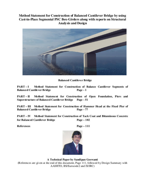
 SANDIPAN GOSWAMI