[go: up one dir, main page]

WO2022233683A1 - Ring halometer system and method for quantifying dysphotopsias - Google Patents

Ring halometer system and method for quantifying dysphotopsias Download PDF

Info

Publication number
WO2022233683A1
WO2022233683A1 PCT/EP2022/061265 EP2022061265W WO2022233683A1 WO 2022233683 A1 WO2022233683 A1 WO 2022233683A1 EP 2022061265 W EP2022061265 W EP 2022061265W WO 2022233683 A1 WO2022233683 A1 WO 2022233683A1
Authority
WO
WIPO (PCT)
Prior art keywords
light
ring
light source
patient
source
Prior art date
Legal status (The legal status is an assumption and is not a legal conclusion. Google has not performed a legal analysis and makes no representation as to the accuracy of the status listed.)
Ceased
Application number
PCT/EP2022/061265
Other languages
French (fr)
Inventor
Miguel Faria Ribeiro
Mark JENKINS SANCHEZ
Aixa ALARCON HEREDIA
Robert Rosen
Current Assignee (The listed assignees may be inaccurate. Google has not performed a legal analysis and makes no representation or warranty as to the accuracy of the list.)
AMO Groningen BV
Original Assignee
AMO Groningen BV
Priority date (The priority date is an assumption and is not a legal conclusion. Google has not performed a legal analysis and makes no representation as to the accuracy of the date listed.)
Filing date
Publication date
Application filed by AMO Groningen BV filed Critical AMO Groningen BV
Priority to EP22725883.7A priority Critical patent/EP4333685B1/en
Publication of WO2022233683A1 publication Critical patent/WO2022233683A1/en
Anticipated expiration legal-status Critical
Ceased legal-status Critical Current

Links

Classifications

    • AHUMAN NECESSITIES
    • A61MEDICAL OR VETERINARY SCIENCE; HYGIENE
    • A61BDIAGNOSIS; SURGERY; IDENTIFICATION
    • A61B3/00Apparatus for testing the eyes; Instruments for examining the eyes
    • A61B3/02Subjective types, i.e. testing apparatus requiring the active assistance of the patient
    • A61B3/024Subjective types, i.e. testing apparatus requiring the active assistance of the patient for determining the visual field, e.g. perimeter types
    • AHUMAN NECESSITIES
    • A61MEDICAL OR VETERINARY SCIENCE; HYGIENE
    • A61BDIAGNOSIS; SURGERY; IDENTIFICATION
    • A61B3/00Apparatus for testing the eyes; Instruments for examining the eyes
    • A61B3/0008Apparatus for testing the eyes; Instruments for examining the eyes provided with illuminating means
    • AHUMAN NECESSITIES
    • A61MEDICAL OR VETERINARY SCIENCE; HYGIENE
    • A61BDIAGNOSIS; SURGERY; IDENTIFICATION
    • A61B3/00Apparatus for testing the eyes; Instruments for examining the eyes
    • A61B3/02Subjective types, i.e. testing apparatus requiring the active assistance of the patient
    • A61B3/06Subjective types, i.e. testing apparatus requiring the active assistance of the patient for testing light sensitivity, e.g. adaptation; for testing colour vision
    • A61B3/063Subjective types, i.e. testing apparatus requiring the active assistance of the patient for testing light sensitivity, e.g. adaptation; for testing colour vision for testing light sensitivity, i.e. adaptation
    • AHUMAN NECESSITIES
    • A61MEDICAL OR VETERINARY SCIENCE; HYGIENE
    • A61FFILTERS IMPLANTABLE INTO BLOOD VESSELS; PROSTHESES; DEVICES PROVIDING PATENCY TO, OR PREVENTING COLLAPSING OF, TUBULAR STRUCTURES OF THE BODY, e.g. STENTS; ORTHOPAEDIC, NURSING OR CONTRACEPTIVE DEVICES; FOMENTATION; TREATMENT OR PROTECTION OF EYES OR EARS; BANDAGES, DRESSINGS OR ABSORBENT PADS; FIRST-AID KITS
    • A61F2/00Filters implantable into blood vessels; Prostheses, i.e. artificial substitutes or replacements for parts of the body; Appliances for connecting them with the body; Devices providing patency to, or preventing collapsing of, tubular structures of the body, e.g. stents
    • A61F2/02Prostheses implantable into the body
    • A61F2/14Eye parts, e.g. lenses or corneal implants; Artificial eyes
    • A61F2/16Intraocular lenses
    • HELECTRICITY
    • H05ELECTRIC TECHNIQUES NOT OTHERWISE PROVIDED FOR
    • H05BELECTRIC HEATING; ELECTRIC LIGHT SOURCES NOT OTHERWISE PROVIDED FOR; CIRCUIT ARRANGEMENTS FOR ELECTRIC LIGHT SOURCES, IN GENERAL
    • H05B45/00Circuit arrangements for operating light-emitting diodes [LED]
    • H05B45/10Controlling the intensity of the light
    • H05B45/12Controlling the intensity of the light using optical feedback

Definitions

  • the present disclosure relates to a ring halometer system and a method for quantifying dysphotopsias experienced by a patient having an intraocular lens implant.
  • An intraocular lens (IOL) implant is an artificial lens used to replace the natural lens of the eye that has developed cataracts.
  • IOL implants may be surgically placed by extracting the natural lens of the eye from the capsular bag of the eye and then inserting the IOL into the capsular bag.
  • IOL implants include monofocal lOLs, presbyopia correcting lOLs (e.g., multifocal or extended range of vision lOLs), accommodating lOLs that are configured to focus through engagement with the ciliary muscle in the eye, and toric lOLs.
  • Dysphotopsias are a common source of patients’ complaints after cataract and refractive surgery.
  • presbyopia correcting lOLs such as multifocal or extended range of vision lOLs, produce higher levels of dysphotopsias than monofocal lenses.
  • IOL explantation i.e. , secondary correction of an undesirable post-operative entopic phenomena
  • the present disclosure relates to various embodiments of a ring halometer system configured to quantify dysphotopsias in a patient, such as a patient that had cataract and refractive surgery to implant a presbyopia-correcting intraocular lens (IOL), corneal refractive surgery (e.g., LASIK or presby-LASIK), cornea reshaping (orthokeratology) to treat keratoconus, or in a patient wearing contact lenses.
  • the system includes a white screen and a first light source configured to emit a glare source (i.e. , an extended source of light) from the white screen.
  • the glare source is configured to form a veil of light visible to the patient due to the light scattered from an optical surface of the patient’s eye.
  • the system also includes a second light source (stimulus) configured to project a light ring concentric with the glare source emitted from the first light source on the white screen, and a controller coupled to the second light source configured to adjust a size of the light ring. Both the glare source and second light source are controlled by an electronic device.
  • the system may also include a user input device of the electronic device configured to record an indication from the patient when the size of the light ring is substantially equal to a size of the veil of light.
  • a memory device of the electronic device may include instructions which, when executed by a processor of the electronic device, cause the processor to determine a level of bothersomeness of the dysphotopsias experienced by the patient based on the size of the light ring.
  • the first light source may include a light-emitting diode (LED) and the second light source may be a projector.
  • the light ring may be a white ring or a color ring.
  • the first light source may include a spectrum filter to select a desired emitting spectrum of the glare source.
  • the system may also include a lux meter configured to automatically calibrate an illuminance of the light ring projected on the white screen by the second light source and/or to automatically calibrate an illuminance of the glare source emitted by the first light source.
  • the system may include a lux meter configured to check a calibration of an illuminance of the light ring projected on the white screen by the second light source and/or to check a calibration of an illuminance of the glare source emitted by the first light source.
  • the system may also include a controller configured to adjust the illuminance of the first light source.
  • the illuminance of the glare light source emitted by the first light source may be in a range from approximately 1 lux to approximately 100 lux, or more preferably from approximately 20 lux to approximately 80 lux.
  • a luminance of the light ring emitted by the second light source may be in a range from approximately 0.5 cd/m 2 to approximately 110 cd/m 2 or more preferably from 1 cd/m 2 to approximately 25 cd/m 2 .
  • the present disclosure also relates to various embodiments of a computer- implemented method of quantifying dysphotopsias in a patient after intraocular lens implantation.
  • the method includes emitting, from a first light source, a glare source surrounded by a white screen.
  • the glare source generates a veil of light in a retina of the patient.
  • the method also includes displaying, with a second light source, a light ring on the white screen concentric with the glare source, varying a diameter of the light ring displayed on the white screen, and receiving an indication, from the patient, in response to the diameter of the light ring being substantially equal to a diameter of the veil of light.
  • Varying of the diameter of the light ring may include increasing the diameter of the light ring and/or decreasing the diameter of the light ring.
  • the method may also include quantifying a level of bothersomeness of the dysphotopsias experienced by the patient based on the diameter of the light ring following receipt of the indication from the patient.
  • the method may also include measuring, with a light meter, an illuminance of the glare light source from the first light source and/or the illuminance of the light ring on the white screen, and adjusting the illuminance of the glare light source and/or the illuminance of the light ring.
  • the method may also include measuring, with a light meter, an illuminance of the glare light source from the first light source and/or the illuminance of the light ring on the white screen, and checking if a calibration of the illuminance of the glare light source and/or the illuminance of the light ring is correct.
  • a computer-implemented method of quantifying dysphotopsias in a patient includes viewing a glare light source emitted from a white screen, the glare light source generating a veil of light in the patient’s retina, viewing a light ring on the white screen concentric with the glare light source, and adjusting a size of the light ring until a diameter of the light ring is substantially equal to a diameter of the veil of light.
  • the method may also include entering a selection, with a user-input device, in response to the diameter of the light ring being substantially equal to the diameter of the veil of light.
  • Adjusting the size of the light ring may include increasing the diameter of the light ring until the light ring is visible from the veil of light and/or decreasing the diameter of the light ring until the light ring disappears into the veil of light.
  • One or more of the described features may be combined with one or more other described features to provide a workable system or method of quantifying dysphotopsias experienced by a patient, such as a patient that had cataract and refractive surgery to implant a presbyopia-correcting intraocular lens (IOL), corneal refractive surgery (e.g., LASIK or presby-LASIK), cornea reshaping (orthokeratology) to treat keratoconus, or in a patient wearing contact lenses.
  • IOL intraocular lens
  • corneal refractive surgery e.g., LASIK or presby-LASIK
  • cornea reshaping orthokeratology
  • FIGS. 1 A-1 C are schematic side views and a schematic front view, respectively, of a ring halometer system according to one embodiment of the present disclosure configured to enable performance of a test to quantify the impact of various dysphotopsias experienced by a patient, such as a patient with an intraocular lens (IOL) implant;
  • FIG. 2 depicts a veil of light and a light ring viewed by a patient implanted with an IOL
  • FIG. 3 depicts a veil of light and a light ring viewed by a patient implanted with an IOL during a test utilizing the ring halometer system of FIGS. 1A-1C, in which the illuminance of the light ring has been increased relative to the illuminance of the light ring depicted in FIG. 2;
  • FIG. 4A is a graph depicting the radius of the light ring, determined by a test utilizing the ring halometer system of FIGS. 1A-1 C, for each of five different lOLs and at two different illuminance levels of the first light source;
  • FIG. 4B is a graph depicting the level of bothersomeness of halos and starbursts in five different lOLs, as determined from clinical questionnaires of patients with these lOLs;
  • FIG. 5 is a flowchart illustrating tasks of a method of quantifying the impact of dysphotopsias in a patient with an IOL;
  • FIGS. 6A-6B depict a task of aligning a light ring with a glare source prior to performance of a test quantifying the impact of dysphotopsias in a patient.
  • the present disclosure relates to various embodiments of systems and methods for quantifying the impact (e.g., the level of bothersomeness) of various dysphotopsias (e.g., entopic phenomena, such as glare, halos, and/or starbursts) experienced by a patient.
  • various dysphotopsias e.g., entopic phenomena, such as glare, halos, and/or starbursts
  • the systems and methods of the present disclosure may be used to quantify the impact of various dysphotopsias in a patient, for example, after a refractive surgery that is expected to result in increased dysphotopsias, such as cataract and refractive surgery to implant a presbyopia-correcting intraocular lens (IOL), after corneal refractive surgery (e.g., LASIK or presby-LASIK), cornea reshaping (orthokeratology) to treat keratoconus, or in a patient wearing contact lenses (multifocal or other types).
  • a refractive surgery that is expected to result in increased dysphotopsias
  • cataract and refractive surgery to implant a presbyopia-correcting intraocular lens (IOL)
  • corneal refractive surgery e.g., LASIK or presby-LASIK
  • cornea reshaping orthokeratology
  • multifocal or other types multifocal or other types
  • the systems and methods of the present disclosure are configured to quantify the impact (e.g., the bothersomeness) of dysphotopsias in a patient with an IOL in an objective manner and more quickly than conventional perimetry techniques, such as the Rostock-Glare perimeter test and the Aston Glare perimeter test.
  • conventional perimetry techniques such as the Rostock-Glare perimeter test and the Aston Glare perimeter test.
  • FIG. 1A-1 C depict a ring halometer system 100 according to one embodiment of the present disclosure configured to quantify the impact (e.g., the level or degree of bothersomeness) of dysphotopsias (e.g., entopic phenomena, such as glare, halos, and/or starbursts) in a patient (e.g., dysphotopsias experienced by a patient after refractive surgery, such as cataract and refractive surgery to implant a presbyopia-correcting intraocular lens (IOL), after corneal refractive surgery, such as LASIK or presby-LASIK, after cornea reshaping (orthokeratology) to treat keratoconus, or in a patient wearing contact lenses).
  • dysphotopsias e.g., entopic phenomena, such as glare, halos, and/or starbursts
  • a patient after refractive surgery such as cataract and refractive surgery to implant a presby
  • the system 100 includes a screen 101 (e.g., a white screen, such as a white foamboard), a first light source 102 (e.g., at least one light-emitting diode (LED) with adjustable illuminance levels) configured to emit a glare light source (i.e., an extended source of light) from the screen 101, a second light source (stimulus) 103 (e.g., a projector, such as a short throw or an ultra-short throw projector) configured to project a light ring on a front surface of the screen 101 concentric (or substantially concentric) with the first light source 102, and an electronic device 104 electrically connected to the first light source 102 and the second light source 103.
  • the first light source 102 is at least partially housed in an opening 105 (e.g., a hole) in the screen 101
  • the second light source 103 and the electronic device 104 are provided on opposite sides of the screen 101.
  • the system 100 also includes a power source 106 coupled to the first light source 102.
  • the power source 106 is configured to adjust the illuminance of the first light source 102.
  • the first light source 102, the second light source 103, the electronic device 104 are connected to a power strip 107 (e.g., a surge protector) that is connected to an external power source.
  • the system 100 also includes a lux meter 108 (i.e.
  • a light meter configured to measure the illuminance of the first light source 102 and/or the second light source 103 in lux
  • the lux meter 108 is configured to measure the luminous flux per unit area of the first light source 102 and/or the second light source 103.
  • the illuminance of the first light source 102 and/or the second light source 103 measured by the lux meter 108 may be transmitted to the electronic device 104, and the electronic device 104 may be utilized to adjust (i.e., increase or decrease) the illuminance of the first light source 102 and/or the second light source 103.
  • the system 100 may include a controller separate from the electronic device 104 configured to adjust the illuminance of the first light source 102 and/or the second light source 103.
  • the illuminance of the glare source emitted by the first light source 102 may be adjusted in a range from approximately 1 lux to approximately 100 lux, or more preferably from approximately 20 lux to approximately 80 lux.
  • the luminance of the light ring emitted by the second light source 103 may be in a range from approximately 0.5 cd/m 2 to approximately 110 cd/m 2 or more preferably from 1 cd/m 2 to approximately 25 cd/m 2 .
  • the electronic device 104 may be a desktop computer, a laptop computer, a tablet computer, a wearable electronic device, or a “smart” cellular device.
  • the electronic device 104 includes a processor 109, computer-readable memory 110, a display 111 configured to display images, a network adapter 112 configured to communicate with other devices over a network, and one or more input/output (I/O) devices 113 (e.g., a keyboard and a mouse).
  • I/O input/output
  • the processor 109, the memory 110, the display 111, the network adapter 112, and the input/output (I/O) device(s) 113 communicate with one another over a system bus 114.
  • the memory device 110 may include persistent memory, such as NAND flash memory, for storing instructions.
  • One of the I/O devices 113 of the electronic device 104 is configured to enable the patient to adjust the diameter of the light ring displayed on the screen 101 by the second light source 103 (i.e. , the I/O device 113 enables the patient to increase and decrease the diameter of the light ring displayed on the screen 101).
  • the system 100 may include a controller separate from the electronic device 104 configured to enable the patient to adjust the diameter of the light ring displayed on the screen 101 by the second light source 103.
  • One of the I/O devices 113 of the electronic device 104 is configured to enable the patient to indicate (e.g., transmit a signal to the electronic device 104) when the diameter of the light ring on the screen 101 is equal or substantially equal to the diameter of a veil of light, which is generated when the light from the first light source 102 interacts with an optical surface of the patient’s eye (e.g., the IOL implanted in the patient), the significance of which is described below.
  • the first light source 102 may include a spectrum filter such that the light emitted from the second light source 102 has a desired emitting spectrum.
  • the light ring projected on the screen 101 by the second light source 103 may be at least one white ring and/or at least one color ring.
  • the second light source 103 is configured to project a light ring on the screen 101
  • the second light source 103 may be configured to project any other suitable shape on the screen 101, such as, for instance, an annular segment (e.g., a semi-circle or an arc) that can increase and decrease in size, a radial segment that can expand and contract in length, Gabor gratings of different contrast levels at different eccentricities and with different dimensions to conduct a perimetry-like contrast sensitivity test, white spots at different eccentricities to perform a perimetry-like test, and/or natural (real) scene images (e.g. a traffic scene or a street at night) to conduct a more functional assessment.
  • an annular segment e.g., a semi-circle or an arc
  • a radial segment that can expand and contract in length
  • Gabor gratings of different contrast levels at different eccentricities and with different dimensions to conduct a perimetry-like contrast sensitivity test white spots at different eccentricities to perform a peri
  • the ring halometer system 100 also includes a support 115 (e.g., a desk, table, or a cart) supporting screen 101, the first light source 102, the second light source 103, and the electronic device 104. Additionally, in the illustrated embodiment, the ring halometer system 100 includes a chair or other platform 116 to enable a patient (i.e. , a user having an IOL implant) to sit in front of the screen 101.
  • a support 115 e.g., a desk, table, or a cart
  • the ring halometer system 100 includes a chair or other platform 116 to enable a patient (i.e. , a user having an IOL implant) to sit in front of the screen 101.
  • the height of the support 115 and/or the platform 116 may be configured or adjusted such that the eyeline of the patient is aligned or substantially aligned with the first light source 102 (i.e., the height of the patient’s eyeline from the ground and the height of the first light source 102 from the ground are equal or substantially equal). Furthermore, in one or more embodiments, the height of the screen 101 and the first light source 102 positioned thereon may be adjusted depending, for instance, on the visual field to be measured and the distance to the patient.
  • the platform 116 (e.g., the chair) may be adjusted and positioned such that the patient’s eye is at a distance D of approximately 2.5 m from the screen 101 and the first light source 102, although in one or more embodiments the platform 116 (e.g., the chair) may be positioned such that the patient’s eye is at any other suitable distance D from the screen 101 and the first light source 102 and the size of the light ring projected by the second light source 103 may be adjusted accordingly.
  • the platform 116 (e.g., the chair) may be adjusted such that the patient’s eye is at a height H of approximately 125 cm from the floor such that the patient’s eye is vertically aligned with the first light source 102, although in one or more embodiments the platform 116 (e.g., the chair) may be such that the patient’s eye is at any other suitable height H from the floor depending on the height of the first light source 102 from the floor.
  • a patient e.g., a patient that had cataract and refractive surgery to implant a presbyopia-correcting intraocular lens (IOL), corneal refractive surgery (e.g., LASIK or presby-LASIK), cornea reshaping (orthokeratology) to treat keratoconus, or a patient wearing contact lenses) faces the screen 101 (e.g., by sitting in the chair 116) at a distance D and a height H such that the patient’s eye level is substantially aligned with the first light source 102 (e.g., the patient’s eye level is centered or substantially centered on the screen 101).
  • IOL intraocular lens
  • corneal refractive surgery e.g., LASIK or presby-LASIK
  • cornea reshaping orthokeratology
  • the first light source 102 emits a source of light L from the plane of the screen 101 , which functions as a glare source.
  • the light L emitted from the first light source 102 refracts, reflects, and/or passes through an optical surface of the patient’s eye (e.g., the IOL implanted in the patient’s eye), it generates a veil of light in the patient’s retina.
  • FIG. 2 depicts what the patient perceives during the test utilizing the ring halometer system 100.
  • the patient views the glare light source L emitted from the first light source 102, the veil of light V that is visible to the patient when the glare light source L emitted from the first light source 102 refracts, reflects, and/or passes through an optical surface of the patient’s eye (e.g., the IOL implanted in the patient’s eye), and the ring of light R projected by the second light source 103 that is concentric with the glare light L and the veil of light V.
  • the veil of light V includes a starburst pattern and a halo.
  • the diameter of the veil of light L corresponds or correlates with the impact (e.g., the level of bothersomeness) of various dysphotopsias (e.g., entopic phenomena, such as glare, halos, and/or starbursts) experienced by the patient due to, for example, the IOL.
  • various dysphotopsias e.g., entopic phenomena, such as glare, halos, and/or starbursts
  • the patient may then adjust the diameter of the light ring R projected on the screen 101 utilizing one of the I/O devices 113 of the electronic device 104 (e.g., a mouse and/or keyboard) or a separate controller coupled to the second light source 103.
  • the diameter of the light ring R is initially smaller than the diameter of the veil of light V, and the patient may increase the diameter of the light ring R until the light ring R becomes visible from behind the veil of light V (i.e. , the patient may use one of the I/O devices 113 of the electronic device 104 or the separate controller to increase the diameter of the light ring R until the diameter of the light ring R is equal or substantially equal to the diameter of the veil of light V).
  • the diameter of the light ring R is initially larger than the diameter of the veil of light V, and the patient may decrease the diameter of the light ring R until the light ring R disappears into the veil of light V (i.e., the patient may use one of the I/O devices 113 of the electronic device 104 or the separate controller to decrease the diameter of the light ring R until the diameter of the light ring R is equal or substantially equal to the diameter of the veil of light V).
  • the diameter of the light ring R is equal (or substantially equal) to the diameter of the veil of light V when the light ring R has the smallest diameter such that the light ring R is still discernible from the veil of light V.
  • the patient may stop adjusting the diameter of the light ring R and then indicate or otherwise signal (e.g., by making a selection with the one of the I/O devices 113 of the electronic device 104, such as the mouse) that the diameter of the light ring R is equal or substantially equal to the diameter of the veil of light V.
  • the illuminance of the first light source 102 and/or the second light source 103 may be adjusted and then the patient may repeat the tasks of adjusting the diameter of the light ring R and then indicating when the diameter of the light ring R is equal or substantially equally to the diameter of the veil of light V.
  • FIG. 3 depicts a veil of light V and a light ring R viewed by a patient (e.g., a patient that had cataract and refractive surgery to implant a presbyopia-correcting intraocular lens (IOL), corneal refractive surgery (e.g., LASIK or presby-LASIK), cornea reshaping (orthokeratology) to treat keratoconus, or in a patient wearing contact lenses) during a test utilizing the ring halometer system 100 of FIGS. 1A-1C, in which the illuminance of the light ring R has been increased relative to the illuminance of the light ring R depicted in FIG. 2 to evaluate the scatter level of the different structures in the dysphotopsia profile, as described in more detail below.
  • a patient e.g., a patient that had cataract and refractive surgery to implant a presbyopia-correcting intraocular lens (IOL), corneal refractive surgery (e.g
  • the electronic device 104 Based on the signal received from the patient indicating that the diameter of the light ring R is equal or substantially equal to the diameter of the veil of light V, the electronic device 104 is configured to determine (e.g., measure or calculate) the level of impact (e.g., the level of bothersomeness) of the dysphotopsias experienced by the patient.
  • the memory device 110 of the electronic device 104 stores instructions which, when executed by the processor 109, cause the processor 109 to calculate or determine the visual angle, Q (in degrees) subtended by the light ring R when the patient indicates that the diameter of the light ring R is equal or substantially equal to the diameter of the veil of light V perceived by the patient.
  • the memory device 110 of the electronic device 104 also stores instructions which, when executed by the processor 109, cause the processor 109 to calculate or determine the correspondent scatter level, Scatter, when the patient indicates that the diameter Dia of the light ring R is equal or substantially equal to the diameter of the veil of light V perceived by the patient.
  • the scatter level, Scatter is determined according to Equation (2) as follows:
  • Equation 2 Lv is the luminance of the light ring R (emitted from the second light source 103) and Ev is the illuminance of the glare source (emitted from the first light source 102) measured at the plane of the patient’s eye.
  • the scatter level Scatter calculated according to Equation 2 above can be used to evaluate the scatter levels created by an optical surface of the patient’s eye (e.g., an IOL).
  • the luminance Lv of the light ring R and/or the illuminance Ev of the glare source may be adjusted to different levels to measure the scatter level Scatter at one or more visual angles Q (i.e.
  • the scatter profile can be measured in vivo by adjusting the illuminance of the glare source and the luminance of the light ring).
  • the patient may repeatedly perform the task of adjusting the light ring R (e.g., increasing and/or decreasing the diameter of the light ring R) until the diameter Dia of the light ring R is equal (or substantially equal) to the diameter of the veil of light V, and the visual angle Q and scatter level Scatter determined according to Equations 1 and 2 above may be averaged across the tests.
  • the scatter level created by an IOL is described in van der Mooren, Marrie, et al. "Combining in vitro test methods for measuring light scatter in intraocular lenses.” Biomedical optics express 2.3 (2011 ): 505- 510, the entire content of which is incorporated herein by reference.
  • the memory device 110 of the electronic device 104 may store a lookup table associating different visual angles Q (or different ranges of visual angles Q) with different levels of bothersomeness of the dysphotopsias.
  • the level of bothersomeness may range from 1 (low level bothersomeness) to 5 (high level bothersomeness), although in one or more embodiments any other suitable scale may be utilized.
  • FIG. 4A is a graph depicting the visual angle Q (in degrees) subtended by the light ring R when the patient indicates that the diameter Dia of the light ring R is equal or substantially equal to the diameter of the veil of light V, as determined by a test utilizing the ring halometer system 100 of FIGS. 1A-1 C, for each of five different lOLs (labeled IOL1 , IOL2, IOL3, IOL4, and IOL5) at two different illuminance levels (45 lux and 78 lux) of the first light source 102 (which generates the glare source L emitted from the plane of the screen 101 and the veil of light V visible by the patient).
  • FIG. 4B is a graph depicting the level of bothersomeness, on a scale of 1 (least bothersome) to 5 (most bothersome), of halos and starbursts in each of the same five different lOLs (labeled IOL1 , IOL2, IOL3, IOL4, and IOL5), as determined from clinical questionnaires of patients with these lOLs.
  • FIGS. 4A and 4B there is a strong correlation between the level of bothersomeness as determined utilizing the ring halometer system 100 depicted in FIGS. 1A-1 C and the level of bothersomeness as indicated by the patients on the clinical questionnaires.
  • the table below lists the coefficient of determination (R 2 ) between the level of bothersomeness as determined by the clinical questionnaires and as determined by a test utilizing the ring halometer system 100 for each of two dysphotopsias (halos and starbursts) at two different levels of intensity (45 lux and 78 lux).
  • the table also shows a strong correlation (0.91 ) between the level of bothersomeness of halos as determined by the clinical questionnaires and the level of bothersomeness of the halos when measured utilizing the ring halometer system 100 at an illuminance of 78 lux, and a moderately strong correlation (0.74) between the level of bothersomeness of starbursts as determined by the clinical questionnaires and the level of bothersomeness of the starbursts when measured utilizing the ring halometer system 100 at an illuminance of 78 lux.
  • FIG. 5 is a flowchart illustrating tasks of a method 200 of quantifying the impact (e.g., the level of bothersomeness) of dysphotopsias (e.g., entopic phenomena, such as glare, halos, and/or starbursts) in a patient, such as a patient that had cataract and refractive surgery to implant a presbyopia-correcting intraocular lens (IOL), corneal refractive surgery (e.g., LASIK or presby-LASIK), cornea reshaping (orthokeratology) to treat keratoconus, or in a patient wearing contact lenses.
  • IOL intraocular lens
  • corneal refractive surgery e.g., LASIK or presby-LASIK
  • cornea reshaping orthokeratology
  • the method 200 includes a task 210 of calibrating the ring halometer system 100.
  • the task 210 of calibrating the ring halometer system 100 includes measuring the illuminance of the light emitted from the first light source 102 (e.g., the LED) and/or the illuminance of the light emitted from the second light source 103 (e.g., the projector) with the lux meter 108 (i.e.
  • the light meter and setting the illuminance of the light to a desired intensity, such as in a range from approximately 1 lux to approximately 100 lux, or more preferably from approximately 20 lux to approximately 80 lux (e.g., in a range from approximately 45 lux and approximately 78 lux).
  • the lux meter 108 may automatically calibrate the illuminance of the light ring R projected on the white screen 101 by the second light source 103 and/or automatically calibrate an illuminance of the glare source emitted by the first light source 102.
  • the lux meter 108 may be used to check (e.g., verify) a calibration of an illuminance of the light ring R projected on the white screen 101 by the second light source 103 and/or an illuminance of the glare source emitted by the first light source 102 is correct before the test is performed.
  • the luminance of the light ring emitted by the second light source 103 may be in a range from approximately 0.5 cd/m 2 to approximately 110 cd/m 2 or more preferably from 1 cd/m 2 to approximately 25 cd/m 2 .
  • the task 210 also includes aligning the light ring R projected from the second light source 103 (e.g., the projector) to be concentric or substantially concentric with the light emitted from the first light source 102.
  • the task 210 may include projecting a gray bar 119 (e.g., a gray rectangle) onto the screen 101 from the second light source 103 and confirming that a bright frame 120 does not appear around the gray bar 119 (as shown in FIG. 6A) or, if the bright frame 120 does appear around the gray bar 119 (as shown in FIG. 6B), adjusting the sharpness of the second light source 103 (e.g., the projector) to be zero (or substantially zero) such that the bright frame 120 is no longer visible.
  • a gray bar 119 e.g., a gray rectangle
  • the method 200 also includes a task 220 of measuring a pupil size of one of the patient’s eyes.
  • the task 220 of measuring the patient’s pupil size may utilize any suitable technique and/or device, such as, for example, a pupil gauge, the Rosenbaum (or equivalent) Card, a pupillometer (e.g., the Colvard pupillometer or the Procyon pupillometer), or any other device utilized by corneal topographers and tomographers.
  • the method 200 may not include the task 220 of measuring the pupil size of one of the patient’s eyes.
  • the method 200 also includes a task 230 of emitting, with the first light source 102 (e.g., at least one LED), a glare source of light from the plane of screen 101 (e.g., a white screen) viewed by a patient (e.g., a patient that had cataract and refractive surgery to implant a presbyopia-correcting intraocular lens (IOL), corneal refractive surgery (e.g., LASIK or presby-LASIK), cornea reshaping (orthokeratology) to treat keratoconus, or in a patient wearing contact lenses).
  • IOL intraocular lens
  • corneal refractive surgery e.g., LASIK or presby-LASIK
  • cornea reshaping orthokeratology
  • the illuminance of the first light source utilized in task 230 may be in a range from approximately 1 lux to approximately 100 lux, or more preferably from approximately 20 lux to approximately 80 lux (e.g., in a range from approximately 45 lux to approximately 78 lux).
  • the first light source 102 functions as a glare source, and when the light L emitted from the first light source 102 refracts, reflects, and/or passes through an optical surface of the patient’s eye (e.g., the IOL implanted in the patient’s eye), it generates a veil of light V in the patient’s retina (see FIGS. 2-3).
  • the method 200 also includes a task 240 of displaying, with the second light source 103, a light ring R on the screen.
  • the light ring R is concentric or substantially concentric with the light L emitted from the screen 101 by the first light source 102.
  • the light L emitted from the first light source 102 and the light ring R emitted from the second light source 103 may be centered (or substantially centered) on the screen 101.
  • the method 200 also includes a task 250 of adjusting the diameter of the light ring R projected on the screen 101 such that the diameter of the light ring R is equal or substantially equal to the diameter of the veil of light V. If the diameter of the light ring R is initially smaller than the diameter of the veil of light V, the task 250 may include increasing the diameter of the light ring R until the light ring R becomes visible to the patient from behind the veil of light V (i.e. , the task 250 may include increasing the diameter of the light ring R until the diameter of the light ring R is equal or substantially equal to the diameter of the veil of light V).
  • the task 250 may include decreasing the diameter of the light ring R until the light ring R disappears into the veil of light V such that the light ring R is no longer visible by the patient (i.e., the task 250 may include decreasing the diameter of the light ring R until the diameter of the light ring R is equal or substantially equal to the diameter of the veil of light V). In one or more embodiments, the task 250 may include adjusting the diameter of the light ring R until the light ring R has the smallest diameter such that the light ring R is still discernible from the veil of light V.
  • the task 250 of adjusting the diameter of the light ring R may be performed by the patient (e.g., the patient may operate an I/O device, such as a mouse and/or keyboard, to increase or decrease the diameter of the light ring R) or may be performed by a technician (e.g., a clinician) running the test.
  • the patient e.g., the patient may operate an I/O device, such as a mouse and/or keyboard, to increase or decrease the diameter of the light ring R
  • a technician e.g., a clinician
  • the method 200 also includes a task 260 of receiving a signal or other indication from the patient when the diameter of the light ring R is equal or substantially equal to the diameter of the veil of light V (e.g., a signal or other indication from the patient that the light ring R has decreased from its initial diameter to be visually obstructed by the veil of light V, or that the light ring R has sufficiently increased from its initial diameter to now be visible to the patient from behind the veil of light V).
  • a signal or other indication from the patient e.g., a signal or other indication from the patient that the light ring R has decreased from its initial diameter to be visually obstructed by the veil of light V, or that the light ring R has sufficiently increased from its initial diameter to now be visible to the patient from behind the veil of light V.
  • the method 200 includes a task 270 of determining (e.g., measuring or calculating) the level of impact (e.g., the level of bothersomeness) of the dysphotopsias on the patient (e.g., due to the IOL) based on the diameter of the light ring R and thus the diameter of the veil of light V.
  • the level of impact e.g., the level of bothersomeness
  • the task 270 includes determining the visual angle subtended by the light ring (according to Equation 1 above) and the correspondent scatter level (according to Equation 2), and then determining the corresponding level of bothersomeness of the dysphotopsias.
  • the task 270 may reference a database, such as a lookup table, associating different visual angles (or different ranges of visual angles) with different levels of bothersomeness of the dysphotopsias.
  • the level of bothersomeness determined in task 270 may range from 1 (low level bothersomeness) to 5 (high level bothersomeness), although in one or more embodiments any other suitable scale may be utilized. In this manner, the systems and methods of the present disclosure are configured to quantify the level of bothersomeness of dysphotopsias in a more objective and less invasive manner than conventional techniques.
  • the task 250 of adjusting the light ring e.g., increasing and/or decreasing the diameter of the light ring
  • the task 260 of receiving a signal or other indication from the patient when the diameter of the light ring R is equal or substantially equal to the diameter of the veil of light V may be repeatedly performed.
  • the task 270 of determining (e.g., measuring or calculating) the level of impact (e.g., the level of bothersomeness) of the dysphotopsias may be repeated performed each time tasks 250 and 260 are performed, and then the results may be averaged.
  • the method 200 described above may not be performed with the ring halometer system 100 described above.
  • the method 200 of quantifying dysphotopsias in a patient may be performed in the Aston Glare perimeter system or the Rostock Glare perimeter system.
  • processor refers broadly to any suitable device, logical block, module, circuit, or combination of elements for executing instructions.
  • each function is performed either by hardware configured, i.e. , hard-wired, to perform that function, or by more general purpose hardware, such as a CPU, configured to execute instructions stored in a non-transitory storage medium.
  • the processor may include any combination of hardware, firmware, and software, employed to process data or digital signals.
  • the processor 109 can include any conventional general purpose single- or multi-chip microprocessor such as a Pentium® processor, a MIPS® processor, a Power PC® processor, AMD® processor, ARM processor, or an ALPHA® processor.
  • the processor 109 can include any conventional special purpose microprocessor such as a digital signal processor.
  • Processor 109 can be implemented as a combination of computing devices, e.g., a combination of a DSP and a microprocessor, a plurality of microprocessors, one or more microprocessors in conjunction with a DSP core, or any other such configuration.
  • Computer readable memory 110 can refer to electronic circuitry that allows information, typically computer or digital data, to be stored and retrieved.
  • Computer readable memory 110 can refer to external devices or systems, for example, disk drives or solid state drives.
  • Computer readable memory 110 can also refer to fast semiconductor storage (chips), for example, Random Access Memory (RAM) or various forms of Read Only Memory (ROM), which are directly connected to the communication bus 114 or the processor 109.
  • RAM Random Access Memory
  • ROM Read Only Memory
  • Other types of memory include bubble memory and core memory.
  • Computer readable memory 110 can be physical hardware configured to store information in a non- transitory medium.
  • modules can refer to logic embodied in hardware and/or firmware, or to a collection of software instructions, possibly having entry and exit points, written in a programming language, such as, for example, C or C++.
  • a software module may be compiled and linked into an executable program, installed in a dynamically linked library, or may be written in an interpreted programming language such as, for example, BASIC, Perl, or Python. It will be appreciated that software modules may be callable from other modules or from themselves, and/or may be invoked in response to detected events or interrupts.
  • firmware such as an erasable programmable read-only memory (EPROM).
  • hardware modules may comprise connected logic units, such as gates and flip-flops, and/or may comprised programmable units, such as programmable gate arrays, application specific integrated circuits, and/or processors.
  • the modules described herein can be implemented as software modules, but also may be represented in hardware and/or firmware.
  • a module may be separately compiled, in other embodiments a module may represent a subset of instructions of a separately compiled program, and may not have an interface available to other logical program units.
  • code modules may be implemented and/or stored in any type of computer-readable medium or other computer storage device.
  • data (and/or metadata) input to the system, data generated by the system, and/or data used by the system can be stored in any type of computer data repository, such as a relational database and/or flat file system.
  • Any of the systems, methods, and processes described herein may include an interface configured to permit interaction with users, operators, other systems, components, programs, and so forth.
  • the terms “about” or “approximately”, when used in reference to a linear dimension mean within plus or minus one percent (1 %) of the value of the referenced linear dimension.

Landscapes

  • Health & Medical Sciences (AREA)
  • Life Sciences & Earth Sciences (AREA)
  • Ophthalmology & Optometry (AREA)
  • Animal Behavior & Ethology (AREA)
  • General Health & Medical Sciences (AREA)
  • Engineering & Computer Science (AREA)
  • Biomedical Technology (AREA)
  • Heart & Thoracic Surgery (AREA)
  • Veterinary Medicine (AREA)
  • Public Health (AREA)
  • Medical Informatics (AREA)
  • Physics & Mathematics (AREA)
  • Biophysics (AREA)
  • Molecular Biology (AREA)
  • Surgery (AREA)
  • Cardiology (AREA)
  • Oral & Maxillofacial Surgery (AREA)
  • Vascular Medicine (AREA)
  • Transplantation (AREA)
  • Prostheses (AREA)
  • Eye Examination Apparatus (AREA)

Abstract

A ring halometer system configured to quantify dysphotopsias in a patient. The system includes a white screen and a first light source configured to emit a glare source from the white screen. The glare source is configured to form a veil of light visible to the patient when the glare source interacts with an optical surface of the eye of the patient. The system also includes a second light source configured to project a light ring with varying luminance concentric with the glare light source on the white screen, and a controller coupled to the second light source configured to adjust a size of the light ring. The system may also include an electronic device configured to determine a level of bothersomeness of the dysphotopsias experienced by the patient based on the size of the light ring.

Description

RING HALOMETER SYSTEM AND METHOD FOR QUANTIFYING DYSPHOTOPSIAS
CROSS-REFERENCE TO RELATED APPLICATIONS
[0001] This application claims priority to U.S. Provisional Patent Application No. 63/184709, filed on May 5, 2021 , the entire contents of which are hereby incorporated by reference.
BACKGROUND
1. Field
[0002] The present disclosure relates to a ring halometer system and a method for quantifying dysphotopsias experienced by a patient having an intraocular lens implant.
2. Description of Related Art
[0003] An intraocular lens (IOL) implant is an artificial lens used to replace the natural lens of the eye that has developed cataracts. These IOL implants may be surgically placed by extracting the natural lens of the eye from the capsular bag of the eye and then inserting the IOL into the capsular bag. A variety of different types of IOL implants exist, including monofocal lOLs, presbyopia correcting lOLs (e.g., multifocal or extended range of vision lOLs), accommodating lOLs that are configured to focus through engagement with the ciliary muscle in the eye, and toric lOLs.
[0004] Dysphotopsias (e.g., unwanted entopic phenomena, such as glare, halos, and/or starbursts) are a common source of patients’ complaints after cataract and refractive surgery. In general, presbyopia correcting lOLs, such as multifocal or extended range of vision lOLs, produce higher levels of dysphotopsias than monofocal lenses. Although most patients tend to adapt over time, these entopic phenomena remain the leading cause for IOL explantation (i.e. , secondary correction of an undesirable post-operative entopic phenomena) in patients implanted with a presbyopia-correcting IOL.
[0005] Conventionally, the impact of dysphotopsias in the quality of life of IOL implant patients is assessed through clinical questionnaires to quantify the frequency and level of bothersome and/or severity of the halos, glares, and/or starbursts. However, these questionnaires are strongly subjective, highly variable between different studies and sites, and require large number of patients.
[0006] Although not commonly used in the clinical practice, some visual tests have been proposed to evaluate dysphotopsias in a more quantitative way. For example, the Rostock- Glare perimeter test and the Aston Glare perimeter test are able to measure different levels of dysphotopsias to distinguish between different intraocular lens technologies. However, these methodologies are based on a perimetry technique in which one location of the visual field is tested at a time until a map of the visual field is completed. Accordingly, these methodologies are quite time consuming, typically requiring approximately 10 minutes to complete. Additionally, during the time that the test is performed using these conventional methodologies, the patient must look at a screen with a very strong light source, concentrated in the test and without changing his position. These factors, combined with the average age of the cataract patients, limit the widespread adoption of these techniques in a clinical environment.
SUMMARY
[0007] The present disclosure relates to various embodiments of a ring halometer system configured to quantify dysphotopsias in a patient, such as a patient that had cataract and refractive surgery to implant a presbyopia-correcting intraocular lens (IOL), corneal refractive surgery (e.g., LASIK or presby-LASIK), cornea reshaping (orthokeratology) to treat keratoconus, or in a patient wearing contact lenses. In one embodiment, the system includes a white screen and a first light source configured to emit a glare source (i.e. , an extended source of light) from the white screen. The glare source is configured to form a veil of light visible to the patient due to the light scattered from an optical surface of the patient’s eye. The system also includes a second light source (stimulus) configured to project a light ring concentric with the glare source emitted from the first light source on the white screen, and a controller coupled to the second light source configured to adjust a size of the light ring. Both the glare source and second light source are controlled by an electronic device.
[0008] The system may also include a user input device of the electronic device configured to record an indication from the patient when the size of the light ring is substantially equal to a size of the veil of light.
[0009] A memory device of the electronic device may include instructions which, when executed by a processor of the electronic device, cause the processor to determine a level of bothersomeness of the dysphotopsias experienced by the patient based on the size of the light ring.
[0010] The first light source may include a light-emitting diode (LED) and the second light source may be a projector. The light ring may be a white ring or a color ring. The first light source may include a spectrum filter to select a desired emitting spectrum of the glare source.
[0011] The system may also include a lux meter configured to automatically calibrate an illuminance of the light ring projected on the white screen by the second light source and/or to automatically calibrate an illuminance of the glare source emitted by the first light source. [0012] The system may include a lux meter configured to check a calibration of an illuminance of the light ring projected on the white screen by the second light source and/or to check a calibration of an illuminance of the glare source emitted by the first light source. [0013] The system may also include a controller configured to adjust the illuminance of the first light source. The illuminance of the glare light source emitted by the first light source may be in a range from approximately 1 lux to approximately 100 lux, or more preferably from approximately 20 lux to approximately 80 lux.
[0014] A luminance of the light ring emitted by the second light source may be in a range from approximately 0.5 cd/m2 to approximately 110 cd/m2 or more preferably from 1 cd/m2 to approximately 25 cd/m2.
[0015] The present disclosure also relates to various embodiments of a computer- implemented method of quantifying dysphotopsias in a patient after intraocular lens implantation. In one embodiment, the method includes emitting, from a first light source, a glare source surrounded by a white screen. The glare source generates a veil of light in a retina of the patient. The method also includes displaying, with a second light source, a light ring on the white screen concentric with the glare source, varying a diameter of the light ring displayed on the white screen, and receiving an indication, from the patient, in response to the diameter of the light ring being substantially equal to a diameter of the veil of light. [0016] Varying of the diameter of the light ring may include increasing the diameter of the light ring and/or decreasing the diameter of the light ring.
[0017] The method may also include quantifying a level of bothersomeness of the dysphotopsias experienced by the patient based on the diameter of the light ring following receipt of the indication from the patient. [0018] The method may also include measuring, with a light meter, an illuminance of the glare light source from the first light source and/or the illuminance of the light ring on the white screen, and adjusting the illuminance of the glare light source and/or the illuminance of the light ring.
[0019] The method may also include measuring, with a light meter, an illuminance of the glare light source from the first light source and/or the illuminance of the light ring on the white screen, and checking if a calibration of the illuminance of the glare light source and/or the illuminance of the light ring is correct.
[0020] In another embodiment, a computer-implemented method of quantifying dysphotopsias in a patient includes viewing a glare light source emitted from a white screen, the glare light source generating a veil of light in the patient’s retina, viewing a light ring on the white screen concentric with the glare light source, and adjusting a size of the light ring until a diameter of the light ring is substantially equal to a diameter of the veil of light.
[0021] The method may also include entering a selection, with a user-input device, in response to the diameter of the light ring being substantially equal to the diameter of the veil of light.
[0022] Adjusting the size of the light ring may include increasing the diameter of the light ring until the light ring is visible from the veil of light and/or decreasing the diameter of the light ring until the light ring disappears into the veil of light.
[0023] This summary is provided to introduce a selection of features and concepts of embodiments of the present disclosure that are further described below in the detailed description. This summary is not intended to identify key or essential features of the claimed subject matter, nor is it intended to be used in limiting the scope of the claimed subject matter. One or more of the described features may be combined with one or more other described features to provide a workable system or method of quantifying dysphotopsias experienced by a patient, such as a patient that had cataract and refractive surgery to implant a presbyopia-correcting intraocular lens (IOL), corneal refractive surgery (e.g., LASIK or presby-LASIK), cornea reshaping (orthokeratology) to treat keratoconus, or in a patient wearing contact lenses.
BRIEF DESCRIPTION OF THE DRAWINGS [0024] The patent or application file contains at least one drawing executed in color.
Copies of this patent or patent application publication with color drawing(s) will be provided by the Office upon request and payment of the necessary fee.
[0025] The accompanying drawings, together with the specification, illustrate exemplary embodiments of the present disclosure, and, together with the description, serve to explain the principles of the present disclosure. The drawings are not necessarily drawn to scale. [0026] FIGS. 1 A-1 C are schematic side views and a schematic front view, respectively, of a ring halometer system according to one embodiment of the present disclosure configured to enable performance of a test to quantify the impact of various dysphotopsias experienced by a patient, such as a patient with an intraocular lens (IOL) implant; [0027] FIG. 2 depicts a veil of light and a light ring viewed by a patient implanted with an
IOL during a test utilizing the ring halometer system of FIGS. 1 A-1 C;
[0028] FIG. 3 depicts a veil of light and a light ring viewed by a patient implanted with an IOL during a test utilizing the ring halometer system of FIGS. 1A-1C, in which the illuminance of the light ring has been increased relative to the illuminance of the light ring depicted in FIG. 2; [0029] FIG. 4A is a graph depicting the radius of the light ring, determined by a test utilizing the ring halometer system of FIGS. 1A-1 C, for each of five different lOLs and at two different illuminance levels of the first light source;
[0030] FIG. 4B is a graph depicting the level of bothersomeness of halos and starbursts in five different lOLs, as determined from clinical questionnaires of patients with these lOLs; [0031] FIG. 5 is a flowchart illustrating tasks of a method of quantifying the impact of dysphotopsias in a patient with an IOL; and
[0032] FIGS. 6A-6B depict a task of aligning a light ring with a glare source prior to performance of a test quantifying the impact of dysphotopsias in a patient.
DETAILED DESCRIPTION
[0033] The present disclosure relates to various embodiments of systems and methods for quantifying the impact (e.g., the level of bothersomeness) of various dysphotopsias (e.g., entopic phenomena, such as glare, halos, and/or starbursts) experienced by a patient. The systems and methods of the present disclosure may be used to quantify the impact of various dysphotopsias in a patient, for example, after a refractive surgery that is expected to result in increased dysphotopsias, such as cataract and refractive surgery to implant a presbyopia-correcting intraocular lens (IOL), after corneal refractive surgery (e.g., LASIK or presby-LASIK), cornea reshaping (orthokeratology) to treat keratoconus, or in a patient wearing contact lenses (multifocal or other types). The systems and methods of the present disclosure are configured to quantify the impact (e.g., the bothersomeness) of dysphotopsias in a patient with an IOL in an objective manner and more quickly than conventional perimetry techniques, such as the Rostock-Glare perimeter test and the Aston Glare perimeter test. [0034] FIGS. 1A-1 C depict a ring halometer system 100 according to one embodiment of the present disclosure configured to quantify the impact (e.g., the level or degree of bothersomeness) of dysphotopsias (e.g., entopic phenomena, such as glare, halos, and/or starbursts) in a patient (e.g., dysphotopsias experienced by a patient after refractive surgery, such as cataract and refractive surgery to implant a presbyopia-correcting intraocular lens (IOL), after corneal refractive surgery, such as LASIK or presby-LASIK, after cornea reshaping (orthokeratology) to treat keratoconus, or in a patient wearing contact lenses). In the illustrated embodiment, the system 100 includes a screen 101 (e.g., a white screen, such as a white foamboard), a first light source 102 (e.g., at least one light-emitting diode (LED) with adjustable illuminance levels) configured to emit a glare light source (i.e., an extended source of light) from the screen 101, a second light source (stimulus) 103 (e.g., a projector, such as a short throw or an ultra-short throw projector) configured to project a light ring on a front surface of the screen 101 concentric (or substantially concentric) with the first light source 102, and an electronic device 104 electrically connected to the first light source 102 and the second light source 103. In the illustrated embodiment, the first light source 102 is at least partially housed in an opening 105 (e.g., a hole) in the screen 101, and the second light source 103 and the electronic device 104 are provided on opposite sides of the screen 101.
[0035] In the illustrated embodiment, the system 100 also includes a power source 106 coupled to the first light source 102. In one or more embodiments, the power source 106 is configured to adjust the illuminance of the first light source 102. Additionally, in the illustrated embodiment, the first light source 102, the second light source 103, the electronic device 104 are connected to a power strip 107 (e.g., a surge protector) that is connected to an external power source. [0036] In the illustrated embodiment, the system 100 also includes a lux meter 108 (i.e. , a light meter) configured to measure the illuminance of the first light source 102 and/or the second light source 103 in lux (i.e., the lux meter 108 is configured to measure the luminous flux per unit area of the first light source 102 and/or the second light source 103). The illuminance of the first light source 102 and/or the second light source 103 measured by the lux meter 108 may be transmitted to the electronic device 104, and the electronic device 104 may be utilized to adjust (i.e., increase or decrease) the illuminance of the first light source 102 and/or the second light source 103. In one or more embodiments, the system 100 may include a controller separate from the electronic device 104 configured to adjust the illuminance of the first light source 102 and/or the second light source 103. In one or more embodiments, the illuminance of the glare source emitted by the first light source 102 may be adjusted in a range from approximately 1 lux to approximately 100 lux, or more preferably from approximately 20 lux to approximately 80 lux. In one or more embodiments, the luminance of the light ring emitted by the second light source 103 may be in a range from approximately 0.5 cd/m2 to approximately 110 cd/m2 or more preferably from 1 cd/m2 to approximately 25 cd/m2.
[0037] The electronic device 104 may be a desktop computer, a laptop computer, a tablet computer, a wearable electronic device, or a “smart” cellular device. The electronic device 104 includes a processor 109, computer-readable memory 110, a display 111 configured to display images, a network adapter 112 configured to communicate with other devices over a network, and one or more input/output (I/O) devices 113 (e.g., a keyboard and a mouse). In the illustrated embodiment, the processor 109, the memory 110, the display 111, the network adapter 112, and the input/output (I/O) device(s) 113 communicate with one another over a system bus 114. In one or more embodiments, the memory device 110 may include persistent memory, such as NAND flash memory, for storing instructions. [0038] One of the I/O devices 113 of the electronic device 104 is configured to enable the patient to adjust the diameter of the light ring displayed on the screen 101 by the second light source 103 (i.e. , the I/O device 113 enables the patient to increase and decrease the diameter of the light ring displayed on the screen 101). In one or more embodiments, the system 100 may include a controller separate from the electronic device 104 configured to enable the patient to adjust the diameter of the light ring displayed on the screen 101 by the second light source 103.
[0039] One of the I/O devices 113 of the electronic device 104 is configured to enable the patient to indicate (e.g., transmit a signal to the electronic device 104) when the diameter of the light ring on the screen 101 is equal or substantially equal to the diameter of a veil of light, which is generated when the light from the first light source 102 interacts with an optical surface of the patient’s eye (e.g., the IOL implanted in the patient), the significance of which is described below.
[0040] In one or more embodiments, the first light source 102 may include a spectrum filter such that the light emitted from the second light source 102 has a desired emitting spectrum. The light ring projected on the screen 101 by the second light source 103 may be at least one white ring and/or at least one color ring. Although in the illustrated embodiment the second light source 103 is configured to project a light ring on the screen 101, in one or more embodiments the second light source 103 may be configured to project any other suitable shape on the screen 101, such as, for instance, an annular segment (e.g., a semi-circle or an arc) that can increase and decrease in size, a radial segment that can expand and contract in length, Gabor gratings of different contrast levels at different eccentricities and with different dimensions to conduct a perimetry-like contrast sensitivity test, white spots at different eccentricities to perform a perimetry-like test, and/or natural (real) scene images (e.g. a traffic scene or a street at night) to conduct a more functional assessment.
[0041] In one or more embodiments, the ring halometer system 100 also includes a support 115 (e.g., a desk, table, or a cart) supporting screen 101, the first light source 102, the second light source 103, and the electronic device 104. Additionally, in the illustrated embodiment, the ring halometer system 100 includes a chair or other platform 116 to enable a patient (i.e. , a user having an IOL implant) to sit in front of the screen 101. In one or more embodiments, the height of the support 115 and/or the platform 116 may be configured or adjusted such that the eyeline of the patient is aligned or substantially aligned with the first light source 102 (i.e., the height of the patient’s eyeline from the ground and the height of the first light source 102 from the ground are equal or substantially equal). Furthermore, in one or more embodiments, the height of the screen 101 and the first light source 102 positioned thereon may be adjusted depending, for instance, on the visual field to be measured and the distance to the patient. In one or more embodiments, the platform 116 (e.g., the chair) may be adjusted and positioned such that the patient’s eye is at a distance D of approximately 2.5 m from the screen 101 and the first light source 102, although in one or more embodiments the platform 116 (e.g., the chair) may be positioned such that the patient’s eye is at any other suitable distance D from the screen 101 and the first light source 102 and the size of the light ring projected by the second light source 103 may be adjusted accordingly. In one or more embodiments, the platform 116 (e.g., the chair) may be adjusted such that the patient’s eye is at a height H of approximately 125 cm from the floor such that the patient’s eye is vertically aligned with the first light source 102, although in one or more embodiments the platform 116 (e.g., the chair) may be such that the patient’s eye is at any other suitable height H from the floor depending on the height of the first light source 102 from the floor.
[0042] During performance of a test utilizing the ring halometer system 100, a patient (e.g., a patient that had cataract and refractive surgery to implant a presbyopia-correcting intraocular lens (IOL), corneal refractive surgery (e.g., LASIK or presby-LASIK), cornea reshaping (orthokeratology) to treat keratoconus, or a patient wearing contact lenses) faces the screen 101 (e.g., by sitting in the chair 116) at a distance D and a height H such that the patient’s eye level is substantially aligned with the first light source 102 (e.g., the patient’s eye level is centered or substantially centered on the screen 101). Once the patient is facing the screen 101 and the first light source 102 of the system 100 is turned on, the first light source 102 emits a source of light L from the plane of the screen 101 , which functions as a glare source. When the light L emitted from the first light source 102 refracts, reflects, and/or passes through an optical surface of the patient’s eye (e.g., the IOL implanted in the patient’s eye), it generates a veil of light in the patient’s retina. FIG. 2 depicts what the patient perceives during the test utilizing the ring halometer system 100. In the illustrated embodiment, the patient views the glare light source L emitted from the first light source 102, the veil of light V that is visible to the patient when the glare light source L emitted from the first light source 102 refracts, reflects, and/or passes through an optical surface of the patient’s eye (e.g., the IOL implanted in the patient’s eye), and the ring of light R projected by the second light source 103 that is concentric with the glare light L and the veil of light V. In the illustrated embodiment, the veil of light V includes a starburst pattern and a halo. As described in more detail below, the diameter of the veil of light L corresponds or correlates with the impact (e.g., the level of bothersomeness) of various dysphotopsias (e.g., entopic phenomena, such as glare, halos, and/or starbursts) experienced by the patient due to, for example, the IOL.
[0043] The patient may then adjust the diameter of the light ring R projected on the screen 101 utilizing one of the I/O devices 113 of the electronic device 104 (e.g., a mouse and/or keyboard) or a separate controller coupled to the second light source 103. In one embodiment, the diameter of the light ring R is initially smaller than the diameter of the veil of light V, and the patient may increase the diameter of the light ring R until the light ring R becomes visible from behind the veil of light V (i.e. , the patient may use one of the I/O devices 113 of the electronic device 104 or the separate controller to increase the diameter of the light ring R until the diameter of the light ring R is equal or substantially equal to the diameter of the veil of light V). In one embodiment, the diameter of the light ring R is initially larger than the diameter of the veil of light V, and the patient may decrease the diameter of the light ring R until the light ring R disappears into the veil of light V (i.e., the patient may use one of the I/O devices 113 of the electronic device 104 or the separate controller to decrease the diameter of the light ring R until the diameter of the light ring R is equal or substantially equal to the diameter of the veil of light V). In one or more embodiments, the diameter of the light ring R is equal (or substantially equal) to the diameter of the veil of light V when the light ring R has the smallest diameter such that the light ring R is still discernible from the veil of light V.
[0044] Once the diameter of the light ring R is equal or substantially equal to the diameter of the veil of light V (e.g., the light ring R appears from the veil of light V or disappears into the veil of light V), the patient may stop adjusting the diameter of the light ring R and then indicate or otherwise signal (e.g., by making a selection with the one of the I/O devices 113 of the electronic device 104, such as the mouse) that the diameter of the light ring R is equal or substantially equal to the diameter of the veil of light V.
[0045] In one or more embodiments, the illuminance of the first light source 102 and/or the second light source 103 may be adjusted and then the patient may repeat the tasks of adjusting the diameter of the light ring R and then indicating when the diameter of the light ring R is equal or substantially equally to the diameter of the veil of light V. FIG. 3 depicts a veil of light V and a light ring R viewed by a patient (e.g., a patient that had cataract and refractive surgery to implant a presbyopia-correcting intraocular lens (IOL), corneal refractive surgery (e.g., LASIK or presby-LASIK), cornea reshaping (orthokeratology) to treat keratoconus, or in a patient wearing contact lenses) during a test utilizing the ring halometer system 100 of FIGS. 1A-1C, in which the illuminance of the light ring R has been increased relative to the illuminance of the light ring R depicted in FIG. 2 to evaluate the scatter level of the different structures in the dysphotopsia profile, as described in more detail below.
[0046] Based on the signal received from the patient indicating that the diameter of the light ring R is equal or substantially equal to the diameter of the veil of light V, the electronic device 104 is configured to determine (e.g., measure or calculate) the level of impact (e.g., the level of bothersomeness) of the dysphotopsias experienced by the patient. In one or more embodiments, the memory device 110 of the electronic device 104 stores instructions which, when executed by the processor 109, cause the processor 109 to calculate or determine the visual angle, Q (in degrees) subtended by the light ring R when the patient indicates that the diameter of the light ring R is equal or substantially equal to the diameter of the veil of light V perceived by the patient. The visual angle, Q, is determined according to Equation (1) as follows: 0 = 2 * tan x( — ), (Equation 1) 2 D J where Dia is the diameter of the light ring, and D is the distance from the patient (e.g., the pupil or IOL of the patient) to the screen 101, as illustrated in FIGS. 1A and 1C. The memory device 110 of the electronic device 104 also stores instructions which, when executed by the processor 109, cause the processor 109 to calculate or determine the correspondent scatter level, Scatter, when the patient indicates that the diameter Dia of the light ring R is equal or substantially equal to the diameter of the veil of light V perceived by the patient. The scatter level, Scatter, is determined according to Equation (2) as follows:
Scatter
Figure imgf000017_0001
Figure imgf000017_0002
(Equation 2) where Lv is the luminance of the light ring R (emitted from the second light source 103) and Ev is the illuminance of the glare source (emitted from the first light source 102) measured at the plane of the patient’s eye. The scatter level Scatter calculated according to Equation 2 above can be used to evaluate the scatter levels created by an optical surface of the patient’s eye (e.g., an IOL). In one or more embodiments, the luminance Lv of the light ring R and/or the illuminance Ev of the glare source may be adjusted to different levels to measure the scatter level Scatter at one or more visual angles Q (i.e. , the scatter profile can be measured in vivo by adjusting the illuminance of the glare source and the luminance of the light ring). In one or more embodiments, the patient may repeatedly perform the task of adjusting the light ring R (e.g., increasing and/or decreasing the diameter of the light ring R) until the diameter Dia of the light ring R is equal (or substantially equal) to the diameter of the veil of light V, and the visual angle Q and scatter level Scatter determined according to Equations 1 and 2 above may be averaged across the tests. The scatter level created by an IOL is described in van der Mooren, Marrie, et al. "Combining in vitro test methods for measuring light scatter in intraocular lenses." Biomedical optics express 2.3 (2011 ): 505- 510, the entire content of which is incorporated herein by reference.
[0047] In one or more embodiments, the memory device 110 of the electronic device 104 may store a lookup table associating different visual angles Q (or different ranges of visual angles Q) with different levels of bothersomeness of the dysphotopsias. In one or more embodiments, the level of bothersomeness may range from 1 (low level bothersomeness) to 5 (high level bothersomeness), although in one or more embodiments any other suitable scale may be utilized.
[0048] FIG. 4A is a graph depicting the visual angle Q (in degrees) subtended by the light ring R when the patient indicates that the diameter Dia of the light ring R is equal or substantially equal to the diameter of the veil of light V, as determined by a test utilizing the ring halometer system 100 of FIGS. 1A-1 C, for each of five different lOLs (labeled IOL1 , IOL2, IOL3, IOL4, and IOL5) at two different illuminance levels (45 lux and 78 lux) of the first light source 102 (which generates the glare source L emitted from the plane of the screen 101 and the veil of light V visible by the patient).
[0049] FIG. 4B is a graph depicting the level of bothersomeness, on a scale of 1 (least bothersome) to 5 (most bothersome), of halos and starbursts in each of the same five different lOLs (labeled IOL1 , IOL2, IOL3, IOL4, and IOL5), as determined from clinical questionnaires of patients with these lOLs.
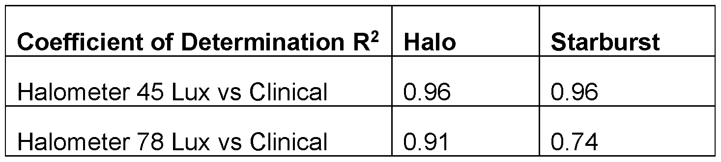
[0050] As illustrated in FIGS. 4A and 4B, there is a strong correlation between the level of bothersomeness as determined utilizing the ring halometer system 100 depicted in FIGS. 1A-1 C and the level of bothersomeness as indicated by the patients on the clinical questionnaires. The table below lists the coefficient of determination (R2) between the level of bothersomeness as determined by the clinical questionnaires and as determined by a test utilizing the ring halometer system 100 for each of two dysphotopsias (halos and starbursts) at two different levels of intensity (45 lux and 78 lux). As shown in the table below, there is a very strong correction (0.96) between the level of bothersomeness of halos and starbursts as determined by the clinical questionnaires and the level of bothersomeness of the halos and starbursts when measured utilizing the ring halometer system 100 at an illuminance of 45 lux. The table also shows a strong correlation (0.91 ) between the level of bothersomeness of halos as determined by the clinical questionnaires and the level of bothersomeness of the halos when measured utilizing the ring halometer system 100 at an illuminance of 78 lux, and a moderately strong correlation (0.74) between the level of bothersomeness of starbursts as determined by the clinical questionnaires and the level of bothersomeness of the starbursts when measured utilizing the ring halometer system 100 at an illuminance of 78 lux.
Figure imgf000019_0001
[0051] FIG. 5 is a flowchart illustrating tasks of a method 200 of quantifying the impact (e.g., the level of bothersomeness) of dysphotopsias (e.g., entopic phenomena, such as glare, halos, and/or starbursts) in a patient, such as a patient that had cataract and refractive surgery to implant a presbyopia-correcting intraocular lens (IOL), corneal refractive surgery (e.g., LASIK or presby-LASIK), cornea reshaping (orthokeratology) to treat keratoconus, or in a patient wearing contact lenses. In the illustrated embodiment, the method 200 includes a task 210 of calibrating the ring halometer system 100. In one or more embodiments, the task 210 of calibrating the ring halometer system 100 includes measuring the illuminance of the light emitted from the first light source 102 (e.g., the LED) and/or the illuminance of the light emitted from the second light source 103 (e.g., the projector) with the lux meter 108 (i.e. , the light meter) and setting the illuminance of the light to a desired intensity, such as in a range from approximately 1 lux to approximately 100 lux, or more preferably from approximately 20 lux to approximately 80 lux (e.g., in a range from approximately 45 lux and approximately 78 lux). In task 210, the lux meter 108 may automatically calibrate the illuminance of the light ring R projected on the white screen 101 by the second light source 103 and/or automatically calibrate an illuminance of the glare source emitted by the first light source 102. In one or more embodiments, in task 210, the lux meter 108 may be used to check (e.g., verify) a calibration of an illuminance of the light ring R projected on the white screen 101 by the second light source 103 and/or an illuminance of the glare source emitted by the first light source 102 is correct before the test is performed. In one or more embodiment, the luminance of the light ring emitted by the second light source 103 may be in a range from approximately 0.5 cd/m2 to approximately 110 cd/m2 or more preferably from 1 cd/m2 to approximately 25 cd/m2. In one or more embodiments, the task 210 also includes aligning the light ring R projected from the second light source 103 (e.g., the projector) to be concentric or substantially concentric with the light emitted from the first light source 102. FIGS. 6A-6B depict a task of aligning the light ring R projected from the second light source 103 with the glare light source L emitted from the first light source 102 according to one embodiment of the present disclosure includes adjusting the second light source 103 until the light ring R surrounds the first light source 102 on the screen 101 and four corners 117 of a pattern projected by the second light source 103 overlap corresponding alignment markers 118 (e.g., dots) on the screen 101. FIG. 6A depicts proper alignment between the light ring R projected by the second light source 103 and the first light source 102, and FIG. 6B depicts misalignment between the light ring R projected by the second light source 103 and the first light source 102. In one or more embodiments, the task 210 may include projecting a gray bar 119 (e.g., a gray rectangle) onto the screen 101 from the second light source 103 and confirming that a bright frame 120 does not appear around the gray bar 119 (as shown in FIG. 6A) or, if the bright frame 120 does appear around the gray bar 119 (as shown in FIG. 6B), adjusting the sharpness of the second light source 103 (e.g., the projector) to be zero (or substantially zero) such that the bright frame 120 is no longer visible.
[0052] In the illustrated embodiment, the method 200 also includes a task 220 of measuring a pupil size of one of the patient’s eyes. The task 220 of measuring the patient’s pupil size may utilize any suitable technique and/or device, such as, for example, a pupil gauge, the Rosenbaum (or equivalent) Card, a pupillometer (e.g., the Colvard pupillometer or the Procyon pupillometer), or any other device utilized by corneal topographers and tomographers. In one or more embodiments, the method 200 may not include the task 220 of measuring the pupil size of one of the patient’s eyes.
[0053] In the illustrated embodiment, the method 200 also includes a task 230 of emitting, with the first light source 102 (e.g., at least one LED), a glare source of light from the plane of screen 101 (e.g., a white screen) viewed by a patient (e.g., a patient that had cataract and refractive surgery to implant a presbyopia-correcting intraocular lens (IOL), corneal refractive surgery (e.g., LASIK or presby-LASIK), cornea reshaping (orthokeratology) to treat keratoconus, or in a patient wearing contact lenses). In one or more embodiments, the illuminance of the first light source utilized in task 230 may be in a range from approximately 1 lux to approximately 100 lux, or more preferably from approximately 20 lux to approximately 80 lux (e.g., in a range from approximately 45 lux to approximately 78 lux). As described above, the first light source 102 functions as a glare source, and when the light L emitted from the first light source 102 refracts, reflects, and/or passes through an optical surface of the patient’s eye (e.g., the IOL implanted in the patient’s eye), it generates a veil of light V in the patient’s retina (see FIGS. 2-3).
[0054] In the illustrated embodiment, the method 200 also includes a task 240 of displaying, with the second light source 103, a light ring R on the screen. In task 240, the light ring R is concentric or substantially concentric with the light L emitted from the screen 101 by the first light source 102. Additionally, in one or more embodiments, the light L emitted from the first light source 102 and the light ring R emitted from the second light source 103 may be centered (or substantially centered) on the screen 101.
[0055] The method 200 also includes a task 250 of adjusting the diameter of the light ring R projected on the screen 101 such that the diameter of the light ring R is equal or substantially equal to the diameter of the veil of light V. If the diameter of the light ring R is initially smaller than the diameter of the veil of light V, the task 250 may include increasing the diameter of the light ring R until the light ring R becomes visible to the patient from behind the veil of light V (i.e. , the task 250 may include increasing the diameter of the light ring R until the diameter of the light ring R is equal or substantially equal to the diameter of the veil of light V). If the diameter of the light ring R is initially larger than the diameter of the veil of light V, the task 250 may include decreasing the diameter of the light ring R until the light ring R disappears into the veil of light V such that the light ring R is no longer visible by the patient (i.e., the task 250 may include decreasing the diameter of the light ring R until the diameter of the light ring R is equal or substantially equal to the diameter of the veil of light V). In one or more embodiments, the task 250 may include adjusting the diameter of the light ring R until the light ring R has the smallest diameter such that the light ring R is still discernible from the veil of light V. The task 250 of adjusting the diameter of the light ring R may be performed by the patient (e.g., the patient may operate an I/O device, such as a mouse and/or keyboard, to increase or decrease the diameter of the light ring R) or may be performed by a technician (e.g., a clinician) running the test.
[0056] In the illustrated embodiment, the method 200 also includes a task 260 of receiving a signal or other indication from the patient when the diameter of the light ring R is equal or substantially equal to the diameter of the veil of light V (e.g., a signal or other indication from the patient that the light ring R has decreased from its initial diameter to be visually obstructed by the veil of light V, or that the light ring R has sufficiently increased from its initial diameter to now be visible to the patient from behind the veil of light V). [0057] In the illustrated embodiment, after the patient indicates that the diameter of the light ring R is equal or substantially equal to the diameter of the veil of light V in task 260, the method 200 includes a task 270 of determining (e.g., measuring or calculating) the level of impact (e.g., the level of bothersomeness) of the dysphotopsias on the patient (e.g., due to the IOL) based on the diameter of the light ring R and thus the diameter of the veil of light V. In one or more embodiments, the task 270 includes determining the visual angle subtended by the light ring (according to Equation 1 above) and the correspondent scatter level (according to Equation 2), and then determining the corresponding level of bothersomeness of the dysphotopsias. In one or more embodiments, the task 270 may reference a database, such as a lookup table, associating different visual angles (or different ranges of visual angles) with different levels of bothersomeness of the dysphotopsias. In one or more embodiments, the level of bothersomeness determined in task 270 may range from 1 (low level bothersomeness) to 5 (high level bothersomeness), although in one or more embodiments any other suitable scale may be utilized. In this manner, the systems and methods of the present disclosure are configured to quantify the level of bothersomeness of dysphotopsias in a more objective and less invasive manner than conventional techniques.
[0058] In one or more embodiments, the task 250 of adjusting the light ring (e.g., increasing and/or decreasing the diameter of the light ring) until the diameter of the light ring is equal (or substantially equal) to the diameter of the veil of light, and the task 260 of receiving a signal or other indication from the patient when the diameter of the light ring R is equal or substantially equal to the diameter of the veil of light V, may be repeatedly performed. Additionally, the task 270 of determining (e.g., measuring or calculating) the level of impact (e.g., the level of bothersomeness) of the dysphotopsias may be repeated performed each time tasks 250 and 260 are performed, and then the results may be averaged.
[0059] In one or more embodiments, the method 200 described above may not be performed with the ring halometer system 100 described above. In one or more embodiments, the method 200 of quantifying dysphotopsias in a patient may be performed in the Aston Glare perimeter system or the Rostock Glare perimeter system.
[0060] The above presents a description of the best mode contemplated of carrying out the concepts disclosed herein, and of the manner and process of making and using it, in such full, clear, concise, and exact terms as to enable any person skilled in the art to which it pertains to make and use the concepts described herein. The systems, methods and devices disclosed herein are, however, susceptible to modifications and alternate constructions from that discussed above which are fully equivalent. Consequently, it is not the intention to limit the scope of this disclosure to the particular embodiments disclosed. On the contrary, the intention is to cover modifications and alternate constructions coming within the spirit and scope of the present disclosure as generally expressed by the following claims, which particularly point out and distinctly claim the subject matter of the implementations described herein.
[0061] Each and every feature described herein, and each and every combination of two or more of such features, is included within the scope of the present invention provided that the features included in such a combination are not mutually inconsistent.
[0062] Although embodiments have been described and pictured in an example form with a certain degree of particularity, it should be understood that the present disclosure has been made by way of example, and that numerous changes in the details of construction and combination and arrangement of parts and steps may be made without departing from the spirit and scope of the disclosure as set forth in the claims hereinafter. [0063] As used herein, the term "processor" refers broadly to any suitable device, logical block, module, circuit, or combination of elements for executing instructions. In a processor, as used herein, each function is performed either by hardware configured, i.e. , hard-wired, to perform that function, or by more general purpose hardware, such as a CPU, configured to execute instructions stored in a non-transitory storage medium. The processor may include any combination of hardware, firmware, and software, employed to process data or digital signals. For example, the processor 109 can include any conventional general purpose single- or multi-chip microprocessor such as a Pentium® processor, a MIPS® processor, a Power PC® processor, AMD® processor, ARM processor, or an ALPHA® processor. In addition, the processor 109 can include any conventional special purpose microprocessor such as a digital signal processor. The various illustrative logical blocks, modules, and circuits described in connection with the embodiments disclosed herein can be implemented or performed with a general purpose processor or special purpose central processors (CPUs), a digital signal processor (DSP), graphics processors (GPUs), an application specific integrated circuit (ASIC), a field programmable gate array (FPGA), or other programmable logic device, discrete gate or transistor logic, discrete hardware components, or any combination thereof designed to perform the functions described herein. Processor 109 can be implemented as a combination of computing devices, e.g., a combination of a DSP and a microprocessor, a plurality of microprocessors, one or more microprocessors in conjunction with a DSP core, or any other such configuration. A processor may be fabricated on a single printed wiring board (PWB) or distributed over several interconnected PWBs. A processor may contain other processors; for example, a processor may include two processors, an FPGA and a CPU, interconnected on a PWB [0064] Computer readable memory 110 can refer to electronic circuitry that allows information, typically computer or digital data, to be stored and retrieved. Computer readable memory 110 can refer to external devices or systems, for example, disk drives or solid state drives. Computer readable memory 110 can also refer to fast semiconductor storage (chips), for example, Random Access Memory (RAM) or various forms of Read Only Memory (ROM), which are directly connected to the communication bus 114 or the processor 109. Other types of memory include bubble memory and core memory. Computer readable memory 110 can be physical hardware configured to store information in a non- transitory medium.
[0065] Methods and processes described herein may be embodied in, and partially or fully automated via, software code modules executed by one or more general and/or special purpose computers. The word "module" can refer to logic embodied in hardware and/or firmware, or to a collection of software instructions, possibly having entry and exit points, written in a programming language, such as, for example, C or C++. A software module may be compiled and linked into an executable program, installed in a dynamically linked library, or may be written in an interpreted programming language such as, for example, BASIC, Perl, or Python. It will be appreciated that software modules may be callable from other modules or from themselves, and/or may be invoked in response to detected events or interrupts. Software instructions may be embedded in firmware, such as an erasable programmable read-only memory (EPROM). It will be further appreciated that hardware modules may comprise connected logic units, such as gates and flip-flops, and/or may comprised programmable units, such as programmable gate arrays, application specific integrated circuits, and/or processors. The modules described herein can be implemented as software modules, but also may be represented in hardware and/or firmware. Moreover, although in some embodiments a module may be separately compiled, in other embodiments a module may represent a subset of instructions of a separately compiled program, and may not have an interface available to other logical program units.
[0066] In certain embodiments, code modules may be implemented and/or stored in any type of computer-readable medium or other computer storage device. In some systems, data (and/or metadata) input to the system, data generated by the system, and/or data used by the system can be stored in any type of computer data repository, such as a relational database and/or flat file system. Any of the systems, methods, and processes described herein may include an interface configured to permit interaction with users, operators, other systems, components, programs, and so forth.
[0067] As used herein, the terms "about" or "approximately", when used in reference to a lux value of illuminance, mean within plus or minus 0.5 lux of the referenced illuminance. As used herein, the terms "about" or "approximately", when used in reference to a linear dimension (e.g., length, width, thickness, distance, etc.) mean within plus or minus one percent (1 %) of the value of the referenced linear dimension.

Claims

WHAT IS CLAIMED IS:
1 . A ring halometer system configured to quantify dysphotopsias in a patient, the system comprising: a white screen; a first light source configured to emit a glare source from a plane of the white screen, the glare source configured to form a veil of light visible to the patient when the glare source interacts with an optical surface of the eye of the patient; a second light source configured to project a light ring concentric with the first light source on the white screen; and a controller coupled to the second light source, the controller configured to adjust a size of the light ring.
2. The system of claim 1 , further comprising an electronic device coupled to the first light source and the second light source.
3. The system of claim 2, further comprising a user input device of the electronic device configured to record an indication from the patient when the size of the light ring is substantially equal to a size of the veil of light.
4. The system of claim 3, wherein a memory device of the electronic device comprises instructions which, when executed by a processor of the electronic device, cause the processor to determine a level of bothersomeness of the dysphotopsias experienced by the patient based on the size of the light ring.
5. The system of claim 1 , wherein the first light source comprises a light-emitting diode (LED).
6. The system of claim 1 , wherein the second light source is a projector.
7. The system of claim 1 , further comprising a lux meter configured to automatically calibrate an illuminance of the light ring projected on the white screen by the second light source.
8. The system of claim 1 , further comprising a lux meter configured to automatically calibrate an illuminance of the glare source emitted by the first light source.
9. The system of claim 1 , further comprising a lux meter configured to check a calibration of an illuminance of the light ring projected on the white screen by the second light source.
10. The system of claim 1 , further comprising a lux meter configured to check a calibration of an illuminance of the glare source emitted by the first light source.
11. The system of claim 10, further comprising a controller configured to adjust the illuminance of the glare source.
12. The system of claim 1 , wherein an illuminance of the glare source emitted by the first light source is in a range from approximately 1 lux to approximately 100 lux.
13. The system of claim 1 , wherein a luminance of the light ring emitted by the second light source is in a range from approximately .5 cd/m2 to approximately 110 cd/m2
14. The system of claim 1 , light ring is a white ring.
15. The system of claim 1 , light ring is a color ring.
16. The system of claim 1 , wherein the first light source has a spectrum filter to select a desired emitting spectrum of the glare source.
17. The system of claim 1 , wherein the second light source is configured to project at least one real scene image on the screen.
18. The system of claim 17, wherein the first light source comprises a plurality of light sources configured to emit light from light source areas of the natural scene image.
19. A computer-implemented method of quantifying dysphotopsias in a patient, the method comprising: emitting, from a first light source, a glare source generating a veil of light in a retina of the patient; displaying, with a second light source, a light ring on the white screen concentric with the glare source; varying a diameter of the light ring displayed on the white screen; receiving an indication, from the patient, in response to the diameter of the light ring being substantially equal to a diameter of the veil of light.
20. The method of claim 19, wherein the varying of the diameter of the light ring comprises increasing the diameter of the light ring.
21. The method of claim 19, wherein the varying of the diameter of the light ring comprises decreasing the diameter of the light ring.
22. The method of claim 19, further comprising quantifying a level of bothersomeness of the dysphotopsias experienced by the patient based on the diameter of the light ring following the receiving of the indication from the patient.
23. The method of claim 19, further comprising: measuring, with a light meter, an illuminance of the glare light source from the first light source; and adjusting the illuminance of the glare light source.
24. The method of claim 19, further comprising: measuring, with a light meter, an illuminance of the light ring on the white screen; and adjusting the illuminance of the light ring.
25. The method of claim 19, further comprising: measuring, with a light meter, an illuminance of the glare source from the first light source; and checking if a calibration of the illuminance of the glare source is correct.
26. The method of claim 19, further comprising: measuring, with a light meter, an illuminance of the light ring on the white screen; and checking if a calibration of the illuminance of the light ring is correct.
27. A computer-implemented method of quantifying dysphotopsias in a patient, the method comprising: viewing a glare light source emitted from a white screen, the glare light source generating a veil of light in the patient’s retina; viewing a light ring on the white screen concentric with the glare light source; and adjusting a size of the light ring until a diameter of the light ring is substantially equal to a diameter of the veil of light.
28. The method of claim 27, further comprising entering a selection, with a user-input device, in response to the diameter of the light ring being substantially equal to the diameter of the veil of light.
29. The method of claim 27, wherein the adjusting the size comprises increasing the diameter of the light ring until the light ring is visible from the veil of light.
30. The method of claim 27, wherein the adjusting the size comprises decreasing the diameter of the light ring until the light ring disappears into the veil of light.
PCT/EP2022/061265 2021-05-05 2022-04-27 Ring halometer system and method for quantifying dysphotopsias Ceased WO2022233683A1 (en)

Priority Applications (1)

Application Number Priority Date Filing Date Title
EP22725883.7A EP4333685B1 (en) 2021-05-05 2022-04-27 Ring halometer system and method for quantifying dysphotopsias

Applications Claiming Priority (2)

Application Number Priority Date Filing Date Title
US202163184709P 2021-05-05 2021-05-05
US63/184,709 2021-05-05

Publications (1)

Publication Number Publication Date
WO2022233683A1 true WO2022233683A1 (en) 2022-11-10

Family

ID=81850089

Family Applications (1)

Application Number Title Priority Date Filing Date
PCT/EP2022/061265 Ceased WO2022233683A1 (en) 2021-05-05 2022-04-27 Ring halometer system and method for quantifying dysphotopsias

Country Status (3)

Country Link
US (1) US12478248B2 (en)
EP (1) EP4333685B1 (en)
WO (1) WO2022233683A1 (en)

Citations (2)

* Cited by examiner, † Cited by third party
Publication number Priority date Publication date Assignee Title
US20140081395A1 (en) * 2010-11-30 2014-03-20 Amo Groningen B.V. Method for designing, evaluating and optimizing ophthalmic lenses and laser vision correction
US20200315848A1 (en) * 2019-04-05 2020-10-08 Amo Groningen B.V. Systems and methods for multiple layer intraocular lens and using refractive index writing

Family Cites Families (400)

* Cited by examiner, † Cited by third party
Publication number Priority date Publication date Assignee Title
US2077092A (en) 1936-01-13 1937-04-13 Broder Simon Ophthalmic lens
GB1054972A (en) 1963-02-22
US3305294A (en) 1964-12-03 1967-02-21 Optical Res & Dev Corp Two-element variable-power spherical lens
US3735685A (en) 1971-05-07 1973-05-29 Polaroid Corp Reflective imaging apparatus
US4093361A (en) 1971-11-15 1978-06-06 Precision Cosmet Co., Inc. Composite prosthetic polymeric devices
US4056311A (en) 1973-08-16 1977-11-01 American Optical Corporation Progressive power ophthalmic lens having a plurality of viewing zones with non-discontinuous variations therebetween
US4010496A (en) 1975-10-01 1977-03-08 Neefe Charles W Bifocal lens which positions within the anterior chamber
US4077071A (en) 1976-03-15 1978-03-07 Freeman Jerre M Neutral buoyancy intraocular lens device
US4134160A (en) 1977-03-16 1979-01-16 Bayers Jon Herbert Intraocular lens
US4162122A (en) 1977-09-14 1979-07-24 Cohen Allen L Zonal bifocal contact lens
US4210391A (en) 1977-09-14 1980-07-01 Cohen Allen L Multifocal zone plate
US4174543A (en) 1978-06-01 1979-11-20 Kelman Charles D Intraocular lenses
US4338005A (en) 1978-12-18 1982-07-06 Cohen Allen L Multifocal phase place
US4340283A (en) 1978-12-18 1982-07-20 Cohen Allen L Phase shift multifocal zone plate
US4254509A (en) 1979-04-09 1981-03-10 Tennant Jerald L Accommodating intraocular implant
US4254510A (en) 1979-06-18 1981-03-10 Tennant Jerald L Implant lens with biarcuate fixation
US4316293A (en) 1979-08-27 1982-02-23 Bayers Jon Herbert Flexible intraocular lens
US4319564A (en) 1980-01-03 1982-03-16 Karickhoff John R Instrument for measurement of the diameter of the anterior chamber of the eye
US4249272A (en) 1980-03-05 1981-02-10 Stanley Poler Intraocular lens
USRE32525F1 (en) 1980-04-01 1989-05-09 Universal intraocular lens and a method of measuring an eye chamber size
JPS5719709A (en) 1980-07-11 1982-02-02 Nippon Kogaku Kk <Nikon> Zoom lens
US4377873A (en) 1980-10-30 1983-03-29 Reichert Jr Henry L Intraocular lens
US4480340A (en) 1981-02-18 1984-11-06 Shepard Dennis D Intraocular lens with resilient support means
DE8107675U1 (en) 1981-03-03 1981-07-30 Porsche Design Produkte Vertriebsgesellschaft mbH, 5020 Salzburg "TRIANGLE RULER"
US4370760A (en) 1981-03-25 1983-02-01 Kelman Charles D Anterior chamber intraocular lens
EP0064812B1 (en) 1981-04-29 1985-08-14 Pilkington P.E. Limited Artificial eye lenses
DE3119002A1 (en) 1981-05-13 1982-12-02 INPROHOLD Establishment, 9490 Vaduz REAR CHAMBER IMPLANTATION LENS
US4403353A (en) 1981-06-25 1983-09-13 Tennant Jerald L Anterior chamber implant lens
US4402579A (en) 1981-07-29 1983-09-06 Lynell Medical Technology Inc. Contact-lens construction
US4446581A (en) 1981-09-02 1984-05-08 Blake L W Intraocular lens with free-ended sizing prong
US4409691A (en) 1981-11-02 1983-10-18 Levy Chauncey F Focussable intraocular lens
US4404694A (en) 1982-03-18 1983-09-20 Kelman Charles D Intraocular lens
US4504982A (en) 1982-08-05 1985-03-19 Optical Radiation Corporation Aspheric intraocular lens
EP0109753B1 (en) 1982-10-27 1988-07-27 Pilkington Plc Bifocal contact lens comprising a plurality of concentric zones
US4500382A (en) 1983-06-10 1985-02-19 Transilwrap Company, Inc. Method of manufacture of resin film precision biomedical article
US4556998A (en) 1983-08-04 1985-12-10 Siepser Steven B Artificial intraocular lenses and method for their surgical implantation
DE3431224A1 (en) 1983-08-04 1986-03-06 Steven B Siepser Artificial intraocular lens
US4551864A (en) 1983-08-18 1985-11-12 Iolab Corporation Anterior chamber lens
US4560383A (en) 1983-10-27 1985-12-24 Leiske Larry G Anterior chamber intraocular lens
US5207668A (en) 1983-11-17 1993-05-04 Visx Incorporated Method for opthalmological surgery
US5219343A (en) 1983-11-17 1993-06-15 Visx Incorporated Apparatus for performing ophthalmogolical surgery
US4773414A (en) 1983-11-17 1988-09-27 Lri L.P. Method of laser-sculpture of the optically used portion of the cornea
US4732148A (en) 1983-11-17 1988-03-22 Lri L.P. Method for performing ophthalmic laser surgery
US4770172A (en) 1983-11-17 1988-09-13 Lri L.P. Method of laser-sculpture of the optically used portion of the cornea
US4665913A (en) 1983-11-17 1987-05-19 Lri L.P. Method for ophthalmological surgery
US4687484A (en) 1983-12-12 1987-08-18 Kaplan Linda J Anterior chamber intraocular lens
US5108388B1 (en) 1983-12-15 2000-09-19 Visx Inc Laser surgery method
GB8404817D0 (en) 1984-02-23 1984-03-28 Pilkington Perkin Elmer Ltd Ophthalmic lenses
US4605409A (en) 1984-05-21 1986-08-12 Kelman Charles D Intraocular lens with miniature optic having expandable and contractible glare-reducing means
US4629460A (en) 1984-06-25 1986-12-16 Dyer Robert L Intraocular lens
US4787904A (en) 1984-07-06 1988-11-29 Severin Sanford L Hydrophillic intraocular lens
US4629462A (en) 1984-07-13 1986-12-16 Feaster Fred T Intraocular lens with coiled haptics
SU1311063A1 (en) 1984-09-27 1988-01-30 Московский научно-исследовательский институт микрохирургии глаза Eye artificial lens
DE3439551A1 (en) 1984-10-29 1986-04-30 Inprohold Establishment, Vaduz ONE-PIECE IMPLANTING LENS
FI79619C (en) 1984-12-31 1990-01-10 Antti Vannas Intraocular lens
US4669466A (en) 1985-01-16 1987-06-02 Lri L.P. Method and apparatus for analysis and correction of abnormal refractive errors of the eye
US4787903A (en) 1985-07-24 1988-11-29 Grendahl Dennis T Intraocular lens
US4781717A (en) 1985-07-24 1988-11-01 Grendahl Dennis T Intraocular lens
US4676791A (en) 1985-08-01 1987-06-30 Surgidev Corporation Intraocular lens and method for making same
US4687485A (en) 1985-08-23 1987-08-18 Barnes-Hind, Inc. Intraocular lens with leg means having compressible regions and/or color
US4681102A (en) 1985-09-11 1987-07-21 Bartell Michael T Apparatus and method for insertion of an intra-ocular lens
US4834751A (en) 1985-12-04 1989-05-30 Allergan, Inc. Staking ring for soft IOL
CA1283252C (en) 1985-12-09 1991-04-23 Albert C. Ting Haptic to optic attachment for a soft iol
CH671329A5 (en) 1986-01-21 1989-08-31 Interzeag Ag
US4725277A (en) 1986-05-14 1988-02-16 Precision-Cosmet Co., Inc. Intraocular lens with tapered haptics
US5121979A (en) 1986-05-14 1992-06-16 Cohen Allen L Diffractive multifocal optical device
US5144483A (en) 1986-05-14 1992-09-01 Cohen Allen L Diffractive multifocal optical device
US4676792A (en) 1986-08-26 1987-06-30 Donald Praeger Method and artificial intraocular lens device for the phakic treatment of myopia
US5270744A (en) 1987-06-01 1993-12-14 Valdemar Portney Multifocal ophthalmic lens
US4898461A (en) 1987-06-01 1990-02-06 Valdemar Portney Multifocal ophthalmic lens
US5225858A (en) 1987-06-01 1993-07-06 Valdemar Portney Multifocal ophthalmic lens
US4828558A (en) 1987-07-28 1989-05-09 Kelman Charles D Laminate optic with interior Fresnel lens
US5163934A (en) 1987-08-05 1992-11-17 Visx, Incorporated Photorefractive keratectomy
US4798609A (en) 1987-08-24 1989-01-17 Grendahl Dennis T Radially segmented zone of focus artificial lens
US4778462A (en) 1987-08-24 1988-10-18 Grendahl Dennis T Multiple element zone of focus artificial lens
US4798608A (en) 1987-08-24 1989-01-17 Grendahl Dennis T Laminated zone of focus artificial lens
US4795462A (en) 1987-08-24 1989-01-03 Grendahl Dennis T Cylindrically segmented zone of focus artificial lens
US4834748A (en) 1987-09-29 1989-05-30 Allergan, Inc. Method and apparatus for removing corneal tissue
US5047052A (en) 1987-11-06 1991-09-10 Seymour Dubroff Anterior chamber intraocular lens with four point fixation
US4863539A (en) 1987-11-06 1989-09-05 Optical Radiation Corporation Haptic attachment for intraocular lenses
US5056908A (en) 1987-11-12 1991-10-15 Cohen Allen L Optic zone phase channels
US5054905A (en) 1987-11-12 1991-10-08 Cohen Allen L Progressive intensity phase bifocal
US4764930A (en) 1988-01-27 1988-08-16 Intelligent Surgical Lasers Multiwavelength laser source
FR2631228B1 (en) 1988-05-11 1990-08-10 Domilens Laboratoires INTRA-EYE IMPLANT OF PREVIOUS CHAMBER
US4932970A (en) 1988-05-17 1990-06-12 Allergan, Inc. Ophthalmic lens
FR2631713B1 (en) 1988-05-19 1990-08-31 Essilor Int DIFFRACTIVE LENS WITH MIXED PROFILE
DE3854966T2 (en) 1988-07-20 1996-05-30 Allen L Cohen Multifocal, diffractive optical device
US4995714A (en) 1988-08-26 1991-02-26 Cohen Allen L Multifocal optical device with novel phase zone plate and method for making
FR2642855B1 (en) 1989-02-06 1991-05-17 Essilor Int OPTICAL LENS FOR THE CORRECTION OF ASTIGMATISM
US5121980A (en) 1989-04-19 1992-06-16 Cohen Allen L Small aperture multifocal
US4997442A (en) 1989-05-04 1991-03-05 Alcon Laboratories, Inc. Bicomposite intraocular lenses
US5042938A (en) 1989-05-09 1991-08-27 Kabushiki Kaisha Topcon Apparatus for measuring length of visual line length, depth of anterior chamber, thickness of crystal lens, etc.
US5078742A (en) 1989-08-28 1992-01-07 Elie Dahan Posterior chamber lens implant
US5019097A (en) 1989-11-22 1991-05-28 Allergan, Inc. Corneal onlay lenses and methods for attaching same
US5089023A (en) 1990-03-22 1992-02-18 Massachusetts Institute Of Technology Diffractive/refractive lens implant
US5096285A (en) 1990-05-14 1992-03-17 Iolab Corporation Multifocal multizone diffractive ophthalmic lenses
JP2526717B2 (en) 1990-06-21 1996-08-21 日本電気株式会社 Laser processing equipment
US5147397A (en) 1990-07-03 1992-09-15 Allergan, Inc. Intraocular lens and method for making same
US5117306A (en) 1990-07-17 1992-05-26 Cohen Allen L Diffraction bifocal with adjusted chromaticity
US5120120A (en) 1990-07-27 1992-06-09 Cohen Allen L Multifocal optical device with spurious order suppression and method for manufacture of same
US5229797A (en) 1990-08-08 1993-07-20 Minnesota Mining And Manufacturing Company Multifocal diffractive ophthalmic lenses
US5173723A (en) 1990-10-02 1992-12-22 Volk Donald A Aspheric ophthalmic accommodating lens design for intraocular lens and contact lens
US5066301A (en) 1990-10-09 1991-11-19 Wiley Robert G Variable focus lens
US5258025A (en) 1990-11-21 1993-11-02 Fedorov Svjatoslav N Corrective intraocular lens
US5217491A (en) 1990-12-27 1993-06-08 American Cyanamid Company Composite intraocular lens
US5133749A (en) 1991-05-13 1992-07-28 Nordan Lee T Centrating haptics
US5106180A (en) 1991-05-30 1992-04-21 Robert Marie Multifocal ophthalmic lens
US5147395A (en) 1991-07-16 1992-09-15 Allergan Inc. Small incision endocapsulator IOL
US5570143A (en) 1991-08-09 1996-10-29 Capricornia Contact Lens Pty. Ltd. Toric lens with axis mislocation latitude
DE69232283T2 (en) 1991-10-09 2002-05-23 Seiko Epson Corp., Tokio/Tokyo Lens for glasses.
FR2682761B1 (en) 1991-10-18 1994-05-06 Onera METHOD AND DEVICE FOR ANALYZING A LIGHT WAVE SURFACE.
JPH0697244B2 (en) 1991-10-23 1994-11-30 郵政省通信総合研究所長 Method and device for measuring impedance of sample surface
US5203790A (en) 1991-11-12 1993-04-20 Henry H. McDonald Foldable plastic optical lens with reduced thickness light blocking segments, and anchoring means
US5184405A (en) 1991-12-18 1993-02-09 Jonathan Cress Method and device for fitting toric contact lenses
US5201763A (en) 1992-02-28 1993-04-13 Allergan, Inc. Thin intraocular lens
US5476513A (en) 1992-02-28 1995-12-19 Allergan, Inc. Intraocular lens
US5197981A (en) 1992-04-23 1993-03-30 Alcon Surgical, Inc. Intraocular lens having haptic of specific curvature and proportion
US5760871A (en) 1993-01-06 1998-06-02 Holo-Or Ltd. Diffractive multi-focal lens
US5748282A (en) 1993-01-27 1998-05-05 Pilkington Barnes Hind, Inc. Multifocal contact lens
IL109375A0 (en) 1993-04-26 1994-07-31 Ciba Geigy Ag Multifocal contact lens
US5571177A (en) 1993-06-14 1996-11-05 Allergan IOL structured for post-operative re-positioning and method for post-operative IOL re-positioning
US5502518A (en) 1993-09-09 1996-03-26 Scient Optics Inc Asymmetric aspheric contact lens
US5433745A (en) 1993-10-13 1995-07-18 Allergan, Inc. Corneal implants and methods for producing same
US5993438A (en) 1993-11-12 1999-11-30 Escalon Medical Corporation Intrastromal photorefractive keratectomy
JP3745394B2 (en) 1994-07-04 2006-02-15 武敏 鈴木 Intraocular lens
US5699142A (en) 1994-09-01 1997-12-16 Alcon Laboratories, Inc. Diffractive multifocal ophthalmic lens
US5620720A (en) 1994-11-29 1997-04-15 Allergan Cast molding of intraocular lenses
US5646791A (en) 1995-01-04 1997-07-08 Visx Incorporated Method and apparatus for temporal and spatial beam integration
JPH08196507A (en) 1995-01-23 1996-08-06 Nikon Corp Ophthalmic equipment
EP1477138B1 (en) 1995-02-15 2008-05-07 Medevec Licensing B.V. Accommodating intraocular lens having T-shaped haptics
US7048997B2 (en) 1995-03-03 2006-05-23 Vision-Ease Lens Production of optical elements
US5532770A (en) 1995-04-18 1996-07-02 Schneider; Richard T. Apparatus and methods for evaluating vision through an intraocular lens
US5652638A (en) 1995-05-04 1997-07-29 Johnson & Johnson Vision Products, Inc. Concentric annular ring lens designs for astigmatism
IL118065A0 (en) 1995-05-04 1996-08-04 Johnson & Johnson Vision Prod Aspheric toric lens designs
US5801807A (en) 1995-08-08 1998-09-01 Nikon Corporation Ophthalmic illumination device having adjustable transmittance member and microscope for operation using the same
US5968094A (en) 1995-09-18 1999-10-19 Emmetropia, Inc. Compound intraocular lens
WO1997012564A1 (en) 1995-10-06 1997-04-10 Cumming J Stuart Intraocular lenses with fixated haptics
US5716403A (en) 1995-12-06 1998-02-10 Alcon Laboratories, Inc. Single piece foldable intraocular lens
FR2745711B1 (en) 1996-03-05 1998-05-07 Ioltechnologie Production FLEXIBLE IMPLANT FORMING INTRAOCULAR LENS FOR POSTERIOR CHAMBER
EP0900403B1 (en) 1996-03-21 2003-05-28 Sola International Holdings, Ltd. Improved single vision lenses
FR2748200B1 (en) 1996-05-03 1998-09-25 W K Et Associes FLEXIBLE MONOBLOCK INTRAOCULAR IMPLANT
US5864378A (en) 1996-05-21 1999-01-26 Allergan Enhanced monofocal IOL or contact lens
US5875017A (en) 1996-05-31 1999-02-23 Hoya Corporation Ocular optical system simulation apparatus
US6015435A (en) 1996-10-24 2000-01-18 International Vision, Inc. Self-centering phakic intraocular lens
US6245523B1 (en) 1996-11-20 2001-06-12 Yale University Survivin, a protein that inhibits cellular apoptosis, and its modulation
US5777719A (en) 1996-12-23 1998-07-07 University Of Rochester Method and apparatus for improving vision and the resolution of retinal images
EP0971620B1 (en) 1997-03-25 2002-07-31 Technomed Gesellschaft Für Med. Und Med.-Techn.Systeme Mbh Method for determining data for treating the cornea
DE19724108C1 (en) 1997-06-09 1998-11-19 Morcher Gmbh Capsule equatorial ring
US5928282A (en) 1997-06-13 1999-07-27 Bausch & Lomb Surgical, Inc. Intraocular lens
WO1999005499A1 (en) 1997-07-24 1999-02-04 Innotech, Inc. Image quality mapper for progressive eyeglasses
US6800091B2 (en) 1997-08-20 2004-10-05 Thinoptx, Inc. Method of using a small incision lens
IL134738A0 (en) 1997-09-02 2001-04-30 Thieberger Gil Ophthalmic lens synthesized from its specifications
US6129759A (en) 1997-12-10 2000-10-10 Staar Surgical Company, Inc. Frosted haptic intraocular lens
FR2772489B1 (en) 1997-12-16 2000-03-10 Essilor Int MULTIFOCAL OPHTHALMIC LENSES WITH VARIABLE SPHERICAL ABERRATION FOLLOWING ADDITION AND AMETROPIA
JP4023902B2 (en) 1998-04-10 2007-12-19 株式会社メニコン Toric multifocal lens
US6491721B2 (en) 1998-04-15 2002-12-10 Alcon Manufacturing, Ltd. Toric intraocular lens material
SE9801670L (en) 1998-05-13 1999-07-12 Tormek Ab Angle gauge when cutting edge tools
CN1272798A (en) 1998-06-03 2000-11-08 神经调节公司 Percutaneous intramuscular stimulation system
WO2000008516A1 (en) 1998-08-06 2000-02-17 Lett John B W Multifocal aspheric lens
US6203499B1 (en) 1998-10-05 2001-03-20 Atl Ultrasound Inc. Multiple angle needle guide
US6126283A (en) 1998-10-29 2000-10-03 Eastman Kodak Company Format flexible ink jet printing
EP1147448A4 (en) 1998-12-16 2008-12-10 Novartis Ag Multifocal contact lens with aspheric surface
US6210005B1 (en) 1999-02-04 2001-04-03 Valdemar Portney Multifocal ophthalmic lens with reduced halo size
US6488708B2 (en) 1999-04-09 2002-12-03 Faezeh Sarfarazi Open chamber, elliptical, accommodative intraocular lens system
US20060238702A1 (en) 1999-04-30 2006-10-26 Advanced Medical Optics, Inc. Ophthalmic lens combinations
US7775660B2 (en) 1999-07-02 2010-08-17 E-Vision Llc Electro-active ophthalmic lens having an optical power blending region
US6536899B1 (en) 1999-07-14 2003-03-25 Bifocon Optics Gmbh Multifocal lens exhibiting diffractive and refractive powers
US6235055B1 (en) 1999-08-09 2001-05-22 Milton W. Chu Intraocular lens having colored haptics for anterior/posterior orientation, and method for implanting it
US6305802B1 (en) 1999-08-11 2001-10-23 Johnson & Johnson Vision Products, Inc. System and method of integrating corneal topographic data and ocular wavefront data with primary ametropia measurements to create a soft contact lens design
US6261321B1 (en) 1999-09-01 2001-07-17 Robert E. Kellan Phakic or aphakic intraocular lens assembly
FR2801192B1 (en) 1999-11-19 2002-08-09 Corneal Ind RING FOR CAPSULAR BAG AND ASSEMBLY CONSISTING OF SUCH A RING AND ITS INJECTOR
US20010051825A1 (en) 1999-12-27 2001-12-13 Peterson Norman D. Temporary lenses and method for providing correct lens power
DE10002672C2 (en) 2000-01-24 2002-01-03 Bioshape Ag Device and method for determining the radius or the diameter of the chamber angle of an eye
US7455407B2 (en) 2000-02-11 2008-11-25 Amo Wavefront Sciences, Llc System and method of measuring and mapping three dimensional structures
US6550917B1 (en) 2000-02-11 2003-04-22 Wavefront Sciences, Inc. Dynamic range extension techniques for a wavefront sensor including use in ophthalmic measurement
US6364483B1 (en) 2000-02-22 2002-04-02 Holo Or Ltd. Simultaneous multifocal contact lens and method of utilizing same for treating visual disorders
US6338559B1 (en) 2000-04-28 2002-01-15 University Of Rochester Apparatus and method for improving vision and retinal imaging
US6547822B1 (en) 2000-05-03 2003-04-15 Advanced Medical Optics, Inc. Opthalmic lens systems
US6554859B1 (en) 2000-05-03 2003-04-29 Advanced Medical Optics, Inc. Accommodating, reduced ADD power multifocal intraocular lenses
US6537317B1 (en) 2000-05-03 2003-03-25 Advanced Medical Optics, Inc. Binocular lens systems
AU7481601A (en) 2000-05-08 2001-11-20 Alcon Inc. Apparatus and method for objective measurement and correction of optical systemsusing wavefront analysis
US6460997B1 (en) 2000-05-08 2002-10-08 Alcon Universal Ltd. Apparatus and method for objective measurements of optical systems using wavefront analysis
US6609793B2 (en) 2000-05-23 2003-08-26 Pharmacia Groningen Bv Methods of obtaining ophthalmic lenses providing the eye with reduced aberrations
EP2332495B1 (en) 2000-05-23 2014-04-23 AMO Groningen B.V. Methods of obtaining ophthalmic lenses providing the eye with reduced aberrations
US6598606B2 (en) 2000-05-24 2003-07-29 Pharmacia Groningen Bv Methods of implanting an intraocular lens
US20050251254A1 (en) 2000-06-02 2005-11-10 Brady Daniel G Method of implanting accommodating intraocular lenses
US6419697B1 (en) 2000-07-07 2002-07-16 Charles David Kelman Clip-on optic assembly
US20060116765A1 (en) 2000-08-04 2006-06-01 Blake Larry W Refractive corrective lens (RCL)
US6474814B1 (en) 2000-09-08 2002-11-05 Florida Optical Engineering, Inc Multifocal ophthalmic lens with induced aperture
EP1334691A4 (en) 2000-10-18 2009-01-07 Topcon Corp DEVICE FOR MEASURING OPTICAL CHARACTERISTICS
AU2002213370A1 (en) 2000-10-20 2002-05-06 Wavefront Sciences Inc. Method for computing visual performance from objective ocular aberration measurements
US6547391B2 (en) 2000-12-08 2003-04-15 Johnson & Johnson Vision Care, Inc. Ocular aberration correction taking into account fluctuations due to biophysical rhythms
SE0004829D0 (en) 2000-12-22 2000-12-22 Pharmacia Groningen Bv Methods of obtaining ophthalmic lenses providing the eye with reduced aberrations
US8062361B2 (en) 2001-01-25 2011-11-22 Visiogen, Inc. Accommodating intraocular lens system with aberration-enhanced performance
US7118596B2 (en) 2001-01-25 2006-10-10 Visiogen, Inc. Accommodating intraocular lens system
US20020173846A1 (en) 2001-02-01 2002-11-21 Larry Blake Two part "L"- or "S"-shaped phakic IOL
US6596025B2 (en) 2001-03-15 2003-07-22 Valdemar Portney Narrow profile intraocular lens
US20040167622A1 (en) 2001-03-26 2004-08-26 Sunalp Murad A. Temporary refractive intraocular lens and methods of use
SE0101293D0 (en) 2001-04-11 2001-04-11 Pharmacia Groningen Bv Technical field of the invention
WO2002088830A1 (en) 2001-04-27 2002-11-07 Novartis Ag Automatic lens design and manufacturing system
IL143503A0 (en) 2001-05-31 2002-04-21 Visionix Ltd Aberration correction spectacle lens
US6533416B1 (en) 2001-07-20 2003-03-18 Ocular Sciences, Inc. Contact or intraocular lens and method for its preparation
US6634751B2 (en) 2001-09-10 2003-10-21 Bausch & Lomb Incorporated Intraocular lens derivation system
US6575572B2 (en) 2001-09-21 2003-06-10 Carl Zeiss Ophthalmic Systems, Inc. Method and apparatus for measuring optical aberrations of an eye
DE60230173D1 (en) 2001-10-19 2009-01-15 Bausch & Lomb presbyopia
US6557992B1 (en) 2001-10-26 2003-05-06 Hewlett-Packard Development Company, L.P. Method and apparatus for decorating an imaging device
ITRM20010669A1 (en) 2001-11-09 2003-05-09 Optikon 2000 Spa SUCTION INFUSION BOX (I / A) WITH SUCTION SYSTEM BOTH VIA PERISTALTIC PUMP OR OTHERWISE VOLUMETRIC THAN USING PR PUMP
US6802605B2 (en) 2001-12-11 2004-10-12 Bausch And Lomb, Inc. Contact lens and method for fitting and design
JP3916482B2 (en) 2002-02-27 2007-05-16 株式会社ニデック Ophthalmic equipment
US20030171808A1 (en) 2002-03-05 2003-09-11 Phillips Andrew F. Accommodating intraocular lens
US7130835B2 (en) 2002-03-28 2006-10-31 Bausch & Lomb Incorporated System and method for predictive ophthalmic correction
US7339539B2 (en) 2002-04-09 2008-03-04 Massachusetts Institute Of Technology Photonic crystal exhibiting negative refraction without requiring a negative effective index
GB0213638D0 (en) 2002-06-13 2002-07-24 Syngenta Ltd Composition
US6843563B2 (en) 2002-07-31 2005-01-18 Bausch And Lomb, Inc. Smoothly blended optical surfaces
US6923540B2 (en) 2002-07-31 2005-08-02 Novartis Ag Toric multifocal contact lenses
US6786603B2 (en) 2002-09-25 2004-09-07 Bausch & Lomb Incorporated Wavefront-generated custom ophthalmic surfaces
US6817714B2 (en) 2002-09-25 2004-11-16 Bausch And Lomb, Inc. Method and apparatus relating to the optical zone of an optical element
AU2003276034A1 (en) 2002-10-04 2004-05-04 Carl Zeiss Ag Method for production of a lens and lens produced thus
US20040068317A1 (en) 2002-10-07 2004-04-08 Knight Patricia M. Anterior chamber intraocular lens with size and position indicators
JP4361254B2 (en) 2002-10-08 2009-11-11 株式会社ニコン・エシロール Spectacle lens design method, spectacle lens manufacturing method, and computer program
US6851803B2 (en) 2002-10-24 2005-02-08 C. Benjamin Wooley Ophthalmic lenses with reduced chromatic blur
US20040082993A1 (en) 2002-10-25 2004-04-29 Randall Woods Capsular intraocular lens implant having a refractive liquid therein
US7370962B2 (en) 2002-10-31 2008-05-13 Johnson & Johnson Vision Care, Inc. Pupil regulated multifocal contact lenses
US7381221B2 (en) 2002-11-08 2008-06-03 Advanced Medical Optics, Inc. Multi-zonal monofocal intraocular lens for correcting optical aberrations
US7896916B2 (en) 2002-11-29 2011-03-01 Amo Groningen B.V. Multifocal ophthalmic lens
SE0203564D0 (en) 2002-11-29 2002-11-29 Pharmacia Groningen Bv Multifocal opthalmic lens
US8342686B2 (en) 2002-12-06 2013-01-01 Amo Manufacturing Usa, Llc. Compound modulation transfer function for laser surgery and other optical applications
US7320517B2 (en) 2002-12-06 2008-01-22 Visx, Incorporated Compound modulation transfer function for laser surgery and other optical applications
MXPA05006000A (en) 2002-12-06 2005-08-18 Visx Inc Presbyopia correction using patient data.
US7036931B2 (en) 2003-01-29 2006-05-02 Novartis Ag Ophthalmic lenses
US6986578B2 (en) 2003-01-30 2006-01-17 Johnson & Johnson Vision Care, Inc. Multifocal ophthalmic lenses
GB0303193D0 (en) 2003-02-12 2003-03-19 Guillon Michael Methods & lens
WO2004079637A1 (en) 2003-03-07 2004-09-16 Consejo Superior De Investigaciones Científicas Method for the recognition of patterns in images affected by optical degradations and application thereof in the prediction of visual acuity from a patient's ocular aberrometry data
JP4408640B2 (en) 2003-03-17 2010-02-03 興和株式会社 Ophthalmic measuring device
US7303582B2 (en) 2003-03-21 2007-12-04 Advanced Medical Optics, Inc. Foldable angle-fixated intraocular lens
WO2004090611A2 (en) 2003-03-31 2004-10-21 Bausch & Lomb Incorporated Intraocular lens and method for reducing aberrations in an ocular system
US7905917B2 (en) 2003-03-31 2011-03-15 Bausch & Lomb Incorporated Aspheric lenses and lens family
CA2521845C (en) 2003-04-09 2012-05-29 Visx Incorporated Wavefront calibration analyzer and methods
US7357509B2 (en) 2003-04-28 2008-04-15 University Of Rochester Metrics to predict subjective impact of eye's wave aberration
US6923539B2 (en) 2003-05-12 2005-08-02 Alcon, Inc. Aspheric lenses
US7175278B2 (en) 2003-06-20 2007-02-13 Visx, Inc. Wavefront reconstruction using fourier transformation and direct integration
US8596787B2 (en) 2003-06-20 2013-12-03 Amo Manufacturing Usa, Llc Systems and methods for prediction of objective visual acuity based on wavefront measurements
ATE527570T1 (en) 2003-06-30 2011-10-15 Werner Fiala INTRAOCULAR LENS OR CONTACT LENSES WITH LARGE DEPTH OF FOCUS
US7079260B2 (en) 2003-07-31 2006-07-18 Harris Corporation Optical profile determining apparatus and associated methods including the use of a plurality of wavelengths in the reference beam and a plurality of wavelengths in a reflective transit beam
US20050041203A1 (en) 2003-08-20 2005-02-24 Lindacher Joseph Michael Ophthalmic lens with optimal power profile
DE10344781A1 (en) 2003-09-23 2005-04-14 Carl Zeiss Meditec Ag Method for determining an intraocular lens
US6899425B2 (en) 2003-10-28 2005-05-31 Johnson & Johnson Vision Care, Inc. Multifocal ophthalmic lenses
US20050105044A1 (en) 2003-11-14 2005-05-19 Laurence Warden Lensometers and wavefront sensors and methods of measuring aberration
US7188950B2 (en) 2003-11-14 2007-03-13 Ophthonix, Inc. Eyeglass dispensing method
US7070276B2 (en) 2003-12-04 2006-07-04 Rensselaer Polytechnic Institute Apparatus and method for accommodative stimulation of an eye and simultaneous ipsilateral accommodative imaging
US7615073B2 (en) 2003-12-09 2009-11-10 Advanced Medical Optics, Inc. Foldable intraocular lens and method of making
AU2004296880B2 (en) 2003-12-09 2011-02-24 Johnson & Johnson Surgical Vision, Inc. Foldable intraocular lens and method of making
ES2416382T3 (en) 2003-12-12 2013-07-31 Indiana University Research And Technology Corporation System and procedure to optimize clinical optical prescriptions
US7044597B2 (en) 2003-12-16 2006-05-16 Bausch & Lomb Incorporated Multifocal contact lens and method of manufacture thereof
EP1740346A4 (en) 2004-02-20 2009-08-12 Ophthonix Inc SYSTEM AND METHOD FOR ANALYSIS OF WAVE FRONT ABERRATIONS
US7547102B2 (en) 2004-03-03 2009-06-16 Amo Manufacturing Usa, Llc Wavefront propagation from one plane to another
US7296893B2 (en) 2004-03-03 2007-11-20 Visx, Incorporated Transformation methods of wavefront maps from one vertex distance to another
US7476248B2 (en) 2004-04-06 2009-01-13 Alcon, Inc. Method of calculating the required lens power for an opthalmic implant
JP4510534B2 (en) 2004-06-22 2010-07-28 株式会社トプコン Optical characteristic measuring device and fundus image observation device
US7341345B2 (en) 2004-07-19 2008-03-11 Massachusetts Eye & Ear Infirmary Ocular wavefront-correction profiling
US7365917B2 (en) 2004-08-16 2008-04-29 Xceed Imaging Ltd. Optical method and system for extended depth of focus
US7061693B2 (en) 2004-08-16 2006-06-13 Xceed Imaging Ltd. Optical method and system for extended depth of focus
US7156516B2 (en) 2004-08-20 2007-01-02 Apollo Optical Systems Llc Diffractive lenses for vision correction
WO2006025726A1 (en) 2004-09-02 2006-03-09 Vu Medisch Centrum Artificial intraocular lens
DE102004046577A1 (en) 2004-09-23 2006-04-06 Geuder Ag Device for measuring the anterior chamber of an eye
US20060066808A1 (en) 2004-09-27 2006-03-30 Blum Ronald D Ophthalmic lenses incorporating a diffractive element
US7188949B2 (en) 2004-10-25 2007-03-13 Advanced Medical Optics, Inc. Ophthalmic lens with multiple phase plates
US8387224B2 (en) 2004-10-25 2013-03-05 Hoya Corporation Device and method for measuring and machining spectacle lens, spectacle lens manufacturing method, and spectacles manufacturing method
AU2005319678B2 (en) 2004-10-25 2011-06-30 Johnson & Johnson Surgical Vision, Inc. Ophthalmic lens with multiple phase plates
EP1831750B1 (en) 2004-11-22 2015-08-19 Novartis AG A series of aspherical contact lenses
US20060116764A1 (en) 2004-12-01 2006-06-01 Simpson Michael J Apodized aspheric diffractive lenses
US20060116763A1 (en) 2004-12-01 2006-06-01 Simpson Michael J Contrast-enhancing aspheric intraocular lens
US20070171362A1 (en) 2004-12-01 2007-07-26 Simpson Michael J Truncated diffractive intraocular lenses
US8439502B2 (en) 2005-03-09 2013-05-14 Advanced Vision Engineering, Inc Algorithms and methods for determining aberration-induced vision symptoms in the eye from wave aberration
DK1753373T3 (en) 2005-04-05 2008-08-18 Alcon Inc Intraocular lens
US7073906B1 (en) 2005-05-12 2006-07-11 Valdemar Portney Aspherical diffractive ophthalmic lens
DE102005022683A1 (en) 2005-05-17 2006-11-23 Holschbach, Andreas, Dr. Lens such as contact lens for compensating for aberration, has freeform rear surface compensated by freeform front surface taking account of refractive indices of media
DE102005026371B4 (en) 2005-06-07 2024-02-08 Oculus Optikgeräte GmbH Method for operating an ophthalmological analysis system
US7441901B2 (en) 2005-06-14 2008-10-28 Advanced Vision Engineering, Inc. Multitask vision architecture for refractive vision corrections
US20060279699A1 (en) 2005-06-14 2006-12-14 Advanced Vision Engineering, Inc Wavefront fusion algorithms for refractive vision correction and vision diagnosis
US7261412B2 (en) 2005-06-30 2007-08-28 Visx, Incorporated Presbyopia correction through negative high-order spherical aberration
WO2007009294A1 (en) 2005-07-20 2007-01-25 Chang-Ming Yang Automatic feeding/phlegm extractor device
JP4717561B2 (en) 2005-09-02 2011-07-06 株式会社トプコン Ophthalmic examination program, ophthalmic examination apparatus and ophthalmic examination system
US7659970B1 (en) 2005-11-30 2010-02-09 Alcon, Inc. Method of measuring diffractive lenses
US20070129803A1 (en) 2005-12-06 2007-06-07 C&C Vision International Limited Accommodative Intraocular Lens
GB2433782A (en) 2005-12-28 2007-07-04 Bausch & Lomb Detecting the orientation of a contact lens in a blister package
US7520609B2 (en) 2006-01-18 2009-04-21 Amo Manufacturing Llc Non-invasive measurement of tear volume systems and methods
US7441894B2 (en) 2006-02-09 2008-10-28 Alcon Manufacturing, Ltd. Pseudo-accommodative IOL having diffractive zones with varying areas
US7481532B2 (en) 2006-02-09 2009-01-27 Alcon, Inc. Pseudo-accommodative IOL having multiple diffractive patterns
US7701641B2 (en) 2006-03-20 2010-04-20 Ophthonix, Inc. Materials and methods for producing lenses
US7780294B2 (en) 2006-03-23 2010-08-24 Amo Manufacturing Usa, Llc. Systems and methods for wavefront reconstruction for aperture with arbitrary shape
EP2008058B1 (en) 2006-04-07 2012-12-05 Abbott Medical Optics Inc. Geometric measurement system and method of measuring a geometric characteristic of an object
US20070258143A1 (en) 2006-05-08 2007-11-08 Valdemar Portney Aspheric multifocal diffractive ophthalmic lens
US7879089B2 (en) 2006-05-17 2011-02-01 Alcon, Inc. Correction of higher order aberrations in intraocular lenses
US20080033546A1 (en) 2006-05-31 2008-02-07 Junzhong Liang Methods and apparatus for improving vision
US7572007B2 (en) 2006-08-02 2009-08-11 Alcon, Inc. Apodized diffractive IOL with frustrated diffractive region
US7459916B2 (en) 2006-08-30 2008-12-02 L-3 Communications Corporation Electromagnetic shielding defect monitoring system and method for using the same
US7862169B2 (en) 2006-09-29 2011-01-04 Johnson & Johnson Vision Care, Inc. Contact lenses and methods for their design
EP2084568A2 (en) 2006-10-10 2009-08-05 Novartis AG A lens having an optically controlled peripheral portion and a method for designing and manufacturing the lens
US20080161914A1 (en) 2006-12-29 2008-07-03 Advanced Medical Optics, Inc. Pre-stressed haptic for accommodating intraocular lens
US7713299B2 (en) 2006-12-29 2010-05-11 Abbott Medical Optics Inc. Haptic for accommodating intraocular lens
EP2097045B1 (en) 2006-12-29 2013-11-20 Abbott Medical Optics Inc. Multifocal accommodating intraocular lens
US20080273169A1 (en) 2007-03-29 2008-11-06 Blum Ronald D Multifocal Lens Having a Progressive Optical Power Region and a Discontinuity
US7993398B2 (en) 2007-04-24 2011-08-09 Abbott Medical Optics Inc. Angle indicator for capsular bag size measurement
US8002827B2 (en) 2007-04-24 2011-08-23 Abbott Medical Optics Inc. Systems and methods for ocular measurements
US7637612B2 (en) 2007-05-21 2009-12-29 Johnson & Johnson Vision Care, Inc. Ophthalmic lenses for prevention of myopia progression
JP5042740B2 (en) 2007-08-03 2012-10-03 株式会社ニデック Intraocular lens selection device and program
US7625085B2 (en) 2007-08-07 2009-12-01 Novartis Ag Toric contact lens with improved posterior surface design
US9216080B2 (en) 2007-08-27 2015-12-22 Amo Groningen B.V. Toric lens with decreased sensitivity to cylinder power and rotation and method of using the same
US8740978B2 (en) 2007-08-27 2014-06-03 Amo Regional Holdings Intraocular lens having extended depth of focus
US8747466B2 (en) 2007-08-27 2014-06-10 Amo Groningen, B.V. Intraocular lens having extended depth of focus
US20090062911A1 (en) 2007-08-27 2009-03-05 Amo Groningen Bv Multizonal lens with extended depth of focus
EP2229091B8 (en) 2007-12-13 2016-11-30 Amo Groningen B.V. Customized multifocal ophthalmic lens
US20090164008A1 (en) 2007-12-21 2009-06-25 Xin Hong Lens surface with combined diffractive, toric, and aspheric components
US7784946B2 (en) 2007-12-21 2010-08-31 Alcon Refractivehorizons, Inc. Virtual microscope system for monitoring the progress of corneal ablative surgery and associated methods
AU2009214036B2 (en) 2008-02-15 2014-04-17 Amo Regional Holdings System, ophthalmic lens, and method for extending depth of focus
US8439498B2 (en) 2008-02-21 2013-05-14 Abbott Medical Optics Inc. Toric intraocular lens with modified power characteristics
US7780290B2 (en) 2008-02-21 2010-08-24 Abbott Medical Optics Inc. Toric intraocular lens with spatially-variant astigmatism
US7871162B2 (en) 2008-04-24 2011-01-18 Amo Groningen B.V. Diffractive multifocal lens having radially varying light distribution
US8231219B2 (en) 2008-04-24 2012-07-31 Amo Groningen B.V. Diffractive lens exhibiting enhanced optical performance
WO2009135084A1 (en) 2008-04-30 2009-11-05 Amo Development, Llc System and method for controlling measurement in an eye during ophthalmic procedure
US8167940B2 (en) 2008-05-06 2012-05-01 Novartis Ag Aspheric toric intraocular lens
US7938538B2 (en) 2008-05-09 2011-05-10 University Of Southern California Methods and devices for rapid measurement of visual sensitivity
US8862447B2 (en) 2010-04-30 2014-10-14 Amo Groningen B.V. Apparatus, system and method for predictive modeling to design, evaluate and optimize ophthalmic lenses
US20090292354A1 (en) 2008-05-21 2009-11-26 Staar Surgical Company Optimized intraocular lens
US8018164B2 (en) 2008-05-29 2011-09-13 Applied Materials, Inc. Plasma reactor with high speed plasma load impedance tuning by modulation of different unmatched frequency sources
US7990531B2 (en) 2008-06-05 2011-08-02 Coopervision International Holding Company, Lp Multi-imaging automated inspection methods and systems for wet ophthalmic lenses
CN102099730B (en) 2008-07-15 2013-03-06 爱尔康公司 Accommodating IOL with toric optic and extended depth of focus
CN102099729B (en) 2008-07-15 2014-06-18 爱尔康公司 Extended depth of focus (EDOF) lens using pupil dynamics to increase pseudoaccommodation
US7924441B1 (en) 2008-08-08 2011-04-12 Mirrorcle Technologies, Inc. Fast and high-precision 3D tracking and position measurement with MEMS micromirrors
EP2334223A1 (en) 2008-09-11 2011-06-22 IOL Innovations APS System and method for determining and predicting iol power in situ
US20100082017A1 (en) 2008-09-26 2010-04-01 Advanced Medical Optics, Inc. Laser modification of intraocular lens
WO2010035139A2 (en) 2008-09-29 2010-04-01 Sifi Diagnostic Spa Systems and methods for designing and implanting customized biometric intraocular lens
JP5208075B2 (en) 2008-10-20 2013-06-12 富士フイルム株式会社 Lightwave interference measuring device
US8292953B2 (en) 2008-10-20 2012-10-23 Amo Groningen B.V. Multifocal intraocular lens
US8216307B2 (en) 2008-12-19 2012-07-10 Novartis Ag Radially segmented apodized diffractive multifocal design for ocular implant
SG164298A1 (en) 2009-02-24 2010-09-29 Visionxtreme Pte Ltd Object inspection system
JP5460076B2 (en) 2009-03-02 2014-04-02 株式会社ニデック Ophthalmic measurement program
US20100315589A1 (en) 2009-06-16 2010-12-16 Valdemar Portney Toric ophthalmic lens
US8042945B2 (en) 2009-10-06 2011-10-25 Hoya Corporation Multifocal intraocular lens simulator and method of simulating multifocal intraocular lens
US9498385B2 (en) 2009-10-23 2016-11-22 Nexisvision, Inc. Conformable therapeutic shield for vision and pain
CA2784794C (en) * 2009-12-18 2018-02-20 Hendrik A. Weeber Ophthalmic lens, systems and methods with angular varying phase delay
US8256896B2 (en) 2010-02-25 2012-09-04 Abbott Medical Optic Inc. Toric optic for ophthalmic use
US8534839B2 (en) 2010-03-01 2013-09-17 Alcon Research, Ltd. Adaptive visual performance testing system
US8884939B2 (en) * 2010-07-26 2014-11-11 Apple Inc. Display brightness control based on ambient light levels
US8746882B2 (en) 2010-08-18 2014-06-10 Abbott Medical Optics Inc. Customized intraocular lens power calculation system and method
US8740382B1 (en) 2010-09-30 2014-06-03 Cognex Corporation System and method for automatically tracking a contact lens in a wearer's eye
ES2396770B2 (en) 2010-10-20 2013-12-27 Sergio Oscar Luque METHOD AND SYSTEM FOR SIMULATION-EMULATION OF VISION THROUGH INTRAOCULAR LENSES OR DEVICES PRIOR TO GIRUGIA
US20120140166A1 (en) 2010-12-07 2012-06-07 Abbott Medical Optics Inc. Pupil dependent diffractive lens for near, intermediate, and far vision
US8623081B2 (en) 2010-12-15 2014-01-07 Amo Groningen B.V. Apparatus, system, and method for intraocular lens power calculation using a regression formula incorporating corneal spherical aberration
EP2651334B1 (en) 2010-12-17 2018-06-20 Abbott Medical Optics Inc. Ophthalmic lens, and its manufacturing method, having at least one rotationally asymmetric diffractive structure
US9931200B2 (en) 2010-12-17 2018-04-03 Amo Groningen B.V. Ophthalmic devices, systems, and methods for optimizing peripheral vision
WO2012085917A1 (en) 2010-12-23 2012-06-28 Xceed Imaging Ltd. Toric ophthalmic lens having extended depth of focus
JP6007466B2 (en) 2010-12-27 2016-10-12 株式会社ニデック Corneal shape measuring device
GB2488802B (en) 2011-03-09 2013-09-18 Iol Innovations Aps Methods and uses
US10219690B2 (en) 2011-03-15 2019-03-05 Adventus Technologies, Inc. Ophthalmic refractor and method of ophthalmic refractor signal analysis
US20120249955A1 (en) 2011-03-24 2012-10-04 Sarver Edwin J Retro-illumination and eye front surface feature registration for corneal topography and ocular wavefront system
EP2506063A1 (en) 2011-03-31 2012-10-03 ESSILOR INTERNATIONAL (Compagnie Générale d'Optique) Progressive ophthalmic lens
CA2834564C (en) 2011-04-29 2021-04-20 Amo Groningen B.V. Systems and methods for determining intraocular lens power
WO2012154597A1 (en) 2011-05-06 2012-11-15 Croma-Pharma Gmbh Tolerant toric intraocular lens
DE102011101899A1 (en) 2011-05-18 2012-11-22 Carl Zeiss Ag Lens with an extended focus area
DE102011103224A1 (en) 2011-05-31 2012-12-06 Carl Zeiss Meditec Ag "Method and Arrangement for Selecting an IOL and / or the Operating Parameters in the Field of IOL Implantation on the Eye"
JP5960252B2 (en) 2011-06-03 2016-08-02 ジョンソン・アンド・ジョンソン・ビジョン・ケア・インコーポレイテッドJohnson & Johnson Vision Care, Inc. Multiple radiation inspection of ophthalmic lenses
US9028063B2 (en) 2011-08-26 2015-05-12 Johnson & Johnson Vision Care, Inc. Translating presbyopic contact lens pair
SG11201404516WA (en) 2012-02-10 2014-11-27 Johnson & Johnson Vision Care Method and apparatus for measuring the wavefront of an ophthalmic device
JP6057062B2 (en) 2012-04-20 2017-01-11 株式会社ニデック Ophthalmic measurement program
WO2013170091A1 (en) 2012-05-09 2013-11-14 The Schepens Eye Research Institute, Inc. Rapid measurement of visual sensitivity
US20130314669A1 (en) 2012-05-24 2013-11-28 Hadasit Medical Research Services And Development Ltd. Method and system for assessing visual disorder
CA2890859A1 (en) 2012-11-09 2014-05-15 Staar Surgical Company Free-form progressive multifocal refractive lens for cataract and refractive surgery
US20140176904A1 (en) 2012-11-10 2014-06-26 Ming Lai Ophthalmic Aberrometer Capable of Subjective Refraction
US9211061B2 (en) 2012-12-06 2015-12-15 Abbott Medical Optics Inc. System and method for evaluating intraocular lens performance
EP2945570A1 (en) 2013-01-15 2015-11-25 Dave, Jagrat Natavar Toric-diffractive lens
US9699433B2 (en) 2013-01-24 2017-07-04 Yuchen Zhou Method and apparatus to produce re-focusable vision with detecting re-focusing event from human eye
US10028654B2 (en) 2013-03-15 2018-07-24 Amo Development, Llc System and method for eye orientation
US10117572B2 (en) 2013-04-26 2018-11-06 Carl Zeiss Meditec Ag Method, ophthalmic measuring system and computer-readable storage medium for selecting an intraocular lens
DE102013207987A1 (en) 2013-04-30 2014-10-30 Oculus Optikgeräte GmbH Procedure and analysis system for eye examination
EP3646774A1 (en) 2013-07-25 2020-05-06 Optimedica Corporation In situ determination of refractive index of materials
EP3030135B1 (en) 2013-08-06 2017-09-20 Abbott Medical Optics Inc. System and method for determining ocular scattering
DE102013216020A1 (en) 2013-08-13 2015-02-19 Carl Zeiss Meditec Ag Eye lens with a toric refractive surface profile and a stepped surface structure in the radial direction
US10357154B2 (en) 2013-08-29 2019-07-23 Johnson & Johnson Surgical Vision, Inc. Systems and methods for providing astigmatism correction
PL3052983T3 (en) 2013-10-04 2024-07-22 Ophtec B.V. Ophthalmic lens for correcting astigmatism
FR3013486B1 (en) 2013-11-20 2017-07-07 Luneau Tech Operations DEVICE FOR ACQUIRING AND MEASURING GEOMETRIC DATA OF AT LEAST ONE GLASS ASSOCIATED PATTERN AND ASSOCIATED METHOD
EP3073898B1 (en) 2013-11-26 2018-01-10 Abbott Medical Optics Inc. System and method for measuring dysphotopsia
CA2942198C (en) 2014-03-10 2023-08-01 Amo Groningen B.V. Enhanced toric lens that improves overall vision where there is a local loss of retinal function
CN106714731B (en) 2014-04-21 2019-09-27 阿莫格罗宁根私营有限公司 Ophthalmic devices, systems and methods for improving peripheral vision
US9995946B2 (en) 2014-06-13 2018-06-12 Pegavision Corporation Toric lens
US9824271B2 (en) 2014-06-25 2017-11-21 Kodak Alaris Inc. Adaptable eye artifact identification and correction system
EP3186779A4 (en) 2014-08-25 2018-04-04 Agency For Science, Technology And Research (A*star) Methods and systems for assessing retinal images, and obtaining information from retinal images
CA2969608A1 (en) 2014-12-04 2016-06-09 Amo Groningen B.V. Apparatus, systems and methods for improving visual outcomes for pseudophakic patients
US10302528B2 (en) 2015-01-28 2019-05-28 The United States Of America, As Represented By The Secretary, Department Of Health And Human Services Confocal laser method and device for measurement of optical properties of toric intraocular lenses
EP3059575B1 (en) 2015-02-20 2020-11-25 Alcon Inc. Method for determining the quality of a surface of an ophthalmic lens
US9811729B2 (en) 2015-05-12 2017-11-07 Ut-Battelle, Llc Iris recognition via plenoptic imaging
EP3432768B1 (en) 2016-03-23 2020-04-29 Johnson & Johnson Surgical Vision, Inc. Power calculator for an ophthalmic apparatus with corrective meridians having extended tolerance or operation band
US20180104506A1 (en) * 2016-10-13 2018-04-19 Ronald Michael Kurtz Mobile platform for nonpharmacologic constriction of a pupil
WO2018078439A2 (en) 2016-10-25 2018-05-03 Amo Groningen B.V. Realistic eye models to design and evaluate intraocular lenses for a large field of view
US10739227B2 (en) 2017-03-23 2020-08-11 Johnson & Johnson Surgical Vision, Inc. Methods and systems for measuring image quality
EP3687447A1 (en) 2017-11-30 2020-08-05 AMO Groningen B.V. Intraocular lenses that improve post-surgical spectacle independent and methods of manufacturing thereof
US12357509B2 (en) * 2019-04-05 2025-07-15 Amo Groningen B.V. Systems and methods for improving vision from an intraocular lens in an incorrect position and using refractive index writing
US12151590B2 (en) 2022-02-21 2024-11-26 Ford Global Technologies, Llc Predictive fuel cell restart during low speed operation
AU2024206399A1 (en) 2023-01-04 2025-08-21 Amo Groningen B.V. Preclinical metrics to predict performance of lenses

Patent Citations (2)

* Cited by examiner, † Cited by third party
Publication number Priority date Publication date Assignee Title
US20140081395A1 (en) * 2010-11-30 2014-03-20 Amo Groningen B.V. Method for designing, evaluating and optimizing ophthalmic lenses and laser vision correction
US20200315848A1 (en) * 2019-04-05 2020-10-08 Amo Groningen B.V. Systems and methods for multiple layer intraocular lens and using refractive index writing

Non-Patent Citations (2)

* Cited by examiner, † Cited by third party
Title
BUCKHURST PHILLIP J ET AL: "Tablet App halometer for the assessment of dysphotopsia", JOURNAL CATARACT AND REFRACTIVE SURGERY, SURGERY, FAIRFAX, VA, US, vol. 41, no. 11, 17 December 2015 (2015-12-17), pages 2424 - 2429, XP029357188, ISSN: 0886-3350, DOI: 10.1016/J.JCRS.2015.05.041 *
VAN DER MOOREN, MARRIE ET AL.: "Combining in vitro test methods for measuring light scatter in intraocular lenses", BIOMEDICAL OPTICS EXPRESS, vol. 2, no. 3, 2011, pages 505 - 510

Also Published As

Publication number Publication date
US20220354362A1 (en) 2022-11-10
EP4333685B1 (en) 2026-01-14
EP4333685A1 (en) 2024-03-13
US12478248B2 (en) 2025-11-25

Similar Documents

Publication Publication Date Title
Holladay et al. Negative dysphotopsia: causes and rationale for prevention and treatment
Dick et al. Objective and subjective evaluation of photic phenomena after monofocal and multifocal intraocular lens implantation
Rosa et al. Comparison of visual function after bilateral implantation of inferior sector-shaped near-addition and diffractive–refractive multifocal IOLs
Fernández et al. Influence of a multifocal intraocular lens centration and eye angles on light distortion and ocular scatter index
US20070273833A1 (en) Method And Device For Measuring Retinal Stray Light
Tabernero et al. Aberrations and pupil location under corneal topography and Hartmann-Shack illumination conditions
Atchison et al. Do small-aperture presbyopic corrections influence the visual field?
Subudhi et al. Myopia
Eble-Hankins et al. Subjective impression of discomfort glare from sources of non-uniform luminance
US12478248B2 (en) Ring halometer system and method for quantifying dysphotopsias
Schallhorn et al. Prediction of visual outcomes using virtual implantation of a trifocal intraocular lens in presbyopic lens exchange patients
Adre et al. Positive and negative dysphotopsias: causes, prevention, and best strategies for treatment
US12151778B2 (en) Systems and methods for evaluating and reducing negative dysphotopsia
KR20010032112A (en) Automated photorefractive screening
Wall et al. Threshold automated perimetry of the full visual field in patients with glaucoma with mild visual loss
US20250017562A1 (en) System of determining the correct implantable collamer lens size from ultrasound images of the eye
Jinabhai et al. Clinical techniques to assess the visual and optical performance of intraocular lenses: A review
US20180153683A1 (en) Iol with reduced pupillary reflections
Wanten et al. Association of intraocular lens tilt and decentration with visual acuity using SS-OCT-based analysis
US20240210729A1 (en) Opthalmic lens for myopia control
EP4556989A1 (en) Methods and devices for determining at least one refractive value
Xu et al. Establishment of a new vault prediction formula after implantable collamer lens implantation based on factor analysis of multi‐modal ophthalmic parameters of anterior and posterior chamber
Malyugin et al. Multifocal Intraocular Lenses: Fyodorov GRADIOL
Wall et al. Journal of Glaucoma Publish Ahead of Print
Eom et al. Preliminary findings from a retrospective comparative study on a novel hydrophobic C-loop monofocal intraocular lens

Legal Events

Date Code Title Description
121 Ep: the epo has been informed by wipo that ep was designated in this application

Ref document number: 22725883

Country of ref document: EP

Kind code of ref document: A1

WWE Wipo information: entry into national phase

Ref document number: 2022725883

Country of ref document: EP

NENP Non-entry into the national phase

Ref country code: DE

ENP Entry into the national phase

Ref document number: 2022725883

Country of ref document: EP

Effective date: 20231205

WWG Wipo information: grant in national office

Ref document number: 2022725883

Country of ref document: EP