DE102011101899A1 - Lens with an extended focus area - Google Patents
Lens with an extended focus area Download PDFInfo
- Publication number
- DE102011101899A1 DE102011101899A1 DE102011101899A DE102011101899A DE102011101899A1 DE 102011101899 A1 DE102011101899 A1 DE 102011101899A1 DE 102011101899 A DE102011101899 A DE 102011101899A DE 102011101899 A DE102011101899 A DE 102011101899A DE 102011101899 A1 DE102011101899 A1 DE 102011101899A1
- Authority
- DE
- Germany
- Prior art keywords
- phi
- lens
- refractive power
- height
- spiral
- Prior art date
- Legal status (The legal status is an assumption and is not a legal conclusion. Google has not performed a legal analysis and makes no representation as to the accuracy of the status listed.)
- Withdrawn
Links
- 230000003287 optical effect Effects 0.000 claims abstract description 89
- 238000009826 distribution Methods 0.000 claims abstract description 33
- 239000000654 additive Substances 0.000 claims description 18
- 230000000996 additive effect Effects 0.000 claims description 18
- 230000001419 dependent effect Effects 0.000 claims description 17
- 239000000463 material Substances 0.000 claims description 17
- 238000000034 method Methods 0.000 claims description 12
- 238000004519 manufacturing process Methods 0.000 claims description 8
- 230000009471 action Effects 0.000 claims description 5
- 210000001525 retina Anatomy 0.000 claims description 5
- 238000003384 imaging method Methods 0.000 claims description 4
- 238000013016 damping Methods 0.000 claims description 3
- 230000000694 effects Effects 0.000 claims description 3
- 239000007787 solid Substances 0.000 claims description 3
- 239000012780 transparent material Substances 0.000 claims description 3
- 238000005326 angular distribution function Methods 0.000 claims description 2
- 238000004364 calculation method Methods 0.000 claims description 2
- 230000008859 change Effects 0.000 claims description 2
- 239000011343 solid material Substances 0.000 abstract description 2
- 241000219739 Lens Species 0.000 description 115
- 240000004322 Lens culinaris Species 0.000 description 7
- 238000013461 design Methods 0.000 description 6
- 238000013459 approach Methods 0.000 description 5
- 238000012937 correction Methods 0.000 description 4
- 210000001742 aqueous humor Anatomy 0.000 description 3
- 210000004087 cornea Anatomy 0.000 description 2
- 238000007516 diamond turning Methods 0.000 description 2
- 229920000515 polycarbonate Polymers 0.000 description 2
- 239000004417 polycarbonate Substances 0.000 description 2
- 238000012546 transfer Methods 0.000 description 2
- 230000007704 transition Effects 0.000 description 2
- BUHVIAUBTBOHAG-FOYDDCNASA-N (2r,3r,4s,5r)-2-[6-[[2-(3,5-dimethoxyphenyl)-2-(2-methylphenyl)ethyl]amino]purin-9-yl]-5-(hydroxymethyl)oxolane-3,4-diol Chemical compound COC1=CC(OC)=CC(C(CNC=2C=3N=CN(C=3N=CN=2)[C@H]2[C@@H]([C@H](O)[C@@H](CO)O2)O)C=2C(=CC=CC=2)C)=C1 BUHVIAUBTBOHAG-FOYDDCNASA-N 0.000 description 1
- 206010021703 Indifference Diseases 0.000 description 1
- 230000004075 alteration Effects 0.000 description 1
- 238000009750 centrifugal casting Methods 0.000 description 1
- 230000000295 complement effect Effects 0.000 description 1
- 230000007547 defect Effects 0.000 description 1
- 238000005530 etching Methods 0.000 description 1
- 238000001746 injection moulding Methods 0.000 description 1
- 238000005468 ion implantation Methods 0.000 description 1
- 239000007788 liquid Substances 0.000 description 1
- 238000013507 mapping Methods 0.000 description 1
- 238000002156 mixing Methods 0.000 description 1
- 230000004048 modification Effects 0.000 description 1
- 238000012986 modification Methods 0.000 description 1
- 239000002105 nanoparticle Substances 0.000 description 1
- 238000012634 optical imaging Methods 0.000 description 1
- 238000002360 preparation method Methods 0.000 description 1
- 230000008569 process Effects 0.000 description 1
- 210000001747 pupil Anatomy 0.000 description 1
- 239000000243 solution Substances 0.000 description 1
- 230000000007 visual effect Effects 0.000 description 1
Images


Classifications
-
- G—PHYSICS
- G02—OPTICS
- G02B—OPTICAL ELEMENTS, SYSTEMS OR APPARATUS
- G02B27/00—Optical systems or apparatus not provided for by any of the groups G02B1/00 - G02B26/00, G02B30/00
- G02B27/0075—Optical systems or apparatus not provided for by any of the groups G02B1/00 - G02B26/00, G02B30/00 with means for altering, e.g. increasing, the depth of field or depth of focus
-
- G—PHYSICS
- G02—OPTICS
- G02B—OPTICAL ELEMENTS, SYSTEMS OR APPARATUS
- G02B3/00—Simple or compound lenses
- G02B3/10—Bifocal lenses; Multifocal lenses
-
- A—HUMAN NECESSITIES
- A61—MEDICAL OR VETERINARY SCIENCE; HYGIENE
- A61F—FILTERS IMPLANTABLE INTO BLOOD VESSELS; PROSTHESES; DEVICES PROVIDING PATENCY TO, OR PREVENTING COLLAPSING OF, TUBULAR STRUCTURES OF THE BODY, e.g. STENTS; ORTHOPAEDIC, NURSING OR CONTRACEPTIVE DEVICES; FOMENTATION; TREATMENT OR PROTECTION OF EYES OR EARS; BANDAGES, DRESSINGS OR ABSORBENT PADS; FIRST-AID KITS
- A61F2/00—Filters implantable into blood vessels; Prostheses, i.e. artificial substitutes or replacements for parts of the body; Appliances for connecting them with the body; Devices providing patency to, or preventing collapsing of, tubular structures of the body, e.g. stents
- A61F2/02—Prostheses implantable into the body
- A61F2/14—Eye parts, e.g. lenses or corneal implants; Artificial eyes
- A61F2/16—Intraocular lenses
- A61F2/1613—Intraocular lenses having special lens configurations, e.g. multipart lenses; having particular optical properties, e.g. pseudo-accommodative lenses, lenses having aberration corrections, diffractive lenses, lenses for variably absorbing electromagnetic radiation, lenses having variable focus
- A61F2/1616—Pseudo-accommodative, e.g. multifocal or enabling monovision
- A61F2/1618—Multifocal lenses
-
- A—HUMAN NECESSITIES
- A61—MEDICAL OR VETERINARY SCIENCE; HYGIENE
- A61F—FILTERS IMPLANTABLE INTO BLOOD VESSELS; PROSTHESES; DEVICES PROVIDING PATENCY TO, OR PREVENTING COLLAPSING OF, TUBULAR STRUCTURES OF THE BODY, e.g. STENTS; ORTHOPAEDIC, NURSING OR CONTRACEPTIVE DEVICES; FOMENTATION; TREATMENT OR PROTECTION OF EYES OR EARS; BANDAGES, DRESSINGS OR ABSORBENT PADS; FIRST-AID KITS
- A61F2/00—Filters implantable into blood vessels; Prostheses, i.e. artificial substitutes or replacements for parts of the body; Appliances for connecting them with the body; Devices providing patency to, or preventing collapsing of, tubular structures of the body, e.g. stents
- A61F2/02—Prostheses implantable into the body
- A61F2/14—Eye parts, e.g. lenses or corneal implants; Artificial eyes
- A61F2/16—Intraocular lenses
- A61F2/1613—Intraocular lenses having special lens configurations, e.g. multipart lenses; having particular optical properties, e.g. pseudo-accommodative lenses, lenses having aberration corrections, diffractive lenses, lenses for variably absorbing electromagnetic radiation, lenses having variable focus
- A61F2/1624—Intraocular lenses having special lens configurations, e.g. multipart lenses; having particular optical properties, e.g. pseudo-accommodative lenses, lenses having aberration corrections, diffractive lenses, lenses for variably absorbing electromagnetic radiation, lenses having variable focus having adjustable focus; power activated variable focus means, e.g. mechanically or electrically by the ciliary muscle or from the outside
- A61F2/1632—Intraocular lenses having special lens configurations, e.g. multipart lenses; having particular optical properties, e.g. pseudo-accommodative lenses, lenses having aberration corrections, diffractive lenses, lenses for variably absorbing electromagnetic radiation, lenses having variable focus having adjustable focus; power activated variable focus means, e.g. mechanically or electrically by the ciliary muscle or from the outside for changing radial position, i.e. perpendicularly to the visual axis when implanted
-
- G—PHYSICS
- G02—OPTICS
- G02B—OPTICAL ELEMENTS, SYSTEMS OR APPARATUS
- G02B3/00—Simple or compound lenses
- G02B3/0087—Simple or compound lenses with index gradient
-
- G—PHYSICS
- G02—OPTICS
- G02B—OPTICAL ELEMENTS, SYSTEMS OR APPARATUS
- G02B3/00—Simple or compound lenses
- G02B3/02—Simple or compound lenses with non-spherical faces
-
- G—PHYSICS
- G02—OPTICS
- G02B—OPTICAL ELEMENTS, SYSTEMS OR APPARATUS
- G02B5/00—Optical elements other than lenses
- G02B5/18—Diffraction gratings
- G02B5/1866—Transmission gratings characterised by their structure, e.g. step profile, contours of substrate or grooves, pitch variations, materials
-
- G—PHYSICS
- G02—OPTICS
- G02C—SPECTACLES; SUNGLASSES OR GOGGLES INSOFAR AS THEY HAVE THE SAME FEATURES AS SPECTACLES; CONTACT LENSES
- G02C7/00—Optical parts
- G02C7/02—Lenses; Lens systems ; Methods of designing lenses
- G02C7/024—Methods of designing ophthalmic lenses
-
- G—PHYSICS
- G02—OPTICS
- G02C—SPECTACLES; SUNGLASSES OR GOGGLES INSOFAR AS THEY HAVE THE SAME FEATURES AS SPECTACLES; CONTACT LENSES
- G02C7/00—Optical parts
- G02C7/02—Lenses; Lens systems ; Methods of designing lenses
- G02C7/06—Lenses; Lens systems ; Methods of designing lenses bifocal; multifocal ; progressive
- G02C7/061—Spectacle lenses with progressively varying focal power
-
- A—HUMAN NECESSITIES
- A61—MEDICAL OR VETERINARY SCIENCE; HYGIENE
- A61F—FILTERS IMPLANTABLE INTO BLOOD VESSELS; PROSTHESES; DEVICES PROVIDING PATENCY TO, OR PREVENTING COLLAPSING OF, TUBULAR STRUCTURES OF THE BODY, e.g. STENTS; ORTHOPAEDIC, NURSING OR CONTRACEPTIVE DEVICES; FOMENTATION; TREATMENT OR PROTECTION OF EYES OR EARS; BANDAGES, DRESSINGS OR ABSORBENT PADS; FIRST-AID KITS
- A61F2240/00—Manufacturing or designing of prostheses classified in groups A61F2/00 - A61F2/26 or A61F2/82 or A61F9/00 or A61F11/00 or subgroups thereof
- A61F2240/001—Designing or manufacturing processes
-
- A—HUMAN NECESSITIES
- A61—MEDICAL OR VETERINARY SCIENCE; HYGIENE
- A61F—FILTERS IMPLANTABLE INTO BLOOD VESSELS; PROSTHESES; DEVICES PROVIDING PATENCY TO, OR PREVENTING COLLAPSING OF, TUBULAR STRUCTURES OF THE BODY, e.g. STENTS; ORTHOPAEDIC, NURSING OR CONTRACEPTIVE DEVICES; FOMENTATION; TREATMENT OR PROTECTION OF EYES OR EARS; BANDAGES, DRESSINGS OR ABSORBENT PADS; FIRST-AID KITS
- A61F2250/00—Special features of prostheses classified in groups A61F2/00 - A61F2/26 or A61F2/82 or A61F9/00 or A61F11/00 or subgroups thereof
- A61F2250/0014—Special features of prostheses classified in groups A61F2/00 - A61F2/26 or A61F2/82 or A61F9/00 or A61F11/00 or subgroups thereof having different values of a given property or geometrical feature, e.g. mechanical property or material property, at different locations within the same prosthesis
- A61F2250/0053—Special features of prostheses classified in groups A61F2/00 - A61F2/26 or A61F2/82 or A61F9/00 or A61F11/00 or subgroups thereof having different values of a given property or geometrical feature, e.g. mechanical property or material property, at different locations within the same prosthesis differing in optical properties
-
- G—PHYSICS
- G02—OPTICS
- G02B—OPTICAL ELEMENTS, SYSTEMS OR APPARATUS
- G02B3/00—Simple or compound lenses
- G02B2003/0093—Simple or compound lenses characterised by the shape
-
- G—PHYSICS
- G02—OPTICS
- G02B—OPTICAL ELEMENTS, SYSTEMS OR APPARATUS
- G02B5/00—Optical elements other than lenses
- G02B5/18—Diffraction gratings
- G02B2005/1804—Transmission gratings
-
- G—PHYSICS
- G02—OPTICS
- G02C—SPECTACLES; SUNGLASSES OR GOGGLES INSOFAR AS THEY HAVE THE SAME FEATURES AS SPECTACLES; CONTACT LENSES
- G02C2202/00—Generic optical aspects applicable to one or more of the subgroups of G02C7/00
- G02C2202/20—Diffractive and Fresnel lenses or lens portions
Landscapes
- Health & Medical Sciences (AREA)
- Physics & Mathematics (AREA)
- Ophthalmology & Optometry (AREA)
- General Physics & Mathematics (AREA)
- Optics & Photonics (AREA)
- General Health & Medical Sciences (AREA)
- Heart & Thoracic Surgery (AREA)
- Animal Behavior & Ethology (AREA)
- Engineering & Computer Science (AREA)
- Biomedical Technology (AREA)
- Oral & Maxillofacial Surgery (AREA)
- Vascular Medicine (AREA)
- Life Sciences & Earth Sciences (AREA)
- Transplantation (AREA)
- Cardiology (AREA)
- Public Health (AREA)
- Veterinary Medicine (AREA)
- Diffracting Gratings Or Hologram Optical Elements (AREA)
- Eyeglasses (AREA)
- Prostheses (AREA)
- Lenses (AREA)
Abstract
Die Erfindung betrifft eine Linse, welche einen erweiterten Fokusbereich aufweist, wobei die Linse aus einem festen Material besteht und die optischen Flächen der Linse transparent sind, und die Linse eine Brechkraftverteilung aufweist. Erfindungsgemäß ändert sich die Brechkraftverteilung FG der Linse (1) bezogen auf eine zur optischen Achse (10) senkrecht stehende Ebene als Funktion der radialen Höhe (r) und des Azimutwinkel (phi) der Apertur zwischen einem Grundwert der Brechkraft FL ungleich Null und einem Maximalwert Fs max. Somit ergibt sich die Brechkraftverteilung zu FG(r, phi) = FL + FS(r, phi), mit dem spiralförmigen Brechkraftanteil FS(r, phi) = FS max(r, phi)·w(phi) wobei w(phi) ein Faktor für den Brechkraftanteil mit einem spiralförmigen Verlauf ist.The invention relates to a lens which has an extended focal area, the lens being made of a solid material and the optical surfaces of the lens being transparent, and the lens having a refractive power distribution. According to the invention, the refractive power distribution FG of the lens (1) relative to a plane perpendicular to the optical axis (10) changes as a function of the radial height (r) and the azimuth angle (phi) of the aperture between a basic value of the refractive power FL not equal to zero and a maximum value Fs max. This results in the distribution of refractive power as FG (r, phi) = FL + FS (r, phi), with the spiral-shaped refractive power component FS (r, phi) = FS max (r, phi) w (phi) where w (phi) is a factor for the refractive power component with a spiral course.
Description
Die Erfindung betrifft eine Linse, welche einen erweiterten Fokusbereich aufweist, wobei die Linse aus einem festen Material besteht und die optischen Flächen der Linse transparent sind, und die Linse eine Brechkraftverteilung aufweist. Weiterhin betrifft die Erfindung ein Verfahren zur Herstellung der Linse sowie ein Verfahren zur Beeinflussung der Abbildung eines Bildes auf die Retina und ein Objektiv mit einem erweiterten Fokusbereich.The invention relates to a lens having an extended focus area, wherein the lens is made of a solid material and the optical surfaces of the lens are transparent, and the lens has a refractive power distribution. Furthermore, the invention relates to a method for producing the lens and a method for influencing the imaging of an image on the retina and a lens with an extended focus area.
Multifokale Linsen sollen gleichzeitig mehrere Forderungen erfüllen. Zunächst soll eine hinreichend gute Kontrastübertragungsfunktion in zwei oder mehr Fokusebenen gewährleistet werden. Weiterhin soll die Kontrastübertragungsfunktion unabhängig von der Größe der Pupille sein. Und schließlich soll die Linse leicht herstellbar sein, sie soll keine Absätze sowie Kanten und daher möglichst glatte Kurven aufweisen.Multifocal lenses should simultaneously meet several requirements. First, a sufficiently good contrast transfer function is to be ensured in two or more focal planes. Furthermore, the contrast transfer function should be independent of the size of the pupil. And finally, the lens should be easy to produce, it should have no paragraphs and edges and therefore the smoothest possible curves.
Derartige Linsen werden insbesondere bei der Korrektur von Sehfehlern mittels Brillengläsern oder als Intraokularlinsen (IOL-Linsen) verwendet.Such lenses are used in particular in the correction of visual defects by means of spectacle lenses or as intraocular lenses (IOL lenses).
Im Gegensatz zu den schon seit vielen Jahren eingeführten monofokalen IOL-Linsen sind multifokale Linsen bisher nur für den bifokalen Fall umgesetzt, da es erhebliche Probleme bereitet, die oben genannte Forderungen gleichzeitig zu erfüllen. Eine Variante basiert hierbei auf einem speziellen rotationssymmetrischen Ringsystem, wobei durch eine geschickte Abstimmung von Ringradien, Ringbreiten und Ringtiefen eine ausreichend gute Abbildung für zwei diskrete objektseitige Brennebenen erfolgt, beispielsweise bei 0 dpt und ca. 3 dpt Korrekturstärke.In contrast to the already introduced for many years monofocal IOL lenses multifocal lenses have been implemented so far only for the bifocal case, because it presents considerable problems to meet the above requirements simultaneously. A variant is based here on a special rotationally symmetric ring system, which is done by a skillful vote of ring radii, ring widths and ring depths sufficiently good mapping for two discrete object-side focal planes, for example, at 0 dpt and about 3 dpt correction.
Eine derartige bifokale Linse wird in der
In
In etwas modifizierter Form sind hieraus auch Lösungen abgeleitet, bei denen eine einzige Linse einen erweiterten, kontinuierlichen Fokusbereich abdeckt. Derartige Linsen sind auch unter dem Begriff „Extended Depth of Focus-Linse” oder auch „EDoF-Linse” bekannt. In
Das System gemäß
In
Die Aufgabe der Erfindung besteht darin, eine neue Linse mit einem erweiterten Fokusbereich zu schaffen. Die neue Linse soll einzeln, insbesondere als Intraokularlinse oder in Verbindung mit anderen optischen Komponenten optische Systeme liefern, welche bei einer hinreichend guten Abbildungsqualität einen großen Schärfentiefenbereich liefern und kostengünstig herstellbar sind.The object of the invention is to provide a new lens with an extended focus area. The new lens is intended to deliver individual optical systems, in particular as an intraocular lens or in conjunction with other optical components, which, given a sufficiently good imaging quality, provide a large depth of field and can be produced cost-effectively.
Die Aufgabe der Erfindung wird erfindungsgemäß für die neue Linse mit den kennzeichnenden Merkmalen des Anspruchs 1 gelöst. Die Aufgabe der Erfindung wird erfindungsgemäß für die neue Linse mit den kennzeichnenden Merkmalen des Anspruchs 2 gelöst. Die Aufgabe der Erfindung wird erfindungsgemäß bei dem Verfahren zur Herstellung der Linse mit den Merkmalen des Anspruchs 10 gelöst.The object of the invention is achieved according to the invention for the new lens with the characterizing features of
Die Merkmale in den jeweiligen Unteransprüchen sind vorteilhafte Ausgestaltungen der Merkmale in den unabhängigen Ansprüchen.The features in the respective subclaims are advantageous embodiments of the features in the independent claims.
Die Aufgabe der Erfindung wird erfindungsgemäß bei dem Verfahren zur Beeinflussung der Abbildung eines Bildes auf die Retina mit den Merkmalen des Anspruchs 14 gelöst. Die Aufgabe der Erfindung wird erfindungsgemäß bei einem Objektiv mit einem erweiterten Fokusbereich mit den kennzeichnenden Merkmalen des Anspruchs 15 gelöst.The object of the invention is achieved in the method for influencing the image of an image on the retina with the features of
Die Linse mit einem erweiterten Fokusbereich besteht aus einem festen, transparenten Material und hat zwei gefertigte optische Flächen.The lens with an extended focus area is made of a solid, transparent material and has two finished optical surfaces.
Erfindungsgemäß hat die Linse eine Brechkraftverteilung FG, welche bezogen auf eine zur optischen Achse (
Die Erfindung betrifft eine spezielle neue Linsenform, mit der es möglich ist, einen vorgegebenen Brennweitenbereich simultan abzudecken, das heißt über einen ausgedehnten Fokalbereich eine hinreichend gute Bildqualität zu generieren.The invention relates to a special new lens shape, with which it is possible to simultaneously cover a given focal length range, that is to generate a sufficiently good image quality over an extended focal range.
Derartige Linsen mit einem erweiterten Fokusbereich finden in optischen Systemen für eine Kamera, ein Mikroskop oder optischen Messeinrichtungen Anwendung.Such lenses with an extended focus range find application in optical systems for a camera, a microscope or optical measuring devices.
Ein Hauptanwendungsgebiet ist eine Intraokularlinse mit variablem Brennweitenbereich, die einen Fokussierbereich von 0 bis ca. 3.5 dpt bezogen auf eine feste Basisbrechkraft realisiert. Eine solche Intraokularlinse wird meist nach Entfernung der natürlichen Linse ins Auge implantiert. Diese kann aber auch zusätzlich zur natürlichen Linse eingesetzt werden.A major field of application is a variable focal length intraocular lens that realizes a focusing range of 0 to about 3.5 D with respect to a fixed base power. Such an intraocular lens is usually implanted in the eye after removal of the natural lens. This can also be used in addition to the natural lens.
Es ist auch vorgesehen, eine spiralförmige Brechkraftverteilung in die natürliche Augenlinse aufzuprägen oder einzuarbeiten.It is also envisaged to impart or incorporate a spiral power distribution into the natural eye lens.
Die neue Linse wird nach folgenden drei Schritten hergestellt:The new lens is made according to the following three steps:
Schritt 1: Berechnung eines zunächst monofokalen Basissystems, welches die Fokussierung für eine feste Dioptrienstellung übernimmt (im Fall einer IOL-Linse beispielsweise 60 dpt für das gesunde menschliche Auge). Dieses virtuelle Basissystem entspricht einer herkömmlichen Linse mit zwei optischen Flächen, welche sphärisch und/oder asphärisch und/oder als Freiformfläche ausgebildet sind. Zumindest eine dieser Flächen dient als Basisfläche für den nachfolgenden Schritt 2.Step 1: Calculation of an initially monofocal base system, which takes the focus for a fixed diopter position (in the case of an IOL lens, for example, 60 dpt for the healthy human eye). This virtual base system corresponds to a conventional lens with two optical surfaces which are spherical and / or aspherical and / or formed as a free-form surface. At least one of these surfaces serves as the base surface for the
Schritt 2: Addieren oder subrahieren einer spiralförmigen Brechkraftverteilung auf die optische Wirkung des Basissystems. Im Ergebnis verändert sich die Brechkraft der Linse mit dem Azimutwinkel der Apertur.Step 2: Add or subtract a spiral power distribution to the optical effect of the base system. As a result, the refractive power of the lens changes with the azimuth angle of the aperture.
Das „Aufaddieren” der spiralförmigen Brechkraftverteilung kann durch mehrere Varianten erfolgen, welche jeweils einzeln oder in beliebiger Kombination miteinander eingesetzt werden:
- a) „Aufaddieren” eines spiralförmigen Höhenprofils z(r, phi) auf eine der im
Schritt 1 berechneten Flächen der Linse, welche die Basisfläche ist, wobei damit das Profil der zweiten optischen Fläche festgelegt ist. - b) „Aufaddieren” einer spiralförmigen diffraktiven Struktur auf eine der berechneten Flächen der Linse gemäß
Schritt 1. - c) „Aufaddieren” eines spiralförmigen Brechungsindexverlaufes im Material der Linse. In diesem Fall werden die berechneten Flächen gemäß
Schritt 1 nicht verändert. Die zweite optische Fläche entspricht der Basisfläche.
- a) "adding up" a helical height profile z (r, phi) to one of the calculated in
step 1 surfaces of the lens, which is the base surface, thus defining the profile of the second optical surface. - b) "adding up" a spiral diffractive structure to one of the calculated surfaces of the lens according to
step 1. - c) "adding up" a spiral refractive index profile in the material of the lens. In this case, the calculated areas are not changed according to
step 1. The second optical surface corresponds to the base surface.
Schritt 3: Herstellen der ersten optischen Fläche und der zweiten optischen Fläche sowie der spiralförmigen Brechkraftverteilung an und/oder auf und/oder innerhalb der Linse, insbesondere
- aa) Herstellung der zweiten optischen Fläche durch Heißprägen oder Spritzgießen
- ab) Herstellung der zweiten optischen Fläche durch Diamantdrehen
- ba) Herstellung durch lithographische Ätzverfahren auf der zweiten optischen Fläche
- bb) Herstellung durch Diamantdrehen auf der zweiten optischen Fläche
- ca) Herstellung durch Schleuderguß aus dem flüssigen Zustand
- cb) Herstellung durch Ionenimplantation.
- aa) Production of the second optical surface by hot stamping or injection molding
- ab) Production of the second optical surface by diamond turning
- ba) preparation by lithographic etching on the second optical surface
- bb) production by diamond turning on the second optical surface
- ca) production by centrifugal casting from the liquid state
- cb) production by ion implantation.
Die Varianten a) und/oder b) können natürlich auch auf beiden optischen Flächen einer Linse in einer die Wirkung aufteilenden Weise angewendet werden. Diffraktive Optische Elemente können ergänzend oder zusammen mit der Erzeugung der Brechkraftverteilung zur Farbkorrektur eingesetzt werden. Zum Umfang der Erfindung gehören auch andere Verfahren und Maßnahmen, mit denen die erfindungsgemäße spiralförmige Brechkraftverteilung in einer Linse erzielt werden kann, beispielsweise durch Einbringen von Nanoteilchen.Of course, the variants a) and / or b) can also be applied to both optical surfaces of a lens in an effect-dividing manner. Diffractive optical elements can be complementary or be used together with the generation of the refractive power distribution for color correction. The scope of the invention also includes other methods and measures with which the inventive spiral power distribution in a lens can be achieved, for example by introducing nanoparticles.
Durch das beschriebene Vorgehen erreicht man zum Beispiel bei einer Intraokularlinse eine stetige Variation der zusätzlichen Brechkraft zur Brechkraft des Basissystems zwischen 0 und ca. 3.5 dpt bei einer in vielen Anwendungsfällen hinreichend guten Bildgüte.By means of the procedure described, for example, in the case of an intraocular lens, a continuous variation of the additional refractive power to the refractive power of the base system is between 0 and approximately 3.5 dpt with a sufficiently good image quality in many applications.
Die radienabhängige und Azimut-winkelabhängige Brechkraft FG(r, phi) ergibt sich aus der Summe einer Grundbrechkraft des Basissystems FL und der radien- und winkelabhängigen Zusatzbrechkraft FS(r, phi): ![]()
![]()
Da standardisierte Optikverfahren zur Herstellung der Linse mit dem erweiterten Fokusbereich eingesetzt werden, ist diese Linse kostengünstig herstellbar.Since standardized optical methods for producing the lens with the extended focus range are used, this lens can be produced inexpensively.
Für den Fall a) „Aufaddieren” eines spiralförmigen Höhenprofils auf eine der optischen Flächen der Linse und damit die Realisierung einer spiralförmigen Brechkraftverteilung des Gesamtsystems gelten die nachfolgenden Betrachtungen:
Die Gesamtbrechkraft FG setzt sich aus einer Addition der Grundbrechkraft des Basissystems FL und der Zusatzbrechkraft FS zusammen.For the case a) "adding up" a helical height profile on one of the optical surfaces of the lens and thus the realization of a spiral power distribution of the total system, the following considerations apply:
The total refractive power F G is composed of an addition of the basic refractive power of the base system F L and the additional refractive power F S.
FG(r, phi) = FL + FS(r, phi), wobei der spiralförmigen Brechkraftanteil FS(r, phi) = FS max(r, phi)·w(phi) ist.F G (r, phi) = F L + F S (r, phi), where the spiral power fraction F s is (r, phi) = F s max (r, phi) * w (phi).
Da in diesem Fall die Verteilung der Zusatzbrechkraft durch eine radiale Höhenverteilung erreicht wird, gilt
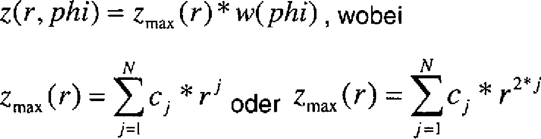
Das Höhenprofil, welches die spiralförmige Zusatzbrechkraft liefert, ist allgemein durch z(r, phi) = zmax(r, phi)·w(phi) beschrieben.The elevation profile which provides the helical addition power is generally described by z (r, phi) = zmax (r, phi) * w (phi).
Die Grundbrechkraft des Basissystems ergibt sich für sphärische Linsen aus der Formel![]()
![]()
Dabei ist beispielsweise R1 der Radius der ersten optischen Fläche, welcher real hergestellt wird und R2 ist der Radius der berechneten Basisfläche (die additive Höhe z, welche die Zusatzbrechkraft liefert, kann auch auf den Radius R1 aufaddiert werden oder auf beide Radien R1 und R2 aufgeteilt werden, die Formeln müssen dann entsprechend verändert werden).In this case, for example, R 1 is the radius of the first optical surface, which is manufactured real and R 2 is the radius of the calculated base surface (the additive height z, which provides the additional power can also be added to the radius R 1 or both radii R 1 and R 2 are divided, the formulas must then be changed accordingly).
Das Höhenprofil zL für die errechnete Basisfläche mit dem Radius R2 der sphärischen Linse ergibt sich zu![]()
![]()
![]()
![]()
![]()
![]()
Für den Fall einer sphärischen Basisfläche gilt daher In the case of a spherical base area therefore applies
![]()
![]()
Sofern nichtsphärische Basisflächen für die Linse zu Grunde gelegt werden, werden die bekannten Polynome für die Beschreibung nichtsphärischer Flächen zur Bestimmung der optischen Flächen und/oder der Basisfläche verwendet. Die Zusatzbrechkraft wird hier im Fall a) durch einen additiven Term z(r, phi) als Materialhöhe erzeugt, welcher beispielsweise auf die optische Basisfläche mit dem Radius R2 aufaddiert oder auch subtrahiert wird (Analoge Betrachtungen gelten auch für asphärische und Freiformflächen, die sich nicht mit einer einfachen Radienangabe beschreiben lassen.).If non-spherical base surfaces are used for the lens, the known polynomials are used for the description of non-spherical surfaces for determining the optical surfaces and / or the base surface. The additional refractive power is here in case a) by an additive term z (r, phi) generated as a material height, which is for example added to the optical base surface with the radius R 2 or subtracted (analogous considerations apply to aspherical and freeform surfaces, which can not be described with a simple radii.).
Das Radialpolynom für den maximalen Höhenanteil als Funktion des Radius r Brechkraft zmax(r), welches die maximale zur erzielende Dioptrienzahl verkörpert, ist: 
Der additive Term z(r, phi), welcher auf die Basisfläche der Linse addiert wird, ergibt sich aus 
Im einfachsten Falle reicht es daher bereits aus, die zusätzliche radiale Brechkraftverteilung als Produkt des normierten Azimutwinkels mit der maximal zu erreichenden Dioptrienzahl zu realisieren.In the simplest case, it is therefore already sufficient to realize the additional radial refractive power distribution as the product of the normalized azimuth angle with the maximum diopter number to be achieved.
Für das Radialpolynom zmax(r) kann in analoger Weise auch der Ansatz ![]()
![]()
Für den einfachsten Fall des Radialpolynoms zmax(r) = c1·r2
mit c1 als Koeffizienten vor dem quadratischen Term lautet die Gleichung für den additiven Term also
with c 1 as coefficients before the quadratic term, the equation for the additive term is
Das obige beschriebene Vorgehen stellt einen linearen „Schraubenanstieg” dar. In dieser Form ist die Abbildungsqualität über den gesamten Dioptrienbereich in etwa gleichbleibend gut.The procedure described above represents a linear "screw increase". In this form, the image quality over the entire dioptre range is approximately consistently good.
Oftmals ist es aber gewünscht, bestimmte Dioptrienbereiche wie zum Beispiel die Null-Dioptrien-Position zu bevorzugen. Hierzu ist es notwendig, die lineare Abhängigkeit der z-Höhe vom Winkel zu verlassen.Often, however, it is desirable to favor certain diopter ranges such as the zero diopter position. For this it is necessary to leave the linear dependence of the z-height on the angle.
Der winkelabhängige Anteil kann allgemein durch die Formel 
Ii die Peakintensitäten und ai > 0 die Dämpfungskoeffizienten für die jeweiligen Peaklagen sind.The angle-dependent portion can generally be represented by the formula
I i are the peak intensities and a i > 0 are the attenuation coefficients for the respective peak occurrences.
Beispielsweise lässt sich für M = 1; I1 = 1 und wi = 2π durch die Funktion 
Der geringe Anstieg zwischen phi = 0 und phi = 2 verursacht eine geringe Addition von Brechkraft in diesem Winkelbereich und somit einen größeren Flächenanteil für die Nulldioptrienentfernung.The small increase between phi = 0 and phi = 2 causes a small addition of refractive power in this angular range and thus a larger area fraction for the zero diopter distance.
Im Zusammenhang mit der Optimierung der Linse mit dem erweiterten Fokusbereich lassen sich weitere Vorteile erzielen, indem weitere Freiheitsgrade bei der Dimensionierung zur Verfügung stehen. Beispielsweise erfolgt dies, wenn die radiale Funktion zmax(r) ebenfalls einen azimutabhängigen Koeffizientensatz erhält und so das Radialpolynom zmax(r, phi) bestimmt wird als 
Daraus ergibt sich der additive Term z(r, phi) allgemein zu 
Daher lassen sich für den Winkelterm w(phi) noch weitere Varianten aus der allgemeinen Formel![]()
![]()
Die bisherigen Ausführungen basierten alle auf einem additiven Term, welcher refraktiv ist und auf eine der optischen Flächen des Basissystems addiert wird.The previous versions were all based on an additive term, which is refractive and is added to one of the optical surfaces of the base system.
Der Additionsterm kann natürlich auch in diffraktiver Form vorliegen, d. h. auf die sphärische Trägerfläche des Basissystems wird ein Diffraktives Optisches Element (DOE) aufgebracht, welches eine spiralförmige Phasenfunktion besitzt (Fall b)). Die Gestaltung dieser Phasenfunktion erfolgt dabei in vollkommener Analogie zum refraktiven Ansatz. Es eignen sich insbesondere Blaze-Gitter, Sinusgitter und Binär-Gitter.Of course, the addition term may also be in diffractive form, i. H. on the spherical support surface of the base system, a diffractive optical element (DOE) is applied, which has a spiral phase function (case b)). The design of this phase function takes place in complete analogy to the refractive approach. Blaze grids, sine grids and binary grids are particularly suitable.
Die Gitterfrequenz ändert sich radial und winkelabhängig spiralförmig stetig von einem Wert Null bis zu einem Maximalwert, welcher der maximalen Brechkraft entspricht. 
Die Gesamtbrechkraft der Linse ergibt sich aus einer vergleichsweise starken refraktiven Grundbrechkraft des monofokalen Basissystems und aus einem relativ kleinen Brechkraftanteil der diffraktiv erzeugten Zusatzbrechkraft:
So entsteht durch den diffraktiven Anteil ein relativ nur kleiner Farbfehler und die Linse mit dem erweiterten Fokusbereich ist auch für weißes Licht geeignet. Thus, due to the diffractive component, a relatively small color aberration is produced, and the lens with the extended focus range is also suitable for white light.
Der Additionsterm kann jedoch auch durch die Herstellung eines spiralförmigen Brechzahlgradienten realisiert werden (Fall c)). In
Die Gesamtbrechkraft FG ergibt sich aus der Grundbrechkraft FG des monofokalen Basissystems plus der Zusatzbrechkraft FS, welche durch die spiralförmige Brechkrafterhöhung bereitgestellt wird. ![]()
![]()
Die Brechungsindexdifferenz Δn(r, phi) läuft stetig von 0 (bei r = 0 und phi = 0) bis zur maximalen Brechungsindexerhöhung Δnmax (bei r = D/2 und phi = 2π wobei die Funktion w(phi) den oben beschriebenen linearen oder allgemeinen Verlauf vorgeben kann.The refractive index difference Δn (r, phi) runs continuously from 0 (at r = 0 and phi = 0) to the maximum refractive index increase Δn max (at r = D / 2 and phi = 2π) where the function w (phi) is the linear one described above or general course.
Dabei kann Δnmax gegenüber der Basisbrechzahl n2 der Linse sowohl positiv als auch negativ seinIn this case, Δn max can be both positive and negative with respect to the base refractive index n 2 of the lens
Die Erfindung wird nachfolgend an Hand von Figuren beschrieben. Es zeigen:The invention will be described below with reference to figures. Show it:
- a) „Aufaddieren” eines spiralförmigen Höhenprofils auf eine der optischen Flächen der
Linse gemäß Schritt 1, welche die Basisfläche ist. - b) „Aufaddieren” einer spiralförmigen diffraktiven Struktur auf eine der optischen Flächen der
Linse gemäß Schritt 1, welche die Basisfläche ist. - c) „Aufaddieren” eines spiralförmigen Brechungsindexverlaufes im Material der Linse.
- a) "adding up" a helical height profile on one of the optical surfaces of the lens according to
step 1, which is the base surface. - b) "adding up" a spiral diffractive structure to one of the optical surfaces of the lens according to
step 1, which is the base surface. - c) "adding up" a spiral refractive index profile in the material of the lens.
Im Beispiel hat die Linse herkömmliche sphärische optische Flächen und eine Linsendicke, die ein Basissystem bilden, welches mit einer „Basis-Brechzahl” von 1,5995 für 0 dpt Korrektur ausgelegt ist. Die zusätzliche spiralförmige Brechkraftverteilung wird durch einen spiralförmigen Brechungsindexgradienten realisiert und beginnt bei phi = 0 mit der Brechzahl von 1,5995. Die Brechzahl steigt radial- und winkelabhängig stetig spiralförmig und hat beispielsweise bei phi = π und r = D/2 eine Brechzahl von 1,61366. Das entspricht einer Brechkraft von 1,0 dpt. Die Brechzahl steigt weiter stetig an und hat bei phi = 2π und r = D/2 eine Brechzahl von 1,64615, was einer Brechkraft von 3,5 dpt entspricht. Zwischen phi = 0 und phi = 2π beträgt die Brechzahldifferenz 0,04665. Das entspricht einem nutzbaren kontinuierlichen Fokusbereich zwischen 0 dpt und 3,5 dpt.In the example, the lens has conventional spherical optical surfaces and a lens thickness which form a base system designed with a "base refractive index" of 1.5995 for 0 D correction. The additional spiral power distribution is realized by a spiral refractive index gradient and starts at phi = 0 with the refractive index of 1.5995. The refractive index increases steadily in a spiral-shaped manner depending on radial and angle and, for example, has a refractive index of 1.61366 at phi = π and r = D / 2. This corresponds to a refractive power of 1.0 dpt. The refractive index continues to increase steadily and has a refractive index of 1.64615 at phi = 2π and r = D / 2, which corresponds to a refractive power of 3.5 dpt. Between phi = 0 and phi = 2π, the refractive index difference is 0.04665. This corresponds to a usable continuous focus range between 0 dpt and 3.5 dpt.
Als Beispiel werden Parameter für eine Linse angegeben:
R1 = –15,1411 mm herzustellender Radius
R2 = 22,3164 mm berechneter Radius
d = 0,8 mm
n1 = 1 (Brechzahl außerhalb der Linse)
n2 = 1,56 (Brechzahl des Linsenmediums)
somit ergibt sich aus der Formel 
R 1 = -15.1411 mm radius to be produced
R 2 = 22.3164 mm calculated radius
d = 0.8 mm
n 1 = 1 (refractive index outside the lens)
n 2 = 1.56 (refractive index of the lens medium)
thus results from the formula
Auf die errechnete Basisfläche mit dem Radius R2 = 22,3164 mm wird ein linearer Schraubenanstieg gemäß der Formel
Mit c1 = –0,013 erhält man einen spiralförmigen Zusatz, welcher die Brennweite in Luft bis auf 20,57 mm erhöht, was 3,5 dpt entspricht.With c 1 = -0.013 one obtains a spiral addition, which increases the focal length in air up to 20.57 mm, which corresponds to 3.5 dpt.
Als Beispiel wird ein Handyobjektiv mit einer Brennweite von 5,61 mm gezeigt. Gemäß der Formel für den spiralförmigen, linearen Schraubenanstieg
Die optischen Flächen
Linse
- Dicke 1,738 mm; Material = ZeonexThickness 1.738 mm; Material = Zeonex
Erste optischen Fläche
- R1 = 1,7668 mmR 1 = 1.7668 mm
- Asphärenkoeffizienten = K = –0,162288 A = 0,472171E–04 B = 0,225901E–02 C = –0,179019E–03 D = –0,290228E–03 E = 0,131193E–03Aspheric coefficients K = -0.162288 A = 0.472171E-04 B = 0.225901E-02 C = -0.179019E-03 D = -0.290228E-03 E = 0.131193E-03
Zweite optische Fläche
Der berechnete Radius der Basisfläche
Die Oberflächenform der Basisfläche kann mit der Formel ![]()
![]()
Für jeden Flächenpunkt der Basisfläche ist die additive Höhe hinzuzurechnen, so dass sich das Gesamthöhenprofil der zweiten optischen Fläche durch folgende Formel bestimmt ist: ![]()
![]()
Linse 5
- Dicke 2,703 mm; Material = PolycarbonatThickness 2.703 mm; Material = polycarbonate
-
Fläche
17 : R = –3,85282 mm Asphärenkoeffizienten = K = 16,027906 A = –0,687655E–01 B = 0,676838E–01 C = –0,101439E+00 D = 0,900331E–02 E = 0,345714E–01 F = –0,101087E–01 G = 0,950453E–16 H = 0,443668E–17 J = 0,105965E–19area17 : R = -3.85282 mm aspheric coefficients = K = 16.027906 A = -0.687655E-01 B = 0.676838E-01 C = -0.101439E + 00 D = 0.900331E-02 E = 0.345714E -01 F = -0.101087E-01 G = 0.950453E-16 H = 0.443668E-17 J = 0,105965E-19 -
Fläche
18 : R4 = 413.75417 mm Asphärenkoeffizienten = K = –0.238656e57 A = –.200963E–01 B = 0.297531E–02 C = –.110276E–02 D = 0.209745E–03 E = –.935430E–05 F = –.430237E–05 G = 0.434653E–06 H = 0.475646E–07 J = –.612564E–08area18 : R 4 = 413.75417 mm Aspheric Coefficients = K = -0.238656e57 A = -.200963E-01 B = 0.297531E-02 C = -.110276E-02 D = 0.209745E-03 E = -.935430E-05 F = -. 430237E-05 G = 0.434653E-06 H = 0.475646E-07 J = -.612564E-08
Das optische System hat eine Baulänge von 6,8 mm. Die Öffnung beträgt 1:2,8. Das Objektiv liefert für einen Objektabstand von 330 mm bis unendlich eine ausreichend gute Bildqualität, welche ohne Nachfokussieren erreicht wird.The optical system has a length of 6.8 mm. The opening is 1: 2.8. The objective provides a sufficiently good image quality for an object distance of 330 mm to infinity, which is achieved without refocusing.
Es ist vorteilhaft, dass sich die spiralförmige optische zweite Fläche auf der Rückseite der Frontlinse befindet, wobei die übrige Fläche der Rückseite, welche nicht von der spiralförmigen optischen Fläche ausgefüllt ist, eine Blende
Ein weiteres Ausführungsbeispiel beschreibt ein Objektiv für eine Kamera mit einer Brennweite von f = 6,1 mm, bei einer Baulänge von 6,8 mm und einer Öffnung von 1:2,8. Die Darstellung entspricht der in
Die Linse
Alle optischen Flächen
- Linse
1 : Linsendicke = 1,59 mm, Material = Zeonex optische Fläche2 : R1 = 1,77985 Asphärenkoeffizienten = K = 0,113528 A = –0,369422E–02 B = 0,497838E–05 C = –0,526491E–03optische Fläche 4 entspricht der errechneten Fläche3 ): R2 = 4,43773 Asphärenkoeffizienten = K = 20,010847 A = –0,165668E–01 B = 0,598703E–01 C = –0,239849E+00 D = 0,363395E+00 E = –0,231421E+00
- lens
1 : Lens thickness = 1.59 mm, material = Zeonex optical surface2 : R 1 = 1.77985 aspheric coefficients = K = 0.113528 A = -0.369422E-02 B = 0.497838E-05 C = -0.526491E-03optical surface 4 corresponds to the calculated area3 ): R 2 = 4.43773 Aspheric coefficients = K = 20.010847 A = -0.165668E-01 B = 0.598703E-01 C = -0.239849E + 00 D = 0.363395E + 00 E = -0, 231421E + 00
Das Diffraktive Optische Element
Der zusätzliche spiralförmige Brechkraftanteil berechnet sich zu
Und die Gesamtbrechkraft ergibt sich zu
Die Linse
Fläche
Asphärenkoeffizienten =
K = 12.980316
A = –.289939E–01
B = –.193341E–01
C = 0.430879E–01
D = –.575934E–01
E = 0.345714E–01
F = –.101087E–01
Fläche
Asphärenkoeffizienten =
K = –0,238656857
A = –0,128992E–01
B = 0,257544E–02
C = –0,116486E–02
D = 0,176791E–03
E = –0,381907E–06
F = –0,294503E–05
G = 0,250155E–06
H = 0,303670E–08
J = –0,768736E–09The
area
Aspheric coefficients
K = 12.980316
A = -.289939E-01
B = -.193341E-01
C = 0.430879E-01
D = -575934E-01
E = 0.345714E-01
F = -.101087E-01
area
Aspheric coefficients
K = -0.238656857
A = -0.128992E-01
B = 0.257544E-02
C = -0.116486E-02
D = 0.176791E-03
E = -0.381907E-06
F = -0.294503E-05
G = 0.250155E-06
H = 0.303670E-08
J = -0.768736E-09
Der Abstand zwischen der Linse
Das Objektiv liefert einen gleichzeitigen Fokusbereich von 330 mm bis unendlich.The lens provides a simultaneous focus range from 330mm to infinity.
Dabei unterstützt insbesondere die zweckmäßige Wahl des Koeffizienten c vor dem quadratischen Term die Achromatisierung des Objektivs.In particular, the expedient choice of the coefficient c before the quadratic term supports the achromatization of the objective.
Die Intraokularlinse
R1 = –15,1411 mm (hergestellte erste optische Fläche
R2 = 22,3164 mm (berechnete Basisfläche
Linsendicke d = 0,8 mm
Brechzahl außerhalb der Linse n1 = 1,33
Brechzahl des Linsenmediums n2 = 1,56The
R 1 = -15.1411 mm (first optical surface produced
R 2 = 22.3164 mm (calculated base area
Lens thickness d = 0.8 mm
Refractive index outside the lens n 1 = 1.33
Refractive index of the lens medium n 2 = 1.56
Mit der Formel 
Die Zusatzbrechkraft ergibt sich aus der additiven Höhe auf der Basisfläche mit
Die „aufaddierte” Spiralfläche würde den Wert der Basisbrennweite von 16,233 mm auf 17.2 mm verlängern, was 3.5 dpt entspricht. Die erweiterte Fokuslinse liefert demnach eine Varianz des Dioptrienbereiches zwischen 0 dpt und 3,5 dpt.The "added" spiral surface would extend the value of the base focal length from 16.233 mm to 17.2 mm, which corresponds to 3.5 dpt. The extended focus lens thus provides a variance of the diopter range between 0 dpt and 3.5 dpt.
Aus Gründen der besseren Herstellbarkeit und um scharfe Übergänge zu vermeiden ist der Kurvenverlauf in der Nähe von 2π geglättet.For reasons of better manufacturability and to avoid sharp transitions, the curve in the vicinity of 2π is smoothed.

Der winkelabhängige Anteil w(phi) = exp⌊–a·(phi – 2π)2⌋
ist in
phi = 0 und phi = 2 verursacht eine geringe Addition von Brechkraft in diesem Winkelbereich und somit einen größeren Flächenanteil für die Nulldioptrienentfernung.The angle-dependent component w (phi) = exp⌊-a · (phi-2π) 2 ⌋
is in
phi = 0 and phi = 2 causes a small addition of refractive power in this angular range and thus a larger area fraction for the zero diopter distance.
In diesem Fall der Erzeugung der spiralförmigen Brechkraftverteilung der Linse mittels des diffraktiven Ansatzes lautet die Phasenfunktion: 
![]()

![]()
Für den linearen Spezialfall gilt:

Beispieldaten sind: Koeffizient des diffraktiven Polynoms k1 = 0.0025, die Höhe r im Bereich zwischen 0 bis 3 mm, der Azimutwinkel phi im Bereich von 0 bis 2π, Konstruktionswellenlänge des DOE wl = 550 nm, Profiltiefe h = 0.001 mm.Example data are: Coefficient of the diffractive polynomial k 1 = 0.0025, the height r in the range of 0 to 3 mm, the azimuth angle phi in the range of 0 to 2π, design wavelength of the DOE wl = 550 nm, profile depth h = 0.001 mm.
Ein Verlauf des winkelabhängigen Faktors w(phi) ist in
Mit der modifizierten Formel für die Winkelabhängigkeit
- w1, w2:
- Peak-Lagen (zwischen 0 und 2·pi),
- I1, I2:
- Peakintensitäten und
- a1, a2:
- Dämpfungskoeffizienten für die beiden Peaks
I1 = 0,9; I2 = 0,1; a1 = 0,8; a2 = 0,1; w1 = 1,8; w2 = 4,5
ein Verlauf für die Azimutabhängigkeit, bei dem ein ausgedehnter Bereich für die stärkste Dioptrienlage (ca. 3 dpt) reserviert wird.With the modified formula for the angle dependence
- w 1 , w 2 :
- Peak positions (between 0 and 2 · pi),
- I 1 , I 2 :
- Peak intensities and
- a 1 , a 2 :
- Attenuation coefficients for the two peaks
I 1 = 0.9; I 2 = 0.1; a 1 = 0.8; a 2 = 0.1; w 1 = 1.8; w 2 = 4.5
a course for the azimuth dependence, in which an extended area for the strongest diopter position (about 3 dpt) is reserved.
Mit den Werten I1 = 0,9; I2 = 0,1; a1 = 0,8; a2 = 0,1; w1 = 4,5; w2 = 0,5 wird mit der Formel
Bezugszeichenliste LIST OF REFERENCE NUMBERS
- 11
- Linselens
- 22
- gefertigte erste optische Fläche (sphärisch, asphärisch, radialsymmetrisch, Freiformfläche)manufactured first optical surface (spherical, aspherical, radially symmetric, free-form surface)
- 33
- berechnete Basisfläche (sphärisch, asphärisch, radialsymmetrisch, Freiformfläche)calculated base area (spherical, aspherical, radially symmetric, free-form surface)
- 44
- gefertigte zweite optische Fläche (sphärisch, asphärisch, radialsymmetrisch, Freiformfläche, spiralförmige Oberfläche)fabricated second optical surface (spherical, aspherical, radially symmetric, free-form surface, spiral-shaped surface)
- 55
- asphärische Linseaspherical lens
- 66
- Filterfilter
- 77
- Sensorsensor
- 88th
- Lichtbündellight beam
- 99
- Linsenrandlens edge
- 1010
- optische Achseoptical axis
- 1111
- Intraokularlinseintraocular lens
- 1212
- Corneacornea
- 1313
- Kammerwasseraqueous humor
- 1414
- Retinaretina
- 1515
- Blendecover
- 1616
- spiralförmiges Diffraktives Optisches Element (DOE)spiral diffractive optical element (DOE)
- 1717
- optische Flächeoptical surface
- 1818
- optische Flächeoptical surface
- FG F G
- Gesamtbrechkraft der LinseTotal refractive power of the lens
- FL F L
- Brechkraft des Basissystems der LinsePower of the base system of the lens
- FS(r, phi)F S (r, phi)
- Brechkraft, die durch den spiralförmigen Anteil zur Brechkraft des Basissystems hinzu kommtRefractive power, which is added by the spiral portion to the refractive power of the base system
- FS max F S max
- maximale Brechkraftmaximum refractive power
- fL f L
- Brennweite des BasissystemsFocal length of the base system
- fS(r, phi)f S (r, phi)
- Brennweite der spiralförmigen Zusatzbrechkraft N, M EndwerteFocal length of the spiral additional power N, M final values
- i, ji, j
- Zählwertecounts
- cj, c1, c2 c j , c 1 , c 2
- Polynomkoeffizienten für den retraktiven FallPolynomial coefficients for the retractive case
- kj, k1, k2 k j , k 1 , k 2
- Polynomkoeffizienten für den diffraktiven FallPolynomial coefficients for the diffractive case
- zmax(r) zmax (r)
- maximale Höhe, Radius-abhängigmaximum height, radius-dependent
- zmax(r, phi)z max (r, phi)
- maximale Höhe, Radius-abhängig und Azimutwinkel-abhängigmaximum height, radius-dependent and azimuth angle-dependent
- z(r, phi)z (r, phi)
- additive Höhe auf der Basisflächeadditive height on the base surface
- zL(r)z L (r)
- Höhenprofil der berechneten BasisflächeHeight profile of the calculated base area
- zG(r, phi)z G (r, phi)
- Höhenprofil der gefertigten optischen FlächeHeight profile of the manufactured optical surface
- w(phi)w (phi)
- winkelabhängiger Anteil des BrechkraftverlaufesAngular component of the refractive power curve
- wi, w1, w2 w i , w 1 , w 2
- Peaklagen der WinkelverteilungsfunktionPeaklagen the angular distribution function
- ai, a1, a2 a i , a 1 , a 2
- Dämpfungskoeffizienten für die jeweiligen PeaklagenDamping coefficients for the respective peak actions
- Ii, I1, I2 I i , I 1 , I 2
- Intensitätswerte der EinzelpeaksIntensity values of the individual peaks
- DD
- LinsendurchmesserLens diameter
- rr
- Radius (radiale Höhe)Radius (radial height)
- phiphi
- Azimutwinkelazimuth angle
- R1 R 1
- Radius der ersten optischen FlächeRadius of the first optical surface
- R2 R 2
- Radius der optischen BasisflächeRadius of the optical base surface
- n1 n 1
- Brechzahl des umgebenden MediumsRefractive index of the surrounding medium
- n2 n 2
- Brechzahl der LinseRefractive index of the lens
- dd
- Linsendickelens thickness
- hH
- Profiltiefe des diffraktiven ElementsProfile depth of the diffractive element
- λλ
- AnwendungswellenlängeApplication wavelength
- wlwl
- Konstruktionswellenlänge des diffraktiven ElementsDesign wavelength of the diffractive element
- tt
- Rechengrößeoperand
- floor(t)floor (t)
- ganzzahliger Anteilinteger share
- Phasemax(r, phi)Phase max (r, phi)
- Maximalwert der Gitterfrequenz, welcher der maximalen Brechkraft entsprichtMaximum value of the grid frequency, which corresponds to the maximum refractive power
- Phase(r, phi)Phase (r, phi)
- Phasenfunktionphase function
- Profil(r, phi)Profile (r, phi)
- auf die Höhe h reduzierte PhasenfunktionPhase function reduced to the height h
- x, yx, y
- karthesische KoordinatenCartesian coordinates
ZITATE ENTHALTEN IN DER BESCHREIBUNG QUOTES INCLUDE IN THE DESCRIPTION
Diese Liste der vom Anmelder aufgeführten Dokumente wurde automatisiert erzeugt und ist ausschließlich zur besseren Information des Lesers aufgenommen. Die Liste ist nicht Bestandteil der deutschen Patent- bzw. Gebrauchsmusteranmeldung. Das DPMA übernimmt keinerlei Haftung für etwaige Fehler oder Auslassungen.This list of the documents listed by the applicant has been generated automatically and is included solely for the better information of the reader. The list is not part of the German patent or utility model application. The DPMA assumes no liability for any errors or omissions.
Zitierte PatentliteraturCited patent literature
- US 5982543 A [0005] US 5982543 A [0005]
- US 6120148 A [0006] US 6120148 A [0006]
- US 6536899 B [0006] US 6536899 B [0006]
- US 2006176572 A [0007] US 2006176572 A [0007]
- WO 10083546 A [0008] WO 10083546 A [0008]
- US 20100002310 A1 [0009] US 20100002310 Al [0009]
- DE 102009033984 A1 [0056] DE 102009033984 A1 [0056]
Claims (15)


Priority Applications (7)
| Application Number | Priority Date | Filing Date | Title |
|---|---|---|---|
| DE102011101899A DE102011101899A1 (en) | 2011-05-18 | 2011-05-18 | Lens with an extended focus area |
| PCT/EP2012/002098 WO2012156081A1 (en) | 2011-05-18 | 2012-05-16 | Lens with an extended focal range |
| AU2012258064A AU2012258064C1 (en) | 2011-05-18 | 2012-05-16 | Lens with an extended focal range |
| US14/118,539 US9703018B2 (en) | 2011-05-18 | 2012-05-16 | Lens with an extended range of focus |
| CN201280035810.XA CN103703407B (en) | 2011-05-18 | 2012-05-16 | Lenses with extended focus range |
| ES12723377T ES2859786T3 (en) | 2011-05-18 | 2012-05-16 | Lens with an extended focus range |
| EP12723377.3A EP2710426B1 (en) | 2011-05-18 | 2012-05-16 | Lens with an extended focal range |
Applications Claiming Priority (1)
| Application Number | Priority Date | Filing Date | Title |
|---|---|---|---|
| DE102011101899A DE102011101899A1 (en) | 2011-05-18 | 2011-05-18 | Lens with an extended focus area |
Publications (1)
| Publication Number | Publication Date |
|---|---|
| DE102011101899A1 true DE102011101899A1 (en) | 2012-11-22 |
Family
ID=46149382
Family Applications (1)
| Application Number | Title | Priority Date | Filing Date |
|---|---|---|---|
| DE102011101899A Withdrawn DE102011101899A1 (en) | 2011-05-18 | 2011-05-18 | Lens with an extended focus area |
Country Status (7)
| Country | Link |
|---|---|
| US (1) | US9703018B2 (en) |
| EP (1) | EP2710426B1 (en) |
| CN (1) | CN103703407B (en) |
| AU (1) | AU2012258064C1 (en) |
| DE (1) | DE102011101899A1 (en) |
| ES (1) | ES2859786T3 (en) |
| WO (1) | WO2012156081A1 (en) |
Cited By (3)
| Publication number | Priority date | Publication date | Assignee | Title |
|---|---|---|---|---|
| DE102011114752A1 (en) | 2011-09-29 | 2013-04-04 | Carl Zeiss Ag | Lens with an extended focus area |
| WO2015022218A1 (en) * | 2013-08-13 | 2015-02-19 | Carl Zeiss Meditec Ag | Multifocal eye lens with optical zones which at least partly encircle a main optical axis |
| WO2015022216A1 (en) * | 2013-08-13 | 2015-02-19 | Carl Zeiss Meditec Ag | Eye lens, in particular intraocular lens, having a toric refractive surface profile and a helix winding as a surface structure on an optical part |
Families Citing this family (27)
| Publication number | Priority date | Publication date | Assignee | Title |
|---|---|---|---|---|
| TWI588560B (en) | 2012-04-05 | 2017-06-21 | 布萊恩荷登視覺協會 | Lens, device, method and system for refractive error |
| US9201250B2 (en) | 2012-10-17 | 2015-12-01 | Brien Holden Vision Institute | Lenses, devices, methods and systems for refractive error |
| TWI600418B (en) | 2012-10-17 | 2017-10-01 | 布萊恩荷登視覺協會 | Lens, device, method and system for refractive error |
| WO2016035055A1 (en) * | 2014-09-05 | 2016-03-10 | Hoya Corporation | Wide depth of focus vortex intraocular lenses and associated methods |
| US11696823B2 (en) | 2015-04-14 | 2023-07-11 | Z Optics, Inc. | High definition and extended depth of field intraocular lens |
| BR112017021858A2 (en) * | 2015-04-15 | 2018-07-10 | Vision Ease, Lp | ophthalmic lens with graduated microlenses. |
| EP3432768B1 (en) | 2016-03-23 | 2020-04-29 | Johnson & Johnson Surgical Vision, Inc. | Power calculator for an ophthalmic apparatus with corrective meridians having extended tolerance or operation band |
| EP3433667B1 (en) * | 2016-03-23 | 2022-09-28 | Johnson & Johnson Surgical Vision, Inc. | Ophthalmic apparatus with corrective meridians having extended tolerance band with freeform refractive surfaces |
| WO2018078439A2 (en) | 2016-10-25 | 2018-05-03 | Amo Groningen B.V. | Realistic eye models to design and evaluate intraocular lenses for a large field of view |
| EP3594725A4 (en) * | 2017-03-07 | 2020-12-16 | Nippon Sheet Glass Company, Limited | Optical component and method for producing optical component |
| US10739227B2 (en) | 2017-03-23 | 2020-08-11 | Johnson & Johnson Surgical Vision, Inc. | Methods and systems for measuring image quality |
| EP3435113B1 (en) * | 2017-07-23 | 2021-11-03 | NXP USA, Inc. | Method of detecting an object |
| EP3687447A1 (en) | 2017-11-30 | 2020-08-05 | AMO Groningen B.V. | Intraocular lenses that improve post-surgical spectacle independent and methods of manufacturing thereof |
| US12357509B2 (en) | 2019-04-05 | 2025-07-15 | Amo Groningen B.V. | Systems and methods for improving vision from an intraocular lens in an incorrect position and using refractive index writing |
| US11583388B2 (en) | 2019-04-05 | 2023-02-21 | Amo Groningen B.V. | Systems and methods for spectacle independence using refractive index writing with an intraocular lens |
| US11678975B2 (en) | 2019-04-05 | 2023-06-20 | Amo Groningen B.V. | Systems and methods for treating ocular disease with an intraocular lens and refractive index writing |
| US11529230B2 (en) | 2019-04-05 | 2022-12-20 | Amo Groningen B.V. | Systems and methods for correcting power of an intraocular lens using refractive index writing |
| US11583389B2 (en) | 2019-04-05 | 2023-02-21 | Amo Groningen B.V. | Systems and methods for correcting photic phenomenon from an intraocular lens and using refractive index writing |
| US11564839B2 (en) | 2019-04-05 | 2023-01-31 | Amo Groningen B.V. | Systems and methods for vergence matching of an intraocular lens with refractive index writing |
| US11944574B2 (en) | 2019-04-05 | 2024-04-02 | Amo Groningen B.V. | Systems and methods for multiple layer intraocular lens and using refractive index writing |
| US12377622B2 (en) | 2019-04-05 | 2025-08-05 | Amo Groningen B.V. | Systems and methods for vergence matching with an optical profile and using refractive index writing |
| US11172112B2 (en) | 2019-09-09 | 2021-11-09 | Embedtek, LLC | Imaging system including a non-linear reflector |
| US11754858B2 (en) * | 2020-04-30 | 2023-09-12 | Coopervision International Limited | Multifocal ophthalmic lens and related methods |
| US11934043B2 (en) | 2020-04-30 | 2024-03-19 | Coopervision International Limited | Myopia control lens and related methods |
| US11762220B2 (en) * | 2020-04-30 | 2023-09-19 | Coopervision International Limited | Multifocal ophthalmic lenses and related methods |
| AU2021431053B2 (en) * | 2021-03-02 | 2025-03-06 | Rayner Intraocular Lenses Limited | Intraocular lens with focal performance tailored to pupil size deploying refractive power modification along spiral tracks |
| WO2022233683A1 (en) | 2021-05-05 | 2022-11-10 | Amo Groningen B.V. | Ring halometer system and method for quantifying dysphotopsias |
Citations (11)
| Publication number | Priority date | Publication date | Assignee | Title |
|---|---|---|---|---|
| DE3617363A1 (en) * | 1986-05-23 | 1987-11-26 | Schott Glaswerke | METHOD FOR THE PRODUCTION OF CYLINDRICAL SYMMETRICAL BODIES WITH PRESET RADIAL FALLING PHYSICAL MATERIAL PROPERTIES AND APPLICATIONS |
| US5982543A (en) | 1994-03-17 | 1999-11-09 | Bifocon Optics Forschungs-Und Entwicklungsgmbh | Zoned lens |
| US6120148A (en) | 1998-10-05 | 2000-09-19 | Bifocon Optics Gmbh | Diffractive lens |
| DE10161329A1 (en) * | 2000-12-15 | 2002-07-04 | Agilent Technologies Inc | Optical diffraction element for providing an inexpensive multimode fiber coupling and reflection management |
| US6536899B1 (en) | 1999-07-14 | 2003-03-25 | Bifocon Optics Gmbh | Multifocal lens exhibiting diffractive and refractive powers |
| WO2003054616A2 (en) * | 2001-12-20 | 2003-07-03 | Johnson & Johnson Vision Care, Inc. | Multifocal ophthalmic lenses |
| US20060176572A1 (en) | 2003-06-30 | 2006-08-10 | Fiala Werner J | Intra-ocular lens or contact lens exhibiting lardge depth of focus |
| US20100002310A1 (en) | 2008-07-03 | 2010-01-07 | Micron Technology, Inc. | Extended Depth-of-Field Lenses and Methods For Their Design, Optimization and Manufacturing |
| WO2010083546A2 (en) | 2009-01-21 | 2010-07-29 | Werner Fiala | Lens having circular refractive power profile |
| US20100329605A1 (en) * | 2009-06-26 | 2010-12-30 | Graham Luke | optical subassembly for coupling light into an optical waveguide |
| DE102009033984A1 (en) | 2009-07-16 | 2011-02-03 | Fachhochschule Jena | Process for producing glass with defined inhomogeneous optical properties |
Family Cites Families (8)
| Publication number | Priority date | Publication date | Assignee | Title |
|---|---|---|---|---|
| US5106180A (en) * | 1991-05-30 | 1992-04-21 | Robert Marie | Multifocal ophthalmic lens |
| IL109375A0 (en) * | 1993-04-26 | 1994-07-31 | Ciba Geigy Ag | Multifocal contact lens |
| US5861934A (en) * | 1996-05-06 | 1999-01-19 | Innotech, Inc. | Refractive index gradient lens |
| EP2069851A4 (en) * | 2006-09-14 | 2010-02-24 | Tessera Tech Hungary Kft | IMAGING SYSTEM WITH ASSOUPLY ASSEMBLED TOLERANCES AND ASSOCIATED METHODS |
| WO2008087486A2 (en) * | 2006-09-14 | 2008-07-24 | Tessera Technologies Hungary Kft. | Imaging system with improved image quality and associated methods |
| WO2008051592A2 (en) * | 2006-10-25 | 2008-05-02 | Volk Donald A | Multi-layered gradient index progressive lens |
| US20100238400A1 (en) * | 2006-10-25 | 2010-09-23 | Volk Donald A | Multi-layered gradient index progressive lens |
| KR101422503B1 (en) * | 2008-05-09 | 2014-07-25 | 삼성전자주식회사 | Lens with extended depth of focus and optical system having the same |
-
2011
- 2011-05-18 DE DE102011101899A patent/DE102011101899A1/en not_active Withdrawn
-
2012
- 2012-05-16 EP EP12723377.3A patent/EP2710426B1/en active Active
- 2012-05-16 CN CN201280035810.XA patent/CN103703407B/en active Active
- 2012-05-16 ES ES12723377T patent/ES2859786T3/en active Active
- 2012-05-16 US US14/118,539 patent/US9703018B2/en active Active
- 2012-05-16 AU AU2012258064A patent/AU2012258064C1/en active Active
- 2012-05-16 WO PCT/EP2012/002098 patent/WO2012156081A1/en not_active Ceased
Patent Citations (11)
| Publication number | Priority date | Publication date | Assignee | Title |
|---|---|---|---|---|
| DE3617363A1 (en) * | 1986-05-23 | 1987-11-26 | Schott Glaswerke | METHOD FOR THE PRODUCTION OF CYLINDRICAL SYMMETRICAL BODIES WITH PRESET RADIAL FALLING PHYSICAL MATERIAL PROPERTIES AND APPLICATIONS |
| US5982543A (en) | 1994-03-17 | 1999-11-09 | Bifocon Optics Forschungs-Und Entwicklungsgmbh | Zoned lens |
| US6120148A (en) | 1998-10-05 | 2000-09-19 | Bifocon Optics Gmbh | Diffractive lens |
| US6536899B1 (en) | 1999-07-14 | 2003-03-25 | Bifocon Optics Gmbh | Multifocal lens exhibiting diffractive and refractive powers |
| DE10161329A1 (en) * | 2000-12-15 | 2002-07-04 | Agilent Technologies Inc | Optical diffraction element for providing an inexpensive multimode fiber coupling and reflection management |
| WO2003054616A2 (en) * | 2001-12-20 | 2003-07-03 | Johnson & Johnson Vision Care, Inc. | Multifocal ophthalmic lenses |
| US20060176572A1 (en) | 2003-06-30 | 2006-08-10 | Fiala Werner J | Intra-ocular lens or contact lens exhibiting lardge depth of focus |
| US20100002310A1 (en) | 2008-07-03 | 2010-01-07 | Micron Technology, Inc. | Extended Depth-of-Field Lenses and Methods For Their Design, Optimization and Manufacturing |
| WO2010083546A2 (en) | 2009-01-21 | 2010-07-29 | Werner Fiala | Lens having circular refractive power profile |
| US20100329605A1 (en) * | 2009-06-26 | 2010-12-30 | Graham Luke | optical subassembly for coupling light into an optical waveguide |
| DE102009033984A1 (en) | 2009-07-16 | 2011-02-03 | Fachhochschule Jena | Process for producing glass with defined inhomogeneous optical properties |
Cited By (5)
| Publication number | Priority date | Publication date | Assignee | Title |
|---|---|---|---|---|
| DE102011114752A1 (en) | 2011-09-29 | 2013-04-04 | Carl Zeiss Ag | Lens with an extended focus area |
| US9690882B2 (en) | 2011-09-29 | 2017-06-27 | Carl Zeiss Ag | Lens having an extended range of focus and method of making the same |
| WO2015022218A1 (en) * | 2013-08-13 | 2015-02-19 | Carl Zeiss Meditec Ag | Multifocal eye lens with optical zones which at least partly encircle a main optical axis |
| WO2015022216A1 (en) * | 2013-08-13 | 2015-02-19 | Carl Zeiss Meditec Ag | Eye lens, in particular intraocular lens, having a toric refractive surface profile and a helix winding as a surface structure on an optical part |
| DE102013215984A1 (en) | 2013-08-13 | 2015-03-05 | Carl Zeiss Meditec Ag | An ophthalmic lens, in particular an intraocular lens, with a toric refractive surface profile and a helical turn as surface structure on an optical part |
Also Published As
| Publication number | Publication date |
|---|---|
| EP2710426A1 (en) | 2014-03-26 |
| WO2012156081A1 (en) | 2012-11-22 |
| CN103703407A (en) | 2014-04-02 |
| EP2710426B1 (en) | 2020-12-16 |
| AU2012258064C1 (en) | 2016-03-10 |
| CN103703407B (en) | 2016-05-04 |
| ES2859786T3 (en) | 2021-10-04 |
| US20140293426A1 (en) | 2014-10-02 |
| AU2012258064B2 (en) | 2015-11-26 |
| US9703018B2 (en) | 2017-07-11 |
| AU2012258064A1 (en) | 2013-12-19 |
Similar Documents
| Publication | Publication Date | Title |
|---|---|---|
| DE102011101899A1 (en) | Lens with an extended focus area | |
| EP2761359B1 (en) | Lens having an extended focal range | |
| DE69715830T2 (en) | IMPROVED DIFFERENTIAL MULTIFOCAL INTRAOCULAR LENS | |
| DE60016219T2 (en) | BREAKING / BENDING MULTIFOCALLINSE | |
| DE69317804T2 (en) | Segmented multifocal contact lens with undivided central part | |
| DE69127734T2 (en) | Multifocal diffractive lens for the correction of visual defects | |
| DE202008003859U1 (en) | Multifocal intraocular lens | |
| EP3391129B1 (en) | Opthalmological optical element and method for constructing an opthalmological optical element | |
| DE102009010538A1 (en) | Optical element having an optically effective surface, which at least partially has a Fresnel structure with a plurality of Fresnel segments, and methods for producing such an optical element | |
| DE202009018881U1 (en) | Aphakic intraocular lens | |
| DE102014004381A1 (en) | Improved ophthalmic lens for presbyopia correction | |
| DE102007057122A1 (en) | Intraocular lens for implantation in eye, particularly human eye, has lens, which has optical axis, anterior optical surface that is transverse to optical axis, and posterior optical surface that is opposite to anterior optical surface | |
| WO2013079312A1 (en) | Optical device, optical element and method for producing it | |
| DE102013100680A1 (en) | Wave front manipulator for optical system used in e.g. observation optical device like telescope, has two optical components arranged movable relative to each other, opposing optical axis and set rotatable along vertical rotation axis | |
| WO2010028418A1 (en) | Lens having independent non-interfering partial zones | |
| DE102011113980A1 (en) | Lens system with variable refraction strength | |
| WO2008080464A1 (en) | Intraocular lens | |
| EP1863411B1 (en) | Intraocular lens | |
| DE102007044228A1 (en) | Optical device | |
| DE202016105181U1 (en) | Multifocal eye lens with ring zones with defined different average powers | |
| DE102016117504B4 (en) | Multifocal eye lens with ring zones with defined different average powers | |
| EP4343414B1 (en) | Multifocal lens | |
| DE102023125130A1 (en) | Lens for a head-mounted display, head-mounted display and method for designing and manufacturing a lens | |
| WO2022233947A1 (en) | Artificial eye lens and method for production thereof | |
| DE102020201817A1 (en) | Diffractive lens of the eye |
Legal Events
| Date | Code | Title | Description |
|---|---|---|---|
| R012 | Request for examination validly filed | ||
| R016 | Response to examination communication | ||
| R120 | Application withdrawn or ip right abandoned |