US7937211B2 - Internal combustion engine torque control - Google Patents
Internal combustion engine torque control Download PDFInfo
- Publication number
- US7937211B2 US7937211B2 US12/530,517 US53051708A US7937211B2 US 7937211 B2 US7937211 B2 US 7937211B2 US 53051708 A US53051708 A US 53051708A US 7937211 B2 US7937211 B2 US 7937211B2
- Authority
- US
- United States
- Prior art keywords
- acceleration
- internal combustion
- combustion engine
- torque
- torque gradient
- Prior art date
- Legal status (The legal status is an assumption and is not a legal conclusion. Google has not performed a legal analysis and makes no representation as to the accuracy of the status listed.)
- Expired - Fee Related
Links
- 238000002485 combustion reaction Methods 0.000 title claims abstract description 136
- 230000001133 acceleration Effects 0.000 claims abstract description 279
- 230000008859 change Effects 0.000 claims abstract description 53
- 238000000034 method Methods 0.000 claims description 14
- 238000001514 detection method Methods 0.000 claims description 11
- 238000012937 correction Methods 0.000 claims description 8
- 230000035939 shock Effects 0.000 description 28
- 230000003247 decreasing effect Effects 0.000 description 11
- 230000002596 correlated effect Effects 0.000 description 5
- 230000007423 decrease Effects 0.000 description 5
- 230000000694 effects Effects 0.000 description 5
- 239000000446 fuel Substances 0.000 description 5
- 239000003054 catalyst Substances 0.000 description 4
- 230000001276 controlling effect Effects 0.000 description 4
- 230000008569 process Effects 0.000 description 4
- 230000000052 comparative effect Effects 0.000 description 3
- 238000002347 injection Methods 0.000 description 3
- 239000007924 injection Substances 0.000 description 3
- 230000004048 modification Effects 0.000 description 3
- 238000012986 modification Methods 0.000 description 3
- 238000004891 communication Methods 0.000 description 2
- 230000000875 corresponding effect Effects 0.000 description 2
- 230000006866 deterioration Effects 0.000 description 2
- 238000000746 purification Methods 0.000 description 2
- 230000000979 retarding effect Effects 0.000 description 2
- 238000011144 upstream manufacturing Methods 0.000 description 2
- 230000009194 climbing Effects 0.000 description 1
- 230000007246 mechanism Effects 0.000 description 1
- 230000002093 peripheral effect Effects 0.000 description 1
- 230000009467 reduction Effects 0.000 description 1
- 230000001105 regulatory effect Effects 0.000 description 1
Images


Classifications
-
- F—MECHANICAL ENGINEERING; LIGHTING; HEATING; WEAPONS; BLASTING
- F02—COMBUSTION ENGINES; HOT-GAS OR COMBUSTION-PRODUCT ENGINE PLANTS
- F02D—CONTROLLING COMBUSTION ENGINES
- F02D41/00—Electrical control of supply of combustible mixture or its constituents
- F02D41/0002—Controlling intake air
-
- F—MECHANICAL ENGINEERING; LIGHTING; HEATING; WEAPONS; BLASTING
- F02—COMBUSTION ENGINES; HOT-GAS OR COMBUSTION-PRODUCT ENGINE PLANTS
- F02D—CONTROLLING COMBUSTION ENGINES
- F02D41/00—Electrical control of supply of combustible mixture or its constituents
- F02D41/02—Circuit arrangements for generating control signals
- F02D41/04—Introducing corrections for particular operating conditions
- F02D41/10—Introducing corrections for particular operating conditions for acceleration
-
- F—MECHANICAL ENGINEERING; LIGHTING; HEATING; WEAPONS; BLASTING
- F02—COMBUSTION ENGINES; HOT-GAS OR COMBUSTION-PRODUCT ENGINE PLANTS
- F02D—CONTROLLING COMBUSTION ENGINES
- F02D41/00—Electrical control of supply of combustible mixture or its constituents
- F02D41/24—Electrical control of supply of combustible mixture or its constituents characterised by the use of digital means
- F02D41/2406—Electrical control of supply of combustible mixture or its constituents characterised by the use of digital means using essentially read only memories
- F02D41/2425—Particular ways of programming the data
- F02D41/2429—Methods of calibrating or learning
- F02D41/2441—Methods of calibrating or learning characterised by the learning conditions
-
- F—MECHANICAL ENGINEERING; LIGHTING; HEATING; WEAPONS; BLASTING
- F02—COMBUSTION ENGINES; HOT-GAS OR COMBUSTION-PRODUCT ENGINE PLANTS
- F02D—CONTROLLING COMBUSTION ENGINES
- F02D41/00—Electrical control of supply of combustible mixture or its constituents
- F02D41/24—Electrical control of supply of combustible mixture or its constituents characterised by the use of digital means
- F02D41/2406—Electrical control of supply of combustible mixture or its constituents characterised by the use of digital means using essentially read only memories
- F02D41/2425—Particular ways of programming the data
- F02D41/2429—Methods of calibrating or learning
- F02D41/2451—Methods of calibrating or learning characterised by what is learned or calibrated
-
- F—MECHANICAL ENGINEERING; LIGHTING; HEATING; WEAPONS; BLASTING
- F02—COMBUSTION ENGINES; HOT-GAS OR COMBUSTION-PRODUCT ENGINE PLANTS
- F02P—IGNITION, OTHER THAN COMPRESSION IGNITION, FOR INTERNAL-COMBUSTION ENGINES; TESTING OF IGNITION TIMING IN COMPRESSION-IGNITION ENGINES
- F02P5/00—Advancing or retarding ignition; Control therefor
- F02P5/04—Advancing or retarding ignition; Control therefor automatically, as a function of the working conditions of the engine or vehicle or of the atmospheric conditions
- F02P5/145—Advancing or retarding ignition; Control therefor automatically, as a function of the working conditions of the engine or vehicle or of the atmospheric conditions using electrical means
- F02P5/15—Digital data processing
- F02P5/1502—Digital data processing using one central computing unit
- F02P5/1504—Digital data processing using one central computing unit with particular means during a transient phase, e.g. acceleration, deceleration, gear change
-
- F—MECHANICAL ENGINEERING; LIGHTING; HEATING; WEAPONS; BLASTING
- F02—COMBUSTION ENGINES; HOT-GAS OR COMBUSTION-PRODUCT ENGINE PLANTS
- F02D—CONTROLLING COMBUSTION ENGINES
- F02D11/00—Arrangements for, or adaptations to, non-automatic engine control initiation means, e.g. operator initiated
- F02D11/06—Arrangements for, or adaptations to, non-automatic engine control initiation means, e.g. operator initiated characterised by non-mechanical control linkages, e.g. fluid control linkages or by control linkages with power drive or assistance
- F02D11/10—Arrangements for, or adaptations to, non-automatic engine control initiation means, e.g. operator initiated characterised by non-mechanical control linkages, e.g. fluid control linkages or by control linkages with power drive or assistance of the electric type
- F02D2011/101—Arrangements for, or adaptations to, non-automatic engine control initiation means, e.g. operator initiated characterised by non-mechanical control linkages, e.g. fluid control linkages or by control linkages with power drive or assistance of the electric type characterised by the means for actuating the throttles
- F02D2011/102—Arrangements for, or adaptations to, non-automatic engine control initiation means, e.g. operator initiated characterised by non-mechanical control linkages, e.g. fluid control linkages or by control linkages with power drive or assistance of the electric type characterised by the means for actuating the throttles at least one throttle being moved only by an electric actuator
-
- F—MECHANICAL ENGINEERING; LIGHTING; HEATING; WEAPONS; BLASTING
- F02—COMBUSTION ENGINES; HOT-GAS OR COMBUSTION-PRODUCT ENGINE PLANTS
- F02D—CONTROLLING COMBUSTION ENGINES
- F02D2200/00—Input parameters for engine control
- F02D2200/02—Input parameters for engine control the parameters being related to the engine
- F02D2200/04—Engine intake system parameters
- F02D2200/0406—Intake manifold pressure
- F02D2200/0408—Estimation of intake manifold pressure
-
- F—MECHANICAL ENGINEERING; LIGHTING; HEATING; WEAPONS; BLASTING
- F02—COMBUSTION ENGINES; HOT-GAS OR COMBUSTION-PRODUCT ENGINE PLANTS
- F02D—CONTROLLING COMBUSTION ENGINES
- F02D2200/00—Input parameters for engine control
- F02D2200/02—Input parameters for engine control the parameters being related to the engine
- F02D2200/10—Parameters related to the engine output, e.g. engine torque or engine speed
- F02D2200/1002—Output torque
- F02D2200/1004—Estimation of the output torque
-
- F—MECHANICAL ENGINEERING; LIGHTING; HEATING; WEAPONS; BLASTING
- F02—COMBUSTION ENGINES; HOT-GAS OR COMBUSTION-PRODUCT ENGINE PLANTS
- F02D—CONTROLLING COMBUSTION ENGINES
- F02D2200/00—Input parameters for engine control
- F02D2200/60—Input parameters for engine control said parameters being related to the driver demands or status
- F02D2200/602—Pedal position
-
- F—MECHANICAL ENGINEERING; LIGHTING; HEATING; WEAPONS; BLASTING
- F02—COMBUSTION ENGINES; HOT-GAS OR COMBUSTION-PRODUCT ENGINE PLANTS
- F02D—CONTROLLING COMBUSTION ENGINES
- F02D2200/00—Input parameters for engine control
- F02D2200/70—Input parameters for engine control said parameters being related to the vehicle exterior
- F02D2200/702—Road conditions
-
- F—MECHANICAL ENGINEERING; LIGHTING; HEATING; WEAPONS; BLASTING
- F02—COMBUSTION ENGINES; HOT-GAS OR COMBUSTION-PRODUCT ENGINE PLANTS
- F02D—CONTROLLING COMBUSTION ENGINES
- F02D2250/00—Engine control related to specific problems or objectives
- F02D2250/18—Control of the engine output torque
- F02D2250/21—Control of the engine output torque during a transition between engine operation modes or states
-
- F—MECHANICAL ENGINEERING; LIGHTING; HEATING; WEAPONS; BLASTING
- F02—COMBUSTION ENGINES; HOT-GAS OR COMBUSTION-PRODUCT ENGINE PLANTS
- F02D—CONTROLLING COMBUSTION ENGINES
- F02D37/00—Non-electrical conjoint control of two or more functions of engines, not otherwise provided for
- F02D37/02—Non-electrical conjoint control of two or more functions of engines, not otherwise provided for one of the functions being ignition
-
- F—MECHANICAL ENGINEERING; LIGHTING; HEATING; WEAPONS; BLASTING
- F02—COMBUSTION ENGINES; HOT-GAS OR COMBUSTION-PRODUCT ENGINE PLANTS
- F02D—CONTROLLING COMBUSTION ENGINES
- F02D41/00—Electrical control of supply of combustible mixture or its constituents
- F02D41/02—Circuit arrangements for generating control signals
- F02D41/04—Introducing corrections for particular operating conditions
- F02D41/045—Detection of accelerating or decelerating state
-
- Y—GENERAL TAGGING OF NEW TECHNOLOGICAL DEVELOPMENTS; GENERAL TAGGING OF CROSS-SECTIONAL TECHNOLOGIES SPANNING OVER SEVERAL SECTIONS OF THE IPC; TECHNICAL SUBJECTS COVERED BY FORMER USPC CROSS-REFERENCE ART COLLECTIONS [XRACs] AND DIGESTS
- Y02—TECHNOLOGIES OR APPLICATIONS FOR MITIGATION OR ADAPTATION AGAINST CLIMATE CHANGE
- Y02T—CLIMATE CHANGE MITIGATION TECHNOLOGIES RELATED TO TRANSPORTATION
- Y02T10/00—Road transport of goods or passengers
- Y02T10/10—Internal combustion engine [ICE] based vehicles
- Y02T10/40—Engine management systems
Definitions
- the present invention relates to control a device and method for controlling an internal combustion engine to control the torque during acceleration.
- a conventional ignition timing control device for an internal combustion engine retards the ignition timing when acceleration of an internal combustion engine is detected and then controls the ignition timing when the change in the rotational speed of the internal combustion engine reaches a positive value such that the torque will have a phase opposite to that of the acceleration vibration phase in order to prevent an acceleration shock (see Japanese Patent Application Publication No. 5-321803 (JP-A-5-321803)).
- the change in torque of an internal combustion engine per unit time when accelerating (which may be hereinafter referred to as “torque gradient”) has a large effect on shock, which occurs during acceleration (which may be hereinafter referred to as “acceleration shock”), or the acceleration performance.
- the above device causes the torque to have a phase opposite to the acceleration vibration phase during acceleration to prevent an acceleration shock.
- the device does not control the torque based on the torque gradient during acceleration and thus may excessively decrease the torque. In this case, the torque increases slowly during acceleration and the increase in torque is gentle, resulting in low acceleration performance.
- the present invention provides a control device and a method for controlling an internal combustion engine that controls the torque of an internal combustion engine during acceleration to achieve a rapid increase in the torque and to prevent acceleration shock caused by acceleration.
- a first aspect of the present invention relates to an internal combustion engine control device that includes parameter adjusting means for adjusting a parameter that affects the torque generated by the internal combustion engine.
- the control device includes: torque gradient prediction means that predicts, when a request for acceleration of the internal combustion engine is made, a torque gradient, which is a change in the torque of the internal combustion engine per unit time, during the acceleration based on an operating condition of the internal combustion engine before the acceleration, and operation control means for controlling the operation of the parameter adjusting means during the acceleration of the internal combustion engine based on the torque gradient predicted by the torque gradient prediction means.
- a large acceleration shock tends to occur.
- an acceleration shock is prevented when the torque gradient during acceleration is small, the increase in torque will be slow and the rise in torque will be gentle.
- the torque gradient affects the increase in torque and the acceleration shock.
- a torque gradient is predicted before acceleration and the operation of the parameter adjusting means is controlled based on the predicted torque gradient so that the torque gradient during the acceleration will be a torque gradient that does not cause acceleration shock and provides the fastest increase in torque.
- the torque during acceleration may be controlled appropriately.
- acceleration shock is prevented and a rapid increase in torque may be achieved simultaneously.
- the parameter may be the intake air amount and the parameter adjusting means may a throttle valve. If the torque gradient predicted by the torque gradient prediction means is equal to or below a predetermined value, the operation control means may temporarily control the throttle valve to initially reduce the throttle-opening amount at start of the acceleration of the internal combustion engine and increase the throttle opening amount. When the throttle-opening amount is reduced, the intake pressure downstream of the throttle valve decreases. Thus, by temporarily reducing the throttle-opening amount and then subsequently increasing it, a greater amount of intake air is introduced into the combustion chamber when the throttle-opening amount is subsequently increased and the torque may be rapidly increased during acceleration.
- control is executed to close the throttle valve temporarily when the predicted torque gradient is smaller than a predetermined permissible value, that is, when the torque gradient can be increased, a sharp increase in torque may be achieved and the acceleration performance is improved.
- a predetermined permissible value that is, when the torque gradient can be increased
- the operation control means may close the throttle valve to an idle opening amount, which is the opening amount set when the internal combustion engine is idling.
- an idle opening amount which is the opening amount set when the internal combustion engine is idling.
- a minimum throttle opening at which the internal combustion engine can continue running is set as the idle opening amount.
- the control device may further include minimum throttle opening amount setting means for setting a minimum throttle opening amount based on the difference between the torque gradient predicted by the torque gradient prediction means and the predetermined value.
- the operation control means may close the throttle valve to the minimum throttle opening amount.
- the minimum opening is set based on the difference between the torque gradient during acceleration and the predetermined value, it is possible to prevent the throttle opening amount from being unnecessarily reduced during the acceleration of the internal combustion engine.
- the throttle valve may be rapidly opened and the torque of the internal combustion engine may be rapidly increased.
- the parameter may be the intake air amount and the parameter adjusting means may a throttle valve.
- the control device may further include target throttle opening amount setting means which, when a request for acceleration of the internal combustion engine is made, sets a target throttle opening amount that is an opening amount of the throttle valve at the end of the acceleration.
- target throttle opening amount setting means which, when a request for acceleration of the internal combustion engine is made, sets a target throttle opening amount that is an opening amount of the throttle valve at the end of the acceleration.
- the operation control means may first hold the throttle valve temporarily at a first intermediate throttle opening amount which is greater than the opening amount at the start of the acceleration and smaller than the target throttle opening amount and then opens the throttle valve during the acceleration of the internal combustion engine.
- the throttle valve By temporarily holding the throttle valve at the first intermediate throttle opening amount, the pressure difference between upstream and downstream of the throttle valve is decreased and the degree of increase in the intake air as the throttle valve is opened may be decreased appropriately, whereby the torque gradient is decreased appropriately.
- acceleration shock may be prevented.
- the first intermediate throttle opening amount an unnecessary limitation of the intake air amount may be prevented and the torque may be increased rapidly during acceleration.
- the torque gradient prediction means may have interim torque gradient prediction means for predicting a torque gradient that will be obtained when the throttle valve is adjusted from the first intermediate throttle opening amount to the target throttle opening amount while the throttle valve is being held at the first intermediate throttle opening amount.
- the operation control means may hold the throttle valve temporarily at a second intermediate throttle opening amount, which is greater than the first intermediate throttle opening amount and smaller than the target throttle opening amount, before adjusting the throttle valve to the target throttle opening amount.
- the internal combustion engine may be a spark ignition internal combustion engine.
- the parameter may be ignition timing and the parameter adjusting means may be ignition means. If the torque gradient predicted by the torque gradient prediction means is greater than a predetermined value, the operation control means may control the operation of the ignition means such that the ignition timing is retarded in accordance with the difference between the torque gradient predicted by the torque gradient prediction means and the predetermined value. Conventionally, when the ignition timing is retarded, the torque of the internal combustion engine decreases. Thus, by appropriately setting the predetermined value, acceleration shock is prevented and a rapid increase in torque during acceleration is also achieved in this embodiment.
- the operation control means may control the operation of the ignition means such that the ignition timing is further retarded as the difference between the torque gradient predicted by the torque gradient prediction means and the predetermined value increases.
- the internal combustion engine may be mounted in a vehicle.
- the control device may further include acceleration rate detection means for detecting a rate of acceleration in the longitudinal direction of the vehicle.
- the operation control means may include storage means for storing a map of the relation between the torque gradient predicted by the torque gradient prediction means and the extent to which the operation control means controls the parameter adjusting means during acceleration of the internal combustion engine, and correction means that corrects the map stored in the storage means based on the rate of acceleration detected by the acceleration rate detection means during the acceleration, when the operation control means controls the operation of the parameter adjusting means based on the torque gradient predicted by the torque gradient prediction means during acceleration of the internal combustion engine.
- the torque of the internal combustion engine may be controlled more appropriately during any subsequent acceleration.
- the control device may further include torque acquisition means for acquiring torque of the internal combustion engine.
- the torque gradient prediction means may predict a torque gradient based on the operating amount of the accelerator pedal of the internal combustion engine at a time when the request for acceleration of the internal combustion engine is made and the torque acquired by the torque acquisition means when the request for acceleration of the internal combustion engine is made.
- the torque gradient during acceleration is affected by the operating conditions of the internal combustion engine before the acceleration, and especially affected by the torque of the internal combustion engine before the acceleration.
- the maximum torque of an internal combustion engine is a fixed value, the lower the torque is before acceleration, the greater the degree that the torque may be increased during the acceleration. Also, the lower the torque is before acceleration, the more additional power the internal combustion engine can output.
- the torque before acceleration is, the more easily the torque of the internal combustion engine may be increased during the acceleration. That is, the lower the torque before acceleration is, the larger the torque gradient will be.
- the torque gradient during acceleration is affected by the operating amount of the accelerator pedal. For example, the greater the operating amount of the accelerator pedal, the larger the degree of torque to be increased during acceleration is and the larger the torque gradient will be.
- the torque gradient during acceleration is correlated with the torque and the operating amount of the accelerator pedal before the acceleration as described above. Thus, the torque gradient can be predicted based on the torque and the operating amount of the accelerator pedal before the acceleration.
- the control device may further include intake pressure acquisition means for acquiring an intake pressure of the internal combustion engine.
- the torque gradient prediction means may estimate the intake pressure of the internal combustion engine at the end of the acceleration based on the operating amount of the accelerator pedal when the request for acceleration of the internal combustion engine was made, and predict a torque gradient based on the estimated intake pressure and the intake pressure acquired by the intake pressure acquisition means when the request for acceleration of the internal combustion engine is made. It is believed that the greater the difference between the estimated intake pressure at the end of acceleration and the intake pressure before the acceleration is, the greater the degree of the torque to be increased during the acceleration is.
- the torque gradient is predicted based on the estimated intake pressure at the end of acceleration and the intake pressure before the acceleration.
- the internal combustion engine may be mounted in a vehicle.
- the control device may further include acceleration rate detection means for detecting a rate of acceleration in the longitudinal direction of the vehicle.
- the torque gradient prediction means may predict a torque gradient based on the operating amount of the accelerator pedal when the request for acceleration of the internal combustion engine is made and a rate of acceleration detected by the acceleration rate detection means when the request for acceleration of the internal combustion engine is made.
- the rate of acceleration of the vehicle is large before acceleration, it can be estimated that the engine is already running at a high rotational speed and high output. In this case, it is believed that the internal combustion engine cannot output additional power, and the torque gradient during acceleration will be small. Because the rate of acceleration of the vehicle before acceleration is correlated with the torque gradient, the torque gradient may be predicted based on the rate of acceleration of the vehicle before the acceleration.
- a second aspect of the present invention relates to a method of controlling an internal combustion engine.
- the control method includes the steps of: predicting a torque gradient when a request for acceleration of the internal combustion engine is made, which is a change in the torque of the internal combustion engine per unit time during the acceleration, based on an operating condition of the internal combustion engine before the acceleration, and adjusting a parameter that affects on the torque of the internal combustion engine based on the predicted torque gradient during the acceleration of the internal combustion engine.
- a torque gradient during acceleration is predicted and a parameter is controlled based on the predicted torque gradient during the acceleration.
- the torque during acceleration is appropriately controlled.
- the operation of the parameter adjusting means is controlled such that the torque gradient during acceleration can be a torque gradient that does not cause acceleration shock and provides the quickest increase in torque.
- acceleration shock may be prevented and torque may be rapidly increased during acceleration.
- FIG. 1 a view illustrating an internal combustion engine that incorporates a control device according to a first embodiment of the present invention.
- FIG. 2 is a flowchart showing a throttle valve control operation according to the first embodiment.
- FIG. 3 is a view illustrating an example of the relation among the pre-acceleration torque, the operating amount of the accelerator pedal and the torque gradient during acceleration.
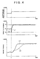
- FIG. 4 is a graph showing the change over time in the accelerator pedal operation amount, the change over time in the throttle opening and the change over time in the engine torque that are obtained when a temporary throttle closing control is executed.
- FIG. 5 is a flowchart showing a throttle valve control operation according to the second embodiment.
- FIG. 6 is a graph showing the change over time in the accelerator pedal operation amount, the change over time in the throttle opening and the change over time in the engine torque that are obtained when a throttle opening dividing control is executed.
- FIG. 7 is a view for explaining a modification of the throttle opening dividing control.
- FIG. 8 is a flowchart showing an ignition timing control operation according to the third embodiment.
- FIG. 9 is a graph showing the change over time in the accelerator pedal operation amount, the change over time in the engine torque, the change over time in the throttle opening, and the change over time in ignition timing that are obtained when an ignition timing retard control is executed.
- FIG. 10 is a view illustrating an example of the relation between the torque gradient difference and the ignition timing retard amount.
- FIG. 11 is a view illustrating an example of the relation between the intake pressure difference and the torque gradient.
- FIG. 12 is a view illustrating an example of the relation between the rate of acceleration G in the longitudinal direction and the torque gradient.
- FIG. 1 shows an internal combustion engine in which a control device according to a first embodiment of the present invention is incorporated.
- the internal combustion engine (which may be hereinafter referred to as “engine”) 1 shown in FIG. 1 is an engine mounted in a vehicle as a driving power source and has a plurality of cylinders 2 . Although only one of the cylinders 2 is shown in FIG. 1 , the other cylinders 2 have the same configuration.
- a piston 3 is reciprocably received in each cylinder 2 , and the piston 3 is connected to a crankshaft (not shown) via a connecting rod 4 .
- a combustion chamber 5 is formed between the upper end of the cylinder 2 and the top of the piston 3 , and an intake passage 6 and an exhaust passage 7 are connected to the combustion chamber 5 .
- a spark plug 10 which serves as an ignition means, is provided generally at the center of the upper end of the combustion chamber 5 , and an fuel injector 11 for injecting fuel into the cylinder 2 is provided on the outer side of the intake valves 8 . That is, the engine 1 is a spark ignition internal combustion engine.
- An airflow meter 12 for outputting a signal corresponding to the amount of intake air, a throttle valve 13 for adjusting the amount of intake air, and an intake pressure sensor 14 as intake pressure acquisition means for outputting a signal corresponding to the intake pressure are provided in the intake passage 6 .
- the throttle valve 13 may be an electronically controlled throttle valve, which can be adjusted to a designated opening by an actuator 13 a .
- An exhaust gas purification catalyst 15 is provided in the exhaust passage 7 .
- As the exhaust gas purification catalyst 15 a three-way catalyst, occlusion-reduction type NOx catalyst may be used.
- the operating conditions of the engine 1 are controlled by an engine control unit (which may be hereinafter referred to as “ECU”) 20 .
- the ECU 20 is constituted as a computer unit including a microprocessor and peripheral devices necessary for its operation such as RAM and ROM.
- Sensors that detect the operating conditions of the engine 1 such as a crank angle sensor 21 that outputs a signal indicating the engine rotational speed; an accelerator operation amount sensor 22 that outputs signals indicating the operation amount of the accelerator pedal 16 and a change thereof, respectively; a G-sensor 23 , which functions as acceleration rate detection means, that outputs a signal indicating the rate of acceleration G in the longitudinal direction of the vehicle and a signal indicating the rate of acceleration in the vertical direction of the vehicle; the airflow meters 12 , the intake pressure sensors 14 and so on are connected to the ECU 20 .
- the ECU 20 detects the operating conditions of the engine 1 with reference to output signals from these sensors and controls the ignition timing of each spark plug 10 , the opening of the throttle valves 12 (throttle opening) and so on in order to achieve target operating conditions.
- the ECU 20 executes a predetermined control to control the opening of the throttle valves 12 during acceleration of the engine 1 so that the torque gradient during the acceleration reaches a predetermined target value.
- the torque gradient during acceleration is large, the torque of the engine 1 increases rapidly, in other words, the torque shows a sharp increase, but then significant acceleration shock is likely to occur.
- the torque gradient during acceleration is small, no acceleration shock occurs, but the torque of the engine 1 increases slowly, in other words, the torque shows a gentle increase.
- the ECU 20 executes a throttle valve control operation shown in FIG. 2 to achieve a sharp torque rise and prevent an acceleration shock during acceleration of the engine 1 .
- the control operation shown in FIG. 2 is is executed a predetermined intervals while the engine 1 is running. Because the ECU 20 executes the throttle valve control operation shown in FIG. 2 , the ECU 20 functions as the operation control means of the present invention.
- the ECU 20 first acquires the operating conditions of the engine 1 in step S 11 .
- the ECU 20 acquires engine operating conditions such as, for example, the rotational speed, load, torque, intake air amount, intake pressure and ignition timing of the engine 1 .
- the load of the engine 1 may be calculated based on, for example, the intake air amount. Because the torque of the engine 1 may be correlated with the rotational speed, load, intake pressure, ignition timing and so on of the engine 1 , it may be calculated based on any of these parameters.
- the load and torque of the engine 1 may be calculated by a known method and hence detailed description of the method is omitted.
- the ECU 20 performs this process to acquire the torque of the engine 1 , the ECU 20 functions as the torque acquisition means of the present invention.
- the ECU 20 determines whether the accelerator pedal 16 is being operated to make a request for acceleration of the engine 1 . If it is determined that there is no request for acceleration of the engine 1 , the current control operation is terminated.
- step S 13 the ECU 20 sets a target opening Te for the throttle valves 13 at the end of the acceleration, based on the operating amount of the accelerator pedal 16 and the opening of the throttle valves 13 when the request for acceleration is made. Because the ECU 20 performs this process, the ECU 20 functions as the target opening setting means of the present invention.
- step S 14 the ECU 20 predicts a torque gradient that will be obtained when the requested acceleration is carried out. The prediction of the torque gradient may be carried out with reference to a map shown in FIG. 3 , for example. FIG.
- FIG. 3 shows an example of the relation among the torque of the engine 1 before acceleration (pre-acceleration torque), the operating amount of the accelerator pedal 16 and the torque gradient during acceleration.
- pre-acceleration torque the torque of the engine 1 before acceleration
- the operating amount of the accelerator pedal 16 the torque gradient during acceleration.
- the relation shown in FIG. 3 is calculated or determined empirically and stored as a map in the ROM of the ECU 20 . Because the ECU 20 performs this process, the ECU 20 functions as the torque gradient prediction means of the present invention.
- the ECU 20 determines whether the predicted torque gradient during acceleration is equal to or below a preset predetermined permissible value.
- the predetermined permissible value is set as a reference value to determine whether the acceleration shock which is expected to occur during acceleration will be within a permissible range determined in view of the effect on the driver.
- the predetermined permissible value is set to such a torque gradient that if the torque gradient during acceleration is greater than the predetermined permissible value, an acceleration shock that exceeds the permissible range will occur. If it is determined that the predicted torque gradient during acceleration is greater than the predetermined permissible value, the current control operation is terminated.
- step S 16 the operation proceeds to step S 16 , in which the ECU 20 executes a temporary throttle closing control in which the throttle valves 13 is temporarily controlled to the close side before it is controlled to the open side. Then, the current control operation is terminated.
- FIG. 4 shows, from top to bottom, the change over time in the accelerator pedal opening, the change over time in the throttle opening, and the change over time in the torque of the engine 1 .
- a curve L 1 shows an example of the change over time in the throttle opening brought about by the temporary throttle closing control
- a curve L 2 shows an example of the change over time in the torque brought about by the temporary throttle closing control.
- a curve L 2 in FIG. 4 also represents an example of the change over time in the torque that is obtained when the torque gradient is equal to the predetermined permissible value.
- the ECU 20 predicts a torque gradient. Because the torque gradient to be predicted at this time is a torque gradient that will be achieved without a temporary throttle closing control, the curve LA shown in FIG. 4 is predicted. Because the predicted curve L 4 lies below the curve L 2 , which expresses the change over time in the torque that is obtained when the torque gradient is equal to the predetermined permissible value, it is determined that the predicted torque gradient is equal to or below the predetermined value and the ECU 20 executes the temporary throttle closing control.
- the opening amount of the throttle valves 13 is temporarily reduced from a pre-acceleration opening amount Ts to a predetermined minimum opening amount Ta and then controlled to increase until the throttle opening amount reaches a target throttle opening amount Te.
- the minimum opening Ta the throttle opening that is set when the engine 1 is idling (idle opening amount) is selected.
- the minimum opening Ta for the temporary throttle closing control is not limited to the idle opening amount.
- the minimum throttle opening amount Ta may be set based on the difference between the predicted torque gradient and a predetermined permissible value (which may be hereinafter referred to as “torque gradient difference”).
- torque gradient difference a predetermined permissible value
- the minimum throttle opening amount Ta is set to such a value that the torque gradient may be adjusted to the predetermined permissible value when the opening amount of the throttle valves 13 is increased from the minimum throttle opening amount Ta to the target throttle opening amount Te.
- the relation between the torque gradient difference and the minimum throttle opening amount Ta may be calculated or determined empirically and then stored as a map in the ROM of the ECU 20 , and a minimum throttle opening amount Ta may be set with reference to the map.
- the ECU 20 functions as the minimum opening setting means of the present invention. Because the operation of the throttle valves 13 is controlled to adjust the intake air amount in order to control the torque of the engine 1 in the first embodiment, the intake air amount serves as the parameter of the present invention, and the throttle valves 13 functions as the parameter adjusting means of the present invention.
- FIG. 5 shows a throttle valve control operation that is executed by the ECU 20 in the second embodiment. The control is also executed at predetermined intervals while the engine 1 is running.
- the same steps as those in FIG. 2 are designated by the same reference numerals in FIG. 5 and their description is omitted.
- step S 21 the ECU 20 determines whether the predicted torque gradient during acceleration is greater than a predetermined permissible value.
- the predetermined permissible value is the same as that used in step S 15 of FIG. 2 . If it is determined that the predicted torque gradient during acceleration is not greater than the predetermined permissible value, the current control operation is terminated.
- step S 22 the operation proceeds to step S 22 , in which the ECU 20 executes a throttle opening dividing control in which the opening of the throttle valves 13 is changed from the pre-acceleration throttle opening amount Ts to a predetermined intermediate throttle opening amount Tc and temporarily held at the opening and then changed from the intermediate opening Tc to the target opening Te during acceleration of the engine 1 . Then, the current control operation is terminated.
- the predetermined intermediate throttle opening amount Tc is set to an opening amount between the pre-acceleration throttle opening amount Ts and the target throttle opening amount Te and such an opening amount that the torque gradient that may be obtained when the throttle opening is changed from the pre-acceleration throttle opening amount Ts to the intermediate throttle opening amount Tc will be smaller than a predetermined value and the torque gradient that may be obtained when the throttle opening amount is changed from the intermediate throttle opening amount Tc to the target throttle opening amount Te will be smaller than a predetermined value.
- Such an intermediate throttle opening amount Tc has a correlation with the torque gradient difference, and the intermediate throttle opening amount Tc is set to a smaller value, that is, a value closer to the pre-acceleration throttle opening amount Ts as the torque gradient difference increases.
- the relation between the intermediate throttle opening amount Tc and the torque gradient difference may be calculated or determined empirically and stored as a map in the ROM of the ECU 20 and the setting of the intermediate throttle opening amount Tc may be made with reference to the map.
- FIG. 6 shows, from top to bottom, the change over time in the accelerator pedal opening, the change over time in the throttle opening amount, and the change over time in the torque of the engine 1 .
- a curve L 11 shows an example of the change over time in the throttle opening amount brought about by the throttle opening dividing control
- a curve L 12 shows an example of the change over time in the torque brought about by the throttle opening dividing control.
- a curve L 12 in FIG. 6 also represents an example of the change over time in the torque that is obtained when the torque gradient is equal to the predetermined value.
- the ECU 20 predicts a torque gradient. Because the torque gradient to be predicted at this time is a torque gradient that will be achieved without the execution of a throttle opening dividing control, the curve L 14 shown in FIG. 6 is predicted. Because the predicted curve L 4 lies above the curve L 12 expressing the change over time in the torque which is obtained when the torque gradient is equal to the predetermined value, it is determined that the predicted torque gradient is greater than the predetermined value and the ECU 20 executes the throttle opening dividing control.
- the throttle valves 13 are first opened from the pre-acceleration throttle opening amount Ts to the intermediate throttle opening amount Tc and held temporarily at the opening amount as described above. Then, the throttle valves 13 are opened further from the intermediate throttle opening amount Tc to the target throttle opening amount Te.
- a throttle opening dividing control is executed to adjust the torque gradient to a predetermined value when the predicted torque gradient during acceleration is equal to or exceeds a predetermined value, acceleration shock may be prevented. Also, because the change over time in torque during acceleration may be adjusted to follow the curve L 12 shown in FIG. 8 , an unnecessary reduction in torque during acceleration is prevented, resulting in a sharp torque rise. Because the operation of the throttle valves 13 is also controlled to adjust the intake air amount in order to control the torque of the engine 1 in the second embodiment, the intake air amount may be regarded as the parameter of the present invention, and the throttle valves 13 may be regarded as the parameter adjusting means of the present invention.
- the throttle valves are held temporarily at one intermediate throttle opening amount Tc during the throttle opening dividing control in the example shown in FIG. 6 , the throttle valves may be held at two or more throttle opening amounts in the throttle opening dividing control. For example, as shown by a curve L 15 in FIG. 7 , the throttle opening amount may be held temporarily at a first intermediate throttle opening amount Tc 1 and then at a second intermediate throttle opening amount Tc 2 between the first intermediate throttle opening amount Tc 1 and the target throttle opening amount Te before the throttle is opened to the target throttle opening amount Te in the throttle opening dividing control.
- the ECU 20 predicts a torque gradient that will be obtained when the throttle opening amount is changed from the first intermediate throttle opening amount Tc 1 to the target throttle opening amount Te (interim torque gradient) while the throttle opening amount is temporarily held at the first intermediate throttle opening amount Tc 1 , and the throttle opening amount is held temporarily at the second intermediate throttle opening amount Tc 2 if the predicted interim torque gradient is equal to or exceeds a predetermined value. Because an interim torque gradient is predicted and the throttle valves 13 are controlled based on the predicted interim torque gradient in the throttle opening dividing control, the change over time in the torque during acceleration follows the curve L 12 shown in FIG. 7 more reliably. As a result, acceleration shock may be prevented more reliably. Because the ECU 20 predicts an interim torque gradient, the ECU 20 may be regarded as interim torque gradient prediction means of the present invention.
- the torque gradient that is obtained when the throttle opening amount is changed from the second intermediate throttle opening amount Tc 2 to the target throttle opening amount Te may be predicted while the throttle opening is held at the second intermediate throttle opening amount Tc 2 and the throttle opening amount may be held temporarily again at a third intermediate opening amount between the second intermediate throttle opening amount Tc 2 and the target throttle opening amount Te based on the result of the prediction.
- a torque gradient which will be obtained when the throttle opening amount is changed from the current opening to the target throttle opening amount Te may be predicted and the throttle opening amount may be held temporarily again at a third intermediate opening amount between the current throttle opening amount and the target throttle opening amount Te based on the result of the prediction.
- the change over time in the torque during acceleration follows the curve L 12 shown in FIG. 7 much more reliably.
- FIG. 8 shows an ignition timing control operation of the third embodiment that is executed by the ECU 20 at predetermined intervals while the engine 1 is running.
- the same steps as those in FIG. 2 and FIG. 5 are designated by the same reference numerals in FIG. 8 and their description is omitted.
- step S 11 the ECU 20 carries out step S 11 to step S 21 in the same manner as shown in FIG. 5 . If it is determined that the torque gradient during acceleration predicted in step S 21 is not greater than the predetermined permissible value, the current control operation is terminated. If it is determined that the predicted torque gradient during acceleration is greater than the predetermined permissible value, the operation proceeds to step S 31 , in which the ECU 20 executes an ignition timing retard control so that the ignition timing of the spark plugs 10 is retarded during acceleration. Then, the current control operation is terminated.
- FIG. 9 shows, from top to bottom, the change over time in the accelerator operation amount, the change over time in the torque of the engine 1 , the change over time in the throttle opening amount, and the change over time in the ignition timing.
- a curve L 21 shows an example of the change over time in the torque controlled by the ignition timing retard control
- a curve L 22 shows an example of the change over time in the throttle opening amount
- a curve L 23 shows an example of the change over time in the ignition timing brought about by the ignition timing retard control.
- a curve L 21 in FIG. 9 also represents an example of the change over time in the torque that is obtained when the torque gradient is equal to the predetermined value.
- the ECU 20 predicts a torque gradient at time t 22 . Because the torque gradient to be predicted at this time is a torque gradient that is achieved without an ignition timing delaying control, the curve L 24 shown in FIG. 9 is predicted. Because the predicted curve L 24 lies above the curve L 21 expressing the change over time in the torque that is obtained when the torque gradient is equal to the predetermined value, it is determined that the predicted torque gradient is equal to or exceeds the predetermined value, and an ignition timing retard control is started at a time t 23 . In the ignition timing retard control, the ignition timing is retarded in accordance with the torque gradient difference.
- the degree to which the ignition timing is retarded may be set based on a relation between the torque gradient difference and the degree of ignition timing delay shown by a solid line curve L 31 in FIG. 10 .
- a relation as shown by the solid line curve 131 in FIG. 10 may be calculated or determined empirically and stored as a map in the ROM of the ECU 20 in advance.
- the ECU 20 can be regarded as the storage means of the present invention.
- the greater the torque gradient difference the more the ignition timing is retarded.
- the retardation of the ignition timing is at a maximum.
- the ignition timing is gradually advanced to the ignition timing before acceleration, and the ignition timing retard control is completed at a time t 25 when the acceleration is completed.
- the torque during acceleration may be adjusted to follow the curve L 21 in FIG. 9 by retarding the ignition timing in accordance with the torque gradient difference.
- the ignition timing is retarded to reduce the torque output during acceleration when the predicted torque gradient during acceleration is equal to exceeds a predetermined value, an acceleration shock can be prevented. Because the operation of the spark plugs 10 is controlled to adjust the ignition timing in order to control the torque of the engine 1 in the third embodiment, the ignition timing may be regarded as the parameter of the present invention and the spark plugs 10 may be regarded as the parameter adjusting means of the present invention.
- the relation between the torque gradient difference and the retard amount may be corrected based on the rate of acceleration of the vehicle with reference to an output signal from the G-sensor 23 at that time. For example, if the rate of acceleration G in the longitudinal direction of the vehicle increases and the acceleration shock exceeds the permissible range when an ignition timing retard control is executed, it is considered that the degree of the delay in the ignition timing is insufficient. In such a case, the relation shown by the solid line curve L 31 in FIG.
- the ECU 20 corrects the relation shown in FIG. 10 , the ECU 20 can be regarded as the correction means of the present invention.
- the present invention is not limited to the embodiments described above and may be implemented in various ways.
- the internal combustion engine to which the present invention is applied is not limited to a spark ignition internal combustion engine.
- the present invention may be applied to a diesel internal combustion engine.
- the present invention may be also applied to a direct-injection internal combustion engine in which fuel is directly injected into the cylinders and a port-injection internal combustion engine in which fuel is injected into the intake ports.
- the parameter to be controlled to reduce the torque of the engine during acceleration is not limited to the intake air amount or the ignition timing.
- any of various parameters which have an effect on the torque of the engine such as the fuel injection amount, the valve opening or closing timing of the intake valves or the exhaust valves may be controlled to control the torque during acceleration.
- the correction of the control during acceleration based on an output signal from the G-sensor 23 may be made to the temporary throttle closing control or the throttle opening dividing control.
- the minimum throttle opening amount may be corrected based on an output signal from the G-sensor 23 .
- the intermediate throttle opening amount may be corrected based on an output signal from the G-sensor 23 .
- the method for predicting the torque gradient is not limited to this method.
- the intake pressure also has a correlation with the torque gradient.
- intake pressure difference the greater the difference between the intake pressure at the end of acceleration and the intake pressure before the acceleration (which may be hereinafter referred to as “intake pressure difference”) is, the greater the degree of the torque to be increased during the acceleration is, that is, the greater the torque gradient will be.
- a relation between the intake pressure difference and the torque gradient as shown in FIG. 11 may be calculated or determined empirically and stored as a maps in the ROM of the ECU 20 and the torque gradient may be predicted with reference to the map.
- the intake pressure difference may be obtained by estimating the intake pressure at the end of acceleration based on the intake pressure and the operating amount of the accelerator pedal before the acceleration and subtracting the intake pressure before the acceleration from the estimated intake pressure.
- the torque gradient may be predicted based on the rate of acceleration G in the longitudinal direction of the vehicle. For example, because it can be estimated that the engine is already running at a high rotational speed and high output when the rate of acceleration G is already large before further acceleration, it can be predicted that the torque gradient will be small.
- the relation between the rate of acceleration G in the longitudinal direction and the torque gradient may be calculated or determined empirically and stored as a map in the ROM of the ECU 20 and the torque gradient may be predicted based on an output signal from the G-sensor 23 and the map. Because the rate of acceleration G may be changed depending on the gradient of the road on which the vehicle is traveling, the effect of the road should be taken into account.
- the gradient of the road on which the vehicle is traveling is estimated based on the rate of acceleration in the vertical direction of the vehicle and the rate of acceleration G in the longitudinal direction of the vehicle, and the rate of acceleration G is corrected based on the road gradient.
- the torque of the engine before the acceleration may be calculated based on an output signal from the G-sensor 23 .
- the torque of the engine 1 is correlated to the driving force transmitted to the wheels, and the wheel driving force FT may be expressed as Equation (1) using the rate of acceleration G, the weight m of the vehicle, the travel resistance FRL on the vehicle, the gravitational acceleration g and the slope angle ⁇ of the road in the traveling direction of the vehicle. Because the travel resistance FRL may be correlated to the vehicle speed, the travel resistance may be calculated based on the vehicle speed.
- the rate of acceleration G in the longitudinal direction of the vehicle may be obtained based on an output signal from a wheel speed sensor, instead of the G-sensor 23 , that is attached to a wheel to detect the speed of the wheel.
Landscapes
- Engineering & Computer Science (AREA)
- Chemical & Material Sciences (AREA)
- Combustion & Propulsion (AREA)
- Mechanical Engineering (AREA)
- General Engineering & Computer Science (AREA)
- Theoretical Computer Science (AREA)
- Signal Processing (AREA)
- Electrical Control Of Air Or Fuel Supplied To Internal-Combustion Engine (AREA)
- Combined Controls Of Internal Combustion Engines (AREA)
- Control Of Throttle Valves Provided In The Intake System Or In The Exhaust System (AREA)
- Electrical Control Of Ignition Timing (AREA)
Abstract
Description
FT=mG+FRL+mg×sin θ (1)
Claims (19)
Applications Claiming Priority (3)
| Application Number | Priority Date | Filing Date | Title |
|---|---|---|---|
| JP2007059721A JP4780003B2 (en) | 2007-03-09 | 2007-03-09 | Control device for internal combustion engine |
| JP2007-059721 | 2007-03-09 | ||
| PCT/IB2008/000534 WO2008110889A2 (en) | 2007-03-09 | 2008-03-07 | Internal combustion engine torque control |
Publications (2)
| Publication Number | Publication Date |
|---|---|
| US20100108028A1 US20100108028A1 (en) | 2010-05-06 |
| US7937211B2 true US7937211B2 (en) | 2011-05-03 |
Family
ID=39672138
Family Applications (1)
| Application Number | Title | Priority Date | Filing Date |
|---|---|---|---|
| US12/530,517 Expired - Fee Related US7937211B2 (en) | 2007-03-09 | 2008-03-07 | Internal combustion engine torque control |
Country Status (5)
| Country | Link |
|---|---|
| US (1) | US7937211B2 (en) |
| JP (1) | JP4780003B2 (en) |
| CN (1) | CN101631944B (en) |
| DE (1) | DE112008000631B4 (en) |
| WO (1) | WO2008110889A2 (en) |
Cited By (5)
| Publication number | Priority date | Publication date | Assignee | Title |
|---|---|---|---|---|
| US20100241335A1 (en) * | 2007-05-10 | 2010-09-23 | Toyota Jidosha Kabushiki Kaisha | Torque control apparatus and control method for vehicle driving unit |
| US20110125390A1 (en) * | 2009-11-20 | 2011-05-26 | Cummins Inc. | Driveline system impact reverberation reduction |
| US8068944B2 (en) * | 2007-05-16 | 2011-11-29 | Toyota Jidosha Kabushiki Kaisha | Control apparatus for internal combustion engine |
| US20130003778A1 (en) * | 2011-06-28 | 2013-01-03 | GM Global Technology Operations LLC | Method for evaluating an exhaust gas temperature in a exhaust pipe of an internal combustion engine |
| US10300919B2 (en) * | 2014-05-30 | 2019-05-28 | Scania Cv Ab | Torque control of a vehicle powertrain based on a time derivative for a dynamic torque |
Families Citing this family (12)
| Publication number | Priority date | Publication date | Assignee | Title |
|---|---|---|---|---|
| JP4301323B2 (en) * | 2007-05-14 | 2009-07-22 | トヨタ自動車株式会社 | Control device for internal combustion engine |
| JP5918976B2 (en) * | 2011-11-10 | 2016-05-18 | 富士重工業株式会社 | Output control device |
| JP6039981B2 (en) * | 2012-09-25 | 2016-12-07 | 株式会社ケーヒン | Engine control device |
| DE102014211160A1 (en) * | 2014-06-11 | 2015-12-17 | Volkswagen Aktiengesellschaft | Method and control unit for carrying out a gas exchange in a cylinder of an internal combustion engine and internal combustion engine with such a control unit |
| CN104696133B (en) * | 2015-03-05 | 2017-04-12 | 北京博曼迪汽车科技有限公司 | Ignition advance angle control method, ignition advance angle controller and engine |
| US20170122244A1 (en) * | 2015-10-28 | 2017-05-04 | Toyota Motor Engineering & Manufacturing North America, Inc. | Vehicles and methods for controlling internal combustion engine rotational speeds |
| US11167745B2 (en) * | 2018-04-19 | 2021-11-09 | Toyota Jidosha Kabushiki Kaisha | Control system of hybrid vehicle |
| US10550786B1 (en) | 2018-10-02 | 2020-02-04 | GM Global Technology Operations LLC | Predictive torque management for powertrain having continuous actuators and multiple discrete modes |
| US11255282B2 (en) * | 2019-02-15 | 2022-02-22 | Toyota Jidosha Kabushiki Kaisha | State detection system for internal combustion engine, data analysis device, and vehicle |
| CN111828180B (en) * | 2020-07-14 | 2022-11-15 | 中国第一汽车股份有限公司 | Control method for air inlet turning plate, vehicle and storage medium |
| CN112177803B (en) * | 2020-08-26 | 2021-07-23 | 湖北三江航天红林探控有限公司 | Time-sharing ignition control method and system based on air pressure prediction |
| CN113246984B (en) * | 2021-06-17 | 2022-09-09 | 宝能(广州)汽车研究院有限公司 | Vehicle control method and vehicle control device |
Citations (8)
| Publication number | Priority date | Publication date | Assignee | Title |
|---|---|---|---|---|
| JPH05321803A (en) | 1992-05-22 | 1993-12-07 | Toyota Motor Corp | Ignition timing controller of internal combustion engine |
| EP1028242A2 (en) | 1999-02-11 | 2000-08-16 | Robert Bosch Gmbh | Method and apparatus for damping vibration type vehicle movements |
| US6202630B1 (en) | 1999-07-13 | 2001-03-20 | Daimlerchrysler Corporation | Open throttle torque control |
| DE10119724A1 (en) | 2001-04-21 | 2003-02-20 | Daimler Chrysler Ag | Controller preventing impulsive loading in vehicle transmission system, takes up drive train slack before applying high torque demanded |
| US6631319B1 (en) * | 1999-06-22 | 2003-10-07 | Robert Bosch Gmbh | Method and device for controlling the drive unit of a vehicle |
| US20040107034A1 (en) | 2002-08-06 | 2004-06-03 | Kazuhide Togai | Output power controlling apparatus and method for internal combustion engine |
| US20100100263A1 (en) * | 2006-11-24 | 2010-04-22 | Toyota Jidosha Kabushiki Kaisha | Vehicle and driving system for vehicle installation |
| US20100241335A1 (en) * | 2007-05-10 | 2010-09-23 | Toyota Jidosha Kabushiki Kaisha | Torque control apparatus and control method for vehicle driving unit |
Family Cites Families (9)
| Publication number | Priority date | Publication date | Assignee | Title |
|---|---|---|---|---|
| DE3814822A1 (en) * | 1987-05-14 | 1988-11-24 | Volkswagen Ag | Method and device for preventing disruptive vibrations of an internal combustion engine functioning with fuel injection |
| JPH0627516B2 (en) * | 1988-01-29 | 1994-04-13 | マツダ株式会社 | Engine controller |
| JPH0579371A (en) * | 1991-09-18 | 1993-03-30 | Hitachi Ltd | Driving force control device |
| JPH1089120A (en) * | 1996-09-19 | 1998-04-07 | Toyota Motor Corp | Control device for output of internal combustion engine |
| DE19838454C1 (en) * | 1998-08-25 | 2000-03-16 | Daimler Chrysler Ag | Process for reducing load change shock in motor vehicles |
| KR100579234B1 (en) * | 2003-09-09 | 2006-05-11 | 현대자동차주식회사 | Torque control method of internal combustion engine |
| JP2006070751A (en) * | 2004-08-31 | 2006-03-16 | Denso Corp | Control device of internal combustion engine |
| JP4453521B2 (en) * | 2004-11-08 | 2010-04-21 | トヨタ自動車株式会社 | Vehicle control device |
| JP2006246987A (en) * | 2005-03-09 | 2006-09-21 | Fuji Kiko Co Ltd | Car sheet reclining device and its production method |
-
2007
- 2007-03-09 JP JP2007059721A patent/JP4780003B2/en not_active Expired - Fee Related
-
2008
- 2008-03-07 CN CN2008800077326A patent/CN101631944B/en not_active Expired - Fee Related
- 2008-03-07 US US12/530,517 patent/US7937211B2/en not_active Expired - Fee Related
- 2008-03-07 WO PCT/IB2008/000534 patent/WO2008110889A2/en active Application Filing
- 2008-03-07 DE DE112008000631.8T patent/DE112008000631B4/en not_active Expired - Fee Related
Patent Citations (8)
| Publication number | Priority date | Publication date | Assignee | Title |
|---|---|---|---|---|
| JPH05321803A (en) | 1992-05-22 | 1993-12-07 | Toyota Motor Corp | Ignition timing controller of internal combustion engine |
| EP1028242A2 (en) | 1999-02-11 | 2000-08-16 | Robert Bosch Gmbh | Method and apparatus for damping vibration type vehicle movements |
| US6631319B1 (en) * | 1999-06-22 | 2003-10-07 | Robert Bosch Gmbh | Method and device for controlling the drive unit of a vehicle |
| US6202630B1 (en) | 1999-07-13 | 2001-03-20 | Daimlerchrysler Corporation | Open throttle torque control |
| DE10119724A1 (en) | 2001-04-21 | 2003-02-20 | Daimler Chrysler Ag | Controller preventing impulsive loading in vehicle transmission system, takes up drive train slack before applying high torque demanded |
| US20040107034A1 (en) | 2002-08-06 | 2004-06-03 | Kazuhide Togai | Output power controlling apparatus and method for internal combustion engine |
| US20100100263A1 (en) * | 2006-11-24 | 2010-04-22 | Toyota Jidosha Kabushiki Kaisha | Vehicle and driving system for vehicle installation |
| US20100241335A1 (en) * | 2007-05-10 | 2010-09-23 | Toyota Jidosha Kabushiki Kaisha | Torque control apparatus and control method for vehicle driving unit |
Cited By (7)
| Publication number | Priority date | Publication date | Assignee | Title |
|---|---|---|---|---|
| US20100241335A1 (en) * | 2007-05-10 | 2010-09-23 | Toyota Jidosha Kabushiki Kaisha | Torque control apparatus and control method for vehicle driving unit |
| US8442742B2 (en) * | 2007-05-10 | 2013-05-14 | Toyota Jidosha Kabushiki Kaisha | Torque control apparatus and control method for vehicle driving unit |
| US8068944B2 (en) * | 2007-05-16 | 2011-11-29 | Toyota Jidosha Kabushiki Kaisha | Control apparatus for internal combustion engine |
| US20110125390A1 (en) * | 2009-11-20 | 2011-05-26 | Cummins Inc. | Driveline system impact reverberation reduction |
| US8615353B2 (en) * | 2009-11-20 | 2013-12-24 | Cummins Inc. | Driveline system impact reverberation reduction |
| US20130003778A1 (en) * | 2011-06-28 | 2013-01-03 | GM Global Technology Operations LLC | Method for evaluating an exhaust gas temperature in a exhaust pipe of an internal combustion engine |
| US10300919B2 (en) * | 2014-05-30 | 2019-05-28 | Scania Cv Ab | Torque control of a vehicle powertrain based on a time derivative for a dynamic torque |
Also Published As
| Publication number | Publication date |
|---|---|
| WO2008110889A3 (en) | 2008-10-30 |
| JP4780003B2 (en) | 2011-09-28 |
| WO2008110889A2 (en) | 2008-09-18 |
| WO2008110889A8 (en) | 2009-09-17 |
| US20100108028A1 (en) | 2010-05-06 |
| JP2008223511A (en) | 2008-09-25 |
| CN101631944A (en) | 2010-01-20 |
| DE112008000631T5 (en) | 2010-01-07 |
| CN101631944B (en) | 2013-03-06 |
| DE112008000631B4 (en) | 2014-02-20 |
Similar Documents
| Publication | Publication Date | Title |
|---|---|---|
| US7937211B2 (en) | Internal combustion engine torque control | |
| US7367310B2 (en) | Controller for compression ignition engine | |
| US7121233B2 (en) | Control apparatus for an internal combustion engine | |
| US20170254278A1 (en) | Engine control device | |
| JP4811304B2 (en) | Automatic stop device for vehicle engine | |
| US7134412B2 (en) | Method for increasing the reproducibility of the start-up during start-stop operation of an internal combustion engine | |
| US6662551B2 (en) | Apparatus for controlling catalyst temperature and method for controlling catalyst temperature | |
| US6564785B2 (en) | Cylinder intake-air quantity calculating apparatus and method for internal combustion engine | |
| JP4379292B2 (en) | Valve characteristic estimation device and control device for internal combustion engine | |
| EP1914413B1 (en) | Device and method for controlling an internal combustion engine | |
| US10465614B2 (en) | Vehicle control device | |
| EP0615066B1 (en) | Controlling device for multi-cylinder internal combustion engine | |
| EP3342659A1 (en) | Vehicle control device | |
| EP2165057B1 (en) | Controller and control method for internal combustion engine | |
| JP6157139B2 (en) | Control device for internal combustion engine | |
| EP3282113B1 (en) | Control device and control method for internal combustion engine | |
| JP6029371B2 (en) | Control device for internal combustion engine | |
| JP4811305B2 (en) | Automatic stop device for vehicle engine | |
| JP5042255B2 (en) | Control device for multi-cylinder spark ignition internal combustion engine | |
| JP2007170198A (en) | Torque control device for internal combustion engine | |
| JP2007127100A (en) | Control device for internal combustion engine | |
| JP2000186581A (en) | Throttle control device for vehicle engine |
Legal Events
| Date | Code | Title | Description |
|---|---|---|---|
| AS | Assignment |
Owner name: TOYOTA JIDOSHA KABUSHIKI KAISHA,JAPAN Free format text: ASSIGNMENT OF ASSIGNORS INTEREST;ASSIGNOR:ASO, KOJI;REEL/FRAME:023217/0681 Effective date: 20090731 Owner name: TOYOTA JIDOSHA KABUSHIKI KAISHA, JAPAN Free format text: ASSIGNMENT OF ASSIGNORS INTEREST;ASSIGNOR:ASO, KOJI;REEL/FRAME:023217/0681 Effective date: 20090731 |
|
| STCF | Information on status: patent grant |
Free format text: PATENTED CASE |
|
| FEPP | Fee payment procedure |
Free format text: PAYOR NUMBER ASSIGNED (ORIGINAL EVENT CODE: ASPN); ENTITY STATUS OF PATENT OWNER: LARGE ENTITY |
|
| FPAY | Fee payment |
Year of fee payment: 4 |
|
| MAFP | Maintenance fee payment |
Free format text: PAYMENT OF MAINTENANCE FEE, 8TH YEAR, LARGE ENTITY (ORIGINAL EVENT CODE: M1552); ENTITY STATUS OF PATENT OWNER: LARGE ENTITY Year of fee payment: 8 |
|
| FEPP | Fee payment procedure |
Free format text: MAINTENANCE FEE REMINDER MAILED (ORIGINAL EVENT CODE: REM.); ENTITY STATUS OF PATENT OWNER: LARGE ENTITY |
|
| LAPS | Lapse for failure to pay maintenance fees |
Free format text: PATENT EXPIRED FOR FAILURE TO PAY MAINTENANCE FEES (ORIGINAL EVENT CODE: EXP.); ENTITY STATUS OF PATENT OWNER: LARGE ENTITY |
|
| STCH | Information on status: patent discontinuation |
Free format text: PATENT EXPIRED DUE TO NONPAYMENT OF MAINTENANCE FEES UNDER 37 CFR 1.362 |
|
| FP | Lapsed due to failure to pay maintenance fee |
Effective date: 20230503 |