US3079824A - Punching device having a spring biased stripper - Google Patents
Punching device having a spring biased stripper Download PDFInfo
- Publication number
- US3079824A US3079824A US4837660D US3079824A US 3079824 A US3079824 A US 3079824A US 4837660 D US4837660 D US 4837660D US 3079824 A US3079824 A US 3079824A
- Authority
- US
- United States
- Prior art keywords
- punch
- sleeve
- collar
- die
- collars
- Prior art date
- Legal status (The legal status is an assumption and is not a legal conclusion. Google has not performed a legal analysis and makes no representation as to the accuracy of the status listed.)
- Expired - Lifetime
Links
Images
Classifications
-
- B—PERFORMING OPERATIONS; TRANSPORTING
- B21—MECHANICAL METAL-WORKING WITHOUT ESSENTIALLY REMOVING MATERIAL; PUNCHING METAL
- B21D—WORKING OR PROCESSING OF SHEET METAL OR METAL TUBES, RODS OR PROFILES WITHOUT ESSENTIALLY REMOVING MATERIAL; PUNCHING METAL
- B21D28/00—Shaping by press-cutting; Perforating
- B21D28/24—Perforating, i.e. punching holes
-
- Y—GENERAL TAGGING OF NEW TECHNOLOGICAL DEVELOPMENTS; GENERAL TAGGING OF CROSS-SECTIONAL TECHNOLOGIES SPANNING OVER SEVERAL SECTIONS OF THE IPC; TECHNICAL SUBJECTS COVERED BY FORMER USPC CROSS-REFERENCE ART COLLECTIONS [XRACs] AND DIGESTS
- Y10—TECHNICAL SUBJECTS COVERED BY FORMER USPC
- Y10T—TECHNICAL SUBJECTS COVERED BY FORMER US CLASSIFICATION
- Y10T83/00—Cutting
- Y10T83/202—With product handling means
- Y10T83/2092—Means to move, guide, or permit free fall or flight of product
- Y10T83/2096—Means to move product out of contact with tool
- Y10T83/2135—Moving stripper timed with tool stroke
- Y10T83/215—Carried by moving tool element or its support
- Y10T83/2155—Stripper biased against product
- Y10T83/2159—By spring means
-
- Y—GENERAL TAGGING OF NEW TECHNOLOGICAL DEVELOPMENTS; GENERAL TAGGING OF CROSS-SECTIONAL TECHNOLOGIES SPANNING OVER SEVERAL SECTIONS OF THE IPC; TECHNICAL SUBJECTS COVERED BY FORMER USPC CROSS-REFERENCE ART COLLECTIONS [XRACs] AND DIGESTS
- Y10—TECHNICAL SUBJECTS COVERED BY FORMER USPC
- Y10T—TECHNICAL SUBJECTS COVERED BY FORMER US CLASSIFICATION
- Y10T83/00—Cutting
- Y10T83/869—Means to drive or to guide tool
- Y10T83/8776—Constantly urged tool or tool support [e.g., spring biased]
- Y10T83/8785—Through return [noncutting] stroke
-
- Y—GENERAL TAGGING OF NEW TECHNOLOGICAL DEVELOPMENTS; GENERAL TAGGING OF CROSS-SECTIONAL TECHNOLOGIES SPANNING OVER SEVERAL SECTIONS OF THE IPC; TECHNICAL SUBJECTS COVERED BY FORMER USPC CROSS-REFERENCE ART COLLECTIONS [XRACs] AND DIGESTS
- Y10—TECHNICAL SUBJECTS COVERED BY FORMER USPC
- Y10T—TECHNICAL SUBJECTS COVERED BY FORMER US CLASSIFICATION
- Y10T83/00—Cutting
- Y10T83/929—Tool or tool with support
- Y10T83/9411—Cutting couple type
- Y10T83/9423—Punching tool
- Y10T83/9428—Shear-type male tool
-
- Y—GENERAL TAGGING OF NEW TECHNOLOGICAL DEVELOPMENTS; GENERAL TAGGING OF CROSS-SECTIONAL TECHNOLOGIES SPANNING OVER SEVERAL SECTIONS OF THE IPC; TECHNICAL SUBJECTS COVERED BY FORMER USPC CROSS-REFERENCE ART COLLECTIONS [XRACs] AND DIGESTS
- Y10—TECHNICAL SUBJECTS COVERED BY FORMER USPC
- Y10T—TECHNICAL SUBJECTS COVERED BY FORMER US CLASSIFICATION
- Y10T83/00—Cutting
- Y10T83/929—Tool or tool with support
- Y10T83/9457—Joint or connection
- Y10T83/9473—For rectilinearly reciprocating tool
- Y10T83/9476—Tool is single element with continuous cutting edge [e.g., punch, etc.]
Definitions
- punching devices of the unitized or subpress type in which a die is carried in alignment with a punch and guide assembly by a C-shaped rarne or holder.
- lunching devices of this general type are known in the art, and have been provided with punches and dies whose cutting edges are both circular and shaped (nonchcular).
- Devices oi this type have also been provided which include a guide button which has a close sliding t with the working end of the punch.
- rEhe greatest manufacturing economies can be obtained when a single holder may be used for a variety of sizes and shapes of punches and dies, and to this end, it is preferable that the punch and guide assembly thereof be removable for replacement purposes.
- Such assembly typically is slidable in the upper arm or the holder and is maintained a raised or ele ated position by appropriate lifting means. Means have previously been provided for holding such assembly in the holder in a manner that such assembly can reciprocate, but yet not inadvertently escape, for example during handling thereof.
- a further object of the present invention is to provide a punching device of the type described in which there is embodied improved means for retaining the punch and guide assembly thereof.
- Yet another object of the present invention is to provide punch and guide assembly retaining and guiding means which permits use of either a round punch or a shaped punch alternatively in the same assembly.
- a still further object of the present invention is to provide a punch and guide assembly for a punching device of the type described in which a stripper button may be selectively included or omitted in accordance with work requirements.
- FIGURE l is a side elevation view, partly in crosssection, of a punching device equipped with improved punch guidance and retention means provided in accordance with the principles of the present invention
- FIGURE 2 is a top view or the punching device shown in FIGURE l;
- FIGURE 3 is a fragmentary cross-sectional view taken along line IlI--III of FIGURE l;
- FlGURE 4 is an enlarged elevational view of a novel locating pin provided in accordance with the principles of the present invention.
- FlGURE 5 is a perspective view of a novel and stripping guide button employed in the device shown in FIGURE 1.
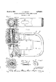
- FIGURE 1t The principles of this invention are particularly useful when embodied in a punching device assembly such as illustrated in FIGURE 1, generally indicated by the numeral 1t).
- the punching device 10 includes a C-shaped frame or holder 11 having an upper arm 12 and a lower arm 13 in which there are respectively supported a punch and guide assembly 14 and an apertured die 15.
- the upper arm 12 has a bore 16 in which the punch and guide assembly 14 is reciprocably supported and guided. To this end, the upper arm 12 is provided with a circular opening 17 which intersects the bore 16 and preferably passes through the holder on both sides thereof as shown so that it is open at both ends to removably receive a locating pin 18 vwhich also is of circular cross-section and which is rotatably disposed in the opening 17 as shown.
- the lower arm 13 has a bore 19 in which the die 15 is received, the die 15 having an aperture 2G aligned with the working end 21 of a punch 22.
- the die 15' especially if the opening 2d is shaped, is provided with a slot 23 which is registerable with a second circular opening 24 disposed in the lower arm 13, and intersecting the bore 19 in the manner that the opening 17 intersects the bore 16 of the upper arm 12.
- Within the opening 24 there is provided a locating pin 25, the inner end of which is received within the slot 23 for lixing the angular position of the die 1S.
- the working end 21 of the punch 22, and also the aperture 2b in the die 15, are of shaped or oval configuration, the oval configuration being used here to be representative of all non-circular shapes of working tips of punches and die apertures.
- a setscrew 26 shown in FIGURE 2 is threadably received through an end or forward face on the lower arm 13.
- the punch and guide assembly includes an elongated sleeve 27, an nnular upper collar 23 slidably disposed at the upper end of the sleeve 27, a lower annular collar 29 disposed about the lower end of the sleeve 27, and a stripping spring 3d extending about the sleeve 27 and acting between the upper collar 2S and the lower collar 29 to bias such collars apart.
- the upper collar 2S has an outer surface 31, and the lower collar 29 has an outer surface 32 which are in direct slidable engagement with the upper arm 12 within the bore 16 thereof.
- the lower collar 29 has a slot 33 in its outer surface 32 which is deiined by a pair of confronting Walls which extend parallel to the direction in which the punch and guide assembly 14 is reciprocable.
- the slot 33 registers with the opening 17 so that the inner end of the locator pin 18 is closely and slidably received within the slot 33.
- the lower collar 29 is further provided with a pair of concentric recesses 34, 3S which open downwardly, the recess 35 being internally slotted to r ceive a snap ring.
- the lower collar 29 is provided with the recess 35 for removably receiving and retaining a guide and/ or stripper button 36 shown in de- ⁇ in place therein by a removable snap ring 38.
- the opening in the guide button 36 has a configuration corresponding to the working end of the punch 2.1, and has a close sliding tit therewith to enable accurate stripping of the workpiece from the working end 21 and for guiding the Same.
- Ihe sleeve 27 is grooved at its ends and receives an-additional pair of snap rings 39, 40 axially outwardly of lshoulders of the collars 28, 29 respectively for limiting the distance apart which the spring 30 can urge such collars, the stripping spring 30 thereby being held in partial compression.
- a locking pin 42 coacts between vthe lower collar 29 and the sleeve 2'7 to preclude axial or angular relative movement therebetween.
- the punch and guide assembly 14 further includes the ⁇ punch 22 which has a head 43 which projects from the -upper collar 28, the body of the punch 22 being directly slidable within the sleeve 27.
- the head 43 of the punch 22 has a peripheral slot which registers with an internal slot in the upper collar 28, there being a manually removable snap ring 44 received therein.
- the side of the collar 28 is cut away-for a few degrees so that the free Vends'of the spring can project horizontally therefrom for manual grasping thereof as shown.
- a lifting spring 45 cooperates with the upper surface of the upper arm 12 and a groove in the outer surface 31 of the upper collar 28 to provide an upward biasing or lifting force to the punch and guide assembly 14.
- the punch and guide assembly 14 is provided with an upwardly directed shoulder 46 carried on the upper collar 28, which shoulder 46 is directed in the direction of the bias fromthe spring 45.
- an elongated stop plate 47 which is disposed and supported on the upper surface of the upper arm 12 of the holder 11. The stop plate 47 overhangs a portion of the bore 1 6 so that its lower surface is engaged by the vshoulder 46 to limit upward movement of the punch and guide assembly 14.
- the stop plate 47 has at one end an aperture 48 and at the other end a laterally directed slot 49, a pair of screws 50, 50 respectively extending through the aperture 48 and the slot 49 to hold the elongated stop plate securely in position.
- the plate 47 may be pivoted about the aperture 48 for removal of the punch and guide assembly 14 as a unit.
- the body of the punch 42 is provided with a recess which receives a Woodruff key 51 which projects therefrom into an elongated slot 52 in the sleeve 27.
- the sleeve 27 is provided with an additional slot 53 best seen in FIGURE 3, as is also the die 15, so that the shaped punch 22 may be selectably positioned in either of two angular positions.
- the pin 1S has a pair of fiat portions 54, which are the portions thereof which snugly slidably tit within the slot 3-3 or" the lower collar 29.
- a pair ofv spaced integral axially directed bifurcations 55, 56 at least one of which is resilient and which have. a free position slightly greater than the 'size ofthe opening 17. For example, I have found that if the dimension across the bifurcations is about .005 inch greater than the diameter of ⁇ the opening 17, the locating vguide or stripper button 36, and die 15 may be rotated to an-angularly spaced position where similar guidance is provided.
- punch, die, and guide button components may be entJ ployed which are adapted to make circular openings.
- the locating pins 1S, 25 may be retracted by means entering the opposite end of the openings 17 and 24 respectively so that the holder will receive a punch and guide assembly which is not provided with a slot 33 and a die which is not provided with a slot 23.
- a punching device comprising in combination: a C-shaped frame having upper and lower arms with axially aligned bores therein; an apertured die removably secured in the bore of the lower of said arms; a punch and guide ⁇ assembly recipro-cably disposed in the bore of the upper of said arms, said assembly including an elongated punchguide sleeve, an upper annular collar slidably surrounding the upper end of said sleeve and a lower annular vcollar surrounding the lower end of said sleeve, a stripping spring means extending about said sleeve and biasing said collars apart, a pair of snap rings each carried by one end of said sleeve and acting against said collars to hold said stripping spring means in partial compression, said collars each having a surface in direct slidable engagement with said upper arm, a punch slidably received within said sleeve and guided thereby and having a head end disposed in and projecting from said upper collar,
- a punching device comprising in combination: a C- shaped frame having upper and lower arms with axially aligned bores therein; an apertured die removably secured in the bore of the lower of said arms; a punch and guide assembly reciprocably disposed in the bore of the upper of said arms, said assembly including an elongated punchguide sleeve, 'an upper annular collar slidably surrounding the upper end of said sleeve and a lower annular collar surrounding the lower end of said sleeve, a stripping spring means extending about said sleeve and biasing said collars apart, a pair of snap rings each carried by one end of said sleeve and acting against said collars to hold said stripping spring means in partial compression, said collars each having a surface in direct slidable engagement with said upper arm, a punch slidably received within said sleeve and having a head end disposed in and projecting from said upper collar, a manually removable snap ring securing said head end to said
- a punching device comprising in combination: a C- shaped frame having upper and lower arms with axially aligned bores therein; an apertured die removably secured in the bore of the lower of said arms; a punch and guide assembly reciprocably disposed in the bore of the upper of said arms, said assembly including an elongated punchguide sleeve, an upper annular collar slidably surrounding the upper end of said sleeve and having a shoulder within the bore of the upper arm directed away from said die, and a lower annular collar surrounding the lower end of said sleeve, stripping spring means extending about said sleeve and biasing said collars apart, a pair of snap rings each carried by one end oi said sleeve and acting against said collars to hold said stripping spring means in partial compression, said collars each having a surface in direct slidable engagement with said upper arm, a punch slidably received within said sleeve and guided thereby and having a end disposed in and projecting from
- a punching device comprising in combination: a C-sha; ed trarne having upper and lower arms with axiaily aligned bores therein; an apertured die removably secured in the bore of ythe lower of said arms; a punch amd guide assembly reciprooably disposed in the bore of Lne up er oi said arms, said assembly including an elongated punch-guide sleeve, an upper annular collar slidably surrounding the upper end of said sleeve land a lower annular collar surrounding the lower end orn said sleeve, stripping spring means extending about said sleeve and biasing said ⁇ collars apart, a pair or snap rings each carried by ⁇ one end of sleeve and acting against said collars to hold said stripping spring means in partial compression, said colims each having an outer surface in direct sl-idahle engagement with said upper arm, a.
- a punching device comprising in combination: a C-shapcd frame having upper and lower arms with axially aligned bores therein; an apertured die removably secured in the bore of the lower of said arms; a punch 'and guide assembly reciprocably disposed in the bore of the upper of said arms, said assembly including an elongated punch-guide sleeve, an upper annular collar slidably surrounding tl e upper end of said sleeve and a lower annular collar surrounding the lower end of said sleeve, stripping spring means extending about said sleeve and biasing said collars apart, a pair of snap rings each carried by one end of said sleeve and acting against said collars to hold said stripping spring means in partial compression, said collars each having an outer surface in direct slidable engagement with said upper arm, a punch slidably received within said sleeve and guided thereby and having a head end disposed in and projecting from said upper collar, a manually removable snap
- a punching device comprising in combination: a G-shaped frame having upper and lower arms with axF ially aligned bores therein; an apertured die removably secured in the bore of .the lower ol Said arms; a punch and guide assembly reciprocably disposed in the bore of the upper of said arms, said ⁇ assembly including an elongated punch-guide sleeve, an upper vannular collar slidably surrounding the upper end of said sleeve and a lower lannular collar surrounding the lower end of said sleeve, stripping spring means extending about said sleeve and biasing Said collars apart, a pair of snap rings each carried by one end of said sleeve and acting against said coll-ars to hold said stripping spring means in pai-tial compression, said collars each having an Outer surface in 'direct sldable engagement with said upper arrn, a punch slidably received wi-thin said sleeve and guided
Landscapes
- Engineering & Computer Science (AREA)
- Mechanical Engineering (AREA)
- Perforating, Stamping-Out Or Severing By Means Other Than Cutting (AREA)
Description
March 5, 1963 A. k. SCHOTT 3,079,824
PUNCHING DEVICE HAVING A SPRING BIASED STRIPPER Filed Aug. 9, 196C) illlllllill S,e7,82 UNCHJNG SE1-J CE H1/1N@ A SPRNG d1-'ASEE STRIPPER Arthnr K. Schott, Kenmore, NDL, assigner to Houdaille industries, inc., Burials, NX., a carpet-ation of Michi- 9, 196%, Ser. No. 48,376 6 Claims. {CL 83-14t3) rlhis invention relates generally to punching devices of the unitized type, and more specically to improved punch guidance and retention means incorporated therein.
Although the principles of the present invention may be included in various punching devices, a particularly useful application is made in punching devices of the unitized or subpress type in which a die is carried in alignment with a punch and guide assembly by a C-shaped rarne or holder. lunching devices of this general type are known in the art, and have been provided with punches and dies whose cutting edges are both circular and shaped (nonchcular). Devices oi this type have also been provided which include a guide button which has a close sliding t with the working end of the punch.
'It is apparent that it is more expensive to provide and operate devices of this type where the punch tip is provided with guidance means than when such means are omitted, and yet when the highest quality of punching is required, it has been found necessary to employ punch tip or working end stripping means. ln the past, this has necessitated the use of two separate devices, one which incorporates the guided tip means, and the other which, for economy reasons, omits the same.
it is also known in the art that shaped punches and dies require indexing or keying to maintain them accurately in alignment so as to preclude any possible relative angular movement.
rEhe greatest manufacturing economies can be obtained when a single holder may be used for a variety of sizes and shapes of punches and dies, and to this end, it is preferable that the punch and guide assembly thereof be removable for replacement purposes. Such assembly typically is slidable in the upper arm or the holder and is maintained a raised or ele ated position by appropriate lifting means. Means have previously been provided for holding such assembly in the holder in a manner that such assembly can reciprocate, but yet not inadvertently escape, for example during handling thereof.
Accordingly, it is an object of the present invention to provide a punching device of the type described which is provided with improved means for guiding and angularly locating the punch and guide assembly thereof.
A further object of the present invention is to provide a punching device of the type described in which there is embodied improved means for retaining the punch and guide assembly thereof.
Yet another object of the present invention is to provide punch and guide assembly retaining and guiding means which permits use of either a round punch or a shaped punch alternatively in the same assembly.
A still further object of the present invention is to provide a punch and guide assembly for a punching device of the type described in which a stripper button may be selectively included or omitted in accordance with work requirements.
Many other advantages, features and additional objects of the present invention will become manifest to those versed in the art upon making reference to the detailed description and the accompanying sheet of drawings in which a preferred structural embodiment incorporating the principles of the present invention is shown by way of illustrative example.
didnt On the drawings:
FIGURE l is a side elevation view, partly in crosssection, of a punching device equipped with improved punch guidance and retention means provided in accordance with the principles of the present invention;
FIGURE 2 is a top view or the punching device shown in FIGURE l;
FIGURE 3 is a fragmentary cross-sectional view taken along line IlI--III of FIGURE l;
FlGURE 4 is an enlarged elevational view of a novel locating pin provided in accordance with the principles of the present invention; and
FlGURE 5 is a perspective view of a novel and stripping guide button employed in the device shown in FIGURE 1.
As shown on the drawings:
The principles of this invention are particularly useful when embodied in a punching device assembly such as illustrated in FIGURE 1, generally indicated by the numeral 1t).
The punching device 10 includes a C-shaped frame or holder 11 having an upper arm 12 and a lower arm 13 in which there are respectively supported a punch and guide assembly 14 and an apertured die 15.
The upper arm 12 has a bore 16 in which the punch and guide assembly 14 is reciprocably supported and guided. To this end, the upper arm 12 is provided with a circular opening 17 which intersects the bore 16 and preferably passes through the holder on both sides thereof as shown so that it is open at both ends to removably receive a locating pin 18 vwhich also is of circular cross-section and which is rotatably disposed in the opening 17 as shown.
The lower arm 13 has a bore 19 in which the die 15 is received, the die 15 having an aperture 2G aligned with the working end 21 of a punch 22. The die 15', especially if the opening 2d is shaped, is provided with a slot 23 which is registerable with a second circular opening 24 disposed in the lower arm 13, and intersecting the bore 19 in the manner that the opening 17 intersects the bore 16 of the upper arm 12. Within the opening 24 there is provided a locating pin 25, the inner end of which is received within the slot 23 for lixing the angular position of the die 1S. As shown in FIGURE 3, the working end 21 of the punch 22, and also the aperture 2b in the die 15, are of shaped or oval configuration, the oval configuration being used here to be representative of all non-circular shapes of working tips of punches and die apertures. To retain the die 15 in position, a setscrew 26 shown in FIGURE 2 is threadably received through an end or forward face on the lower arm 13.
The punch and guide assembly includes an elongated sleeve 27, an nnular upper collar 23 slidably disposed at the upper end of the sleeve 27, a lower annular collar 29 disposed about the lower end of the sleeve 27, and a stripping spring 3d extending about the sleeve 27 and acting between the upper collar 2S and the lower collar 29 to bias such collars apart. The upper collar 2S has an outer surface 31, and the lower collar 29 has an outer surface 32 which are in direct slidable engagement with the upper arm 12 within the bore 16 thereof. The lower collar 29 has a slot 33 in its outer surface 32 which is deiined by a pair of confronting Walls which extend parallel to the direction in which the punch and guide assembly 14 is reciprocable. The slot 33 registers with the opening 17 so that the inner end of the locator pin 18 is closely and slidably received within the slot 33. The lower collar 29 is further provided with a pair of concentric recesses 34, 3S which open downwardly, the recess 35 being internally slotted to r ceive a snap ring. Thus the lower collar 29 is provided with the recess 35 for removably receiving and retaining a guide and/ or stripper button 36 shown in de- `in place therein by a removable snap ring 38. The opening in the guide button 36 has a configuration corresponding to the working end of the punch 2.1, and has a close sliding tit therewith to enable accurate stripping of the workpiece from the working end 21 and for guiding the Same.
Ihe sleeve 27 is grooved at its ends and receives an-additional pair of snap rings 39, 40 axially outwardly of lshoulders of the collars 28, 29 respectively for limiting the distance apart which the spring 30 can urge such collars, the stripping spring 30 thereby being held in partial compression. Y A locking pin 42 coacts between vthe lower collar 29 and the sleeve 2'7 to preclude axial or angular relative movement therebetween. Thus the lower end of the stripping spring 30, the lower collar- 29, and the sleeve 27 are thus slidable as a unit and are guided by the locating pin 18 for such movement with respect tothe holder 11.
' The punch and guide assembly 14 further includes the `punch 22 which has a head 43 which projects from the -upper collar 28, the body of the punch 22 being directly slidable within the sleeve 27. The head 43 of the punch 22 has a peripheral slot which registers with an internal slot in the upper collar 28, there being a manually removable snap ring 44 received therein. The side of the collar 28is cut away-for a few degrees so that the free Vends'of the spring can project horizontally therefrom for manual grasping thereof as shown. When the snap ring 44 is compressed, the, punch 22 and snap ring 44 may be vremoved as a unit since the ring 44 is received to the extent necessary within the head 43. A lifting spring 45 cooperates with the upper surface of the upper arm 12 and a groove in the outer surface 31 of the upper collar 28 to provide an upward biasing or lifting force to the punch and guide assembly 14.
The punch and guide assembly 14 is provided with an upwardly directed shoulder 46 carried on the upper collar 28, which shoulder 46 is directed in the direction of the bias fromthe spring 45. To cooperate therewith in retaining the punch and guide assembly 14 and in holding the lifting spring 45 in partial compression, there is provided an elongated stop plate 47 which is disposed and supported on the upper surface of the upper arm 12 of the holder 11. The stop plate 47 overhangs a portion of the bore 1 6 so that its lower surface is engaged by the vshoulder 46 to limit upward movement of the punch and guide assembly 14. As best seen in FIGURE 2, the stop plate 47 has at one end an aperture 48 and at the other end a laterally directed slot 49, a pair of screws 50, 50 respectively extending through the aperture 48 and the slot 49 to hold the elongated stop plate securely in position. When the screws 50 are loosened, the plate 47 may be pivoted about the aperture 48 for removal of the punch and guide assembly 14 as a unit.
The body of the punch 42 is provided with a recess which receives a Woodruff key 51 which projects therefrom into an elongated slot 52 in the sleeve 27. The sleeve 27 is provided with an additional slot 53 best seen in FIGURE 3, as is also the die 15, so that the shaped punch 22 may be selectably positioned in either of two angular positions.
Referring again to FIGURE 4, it will be noted that the pin 1S has a pair of fiat portions 54, which are the portions thereof which snugly slidably tit within the slot 3-3 or" the lower collar 29. At the other end or" the pin 18, and in the corresponding end of the locating pin 2.5, there is provided a pair ofv spaced integral axially directed bifurcations 55, 56 at least one of which is resilient and which have. a free position slightly greater than the 'size ofthe opening 17. For example, I have found that if the dimension across the bifurcations is about .005 inch greater than the diameter of` the opening 17, the locating vguide or stripper button 36, and die 15 may be rotated to an-angularly spaced position where similar guidance is provided. Further, where another size or conguration is desired, these same components may be easily removed and replaced. Even though such be done, all other components can continue to be used. Further, if less exacting work is required, the guide button 36 may be removed readily by the use of the device. It is also apparent that punch, die, and guide button components may be entJ ployed which are adapted to make circular openings. Furthermore, the locating pins 1S, 25 may be retracted by means entering the opposite end of the openings 17 and 24 respectively so that the holder will receive a punch and guide assembly which is not provided with a slot 33 and a die which is not provided with a slot 23. Thus the instant combination of punch guidance and retention means is especially versatile, so that one assembly may be used in a number of applications.
Although various minor modilications might be suggested by those versed in the art, it should be understood that I wish to embody within the scope of the patent warranted hereon all such embodiments as reasonably and properly come within the scope of my contribution to the art.
I claim as my invention:
1. A punching device comprising in combination: a C-shaped frame having upper and lower arms with axially aligned bores therein; an apertured die removably secured in the bore of the lower of said arms; a punch and guide `assembly recipro-cably disposed in the bore of the upper of said arms, said assembly including an elongated punchguide sleeve, an upper annular collar slidably surrounding the upper end of said sleeve and a lower annular vcollar surrounding the lower end of said sleeve, a stripping spring means extending about said sleeve and biasing said collars apart, a pair of snap rings each carried by one end of said sleeve and acting against said collars to hold said stripping spring means in partial compression, said collars each having a surface in direct slidable engagement with said upper arm, a punch slidably received within said sleeve and guided thereby and having a head end disposed in and projecting from said upper collar, a manually removable snap ring securing said head end to said upper collar, said punch having a working end adapted to cooperate with said die, and said lower collar having a downwardly directed internal recess` defining a downwardly directed annular shoulder within the axial limits of the working end of the punch, said recess being adapted to receive and removably retain a stripper button at said Working-end of said punch; and a lifting spring coacting between said upper arm and said upper collar to bias said assembly away from said die.
2. A punching device comprising in combination: a C- shaped frame having upper and lower arms with axially aligned bores therein; an apertured die removably secured in the bore of the lower of said arms; a punch and guide assembly reciprocably disposed in the bore of the upper of said arms, said assembly including an elongated punchguide sleeve, 'an upper annular collar slidably surrounding the upper end of said sleeve and a lower annular collar surrounding the lower end of said sleeve, a stripping spring means extending about said sleeve and biasing said collars apart, a pair of snap rings each carried by one end of said sleeve and acting against said collars to hold said stripping spring means in partial compression, said collars each having a surface in direct slidable engagement with said upper arm, a punch slidably received within said sleeve and having a head end disposed in and projecting from said upper collar, a manually removable snap ring securing said head end to said upper collar, said punch having a working end adapted to cooperate with said die, said lower collar having a downwardly directed internal recess defining a downwardly directed annular shoulder within the axial limits of the working end of the punch, an annular stripper button received within said recess and having a lit for cooperating with said working end of said punch, and means removably securing said stripper button in said recess; and a lifting spring coacting between said upper arm and said upper collar to bias said assembly away from said die.
3. A punching device comprising in combination: a C- shaped frame having upper and lower arms with axially aligned bores therein; an apertured die removably secured in the bore of the lower of said arms; a punch and guide assembly reciprocably disposed in the bore of the upper of said arms, said assembly including an elongated punchguide sleeve, an upper annular collar slidably surrounding the upper end of said sleeve and having a shoulder within the bore of the upper arm directed away from said die, and a lower annular collar surrounding the lower end of said sleeve, stripping spring means extending about said sleeve and biasing said collars apart, a pair of snap rings each carried by one end oi said sleeve and acting against said collars to hold said stripping spring means in partial compression, said collars each having a surface in direct slidable engagement with said upper arm, a punch slidably received within said sleeve and guided thereby and having a end disposed in and projecting from said upper collar, a manually removable snap ring securing said head end to said upper collar, said punch having a working end adapted to cooperate with said die, and said lower collar having a downwardly directed internal recess defining a downwardly directed annular shoulder within the axial limits of the working end o the punch, said recess being adapted to receive and removably retain a stripper button at said working-end of said punch; an elongated stop plate disposed on the upper surface of the upper of said arms in overhanging relation to the bore thereof for engagement with tiret-mentioned shoui ler, said plate being apen tured at one end and laterally slotted at the other end; a or" screws, one extending through the plate aperture and the other through the plate slot and normally secursaid plate in fixed position to limit upward movement of said first-mentioned shoulder, the plate slot being so arranged that said screws, when each is only partially released, enable pivoting of said plate about the axis of the aperture thereof while said assembly is in said upper bore to facilitate replacement of said assembly; and a lifting spring coacting between said upper arm and said upper collar to bias said assembly away from said die.
4. A punching device comprising in combination: a C-sha; ed trarne having upper and lower arms with axiaily aligned bores therein; an apertured die removably secured in the bore of ythe lower of said arms; a punch amd guide assembly reciprooably disposed in the bore of Lne up er oi said arms, said assembly including an elongated punch-guide sleeve, an upper annular collar slidably surrounding the upper end of said sleeve land a lower annular collar surrounding the lower end orn said sleeve, stripping spring means extending about said sleeve and biasing said `collars apart, a pair or snap rings each carried by `one end of sleeve and acting against said collars to hold said stripping spring means in partial compression, said colims each having an outer surface in direct sl-idahle engagement with said upper arm, a. punch slidably received within said sleeve and guided thereby and having a head end disposed in and projecting from said upper collar, a manually removable snap ring securing said head end to said upper collar, said punch naving a working end adapted to cooperate with die, and said lower collar having a downwardly directed internal rec-ess defining a downwardly directed annular shoulF der within the axial limits of the working end of the punch, Said recess being adapted to receive and removably retain a stripper button at said working end of said punch; said lower collar having means defining a slot opening into said outer surface and extending parallel to the direction of the assembly reciprocation; said upper arm having a circular opening intersecting said bore at said slot; a locating pin disposed in said opening, one end of said pin having a snug slidable tit with said lower collar within said slot, and the other end of said pin having a circular cross Isection defined by a pair of spaced integral axially directed bifurcations both of which are entirely disposed in said opening, at least one of said bifurcations being resilient and having a free position from which it is returnably dellected by said frame to sm'd circular cross section while in said opening for retaining said pin therein against both angular and linear movement; a lifting spring coasting between Said upper arm and said upper collar to bias said assembly away from said die.
5. A punching device comprising in combination: a C-shapcd frame having upper and lower arms with axially aligned bores therein; an apertured die removably secured in the bore of the lower of said arms; a punch 'and guide assembly reciprocably disposed in the bore of the upper of said arms, said assembly including an elongated punch-guide sleeve, an upper annular collar slidably surrounding tl e upper end of said sleeve and a lower annular collar surrounding the lower end of said sleeve, stripping spring means extending about said sleeve and biasing said collars apart, a pair of snap rings each carried by one end of said sleeve and acting against said collars to hold said stripping spring means in partial compression, said collars each having an outer surface in direct slidable engagement with said upper arm, a punch slidably received within said sleeve and guided thereby and having a head end disposed in and projecting from said upper collar, a manually removable snap ring securing said head end to said upper collar, said punch haivng a working end adapted to cooperate with said die, and said lower collar having a downwardly directed internal recess detining a downwardly directed annular shoulder within the axial limits of the working end of the punch, said recess being adapted to receive and removaoly retain a stripper button at said working end of `said punch; said lower collar having means defining a slot opening into said outer surface and extending parallel to the direction of the assembly reciprocation; said upper arm having a circular opening intersecting said bore at said slot; a locating pin having a circular cross section rotatably and slidably disposed in said opening, the inner end of said pin being received within said slot, and having a pair of dat portions snugly and slidably in engagement with opposite walls of said sl and the other end of said pin having a circular cross section de fined by a pair of integral axially directed bifurcations spaced from each other for reception of a rotating tool therebetween and both of which are entirely disposed iu said circular opening, at least one of said bifurcations being resilient and having a free position from which it is returnably deflected by said upper arm to said circular cross section while in said opening for retaining said pin therein against both angular and linear movement; and a lifting spring coacting between said upper arm and said upper collar to bias said assembly away from said die.
6. A punching device comprising in combination: a G-shaped frame having upper and lower arms with axF ially aligned bores therein; an apertured die removably secured in the bore of .the lower ol Said arms; a punch and guide assembly reciprocably disposed in the bore of the upper of said arms, said `assembly including an elongated punch-guide sleeve, an upper vannular collar slidably surrounding the upper end of said sleeve and a lower lannular collar surrounding the lower end of said sleeve, stripping spring means extending about said sleeve and biasing Said collars apart, a pair of snap rings each carried by one end of said sleeve and acting against said coll-ars to hold said stripping spring means in pai-tial compression, said collars each having an Outer surface in 'direct sldable engagement with said upper arrn, a punch slidably received wi-thin said sleeve and guided thereby and having a head end disposed in and projecting from said upper collar, a manually removable snap ring securing said head end to said upper collar, said punch having a working end adapted lto cooperate with said die, and said lower collar having a downwardly directed internal recess defining a downwardly directed annular shoulder within Ithe axial limits of the working end of the punch, said recess being yadapted 'to receive and removably retain .a stripper button at said working end of said punch; at least one of said assembly yand said die having a slot on its outer surface extending parallel to the direction of the reciprocation of said assembly; said frame 'having a circular opening open at both ends, one end of said opening being aligned with said slot; a locating pin disposed in said opening, one end of said pin having a snug it within said slot, and the other end of said pin har/ing a circular cross sec-tion defined by a pair of spaced integral yaxially directed bifurcations both of which are entirely disposed in said opening, at least one of said bifurcations being resilient and having a free posinion from which it is returnably deflected by said frame to said circular cross section While in said openingfor retaining said pin therein against Iboth angular and linear movement; and a lifting spring coacting between said upper arm and said upper collar to bias saidassenibly away from said die. i
References Cited in the iile of this' patent UNITED STATES PATENTS 1,886,177 @airing Nov. 1, 1932 1,939,478 Whistler Dec. 1 2, 1933 1,949,817 Stoneield Mar. 6, 1934 2,017,247 Hodge Oct. 15, 1935 2,320,205 Whales May 25, 1943 2,397,325 Newcomb Mar. 26, 1946 2,882,971 Bennett Apr. 2l, 1959 FOREIGN PATENTS 411,077 Germany Mar. 10, 1925
Claims (1)
1. A PUNCHING DEVICE COMPRISING IN COMBINATION: A C-SHAPED FRAME HAVING UPPER AND LOWER ARMS WITH AXIALLY ALIGNED BORES THEREIN; AN APERTURED DIE REMOVABLY SECURED IN THE BORE OF THE LOWER OF SAID ARMS; A PUNCH AND GUIDE ASSEMBLY RECIPROCABLY DISPOSED IN THE BORE OF THE UPPER OF SAID ARMS, SAID ASSEMBLY INCLUDING AN ELONGATED PUNCHGUIDE SLEEVE, AN UPPER ANNULAR COLLAR SLIDABLY SURROUNDING THE UPPER END OF SAID SLEEVE AND A LOWER ANNULAR COLLAR SURROUNDING THE LOWER END OF SAID SLEEVE, A STRIPPING SPRING MEANS EXTENDING ABOUT SAID SLEEVE AND BIASING SAID COLLARS APART, A PAIR OF SNAP RINGS EACH CARRIED BY ONE END OF SAID SLEEVE AND ACTING AGAINST SAID COLLARS TO HOLD SAID STRIPPING SPRING MEANS IN PARTIAL COMPRESSION, SAID COLLARS EACH HAVING A SURFACE IN DIRECT SLIDABLE ENGAGEMENT WITH SAID UPPER ARM, A PUNCH SLIDABLY RECEIVED WITHIN SAID SLEEVE AND GUIDED THEREBY AND HAVING A HEAD END DISPOSED IN AND PROJECTING FROM SAID UPPER COLLAR, A MANUALLY REMOVABLE SNAP RING SECURING SAID HEAD END TO SAID UPPER COLLAR, SAID PUNCH HAVING A WORKING END ADAPTED TO COOPERATE WITH SAID DIE, AND SAID LOWER COLLAR HAVING A DOWNWARDLY DIRECTED INTERNAL RECESS DEFINING A DOWNWARDLY DIRECTED ANNULAR SHOULDER WITHIN THE AXIAL LIMITS OF THE WORKING END OF THE PUNCH, SAID RECESS BEING ADAPTED TO RECEIVE AND REMOVABLY RETAIN A STRIPPER BUTTON AT SAID WORKING-END OF SAID PUNCH; AND A LIFTING SPRING COACTING BETWEEN SAID UPPER ARM AND SAID UPPER COLLAR TO BIAS SAID ASSEMBLY AWAY FROM SAID DIE.
Priority Applications (1)
| Application Number | Priority Date | Filing Date | Title |
|---|---|---|---|
| US4837660 US3079824A (en) | 1960-08-09 | 1960-08-09 | Punching device having a spring biased stripper |
Applications Claiming Priority (1)
| Application Number | Priority Date | Filing Date | Title |
|---|---|---|---|
| US4837660 US3079824A (en) | 1960-08-09 | 1960-08-09 | Punching device having a spring biased stripper |
Publications (1)
| Publication Number | Publication Date |
|---|---|
| US3079824A true US3079824A (en) | 1963-03-05 |
Family
ID=32467245
Family Applications (1)
| Application Number | Title | Priority Date | Filing Date |
|---|---|---|---|
| US4837660 Expired - Lifetime US3079824A (en) | 1960-08-09 | 1960-08-09 | Punching device having a spring biased stripper |
Country Status (1)
| Country | Link |
|---|---|
| US (1) | US3079824A (en) |
Cited By (42)
| Publication number | Priority date | Publication date | Assignee | Title |
|---|---|---|---|---|
| US3147657A (en) * | 1961-02-24 | 1964-09-08 | Floyd M Williamson | Hydraulically actuated piercing unit |
| US3205742A (en) * | 1963-07-11 | 1965-09-14 | Dro Engineering Company Di | Adjustable pierce unit |
| US3234840A (en) * | 1963-01-15 | 1966-02-15 | Pierce All Mfg Ltd | Punch and die assembly |
| US3429212A (en) * | 1966-08-29 | 1969-02-25 | Unipunch Products | Punch retainer for unitary cutting assembly |
| US3446105A (en) * | 1967-01-24 | 1969-05-27 | Houdaille Industries Inc | Notching unit |
| FR2127331A5 (en) * | 1971-03-04 | 1972-10-13 | Jestin Paul | |
| US3985056A (en) * | 1975-02-17 | 1976-10-12 | Amada Company Limited | Multiple tool holding punching unit |
| US4248111A (en) * | 1979-07-16 | 1981-02-03 | Wilson Tool Company | Punch guide assembly |
| US4556352A (en) * | 1984-08-08 | 1985-12-03 | American Snap Nut Association | Shaft-mounted snap lock assembly |
| US4862782A (en) * | 1988-05-02 | 1989-09-05 | Ernst Robert E | Turret punch press tool assembly |
| US4993295A (en) * | 1988-12-08 | 1991-02-19 | Utica Enterprises, Inc. | Punch stripper |
| US5127293A (en) * | 1990-07-26 | 1992-07-07 | Strippit, Inc. | Stripper plate retaining ring |
| US5271303A (en) * | 1990-07-26 | 1993-12-21 | Strippit, Inc. | Stripper plate retaining ring |
| US5301580A (en) * | 1992-10-07 | 1994-04-12 | Wilson Tool International, Inc. | Locking ring stripper plate assembly |
| US5598635A (en) * | 1993-04-28 | 1997-02-04 | Nitto Kohki Co., Ltd. | Hydraulic puncher |
| US5647256A (en) * | 1995-02-20 | 1997-07-15 | Mate Precision Tooling Inc. | Punch unit including an adjustable punch |
| US5832798A (en) * | 1994-08-10 | 1998-11-10 | Mate Precision Tooling Inc. | Punch unit |
| US5839341A (en) * | 1996-04-12 | 1998-11-24 | Mate Precision Tooling | Punch unit |
| US5878642A (en) * | 1994-09-06 | 1999-03-09 | Utica Enterprises, Inc. | Tool holder |
| US6000139A (en) * | 1998-03-06 | 1999-12-14 | Y & H Industrial Limited | Paper punch |
| US6196103B1 (en) | 1998-08-17 | 2001-03-06 | Mate Precision Tooling Inc. | Punch guide assembly |
| US20030226437A1 (en) * | 2002-06-07 | 2003-12-11 | Rosene Ronald G. | Stripper plate retention system |
| US20040112188A1 (en) * | 2002-12-17 | 2004-06-17 | Masatoshi Oishi | Method for press punching a hole in sheet metal and press die |
| US20060048623A1 (en) * | 2002-12-30 | 2006-03-09 | Albrecht Schneider | Punching tool |
| US20060107721A1 (en) * | 2003-04-30 | 2006-05-25 | Masatoshi Oishi | Punch for punching sheet metal and apparatus for punching sheet metal having the punch |
| US20110094358A1 (en) * | 2008-06-18 | 2011-04-28 | Aramizu Teruo | Punch for punching sheet metal, sheet metal punching apparatus having the punch, and method therefor |
| US20110185874A1 (en) * | 2010-01-29 | 2011-08-04 | Jason Blair | Punch Press |
| US20120000330A1 (en) * | 2010-06-30 | 2012-01-05 | General Electric Company | Apparatuses and methods for cutting porous substrates |
| US20150112243A1 (en) * | 2006-10-25 | 2015-04-23 | Proteus Digital Health, Inc. | Integrated Ingestible Event Marker System with Pharmaceutical Product |
| US9796576B2 (en) | 2013-08-30 | 2017-10-24 | Proteus Digital Health, Inc. | Container with electronically controlled interlock |
| US9962107B2 (en) | 2005-04-28 | 2018-05-08 | Proteus Digital Health, Inc. | Communication system with enhanced partial power source and method of manufacturing same |
| US10084880B2 (en) | 2013-11-04 | 2018-09-25 | Proteus Digital Health, Inc. | Social media networking based on physiologic information |
| US10175376B2 (en) | 2013-03-15 | 2019-01-08 | Proteus Digital Health, Inc. | Metal detector apparatus, system, and method |
| US10187121B2 (en) | 2016-07-22 | 2019-01-22 | Proteus Digital Health, Inc. | Electromagnetic sensing and detection of ingestible event markers |
| US10207093B2 (en) | 2010-04-07 | 2019-02-19 | Proteus Digital Health, Inc. | Miniature ingestible device |
| US10398161B2 (en) | 2014-01-21 | 2019-09-03 | Proteus Digital Heal Th, Inc. | Masticable ingestible product and communication system therefor |
| US10542909B2 (en) | 2005-04-28 | 2020-01-28 | Proteus Digital Health, Inc. | Communication system with partial power source |
| US10588544B2 (en) | 2009-04-28 | 2020-03-17 | Proteus Digital Health, Inc. | Highly reliable ingestible event markers and methods for using the same |
| US11051543B2 (en) | 2015-07-21 | 2021-07-06 | Otsuka Pharmaceutical Co. Ltd. | Alginate on adhesive bilayer laminate film |
| US11149123B2 (en) | 2013-01-29 | 2021-10-19 | Otsuka Pharmaceutical Co., Ltd. | Highly-swellable polymeric films and compositions comprising the same |
| US11504511B2 (en) | 2010-11-22 | 2022-11-22 | Otsuka Pharmaceutical Co., Ltd. | Ingestible device with pharmaceutical product |
| US11529071B2 (en) | 2016-10-26 | 2022-12-20 | Otsuka Pharmaceutical Co., Ltd. | Methods for manufacturing capsules with ingestible event markers |
Citations (8)
| Publication number | Priority date | Publication date | Assignee | Title |
|---|---|---|---|---|
| DE411077C (en) * | 1924-05-16 | 1925-03-10 | Eugen Hecht | Device for coring the antidote of holes in cutting tools u. like |
| US1886177A (en) * | 1931-07-09 | 1932-11-01 | Gairing Tool Company | Boring tool and holder |
| US1939478A (en) * | 1932-11-19 | 1933-12-12 | Whistler & Sons | Die and punch mounting |
| US1949817A (en) * | 1931-10-08 | 1934-03-06 | Logan Co Inc | Roller conveyer |
| US2017247A (en) * | 1934-10-17 | 1935-10-15 | George A Vis | Tool attachment |
| US2320205A (en) * | 1942-03-27 | 1943-05-25 | George F Wales | Apparatus for perforating sheet material |
| US2397325A (en) * | 1944-03-18 | 1946-03-26 | United Aircraft Corp | Locking means for threaded members |
| US2882971A (en) * | 1956-09-20 | 1959-04-21 | George F Wales | Punch construction and guide therefor |
-
1960
- 1960-08-09 US US4837660 patent/US3079824A/en not_active Expired - Lifetime
Patent Citations (8)
| Publication number | Priority date | Publication date | Assignee | Title |
|---|---|---|---|---|
| DE411077C (en) * | 1924-05-16 | 1925-03-10 | Eugen Hecht | Device for coring the antidote of holes in cutting tools u. like |
| US1886177A (en) * | 1931-07-09 | 1932-11-01 | Gairing Tool Company | Boring tool and holder |
| US1949817A (en) * | 1931-10-08 | 1934-03-06 | Logan Co Inc | Roller conveyer |
| US1939478A (en) * | 1932-11-19 | 1933-12-12 | Whistler & Sons | Die and punch mounting |
| US2017247A (en) * | 1934-10-17 | 1935-10-15 | George A Vis | Tool attachment |
| US2320205A (en) * | 1942-03-27 | 1943-05-25 | George F Wales | Apparatus for perforating sheet material |
| US2397325A (en) * | 1944-03-18 | 1946-03-26 | United Aircraft Corp | Locking means for threaded members |
| US2882971A (en) * | 1956-09-20 | 1959-04-21 | George F Wales | Punch construction and guide therefor |
Cited By (62)
| Publication number | Priority date | Publication date | Assignee | Title |
|---|---|---|---|---|
| US3147657A (en) * | 1961-02-24 | 1964-09-08 | Floyd M Williamson | Hydraulically actuated piercing unit |
| US3234840A (en) * | 1963-01-15 | 1966-02-15 | Pierce All Mfg Ltd | Punch and die assembly |
| US3205742A (en) * | 1963-07-11 | 1965-09-14 | Dro Engineering Company Di | Adjustable pierce unit |
| US3429212A (en) * | 1966-08-29 | 1969-02-25 | Unipunch Products | Punch retainer for unitary cutting assembly |
| US3446105A (en) * | 1967-01-24 | 1969-05-27 | Houdaille Industries Inc | Notching unit |
| US3779113A (en) * | 1971-03-04 | 1973-12-18 | P Jestin | Punching unit |
| FR2127331A5 (en) * | 1971-03-04 | 1972-10-13 | Jestin Paul | |
| US3985056A (en) * | 1975-02-17 | 1976-10-12 | Amada Company Limited | Multiple tool holding punching unit |
| US4248111A (en) * | 1979-07-16 | 1981-02-03 | Wilson Tool Company | Punch guide assembly |
| US4556352A (en) * | 1984-08-08 | 1985-12-03 | American Snap Nut Association | Shaft-mounted snap lock assembly |
| WO1986001266A1 (en) * | 1984-08-08 | 1986-02-27 | American Snapnut Associates | Shaft-mounted snap lock assembly and tool |
| US4862782A (en) * | 1988-05-02 | 1989-09-05 | Ernst Robert E | Turret punch press tool assembly |
| US4993295A (en) * | 1988-12-08 | 1991-02-19 | Utica Enterprises, Inc. | Punch stripper |
| US5127293A (en) * | 1990-07-26 | 1992-07-07 | Strippit, Inc. | Stripper plate retaining ring |
| US5271303A (en) * | 1990-07-26 | 1993-12-21 | Strippit, Inc. | Stripper plate retaining ring |
| WO1994007625A1 (en) * | 1992-10-07 | 1994-04-14 | Wilson Tool International, Inc. | Locking ring stripper plate assembly |
| US5301580A (en) * | 1992-10-07 | 1994-04-12 | Wilson Tool International, Inc. | Locking ring stripper plate assembly |
| US5598635A (en) * | 1993-04-28 | 1997-02-04 | Nitto Kohki Co., Ltd. | Hydraulic puncher |
| US5832798A (en) * | 1994-08-10 | 1998-11-10 | Mate Precision Tooling Inc. | Punch unit |
| US6256857B1 (en) * | 1994-09-06 | 2001-07-10 | Utica Enterprises Inc. | Tool holder |
| US5878642A (en) * | 1994-09-06 | 1999-03-09 | Utica Enterprises, Inc. | Tool holder |
| US5647256A (en) * | 1995-02-20 | 1997-07-15 | Mate Precision Tooling Inc. | Punch unit including an adjustable punch |
| US5839341A (en) * | 1996-04-12 | 1998-11-24 | Mate Precision Tooling | Punch unit |
| US6000139A (en) * | 1998-03-06 | 1999-12-14 | Y & H Industrial Limited | Paper punch |
| US6196103B1 (en) | 1998-08-17 | 2001-03-06 | Mate Precision Tooling Inc. | Punch guide assembly |
| US20030226437A1 (en) * | 2002-06-07 | 2003-12-11 | Rosene Ronald G. | Stripper plate retention system |
| US6895849B2 (en) | 2002-06-07 | 2005-05-24 | Wilson Tool International, Inc. | Stripper plate retention system |
| US20040112188A1 (en) * | 2002-12-17 | 2004-06-17 | Masatoshi Oishi | Method for press punching a hole in sheet metal and press die |
| US20110174127A1 (en) * | 2002-12-17 | 2011-07-21 | Ones Co., Ltd. | Method for press punching a hole in sheet metal and press die |
| US8087333B2 (en) * | 2002-12-17 | 2012-01-03 | Ones Co., Ltd. | Method for press punching a hole in sheet metal and press die |
| US20060048623A1 (en) * | 2002-12-30 | 2006-03-09 | Albrecht Schneider | Punching tool |
| US7975587B2 (en) * | 2002-12-30 | 2011-07-12 | Mate Precision Tooling Inc. | Punching tool |
| US20060107721A1 (en) * | 2003-04-30 | 2006-05-25 | Masatoshi Oishi | Punch for punching sheet metal and apparatus for punching sheet metal having the punch |
| US10517507B2 (en) | 2005-04-28 | 2019-12-31 | Proteus Digital Health, Inc. | Communication system with enhanced partial power source and method of manufacturing same |
| US11476952B2 (en) | 2005-04-28 | 2022-10-18 | Otsuka Pharmaceutical Co., Ltd. | Pharma-informatics system |
| US10610128B2 (en) | 2005-04-28 | 2020-04-07 | Proteus Digital Health, Inc. | Pharma-informatics system |
| US9962107B2 (en) | 2005-04-28 | 2018-05-08 | Proteus Digital Health, Inc. | Communication system with enhanced partial power source and method of manufacturing same |
| US10542909B2 (en) | 2005-04-28 | 2020-01-28 | Proteus Digital Health, Inc. | Communication system with partial power source |
| US20150112243A1 (en) * | 2006-10-25 | 2015-04-23 | Proteus Digital Health, Inc. | Integrated Ingestible Event Marker System with Pharmaceutical Product |
| US20110094358A1 (en) * | 2008-06-18 | 2011-04-28 | Aramizu Teruo | Punch for punching sheet metal, sheet metal punching apparatus having the punch, and method therefor |
| US10588544B2 (en) | 2009-04-28 | 2020-03-17 | Proteus Digital Health, Inc. | Highly reliable ingestible event markers and methods for using the same |
| US20110185874A1 (en) * | 2010-01-29 | 2011-08-04 | Jason Blair | Punch Press |
| US11173290B2 (en) | 2010-04-07 | 2021-11-16 | Otsuka Pharmaceutical Co., Ltd. | Miniature ingestible device |
| US10207093B2 (en) | 2010-04-07 | 2019-02-19 | Proteus Digital Health, Inc. | Miniature ingestible device |
| US20210291397A1 (en) * | 2010-06-30 | 2021-09-23 | Qiagen Healthcare Biotechnologies Systems Gmbh | Apparatuses and methods for cutting porous substrates |
| US12145288B2 (en) * | 2010-06-30 | 2024-11-19 | Qiagen Healthcare Biotechnologies Systems Gmbh | Apparatuses and methods for cutting porous substrates |
| US20120000330A1 (en) * | 2010-06-30 | 2012-01-05 | General Electric Company | Apparatuses and methods for cutting porous substrates |
| US9321095B2 (en) * | 2010-06-30 | 2016-04-26 | General Electric Company | Apparatuses and methods for cutting porous substrates |
| US11504511B2 (en) | 2010-11-22 | 2022-11-22 | Otsuka Pharmaceutical Co., Ltd. | Ingestible device with pharmaceutical product |
| US11229378B2 (en) | 2011-07-11 | 2022-01-25 | Otsuka Pharmaceutical Co., Ltd. | Communication system with enhanced partial power source and method of manufacturing same |
| US11149123B2 (en) | 2013-01-29 | 2021-10-19 | Otsuka Pharmaceutical Co., Ltd. | Highly-swellable polymeric films and compositions comprising the same |
| US10175376B2 (en) | 2013-03-15 | 2019-01-08 | Proteus Digital Health, Inc. | Metal detector apparatus, system, and method |
| US9796576B2 (en) | 2013-08-30 | 2017-10-24 | Proteus Digital Health, Inc. | Container with electronically controlled interlock |
| US10421658B2 (en) | 2013-08-30 | 2019-09-24 | Proteus Digital Health, Inc. | Container with electronically controlled interlock |
| US10084880B2 (en) | 2013-11-04 | 2018-09-25 | Proteus Digital Health, Inc. | Social media networking based on physiologic information |
| US11950615B2 (en) | 2014-01-21 | 2024-04-09 | Otsuka Pharmaceutical Co., Ltd. | Masticable ingestible product and communication system therefor |
| US10398161B2 (en) | 2014-01-21 | 2019-09-03 | Proteus Digital Heal Th, Inc. | Masticable ingestible product and communication system therefor |
| US11051543B2 (en) | 2015-07-21 | 2021-07-06 | Otsuka Pharmaceutical Co. Ltd. | Alginate on adhesive bilayer laminate film |
| US10797758B2 (en) | 2016-07-22 | 2020-10-06 | Proteus Digital Health, Inc. | Electromagnetic sensing and detection of ingestible event markers |
| US10187121B2 (en) | 2016-07-22 | 2019-01-22 | Proteus Digital Health, Inc. | Electromagnetic sensing and detection of ingestible event markers |
| US11529071B2 (en) | 2016-10-26 | 2022-12-20 | Otsuka Pharmaceutical Co., Ltd. | Methods for manufacturing capsules with ingestible event markers |
| US11793419B2 (en) | 2016-10-26 | 2023-10-24 | Otsuka Pharmaceutical Co., Ltd. | Methods for manufacturing capsules with ingestible event markers |
Similar Documents
| Publication | Publication Date | Title |
|---|---|---|
| US3079824A (en) | Punching device having a spring biased stripper | |
| KR101201251B1 (en) | Biasing assembly for a punching device | |
| US3125917A (en) | Punch and die assembly having spaced tool positioning plates | |
| US3120143A (en) | Tube notching machine | |
| US4012975A (en) | High speed punching apparatus and tool therefor | |
| GB1262662A (en) | Improvements in or relating to punching tool assemblies | |
| US2882971A (en) | Punch construction and guide therefor | |
| US2778108A (en) | Adjustable gasket cutter | |
| GB907076A (en) | Improvements in or relating to punching dies | |
| US2108619A (en) | Piercing die | |
| US2018366A (en) | Punch | |
| GB1209800A (en) | Spring-stripper for use with punches, dies and the like | |
| US2893488A (en) | Perforating implement having means to align the punch and die | |
| US3926083A (en) | Die set with two-part leader pins | |
| US3110430A (en) | Apparatus for threading wire into a machine | |
| KR102233221B1 (en) | Center ring punching tool | |
| US2431567A (en) | Tool | |
| US2479950A (en) | Device for centralizing strip material | |
| US3230806A (en) | Punch tool alignment apparatus | |
| US1646851A (en) | Punching machine | |
| US2119852A (en) | Adjustable metal thickness scriber | |
| US2246337A (en) | Thread carrier | |
| US3093906A (en) | Drawing board for steel rule dies | |
| US3229559A (en) | Punch and retainer therefor | |
| US2953051A (en) | Perforating implement with stripper sleeve retaining means |