US12336825B2 - Basket style cardiac mapping catheter having a flexible electrode assembly for detection of cardiac rhythm disorders - Google Patents
Basket style cardiac mapping catheter having a flexible electrode assembly for detection of cardiac rhythm disorders Download PDFInfo
- Publication number
- US12336825B2 US12336825B2 US16/270,719 US201916270719A US12336825B2 US 12336825 B2 US12336825 B2 US 12336825B2 US 201916270719 A US201916270719 A US 201916270719A US 12336825 B2 US12336825 B2 US 12336825B2
- Authority
- US
- United States
- Prior art keywords
- splines
- spline
- distal
- portions
- proximal
- Prior art date
- Legal status (The legal status is an assumption and is not a legal conclusion. Google has not performed a legal analysis and makes no representation as to the accuracy of the status listed.)
- Active, expires
Links
Images


Classifications
-
- A—HUMAN NECESSITIES
- A61—MEDICAL OR VETERINARY SCIENCE; HYGIENE
- A61B—DIAGNOSIS; SURGERY; IDENTIFICATION
- A61B18/00—Surgical instruments, devices or methods for transferring non-mechanical forms of energy to or from the body
- A61B18/04—Surgical instruments, devices or methods for transferring non-mechanical forms of energy to or from the body by heating
- A61B18/12—Surgical instruments, devices or methods for transferring non-mechanical forms of energy to or from the body by heating by passing a current through the tissue to be heated, e.g. high-frequency current
- A61B18/14—Probes or electrodes therefor
- A61B18/1492—Probes or electrodes therefor having a flexible, catheter-like structure, e.g. for heart ablation
-
- A—HUMAN NECESSITIES
- A61—MEDICAL OR VETERINARY SCIENCE; HYGIENE
- A61B—DIAGNOSIS; SURGERY; IDENTIFICATION
- A61B5/00—Measuring for diagnostic purposes; Identification of persons
- A61B5/24—Detecting, measuring or recording bioelectric or biomagnetic signals of the body or parts thereof
- A61B5/25—Bioelectric electrodes therefor
- A61B5/279—Bioelectric electrodes therefor specially adapted for particular uses
- A61B5/28—Bioelectric electrodes therefor specially adapted for particular uses for electrocardiography [ECG]
- A61B5/283—Invasive
- A61B5/287—Holders for multiple electrodes, e.g. electrode catheters for electrophysiological study [EPS]
-
- A—HUMAN NECESSITIES
- A61—MEDICAL OR VETERINARY SCIENCE; HYGIENE
- A61B—DIAGNOSIS; SURGERY; IDENTIFICATION
- A61B5/00—Measuring for diagnostic purposes; Identification of persons
- A61B5/68—Arrangements of detecting, measuring or recording means, e.g. sensors, in relation to patient
- A61B5/6846—Arrangements of detecting, measuring or recording means, e.g. sensors, in relation to patient specially adapted to be brought in contact with an internal body part, i.e. invasive
- A61B5/6847—Arrangements of detecting, measuring or recording means, e.g. sensors, in relation to patient specially adapted to be brought in contact with an internal body part, i.e. invasive mounted on an invasive device
- A61B5/6852—Catheters
- A61B5/6858—Catheters with a distal basket, e.g. expandable basket
-
- A—HUMAN NECESSITIES
- A61—MEDICAL OR VETERINARY SCIENCE; HYGIENE
- A61B—DIAGNOSIS; SURGERY; IDENTIFICATION
- A61B5/00—Measuring for diagnostic purposes; Identification of persons
- A61B5/68—Arrangements of detecting, measuring or recording means, e.g. sensors, in relation to patient
- A61B5/6846—Arrangements of detecting, measuring or recording means, e.g. sensors, in relation to patient specially adapted to be brought in contact with an internal body part, i.e. invasive
- A61B5/6847—Arrangements of detecting, measuring or recording means, e.g. sensors, in relation to patient specially adapted to be brought in contact with an internal body part, i.e. invasive mounted on an invasive device
- A61B5/6852—Catheters
- A61B5/6859—Catheters with multiple distal splines
-
- A—HUMAN NECESSITIES
- A61—MEDICAL OR VETERINARY SCIENCE; HYGIENE
- A61B—DIAGNOSIS; SURGERY; IDENTIFICATION
- A61B18/00—Surgical instruments, devices or methods for transferring non-mechanical forms of energy to or from the body
- A61B2018/00053—Mechanical features of the instrument of device
- A61B2018/0016—Energy applicators arranged in a two- or three dimensional array
-
- A—HUMAN NECESSITIES
- A61—MEDICAL OR VETERINARY SCIENCE; HYGIENE
- A61B—DIAGNOSIS; SURGERY; IDENTIFICATION
- A61B18/00—Surgical instruments, devices or methods for transferring non-mechanical forms of energy to or from the body
- A61B2018/00053—Mechanical features of the instrument of device
- A61B2018/00214—Expandable means emitting energy, e.g. by elements carried thereon
- A61B2018/00267—Expandable means emitting energy, e.g. by elements carried thereon having a basket shaped structure
-
- A—HUMAN NECESSITIES
- A61—MEDICAL OR VETERINARY SCIENCE; HYGIENE
- A61B—DIAGNOSIS; SURGERY; IDENTIFICATION
- A61B18/00—Surgical instruments, devices or methods for transferring non-mechanical forms of energy to or from the body
- A61B2018/00315—Surgical instruments, devices or methods for transferring non-mechanical forms of energy to or from the body for treatment of particular body parts
- A61B2018/00345—Vascular system
- A61B2018/00351—Heart
-
- A—HUMAN NECESSITIES
- A61—MEDICAL OR VETERINARY SCIENCE; HYGIENE
- A61B—DIAGNOSIS; SURGERY; IDENTIFICATION
- A61B2562/00—Details of sensors; Constructional details of sensor housings or probes; Accessories for sensors
- A61B2562/16—Details of sensor housings or probes; Details of structural supports for sensors
- A61B2562/17—Comprising radiolucent components
-
- F—MECHANICAL ENGINEERING; LIGHTING; HEATING; WEAPONS; BLASTING
- F04—POSITIVE - DISPLACEMENT MACHINES FOR LIQUIDS; PUMPS FOR LIQUIDS OR ELASTIC FLUIDS
- F04C—ROTARY-PISTON, OR OSCILLATING-PISTON, POSITIVE-DISPLACEMENT MACHINES FOR LIQUIDS; ROTARY-PISTON, OR OSCILLATING-PISTON, POSITIVE-DISPLACEMENT PUMPS
- F04C2270/00—Control; Monitoring or safety arrangements
- F04C2270/04—Force
- F04C2270/042—Force radial
- F04C2270/0421—Controlled or regulated
-
- Y—GENERAL TAGGING OF NEW TECHNOLOGICAL DEVELOPMENTS; GENERAL TAGGING OF CROSS-SECTIONAL TECHNOLOGIES SPANNING OVER SEVERAL SECTIONS OF THE IPC; TECHNICAL SUBJECTS COVERED BY FORMER USPC CROSS-REFERENCE ART COLLECTIONS [XRACs] AND DIGESTS
- Y10—TECHNICAL SUBJECTS COVERED BY FORMER USPC
- Y10T—TECHNICAL SUBJECTS COVERED BY FORMER US CLASSIFICATION
- Y10T29/00—Metal working
- Y10T29/49—Method of mechanical manufacture
- Y10T29/49002—Electrical device making
- Y10T29/49117—Conductor or circuit manufacturing
Definitions
- the present invention is related to the detection of cardiac rhythm disorders by use of basket style cardiac mapping catheters.
- the present invention is further related to cardiac spline baskets having flexible spline tube assemblies with electrodes.
- Electrodes have been positioned along a catheter shaft or basket splines in an attempt to analyze or map the electrical activity within a heart chamber. Mapping typically involves the use or formation external (patches on skin) of electrograms and internal (catheters with electrodes) electrograms.
- a typical electrocardiogram of the cardiac cycle (heartbeat) consists of a P wave, a QRS complex and a T wave.
- the main electrical vector is directed from the SA node, and spreads from the right atrium to the left atrium.
- Atrial depolarization is represented by the P wave on the electrocardiogram.
- the QRS complex reflects the rapid depolarization of the right and left ventricles.
- the T wave represents the repolarization (or recovery) of the ventricles.
- Devices of the prior art often do not provide a complete and stable map of the electrical activity within a heart chamber (recording electrograms).
- electrical activity in certain portions of the right atrium and the left atrium are often difficult to map because of the inability of devices of the prior art to adequately conform to the irregular shape of the atria and their varying shapes during beating of the heart.
- devices of the prior art do not provide dimensionally and/or spatially stable and complete electrograms as the prior art devices often move as the heart beats, thereby moving some or all of the electrodes away from the heart tissue and making the relative position of the electrodes variable to corresponding position of atrial tissue.
- a cardiac mapping catheter that is capable of providing improved and dimensionally and/or spatially stable signals for diagnosis, and more complete coverage of the heart tissue, typically in the form of electrograms.
- a system for sensing multiple local electric voltages from endocardial surface of a heart includes: an elongate tubular member having a lumen, a proximal end and a distal end; a plurality of flexible splines having proximal portions, distal portions and medial portions therein between, wherein the splines comprise an outer surface, an inner surface and two side surfaces; an anchor for securably affixing the proximal portions of the splines, wherein the anchor is securably affixed within the lumen of the elongate tubular member at the distal end of the elongate tubular member; a tip for securably affixing the distal portions of the splines; and a polymeric member including opposed first and second open ends defining an open lumen therein between and an inner member surface and an outer member surface, wherein at least one of the plurality of flexible splines is at least partially disposed within the lumen of the polymeric
- a system for sensing multiple local electric voltages from endocardial surface of a heart includes: an elongate tubular member having a lumen, a proximal end and a distal end; a plurality of flexible splines having proximal portions, distal portions and medial portions therein between, wherein the splines comprise an outer surface, an inner surface and two side surfaces; an anchor for securably affixing the proximal portions of the splines, wherein the anchor is securably affixed within the lumen of the elongate tubular member at the distal end of the elongate tubular member; a tip for securably affixing the distal portions of the splines; and a plurality of polymeric members each having opposed first and second open ends defining an open lumen therein between and an outer surface and an inner surface, wherein each of the plurality of flexible splines is at least partially disposed within the lumen of a different
- FIG. 2 is a side elevational view of the basket style cardiac mapping catheter system of FIG. 1 , according to the present invention.
- FIG. 3 is a schematic view of an introducing catheter of the prior art useful for delivery of the basket style cardiac mapping catheter of FIG. 1 and guide catheter of FIG. 4 into a bodily lumen or organ.
- FIG. 4 is a schematic view of a guide catheter of the prior art useful for delivery of the basket style cardiac mapping catheter of FIG. 1 into a bodily lumen or organ.
- FIG. 5 is an expanded, partial cross-sectional view of a portion of the basket of the system of FIG. 1 showing an expanded basket beyond and outside a hemostat penetrator and/or a guide catheter, according to the present invention.
- FIG. 6 is an expanded, partial cross-sectional view of a portion of the basket of the system of FIG. 1 showing a radially compressed basket within a hemostat penetrator and/or a guide catheter, according to the present invention.
- FIG. 7 is an expanded side view of a portion of the basket of the system of FIG. 1 showing M-shaped, symmetric distal splines, according to the present invention.
- FIG. 9 is a right side view of the M-shaped basket embodiment of FIG. 7 depicting symmetric spline angles, according to the present invention.
- FIG. 10 is a perspective view of the basket of the system of FIG. 1 showing M-shaped, non-symmetric distal splines according to a basket embodiment of the present invention.
- FIG. 12 a side elevational view of one of the splines of the M-shaped basket of FIG. 7 showing proximal spline recurves, according to the present invention.
- FIG. 13 is a perspective view of the spline of FIG. 12 , according to the present invention.
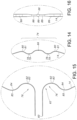
- FIG. 14 is an exploded side view of a distal portion of the spline of FIG. 12 , according to the present invention.
- FIG. 15 is an exploded side view of a proximal portion of the spline of FIG. 12 , according to the present invention.
- FIG. 16 is an exploded right side view of a portion of the distal portion of the spline of FIG. 12 showing a distal thinned portion, according to the present invention.
- FIG. 17 is an expanded side view of another embodiment of a basket of the system of FIG. 1 showing M-shaped distal spline portion and proximal tangential spline curves, according to the present invention.
- FIG. 18 is an expanded side view of another embodiment of a basket of the system of FIG. 1 showing a distal spline D-shaped curve and proximal recurves, according to the present invention.
- FIG. 19 is a perspective view of the spline of FIG. 18 , according to the present invention.
- FIG. 20 is an exploded view of a distal portion of the spline of FIG. 18 , according to the present invention.
- FIG. 21 is an expanded side view of another embodiment of a basket of the system of FIG. 1 showing a distal spline D-shaped curve and proximal tangential spline curves, according to the present invention.
- FIGS. 22 A through 22 D depict thinned side view spline portions, according to the present invention.
- FIG. 23 A depicts side view of a portion of a spline in a neutral position having buckle points, according to the present invention.
- FIG. 23 B depicts side view of a portion of a spline in a deflected position having buckle points, according to the present invention.
- FIG. 24 is a schematic illustration of a spline emerging from a distal tip at an acute angle, according to the present invention.
- FIG. 25 is a schematic illustration of a spline emerging from a distal tip at a substantially perpendicular angle, according to the present invention.
- FIG. 26 A is a front perspective view of a two-part, welded distal tip, according to the present invention.
- FIG. 26 B is a rear perspective view of the distal tip of FIG. 26 A , according to the present invention.
- FIG. 26 C is a front perspective view of a top part of the distal tip of FIG. 26 A , according to the present invention.
- FIG. 26 D is a bottom view of the top part of the distal tip of FIG. 26 A , according to the present invention.
- FIG. 26 E is a front perspective view of a bottom top part of the distal tip of FIG. 26 A , according to the present invention.
- FIG. 26 F is a front perspective view of another embodiment of a two-part, welded distal tip having a rounded or domed upper portion, according to the present invention.
- FIG. 27 A is a front perspective view of an encapsulated, filament wound distal tip, according to the present invention.
- FIG. 27 B is a side elevation view of the distal tip of FIG. 27 A , according to the present invention.
- FIG. 27 C is a rear perspective view of the distal tip of FIG. 27 A , according to the present invention.
- FIG. 27 D is a top perspective view of the filament wrapping of the distal tip of FIG. 27 A , according to the present invention.
- FIG. 27 E is a rear perspective view of the filament wrapping of the distal tip of FIG. 27 A , according to the present invention.
- FIG. 28 A is a side cross-sectional view of another embodiment of a two-part distal tip with half splines, according to the present invention.
- FIG. 28 B is a side cross-sectional view of another embodiment of a two-part distal tip with half splines, according to the present invention.
- FIG. 28 C is a side cross-sectional view of another embodiment of a two-part riveted distal tip with full splines, according to the present invention.
- FIG. 28 D is a top view of aligned splines useful with the distal tip of FIG. 28 C , according to the present invention.
- FIG. 29 is a side elevational view of an encapsulated distal tip, according to the present invention.
- FIG. 30 A is a top view of a membrane distal tip, according to the present invention.
- FIG. 30 B is a partial cross-sectional view of the membrane tip of FIG. 30 A .
- FIG. 31 A is a perspective view of a slotted proximal anchor, according to the present invention.
- FIG. 31 B is a right cross-sectional view of the slotted anchor of FIG. 31 A , according to the present invention.
- FIG. 31 C is an exploded, partial side elevation view of the slotted anchor of FIG. 31 A , according to the present invention.
- FIG. 32 A is a depiction of a proximal portion of a spline having a spline notch, according to the present invention.
- FIG. 32 B is a schematic illustration of an anchor useful for securing the spline of FIG. 32 A , according to the preset invention.
- FIG. 32 C is a partial exploded view of the anchor of FIG. 32 B according to the preset invention.
- FIG. 33 A is an exploded, perspective of the basket of the system of FIG. 1 showing splines with spline tube assemblies, according to the present invention.
- FIGS. 34 A and 34 B are cross-sectional views of a portion of the spline tube assembly of FIG. 33 A , according to the present invention.
- FIG. 34 D is a cross-sectional view of a spline tube assembly with a radiopaque marker, according to the present invention.
- FIG. 34 E is a cross-sectional view of the radiopaque marker of FIG. 34 D , according to the present invention.
- FIG. 34 F is a partial cross-sectional view of a spline tube assembly along the length of the spline tube assembly with a radiopaque marker, according to the present invention.
- FIG. 34 G is a representation of a fluoroscopic image of a side elevation view of a basket with radiopaque marker arrangement to depict spline and electrode locations, according to the present invention.
- FIG. 34 H is a representation of a fluoroscopic image of a perspective view of the basket of FIG. 34 G , according to the present invention.
- FIG. 34 I is a representation of a fluoroscopic image of a rotated side view of the basket of FIG. 34 G , according to the present invention.
- FIG. 35 A is a perspective view of spline tube assembly, according to the present invention.
- FIG. 35 B is another perspective views of spline tube assembly, according to the present invention.
- FIG. 35 C is an exploded perspective view of a spline tube assembly, according to the present invention.
- FIG. 35 D is an exploded, partial cross-sectional view of a proximal portion of the spline tube assembly, according to the present invention.
- FIG. 35 E is an exploded, partial cross-sectional view of a distal portion of the spline tube assembly, according to the present invention.
- FIG. 35 F is an exploded, partial cross-sectional view of a proximal portion of the spline tube assembly showing two flex circuits embedded with a wall of the spline tube assembly, according to the present invention.
- FIG. 35 G is an exploded, partial cross-sectional view of a proximal portion of the spline tube assembly showing one flex circuit embedded with a wall of the spline tube assembly, according to the present invention.
- FIG. 35 H is an exploded, partial cross-sectional view of a portion of the spline tube assembly showing a flex circuit transitioning into an inner lumen of the spline tube assembly, according to the present invention.
- FIG. 36 A is a top view of a flex circuit, according to the present invention.
- FIG. 36 B is a bottom view of the flex circuit of FIG. 36 A , according to the present invention.
- FIG. 36 C is an exploded, right bottom view of a portion of the flex circuit of FIG. 36 A , according to the present invention.
- FIG. 36 D is an exploded, left top view of a portion of the flex circuit of FIG. 36 A , according to the present invention.
- FIG. 36 E is an exploded, left bottom view of a portion of the flex circuit of FIG. 36 A , according to the present invention.
- FIG. 36 F is schematic, cross-sectional view of a portion of the flex circuit of FIG. 36 A , according to the present invention.
- FIG. 37 B is an exploded, right top view of a portion of the flex circuit of FIG. 37 A , according to the present invention.
- FIG. 37 C is an exploded, right bottom view of a portion of the flex circuit of FIG. 37 A , according to the present invention.
- FIG. 38 A is a perspective view of a flex circuit embedded or pressed into a substrate, according to the present invention.
- FIG. 38 B is a partial, side cross-sectional view of the flex circuit of FIG. 38 A , according to the present invention.
- FIG. 39 is a top view of another embodiment of a flex circuit, according to the present invention.
- FIG. 40 A is a partial perspective view of a quad wire assembly with a flex circuit, according to the present invention.
- FIG. 40 B is a partial cross-sectional view of the quad wire assembly with a flex circuit of FIG. 40 A , according to the present invention.
- FIG. 41 A is a partial cut-away perspective view of a catheter shaft with a braided shield and anti-kink beading, according to the present invention.
- FIG. 41 B is a partial cut-away perspective view of another embodiment of a catheter shaft with a braided shield and anti-kink beading, according to the present invention.
- FIG. 42 A is a side elevational view of asymmetric catheter basket FIG. 13 , according to the present invention.
- FIG. 42 B is a front elevational view of a symmetric basket, according to the present invention.
- FIG. 42 C is a front elevational view of an asymmetric basket, according to the present invention.
- FIG. 43 A is an electrogram obtained with the catheter basket system of the present invention.
- FIG. 43 B is an electrogram obtained with a catheter basket system of the prior art.
- FIG. 1 is a perspective view of basket style cardiac mapping system or assembly 10 of the present invention
- FIG. 2 is a side elevation view of the catheter system or assembly 10 of FIG. 1
- the catheter system or assembly 10 consists of three subassemblies: the mapping catheter assembly 8 , including hemostat penetrator assembly 25 , and the extension cable assembly 31 .
- the mapping catheter assembly 8 includes a spline basket 12 , which includes splines 14 with spline tube assemblies (not shown) having electrodes (not shown); a catheter body or shaft 20 ; a hemostat penetrator assembly 25 (comprised of a hemostat penetrator tube 22 and hemostat penetrator handles 24 ); a handle strain relief 26 ; a handle 28 , with an integral connector (not shown).
- the extension cable assembly 31 includes a mating connector 30 and an extension cable 32 ; interrelated as shown.
- the catheter assembly 8 allows ease of operation and precise positioning and control of the basket 12 within a patient. Desirably, connector 30 is round so there is no rotational bias as the basket 12 is disposed within a patient.
- the splines 14 of the spline basket 12 are secured by a distal tip 16 at one end, i.e. the distal end, of the basket 12 , and are further secured by a proximal anchor 18 at an opposed end, i.e. the proximal end, of the basket 12 .
- the anchor 18 is secured to a distal end 20 B of the catheter body 20 and/or within a lumen 20 C of the catheter body 20 of the catheter 8 of the present invention.
- the proximal end 20 A of the catheter body 20 is secured to the strain relief section 26 of the handle 28 .
- a vessel or cavity is punctured with a sharp hollow needle or trocar (not shown).
- a guidewire (not shown) may be then advanced through the lumen of the trocar, and the trocar is withdrawn.
- the introducing catheter 34 may then be passed over the guidewire into the cavity or vessel.
- the introducing catheter 34 includes a hollow introducer lumen 36 .
- the distal end 42 of the introducing catheter 34 is positioned with a vessel or cavity.
- the proximal end 44 of the introducing catheter 34 remains outside of the patient so as to allow a practitioner to control the position of the distal end of the introducing catheter 42 .
- proximal generally refers to a location or direction towards the practitioner.
- distal generally refers to a location or direction away from the practitioner.
- inner, inward and the like generally refer to a direction toward the inside of the basket 12 , for example towards a longitudinal axis L between the distal tip 16 and the proximal anchor 18 .
- outer, outward and the like generally refer to a direction away from the inside of the basket 12 , for example away from a longitudinal axis L between the distal tip 16 and the proximal anchor 18 .
- the guide sheath hemostat valve 50 Upon withdrawal of the hemostat penetrator tube 22 from the guide sheath hemostat valve 50 , the guide sheath hemostat valve with create a leak-proof seal against the outer wall of the catheter body 20 , preventing the loss of blood through the introducer system.
- the splines 14 of the spline basket 12 may be in a compressed state within the lumen 48 of the guide catheter 46 and/or of the lumen of the hemostat penetrator tube 22 .
- the splines 14 are depicted in FIG. 6 as being in a compressed approximate or substantial elongate cylindrical shape. In such a compressed state the effective length of the splines 14 between the distal tip 16 and the proximal anchor 18 are substantially the same.
- Effective spline lengths between the distal tip 16 and the proximal anchor 18 in the expanded basket shape of, for example, FIG. 5 are not so limited and, if desired, may vary as described in further detail below.
- FIG. 7 is an expanded side view of a portion of the basket 12 of the system 8 of FIG. 1 showing M-shaped, symmetric distal splines, according to the present invention.
- the distal basket portion 70 has distal spline portions 66 secured to one and the other by the distal tip 16 .
- the proximal basket portion 68 contains proximal spline portions 62 .
- the proximal spline ends 60 are secured by the proximal anchor 18 (not shown).
- Medial basket portions 72 and medial spline portions 64 are disposed between the respective ends.
- the splines 14 expand or bow outwardly to assume an expanded, non-cylindrical shape, with the basket 12 having a proximal basket portion 68 , a distal basket portion 70 and a medial basket portion 72 there between. While the expanded splines are depicted in a spherical or somewhat spherical orientation, the present invention is not so limited. Indeed, in preferred embodiments of the present invention the expanded splines 14 assume a non-spherical or substantially non-spherical shape, preferably asymmetric.
- FIG. 8 is a perspective view of the basket 12 of FIG. 7 .
- the basket 12 of the present invention may have any useful number of splines.
- FIG. 9 is a right side view of the M-shaped basket embodiment of FIG. 7 depicting symmetric spline angles. As depicted in FIG. 9 , the angles, ⁇ 1 through ⁇ 8 , are all approximately equal at 45°. Such a relationship is a predetermined angular relationship to offer a symmetric or substantially symmetric basket 12 as viewed from a cross-sectional plane of the basket 12 .
- a predetermined angular relationship where the angles, ⁇ 1 through ⁇ 8 , may vary may suitably be used.
- the angles ⁇ 1 and ⁇ 5 are approximately 90°
- the angles ⁇ 2 through ⁇ 4 and ⁇ 6 through ⁇ 8 are approximately 30°.
- Such a non-symmetric angular relationship as depicted in FIGS. 10 and 11 may be useful, if desired, to concentrate a greater number of splines 14 at a particular location within the body, for example the right atrium of the heart.
- FIG. 12 a side elevational view of one of the splines 14 of FIG. 7 showing the M-shaped distal curve 74 of basket 12 at the distal spline portion 66 .
- the spline 14 also contains a proximal recurve 76 at the proximal spline portion 62 .
- the spline 14 is also depicted as being symmetric in its expanded state about a longitudinal axis L, which is determined by the line segment axis from the proximal anchor 18 to the distal tip 16 .
- FIG. 13 is a perspective view of the spline 14 of FIG. 12 , further depicting the spline curvatures at the proximal spline portion 62 and the distal spline portion 66 .
- FIG. 14 is an exploded view of the distal M-shaped spline curve 74 .
- the M-shaped spline curve 74 contains distal incurvate inward bends 78 and excurvate outward bends 80 .
- Bend 78 is described as incurvate and/or inward because an apex 79 is directed towards the interior of the basket 12 .
- Bend 80 is described as excurvate and/or outward because apex 81 is directed away from the interior of the basket 12 .
- Bends 78 are useful in controlling angles from which splines 14 exit from or emerge into the distal tip 16 , i.e., directed toward the exterior of basket 12 .
- the bends 80 turn the splines 14 back in a proximal direction towards the proximal anchor 18 .
- FIG. 15 is an exploded view of the proximal spline portion 62 of the spline 14 of FIG. 12 .
- the proximal spline portions 62 contain proximal recurves 76 .
- the proximal recurves 76 include proximal incurvate bends 82 having apices 83 and proximal excurvate bends 84 having apices 85 .
- the proximal recurves 76 impart several important features to the basket 12 of the present invention.
- the proximal recurves 76 allow for the geometry and flexibility of individual splines 14 to vary at the proximal end 62 which allows the basket 12 to become asymmetric and to better conform to the contours of the right atrium, as described in conjunction with FIG. 42 A below. Further, the proximal recurves 76 allow for better placement of electrodes (not shown) at the proximal atrial tissue. Baskets common in the prior art do not often have good contact with proximal atrial tissue, thereby adversely effecting electrical activity detection thereat.
- the flexibility and geometry of the recurves 76 also permit enhanced electrode-tissue contact for the electrodes placed not only on the proximal spline portions 62 , but also on the medial spline portions 64 and distal spline portions 66 .
- FIG. 16 is an exploded view of the distal spline portion 66 .
- the splines 14 may contain portions of reduced spline widths 88 as compared to normal or non-reduced spline widths 86 .
- the reduced spline widths 88 are depicted as being near the distal spline portion 66 .
- Such reduced widths 88 may increase spline flexibility, as these spline portions are proximal to the distal tip 16 (not shown).
- the distal spline portion 66 may also include an alignment member 89 which, as described further below, is useful for aligning and/or securing the splines 14 within the distal tip 16 (not shown).
- the reduced width portions 88 at the spline distal portions also allows for less force to compress the basket 12 , as depicted in FIG. 6 , during removal of the basket 12 from the patient. Further, the reduced spline widths 88 aid in the basket 12 in achieving the substantially cylindrical shape, as depicted in FIG. 6 .
- the reduced spline widths 88 allows the distal incurvate bends 78 to flex outward or away from the compression force so that the distal spline portions 66 do not retain the inward bends 78 , or simply stated the bends 78 pop outward during radial compression of the basket 12 .
- Another advantage of the distal M-Shaped spline curve 74 is that the distal tip 16 is directed towards the interior of the basket 12 when the basket 12 is deployed or is in its radially expanded state. This feature, if desired, keep the distal tip 16 away from distal heart tissue as the distal spline portions 66 may extend beyond the distal tip 16 in the longitudinal direction of the basket 14 .
- FIG. 17 is another embodiment of the spline 14 of FIG. 12 .
- the spline 14 of FIG. 17 contains proximal tangential curves 90 . While the tangential curve 90 may not offer the same degree of spline flexibility and basket stability as offered by the proximal spline recurve 76 , such a proximal tangential curve 90 may be preferred by some practitioners in certain atrial procedures.
- FIG. 18 is a side elevational view of another spline 14 useful with the present invention.
- the spline 14 in FIG. 18 has a similar proximal spline recurve 76 as the spline 14 of FIG. 12 .
- the spline 14 of FIG. 18 has a D-shaped 92 distal end portion 66 .
- Such a D-shaped distal end 92 is useful with certain embodiments of distal tips 16 that are described below.
- FIG. 19 is a perspective view of the spline of FIG. 18 showing spline curvatures in further detail.
- FIG. 20 is an exploded view of the D-shaped spline portion 92 of FIG. 18 .
- the distal spline portion 66 has substantially flat portions 94 followed by the curved portions 96 .
- the curved portions 96 merge into the normal curvature of the overall basket shape.
- the substantially straight portion 94 are useful with certain distal tip 14 designs and where spline emergence or entrance angles at the distal tip 14 are desired to be about 90°.
- FIG. 21 depicts yet another spline 14 embodiment.
- the spline 14 of FIG. 21 contains D-shaped distal portions 94 , 96 at the distal spline portion 66 and proximal tangential curves 90 at the proximal spline portion 62 .
- the assembly 10 of the present invention may use any combination of the above-described spline geometries.
- Splines 14 may be flattened splines through the body of the spline 14 having a substantial rectangular shape with rounded sides (see, e.g., FIG. 34 C ). Throughout at least a major portion of the splines 14 , the splines 14 may be about 0.013 to about 0.035 inches wide (W 1 ) and about 0.002 to about 0.012 inches thick (T 1 ), as depicted in FIGS. 22 A through 22 D . A preferred width (W 1 ) is about 0.022 inches.
- Spline thickness (T 1 ) may depend on the overall size of the basket 12 with small sized baskets, for example less than 60 mm in nominal diameter, the thickness may range from about 0.002 inches to about 0.010 inches, with 0.004 inches being preferred. For larger size baskets, for example greater than 60 mm in nominal diameter, the thickness may range from about 0.002 inches to about 0.012 inches, with 0.006 inches being preferred. These dimensions are not limiting and represent normal or typical spline width portions 86 and spline thickness portions 98 .
- portions of the splines 14 may have reduced with portions 88 and/or reduced thickness portions 100 .
- these portions 88 , 100 are disposed at distal spline portions 66 near or at the distal tip 16 .
- the present invention is not so limited at these reduced portions 88 , 100 may be present in proximal spline portions 62 and medial spline portions 64 .
- the thinned spline portions 88 , 100 may have a reduction in width and or thickness of several thousands of an inch.
- the thickness (T 2 ) of certain spline portions 100 may be thinned down to several thousands of an inch or to a thickness of about 0.003 inches to 0.004 inches, or less.
- Such thinning of the distal spline segments 66 near the membrane tip 14 reduces stresses during capture of the splines 14 within the guide catheter 34 .
- Low stress is an advantageous feature during collapse for introduction, repositioning and withdrawal of the spline basket.
- the width (W 2 ) of the narrowed spline segments 88 may be narrowed from about 0.013 to 0.035 inches to about 0.008 to 0.014 inches.
- Such thinning aids the splines 14 , when they fold up or collapse into the guide catheter 34 , to overcome their tendency to push themselves apart and avoid them occupying more space in the catheter 34 .
- a low profile catheter system 10 may be provided according to the present invention.
- FIGS. 23 A and 23 B depict a spline portion, such as spline portion 86 , having a buckle point 102 .
- the buckle point 102 may be ground into the spline 14 or formed by any other suitable technique.
- the buckle point 102 is depicted as an inwardly curved notch, but other designs may suitably be used.
- the buckle points 102 provide the splines 14 with curvature inflection points, which provide the basket 12 with improved matching of the contours of the interior of the heart.
- the buckle points 102 may be disposed at any location along the proximal spline portions 62 , the medial spline portions 64 and/or the distal spline portions 66 shown in FIG. 21 . Further, the number or frequency of buckle points 102 may also vary.
- the splines 14 may emerge from the distal tip 16 at any useful emergence angle, ⁇ , with respect to the longitudinal axis L, which is defined by a line segment from the proximal anchor 18 to the distal tip 16 .
- the emergence angle ⁇ may be about 45° or less than about 45°.
- the emergence angle ⁇ may be about 90°.
- the splines 14 may include a bend 78 which is useful for, among things, controlling the shape of the expanded splines 14 or basket 12 .
- the distal tip 16 shown in FIGS. 24 and 25 is merely a schematic depiction of a general tip. Any of the below-described distal tips of the present invention may be used with any of the emergence angles described in conjunction with FIGS. 24 to 25 .
- the angles are non-limiting, and any suitable emergence angle or combination of emergence angles may be used.
- FIGS. 26 A through 26 F depict a two-part welded distal tip 16 , according to the present invention.
- FIG. 26 A is a front perspective of distal tip 16 ;
- FIG. 26 B is a back or rear perspective of distal tip 16 ;
- FIG. 26 C is perspective view of a top part of the distal tip 16 ;
- FIG. 26 D is a bottom view of the top part of the distal tip 16 ;
- FIG. 26 E is a top perspective view of the bottom part of distal tip 16 ;
- FIG. 26 F depicts an alternate embodiment of the distal tip 16 .
- distal tip 16 may include a top part 104 and a bottom part 108 .
- the distal portions 66 of the splines 14 are securably disposed within the distal tip 16 .
- the top surface 106 of the top part 104 may have any suitable shape, such as a substantially flat surface 106 with rounded edges so that the distal tip 16 is an atraumatic tip, i.e., a tip that will not cause damage to atrial tissue.
- the bottom part 108 likewise should be free of any sharp edges or projections to avoid atrial tissue damage.
- the top part 104 and the bottom part 108 are secured to one and the other by any suitable means.
- One non-limiting means and useful means is welding the two parts together to provide a unitary distal tip 16 . Such securement is typically performed after proper placement of the distal spline portions 66 within the distal tip 16 .
- the top part 104 of the distal tip 16 may include spline alignment posts 110 .
- the spline alignment posts 110 are spaced apart so that the splines 14 may fit between the spline alignment channels 112 .
- the spline alignment posts 110 do not extend completely into the center of the distal tip 16 , but terminate to provide a center spline alignment portion 114 of the top part 104 of the distal tip 16 .
- the center spline alignment portion 114 is useful for receiving the spline alignment members 89 of the distal portions 66 of the splines 14 into that region 114 of the distal tip 16 .
- the combination of the center spline alignment portion 114 and the spline alignment channels 112 provide for, among other things, securably holding the splines 14 in any desired predetermined angular relationship.
- the number of spline alignment posts 110 may vary as the number of splines 14 may vary within the distal tip 16 .
- the bottom part 108 of the distal tip 16 may contain flat top and inner surface 116 .
- the surface 116 may generally correspond to the bottom surfaces of the spline alignment posts 110 .
- the bottom part 108 may also include a raised central; portion 118 . Desirably this raised central portion 118 is substantially flat.
- the raised portion 118 is sized so that it can be disposed within the center spline alignment portion 114 of the top part 104 of the distal spline 16 .
- the spline alignment channels 112 allow some movement of the spline 14 .
- spline portions may move upward and or downward with the spline alignment channel 112 to provide flexibility of the splines 14 at the distal tip 16 .
- an elastomeric material may also be placed within the two-part distal tip 16 to minimize tip voids and open spaces.
- the two-part distal tip 16 may include a rounded or domed upper 106 ′ of the top part 104 ′. Such a rounded or domed design may be useful in providing more rounded surfaces for the atraumatic distal tip 16 .
- the distal tip 16 of FIGS. 26 A through 26 F may be made of any suitable biocompatible material. Although metal materials are preferred, plastic materials may be used.
- FIGS. 27 A through 27 C depict an alternate embodiment of the distal tip 16 of the present invention, i.e., a filament wound and encapsulated distal tip 120 , in which FIG. 27 A is a front perspective view of the filament wound and encapsulated distal tip 120 ; FIG. 27 B is a side view of the filament wound and encapsulated distal tip 120 ; and FIG. 27 C is a back or rear perspective view of the filament wound and encapsulated distal tip 120 .
- FIGS. 27 D and 27 E are exploded views of the filament wrapping for the filament wound and encapsulated distal tip 120 , in which FIG. 27 D is a top perspective view thereof and FIG. 27 E is a back or rear perspective view thereof.
- the filament 124 is wrapped over, under and between the splines 14 and over and under the spline alignment members 89 to secure the splines 14 in any desired predetermined angular relationship.
- the splines 14 are secured to each other at the filament wound and encapsulated distal tip 120 .
- Tip 120 may be described as being a “filament wrapped and encapsulated” or a “suture wrapped and encapsulated” tip 16 .
- Tip 120 is not limited to the use of suture materials and any suitable filaments, threads, wires and the like may be suitably used.
- the filament wound and encapsulated distal tip 120 is a low profile tip. Further, filament wound and encapsulated distal tip 120 has no open spaces, such as slots or holes, common with some basket catheters of the prior art.
- the splines 14 are secured to each other at their circular alignment members 89 by the use of a suture(s) 124 , filament(s) 124 , wire(s) 124 or thread(s) 124 .
- Multiple sutures 124 , filaments 124 , wires 124 or threads 124 may be used.
- the circular alignment members 89 of the splines 14 including the securing suture(s) 124 , filament(s) 124 , wire(s) 124 or thread(s) 124 are fully or substantially or partially encapsulated with an encapsulant 122 to provide the filament wound and encapsulated distal tip 120 .
- the circular tip spline alignment portions 89 of the splines 14 are aligned or substantially aligned with each other.
- Filaments(s) 124 are laced, looped or wound between, over and under the splines 14 at the circular tip spline alignment portions 89 .
- a single filament or multiple filaments 124 may be used.
- the filament(s) 124 is laced, looped or wound between every adjacent spline portion. As depicted in FIGS.
- the filament(s) 124 is laced, looped or wound about opposite spline intersections or alternating spline intersections and then is crisscrossed in a similar fashion until all or substantially all of the spline intersection locations are secured.
- the filament(s) 124 may be twisted or tied together at locations interior to the spline basket 12 .
- the tied together circular tip or alignment portions 89 and the filament(s) 124 are then encapsulated with an encapsulant 122 .
- One useful encapsulant 122 is polyurethane, but other biocompatible encapsulants may suitably be used.
- the encapsulant 122 is also disposed between the spline intersection points to provide the tip 120 of the present invention.
- filament wound and encapsulated distal tip 120 of the present invention include, but are not limited to improved flexibility over tips of the prior art; reduced thrombogenicity; significantly smaller overall tip size; transparency under fluoroscopy; no MR artifacts; superior strength, i.e., equal to or greater than 15 times the strength of steel of the same diameter; superior adhesive bond strength; resistance to cutting (scissor action); and very small diameters, as low as 25 decitex (dtex).
- FIG. 28 A depicts another embodiment of the distal tip 16 in which two-part welded distal tip 126 with half splines is provided.
- two-part tip 126 includes a top portion 128 insertable through a bottom portion 130 .
- a space or detent is provided in either or both portions 128 , 130 so that distal ends 67 of the splines 14 may be securably inserted therein.
- the portions 128 , 130 of the two-part tip 126 are securably joined together to securably affix the distal spline ends 67 therein.
- the portions 128 , 130 of the two-part tip 126 may be secured to each other by spot welds 132 , but other securing techniques may suitably be used.
- the splines 14 are depicted as emerging from the sidewall of the two-part tip 126 , the present invention is not so limited. If desired, the splines 14 may emerge from the top portion 128 (not shown) and/or the bottom portion 130 (not shown).
- the emergence angle of the splines 14 from the two-part tip 126 may include any of the above-described emergence angles.
- the splines 14 depicted in FIG. 28 A may be referred to as half-splines because these splines have both distal spline ends 67 and proximal spline ends 60 .
- the tips of the present invention may include a magnetic tip (not shown).
- a magnetic tip (not shown).
- spline lengths should be about identical in order for the basket to collapse evenly into guide catheter. If atrium outline shape deviates from approximately cylindrical or oval, then equal length splines may not contact all endocardial surfaces.
- a way to circumvent this problem is to allow the splines to be of different lengths (to match the atria), and allow the tip to “assemble” itself in situ when deploying. The tip may also “disassemble” itself when being captured into the guide catheter.
- the heart remains close to its diastolic dimensions during its entire contraction cycle. This reduces the significance of this effect, making the basket design easier.
- the splines need to be the same length but would need to be different lengths in order to follow locally distended parts of the atrium.
- a magnetic tip would disassemble as the catheter goes into the guide catheter.
- An elastic thread could be used between them so that the magnetic field then grabs them the rest of the way.
- FIG. 29 depicts another embodiment of a distal tip 16 , in which an encapsulated tip 150 is provided.
- the encapsulated tip may include any suitable flexible and/or elastomeric material.
- the overall profile of the tip 150 may be larger than for the filament and encapsulated tip 120 as tip 150 may not contain any filament wrapping or securement means.
- the encapsulated or molded tip 150 may be made from any suitable material. In one embodiment of the present invention, the encapsulated or molded tip 150 may be made from polyurethane, polyester block amide or silicone.
- FIGS. 30 A and 30 B depict another embodiment of the distal tip 16 , in which a membrane distal tip 152 is provided.
- the membrane tip 152 may include an inner membrane or film 156 and an outer membrane or film 154 for securing the distal portions 66 of the splines 14 .
- the distal portions 66 of the splines 14 may simply cross each other between the two membranes 154 , 156 .
- the membranes 154 , 156 may be bonded, for example adhesive bonding, thermal bonding, and the like, together to provide the membrane tip 152 .
- the splines 14 may simply cross within the membrane tip 152 . No separate connection between the splines 14 within the membrane 152 is needed. If desired, a connection (not shown) between the splines 14 may be provided.
- the inner membrane 156 and the outer membrane 154 may be adhesively bonded to all splines 14 within the membrane tip 152 . Further, the inner membrane 156 and outer membrane 154 may be adhesively bonded to each other at locations between the splines 14 . All elements may then be placed into fixture (not shown) so as to ensure the proper linear and angular orientation of the elements and then heat bonded together.
- the present invention is not limited to the use of the inner membrane 156 and outer membrane 154 to form the membrane tip 152 . Additional membrane layers or films may be used.
- the membrane tip 152 may have any suitable shape, for example a circular shape, an octagonal shape, and the like.
- matched diameter adhesive pads (not shown) may be placed between splines 14 to add additional support beyond just membranes 154 , 156 .
- the adhesive pads between the splines 14 at the membrane tip 152 may fill in gaps between splines 14 , thereby providing a slightly larger area for adhesive bonding, if desired.
- the width and/or thickness of the tip membrane 152 is minimal, i.e., less than the thickness of the splines 14 , or about the same thickness of the splines 14 or even just slightly larger than the thickness of the splines 14 .
- the tip membrane 152 does not have an appreciable sidewall as compared to the tips of the prior art.
- the tip membrane 152 may be made from any suitable polymeric material, preferably non-elastic polymeric material, including flexible non-elastic polymeric material.
- the membranes 154 , 156 may be made from a polyimide material.
- the membranes 154 , 156 are not made from polytetrafluoroethylene, i.e., PTFE, including expanded polytetrafluoroethylene, i.e., ePTFE.
- FIGS. 31 A through 31 D depict an embodiment of the proximal anchor 18 of the present invention, in which a slotted proximal anchor is provided.
- FIG. 31 A is a perspective view of the proximal end 160 of the slotted anchor 158 .
- FIG. 31 B is a cross-section view of the distal end 162 of the slotted anchor 158 taken along the 31 B- 31 B axis.
- Slotted anchor 158 has an open diameter or open lumen 164 .
- the open diameter or lumen 164 allows wires, flex circuits, etc. from the spline basket 12 to pass through the anchor 158 .
- Anchor 158 also includes spline-receiving slots 168 .
- the number of spline-receiving slots 168 typically is equal to the number of proximal spline end portions 60 , and is shown in these drawings as a quantity of eight. As depicted in FIGS. 31 A and 31 B , the spline-receiving slots 168 may be evenly spaced to allow for the basket splines 14 to be equally spaced in the desired angular position.
- the present invention is not so limited, and any number of proximal spline end portions 60 and spline-receiving slots 168 , oriented at any desired relative angles may suitably be used.
- the anchor 158 is to attach the basket splines 14 to the catheter 20 and orient the splines 14 to give the basket 12 the proper shape and ensure it remains straight (not bent) upon collapse into the guide catheter 46 .
- the anchor device 158 is a means by which to orient the basket splines 14 on the proximal end 68 of the spline basket 12 and to fasten them together. Additionally, the anchor 158 affixes the basket splines 14 to the catheter shaft 20 .
- the anchor 158 may be fabricated from a single piece of material, e.g., a hypotube, or multiple sections that are attached (i.e. welded, glued, etc.) together.
- the slots 168 are sized to fit the basket splines 14 and the slot length ensures splines 14 are positioned accurately, which aids in even collapsing of the basket 12 .
- the slots 168 have adequate length to allow for the variable positioning of the basket splines 14 .
- the basket splines 14 may be attached to the anchor 158 by adhering with glue, welding, crimping or the like. Additionally, a ring (not shown) may be slid over the anchor 158 to hold the basket splines 14 in place.
- the outer ring (not shown) may be crimped, swaged, welded, glued, etc. to the outside 166 of the anchor 158 or the outside of the catheter shaft 20 .
- the angular spacing of the slots 168 may be varied to accommodate the amount or number of basket splines 14 to be attached as well as to get the desired spacing of basket splines 14 . As depicted in FIG. 31 B , one typical angular spacing is 45° degrees.
- the proximal end 160 of the anchor 158 is sized to press fit into a catheter shaft. It can be changed to accommodate any desired catheter dimensions. Additionally, the proximal end 160 can have geometry to mechanically lock the anchor into the catheter shaft (i.e., barb(s), serrated edges, ribs, etc.).
- the inner diameter or lumen 164 of the anchor 158 is open to allow for catheter wiring, flex circuits, etc. to pass through the catheter shaft.
- the wiring, flex circuits, etc. could be, if desired, run on the outer diameter of the anchor device 158 .
- the anchor 158 locks into the catheter shaft 20 C to enable the shaft 20 to be rotated without the basket 12 slipping inside the catheter shaft 20 C.
- Some non-limiting advantages of the anchor 158 of the present invention include, but are not limited to, ease of allowing fastening or gathering of basket splines 14 made of any material; may be fabricated from any suitable material or multiple materials; allows for variable positioning (length and angular) of the basket splines 14 to ensure even collapsing into the recovery sheath device; and provides sufficient clearance for device wiring.
- the anchor 158 may include a hemostat plug 170 into which a spline tube 172 , which may contain a spline 14 , passes to provide a sealed proximal spline tube lumen.
- the hemostat plug 170 may also be useful in securing the slotted anchor 158 to the catheter shaft 20 .
- FIGS. 32 A through 32 C depict another embodiment of a proximal anchor 18 of the present invention, in which an anchor 176 is provided.
- the spline 14 may contain a notch 174 at the spline proximal end 60 .
- the anchor 176 includes an inner ring 181 having spline alignment slots 180 through which the spline ends 60 may pass.
- the spline ends 60 are interlocked with the anchor 176 via the spline notch 174 and alignment detent 184 . This interlock provides both excellent pull out retention and automatic, accurate alignment of all splines 14 with respect to each other so that they collapse neatly and reliably into the guide catheter 46 during introduction and removal of the catheter 20 .
- a second thin-walled tubing 178 is inserted over the anchor 176 .
- This tube 178 prevents the splines 14 from disengaging their interlocks in the anchor 181 .
- a complete lack of applicable forces on the internal anchor ring, adhesive and a slight interference fit between the external anchor and internal anchor rings prevents pull out of the inner anchor during use.
- FIG. 33 A is a perspective view of the basket 12 showing spline tubes 172 having spline tube assemblies 185 and exposed electrodes 186 .
- FIG. 33 B is a side elevational view of the basket 12 of FIG. 33 A .
- the spline tubes 172 are disposed over the splines 14 except at distal basket portion 70 where the splines 14 emerge from the distal tip 16 .
- the exposed electrodes 186 are spaced along spline distal portions 66 , spline medial portions 64 and spline proximal portions 62 . The number of exposed electrodes 186 may vary.
- the electrodes 186 are part of a flex electrode circuit 188 , which will be described in further detail below.
- FIGS. 34 A and 34 B are exploded partial cross-sectional views of the spline tubes 172 and spline tube assemblies 185 .
- the splines are disposed within a lumen 208 of the spline tubes 172 .
- the splines 14 are not fixed to lumen 208 of the spline tube 172 .
- the spline tube 172 may be slidingly assembled over the spline 14 to provide some interference there between.
- the spline tube 172 may desirably include a flexible material so that the lumen 208 of the spline tube 172 takes an elliptical shape substantially matching the cross-sectional extents of the spline 14 .
- FIG. 34 C depicts a cross-section of the spline 14 of the present invention.
- spline 14 may have a flat or substantially flat upper surface 190 , a flat or substantially flat lower surface 192 , and rounded sidewalls 194 , 196 .
- the present invention is not so limited, and the upper surface 190 and/or the lower surface 192 may be rounded or otherwise have curvature, including concave and/or convex curvatures.
- the splines 14 desirably include and/or are made of a super-elastic material so that the splines bow outwardly into the basket shape 12 , including asymmetric basket shapes. Any suitably super-elastic material may be used.
- the splines include or are made of nitinol.
- the spline material may also be a shape memory material, such as but not limited to shape memory nitinol.
- the splines 14 may be about 0.013 to about 0.025 inches wide and about 0.002 to about 0.010 inches thick. These dimensions are non-limiting and other dimensions may suitably be used.
- FIGS. 34 D through 34 F depict radiopaque markers 198 useful with the spline tubes 172 and spline tube assemblies 185 of the present invention.
- the radiopaque marker 198 may be disposed over a portion of the spline 14 that is near an electrode 186 .
- the radiopaque marker 198 is securably fixed to the spline 14 .
- a significant useful feature of the current design over prior art is the radiotransparency of the flex circuit electrodes 186 (described below). This feature allows the separation of the fluoroscopic images of the splines and electrodes provided by the radiopaque markers 198 from the signal gathering function of the electrodes. This feature allows distinguishable patterns of electrode markings to be produced under fluoroscopy without modifying or compromising the electrogram gathering performance of the electrodes 186 .
- FIGS. 34 G through 34 H depict a non-limiting arrangement of radiopaque markers 198 with the spline basket 12 of the present invention.
- the number of radiopaque markers 198 may vary along each spline 14 and may vary from spline to spline. These figures represent the two-dimensional shadowgraphs produced by fluoroscopy.
- FIG. 34 G is a side perspective view of the basket 12 under fluoroscopy.
- Each spline 14 has four radiopaque markers 198 identifying a particular electrode on a particular spline 14 .
- electrodes 186 are marked with one marker 198 or two markers 198 .
- even numbered splines have two markers 198 at each electrode position, and the odd numbered splines have one marker 198 at each electrode position not marked with the four markers.
- FIG. 34 H allows a practitioner to easily note the orientation of the basket 12 under fluoroscopy, including the location of the distal tip 16 and all of the electrodes 198 .
- FIG. 34 I depicts that when the basket 12 of FIG. 34 G is rotated, individual splines 14 and electrodes 186 become apparent with the placement of the radiopaque markers 198 . For example, in FIG.
- each pair of crossed splines (S 7 & S 8 , S 1 & S 6 , S 2 & S 5 , S 3 & S 4 ) would be ambiguous on one side of the crossing if each electrode were marked with a single RO marker.
- a portion of the catheter body 20 may also include radiopaque markers (not shown) to further aid the practitioner under fluoroscopy.
- FIGS. 35 A through 35 H depict the spline tubes 172 with the spline tube assemblies 185 of the present invention.
- the spline tube 172 is an elongate tubular member.
- the spline tube 172 or spline tube assembly 185 includes a proximal end 200 and a distal end 202 .
- a portion of the spline 14 may emerge from the tube distal end 202 , where it may engage the distal tip 16 .
- the present invention is not limited to flexible tube assemblies 185 only with the use of the basket 12 .
- the flexible spline tube assemblies 185 may be used by them themselves or with any other device where electrical activity within a body is to be monitored. In some cases spline tube assembly 185 a may not need to have a spline portion 14 or similar component exiting from the distal end 202 .
- the spline tube assembly 185 of FIG. 35 A has two flex circuits 188 , each with four electrodes 186 , mounted sequentially on the spline tube 172 , while the spline tube assembly of FIG. 35 B has one flex circuit 188 with eight electrodes 186 . These numbers of flex circuits and electrodes are non-limiting.
- FIG. 35 C is a partial exploded view of the spline tube assemblies 185 , 185 a of FIGS. 35 A and 35 B .
- the spline tube assemblies 185 , 185 a may include a first flex circuit 188 a having electrodes 186 and a second flex circuit 188 c also having electrodes 186 .
- the first flex circuit 188 a may have a transition portion 188 b where the first flex circuit 188 a transitions to a position on the tube 173 below that of the second flex circuit 188 c .
- multiple flex circuits may be places on the tubes 172 , while still orienting the electrodes 186 in substantially one direction, typically in an outward direction from the spline basket 12 .
- the proximal end 200 of the spline tube 172 may be sealed with a plug 204 of material.
- the material may be an adhesive, polymer or any other useful material having sealing characteristics.
- the distal end 202 of the tube 172 may also be sealed with a plug 206 of material.
- Such sealing closes the internal lumen 208 of the spline tube 172 against the flow of fluids, including body fluids, such as blood.
- Such sealing also secures the spline tube 172 to the spline 14 .
- the present invention is not limited to having just the proximal end and/or distal end so sealed or secured and intermediate portions may also be so sealed or secured.
- the flex circuit portions 188 a , 188 b and 188 exiting the spline tubes 172 may be embedded into the wall of the spline tube 172 .
- the present invention is, however, not so limited and as depicted in FIG. 35 H , a portion of the flex circuit 188 may transition from the outer surface 208 A and past the inner surface 208 B so that it is disposed within the lumen 208 of the tube 172 .
- the spline tube 172 and the spline tube assembly 185 may comprise a biocompatible polymer such as a polyether block amide material, such as Pebax®.
- Other flexible biocompatible polymers such as polyesters, silicones (e.g. Silastic®), silicone rubber, urethanes (e.g. Texin® and Pellethane®), and the like may suitably be used.
- FIGS. 37 A through 37 C depict an alternate embodiment of the flex circuit 188 .
- electrical traces may run on both sides of the flex circuit substrate 236 .
- four electrodes, 186 a , 186 b , 186 c and 186 d are depictured in FIG. 37 A .
- no electrical traces run on the upper surface 224 between the electrodes 186 .
- electrical traces 228 for two electrodes 186 c , 186 d run on the upper surface 224
- the electrical traces for the other electrodes 186 a , 186 b run on the bottom surface 226 of the flex circuit substrate.
- the electrical trace 228 for electrode 186 c transitions from the bottom surface 226 to the upper surface 224 by means of a trace-to-trace via 244 .
- Such as arrangement of electrical traces 228 as depicted in FIGS. 37 A through 37 C may make for a more overall compact flex circuit.
- the electrode assembly strip 188 , 236 is pressed into the substrate wall 246 b while leaving a substantially smooth upper surface 246 A and lower surface 246 C.
- portions of the flex circuit 188 , 236 may be disposed between multiple two or more substrates 246 , either in planar or tubular form. When covering the electrodes with a cover or substrate of polymeric material, it is desirable to remove cover or substrate material so that the electrodes 186 remain exposed.
- radiopaque marker strips are desirably thin, flat, planar elements. In a simple design, these elements may be stacked and adhesively bonded to each other. Alternately, a length of flexible tubing or membrane can be slid over the bonded spline/radiopaque marker/flex circuit/electrode elevation strip in order to contain all parts within a single body. This tube or membrane can be shrunk in place for a tight, contained fit using either heat shrink tubing or tubing that is chemically expanded (e.g., by absorption of alcohol or other chemical) for assembly, and then contracts when the chemical evaporates.
- heat shrink tubing or tubing that is chemically expanded (e.g., by absorption of alcohol or other chemical) for assembly, and then contracts when the chemical evaporates.
- FIG. 39 depicts yet another alternate embodiment of a flex circuit 188 having laterally staggered electrodes 186 .
- FIGS. 40 A and 40 B depict the use of quad wires 248 which connect proximal end 214 of the flex circuit 188 .
- Individual quad wires 248 are connected to individual electrical pads 232 at the proximal ends 214 of the flex circuits.
- the quad wires 248 then are routed through the catheter body 20 and handle 28 to the catheter connector located at the proximal end of the handle 28 .
- FIGS. 41 A and 41 B depict a portion of the catheter shaft 20 as having a braided shield 250 that minimizes possible electro-magnetic interference from outside sources.
- the catheter 20 may also have anti-kink beading sections 252 or 254 , which provide greater support to prevent kinking of the catheter 20 . Flexibility of the catheter body 20 may also be controlled which advantageously aids in having the basket 12 more closely match the contours of the heart.
- FIGS. 42 A through 42 C further depict asymmetric basket shapes for basket 12 .
- FIG. 42 A is a side view of the asymmetric basket shape is depicted.
- the basket shape is asymmetric in this view in that, among other things, the basket shape is not spherical and/or the proximal spline portions 62 may contain different degrees of curvature or bends 82 , 84 . These bends 82 , 84 , also known as a dimple end and/or a puckered end, allows the basket 12 to compress when the heart contracts.
- the proximal portion 68 of the basket 12 is designed with greater flexibility to ensure, among other things, improved contact of the splines 14 with interior surfaces of the heart wall.
- While one overall basket shape is depicted in FIG. 42 A , it may be desirable to have different basket shapes, for example, a right atrial basket shape and a left atrial basket shape. These different baskets may have different basket outline shapes and therefore different compliances of the individual splines. These differences may allow each shape to optimally conform to the differently shaped left atrium and right atrium. In addition, each shape may come in several different overall sizes. Note that the specific shape shown in FIG. 42 is not intended to represent an “atrial shaped basket”, but is instead an arbitrary shape that illustrates the design features required to fabricate an asymmetric basket that will successfully collapse within a guide catheter.
- FIGS. 42 B and 42 C are an end views of the basket 12 of FIG. 42 A .
- all spline portions are substantially equidistant from the center longitudinal axis L and/or tip 16 or are substantially in the center of the overall basket outline C as depicted.
- all spline portions are not substantially equidistant from the center longitudinal axis L and/or tip 16 or are not substantially in the center of the overall basket outline C as depicted.
- Such asymmetry provides for improved basket performance by more closely matching the shape of the atria of the heart.
- the splines 14 in FIG. 42 A have an equal or substantially equal longitudinal length.
- the varying distances of the medial portions 64 of the splines from the center longitudinal axis L results from, in part, the flexibility of the splines 14 at the proximal spline portions 62 due to the inclusion of the bends 82 , 84 . While the longitudinal lengths of the splines 14 are equal or substantially equal in FIG. 42 A if the basket 12 is in its compressed state, the present invention is not so limited, and splines 14 of varying lengths may be suitably used. Such varying lengths may be achieved by imparting geometries to different bends 82 , 84 .
- some bends may have greater inward longitudinal extents than other bends such that, when compressed with the guide catheter 46 , all the splines 14 of the basket 12 have an equal or substantially equal net line segment between the anchor 18 and the tip 16 .
- the bends 82 , 84 may “relax” and provide a basket assembly 12 with splines 14 of net different lengths, for example spline 14 a having an effective longer length than spline 14 b .
- Such asymmetry provided by, in part, splines 14 of varying lengths provide for a closer matching of the shape of the basket 12 with interior portions of the heart, i.e., the atria, as the heart is beating.
- both proximal and distal spline portions 62 , 66 may have different recurves or incurvate bends to more effectively match the shape of a typical atrium. Different proximal recurves with different lengths and/or angles compensate for different spline lengths so that the basket may be disposed within the guide catheter where the splines would have the same or about the same effective length when the basket is compressed, but will have different effective lengths when the basket is expanded.
- the apparatus, system or devices of the present invention may include electrodes are configured as Monophasic Action Potential (MAP) electrodes, where a single electrode at each site is configured to intimately contact the tissue, and a second electrode at each site is configured to face away from the tissue, acting as an MAP “reference” electrode.
- An electronic Data Acquisition System may be configured to record the electrograms produced by the catheter as MAP electrograms.
- the electronics Data Acquisition System may also be selected to record the electrograms produced by the catheter as either standard unipolar electrograms, bipolar electrograms or as MAP electrograms.
- the electrodes may be configured as Modified Monophasic Action Potential (m-MAP) electrodes, where a single electrode at each site is configured to intimately contact the tissue, and a second electrode placed intermediate between two or more sensing (i.e., tissue facing) electrodes, which is configured to face away from the tissue, acting as an MAP “reference” electrode for multiple sensing electrodes.
- m-MAP Modified Monophasic Action Potential
- the curvature of the splines is specifically chosen to match the curvature of a “typical” atrium for the purpose of enhancing electrode to tissue contact, producing the contact force required for quality MAP mapping.
- the splines may be curved at the proximal end with different length segments in order to compensate for the different spline lengths that result from matching the splines to the shape of a typical atrium; where equal spline total length (tissue contact segment plus recurve segment) is required to allow collapsibility for introduction and withdrawal of the catheter through the second elongate tube.
- FIGS. 43 A and 43 B are bipolar electrograms 262 , 264 obtained from animal studies.
- the electrograms 262 were obtained from the use of the system 10 of the present invention.
- the atrial signals 258 are much larger than the ventricular signals 260 on electrodes A 3 , A 5 , A 7 , B 7 and C 3 .
- the atrial signals 258 are approximately equal to the ventricular signals 260 on electrodes B 5 , C 1 and C 5 .
- the electrogram traces I, aVF and V 1 are not basket signals.
- the atrial signals 258 are much larger than or equal to the ventricular signals 260 . This allows a practitioner to more easily map the atrial signals within the heart to locate heart tissue causing heart fibrillations. The practitioner may suitably ablate such areas.
- FIG. 43 B depicts electrograms 264 obtained from animal studies using a commercially available prior art basket catheter.
- atrial signals 258 are absent on electrodes A 1 , A 5 and A 7 .
- the atrial signals 258 are smaller than the ventricular signals 260 on electrodes A 3 , B 5 and B 7 .
- the atrial signals 258 are approximately equal to the ventricular signals 260 on electrode B 3 .
- the atrial signal 258 are larger than ventricular signals 260 on electrodes B 1 , C 1 , C 3 and C 5 .
- the electrogram traces I, aVF and V 1 are not basket signals.
- the atrial signals 258 when present, are much smaller than ventricular signals 260 on some electrodes, but may also be larger on other electrodes.
- the recorded signals of FIG. 43 A represent a significant improvement over the recorded signals of FIG. 34 B . While not being bound by any theory, it is believed that the substantially flat, single sided flex electrodes 186 of the present invention with the described flex circuits and spline tube assemblies, superior contact and contact force generate higher atrial signals from the heart while reducing the ventricular signals from the heart.
- the improved basket geometries of the present invention also contribute to improve mapping of the atrial signals as the baskets of the present invention are not only more stable within the atrium of the beating heart, but also can flex and contour to the varying complexities of the beating heart.
- the devices of the present invention may suitably be used to detect or map cardiac rhythm disorders. Details of methods for detecting or mapping cardiac rhythm disorders may be found in U.S. Provisional Application No. 61/342,016, filed on Apr. 8, 2010, entitled “Methods, System And Apparatus For The Detection, Diagnosis And Treatment Of Biological Rhythm Disorders”, which published as U.S. Patent Application Publication No. 2011/0251505 A1 for its corresponding Non-Provisional application Ser. No. 13/081,411, the contents of all which are incorporated herein by reference.
- Embodiments directed to distal tip embodiments include, but are not limited to, as follows:
- a system ( 10 ) for sensing multiple local electric voltages from endocardial surface of a heart may comprise a first elongate tubular member ( 20 ) having a lumen ( 20 C), a proximal end ( 20 A) and a distal end ( 20 B); and a basket assembly ( 12 ) comprising: a plurality of flexible splines ( 14 ) for guiding a plurality of exposed electrodes ( 186 ), the splines ( 14 ) having proximal portions ( 62 ) and distal portions ( 66 ); an anchor ( 18 ) for securably affixing the proximal portions ( 62 ) of the splines ( 14 ); said anchor ( 18 ) being secured at the distal end ( 20 B) of the first elongate tubular member ( 20 ); an encapsulated and filament-wrapped distal tip ( 16 , 120 ) comprising an encapsulant ( 122 ) and a filament (
- the system ( 10 ) of may further comprise: a second elongate tubular member ( 46 ) having a lumen ( 48 ), a proximal end ( 56 ) and a distal end ( 54 ); wherein the basket assembly ( 12 ) is slidingly compressible to fit within the lumen ( 48 ) of the second elongate tubular member ( 46 ); wherein the basket assembly ( 12 ) has a substantially cylindrical shape when compressed within the lumen ( 48 ) of the second elongate tubular member ( 46 ); and wherein the basket assembly ( 12 ) has said radially expanded non-cylindrical shape when not compressed within the lumen ( 48 ) of the second elongate tubular member ( 46 ) and disposed past the distal end ( 54 ) of the second elongate tubular member ( 46 ).
- the encapsulant may have a smooth, non-thrombogenic outer surface free of voids and slots which would permit the passage or entry of blood thereinto.
- the encapsulant ( 122 ) may comprise a thermoplastic material.
- the encapsulant ( 122 ) may also comprise a polyurethane material.
- the filament ( 124 ) may comprise a polymeric filament, a metallic filament or combinations thereof.
- the filament ( 124 ) may be laced, looped or wound between, over and under the splines ( 14 ) to substantially align and secure the distal portions ( 66 ) of the splines ( 14 ) in said predetermined angular relationship.
- the flexible splines ( 14 ) may further comprise alignment members ( 89 ) at the distal portions ( 66 ) of the splines ( 14 ); and wherein the filament ( 124 ) is also laced, looped or wound between, over and under the alignment members ( 89 ).
- the alignment members ( 89 ) may comprise circular portions at the distal spline portions ( 66 ).
- the angles ( ⁇ 1 - ⁇ 8 ) between said splines ( 14 ) at said distal tip ( 16 , 120 ) forming said predetermined angular relationship may be all substantially equal to each other.
- At least one angle ( ⁇ 1 - ⁇ 8 ) between said splines ( 14 ) at said distal tip ( 16 , 120 ) forming said predetermined angular relationship may be different from another angle ( ⁇ 1 - ⁇ 8 ) between said splines ( 14 ) at said distal tip ( 16 , 120 ).
- the splines ( 14 ) may extend beyond the distal tip ( 16 , 120 ) and may comprise excurvate bends ( 80 ) beyond the distal tip ( 16 ) to bend the splines ( 14 ) back towards the anchor ( 18 ).
- a system ( 10 ) for sensing multiple local electric voltages from endocardial surface of a heart may comprise: a first elongate tubular member ( 20 ) having a lumen ( 20 C), a proximal end ( 20 A) and a distal end ( 20 B); and a basket assembly ( 12 ) comprising: a plurality of flexible splines ( 14 ) for guiding a plurality of exposed electrodes ( 186 ), the splines ( 14 ) having proximal portions ( 62 ) and distal portions ( 66 ); an anchor ( 18 ) for securably affixing the proximal portions ( 62 ) of the splines ( 14 ); said anchor ( 18 ) being secured at the distal end ( 20 B) of the first elongate tubular member ( 20 ); a distal tip ( 16 , 150 ) comprising an elastomeric material for securably affixing the distal portions of the splines ( 14
- the system may further comprise: a second elongate tubular member ( 46 ) having a lumen ( 48 ), a proximal end ( 56 ) and a distal end ( 54 ); wherein the basket assembly ( 12 ) is slidingly compressible to fit within the lumen ( 48 ) of the second elongate tubular member ( 46 ); wherein the basket assembly ( 12 ) has a substantially cylindrical shape when compressed within the lumen ( 48 ) of the second elongate tubular member ( 46 ); and wherein the basket assembly ( 12 ) has said radially expanded non-cylindrical shape when not compressed within the lumen ( 48 ) of the second elongate tubular member ( 46 ) and disposed past the distal end ( 54 ) of the second elongate tubular member ( 46 ).
- the distal tip ( 16 , 150 ) may have a smooth, non-thrombogenic outer surface free of voids and slots which would permit the passage or entry of blood there into.
- Angles ( ⁇ 1 - ⁇ 8 ) between said splines ( 14 ) at said distal tip ( 16 , 150 ) forming said predetermined angular relationship may be all substantially equal to each other.
- at least one angle ( ⁇ 1 - ⁇ 8 ) between said splines ( 14 ) at said distal tip ( 16 , 150 ) forming said predetermined angular relationship is different from another angle ( ⁇ 1 - ⁇ 8 ) between said splines ( 14 ) at said distal tip ( 16 , 150 ).
- the elastomeric material may comprise polyurethane, silicone and combinations thereof.
- a system ( 10 ) for sensing multiple local electric voltages from endocardial surface of a heart may comprise: a first elongate tubular member ( 20 ) having a lumen ( 20 C), a proximal end ( 20 A) and a distal end ( 20 B); a basket assembly ( 12 ) comprising: a plurality of flexible splines ( 14 ) for guiding a plurality of exposed electrodes ( 186 ), the splines ( 14 ) having proximal portions ( 62 ) and distal portions ( 66 ); an anchor ( 18 ) for securably affixing the proximal portions ( 62 ) of the splines ( 14 ); said anchor ( 18 ) being secured at the distal end ( 20 B) of the first elongate tubular member ( 20 ); a distal tip ( 16 , 150 ) comprising a flexible material for securably affixing the distal portions of the splines ( 14 ); wherein
- the system ( 10 ) of embodiment 19 may further comprise: a second elongate tubular member ( 46 ) having a lumen ( 48 ), a proximal end ( 56 ) and a distal end ( 54 ); wherein the basket assembly ( 12 ) is slidingly compressible to fit within the lumen ( 48 ) of the second elongate tubular member ( 46 ); wherein the basket assembly ( 12 ) has a substantially cylindrical shape when compressed within the lumen ( 48 ) of the second elongate tubular member ( 46 ); and wherein the basket assembly ( 12 ) has said radially expanded non-cylindrical shape when not compressed within the lumen ( 48 ) of the second elongate tubular member ( 46 ) and disposed past the distal end ( 54 ) of the second elongate tubular member ( 46 ).
- the splines ( 14 ) may extend beyond the distal tip ( 16 , 150 ) and may comprise excurvate bends ( 80 ) beyond the distal tip ( 16 ) to bend the splines ( 14 ) back towards the anchor ( 18 ).
- the angles ( ⁇ 1 - ⁇ 8 ) between said splines ( 14 ) at said distal tip ( 16 , 150 ) forming said predetermined angular relationship may be all substantially equal to each other.
- At least one angle ( ⁇ 1 - ⁇ 8 ) between said splines ( 14 ) at said distal tip ( 16 ) forming said predetermined angular relationship may be different from another angle ( ⁇ 1 - ⁇ 8 ) between said splines ( 14 ) at said distal tip ( 16 , 150 ).
- a system ( 10 ) for sensing multiple local electric voltages from endocardial surface of a heart may comprise: a first elongate tubular member ( 20 ) having a lumen ( 20 C), a proximal end ( 20 A) and a distal end ( 20 B); a basket assembly comprising: a plurality of flexible splines ( 14 ) for guiding a plurality of exposed electrodes ( 186 ), the splines ( 14 ) having proximal portions ( 62 ) and distal portions ( 66 ); an anchor ( 18 ) for securably affixing the proximal portions ( 62 ) of the splines ( 14 ); said anchor ( 18 ) being secured at the distal end ( 20 B) of the first elongate tubular member ( 20 ); a distal tip ( 16 , 104 , 104 ′, 126 , 134 , 140 , 152 ) for comprising a first part and a second part that
- the system ( 10 ) may further comprise: a second elongate tubular member ( 46 ) having a lumen ( 48 ), a proximal end ( 56 ) and a distal end ( 54 ); wherein the basket assembly ( 12 ) is slidingly compressible to fit within the lumen ( 48 ) of the second elongate tubular member ( 46 ); wherein the basket assembly ( 12 ) has a substantially cylindrical shape when compressed within the lumen ( 48 ) of the second elongate tubular member ( 46 ); and wherein the basket assembly ( 12 ) has said radially expanded non-cylindrical shape when not compressed within the lumen ( 48 ) of the second elongate tubular member ( 46 ) and disposed past the distal end ( 54 ) of the second elongate tubular member ( 46 ).
- Angles ( ⁇ 1 - ⁇ 8 ) between said splines ( 14 ) at said distal tip ( 16 , 104 , 104 ′, 126 , 134 , 140 , 152 ) forming said predetermined angular relationship may be all substantially equal to each other.
- at least one angle ( ⁇ 1 - ⁇ 8 ) between said splines ( 14 ) at said distal tip ( 16 ) forming said predetermined angular relationship may be different from another angle ( ⁇ 1 - ⁇ 8 ) between said splines ( 14 ) at said distal tip ( 16 , 104 , 104 ′, 126 , 134 , 140 , 152 ).
- the splines ( 14 ) may extend beyond the distal tip ( 16 , 104 , 104 ′, 126 , 134 , 140 , 152 ) and may comprise excurvate bends ( 80 ) beyond the distal tip ( 16 , 104 , 104 ′, 126 , 134 , 140 , 152 ) to bend the splines ( 14 ) back towards the anchor ( 18 ).
- the splines ( 14 ) may have distal end portions ( 67 ); and further wherein the distal spline end portions ( 67 ) may be securably and non-slidingly disposed within said distal tip ( 16 , 104 , 104 ′, 126 , 134 , 140 ).
- the splines ( 14 ) may approach said distal tip ( 16 ) at an angle ( ⁇ ) of less than 45° as measured from a line segment between said anchor ( 18 ) and said distal tip ( 16 , 104 , 104 ′, 126 , 134 , 140 ) along the longitudinal axis (L).
- Embodiments directed to spline bends and recurves embodiments include, but are not limited to, as follows:
- a system ( 10 ) for sensing multiple local electric voltages from endocardial surface of a heart may comprise: a first elongate tubular member ( 20 ) having a lumen ( 20 C), a proximal end ( 20 A) and a distal end ( 20 B); a basket assembly ( 12 ) comprising: a plurality of flexible splines ( 14 ) for guiding a plurality of exposed electrodes ( 186 ), the splines ( 14 ) having proximal portions ( 62 ), distal portions ( 66 ) and medial portions ( 64 ) therein between; a proximal anchor ( 18 ) for securably affixing the proximal portions ( 62 ) of the splines ( 14 ); said proximal anchor ( 18 ) being secured at the distal end ( 20 B) of the first elongate tubular member ( 20 ); a distal tip ( 16 ) for securably affixing the distal portions ( 66 ) of
- the system may further comprise: a second elongate tubular member ( 46 ) having a lumen ( 48 ), a proximal end ( 56 ) and a distal end ( 54 ); wherein the basket assembly ( 12 ) is slidingly compressible to fit within the lumen ( 48 ) of the second elongate tubular member ( 46 ); wherein the basket assembly ( 12 ) has said substantially cylindrical shape when compressed within the lumen ( 48 ) of the second elongate tubular member ( 46 ); and wherein the basket assembly ( 12 ) has said radially expanded non-spherical shape when not compressed within the lumen ( 48 ) of the second elongate tubular member ( 46 ) and disposed past the distal end ( 54 ) of the second elongate tubular member ( 46 ).
- the splines ( 14 ) may extend beyond the distal tip ( 16 ); and, when basket assembly ( 14 ) is in said radially expanded non-spherical shape, apices ( 81 ) of the distal excurvate bends ( 80 ) may be disposed beyond the distal tip ( 16 ).
- the distal spline portions ( 66 ) may be securably and non-slidingly disposed within said distal tip ( 16 ).
- the distal spline portions ( 66 ) may be securably and non-slidingly disposed within said distal tip ( 16 ) in a predetermined angular relationship, wherein angles ( ⁇ 1 - ⁇ 8 ) between said splines ( 14 ) at said distal tip ( 16 ) forming said predetermined angular relationship may be all substantially equal to each other; or wherein at least one angle ( ⁇ 1 - ⁇ 8 ) between said splines ( 14 ) at said distal tip ( 16 ) forming said predetermined angular relationship may be different from another angle ( ⁇ 1 - ⁇ 8 ) between said splines ( 14 ) at said distal tip ( 16 ).
- the splines ( 14 ) have distal end portions ( 67 ); and further wherein the distal spline end portions ( 67 ) may be securably and non-slidingly disposed within said distal tip ( 16 ).
- the splines ( 14 ) may approach said distal tip ( 16 ) at an angle ( ⁇ ) of less than about 45° as measured from the line segment between said proximal anchor ( 18 ) and said distal tip ( 16 ) along the longitudinal axis (L).
- the splines ( 14 ) may have a distal incurvate inward bend ( 78 ) between said distal tip ( 16 ) and said distal excurvate outward bends ( 80 ).
- the distal tip ( 16 ) may have a non-thrombogenic outer surface free of voids and slots that would permit the passage or entry of blood thereinto.
- the splines ( 14 ) may have reduced widths at said distal portions ( 66 ) near the tip ( 16 ) as compared to spline widths at said medial portions ( 64 ).
- a system ( 10 ) for sensing multiple local electric voltages from endocardial surface of a heart may comprise: a first elongate tubular member ( 20 ) having a lumen ( 20 C), a proximal end ( 20 A) and a distal end ( 20 B); a basket assembly ( 12 ) comprising: a plurality of flexible splines ( 14 ) for guiding a plurality of exposed electrodes ( 186 ), the splines ( 14 ) having proximal portions ( 62 ), distal portions ( 66 ) and medial portions ( 64 ) therein between; a proximal anchor ( 18 ) for securably affixing the proximal portions ( 62 ) of the splines ( 14 ); said anchor ( 18 ) being secured at the distal end ( 20 B) of the first elongate tubular member ( 20 ); a distal tip ( 16 ) for securably affixing the distal portions ( 66 ) of the sp
- the system ( 10 ) may further comprise: a second elongate tubular member ( 46 ) having a lumen ( 48 ), a proximal end ( 56 ) and a distal end ( 54 ); wherein the basket assembly ( 12 ) is slidingly compressible to fit within the lumen ( 48 ) of the second elongate tubular member ( 46 ); wherein the basket assembly ( 12 ) has said substantially cylindrical shape when compressed within the lumen ( 48 ) of the second elongate tubular member ( 46 ); and wherein the basket assembly ( 12 ) has said radially expanded non-spherical shape when not compressed within the lumen ( 48 ) of the second elongate tubular member ( 46 ) and disposed past the distal end ( 54 ) of the second elongate tubular member ( 46 ).
- the splines ( 14 ) may approach said distal tip ( 16 ) at an angle ( ⁇ ) of less than about 45° as measured from the line segment between said proximal anchor ( 18 ) and said distal tip ( 16 ) along the longitudinal axis (L).
- the splines ( 14 ) in the radially expanded non-spherical shape may contain a distal excurvate outward bend ( 80 ) disposed at the distal portion ( 66 ) of the spline ( 14 ) at a location near to the distal tip ( 16 ) of the basket assembly ( 12 ) to bend the splines ( 14 ) back towards the proximal anchor ( 18 ); wherein the splines ( 14 ) may have a distal incurvate inward bend ( 78 ) between said distal tip ( 16 ) and said distal excurvate outward bends ( 80 ); and wherein, when basket assembly ( 12 ) is in said radially expanded non-spherical shape, the splines ( 14 ) may extend beyond the distal tip ( 16 ) and, when basket assembly ( 12 ) is in said radially expanded non-spherical shape, apices ( 81 ) of the distal excurvate bends ( 80 ) may be
- the distal tip ( 16 ) may have a non-thrombogenic outer surface free of voids and slots that would permit the passage or entry of blood thereinto.
- the splines ( 14 ) may have reduced widths at said distal portions near the distal tip ( 16 ) as compared to spline widths at said medial portions ( 64 ).
- Each of the splines ( 14 ) have a length between said apex ( 83 ) of said proximal incurvate inward bend ( 82 ) and said proximal excurvate outward bend ( 84 ); and further wherein said length of at least one spline ( 14 ) may be different from said length of another of said splines ( 14 ).
- each of the splines ( 14 ) may have a substantially equal overall length between said proximal anchor ( 18 ) and said distal tip ( 16 ).
- each of the splines ( 14 ) may have a substantially equal overall length from said proximal anchor ( 18 ) and to said distal tip ( 16 ); and further wherein a length from said proximal excurvate outward bend ( 84 ) to said distal tip ( 16 ) for at least one of said splines ( 14 ) may be different from said length for another one of said splines ( 14 ).
- a system ( 10 ) for sensing multiple local electric voltages from endocardial surface of a heart may comprise: a first elongate tubular member ( 20 ) having a lumen ( 20 C), a proximal end ( 20 A) and a distal end ( 20 B); a basket assembly ( 12 ) comprising: a plurality of flexible splines ( 14 ) for guiding a plurality of exposed electrodes ( 186 ), the splines ( 14 ) having proximal portions ( 62 ) and distal portions ( 66 ); a proximal anchor ( 18 ) for securably affixing the proximal portions ( 62 ) of the splines ( 14 ); said proximal anchor ( 18 ) being secured at the distal end ( 20 B) of the first elongate tubular member ( 20 ); a distal tip ( 16 ) for securably affixing the distal portions ( 66 ) of the splines ( 14 ), said
- the system ( 10 ) may further comprise: a second elongate tubular member ( 46 ) having a lumen ( 48 ), a proximal end ( 56 ) and a distal end ( 54 ); wherein the basket assembly ( 12 ) is slidingly compressible to fit within the lumen ( 48 ) of the second elongate tubular member ( 46 ); wherein the basket assembly ( 12 ) has said substantially cylindrical shape when compressed within the lumen ( 48 ) of the second elongate tubular member ( 46 ); and wherein the basket assembly ( 12 ) has said radially expanded non-spherical shape when not compressed within the lumen ( 48 ) of the second elongate tubular member ( 46 ) and disposed past the distal end ( 54 ) of the second elongate tubular member ( 46 ).
- the distal spline portions ( 66 ) may be securably and non-slidingly disposed within said distal tip ( 16 ).
- the splines ( 14 ) may have distal end portions ( 67 ); and further wherein the distal spline end portions ( 67 ) may be securably and non-slidingly disposed within said distal tip ( 16 ).
- Each of the splines ( 14 ) may have a substantially equal overall length from said proximal anchor ( 18 ) and to said distal tip ( 16 ); and further wherein a length from said proximal excurvate outward bend ( 84 ) to said distal tip ( 16 ) is for at least one of said splines ( 14 ) is different from said length for another one of said splines ( 14 ).
- a system ( 10 ) for sensing multiple local electric voltages from endocardial surface of a heart may comprise: a first elongate tubular ( 20 ) member having a lumen ( 20 C), a proximal end ( 20 A) and a distal end ( 20 B); a basket assembly ( 12 ) comprising: a plurality of flexible splines ( 14 ) for guiding a plurality of exposed electrodes ( 186 ), the splines ( 14 ) having proximal portions ( 62 ) and distal portions ( 66 ); a proximal anchor ( 18 ) for securably affixing the proximal portions ( 62 ) of the splines ( 14 ); said proximal anchor ( 18 ) being secured at the distal end ( 20 B) of the first elongate tubular member ( 20 ); a distal tip ( 16 ) for securably affixing the distal portions ( 66 ) of the splines ( 14 ), said
- the system ( 10 ) may further comprise: a second elongate tubular member ( 46 ) having a lumen ( 48 ), a proximal end ( 56 ) and a distal end ( 54 ); wherein the basket assembly ( 12 ) is slidingly compressible to fit within the lumen ( 48 ) of the second elongate tubular member ( 46 ); wherein the basket assembly ( 12 ) has said substantially cylindrical shape when compressed within the lumen ( 48 ) of the second elongate tubular member ( 46 ); and wherein the basket assembly ( 12 ) has said radially expanded non-spherical shape when not compressed within the lumen ( 48 ) of the second elongate tubular member ( 46 ) and disposed past the distal end ( 54 ) of the second elongate tubular member ( 46 ).
- the splines ( 14 ) may have distal end portions ( 67 ); and further wherein the distal spline end portions ( 67 ) may be securably and non-slidingly disposed within said distal tip ( 16 ).
- the splines ( 14 ) in the radially expanded non-spherical shape may contain a distal excurvate outward bend ( 80 ) disposed at the distal portion ( 66 ) of the spline ( 14 ) at a location near to the distal tip ( 16 ) of the basket assembly ( 12 ) to bend the splines ( 14 ) back towards the proximal anchor ( 18 ); wherein the splines ( 14 ) may have a distal incurvate inward bend ( 78 ) between said distal tip ( 16 ) and said distal excurvate outward bends ( 80 ); and wherein, when basket assembly ( 12 ) is in said radially expanded non-spherical shape, the splines (
- Embodiments directed to spline assemblies for basket catheters include, but are not limited to, as follows:
- a system ( 10 ) for sensing multiple local electric voltages from endocardial surface of a heart may comprise: an elongate tubular member ( 20 ) having a lumen ( 20 C), a proximal end ( 20 A) and a distal end ( 20 B); a plurality of flexible splines ( 14 ) having proximal portions ( 62 ), distal portions ( 66 ) and medial portions ( 64 ) therein between, wherein the splines ( 14 ) comprise an outer surface ( 190 ), an inner surface ( 192 ) and two side surfaces ( 194 , 196 ); an anchor ( 18 ) for securably affixing the proximal portions ( 62 ) of the splines ( 14 ), wherein the anchor ( 18 ) is securably affixed within the lumen ( 20 C) of the elongate tubular member ( 20 ) at the distal end ( 20 B) of the elongate tubular member ( 20 ); a tip ( 16
- the system ( 10 ) may further comprise: a plurality of polymeric members ( 185 ) each comprising said flexible electrode assembly strip ( 188 ); wherein each of said plurality of flexible splines ( 14 ) are at least partially disposed within a different one of said plurality of polymeric members ( 185 ).
- the one or more electrical traces ( 228 ) may be disposed over at least a portion of the inner surface ( 236 B) of the polymeric substrate ( 236 ) and may further comprise vias ( 230 ) to provide said electrical communication between said one or more electrical traces ( 228 ) and said one or more exposed electrodes ( 186 ).
- the one or more electrical traces ( 228 ) may be disposed over at least a portion of the outer surface ( 236 A) of the polymeric substrate ( 236 ) and further comprising a polymeric covering ( 238 , 240 ) over the outer surface ( 236 A) of the polymeric substrate ( 236 ) and said electrical traces ( 228 ) with the one or more exposed electrodes ( 186 ) being substantially free of the polymeric covering ( 238 , 240 ).
- the first opposed open end ( 202 ) of the polymeric member ( 185 ) may be secured to the distal spline portion ( 66 ) of said at least one of the plurality of flexible splines ( 14 ) at a position near to the distal tip ( 16 ) and the second opposed open end ( 200 ) of the polymeric member ( 185 ) may be secured to the proximal spline portion ( 62 ) of said at least one of the plurality of flexible splines ( 14 ) at a position near to the anchor ( 18 ).
- the first opposed open end ( 202 ) of the polymeric member ( 185 ) may be sealingly secured to the distal spline portion ( 66 ) at the position near to the distal tip ( 16 ) by a seal ( 206 ).
- Medial portions of the polymeric member ( 185 ) between said first opposed open end ( 202 ) and said second opposed open end ( 200 ) of the polymeric member ( 185 ) may not be secured to said medial portions ( 64 ) of said at least one of the plurality of flexible splines ( 14 ).
- At least one intermediate medial portion of the polymeric member ( 185 ) between said first opposed open end ( 202 ) and said second opposed open end ( 200 ) of the polymeric member ( 185 ) may be secured to at least one intermediate portion of said medial portions ( 64 ) of said at least one of the plurality of flexible splines ( 14 ).
- the one or more exposed electrodes ( 186 ) may comprise copper, gold, platinum, platinum black, platinum-iridium and combinations thereof.
- the outer surface ( 190 ) and the inner surface ( 192 ) of said plurality of flexible splines ( 14 ) may be substantially flat surfaces and the two side surfaces ( 194 , 196 ) of said plurality of flexible splines ( 14 ) may be convexly rounded surfaces.
- the one or more exposed electrodes ( 186 ) may have a substantially flat upper surface.
- a system ( 10 ) for sensing multiple local electric voltages from endocardial surface of a heart may comprise: an elongate tubular member ( 20 ) having a lumen ( 20 C), a proximal end ( 20 A) and a distal end ( 20 B); a plurality of flexible splines ( 14 ) having proximal portions ( 62 ), distal portions ( 66 ) and medial portions ( 64 ) therein between, wherein the splines ( 14 ) comprise an outer surface ( 190 ), an inner surface ( 192 ) and two side surfaces ( 194 .
- the system ( 10 ) may further comprise a seal ( 206 ) for sealingly engaging said first opposed open end ( 202 ) of the polymeric member ( 185 ) and said distal spline portion ( 66 ).
- a portion of the flexible electrode assembly ( 188 ) may extend through at least a portion of said anchor ( 18 ) and into said lumen ( 20 C) of said elongate tubular member ( 20 ).
- the system ( 10 ) may further comprise: a plurality of polymeric members ( 185 ) each comprising said flexible electrode assembly strip ( 188 ); wherein each of said plurality of flexible splines ( 14 ) may be at least partially disposed within a different one of said plurality of polymeric members ( 185 ).
- the one or more electrical traces ( 228 ) may be disposed over at least a portion of the inner surface ( 236 B) of the polymeric substrate ( 236 ) and may further comprise vias ( 230 ) to provide said electrical communication between said one or more electrical traces ( 228 ) and said one or more exposed electrodes ( 186 ).
- the outer surface ( 190 ) and the inner surface ( 192 ) of said plurality of flexible splines ( 14 ) may be substantially flat surfaces and the two side surfaces ( 194 , 196 ) of said plurality of flexible splines ( 14 ) may be convexly rounded surfaces.
- the one or more exposed electrodes ( 186 ) have a substantially flat upper surface.
- a system ( 10 ) for sensing multiple local electric voltages from endocardial surface of a heart may comprise: an elongate tubular member ( 20 ) having a lumen ( 20 C), a proximal end ( 20 A) and a distal end ( 20 B); a plurality of flexible splines ( 14 ) having proximal portions ( 62 ), distal portions ( 66 ) and medial portions ( 64 ) therein between, wherein the splines ( 14 ) comprise an outer surface ( 190 ), an inner surface ( 192 ) and two side surfaces ( 194 , 196 ), wherein said inner and outer spline surfaces ( 190 , 192 ) have a substantially flat portion with the substantially flat portions being parallel to one and the other, and further wherein the two side spline surfaces ( 194 , 196 ) are convexly rounded to define a rounded-rectangular shape; an anchor ( 18 ) for securably affixing the proximal portions
- the one or more electrical traces ( 228 ) may be disposed over at least a portion of the inner surface ( 236 B) of the polymeric substrate ( 236 ) and may further comprise vias ( 230 ) to provide said electrical communication between said one or more electrical traces ( 228 ) and said one or more exposed electrodes ( 186 ).
- the one or more electrical traces ( 228 ) may be disposed over at least a portion of the outer surface ( 236 A) of the polymeric substrate ( 236 ) and may further comprise a polymeric covering ( 238 , 240 ) over the outer surface ( 236 A) of the polymeric substrate ( 236 ) and said electrical traces ( 228 ) with the one or more exposed electrodes ( 186 ) being substantially free of the polymeric covering ( 238 , 240 ).
- the first opposed open end ( 202 ) of the polymeric member ( 185 ) may be sealingly secured to the distal spline portion ( 66 ) of said at least one of the plurality of flexible splines ( 14 ) at a position near to the distal tip ( 16 ) and the second opposed open end ( 200 ) of the polymeric member ( 185 ) may be secured to the proximal spline portion ( 62 ) of said at least one of the plurality of flexible splines ( 14 ) at a position near to the anchor ( 18 ).
- Medial portions of the polymeric member between said first opposed open end ( 202 ) and said second opposed open end ( 200 ) of the polymeric member ( 185 ) may not be secured to said medial portions ( 64 ) of said at least one of the plurality of flexible splines ( 14 ).
- At least one intermediate medial portion of the polymeric member ( 185 ) between said first opposed open end ( 202 ) and said second opposed open end ( 200 ) of the polymeric member ( 185 ) may be secured to at least one intermediate portion of said medial portions ( 64 ) of said at least one of the plurality of flexible splines ( 14 ).
- the one or more exposed electrodes ( 186 ) may comprise copper, gold, platinum, platinum black, platinum-iridium and combinations thereof.
- the one or more exposed electrodes ( 186 ) may have a substantially flat upper surface.
- a system ( 10 ) for sensing multiple local electric voltages from endocardial surface of a heart may comprise: an elongate tubular member ( 20 ) having a lumen ( 20 C), a proximal end ( 20 A) and a distal end ( 20 B); a plurality of flexible splines ( 14 ) having proximal portions ( 62 ), distal portions ( 66 ) and medial portions ( 64 ) therein between, wherein the splines ( 14 ) comprise an outer surface ( 190 ), an inner surface ( 192 ) and two side surfaces ( 194 , 196 ); an anchor ( 18 ) for securably affixing the proximal portions ( 62 ) of the splines ( 14 ), wherein the anchor ( 18 ) is securably affixed within the lumen ( 20 C) of the elongate tubular member ( 20 ) at the distal end ( 20 B) of the elongate tubular member ( 20 ); a tip ( 16
- Embodiments directed to flex circuits and flexible electrode assemblies include, but are not limited to, as follows:
- a device for insertion into a body lumen may comprise: an electrode assembly strip ( 188 ) with exposed electrodes ( 186 ) comprising: a polymeric substrate ( 236 ) having an upper surface ( 236 A) and an opposed lower surface ( 236 B); one or more electrodes ( 186 ) disposed over a portion of the upper surface ( 236 A) of the polymeric substrate ( 236 ); one or more electrical traces ( 228 ) disposed over a portion of the lower surface ( 236 B) of the polymeric substrate ( 236 ) in electrical communication with the one or more electrodes ( 186 ) by way of metal plated holes ( 230 ) through the substrate ( 236 ); and a flexible polymeric substrate ( 246 ) having a substrate surface ( 246 A) and a substrate wall ( 246 C); wherein the electrode assembly strip ( 188 ) is compressingly and thermally bonded to the substrate surface ( 246 A) of the flexible polymeric substrate ( 246 ) to define a flexible electrode assembly strip ( 247
- the electrode assembly strip ( 188 ) may have a thickness from about 0.002 inches to about 0.004 inches.
- the device may further comprise: a first polymeric covering ( 238 ) disposed portions of the substrate surface ( 236 A) of the polymeric substrate ( 236 ) not having the one or more electrodes ( 186 ) thereon, said first polymeric covering ( 238 ) having holes disposed over the one or more electrodes ( 186 ) thereby defining one or more exposed electrodes ( 186 ); and a second polymeric covering ( 240 ) disposed over the one or more electrical traces ( 228 ) and portions of the lower surface ( 236 B) of the substrate ( 236 ) not having the one or more electrical traces ( 228 ) thereon.
- the polymeric substrate ( 236 ), the first polymeric covering ( 238 ) and the second polymeric covering ( 240 ) may comprise a biocompatible polyimide material.
- the flexible polymeric substrate ( 236 ) may comprise a biocompatible polyether block amide material.
- the flexible polymeric substrate ( 236 ) may comprise a biocompatible polymer selected from the group consisting of polyesters, silicones, silicone rubbers, urethanes and combinations thereof.
- the flexible polymeric substrate ( 236 ) may be a sheet.
- the flexible polymeric substrate ( 236 ) may be an extruded tube having an open lumen.
- a device for insertion into a body lumen may comprise: an electrode assembly strip ( 188 ) with exposed electrodes ( 186 ) comprising: a polymeric substrate ( 236 ) having an upper surface ( 236 A) and an opposed lower surface ( 236 B); at least two electrodes ( 186 ) disposed over a portion of the upper surface ( 236 A) of the polymeric substrate ( 236 ); at least two electrical traces ( 228 ) disposed over a portion of the lower surface ( 236 B) of the polymeric substrate ( 236 ) in electrical communication with the at least two electrodes by way of metal plated holes ( 230 ) through the substrate ( 236 ); a first polymeric covering ( 238 ) disposed portions of the upper surface ( 236 A) of the polymeric substrate ( 236 ) not having the at least two of said electrodes ( 186 ) thereon, said first polymeric covering ( 238 ) having holes disposed over the at least two of said electrodes ( 186 ) thereby defining at least two exposed electrodes
- the polymeric substrate ( 236 ), the first polymeric covering ( 238 ) and the second polymeric covering ( 240 ) may comprise a biocompatible polyimide material.
- the first and second flexible polymeric tubes ( 185 ) may comprise a polyether block amide material.
- the first flexible polymeric tube ( 185 ) may be an extruded tube.
- the flexible electrode assembly strip ( 247 ) may have a substantially smooth and atraumatic overall outer surface ( 246 A).
- the device may further comprise: an elongate tubular member ( 20 ) having a lumen ( 20 C), a proximal end ( 20 A) and a distal end ( 20 B); a plurality of flexible splines ( 14 ) having proximal portions ( 62 ), distal portions ( 66 ) and medial portions ( 64 ) therein between, wherein the splines ( 14 ) comprise an outer surface ( 190 ), an inner surface ( 192 ) and two side surfaces ( 194 , 196 ); an anchor ( 18 ) for securably affixing the proximal portions ( 62 ) of the splines ( 14 ), wherein the anchor ( 18 ) is securably affixed within the lumen ( 20 C) of the elongate tubular member ( 20 ) at the distal end ( 20 B) of the elongate tubular member ( 20 ); and a tip ( 16 ) for securably affixing the distal portions ( 66 ) of
- a device for insertion into a body lumen may comprise: an electrode assembly strip ( 188 ) with exposed electrodes ( 186 ) comprising: a polymeric substrate ( 236 ) having an upper surface ( 236 A) and an opposed lower surface ( 236 B); one or more of substantially flat electrodes ( 186 ) disposed over a portion of the upper surface ( 236 A) of the polymeric substrate ( 236 ); one or more of electrical traces ( 228 ) disposed over a portion of the lower surface ( 236 B) of the polymeric substrate ( 236 ) in electrical communication with the one or more electrodes ( 186 ) by way of metal plated holes ( 230 ) through the substrate ( 236 ); a first polymeric covering ( 238 ) disposed portions of the upper surface ( 236 A) of the polymeric substrate ( 236 ) not having the one or more of the electrodes ( 186 ) thereon, said first polymeric covering ( 238 ) having holes disposed over the one or more electrodes ( 186 ) thereby
- the polymeric substrate ( 236 ) may comprise a polyimide material.
- the first polymeric covering ( 238 ) and the second polymeric covering ( 240 ) may comprise a polyimide material.
- the flexible polymeric tube ( 185 ) may comprise a polyether block amide material.
- the flexible polymeric tube ( 185 ) may be an extruded tube.
- the electrode assembly strip ( 188 ) may be compressed into the tubular wall ( 210 ) of the flexible polymeric tube ( 185 ) to provide a substantially smooth and atraumatic overall outer surface for the flexible electrode assembly strip.
- the device may further comprise: an elongate tubular member ( 20 ) having a lumen ( 20 C), a proximal end ( 20 A) and a distal end ( 20 B); one or more flexible splines ( 14 ) having proximal portions ( 62 ), distal portions ( 66 ) and medial portions ( 64 ) therein between, wherein the one or more splines ( 14 ) comprise an outer surface ( 190 ), an inner surface ( 192 ) and two side surfaces ( 194 , 196 ); an anchor ( 18 ) for securably affixing the proximal portions ( 62 ) of the one or more splines ( 14 ), wherein the anchor ( 18 ) is securably affixed within the lumen ( 20 C) of the elongate tubular member ( 20 ) at the distal end ( 20 B) of the elongate tubular member ( 20 ); and a tip ( 16 ) for securably affixing the distal portions (
- a device for insertion into a body lumen may comprise an electrode assembly strip ( 188 ) with exposed electrodes ( 186 ) comprising: a polymeric substrate ( 236 ) having an upper surface ( 236 A) and an opposed lower surface ( 236 B); at least two substantially flat electrodes ( 186 ) disposed over a portion of the upper surface ( 236 A) of the polymeric substrate ( 236 ); at least two electrical traces ( 228 ) disposed over a portion of the lower surface ( 236 B) of the polymeric substrate ( 236 ) in electrical communication with the at least two electrodes ( 186 ) by way of metal plated holes ( 230 ) through the substrate ( 236 ); a first polymeric covering ( 238 ) disposed portions of the upper surface ( 236 A) of the polymeric substrate ( 236 ) not having the at least two of said electrodes ( 186 ) thereon, said first polymeric covering ( 238 ) having holes disposed over the at least two of said electrodes ( 186 ) thereby defining
- the polymeric substrate ( 236 ) may comprise a polyimide material.
- the first polymeric covering ( 238 ) and the second polymeric covering ( 240 ) may comprise a polyimide material.
- the first and second flexible polymeric tubes ( 185 ) may comprise a polyether block amide material.
- the first flexible polymeric tube ( 185 ) may be an extruded tube.
- the flexible electrode assembly strip ( 247 ) may have a substantially smooth and atraumatic overall outer surface.
- the device may further comprise: an elongate tubular member ( 20 ) having a lumen ( 20 C), a proximal end ( 20 A) and a distal end ( 20 B); one or more flexible splines ( 14 ) having proximal portions ( 62 ), distal portions ( 66 ) and medial portions ( 64 ) therein between, wherein the splines ( 14 ) comprise an outer surface ( 190 ), an inner surface ( 192 ) and two side surfaces ( 194 , 196 ); an anchor ( 18 ) for securably affixing the proximal portions ( 62 ) of the splines ( 14 ), wherein the anchor ( 18 ) is securably affixed within the lumen ( 20 C) of the elongate tubular member ( 20 ) at the distal end ( 20 B) of the elongate tubular member ( 20 ); and a tip ( 16 ) for securably affixing the distal portions ( 66 ) of the one
- Embodiments directed to methods for sensing multiple local electric voltages from endocardial surface of a heart include, but are not limited to, as follows:
- a method for sensing multiple local electric voltages from endocardial surface of a heart may comprise: providing a system ( 10 ) for sensing multiple local electric voltages from endocardial surface of a heart, comprising: a first elongate tubular member ( 20 ) having a lumen ( 20 C), a proximal end ( 20 A) and a distal end ( 20 B); a basket assembly ( 12 ) comprising: a plurality of flexible splines ( 14 ) for guiding a plurality of exposed electrodes ( 186 ), the splines ( 14 ) having proximal portions ( 62 ), distal portions ( 66 ) and medial portions ( 64 ) therein between, wherein the electrodes ( 186 ) are substantially flat electrodes and are substantially unidirectionally oriented towards a direction outside of the basket assembly ( 12 ); a proximal anchor ( 18 ) for securably affixing the proximal portions ( 62 ) of the splines ( 14
- the splines ( 14 ) of the basket assembly ( 12 ) may be flexible to match the contours of the right atrium. Substantially all of the electrodes ( 186 ) may contact atrial tissue. Substantially all of the electrodes ( 186 ) may remain substantially spatially fixed with respect to atrial tissue. A substantial portion of atrial signals detected by the system ( 10 ) may have larger amplitudes than ventricular signals detected by the system ( 10 ).
- the splines ( 14 ) in the radially expanded non-spherical shape may contain a distal excurvate outward bend ( 80 ) disposed at the distal portion ( 66 ) of the spline ( 14 ) at a location near to the distal tip ( 16 ) of the basket assembly ( 12 ) to bend the splines ( 14 ) back towards the proximal anchor ( 18 ); and wherein the splines ( 14 ) have a distal incurvate inward bend ( 78 ) between said distal tip ( 16 ) and said distal excurvate outward bends ( 80 ).
- the splines ( 14 ) of the basket assembly ( 12 ) may be flexible to match the contours of the right atrium.
Landscapes
- Health & Medical Sciences (AREA)
- Life Sciences & Earth Sciences (AREA)
- Engineering & Computer Science (AREA)
- Surgery (AREA)
- General Health & Medical Sciences (AREA)
- Public Health (AREA)
- Biomedical Technology (AREA)
- Heart & Thoracic Surgery (AREA)
- Medical Informatics (AREA)
- Molecular Biology (AREA)
- Veterinary Medicine (AREA)
- Animal Behavior & Ethology (AREA)
- Physics & Mathematics (AREA)
- Pathology (AREA)
- Biophysics (AREA)
- Cardiology (AREA)
- Plasma & Fusion (AREA)
- Nuclear Medicine, Radiotherapy & Molecular Imaging (AREA)
- Otolaryngology (AREA)
- Physiology (AREA)
- Media Introduction/Drainage Providing Device (AREA)
- Measurement And Recording Of Electrical Phenomena And Electrical Characteristics Of The Living Body (AREA)
- Surgical Instruments (AREA)
- Electrotherapy Devices (AREA)
Abstract
Description
Claims (6)
Priority Applications (1)
| Application Number | Priority Date | Filing Date | Title |
|---|---|---|---|
| US16/270,719 US12336825B2 (en) | 2011-04-22 | 2019-02-08 | Basket style cardiac mapping catheter having a flexible electrode assembly for detection of cardiac rhythm disorders |
Applications Claiming Priority (7)
| Application Number | Priority Date | Filing Date | Title |
|---|---|---|---|
| US201161478340P | 2011-04-22 | 2011-04-22 | |
| US201161555190P | 2011-11-03 | 2011-11-03 | |
| US13/409,263 US8346339B2 (en) | 2011-04-22 | 2012-03-01 | Basket style cardiac mapping catheter having a flexible electrode assembly for detection of cardiac rhythm disorders |
| US13/687,274 US8504133B2 (en) | 2011-04-22 | 2012-11-28 | Basket style cardiac mapping catheter having a flexible electrode assembly and an atraumatic tip for detection of cardiac rhythm disorders |
| US13/929,838 US9504399B2 (en) | 2011-04-22 | 2013-06-28 | Basket style cardiac mapping catheter having a flexible electrode assembly for sensing monophasic action potentials |
| US14/595,306 US10244960B2 (en) | 2011-04-22 | 2015-01-13 | Basket style cardiac mapping catheter having spline bends for detection of cardiac rhythm disorders |
| US16/270,719 US12336825B2 (en) | 2011-04-22 | 2019-02-08 | Basket style cardiac mapping catheter having a flexible electrode assembly for detection of cardiac rhythm disorders |
Related Parent Applications (1)
| Application Number | Title | Priority Date | Filing Date |
|---|---|---|---|
| US14/595,306 Continuation US10244960B2 (en) | 2011-04-22 | 2015-01-13 | Basket style cardiac mapping catheter having spline bends for detection of cardiac rhythm disorders |
Publications (2)
| Publication Number | Publication Date |
|---|---|
| US20190239767A1 US20190239767A1 (en) | 2019-08-08 |
| US12336825B2 true US12336825B2 (en) | 2025-06-24 |
Family
ID=45856016
Family Applications (12)
| Application Number | Title | Priority Date | Filing Date |
|---|---|---|---|
| US13/409,263 Active US8346339B2 (en) | 2011-04-22 | 2012-03-01 | Basket style cardiac mapping catheter having a flexible electrode assembly for detection of cardiac rhythm disorders |
| US13/409,301 Active US8364234B2 (en) | 2011-04-22 | 2012-03-01 | Basket style cardiac mapping catheter having spline bends for detection of cardiac rhythm disorders |
| US13/409,352 Active US8364236B2 (en) | 2011-04-22 | 2012-03-01 | Flexible electrode assembly for insertion into body lumen or organ |
| US13/409,332 Expired - Fee Related US8364235B2 (en) | 2011-04-22 | 2012-03-01 | Basket style cardiac mapping catheter having an atraumatic basket tip for detection of cardiac rhythm disorders |
| US13/409,595 Expired - Fee Related US8644902B2 (en) | 2011-04-22 | 2012-03-01 | Methods for detection of cardiac rhythm disorders using basket style cardiac mapping catheter |
| US13/687,274 Active US8504133B2 (en) | 2011-04-22 | 2012-11-28 | Basket style cardiac mapping catheter having a flexible electrode assembly and an atraumatic tip for detection of cardiac rhythm disorders |
| US13/929,838 Active 2034-03-04 US9504399B2 (en) | 2011-04-22 | 2013-06-28 | Basket style cardiac mapping catheter having a flexible electrode assembly for sensing monophasic action potentials |
| US14/148,845 Expired - Fee Related US8812074B2 (en) | 2011-04-22 | 2014-01-07 | Methods for detection of cardiac rhythm disorders using basket style cardiac mapping catheter |
| US14/247,330 Expired - Fee Related US9895072B2 (en) | 2011-04-22 | 2014-04-08 | Basket style cardiac mapping catheter having an atraumatic, metallic two-part distal tip for detection of cardiac rhythm disorders |
| US14/307,968 Expired - Fee Related US9560982B2 (en) | 2011-04-22 | 2014-06-18 | Methods for detection of cardiac rhythm disorders using basket style cardiac mapping catheter |
| US14/595,306 Expired - Fee Related US10244960B2 (en) | 2011-04-22 | 2015-01-13 | Basket style cardiac mapping catheter having spline bends for detection of cardiac rhythm disorders |
| US16/270,719 Active 2035-03-01 US12336825B2 (en) | 2011-04-22 | 2019-02-08 | Basket style cardiac mapping catheter having a flexible electrode assembly for detection of cardiac rhythm disorders |
Family Applications Before (11)
| Application Number | Title | Priority Date | Filing Date |
|---|---|---|---|
| US13/409,263 Active US8346339B2 (en) | 2011-04-22 | 2012-03-01 | Basket style cardiac mapping catheter having a flexible electrode assembly for detection of cardiac rhythm disorders |
| US13/409,301 Active US8364234B2 (en) | 2011-04-22 | 2012-03-01 | Basket style cardiac mapping catheter having spline bends for detection of cardiac rhythm disorders |
| US13/409,352 Active US8364236B2 (en) | 2011-04-22 | 2012-03-01 | Flexible electrode assembly for insertion into body lumen or organ |
| US13/409,332 Expired - Fee Related US8364235B2 (en) | 2011-04-22 | 2012-03-01 | Basket style cardiac mapping catheter having an atraumatic basket tip for detection of cardiac rhythm disorders |
| US13/409,595 Expired - Fee Related US8644902B2 (en) | 2011-04-22 | 2012-03-01 | Methods for detection of cardiac rhythm disorders using basket style cardiac mapping catheter |
| US13/687,274 Active US8504133B2 (en) | 2011-04-22 | 2012-11-28 | Basket style cardiac mapping catheter having a flexible electrode assembly and an atraumatic tip for detection of cardiac rhythm disorders |
| US13/929,838 Active 2034-03-04 US9504399B2 (en) | 2011-04-22 | 2013-06-28 | Basket style cardiac mapping catheter having a flexible electrode assembly for sensing monophasic action potentials |
| US14/148,845 Expired - Fee Related US8812074B2 (en) | 2011-04-22 | 2014-01-07 | Methods for detection of cardiac rhythm disorders using basket style cardiac mapping catheter |
| US14/247,330 Expired - Fee Related US9895072B2 (en) | 2011-04-22 | 2014-04-08 | Basket style cardiac mapping catheter having an atraumatic, metallic two-part distal tip for detection of cardiac rhythm disorders |
| US14/307,968 Expired - Fee Related US9560982B2 (en) | 2011-04-22 | 2014-06-18 | Methods for detection of cardiac rhythm disorders using basket style cardiac mapping catheter |
| US14/595,306 Expired - Fee Related US10244960B2 (en) | 2011-04-22 | 2015-01-13 | Basket style cardiac mapping catheter having spline bends for detection of cardiac rhythm disorders |
Country Status (8)
| Country | Link |
|---|---|
| US (12) | US8346339B2 (en) |
| EP (6) | EP2699153B1 (en) |
| JP (5) | JP5746421B2 (en) |
| CN (3) | CN103687538B (en) |
| AU (3) | AU2012246722B9 (en) |
| CA (4) | CA2833610C (en) |
| IL (2) | IL228887A (en) |
| WO (5) | WO2012145072A1 (en) |
Families Citing this family (235)
| Publication number | Priority date | Publication date | Assignee | Title |
|---|---|---|---|---|
| US10687785B2 (en) * | 2005-05-12 | 2020-06-23 | The Trustees Of Columbia Univeristy In The City Of New York | System and method for electromechanical activation of arrhythmias |
| WO2007136566A2 (en) | 2006-05-19 | 2007-11-29 | Prorhythm, Inc. | Ablation device with optimized input power profile and method of using the same |
| US11389232B2 (en) | 2006-06-28 | 2022-07-19 | Kardium Inc. | Apparatus and method for intra-cardiac mapping and ablation |
| US9119633B2 (en) | 2006-06-28 | 2015-09-01 | Kardium Inc. | Apparatus and method for intra-cardiac mapping and ablation |
| US8920411B2 (en) | 2006-06-28 | 2014-12-30 | Kardium Inc. | Apparatus and method for intra-cardiac mapping and ablation |
| US10028783B2 (en) | 2006-06-28 | 2018-07-24 | Kardium Inc. | Apparatus and method for intra-cardiac mapping and ablation |
| WO2008014629A2 (en) | 2006-08-03 | 2008-02-07 | Christoph Scharf | Method and device for determining and presenting surface charge and dipole densities on cardiac walls |
| EP2094352A4 (en) | 2006-12-06 | 2010-05-19 | Cleveland Clinic Foundation | Method and system for treating acute heart failure by neuromodulation |
| US8906011B2 (en) | 2007-11-16 | 2014-12-09 | Kardium Inc. | Medical device for use in bodily lumens, for example an atrium |
| US8103327B2 (en) | 2007-12-28 | 2012-01-24 | Rhythmia Medical, Inc. | Cardiac mapping catheter |
| EP2737849A3 (en) | 2008-01-17 | 2014-10-29 | Christoph Scharf | A device and method for the geometric determination of electrical dipole densities on the cardiac wall |
| US8538509B2 (en) | 2008-04-02 | 2013-09-17 | Rhythmia Medical, Inc. | Intracardiac tracking system |
| US8676303B2 (en) | 2008-05-13 | 2014-03-18 | The Regents Of The University Of California | Methods and systems for treating heart instability |
| CN104840196B (en) | 2008-10-09 | 2018-10-09 | 加利福尼亚大学董事会 | Machine and process for the source for being automatically positioned biological rhythm disorder |
| US8504139B2 (en) | 2009-03-10 | 2013-08-06 | Medtronic Xomed, Inc. | Navigating a surgical instrument |
| SE0901166A1 (en) * | 2009-09-10 | 2011-03-11 | Cathprint Ab | Flexible catheter lead carrier provided with such lead carrier |
| US10434319B2 (en) | 2009-10-09 | 2019-10-08 | The Regents Of The University Of California | System and method of identifying sources associated with biological rhythm disorders |
| US9332915B2 (en) | 2013-03-15 | 2016-05-10 | The Regents Of The University Of California | System and method to identify sources associated with biological rhythm disorders |
| US9392948B2 (en) | 2011-12-09 | 2016-07-19 | The Regents Of The University Of California | System and method of identifying sources for biological rhythms |
| US10398326B2 (en) | 2013-03-15 | 2019-09-03 | The Regents Of The University Of California | System and method of identifying sources associated with biological rhythm disorders |
| US11998266B2 (en) | 2009-10-12 | 2024-06-04 | Otsuka Medical Devices Co., Ltd | Intravascular energy delivery |
| US9981108B2 (en) | 2009-10-30 | 2018-05-29 | Recor Medical, Inc. | Method and apparatus for treatment of hypertension through percutaneous ultrasound renal denervation |
| AU2011237659B2 (en) | 2010-04-08 | 2015-05-21 | The Regents Of The University Of California | Methods, system and apparatus for the detection, diagnosis and treatment of biological rhythm disorders |
| US11259867B2 (en) | 2011-01-21 | 2022-03-01 | Kardium Inc. | High-density electrode-based medical device system |
| CA2764494A1 (en) | 2011-01-21 | 2012-07-21 | Kardium Inc. | Enhanced medical device for use in bodily cavities, for example an atrium |
| US9452016B2 (en) | 2011-01-21 | 2016-09-27 | Kardium Inc. | Catheter system |
| US9480525B2 (en) | 2011-01-21 | 2016-11-01 | Kardium, Inc. | High-density electrode-based medical device system |
| US10492868B2 (en) | 2011-01-28 | 2019-12-03 | Medtronic Navigation, Inc. | Method and apparatus for image-based navigation |
| US10617374B2 (en) | 2011-01-28 | 2020-04-14 | Medtronic Navigation, Inc. | Method and apparatus for image-based navigation |
| US9974501B2 (en) | 2011-01-28 | 2018-05-22 | Medtronic Navigation, Inc. | Method and apparatus for image-based navigation |
| EP2683293B1 (en) | 2011-03-10 | 2019-07-17 | Acutus Medical, Inc. | Device for the geometric determination of electrical dipole densities on the cardiac wall |
| CA2833610C (en) | 2011-04-22 | 2015-01-27 | Topera, Inc. | Basket style cardiac mapping catheter having a flexible electrode assembly for detection of cardiac rhythm disorders |
| US9107600B2 (en) | 2011-05-02 | 2015-08-18 | The Regents Of The University Of California | System and method for reconstructing cardiac activation information |
| US8165666B1 (en) | 2011-05-02 | 2012-04-24 | Topera, Inc. | System and method for reconstructing cardiac activation information |
| KR20140070502A (en) | 2011-05-02 | 2014-06-10 | 더 리젠츠 오브 더 유니버시티 오브 캘리포니아 | System and method for targeting heart rhythm disorders using shaped ablation |
| US9750486B2 (en) | 2011-10-25 | 2017-09-05 | Medtronic Navigation, Inc. | Trackable biopsy needle |
| US8825130B2 (en) * | 2011-12-30 | 2014-09-02 | St. Jude Medical, Atrial Fibrillation Division, Inc. | Electrode support structure assemblies |
| USD777925S1 (en) | 2012-01-20 | 2017-01-31 | Kardium Inc. | Intra-cardiac procedure device |
| USD777926S1 (en) | 2012-01-20 | 2017-01-31 | Kardium Inc. | Intra-cardiac procedure device |
| WO2013166292A1 (en) * | 2012-05-02 | 2013-11-07 | The Charlotte-Mecklenburg Hospital Authority D/ B/ A Carolinas Healthcare System | Devices, systems, and methods for treating cardiac arrhythmias |
| EP2890292B1 (en) | 2012-08-31 | 2021-01-13 | Acutus Medical, Inc. | Catheter system for the heart |
| WO2014071372A1 (en) * | 2012-11-05 | 2014-05-08 | Boston Scientific Scimed, Inc. | Devices for delivering energy to body lumens |
| CN103860258A (en) * | 2012-12-12 | 2014-06-18 | 北京中孵友信医药科技股份有限公司 | Self-adaptive annular positioning endovascular catheter |
| AU2014209251B2 (en) * | 2013-01-25 | 2018-10-25 | Medtronic Xomed, Inc. | Surgical instrument with tracking device connected via a flexible circuit |
| PL2954866T3 (en) * | 2013-02-05 | 2021-04-06 | Handok Kalos Medical Inc. | Nerve block catheter |
| AU2014214756B2 (en) | 2013-02-08 | 2018-07-26 | Enchannel Medical, Ltd. | Expandable catheter assembly with flexible printed circuit board |
| US9474486B2 (en) * | 2013-03-08 | 2016-10-25 | St. Jude Medical, Atrial Fibrillation Division, Inc. | Basket for a multi-electrode array catheter |
| WO2014159276A1 (en) | 2013-03-14 | 2014-10-02 | Recor Medical, Inc. | Ultrasound-based neuromodulation system |
| US10575743B2 (en) | 2013-04-11 | 2020-03-03 | Biosense Webster (Israel) Ltd. | High electrode density basket catheter |
| US10602947B2 (en) | 2013-04-11 | 2020-03-31 | Biosense Webster (Israel), Ltd. | High density electrode structure |
| US10278729B2 (en) | 2013-04-26 | 2019-05-07 | Medtronic Xomed, Inc. | Medical device and its construction |
| EP2818104B1 (en) * | 2013-06-25 | 2016-01-06 | VascoMed GmbH | Catheter and method for producing same |
| CA2922941C (en) | 2013-09-13 | 2021-11-16 | Acutus Medical, Inc. | Devices and methods for determination of electrical dipole densities on a cardiac surface |
| US9204929B2 (en) | 2013-09-16 | 2015-12-08 | Biosense Webster (Israel) Ltd. | Basket catheter with deflectable spine |
| CN105592778B (en) | 2013-10-14 | 2019-07-23 | 波士顿科学医学有限公司 | High Resolution Cardiac Mapping Electrode Array Catheter |
| US10856936B2 (en) * | 2013-10-23 | 2020-12-08 | St. Jude Medical, Cardiology Division, Inc. | Electrode assembly for catheter system including thermoplastic-based struts |
| CN103750899B (en) * | 2014-01-21 | 2016-04-27 | 深圳市惠泰医疗器械有限公司 | Multi-electrode basket catheter and preparation method thereof |
| US9795315B2 (en) | 2014-01-28 | 2017-10-24 | John Bullinga | Catheter system for mapping of the left atrium, right atrium and coronary sinus |
| US9668742B2 (en) | 2014-03-12 | 2017-06-06 | Cook Medical Technologies Llc | Occlusion device |
| EP2921125A1 (en) * | 2014-03-21 | 2015-09-23 | St. Jude Medical, Cardiology Division, Inc. | Electrode assembly for catheter system including struts having a non-uniform thickness |
| US11278231B2 (en) | 2014-03-25 | 2022-03-22 | Acutus Medical, Inc. | Cardiac analysis user interface system and method |
| US12350050B2 (en) | 2014-04-14 | 2025-07-08 | Recor Medical, Inc. | Intraluminal microneurography probes and related systems and methods |
| US20170027460A1 (en) | 2015-07-29 | 2017-02-02 | NeuroMedic, Inc. | Intraluminal microneurography probe |
| US9999463B2 (en) | 2014-04-14 | 2018-06-19 | NeuroMedic, Inc. | Monitoring nerve activity |
| CN106255451B (en) * | 2014-05-06 | 2020-03-17 | 圣犹达医疗用品心脏病学部门有限公司 | Electrode support structure assembly |
| US9585588B2 (en) | 2014-06-03 | 2017-03-07 | Boston Scientific Scimed, Inc. | Electrode assembly having an atraumatic distal tip |
| JP2017516588A (en) * | 2014-06-04 | 2017-06-22 | ボストン サイエンティフィック サイムド,インコーポレイテッドBoston Scientific Scimed,Inc. | Electrode assembly |
| US11090107B2 (en) * | 2014-07-11 | 2021-08-17 | Boston Scientific Scimed, Inc. | Ablation medical devices |
| US12064167B2 (en) * | 2014-08-05 | 2024-08-20 | Shanghai Golden Leaf Medtech Co., Ltd. | Method of treating or alleviating erectile dysfunction |
| AU2015300886B2 (en) * | 2014-08-06 | 2019-10-31 | Nero Tronik Ip Holding (Jersey) Limited | Electrodes and electrode positioning systems for transvascular neuromodulation |
| AU2015315570B2 (en) | 2014-09-08 | 2020-05-14 | CARDIONOMIC, Inc. | Methods for electrical neuromodulation of the heart |
| WO2016039824A1 (en) * | 2014-09-12 | 2016-03-17 | X-Rhythm, Llc | Multi-electrode mapping catheter |
| EP3689234B1 (en) | 2014-10-30 | 2025-05-14 | Kardium Inc. | Systems and methods for ablating tissue |
| US10925579B2 (en) | 2014-11-05 | 2021-02-23 | Otsuka Medical Devices Co., Ltd. | Systems and methods for real-time tracking of a target tissue using imaging before and during therapy delivery |
| US9782099B2 (en) | 2014-12-31 | 2017-10-10 | Biosense Webster (Israel) Ltd. | Basket catheter with improved spine flexibility |
| US9833161B2 (en) | 2015-02-09 | 2017-12-05 | Biosense Webster (Israel) Ltd. | Basket catheter with far-field electrode |
| US11564607B2 (en) * | 2015-04-30 | 2023-01-31 | The Regents Of The University Of Michigan | Method and system for mapping and analyzing cardiac electrical activity |
| CA2984921A1 (en) | 2015-05-12 | 2016-11-17 | Acutus Medical, Inc. | Ultrasound sequencing system and method |
| US10593234B2 (en) | 2015-05-12 | 2020-03-17 | Acutus Medical, Inc. | Cardiac virtualization test tank and testing system and method |
| EP3294412B1 (en) | 2015-05-13 | 2024-04-17 | Acutus Medical, Inc. | Localization system and method useful in the acquisition and analysis of cardiac information |
| US20160338770A1 (en) * | 2015-05-19 | 2016-11-24 | Biosense Webster (Israel) Ltd. | Woven foldable catheter |
| WO2017027419A1 (en) * | 2015-08-07 | 2017-02-16 | Boston Scientific Scimed Inc. | Force sensing catheters having deflectable struts |
| AU2016210644A1 (en) * | 2015-08-12 | 2017-03-02 | Biosense Webster (Israel) Ltd. | High electrode density basket catheter |
| CN108366819B (en) * | 2015-08-13 | 2021-05-28 | 柯惠股份公司 | Electric surgical generator and method |
| WO2017031197A1 (en) | 2015-08-20 | 2017-02-23 | Boston Scientific Scimed Inc. | Flexible electrode for cardiac sensing and method for making |
| WO2017041891A1 (en) | 2015-09-07 | 2017-03-16 | Ablacon Inc. | Elongated medical device suitable for intravascular insertion |
| US10201277B2 (en) | 2015-09-07 | 2019-02-12 | Ablacon Inc. | Systems, devices, components and methods for detecting the locations of sources of cardiac rhythm disorders in a patient's heart |
| US10987045B2 (en) * | 2015-09-14 | 2021-04-27 | Biosense Webster (Israel) Ltd. | Basket catheter with individual spine control |
| US20170071543A1 (en) * | 2015-09-14 | 2017-03-16 | Biosense Webster (Israel) Ltd. | Convertible basket catheter |
| US10130420B2 (en) * | 2015-10-08 | 2018-11-20 | Biosense Webster (Israel) Ltd. | Catheter with membraned spines for pulmonary vein isolation |
| CN108601547A (en) * | 2015-10-21 | 2018-09-28 | 皮斯投资公司 | Cardiopathic determining method, robot control and system |
| WO2017070559A1 (en) | 2015-10-21 | 2017-04-27 | St. Jude, Cardiology Division, Inc. | High density electrode mapping catheter |
| EP4205685B1 (en) * | 2015-10-21 | 2024-08-28 | St. Jude Medical, Cardiology Division, Inc. | High density electrode mapping catheter |
| US10758304B2 (en) | 2015-12-07 | 2020-09-01 | Biosense Webster (Israel) Ltd. | Basket catheter with an improved seal |
| WO2017105351A1 (en) * | 2015-12-15 | 2017-06-22 | Agency For Science, Technology And Research | Method and deployable multi-spine apparatus for catheter-based renal denervation |
| EP3389530B1 (en) | 2015-12-20 | 2022-11-02 | Boston Scientific Scimed Inc. | Micro induction position sensor |
| US10660702B2 (en) | 2016-01-05 | 2020-05-26 | Farapulse, Inc. | Systems, devices, and methods for focal ablation |
| CN108601618B (en) | 2016-01-29 | 2021-05-25 | 波士顿科学医学有限公司 | Force-Sensing Catheter with Impedance-Guided Orientation |
| US9907480B2 (en) * | 2016-02-08 | 2018-03-06 | Biosense Webster (Israel) Ltd. | Catheter spine assembly with closely-spaced bipole microelectrodes |
| WO2017156039A1 (en) | 2016-03-09 | 2017-09-14 | CARDIONOMIC, Inc. | Cardiac contractility neurostimulation systems and methods |
| US10314505B2 (en) * | 2016-03-15 | 2019-06-11 | Biosense Webster (Israel) Ltd. | Asymmetric basket catheter |
| JP2019510610A (en) * | 2016-04-01 | 2019-04-18 | コバラ メディカル インコーポレイティド | Molded epicardial lead and indwelling systems and methods |
| US10362991B2 (en) * | 2016-04-04 | 2019-07-30 | Biosense Webster (Israel) Ltd. | Convertible basket catheter |
| WO2017192480A2 (en) * | 2016-05-02 | 2017-11-09 | Affera, Inc. | Therapeutic catheter with imaging |
| EP3432820B1 (en) | 2016-05-03 | 2021-04-28 | St. Jude Medical, Cardiology Division, Inc. | Irrigated high density electrode catheter |
| CN109715055B (en) | 2016-05-03 | 2022-01-04 | 阿库图森医疗有限公司 | Cardiac mapping system with efficiency algorithm |
| US10772566B2 (en) * | 2016-05-17 | 2020-09-15 | Biosense Weber (Israel) Ltd. | Multi-electrode catheter spine and method of making the same |
| CN109068996B (en) | 2016-05-18 | 2021-05-18 | 托佩拉公司 | System and method for identifying remote sources associated with biological rhythm disorders |
| EP3463554B1 (en) * | 2016-05-24 | 2021-02-17 | Ecole Polytechnique Federale de Lausanne (EPFL) | Endoluminal nerve modulation device |
| US10905329B2 (en) | 2016-06-09 | 2021-02-02 | Biosense Webster (Israel) Ltd. | Multi-function conducting elements for a catheter |
| US10349855B2 (en) | 2016-06-10 | 2019-07-16 | Biosense Webster (Israel) Ltd. | Identification and visualization of cardiac activation sequence in multi-channel recordings |
| US11369431B2 (en) | 2016-06-11 | 2022-06-28 | Boston Scientific Scimed Inc. | Inductive double flat coil displacement sensor |
| US20180014786A1 (en) | 2016-07-15 | 2018-01-18 | Dragon Medical Development Limited | Multi-spline, multi-electrode catheter and method of use for mapping of internal organs |
| US10813590B2 (en) * | 2016-10-28 | 2020-10-27 | Ablacon Inc. | Electrophysiological mapping catheter |
| US20180085064A1 (en) | 2016-09-29 | 2018-03-29 | Biosense Webster (Israel) Ltd. | Basket catheter conforming to organ using strain-relief elements |
| EP3315086B1 (en) * | 2016-10-28 | 2020-06-17 | Ablacon Inc. | Elongated medical device suitable for intravascular insertion and method of making such a device |
| US11326040B2 (en) | 2016-12-28 | 2022-05-10 | 3M Innovative Properties Company | Silicon-containing halogenated elastomers |
| US20180184982A1 (en) * | 2017-01-05 | 2018-07-05 | Biosense Webster (Israel) Ltd. | Hybrid balloon basket catheter |
| US20180192958A1 (en) * | 2017-01-06 | 2018-07-12 | Biosense Webster (Israel) Ltd. | Multi-electrode assembly with controlled folding mechanism |
| US10932685B2 (en) * | 2017-01-09 | 2021-03-02 | Biosense Webster (Israel) Ltd. | Catheter with supporting structure having variable dimensions |
| US11344259B2 (en) | 2017-01-11 | 2022-05-31 | Abbott Cardiovascular Systems Inc. | Expandable member for an electrophysiology catheter |
| US12011549B2 (en) * | 2017-01-19 | 2024-06-18 | St. Jude Medical, Cardiology Division, Inc. | Sheath visualization |
| US11246534B2 (en) | 2017-01-23 | 2022-02-15 | Biosense Webster (Israel) Ltd. | Basket catheter made from flexible circuit board with mechanical strengthening |
| US11304642B2 (en) | 2017-02-15 | 2022-04-19 | Biosense Webster (Israel) Ltd. | Multi-axial position sensors printed on a folded flexible circuit board |
| US10575744B2 (en) | 2017-02-24 | 2020-03-03 | Medtronic Cryocath Lp | Pericardial balloon mapping |
| WO2018155449A1 (en) * | 2017-02-27 | 2018-08-30 | シャープ株式会社 | Electrode instrument and biological information measurement device |
| US11116450B2 (en) * | 2017-03-09 | 2021-09-14 | Biosense Webster (Israel) Ltd. | Electrode assembly having spines with controlled flexibility |
| US20180289949A1 (en) * | 2017-03-31 | 2018-10-11 | Neuroone, Inc. | Neural Probe Systems, Methods, And Devices |
| JP2020517355A (en) * | 2017-04-28 | 2020-06-18 | ファラパルス,インコーポレイテッド | Systems, devices, and methods for delivering pulsed field ablation energy to endocardial tissue |
| US12029545B2 (en) | 2017-05-30 | 2024-07-09 | Biosense Webster (Israel) Ltd. | Catheter splines as location sensors |
| US11801082B2 (en) | 2017-06-05 | 2023-10-31 | St. Jude Medical, Cardiology Division, Inc. | Balloon-in-basket ablation catheter |
| EP4681666A2 (en) * | 2017-07-07 | 2026-01-21 | St. Jude Medical, Cardiology Division, Inc. | Layered high density electrode mapping catheter |
| WO2019055434A1 (en) | 2017-09-13 | 2019-03-21 | CARDIONOMIC, Inc. | Neurostimulation systems and methods for affecting cardiac contractility |
| EP3731748B1 (en) * | 2017-09-21 | 2021-06-02 | Koninklijke Philips N.V. | Detecting atrial fibrillation using short single-lead ecg recordings |
| CN116392238B (en) * | 2017-10-13 | 2025-12-05 | 圣犹达医疗用品心脏病学部门有限公司 | Conduit with high-density mapping electrodes |
| CN111556774B (en) * | 2017-12-22 | 2024-08-16 | 心脏起搏器股份公司 | Implantable medical device for vascular deployment |
| US11597816B2 (en) | 2017-12-22 | 2023-03-07 | 3M Innovative Properties Company | Peroxide-cured halogenated elastomers having a silicon-containing superficial layer |
| CN109984748A (en) * | 2017-12-29 | 2019-07-09 | 先健科技(深圳)有限公司 | Lumen diameter measuring device |
| US11058315B2 (en) * | 2018-02-06 | 2021-07-13 | Biosense Webster (Israel) Ltd. | Catheter with electrode spine assembly having preformed configurations for improved tissue contact |
| CN111836579B (en) * | 2018-03-13 | 2024-03-19 | 圣犹达医疗用品心脏病学部门有限公司 | variable density mapping catheter |
| JP7517994B2 (en) * | 2018-04-05 | 2024-07-17 | セント・ジュード・メディカル,カーディオロジー・ディヴィジョン,インコーポレイテッド | High-density electrode mapping catheter |
| US20190314083A1 (en) | 2018-04-11 | 2019-10-17 | Biosense Webster (Israel) Ltd. | Flexible Multi-Arm Catheter with Diametrically Opposed Sensing Electrodes |
| EP3787728B1 (en) | 2018-05-02 | 2024-08-21 | Berner Fachhochschule | Method for producing a catheter comprising a fpcb |
| WO2019213646A1 (en) * | 2018-05-04 | 2019-11-07 | Bullinga John R | Electrode tips for cardiac ablation |
| WO2020036886A1 (en) * | 2018-08-13 | 2020-02-20 | CARDIONOMIC, Inc. | Systems and methods for affecting cardiac contractility and/or relaxation |
| EP3809962A2 (en) | 2018-08-23 | 2021-04-28 | St. Jude Medical, Cardiology Division, Inc. | Curved high density electrode mapping catheter |
| US12178582B2 (en) | 2018-11-09 | 2024-12-31 | Acutus Medical, Inc. | Systems and methods for calculating patient information |
| US11045628B2 (en) | 2018-12-11 | 2021-06-29 | Biosense Webster (Israel) Ltd. | Balloon catheter with high articulation |
| US11207016B2 (en) | 2018-12-28 | 2021-12-28 | Biosense Webster (Israel) Ltd. | Mapping ECG signals using a multipole electrode assembly |
| WO2020188351A1 (en) | 2019-03-18 | 2020-09-24 | Biosense Webster ( Israel) Ltd. | ELECTRODE CONFIGURATIONS FOR DIAGNOSIS OF ARRHYTHMlAS |
| US11850051B2 (en) | 2019-04-30 | 2023-12-26 | Biosense Webster (Israel) Ltd. | Mapping grid with high density electrode array |
| AU2020269601A1 (en) | 2019-05-06 | 2021-12-02 | CARDIONOMIC, Inc. | Systems and methods for denoising physiological signals during electrical neuromodulation |
| US12295669B2 (en) | 2019-06-04 | 2025-05-13 | Acutus Medical, Inc. | Systems and methods for performing localization within a body |
| US12178583B2 (en) * | 2019-06-07 | 2024-12-31 | Lake Region Manufacturing, Inc. | Basket-type EP catheter with electrode polling for sequential electrode sampling |
| US12402946B2 (en) | 2019-06-19 | 2025-09-02 | Boston Scientific Scimed, Inc. | Breakdown of laser pulse energy for breakup of vascular calcium |
| US11717139B2 (en) | 2019-06-19 | 2023-08-08 | Bolt Medical, Inc. | Plasma creation via nonaqueous optical breakdown of laser pulse energy for breakup of vascular calcium |
| US11660427B2 (en) | 2019-06-24 | 2023-05-30 | Boston Scientific Scimed, Inc. | Superheating system for inertial impulse generation to disrupt vascular lesions |
| US12280223B2 (en) | 2019-06-26 | 2025-04-22 | Boston Scientific Scimed, Inc. | Focusing element for plasma system to disrupt vascular lesions |
| US20210015550A1 (en) * | 2019-07-17 | 2021-01-21 | Biosense Webster (Israel) Ltd. | Catheter for endovascular sympathetic denervation of spasmed intracranial arteries |
| US11712172B2 (en) | 2019-07-18 | 2023-08-01 | Biosense Webster (Israel) Ltd. | Visual guidance for positioning a distal end of a medical probe |
| US11759150B2 (en) | 2019-08-27 | 2023-09-19 | Biosense Webster (Israel) Ltd. | Accurate basket catheter tracking |
| US11583339B2 (en) | 2019-10-31 | 2023-02-21 | Bolt Medical, Inc. | Asymmetrical balloon for intravascular lithotripsy device and method |
| US12102384B2 (en) | 2019-11-13 | 2024-10-01 | Bolt Medical, Inc. | Dynamic intravascular lithotripsy device with movable energy guide |
| US11950930B2 (en) | 2019-12-12 | 2024-04-09 | Biosense Webster (Israel) Ltd. | Multi-dimensional acquisition of bipolar signals from a catheter |
| US12274497B2 (en) | 2019-12-18 | 2025-04-15 | Bolt Medical, Inc. | Multiplexer for laser-driven intravascular lithotripsy device |
| US11517218B2 (en) | 2019-12-20 | 2022-12-06 | Biosense Webster (Israel) Ltd. | Selective graphical presentation of electrophysiological parameters |
| US12029862B2 (en) | 2019-12-20 | 2024-07-09 | Biosense Webster (Israel) Ltd. | Expandable assembly catheter |
| US12446961B2 (en) | 2020-02-10 | 2025-10-21 | Bolt Medical, Inc. | System and method for pressure monitoring within a catheter system |
| US11672599B2 (en) | 2020-03-09 | 2023-06-13 | Bolt Medical, Inc. | Acoustic performance monitoring system and method within intravascular lithotripsy device |
| US20210290286A1 (en) | 2020-03-18 | 2021-09-23 | Bolt Medical, Inc. | Optical analyzer assembly and method for intravascular lithotripsy device |
| US11707323B2 (en) | 2020-04-03 | 2023-07-25 | Bolt Medical, Inc. | Electrical analyzer assembly for intravascular lithotripsy device |
| US12232874B2 (en) | 2020-05-29 | 2025-02-25 | Biosense Webster (Israel) Ltd. | Electrode apparatus for diagnosis of arrhythmias |
| US12295654B2 (en) | 2020-06-03 | 2025-05-13 | Boston Scientific Scimed, Inc. | System and method for maintaining balloon integrity within intravascular lithotripsy device with plasma generator |
| US11987017B2 (en) | 2020-06-08 | 2024-05-21 | Biosense Webster (Israel) Ltd. | Features to assist in assembly and testing of devices |
| US12207870B2 (en) | 2020-06-15 | 2025-01-28 | Boston Scientific Scimed, Inc. | Spectroscopic tissue identification for balloon intravascular lithotripsy guidance |
| WO2022007489A1 (en) * | 2020-07-06 | 2022-01-13 | 上海鑫律通生命科技有限公司 | Ablation system having bendable electrode |
| WO2022020241A1 (en) | 2020-07-20 | 2022-01-27 | CoreMap, Inc. | Algorithmic techniques for deduction of functional characteristics of cardiac tissue in cardiac electrical fibrillation |
| ES3018634T3 (en) | 2020-08-13 | 2025-05-16 | Berner Fachhochschule | Catheter comprising a flexible flat cable and a flexible printed circuit board (FPCB) |
| US12048479B2 (en) * | 2020-09-10 | 2024-07-30 | Biosense Webster (Israel) Ltd. | Surface mounted electrode catheter |
| US11950840B2 (en) | 2020-09-22 | 2024-04-09 | Biosense Webster (Israel) Ltd. | Basket catheter having insulated ablation electrodes |
| US11950841B2 (en) | 2020-09-22 | 2024-04-09 | Biosense Webster (Israel) Ltd. | Basket catheter having insulated ablation electrodes and diagnostic electrodes |
| US12082875B2 (en) | 2020-09-24 | 2024-09-10 | Biosense Webster (Israel) Ltd | Balloon catheter having a coil for sensing tissue temperature and position of the balloon |
| US11974803B2 (en) | 2020-10-12 | 2024-05-07 | Biosense Webster (Israel) Ltd. | Basket catheter with balloon |
| US12016610B2 (en) | 2020-12-11 | 2024-06-25 | Bolt Medical, Inc. | Catheter system for valvuloplasty procedure |
| US12201786B2 (en) | 2020-12-17 | 2025-01-21 | Biosense Webster (Israel) Ltd. | Measurement of distal end dimension of catheters using magnetic fields |
| US11918383B2 (en) | 2020-12-21 | 2024-03-05 | Biosense Webster (Israel) Ltd. | Visualizing performance of catheter electrodes |
| CN114681038B (en) * | 2020-12-31 | 2025-11-25 | 杭州德诺电生理医疗科技有限公司 | ablation device and ablation system |
| US11672585B2 (en) | 2021-01-12 | 2023-06-13 | Bolt Medical, Inc. | Balloon assembly for valvuloplasty catheter system |
| WO2022154954A1 (en) | 2021-01-12 | 2022-07-21 | Bolt Medical, Inc. | Balloon assembly for valvuloplasty catheter system |
| US12419662B2 (en) | 2021-02-19 | 2025-09-23 | Otsuka Medical Devices Co., Ltd. | Selectively insulated ultrasound transducers |
| CN113100919B (en) * | 2021-04-23 | 2025-05-27 | 上海安钛克医疗科技有限公司 | Electrodes, electrophysiology catheters and ablation systems |
| US11648057B2 (en) | 2021-05-10 | 2023-05-16 | Bolt Medical, Inc. | Optical analyzer assembly with safety shutdown system for intravascular lithotripsy device |
| US12064170B2 (en) | 2021-05-13 | 2024-08-20 | Biosense Webster (Israel) Ltd. | Distal assembly for catheter with lumens running along spines |
| US11806075B2 (en) | 2021-06-07 | 2023-11-07 | Bolt Medical, Inc. | Active alignment system and method for laser optical coupling |
| CN113274124B (en) * | 2021-06-22 | 2025-05-27 | 上海安钛克医疗科技有限公司 | Electrode assembly, electrophysiology catheter and electrophysiology system |
| EP4362823A4 (en) | 2021-07-05 | 2025-05-28 | Veinway Ltd. | VASCULAR BLOCKAGE PASSAGE |
| US20230027712A1 (en) | 2021-07-19 | 2023-01-26 | Otsuka Medical Devices Co., Ltd. | Methods and systems for determining body lumen size |
| US12440165B2 (en) | 2021-07-28 | 2025-10-14 | Otsuka Medical Devices Co., Ltd. | Catheter for neural measurements and treatment and related systems and methods |
| US12364426B2 (en) | 2021-08-12 | 2025-07-22 | Biosense Webster (Israel) Ltd. | Electro-anatomical mapping and annotation presented in electrophysiological procedures |
| US12004804B2 (en) | 2021-09-09 | 2024-06-11 | Biosense Webster (Israel) Ltd. | Basket catheter with mushroom shape distal tip |
| US12478424B2 (en) | 2021-09-10 | 2025-11-25 | Biosense Webster (Israel) Ltd. | Staggered pairs of biased ablation electrodes on basket catheter |
| CN113616326B (en) * | 2021-09-13 | 2023-03-14 | 心航路医学科技(广州)有限公司 | Pulse ablation device with saline water perfusion function |
| WO2023053106A2 (en) * | 2021-09-30 | 2023-04-06 | Biosense Webster (Israel) Ltd. | Devices and methods for an expandable assembly catheter |
| US12011280B2 (en) | 2021-10-04 | 2024-06-18 | Biosense Webster (Israel) Ltd. | Electrophysiological mapping in the presence of injury current |
| US12533489B2 (en) | 2021-10-08 | 2026-01-27 | Biosense Webster (Israel) Ltd. | Measuring tissue proximity for multi-electrode catheter |
| US12161396B2 (en) | 2021-10-19 | 2024-12-10 | Riccardo Cappato | System, device, and method for determining location of arrhythmogenic foci |
| US11839391B2 (en) | 2021-12-14 | 2023-12-12 | Bolt Medical, Inc. | Optical emitter housing assembly for intravascular lithotripsy device |
| EP4452069A4 (en) * | 2021-12-21 | 2025-12-24 | Coremap Inc | DEVICES AND METHODS FOR TISSUE MAPPING |
| US12419683B2 (en) | 2021-12-22 | 2025-09-23 | Biosense Webster (Israel) Ltd. | Irreversible electroporation with shorted electrodes |
| US20230190357A1 (en) * | 2021-12-22 | 2023-06-22 | Biosense Webster (Israel) Ltd. | Compact Basket Probe |
| US20230210590A1 (en) * | 2021-12-30 | 2023-07-06 | Biosense Webster (Israel) Ltd. | Multi-Form Catheter |
| US12446946B2 (en) | 2022-01-20 | 2025-10-21 | Biosense Webster (Israel) Ltd. | Systems and methods for a single spiral electrode assembly forming a spherical basket for improved tissue contact and current delivery |
| US20230225788A1 (en) * | 2022-01-20 | 2023-07-20 | Biosense Webster (Israel) Ltd. | Systems and methods for c-shaped spines forming a spherical basket for improved tissue contact and current delivery |
| US20230225789A1 (en) * | 2022-01-20 | 2023-07-20 | Biosense Webster (Israel) Ltd. | Systems and methods for linear spines and spine retention hub for improved tissue contact and current delivery |
| US12484961B2 (en) | 2022-01-20 | 2025-12-02 | Biosense Webster (Israel) Ltd. | Mechanical retainer systems for electrodes of a basket catheter, and methods of the same |
| US12440263B2 (en) | 2022-01-20 | 2025-10-14 | Biosense Webster (Israel) Ltd. | Systems and methods for tripodic spines forming a spherical basket for improved tissue contact and current delivery |
| US20230301713A1 (en) * | 2022-03-25 | 2023-09-28 | Biosense Webster (Israel) Ltd. | Expandable basket assemblies with linear spine patterns for improved tissue contact and methods for making thereof |
| US12533184B2 (en) | 2022-04-02 | 2026-01-27 | Boston Scientific Scimed, Inc. | Optical connector assembly for intravascular lithotripsy device |
| US20230346459A1 (en) * | 2022-04-28 | 2023-11-02 | Biosense Webster (Israel) Ltd. | Basket catheter with force sensor having bayonet mount |
| US12471989B2 (en) | 2022-04-28 | 2025-11-18 | Biosense Webster (Israel) Ltd. | Strengthened expandable baskets for medical probes and medical probes containing strengthen expandable baskets |
| US20230346461A1 (en) * | 2022-04-28 | 2023-11-02 | Biosense Webster (Israel) Ltd. | Systems and devices for improved irrigation flow during cardiac procedure |
| US20230380746A1 (en) * | 2022-05-31 | 2023-11-30 | Biosense Webster (Israel) Ltd. | Catheter end effector providing mapping grid with high density electrode array and strain reduction |
| EP4593746A1 (en) * | 2022-09-28 | 2025-08-06 | St. Jude Medical, Cardiology Division, Inc. | High density paddle catheter with distal coupler and distal electrode |
| US12533185B2 (en) | 2022-12-28 | 2026-01-27 | Biosense Webster (Israel) Ltd. | Basket end effector with distal position sensor |
| US20240216046A1 (en) * | 2022-12-29 | 2024-07-04 | Biosense Webster (Israel) Ltd. | Systems and methods for linear spines forming a spherical basket for improved tissue contact and current delivery |
| US12521035B2 (en) | 2022-12-29 | 2026-01-13 | Biosense Webster (Israel) Ltd. | Cylindrical cage systems and methods for distributed tissue contact for mapping and ablation |
| US20240216048A1 (en) * | 2022-12-29 | 2024-07-04 | Biosense Webster (Israel) Ltd. | Basket catheter with combination of spine structures |
| US12263013B2 (en) | 2022-12-29 | 2025-04-01 | Biosense Webster (Israel) Ltd. | Cage deformation modeling |
| US20240216075A1 (en) * | 2022-12-30 | 2024-07-04 | Biosense Webster (Israel) Ltd. | Position and force sensors for catheters |
| EP4406504A1 (en) | 2023-01-25 | 2024-07-31 | Biosense Webster (Israel) Ltd. | Electrode designs for catheters |
| US20250213843A1 (en) * | 2023-12-27 | 2025-07-03 | Biosense Webster (Israel) Ltd. | Insertion tool for catheter devices |
| US20250248758A1 (en) * | 2024-02-01 | 2025-08-07 | St. Jude Medical, Cardiology Division, Inc. | Medical device for mapping and/or ablation |
| JP2025153492A (en) * | 2024-03-29 | 2025-10-10 | 日本ライフライン株式会社 | catheter |
| JP2025154054A (en) * | 2024-03-29 | 2025-10-10 | 日本ライフライン株式会社 | Electrode catheter |
| WO2026022572A1 (en) * | 2024-07-25 | 2026-01-29 | Medtronic, Inc. | Catheter flex circuit and trace configuration |
Citations (161)
| Publication number | Priority date | Publication date | Assignee | Title |
|---|---|---|---|---|
| US3326207A (en) | 1964-07-10 | 1967-06-20 | James J Egan | Electrocardiac instrument for testing unborn infants |
| US3517128A (en) | 1968-02-08 | 1970-06-23 | James R Hines | Surgical expanding arm dilator |
| US3557794A (en) | 1968-07-30 | 1971-01-26 | Us Air Force | Arterial dilation device |
| US3825015A (en) | 1972-12-14 | 1974-07-23 | American Optical Corp | Single catheter for atrial and ventricular stimulation |
| US3865118A (en) | 1973-12-27 | 1975-02-11 | Univ California | Transvenous coaxial catheter |
| US3903897A (en) | 1972-03-11 | 1975-09-09 | Kent Cambridge Medical Ltd | Cardiac pacer |
| US3995623A (en) | 1974-12-23 | 1976-12-07 | American Hospital Supply Corporation | Multipurpose flow-directed catheter |
| US4172451A (en) | 1978-04-06 | 1979-10-30 | Medical Evaluation Devices And Instruments Corp. | Intracardial electrode and a method of manufacture thereof |
| US4254766A (en) | 1979-07-12 | 1981-03-10 | Kordis Joel H | Splinting device |
| US4281660A (en) | 1978-10-18 | 1981-08-04 | Tugumasa Fujiwara | Method for fixing pervenous electrode in atrial pacing and device therefor |
| US4289138A (en) | 1980-06-09 | 1981-09-15 | Medical Testing Systems, Inc. | Electrode assembly for temporary pacing and heart measurements |
| US4360031A (en) | 1980-09-11 | 1982-11-23 | Medtronic, Inc. | Drug dispensing irrigatable electrode |
| US4522212A (en) | 1983-11-14 | 1985-06-11 | Mansfield Scientific, Inc. | Endocardial electrode |
| US4555157A (en) | 1982-08-24 | 1985-11-26 | Teledyne Industries, Inc. | Electrical connector for visual display and method of making same |
| US4573473A (en) | 1984-04-13 | 1986-03-04 | Cordis Corporation | Cardiac mapping probe |
| US4628937A (en) | 1984-08-02 | 1986-12-16 | Cordis Corporation | Mapping electrode assembly |
| US4638802A (en) | 1984-09-21 | 1987-01-27 | Olympus Optical Co., Ltd. | High frequency instrument for incision and excision |
| US4641649A (en) | 1985-10-30 | 1987-02-10 | Rca Corporation | Method and apparatus for high frequency catheter ablation |
| US4649924A (en) | 1984-08-14 | 1987-03-17 | Consiglio Nazionale Delle Ricerche | Method for the detection of intracardiac electrical potential fields |
| US4660571A (en) | 1985-07-18 | 1987-04-28 | Cordis Corporation | Percutaneous lead having radially adjustable electrode |
| US4664120A (en) | 1986-01-22 | 1987-05-12 | Cordis Corporation | Adjustable isodiametric atrial-ventricular pervenous lead |
| US4677990A (en) | 1985-02-28 | 1987-07-07 | Siemens Aktiengesellschaft | Endocardial electrode controllable to form selected contours |
| US4682596A (en) | 1984-05-22 | 1987-07-28 | Cordis Corporation | Electrosurgical catheter and method for vascular applications |
| US4690148A (en) | 1984-09-13 | 1987-09-01 | Cordis Corporation | Surface mapping electrode sets |
| US4699147A (en) | 1985-09-25 | 1987-10-13 | Cordis Corporation | Intraventricular multielectrode cardial mapping probe and method for using same |
| US4785815A (en) | 1985-10-23 | 1988-11-22 | Cordis Corporation | Apparatus for locating and ablating cardiac conduction pathways |
| US4869248A (en) | 1987-04-17 | 1989-09-26 | Narula Onkar S | Method and apparatus for localized thermal ablation |
| US4882777A (en) | 1987-04-17 | 1989-11-21 | Narula Onkar S | Catheter |
| US4920980A (en) | 1987-09-14 | 1990-05-01 | Cordis Corporation | Catheter with controllable tip |
| US4922912A (en) | 1987-10-21 | 1990-05-08 | Hideto Watanabe | MAP catheter |
| US4940064A (en) | 1986-11-14 | 1990-07-10 | Desai Jawahar M | Catheter for mapping and ablation and method therefor |
| US4960134A (en) | 1988-11-18 | 1990-10-02 | Webster Wilton W Jr | Steerable catheter |
| US4976710A (en) | 1987-01-28 | 1990-12-11 | Mackin Robert A | Working well balloon method |
| US5010894A (en) | 1988-01-07 | 1991-04-30 | Edhag Knut O | Intravascular electrode lead usable for cardiac defibrillation |
| US5041973A (en) | 1988-10-25 | 1991-08-20 | London Health Association | Cardiac mapping system simulator |
| US5056517A (en) | 1989-07-24 | 1991-10-15 | Consiglio Nazionale Delle Ricerche | Biomagnetically localizable multipurpose catheter and method for magnetocardiographic guided intracardiac mapping, biopsy and ablation of cardiac arrhythmias |
| US5059205A (en) | 1989-09-07 | 1991-10-22 | Boston Scientific Corporation | Percutaneous anti-migration vena cava filter |
| US5078717A (en) | 1989-04-13 | 1992-01-07 | Everest Medical Corporation | Ablation catheter with selectively deployable electrodes |
| US5117828A (en) | 1989-09-25 | 1992-06-02 | Arzco Medical Electronics, Inc. | Expandable esophageal catheter |
| US5156151A (en) | 1991-02-15 | 1992-10-20 | Cardiac Pathways Corporation | Endocardial mapping and ablation system and catheter probe |
| US5215103A (en) | 1986-11-14 | 1993-06-01 | Desai Jawahar M | Catheter for mapping and ablation and method therefor |
| US5228442A (en) | 1991-02-15 | 1993-07-20 | Cardiac Pathways Corporation | Method for mapping, ablation, and stimulation using an endocardial catheter |
| US5231995A (en) | 1986-11-14 | 1993-08-03 | Desai Jawahar M | Method for catheter mapping and ablation |
| US5237996A (en) | 1992-02-11 | 1993-08-24 | Waldman Lewis K | Endocardial electrical mapping catheter |
| US5239999A (en) | 1992-03-27 | 1993-08-31 | Cardiac Pathways Corporation | Helical endocardial catheter probe |
| US5242462A (en) | 1989-09-07 | 1993-09-07 | Boston Scientific Corp. | Percutaneous anti-migration vena cava filter |
| US5255679A (en) | 1992-06-02 | 1993-10-26 | Cardiac Pathways Corporation | Endocardial catheter for mapping and/or ablation with an expandable basket structure having means for providing selective reinforcement and pressure sensing mechanism for use therewith, and method |
| US5263493A (en) | 1992-02-24 | 1993-11-23 | Boaz Avitall | Deflectable loop electrode array mapping and ablation catheter for cardiac chambers |
| US5293868A (en) | 1992-06-30 | 1994-03-15 | American Cardiac Ablation Co., Inc. | Cardiac ablation catheter having resistive mapping electrodes |
| US5297549A (en) | 1992-09-23 | 1994-03-29 | Endocardial Therapeutics, Inc. | Endocardial mapping system |
| US5309910A (en) | 1992-09-25 | 1994-05-10 | Ep Technologies, Inc. | Cardiac mapping and ablation systems |
| US5313943A (en) | 1992-09-25 | 1994-05-24 | Ep Technologies, Inc. | Catheters and methods for performing cardiac diagnosis and treatment |
| US5320214A (en) | 1992-05-21 | 1994-06-14 | Kordis Kevin A | Sealed linear motion apparatus and method |
| US5324284A (en) | 1992-06-05 | 1994-06-28 | Cardiac Pathways, Inc. | Endocardial mapping and ablation system utilizing a separately controlled ablation catheter and method |
| US5327889A (en) | 1992-12-01 | 1994-07-12 | Cardiac Pathways Corporation | Mapping and ablation catheter with individually deployable arms and method |
| US5345936A (en) | 1991-02-15 | 1994-09-13 | Cardiac Pathways Corporation | Apparatus with basket assembly for endocardial mapping |
| US5365926A (en) | 1986-11-14 | 1994-11-22 | Desai Jawahar M | Catheter for mapping and ablation and method therefor |
| US5383917A (en) | 1991-07-05 | 1995-01-24 | Jawahar M. Desai | Device and method for multi-phase radio-frequency ablation |
| US5400783A (en) | 1993-10-12 | 1995-03-28 | Cardiac Pathways Corporation | Endocardial mapping apparatus with rotatable arm and method |
| US5409008A (en) | 1991-01-30 | 1995-04-25 | Angeion Corporation | Process and apparatus for mapping of tachyarrhythmia |
| US5409000A (en) | 1993-09-14 | 1995-04-25 | Cardiac Pathways Corporation | Endocardial mapping and ablation system utilizing separately controlled steerable ablation catheter with ultrasonic imaging capabilities and method |
| US5411025A (en) | 1992-06-30 | 1995-05-02 | Cordis Webster, Inc. | Cardiovascular catheter with laterally stable basket-shaped electrode array |
| US5425364A (en) | 1991-02-15 | 1995-06-20 | Cardiac Pathways Corporation | Flexible strip assembly without feedthrough holes and device utilizing the same |
| US5429131A (en) | 1994-02-25 | 1995-07-04 | The Regents Of The University Of California | Magnetized electrode tip catheter |
| US5433198A (en) | 1993-03-11 | 1995-07-18 | Desai; Jawahar M. | Apparatus and method for cardiac ablation |
| US5454370A (en) | 1993-12-03 | 1995-10-03 | Avitall; Boaz | Mapping and ablation electrode configuration |
| US5465717A (en) | 1991-02-15 | 1995-11-14 | Cardiac Pathways Corporation | Apparatus and Method for ventricular mapping and ablation |
| US5471982A (en) | 1992-09-29 | 1995-12-05 | Ep Technologies, Inc. | Cardiac mapping and ablation systems |
| US5476495A (en) | 1993-03-16 | 1995-12-19 | Ep Technologies, Inc. | Cardiac mapping and ablation systems |
| US5482037A (en) | 1993-01-18 | 1996-01-09 | X-Trode S.R.L. | Electrode catheter for mapping and operating on cardiac cavities |
| US5549661A (en) | 1993-10-15 | 1996-08-27 | Ep Technologies, Inc. | Systems and methods for creating complex lesion patterns in body tissue |
| US5549108A (en) | 1992-09-25 | 1996-08-27 | Ep Technologies, Inc. | Cardiac mapping and ablation systems |
| US5555883A (en) | 1992-02-24 | 1996-09-17 | Avitall; Boaz | Loop electrode array mapping and ablation catheter for cardiac chambers |
| US5571164A (en) | 1994-09-29 | 1996-11-05 | Pacesetter Ab | Cardiac electrode device having at least a portion thereof which is ribbon shaped |
| US5575810A (en) | 1993-10-15 | 1996-11-19 | Ep Technologies, Inc. | Composite structures and methods for ablating tissue to form complex lesion patterns in the treatment of cardiac conditions and the like |
| US5607422A (en) * | 1993-05-07 | 1997-03-04 | Cordis Corporation | Catheter with elongated side electrode |
| US5636634A (en) | 1993-03-16 | 1997-06-10 | Ep Technologies, Inc. | Systems using guide sheaths for introducing, deploying, and stabilizing cardiac mapping and ablation probes |
| US5647870A (en) | 1993-03-16 | 1997-07-15 | Ep Technologies, Inc. | Multiple electrode support structures |
| US5657755A (en) | 1993-03-11 | 1997-08-19 | Desai; Jawahar M. | Apparatus and method for cardiac ablation |
| US5662108A (en) | 1992-09-23 | 1997-09-02 | Endocardial Solutions, Inc. | Electrophysiology mapping system |
| US5681308A (en) | 1994-06-24 | 1997-10-28 | Stuart D. Edwards | Ablation apparatus for cardiac chambers |
| US5687737A (en) | 1992-10-09 | 1997-11-18 | Washington University | Computerized three-dimensional cardiac mapping with interactive visual displays |
| US5722401A (en) | 1994-10-19 | 1998-03-03 | Cardiac Pathways Corporation | Endocardial mapping and/or ablation catheter probe |
| US5725525A (en) | 1993-03-16 | 1998-03-10 | Ep Technologies, Inc. | Multiple electrode support structures with integral hub and spline elements |
| US5757810A (en) | 1995-11-24 | 1998-05-26 | Telefonaktiebolaget Lm Ericsson | Transmission link supervision in radiocommunication systems |
| US5782239A (en) | 1992-06-30 | 1998-07-21 | Cordis Webster, Inc. | Unique electrode configurations for cardiovascular electrode catheter with built-in deflection method and central puller wire |
| US5785706A (en) | 1996-11-18 | 1998-07-28 | Daig Corporation | Nonsurgical mapping and treatment of cardiac arrhythmia using a catheter contained within a guiding introducer containing openings |
| US5823189A (en) | 1993-03-16 | 1998-10-20 | Ep Technologies, Inc. | Multiple electrode support structures with spline elements and over-molded hub |
| US5846196A (en) | 1995-12-13 | 1998-12-08 | Cordis Europa N.V. | Intravascular multielectrode cardiac mapping probe |
| US5846238A (en) | 1996-01-19 | 1998-12-08 | Ep Technologies, Inc. | Expandable-collapsible electrode structures with distal end steering or manipulation |
| US5848972A (en) | 1995-09-15 | 1998-12-15 | Children's Medical Center Corporation | Method for endocardial activation mapping using a multi-electrode catheter |
| US5853411A (en) | 1996-01-19 | 1998-12-29 | Ep Technologies, Inc. | Enhanced electrical connections for electrode structures |
| US5881727A (en) | 1993-10-14 | 1999-03-16 | Ep Technologies, Inc. | Integrated cardiac mapping and ablation probe |
| US5891135A (en) | 1996-01-19 | 1999-04-06 | Ep Technologies, Inc. | Stem elements for securing tubing and electrical wires to expandable-collapsible electrode structures |
| US5891136A (en) | 1996-01-19 | 1999-04-06 | Ep Technologies, Inc. | Expandable-collapsible mesh electrode structures |
| US5893847A (en) | 1993-03-16 | 1999-04-13 | Ep Technologies, Inc. | Multiple electrode support structures with slotted hub and hoop spline elements |
| US5904680A (en) | 1992-09-25 | 1999-05-18 | Ep Technologies, Inc. | Multiple electrode support structures having optimal bio-mechanical characteristics |
| US5911739A (en) | 1994-03-04 | 1999-06-15 | Ep Technologies, Inc. | Structures for supporting diagnostic or therapeutic elements in internal body regions |
| US5925038A (en) | 1996-01-19 | 1999-07-20 | Ep Technologies, Inc. | Expandable-collapsible electrode structures for capacitive coupling to tissue |
| US5928228A (en) | 1993-03-16 | 1999-07-27 | Ep Technologies, Inc. | Flexible high density multiple electrode circuit assemblies employing ribbon cable |
| US5968040A (en) | 1994-03-04 | 1999-10-19 | Ep Technologies, Inc. | Systems and methods using asymmetric multiple electrode arrays |
| US5991650A (en) | 1993-10-15 | 1999-11-23 | Ep Technologies, Inc. | Surface coatings for catheters, direct contacting diagnostic and therapeutic devices |
| US6014590A (en) | 1974-03-04 | 2000-01-11 | Ep Technologies, Inc. | Systems and methods employing structures having asymmetric mechanical properties to support diagnostic or therapeutic elements in contact with tissue in interior body regions |
| US6014579A (en) | 1997-07-21 | 2000-01-11 | Cardiac Pathways Corp. | Endocardial mapping catheter with movable electrode |
| US6016437A (en) * | 1996-10-21 | 2000-01-18 | Irvine Biomedical, Inc. | Catheter probe system with inflatable soft shafts |
| US6024702A (en) | 1997-09-03 | 2000-02-15 | Pmt Corporation | Implantable electrode manufactured with flexible printed circuit |
| US6064905A (en) | 1998-06-18 | 2000-05-16 | Cordis Webster, Inc. | Multi-element tip electrode mapping catheter |
| US6224612B1 (en) | 1998-04-23 | 2001-05-01 | Scimed Life Systems, Inc. | Atraumatic medical retrieval device |
| US6233491B1 (en) | 1993-03-16 | 2001-05-15 | Ep Technologies, Inc. | Cardiac mapping and ablation systems |
| US6400981B1 (en) | 2000-06-21 | 2002-06-04 | Biosense, Inc. | Rapid mapping of electrical activity in the heart |
| US6466811B1 (en) | 1999-05-13 | 2002-10-15 | Daig Corporation | Device for the mapping of cardiac arrhyhmia foci |
| US6480747B2 (en) | 2001-01-16 | 2002-11-12 | Quetzal Biomedical, Inc. | Cardiac electrode catheter and method of manufacturing same |
| US6522905B2 (en) | 1993-03-11 | 2003-02-18 | Jawahar M. Desai | Apparatus and method for cardiac ablation |
| US6728575B2 (en) | 2001-11-30 | 2004-04-27 | St. Jude Medical Ab | Method and circuit for detecting cardiac rhythm abnormalities using a differential signal from a lead with a multi-electrode tip |
| US6728579B1 (en) | 1999-03-22 | 2004-04-27 | St. Jude Medical Ab | “Medical electrode lead” |
| US6738673B2 (en) | 1986-11-14 | 2004-05-18 | Jawahar M. Desai | Method for catheter mapping and ablation |
| US6738655B1 (en) | 1999-04-05 | 2004-05-18 | The Regents Of The University Of California | Endomyocardial monophasic action potential for early detection of myocardium pathology |
| US6799064B1 (en) | 1999-05-13 | 2004-09-28 | St. Jude Medical, Daig Division | Device for the mapping of cardiac arrhythmia foci |
| US6837886B2 (en) | 2000-05-03 | 2005-01-04 | C.R. Bard, Inc. | Apparatus and methods for mapping and ablation in electrophysiology procedures |
| US6839588B1 (en) | 1997-07-31 | 2005-01-04 | Case Western Reserve University | Electrophysiological cardiac mapping system based on a non-contact non-expandable miniature multi-electrode catheter and method therefor |
| US20050054905A1 (en) | 2003-09-09 | 2005-03-10 | Corl Paul D. | Apparatus for ascertaining blood characteristics and probe for use therewith |
| US6892087B2 (en) | 2001-11-01 | 2005-05-10 | Oscor Inc. | Vascular introducer with mapping capabilities |
| US6895267B2 (en) | 2001-10-24 | 2005-05-17 | Scimed Life Systems, Inc. | Systems and methods for guiding and locating functional elements on medical devices positioned in a body |
| US6950696B2 (en) | 2001-11-27 | 2005-09-27 | St. Jude Medical Ab | Method and circuit for detecting cardiac rhythm abnormalities by analyzing time differences between unipolar signals from a lead with a multi-electrode tip |
| US6950689B1 (en) | 1998-08-03 | 2005-09-27 | Boston Scientific Scimed, Inc. | Dynamically alterable three-dimensional graphical model of a body region |
| US6960207B2 (en) | 2003-01-21 | 2005-11-01 | St Jude Medical, Daig Division, Inc. | Ablation catheter having a virtual electrode comprising portholes and a porous conductor |
| US6970730B2 (en) | 2001-12-14 | 2005-11-29 | Biosense Webster, Inc. | Basket catheter with multiple location sensors |
| US6984232B2 (en) | 2003-01-17 | 2006-01-10 | St. Jude Medical, Daig Division, Inc. | Ablation catheter assembly having a virtual electrode comprising portholes |
| US20060058676A1 (en) | 2002-04-17 | 2006-03-16 | Tomoyuki Yagi | Ultrasonic probe in body cavity |
| US7189208B1 (en) | 1992-09-23 | 2007-03-13 | Endocardial Solutions, Inc. | Method for measuring heart electrophysiology |
| US7229450B1 (en) | 2003-02-11 | 2007-06-12 | Pacesetter, Inc. | Kink resistant introducer with mapping capabilities |
| US7245973B2 (en) | 2003-12-23 | 2007-07-17 | Cardiac Pacemakers, Inc. | His bundle mapping, pacing, and injection lead |
| US20070219551A1 (en) | 2003-09-22 | 2007-09-20 | Honour Kirk S | Medical device with flexible printed circuit |
| US7311704B2 (en) | 2004-05-27 | 2007-12-25 | St. Jude Medical, Atrial Fibrillation Division, Inc. | Spring-tip, flexible electrode catheter for tissue ablation |
| US7326206B2 (en) | 2004-01-16 | 2008-02-05 | St. Jude Medical, Atrial Fibrillation Division, Inc. | Conforming-electrode catheter and method for ablation |
| US7326204B2 (en) | 2004-01-16 | 2008-02-05 | St. Jude Medical, Atrial Fibrillation Division, Inc. | Brush electrode and method for ablation |
| US7331959B2 (en) | 2004-05-27 | 2008-02-19 | St. Jude Medical, Atrial Fibrillation Division, Inc. | Catheter electrode and rail system for cardiac ablation |
| US7338436B1 (en) | 2005-06-27 | 2008-03-04 | Pacesetter, Inc. | Implantable cardiac physical motion mapping device |
| US20080086120A1 (en) * | 2006-09-29 | 2008-04-10 | Mahmood Mirza | Radiofrequency perforation apparatus |
| US7416552B2 (en) | 2005-08-22 | 2008-08-26 | St. Jude Medical, Atrial Fibrillation Division, Inc. | Multipolar, multi-lumen, virtual-electrode catheter with at least one surface electrode and method for ablation |
| US7504172B2 (en) | 2002-08-01 | 2009-03-17 | The University Court Of The University Of St. Andrews | Perovskite-based fuel cell electrode and membrane |
| US7505810B2 (en) | 2006-06-13 | 2009-03-17 | Rhythmia Medical, Inc. | Non-contact cardiac mapping, including preprocessing |
| US7515954B2 (en) | 2006-06-13 | 2009-04-07 | Rhythmia Medical, Inc. | Non-contact cardiac mapping, including moving catheter and multi-beat integration |
| US7526342B2 (en) | 1999-08-10 | 2009-04-28 | Maquet Cardiovascular Llc | Apparatus for endoscopic cardiac mapping and lead placement |
| US20090143651A1 (en) | 2006-06-01 | 2009-06-04 | Bengt Kallback | Device for Invasive Use |
| US20090171274A1 (en) * | 2007-12-28 | 2009-07-02 | Doron Harlev | Non contact mapping catheter |
| US7606609B2 (en) | 2007-12-21 | 2009-10-20 | Irvine Biomedical, Inc. | Devices and methods for cardiac mapping of an annular region |
| US7632265B2 (en) | 2004-05-28 | 2009-12-15 | St. Jude Medical, Atrial Fibrillation Division, Inc. | Radio frequency ablation servo catheter and method |
| US20100094274A1 (en) | 2008-10-09 | 2010-04-15 | Sanjiv Narayan | Methods, system and appartus for the detection, diagnosis and treatment of biological rhythm disorders |
| US7715604B2 (en) | 2005-01-18 | 2010-05-11 | Siemens Medical Solutions Usa, Inc. | System and method for automatically registering three dimensional cardiac images with electro-anatomical cardiac mapping data |
| US7729752B2 (en) | 2006-06-13 | 2010-06-01 | Rhythmia Medical, Inc. | Non-contact cardiac mapping, including resolution map |
| US20100204560A1 (en) * | 2008-11-11 | 2010-08-12 | Amr Salahieh | Low profile electrode assembly |
| US7776034B2 (en) | 2005-06-15 | 2010-08-17 | St. Jude Medical, Atrial Fibrillation Division, Inc. | Ablation catheter with adjustable virtual electrode |
| US20100222802A1 (en) | 2000-04-14 | 2010-09-02 | Attenuex Technologies, Inc. | Implant with high vapor pressure medium |
| US7789877B2 (en) | 2003-07-02 | 2010-09-07 | St. Jude Medical, Atrial Fibrillation Division, Inc. | Ablation catheter electrode arrangement |
| US7819866B2 (en) | 2003-01-21 | 2010-10-26 | St. Jude Medical, Atrial Fibrillation Division, Inc. | Ablation catheter and electrode |
| US7826881B1 (en) | 1992-09-23 | 2010-11-02 | St. Jude Medical, Atrial Fibrillation Division, Inc. | Endocardial chamber mapping system |
| US7857810B2 (en) | 2006-05-16 | 2010-12-28 | St. Jude Medical, Atrial Fibrillation Division, Inc. | Ablation electrode assembly and methods for improved control of temperature and minimization of coagulation and tissue damage |
| US20110071379A1 (en) * | 2009-09-21 | 2011-03-24 | James Lee Rea | Electrode for prolonged monitoring of laryngeal electromyography |
| US7959628B2 (en) | 1998-05-06 | 2011-06-14 | Atrionix, Inc. | Irrigated ablation device assembly |
| US20110251505A1 (en) | 2010-04-08 | 2011-10-13 | Topera Medical, Inc. | Methods, system and apparatus for the detection, diagnosis and treatment of biological rhythm disorders |
Family Cites Families (102)
| Publication number | Priority date | Publication date | Assignee | Title |
|---|---|---|---|---|
| US4955382A (en) | 1984-03-06 | 1990-09-11 | Ep Technologies | Apparatus and method for recording monophasic action potentials from an in vivo heart |
| US4979510A (en) | 1984-03-06 | 1990-12-25 | Ep Technologies, Inc. | Apparatus and method for recording monophasic action potentials from an in vivo heart |
| US5423878A (en) | 1984-03-06 | 1995-06-13 | Ep Technologies, Inc. | Catheter and associated system for pacing the heart |
| US4682603A (en) | 1984-03-06 | 1987-07-28 | Franz Michael R | Apparatus and method for recording monophasic action potentials from an in vivo heart |
| US4603705A (en) * | 1984-05-04 | 1986-08-05 | Mieczyslaw Mirowski | Intravascular multiple electrode unitary catheter |
| US4690155A (en) | 1985-07-03 | 1987-09-01 | Cordis Corporation | Monophasic action potential recording lead |
| JPH0538723Y2 (en) | 1988-12-19 | 1993-09-30 | ||
| US5057114A (en) * | 1990-09-18 | 1991-10-15 | Cook Incorporated | Medical retrieval basket |
| US6021345A (en) | 1991-05-17 | 2000-02-01 | Cedars-Sinai Medical Center | Methods for detecting propensity for fibrillation using an electrical restitution curve |
| WO1992021285A1 (en) | 1991-05-24 | 1992-12-10 | Ep Technologies, Inc. | Combination monophasic action potential/ablation catheter and high-performance filter system |
| US5275162A (en) | 1991-11-08 | 1994-01-04 | Ep Technologies, Inc. | Valve mapping catheter |
| US5342401A (en) | 1992-08-19 | 1994-08-30 | The Regents Of The University Of California | Real time cardiac arrhythmia stabilizing system |
| US6647617B1 (en) | 1992-09-23 | 2003-11-18 | Graydon Ernest Beatty | Method of construction an endocardial mapping catheter |
| CA2144973C (en) | 1992-09-23 | 2010-02-09 | Graydon Ernest Beatty | Endocardial mapping system |
| US5526810A (en) | 1993-10-07 | 1996-06-18 | Wang; Dai-Yuen | Intraventricular mapping catheter |
| US5425363A (en) | 1993-12-17 | 1995-06-20 | Wang; Yong G. | Plunge electrode for recording multiple intramyocardial monophasic action potential |
| US5487391A (en) | 1994-01-28 | 1996-01-30 | Ep Technologies, Inc. | Systems and methods for deriving and displaying the propagation velocities of electrical events in the heart |
| US6165169A (en) | 1994-03-04 | 2000-12-26 | Ep Technologies, Inc. | Systems and methods for identifying the physical, mechanical, and functional attributes of multiple electrode arrays |
| US6216043B1 (en) * | 1994-03-04 | 2001-04-10 | Ep Technologies, Inc. | Asymmetric multiple electrode support structures |
| DE9411866U1 (en) | 1994-07-22 | 1994-09-22 | Fa. Andreas Stihl, 71336 Waiblingen | Hand-held implement |
| US6142994A (en) * | 1994-10-07 | 2000-11-07 | Ep Technologies, Inc. | Surgical method and apparatus for positioning a diagnostic a therapeutic element within the body |
| WO1996010961A1 (en) * | 1994-10-07 | 1996-04-18 | Ep Technologies, Inc. | Flexible structures for supporting electrode elements |
| US5836947A (en) | 1994-10-07 | 1998-11-17 | Ep Technologies, Inc. | Flexible structures having movable splines for supporting electrode elements |
| US6152920A (en) | 1997-10-10 | 2000-11-28 | Ep Technologies, Inc. | Surgical method and apparatus for positioning a diagnostic or therapeutic element within the body |
| US5560368A (en) | 1994-11-15 | 1996-10-01 | Berger; Ronald D. | Methodology for automated QT variability measurement |
| US5681280A (en) * | 1995-05-02 | 1997-10-28 | Heart Rhythm Technologies, Inc. | Catheter control system |
| US5718241A (en) | 1995-06-07 | 1998-02-17 | Biosense, Inc. | Apparatus and method for treating cardiac arrhythmias with no discrete target |
| US5741211A (en) | 1995-10-26 | 1998-04-21 | Medtronic, Inc. | System and method for continuous monitoring of diabetes-related blood constituents |
| AU693388B2 (en) | 1995-11-22 | 1998-06-25 | Medtronic, Inc. | System and method for compressing digitized signals in implantable and battery powered devices |
| US5794623A (en) | 1996-09-27 | 1998-08-18 | Hewlett-Packard Company | Intramyocardial Wenckebach activity detector |
| WO1998028039A2 (en) | 1996-12-20 | 1998-07-02 | Ep Technologies, Inc. | Unified switching system for electrophysiological stimulation and signal recording and analysis |
| ES2178157T3 (en) | 1997-01-31 | 2002-12-16 | Univ Leland Stanford Junior | TREATMENT OF ARRITMIAS THROUGH THE INHIBITION OF A MULTIFUNCTIONAL KINASE PROTEIN DEPENDENT ON CALCIUM / CALMODULIN. |
| US6088614A (en) | 1997-03-31 | 2000-07-11 | Boston Scientific Corporation | Tissue characterization to identify an ablation site |
| US6676682B1 (en) * | 1997-05-08 | 2004-01-13 | Scimed Life Systems, Inc. | Percutaneous catheter and guidewire having filter and medical device deployment capabilities |
| US6132381A (en) | 1997-08-14 | 2000-10-17 | Agilent Technologies, Inc. | Intramyocardial anomalous activity detection by subtracting modeled respiratory effect |
| US6093185A (en) | 1998-03-05 | 2000-07-25 | Scimed Life Systems, Inc. | Expandable PMR device and method |
| US6106460A (en) | 1998-03-26 | 2000-08-22 | Scimed Life Systems, Inc. | Interface for controlling the display of images of diagnostic or therapeutic instruments in interior body regions and related data |
| US6119030A (en) * | 1998-06-22 | 2000-09-12 | Ep Technologies, Inc. | Silicone tip for multiple electrode basket assemblies |
| US6152882A (en) | 1999-01-26 | 2000-11-28 | Impulse Dynamics N.V. | Apparatus and method for chronic measurement of monophasic action potentials |
| US6210339B1 (en) * | 1999-03-03 | 2001-04-03 | Endosonics Corporation | Flexible elongate member having one or more electrical contacts |
| US6522904B1 (en) | 1999-03-30 | 2003-02-18 | Impulse Dynamics N.V. | Bipolar sensor for muscle tissue action potential duration estimation |
| US7229463B2 (en) * | 1999-07-30 | 2007-06-12 | Angioguard, Inc. | Vascular filter system for cardiopulmonary bypass |
| US6529756B1 (en) | 1999-11-22 | 2003-03-04 | Scimed Life Systems, Inc. | Apparatus for mapping and coagulating soft tissue in or around body orifices |
| WO2001067989A2 (en) * | 2000-03-10 | 2001-09-20 | Don Michael T Anthony | Vascular embolism preventon device employing filters |
| US20010031981A1 (en) * | 2000-03-31 | 2001-10-18 | Evans Michael A. | Method and device for locating guidewire and treating chronic total occlusions |
| US20020029037A1 (en) | 2000-09-06 | 2002-03-07 | Kim Young D. | Method and apparatus for percutaneous trans-endocardial reperfusion |
| US6725085B2 (en) | 2000-09-22 | 2004-04-20 | Armin Schwartzman | Method and apparatus for characterizing cardiac tissue from local electrograms |
| US7101379B2 (en) * | 2001-04-02 | 2006-09-05 | Acmi Corporation | Retrieval basket for a surgical device and system and method for manufacturing same |
| US6647281B2 (en) | 2001-04-06 | 2003-11-11 | Scimed Life Systems, Inc. | Expandable diagnostic or therapeutic apparatus and system for introducing the same into the body |
| US7047067B2 (en) | 2002-05-31 | 2006-05-16 | Uab Research Foundation | Apparatus, methods, and computer program products for evaluating a risk of cardiac arrhythmias from restitution properties |
| US7123954B2 (en) | 2002-09-19 | 2006-10-17 | Sanjiv Mathur Narayan | Method for classifying and localizing heart arrhythmias |
| US6944490B1 (en) | 2002-09-25 | 2005-09-13 | Advanced Cardiovascular Systems, Inc. | Apparatus and method for positioning and delivering a therapeutic tool to the inside of a heart |
| US20050015048A1 (en) * | 2003-03-12 | 2005-01-20 | Chiu Jessica G. | Infusion treatment agents, catheters, filter devices, and occlusion devices, and use thereof |
| US7107093B2 (en) | 2003-04-29 | 2006-09-12 | Medtronic, Inc. | Use of activation and recovery times and dispersions to monitor heart failure status and arrhythmia risk |
| US7818055B2 (en) | 2004-02-03 | 2010-10-19 | Cornell Research Foundation, Inc. | Method of identifying strategies for treatment or prevention of ventricular fibrillation and ventricular tachycardia |
| US8007495B2 (en) | 2004-03-31 | 2011-08-30 | Biosense Webster, Inc. | Catheter for circumferential ablation at or near a pulmonary vein |
| WO2005112813A1 (en) * | 2004-05-17 | 2005-12-01 | C.R. Bard, Inc. | Method and apparatus for mapping and7or ablation of cardiac tissue |
| US7824415B2 (en) * | 2004-09-15 | 2010-11-02 | Boston Scientific Scimed, Inc. | Atraumatic medical device |
| ATE490724T1 (en) | 2004-11-02 | 2010-12-15 | Medtronic Inc | DEVICE FOR DATA RETENTION IN AN IMPLANTABLE MEDICAL DEVICE |
| US7949407B2 (en) * | 2004-11-05 | 2011-05-24 | Asthmatx, Inc. | Energy delivery devices and methods |
| EP2438877B1 (en) * | 2005-03-28 | 2016-02-17 | Vessix Vascular, Inc. | Intraluminal electrical tissue characterization and tuned RF energy for selective treatment of atheroma and other target tissues |
| EP2759276A1 (en) * | 2005-06-20 | 2014-07-30 | Medtronic Ablation Frontiers LLC | Ablation catheter |
| EP1961377A4 (en) | 2005-12-14 | 2009-03-04 | Eisai R&D Man Co Ltd | Method of evaluating effect of prolonging qt interval in electrocardiogram |
| US20070156114A1 (en) * | 2005-12-29 | 2007-07-05 | Worley Seth J | Deflectable catheter with a flexibly attached tip section |
| US8406864B2 (en) | 2006-02-07 | 2013-03-26 | Impulse Dynamics Nv | Assessing cardiac activity |
| WO2008045877A2 (en) * | 2006-10-10 | 2008-04-17 | St. Jude Medical, Atrial Fibrillation Division, Inc. | Electrode tip and ablation system |
| US7996055B2 (en) | 2006-12-29 | 2011-08-09 | St. Jude Medical, Atrial Fibrillation Division, Inc. | Cardiac navigation system including electrode array for use therewith |
| US8315709B2 (en) | 2007-03-26 | 2012-11-20 | Medtronic, Inc. | System and method for smoothing sampled digital signals |
| US7822484B1 (en) * | 2007-04-03 | 2010-10-26 | Pacesetter, Inc. | MRI-compatible implantable lead having high impedance electrodes |
| EP2139416B1 (en) * | 2007-05-09 | 2015-08-19 | Irvine Biomedical, Inc. | Basket catheter having multiple electrodes |
| US8588885B2 (en) * | 2007-05-09 | 2013-11-19 | St. Jude Medical, Atrial Fibrillation Division, Inc. | Bendable catheter arms having varied flexibility |
| US7634315B2 (en) | 2007-05-31 | 2009-12-15 | Pacesetter, Inc. | Techniques to monitor and trend nerve damage and recovery |
| US8494608B2 (en) | 2008-04-18 | 2013-07-23 | Medtronic, Inc. | Method and apparatus for mapping a structure |
| US8676303B2 (en) | 2008-05-13 | 2014-03-18 | The Regents Of The University Of California | Methods and systems for treating heart instability |
| US9339331B2 (en) * | 2008-12-29 | 2016-05-17 | St. Jude Medical, Atrial Fibrillation Division, Inc. | Non-contact electrode basket catheters with irrigation |
| US20100168557A1 (en) | 2008-12-30 | 2010-07-01 | Deno D Curtis | Multi-electrode ablation sensing catheter and system |
| US8712550B2 (en) * | 2008-12-30 | 2014-04-29 | Biosense Webster, Inc. | Catheter with multiple electrode assemblies for use at or near tubular regions of the heart |
| US9398862B2 (en) | 2009-04-23 | 2016-07-26 | Rhythmia Medical, Inc. | Multi-electrode mapping system |
| US8167845B2 (en) | 2009-06-02 | 2012-05-01 | St. Jude Medical, Atrial Fibrillation Division, Inc. | Catheter having distal sealing member |
| US8280477B2 (en) | 2009-07-29 | 2012-10-02 | Medtronic Cryocath Lp | Mono-phasic action potential electrogram recording catheter, and method |
| US9392948B2 (en) | 2011-12-09 | 2016-07-19 | The Regents Of The University Of California | System and method of identifying sources for biological rhythms |
| US9215987B2 (en) | 2009-12-16 | 2015-12-22 | The Johns Hopkins University | Methodology for arrhythmia risk stratification by assessing QT interval instability |
| US20110190763A1 (en) | 2010-01-29 | 2011-08-04 | Medtronic, Inc. | Needle Design for Recording Monophasic Action Potential and Delivery of Therapy |
| US8845631B2 (en) | 2010-04-28 | 2014-09-30 | Medtronic Ablation Frontiers Llc | Systems and methods of performing medical procedures |
| US8560086B2 (en) | 2010-12-02 | 2013-10-15 | St. Jude Medical, Atrial Fibrillation Division, Inc. | Catheter electrode assemblies and methods of construction therefor |
| US9002442B2 (en) | 2011-01-13 | 2015-04-07 | Rhythmia Medical, Inc. | Beat alignment and selection for cardiac mapping |
| CA2764494A1 (en) | 2011-01-21 | 2012-07-21 | Kardium Inc. | Enhanced medical device for use in bodily cavities, for example an atrium |
| US9480525B2 (en) | 2011-01-21 | 2016-11-01 | Kardium, Inc. | High-density electrode-based medical device system |
| US8682410B2 (en) | 2011-03-10 | 2014-03-25 | Medtronic Ablation Frontiers Llc | Multi-array monophasic action potential medical device |
| US10039502B2 (en) | 2011-04-12 | 2018-08-07 | Medtronic Ablation Frontiers Llc | Electrophysiological signal processing and utilization |
| CA2833610C (en) * | 2011-04-22 | 2015-01-27 | Topera, Inc. | Basket style cardiac mapping catheter having a flexible electrode assembly for detection of cardiac rhythm disorders |
| US8165666B1 (en) | 2011-05-02 | 2012-04-24 | Topera, Inc. | System and method for reconstructing cardiac activation information |
| KR20140070502A (en) | 2011-05-02 | 2014-06-10 | 더 리젠츠 오브 더 유니버시티 오브 캘리포니아 | System and method for targeting heart rhythm disorders using shaped ablation |
| US20130030430A1 (en) | 2011-07-29 | 2013-01-31 | Stewart Mark T | Intracardiac tools and methods for delivery of electroporation therapies |
| US8825130B2 (en) | 2011-12-30 | 2014-09-02 | St. Jude Medical, Atrial Fibrillation Division, Inc. | Electrode support structure assemblies |
| CA3151885C (en) | 2012-01-26 | 2024-10-22 | Autonomix Medical, Inc. | Controlled sympathectomy and micro-ablation systems and methods |
| US8676305B2 (en) | 2012-03-21 | 2014-03-18 | Biosense Webster (Israel) Ltd. | Automated analysis of complex fractionated electrograms |
| US20130296729A1 (en) | 2012-05-04 | 2013-11-07 | Biosense Webster (Israel), Ltd. | Catheter having two-piece connector for a split handle assembly |
| CN104394759B (en) | 2012-06-20 | 2017-04-05 | 波士顿科学医学有限公司 | Far field on multi-electrode EGM using Multidimensional signal space vector analyses is other to local active region |
| EP2874555A1 (en) | 2012-07-17 | 2015-05-27 | Boston Scientific Scimed, Inc. | Renal nerve modulation catheter design |
| US9757190B2 (en) | 2012-08-17 | 2017-09-12 | Medtronic Ablation Frontiers Llc | Methods of manufacturing monophasic action potential mapping catheters |
| US9585588B2 (en) * | 2014-06-03 | 2017-03-07 | Boston Scientific Scimed, Inc. | Electrode assembly having an atraumatic distal tip |
-
2012
- 2012-03-01 CA CA2833610A patent/CA2833610C/en not_active Expired - Fee Related
- 2012-03-01 WO PCT/US2012/027180 patent/WO2012145072A1/en not_active Ceased
- 2012-03-01 US US13/409,263 patent/US8346339B2/en active Active
- 2012-03-01 AU AU2012246722A patent/AU2012246722B9/en not_active Ceased
- 2012-03-01 US US13/409,301 patent/US8364234B2/en active Active
- 2012-03-01 CA CA2831116A patent/CA2831116C/en not_active Expired - Fee Related
- 2012-03-01 WO PCT/US2012/027182 patent/WO2012145073A1/en not_active Ceased
- 2012-03-01 WO PCT/US2012/027220 patent/WO2012145077A1/en not_active Ceased
- 2012-03-01 JP JP2014506407A patent/JP5746421B2/en not_active Expired - Fee Related
- 2012-03-01 WO PCT/US2012/027183 patent/WO2012145074A1/en not_active Ceased
- 2012-03-01 CN CN201280030628.5A patent/CN103687538B/en active Active
- 2012-03-01 AU AU2012246721A patent/AU2012246721B2/en not_active Ceased
- 2012-03-01 US US13/409,352 patent/US8364236B2/en active Active
- 2012-03-01 EP EP12709742.6A patent/EP2699153B1/en active Active
- 2012-03-01 EP EP12709741.8A patent/EP2699152B1/en active Active
- 2012-03-01 US US13/409,332 patent/US8364235B2/en not_active Expired - Fee Related
- 2012-03-01 US US13/409,595 patent/US8644902B2/en not_active Expired - Fee Related
- 2012-03-01 CA CA2849511A patent/CA2849511C/en not_active Expired - Fee Related
- 2012-03-01 EP EP15190420.8A patent/EP2995250B1/en active Active
- 2012-03-01 AU AU2012246723A patent/AU2012246723C9/en not_active Ceased
- 2012-03-01 CA CA2831087A patent/CA2831087C/en not_active Expired - Fee Related
- 2012-03-01 JP JP2014506408A patent/JP5616560B2/en not_active Expired - Fee Related
- 2012-03-01 WO PCT/US2012/027184 patent/WO2012145075A1/en not_active Ceased
- 2012-03-01 EP EP12709739.2A patent/EP2699150B1/en active Active
- 2012-03-01 CN CN201280030571.9A patent/CN103857329B/en not_active Expired - Fee Related
- 2012-03-01 EP EP15160594.6A patent/EP2910186B1/en active Active
- 2012-03-01 EP EP12709740.0A patent/EP2699151B1/en active Active
- 2012-03-01 CN CN201510875524.XA patent/CN105455802B/en active Active
- 2012-03-01 JP JP2014506406A patent/JP5697798B2/en active Active
- 2012-11-28 US US13/687,274 patent/US8504133B2/en active Active
-
2013
- 2013-06-28 US US13/929,838 patent/US9504399B2/en active Active
- 2013-10-15 IL IL228887A patent/IL228887A/en active IP Right Grant
- 2013-10-15 IL IL228886A patent/IL228886A/en active IP Right Grant
-
2014
- 2014-01-07 US US14/148,845 patent/US8812074B2/en not_active Expired - Fee Related
- 2014-04-08 US US14/247,330 patent/US9895072B2/en not_active Expired - Fee Related
- 2014-06-18 US US14/307,968 patent/US9560982B2/en not_active Expired - Fee Related
- 2014-09-11 JP JP2014184916A patent/JP5876553B2/en not_active Expired - Fee Related
-
2015
- 2015-01-13 US US14/595,306 patent/US10244960B2/en not_active Expired - Fee Related
- 2015-02-10 JP JP2015024550A patent/JP6077576B2/en active Active
-
2019
- 2019-02-08 US US16/270,719 patent/US12336825B2/en active Active
Patent Citations (188)
| Publication number | Priority date | Publication date | Assignee | Title |
|---|---|---|---|---|
| US3326207A (en) | 1964-07-10 | 1967-06-20 | James J Egan | Electrocardiac instrument for testing unborn infants |
| US3517128A (en) | 1968-02-08 | 1970-06-23 | James R Hines | Surgical expanding arm dilator |
| US3557794A (en) | 1968-07-30 | 1971-01-26 | Us Air Force | Arterial dilation device |
| US3903897A (en) | 1972-03-11 | 1975-09-09 | Kent Cambridge Medical Ltd | Cardiac pacer |
| US3825015A (en) | 1972-12-14 | 1974-07-23 | American Optical Corp | Single catheter for atrial and ventricular stimulation |
| US3865118A (en) | 1973-12-27 | 1975-02-11 | Univ California | Transvenous coaxial catheter |
| US6014590A (en) | 1974-03-04 | 2000-01-11 | Ep Technologies, Inc. | Systems and methods employing structures having asymmetric mechanical properties to support diagnostic or therapeutic elements in contact with tissue in interior body regions |
| US3995623A (en) | 1974-12-23 | 1976-12-07 | American Hospital Supply Corporation | Multipurpose flow-directed catheter |
| US4172451A (en) | 1978-04-06 | 1979-10-30 | Medical Evaluation Devices And Instruments Corp. | Intracardial electrode and a method of manufacture thereof |
| US4281660A (en) | 1978-10-18 | 1981-08-04 | Tugumasa Fujiwara | Method for fixing pervenous electrode in atrial pacing and device therefor |
| US4254766A (en) | 1979-07-12 | 1981-03-10 | Kordis Joel H | Splinting device |
| US4289138A (en) | 1980-06-09 | 1981-09-15 | Medical Testing Systems, Inc. | Electrode assembly for temporary pacing and heart measurements |
| US4360031A (en) | 1980-09-11 | 1982-11-23 | Medtronic, Inc. | Drug dispensing irrigatable electrode |
| US4555157A (en) | 1982-08-24 | 1985-11-26 | Teledyne Industries, Inc. | Electrical connector for visual display and method of making same |
| US4522212A (en) | 1983-11-14 | 1985-06-11 | Mansfield Scientific, Inc. | Endocardial electrode |
| US4573473A (en) | 1984-04-13 | 1986-03-04 | Cordis Corporation | Cardiac mapping probe |
| US4682596A (en) | 1984-05-22 | 1987-07-28 | Cordis Corporation | Electrosurgical catheter and method for vascular applications |
| US4628937A (en) | 1984-08-02 | 1986-12-16 | Cordis Corporation | Mapping electrode assembly |
| US4649924A (en) | 1984-08-14 | 1987-03-17 | Consiglio Nazionale Delle Ricerche | Method for the detection of intracardiac electrical potential fields |
| US4690148A (en) | 1984-09-13 | 1987-09-01 | Cordis Corporation | Surface mapping electrode sets |
| US4638802A (en) | 1984-09-21 | 1987-01-27 | Olympus Optical Co., Ltd. | High frequency instrument for incision and excision |
| US4677990A (en) | 1985-02-28 | 1987-07-07 | Siemens Aktiengesellschaft | Endocardial electrode controllable to form selected contours |
| US4660571A (en) | 1985-07-18 | 1987-04-28 | Cordis Corporation | Percutaneous lead having radially adjustable electrode |
| US4699147A (en) | 1985-09-25 | 1987-10-13 | Cordis Corporation | Intraventricular multielectrode cardial mapping probe and method for using same |
| US4785815A (en) | 1985-10-23 | 1988-11-22 | Cordis Corporation | Apparatus for locating and ablating cardiac conduction pathways |
| US4641649A (en) | 1985-10-30 | 1987-02-10 | Rca Corporation | Method and apparatus for high frequency catheter ablation |
| US4664120A (en) | 1986-01-22 | 1987-05-12 | Cordis Corporation | Adjustable isodiametric atrial-ventricular pervenous lead |
| US5231995A (en) | 1986-11-14 | 1993-08-03 | Desai Jawahar M | Method for catheter mapping and ablation |
| US6738673B2 (en) | 1986-11-14 | 2004-05-18 | Jawahar M. Desai | Method for catheter mapping and ablation |
| US5397339A (en) | 1986-11-14 | 1995-03-14 | Desai; Jawahar M. | Catheter for mapping and ablation and method therefor |
| US4940064A (en) | 1986-11-14 | 1990-07-10 | Desai Jawahar M | Catheter for mapping and ablation and method therefor |
| US5500011A (en) | 1986-11-14 | 1996-03-19 | Desai; Jawahar M. | Catheter for mapping and ablation and method therefor |
| US5365926A (en) | 1986-11-14 | 1994-11-22 | Desai Jawahar M | Catheter for mapping and ablation and method therefor |
| US5215103A (en) | 1986-11-14 | 1993-06-01 | Desai Jawahar M | Catheter for mapping and ablation and method therefor |
| US4976710A (en) | 1987-01-28 | 1990-12-11 | Mackin Robert A | Working well balloon method |
| US4869248A (en) | 1987-04-17 | 1989-09-26 | Narula Onkar S | Method and apparatus for localized thermal ablation |
| US4882777A (en) | 1987-04-17 | 1989-11-21 | Narula Onkar S | Catheter |
| US4920980A (en) | 1987-09-14 | 1990-05-01 | Cordis Corporation | Catheter with controllable tip |
| US4922912A (en) | 1987-10-21 | 1990-05-08 | Hideto Watanabe | MAP catheter |
| US5010894A (en) | 1988-01-07 | 1991-04-30 | Edhag Knut O | Intravascular electrode lead usable for cardiac defibrillation |
| US5041973A (en) | 1988-10-25 | 1991-08-20 | London Health Association | Cardiac mapping system simulator |
| US4960134A (en) | 1988-11-18 | 1990-10-02 | Webster Wilton W Jr | Steerable catheter |
| US5078717A (en) | 1989-04-13 | 1992-01-07 | Everest Medical Corporation | Ablation catheter with selectively deployable electrodes |
| US5056517A (en) | 1989-07-24 | 1991-10-15 | Consiglio Nazionale Delle Ricerche | Biomagnetically localizable multipurpose catheter and method for magnetocardiographic guided intracardiac mapping, biopsy and ablation of cardiac arrhythmias |
| US5059205A (en) | 1989-09-07 | 1991-10-22 | Boston Scientific Corporation | Percutaneous anti-migration vena cava filter |
| US5242462A (en) | 1989-09-07 | 1993-09-07 | Boston Scientific Corp. | Percutaneous anti-migration vena cava filter |
| US5117828A (en) | 1989-09-25 | 1992-06-02 | Arzco Medical Electronics, Inc. | Expandable esophageal catheter |
| US5409008A (en) | 1991-01-30 | 1995-04-25 | Angeion Corporation | Process and apparatus for mapping of tachyarrhythmia |
| US5228442A (en) | 1991-02-15 | 1993-07-20 | Cardiac Pathways Corporation | Method for mapping, ablation, and stimulation using an endocardial catheter |
| US5279299A (en) | 1991-02-15 | 1994-01-18 | Cardiac Pathways Corporation | Endocardial mapping and ablation system and catheter probe |
| US5425364A (en) | 1991-02-15 | 1995-06-20 | Cardiac Pathways Corporation | Flexible strip assembly without feedthrough holes and device utilizing the same |
| US5465717A (en) | 1991-02-15 | 1995-11-14 | Cardiac Pathways Corporation | Apparatus and Method for ventricular mapping and ablation |
| US5406946A (en) | 1991-02-15 | 1995-04-18 | Cardiac Pathways Corporation | Endocardial mapping and ablation system and catheter probe and method |
| US5404638A (en) | 1991-02-15 | 1995-04-11 | Cardiac Pathways Corporation | Method of forming a flexible expandable member for use with a catheter probe |
| US5156151A (en) | 1991-02-15 | 1992-10-20 | Cardiac Pathways Corporation | Endocardial mapping and ablation system and catheter probe |
| US5345936A (en) | 1991-02-15 | 1994-09-13 | Cardiac Pathways Corporation | Apparatus with basket assembly for endocardial mapping |
| US5383917A (en) | 1991-07-05 | 1995-01-24 | Jawahar M. Desai | Device and method for multi-phase radio-frequency ablation |
| US5237996A (en) | 1992-02-11 | 1993-08-24 | Waldman Lewis K | Endocardial electrical mapping catheter |
| US5555883A (en) | 1992-02-24 | 1996-09-17 | Avitall; Boaz | Loop electrode array mapping and ablation catheter for cardiac chambers |
| US5263493A (en) | 1992-02-24 | 1993-11-23 | Boaz Avitall | Deflectable loop electrode array mapping and ablation catheter for cardiac chambers |
| US5730704A (en) | 1992-02-24 | 1998-03-24 | Avitall; Boaz | Loop electrode array mapping and ablation catheter for cardiac chambers |
| US5239999A (en) | 1992-03-27 | 1993-08-31 | Cardiac Pathways Corporation | Helical endocardial catheter probe |
| US5320214A (en) | 1992-05-21 | 1994-06-14 | Kordis Kevin A | Sealed linear motion apparatus and method |
| US5255679A (en) | 1992-06-02 | 1993-10-26 | Cardiac Pathways Corporation | Endocardial catheter for mapping and/or ablation with an expandable basket structure having means for providing selective reinforcement and pressure sensing mechanism for use therewith, and method |
| US5578007A (en) | 1992-06-05 | 1996-11-26 | Cardiac Pathways Corporation | Endocardial mapping and ablation system utilizing a separately controlled ablation catheter and method |
| US5782899A (en) | 1992-06-05 | 1998-07-21 | Cardiac Pathways Corporation | Endocardial mapping and ablation system utilizing a separately controlled ablation catheter and method |
| US5324284A (en) | 1992-06-05 | 1994-06-28 | Cardiac Pathways, Inc. | Endocardial mapping and ablation system utilizing a separately controlled ablation catheter and method |
| US5628313A (en) | 1992-06-30 | 1997-05-13 | Cordis Webster, Inc. | Cardiovascular catheter with laterally stable basket-shaped electrode array |
| US5411025A (en) | 1992-06-30 | 1995-05-02 | Cordis Webster, Inc. | Cardiovascular catheter with laterally stable basket-shaped electrode array |
| US5782239A (en) | 1992-06-30 | 1998-07-21 | Cordis Webster, Inc. | Unique electrode configurations for cardiovascular electrode catheter with built-in deflection method and central puller wire |
| US5293868A (en) | 1992-06-30 | 1994-03-15 | American Cardiac Ablation Co., Inc. | Cardiac ablation catheter having resistive mapping electrodes |
| US5662108A (en) | 1992-09-23 | 1997-09-02 | Endocardial Solutions, Inc. | Electrophysiology mapping system |
| US6990370B1 (en) | 1992-09-23 | 2006-01-24 | Endocardial Solutions, Inc. | Method for mapping heart electrophysiology |
| US5297549A (en) | 1992-09-23 | 1994-03-29 | Endocardial Therapeutics, Inc. | Endocardial mapping system |
| US7189208B1 (en) | 1992-09-23 | 2007-03-13 | Endocardial Solutions, Inc. | Method for measuring heart electrophysiology |
| US7826881B1 (en) | 1992-09-23 | 2010-11-02 | St. Jude Medical, Atrial Fibrillation Division, Inc. | Endocardial chamber mapping system |
| US6163716A (en) | 1992-09-25 | 2000-12-19 | Ep Technologies, Inc. | Cardiac mapping and ablation systems |
| US5309910A (en) | 1992-09-25 | 1994-05-10 | Ep Technologies, Inc. | Cardiac mapping and ablation systems |
| US5549108A (en) | 1992-09-25 | 1996-08-27 | Ep Technologies, Inc. | Cardiac mapping and ablation systems |
| US5509419A (en) | 1992-09-25 | 1996-04-23 | Ep Technologies, Inc. | Cardiac mapping and ablation systems |
| US5904680A (en) | 1992-09-25 | 1999-05-18 | Ep Technologies, Inc. | Multiple electrode support structures having optimal bio-mechanical characteristics |
| US5871443A (en) | 1992-09-25 | 1999-02-16 | Ep Technologies, Inc. | Cardiac mapping and ablation systems |
| US6052607A (en) | 1992-09-25 | 2000-04-18 | Ep Technologies, Inc. | Cardiac mapping and ablation systems |
| US5313943A (en) | 1992-09-25 | 1994-05-24 | Ep Technologies, Inc. | Catheters and methods for performing cardiac diagnosis and treatment |
| US5471982A (en) | 1992-09-29 | 1995-12-05 | Ep Technologies, Inc. | Cardiac mapping and ablation systems |
| US5687737A (en) | 1992-10-09 | 1997-11-18 | Washington University | Computerized three-dimensional cardiac mapping with interactive visual displays |
| US5327889A (en) | 1992-12-01 | 1994-07-12 | Cardiac Pathways Corporation | Mapping and ablation catheter with individually deployable arms and method |
| US5482037A (en) | 1993-01-18 | 1996-01-09 | X-Trode S.R.L. | Electrode catheter for mapping and operating on cardiac cavities |
| US5657755A (en) | 1993-03-11 | 1997-08-19 | Desai; Jawahar M. | Apparatus and method for cardiac ablation |
| US5433198A (en) | 1993-03-11 | 1995-07-18 | Desai; Jawahar M. | Apparatus and method for cardiac ablation |
| US6522905B2 (en) | 1993-03-11 | 2003-02-18 | Jawahar M. Desai | Apparatus and method for cardiac ablation |
| US5725525A (en) | 1993-03-16 | 1998-03-10 | Ep Technologies, Inc. | Multiple electrode support structures with integral hub and spline elements |
| US6805131B2 (en) | 1993-03-16 | 2004-10-19 | Ep Technologies, Inc. | Medical device with three dimensional collapsible basket structure |
| US5499981A (en) | 1993-03-16 | 1996-03-19 | Ep Technologies, Inc. | Flexible interlaced multiple electrode assemblies |
| US5647870A (en) | 1993-03-16 | 1997-07-15 | Ep Technologies, Inc. | Multiple electrode support structures |
| US5928228A (en) | 1993-03-16 | 1999-07-27 | Ep Technologies, Inc. | Flexible high density multiple electrode circuit assemblies employing ribbon cable |
| US5893847A (en) | 1993-03-16 | 1999-04-13 | Ep Technologies, Inc. | Multiple electrode support structures with slotted hub and hoop spline elements |
| US5636634A (en) | 1993-03-16 | 1997-06-10 | Ep Technologies, Inc. | Systems using guide sheaths for introducing, deploying, and stabilizing cardiac mapping and ablation probes |
| US6460545B2 (en) | 1993-03-16 | 2002-10-08 | Ep Technologies, Inc. | Medical device with three dimensional collapsible basket structure |
| US6216044B1 (en) | 1993-03-16 | 2001-04-10 | Ep Technologies, Inc. | Medical device with three dimensional collapsible basket structure |
| US5823189A (en) | 1993-03-16 | 1998-10-20 | Ep Technologies, Inc. | Multiple electrode support structures with spline elements and over-molded hub |
| US6233491B1 (en) | 1993-03-16 | 2001-05-15 | Ep Technologies, Inc. | Cardiac mapping and ablation systems |
| US5476495A (en) | 1993-03-16 | 1995-12-19 | Ep Technologies, Inc. | Cardiac mapping and ablation systems |
| US6360128B2 (en) | 1993-03-16 | 2002-03-19 | Ep Technologies, Inc. | Cardiac mapping and ablation systems |
| US5607422A (en) * | 1993-05-07 | 1997-03-04 | Cordis Corporation | Catheter with elongated side electrode |
| US5409000A (en) | 1993-09-14 | 1995-04-25 | Cardiac Pathways Corporation | Endocardial mapping and ablation system utilizing separately controlled steerable ablation catheter with ultrasonic imaging capabilities and method |
| US5558073A (en) | 1993-10-12 | 1996-09-24 | Cardiac Pathways Corporation | Endocardial mapping apparatus with rotatable arm and method |
| US5400783A (en) | 1993-10-12 | 1995-03-28 | Cardiac Pathways Corporation | Endocardial mapping apparatus with rotatable arm and method |
| US5730128A (en) | 1993-10-12 | 1998-03-24 | Cardiac Pathways Corporation | Endocardial mapping apparatus |
| US5881727A (en) | 1993-10-14 | 1999-03-16 | Ep Technologies, Inc. | Integrated cardiac mapping and ablation probe |
| US5964753A (en) | 1993-10-14 | 1999-10-12 | Ep Technologies, Inc. | Integrated cardiac mapping and ablation probe |
| US5991650A (en) | 1993-10-15 | 1999-11-23 | Ep Technologies, Inc. | Surface coatings for catheters, direct contacting diagnostic and therapeutic devices |
| US5575810A (en) | 1993-10-15 | 1996-11-19 | Ep Technologies, Inc. | Composite structures and methods for ablating tissue to form complex lesion patterns in the treatment of cardiac conditions and the like |
| US5549661A (en) | 1993-10-15 | 1996-08-27 | Ep Technologies, Inc. | Systems and methods for creating complex lesion patterns in body tissue |
| US5454370A (en) | 1993-12-03 | 1995-10-03 | Avitall; Boaz | Mapping and ablation electrode configuration |
| US5429131A (en) | 1994-02-25 | 1995-07-04 | The Regents Of The University Of California | Magnetized electrode tip catheter |
| US5911739A (en) | 1994-03-04 | 1999-06-15 | Ep Technologies, Inc. | Structures for supporting diagnostic or therapeutic elements in internal body regions |
| US5968040A (en) | 1994-03-04 | 1999-10-19 | Ep Technologies, Inc. | Systems and methods using asymmetric multiple electrode arrays |
| US5681308A (en) | 1994-06-24 | 1997-10-28 | Stuart D. Edwards | Ablation apparatus for cardiac chambers |
| US5571164A (en) | 1994-09-29 | 1996-11-05 | Pacesetter Ab | Cardiac electrode device having at least a portion thereof which is ribbon shaped |
| US5722401A (en) | 1994-10-19 | 1998-03-03 | Cardiac Pathways Corporation | Endocardial mapping and/or ablation catheter probe |
| US5848972A (en) | 1995-09-15 | 1998-12-15 | Children's Medical Center Corporation | Method for endocardial activation mapping using a multi-electrode catheter |
| US5757810A (en) | 1995-11-24 | 1998-05-26 | Telefonaktiebolaget Lm Ericsson | Transmission link supervision in radiocommunication systems |
| US5846196A (en) | 1995-12-13 | 1998-12-08 | Cordis Europa N.V. | Intravascular multielectrode cardiac mapping probe |
| US5846238A (en) | 1996-01-19 | 1998-12-08 | Ep Technologies, Inc. | Expandable-collapsible electrode structures with distal end steering or manipulation |
| US5925038A (en) | 1996-01-19 | 1999-07-20 | Ep Technologies, Inc. | Expandable-collapsible electrode structures for capacitive coupling to tissue |
| US5891136A (en) | 1996-01-19 | 1999-04-06 | Ep Technologies, Inc. | Expandable-collapsible mesh electrode structures |
| US6428536B2 (en) | 1996-01-19 | 2002-08-06 | Ep Technologies, Inc. | Expandable-collapsible electrode structures made of electrically conductive material |
| US5891135A (en) | 1996-01-19 | 1999-04-06 | Ep Technologies, Inc. | Stem elements for securing tubing and electrical wires to expandable-collapsible electrode structures |
| US5853411A (en) | 1996-01-19 | 1998-12-29 | Ep Technologies, Inc. | Enhanced electrical connections for electrode structures |
| US6016437A (en) * | 1996-10-21 | 2000-01-18 | Irvine Biomedical, Inc. | Catheter probe system with inflatable soft shafts |
| US5785706A (en) | 1996-11-18 | 1998-07-28 | Daig Corporation | Nonsurgical mapping and treatment of cardiac arrhythmia using a catheter contained within a guiding introducer containing openings |
| US6014579A (en) | 1997-07-21 | 2000-01-11 | Cardiac Pathways Corp. | Endocardial mapping catheter with movable electrode |
| US6839588B1 (en) | 1997-07-31 | 2005-01-04 | Case Western Reserve University | Electrophysiological cardiac mapping system based on a non-contact non-expandable miniature multi-electrode catheter and method therefor |
| US6024702A (en) | 1997-09-03 | 2000-02-15 | Pmt Corporation | Implantable electrode manufactured with flexible printed circuit |
| US6224612B1 (en) | 1998-04-23 | 2001-05-01 | Scimed Life Systems, Inc. | Atraumatic medical retrieval device |
| US7959628B2 (en) | 1998-05-06 | 2011-06-14 | Atrionix, Inc. | Irrigated ablation device assembly |
| US6064905A (en) | 1998-06-18 | 2000-05-16 | Cordis Webster, Inc. | Multi-element tip electrode mapping catheter |
| US6950689B1 (en) | 1998-08-03 | 2005-09-27 | Boston Scientific Scimed, Inc. | Dynamically alterable three-dimensional graphical model of a body region |
| US6728579B1 (en) | 1999-03-22 | 2004-04-27 | St. Jude Medical Ab | “Medical electrode lead” |
| US6738655B1 (en) | 1999-04-05 | 2004-05-18 | The Regents Of The University Of California | Endomyocardial monophasic action potential for early detection of myocardium pathology |
| US6799064B1 (en) | 1999-05-13 | 2004-09-28 | St. Jude Medical, Daig Division | Device for the mapping of cardiac arrhythmia foci |
| US6466811B1 (en) | 1999-05-13 | 2002-10-15 | Daig Corporation | Device for the mapping of cardiac arrhyhmia foci |
| US7526342B2 (en) | 1999-08-10 | 2009-04-28 | Maquet Cardiovascular Llc | Apparatus for endoscopic cardiac mapping and lead placement |
| US20100222802A1 (en) | 2000-04-14 | 2010-09-02 | Attenuex Technologies, Inc. | Implant with high vapor pressure medium |
| US6837886B2 (en) | 2000-05-03 | 2005-01-04 | C.R. Bard, Inc. | Apparatus and methods for mapping and ablation in electrophysiology procedures |
| US7306594B2 (en) | 2000-05-03 | 2007-12-11 | C.R. Bard, Inc. | Apparatus and methods for mapping and ablation in electrophysiology procedures |
| US6400981B1 (en) | 2000-06-21 | 2002-06-04 | Biosense, Inc. | Rapid mapping of electrical activity in the heart |
| US6480747B2 (en) | 2001-01-16 | 2002-11-12 | Quetzal Biomedical, Inc. | Cardiac electrode catheter and method of manufacturing same |
| US6895267B2 (en) | 2001-10-24 | 2005-05-17 | Scimed Life Systems, Inc. | Systems and methods for guiding and locating functional elements on medical devices positioned in a body |
| US6892087B2 (en) | 2001-11-01 | 2005-05-10 | Oscor Inc. | Vascular introducer with mapping capabilities |
| US6950696B2 (en) | 2001-11-27 | 2005-09-27 | St. Jude Medical Ab | Method and circuit for detecting cardiac rhythm abnormalities by analyzing time differences between unipolar signals from a lead with a multi-electrode tip |
| US6728575B2 (en) | 2001-11-30 | 2004-04-27 | St. Jude Medical Ab | Method and circuit for detecting cardiac rhythm abnormalities using a differential signal from a lead with a multi-electrode tip |
| US7149563B2 (en) | 2001-12-14 | 2006-12-12 | Biosense Webster, Inc. | Basket catheter with multiple location sensors |
| US6970730B2 (en) | 2001-12-14 | 2005-11-29 | Biosense Webster, Inc. | Basket catheter with multiple location sensors |
| US20060058676A1 (en) | 2002-04-17 | 2006-03-16 | Tomoyuki Yagi | Ultrasonic probe in body cavity |
| US7504172B2 (en) | 2002-08-01 | 2009-03-17 | The University Court Of The University Of St. Andrews | Perovskite-based fuel cell electrode and membrane |
| US7419489B2 (en) | 2003-01-17 | 2008-09-02 | St. Jude Medical, Atrial Fibrillation Division, Inc. | Ablation catheter assembly having a virtual electrode comprising portholes |
| US6984232B2 (en) | 2003-01-17 | 2006-01-10 | St. Jude Medical, Daig Division, Inc. | Ablation catheter assembly having a virtual electrode comprising portholes |
| US7819866B2 (en) | 2003-01-21 | 2010-10-26 | St. Jude Medical, Atrial Fibrillation Division, Inc. | Ablation catheter and electrode |
| US6960207B2 (en) | 2003-01-21 | 2005-11-01 | St Jude Medical, Daig Division, Inc. | Ablation catheter having a virtual electrode comprising portholes and a porous conductor |
| US7326208B2 (en) | 2003-01-21 | 2008-02-05 | St. Jude Medical, Atrial Fibrillation Division, Inc. | Ablation catheter having a virtual electrode comprising portholes and a porous conductor |
| US7229450B1 (en) | 2003-02-11 | 2007-06-12 | Pacesetter, Inc. | Kink resistant introducer with mapping capabilities |
| US7789877B2 (en) | 2003-07-02 | 2010-09-07 | St. Jude Medical, Atrial Fibrillation Division, Inc. | Ablation catheter electrode arrangement |
| US20050054905A1 (en) | 2003-09-09 | 2005-03-10 | Corl Paul D. | Apparatus for ascertaining blood characteristics and probe for use therewith |
| US20070219551A1 (en) | 2003-09-22 | 2007-09-20 | Honour Kirk S | Medical device with flexible printed circuit |
| US7245973B2 (en) | 2003-12-23 | 2007-07-17 | Cardiac Pacemakers, Inc. | His bundle mapping, pacing, and injection lead |
| US7326206B2 (en) | 2004-01-16 | 2008-02-05 | St. Jude Medical, Atrial Fibrillation Division, Inc. | Conforming-electrode catheter and method for ablation |
| US7326204B2 (en) | 2004-01-16 | 2008-02-05 | St. Jude Medical, Atrial Fibrillation Division, Inc. | Brush electrode and method for ablation |
| US7331959B2 (en) | 2004-05-27 | 2008-02-19 | St. Jude Medical, Atrial Fibrillation Division, Inc. | Catheter electrode and rail system for cardiac ablation |
| US7311704B2 (en) | 2004-05-27 | 2007-12-25 | St. Jude Medical, Atrial Fibrillation Division, Inc. | Spring-tip, flexible electrode catheter for tissue ablation |
| US7632265B2 (en) | 2004-05-28 | 2009-12-15 | St. Jude Medical, Atrial Fibrillation Division, Inc. | Radio frequency ablation servo catheter and method |
| US7715604B2 (en) | 2005-01-18 | 2010-05-11 | Siemens Medical Solutions Usa, Inc. | System and method for automatically registering three dimensional cardiac images with electro-anatomical cardiac mapping data |
| US7776034B2 (en) | 2005-06-15 | 2010-08-17 | St. Jude Medical, Atrial Fibrillation Division, Inc. | Ablation catheter with adjustable virtual electrode |
| US7338436B1 (en) | 2005-06-27 | 2008-03-04 | Pacesetter, Inc. | Implantable cardiac physical motion mapping device |
| US7416552B2 (en) | 2005-08-22 | 2008-08-26 | St. Jude Medical, Atrial Fibrillation Division, Inc. | Multipolar, multi-lumen, virtual-electrode catheter with at least one surface electrode and method for ablation |
| US7857810B2 (en) | 2006-05-16 | 2010-12-28 | St. Jude Medical, Atrial Fibrillation Division, Inc. | Ablation electrode assembly and methods for improved control of temperature and minimization of coagulation and tissue damage |
| US20090143651A1 (en) | 2006-06-01 | 2009-06-04 | Bengt Kallback | Device for Invasive Use |
| US7729752B2 (en) | 2006-06-13 | 2010-06-01 | Rhythmia Medical, Inc. | Non-contact cardiac mapping, including resolution map |
| US7505810B2 (en) | 2006-06-13 | 2009-03-17 | Rhythmia Medical, Inc. | Non-contact cardiac mapping, including preprocessing |
| US7515954B2 (en) | 2006-06-13 | 2009-04-07 | Rhythmia Medical, Inc. | Non-contact cardiac mapping, including moving catheter and multi-beat integration |
| US20080086120A1 (en) * | 2006-09-29 | 2008-04-10 | Mahmood Mirza | Radiofrequency perforation apparatus |
| US7606609B2 (en) | 2007-12-21 | 2009-10-20 | Irvine Biomedical, Inc. | Devices and methods for cardiac mapping of an annular region |
| US20090171274A1 (en) * | 2007-12-28 | 2009-07-02 | Doron Harlev | Non contact mapping catheter |
| US20100094274A1 (en) | 2008-10-09 | 2010-04-15 | Sanjiv Narayan | Methods, system and appartus for the detection, diagnosis and treatment of biological rhythm disorders |
| US20100204560A1 (en) * | 2008-11-11 | 2010-08-12 | Amr Salahieh | Low profile electrode assembly |
| US20110071379A1 (en) * | 2009-09-21 | 2011-03-24 | James Lee Rea | Electrode for prolonged monitoring of laryngeal electromyography |
| US20110251505A1 (en) | 2010-04-08 | 2011-10-13 | Topera Medical, Inc. | Methods, system and apparatus for the detection, diagnosis and treatment of biological rhythm disorders |
Also Published As
Similar Documents
| Publication | Publication Date | Title |
|---|---|---|
| US12336825B2 (en) | Basket style cardiac mapping catheter having a flexible electrode assembly for detection of cardiac rhythm disorders | |
| AU2014202011B2 (en) | Basket style cardiac mapping catheter having an atraumatic, metallic two-part distal tip for detection of cardiac rhythm disorders |
Legal Events
| Date | Code | Title | Description |
|---|---|---|---|
| FEPP | Fee payment procedure |
Free format text: ENTITY STATUS SET TO UNDISCOUNTED (ORIGINAL EVENT CODE: BIG.); ENTITY STATUS OF PATENT OWNER: LARGE ENTITY |
|
| STPP | Information on status: patent application and granting procedure in general |
Free format text: NON FINAL ACTION MAILED |
|
| STPP | Information on status: patent application and granting procedure in general |
Free format text: RESPONSE TO NON-FINAL OFFICE ACTION ENTERED AND FORWARDED TO EXAMINER |
|
| STPP | Information on status: patent application and granting procedure in general |
Free format text: FINAL REJECTION MAILED |
|
| STPP | Information on status: patent application and granting procedure in general |
Free format text: NON FINAL ACTION MAILED |
|
| AS | Assignment |
Owner name: TOPERA, INC., ARIZONA Free format text: ASSIGNMENT OF ASSIGNORS INTEREST;ASSIGNORS:KORDIS, THOMAS F.;JOHNSON, ERIC T.;BURKE, PHILLIP C.;AND OTHERS;REEL/FRAME:063115/0207 Effective date: 20120227 |
|
| STPP | Information on status: patent application and granting procedure in general |
Free format text: FINAL REJECTION MAILED |
|
| STPP | Information on status: patent application and granting procedure in general |
Free format text: RESPONSE AFTER FINAL ACTION FORWARDED TO EXAMINER |
|
| STPP | Information on status: patent application and granting procedure in general |
Free format text: DOCKETED NEW CASE - READY FOR EXAMINATION |
|
| STPP | Information on status: patent application and granting procedure in general |
Free format text: NON FINAL ACTION MAILED |
|
| STPP | Information on status: patent application and granting procedure in general |
Free format text: RESPONSE TO NON-FINAL OFFICE ACTION ENTERED AND FORWARDED TO EXAMINER |
|
| STPP | Information on status: patent application and granting procedure in general |
Free format text: FINAL REJECTION MAILED |
|
| STPP | Information on status: patent application and granting procedure in general |
Free format text: RESPONSE AFTER FINAL ACTION FORWARDED TO EXAMINER |
|
| STPP | Information on status: patent application and granting procedure in general |
Free format text: NON FINAL ACTION MAILED |
|
| STPP | Information on status: patent application and granting procedure in general |
Free format text: RESPONSE TO NON-FINAL OFFICE ACTION ENTERED AND FORWARDED TO EXAMINER |
|
| STPP | Information on status: patent application and granting procedure in general |
Free format text: NOTICE OF ALLOWANCE MAILED -- APPLICATION RECEIVED IN OFFICE OF PUBLICATIONS |
|
| STCF | Information on status: patent grant |
Free format text: PATENTED CASE |