US12021389B2 - Power supply system for electrically driven wellsite facility - Google Patents
Power supply system for electrically driven wellsite facility Download PDFInfo
- Publication number
- US12021389B2 US12021389B2 US17/693,170 US202217693170A US12021389B2 US 12021389 B2 US12021389 B2 US 12021389B2 US 202217693170 A US202217693170 A US 202217693170A US 12021389 B2 US12021389 B2 US 12021389B2
- Authority
- US
- United States
- Prior art keywords
- power distribution
- wellsite
- power
- facility
- power supply
- Prior art date
- Legal status (The legal status is an assumption and is not a legal conclusion. Google has not performed a legal analysis and makes no representation as to the accuracy of the status listed.)
- Active, expires
Links
Images


Classifications
-
- H—ELECTRICITY
- H02—GENERATION; CONVERSION OR DISTRIBUTION OF ELECTRIC POWER
- H02J—CIRCUIT ARRANGEMENTS OR SYSTEMS FOR SUPPLYING OR DISTRIBUTING ELECTRIC POWER; SYSTEMS FOR STORING ELECTRIC ENERGY
- H02J3/00—Circuit arrangements for AC mains or AC distribution networks
- H02J3/38—Arrangements for parallely feeding a single network by two or more generators, converters or transformers
- H02J3/381—Dispersed generators
-
- H02J13/14—
-
- H02J2101/10—
-
- H02J2105/16—
Definitions
- Embodiments of the present disclosure relate to a power supply system for an electrically driven wellsite facility.
- Shale gas natural gas extracted from shale beds, is an important unconventional natural gas resource and contains methane as a principal component.
- the formation and enrichment of the shale gas have own unique characteristics, i.e., the shale gas is often distributed in thick and widespread shale beds in basins. Compared with conventional natural gas, it is harder to develop shale gas reservoirs with higher requirements on construction equipment and processes.
- Fracturing is a method for forming cracks in an oil or gas reservoir under hydraulic action during oil or gas extraction, which is thus also called hydraulic fracturing.
- a fracturing unit generally includes a fracturing facility for pumping a high pressure fluid into a well, a sand blender for mixing and supplying a proppant and a fracturing fluid to the fracturing facility, and instruments for monitoring the whole set of facilities.
- the fracturing facility is driven by an engine, and this may result in low power density, loud noise, and serious emission pollution.
- electrically driven fracturing facility is driven by an electric motor. Using electric energy as power source, the electrically driven fracturing facility is high in power density and low in noise with no exhaust emission, and thus has been increasingly applied to fracturing operation.
- At least one embodiment of the disclosure provides a power supply system for an electrically driven wellsite facility, comprising a combined power supply module configured to be connected with the electrically driven wellsite facility, the combined power supply module comprising at least one generator and at least one power distribution station, wherein the at least one generator and the at least one power distribution station are disposed in parallel or combined to a power grid for supplying power to the electrically driven wellsite facility.
- an output voltage of the generator is 10 kV to 15 kV.
- the generator is a turbine generator.
- each power distribution station and each generator are disposed in parallel, and wherein an output end of the generator is configured to be connected with the electrically driven wellsite facility, and an output end of the power distribution station is configured to be connected with the electrically driven wellsite facility.
- the power supply system further comprises a wellsite power distribution facility, wherein the wellsite power distribution facility is disposed between the combined power supply module and the electrically driven wellsite facility; and an input end of the wellsite power distribution facility is electrically connected to the output end of the generator and the output end of the power distribution station, and an output end of the wellsite power distribution facility is configured to be connected with the electrically driven wellsite facility.
- the combined power supply module further comprises a first parallel operation device which is disposed between the generator and the wellsite power distribution facility and electrically connected to each of the output end of the generator and the wellsite power distribution facility.
- the power distribution station and the corresponding generator are combined to a power grid, and wherein an input end of the power distribution station is electrically connected to an output end of the generator, and an output end of the power distribution station is electrically connected to the electrically driven wellsite facility.
- the power supply system further comprises a wellsite power distribution facility, wherein the wellsite power distribution facility is disposed between the power distribution station and the electrically driven wellsite facility and configured to be connected with each of the output end of the power distribution station and the electrically driven wellsite facility.
- the combined power supply module further comprises a second parallel operation device which is disposed between the generator and the power distribution station and electrically connected to each of the output end of the generator and the power distribution station.
- the power supply system further comprises an overhead line, wherein a head end of the overhead line is electrically connected to the output end of the power distribution station, and a tail end of the overhead line is electrically connected to the wellsite power distribution facility.
- the at least one power distribution station includes a first power distribution station, and the power supply system further comprises a voltage compensator, and wherein the voltage compensator is disposed between the tail end of the overhead line and the wellsite power distribution facility, with the tail end of the overhead line being connected to the wellsite power distribution facility by a connecting cable and the voltage compensator being electrically connected to the connecting cable.
- the first power distribution station includes a 10 kV power distribution station.
- the at least one power distribution station includes a second power distribution station
- the power supply system further comprises a step-down transformer, and wherein the step-down transformer is disposed between the tail end of the overhead line and the wellsite power distribution facility, with the step-down transformer being electrically connected to each of the tail end of the overhead line and the wellsite power distribution facility.
- the combined power supply module further comprises a step-up transformer which is disposed between the second power distribution station and the second parallel operation device and electrically connected to each of the second parallel operation device and the second power distribution station.
- the second power distribution station includes a 35 kV power distribution station.
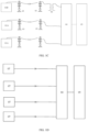
- FIG. 1 A is a schematic diagram of a 10 kV grid power supply system
- FIG. 1 B is a schematic diagram of a 35 kV grid power supply system
- FIG. 1 C is a schematic diagram of a 10 kV/35 kV hybrid grid power supply system
- FIG. 1 D is a schematic diagram illustrating power generation and supply by a generator
- FIG. 2 is a schematic diagram illustrating a module of a power supply system for an electrically driven wellsite facility according to some embodiments of the present disclosure
- FIG. 3 is a schematic diagram illustrating a module of a power supply system with a generator and a power distribution station being disposed in parallel according to some embodiments of the present disclosure
- FIG. 4 is a schematic diagram of a power supply system with a generator and a power distribution station being disposed in parallel according to some embodiments of the present disclosure
- FIG. 5 is a schematic diagram illustrating a module of a power supply system with a generator and a power distribution station being combined to a power grid according to some embodiments of the present disclosure
- FIG. 6 A is a schematic diagram of a power supply system with a generator and a power distribution station being combined to a power grid according to some embodiments of the present disclosure
- FIG. 6 B is a schematic diagram of a power supply system with a generator and a power distribution station being combined to a power grid according to another embodiment of the present disclosure.
- FIG. 7 is a schematic diagram of a power supply system with a generator and a power distribution station being combined to a power grid according to still another embodiment of the present disclosure.
- first,” “second,” and the like as used in embodiments of the present disclosure do not indicate any order, number, or importance, but are used only to distinguish the different components.
- the words “a,” “an,” or “the” and similar words do not indicate quantitative limitations, but rather the presence of at least one.
- words such as “includes” or “contains” are intended to mean that the component or object preceding the word covers the component or object listed after the word and its equivalent, and does not exclude other components or objects.
- Similar words such as “connected” or “connected” are not limited to physical or mechanical connections, but may include electrical connections, whether direct or indirect.
- Flow charts are used in embodiments of the present disclosure to illustrate the steps of the method according to embodiments of the present disclosure. It should be understood that the preceding or following steps do not necessarily follow an exact sequence. Instead, various steps may be addressed in reverse order or simultaneously. Also, other operations may be added to these processes or a step or steps may be removed from these processes.
- the electrical drive operation is high in power, generally about 30 MW, which is far beyond the power consumption of ordinary users. Therefore, a combination of a plurality of power supply modes is required for an electrically driven wellsite facility during electrical drive operation.
- a power grid is used solely to supply power to an electrically driven wellsite facility.
- a generating set such as a turbine generator is used solely to supply power to an electrically driven wellsite facility.
- FIG. 1 A is a schematic diagram of a power supply system with a 10 kV power grid.
- FIG. 1 B is a schematic diagram of a power supply system with a 35 kV grid.
- FIG. 1 C is a schematic diagram of a power supply system with 10 kV/35 kV hybrid power grids.
- FIG. 1 D is a schematic diagram illustrating power generation and supply by a generator.
- the power supply system with the 10 kV power grid includes a plurality of 10 kV power distribution stations (also referred to as 10 kV power grid distribution stations) 01 A, a plurality of towers 03 , 10 kV overhead lines 02 A, and a wellsite power distribution facility 04 .
- 10 kV power grid distribution stations also referred to as 10 kV power grid distribution stations
- the power transmitted from the 10 KV power grid is supplied to an electrically driven wellsite facility 05 .
- the power is transmitted from nearby 10 kV power distribution stations 01 A through the 10 kV overhead lines 02 A to the towers 03 in the vicinity of a well site, subsequently delivered from the towers 03 to the wellsite power distribution facility 04 by using connecting cables and then supplied to the electrically driven wellsite facility 05 .
- FIG. 1 A a simple equipment layout is shown with no need for a step-down transformer.
- the power from one 10 kV power supply line may be insufficient to meet the on-site power demand, and two or more 10 kV power supply lines may often be used to provide power.
- it will easily lead to stepping down of system voltage. As a result, the facility will be prone to shutdown when the voltage of the power supply system is excessively low.
- the power supply system with the 35 kV power grid includes a 35 kV power distribution station (also referred to as 35 kV power grid distribution station) 01 B, a plurality of towers 03 , a 35 kV overhead line 02 B, and a wellsite power distribution facility 04 .
- a 35 kV power distribution station also referred to as 35 kV power grid distribution station
- the power is transmitted from nearby 35 kV power distribution station 01 B through the 35 kV overhead line 02 B to the tower 03 in the vicinity of a well site, subsequently delivered from the tower 03 to the wellsite power distribution facility 04 by using a connecting cable and then supplied to the electrically driven wellsite facility 05 .
- the power supply system with the 35 kV power grid further needs a transformer 06 .
- the transformer 06 is disposed between the tower 03 in the vicinity of the well site and the wellsite power distribution facility 04 to transform the 35 kV voltage into about 10 kV voltage so that the power is smoothly supplied to the electrically driven wellsite facility 05 . Since the 35 kV voltage is relatively high with high single-line power supply capacity, for most of the time, only one 35 kV power supply line can be used to meet the requirement of the well site.
- the power supply system with 10 kV/35 kV hybrid power grid includes a plurality of 10 kV power distribution stations 01 A, a single 35 kV power distribution station 01 B, a plurality of towers 03 , 10 kV overhead lines 02 A, a 35 kV overhead line 02 B, and a wellsite power distribution facility 04 .
- power transmitted from 10 KV and 35 kV power grids is supplied to an electrically driven wellsite facility 05 .
- FIG. 1 C the power supply system with 10 kV/35 kV hybrid power grid includes a plurality of 10 kV power distribution stations 01 A, a single 35 kV power distribution station 01 B, a plurality of towers 03 , 10 kV overhead lines 02 A, a 35 kV overhead line 02 B, and a wellsite power distribution facility 04 .
- 10 KV and 35 kV power grids is supplied to an electrically driven wellsite facility 05 .
- the power is transmitted from nearby 10 kV power distribution stations 01 A and 35 kV power distribution station 01 B to the towers 03 in the vicinity of a well site through the 10 kV overhead lines 02 A and the 35 kV overhead line 02 B, respectively, subsequently delivered from the towers 03 to the wellsite power distribution facility 04 by using connecting cables and then supplied to the electrically driven wellsite facility 05 .
- the working voltage of the electrically driven wellsite facility 05 is generally about 10 kV
- the power grid corresponding to the 35 kV power supply further needs a transformer 06 .
- the transformer 06 is disposed between the tower 03 in the vicinity of the well site and the wellsite power distribution facility 04 to transform the 35 kV voltage into about 10 kV voltage so that the power is smoothly supplied to the electrically driven wellsite facility 05 .
- the power supply scheme with 10 kV/35 kV hybrid power grids involves two lines of power supply and can be adapted to different power grid environments, and when one line of power supply is out of order, the other line of power supply can still work normally.
- this power supply mode with hybrid power grids relates to the design of two power sources, and the technical solution is complex.
- a generator power supply system includes a plurality of turbine generators 07 , 10 kV cables 08 , and a wellsite power distribution facility 04 .
- the turbine generators 07 disposed within a well site generate power for supplying to an electrically driven wellsite facility 05 .
- the power generated by the turbine generators 07 is transmitted to the wellsite power distribution facility 04 through a parallel operation device, and supplied to the electrically driven wellsite facility 05 .
- the power generated by the turbine generators 07 is transmitted to the wellsite power distribution facility without passing through the power grid. Due to a short transmission path, it is unnecessary to add a voltage compensator on site. However, in this case, a gas supply pipeline needs to be led into the well site to supply gas to the generators, and a long power supply pipeline needs to be laid.
- Embodiments of the present disclosure provide a power supply system for an electrically driven wellsite facility.
- the power supply system includes a combined power supply module configured for electrical connection with the electrically driven wellsite facility.
- the combined power supply module includes at least one generator and at least one power distribution station, where the at least one generator and the at least one power distribution station are disposed in parallel or combined to a power grid for supplying power to the electrically driven wellsite facility.
- the power supply system provided in the embodiments of the present disclosure described above which supplies power to an electrically driven wellsite facility using a power grid in combination with on-site generators, can be adapted to different wellsite operation situations and can meet the power requirements of various electrically driven wellsite facilities during operation.
- FIG. 2 is a schematic diagram illustrating a module of a power supply system for an electrically driven wellsite facility according to some embodiments of the present disclosure.
- At least one embodiment of the present disclosure provides a power supply system 200 for an electrically driven wellsite facility 100 .
- the power supply system 200 includes a combined power supply module 210 configured for electrical connection with the electrically driven wellsite facility 100 .
- the combined power supply module 210 includes at least one generator 211 and at least one power distribution station 212 .
- the at least one generator 211 and the at least one power distribution station 212 are disposed in parallel or combined to a power grid for supplying power to the electrically driven wellsite facility 100 .
- the power supply system 200 provided in the above embodiment which supplies power to an electrically driven wellsite facility with a power grid in combination on-site generators, can be adapted to different wellsite operation situations and can meet the power requirements of various electrically driven wellsite facilities during operation.
- the power supply system 200 further includes a wellsite power distribution facility 220 .
- the wellsite power distribution facility 220 is configured to distribute power to and control the electrically driven wellsite facility 100 and may further provide power-off protection for the electrically driven wellsite facility 100 .
- the wellsite power distribution facility 220 is disposed between the combined power supply module 210 and the electrically driven wellsite facility 100 and electrically connected to each of the combined power supply module 210 and the electrically driven wellsite facility 100 .
- FIG. 2 is a block diagram approximately illustrating the electrically driven wellsite facility 100 in the present disclosure, which does not limit the present disclosure.
- the electrically driven wellsite facility 100 in the embodiments of the present disclosure may be one or more specific electrically driven wellsite facilities.
- the electrically driven wellsite facilities 100 include a fracturing facility, a sand blender, a batcher, etc, which are not the focus of description in the present disclosure and will not be described redundantly here.
- the working voltage of the electrically driven wellsite facility 100 is about 10 kV. This is merely illustrative and not limiting of the present disclosure.
- the output voltage of the generator 211 is 10 kV to 15 kV.
- the generator 211 is suitable for the electrically driven wellsite facility 100 , thus effectively supplying power to the electrically driven wellsite facility 100 .
- the output voltage of the generator 211 is 13.8 kV. This is merely illustrative and not limiting of the present disclosure.
- the generator 211 is a turbine generator. This is merely illustrative and not limiting of the present disclosure.
- the generator 211 may further be other types of generators, which will not be described redundantly here.
- FIG. 3 is a schematic diagram illustrating a module of a power supply system with a generator and a power distribution station being disposed in parallel according to some embodiments of the present disclosure.
- each power distribution station 212 ( FIG. 3 merely shows two power distribution stations) is disposed in parallel to each generator 211 ( FIG. 3 merely shows one generator 211 ).
- An output end of the generator 211 is electrically connected to an electrically driven wellsite facility 100
- an output end of the power distribution station 212 is electrically connected to the electrically driven wellsite facility 100 .
- the embodiments of the present disclosure may achieve combined power supply with a generator and an external power grid being disposed in parallel.
- the generator is a turbine generator within a well site.
- the turbine generator and the external power grid can supply power to the electrically driven wellsite facility individually at the same time.
- the power supply system can still work continuously, leading to high reliability of the power supply system.
- the combined power supply module 210 may include one or more power distribution stations 212 , and one or more generators 211 .
- the number of the power distribution stations and the number of generators will not be limited by the embodiments of the present disclosure and can be determined depending on the operation condition of a well site, which will not be described redundantly here.
- the wellsite power distribution facility 220 is disposed between the combined power supply module 210 and the electrically driven wellsite facility 100 , i.e., the wellsite power distribution facility 220 is disposed between the generator 211 and the electrically driven wellsite facility 100 and between the power distribution station 212 and the electrically driven wellsite facility 100 .
- An input end of the wellsite power distribution facility 220 is electrically connected to each of the output end of the generator 211 and the output end of the power distribution station 212 , respectively, and an output end of the wellsite power distribution facility 220 is electrically connected to the electrically driven wellsite facility 100 .
- the embodiments of the present disclosure allow for power distribution and control on electrically driven wellsite facilities by disposing a wellsite power distribution facility in a well site, and achieve electrical drive operation for a plurality of electrically driven wellsite facilities such as a fracturing facility and a sand blender in the well site.
- FIG. 4 is a schematic diagram of a power supply system with a generator and a power distribution station being disposed in parallel according to some embodiments of the present disclosure.
- the combined power supply module 210 further includes a parallel operation device 213 a ( FIG. 4 merely shows one parallel operation device 213 a ).
- the parallel operation device 213 a is disposed between a generator 211 ( FIG. 4 merely shows one generator 211 ) and a wellsite power distribution facility 220 and electrically connected to each of an output end of the generator 211 and the wellsite power distribution facility 220 .
- the parallel operation device 213 a is used to regulate the frequency, voltage and phase of the generator 211 .
- the generator 211 is coupled with the wellsite power distribution facility 220 so that the power generated by the generator 211 is endlessly transmitted and supplied to an electrically driven wellsite facility 100 .
- the parallel operation device 213 a used in the embodiments of the present disclosure may be a parallel operation device in the prior art, which will not be described redundantly here. It needs to be noted that the parallel operation device 213 a refers to a first parallel operation device of the present disclosure.
- the parallel operation device may include a synchronizing device.
- the power supply system 200 further includes an overhead line 230 .
- a head end of the overhead line 230 is electrically connected to an output end of a power distribution station 212
- a tail end of the overhead line 230 is electrically connected to the wellsite power distribution facility 220 .
- the power from an external power grid is transmitted to an electrically driven wellsite facility via the power distribution station 212 and through the overhead line 230 .
- At least one power distribution station 212 of the combined power supply module 210 includes a power distribution station 212 a ( FIG. 4 merely shows one power distribution station 212 a ).
- the power supply system 200 further includes a voltage compensator 240 .
- the voltage compensator 240 is disposed between the tail end of the overhead line 230 and the wellsite power distribution facility 220 .
- the tail end of the overhead line 230 is connected to the wellsite power distribution facility 220 by a connecting cable 250
- the voltage compensator 240 is electrically connected to the connecting cable 250 .
- the power supply system 200 in this embodiment is simple in arrangement and can directly supply power to an electrically driven wellsite facility with no need for a transformer, and the voltage compensator 240 is disposed behind the power distribution station 212 a so that the problem of decreasing of system voltage due to the rise of power during the operation of the facility can be avoided. As a result, the shutdown of the facility can be prevented when the system voltage is excessively low.
- the voltage compensator 240 used in the embodiments of the present disclosure may be a voltage compensator in the prior art, which will not be described redundantly here. It needs to be noted that the power distribution station 212 a refers to a first power distribution station of the present disclosure.
- At least one power distribution station 212 of the combined power supply module 210 includes a power distribution station 212 b ( FIG. 4 merely shows one power distribution station 212 b ).
- the power supply system 200 further includes a step-down transformer 260 .
- the step-down transformer 260 is disposed between the tail end of the overhead line 230 and the wellsite power distribution facility 220 and electrically connected to each of the tail end of the overhead line 230 and the wellsite power distribution facility 220 .
- the step-down transformer 260 is disposed behind the power distribution station 212 b to step down the voltage transmitted from the power distribution station 212 b and transform the voltage into a voltage suitable for the electrically driven wellsite facility 100 , thus smoothly supplying power to the electrically driven wellsite facility 100 .
- the power distribution station 212 b refers to a second power distribution station of the present disclosure.
- the combined power supply module 210 may include one or more power distribution stations 212 a , and one or more power distribution stations 212 b .
- the number of the power distribution stations will not be limited by the embodiments of the present disclosure and can be determined depending on an actual situation, which will not be described redundantly here.
- a power distribution voltage of the power distribution station 212 b is greater than that of the power distribution station 212 a .
- the power distribution station 212 a includes a 10 kV power distribution station
- the power distribution station 212 b includes a 35 kV power distribution station.
- the power distribution voltage of the power distribution station 212 in the embodiments of the present disclosure may range from 10 kV to 220 kV, which will not be described redundantly here.
- the overhead line 230 is adaptable to the power distribution voltage of the power distribution station 212 .
- the overhead line 230 is a suitable 10 kV overhead line.
- the overhead line 230 is a suitable 35 kV overhead line.
- the step-down transformer 260 may be equipped with an automatic voltage regulator so that the problem of stepping down of system voltage due to the rise of power during the operation of a facility can be avoided. As a result, the protection shutdown of the facility can be prevented.
- the voltage regulator used in the embodiments of the present disclosure may be a voltage regulator in the prior art, which will not be described redundantly here.
- the power supply system 200 in the above embodiments of the present disclosure supplies power to the electrically driven wellsite facility 100 using a plurality of lines of power supply.
- the power demand of a well site can also be met.
- the power supply system 200 further includes a plurality of towers 270 ( FIG. 4 merely shows two towers).
- the overhead line 230 is erected between every two towers 270 among a plurality of towers 270 .
- FIG. 5 is a schematic diagram illustrating a module of a power supply system with a generator and a power distribution station being combined to a power grid according to some embodiments of the present disclosure.
- each power distribution station 212 ( FIG. 5 shows three power distribution stations 212 ) and a corresponding generator 211 ( FIG. 5 shows three generators 211 ) are combined to a power grid.
- the input end of each power distribution station 212 is electrically connected to the output end of the corresponding generator 211
- the output end of each power distribution station 212 is electrically connected to an electrically driven wellsite facility 100 .
- the combined power supply module 210 may include one or more power distribution stations 212 .
- the number of the power distribution stations will not be limited by the embodiments of the present disclosure and can be determined depending on the actual demand of a well site.
- generators are combined to an external power grid to achieve combined power supply.
- the power demand in operation in a well site can be met, and power can be transmitted to the power grid to produce extra economic benefits.
- the generators can always work at full load.
- the power supply system can make full use of the generators, and the generators can be maintained and utilized favorably. For example, when an electrically driven wellsite facility operates, the power generated by the generators can be consumed. When the electrically driven wellsite facility stops operating, the power generated by the generators can be allocated to other places of the power grid.
- the generators 211 are disposed in the vicinity of the power distribution stations 212 of the power grid, i.e., the power distribution stations 212 and the generators 211 are not within the well site.
- the electrical connection of the generators 211 with the power distribution stations 212 can be facilitated, and the generators 211 can be disposed in the vicinity of a gas source thereof.
- the preliminary work load can be greatly saved, and resource waste can be avoided. Further, short construction period and good economic benefits can be achieved.
- a wellsite power distribution facility 220 is disposed between the power distribution stations 212 and the electrically driven wellsite facility 100 and electrically connected to each of the output ends of the power distribution stations 212 and the electrically driven wellsite facility 100 .
- the embodiments of the present disclosure allow for power distribution and control on electrically driven wellsite facilities by disposing a wellsite power distribution facility in a well site, and achieve electrical drive operation for a plurality of electrically driven wellsite facilities such as a fracturing facility and a sand blender in the well site.
- FIG. 6 A is a schematic diagram of a power supply system with a generator and a power distribution station being combined to a power grid according to some embodiments of the present disclosure.
- the combined power supply module 210 further includes parallel operation devices 213 b ( FIG. 6 A shows three parallel operation devices 213 b ).
- Each parallel operation device 213 a is disposed between a corresponding generator 211 and a corresponding power distribution station 212 and electrically connected to the output end of the generator 211 and the power distribution station 212 .
- the parallel operation devices 213 b are used to regulate the frequencies, voltages and phases of the generators 211 for keeping consistent with those of the power distribution stations 212 of the power grid.
- the generators 211 can be coupled with the power distribution stations 212 of the power grid so that the power generated can be combined to the power grid.
- the parallel operation device 213 b used in the embodiments of the present disclosure may be a parallel operation device in the prior art, which will not be described redundantly here. It needs to be noted that the parallel operation device 213 b refers to a second parallel operation device of the present disclosure.
- the power supply system 200 further includes overhead lines 230 .
- the head ends of the overhead lines 230 are electrically connected to the output ends of the power distribution stations 212
- the tail ends of the overhead lines 230 are electrically connected to a wellsite power distribution facility 220 .
- the generators 211 are combined to the external power grid.
- the power generated by the generators 211 is delivered to nearby power distribution stations 212 through the parallel operation devices 213 b .
- the power distribution stations 212 then transmit the power to the electrically driven wellsite facility 100 through the overhead lines 230 .
- At least one power distribution station 212 of the combined power supply module 210 includes a power distribution station 212 a (for example, three power distribution stations 212 shown in FIG. 6 A are power distribution stations 212 a ).
- the power supply system 200 further includes voltage compensators 240 ( FIG. 6 A shows three voltage compensators 240 ), and each power distribution station 212 a corresponds to one voltage compensator 240 .
- the voltage compensators 240 are disposed between the tail ends of the overhead lines 230 and the wellsite power distribution facility 220 .
- the tail ends of the overhead lines 230 are connected to the wellsite power distribution facility 220 by connecting cables 250 , and the voltage compensators 240 are electrically connected to the corresponding connecting cables 250 , respectively.
- the power supply system is simple in arrangement and can directly supply power to the electrically driven wellsite facility 100 with no need for a transformer, and the voltage compensators 240 are disposed behind the power distribution stations 212 a so that the problem of stepping down of system voltage due to the rise of power during the operation of the facility can be avoided. As a result, the shutdown of the facility can be prevented when the system voltage is excessively low.
- the power distribution station 212 a includes a 10 kV power distribution station.
- this is merely illustrative and not limiting of the present disclosure.
- the power supply system 200 further includes a plurality of towers 270 ( FIG. 6 A merely shows two towers).
- the overhead line 230 is erected between every two towers 270 among a plurality of towers 270 .
- FIG. 6 B is a schematic diagram of a power supply system with a generator and a power distribution station being combined to a power grid according to another embodiment of the present disclosure.
- the combined power supply module 210 includes at least one parallel operation device 213 b (e.g., FIG. 6 B shows three parallel operation devices 213 b ).
- Each parallel operation device 213 b is disposed between a plurality of corresponding generators 211 and a corresponding power distribution station 212 and electrically connected to the output ends of the plurality of corresponding generators 211 and the power distribution station 212 .
- each parallel operation device 213 b and each power distribution station 212 correspond to two generators 211 , respectively.
- each parallel operation device 213 b may also correspond to more than three generators, which will not be described redundantly here.
- the parallel operation devices 213 b are used to regulate the frequencies, voltages and phases of the generators 211 for keeping consistent with those of the power distribution stations 212 of the power grid.
- a plurality of generators 211 are coupled in parallel for use, and the generators 211 and the corresponding power distribution stations 212 thus can be combined to the power grid. Accordingly, the power generated can be combined to the power grid and then supplied to the electrically driven wellsite facility 100 .
- the generators are combined to an external power grid to achieve combined power supply for an electrically driven wellsite facility.
- the generators can always work at full load.
- the power supply system can make full use of the generators, and the generators can be maintained and utilized favorably.
- FIG. 7 is a schematic diagram of a power supply system with a generator and a power distribution station being combined to a power grid according to still another embodiment of the present disclosure.
- At least one power distribution station of the combined power supply module 210 includes a power distribution station 212 b ( FIG. 7 shows one power distribution station 212 b ).
- the power supply system 200 further includes an overhead line 230 .
- the head end of the overhead line 230 is electrically connected to the output end of the power distribution station 212 b
- the tail end of the overhead line 230 is electrically connected to a wellsite power distribution facility 220 .
- the power supply system 200 further includes a step-down transformer 260 .
- the step-down transformer 260 is disposed between the tail end of the overhead line 230 and the wellsite power distribution facility 220 and electrically connected to each of the tail end of the overhead line 230 and the wellsite power distribution facility 220 .
- the step-down transformer 260 is disposed behind the power distribution station 212 b to step down the voltage transmitted from the power distribution station 212 b and transform the voltage into a voltage suitable for the electrically driven wellsite facility 100 , thus smoothly supplying power to the electrically driven wellsite facility 100 .
- the combined power supply module 210 further includes a parallel operation device 213 b ( FIG. 7 shows one parallel operation device 213 b ).
- the parallel operation device 213 b is disposed between a corresponding generator 211 and a corresponding power distribution station 212 b and electrically connected to each of the output end of the generator 211 and the power distribution station 212 b .
- the parallel operation device 213 b is used to regulate the frequency, voltage and phase of the generator 211 for keeping consistent with those of the power distribution station 212 of the power grid.
- the generators 211 can be coupled with the power distribution station 212 b of the power grid so that the power generated can be combined to the power grid. Accordingly, the power generated by the generator 211 is endlessly transmitted and supplied to the electrically driven wellsite facility 100 .
- the combined power supply module 210 further includes a step-up transformer 280 .
- the step-up transformer 280 is disposed between the power distribution station 212 b and the parallel operation device 213 b and electrically connected to each of the parallel operation device 213 b and the power distribution station 212 b .
- the power generated by the generator 211 is delivered through the parallel operation device 213 b and then stepped up in voltage by the step-up transformer 280 so that the voltage is adapted to the power distribution station 212 b .
- the power distribution station 212 b transmits the power to the step-down transformer 260 through the overhead line 230 , and the step-down transformer 260 steps down the voltage transmitted from the power distribution station 212 b and transforms the voltage into a voltage suitable for the electrically driven wellsite facility 100 , thus smoothly supplying power to the electrically driven wellsite facility 100 .
- the power distribution station 212 b includes a 35 kV power distribution station.
- the power generated by the generator 211 passes through the power distribution station 213 b and then is delivered to the step-up transformer 280 so that its voltage is stepped up to 35 kV.
- the step-up transformer 280 and the step-down transformer 260 used in the embodiments of the present disclosure may be transformers in the prior art, which will not be described redundantly here.
- the generator is combined to an external power grid to achieve combined power supply for an electrically driven wellsite facility.
- the generator can always work at full load.
- the power supply system can make full use of the generator, and the generator can be maintained and utilized favorably.
- FIG. 7 merely illustrates the case in which each of the power distribution station 212 b and the parallel operation device 213 b corresponds to a single generator 211 .
- the embodiments of the present disclosure are not limited thereto, and there may be a case in which each of the power distribution station 212 b and the parallel operation device 213 b corresponds to a plurality of generators 211 (see the above relevant description in the example of FIG. 6 B for details), which will not be described redundantly here.
Landscapes
- Engineering & Computer Science (AREA)
- Power Engineering (AREA)
- Direct Current Feeding And Distribution (AREA)
- Life Sciences & Earth Sciences (AREA)
- Geology (AREA)
- Mining & Mineral Resources (AREA)
- Supply And Distribution Of Alternating Current (AREA)
- Physics & Mathematics (AREA)
- Environmental & Geological Engineering (AREA)
- Fluid Mechanics (AREA)
- General Life Sciences & Earth Sciences (AREA)
- Geochemistry & Mineralogy (AREA)
Abstract
Description
-
- (1) The accompanying drawings related to the embodiments of the present disclosure involve only the structures in connection with the embodiments of the present disclosure, and other structures can be referred to common designs.
- (2) In case of no conflict, features in one embodiment or in different embodiments of the present disclosure can be combined to obtain new embodiments.
Claims (16)
Priority Applications (1)
| Application Number | Priority Date | Filing Date | Title |
|---|---|---|---|
| US18/678,855 US20240313546A1 (en) | 2021-10-12 | 2024-05-30 | Power supply system for electrically driven wellsite facility |
Applications Claiming Priority (2)
| Application Number | Priority Date | Filing Date | Title |
|---|---|---|---|
| CN202122451510.9U CN215870792U (en) | 2021-10-12 | 2021-10-12 | Power supply system for wellsite electric drive equipment |
| CN202122451510.9 | 2021-10-12 |
Related Child Applications (1)
| Application Number | Title | Priority Date | Filing Date |
|---|---|---|---|
| US18/678,855 Continuation-In-Part US20240313546A1 (en) | 2021-10-12 | 2024-05-30 | Power supply system for electrically driven wellsite facility |
Publications (2)
| Publication Number | Publication Date |
|---|---|
| US20230116458A1 US20230116458A1 (en) | 2023-04-13 |
| US12021389B2 true US12021389B2 (en) | 2024-06-25 |
Family
ID=80259639
Family Applications (1)
| Application Number | Title | Priority Date | Filing Date |
|---|---|---|---|
| US17/693,170 Active 2042-06-09 US12021389B2 (en) | 2021-10-12 | 2022-03-11 | Power supply system for electrically driven wellsite facility |
Country Status (3)
| Country | Link |
|---|---|
| US (1) | US12021389B2 (en) |
| CN (1) | CN215870792U (en) |
| WO (1) | WO2023060704A1 (en) |
Families Citing this family (31)
| Publication number | Priority date | Publication date | Assignee | Title |
|---|---|---|---|---|
| US10895202B1 (en) | 2019-09-13 | 2021-01-19 | Bj Energy Solutions, Llc | Direct drive unit removal system and associated methods |
| CA3197583A1 (en) | 2019-09-13 | 2021-03-13 | Bj Energy Solutions, Llc | Fuel, communications, and power connection systems and related methods |
| CA3191280A1 (en) | 2019-09-13 | 2021-03-13 | Bj Energy Solutions, Llc | Methods and systems for supplying fuel to gas turbine engines |
| US12338772B2 (en) | 2019-09-13 | 2025-06-24 | Bj Energy Solutions, Llc | Systems, assemblies, and methods to enhance intake air flow to a gas turbine engine of a hydraulic fracturing unit |
| US11015594B2 (en) | 2019-09-13 | 2021-05-25 | Bj Energy Solutions, Llc | Systems and method for use of single mass flywheel alongside torsional vibration damper assembly for single acting reciprocating pump |
| CA3092863C (en) | 2019-09-13 | 2023-07-18 | Bj Energy Solutions, Llc | Fuel, communications, and power connection systems and related methods |
| US11002189B2 (en) | 2019-09-13 | 2021-05-11 | Bj Energy Solutions, Llc | Mobile gas turbine inlet air conditioning system and associated methods |
| US12065968B2 (en) | 2019-09-13 | 2024-08-20 | BJ Energy Solutions, Inc. | Systems and methods for hydraulic fracturing |
| US10815764B1 (en) | 2019-09-13 | 2020-10-27 | Bj Energy Solutions, Llc | Methods and systems for operating a fleet of pumps |
| US10961914B1 (en) | 2019-09-13 | 2021-03-30 | BJ Energy Solutions, LLC Houston | Turbine engine exhaust duct system and methods for noise dampening and attenuation |
| CA3092865C (en) | 2019-09-13 | 2023-07-04 | Bj Energy Solutions, Llc | Power sources and transmission networks for auxiliary equipment onboard hydraulic fracturing units and associated methods |
| US11708829B2 (en) | 2020-05-12 | 2023-07-25 | Bj Energy Solutions, Llc | Cover for fluid systems and related methods |
| US10968837B1 (en) | 2020-05-14 | 2021-04-06 | Bj Energy Solutions, Llc | Systems and methods utilizing turbine compressor discharge for hydrostatic manifold purge |
| US11428165B2 (en) | 2020-05-15 | 2022-08-30 | Bj Energy Solutions, Llc | Onboard heater of auxiliary systems using exhaust gases and associated methods |
| US11208880B2 (en) | 2020-05-28 | 2021-12-28 | Bj Energy Solutions, Llc | Bi-fuel reciprocating engine to power direct drive turbine fracturing pumps onboard auxiliary systems and related methods |
| US11109508B1 (en) | 2020-06-05 | 2021-08-31 | Bj Energy Solutions, Llc | Enclosure assembly for enhanced cooling of direct drive unit and related methods |
| US11208953B1 (en) | 2020-06-05 | 2021-12-28 | Bj Energy Solutions, Llc | Systems and methods to enhance intake air flow to a gas turbine engine of a hydraulic fracturing unit |
| US10954770B1 (en) | 2020-06-09 | 2021-03-23 | Bj Energy Solutions, Llc | Systems and methods for exchanging fracturing components of a hydraulic fracturing unit |
| US11066915B1 (en) | 2020-06-09 | 2021-07-20 | Bj Energy Solutions, Llc | Methods for detection and mitigation of well screen out |
| US11125066B1 (en) | 2020-06-22 | 2021-09-21 | Bj Energy Solutions, Llc | Systems and methods to operate a dual-shaft gas turbine engine for hydraulic fracturing |
| US11028677B1 (en) | 2020-06-22 | 2021-06-08 | Bj Energy Solutions, Llc | Stage profiles for operations of hydraulic systems and associated methods |
| US11933153B2 (en) | 2020-06-22 | 2024-03-19 | Bj Energy Solutions, Llc | Systems and methods to operate hydraulic fracturing units using automatic flow rate and/or pressure control |
| US11939853B2 (en) | 2020-06-22 | 2024-03-26 | Bj Energy Solutions, Llc | Systems and methods providing a configurable staged rate increase function to operate hydraulic fracturing units |
| US11466680B2 (en) | 2020-06-23 | 2022-10-11 | Bj Energy Solutions, Llc | Systems and methods of utilization of a hydraulic fracturing unit profile to operate hydraulic fracturing units |
| US11473413B2 (en) | 2020-06-23 | 2022-10-18 | Bj Energy Solutions, Llc | Systems and methods to autonomously operate hydraulic fracturing units |
| US11220895B1 (en) | 2020-06-24 | 2022-01-11 | Bj Energy Solutions, Llc | Automated diagnostics of electronic instrumentation in a system for fracturing a well and associated methods |
| US11149533B1 (en) | 2020-06-24 | 2021-10-19 | Bj Energy Solutions, Llc | Systems to monitor, detect, and/or intervene relative to cavitation and pulsation events during a hydraulic fracturing operation |
| US11193361B1 (en) | 2020-07-17 | 2021-12-07 | Bj Energy Solutions, Llc | Methods, systems, and devices to enhance fracturing fluid delivery to subsurface formations during high-pressure fracturing operations |
| US11639654B2 (en) | 2021-05-24 | 2023-05-02 | Bj Energy Solutions, Llc | Hydraulic fracturing pumps to enhance flow of fracturing fluid into wellheads and related methods |
| US12378864B2 (en) | 2021-10-25 | 2025-08-05 | Bj Energy Solutions, Llc | Systems and methods to reduce acoustic resonance or disrupt standing wave formation in a fluid manifold of a high-pressure fracturing system |
| US11955782B1 (en) | 2022-11-01 | 2024-04-09 | Typhon Technology Solutions (U.S.), Llc | System and method for fracturing of underground formations using electric grid power |
Citations (170)
| Publication number | Priority date | Publication date | Assignee | Title |
|---|---|---|---|---|
| US1711979A (en) | 1925-09-21 | 1929-05-07 | Siemens Ag | Electric machine with variable pole numbers |
| US2015745A (en) | 1930-03-29 | 1935-10-01 | Derl Max | Electrical system |
| US3035222A (en) | 1959-07-16 | 1962-05-15 | Robbins & Myers | Means for d.-c. field excitation in alternator sets |
| US3378755A (en) | 1964-04-10 | 1968-04-16 | Gen Motors Corp | Alternator power supply system |
| US3453443A (en) | 1966-07-28 | 1969-07-01 | Gen Electric | Gas turbine mobile powerplant |
| US3794377A (en) | 1972-06-05 | 1974-02-26 | E Wachsmuth | Compressor enclosure |
| US3815965A (en) | 1972-10-10 | 1974-06-11 | Smith & Co Inc Gordon | Air compressor housings |
| US4136432A (en) | 1977-01-13 | 1979-01-30 | Melley Energy Systems, Inc. | Mobile electric power generating systems |
| US4201523A (en) | 1978-01-23 | 1980-05-06 | Olofsson Bjorn O E | Device for cooling and silencing of noise of a compressor or vacuum pump |
| US4336485A (en) | 1979-04-26 | 1982-06-22 | Stroud Lebern W | Dual alternator feedback system |
| US4720645A (en) | 1985-11-22 | 1988-01-19 | Stroud Lebern W | Dual output alternator |
| US4793775A (en) | 1984-10-13 | 1988-12-27 | Aspera S.R.L. | Hermetic motor-compressor unit for refrigeration circuits |
| US4904841A (en) | 1988-08-15 | 1990-02-27 | English Dale L | Welder system having controllable dual winding alternator |
| US4992669A (en) | 1989-02-16 | 1991-02-12 | Parmley Daniel W | Modular energy system |
| US5274322A (en) | 1990-06-07 | 1993-12-28 | Nippondenso Co., Ltd. | Alternating current generator for vehicle |
| US5282722A (en) | 1991-06-12 | 1994-02-01 | Wagner Spray Tech Corporation | Electronic pressure control |
| US5517822A (en) | 1993-06-15 | 1996-05-21 | Applied Energy Systems Of Oklahoma, Inc. | Mobile congeneration apparatus including inventive valve and boiler |
| US5614799A (en) | 1994-07-14 | 1997-03-25 | Mts Systems Corporation | Brushless direct current motor having adjustable motor characteristics |
| US5691590A (en) | 1992-10-23 | 1997-11-25 | Nippondenso Co., Ltd. | Alternator with magnetic noise reduction mechanism |
| US5714821A (en) | 1994-02-16 | 1998-02-03 | Marathon Electric Mfg. Corp. | Alternating current generator with direct connected exciter winding |
| US5751150A (en) | 1995-08-11 | 1998-05-12 | Aerovironment | Bidirectional load and source cycler |
| US5821660A (en) | 1997-03-05 | 1998-10-13 | Mts Systems Corporation | Brushless direct current motor having adjustable motor characteristics |
| US5846056A (en) | 1995-04-07 | 1998-12-08 | Dhindsa; Jasbir S. | Reciprocating pump system and method for operating same |
| US5994802A (en) | 1995-09-27 | 1999-11-30 | Denso Corporation | AC generator for vehicle |
| US6121707A (en) | 1998-01-22 | 2000-09-19 | Reliance Electric Technologies, Llc | Electric motor and electric motor stator and method for making same |
| US6134878A (en) | 1997-09-24 | 2000-10-24 | Sts Corporation | Cooling arrangement for a gas turbine driven power system |
| US6281610B1 (en) | 1999-06-29 | 2001-08-28 | General Electric Company | Slip ring brush assembly and method |
| US6331760B1 (en) | 1998-10-06 | 2001-12-18 | Mclane, Jr. Oscar B. | Capacitive induction motor and method |
| US6388869B1 (en) | 2000-09-19 | 2002-05-14 | Solutions Jupiter Inc. | Mobile generator unit with removable breaker box |
| US6417592B2 (en) | 1999-12-09 | 2002-07-09 | Denso Corporation | Rotary electric machine for vehicle |
| US6450133B1 (en) | 2000-09-19 | 2002-09-17 | Solutions Jupiter Inc. | Partitioned container for high output mobile generator |
| US6455974B1 (en) | 2000-09-28 | 2002-09-24 | General Electric Company | Combined Delta-Wye armature winding for synchronous generators and method |
| US20030030246A1 (en) | 2001-08-08 | 2003-02-13 | Edmund Campion | Air ducts for portable power modules |
| US20030033994A1 (en) | 2001-08-08 | 2003-02-20 | Edmund Campion | Air provision systems for portable power modules |
| US20030057704A1 (en) | 2001-09-26 | 2003-03-27 | Baten Robert Allen | Mobile power generation unit |
| US20030064858A1 (en) | 2001-09-10 | 2003-04-03 | Nissan Motor Co., Ltd. | Vehicle with clutch for transmission of torque output of motor |
| US6552463B2 (en) | 2000-08-10 | 2003-04-22 | Mitsubishi Denki Kabushiki Kaisha | Dynamo-electric machine having winding phase groups of series-connected windings connected in parallel |
| US20030079479A1 (en) | 2001-10-26 | 2003-05-01 | David Kristich | Trailer mounted mobile power system |
| US20040081561A1 (en) | 2001-02-15 | 2004-04-29 | Shigeki Iwanami | Composite type compressor |
| US20040104577A1 (en) | 2002-12-02 | 2004-06-03 | Alger Matthew J. | Power generation system having an external process module |
| US6784583B2 (en) | 2001-02-20 | 2004-08-31 | Denso Corporation | Rotary electric machine |
| US20040174723A1 (en) | 2001-07-02 | 2004-09-09 | Katsutoshi Yamanaka | Power inverter |
| US20050093496A1 (en) | 2003-10-29 | 2005-05-05 | Nissan Motor Co., Ltd. | Vehicle drive force control apparatus |
| US6893487B2 (en) | 2002-12-23 | 2005-05-17 | Caterpillar Inc | Power generation aftertreatment system having a particulate filter dimensioned to be interchangeable with a muffler |
| US20060066105A1 (en) | 2003-05-15 | 2006-03-30 | Sprint Communications Company L.P. | Mobile-power system with solar-powered hydrogen liberator, fuel cell, turbine, and capacitors |
| US20060066108A1 (en) | 2002-11-15 | 2006-03-30 | Sprint Communications Company L.P. | Mobile-power system utilizing propane generator, fuel cell and super capacitors |
| US20060080971A1 (en) | 2004-03-09 | 2006-04-20 | Vulcan Capital Management | Power trailer structural elements for air flow, sound attenuation and fire suppression |
| US7036310B2 (en) | 2003-10-15 | 2006-05-02 | Honda Motor Co., Ltd. | Hydraulic controller for hydraulic actuator |
| US7075206B1 (en) | 2005-02-07 | 2006-07-11 | Visteon Global Technologies, Inc. | Vehicle alternator stator winding having dual slot configuration |
| US7081682B2 (en) | 2001-08-08 | 2006-07-25 | General Electric Company | Portable power modules and related systems |
| US20060208594A1 (en) | 2004-04-28 | 2006-09-21 | Toshiaki Kashihara | Electric rotating machine |
| US7122913B2 (en) | 2004-07-09 | 2006-10-17 | Wittmar Engineering And Construction, Inc. | Modular power generation apparatus and method |
| US20060260331A1 (en) | 2005-05-11 | 2006-11-23 | Frac Source Inc. | Transportable pumping unit and method of fracturing formations |
| US20070108771A1 (en) | 2005-11-11 | 2007-05-17 | Rodney Jones | Power converters |
| US20070121354A1 (en) | 2005-11-11 | 2007-05-31 | Rodney Jones | Power converters |
| US20070216452A1 (en) | 2006-03-17 | 2007-09-20 | Takaie Matsumoto | Power supply for a vehicle |
| US7608934B1 (en) | 2008-08-14 | 2009-10-27 | F3 & I2, Llc | Power packaging with railcars |
| US7619319B1 (en) | 2008-07-15 | 2009-11-17 | F3 & I2, Llc | Network of energy generating modules for transfer of energy outputs |
| US20090308602A1 (en) | 2008-06-11 | 2009-12-17 | Matt Bruins | Combined three-in-one fracturing system |
| CN101636901A (en) | 2006-11-16 | 2010-01-27 | 康明斯发电Ip公司 | Power Generation Systems with Multiple Generators and/or Inverters |
| CN101639040A (en) | 2009-09-04 | 2010-02-03 | 湘电风能有限公司 | Method and device for controlling low-voltage operation of wind generating set |
| US20100060076A1 (en) | 2008-09-05 | 2010-03-11 | Gemin Paul R | Systems and methods for providing an uninterruptible power supply to a ship-service bus of a marine vessel |
| US20100084922A1 (en) | 2008-07-01 | 2010-04-08 | Converteam Technology Ltd. | Three-Level Inverter |
| US20100135840A1 (en) | 2008-11-28 | 2010-06-03 | Hitachi Industrial Equipment Systems Co., Ltd. | Screw compressor |
| CN101728860A (en) | 2010-01-28 | 2010-06-09 | 郑恩花 | Combined power supply |
| CN201570910U (en) | 2009-12-15 | 2010-09-01 | 南阳四维石油设备工程有限公司 | Concentrated power distribution and monitoring system dedicated for oilfield well sites |
| US20110061411A1 (en) | 2008-02-20 | 2011-03-17 | Jong-Kwon Kim | Linear Compressor |
| US20120002454A1 (en) | 2010-06-30 | 2012-01-05 | Kabushiki Kaisha Yaskawa Denki | Three-level inverter, power conditioner, and power generating system |
| US20120065787A1 (en) | 2010-10-01 | 2012-03-15 | General Electric Company | Household energy management system and method for one or more appliances and power generator |
| CN102574475A (en) | 2009-10-23 | 2012-07-11 | 西门子工业公司 | Peak demand reduction in mining haul trucks utilizing an on-board energy storage system |
| CN102602322A (en) | 2012-03-19 | 2012-07-25 | 西安邦普工业自动化有限公司 | Electrically-driven fracturing pump truck |
| US20120248922A1 (en) | 2011-03-30 | 2012-10-04 | Mitsubishi Electric Corporation | Rotary electric machine |
| US20120255734A1 (en) | 2011-04-07 | 2012-10-11 | Todd Coli | Mobile, modular, electrically powered system for use in fracturing underground formations |
| US8294286B2 (en) | 2008-07-15 | 2012-10-23 | F3 & I2, Llc | Network of energy generating modules for transfer of energy outputs |
| US8294285B2 (en) | 2008-08-14 | 2012-10-23 | F3 & I2, Llc | Power packaging with railcars |
| US20120292992A1 (en) * | 2009-12-04 | 2012-11-22 | Williams Kevin R | Dual fuel system and method of supplying power to loads of a drilling rig |
| CN102810909A (en) | 2012-08-01 | 2012-12-05 | 天津大学 | An energy management method that can realize distributed power supply and load matching |
| US20130063070A1 (en) | 2011-09-13 | 2013-03-14 | Delta Electronics (Shanghai) Co., Ltd. | Medium voltage variable frequency driving system |
| US20130182468A1 (en) | 2011-06-24 | 2013-07-18 | Abb Technology Ltd. | Wind power converter |
| US8495869B2 (en) | 2010-11-02 | 2013-07-30 | Girtz Industries Inc. | Power systems with internally integrated aftertreatment and modular features |
| US8519591B2 (en) | 2009-06-19 | 2013-08-27 | Mitsubishi Electric Corporation | Dynamoelectric machine that increases an output from a rectifier at low speed rotation |
| US20130229836A1 (en) | 2012-03-02 | 2013-09-05 | Delta Electronics (Shanghai) Co., Ltd. | Multiple inverter and active power filter system |
| US20130234522A1 (en) | 2012-03-09 | 2013-09-12 | Delta Electronics, Inc. | Power circuit, converter structure and wind power generation system thereof |
| CN103310963A (en) | 2013-03-26 | 2013-09-18 | 国家电网公司 | Three-winding transformer design method suitable for 35kV distribution construction |
| US20130255153A1 (en) | 2012-03-30 | 2013-10-03 | Hitachi, Ltd. | Method of Gas Purification, Coal Gasification Plant, and Shift Catalyst |
| US8587136B2 (en) | 2010-12-20 | 2013-11-19 | Solar Turbines Inc. | Mobile power system |
| US20140096974A1 (en) | 2012-10-05 | 2014-04-10 | Evolution Well Services | Mobile, Modular, Electrically Powered System For Use in Fracturing Underground Formations Using Liquid Petroleum Gas |
| CN103770852A (en) | 2014-02-26 | 2014-05-07 | 龙岩市海德馨汽车有限公司 | High power and high voltage power supply semitrailer |
| US8731793B2 (en) | 2010-12-29 | 2014-05-20 | Caterpillar Inc. | Clutch temperature estimation for a mobile machine |
| US20140138079A1 (en) | 2012-11-16 | 2014-05-22 | Us Well Services Llc | System for Pumping Hydraulic Fracturing Fluid Using Electric Pumps |
| US20140174717A1 (en) | 2012-11-16 | 2014-06-26 | Us Well Services Llc | System for pumping hydraulic fracturing fluid using electric pumps |
| US20140210213A1 (en) | 2013-01-31 | 2014-07-31 | APR Energy, LLC | Scalable portable modular power plant |
| US20140219824A1 (en) | 2013-02-06 | 2014-08-07 | Baker Hughes Incorporated | Pump system and method thereof |
| US20140312823A1 (en) | 2011-12-20 | 2014-10-23 | Exxonmobil Upstream Research Company | Harmonics Suppression in a Power Delivery Device |
| US20150027712A1 (en) | 2013-07-23 | 2015-01-29 | Baker Hughes Incorporated | Apparatus and methods for delivering a high volume of fluid into an underground well bore from a mobile pumping unit |
| CN104578389A (en) | 2015-01-08 | 2015-04-29 | 华为技术有限公司 | Electric control method, device and system |
| CN204386465U (en) | 2014-12-31 | 2015-06-10 | 西安宝美电气工业有限公司 | A kind of oil field pull-type electric workover rig |
| US20150252661A1 (en) | 2014-01-06 | 2015-09-10 | Lime Instruments Llc | Hydraulic fracturing system |
| US20160041066A1 (en) | 2015-10-23 | 2016-02-11 | Caterpillar Inc. | Method for monitoring temperature of clutch assembly |
| US20160075387A1 (en) | 2014-09-17 | 2016-03-17 | General Electric Company | Systems and methods for a turbine trailer mechanical docking and alignment system |
| US20160105022A1 (en) | 2012-11-16 | 2016-04-14 | Us Well Services Llc | System and method for parallel power and blackout protection for electric powered hydraulic fracturing |
| CA2908276A1 (en) | 2014-10-14 | 2016-04-14 | Us Well Services Llc | Parallel power and blackout protection for electric hydraulic fracturing |
| US20160177678A1 (en) | 2014-12-19 | 2016-06-23 | Evolution Well Services, Llc | Mobile electric power generation for hydraulic fracturing of subsurface geological formations |
| CN105763337A (en) | 2016-03-29 | 2016-07-13 | 杭州华三通信技术有限公司 | Power supply method and device |
| US20160369609A1 (en) | 2014-12-19 | 2016-12-22 | Evolution Well Services, Llc | Mobile fracturing pump transport for hydraulic fracturing of subsurface geological formations |
| US9641112B2 (en) | 2014-12-10 | 2017-05-02 | Clark Equipment Company | Protection method for a generator |
| CN106711990A (en) | 2015-07-29 | 2017-05-24 | 腾讯科技(深圳)有限公司 | Vehicle concentrated power supply device and system |
| US20170154387A1 (en) | 2015-11-04 | 2017-06-01 | Standard Microgrid, Inc. | Electricity Distribution Arrangement, System and Method |
| US20170222409A1 (en) | 2012-11-16 | 2017-08-03 | Us Well Services Llc | Switchgear load sharing for oil field equipment |
| CN107231000A (en) | 2017-07-17 | 2017-10-03 | 国电科学技术研究院 | Large-scale coal generating system and grid-connected power generation system integrated complementary method and system |
| US20170285062A1 (en) | 2016-03-29 | 2017-10-05 | Hyundai Motor Company | Electric oil pump control method for operating transmission of hybrid vehicle |
| CN107240915A (en) | 2016-03-29 | 2017-10-10 | 西门子工厂自动化工程有限公司 | Shore electric power system |
| US20170292789A1 (en) | 2016-04-10 | 2017-10-12 | Global Heat Transfer Ulc | Heat exchanger unit |
| US20170302135A1 (en) | 2016-04-19 | 2017-10-19 | Lime Instruments, Llc | Power system for well service pumps |
| US20170305284A1 (en) | 2016-04-25 | 2017-10-26 | Lsis Co., Ltd. | Charge system for electric vehicle and method for charging electric vehicle |
| US20180059754A1 (en) | 2013-10-28 | 2018-03-01 | Virtual Power Systems, Inc. | Multi-level data center using consolidated power control |
| US20180080377A1 (en) | 2016-09-21 | 2018-03-22 | General Electric Company | Systems and methods for a mobile power plant with improved mobility and reduced trailer count |
| US20180080376A1 (en) | 2016-09-21 | 2018-03-22 | General Electric Company | Systems and methods for a mobile power plant with improved mobility and reduced trailer count |
| US20180156210A1 (en) | 2016-12-02 | 2018-06-07 | U.S. Well Services, LLC | Constant voltage power distribution system for use with an electric hydraulic fracturing system |
| CN207652040U (en) | 2017-12-15 | 2018-07-24 | 华能国际电力股份有限公司 | Incremental power distribution network system |
| US20180287386A1 (en) * | 2015-03-19 | 2018-10-04 | General Electric Technology Gmbh | Power transmission network |
| US20180328157A1 (en) | 2017-05-11 | 2018-11-15 | Mgb Oilfield Solutions, L.L.C. | Equipment, system and method for delivery of high pressure fluid |
| CN108900136A (en) | 2018-07-31 | 2018-11-27 | 中车永济电机有限公司 | A kind of multiphase Frac unit electric driving control system |
| US20190100989A1 (en) | 2017-10-02 | 2019-04-04 | S.P.M. Flow Control, Inc. | System and Method for Universal Fracturing Site Equipment Monitoring |
| CN109572449A (en) | 2018-12-29 | 2019-04-05 | 三重能有限公司 | Electric drive system and quarry tipper |
| US20190128265A1 (en) | 2017-11-02 | 2019-05-02 | Kabushiki Kaisha Kobe Seiko Sho (Kobe Steel, Ltd.) | Gas supplying apparatus |
| US20190157982A1 (en) | 2017-11-20 | 2019-05-23 | Ge Energy Power Conversion Technology Limited | Device and method for premagnetization of a power transformer in a converter system |
| US20190169971A1 (en) | 2017-12-05 | 2019-06-06 | U.S. Well Services, Inc. | High horsepower pumping configuration for an electric hydraulic fracturing system |
| US20190195292A1 (en) | 2017-12-22 | 2019-06-27 | Caterpillar Inc. | Clutch Local Peak Temperature Real Time Predictor and Applications |
| US20190229643A1 (en) | 2018-01-22 | 2019-07-25 | Hamilton Sundstrand Corporation | Alternate grounding of inverter midpoint for three level switching control |
| CN110107490A (en) | 2019-05-30 | 2019-08-09 | 宝鸡石油机械有限责任公司 | Integral type frequency conversion pressure break pumps apparatus control system and control method |
| CN110118127A (en) | 2019-06-13 | 2019-08-13 | 烟台杰瑞石油装备技术有限公司 | A kind of electricity drives the power supply semitrailer of fracturing unit |
| US10411635B2 (en) | 2015-11-06 | 2019-09-10 | Denso Corporation | Rotating electric machine |
| US20190319459A1 (en) | 2018-04-12 | 2019-10-17 | Katerra, Inc. | Method and Apparatus for Dynamic Electrical Load Sensing and Line to Load Switching |
| US20190331080A1 (en) | 2016-06-07 | 2019-10-31 | Thales | Brushless starter generator |
| US20200040878A1 (en) | 2018-08-06 | 2020-02-06 | Typhon Technology Solutions, Llc | Engagement and disengagement with external gear box style pumps |
| US20200040705A1 (en) | 2018-08-01 | 2020-02-06 | Typhon Technology Solutions, Llc | Switch gear transport that distributes electric power for fracturing operations |
| US20200049136A1 (en) | 2016-11-29 | 2020-02-13 | Halliburton Energy Services, Inc. | Dual turbine direct drive pump |
| CN110821464A (en) | 2019-12-03 | 2020-02-21 | 烟台杰瑞石油装备技术有限公司 | A well site layout system for fracturing |
| CN210105993U (en) | 2019-06-13 | 2020-02-21 | 烟台杰瑞石油装备技术有限公司 | Power supply semi-trailer of electrically-driven fracturing equipment |
| CN210183018U (en) | 2019-01-09 | 2020-03-24 | 阿里巴巴集团控股有限公司 | Grid-connected power supply system and grid-connected device of data center |
| US20200109617A1 (en) | 2018-10-09 | 2020-04-09 | U.S. Well Services, LLC | Modular switchgear system and power distribution for electric oilfield equipment |
| CN111181159A (en) | 2020-01-24 | 2020-05-19 | 中国铁塔股份有限公司云南省分公司 | A mobile communication base station load management control device and management control method |
| CN210780534U (en) | 2019-11-28 | 2020-06-16 | 青岛中加特电气股份有限公司 | Direct current bus charging circuit of high-voltage frequency converter |
| US20200270948A1 (en) * | 2017-10-27 | 2020-08-27 | Schlumberger Technology Corporation | Supplemental power unit for drilling rig |
| CN111628519A (en) | 2019-02-28 | 2020-09-04 | 深圳中瀚云科技股份有限公司 | Power supply control method of power supply system, power supply system and storage medium |
| CN111769551A (en) | 2020-06-30 | 2020-10-13 | 中国舰船研究设计中心 | A ship terminal power distribution system |
| US20200325760A1 (en) | 2019-04-12 | 2020-10-15 | The Modern Group, Ltd. | Hydraulic fracturing pump system |
| US10865624B1 (en) | 2019-09-24 | 2020-12-15 | Yantai Jereh Petroleum Equipment & Technologies Co., Ltd. | Wellsite system for electric drive fracturing |
| US10914155B2 (en) | 2018-10-09 | 2021-02-09 | U.S. Well Services, LLC | Electric powered hydraulic fracturing pump system with single electric powered multi-plunger pump fracturing trailers, filtration units, and slide out platform |
| US20210040830A1 (en) | 2018-01-23 | 2021-02-11 | Schlumberger Technology Corporation | Automated Control of Hydraulic Fracturing Pumps |
| US20210040836A1 (en) | 2019-08-07 | 2021-02-11 | CS&P Technologies LP | Lubrication system for a plunger/packing set of a fluid end |
| CN212671744U (en) | 2020-04-26 | 2021-03-09 | 四川宏华石油设备有限公司 | Electric fracturing operation system |
| US20210095648A1 (en) | 2019-10-01 | 2021-04-01 | St9 Gas And Oil, Llc | Electric drive pump for well stimulation |
| US20210102530A1 (en) | 2018-05-01 | 2021-04-08 | Cameron International Corporation | Fluid pumping using electric linear motor |
| US20210102451A1 (en) | 2019-10-03 | 2021-04-08 | U.S. Well Services, LLC | Electric powered hydraulic fracturing pump system with single electric powered multi-plunger fracturing pump |
| US20210107616A1 (en) | 2017-04-18 | 2021-04-15 | Maersk Drilling A/S | Thruster electric power systems and associated methods |
| CN213027453U (en) | 2020-08-31 | 2021-04-20 | 国网青海省电力公司果洛供电公司 | A 10kv line voltage compensation device |
| CN112983382A (en) | 2020-12-04 | 2021-06-18 | 烟台杰瑞石油装备技术有限公司 | Fracturing equipment and fracturing system |
| CN112993965A (en) | 2021-04-25 | 2021-06-18 | 东营市汉德自动化集成有限公司 | Petroleum fracturing direct current transmission power system |
| CN113006757A (en) | 2021-02-25 | 2021-06-22 | 三一石油智能装备有限公司 | Method and device for controlling auxiliary motor equipment in electrically-driven fracturing sled system and fracturing sled |
| US20210199161A1 (en) | 2016-08-05 | 2021-07-01 | Nidec Tosok Corporation | Clutch control device |
| US11109508B1 (en) | 2020-06-05 | 2021-08-31 | Bj Energy Solutions, Llc | Enclosure assembly for enhanced cooling of direct drive unit and related methods |
| US11125066B1 (en) | 2020-06-22 | 2021-09-21 | Bj Energy Solutions, Llc | Systems and methods to operate a dual-shaft gas turbine engine for hydraulic fracturing |
| US20210301630A1 (en) * | 2020-03-31 | 2021-09-30 | Schlumberger Technology Corporation | Power Management at a Wellsite |
| US20210310341A1 (en) | 2018-05-01 | 2021-10-07 | David Sherman | Powertrain for wellsite operations and method |
| US11220895B1 (en) | 2020-06-24 | 2022-01-11 | Bj Energy Solutions, Llc | Automated diagnostics of electronic instrumentation in a system for fracturing a well and associated methods |
| US20220112892A1 (en) | 2019-10-30 | 2022-04-14 | Yantai Jereh Petroleum Equipment & Technologies Co., Ltd. | Variable-speed integrated machine and wellsite apparatus |
| US11378008B2 (en) | 2020-06-05 | 2022-07-05 | Bj Energy Solutions, Llc | Systems and methods to enhance intake air flow to a gas turbine engine of a hydraulic fracturing unit |
| US20220213777A1 (en) | 2019-09-24 | 2022-07-07 | Yantai Jereh Petroleum Equipment & Technologies Co., Ltd. | Electrically-driven fracturing well site system |
-
2021
- 2021-10-12 CN CN202122451510.9U patent/CN215870792U/en active Active
- 2021-11-22 WO PCT/CN2021/132090 patent/WO2023060704A1/en not_active Ceased
-
2022
- 2022-03-11 US US17/693,170 patent/US12021389B2/en active Active
Patent Citations (226)
| Publication number | Priority date | Publication date | Assignee | Title |
|---|---|---|---|---|
| US1711979A (en) | 1925-09-21 | 1929-05-07 | Siemens Ag | Electric machine with variable pole numbers |
| US2015745A (en) | 1930-03-29 | 1935-10-01 | Derl Max | Electrical system |
| US3035222A (en) | 1959-07-16 | 1962-05-15 | Robbins & Myers | Means for d.-c. field excitation in alternator sets |
| US3378755A (en) | 1964-04-10 | 1968-04-16 | Gen Motors Corp | Alternator power supply system |
| US3453443A (en) | 1966-07-28 | 1969-07-01 | Gen Electric | Gas turbine mobile powerplant |
| US3794377A (en) | 1972-06-05 | 1974-02-26 | E Wachsmuth | Compressor enclosure |
| US3815965A (en) | 1972-10-10 | 1974-06-11 | Smith & Co Inc Gordon | Air compressor housings |
| US4136432A (en) | 1977-01-13 | 1979-01-30 | Melley Energy Systems, Inc. | Mobile electric power generating systems |
| US4201523A (en) | 1978-01-23 | 1980-05-06 | Olofsson Bjorn O E | Device for cooling and silencing of noise of a compressor or vacuum pump |
| US4336485A (en) | 1979-04-26 | 1982-06-22 | Stroud Lebern W | Dual alternator feedback system |
| US4793775A (en) | 1984-10-13 | 1988-12-27 | Aspera S.R.L. | Hermetic motor-compressor unit for refrigeration circuits |
| US4720645A (en) | 1985-11-22 | 1988-01-19 | Stroud Lebern W | Dual output alternator |
| US4904841A (en) | 1988-08-15 | 1990-02-27 | English Dale L | Welder system having controllable dual winding alternator |
| US4992669A (en) | 1989-02-16 | 1991-02-12 | Parmley Daniel W | Modular energy system |
| US5274322A (en) | 1990-06-07 | 1993-12-28 | Nippondenso Co., Ltd. | Alternating current generator for vehicle |
| US5282722A (en) | 1991-06-12 | 1994-02-01 | Wagner Spray Tech Corporation | Electronic pressure control |
| US5691590A (en) | 1992-10-23 | 1997-11-25 | Nippondenso Co., Ltd. | Alternator with magnetic noise reduction mechanism |
| US5517822A (en) | 1993-06-15 | 1996-05-21 | Applied Energy Systems Of Oklahoma, Inc. | Mobile congeneration apparatus including inventive valve and boiler |
| US5714821A (en) | 1994-02-16 | 1998-02-03 | Marathon Electric Mfg. Corp. | Alternating current generator with direct connected exciter winding |
| US5614799A (en) | 1994-07-14 | 1997-03-25 | Mts Systems Corporation | Brushless direct current motor having adjustable motor characteristics |
| US5846056A (en) | 1995-04-07 | 1998-12-08 | Dhindsa; Jasbir S. | Reciprocating pump system and method for operating same |
| US5751150A (en) | 1995-08-11 | 1998-05-12 | Aerovironment | Bidirectional load and source cycler |
| US5994802A (en) | 1995-09-27 | 1999-11-30 | Denso Corporation | AC generator for vehicle |
| US5821660A (en) | 1997-03-05 | 1998-10-13 | Mts Systems Corporation | Brushless direct current motor having adjustable motor characteristics |
| US6134878A (en) | 1997-09-24 | 2000-10-24 | Sts Corporation | Cooling arrangement for a gas turbine driven power system |
| US6121707A (en) | 1998-01-22 | 2000-09-19 | Reliance Electric Technologies, Llc | Electric motor and electric motor stator and method for making same |
| US6331760B1 (en) | 1998-10-06 | 2001-12-18 | Mclane, Jr. Oscar B. | Capacitive induction motor and method |
| US6281610B1 (en) | 1999-06-29 | 2001-08-28 | General Electric Company | Slip ring brush assembly and method |
| US6417592B2 (en) | 1999-12-09 | 2002-07-09 | Denso Corporation | Rotary electric machine for vehicle |
| US6552463B2 (en) | 2000-08-10 | 2003-04-22 | Mitsubishi Denki Kabushiki Kaisha | Dynamo-electric machine having winding phase groups of series-connected windings connected in parallel |
| US6388869B1 (en) | 2000-09-19 | 2002-05-14 | Solutions Jupiter Inc. | Mobile generator unit with removable breaker box |
| US6450133B1 (en) | 2000-09-19 | 2002-09-17 | Solutions Jupiter Inc. | Partitioned container for high output mobile generator |
| US6455974B1 (en) | 2000-09-28 | 2002-09-24 | General Electric Company | Combined Delta-Wye armature winding for synchronous generators and method |
| US6704993B2 (en) | 2000-09-28 | 2004-03-16 | General Electric Company | Combined delta-wye armature winding for synchronous generators and method |
| US20040081561A1 (en) | 2001-02-15 | 2004-04-29 | Shigeki Iwanami | Composite type compressor |
| US6784583B2 (en) | 2001-02-20 | 2004-08-31 | Denso Corporation | Rotary electric machine |
| US7016207B2 (en) | 2001-07-02 | 2006-03-21 | Kabushiki Kaisha Yaskawa Denki | Power inverter |
| US20040174723A1 (en) | 2001-07-02 | 2004-09-09 | Katsutoshi Yamanaka | Power inverter |
| US20030030246A1 (en) | 2001-08-08 | 2003-02-13 | Edmund Campion | Air ducts for portable power modules |
| US6895903B2 (en) | 2001-08-08 | 2005-05-24 | General Electric Company | Air provision systems for portable power modules |
| US20030033994A1 (en) | 2001-08-08 | 2003-02-20 | Edmund Campion | Air provision systems for portable power modules |
| US7081682B2 (en) | 2001-08-08 | 2006-07-25 | General Electric Company | Portable power modules and related systems |
| US7007966B2 (en) | 2001-08-08 | 2006-03-07 | General Electric Company | Air ducts for portable power modules |
| US20030064858A1 (en) | 2001-09-10 | 2003-04-03 | Nissan Motor Co., Ltd. | Vehicle with clutch for transmission of torque output of motor |
| US6765304B2 (en) | 2001-09-26 | 2004-07-20 | General Electric Co. | Mobile power generation unit |
| US20030057704A1 (en) | 2001-09-26 | 2003-03-27 | Baten Robert Allen | Mobile power generation unit |
| US6786051B2 (en) | 2001-10-26 | 2004-09-07 | Vulcan Advanced Mobile Power Systems, L.L.C. | Trailer mounted mobile power system |
| US20030079479A1 (en) | 2001-10-26 | 2003-05-01 | David Kristich | Trailer mounted mobile power system |
| US7245032B2 (en) | 2002-11-15 | 2007-07-17 | Sprint Communications Company L.P. | Mobile-power system utilizing propane generator, fuel cell and super capacitors |
| US7615877B2 (en) | 2002-11-15 | 2009-11-10 | Sprint Communications Company L.P. | Power generation system for mobile power supply |
| US20060066108A1 (en) | 2002-11-15 | 2006-03-30 | Sprint Communications Company L.P. | Mobile-power system utilizing propane generator, fuel cell and super capacitors |
| US7635926B2 (en) | 2002-11-15 | 2009-12-22 | Sprint Communications Company L.P. | Redundant mobile power supply system |
| US20040104577A1 (en) | 2002-12-02 | 2004-06-03 | Alger Matthew J. | Power generation system having an external process module |
| US7221061B2 (en) | 2002-12-02 | 2007-05-22 | Caterpillar Inc | Power generation system having an external process module |
| US6893487B2 (en) | 2002-12-23 | 2005-05-17 | Caterpillar Inc | Power generation aftertreatment system having a particulate filter dimensioned to be interchangeable with a muffler |
| US7112891B2 (en) | 2003-05-15 | 2006-09-26 | Sprint Communications Company L.P. | Mobile-power system with solar-powered hydrogen liberator, fuel cell, turbine, and capacitors |
| US20060066105A1 (en) | 2003-05-15 | 2006-03-30 | Sprint Communications Company L.P. | Mobile-power system with solar-powered hydrogen liberator, fuel cell, turbine, and capacitors |
| US7036310B2 (en) | 2003-10-15 | 2006-05-02 | Honda Motor Co., Ltd. | Hydraulic controller for hydraulic actuator |
| US20050093496A1 (en) | 2003-10-29 | 2005-05-05 | Nissan Motor Co., Ltd. | Vehicle drive force control apparatus |
| US20060080971A1 (en) | 2004-03-09 | 2006-04-20 | Vulcan Capital Management | Power trailer structural elements for air flow, sound attenuation and fire suppression |
| US20060208594A1 (en) | 2004-04-28 | 2006-09-21 | Toshiaki Kashihara | Electric rotating machine |
| US7291954B2 (en) | 2004-04-28 | 2007-11-06 | Mitsubishi Denki Kabushiki Kaisha | Dynamoelectric machine |
| US7122913B2 (en) | 2004-07-09 | 2006-10-17 | Wittmar Engineering And Construction, Inc. | Modular power generation apparatus and method |
| US7075206B1 (en) | 2005-02-07 | 2006-07-11 | Visteon Global Technologies, Inc. | Vehicle alternator stator winding having dual slot configuration |
| US20060260331A1 (en) | 2005-05-11 | 2006-11-23 | Frac Source Inc. | Transportable pumping unit and method of fracturing formations |
| US20070108771A1 (en) | 2005-11-11 | 2007-05-17 | Rodney Jones | Power converters |
| US7372174B2 (en) | 2005-11-11 | 2008-05-13 | Converteam Ltd | Power converters |
| US7511385B2 (en) | 2005-11-11 | 2009-03-31 | Converteam Ltd | Power converters |
| US20090146500A1 (en) | 2005-11-11 | 2009-06-11 | Rodney Jones | Power converters |
| US20090147549A1 (en) | 2005-11-11 | 2009-06-11 | Rodney Jones | Power converters |
| US20090146426A1 (en) | 2005-11-11 | 2009-06-11 | Rodney Jones | Power converters |
| US7755209B2 (en) | 2005-11-11 | 2010-07-13 | Converteam Uk Ltd | Power converters |
| US20070121354A1 (en) | 2005-11-11 | 2007-05-31 | Rodney Jones | Power converters |
| US7692321B2 (en) | 2005-11-11 | 2010-04-06 | Converteam Ltd | Power converters |
| US7656052B2 (en) | 2005-11-11 | 2010-02-02 | Converteam Ltd. | Power converters |
| US7667342B2 (en) | 2006-03-17 | 2010-02-23 | Yamaha Hatsudoki Kabushiki Kaisha | Power supply for a vehicle |
| US20070216452A1 (en) | 2006-03-17 | 2007-09-20 | Takaie Matsumoto | Power supply for a vehicle |
| CN101636901A (en) | 2006-11-16 | 2010-01-27 | 康明斯发电Ip公司 | Power Generation Systems with Multiple Generators and/or Inverters |
| US20110061411A1 (en) | 2008-02-20 | 2011-03-17 | Jong-Kwon Kim | Linear Compressor |
| US20090308602A1 (en) | 2008-06-11 | 2009-12-17 | Matt Bruins | Combined three-in-one fracturing system |
| US7921914B2 (en) | 2008-06-11 | 2011-04-12 | Hitman Holdings Ltd. | Combined three-in-one fracturing system |
| US20100084922A1 (en) | 2008-07-01 | 2010-04-08 | Converteam Technology Ltd. | Three-Level Inverter |
| US8294286B2 (en) | 2008-07-15 | 2012-10-23 | F3 & I2, Llc | Network of energy generating modules for transfer of energy outputs |
| US7619319B1 (en) | 2008-07-15 | 2009-11-17 | F3 & I2, Llc | Network of energy generating modules for transfer of energy outputs |
| US8294285B2 (en) | 2008-08-14 | 2012-10-23 | F3 & I2, Llc | Power packaging with railcars |
| US7608934B1 (en) | 2008-08-14 | 2009-10-27 | F3 & I2, Llc | Power packaging with railcars |
| US20100060076A1 (en) | 2008-09-05 | 2010-03-11 | Gemin Paul R | Systems and methods for providing an uninterruptible power supply to a ship-service bus of a marine vessel |
| US8362638B2 (en) | 2008-09-05 | 2013-01-29 | General Electric Company | Systems and methods for providing an uninterruptible power supply to a ship-service bus of a marine vessel |
| US20120175947A1 (en) | 2008-09-05 | 2012-07-12 | General Electric Company | Systems and methods for providing an uninterruptible power supply to a ship-service bus of a marine vessel |
| US8159082B2 (en) | 2008-09-05 | 2012-04-17 | General Electric Company | Systems and methods for providing an uninterruptible power supply to a ship-service bus of a marine vessel |
| US20100135840A1 (en) | 2008-11-28 | 2010-06-03 | Hitachi Industrial Equipment Systems Co., Ltd. | Screw compressor |
| US8519591B2 (en) | 2009-06-19 | 2013-08-27 | Mitsubishi Electric Corporation | Dynamoelectric machine that increases an output from a rectifier at low speed rotation |
| CN101639040A (en) | 2009-09-04 | 2010-02-03 | 湘电风能有限公司 | Method and device for controlling low-voltage operation of wind generating set |
| CN102574475A (en) | 2009-10-23 | 2012-07-11 | 西门子工业公司 | Peak demand reduction in mining haul trucks utilizing an on-board energy storage system |
| US20120292992A1 (en) * | 2009-12-04 | 2012-11-22 | Williams Kevin R | Dual fuel system and method of supplying power to loads of a drilling rig |
| CN201570910U (en) | 2009-12-15 | 2010-09-01 | 南阳四维石油设备工程有限公司 | Concentrated power distribution and monitoring system dedicated for oilfield well sites |
| CN101728860A (en) | 2010-01-28 | 2010-06-09 | 郑恩花 | Combined power supply |
| US20120002454A1 (en) | 2010-06-30 | 2012-01-05 | Kabushiki Kaisha Yaskawa Denki | Three-level inverter, power conditioner, and power generating system |
| US8773876B2 (en) | 2010-06-30 | 2014-07-08 | Kabushiki Kaisha Yaskawa Denki | Three-level inverter, power conditioner, and power generating system |
| US20120065787A1 (en) | 2010-10-01 | 2012-03-15 | General Electric Company | Household energy management system and method for one or more appliances and power generator |
| US8495869B2 (en) | 2010-11-02 | 2013-07-30 | Girtz Industries Inc. | Power systems with internally integrated aftertreatment and modular features |
| US8587136B2 (en) | 2010-12-20 | 2013-11-19 | Solar Turbines Inc. | Mobile power system |
| US8731793B2 (en) | 2010-12-29 | 2014-05-20 | Caterpillar Inc. | Clutch temperature estimation for a mobile machine |
| US20120248922A1 (en) | 2011-03-30 | 2012-10-04 | Mitsubishi Electric Corporation | Rotary electric machine |
| US8796899B2 (en) | 2011-03-30 | 2014-08-05 | Mitsubishi Electric Corporation | Rotary electric machine |
| US11391136B2 (en) | 2011-04-07 | 2022-07-19 | Typhon Technology Solutions (U.S.), Llc | Dual pump VFD controlled motor electric fracturing system |
| US9103193B2 (en) | 2011-04-07 | 2015-08-11 | Evolution Well Services, Llc | Mobile, modular, electrically powered system for use in fracturing underground formations |
| US20120255734A1 (en) | 2011-04-07 | 2012-10-11 | Todd Coli | Mobile, modular, electrically powered system for use in fracturing underground formations |
| US20150068754A1 (en) | 2011-04-07 | 2015-03-12 | Evolution Well Services, Llc | Mobile, modular, electrically powered system for use in fracturing underground formations |
| US20130182468A1 (en) | 2011-06-24 | 2013-07-18 | Abb Technology Ltd. | Wind power converter |
| US9166495B2 (en) | 2011-06-24 | 2015-10-20 | Abb Technology Ltd. | Wind power converter |
| US8811048B2 (en) | 2011-09-13 | 2014-08-19 | Delta Electronics (Shanghai) Co., Ltd. | Medium voltage variable frequency driving system |
| US20130063070A1 (en) | 2011-09-13 | 2013-03-14 | Delta Electronics (Shanghai) Co., Ltd. | Medium voltage variable frequency driving system |
| US9209704B2 (en) | 2011-12-20 | 2015-12-08 | Exxonmobil Upstream Research Company | Harmonics suppression in a power delivery device |
| US20140312823A1 (en) | 2011-12-20 | 2014-10-23 | Exxonmobil Upstream Research Company | Harmonics Suppression in a Power Delivery Device |
| US20130229836A1 (en) | 2012-03-02 | 2013-09-05 | Delta Electronics (Shanghai) Co., Ltd. | Multiple inverter and active power filter system |
| US8670260B2 (en) | 2012-03-02 | 2014-03-11 | Delta Electronics (Shanghai) Co., Ltd. | Multiple inverter and active power filter system |
| US9577545B2 (en) | 2012-03-09 | 2017-02-21 | Delta Electronics, Inc. | Power circuit, converter structure and wind power generation system thereof |
| US20130234522A1 (en) | 2012-03-09 | 2013-09-12 | Delta Electronics, Inc. | Power circuit, converter structure and wind power generation system thereof |
| CN102602322A (en) | 2012-03-19 | 2012-07-25 | 西安邦普工业自动化有限公司 | Electrically-driven fracturing pump truck |
| US20130255153A1 (en) | 2012-03-30 | 2013-10-03 | Hitachi, Ltd. | Method of Gas Purification, Coal Gasification Plant, and Shift Catalyst |
| CN102810909A (en) | 2012-08-01 | 2012-12-05 | 天津大学 | An energy management method that can realize distributed power supply and load matching |
| US20140096974A1 (en) | 2012-10-05 | 2014-04-10 | Evolution Well Services | Mobile, Modular, Electrically Powered System For Use in Fracturing Underground Formations Using Liquid Petroleum Gas |
| US9140110B2 (en) | 2012-10-05 | 2015-09-22 | Evolution Well Services, Llc | Mobile, modular, electrically powered system for use in fracturing underground formations using liquid petroleum gas |
| US20150314255A1 (en) | 2012-10-05 | 2015-11-05 | Evolution Well Services, Llc | Mobile, modular, electrically powered system for use in fracturing underground formations using liquid petroleum gas |
| US20150300145A1 (en) | 2012-10-05 | 2015-10-22 | Evolution Well Services, Llc | Mobile, modular, electrically powered system for use in fracturing underground formations using liquid petroleum gas |
| US20170222409A1 (en) | 2012-11-16 | 2017-08-03 | Us Well Services Llc | Switchgear load sharing for oil field equipment |
| US20140138079A1 (en) | 2012-11-16 | 2014-05-22 | Us Well Services Llc | System for Pumping Hydraulic Fracturing Fluid Using Electric Pumps |
| US8789601B2 (en) | 2012-11-16 | 2014-07-29 | Us Well Services Llc | System for pumping hydraulic fracturing fluid using electric pumps |
| US20160105022A1 (en) | 2012-11-16 | 2016-04-14 | Us Well Services Llc | System and method for parallel power and blackout protection for electric powered hydraulic fracturing |
| US20140174717A1 (en) | 2012-11-16 | 2014-06-26 | Us Well Services Llc | System for pumping hydraulic fracturing fluid using electric pumps |
| US20140210213A1 (en) | 2013-01-31 | 2014-07-31 | APR Energy, LLC | Scalable portable modular power plant |
| US20140219824A1 (en) | 2013-02-06 | 2014-08-07 | Baker Hughes Incorporated | Pump system and method thereof |
| CN103310963A (en) | 2013-03-26 | 2013-09-18 | 国家电网公司 | Three-winding transformer design method suitable for 35kV distribution construction |
| US20150027712A1 (en) | 2013-07-23 | 2015-01-29 | Baker Hughes Incorporated | Apparatus and methods for delivering a high volume of fluid into an underground well bore from a mobile pumping unit |
| US20180059754A1 (en) | 2013-10-28 | 2018-03-01 | Virtual Power Systems, Inc. | Multi-level data center using consolidated power control |
| US20150252661A1 (en) | 2014-01-06 | 2015-09-10 | Lime Instruments Llc | Hydraulic fracturing system |
| CN103770852A (en) | 2014-02-26 | 2014-05-07 | 龙岩市海德馨汽车有限公司 | High power and high voltage power supply semitrailer |
| US20160075387A1 (en) | 2014-09-17 | 2016-03-17 | General Electric Company | Systems and methods for a turbine trailer mechanical docking and alignment system |
| CA2908276A1 (en) | 2014-10-14 | 2016-04-14 | Us Well Services Llc | Parallel power and blackout protection for electric hydraulic fracturing |
| US9641112B2 (en) | 2014-12-10 | 2017-05-02 | Clark Equipment Company | Protection method for a generator |
| US20160177678A1 (en) | 2014-12-19 | 2016-06-23 | Evolution Well Services, Llc | Mobile electric power generation for hydraulic fracturing of subsurface geological formations |
| CN107208557A (en) | 2014-12-19 | 2017-09-26 | 进化井服务有限责任公司 | Mobile power generation equipment for hydraulic fracturing of underground geological formations |
| US9534473B2 (en) | 2014-12-19 | 2017-01-03 | Evolution Well Services, Llc | Mobile electric power generation for hydraulic fracturing of subsurface geological formations |
| US9562420B2 (en) | 2014-12-19 | 2017-02-07 | Evolution Well Services, Llc | Mobile electric power generation for hydraulic fracturing of subsurface geological formations |
| US20160177675A1 (en) | 2014-12-19 | 2016-06-23 | Evolution Well Services, Llc | Mobile electric power generation for hydraulic fracturing of subsurface geological formations |
| US20170104389A1 (en) | 2014-12-19 | 2017-04-13 | Evolution Well Services, Llc | Mobile electric power generation for hydraulic fracturing of subsurface geological formations |
| US20160369609A1 (en) | 2014-12-19 | 2016-12-22 | Evolution Well Services, Llc | Mobile fracturing pump transport for hydraulic fracturing of subsurface geological formations |
| CN204386465U (en) | 2014-12-31 | 2015-06-10 | 西安宝美电气工业有限公司 | A kind of oil field pull-type electric workover rig |
| CN104578389A (en) | 2015-01-08 | 2015-04-29 | 华为技术有限公司 | Electric control method, device and system |
| US20180287386A1 (en) * | 2015-03-19 | 2018-10-04 | General Electric Technology Gmbh | Power transmission network |
| CN106711990A (en) | 2015-07-29 | 2017-05-24 | 腾讯科技(深圳)有限公司 | Vehicle concentrated power supply device and system |
| US20160041066A1 (en) | 2015-10-23 | 2016-02-11 | Caterpillar Inc. | Method for monitoring temperature of clutch assembly |
| US20170154387A1 (en) | 2015-11-04 | 2017-06-01 | Standard Microgrid, Inc. | Electricity Distribution Arrangement, System and Method |
| US10411635B2 (en) | 2015-11-06 | 2019-09-10 | Denso Corporation | Rotating electric machine |
| CN107240915A (en) | 2016-03-29 | 2017-10-10 | 西门子工厂自动化工程有限公司 | Shore electric power system |
| US20170285062A1 (en) | 2016-03-29 | 2017-10-05 | Hyundai Motor Company | Electric oil pump control method for operating transmission of hybrid vehicle |
| CN105763337A (en) | 2016-03-29 | 2016-07-13 | 杭州华三通信技术有限公司 | Power supply method and device |
| US20170292789A1 (en) | 2016-04-10 | 2017-10-12 | Global Heat Transfer Ulc | Heat exchanger unit |
| US10855142B2 (en) | 2016-04-19 | 2020-12-01 | Supreme Electrical Services, Inc. | Power system for well service pumps |
| US20170302135A1 (en) | 2016-04-19 | 2017-10-19 | Lime Instruments, Llc | Power system for well service pumps |
| US20170305284A1 (en) | 2016-04-25 | 2017-10-26 | Lsis Co., Ltd. | Charge system for electric vehicle and method for charging electric vehicle |
| US20190331080A1 (en) | 2016-06-07 | 2019-10-31 | Thales | Brushless starter generator |
| US10584671B2 (en) | 2016-06-07 | 2020-03-10 | Thales | Brushless starter generator |
| US20210199161A1 (en) | 2016-08-05 | 2021-07-01 | Nidec Tosok Corporation | Clutch control device |
| US10184397B2 (en) | 2016-09-21 | 2019-01-22 | General Electric Company | Systems and methods for a mobile power plant with improved mobility and reduced trailer count |
| US20180080377A1 (en) | 2016-09-21 | 2018-03-22 | General Electric Company | Systems and methods for a mobile power plant with improved mobility and reduced trailer count |
| US20180080376A1 (en) | 2016-09-21 | 2018-03-22 | General Electric Company | Systems and methods for a mobile power plant with improved mobility and reduced trailer count |
| US20200049136A1 (en) | 2016-11-29 | 2020-02-13 | Halliburton Energy Services, Inc. | Dual turbine direct drive pump |
| US20180156210A1 (en) | 2016-12-02 | 2018-06-07 | U.S. Well Services, LLC | Constant voltage power distribution system for use with an electric hydraulic fracturing system |
| US20210107616A1 (en) | 2017-04-18 | 2021-04-15 | Maersk Drilling A/S | Thruster electric power systems and associated methods |
| US20180328157A1 (en) | 2017-05-11 | 2018-11-15 | Mgb Oilfield Solutions, L.L.C. | Equipment, system and method for delivery of high pressure fluid |
| CN107231000A (en) | 2017-07-17 | 2017-10-03 | 国电科学技术研究院 | Large-scale coal generating system and grid-connected power generation system integrated complementary method and system |
| US20190100989A1 (en) | 2017-10-02 | 2019-04-04 | S.P.M. Flow Control, Inc. | System and Method for Universal Fracturing Site Equipment Monitoring |
| US20200270948A1 (en) * | 2017-10-27 | 2020-08-27 | Schlumberger Technology Corporation | Supplemental power unit for drilling rig |
| US20190128265A1 (en) | 2017-11-02 | 2019-05-02 | Kabushiki Kaisha Kobe Seiko Sho (Kobe Steel, Ltd.) | Gas supplying apparatus |
| US20190157982A1 (en) | 2017-11-20 | 2019-05-23 | Ge Energy Power Conversion Technology Limited | Device and method for premagnetization of a power transformer in a converter system |
| US20210095552A1 (en) | 2017-12-05 | 2021-04-01 | U.S. Well Services, LLC | High horsepower pumping configuration for an electric hydraulic fracturing system |
| US20190169971A1 (en) | 2017-12-05 | 2019-06-06 | U.S. Well Services, Inc. | High horsepower pumping configuration for an electric hydraulic fracturing system |
| US10648311B2 (en) | 2017-12-05 | 2020-05-12 | U.S. Well Services, LLC | High horsepower pumping configuration for an electric hydraulic fracturing system |
| US11434737B2 (en) | 2017-12-05 | 2022-09-06 | U.S. Well Services, LLC | High horsepower pumping configuration for an electric hydraulic fracturing system |
| CN207652040U (en) | 2017-12-15 | 2018-07-24 | 华能国际电力股份有限公司 | Incremental power distribution network system |
| US20190195292A1 (en) | 2017-12-22 | 2019-06-27 | Caterpillar Inc. | Clutch Local Peak Temperature Real Time Predictor and Applications |
| US20190229643A1 (en) | 2018-01-22 | 2019-07-25 | Hamilton Sundstrand Corporation | Alternate grounding of inverter midpoint for three level switching control |
| US10523130B2 (en) | 2018-01-22 | 2019-12-31 | Hamilton Sundstrand Corporation | Alternate grounding of inverter midpoint for three level switching control |
| US20210040830A1 (en) | 2018-01-23 | 2021-02-11 | Schlumberger Technology Corporation | Automated Control of Hydraulic Fracturing Pumps |
| US20190319459A1 (en) | 2018-04-12 | 2019-10-17 | Katerra, Inc. | Method and Apparatus for Dynamic Electrical Load Sensing and Line to Load Switching |
| US20210102530A1 (en) | 2018-05-01 | 2021-04-08 | Cameron International Corporation | Fluid pumping using electric linear motor |
| US20210310341A1 (en) | 2018-05-01 | 2021-10-07 | David Sherman | Powertrain for wellsite operations and method |
| CN108900136A (en) | 2018-07-31 | 2018-11-27 | 中车永济电机有限公司 | A kind of multiphase Frac unit electric driving control system |
| US20200040705A1 (en) | 2018-08-01 | 2020-02-06 | Typhon Technology Solutions, Llc | Switch gear transport that distributes electric power for fracturing operations |
| US20200040878A1 (en) | 2018-08-06 | 2020-02-06 | Typhon Technology Solutions, Llc | Engagement and disengagement with external gear box style pumps |
| US20200109617A1 (en) | 2018-10-09 | 2020-04-09 | U.S. Well Services, LLC | Modular switchgear system and power distribution for electric oilfield equipment |
| US11208878B2 (en) | 2018-10-09 | 2021-12-28 | U.S. Well Services, LLC | Modular switchgear system and power distribution for electric oilfield equipment |
| US20220018232A1 (en) | 2018-10-09 | 2022-01-20 | U.S. Well Services, LLC | Electric Powered Hydraulic Fracturing Pump System with Single Electric Powered Multi-Plunger Pump Fracturing Trailers, Filtration Units, and Slide Out Platform |
| US10914155B2 (en) | 2018-10-09 | 2021-02-09 | U.S. Well Services, LLC | Electric powered hydraulic fracturing pump system with single electric powered multi-plunger pump fracturing trailers, filtration units, and slide out platform |
| US20220364448A1 (en) | 2018-10-09 | 2022-11-17 | U.S. Well Services, LLC | Modular switchgear system and power distribution for electric oilfield equipment |
| CN109572449A (en) | 2018-12-29 | 2019-04-05 | 三重能有限公司 | Electric drive system and quarry tipper |
| CN210183018U (en) | 2019-01-09 | 2020-03-24 | 阿里巴巴集团控股有限公司 | Grid-connected power supply system and grid-connected device of data center |
| CN111628519A (en) | 2019-02-28 | 2020-09-04 | 深圳中瀚云科技股份有限公司 | Power supply control method of power supply system, power supply system and storage medium |
| US20200325760A1 (en) | 2019-04-12 | 2020-10-15 | The Modern Group, Ltd. | Hydraulic fracturing pump system |
| CN110107490A (en) | 2019-05-30 | 2019-08-09 | 宝鸡石油机械有限责任公司 | Integral type frequency conversion pressure break pumps apparatus control system and control method |
| CN210105993U (en) | 2019-06-13 | 2020-02-21 | 烟台杰瑞石油装备技术有限公司 | Power supply semi-trailer of electrically-driven fracturing equipment |
| CN110118127A (en) | 2019-06-13 | 2019-08-13 | 烟台杰瑞石油装备技术有限公司 | A kind of electricity drives the power supply semitrailer of fracturing unit |
| US11035214B2 (en) | 2019-06-13 | 2021-06-15 | Yantai Jereh Petroleum Equipment & Technologies Co., Ltd. | Power supply semi-trailer for electric drive fracturing equipment |
| US20210040836A1 (en) | 2019-08-07 | 2021-02-11 | CS&P Technologies LP | Lubrication system for a plunger/packing set of a fluid end |
| US10865624B1 (en) | 2019-09-24 | 2020-12-15 | Yantai Jereh Petroleum Equipment & Technologies Co., Ltd. | Wellsite system for electric drive fracturing |
| US20220213777A1 (en) | 2019-09-24 | 2022-07-07 | Yantai Jereh Petroleum Equipment & Technologies Co., Ltd. | Electrically-driven fracturing well site system |
| US20210095648A1 (en) | 2019-10-01 | 2021-04-01 | St9 Gas And Oil, Llc | Electric drive pump for well stimulation |
| US20210102451A1 (en) | 2019-10-03 | 2021-04-08 | U.S. Well Services, LLC | Electric powered hydraulic fracturing pump system with single electric powered multi-plunger fracturing pump |
| US11459863B2 (en) | 2019-10-03 | 2022-10-04 | U.S. Well Services, LLC | Electric powered hydraulic fracturing pump system with single electric powered multi-plunger fracturing pump |
| US20220112892A1 (en) | 2019-10-30 | 2022-04-14 | Yantai Jereh Petroleum Equipment & Technologies Co., Ltd. | Variable-speed integrated machine and wellsite apparatus |
| CN210780534U (en) | 2019-11-28 | 2020-06-16 | 青岛中加特电气股份有限公司 | Direct current bus charging circuit of high-voltage frequency converter |
| CN110821464A (en) | 2019-12-03 | 2020-02-21 | 烟台杰瑞石油装备技术有限公司 | A well site layout system for fracturing |
| CN111181159A (en) | 2020-01-24 | 2020-05-19 | 中国铁塔股份有限公司云南省分公司 | A mobile communication base station load management control device and management control method |
| US20210301630A1 (en) * | 2020-03-31 | 2021-09-30 | Schlumberger Technology Corporation | Power Management at a Wellsite |
| CN212671744U (en) | 2020-04-26 | 2021-03-09 | 四川宏华石油设备有限公司 | Electric fracturing operation system |
| US11378008B2 (en) | 2020-06-05 | 2022-07-05 | Bj Energy Solutions, Llc | Systems and methods to enhance intake air flow to a gas turbine engine of a hydraulic fracturing unit |
| US11109508B1 (en) | 2020-06-05 | 2021-08-31 | Bj Energy Solutions, Llc | Enclosure assembly for enhanced cooling of direct drive unit and related methods |
| US11125066B1 (en) | 2020-06-22 | 2021-09-21 | Bj Energy Solutions, Llc | Systems and methods to operate a dual-shaft gas turbine engine for hydraulic fracturing |
| US11220895B1 (en) | 2020-06-24 | 2022-01-11 | Bj Energy Solutions, Llc | Automated diagnostics of electronic instrumentation in a system for fracturing a well and associated methods |
| CN111769551A (en) | 2020-06-30 | 2020-10-13 | 中国舰船研究设计中心 | A ship terminal power distribution system |
| CN213027453U (en) | 2020-08-31 | 2021-04-20 | 国网青海省电力公司果洛供电公司 | A 10kv line voltage compensation device |
| CN112983382A (en) | 2020-12-04 | 2021-06-18 | 烟台杰瑞石油装备技术有限公司 | Fracturing equipment and fracturing system |
| CN113006757A (en) | 2021-02-25 | 2021-06-22 | 三一石油智能装备有限公司 | Method and device for controlling auxiliary motor equipment in electrically-driven fracturing sled system and fracturing sled |
| CN112993965A (en) | 2021-04-25 | 2021-06-18 | 东营市汉德自动化集成有限公司 | Petroleum fracturing direct current transmission power system |
Non-Patent Citations (15)
| Title |
|---|
| Final Office Action for U.S. Appl. No. 17/733,922 dated Dec. 28, 2022. |
| First Search for Chinese Application No. 201910510411.8 dated Oct. 10, 2023. |
| First Search for Chinese Application No. 202280000733.8 dated Mar. 14, 2023. |
| International Preliminary Report on Patentability Chapter I for PCT Application No. PCT/CN2019/102811 dated Dec. 23, 2021. |
| Non-Final Office Action for U.S. Appl. No. 16/834,446 dated Jan. 6, 2021. |
| Non-Final Office Action for U.S. Appl. No. 16/834,446 dated Jun. 5, 2020. |
| Non-Final Office Action for U.S. Appl. No. 17/242,316 dated May 26, 2022. |
| Non-Final Office Action for U.S. Appl. No. 17/728,667 dated Sep. 16, 2022. |
| Non-Final Office Action for U.S. Appl. No. 17/733,922 dated Sep. 21, 2022. |
| Non-Final Office Action for U.S. Appl. No. 17/884,358 dated Dec. 8, 2022. |
| Non-Final Office Action for U.S. Appl. No. 18/360,678 mailed on Feb. 28, 2024. |
| Search Report for Chinese Application No. 202110455679.3 dated May 28, 2022. |
| Wri ttten Opinion of the International Searching Authority and International Search Report for PCT Application No. PCT/CN2019/102811 dated Mar. 19, 2020. |
| Written Opinion and International Search Report for PCT Application No. PCT/CN2021/132090 dated Jul. 7, 2022. |
| Written Opinion and International Search Report for PCT Application No. PCT/CN2022/076452 dated Jun. 1, 2022. |
Also Published As
| Publication number | Publication date |
|---|---|
| CN215870792U (en) | 2022-02-18 |
| WO2023060704A1 (en) | 2023-04-20 |
| US20230116458A1 (en) | 2023-04-13 |
Similar Documents
| Publication | Publication Date | Title |
|---|---|---|
| US12021389B2 (en) | Power supply system for electrically driven wellsite facility | |
| US12134964B2 (en) | Electrically driven fracturing system | |
| US10017993B2 (en) | Exploration drilling system and method for supplying power thereto | |
| US12312930B2 (en) | Fracturing system | |
| CN113922360B (en) | Fracturing well site power supply system | |
| US10910842B2 (en) | Systems and methods for providing electrical power to wind turbine components | |
| US11923687B2 (en) | Bipole power transmission schemes | |
| EP1801950A2 (en) | Distributed generation control system and method | |
| WO2023206870A1 (en) | Pumping system, well site layout, and control method for pumping system | |
| CN105932701B (en) | A kind of water-storage multicomputer shares SFC and starts high voltage auxiliary power Optimal Configuration Method | |
| CN101086200A (en) | Drill platform power management system | |
| US20240313546A1 (en) | Power supply system for electrically driven wellsite facility | |
| CN217282371U (en) | Power grid and gas combined power supply system structure serving electrically-driven fracturing equipment | |
| CN102183936B (en) | Blackout start electric power system of autonomous critical heat-engine plant of paper mill and power supply method of system | |
| CN214154992U (en) | Wet-type static cluster submarine cable power supply device for offshore oil platform | |
| KR20140054530A (en) | Power supply system of offshore plant and method thereof | |
| DE102016212789A1 (en) | Energy supply system for an isolated grid | |
| CN201038821Y (en) | A drive system for petroleum borer and workover rig | |
| EP4549696A1 (en) | Offshore hydrocarbon production system | |
| CN113067369B (en) | Configuration method of diesel generator set of offshore wind power combined power generation and supply system | |
| US12413075B1 (en) | Energy management system and microgrid | |
| CA3173687A1 (en) | Electrically driven fracturing system | |
| CN121238675A (en) | A methanol power generation system for drilling and fracturing multi-machine linkage | |
| Rosas et al. | Developing a supervisory controller for hybrid power system: Fernando De Noronha Island case | |
| CN105240129A (en) | Gas power device for mechanical drilling rig |
Legal Events
| Date | Code | Title | Description |
|---|---|---|---|
| AS | Assignment |
Owner name: YANTAI JEREH PETROLEUM EQUIPMENT & TECHNOLOGIES CO., LTD., CHINA Free format text: ASSIGNMENT OF ASSIGNORS INTEREST;ASSIGNORS:LIU, KAISHEN;LI, SHOUZHE;ZHONG, JIFENG;AND OTHERS;REEL/FRAME:059368/0696 Effective date: 20220302 |
|
| STPP | Information on status: patent application and granting procedure in general |
Free format text: DOCKETED NEW CASE - READY FOR EXAMINATION |
|
| STPP | Information on status: patent application and granting procedure in general |
Free format text: NON FINAL ACTION MAILED |
|
| STPP | Information on status: patent application and granting procedure in general |
Free format text: RESPONSE TO NON-FINAL OFFICE ACTION ENTERED AND FORWARDED TO EXAMINER |
|
| STPP | Information on status: patent application and granting procedure in general |
Free format text: FINAL REJECTION MAILED |
|
| STPP | Information on status: patent application and granting procedure in general |
Free format text: RESPONSE AFTER FINAL ACTION FORWARDED TO EXAMINER |
|
| STPP | Information on status: patent application and granting procedure in general |
Free format text: NOTICE OF ALLOWANCE MAILED -- APPLICATION RECEIVED IN OFFICE OF PUBLICATIONS |
|
| STPP | Information on status: patent application and granting procedure in general |
Free format text: AWAITING TC RESP., ISSUE FEE NOT PAID |
|
| STPP | Information on status: patent application and granting procedure in general |
Free format text: NOTICE OF ALLOWANCE MAILED -- APPLICATION RECEIVED IN OFFICE OF PUBLICATIONS |
|
| STPP | Information on status: patent application and granting procedure in general |
Free format text: PUBLICATIONS -- ISSUE FEE PAYMENT VERIFIED |
|
| STCF | Information on status: patent grant |
Free format text: PATENTED CASE |
|
| CC | Certificate of correction |