RU2642170C2 - Flexibly wrapped crystal of integrated circuit - Google Patents
Flexibly wrapped crystal of integrated circuit Download PDFInfo
- Publication number
- RU2642170C2 RU2642170C2 RU2016119458A RU2016119458A RU2642170C2 RU 2642170 C2 RU2642170 C2 RU 2642170C2 RU 2016119458 A RU2016119458 A RU 2016119458A RU 2016119458 A RU2016119458 A RU 2016119458A RU 2642170 C2 RU2642170 C2 RU 2642170C2
- Authority
- RU
- Russia
- Prior art keywords
- integrated circuit
- chip
- substrate
- flexible
- device based
- Prior art date
Links
- 239000013078 crystal Substances 0.000 title claims abstract description 59
- 239000000758 substrate Substances 0.000 claims abstract description 90
- 229910000679 solder Inorganic materials 0.000 claims description 33
- 238000000034 method Methods 0.000 claims description 15
- 239000000463 material Substances 0.000 claims description 7
- 230000002093 peripheral effect Effects 0.000 claims description 2
- 230000004927 fusion Effects 0.000 claims 1
- 230000000694 effects Effects 0.000 abstract 1
- 238000004321 preservation Methods 0.000 abstract 1
- 239000000126 substance Substances 0.000 abstract 1
- 239000002184 metal Substances 0.000 description 6
- 238000009434 installation Methods 0.000 description 5
- XUIMIQQOPSSXEZ-UHFFFAOYSA-N Silicon Chemical compound [Si] XUIMIQQOPSSXEZ-UHFFFAOYSA-N 0.000 description 3
- 238000001816 cooling Methods 0.000 description 3
- 229910052710 silicon Inorganic materials 0.000 description 3
- 239000010703 silicon Substances 0.000 description 3
- 230000015572 biosynthetic process Effects 0.000 description 1
- 239000003990 capacitor Substances 0.000 description 1
- 238000005336 cracking Methods 0.000 description 1
- 230000007613 environmental effect Effects 0.000 description 1
- 230000004907 flux Effects 0.000 description 1
- 229910052732 germanium Inorganic materials 0.000 description 1
- GNPVGFCGXDBREM-UHFFFAOYSA-N germanium atom Chemical compound [Ge] GNPVGFCGXDBREM-UHFFFAOYSA-N 0.000 description 1
- 238000010438 heat treatment Methods 0.000 description 1
- 230000002452 interceptive effect Effects 0.000 description 1
- 230000007246 mechanism Effects 0.000 description 1
- 238000013021 overheating Methods 0.000 description 1
Images


Classifications
-
- H—ELECTRICITY
- H01—ELECTRIC ELEMENTS
- H01L—SEMICONDUCTOR DEVICES NOT COVERED BY CLASS H10
- H01L23/00—Details of semiconductor or other solid state devices
- H01L23/12—Mountings, e.g. non-detachable insulating substrates
-
- H—ELECTRICITY
- H01—ELECTRIC ELEMENTS
- H01L—SEMICONDUCTOR DEVICES NOT COVERED BY CLASS H10
- H01L25/00—Assemblies consisting of a plurality of semiconductor or other solid state devices
- H01L25/03—Assemblies consisting of a plurality of semiconductor or other solid state devices all the devices being of a type provided for in a single subclass of subclasses H10B, H10F, H10H, H10K or H10N, e.g. assemblies of rectifier diodes
- H01L25/04—Assemblies consisting of a plurality of semiconductor or other solid state devices all the devices being of a type provided for in a single subclass of subclasses H10B, H10F, H10H, H10K or H10N, e.g. assemblies of rectifier diodes the devices not having separate containers
- H01L25/065—Assemblies consisting of a plurality of semiconductor or other solid state devices all the devices being of a type provided for in a single subclass of subclasses H10B, H10F, H10H, H10K or H10N, e.g. assemblies of rectifier diodes the devices not having separate containers the devices being of a type provided for in group H10D89/00
- H01L25/0652—Assemblies consisting of a plurality of semiconductor or other solid state devices all the devices being of a type provided for in a single subclass of subclasses H10B, H10F, H10H, H10K or H10N, e.g. assemblies of rectifier diodes the devices not having separate containers the devices being of a type provided for in group H10D89/00 the devices being arranged next and on each other, i.e. mixed assemblies
-
- H—ELECTRICITY
- H01—ELECTRIC ELEMENTS
- H01L—SEMICONDUCTOR DEVICES NOT COVERED BY CLASS H10
- H01L23/00—Details of semiconductor or other solid state devices
- H01L23/34—Arrangements for cooling, heating, ventilating or temperature compensation ; Temperature sensing arrangements
- H01L23/36—Selection of materials, or shaping, to facilitate cooling or heating, e.g. heatsinks
- H01L23/367—Cooling facilitated by shape of device
- H01L23/3675—Cooling facilitated by shape of device characterised by the shape of the housing
-
- H—ELECTRICITY
- H01—ELECTRIC ELEMENTS
- H01L—SEMICONDUCTOR DEVICES NOT COVERED BY CLASS H10
- H01L23/00—Details of semiconductor or other solid state devices
- H01L23/52—Arrangements for conducting electric current within the device in operation from one component to another, i.e. interconnections, e.g. wires, lead frames
- H01L23/522—Arrangements for conducting electric current within the device in operation from one component to another, i.e. interconnections, e.g. wires, lead frames including external interconnections consisting of a multilayer structure of conductive and insulating layers inseparably formed on the semiconductor body
- H01L23/5226—Via connections in a multilevel interconnection structure
-
- H—ELECTRICITY
- H01—ELECTRIC ELEMENTS
- H01L—SEMICONDUCTOR DEVICES NOT COVERED BY CLASS H10
- H01L23/00—Details of semiconductor or other solid state devices
- H01L23/52—Arrangements for conducting electric current within the device in operation from one component to another, i.e. interconnections, e.g. wires, lead frames
- H01L23/522—Arrangements for conducting electric current within the device in operation from one component to another, i.e. interconnections, e.g. wires, lead frames including external interconnections consisting of a multilayer structure of conductive and insulating layers inseparably formed on the semiconductor body
- H01L23/5227—Inductive arrangements or effects of, or between, wiring layers
-
- H—ELECTRICITY
- H01—ELECTRIC ELEMENTS
- H01L—SEMICONDUCTOR DEVICES NOT COVERED BY CLASS H10
- H01L23/00—Details of semiconductor or other solid state devices
- H01L23/552—Protection against radiation, e.g. light or electromagnetic waves
-
- H—ELECTRICITY
- H01—ELECTRIC ELEMENTS
- H01L—SEMICONDUCTOR DEVICES NOT COVERED BY CLASS H10
- H01L23/00—Details of semiconductor or other solid state devices
- H01L23/562—Protection against mechanical damage
-
- H—ELECTRICITY
- H01—ELECTRIC ELEMENTS
- H01L—SEMICONDUCTOR DEVICES NOT COVERED BY CLASS H10
- H01L23/00—Details of semiconductor or other solid state devices
- H01L23/564—Details not otherwise provided for, e.g. protection against moisture
-
- H—ELECTRICITY
- H01—ELECTRIC ELEMENTS
- H01L—SEMICONDUCTOR DEVICES NOT COVERED BY CLASS H10
- H01L23/00—Details of semiconductor or other solid state devices
- H01L23/58—Structural electrical arrangements for semiconductor devices not otherwise provided for, e.g. in combination with batteries
- H01L23/64—Impedance arrangements
- H01L23/66—High-frequency adaptations
-
- H—ELECTRICITY
- H01—ELECTRIC ELEMENTS
- H01L—SEMICONDUCTOR DEVICES NOT COVERED BY CLASS H10
- H01L24/00—Arrangements for connecting or disconnecting semiconductor or solid-state bodies; Methods or apparatus related thereto
-
- H—ELECTRICITY
- H01—ELECTRIC ELEMENTS
- H01L—SEMICONDUCTOR DEVICES NOT COVERED BY CLASS H10
- H01L24/00—Arrangements for connecting or disconnecting semiconductor or solid-state bodies; Methods or apparatus related thereto
- H01L24/01—Means for bonding being attached to, or being formed on, the surface to be connected, e.g. chip-to-package, die-attach, "first-level" interconnects; Manufacturing methods related thereto
- H01L24/02—Bonding areas ; Manufacturing methods related thereto
- H01L24/04—Structure, shape, material or disposition of the bonding areas prior to the connecting process
- H01L24/05—Structure, shape, material or disposition of the bonding areas prior to the connecting process of an individual bonding area
-
- H—ELECTRICITY
- H01—ELECTRIC ELEMENTS
- H01L—SEMICONDUCTOR DEVICES NOT COVERED BY CLASS H10
- H01L24/00—Arrangements for connecting or disconnecting semiconductor or solid-state bodies; Methods or apparatus related thereto
- H01L24/01—Means for bonding being attached to, or being formed on, the surface to be connected, e.g. chip-to-package, die-attach, "first-level" interconnects; Manufacturing methods related thereto
- H01L24/10—Bump connectors ; Manufacturing methods related thereto
- H01L24/15—Structure, shape, material or disposition of the bump connectors after the connecting process
- H01L24/17—Structure, shape, material or disposition of the bump connectors after the connecting process of a plurality of bump connectors
-
- H—ELECTRICITY
- H01—ELECTRIC ELEMENTS
- H01L—SEMICONDUCTOR DEVICES NOT COVERED BY CLASS H10
- H01L24/00—Arrangements for connecting or disconnecting semiconductor or solid-state bodies; Methods or apparatus related thereto
- H01L24/01—Means for bonding being attached to, or being formed on, the surface to be connected, e.g. chip-to-package, die-attach, "first-level" interconnects; Manufacturing methods related thereto
- H01L24/42—Wire connectors; Manufacturing methods related thereto
- H01L24/47—Structure, shape, material or disposition of the wire connectors after the connecting process
- H01L24/48—Structure, shape, material or disposition of the wire connectors after the connecting process of an individual wire connector
-
- H—ELECTRICITY
- H01—ELECTRIC ELEMENTS
- H01L—SEMICONDUCTOR DEVICES NOT COVERED BY CLASS H10
- H01L24/00—Arrangements for connecting or disconnecting semiconductor or solid-state bodies; Methods or apparatus related thereto
- H01L24/01—Means for bonding being attached to, or being formed on, the surface to be connected, e.g. chip-to-package, die-attach, "first-level" interconnects; Manufacturing methods related thereto
- H01L24/42—Wire connectors; Manufacturing methods related thereto
- H01L24/47—Structure, shape, material or disposition of the wire connectors after the connecting process
- H01L24/49—Structure, shape, material or disposition of the wire connectors after the connecting process of a plurality of wire connectors
-
- H—ELECTRICITY
- H01—ELECTRIC ELEMENTS
- H01L—SEMICONDUCTOR DEVICES NOT COVERED BY CLASS H10
- H01L24/00—Arrangements for connecting or disconnecting semiconductor or solid-state bodies; Methods or apparatus related thereto
- H01L24/80—Methods for connecting semiconductor or other solid state bodies using means for bonding being attached to, or being formed on, the surface to be connected
- H01L24/81—Methods for connecting semiconductor or other solid state bodies using means for bonding being attached to, or being formed on, the surface to be connected using a bump connector
-
- H—ELECTRICITY
- H01—ELECTRIC ELEMENTS
- H01L—SEMICONDUCTOR DEVICES NOT COVERED BY CLASS H10
- H01L24/00—Arrangements for connecting or disconnecting semiconductor or solid-state bodies; Methods or apparatus related thereto
- H01L24/80—Methods for connecting semiconductor or other solid state bodies using means for bonding being attached to, or being formed on, the surface to be connected
- H01L24/85—Methods for connecting semiconductor or other solid state bodies using means for bonding being attached to, or being formed on, the surface to be connected using a wire connector
-
- H—ELECTRICITY
- H01—ELECTRIC ELEMENTS
- H01L—SEMICONDUCTOR DEVICES NOT COVERED BY CLASS H10
- H01L25/00—Assemblies consisting of a plurality of semiconductor or other solid state devices
- H01L25/03—Assemblies consisting of a plurality of semiconductor or other solid state devices all the devices being of a type provided for in a single subclass of subclasses H10B, H10F, H10H, H10K or H10N, e.g. assemblies of rectifier diodes
- H01L25/04—Assemblies consisting of a plurality of semiconductor or other solid state devices all the devices being of a type provided for in a single subclass of subclasses H10B, H10F, H10H, H10K or H10N, e.g. assemblies of rectifier diodes the devices not having separate containers
- H01L25/065—Assemblies consisting of a plurality of semiconductor or other solid state devices all the devices being of a type provided for in a single subclass of subclasses H10B, H10F, H10H, H10K or H10N, e.g. assemblies of rectifier diodes the devices not having separate containers the devices being of a type provided for in group H10D89/00
-
- H—ELECTRICITY
- H10—SEMICONDUCTOR DEVICES; ELECTRIC SOLID-STATE DEVICES NOT OTHERWISE PROVIDED FOR
- H10D—INORGANIC ELECTRIC SEMICONDUCTOR DEVICES
- H10D62/00—Semiconductor bodies, or regions thereof, of devices having potential barriers
- H10D62/10—Shapes, relative sizes or dispositions of the regions of the semiconductor bodies; Shapes of the semiconductor bodies
- H10D62/117—Shapes of semiconductor bodies
-
- H—ELECTRICITY
- H10—SEMICONDUCTOR DEVICES; ELECTRIC SOLID-STATE DEVICES NOT OTHERWISE PROVIDED FOR
- H10D—INORGANIC ELECTRIC SEMICONDUCTOR DEVICES
- H10D89/00—Aspects of integrated devices not covered by groups H10D84/00 - H10D88/00
- H10D89/10—Integrated device layouts
-
- H—ELECTRICITY
- H01—ELECTRIC ELEMENTS
- H01L—SEMICONDUCTOR DEVICES NOT COVERED BY CLASS H10
- H01L2223/00—Details relating to semiconductor or other solid state devices covered by the group H01L23/00
- H01L2223/58—Structural electrical arrangements for semiconductor devices not otherwise provided for
- H01L2223/64—Impedance arrangements
- H01L2223/66—High-frequency adaptations
- H01L2223/6661—High-frequency adaptations for passive devices
- H01L2223/6677—High-frequency adaptations for passive devices for antenna, e.g. antenna included within housing of semiconductor device
-
- H—ELECTRICITY
- H01—ELECTRIC ELEMENTS
- H01L—SEMICONDUCTOR DEVICES NOT COVERED BY CLASS H10
- H01L2224/00—Indexing scheme for arrangements for connecting or disconnecting semiconductor or solid-state bodies and methods related thereto as covered by H01L24/00
- H01L2224/01—Means for bonding being attached to, or being formed on, the surface to be connected, e.g. chip-to-package, die-attach, "first-level" interconnects; Manufacturing methods related thereto
- H01L2224/02—Bonding areas; Manufacturing methods related thereto
- H01L2224/03—Manufacturing methods
- H01L2224/033—Manufacturing methods by local deposition of the material of the bonding area
- H01L2224/0333—Manufacturing methods by local deposition of the material of the bonding area in solid form
- H01L2224/03334—Manufacturing methods by local deposition of the material of the bonding area in solid form using a preform
-
- H—ELECTRICITY
- H01—ELECTRIC ELEMENTS
- H01L—SEMICONDUCTOR DEVICES NOT COVERED BY CLASS H10
- H01L2224/00—Indexing scheme for arrangements for connecting or disconnecting semiconductor or solid-state bodies and methods related thereto as covered by H01L24/00
- H01L2224/01—Means for bonding being attached to, or being formed on, the surface to be connected, e.g. chip-to-package, die-attach, "first-level" interconnects; Manufacturing methods related thereto
- H01L2224/02—Bonding areas; Manufacturing methods related thereto
- H01L2224/04—Structure, shape, material or disposition of the bonding areas prior to the connecting process
- H01L2224/04042—Bonding areas specifically adapted for wire connectors, e.g. wirebond pads
-
- H—ELECTRICITY
- H01—ELECTRIC ELEMENTS
- H01L—SEMICONDUCTOR DEVICES NOT COVERED BY CLASS H10
- H01L2224/00—Indexing scheme for arrangements for connecting or disconnecting semiconductor or solid-state bodies and methods related thereto as covered by H01L24/00
- H01L2224/01—Means for bonding being attached to, or being formed on, the surface to be connected, e.g. chip-to-package, die-attach, "first-level" interconnects; Manufacturing methods related thereto
- H01L2224/02—Bonding areas; Manufacturing methods related thereto
- H01L2224/04—Structure, shape, material or disposition of the bonding areas prior to the connecting process
- H01L2224/05—Structure, shape, material or disposition of the bonding areas prior to the connecting process of an individual bonding area
- H01L2224/0554—External layer
- H01L2224/05575—Plural external layers
- H01L2224/0558—Plural external layers being stacked
-
- H—ELECTRICITY
- H01—ELECTRIC ELEMENTS
- H01L—SEMICONDUCTOR DEVICES NOT COVERED BY CLASS H10
- H01L2224/00—Indexing scheme for arrangements for connecting or disconnecting semiconductor or solid-state bodies and methods related thereto as covered by H01L24/00
- H01L2224/01—Means for bonding being attached to, or being formed on, the surface to be connected, e.g. chip-to-package, die-attach, "first-level" interconnects; Manufacturing methods related thereto
- H01L2224/10—Bump connectors; Manufacturing methods related thereto
- H01L2224/12—Structure, shape, material or disposition of the bump connectors prior to the connecting process
- H01L2224/13—Structure, shape, material or disposition of the bump connectors prior to the connecting process of an individual bump connector
- H01L2224/13001—Core members of the bump connector
- H01L2224/13099—Material
- H01L2224/131—Material with a principal constituent of the material being a metal or a metalloid, e.g. boron [B], silicon [Si], germanium [Ge], arsenic [As], antimony [Sb], tellurium [Te] and polonium [Po], and alloys thereof
-
- H—ELECTRICITY
- H01—ELECTRIC ELEMENTS
- H01L—SEMICONDUCTOR DEVICES NOT COVERED BY CLASS H10
- H01L2224/00—Indexing scheme for arrangements for connecting or disconnecting semiconductor or solid-state bodies and methods related thereto as covered by H01L24/00
- H01L2224/01—Means for bonding being attached to, or being formed on, the surface to be connected, e.g. chip-to-package, die-attach, "first-level" interconnects; Manufacturing methods related thereto
- H01L2224/10—Bump connectors; Manufacturing methods related thereto
- H01L2224/12—Structure, shape, material or disposition of the bump connectors prior to the connecting process
- H01L2224/13—Structure, shape, material or disposition of the bump connectors prior to the connecting process of an individual bump connector
- H01L2224/13001—Core members of the bump connector
- H01L2224/13099—Material
- H01L2224/1319—Material with a principal constituent of the material being a polymer, e.g. polyester, phenolic based polymer, epoxy
-
- H—ELECTRICITY
- H01—ELECTRIC ELEMENTS
- H01L—SEMICONDUCTOR DEVICES NOT COVERED BY CLASS H10
- H01L2224/00—Indexing scheme for arrangements for connecting or disconnecting semiconductor or solid-state bodies and methods related thereto as covered by H01L24/00
- H01L2224/01—Means for bonding being attached to, or being formed on, the surface to be connected, e.g. chip-to-package, die-attach, "first-level" interconnects; Manufacturing methods related thereto
- H01L2224/10—Bump connectors; Manufacturing methods related thereto
- H01L2224/15—Structure, shape, material or disposition of the bump connectors after the connecting process
- H01L2224/16—Structure, shape, material or disposition of the bump connectors after the connecting process of an individual bump connector
- H01L2224/161—Disposition
- H01L2224/16104—Disposition relative to the bonding area, e.g. bond pad
- H01L2224/16105—Disposition relative to the bonding area, e.g. bond pad the bump connector connecting bonding areas being not aligned with respect to each other
-
- H—ELECTRICITY
- H01—ELECTRIC ELEMENTS
- H01L—SEMICONDUCTOR DEVICES NOT COVERED BY CLASS H10
- H01L2224/00—Indexing scheme for arrangements for connecting or disconnecting semiconductor or solid-state bodies and methods related thereto as covered by H01L24/00
- H01L2224/01—Means for bonding being attached to, or being formed on, the surface to be connected, e.g. chip-to-package, die-attach, "first-level" interconnects; Manufacturing methods related thereto
- H01L2224/10—Bump connectors; Manufacturing methods related thereto
- H01L2224/15—Structure, shape, material or disposition of the bump connectors after the connecting process
- H01L2224/16—Structure, shape, material or disposition of the bump connectors after the connecting process of an individual bump connector
- H01L2224/161—Disposition
- H01L2224/16113—Disposition the whole bump connector protruding from the surface
-
- H—ELECTRICITY
- H01—ELECTRIC ELEMENTS
- H01L—SEMICONDUCTOR DEVICES NOT COVERED BY CLASS H10
- H01L2224/00—Indexing scheme for arrangements for connecting or disconnecting semiconductor or solid-state bodies and methods related thereto as covered by H01L24/00
- H01L2224/01—Means for bonding being attached to, or being formed on, the surface to be connected, e.g. chip-to-package, die-attach, "first-level" interconnects; Manufacturing methods related thereto
- H01L2224/10—Bump connectors; Manufacturing methods related thereto
- H01L2224/15—Structure, shape, material or disposition of the bump connectors after the connecting process
- H01L2224/16—Structure, shape, material or disposition of the bump connectors after the connecting process of an individual bump connector
- H01L2224/161—Disposition
- H01L2224/16151—Disposition the bump connector connecting between a semiconductor or solid-state body and an item not being a semiconductor or solid-state body, e.g. chip-to-substrate, chip-to-passive
- H01L2224/16221—Disposition the bump connector connecting between a semiconductor or solid-state body and an item not being a semiconductor or solid-state body, e.g. chip-to-substrate, chip-to-passive the body and the item being stacked
- H01L2224/16225—Disposition the bump connector connecting between a semiconductor or solid-state body and an item not being a semiconductor or solid-state body, e.g. chip-to-substrate, chip-to-passive the body and the item being stacked the item being non-metallic, e.g. insulating substrate with or without metallisation
- H01L2224/16227—Disposition the bump connector connecting between a semiconductor or solid-state body and an item not being a semiconductor or solid-state body, e.g. chip-to-substrate, chip-to-passive the body and the item being stacked the item being non-metallic, e.g. insulating substrate with or without metallisation the bump connector connecting to a bond pad of the item
-
- H—ELECTRICITY
- H01—ELECTRIC ELEMENTS
- H01L—SEMICONDUCTOR DEVICES NOT COVERED BY CLASS H10
- H01L2224/00—Indexing scheme for arrangements for connecting or disconnecting semiconductor or solid-state bodies and methods related thereto as covered by H01L24/00
- H01L2224/01—Means for bonding being attached to, or being formed on, the surface to be connected, e.g. chip-to-package, die-attach, "first-level" interconnects; Manufacturing methods related thereto
- H01L2224/42—Wire connectors; Manufacturing methods related thereto
- H01L2224/47—Structure, shape, material or disposition of the wire connectors after the connecting process
- H01L2224/48—Structure, shape, material or disposition of the wire connectors after the connecting process of an individual wire connector
- H01L2224/4805—Shape
- H01L2224/4809—Loop shape
- H01L2224/48091—Arched
-
- H—ELECTRICITY
- H01—ELECTRIC ELEMENTS
- H01L—SEMICONDUCTOR DEVICES NOT COVERED BY CLASS H10
- H01L2224/00—Indexing scheme for arrangements for connecting or disconnecting semiconductor or solid-state bodies and methods related thereto as covered by H01L24/00
- H01L2224/01—Means for bonding being attached to, or being formed on, the surface to be connected, e.g. chip-to-package, die-attach, "first-level" interconnects; Manufacturing methods related thereto
- H01L2224/42—Wire connectors; Manufacturing methods related thereto
- H01L2224/47—Structure, shape, material or disposition of the wire connectors after the connecting process
- H01L2224/48—Structure, shape, material or disposition of the wire connectors after the connecting process of an individual wire connector
- H01L2224/481—Disposition
- H01L2224/48105—Connecting bonding areas at different heights
- H01L2224/48106—Connecting bonding areas at different heights the connector being orthogonal to a side surface of the semiconductor or solid-state body, e.g. parallel layout
-
- H—ELECTRICITY
- H01—ELECTRIC ELEMENTS
- H01L—SEMICONDUCTOR DEVICES NOT COVERED BY CLASS H10
- H01L2224/00—Indexing scheme for arrangements for connecting or disconnecting semiconductor or solid-state bodies and methods related thereto as covered by H01L24/00
- H01L2224/01—Means for bonding being attached to, or being formed on, the surface to be connected, e.g. chip-to-package, die-attach, "first-level" interconnects; Manufacturing methods related thereto
- H01L2224/42—Wire connectors; Manufacturing methods related thereto
- H01L2224/47—Structure, shape, material or disposition of the wire connectors after the connecting process
- H01L2224/48—Structure, shape, material or disposition of the wire connectors after the connecting process of an individual wire connector
- H01L2224/481—Disposition
- H01L2224/4811—Connecting to a bonding area of the semiconductor or solid-state body located at the far end of the body with respect to the bonding area outside the semiconductor or solid-state body
-
- H—ELECTRICITY
- H01—ELECTRIC ELEMENTS
- H01L—SEMICONDUCTOR DEVICES NOT COVERED BY CLASS H10
- H01L2224/00—Indexing scheme for arrangements for connecting or disconnecting semiconductor or solid-state bodies and methods related thereto as covered by H01L24/00
- H01L2224/01—Means for bonding being attached to, or being formed on, the surface to be connected, e.g. chip-to-package, die-attach, "first-level" interconnects; Manufacturing methods related thereto
- H01L2224/42—Wire connectors; Manufacturing methods related thereto
- H01L2224/47—Structure, shape, material or disposition of the wire connectors after the connecting process
- H01L2224/48—Structure, shape, material or disposition of the wire connectors after the connecting process of an individual wire connector
- H01L2224/481—Disposition
- H01L2224/4813—Connecting within a semiconductor or solid-state body, i.e. fly wire, bridge wire
-
- H—ELECTRICITY
- H01—ELECTRIC ELEMENTS
- H01L—SEMICONDUCTOR DEVICES NOT COVERED BY CLASS H10
- H01L2224/00—Indexing scheme for arrangements for connecting or disconnecting semiconductor or solid-state bodies and methods related thereto as covered by H01L24/00
- H01L2224/01—Means for bonding being attached to, or being formed on, the surface to be connected, e.g. chip-to-package, die-attach, "first-level" interconnects; Manufacturing methods related thereto
- H01L2224/42—Wire connectors; Manufacturing methods related thereto
- H01L2224/47—Structure, shape, material or disposition of the wire connectors after the connecting process
- H01L2224/48—Structure, shape, material or disposition of the wire connectors after the connecting process of an individual wire connector
- H01L2224/481—Disposition
- H01L2224/48135—Connecting between different semiconductor or solid-state bodies, i.e. chip-to-chip
- H01L2224/48137—Connecting between different semiconductor or solid-state bodies, i.e. chip-to-chip the bodies being arranged next to each other, e.g. on a common substrate
-
- H—ELECTRICITY
- H01—ELECTRIC ELEMENTS
- H01L—SEMICONDUCTOR DEVICES NOT COVERED BY CLASS H10
- H01L2224/00—Indexing scheme for arrangements for connecting or disconnecting semiconductor or solid-state bodies and methods related thereto as covered by H01L24/00
- H01L2224/01—Means for bonding being attached to, or being formed on, the surface to be connected, e.g. chip-to-package, die-attach, "first-level" interconnects; Manufacturing methods related thereto
- H01L2224/42—Wire connectors; Manufacturing methods related thereto
- H01L2224/47—Structure, shape, material or disposition of the wire connectors after the connecting process
- H01L2224/48—Structure, shape, material or disposition of the wire connectors after the connecting process of an individual wire connector
- H01L2224/481—Disposition
- H01L2224/48135—Connecting between different semiconductor or solid-state bodies, i.e. chip-to-chip
- H01L2224/48145—Connecting between different semiconductor or solid-state bodies, i.e. chip-to-chip the bodies being stacked
-
- H—ELECTRICITY
- H01—ELECTRIC ELEMENTS
- H01L—SEMICONDUCTOR DEVICES NOT COVERED BY CLASS H10
- H01L2224/00—Indexing scheme for arrangements for connecting or disconnecting semiconductor or solid-state bodies and methods related thereto as covered by H01L24/00
- H01L2224/01—Means for bonding being attached to, or being formed on, the surface to be connected, e.g. chip-to-package, die-attach, "first-level" interconnects; Manufacturing methods related thereto
- H01L2224/42—Wire connectors; Manufacturing methods related thereto
- H01L2224/47—Structure, shape, material or disposition of the wire connectors after the connecting process
- H01L2224/48—Structure, shape, material or disposition of the wire connectors after the connecting process of an individual wire connector
- H01L2224/481—Disposition
- H01L2224/48151—Connecting between a semiconductor or solid-state body and an item not being a semiconductor or solid-state body, e.g. chip-to-substrate, chip-to-passive
- H01L2224/48153—Connecting between a semiconductor or solid-state body and an item not being a semiconductor or solid-state body, e.g. chip-to-substrate, chip-to-passive the body and the item being arranged next to each other, e.g. on a common substrate
- H01L2224/48175—Connecting between a semiconductor or solid-state body and an item not being a semiconductor or solid-state body, e.g. chip-to-substrate, chip-to-passive the body and the item being arranged next to each other, e.g. on a common substrate the item being metallic
-
- H—ELECTRICITY
- H01—ELECTRIC ELEMENTS
- H01L—SEMICONDUCTOR DEVICES NOT COVERED BY CLASS H10
- H01L2224/00—Indexing scheme for arrangements for connecting or disconnecting semiconductor or solid-state bodies and methods related thereto as covered by H01L24/00
- H01L2224/01—Means for bonding being attached to, or being formed on, the surface to be connected, e.g. chip-to-package, die-attach, "first-level" interconnects; Manufacturing methods related thereto
- H01L2224/42—Wire connectors; Manufacturing methods related thereto
- H01L2224/47—Structure, shape, material or disposition of the wire connectors after the connecting process
- H01L2224/48—Structure, shape, material or disposition of the wire connectors after the connecting process of an individual wire connector
- H01L2224/481—Disposition
- H01L2224/48151—Connecting between a semiconductor or solid-state body and an item not being a semiconductor or solid-state body, e.g. chip-to-substrate, chip-to-passive
- H01L2224/48221—Connecting between a semiconductor or solid-state body and an item not being a semiconductor or solid-state body, e.g. chip-to-substrate, chip-to-passive the body and the item being stacked
- H01L2224/48225—Connecting between a semiconductor or solid-state body and an item not being a semiconductor or solid-state body, e.g. chip-to-substrate, chip-to-passive the body and the item being stacked the item being non-metallic, e.g. insulating substrate with or without metallisation
- H01L2224/48227—Connecting between a semiconductor or solid-state body and an item not being a semiconductor or solid-state body, e.g. chip-to-substrate, chip-to-passive the body and the item being stacked the item being non-metallic, e.g. insulating substrate with or without metallisation connecting the wire to a bond pad of the item
-
- H—ELECTRICITY
- H01—ELECTRIC ELEMENTS
- H01L—SEMICONDUCTOR DEVICES NOT COVERED BY CLASS H10
- H01L2224/00—Indexing scheme for arrangements for connecting or disconnecting semiconductor or solid-state bodies and methods related thereto as covered by H01L24/00
- H01L2224/01—Means for bonding being attached to, or being formed on, the surface to be connected, e.g. chip-to-package, die-attach, "first-level" interconnects; Manufacturing methods related thereto
- H01L2224/42—Wire connectors; Manufacturing methods related thereto
- H01L2224/47—Structure, shape, material or disposition of the wire connectors after the connecting process
- H01L2224/48—Structure, shape, material or disposition of the wire connectors after the connecting process of an individual wire connector
- H01L2224/484—Connecting portions
- H01L2224/48475—Connecting portions connected to auxiliary connecting means on the bonding areas, e.g. pre-ball, wedge-on-ball, ball-on-ball
- H01L2224/48476—Connecting portions connected to auxiliary connecting means on the bonding areas, e.g. pre-ball, wedge-on-ball, ball-on-ball between the wire connector and the bonding area
- H01L2224/48477—Connecting portions connected to auxiliary connecting means on the bonding areas, e.g. pre-ball, wedge-on-ball, ball-on-ball between the wire connector and the bonding area being a pre-ball (i.e. a ball formed by capillary bonding)
- H01L2224/48481—Connecting portions connected to auxiliary connecting means on the bonding areas, e.g. pre-ball, wedge-on-ball, ball-on-ball between the wire connector and the bonding area being a pre-ball (i.e. a ball formed by capillary bonding) the connecting portion being a ball bond, i.e. ball on pre-ball
- H01L2224/48482—Connecting portions connected to auxiliary connecting means on the bonding areas, e.g. pre-ball, wedge-on-ball, ball-on-ball between the wire connector and the bonding area being a pre-ball (i.e. a ball formed by capillary bonding) the connecting portion being a ball bond, i.e. ball on pre-ball on the semiconductor or solid-state body
-
- H—ELECTRICITY
- H01—ELECTRIC ELEMENTS
- H01L—SEMICONDUCTOR DEVICES NOT COVERED BY CLASS H10
- H01L2224/00—Indexing scheme for arrangements for connecting or disconnecting semiconductor or solid-state bodies and methods related thereto as covered by H01L24/00
- H01L2224/01—Means for bonding being attached to, or being formed on, the surface to be connected, e.g. chip-to-package, die-attach, "first-level" interconnects; Manufacturing methods related thereto
- H01L2224/42—Wire connectors; Manufacturing methods related thereto
- H01L2224/47—Structure, shape, material or disposition of the wire connectors after the connecting process
- H01L2224/49—Structure, shape, material or disposition of the wire connectors after the connecting process of a plurality of wire connectors
-
- H—ELECTRICITY
- H01—ELECTRIC ELEMENTS
- H01L—SEMICONDUCTOR DEVICES NOT COVERED BY CLASS H10
- H01L2224/00—Indexing scheme for arrangements for connecting or disconnecting semiconductor or solid-state bodies and methods related thereto as covered by H01L24/00
- H01L2224/73—Means for bonding being of different types provided for in two or more of groups H01L2224/10, H01L2224/18, H01L2224/26, H01L2224/34, H01L2224/42, H01L2224/50, H01L2224/63, H01L2224/71
- H01L2224/732—Location after the connecting process
- H01L2224/73251—Location after the connecting process on different surfaces
- H01L2224/73257—Bump and wire connectors
-
- H—ELECTRICITY
- H01—ELECTRIC ELEMENTS
- H01L—SEMICONDUCTOR DEVICES NOT COVERED BY CLASS H10
- H01L2224/00—Indexing scheme for arrangements for connecting or disconnecting semiconductor or solid-state bodies and methods related thereto as covered by H01L24/00
- H01L2224/80—Methods for connecting semiconductor or other solid state bodies using means for bonding being attached to, or being formed on, the surface to be connected
- H01L2224/81—Methods for connecting semiconductor or other solid state bodies using means for bonding being attached to, or being formed on, the surface to be connected using a bump connector
- H01L2224/81001—Methods for connecting semiconductor or other solid state bodies using means for bonding being attached to, or being formed on, the surface to be connected using a bump connector involving a temporary auxiliary member not forming part of the bonding apparatus
-
- H—ELECTRICITY
- H01—ELECTRIC ELEMENTS
- H01L—SEMICONDUCTOR DEVICES NOT COVERED BY CLASS H10
- H01L2224/00—Indexing scheme for arrangements for connecting or disconnecting semiconductor or solid-state bodies and methods related thereto as covered by H01L24/00
- H01L2224/80—Methods for connecting semiconductor or other solid state bodies using means for bonding being attached to, or being formed on, the surface to be connected
- H01L2224/81—Methods for connecting semiconductor or other solid state bodies using means for bonding being attached to, or being formed on, the surface to be connected using a bump connector
- H01L2224/81007—Methods for connecting semiconductor or other solid state bodies using means for bonding being attached to, or being formed on, the surface to be connected using a bump connector involving a permanent auxiliary member being left in the finished device, e.g. aids for holding or protecting the bump connector during or after the bonding process
-
- H—ELECTRICITY
- H01—ELECTRIC ELEMENTS
- H01L—SEMICONDUCTOR DEVICES NOT COVERED BY CLASS H10
- H01L2224/00—Indexing scheme for arrangements for connecting or disconnecting semiconductor or solid-state bodies and methods related thereto as covered by H01L24/00
- H01L2224/80—Methods for connecting semiconductor or other solid state bodies using means for bonding being attached to, or being formed on, the surface to be connected
- H01L2224/81—Methods for connecting semiconductor or other solid state bodies using means for bonding being attached to, or being formed on, the surface to be connected using a bump connector
- H01L2224/8112—Aligning
- H01L2224/81136—Aligning involving guiding structures, e.g. spacers or supporting members
- H01L2224/81138—Aligning involving guiding structures, e.g. spacers or supporting members the guiding structures being at least partially left in the finished device
- H01L2224/8114—Guiding structures outside the body
-
- H—ELECTRICITY
- H01—ELECTRIC ELEMENTS
- H01L—SEMICONDUCTOR DEVICES NOT COVERED BY CLASS H10
- H01L2224/00—Indexing scheme for arrangements for connecting or disconnecting semiconductor or solid-state bodies and methods related thereto as covered by H01L24/00
- H01L2224/80—Methods for connecting semiconductor or other solid state bodies using means for bonding being attached to, or being formed on, the surface to be connected
- H01L2224/81—Methods for connecting semiconductor or other solid state bodies using means for bonding being attached to, or being formed on, the surface to be connected using a bump connector
- H01L2224/818—Bonding techniques
- H01L2224/81801—Soldering or alloying
-
- H—ELECTRICITY
- H01—ELECTRIC ELEMENTS
- H01L—SEMICONDUCTOR DEVICES NOT COVERED BY CLASS H10
- H01L2224/00—Indexing scheme for arrangements for connecting or disconnecting semiconductor or solid-state bodies and methods related thereto as covered by H01L24/00
- H01L2224/80—Methods for connecting semiconductor or other solid state bodies using means for bonding being attached to, or being formed on, the surface to be connected
- H01L2224/81—Methods for connecting semiconductor or other solid state bodies using means for bonding being attached to, or being formed on, the surface to be connected using a bump connector
- H01L2224/818—Bonding techniques
- H01L2224/8185—Bonding techniques using a polymer adhesive, e.g. an adhesive based on silicone, epoxy, polyimide, polyester
-
- H—ELECTRICITY
- H01—ELECTRIC ELEMENTS
- H01L—SEMICONDUCTOR DEVICES NOT COVERED BY CLASS H10
- H01L2224/00—Indexing scheme for arrangements for connecting or disconnecting semiconductor or solid-state bodies and methods related thereto as covered by H01L24/00
- H01L2224/80—Methods for connecting semiconductor or other solid state bodies using means for bonding being attached to, or being formed on, the surface to be connected
- H01L2224/85—Methods for connecting semiconductor or other solid state bodies using means for bonding being attached to, or being formed on, the surface to be connected using a wire connector
- H01L2224/858—Bonding techniques
- H01L2224/85801—Soldering or alloying
-
- H—ELECTRICITY
- H01—ELECTRIC ELEMENTS
- H01L—SEMICONDUCTOR DEVICES NOT COVERED BY CLASS H10
- H01L2225/00—Details relating to assemblies covered by the group H01L25/00 but not provided for in its subgroups
- H01L2225/03—All the devices being of a type provided for in the same main group of the same subclass of class H10, e.g. assemblies of rectifier diodes
- H01L2225/04—All the devices being of a type provided for in the same main group of the same subclass of class H10, e.g. assemblies of rectifier diodes the devices not having separate containers
- H01L2225/065—All the devices being of a type provided for in the same main group of the same subclass of class H10
- H01L2225/06503—Stacked arrangements of devices
- H01L2225/06506—Wire or wire-like electrical connections between devices
-
- H—ELECTRICITY
- H01—ELECTRIC ELEMENTS
- H01L—SEMICONDUCTOR DEVICES NOT COVERED BY CLASS H10
- H01L2225/00—Details relating to assemblies covered by the group H01L25/00 but not provided for in its subgroups
- H01L2225/03—All the devices being of a type provided for in the same main group of the same subclass of class H10, e.g. assemblies of rectifier diodes
- H01L2225/04—All the devices being of a type provided for in the same main group of the same subclass of class H10, e.g. assemblies of rectifier diodes the devices not having separate containers
- H01L2225/065—All the devices being of a type provided for in the same main group of the same subclass of class H10
- H01L2225/06503—Stacked arrangements of devices
- H01L2225/0651—Wire or wire-like electrical connections from device to substrate
-
- H—ELECTRICITY
- H01—ELECTRIC ELEMENTS
- H01L—SEMICONDUCTOR DEVICES NOT COVERED BY CLASS H10
- H01L2225/00—Details relating to assemblies covered by the group H01L25/00 but not provided for in its subgroups
- H01L2225/03—All the devices being of a type provided for in the same main group of the same subclass of class H10, e.g. assemblies of rectifier diodes
- H01L2225/04—All the devices being of a type provided for in the same main group of the same subclass of class H10, e.g. assemblies of rectifier diodes the devices not having separate containers
- H01L2225/065—All the devices being of a type provided for in the same main group of the same subclass of class H10
- H01L2225/06503—Stacked arrangements of devices
- H01L2225/06551—Conductive connections on the side of the device
-
- H—ELECTRICITY
- H01—ELECTRIC ELEMENTS
- H01L—SEMICONDUCTOR DEVICES NOT COVERED BY CLASS H10
- H01L2225/00—Details relating to assemblies covered by the group H01L25/00 but not provided for in its subgroups
- H01L2225/03—All the devices being of a type provided for in the same main group of the same subclass of class H10, e.g. assemblies of rectifier diodes
- H01L2225/04—All the devices being of a type provided for in the same main group of the same subclass of class H10, e.g. assemblies of rectifier diodes the devices not having separate containers
- H01L2225/065—All the devices being of a type provided for in the same main group of the same subclass of class H10
- H01L2225/06503—Stacked arrangements of devices
- H01L2225/06589—Thermal management, e.g. cooling
-
- H—ELECTRICITY
- H01—ELECTRIC ELEMENTS
- H01L—SEMICONDUCTOR DEVICES NOT COVERED BY CLASS H10
- H01L24/00—Arrangements for connecting or disconnecting semiconductor or solid-state bodies; Methods or apparatus related thereto
- H01L24/01—Means for bonding being attached to, or being formed on, the surface to be connected, e.g. chip-to-package, die-attach, "first-level" interconnects; Manufacturing methods related thereto
- H01L24/10—Bump connectors ; Manufacturing methods related thereto
- H01L24/12—Structure, shape, material or disposition of the bump connectors prior to the connecting process
- H01L24/13—Structure, shape, material or disposition of the bump connectors prior to the connecting process of an individual bump connector
-
- H—ELECTRICITY
- H01—ELECTRIC ELEMENTS
- H01L—SEMICONDUCTOR DEVICES NOT COVERED BY CLASS H10
- H01L24/00—Arrangements for connecting or disconnecting semiconductor or solid-state bodies; Methods or apparatus related thereto
- H01L24/01—Means for bonding being attached to, or being formed on, the surface to be connected, e.g. chip-to-package, die-attach, "first-level" interconnects; Manufacturing methods related thereto
- H01L24/10—Bump connectors ; Manufacturing methods related thereto
- H01L24/15—Structure, shape, material or disposition of the bump connectors after the connecting process
- H01L24/16—Structure, shape, material or disposition of the bump connectors after the connecting process of an individual bump connector
-
- H—ELECTRICITY
- H01—ELECTRIC ELEMENTS
- H01L—SEMICONDUCTOR DEVICES NOT COVERED BY CLASS H10
- H01L25/00—Assemblies consisting of a plurality of semiconductor or other solid state devices
- H01L25/03—Assemblies consisting of a plurality of semiconductor or other solid state devices all the devices being of a type provided for in a single subclass of subclasses H10B, H10F, H10H, H10K or H10N, e.g. assemblies of rectifier diodes
- H01L25/04—Assemblies consisting of a plurality of semiconductor or other solid state devices all the devices being of a type provided for in a single subclass of subclasses H10B, H10F, H10H, H10K or H10N, e.g. assemblies of rectifier diodes the devices not having separate containers
- H01L25/065—Assemblies consisting of a plurality of semiconductor or other solid state devices all the devices being of a type provided for in a single subclass of subclasses H10B, H10F, H10H, H10K or H10N, e.g. assemblies of rectifier diodes the devices not having separate containers the devices being of a type provided for in group H10D89/00
- H01L25/0657—Stacked arrangements of devices
-
- H—ELECTRICITY
- H01—ELECTRIC ELEMENTS
- H01L—SEMICONDUCTOR DEVICES NOT COVERED BY CLASS H10
- H01L2924/00—Indexing scheme for arrangements or methods for connecting or disconnecting semiconductor or solid-state bodies as covered by H01L24/00
- H01L2924/0001—Technical content checked by a classifier
- H01L2924/00014—Technical content checked by a classifier the subject-matter covered by the group, the symbol of which is combined with the symbol of this group, being disclosed without further technical details
-
- H—ELECTRICITY
- H01—ELECTRIC ELEMENTS
- H01L—SEMICONDUCTOR DEVICES NOT COVERED BY CLASS H10
- H01L2924/00—Indexing scheme for arrangements or methods for connecting or disconnecting semiconductor or solid-state bodies as covered by H01L24/00
- H01L2924/19—Details of hybrid assemblies other than the semiconductor or other solid state devices to be connected
- H01L2924/191—Disposition
- H01L2924/19101—Disposition of discrete passive components
- H01L2924/19102—Disposition of discrete passive components in a stacked assembly with the semiconductor or solid state device
- H01L2924/19104—Disposition of discrete passive components in a stacked assembly with the semiconductor or solid state device on the semiconductor or solid-state device, i.e. passive-on-chip
Landscapes
- Engineering & Computer Science (AREA)
- Microelectronics & Electronic Packaging (AREA)
- Power Engineering (AREA)
- Computer Hardware Design (AREA)
- Physics & Mathematics (AREA)
- Condensed Matter Physics & Semiconductors (AREA)
- General Physics & Mathematics (AREA)
- Chemical & Material Sciences (AREA)
- Materials Engineering (AREA)
- Health & Medical Sciences (AREA)
- Electromagnetism (AREA)
- Toxicology (AREA)
- Wire Bonding (AREA)
- Cooling Or The Like Of Semiconductors Or Solid State Devices (AREA)
- General Engineering & Computer Science (AREA)
- Structures Or Materials For Encapsulating Or Coating Semiconductor Devices Or Solid State Devices (AREA)
- Die Bonding (AREA)
- Semiconductor Integrated Circuits (AREA)
Abstract
Description
Описываемые здесь варианты относятся, в общем случае, к интегральным схемам. Некоторые варианты относятся к соединению интегральных схем.The options described here relate, in general, to integrated circuits. Some options relate to the connection of integrated circuits.
Уровень техникиState of the art
Когда изготовители пытаются уменьшить размеры электронных устройств, они могут находить способы соединения и расположения кристаллов интегральных схем таким образом, чтобы сделать электронную часть такого устройства более компактной. Одним из типовых способов соединения нескольких кристаллов интегральных схем является расположение этих кристаллов одного над другим в вертикальном направлении в виде ярусов (этажей) многоярусной (этажерочной) конструкции с использованием сквозных соединений для электрических соединений между схемами на разных ярусах кристаллов. Это может привести к тому, что тепло, генерируемое схемой, выполненной на расположенной относительно ниже подложке, будет распространяться вверх сквозь установленные один над другим кристаллы. Это тепло может добавиться к теплу, уже генерируемому схемами, выполненными на кристаллах верхних ярусов, тем самым уменьшая надежность кристаллов, находящихся на верхних ярусах.When manufacturers try to reduce the size of electronic devices, they can find ways to connect and arrange crystals of integrated circuits in such a way as to make the electronic part of such a device more compact. One of the typical ways of connecting several crystals of integrated circuits is to arrange these crystals one above the other in the vertical direction in the form of tiers (floors) of a multi-tiered (floor) structure using end-to-end connections for electrical connections between circuits on different tiers of crystals. This can lead to the fact that the heat generated by the circuit, executed on a relatively lower substrate, will propagate upward through the crystals installed one above the other. This heat can be added to the heat already generated by circuits made on the crystals of the upper tiers, thereby reducing the reliability of the crystals located on the upper tiers.
Другой способ может располагать кристаллы бок о бок и использовать проволочные перемычки для электрических соединений между схемами на этих кристаллах. Это может привести к увеличению длины таких проволочных перемычек, которые могут оказаться более склонными к обрывам, а также к увеличению общего размера корпуса.Another way can arrange the crystals side by side and use wire jumpers for electrical connections between circuits on these crystals. This can lead to an increase in the length of such wire jumpers, which may be more prone to breakage, as well as to an increase in the overall size of the housing.
Таким образом, существует общая потребность в объединении нескольких кристаллов интегральных схем в относительно небольшом корпусе.Thus, there is a general need to combine several integrated circuit chips in a relatively small package.
Краткое описание чертежейBrief Description of the Drawings
Фиг. 1 иллюстрирует вариант гибко оборачиваемого кристалла интегральной схемы.FIG. 1 illustrates an embodiment of a flexibly wrapable integrated circuit chip.
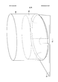
Фиг. 2 иллюстрирует вариант гибко оборачиваемого кристалла интегральной схемы, расположенного вокруг многоуровневого пакета из нескольких кристаллов интегральных схем.FIG. 2 illustrates an embodiment of a flexibly wrapable integrated circuit chip located around a multi-level stack of several integrated circuit chips.
Фиг. 3 иллюстрирует вариант гибко оборачиваемого кристалла интегральной схемы с антенной.FIG. 3 illustrates an embodiment of a flexibly turnable integrated circuit chip with an antenna.
Фиг. 4 иллюстрирует вариант гибко оборачиваемого кристалла интегральной схемы с экраном.FIG. 4 illustrates an embodiment of a flexibly wrapable integrated circuit chip with a screen.
Фиг. 5 иллюстрирует вариант гибко оборачиваемого кристалла интегральной схемы с соединениями по краю.FIG. 5 illustrates an embodiment of a flexibly wrapable integrated circuit chip with edge connections.
Фиг. 6 иллюстрирует вариант способа соединения гибко оборачиваемого кристалла интегральной схемы с другой подложкой.FIG. 6 illustrates an embodiment of a method for connecting a flexibly wrapped integrated circuit chip to another substrate.
Фиг. 7A-7D иллюстрируют варианты многоуровневого соединительного столбика на гибко оборачиваемом кристалле интегральной схемы.FIG. 7A-7D illustrate multi-level interconnect posts on a flexibly wrapable integrated circuit chip.
Фиг. 8 иллюстрирует вариант котировочных столбиков.FIG. 8 illustrates an example of quotation bars.
Подробное описаниеDetailed description
Последующее описание и чертежи в достаточной степени иллюстрируют конкретные варианты, чтобы позволить специалистам в рассматриваемой области реализовать эти варианты на практике. Другие варианты могут содержать структурные, логические, электрические, технологические и другие изменения. Части и признаки некоторых вариантов могут быть включены в или заменять части и признаки других вариантов. Варианты, описываемые Формулой изобретения, охватывают все возможные эквиваленты соответствующих пунктов этой Формулы изобретения.The following description and drawings sufficiently illustrate specific options to enable those skilled in the art to put those options into practice. Other options may include structural, logical, electrical, technological, and other changes. Parts and features of some options may be included in or replace parts and features of other options. The options described by the claims cover all possible equivalents of the corresponding paragraphs of this claims.
Последующее обсуждение относится к кристаллам интегральных схем. Термин «кристалл интегральной схемы» может обозначать не только электрическую схему, но также какую-либо пленку, подложку (например, кремниевую) и/или другой материал, используемый для установки этой схемы. Таким образом, как используется здесь, кристалл термин интегральной схемы может охватывать электрическую схему, выполненную на или в виде части подложки, пленки и/или какого-либо другого подходящего материала для монтажа схемы.The following discussion relates to integrated circuit crystals. The term “integrated circuit crystal” can mean not only an electrical circuit, but also any film, substrate (for example, silicon) and / or other material used to install this circuit. Thus, as used herein, a crystal, an integrated circuit term may encompass an electrical circuit made on or as part of a substrate, film, and / or some other suitable material for mounting the circuit.
Несколько кристаллов интегральных схем могут быть объединены посредством установки их одного над другим в вертикальном направлении в виде многоярусной (этажерочной) структуры. Собранные таким образом кристаллы интегральных схем могут затем использовать сквозные соединения для электрического соединения схемы, расположенной на первом ярусе, со схемами, установленными на других ярусах над и/или под первым ярусом.Several crystals of integrated circuits can be combined by installing them one above the other in the vertical direction in the form of a multi-tiered (shelf) structure. The integrated circuit crystals thus assembled can then use end-to-end connections to electrically connect the circuitry located on the first tier with the circuits mounted on other tiers above and / or below the first tier.
Такая ориентация может привести к тому, что тепло, выделяемое схемой, работающей на нижнем кристалле интегральной схемы, будет распространяться вверх, сквозь расположенные выше кристаллы интегральных схем. При добавлении этого дополнительного теплового потока к теплу, выделяемому собственными схемами на этих, расположенных выше кристаллах интегральных схем могут возникать проблемы, связанные с перегревом, и вследствие этого может возрастать интенсивность отказов схемных компонентов, выполненных на этих верхних кристаллах интегральных схем.This orientation may cause the heat generated by the circuit operating on the lower chip of the integrated circuit to propagate upward through the crystals of the integrated circuit located above. When this additional heat flux is added to the heat generated by the own circuits on these integrated circuit crystals located above, problems associated with overheating can occur, and as a result, the failure rate of the circuit components made on these upper integrated circuit crystals can increase.
Эти проблемы могут быть уменьшены посредством оборачивания относительно тонкого, вертикально ориентированного кристалла интегральной схемы вокруг одного или нескольких горизонтально ориентированных интегральных схем. Например, за счет уменьшения толщины гибко оборачиваемого кристалла интегральной схемы до такой толщины, которая делает этот кристалл гибким и позволяет изогнуть его (например, для кремниевых (Si) кристаллов это толщина меньше 50 мкм; а для других кристаллов или материалов для подложек кристаллов могут действовать другие предельные толщины), такой гибко оборачиваемый кристалл интегральной схемы может быть присоединен в вертикальной ориентации по периферии вокруг краев одного или нескольких горизонтально ориентированных кристаллов интегральных схем. Тепло, генерируемое схемой на таком гибко оборачиваемом кристалле интегральной схемы, может излучаться вверх и прочь от горизонтально ориентированных кристаллов интегральных схем.These problems can be mitigated by wrapping a relatively thin, vertically oriented integrated circuit chip around one or more horizontally oriented integrated circuits. For example, by reducing the thickness of a flexibly wrapped integrated circuit crystal to a thickness that makes this crystal flexible and allows it to be bent (for example, for silicon (Si) crystals this thickness is less than 50 microns; and for other crystals or materials for crystal substrates, other extreme thicknesses), such a flexibly wrapped integrated circuit crystal can be attached in a vertical orientation along the periphery around the edges of one or more horizontally oriented crystals eral circuits. The heat generated by the circuit on such a flexibly wrapped integrated circuit chip can be radiated up and away from horizontally oriented integrated circuit crystals.
Хотя здесь упоминаются вертикально ориентированный, гибко оборачиваемый кристалл интегральной схемы и горизонтально ориентированный кристалл интегральной схемы (а также подложка, к которой прикреплены эти кристаллы), рассматриваемые здесь варианты не ограничиваются точно ортогональным взаимным расположением этих двух кристаллов. Например, вертикально ориентированный гибко оборачиваемый кристалл интегральной схемы может располагаться под углом, отличным от 90°, относительно подложки или корпуса, в котором установлен кристалл, и относительно кристалла(ов) интегральной схемы, вокруг которого может быть обернут этот гибко оборачиваемый кристалл интегральной схемы.Although a vertically oriented, flexibly wrapped integrated circuit crystal and a horizontally oriented integrated circuit crystal (as well as the substrate to which these crystals are attached) are mentioned here, the options considered here are not limited to the precisely orthogonal relative position of the two crystals. For example, a vertically oriented flexibly wrapable chip of an integrated circuit may be located at an angle other than 90 ° with respect to the substrate or housing in which the chip is mounted, and with respect to the chip (s) of the integrated circuit around which this flexibly wrapable chip of the integrated circuit.
Фиг. 1 иллюстрирует устройство с гибко оборачиваемым кристаллом 100 интегральной схемы. Устройство может содержать гибко оборачиваемый кристалл 100 интегральной схемы, установленный на подложке или в корпусе 115.FIG. 1 illustrates a device with a
Такой гибко оборачиваемый кристалл 100 интегральной схемы может иметь уменьшенную толщину, чтобы его можно было согнуть в достаточной степени для образования дуги, сегмента окружности, круга, овала или некоторой другой формы. Этот гибко оборачиваемый кристалл 100 интегральной схемы может содержать схему (например, дорожки, сквозные соединения, электронные компоненты), выполненные в или на части пленки, подложки (например, кремниевой, германиевой) или другого подходящего материала кристалла.Such a flexibly wrapable
Такой гибко оборачиваемый кристалл 100 интегральной схемы может быть установлен в корпусе 115, который может выполнять одну или несколько функций, а именно конструктивную (структурную) защиту, защиту от воздействия факторов окружающей среды, экранирование и/или теплоотвод. Дно корпуса 115 может представлять собой подложку или может быть прикреплено к подложке. Корпус 115 может охватывать устройство с гибко оборачиваемым кристаллом 100 интегральной схемы.Such a flexible wrap-around integrated
Фиг. 1 иллюстрирует также тот факт, что в некоторых вариантах могут не использоваться горизонтально ориентированные кристаллы интегральных схем. Например, гибко оборачиваемый кристалл 100 интегральной схемы может быть свернут по существу так, как показано на этом чертеже, без горизонтально ориентированных кристаллов интегральных схем. В одном из вариантов проволочные перемычки 121 могут соединять схему, выполненную на гибко оборачиваемом кристалле 100 интегральной схемы, с подложкой или корпусом 115, где может быть установлена схема.FIG. 1 also illustrates the fact that, in some embodiments, horizontally oriented integrated circuit crystals may not be used. For example, a flexibly wrapable integrated
Такой гибко оборачиваемый кристалл 100 интегральной схемы может быть свернут в виде полного замкнутого контура, так что концы этого гибко оборачиваемого кристалла 100 интегральной схемы приведены в контакт один с другим и могут быть соединены один с другим. Другие варианты могут содержать зазор между концами гибко оборачиваемого кристалла 100 интегральной схемы, такой как зазор, показанный на Фиг. 1. В таком варианте могут быть использованы одна или несколько проволочных перемычек 120 для соединения цепей через зазор, если нужно замкнуть одну или несколько цепей. В другом варианте гибко оборачиваемый кристалл 100 интегральной схемы может иметь форму только дуги или криволинейную форму.Such a flexibly wrapped
В другом варианте, гибко оборачиваемый кристалл 100 интегральной схемы может иметь сегментированную подложку (например, несколько соединенных один с другим более коротких сегментов), где каждый сегмент может быть недостаточно тонким, чтобы быть гибким по отдельности, но все вместе они могут имитировать гибко оборачиваемый кристалл 100 интегральной схемы. Другой вариант может использовать кристалл 100 интегральной схемы, который сначала является гибким, а потом может быть сделан твердым в дугообразной, криволинейной или круглой форме и более не гнуться после того, как ему придана нужная форма.In another embodiment, the flexibly wrapped
Одна сторона гибко оборачиваемого кристалла 100 интегральной схемы может быть активной стороной 111, тогда как другая сторона может быть неактивной стороной 110. На активной стороне может располагаться большая часть электронной схемы, содержащая схемные дорожки и/или схемные компоненты (например, транзисторы, соединительные элементы, конденсаторы, резисторы, логические элементы). Неактивная сторона 110 может содержать меньшую часть электронной схемы.One side of the flexibly
Фиг. 2 иллюстрирует вариант гибко оборачиваемого кристалл 100 интегральной схемы, расположенного вокруг горизонтально ориентированного кристалла(ов) 200 интегральной схемы (например, стека (многоуровневой структуры) из кристаллов интегральных схем, подложек и/или электрических компонентов. Кристаллы 200 в стеке интегральных схем могут быть соединены один с другим механически и электрически посредством припойных шариковых выводов и проволочных перемычек 205. Сквозные соединения могут электрически соединять схемы на кристаллах и/или подложках с разных ярусов. Если дно корпуса 115 содержит подложку со схемой, горизонтально ориентированный кристалл(ы) 200 может быть соединен с этой схемой посредством одной или нескольких проволочных перемычек 205.FIG. 2 illustrates an embodiment of a flexibly wrapable
Схема на активной стороне 111 гибко оборачиваемого кристалла 100 интегральной схемы может быть соединена с горизонтально ориентированным кристаллом 200 посредством одной или нескольких проволочных перемычек 203. Эта схема на активной стороне 111 гибко оборачиваемого кристалла 100 интегральной схемы может также быть соединена со схемой на подложке и/или на корпусе 115 посредством одной или нескольких проволочных перемычек 121.The circuit on the
Фиг. 3 иллюстрирует вариант гибко оборачиваемого кристалла 100 интегральной схемы, имеющего антенну 300. Антенна 300 может быть смонтирована на неактивной стороне 110 (например, на наружной стороне) гибко оборачиваемого кристалла 100 интегральной схемы. Антенна 300 может быть электрически соединена со схемой на активной стороне 111 посредством сквозного соединения или проволочной перемычки. Антенна 300 может быть электрически соединена с горизонтально ориентированным кристаллом(ами) 200 интегральной схемы посредством проволочной перемычки 310, соединенной со сквозным соединением.FIG. 3 illustrates an embodiment of a flexibly wrapable
Антенна 300 может быть конфигурирована для излучения сигнала наружу, не мешая горизонтально ориентированному кристаллу(ам) 200 интегральной схемы. Это может быть достигнуто посредством создания экранирующего слоя между антенной 300 и неактивной стороной 110 гибко оборачиваемого кристалла 100 интегральной схемы. В одном из вариантов антенна 300 может быть частью экрана 400 или работать во взаимодействии с этим экраном, как показано на Фиг. 4.The
Антенна 300 может быть выполнена из металла и создана на поверхности гибко оборачиваемого кристалла 100 интегральной схемы с использованием травления или осаждения металла. Антенна 300 может также представлять собой антенный элемент, электрически и/или механически прикрепленный к поверхности гибко оборачиваемого кристалла 100 интегральной схемы.
Фиг. 4 иллюстрирует вариант гибко оборачиваемого кристалла 100 интегральной схемы, имеющего экраны 400, 401. Эти экраны 400, 401 могут быть изготовлены из металла и представлять собой экраны, выполненные как на неактивной поверхности 110 гибко оборачиваемого кристалла 100 интегральной схемы, так и на верхней части 401 этого гибко оборачиваемого кристалла 100 интегральной схемы.FIG. 4 illustrates an embodiment of a
В одном из вариантов только на неактивной поверхности 110 гибко оборачиваемого кристалла 100 интегральной схемы выполнен экран 401. В другом варианте только на верхней части 401 этого гибко оборачиваемого кристалла 100 интегральной схемы имеется экран 401. Как обсуждается ранее со ссылками на Фиг. 3, либо верхний экран 401, либо боковой экран 400 может иметь антенну 300, выполненную в экранирующем материале.In one embodiment, a
В некоторых вариантах гибко оборачиваемый кристалл 100 интегральной схемы может быть приклеен, припаян или прикреплен некоторым иным способом к корпусу 115, как показано ранее. Фиг. 5 иллюстрирует вариант гибко оборачиваемого кристалла 100 интегральной схемы, прикрепленного к подложке или корпусу 115 с использованием торцевых соединений.In some embodiments, the flexibly wrapable
Например, к верхней поверхности подложки или корпуса 115 могут быть прикреплены несколько припойных областей (например, припойных шариковых выводов) расположенных по какой-то конкретной схеме. На нижней торцевой поверхности гибко оборачиваемого кристалла 100 интегральной схемы могут быть выполнены несколько контактных площадок 501, расположенных в соответствии с такой же схемой, так что каждая контактная площадка соответствует позиции одного из припойных шариковых выводов. Рассматриваемый гибко оборачиваемый кристалл 100 интегральной схемы можно затем опустить на верхнюю поверхность подложки или корпуса 115 или приблизить к этой поверхности, так что соответствующие контактные площадки 501 совмещаются с припойными шариковыми выводами 500. Когда эту сборку нагревают, припойные шариковые выводы 500 могут расплавиться и затем соединиться при охлаждении с соответствующими контактными площадками, прикрепляя тем самым гибко оборачиваемый кристалл 100 интегральной схемы к подложке или корпусу 115.For example, several solder areas (e.g., solder ball leads) arranged in a particular pattern may be attached to the upper surface of the substrate or
Фиг. 6 иллюстрирует вариант способа соединения гибко оборачиваемого кристалла 100 интегральной схемы с подложкой или корпусом 115, либо с другой подложкой. При сборке может быть применена трубка 600, по существу окружающая гибко оборачиваемый кристалл 100 интегральной схемы, так что либо эта трубка 600 может быть использована временно в процессе прикрепления этого гибко оборачиваемого кристалла 100 интегральной схемы к корпусу 115, либо трубка может быть постоянно прикреплена к подложке или корпусу 115. Трубка 600 может быть использована в процессе монтажа проволочных перемычек для уменьшения растрескивания, которое может возникать в ходе такого монтажа перемычек.FIG. 6 illustrates an embodiment of a method for connecting a flexibly wrapped
Трубка 600 может иметь в составе материал, который позволяет этой трубке служить теплоотводом. Например, трубка 600 может быть либо целиком выполнена из металла, либо ее поверхность может быть покрыта металлом, эта трубка 600 может быть механически соединена с гибко оборачиваемым кристаллом 100 интегральной схемы и излучать тепло прочь от этого кристалла 100 интегральной схемы.
Фиг. 7A-7D иллюстрируют варианты способа создания многоуровневого соединительного столбика 705 на гибко оборачиваемом кристалле 100 интегральной схемы и присоединения проволочной перемычки между этим соединительным столбиком 705 и горизонтально ориентированным кристаллом 710 интегральной схемы. Такой многоуровневый соединительный столбик 705 может уменьшить сложность и повысить надежность процесса монтажа проволочных перемычек, поскольку механизмы для монтажа могут перемещаться только в вертикальном направлении. Однако такой вариант приведен только в качестве иллюстрации, поскольку в другом варианте проволочная перемычка может быть прикреплена к гибко оборачиваемому кристаллу 100 интегральной схемы по существу в горизонтальном направлении.FIG. 7A-7D illustrate variations of a method for creating a
Фиг. 7А иллюстрирует начальный этап, на котором гибко оборачиваемый кристалл 100 интегральной схемы лежит плоско. Этот гибко оборачиваемый кристалл 100 интегральной схемы имеет несколько припойных контактных площадок 700-702. В одном из вариантов несколько припойных контактных площадок 700-702 расположены на активной стороне 111 гибко оборачиваемого кристалла 100 интегральной схемы.FIG. 7A illustrates an initial step in which a flexibly wrapable
Фиг. 7В иллюстрирует многоуровневый столбик (стек) 705 из нескольких припойных шариков (например, припойных шариковых выводов), выполненный на одной из припойных контактных площадок 701. В одном из вариантов вместо нескольких припойных шариков может быть использован металлический цилиндр или один припойный цилиндр.FIG. 7B illustrates a multi-level column (stack) 705 of several solder balls (for example, solder ball leads) made on one of the
Фиг. 7С иллюстрирует гибко оборачиваемый кристалл 100 интегральной схемы, расположенный по существу в вертикальной ориентации и помещенный возле по существу горизонтального кристалла 710 интегральной схемы. Этот по существу горизонтальный кристалл 710 интегральной схемы может иметь несколько припойных контактных площадок 711,712.FIG. 7C illustrates a flexibly wrapable
Фиг. 7D иллюстрирует проволочную перемычку, прикрепленную и к многоуровневому столбику (стеку) 705 и к одной из припойных контактных площадок 711 на по существу горизонтальном кристалле 710 интегральной схемы. Для монтажа проволочных перемычек может быть использован хорошо известный процесс нагрева припоя, наложения на него проволочки и естественного охлаждения припоя.FIG. 7D illustrates a wire jumper attached to both the tiered column (stack) 705 and one of the
Изображенный на Фиг. 7A-7D процесс монтажа проволочных перемычек показан только для целей иллюстрации. Здесь могут быть применены также и другие процессы монтажа проволочных перемычек.Depicted in FIG. 7A-7D, the process of mounting wire jumpers is shown for illustrative purposes only. Here can also be applied other processes for mounting wire jumpers.
Фиг. 8 иллюстрирует вариант котировочных столбиков для выравнивания и совмещения гибко оборачиваемого кристалла 100 интегральной схемы с подложкой или корпусом 115, к которому присоединен этот гибко оборачиваемый кристалл 100 интегральной схемы. Эти котировочные столбики могут представлять собой несколько столбиков 800-803, расположенных в углах корпуса 115. Другие варианты могут быть использовать больше четырех столбиков 800-803 и/или располагать эти столбики в позициях, отличных от углов корпуса 115.FIG. 8 illustrates an example of quotation bars for aligning and aligning a flexibly wrap
В процессе монтажа гибко оборачиваемого кристалла 100 интегральной схемы на другие подложки или в корпусе 115 этот гибко оборачиваемый кристалл 100 интегральной схемы может быть помещен внутри контура, ограниченного котировочными столбиками 800-803. Указанные котировочные столбики 800-803 могут затем удерживать этот гибко оборачиваемый кристалл 100 интегральной схемы в таком положении, пока он не будет постоянно прикреплен к корпусу 115. Например, как показано на Фиг. 5, может быть желательно точное совмещение гибко оборачиваемого кристалла 100 интегральной схемы, чтобы правильно разместить припойные шарики 500 и контактные площадки 501. Столбики 800-803 можно удалить после прикрепления гибко оборачиваемого кристалла 100 интегральной схемы или оставить в корпусе 115 постоянно.During the installation of the flexibly wrapped
Если оставить юстировочные столбики 800-803 постоянно, они могут служить другим целям помимо совмещения. Например, эти юстировочные столбики 800-803 могут служить теплоотводами для удаления тепла от гибко оборачиваемого кристалла 100 интегральной схемы, подложек или корпуса 115. Такие юстировочные столбики 800-803 могут быть также использованы в качестве антенн, для избирательного экранирования и/или для изменения характера воздушного потока (например, воздушного потока от вентилятора охлаждения) вокруг сборки.If you leave the adjustment posts 800-803 constantly, they can serve other purposes besides alignment. For example, these alignment posts 800-803 can be used as heat sinks to remove heat from the flexibly wrapable
Примеры:Examples:
Последующие примеры относятся к дополнительным вариантам.The following examples relate to additional options.
Пример 1 представляет устройство на основе кристалла интегральной схемы, содержащее подложку, к которой прикреплен гибкий кристалл интегральной схемы по существу в вертикальной ориентации относительно поверхности подложки.Example 1 is an integrated circuit chip device containing a substrate to which a flexible integrated circuit chip is attached in a substantially vertical orientation relative to the surface of the substrate.
В Примере 2 предмет Примера 1 может в качестве опции представлять собой имеющий криволинейную форму кристалл интегральной схемы, содержащий сегментированную подложку, составленную из нескольких связанных один с другим сегментов.In Example 2, the subject of Example 1 may optionally be a curved integrated circuit crystal containing a segmented substrate composed of several segments connected to one another.
В Примере 3 предмет Примеров 1-2 может представлять собой в качестве опции имеющий криволинейную форму кристалл интегральной схемы, обладающий активной стороной и неактивной стороной.In Example 3, the subject of Examples 1-2 can be an optional integrated circuit crystal having a curved shape, having an active side and an inactive side.
В Примере 4 предмет Примеров 1-3 может в качестве опции иметь кристалл, в котором на активной стороне находится дополнительная электронная схема относительно неактивной стороны.In Example 4, the subject of Examples 1-3 may optionally have a crystal in which there is an additional electronic circuit on the inactive side on the active side.
В Примере 5 предмет Примеров 1-4 может в качестве опции содержать проволочные перемычки, соединяющие электронную схему на имеющем криволинейную форму кристалле интегральной схеме со схемой на подложке.In Example 5, the subject of Examples 1-4 may optionally include wire jumpers connecting an electronic circuit on a curved crystal to an integrated circuit with a circuit on a substrate.
В Примере 6 предмет Примеров 1-5 может в качестве опции содержать по меньшей мере один кристалл интегральной схемы, соединенный с подложкой, расположенной по существу в горизонтальной ориентации относительно этого гибкого кристалла интегральной схемы, где этот имеющий криволинейную форму кристалл интегральной схемы обернут вокруг по меньшей мере части периферии указанного по меньшей мере одного кристалла интегральной схемы.In Example 6, the subject of Examples 1-5 may optionally comprise at least one integrated circuit chip connected to a substrate arranged substantially horizontally relative to this flexible integrated circuit chip, where this curved integrated circuit chip is wrapped around at least as part of the periphery of the at least one integrated circuit chip.
В Примере 7 предмет Примеров 1-6 может содержать соединение электронной схемы, выполненной на имеющем криволинейную форму кристалле интегральной схемы, посредством одной или нескольких проволочных перемычек с указанным по меньшей мере одним кристаллом интегральной схемы.In Example 7, the subject of Examples 1-6 may comprise connecting an electronic circuit arranged on a curved crystal of an integrated circuit using one or more wire jumpers with said at least one integrated circuit chip.
В Примере 8 предмет Примеров 1-7 может в качестве опции содержать соединение имеющего криволинейную форму кристалла интегральной схемы с подложкой по круговой схеме вокруг периферии указанного по меньшей мере одного кристалла интегральной схемы.In Example 8, the subject of Examples 1-7 may optionally comprise connecting a curved integrated circuit chip to a substrate in a circular pattern around the periphery of the at least one integrated circuit chip.
В Примере 9 в предмете Примеров 1-8 концы имеющего криволинейную форму кристалла интегральной схемы в качестве опции соединены один с другим.In Example 9, in the subject of Examples 1-8, the ends of a curved crystal of an integrated circuit are optionally connected to one another.
В Примере 10 предмет Примеров 1-9 может в качестве опции содержать экран, выполненный на неактивной стороне имеющего криволинейную форму кристалла интегральной схемы.In Example 10, the subject of Examples 1 to 9 may optionally comprise a screen made on the inactive side of an integrated circuit crystal having a curved shape.
Пример 11 представляет собой устройство на основе гибко оборачиваемого кристалла интегральной схемы, содержащее: подложку, прикрепленный к подложке кристалл интегральной схемы и гибкий кристалл интегральной схемы, этот гибкий кристалл интегральной схемы соединен с подложкой в по существу вертикальной ориентации относительно поверхности подложки, так что гибкий кристалл интегральной схемы по существу окружает расположенный на подложке кристалл интегральной схемы по периферии.Example 11 is a device based on a flexibly wrapable integrated circuit chip, comprising: a substrate attached to a substrate an integrated circuit chip and a flexible integrated circuit chip, this flexible integrated circuit chip is connected to the substrate in a substantially vertical orientation relative to the surface of the substrate, so that the flexible crystal the integrated circuit essentially surrounds a peripheral integrated circuit chip located on the substrate.
В Примере 12 предмет Примера 11 может в качестве опции иметь соединенный с подложкой кристалл интегральной схемы, содержащий несколько расположенных в виде пакета (стека) один над другим кристаллов интегральных схем.In Example 12, the subject of Example 11 may optionally have an integrated circuit chip connected to a substrate, containing several integrated circuit crystals arranged in a packet (stack) one above the other.
В Примере 13 предмет Примеров 11-12 может в качестве опции содержать трубку, соединенную с подложкой и по существу окружающую гибкий кристалл интегральной схемы.In Example 13, the subject of Examples 11-12 may optionally comprise a tube connected to a substrate and substantially surrounding a flexible integrated circuit chip.
В Примере 14 предмет Примеров 11-13 может в качестве опции содержать гибкий кристалл интегральной схемы, дополнительно имеющий несколько контактных площадок, расположенных по нижнему краю гибкого кристалла интегральной схемы в соответствии с конкретной схемой, каждая из этих контактных площадок соединена с соответствующим припойным шариком из группы прикрепленных к подложке припойных шариков, расположенных в соответствии с конкретной схемой.In Example 14, the subject of Examples 11-13 may optionally comprise a flexible integrated circuit chip, additionally having several pads located on the lower edge of the flexible integrated circuit chip in accordance with a specific circuit, each of these pads connected to a corresponding solder ball from the group solder balls attached to the substrate, arranged in accordance with a specific pattern.
В Примере 15 в предмете Примеров 11-14 в качестве опции подложка может представлять собой часть корпуса, по существу окружающую устройство на основе гибко оборачиваемого кристалла интегральной схемы.In Example 15, in the subject of Examples 11-14, as an option, the substrate may be a part of a housing substantially surrounding a device based on a flexibly wrapped integrated circuit chip.
В Примере 16 предмет Примеров 11-15 может в качестве опции содержать юстировочные столбики, соединенные с подложкой и конфигурированные для совмещения гибкого кристалла интегральной схемы с подложкой.In Example 16, the subject of Examples 11-15 may optionally include alignment posts connected to the substrate and configured to align the flexible chip of the integrated circuit with the substrate.
Пример 17 представляет способ монтажа гибко оборачиваемого кристалла интегральной схемы на подложку, способ содержит: создание нескольких припойных областей, расположенных по конкретной схеме на этой подложке; совмещение каждой из указанных нескольких контактных площадок, расположенных по указанной схеме на нижней торцевой поверхности гибко оборачиваемого кристалла интегральной схемы, с соответствующей из нескольких припойных областей; и сплавление каждой из указанных нескольких контактных площадок с соответствующей одной из нескольких припойных областей.Example 17 presents a method for mounting a flexibly wrapped integrated circuit chip on a substrate, the method comprising: creating several solder regions arranged according to a specific circuit on this substrate; the combination of each of these several contact pads located according to the specified circuit on the lower end surface of the flexibly wrapped crystal of the integrated circuit with the corresponding of several solder areas; and fusing each of these several contact pads with a corresponding one of several solder areas.
В Примере 18 предмет Примера 17 может в качестве опции содержать создание многоуровневых (многослойных) столбиков на гибко оборачиваемом кристалле интегральной схемы; и прикрепление проволочных перемычек между этими многоуровневыми столбиками и подложкой.In Example 18, the subject of Example 17 may optionally comprise the creation of multi-level (multi-layer) columns on a flexibly wrapped integrated circuit chip; and attaching wire jumpers between these tiered posts and the substrate.
В Примере 19 предмет Примеров 17-18 может в качестве опции содержать создание указанных многослойных столбиков путем укладки один на другой нескольких припойных шариков на припойную площадку гибко оборачиваемого кристалла интегральной схемы.In Example 19, the subject of Examples 17-18 may optionally comprise the creation of said multilayer columns by stacking several solder balls on top of each other on a solder pad of a flexibly wrapped integrated circuit chip.
В Примере 20 предмет Примеров 17-19 может в качестве опции содержать совмещение каждой из нескольких контактных площадок с использованием котировочных столбиков, установленных на подложке, для совмещения гибко оборачиваемого кристалла интегральной схемы с расположенными на подложке в соответствии с указанной конкретной схемой припойными областями.In Example 20, the subject of Examples 17-19 may optionally contain a combination of each of several pads using quotation columns mounted on a substrate to combine a flexibly wrapable integrated circuit chip with solder areas located on the substrate in accordance with the specified specific circuit.
В Примере 21 предмет Примеров 17-20 может в качестве опции использовать для совмещения каждой из нескольких контактных площадок формование гибко оборачиваемого кристалла интегральной схемы внутри трубки, прикрепленной к подложке.In Example 21, the subject of Examples 17-20 can optionally use the formation of a flexibly wrapable integrated circuit chip inside a tube attached to a substrate to align each of several pads.
В Примере 22 предмет Примеров 17-21 может в качестве опции содержать соединение концов гибкого кристалла интегральной схемы одно с другим посредством одной или нескольких проволочных перемычек.In Example 22, the subject of Examples 17-21 may optionally comprise connecting the ends of the flexible crystal of the integrated circuit to one another by means of one or more wire jumpers.
Пример 23 представляет устройство на основе гибко оборачиваемого кристалла интегральной схемы, содержащее: корпус, имеющий подложку на нижней поверхности; гибкий кристалл интегральной схемы, так что этот гибкий кристалл интегральной схемы присоединен к подложке по существу в вертикальной ориентации относительно поверхности этой подложки; и экран, соединенный с указанным гибким кристаллом интегральной схемы.Example 23 is a device based on a flexible wrap chip integrated circuit, comprising: a housing having a substrate on a lower surface; a flexible integrated circuit chip so that this flexible integrated circuit chip is attached to the substrate in a substantially vertical orientation relative to the surface of that substrate; and a screen coupled to said flexible integrated circuit chip.
В Примере 24 предмет Примера 23 может в качестве опции содержать корпус, по существу окружающий гибкий кристалл интегральной схемы.In Example 24, the subject of Example 23 may optionally comprise a housing substantially surrounding a flexible integrated circuit chip.
В Примере 25 предмет Примеров 23-24 может в качестве опции содержать корпус, способный отводить тепло.In Example 25, the subject of Examples 23-24 may optionally include a housing capable of dissipating heat.
В Примере 26 предмет Примеров 23-25 может в качестве опции содержать корпус, имеющий возможности экранирования.In Example 26, the subject of Examples 23-25 may optionally comprise a housing having shielding capabilities.
В Примере 27 предмет Примеров 23-26 может в качестве опции содержать экран, обернутый вокруг гибкого кристалла интегральной схемы на неактивной стороне гибкого кристалла интегральной схемы.In Example 27, the subject of Examples 23-26 may optionally comprise a screen wrapped around a flexible chip of an integrated circuit on the inactive side of a flexible chip of an integrated circuit.
В Примере 28 предмет Примеров 23-27 может в качестве опции содержать верхний экран, соединенный с верхним краем экрана, обернутого вокруг гибкого кристалла интегральной схемы.In Example 28, the subject of Examples 23-27 may optionally comprise a top screen connected to the top edge of the screen wrapped around a flexible integrated circuit chip.
В Примере 29 предмет Примеров 23-28 может в качестве опции содержать юстировочные столбики, прикрепленные к подложке, эти юстировочные столбики способны отводить тепло.In Example 29, the subject of Examples 23-28 may optionally include adjustment posts attached to the substrate, these adjustment posts capable of dissipating heat.
В Примере 30 предмет Примеров 23-29 может в качестве опции содержать юстировочные столбики, прикрепленные к подложке, так что по меньшей мере на одном из этих котировочных столбиков имеется антенна.In Example 30, the subject of Examples 23-29 may optionally include adjustment posts attached to the substrate, so that at least one of these quote posts has an antenna.
В Примере 31 предмет Примеров 23-30 может в качестве опции содержать юстировочные столбики, прикрепленные к подложке, так что эти юстировочные столбики конфигурированы для направления потока охлаждающего воздуха вокруг устройства.In Example 31, the subject of Examples 23-30 may optionally include adjustment columns attached to the substrate, so that these adjustment columns are configured to direct the flow of cooling air around the device.
Пример 32 представляет устройство на основе гибко оборачиваемого кристалла интегральной схемы, содержащее: корпус, имеющий подложку на нижней поверхности; первые средства для монтажа, соединенные с некой схемой на верхней поверхности подложки; и гибкий кристалл интегральной схемы, имеющий вторые средства для монтажа, расположенные по нижнему краю в соответствии с указанной схемой, так что каждое из вторых средств для монтажа соответствует одному из первых средств для монтажа, гибкий кристалл интегральной схемы соединен с подложкой по существу в вертикальной ориентации относительно первой поверхности подложки.Example 32 is a device based on a flexible wrap chip integrated circuit, comprising: a housing having a substrate on a lower surface; the first means for installation, connected to a certain circuit on the upper surface of the substrate; and a flexible integrated circuit chip having second mounting means located at a lower edge in accordance with said circuit, so that each of the second mounting means corresponds to one of the first mounting means, the flexible integrated circuit chip is connected to the substrate in a substantially vertical orientation relative to the first surface of the substrate.
В Примере 33 предмет Примера 32 может в качестве опции содержать первые средства для монтажа, представляющие собой несколько припойных шариков, и вторые средства для монтажа, представляющие собой несколько контактных площадок.In Example 33, the subject of Example 32 may optionally contain first mounting means, which are several solder balls, and second mounting means, which are several pads.
В Примере 34 предмет Примеров 32-33 может в качестве опции содержать гибкий кристалл интегральной схемы, имеющий толщину в диапазоне 2-25 мм.In Example 34, the subject of Examples 32-33 may optionally contain a flexible integrated circuit chip having a thickness in the range of 2-25 mm.
В Примере 35 предмет Примеров 32-34 может в качестве опции содержать гибкий кристалл интегральной схемы, имеющий антенну.In Example 35, the subject of Examples 32-34 may optionally comprise a flexible integrated circuit chip having an antenna.
Claims (39)
Applications Claiming Priority (1)
| Application Number | Priority Date | Filing Date | Title |
|---|---|---|---|
| PCT/US2013/076397 WO2015094259A1 (en) | 2013-12-19 | 2013-12-19 | Flexibly-wrapped integrated circuit die |
Publications (2)
| Publication Number | Publication Date |
|---|---|
| RU2016119458A RU2016119458A (en) | 2017-11-23 |
| RU2642170C2 true RU2642170C2 (en) | 2018-01-24 |
Family
ID=53275444
Family Applications (1)
| Application Number | Title | Priority Date | Filing Date |
|---|---|---|---|
| RU2016119458A RU2642170C2 (en) | 2013-12-19 | 2013-12-19 | Flexibly wrapped crystal of integrated circuit |
Country Status (8)
| Country | Link |
|---|---|
| US (2) | US9515049B2 (en) |
| EP (1) | EP3084824A4 (en) |
| JP (1) | JP6167375B2 (en) |
| KR (1) | KR101833155B1 (en) |
| CN (1) | CN106030781B (en) |
| DE (1) | DE102014116930A1 (en) |
| RU (1) | RU2642170C2 (en) |
| WO (1) | WO2015094259A1 (en) |
Families Citing this family (4)
| Publication number | Priority date | Publication date | Assignee | Title |
|---|---|---|---|---|
| RU2642170C2 (en) | 2013-12-19 | 2018-01-24 | Интел Корпорейшн | Flexibly wrapped crystal of integrated circuit |
| US10396038B2 (en) | 2014-09-26 | 2019-08-27 | Intel Corporation | Flexible packaging architecture |
| GB2566029B (en) * | 2017-08-30 | 2022-11-02 | Pragmatic Printing Ltd | Methods and apparatus for manufacturing a plurality of electronic circuits |
| US11798901B1 (en) | 2018-10-31 | 2023-10-24 | Avery Dennison Retail Information Services Llc | Wafer-scale integration with alternative technology wafer processes that can be folded into three-dimensional packaging |
Citations (4)
| Publication number | Priority date | Publication date | Assignee | Title |
|---|---|---|---|---|
| JP2001284564A (en) * | 2000-01-27 | 2001-10-12 | Sony Corp | Imaging device, method of manufacturing the same, and camera system |
| US20100112774A1 (en) * | 2008-10-30 | 2010-05-06 | Gyuhwan Oh | Variable Resistance Memory Device and Methods of Forming the Same |
| US20110057284A1 (en) * | 2009-09-07 | 2011-03-10 | Stmicroelectronics (Research & Development) Limited | Cmos image sensor having a curved semiconductor chip |
| US20110281407A1 (en) * | 2003-07-21 | 2011-11-17 | Leonard Forbes | Strained semiconductor by full wafer bonding |
Family Cites Families (25)
| Publication number | Priority date | Publication date | Assignee | Title |
|---|---|---|---|---|
| NL6714336A (en) | 1967-10-21 | 1969-04-23 | ||
| US3755891A (en) * | 1971-06-03 | 1973-09-04 | S Hawkins | Three dimensional circuit modules for thick-film circuits and the like and methods for making same |
| JPS5228067U (en) * | 1975-08-20 | 1977-02-26 | ||
| JPS60109358U (en) * | 1983-12-28 | 1985-07-25 | アルプス電気株式会社 | Block board connection structure |
| US4810917A (en) * | 1985-05-28 | 1989-03-07 | Autotech Corporation | Digital resolver/encoder assembly |
| JPH0770681B2 (en) * | 1990-03-29 | 1995-07-31 | 三洋電機株式会社 | Hybrid integrated circuit device |
| JP2894071B2 (en) * | 1992-03-09 | 1999-05-24 | 株式会社日立製作所 | Semiconductor device |
| JPH08102586A (en) * | 1994-09-30 | 1996-04-16 | Sanyo Electric Co Ltd | Hybrid integrated circuit device |
| JPH08321580A (en) * | 1995-05-25 | 1996-12-03 | Rohm Co Ltd | Structure and manufacture fo hybrid integrated circuit device |
| SE9900164D0 (en) * | 1999-01-20 | 1999-01-20 | Piezomotors Uppsala Ab | Flexible microsystem and building techniques |
| US6617671B1 (en) * | 1999-06-10 | 2003-09-09 | Micron Technology, Inc. | High density stackable and flexible substrate-based semiconductor device modules |
| JP4321926B2 (en) * | 1999-10-19 | 2009-08-26 | 富士通株式会社 | Semiconductor device, semiconductor integrated device and manufacturing method thereof |
| JP3580749B2 (en) | 2000-02-18 | 2004-10-27 | シャープ株式会社 | Mounting method of granular semiconductor device |
| JP3265301B2 (en) * | 2000-06-05 | 2002-03-11 | 株式会社東芝 | Semiconductor device and manufacturing method thereof |
| JP4439090B2 (en) * | 2000-07-26 | 2010-03-24 | 日本テキサス・インスツルメンツ株式会社 | Semiconductor device and manufacturing method thereof |
| JP3822040B2 (en) * | 2000-08-31 | 2006-09-13 | 株式会社ルネサステクノロジ | Electronic device and manufacturing method thereof |
| JP2003347355A (en) * | 2002-05-28 | 2003-12-05 | Matsushita Electric Works Ltd | Mounting structure of semiconductor chip |
| CN100401486C (en) * | 2002-08-09 | 2008-07-09 | 富士通株式会社 | Semiconductor device and manufacturing method thereof |
| JP2005183498A (en) * | 2003-12-17 | 2005-07-07 | Fuji Electric Device Technology Co Ltd | MOS type semiconductor device and method of manufacturing the semiconductor device |
| KR100655218B1 (en) * | 2005-07-01 | 2006-12-08 | 삼성전자주식회사 | 3D semiconductor module with a polygonal ground block |
| US7972650B1 (en) * | 2005-07-13 | 2011-07-05 | Nscrypt, Inc. | Method for manufacturing 3D circuits from bare die or packaged IC chips by microdispensed interconnections |
| KR20100058909A (en) * | 2008-11-25 | 2010-06-04 | 삼성전자주식회사 | Method of forming resistance changable memory device |
| AU2011367826B2 (en) | 2011-05-06 | 2015-12-17 | Iridium Medical Technology Co., Ltd. | Non-planar chip assembly |
| GB201210151D0 (en) * | 2012-06-08 | 2012-07-25 | Wfs Technologies Ltd | Antenna system |
| RU2642170C2 (en) | 2013-12-19 | 2018-01-24 | Интел Корпорейшн | Flexibly wrapped crystal of integrated circuit |
-
2013
- 2013-12-19 RU RU2016119458A patent/RU2642170C2/en not_active IP Right Cessation
- 2013-12-19 EP EP13899411.6A patent/EP3084824A4/en not_active Ceased
- 2013-12-19 CN CN201380081060.4A patent/CN106030781B/en active Active
- 2013-12-19 KR KR1020167013079A patent/KR101833155B1/en active IP Right Grant
- 2013-12-19 US US14/368,434 patent/US9515049B2/en not_active Expired - Fee Related
- 2013-12-19 WO PCT/US2013/076397 patent/WO2015094259A1/en active Application Filing
- 2013-12-19 JP JP2016531017A patent/JP6167375B2/en active Active
-
2014
- 2014-11-19 DE DE102014116930.1A patent/DE102014116930A1/en not_active Ceased
-
2016
- 2016-12-02 US US15/367,645 patent/US20170084578A1/en not_active Abandoned
Patent Citations (4)
| Publication number | Priority date | Publication date | Assignee | Title |
|---|---|---|---|---|
| JP2001284564A (en) * | 2000-01-27 | 2001-10-12 | Sony Corp | Imaging device, method of manufacturing the same, and camera system |
| US20110281407A1 (en) * | 2003-07-21 | 2011-11-17 | Leonard Forbes | Strained semiconductor by full wafer bonding |
| US20100112774A1 (en) * | 2008-10-30 | 2010-05-06 | Gyuhwan Oh | Variable Resistance Memory Device and Methods of Forming the Same |
| US20110057284A1 (en) * | 2009-09-07 | 2011-03-10 | Stmicroelectronics (Research & Development) Limited | Cmos image sensor having a curved semiconductor chip |
Also Published As
| Publication number | Publication date |
|---|---|
| KR101833155B1 (en) | 2018-02-27 |
| WO2015094259A1 (en) | 2015-06-25 |
| JP6167375B2 (en) | 2017-07-26 |
| DE102014116930A1 (en) | 2015-06-25 |
| KR20160074586A (en) | 2016-06-28 |
| CN106030781A (en) | 2016-10-12 |
| US20170084578A1 (en) | 2017-03-23 |
| EP3084824A1 (en) | 2016-10-26 |
| CN106030781B (en) | 2019-06-14 |
| JP2016537814A (en) | 2016-12-01 |
| RU2016119458A (en) | 2017-11-23 |
| US9515049B2 (en) | 2016-12-06 |
| EP3084824A4 (en) | 2017-08-16 |
| US20150214188A1 (en) | 2015-07-30 |
Similar Documents
| Publication | Publication Date | Title |
|---|---|---|
| KR100765478B1 (en) | Tape wiring board with holes formed therein, tape package and flat panel display using the same | |
| US7911050B2 (en) | Semiconductor device and method for manufacturing the same | |
| TWI551198B (en) | Printed circuit board structure with heat dissipation function | |
| TWI499017B (en) | Epoxy bump for overhang die | |
| KR101566593B1 (en) | Semiconductor package | |
| RU2642170C2 (en) | Flexibly wrapped crystal of integrated circuit | |
| TW201250957A (en) | Reinforced fan-out wafer-level package | |
| CN103582945A (en) | Semiconductor device | |
| JP5207477B2 (en) | COF type semiconductor package with heat dissipation member | |
| JP2003023035A (en) | Semiconductor device | |
| JP2001196529A (en) | Semiconductor device and wiring method therefor | |
| US20170236804A1 (en) | Apparatuses and methods for internal heat spreading for packaged semiconductor die | |
| KR20150136393A (en) | Flip chip package having chip fixing structure | |
| KR20140073711A (en) | Multi chip package | |
| US10964627B2 (en) | Integrated electronic device having a dissipative package, in particular dual side cooling package | |
| JP2004289156A (en) | Recessed bonded semiconductor package substrate | |
| CN110277355A (en) | Thin Film Flip Chip Packaging | |
| KR101279469B1 (en) | Cof package having improved heat dissipation | |
| CN111106097B (en) | Chip-on-Film Package | |
| JP5171720B2 (en) | Semiconductor device | |
| TW202114487A (en) | Printed circuit board structure having landing pad and printed circuit board structure | |
| WO2009153912A1 (en) | Semiconductor device and method for manufacturing semiconductor device | |
| US11404360B2 (en) | Power module with enhanced heat dissipation | |
| US20240222310A1 (en) | Semiconductor package for stress isolation | |
| KR20190032097A (en) | Chip-on-film package |
Legal Events
| Date | Code | Title | Description |
|---|---|---|---|
| MM4A | The patent is invalid due to non-payment of fees |
Effective date: 20191220 |