KR20150084679A - System and method for a directional coupler - Google Patents
System and method for a directional coupler Download PDFInfo
- Publication number
- KR20150084679A KR20150084679A KR1020150006427A KR20150006427A KR20150084679A KR 20150084679 A KR20150084679 A KR 20150084679A KR 1020150006427 A KR1020150006427 A KR 1020150006427A KR 20150006427 A KR20150006427 A KR 20150006427A KR 20150084679 A KR20150084679 A KR 20150084679A
- Authority
- KR
- South Korea
- Prior art keywords
- circuit
- coupled
- adjustable
- output terminal
- directional coupler
- Prior art date
- Legal status (The legal status is an assumption and is not a legal conclusion. Google has not performed a legal analysis and makes no representation as to the accuracy of the status listed.)
- Granted
Links
- 238000000034 method Methods 0.000 title claims description 53
- 230000008878 coupling Effects 0.000 claims abstract description 47
- 238000010168 coupling process Methods 0.000 claims abstract description 47
- 238000005859 coupling reaction Methods 0.000 claims abstract description 47
- 230000005540 biological transmission Effects 0.000 claims abstract description 36
- 239000003990 capacitor Substances 0.000 claims description 36
- 238000004804 winding Methods 0.000 claims description 21
- 238000005259 measurement Methods 0.000 claims description 14
- 230000010363 phase shift Effects 0.000 claims description 8
- 230000001902 propagating effect Effects 0.000 claims description 8
- 230000004044 response Effects 0.000 claims description 6
- 238000012546 transfer Methods 0.000 claims description 5
- 238000010586 diagram Methods 0.000 description 4
- 230000006870 function Effects 0.000 description 4
- 238000002847 impedance measurement Methods 0.000 description 4
- 230000008901 benefit Effects 0.000 description 3
- 230000003071 parasitic effect Effects 0.000 description 3
- 238000012360 testing method Methods 0.000 description 3
- 230000001413 cellular effect Effects 0.000 description 2
- 239000000463 material Substances 0.000 description 2
- 230000008569 process Effects 0.000 description 2
- 230000000644 propagated effect Effects 0.000 description 2
- 238000001514 detection method Methods 0.000 description 1
- 238000002955 isolation Methods 0.000 description 1
- 238000012986 modification Methods 0.000 description 1
- 230000004048 modification Effects 0.000 description 1
- 238000012544 monitoring process Methods 0.000 description 1
- 238000005457 optimization Methods 0.000 description 1
- 239000004065 semiconductor Substances 0.000 description 1
Images


Classifications
-
- H—ELECTRICITY
- H01—ELECTRIC ELEMENTS
- H01P—WAVEGUIDES; RESONATORS, LINES, OR OTHER DEVICES OF THE WAVEGUIDE TYPE
- H01P5/00—Coupling devices of the waveguide type
- H01P5/12—Coupling devices having more than two ports
- H01P5/16—Conjugate devices, i.e. devices having at least one port decoupled from one other port
- H01P5/18—Conjugate devices, i.e. devices having at least one port decoupled from one other port consisting of two coupled guides, e.g. directional couplers
-
- H—ELECTRICITY
- H04—ELECTRIC COMMUNICATION TECHNIQUE
- H04B—TRANSMISSION
- H04B1/00—Details of transmission systems, not covered by a single one of groups H04B3/00 - H04B13/00; Details of transmission systems not characterised by the medium used for transmission
- H04B1/38—Transceivers, i.e. devices in which transmitter and receiver form a structural unit and in which at least one part is used for functions of transmitting and receiving
- H04B1/40—Circuits
- H04B1/54—Circuits using the same frequency for two directions of communication
- H04B1/58—Hybrid arrangements, i.e. arrangements for transition from single-path two-direction transmission to single-direction transmission on each of two paths or vice versa
- H04B1/581—Hybrid arrangements, i.e. arrangements for transition from single-path two-direction transmission to single-direction transmission on each of two paths or vice versa using a transformer
-
- G—PHYSICS
- G01—MEASURING; TESTING
- G01R—MEASURING ELECTRIC VARIABLES; MEASURING MAGNETIC VARIABLES
- G01R21/00—Arrangements for measuring electric power or power factor
- G01R21/06—Arrangements for measuring electric power or power factor by measuring current and voltage
- G01R21/07—Arrangements for measuring electric power or power factor by measuring current and voltage in circuits having distributed constants
-
- G—PHYSICS
- G01—MEASURING; TESTING
- G01R—MEASURING ELECTRIC VARIABLES; MEASURING MAGNETIC VARIABLES
- G01R1/00—Details of instruments or arrangements of the types included in groups G01R5/00 - G01R13/00 and G01R31/00
- G01R1/20—Modifications of basic electric elements for use in electric measuring instruments; Structural combinations of such elements with such instruments
- G01R1/203—Resistors used for electric measuring, e.g. decade resistors standards, resistors for comparators, series resistors, shunts
-
- G—PHYSICS
- G01—MEASURING; TESTING
- G01R—MEASURING ELECTRIC VARIABLES; MEASURING MAGNETIC VARIABLES
- G01R1/00—Details of instruments or arrangements of the types included in groups G01R5/00 - G01R13/00 and G01R31/00
- G01R1/20—Modifications of basic electric elements for use in electric measuring instruments; Structural combinations of such elements with such instruments
- G01R1/206—Switches for connection of measuring instruments or electric motors to measuring loads
-
- G—PHYSICS
- G01—MEASURING; TESTING
- G01R—MEASURING ELECTRIC VARIABLES; MEASURING MAGNETIC VARIABLES
- G01R19/00—Arrangements for measuring currents or voltages or for indicating presence or sign thereof
-
- H—ELECTRICITY
- H01—ELECTRIC ELEMENTS
- H01P—WAVEGUIDES; RESONATORS, LINES, OR OTHER DEVICES OF THE WAVEGUIDE TYPE
- H01P5/00—Coupling devices of the waveguide type
- H01P5/04—Coupling devices of the waveguide type with variable factor of coupling
-
- H—ELECTRICITY
- H03—ELECTRONIC CIRCUITRY
- H03H—IMPEDANCE NETWORKS, e.g. RESONANT CIRCUITS; RESONATORS
- H03H7/00—Multiple-port networks comprising only passive electrical elements as network components
- H03H7/38—Impedance-matching networks
-
- H—ELECTRICITY
- H03—ELECTRONIC CIRCUITRY
- H03H—IMPEDANCE NETWORKS, e.g. RESONANT CIRCUITS; RESONATORS
- H03H7/00—Multiple-port networks comprising only passive electrical elements as network components
- H03H7/48—Networks for connecting several sources or loads, working on the same frequency or frequency band, to a common load or source
Landscapes
- Physics & Mathematics (AREA)
- General Physics & Mathematics (AREA)
- Engineering & Computer Science (AREA)
- Power Engineering (AREA)
- Computer Networks & Wireless Communication (AREA)
- Signal Processing (AREA)
- Transmitters (AREA)
- Measurement Of Resistance Or Impedance (AREA)
Abstract
실시예에 따라, 회로는, 입력 포트에 결합되는 전류 입력 단자, 전송 포트에 결합되는 전류 출력 단자, 및 전류 입력 단자와 전류 출력 단자 사이에 흐르는 전류에 비례하는 전류 감지 신호를 제공하도록 구성된 전류 감지 출력 단자를 포함한 전류 감지 회로를 포함한다. 회로는 전송 포트에 결합되는 전압 입력 단자와, 전송 포트에서의 전압에 비례하는 전압 감지 신호를 제공하도록 구성된 전압 감지 출력 단자를 갖는 전압 감지 회로를 더 포함한다. 결합 회로는 전류 감지 출력 단자에 결합되는 제 1 입력과, 전압 감지 출력 단자에 결합되는 제 2 입력과, 출력 포트에 결합되는 결합된 출력 노드를 갖는다.According to an embodiment, the circuit includes a current input terminal coupled to the input port, a current output terminal coupled to the transmission port, and a current sense circuit configured to provide a current sense signal proportional to the current flowing between the current input terminal and the current output terminal. And a current sensing circuit including an output terminal. The circuit further includes a voltage sensing circuit having a voltage input terminal coupled to the transmission port and a voltage sensing output terminal configured to provide a voltage sensing signal proportional to the voltage at the transmission port. The coupling circuit has a first input coupled to the current sense output terminal, a second input coupled to the voltage sense output terminal, and a coupled output node coupled to the output port.
Description
본 개시는 일반적으로 전자 디바이스에 관한 것이고, 더 구체적으로는 지향성 커플러를 위한 시스템 및 방법에 관한 것이다.
The present disclosure relates generally to electronic devices, and more particularly to a system and method for a directional coupler.
지향성 커플러는, 특정 방향으로 전송되는 전력을 검출할 수 있는 전자 디바이스이고, 다양한 무선 주파수(RF) 회로에서 사용된다. 예를 들어, 지향성 커플러는 반사된 전파로부터 입사된 전파를 분리함으로써 반사된 전파를 검출하는 레이더 시스템에서 사용될 수 있거나, 전송 라인의 임피던스 부정합을 측정하는 회로에서 사용될 수 있다. 기능적으로, 지향성 커플러는 포워드 전송 경로 및 결합되는 전송 경로를 갖는다. 포워드 전송 경로는 일반적으로 저손실을 갖지만, 반면 결합되는 전송 경로는 특정 방향으로 전파되는 전송 전력의 부분을 결합한다. 전자력 결합 및 자기 커플러를 포함하는 많은 상이한 타입의 커플러 구조가 존재한다. 이들 커플러 타입의 각각은 동작 주파수 및 동작 환경에 따라 상이한 토폴로지 및 재료를 사용하여 구현될 수 있다.A directional coupler is an electronic device capable of detecting power transmitted in a specific direction and is used in various radio frequency (RF) circuits. For example, the directional coupler can be used in a radar system that detects reflected waves by separating the received wave from reflected waves, or it can be used in a circuit that measures the impedance mismatch of a transmission line. Functionally, the directional coupler has a forward transmission path and a combined transmission path. The forward transmission path generally has a low loss, while the coupled transmission path combines the portion of the transmission power that propagates in a particular direction. There are many different types of coupler structures, including electromagnetic coupling and magnetic couplers. Each of these coupler types may be implemented using different topologies and materials depending on operating frequency and operating environment.
예를 들어, 지향성 커플러는 인쇄 회로 보드(a printed circuit board;PCB) 또는 트랜스포머 상에 배치된 스트립라인 구조를 사용하여 구현될 수 있다. 일부 스트립라인 구현에서, 다양한 회로 요소는 측정되는 특정 신호의 1/4 파장 길이가 될 수 있다. 많은 셀룰러 전화기가 동작하는 주파수 범위를 커버하는 500MHz와 3.8GHz 사이의 주파수에서 동작하는 애플리케이션들에 있어서, 집적 회로 상의 피처 크기보다 더 긴 이들 주파수에서의 파장에 대해 집적 회로 상에 스트립라인 지향성 커플러를 구성하는 것은 도전과제가 될 수 있다. 저손실 자기 기반 지향성 커플러는 또한 트랜스포머 손실 및 기생 때문에 이 주파수 범위에서 구성하는 것이 도전과제이다.
For example, the directional coupler may be implemented using a strip line structure disposed on a printed circuit board (PCB) or a transformer. In some stripline implementations, the various circuit elements may be one quarter wavelength long of the particular signal being measured. For applications operating at frequencies between 500 MHz and 3.8 GHz covering the frequency range in which many cellular telephones operate, a strip line directional coupler is provided on the integrated circuit for wavelengths at these frequencies that are longer than the feature size on the integrated circuit Configuring it can be a challenge. A low-loss magnetically-based directional coupler is also challenging to construct in this frequency range due to transformer losses and parasitics.
실시예에 따라, 회로는, 입력 포트에 결합되는 전류 입력 단자, 전송 포트에 결합되는 전류 출력 단자, 및 상기 전류 입력 단자와 상기 전류 출력 단자 사이에 흐르는 전류에 비례하는 전류 감지 신호를 제공하도록 구성된 전류 감지 출력 단자를 포함한 전류 감지 회로를 포함한다. 회로는, 전송 포트에 결합되는 전압 입력 단자와, 전송 포트에서의 전압에 비례하는 전압 감지 신호를 제공하도록 구성된 전압 감지 출력 단자를 갖는 전압 감지 회로를 더 포함한다. 결합 회로는 전류 감지 출력 단자에 결합되는 제 1 입력과, 전압 감지 출력 단자에 결합되는 제 2 입력과, 출력 포트에 결합되는 결합된 출력 노드를 갖는다.
According to an embodiment, the circuit comprises a current input terminal coupled to the input port, a current output terminal coupled to the transmission port, and a current sense circuit coupled to the current output terminal and configured to provide a current sense signal proportional to the current flowing between the current input terminal and the current output terminal And a current sensing circuit including a current sensing output terminal. The circuit further includes a voltage sensing circuit having a voltage input terminal coupled to the transmission port and a voltage sensing output terminal configured to provide a voltage sensing signal proportional to the voltage at the transmission port. The coupling circuit has a first input coupled to the current sense output terminal, a second input coupled to the voltage sense output terminal, and a coupled output node coupled to the output port.
본 발명 및 본 발명의 장점을 더 완벽한 이해하기 위해, 이제 첨부한 도면과 함께 취해진 다음의 설명에 대한 참조가 이루어질 것이다.
도 1a 내지 도 1c는 실시예의 지향성 커플러 회로 및 대응하는 파형 다이어그램을 도시한다.
도 2는 다른 실시예의 지향성 커플러 회로를 도시한다.
도 3은 추가 실시예의 커플러 회로를 도시한다.
도 4a 내지 도 4d는 실시예의 튜닝가능한 패시브 네트워크를 도시한다.
도 5a 및 도 5b는 실시예의 튜닝가능한 저항기 및 실시예의 튜닝가능한 캐패시터를 도시한다.
도 6은 실시예의 지향성 커플러 시스템을 도시한다.
도 7은 실시예의 방법의 흐름도를 도시한다.
도 8a 내지 도 8d는 실시예의 지향성 커플러를 활용하는 실시예의 시스템을 도시한다.
상이한 도면에서 대응하는 부호 및 심볼은 달리 명시되지 않으면 일반적으로 대응하는 부분을 지칭한다. 도면은 선호되는 실시예의 관련 양상을 명확하게 도시하도록 도시되고 반드시 일정한 비율로 도시되는 것은 아니다. 특정 실시예를 더 명확하게 도시하기 위해, 동일한 구조, 재료 또는 프로세스 단계의 변형을 나타내는 문자가 도면 부호를 뒤따를 수 있다.BRIEF DESCRIPTION OF THE DRAWINGS For a more complete understanding of the present invention and the advantages thereof, reference is now made to the following description taken in conjunction with the accompanying drawings,
Figures 1A-1C illustrate a directional coupler circuit and corresponding waveform diagrams of an embodiment.
Figure 2 shows a directive coupler circuit of another embodiment.
Figure 3 shows a further embodiment of the coupler circuit.
4A-4D illustrate a tunable passive network of an embodiment.
Figures 5A and 5B illustrate tunable resistors of embodiments and tunable capacitors of embodiments.
Figure 6 shows a directional coupler system of an embodiment.
Figure 7 shows a flow chart of the method of the embodiment.
8A-8D illustrate a system of an embodiment utilizing a directional coupler of an embodiment.
Corresponding reference characters and symbols in different drawings generally refer to corresponding parts unless otherwise specified. The drawings are shown to clearly illustrate the relevant aspects of the preferred embodiments and are not necessarily drawn to scale. To more clearly illustrate a specific embodiment, reference characters may be followed by a letter indicating variations of the same structure, material or process step.
현재 선호되는 실시예를 만들고 사용하는 것이 이하에서 자세하게 논의된다. 하지만, 본 발명은 다양한 특정 콘텍스트에서 구현될 수 있는 많은 적용가능한 진보성있는 컨셉을 제공한다는 것이 이해되어야한다. 논의된 특정 실시예는 단지 본 발명을 만들고 사용하기 위한 특정 방식을 도시하는 것이고 본 발명의 범위를 제한하지 않는다.Making and using the presently preferred embodiment is discussed in detail below. However, it should be understood that the present invention provides many applicable inventive concepts that can be implemented in various specific contexts. The specific embodiments discussed are merely illustrative of specific ways of making and using the invention and are not intended to limit the scope of the invention.
본 발명은 특정 콘텍스트, 입사된 또는 반사된 전력을 측정하기 위해 RF 회로에서 사용될 수 있는 지향성 커플러를 위한 시스템 및 방법에서 선호되는 실시예에 대하여 설명될 것이다. 본 발명의 실시예는 또한 위상 동기 루프(phase-lock loop;PLL) 회로 및 전력 검출기와 같은 위상 검출기를 활용하는 다른 회로를 포함하여 다른 시스템 및 애플리케이션에 적용될 수 있다. 또한, 실시예는 RF 측정을 수행하는 시스템에 관한 것일 수 있으며, 이 시스템은, 임피던스 부정합을 측정 및/또는 튜닝하는 디바이스, 시간 영역 반사측정기(time domain reflectometers;TDR), 튜닝가능한 안테나 정합 회로와 함께 사용하기 위한 감지 디바이스, 및 튜닝가능한 필터를 포함하지만, 이에 제한되지 않는다.The present invention will be described with respect to a preferred embodiment in a system and method for a directional coupler that can be used in an RF circuit to measure a specific context, incident or reflected power. Embodiments of the present invention may also be applied to other systems and applications, including other circuits utilizing phase detectors such as phase-lock loop (PLL) circuits and power detectors. Embodiments may also relate to a system for performing RF measurements comprising a device for measuring and / or tuning impedance mismatch, time domain reflectometers (TDR), tunable antenna matching circuitry A sensing device for use together, and a tunable filter.
본 발명의 실시예에서, 임피던스 측정 디바이스는 임피던스 측정 디바이스의 전송 경로와 직렬로 결합되는 전류 감지 네트워크에 결합되는 전압 감지 네트워크를 포함한다. 전압 감지 네트워크 및 전류 감지 네트워크의 출력은 출력 포트에서 결합되어 입력 포트, 또는 대안적으로는 임피던스 측정 디바이스의 전송 포트를 향해 전파되는 입사된 신호에 비례하는 신호를 생성한다. 임피던스 측정 디바이스의 지향성은 전압 측정 디바이스의 위상 및 진폭 응답을 조정 및/또는 결합된 신호를 생성하는데 사용되는 전압 감지 네트워크 및 전류 감지 네트워크의 출력의 상대적인 진폭을 조정함으로써 튜닝될 수 있다. 일부 실시예에서, 이 튜닝은 제어 회로를 사용하여 자동적으로 수행될 수 있다.In an embodiment of the present invention, the impedance measurement device includes a voltage sensing network coupled to a current sensing network coupled in series with the transmission path of the impedance measurement device. The outputs of the voltage sensing network and the current sensing network are coupled at the output port to produce a signal that is proportional to the incident signal propagated toward the input port, or alternatively the transmission port of the impedance measurement device. The directivity of the impedance measurement device can be tuned by adjusting the phase and amplitude response of the voltage measurement device and / or by adjusting the relative amplitude of the output of the voltage sensing network and the current sensing network used to generate the combined signal. In some embodiments, this tuning may be performed automatically using control circuitry.
도 1a는 본 발명이 예시에 따른 지향성 커플러(100)를 도시하며, 이는 입력 포트(108), 전송 포트(110), 및 출력 포트(112)를 포함한다. RF 신호는 입력 포트(108) 및 전송 포트(110)를 통해 지향성 커플러(100)를 통과하고, 출력 포트(112)는 순방향 또는 역방향 중 하나로 RF 신호의 일부를 결합한다. 이 RF 신호는 RF 신호 발생기(116)에 의해 발생되는 것으로서 도시되지만, 입력 포트(108) 상에 입사된 RF 신호는 증폭기와 같은 다양한 RF 소스로부터 발생될 수 있고, 또는 예를 들어 안테나로부터 수신될 수 있다는 것이 이해되어야한다. 이상적으로 모든 포트는 다양한 실시예에서 50Ω인 기준 임피던스 Z0로 종단된다. 이 종단 임피턴스는 입력 포트(108)에 결합되는 ZS, 전송 포트(110)에 결합되는 ZL 및 출력 포트(112)에 결합되는 ZC로서 도시된다. 대안적으로, 다른 특성 임피던스는 ZS, ZL 및 ZC에 대해 사용될 수 있고 서로 동일하거나 상이할 수 있다.Figure 1A illustrates a
다양한 실시예에서, 지향성 커플러(100)는 RF 전류 IRF에 대해 진폭 스케일링(amplitude-scaled)되고 위상 쉬프팅(phase shifted)되는 신호 Vi를 발생시키는 전류 감지 회로(102)를 포함한다. 지향성 커플러(100)는 RF 전압 VRF에 대해 진폭 스케일링되고 위상 쉬프팅되는 신호 Vv를 발생시키는 전압 감지 회로(104)와, Vi 및 Vv의 합에 비례하는 신호를 발생시키는 결합 회로(106)을 더 포함한다. 신호 Vi 및 Vv는 예를 들어, 노드 전압, 출력 단자에서의 전압, 또는 다른 신호 타입으로서 존재할 수 있다.In various embodiments, the
도 1b 및 도 1c는 도 1a의 회로에 대해 정합된 임피던스 조건 및 부정합된 임피던스 조건 하에서 전압 Vi 및 Vv 사이의 관계를 도시하는 파형 다이어그램을 포함한다. 도 1b는 정합된 임피던스 조건 하에서 입력 RF 전압/RF 전류와 실시예의 커플러의 감지 및 결합 회로로부터의 출력 전압 사이의 관계를 나타내는 파형 다이어그램을 도시한다. 도시된 바와 같이, 전류 IRF 및 전압 VRF는 서로 동위상이고 다음의 관계를 따르는 상대적인 진폭을 갖는다:1B and 1C illustrate voltage V i and V v < RTI ID = 0.0 > V < / RTI > under the matched impedance condition and mismatched impedance conditions for the circuit of Fig. As shown in FIG. 1B shows a waveform diagram showing the relationship between the input RF voltage / RF current under the matched impedance conditions and the output voltage from the sensing and coupling circuit of the coupler of the embodiment. As shown, the current I RF And the voltage V RF are in phase with each other and have a relative amplitude that follows the relationship:

결과적으로, 결합 회로(106)의 입력에서의 전압 Vi 및 Vv는 동일한 진폭을 갖고 서로 180도 위상이 달라서 Vi 및 Vv의 합은 제로이고/거나 DC 전압이다. 일부 실시예에서, Vi를 생성하는 전류 감지 회로(102)의 출력은 전류 측정 노드로서 지칭될 수 있고, Vv를 생성하는 전압 감지 회로(104)의 출력은 전압 측정 노드로서 지칭될 수 있다.As a result, the voltages V i and V v at the input of the
도 1c는 부정합된 임피던스 조건 하에서 입력 RF 전압/RF 전류와 실시예의 커플러의 감지 및 결합 회로로부터의 출력 전압 사이의 관계를 나타내는 파형 다이어그램을 도시한다. 도시된 바와 같이, 전류 IRF 및 전압 VRF는 서로 위상이 다르고 상대적인 진폭을 갖는다:1C shows a waveform diagram showing the relationship between the input RF voltage / RF current under mismatched impedance conditions and the output voltage from the coupler sensing and coupling circuit of the embodiment. As shown, current I RF and voltage V RF have different phases and relative amplitudes from one another:
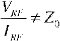
이 조건 하에서, 전압 Vi 및 Vv는 부등한 진폭을 갖고 서로 위상이 180도 다르지는 않다. 따라서, Vi 및 Vv의 합은 AC 성분을 갖는다. Vi 및 Vv가 서로 동위상이지만 부등한 진폭을 갖는 조건 또는 Vi 및 Vv가 서로 위상이 다르지만 동일한 진폭을 갖는 조건 하에서 Vi 및 Vv의 합은 AC 성분을 가질 수 있다는 것이 이해되어야한다. 대안적인 실시예에서, 부등한 진폭 조건 및/또는 위상이 다른 조건이 정합된 임피던스 조건을 나타내도록 Vi 및 Vv의 진폭 및 위상은 스케일링될 수 있다.Under these conditions, the voltages V i and V v have unequal amplitudes and are not 180 degrees out of phase with each other. Thus, the sum of V i and V v has an AC component. V i and V v are in phase with each other but have unequal amplitudes or under conditions where Vi and Vv have different phases but have the same amplitude It should be understood that the sum of V i and V v can have an AC component. In an alternative embodiment, the amplitude and phase of V i and V v can be scaled such that the unequal amplitude condition and / or the different phase conditions represent the matched impedance condition.
도 1a로 다시 돌아가면, 전압 감지 회로(104)의 AC 응답은 다음과 같이 설명될 수 있다.Turning back to FIG. 1A, the AC response of the
![]()
![]()
여기서, C v (jω)는 전압 감지 회로(104)의 결합 계수를 나타내고, 전류 감지 회로(102)의 AC 응답은 다음과 같이 설명될 수 있다.Here, C v (jω) represents the coupling coefficient of the voltage detection circuit (104), AC response of the
![]()
![]()
여기서, C i (jω)는 전류 감지 회로(102)의 결합 계수를 나타낸다. 마지막으로, 결합 회로(106)의 AC 응답은 다음과 같이 설명될 수 있다.Here, C i (jω) represents a coupling coefficient of the
![]()
![]()
여기서 m v (jω)는 Vv에 영향을 주는 것으로서 결합 회로(106)을 통한 신호 이득 및 위상 쉬프트를 나타내고, m i (jω)는 Vi에 영향을 주는 것으로서 결합 회로(106)을 통해 신호 이득 및 위상 쉬프트를 나타낸다.Where m v (jω) is as affecting V v represents the signal gain and phase shift through the
실시예에서, Z(jω)는 가장 높은 격리를 달성하기 위한 임피던스를 정의한다. 이상적인 커플러에서:In an embodiment, Z (jω) defines the impedance to achieve the highest isolation. From an ideal coupler:
![]()
![]()
![]()
![]()
여기서 Z 0 은 예를 들어, 일부 실시예에서, 50Ω인 기준 임피던스이다.Where Z 0 is, for example, a reference impedance of 50 OMEGA, in some embodiments.
C v (jω)=-C i (jω)일 때, 출력 포트(112)에서의 신호는 전송 포트(110)으로부터 입력 포트(108)로 전파되는 전자기력의 양을 나타내고, 동시에, 출력 포트(112)는 입력 포트(108)로부터 전송 포트(110)로 전파되는 전자기력으로부터 격리된다. 반면에, C v (jω)=C i (jω)일 때, 출력 포트(112)에서의 신호는 입력 포트(108)로부터 전송 포트(110)로 전파되는 전자기력의 양을 나타내고, 동시에, 출력 포트(112)는 전송 포트(110)로부터 입력 포트(108)로 전파되는 전자기력으로부터 격리된다. C v (jω) = - when C i (jω), the signal at the output port (112) represents the amount of electromagnetic force that is propagated to the
실시예에서, 전류 감지 회로(102) 및 전압 감지 회로(104)는 선형 패시브 네트워크를 사용하여 구현될 수 있다. 또한, 전류 감지 회로(102), 전압 감지 회로(104) 및 결합 회로(106)는 튜닝가능할 수 있어서, C v (jω), C i (jω), m v (jω) 및 m i (jω)는 전기적으로 조정가능하게 된다. 예를 들어, 전류 감지 회로(102), 전압 감지 회로(104) 및 결합 회로(106)는 조정가능한 AC 전달 함수를 제공하는 스위칭가능한 구성요소를 포함하는 패시브 네트워크를 포함할 수 있다.In an embodiment, the
도 2는 지향성 커플러(100)의 실시예의 구현을 도시하고, 이는 전류 감지 회로(102)가 입력 포트(108)와 전송 포트(110) 사이에서 결합되는 인덕터 LP로 나타낸 1차 권선과, 기준 노드와 결합 회로의 제 1 입력 사이에서 결합되는 인덕터 Ls로 나타낸 2차 권선을 갖는 자기 트랜스포머(120)를 사용하여 구현된다. 이 기준 노드는 일부 실시예에서 접지가 될 수 있거나 다른 실시예에서는 다른 기준 노드가 될 수 있다. 전압 감지 회로(104)는 전송 포트(110)와 결합 회로(106)의 제 2 입력 사이에서 결합되는 RC 네트워크를 포함한다. 대안적으로, 전압 감지 회로(104)는 입력 포트(108)와 결합 회로(106)의 제 2 입력 사이에서 결합될 수 있다. 자기 트랜스포머(120)의 동작은 전압 감지 회로(104)의 RC 네트워크와 함께 진행될 수 있고, 이는 본 명세서에서 전체가 참조로 통합되는 "트랜스포머 및 위상 쉬프트 네트워크를 위한 시스템 및 방법(System amd Method for a Transformer and a Phase-Shift Network)"라는 명칭으로 동시 진행중인(co-pending) 미국 특허 출원 번호 12/931,092번에서 설명되는 것이다. 일부 실시예에서, 결합 회로(106)는 전류 감지 회로(102)와 전압 감지 회로(104)로부터의 신호를 합하고 스케일링하는 두 임피던스를 포함한다. 결합 회로(106)에서의 두 임피던스는 예를 들어, 두 저항기로서 구현될 수 있다.2 shows an implementation of an embodiment of a
도 2의 실시예에서, 전압 Vv는 다음과 같이 표현될 수 있다.In the embodiment of Figure 2, the voltage V v can be expressed as follows.
![]()
![]()
여기서, R1은 전압 감지 회로(104)의 RC 네트워크의 저항이고 C1은 캐패시턴스이다. RC 네트워크의 컷오프 주파수는 커플러의 동작 주파수 범위를 훨씬 넘어가며, 즉,Where R 1 is the resistance of the RC network of the
![]()
![]()
수학식 6은 다음과 같이 근사화될 수 있다.Equation (6) can be approximated as follows.
![]()
![]()
따라서 수학식 1에 대해, 전압 감지 회로(104)의 전압 결합 계수 C v (jω)는 다음과 같이 표현될 수 있다.Thus, for equation (1), the voltage coupling coefficient C v (jω) of the
![]()
![]()
고 임피던스가 로딩되는 이상적인 트랜스포머에 대한 수학식을 사용하면(R2는 자기 트랜스포머의 2차 권선에서 보여지는 임피던스보다 더 높은 것으로 가정함), 전압 Vi는 다음과 같이 표현될 수 있다.Using the equation for an ideal transformer is a high-impedance loads (R2 is assumed to be higher than the impedance seen at the secondary winding of the magnetic transformer), the voltage V i may be represented as follows:
![]()
![]()
여기서 L p 및 L s 는 전류 감지 네트워크에서 트랜스포머의 1차 및 2차 권선의 자기 인덕턴스(self-inductances)이고, k는 1차 권선과 2차 권선 사이의 결합 계수이다. 실시예에서, 다양한 성분 및 파라미터, k, L p , L s , R 1 및 C 1 은 다음 조건을 만족시키도록 선택된다.Where L p and L s are the magnetic inductances of the primary and secondary windings of the transformer in the current sensing network and k is the coupling coefficient between the primary winding and the secondary winding. In an embodiment, various components and parameters, k, L p , L s , R 1 And C 1 is selected to satisfy the following condition.
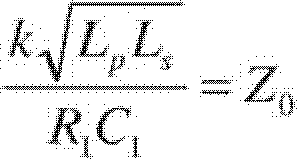
여기서 Z0은 기준 임피던스이다.Where Z 0 is the reference impedance.
수학식 11을 사용하여 수학식 10은 다음과 같이 수정될 수 있다.Using Equation (11), Equation (10) can be modified as follows.
![]()
![]()
따라서, 수학식 2에 대해, 전류 감지 회로(102)의 전류 결합 계수 C i (jω)는 다음과 같이 표현될 수 있다.Therefore, for equation (2), the current coupling coefficient C i (jω) of the
![]()
![]()
도 3은 도 2에서 도시된 실시예와 유사한 추가 실시예에 따른 지향성 커플러(150)를 도시하지만, 자기 트랜스포머(120)와 결합 회로(106) 사이에서 결합되는 방향 스위치(156)를 더 포함한다. 도시된 바와 같이, 방향 스위치(156)는, 전류 감지 회로(152)의 출력을 자기 트랜스포머(120)의 2차 권선의 각 단부로 선택적으로 스위칭하고, 기준 노드를 자기 트랜스포머(120)의 2차 권선의 다른 단부로 선택적으로 스위칭함으로써, 전류 감지 회로(152)의 출력의 극성을 반전시키도록 구성된다. 일부 실시예에서, 방향 스위치(156)는 스위칭 트랜지스터를 사용하여 구현될 수 있다. 또한, 전압 감지 회로(154)는 전송 포트(110)와 결합 회로의 제 2 입력 사이에서 결합되는 RC 네트워크를 포함한다. 대안적으로, 전압 감지 회로(154)는 입력 포트(108)와 결합 회로(106)의 제 2 입력 사이에서 결합될 수 있다. RC 네트워크는 전압 감지 회로(154)에 대한 튜닝가능한 전달 특성을 구현하는데 사용되는 캐패시터 C1, 튜닝가능한 저항기 R1 및 튜닝가능한 캐패시터 C2를 포함한다. 캐패시터 C1도 또한 튜닝가능할 수 있다.3 further illustrates a
지향성 커플러(150)의 전압 감지 회로는 다음과 같이 설명될 수 있다.The voltage sensing circuit of the
![]()
![]()
C2가 C1보다 작을 때, 수학식 14는 수학식 8에 의해 근사화될 수 있다. C2>>C1 일 때, 캐패시터 C2의 캐패시턴스에 따라, 0과 90도 사이의 값을 갖는 Vv와 VRF 사이에 위상 쉬프트가 존재한다. 캐패시터 C2의 캐패시턴스 및 저항기 R1의 저항을 조정함으로써, 전압 감지 네트워크의 전달 함수의 크기 및 위상이 튜닝될 수 있다. 추가적으로, 전압 감지 회로의 전달 함수의 크기 및 위상은 캐패시터 C1의 캐패시턴스를 조정함으로써 튜닝될 수 있다. 전압 감지 회로(154)의 토폴로지는 많은 가능한 실시예의 전압 감지 회로의 단지 일례일 뿐이라는 것이 이해되어야한다. 대안적인 실시예에서, 조정가능한 위상 쉬프트를 생성하는 다른 네트워크가 사용될 수 있다.When C 2 is less than C 1 , Equation (14) can be approximated by Equation (8). When C 2 >> C 1 , there is a phase shift between V v and V RF having a value between 0 and 90 degrees, depending on the capacitance of capacitor C 2 . By adjusting the capacitance of the capacitor C2 and the resistance of the resistor R1, the magnitude and phase of the transfer function of the voltage sensing network can be tuned. Additionally, the magnitude and phase of the transfer function of the voltage sensing circuit can be tuned by adjusting the capacitance of capacitor C 1 . It should be understood that the topology of the
전류 감지 회로(152)에서 방향 스위치(156)는 전압 Vi의 극성을 변경함으로써, 다음의 함수를 구현한다.In the
![]()
![]()
![]()
![]()
수학식 15 및 수학식 16에 의해 볼 수 있는 바와 같이, 선택 스위치는 전류 감지 회로(152)의 출력을 180도 반전시킨다. ![]()
![]()
![]()
![]()
도 4a 내지 도 4d는 결합 회로(106)를 구현하는데 사용될 수 있는 다양한 회로를 도시한다. 도 4a는 고정된 저항기 R2 및 R2를 포함하는 결합 회로(106)를 도시하고, 이는 오직 고정 비율만이 전류 감지 회로(102)와 전압 감지 회로(104)의 출력들 사이에서 필요한 실시예에서 사용될 수 있다. 도 4b는 저항기 R2 및/또는 저항기 R3가 튜닝가능한 결합 회로(160)를 도시한다. 도 4c에서는, 결합 회로(162)가 두 튜닝가능한 캐패시터 C3 및 C4를 사용하여 구현되고, 도 4d에서는, 결합회로(164)가 캐패시터 C4 및 C3 각각에 병렬로 결합되는 튜닝가능한 저항기 R2 및 R3를 사용하여 구현된다. 저항기 R2 및 R3와 캐패시터 C4 및 C3를 독립적으로 조정함으로써, m v (jω) 및 m i (jω)의 진폭 및 위상 모두가 조정될 수 있다.4A-4D illustrate various circuits that may be used to implement the
도 5a 및 도 5b는 실시예의 전압 감지 회로 및 결합 회로에서 튜닝가능한 컴포넌트를 구현하는데 사용될 수 있는 튜닝가능한 패시브 요소의 예시를 도시한다. 도 5a는 직렬로 결합되는 저항기 R21, R22 및 R23을 포함하는 실시예의 튜닝가능한 저항기를 도시한다. NMOS 저항기 M1, M2 및 M3는 저항기 R21, R22, R23을 선택적으로 단락시키는데 사용된다. 일례에서, R21, R22 및 R23의 저항의 합은 NMOS 트랜지스터 M1, M2 및 M3를 턴오프시킴으로써 선택될 수 있다. 다른 예시에서, R23의 저항이 트랜지스터 M2 및 M3를 턴온시키고 트랜지스터 M1을 턴오프시킴으로써 선택될 수 있다. 대안적인 실시예에서, 셋 보다 많거나 적은 스위칭 트랜지스터가 셋 보다 많거나 적은 저항기를 선택하는데 사용될 수 있다. 다른 실시예에서, 저항기는 조합 또는 병렬 저항기 및/또는 병렬 및 직렬 저항기 모두의 조합으로서 선택가능할 수 있다. 또한, 스위칭 트랜지스터 M1, M2 및 M3는 NMOS 트랜지스터 외에 다른 타입의 트랜지스터, 예를 들어, PMOS 트랜지스터, 양극성 접합 트랜지스터 및 다른 타입의 트랜지스터를 사용하여 구현될 수 있다.Figures 5A and 5B illustrate examples of tunable passive components that may be used to implement the tunable components in the voltage sensing circuit and coupling circuitry of the embodiment. 5A shows a tunable resistor of an embodiment including resistors R21, R22 and R23 coupled in series. The NMOS resistors M1, M2, and M3 are used to selectively short-circuit the resistors R21, R22, and R23. In one example, the sum of the resistances of R21, R22 and R23 can be selected by turning off the NMOS transistors M1, M2 and M3. In another example, the resistance of R23 can be selected by turning on transistors M2 and M3 and turning off transistor M1. In an alternative embodiment, more or less than three switching transistors may be used to select more or less than three resistors. In other embodiments, the resistors may be selectable as a combination or combination of parallel resistors and / or a combination of both parallel and series resistors. In addition, the switching transistors M1, M2, and M3 may be implemented using other types of transistors, such as PMOS transistors, bipolar junction transistors, and other types of transistors, in addition to NMOS transistors.
도 5b는 NMOS 트랜지스터 M4, M5 및 M6에 의해 선택되는 선택가능한 캐패시터 C31, C32 및 C33의 병렬 조합에 의해 구현되는 실시예의 튜닝가능한 캐패시터를 도시한다. 대안의 실시예에서, 셋 보다 많거나 적은 스위칭 트랜지스터가 셋 보다 많거나 적은 캐패시터를 선택하는데 사용될 수 있다. 다른 실시예에서, 캐패시터는 조합 또는 병렬 캐패시터 및/또는 병렬 및 직렬 캐패시터 모두의 조합으로서 선택가능할 수 있다. 또한, 스위칭 트랜지스터 M4, M5 및 M6는 NMOS 트랜지스터 외에 다른 타입의 트랜지스터, 예를 들어, PMOS 트랜지스터, 양극성 접합 트랜지스터 및 다른 타입의 트랜지스터를 사용하여 구현될 수 있다.FIG. 5B shows a tunable capacitor of an embodiment implemented by a parallel combination of selectable capacitors C31, C32, and C33 selected by NMOS transistors M4, M5, and M6. In alternative embodiments, more or less than three switching transistors may be used to select more or less than three capacitors. In other embodiments, the capacitors may be selectable as a combination or parallel capacitor and / or a combination of both parallel and series capacitors. In addition, the switching transistors M4, M5, and M6 may be implemented using transistors of other types than NMOS transistors, for example, PMOS transistors, bipolar junction transistors, and other types of transistors.
도 6은 디지털 인터페이스(204)를 통해 전류 감지 회로(152), 전압 감지 회로(104) 및 결합 회로(106)를 튜닝 및/또는 캘리브레이팅(calibrate)하는데 사용될 수 있는 제어기(202)를 더 포함한다. 도시된 바와 같이, 제어기(202)는 예를 들어, 상술된 바와 같은 이들의 블록 내에서 패시브 컴포넌트를 조정함으로써, 결합 회로(106) 및 전압 감지 회로(104) 내에서 설정을 제어하는데 사용될 수 있다. 제어기(202)는 방향 스위치를 제어하는 전류 감지 회로(152)에 더 결합 될 수 있다. 일부 실시예에서, 지향성 커플러(200)에서의 모든 요소는 하나 이상의 집적 회로 상에서 구현될 수 있다. 제어기(202)는 마이크로제어기, 마이크로프로세서, 상태 머신, 또는 다른 타입의 하드와이어드(hard-wired) 또는 프로그램가능한 로직을 사용하여 구현될 수 있다. 추가 실시예에서, 제어기(202)는 테스트 및 캘리브레이션 시퀀스에 대한 어느 정도의 제어를 제공하는 내장 자체 테스트 회로(built-in self-test circuitry)를 포함할 수 있다. 결정된 설정은 메모리(210)에 저장될 수 있고, EEPROM, 마스크 프로그램가능 ROM, 프로그램가능 퓨즈 또는 다른 타입의 메모리와 같은 비휘발성 메모리를 사용하여 구현될 수 있다. 테스팅 동안, 지향성 커플러(200)는 전송 포트(110)에 결합되는 입력을 갖는 테스터(212)의 제어 하에서 작동할 수 있다. 테스터(212)는 전류 감지 회로(152) 내에서의 방향 스위치 및 전압 감지 회로(104) 및 결합 회로(106) 내에서의 조정가능한 패시브 네트워크와 같은 컴포넌트의 상태를 제어할 수 있다.Figure 6 further illustrates a
도 7은 실시예의 지향성 커플러 캘리브레이션 방법(300)의 흐름도를 도시한다. 실시예에서, 입력 포트 및 전송 포트는 단계(302)에서 알려진 임피던스로 종단된다. 일부 실시예에서, 출력 포트는 또한 알려진 임피던스로 종단된다. 일부 실시예에서, 이들 임피던스는 Z0=50Ω와 같은 설정 특성 임피던스로 모두 종단된다. 대안적으로, 다른 임피던스가 사용될 수 있다. 예를 들어, 일부 실시예에서, 기생 보드 임피던스에 기인하여 발생할 수 있는 비이상적 시스템 부하를 캘리브레이팅하는 캘리브레이션 시퀀스를 가능하게 하기 위해, 입력 포트, 전송 포트 및/또는 출력 포트에 결합되는 임피던스는 의도적으로 부정합될 수 있다.FIG. 7 shows a flow diagram of a directional
다음으로, 단계(304)에서, RF 신호가 입력 포트 및/또는 전송 포트로 인가된다. 이 신호는, 예를 들어, RF 신호 발생기를 사용하여 인가될 수 있다. 단계(306)에서, 도 3에 도시된 방향 스위치(156)와 같은 방향 스위치는, 제 1 위치로 설정되어서 실시예의 전류 감지 회로의 출력이 제 1 극성의 신호를 제공한다. 다음으로, 단계(308)에서는, 지향성 커플러의 출력 포트에서 제 1 전력이 측정된다. 그 다음, 단계(310)에서는 전류 감지 회로의 출력의 극성을 반전시키기 위해 방향 스위치가 제 2 위치로 설정되고, 그 다음, 단계(312)에서는 출력 포트에서 제 2 전력이 측정된다. 그 다음, 단계(314)에서는 제 1 전력과 제 2 전력 사이의 차이 및/또는 비율을 계산함으로써 지향성이 계산된다.Next, at
그 다음, 단계(316)에서 계산된 지향성이 사전결정된 임계치와 비교된다. 일부 실시예에서, 이 사전결정된 임계치는, 예를 들어, 약 500MHz와 약 3GHz 사이의 주파수에 대해 약 20dB와 약 25dB 사이가 될 수 있다. 대안적으로, 이 범위 외의 다른 임계치 및 주파수는 특정 적용 및 이의 사양에 따라 사용될 수 있다. 지향성이 사전결정된 임계치보다 작다면, 단계(318)에서 전압 감지 회로 및/또는 결합기의 설정이 조정되고 단계(306) 내지 단계(316)가 반복된다. 당 기술 분야에서 알려진 최소 제곱 평균(a least-mean squares;LMS) 알고리즘 또는 다른 알고리즘과 같은 최적화 알고리즘을 사용하여 설정이 조정될 수 있다. 반면, 측정되고 계산된 지향성이 사전결정된 임계치 내에 존재하면, 단계(320)에서 전압 감지 회로 및/또는 전류 감지 회로의 설정이 비휘발성 메모리와 같은 메모리에 저장된다.The calculated directivity at
도 8a는 본 발명의 실시예에 따른 RF 시스템(400)을 도시한다. 시스템(400)은 실시예의 지향성 커플러(404) 및 튜닝가능한 정합 네트워크(406)를 통해 안테나(412)에 결합되는 RF 송수신기(402)를 포함한다. 지향성 커플러(404)의 출력 포트는 전력 검출기(408)에 결합되고, 이의 출력은 제어기(410)에 결합된다. 실시예에서, 제어기(410)는 전력 검출기(408)의 양자화된 출력에 따라 튜닝가능한 정합 네트워크(406)를 조정한다. 지향성 커플러(404)가 RF 송수신기(402)와 튜닝가능한 정합 네트워크(406)로의 입력 사이의 임피던스 부정합을 검출할 때, 일부 실시예에서, 임피던스에서 측정된 이의 부정합이 사전결정된 임계치 이하로 떨어질 때까지 제어기(410)는 튜닝가능한 정합 네트워크(406)를 조정한다. 일부 실시예에서, 제어기(410)는, 예를 들어, 프로세서, 마이크로제어기, 또는 전용 시스템 로직을 사용하여 구현될 수 있다. RF 시스템(400)은, 예를 들어, 셀룰러 전화기, 무선 로컬 영역 네트워크 송수신기 또는 다른 무선 주파수 시스템의 전달에서 구현될 수 있다. 일부 실시예에서, 시스템(420)에 대해 도 8에서 도시된 바와 같이, 튜닝가능한 정합 네트워크(406)는 RF 송수신기(402)와 지향성 커플러(404) 사이에서 결합된다. 8A illustrates an
도 8c는 본 발명의 다른 실시예에 따른 실시예의 레이더 시스템(450)을 도시한다. 시스템(450)은 실시예의 지향성 커플러(404)를 통해 안테나(412)에 결합되는 레이더 송수신기(452)를 포함한다. 지향성 커플러의 출력(604)은 전력 검출기(408)를 통해 제어기(410)에 결합된다. 실시예에서, 지향성 커플러(404)는 안테나(412)로부터 입사된 신호를 측정하여 반사된 레이더 펄스를 나타낼 수 있다. 시스템(450)은 예를 들어, 자동차용 또는 근접 레이더 시스템과 같은 레이더 시스템에서 사용될 수 있다. 지향성 커플러(404)는 예를 들어, 본원에서 개시된 실시예의 지향성 커플러를 사용하여 구현될 수 있다. 실시예의 반사 측정 회로를 활용할 수 있는 다른 예시 시스템은 평판 역에프 안테나(planar inverted F antenna;PIFA) 피드 포인트 튜너(feed-point tuner)에서의 전력 모니터링을 포함한다.8C illustrates a
도 8d는 실시예의 지향성 커플러(404)를 통해 안테나(412)에 결합되는 안테나 스위치(462)를 포함하는 실시예의 시스템(460)을 도시한다. 안테나 스위치(462)는 입력 S1 내지 SN 중 하나의 입력을 출력 노드 O1에 대해 선택 및 결합하도록 구성된다. 지향성 커플러(404)의 출력 포트는 전력 검출기(408)를 통해 제어기(410)에 결합된다. 시스템(460)은 예를 들어, 순방향으로 전송되고 반사된 전력을 측정하고 지향성 커플러(404) 내에서 극성 스위치의 위치를 선택함으로써 방향을 반전시키는데 사용될 수 있다. 지향성 커플러(404)의 출력은 포락선 트랙킹(envelope tracking) 및 안테나 튜닝을 수행하는데 더 사용될 수 있다.8D illustrates an embodiment of
도 8a 내지 도 8d에서 도시된 실시예는 많은 실시예의 시스템 중 단지 세 가지 예시가 실시예의 지향성 커플러를 사용하여 구현될 수 있다는 것이 이해되어야한다.It should be understood that the embodiment shown in Figures 8A-8D may be implemented using only three examples of systems of many embodiments using the directional coupler of the embodiment.
실시예에 따라, 회로는, 입력 포트에 결합되는 전류 입력 단자, 전송 포트에 결합되는 전류 출력 단자, 및 전류 입력 단자와 전류 출력 단자 사이에 흐르는 전류에 비례하는 전류 감지 신호를 제공하도록 구성된 전류 감지 출력 단자를 포함한 전류 감지 회로를 포함한다. 회로는 전송 포트에 결합되는 전압 입력 단자와, 전송 포트에서의 전압에 비례하는 전압 감지 신호를 제공하도록 구성된 전압 감지 출력 단자를 갖는 전압 감지 회로를 더 포함한다. 결합 회로는 전류 감지 출력 단자에 결합되는 제 1 입력과, 전압 감지 출력 단자에 결합되는 제 2 입력과, 출력 포트에 결합되는 결합된 출력 노드를 갖는다. 회로는 전압 감지 출력 단자와 전류 감지 출력 단자 사이의 진폭 차이 및 위상 차이에 기초하여 입력 포트와 전송 포트 사이에서 전파되는 전자기력의 양을 나타내도록 구성된다.According to an embodiment, the circuit includes a current input terminal coupled to the input port, a current output terminal coupled to the transmission port, and a current sense circuit configured to provide a current sense signal proportional to the current flowing between the current input terminal and the current output terminal. And a current sensing circuit including an output terminal. The circuit further includes a voltage sensing circuit having a voltage input terminal coupled to the transmission port and a voltage sensing output terminal configured to provide a voltage sensing signal proportional to the voltage at the transmission port. The coupling circuit has a first input coupled to the current sense output terminal, a second input coupled to the voltage sense output terminal, and a coupled output node coupled to the output port. Circuit is configured to indicate the amount of electromagnetic force propagating between the input port and the transmission port based on the amplitude difference and the phase difference between the voltage sense output terminal and the current sense output terminal.
실시예에서, 회로는 전류 입력 단자와 전류 출력 단자 사이에서 결합되는 제 1 권선과, 제 1 기준 노드와 전류 감지 출력 단자 사이에서 결합되는 제 2 권선을 갖는 자기 트랜스포머를 더 포함한다. 회로는 전류 감지 출력 단자와 제 2 권선 사이에서 결합되는 스위치를 더 포함한다. 스위치는 극성을 선택하도록 구성되고, 이 극성에 의해 전류 감지 출력 단자는 제 2 권선에 결합된다.In an embodiment, the circuit further comprises a magnetic transformer having a first winding coupled between the current input terminal and the current output terminal, and a second winding coupled between the first reference node and the current sense output terminal. The circuit further includes a switch coupled between the current sense output terminal and the second winding. The switch is configured to select the polarity, whereby the current sense output terminal is coupled to the second winding.
일부 실시예에서, 전압 감지 회로는 조정가능한 위상 및 진폭 응답을 갖는 조정가능한 네트워크를 포함한다. 조정가능한 네트워크는 전압 입력 단자와 전압 감지 출력 단자 사이에서 결합되는 직렬 캐패시터와, 전압 감지 출력 단자와 기준 노드 사이에서 결합되는 분로(shunt) 저항기를 포함하여서, 직렬 캐패시터 및 분로 저항기 중 적어도 하나가 조정가능하다. 다른 실시예에서, 조정가능한 네트워크는 전압 입력 단자와 전압 감지 출력 단자 사이에서 결합되는 직렬 캐패시터와, 전압 감지 출력 단자와 기준 노드 사이에서 결합되는 분로 저항기와, 전압 감지 출력 단자와 기준 노드 사이에서 결합되는 분로 캐패시터를 포함하여서, 직렬 캐패시터, 분로 저항기 및 분로 캐패시터 중 적어도 하나가 조정가능하다.In some embodiments, the voltage sensing circuit includes an adjustable network having an adjustable phase and amplitude response. The adjustable network includes a series capacitor coupled between a voltage input terminal and a voltage sense output terminal and a shunt resistor coupled between the voltage sense output terminal and a reference node such that at least one of the series capacitor and the shunt resistor It is possible. In another embodiment, the tunable network includes a series capacitor coupled between a voltage input terminal and a voltage sense output terminal, a shunt resistor coupled between the voltage sense output terminal and a reference node, At least one of a series capacitor, a shunt resistor, and a shunt capacitor is adjustable, including a shunt capacitor.
회로는 실질적으로 90도 위상 쉬프트를 생성하기 위해 조정가능한 네트워크를 캘리브레이팅하도록 구성되는 제어기를 더 포함한다. 일부 실시예에서, 회로는 회로의 지향성을 실질적으로 최대화하도록 조정가능한 네트워크를 캘리브레이팅하도록 구성되는 제어기를 포함한다. 실시예에서, 결합 회로는 추가의 조정가능한 패시브 네트워크를 포함하고, 제어기는 회로의 지향성을 실질적으로 최대화하기 위해 추가의 조정가능한 패시브 네트워크를 캘리브레이팅하도록 더 구성된다.The circuit further includes a controller configured to calibrate the adjustable network to produce a substantially 90 degree phase shift. In some embodiments, the circuit includes a controller configured to calibrate an adjustable network to substantially maximize the directivity of the circuit. In an embodiment, the combining circuit includes an additional tunable passive network, and the controller is further configured to calibrate an additional tunable passive network to substantially maximize the directivity of the circuit.
일부 실시예에서, 결합 회로는 전류 감지 출력 단자와 결합된 출력 노드 사이에서 결합되는 제 1 임피던스를 포함하고, 전압 감지 출력 단자와 결합된 출력 노드 사이에서 결합되는 제 2 임피던스를 포함한다. 제 1 임피던스는 제 1 저항기를 사용하여 구현될 수 있고, 제 2 임피던스는 제 2 저항기를 사용하여 구현될 수 있다. 대안적으로, 제 1 임피던스 및 제 2 임피던스는 제 1 캐패시터 및 제 2 캐패시터를 사용하여 구현될 수 있다. 일부 실시예에서, 제 1 임피던스는 제 1 조정가능한 임피던스를 포함할 수 있고, 제 2 임피던스는 제 2 조정가능한 임피던스를 포함할 수 있다. 예를 들어, 제 1 조정가능한 임피던스는 제 1 조정가능한 저항기를 사용하여 구현될 수 있고, 제 2 조정가능한 임피던스는 제 2 조정가능한 저항기를 사용하여 구현될 수 있다. 다른 실시예에서, 제 1 조정가능한 임피던스는 제 1 조정가능한 캐패시터를 사용하여 구현될 수 있고, 제 2 조정가능한 임피던스는 제 2 조정가능한 캐패시터를 사용하여 구현될 수 있다.In some embodiments, the coupling circuit includes a first impedance coupled between the current sense output terminal and the coupled output node, and a second impedance coupled between the voltage sense output terminal and the coupled output node. The first impedance may be implemented using a first resistor, and the second impedance may be implemented using a second resistor. Alternatively, the first impedance and the second impedance may be implemented using a first capacitor and a second capacitor. In some embodiments, the first impedance may comprise a first adjustable impedance, and the second impedance may comprise a second adjustable impedance. For example, the first adjustable impedance may be implemented using a first adjustable resistor, and the second adjustable impedance may be implemented using a second adjustable resistor. In another embodiment, the first adjustable impedance may be implemented using a first adjustable capacitor, and the second adjustable impedance may be implemented using a second adjustable capacitor.
추가의 실시예에 따라, 지향성 커플러는 입력 포트와 전송 포트 사이에서 결합되는 제 1 권선과, 선택가능한 극성 스위치를 통해 전류 감지 노드와 기준 노드에 결합되는 제 2 권선을 갖는 자기 트랜스포머를 포함한다. 지향성 커플러는 또는 전송 포트와 전압 감지 노드 사이에서 결합되는 조정가능한 패시브 네트워크를 포함하고, 결합 회로는 전류 감지 노드에 결합되는 제 1 입력과, 전압 감지 노드에 결합되는 제 2 입력과, 지향성 커플러의 출력 포트에 결합되는 출력을 갖는다.According to a further embodiment, the directional coupler includes a magnetic winding transformer having a first winding coupled between the input port and the transmission port, and a second winding coupled to the current sensing node and the reference node via a selectable polarity switch. The directional coupler includes an adjustable passive network coupled between the transmission port and the voltage sensing node, the coupling circuit including a first input coupled to the current sense node, a second input coupled to the voltage sense node, And an output coupled to the output port.
실시예에서, 입력 포트는 RF 신호 소스에 결합되도록 구성되고, 전송 포트는 제 1 RF 부하에 결합되도록 구성되고, 출력 포트는 제 2 RF 부하에 결합되도록 구성된다. 지향성 커플러는 조정가능한 패시브 네트워크를 조정함으로써 커플러의 지향성을 캘리브레이팅하도록 구성되는 제어기를 더 포함할 수 있다. 이 제어기는 (a) 선택가능한 극성 스위치를 제 1 위치로 설정하고, 출력 포트에서 제 1 전력을 측정하는 단계와, (b) 선택가능한 극성 스위치를 제 2 위치로 설정하고, 출력 포트에서 제 2 전력을 측정하는 단계와, (c) 제 1 전력과 제 2 전력 사이의 차이를 계산하는 단계와, (d) 차이가 사전결정된 임계치보다 작으면, 조정가능한 패시브 네트워크를 조정하는 단계에 의해 지향성을 캘리브레이팅하도록 구성될 수 있다. 일부 실시예에서, 제어기는, 차이가 사전결정된 임계치보다 작을 때, 단계(a), (b), (c) 및 (d)를 반복하도록 더 구성된다. 제어기는, 차이가 사전결정된 임계치보다 클 때, 조정가능한 패시브 네트워크에 대한 설정을 저장하도록 더 구성될 수 있다.In an embodiment, the input port is configured to couple to an RF signal source, the transmit port configured to couple to a first RF load, and the output port configured to couple to a second RF load. The directional coupler may further comprise a controller configured to calibrate the directivity of the coupler by adjusting the adjustable passive network. (A) setting a selectable polarity switch to a first position and measuring a first power at an output port, (b) setting a selectable polarity switch to a second position, and Measuring power; (c) calculating a difference between the first power and the second power; and (d) if the difference is less than the predetermined threshold, adjusting the adjustable passive network And may be configured to calibrate. In some embodiments, the controller is further configured to repeat steps (a), (b), (c), and (d) when the difference is less than the predetermined threshold. The controller may be further configured to store settings for the adjustable passive network when the difference is greater than a predetermined threshold.
실시예에서, 결합 회로는 조정가능한 결합 회로를 포함하고, 제어기는, 차이가 사전결정된 임계치보다 크면, 조정가능한 결합 회로를 조정하도록 더 구성된다.In an embodiment, the coupling circuit comprises an adjustable coupling circuit and the controller is further configured to adjust the adjustable coupling circuit if the difference is greater than a predetermined threshold.
추가 실시예에 따라, 지향성 커플러를 캘리브레이팅하는 방법은, 제 1 측정치를 형성하기 위해 지향성 커플러의 지향성을 측정하는 단계와, 상기 제 1 측정치가 사전결정된 임계치 미만일 때 지향성 커플러의 지향성을 증가시키기 위해 전압 감지 회로의 특성을 조정하는 단계와, 상기 제 1 측정치가 사전결정된 임계치를 초과할 때까지 상기 측정하는 단계와 상기 조정하는 단계를 반복하는 단계를 포함한다. 지향성 커플러 자체는 입력 포트와 전송 포트 사이에서 결합되는 전류 감지 회로와, 전송 포트와 전압 감지 출력 단자 사이에서 결합되는 전압 감지 회로와, 전압 감지 회로의 전압 감지 출력 단자 및 전류 감지 회로의 전류 감지 출력 단자에 결합되는 입력과, 지향성 커플러의 출력 포트에 결합되는 출력을 갖는 결합 회로를 포함한다.According to a further embodiment, a method of calibrating a directional coupler comprises the steps of measuring the directivity of a directional coupler to form a first measurement, and increasing the directivity of the directional coupler when the first measurement is below a predetermined threshold Adjusting the characteristics of the voltage sensing circuit and repeating the measuring and adjusting until the first measurement exceeds a predetermined threshold. The directional coupler itself includes a current sense circuit coupled between the input port and the transmit port, a voltage sense circuit coupled between the transmit port and the voltage sense output terminal, a voltage sense output terminal of the voltage sense circuit, and a current sense output An input coupled to the terminal, and an output coupled to the output port of the directional coupler.
실시예에서, 방법은 패시브 네트워크를 조정하는 단계를 포함하는 전압 감지 회로의 특성을 조정하는 단계를 더 포함한다. 일부 실시예에서, 결합 회로는 조정가능한 결합 회로를 포함하고, 방법은, 제 1 측정치가 사전결정된 임계치 미만일 때, 지향성 커플러의 지향성을 증가시키기 위해 조정가능한 결합 회로를 조정하는 단계를 더 포함한다. 조정가능한 결합 회로를 조정하는 단계는 전류 감지 출력 단자와 출력 포트 사이에서 결합되는 제 1 튜닝가능한 임피던스의 요소를 스위칭하는 단계와, 전압 감지 출력 단자와 출력 포트 사이에서 결합되는 제 2 튜닝가능한 임피던스의 요소를 스위칭하는 단계를 포함할 수 있다.In an embodiment, the method further comprises adjusting the characteristics of the voltage sensing circuit, comprising adjusting the passive network. In some embodiments, the combining circuit includes an adjustable combining circuit, and the method further comprises adjusting the adjustable combining circuit to increase the directivity of the directional coupler when the first measurement is below a predetermined threshold. Adjusting the adjustable coupling circuit comprises switching an element of a first tunable impedance coupled between the current sense output terminal and the output port and a second tunable impedance coupled between the voltage sense output terminal and the output port, And switching the element.
방법은 제 1 임피던스로 입력 포트를 종단시키는 단계와, 제 2 임피던스로 전송 포트를 종단시키는 단계를 더 포함할 수 있다. 다양한 실시예에서, 지향성을 측정하는 단계는 제 1 위치로 방향 스위치를 설정하는 단계를 포함하여서, 방향 스위치가 전류 감지 회로의 전류 감지 출력 단자의 극성을 선택하도록 구성된다. 지향성을 측정하는 단계는 입력 포트에서 제 1 RF 신호를 인가하는 단계와, 방향 스위치가 제 1 위치에 존재할 때 출력 포트에서 제 1 전력을 측정하는 단계와, 방향 스위치를 제 2 위치로 설정하는 단계와, 방향 스위치가 제 2 위치에 존재할 때 출력 포트에서 제 2 전력을 측정하는 단계와, 제 1 전력과 제 2 전력 사이의 차이를 계산하여 측정된 지향성을 형성하는 단계를 더 포함한다.The method may further include terminating the input port with a first impedance and terminating the transmission port with a second impedance. In various embodiments, measuring the directivity includes configuring the direction switch to the first position such that the direction switch is configured to select the polarity of the current sense output terminal of the current sense circuit. Measuring the directivity comprises applying a first RF signal at the input port, measuring a first power at the output port when the direction switch is in the first position, setting the direction switch to the second position Measuring a second power at the output port when the directional switch is in the second position, and calculating a difference between the first power and the second power to form the measured directivity.
전압 감지 회로의 특성을 조정하는 단계는 튜닝가능한 요소에 대한 설정을 전압 감지 회로에 적용하는 단계를 포함할 수 있다. 일부 실시예에서, 방법은 제 1 측정이 사전결정된 임계치를 초과한 이후에 비휘발성 메모리에 튜닝가능한 요소에 대한 설정을 저장하는 단계를 더 포함한다.Adjusting the characteristics of the voltage sensing circuit may include applying a setting for the tunable element to the voltage sensing circuit. In some embodiments, the method further comprises storing a setting for the tunable element in the non-volatile memory after the first measurement exceeds a predetermined threshold.
일부 실시예의 지향성 커플러의 장점은 단일의 결합되는 출력 포트만을 사용하여 순방향 및 역방향 모두에서 RF 신호의 전력을 모니터하는 기능을 포함한다. 다른 장점은 온 보드 기생(on-board parasitic) 임피던스에 기인한 변형 및 비이상적인 것뿐만 아니라, 컴포넌트 및 프로세스 변형을 보상하기 위해 지향성 커플러의 지향성을 캘리브레이팅하는 기능을 포함한다. 따라서, 실시예의 지향성 커플러는 표준 반도체 프로세스 및/또는 저렴한 컴포넌트를 사용하여 고지향성을 달성할 수 있다.The advantage of the directional coupler in some embodiments includes the ability to monitor the power of the RF signal in both the forward and reverse directions using only a single combined output port. Other advantages include the ability to calibrate the directivity of the directional coupler to compensate for component and process variations as well as variations and non-idealities due to on-board parasitic impedance. Thus, the directional coupler of the embodiment can achieve high directivity using standard semiconductor processes and / or inexpensive components.
본 발명은 도시된 실시예를 참조하여 설명된 반면, 본 상세한 설명은 제한하는 의미로 해석되도록 의도되지 않는다. 본 상세한 설명을 참조할 시에 본 발명의 다른 실시예뿐만 아니라, 도시된 실시예의 다양한 변형 및 조합이 당업자에게 명백할 것이다.While this invention has been described with reference to illustrative embodiments, this description is not intended to be construed in a limiting sense. Various modifications and combinations of the illustrated embodiments, as well as other embodiments of the invention, will be apparent to those skilled in the art in view of this specification.
Claims (31)
입력 포트(an input port)에 결합되는 전류 입력 단자, 전송 포트(a transmitted port)에 결합되는 전류 출력 단자, 및 상기 전류 입력 단자와 상기 전류 출력 단자 사이에 흐르는 전류에 비례하는 전류 감지 신호를 제공하도록 구성된 전류 감지 출력 단자를 포함한 전류 감지 회로와,
상기 전송 포트에 결합되는 전압 입력 단자 및 상기 전송 포트에서의 전압에 비례하는 전압 감지 신호를 제공하도록 구성된 전압 감지 출력 단자를 갖는 전압 감지 회로와,
상기 전류 감지 출력 단자에 결합되는 제 1 입력, 상기 전압 감지 출력 단자에 결합되는 제 2 입력, 및 출력 포트에 결합되는 결합된 출력 노드를 갖는 결합 회로(a combining circuit)를 포함하되,
상기 회로는 상기 전압 감지 출력 단자와 상기 전류 감지 출력 단자 사이의 진폭 차이 및 위상 차이에 기초하여 상기 입력 포트와 상기 전송 포트 사이에서 전파되는 전자기력(electromagnetic power)의 양을 나타내도록 구성되는
회로.
As a circuit,
A current input terminal coupled to an input port, a current output terminal coupled to a transmitted port, and a current sense signal proportional to a current flowing between the current input terminal and the current output terminal A current sense circuit including a current sense output terminal configured to < RTI ID = 0.0 >
A voltage sense circuit having a voltage input terminal coupled to the transmit port and a voltage sense output terminal configured to provide a voltage sense signal proportional to the voltage at the transmit port,
A combining circuit having a first input coupled to the current sense output terminal, a second input coupled to the voltage sense output terminal, and a coupled output node coupled to the output port,
The circuit is configured to indicate an amount of electromagnetic power propagating between the input port and the transmission port based on an amplitude difference and a phase difference between the voltage sense output terminal and the current sense output terminal
Circuit.
상기 전류 감지 회로는 상기 전류 입력 단자와 상기 전류 출력 단자 사이에서 결합되는 제 1 권선(winding)과, 제 1 기준 노드와 상기 전류 감지 출력 단자 사이에서 결합되는 제 2 권선을 갖는 자기 트랜스포머를 포함하는
회로.
The method according to claim 1,
Wherein the current sensing circuit includes a magnetic transformer having a first winding coupled between the current input terminal and the current output terminal and a second winding coupled between the first reference node and the current sense output terminal
Circuit.
상기 전류 감지 출력 단자와 상기 제 2 권선 사이에서 결합되는 스위치를 더 포함하는
회로.
3. The method of claim 2,
And a switch coupled between the current sense output terminal and the second winding
Circuit.
상기 스위치는 극성을 선택하도록 구성되고, 상기 극성에 의해 상기 전류 감지 출력 단자는 상기 제 2 권선에 결합되는
회로.
The method of claim 3,
Wherein the switch is configured to select a polarity such that the current sense output terminal is coupled to the second winding
Circuit.
상기 전압 감지 회로는 조정가능한 위상 및 진폭 응답을 갖는 조정가능한 네트워크를 포함하는
회로.
The method according to claim 1,
Wherein the voltage sensing circuit comprises an adjustable network having an adjustable phase and amplitude response
Circuit.
상기 조정가능한 네트워크는,
상기 전압 입력 단자와 상기 전압 감지 출력 단자 사이에서 결합되는 직렬 캐패시터와,
상기 전압 감지 출력 단자와 기준 노드 사이에서 결합되는 분로 저항기(a shunt resistor)를 포함하고, 상기 직렬 캐패시터 및 상기 분로 저항기 중 적어도 하나가 조정가능한
회로.
6. The method of claim 5,
The adjustable network comprising:
A series capacitor coupled between the voltage input terminal and the voltage sense output terminal,
And a shunt resistor coupled between the voltage sense output terminal and a reference node, wherein at least one of the series capacitor and the shunt resistor is adjustable
Circuit.
상기 조정가능한 네트워크는,
상기 전압 입력 단자와 상기 전압 감지 출력 단자 사이에서 결합되는 직렬 캐패시터와,
상기 전압 감지 출력 단자와 기준 노드 사이에서 결합되는 분로 저항기와,
상기 전압 감지 출력 단자와 기준 노드 사이에서 결합되는 분로 캐패시터를 포함하고, 상기 직렬 캐패시터, 상기 분로 저항기 및 상기 분로 캐패시터 중 적어도 하나가 조정가능한
회로.
6. The method of claim 5,
The adjustable network comprising:
A series capacitor coupled between the voltage input terminal and the voltage sense output terminal,
A shunt resistor coupled between the voltage sensing output terminal and a reference node,
And a shunt capacitor coupled between the voltage sense output terminal and a reference node, wherein at least one of the series capacitor, the shunt resistor, and the shunt capacitor is adjustable
Circuit.
실질적으로 90도 위상 쉬프트를 생성하기 위해 상기 조정가능한 네트워크를 캘리브레이팅(calibrate)하도록 구성되는 제어기를 더 포함하는
회로.
6. The method of claim 5,
Further comprising a controller configured to calibrate the adjustable network to produce a substantially 90 degree phase shift
Circuit.
상기 회로의 지향성(directivity)을 실질적으로 최대화하도록 상기 조정가능한 네트워크를 캘리브레이팅하도록 구성되는 제어기를 더 포함하는
회로.
6. The method of claim 5,
Further comprising a controller configured to calibrate the adjustable network to substantially maximize the directivity of the circuitry
Circuit.
상기 결합 회로는 추가의 조정가능한 패시브 네트워크를 포함하고, 상기 제어기는 상기 회로의 지향성을 실질적으로 최대화하기 위해 상기 추가의 조정가능한 패시브 네트워크를 캘리브레이팅하도록 더 구성되는
회로.
10. The method of claim 9,
Wherein the coupling circuit comprises an additional tunable passive network and the controller is further configured to calibrate the further tunable passive network to substantially maximize the directivity of the circuit
Circuit.
상기 결합 회로는,
상기 전류 감지 출력 단자와 상기 결합된 출력 노드 사이에서 결합되는 제 1 임피던스와,
상기 전압 감지 출력 단자와 상기 결합된 출력 노드 사이에서 결합되는 제 2 임피던스를 포함하는
회로.
The method according to claim 1,
Wherein the coupling circuit comprises:
A first impedance coupled between the current sense output terminal and the coupled output node,
And a second impedance coupled between the voltage sense output terminal and the coupled output node
Circuit.
상기 제 1 임피던스는 제 1 저항이고,
상기 제 2 임피던스는 제 2 저항인
회로.
12. The method of claim 11,
The first impedance is a first resistance,
The second impedance is a second resistance
Circuit.
상기 제 1 임피던스는 제 1 캐패시터이고,
상기 제 2 임피던스는 제 2 캐패시터인
회로.
12. The method of claim 11,
The first impedance is a first capacitor,
The second impedance is a second capacitor
Circuit.
상기 제 1 임피던스는 제 1 조정가능한 임피던스를 포함하고,
상기 제 2 임피던스는 제 2 조정가능한 임피던스를 포함하는
회로.
12. The method of claim 11,
Wherein the first impedance comprises a first adjustable impedance,
Wherein the second impedance comprises a second adjustable impedance
Circuit.
상기 제 1 조정가능한 임피던스는 제 1 조정가능한 저항이고,
상기 제 2 조정가능한 임피던스는 제 2 조정가능한 저항인
회로.
15. The method of claim 14,
Wherein the first adjustable impedance is a first adjustable resistance,
Wherein the second adjustable impedance is a second adjustable resistance
Circuit.
상기 제 1 조정가능한 임피던스는 제 1 조정가능한 캐패시터이고,
상기 제 2 조정가능한 임피던스는 제 2 조정가능한 캐패시터인
회로.
15. The method of claim 14,
Wherein the first adjustable impedance is a first adjustable capacitor,
The second adjustable impedance is a second adjustable capacitor
Circuit.
상기 전송 포트와 전압 감지 노드 사이에서 결합되는 조정가능한 패시브 네트워크와,
상기 전류 감지 노드에 결합되는 제 1 입력, 상기 전압 감지 노드에 결합되는 제 2 입력, 및 지향성 커플러(a directional coupler)의 출력 포트에 결합되는 출력을 갖는 결합 회로를 포함하는
지향성 커플러.
A magnetic transformer having a first winding coupled between the input port and the transfer port, a second winding coupled to the current sense node and the reference node via a selectable polarity switch,
An adjustable passive network coupled between the transmit port and the voltage sensing node,
A coupling circuit having a first input coupled to the current sense node, a second input coupled to the voltage sensing node, and an output coupled to an output port of a directional coupler
Directional coupler.
상기 입력 포트는 RF 신호 소스에 결합되도록 구성되고,
상기 전송 포트는 제 1 RF 부하에 결합되도록 구성되고,
상기 출력 포트는 제 2 RF 부하에 결합되도록 구성되는
지향성 커플러.
18. The method of claim 17,
The input port being configured to couple to an RF signal source,
Wherein the transmit port is configured to be coupled to a first RF load,
The output port is configured to be coupled to a second RF load
Directional coupler.
상기 조정가능한 패시브 네트워크를 조정함으로써 상기 지향성 커플러의 지향성을 캘리브레이팅하도록 구성되는 제어기를 더 포함하는
지향성 커플러.
18. The method of claim 17,
And a controller configured to calibrate the directivity of the directional coupler by adjusting the adjustable passive network
Directional coupler.
상기 제어기는,
(a) 상기 선택가능한 극성 스위치를 제 1 위치로 설정하고 출력 포트에서 제 1 전력을 측정하는 단계와,
(b) 상기 선택가능한 극성 스위치를 제 2 위치로 설정하고 상기 출력 포트에서 제 2 전력을 측정하는 단계와,
(c) 상기 제 1 전력과 상기 제 2 전력 사이의 차이를 계산하는 단계와,
(d) 상기 차이가 사전결정된 임계치보다 작으면, 상기 조정가능한 패시브 네트워크를 조정하는 단계에 의해 상기 지향성을 캘리브레이팅하도록 구성되는
지향성 커플러.
20. The method of claim 19,
The controller comprising:
(a) setting the selectable polarity switch to a first position and measuring a first power at an output port,
(b) setting the selectable polarity switch to a second position and measuring a second power at the output port,
(c) calculating a difference between the first power and the second power;
(d) if the difference is less than a predetermined threshold, calibrating the directivity by adjusting the adjustable passive network
Directional coupler.
상기 제어기는,
상기 차이가 상기 사전결정된 임계치보다 클 때, 상기 조정가능한 패시브 네트워크에 대한 설정을 저장하도록 더 구성되는
지향성 커플러.
21. The method of claim 20,
The controller comprising:
And to store settings for the adjustable passive network when the difference is greater than the predetermined threshold
Directional coupler.
상기 제어기는,
상기 차이가 상기 사전결정된 임계치보다 작을 때, 단계 (a), (b), (c) 및 (d)를 반복하도록 더 구성되는
지향성 커플러.
21. The method of claim 20,
The controller comprising:
And to repeat steps (a), (b), (c) and (d) when the difference is less than the predetermined threshold
Directional coupler.
상기 결합 회로는 조정가능한 결합 회로를 포함하고,
상기 제어기는, 상기 차이가 상기 사전결정된 임계치보다 크면, 조정가능한 결합 회로를 조정하도록 더 구성되는
지향성 커플러.
21. The method of claim 20,
The coupling circuit comprising an adjustable coupling circuit,
The controller is further configured to adjust the adjustable coupling circuit if the difference is greater than the predetermined threshold
Directional coupler.
상기 방법은,
제 1 측정치를 형성하기 위해 상기 지향성 커플러의 지향성을 측정하는 단계와,
상기 제 1 측정치가 사전결정된 임계치 미만일 때 상기 지향성 커플러의 지향성을 증가시키기 위해 상기 전압 감지 회로의 특성을 조정하는 단계와,
상기 제 1 측정치가 상기 사전결정된 임계치를 초과할 때까지 상기 측정하는 단계와 상기 조정하는 단계를 반복하는 단계를 포함하는
지향성 커플러 캘리브레이팅 방법.
A method for calibrating a directional coupler, the directional coupler comprising: a current sense circuit coupled between an input port and a transmit port; a voltage sense circuit coupled between the transmit port and a voltage sense output terminal; A coupling circuit having an input coupled to a voltage sense output terminal and a current sense output terminal of the current sense circuit, and an output coupled to an output port of the directional coupler,
The method comprises:
Measuring the directivity of the directional coupler to form a first measurement;
Adjusting the characteristics of the voltage sensing circuit to increase the directivity of the directional coupler when the first measurement is below a predetermined threshold;
Repeating said measuring step and said adjusting step until said first measurement value exceeds said predetermined threshold value
Directional coupler calibration method.
상기 전압 감지 회로의 특성을 조정하는 단계는 패시브 네트워크를 조정하는 단계를 포함하는
지향성 커플러 캘리브레이팅 방법.25. The method of claim 24,
Wherein adjusting the characteristics of the voltage sensing circuit comprises adjusting a passive network
Directional coupler calibration method.
상기 결합 회로는 조정가능한 결합 회로를 포함하고,
상기 방법은,
상기 제 1 측정치가 상기 사전결정된 임계치 미만일 때, 상기 지향성 커플러의 지향성을 증가시키기 위해 상기 조정가능한 결합 회로를 조정하는 단계를 더 포함하는
지향성 커플러 캘리브레이팅 방법.
26. The method of claim 25,
The coupling circuit comprising an adjustable coupling circuit,
The method comprises:
Further comprising adjusting the adjustable coupling circuit to increase the directivity of the directional coupler when the first measure is below the predetermined threshold
Directional coupler calibration method.
상기 조정가능한 결합 회로를 조정하는 단계는 상기 전류 감지 출력 단자와 상기 출력 포트 사이에서 결합되는 제 1 튜닝가능한 임피던스의 요소들을 스위칭하는 단계와, 상기 전압 감지 출력 단자와 상기 출력 포트 사이에서 결합되는 제 2 튜닝가능한 임피던스의 요소들을 스위칭하는 단계를 포함하는
지향성 커플러 캘리브레이팅 방법.
27. The method of claim 26,
Wherein adjusting the adjustable coupling circuit comprises: switching elements of a first tunable impedance coupled between the current sense output terminal and the output port; and coupling the voltage sense output terminal to the output port, Lt; RTI ID = 0.0 > 2 < / RTI >
Directional coupler calibration method.
제 1 임피던스로 상기 입력 포트를 종단(terminating)시키는 단계와,
제 2 임피던스로 상기 전송 포트를 종단시키는 단계를 더 포함하는
지향성 커플러 캘리브레이팅 방법.
25. The method of claim 24,
Terminating the input port with a first impedance;
Further comprising terminating the transmission port with a second impedance
Directional coupler calibration method.
상기 지향성을 측정하는 단계는,
제 1 위치로 방향 스위치를 설정하는 단계―상기 방향 스위치는 상기 전류 감지 회로의 전류 감지 출력 단자의 극성을 선택하도록 구성됨―와,
상기 입력 포트에서 제 1 RF 신호를 인가하는 단계와,
상기 방향 스위치가 상기 제 1 위치에 존재할 때 상기 출력 포트에서 제 1 전력을 측정하는 단계와,
상기 방향 스위치를 제 2 위치로 설정하는 단계와,
상기 방향 스위치가 상기 제 2 위치에 존재할 때 상기 출력 포트에서 제 2 전력을 측정하는 단계와,
상기 제 1 전력과 상기 제 2 전력 사이의 차이를 계산하여 측정된 지향성을 생성하는 단계를 포함하는
지향성 커플러 캘리브레이팅 방법.
29. The method of claim 28,
Wherein the step of measuring the directivity comprises:
Setting a direction switch to a first position, the direction switch being configured to select a polarity of a current sense output terminal of the current sense circuit;
Applying a first RF signal at the input port,
Measuring a first power at the output port when the direction switch is in the first position,
Setting the direction switch to a second position,
Measuring a second power at the output port when the direction switch is in the second position,
Calculating a difference between the first power and the second power to produce a measured directivity
Directional coupler calibration method.
상기 전압 감지 회로의 특성을 조정하는 단계는 튜닝가능한 요소에 대한 설정을 상기 전압 감지 회로에 적용하는 단계를 포함하는
지향성 커플러 캘리브레이팅 방법.
25. The method of claim 24,
Wherein adjusting the characteristics of the voltage sensing circuit comprises applying a setting for the tunable element to the voltage sensing circuit
Directional coupler calibration method.
상기 제 1 측정치가 상기 사전결정된 임계치를 초과한 이후에 비휘발성 메모리에 상기 튜닝가능한 요소에 대한 설정을 저장하는 단계를 더 포함하는
지향성 커플러 캘리브레이팅 방법.31. The method of claim 30,
Further comprising storing the setting for the tunable element in a non-volatile memory after the first measurement exceeds the predetermined threshold
Directional coupler calibration method.
Applications Claiming Priority (2)
| Application Number | Priority Date | Filing Date | Title |
|---|---|---|---|
| US14/155,130 US9608305B2 (en) | 2014-01-14 | 2014-01-14 | System and method for a directional coupler with a combining circuit |
| US14/155,130 | 2014-01-14 |
Publications (2)
| Publication Number | Publication Date |
|---|---|
| KR20150084679A true KR20150084679A (en) | 2015-07-22 |
| KR101645119B1 KR101645119B1 (en) | 2016-08-02 |
Family
ID=53485127
Family Applications (1)
| Application Number | Title | Priority Date | Filing Date |
|---|---|---|---|
| KR1020150006427A Active KR101645119B1 (en) | 2014-01-14 | 2015-01-13 | System and method for a directional coupler |
Country Status (4)
| Country | Link |
|---|---|
| US (1) | US9608305B2 (en) |
| KR (1) | KR101645119B1 (en) |
| CN (1) | CN104779429B (en) |
| DE (1) | DE102015100385B4 (en) |
Families Citing this family (28)
| Publication number | Priority date | Publication date | Assignee | Title |
|---|---|---|---|---|
| US9755670B2 (en) | 2014-05-29 | 2017-09-05 | Skyworks Solutions, Inc. | Adaptive load for coupler in broadband multimode multiband front end module |
| DE112015002750B4 (en) | 2014-06-12 | 2025-11-20 | Skyworks Solutions Inc. | Devices and methods relating to directional couplers |
| US9553617B2 (en) | 2014-07-24 | 2017-01-24 | Skyworks Solutions, Inc. | Apparatus and methods for reconfigurable directional couplers in an RF transceiver with controllable capacitive coupling |
| US9866260B2 (en) | 2014-09-12 | 2018-01-09 | Infineon Technologies Ag | System and method for a directional coupler module |
| US9685687B2 (en) * | 2014-09-15 | 2017-06-20 | Infineon Technologies Ag | System and method for a directional coupler |
| US9812757B2 (en) | 2014-12-10 | 2017-11-07 | Skyworks Solutions, Inc. | RF coupler having coupled line with adjustable length |
| US9947985B2 (en) | 2015-07-20 | 2018-04-17 | Infineon Technologies Ag | System and method for a directional coupler |
| US9893750B2 (en) * | 2015-08-17 | 2018-02-13 | Qorvo Us, Inc. | Tunable transmit cancellation in acoustic receiver filters |
| CN108292793B (en) | 2015-09-10 | 2021-03-09 | 天工方案公司 | Electromagnetic coupler for multi-frequency power detection |
| DE102015225592A1 (en) * | 2015-12-17 | 2017-06-22 | Robert Bosch Gmbh | Apparatus for processing or generating a signal and method for determining an adaptation |
| US10009052B2 (en) * | 2016-02-01 | 2018-06-26 | Qorvo Us, Inc. | UL CA TX-TX tunable cross-isolation method |
| US9954564B2 (en) | 2016-02-05 | 2018-04-24 | Skyworks Solutions, Inc. | Electromagnetic couplers with multi-band filtering |
| WO2017151321A1 (en) | 2016-02-29 | 2017-09-08 | Skyworks Solutions, Inc. | Integrated filter and directional coupler assemblies |
| CN109155361B (en) | 2016-03-30 | 2022-11-08 | 天工方案公司 | Tunable active silicon for coupler linearity improvement and reconfiguration |
| WO2017189824A1 (en) | 2016-04-29 | 2017-11-02 | Skyworks Solutions, Inc. | Compensated electromagnetic coupler |
| CN109314299B (en) | 2016-04-29 | 2021-09-21 | 天工方案公司 | Tunable electromagnetic coupler and module and device using same |
| WO2017196652A2 (en) | 2016-05-09 | 2017-11-16 | Skyworks Solutions, Inc. | Self-adjusting electromagnetic coupler with automatic frequency detection |
| US10164681B2 (en) | 2016-06-06 | 2018-12-25 | Skyworks Solutions, Inc. | Isolating noise sources and coupling fields in RF chips |
| CN109565292B (en) | 2016-06-22 | 2021-02-05 | 天工方案公司 | Electromagnetic coupler device for multi-frequency power detection and apparatus containing the same |
| US10148294B2 (en) | 2016-12-06 | 2018-12-04 | Qorvo Us, Inc. | Multi-band radio frequency front-end circuit |
| US10742189B2 (en) | 2017-06-06 | 2020-08-11 | Skyworks Solutions, Inc. | Switched multi-coupler apparatus and modules and devices using same |
| CN110632533B (en) * | 2019-08-08 | 2022-09-27 | 苏州博维仪器科技有限公司 | Power detection system of RF (radio frequency) power supply |
| CN111398870B (en) * | 2020-04-02 | 2022-03-11 | 中国南方电网有限责任公司 | Relay protection transformer polarity testing method based on power system topology identification |
| US11953531B2 (en) * | 2020-05-20 | 2024-04-09 | Cirrus Logic Inc. | Sense resistor and method for forming same |
| WO2022104743A1 (en) * | 2020-11-20 | 2022-05-27 | 华为技术有限公司 | Directivity calibration apparatus and method for bidirectional coupler |
| CN114976550A (en) | 2021-02-23 | 2022-08-30 | 天工方案公司 | Intelligent bidirectional coupler with switchable inductor |
| GB2609719B (en) | 2021-06-02 | 2025-03-12 | Skyworks Solutions Inc | Directional coupler with multiple arrangements of termination |
| EP4174516A1 (en) * | 2021-10-26 | 2023-05-03 | Veoneer Sweden AB | Radar transceiver calibration |
Citations (4)
| Publication number | Priority date | Publication date | Assignee | Title |
|---|---|---|---|---|
| KR20030010586A (en) * | 2000-03-02 | 2003-02-05 | 사르노프 코포레이션 | Method and apparatus for measuring true transmitted power using a broadband dual directional coupler |
| KR20060057658A (en) * | 2004-11-23 | 2006-05-26 | 엘지전자 주식회사 | Transmission power control circuit of mobile phone |
| US20120001693A1 (en) * | 2007-07-11 | 2012-01-05 | Rahul Magoon | Power amplifier amplitude modulator system and method |
| KR20120028176A (en) * | 2010-09-14 | 2012-03-22 | 엘지이노텍 주식회사 | Impedance tracer in adaptive tuning antenna circuit |
Family Cites Families (14)
| Publication number | Priority date | Publication date | Assignee | Title |
|---|---|---|---|---|
| US4493112A (en) * | 1981-11-19 | 1985-01-08 | Rockwell International Corporation | Antenna tuner discriminator |
| US4434397A (en) * | 1981-12-24 | 1984-02-28 | General Electric Company | Remote load current sensor |
| US4795886A (en) * | 1986-12-19 | 1989-01-03 | Metcal, Inc. | Temperature control in which the control parameter is the degree of imperfection in the impedance matching |
| DE3704181A1 (en) | 1987-02-11 | 1988-08-25 | Licentia Gmbh | Directional coupler arrangement |
| US6201452B1 (en) * | 1998-12-10 | 2001-03-13 | Ericsson Inc. | Systems and methods for converting a stream of complex numbers into a modulated radio power signal |
| JP3618055B2 (en) * | 1999-02-05 | 2005-02-09 | 富士通株式会社 | Portable mobile terminal and transmitter |
| US6917245B2 (en) | 2000-09-12 | 2005-07-12 | Silicon Laboratories, Inc. | Absolute power detector |
| EP1792192A1 (en) * | 2004-09-14 | 2007-06-06 | Koninklijke Philips Electronics N.V. | Circuit for detecting the impedance of a load |
| US7546089B2 (en) * | 2004-12-23 | 2009-06-09 | Triquint Semiconductor, Inc. | Switchable directional coupler for use with RF devices |
| DE202007010239U1 (en) * | 2007-07-24 | 2007-09-20 | Rosenberger Hochfrequenztechnik Gmbh & Co. Kg | loop- |
| WO2011004419A1 (en) * | 2009-07-06 | 2011-01-13 | 株式会社 東芝 | Directional coupler |
| US8195857B2 (en) * | 2009-12-18 | 2012-06-05 | Infineon Technologies Ag | Coupling devices, system comprising a coupling device and method for use in a system comprising a coupling device |
| CN102243304A (en) * | 2010-05-14 | 2011-11-16 | 中国科学院空间科学与应用研究中心 | Foundation-based atmosphere profile microwave detector |
| US9535140B2 (en) | 2013-06-28 | 2017-01-03 | Infineon Technologies Ag | System and method for a transformer and a phase-shift network |
-
2014
- 2014-01-14 US US14/155,130 patent/US9608305B2/en active Active
-
2015
- 2015-01-13 KR KR1020150006427A patent/KR101645119B1/en active Active
- 2015-01-13 DE DE102015100385.6A patent/DE102015100385B4/en active Active
- 2015-01-13 CN CN201510016350.1A patent/CN104779429B/en active Active
Patent Citations (4)
| Publication number | Priority date | Publication date | Assignee | Title |
|---|---|---|---|---|
| KR20030010586A (en) * | 2000-03-02 | 2003-02-05 | 사르노프 코포레이션 | Method and apparatus for measuring true transmitted power using a broadband dual directional coupler |
| KR20060057658A (en) * | 2004-11-23 | 2006-05-26 | 엘지전자 주식회사 | Transmission power control circuit of mobile phone |
| US20120001693A1 (en) * | 2007-07-11 | 2012-01-05 | Rahul Magoon | Power amplifier amplitude modulator system and method |
| KR20120028176A (en) * | 2010-09-14 | 2012-03-22 | 엘지이노텍 주식회사 | Impedance tracer in adaptive tuning antenna circuit |
Also Published As
| Publication number | Publication date |
|---|---|
| DE102015100385B4 (en) | 2023-07-20 |
| US20150200437A1 (en) | 2015-07-16 |
| CN104779429A (en) | 2015-07-15 |
| DE102015100385A1 (en) | 2015-07-16 |
| KR101645119B1 (en) | 2016-08-02 |
| US9608305B2 (en) | 2017-03-28 |
| CN104779429B (en) | 2018-05-04 |
Similar Documents
| Publication | Publication Date | Title |
|---|---|---|
| KR101645119B1 (en) | System and method for a directional coupler | |
| KR101855836B1 (en) | System and method for a directional coupler | |
| US9685687B2 (en) | System and method for a directional coupler | |
| KR101432397B1 (en) | Power and impedance measurement circuits for a wireless communication device | |
| KR101770471B1 (en) | System and method for a directional coupler module | |
| KR101658286B1 (en) | System and method for a radio frequency coupler | |
| CN104871459B (en) | wireless communication device, base station, RF transmission circuit and related method | |
| US8674782B2 (en) | RF impedance detection using two point voltage sampling | |
| US9154084B2 (en) | Low-noise receiver with complex RF attenuator | |
| WO2013123072A1 (en) | Programmable directional coupler | |
| CN104251939B (en) | For transformer and the system and method for phase-shift network | |
| US20190296709A1 (en) | Impedance matching circuitry | |
| US20150293159A1 (en) | Multi-band impedance detector | |
| US10826151B2 (en) | Directional coupler circuit and power amplifying device with phase compensation function | |
| KR101575520B1 (en) | System and method for a phase detector | |
| KR101694548B1 (en) | Impedance tracer in adaptive tuning antenna circuit | |
| US9651582B2 (en) | Integrated circuit device for impedance measurement | |
| Tavakol et al. | An impedance sensor for MEMS adaptive antenna matching | |
| HK40057166B (en) | Tuning of a magnetic antenna |
Legal Events
| Date | Code | Title | Description |
|---|---|---|---|
| A201 | Request for examination | ||
| PA0109 | Patent application |
Patent event code: PA01091R01D Comment text: Patent Application Patent event date: 20150113 |
|
| PA0201 | Request for examination | ||
| PG1501 | Laying open of application | ||
| E902 | Notification of reason for refusal | ||
| PE0902 | Notice of grounds for rejection |
Comment text: Notification of reason for refusal Patent event date: 20151021 Patent event code: PE09021S01D |
|
| E701 | Decision to grant or registration of patent right | ||
| PE0701 | Decision of registration |
Patent event code: PE07011S01D Comment text: Decision to Grant Registration Patent event date: 20160427 |
|
| GRNT | Written decision to grant | ||
| PR0701 | Registration of establishment |
Comment text: Registration of Establishment Patent event date: 20160727 Patent event code: PR07011E01D |
|
| PR1002 | Payment of registration fee |
Payment date: 20160727 End annual number: 3 Start annual number: 1 |
|
| PG1601 | Publication of registration | ||
| PR1001 | Payment of annual fee |
Payment date: 20190719 Start annual number: 4 End annual number: 4 |
|
| PR1001 | Payment of annual fee |
Payment date: 20200717 Start annual number: 5 End annual number: 5 |
|
| PR1001 | Payment of annual fee |
Payment date: 20210716 Start annual number: 6 End annual number: 6 |
|
| PR1001 | Payment of annual fee |
Payment date: 20220715 Start annual number: 7 End annual number: 7 |