KR102341451B1 - Robot system, method and non-trnasitory computer readable storage medium for instrument insertion compensation - Google Patents
Robot system, method and non-trnasitory computer readable storage medium for instrument insertion compensation Download PDFInfo
- Publication number
- KR102341451B1 KR102341451B1 KR1020207002273A KR20207002273A KR102341451B1 KR 102341451 B1 KR102341451 B1 KR 102341451B1 KR 1020207002273 A KR1020207002273 A KR 1020207002273A KR 20207002273 A KR20207002273 A KR 20207002273A KR 102341451 B1 KR102341451 B1 KR 102341451B1
- Authority
- KR
- South Korea
- Prior art keywords
- distal end
- instrument
- shaft
- change
- data
- Prior art date
- Legal status (The legal status is an assumption and is not a legal conclusion. Google has not performed a legal analysis and makes no representation as to the accuracy of the status listed.)
- Active
Links
Images


Classifications
-
- A—HUMAN NECESSITIES
- A61—MEDICAL OR VETERINARY SCIENCE; HYGIENE
- A61B—DIAGNOSIS; SURGERY; IDENTIFICATION
- A61B34/00—Computer-aided surgery; Manipulators or robots specially adapted for use in surgery
- A61B34/70—Manipulators specially adapted for use in surgery
- A61B34/71—Manipulators operated by drive cable mechanisms
-
- A—HUMAN NECESSITIES
- A61—MEDICAL OR VETERINARY SCIENCE; HYGIENE
- A61B—DIAGNOSIS; SURGERY; IDENTIFICATION
- A61B1/00—Instruments for performing medical examinations of the interior of cavities or tubes of the body by visual or photographical inspection, e.g. endoscopes; Illuminating arrangements therefor
- A61B1/00147—Holding or positioning arrangements
- A61B1/00149—Holding or positioning arrangements using articulated arms
-
- A—HUMAN NECESSITIES
- A61—MEDICAL OR VETERINARY SCIENCE; HYGIENE
- A61B—DIAGNOSIS; SURGERY; IDENTIFICATION
- A61B1/00—Instruments for performing medical examinations of the interior of cavities or tubes of the body by visual or photographical inspection, e.g. endoscopes; Illuminating arrangements therefor
- A61B1/00147—Holding or positioning arrangements
- A61B1/0016—Holding or positioning arrangements using motor drive units
-
- A—HUMAN NECESSITIES
- A61—MEDICAL OR VETERINARY SCIENCE; HYGIENE
- A61B—DIAGNOSIS; SURGERY; IDENTIFICATION
- A61B1/00—Instruments for performing medical examinations of the interior of cavities or tubes of the body by visual or photographical inspection, e.g. endoscopes; Illuminating arrangements therefor
- A61B1/005—Flexible endoscopes
- A61B1/0051—Flexible endoscopes with controlled bending of insertion part
-
- A—HUMAN NECESSITIES
- A61—MEDICAL OR VETERINARY SCIENCE; HYGIENE
- A61B—DIAGNOSIS; SURGERY; IDENTIFICATION
- A61B1/00—Instruments for performing medical examinations of the interior of cavities or tubes of the body by visual or photographical inspection, e.g. endoscopes; Illuminating arrangements therefor
- A61B1/012—Instruments for performing medical examinations of the interior of cavities or tubes of the body by visual or photographical inspection, e.g. endoscopes; Illuminating arrangements therefor characterised by internal passages or accessories therefor
- A61B1/018—Instruments for performing medical examinations of the interior of cavities or tubes of the body by visual or photographical inspection, e.g. endoscopes; Illuminating arrangements therefor characterised by internal passages or accessories therefor for receiving instruments
-
- A—HUMAN NECESSITIES
- A61—MEDICAL OR VETERINARY SCIENCE; HYGIENE
- A61B—DIAGNOSIS; SURGERY; IDENTIFICATION
- A61B1/00—Instruments for performing medical examinations of the interior of cavities or tubes of the body by visual or photographical inspection, e.g. endoscopes; Illuminating arrangements therefor
- A61B1/267—Instruments for performing medical examinations of the interior of cavities or tubes of the body by visual or photographical inspection, e.g. endoscopes; Illuminating arrangements therefor for the respiratory tract, e.g. laryngoscopes, bronchoscopes
- A61B1/2676—Bronchoscopes
-
- A—HUMAN NECESSITIES
- A61—MEDICAL OR VETERINARY SCIENCE; HYGIENE
- A61B—DIAGNOSIS; SURGERY; IDENTIFICATION
- A61B34/00—Computer-aided surgery; Manipulators or robots specially adapted for use in surgery
- A61B34/20—Surgical navigation systems; Devices for tracking or guiding surgical instruments, e.g. for frameless stereotaxis
-
- A—HUMAN NECESSITIES
- A61—MEDICAL OR VETERINARY SCIENCE; HYGIENE
- A61B—DIAGNOSIS; SURGERY; IDENTIFICATION
- A61B34/00—Computer-aided surgery; Manipulators or robots specially adapted for use in surgery
- A61B34/30—Surgical robots
-
- A—HUMAN NECESSITIES
- A61—MEDICAL OR VETERINARY SCIENCE; HYGIENE
- A61B—DIAGNOSIS; SURGERY; IDENTIFICATION
- A61B5/00—Measuring for diagnostic purposes; Identification of persons
- A61B5/06—Devices, other than using radiation, for detecting or locating foreign bodies ; Determining position of diagnostic devices within or on the body of the patient
- A61B5/061—Determining position of a probe within the body employing means separate from the probe, e.g. sensing internal probe position employing impedance electrodes on the surface of the body
- A61B5/062—Determining position of a probe within the body employing means separate from the probe, e.g. sensing internal probe position employing impedance electrodes on the surface of the body using magnetic field
-
- A—HUMAN NECESSITIES
- A61—MEDICAL OR VETERINARY SCIENCE; HYGIENE
- A61B—DIAGNOSIS; SURGERY; IDENTIFICATION
- A61B5/00—Measuring for diagnostic purposes; Identification of persons
- A61B5/06—Devices, other than using radiation, for detecting or locating foreign bodies ; Determining position of diagnostic devices within or on the body of the patient
- A61B5/065—Determining position of the probe employing exclusively positioning means located on or in the probe, e.g. using position sensors arranged on the probe
- A61B5/067—Determining position of the probe employing exclusively positioning means located on or in the probe, e.g. using position sensors arranged on the probe using accelerometers or gyroscopes
-
- A—HUMAN NECESSITIES
- A61—MEDICAL OR VETERINARY SCIENCE; HYGIENE
- A61B—DIAGNOSIS; SURGERY; IDENTIFICATION
- A61B90/00—Instruments, implements or accessories specially adapted for surgery or diagnosis and not covered by any of the groups A61B1/00 - A61B50/00, e.g. for luxation treatment or for protecting wound edges
- A61B90/36—Image-producing devices or illumination devices not otherwise provided for
- A61B90/361—Image-producing devices, e.g. surgical cameras
-
- A—HUMAN NECESSITIES
- A61—MEDICAL OR VETERINARY SCIENCE; HYGIENE
- A61B—DIAGNOSIS; SURGERY; IDENTIFICATION
- A61B90/00—Instruments, implements or accessories specially adapted for surgery or diagnosis and not covered by any of the groups A61B1/00 - A61B50/00, e.g. for luxation treatment or for protecting wound edges
- A61B90/60—Supports for surgeons, e.g. chairs or hand supports
-
- A—HUMAN NECESSITIES
- A61—MEDICAL OR VETERINARY SCIENCE; HYGIENE
- A61B—DIAGNOSIS; SURGERY; IDENTIFICATION
- A61B90/00—Instruments, implements or accessories specially adapted for surgery or diagnosis and not covered by any of the groups A61B1/00 - A61B50/00, e.g. for luxation treatment or for protecting wound edges
- A61B90/90—Identification means for patients or instruments, e.g. tags
-
- A—HUMAN NECESSITIES
- A61—MEDICAL OR VETERINARY SCIENCE; HYGIENE
- A61B—DIAGNOSIS; SURGERY; IDENTIFICATION
- A61B17/00—Surgical instruments, devices or methods
- A61B2017/00743—Type of operation; Specification of treatment sites
- A61B2017/00809—Lung operations
-
- A—HUMAN NECESSITIES
- A61—MEDICAL OR VETERINARY SCIENCE; HYGIENE
- A61B—DIAGNOSIS; SURGERY; IDENTIFICATION
- A61B34/00—Computer-aided surgery; Manipulators or robots specially adapted for use in surgery
- A61B34/20—Surgical navigation systems; Devices for tracking or guiding surgical instruments, e.g. for frameless stereotaxis
- A61B2034/2046—Tracking techniques
- A61B2034/2048—Tracking techniques using an accelerometer or inertia sensor
-
- A—HUMAN NECESSITIES
- A61—MEDICAL OR VETERINARY SCIENCE; HYGIENE
- A61B—DIAGNOSIS; SURGERY; IDENTIFICATION
- A61B34/00—Computer-aided surgery; Manipulators or robots specially adapted for use in surgery
- A61B34/20—Surgical navigation systems; Devices for tracking or guiding surgical instruments, e.g. for frameless stereotaxis
- A61B2034/2046—Tracking techniques
- A61B2034/2051—Electromagnetic tracking systems
-
- A—HUMAN NECESSITIES
- A61—MEDICAL OR VETERINARY SCIENCE; HYGIENE
- A61B—DIAGNOSIS; SURGERY; IDENTIFICATION
- A61B34/00—Computer-aided surgery; Manipulators or robots specially adapted for use in surgery
- A61B34/20—Surgical navigation systems; Devices for tracking or guiding surgical instruments, e.g. for frameless stereotaxis
- A61B2034/2046—Tracking techniques
- A61B2034/2059—Mechanical position encoders
-
- A—HUMAN NECESSITIES
- A61—MEDICAL OR VETERINARY SCIENCE; HYGIENE
- A61B—DIAGNOSIS; SURGERY; IDENTIFICATION
- A61B34/00—Computer-aided surgery; Manipulators or robots specially adapted for use in surgery
- A61B34/20—Surgical navigation systems; Devices for tracking or guiding surgical instruments, e.g. for frameless stereotaxis
- A61B2034/2046—Tracking techniques
- A61B2034/2065—Tracking using image or pattern recognition
-
- A—HUMAN NECESSITIES
- A61—MEDICAL OR VETERINARY SCIENCE; HYGIENE
- A61B—DIAGNOSIS; SURGERY; IDENTIFICATION
- A61B90/00—Instruments, implements or accessories specially adapted for surgery or diagnosis and not covered by any of the groups A61B1/00 - A61B50/00, e.g. for luxation treatment or for protecting wound edges
- A61B90/30—Devices for illuminating a surgical field, the devices having an interrelation with other surgical devices or with a surgical procedure
- A61B2090/309—Devices for illuminating a surgical field, the devices having an interrelation with other surgical devices or with a surgical procedure using white LEDs
-
- A—HUMAN NECESSITIES
- A61—MEDICAL OR VETERINARY SCIENCE; HYGIENE
- A61B—DIAGNOSIS; SURGERY; IDENTIFICATION
- A61B90/00—Instruments, implements or accessories specially adapted for surgery or diagnosis and not covered by any of the groups A61B1/00 - A61B50/00, e.g. for luxation treatment or for protecting wound edges
- A61B90/36—Image-producing devices or illumination devices not otherwise provided for
- A61B90/361—Image-producing devices, e.g. surgical cameras
- A61B2090/3614—Image-producing devices, e.g. surgical cameras using optical fibre
-
- A—HUMAN NECESSITIES
- A61—MEDICAL OR VETERINARY SCIENCE; HYGIENE
- A61B—DIAGNOSIS; SURGERY; IDENTIFICATION
- A61B90/00—Instruments, implements or accessories specially adapted for surgery or diagnosis and not covered by any of the groups A61B1/00 - A61B50/00, e.g. for luxation treatment or for protecting wound edges
- A61B90/36—Image-producing devices or illumination devices not otherwise provided for
- A61B90/37—Surgical systems with images on a monitor during operation
- A61B2090/376—Surgical systems with images on a monitor during operation using X-rays, e.g. fluoroscopy
-
- A—HUMAN NECESSITIES
- A61—MEDICAL OR VETERINARY SCIENCE; HYGIENE
- A61B—DIAGNOSIS; SURGERY; IDENTIFICATION
- A61B90/00—Instruments, implements or accessories specially adapted for surgery or diagnosis and not covered by any of the groups A61B1/00 - A61B50/00, e.g. for luxation treatment or for protecting wound edges
- A61B90/39—Markers, e.g. radio-opaque or breast lesions markers
- A61B2090/3966—Radiopaque markers visible in an X-ray image
-
- A—HUMAN NECESSITIES
- A61—MEDICAL OR VETERINARY SCIENCE; HYGIENE
- A61B—DIAGNOSIS; SURGERY; IDENTIFICATION
- A61B34/00—Computer-aided surgery; Manipulators or robots specially adapted for use in surgery
- A61B34/25—User interfaces for surgical systems
-
- A—HUMAN NECESSITIES
- A61—MEDICAL OR VETERINARY SCIENCE; HYGIENE
- A61B—DIAGNOSIS; SURGERY; IDENTIFICATION
- A61B5/00—Measuring for diagnostic purposes; Identification of persons
- A61B5/08—Measuring devices for evaluating the respiratory organs
- A61B5/0803—Recording apparatus specially adapted therefor
-
- A—HUMAN NECESSITIES
- A61—MEDICAL OR VETERINARY SCIENCE; HYGIENE
- A61B—DIAGNOSIS; SURGERY; IDENTIFICATION
- A61B90/00—Instruments, implements or accessories specially adapted for surgery or diagnosis and not covered by any of the groups A61B1/00 - A61B50/00, e.g. for luxation treatment or for protecting wound edges
- A61B90/39—Markers, e.g. radio-opaque or breast lesions markers
-
- A—HUMAN NECESSITIES
- A61—MEDICAL OR VETERINARY SCIENCE; HYGIENE
- A61B—DIAGNOSIS; SURGERY; IDENTIFICATION
- A61B90/00—Instruments, implements or accessories specially adapted for surgery or diagnosis and not covered by any of the groups A61B1/00 - A61B50/00, e.g. for luxation treatment or for protecting wound edges
- A61B90/90—Identification means for patients or instruments, e.g. tags
- A61B90/94—Identification means for patients or instruments, e.g. tags coded with symbols, e.g. text
- A61B90/96—Identification means for patients or instruments, e.g. tags coded with symbols, e.g. text using barcodes
-
- A—HUMAN NECESSITIES
- A61—MEDICAL OR VETERINARY SCIENCE; HYGIENE
- A61B—DIAGNOSIS; SURGERY; IDENTIFICATION
- A61B90/00—Instruments, implements or accessories specially adapted for surgery or diagnosis and not covered by any of the groups A61B1/00 - A61B50/00, e.g. for luxation treatment or for protecting wound edges
- A61B90/90—Identification means for patients or instruments, e.g. tags
- A61B90/98—Identification means for patients or instruments, e.g. tags using electromagnetic means, e.g. transponders
Landscapes
- Health & Medical Sciences (AREA)
- Life Sciences & Earth Sciences (AREA)
- Surgery (AREA)
- Engineering & Computer Science (AREA)
- Veterinary Medicine (AREA)
- Animal Behavior & Ethology (AREA)
- Public Health (AREA)
- Biomedical Technology (AREA)
- Heart & Thoracic Surgery (AREA)
- Medical Informatics (AREA)
- Molecular Biology (AREA)
- General Health & Medical Sciences (AREA)
- Nuclear Medicine, Radiotherapy & Molecular Imaging (AREA)
- Pathology (AREA)
- Physics & Mathematics (AREA)
- Biophysics (AREA)
- Optics & Photonics (AREA)
- Radiology & Medical Imaging (AREA)
- Robotics (AREA)
- Oral & Maxillofacial Surgery (AREA)
- Human Computer Interaction (AREA)
- Pulmonology (AREA)
- Otolaryngology (AREA)
- Physiology (AREA)
- Dentistry (AREA)
- Endoscopes (AREA)
- Manipulator (AREA)
- Surgical Instruments (AREA)
Abstract
본 명세서에는 외과 시스템에서 다른 기기의 작업 채널 내로의 기기의 삽입을 보상하기 위한 시스템 및 기술이 개시된다. 일 실시예에 따르면, 보상 방법은: 가요성 기기의 작업 채널 내로의 삽입 가능 기기의 삽입을 검출하는 단계; 적어도 하나의 센서로부터의 데이터 신호에 기초하여, 초기 위치로부터의 가요성 기기의 원위 부분의 위치 변화를 검출하는 단계: 검출된 위치 변화에 기초하여 제어 신호를 생성하는 단계; 및 원위 부분을 초기 위치로 복귀시키기 위해 제어 신호에 기초하여 풀 와이어의 인장을 조정하는 단계를 포함한다.Disclosed herein are systems and techniques for compensating for insertion of an instrument into a working channel of another instrument in a surgical system. According to one embodiment, a compensation method comprises: detecting insertion of an insertable device into a working channel of a flexible device; detecting, based on the data signal from the at least one sensor, a change in position of the distal portion of the flexible device from the initial position: generating a control signal based on the detected change in position; and adjusting the tension of the pull wire based on the control signal to return the distal portion to the initial position.
Description
관련 출원에 대한 상호 참조CROSS-REFERENCE TO RELATED APPLICATIONS
본 출원은 2017년 6월 28일자로 제출된 미국 가특허 출원 제62,526,008호의 권익을 주장하며, 상기 특허 문헌은 그 전체가 본 명세서에 참조로 통합되어 있다.This application claims the interests of US Provisional Patent Application No. 62,526,008 filed on June 28, 2017, the entirety of which is incorporated herein by reference.
기술 분야technical field
본 발명은 일반적으로 의료 장치에 관한 것으로, 보다 구체적으로는 로봇 보조 수술에 관한 것이다.TECHNICAL FIELD The present invention relates generally to medical devices, and more particularly to robot-assisted surgery.
내시경 검사(예를 들면, 기관지 내시경 검사)와 같은 의료 시술에는 진단 및/또는 치료 목적으로 환자의 루멘(lumen)(예를 들면, 기도)의 내부에 액세스하여 시각화하는 것이 포함될 수 있다. 시술 중에, 예를 들면 내시경과 같은 가요성 관형 툴(flexible tubular tool)이 환자의 신체 내로 삽입될 수 있으며, 기기가 내시경을 통해 진단 및/또는 치료를 위해 식별된 조직 부위로 통과될 수 있다. 예를 들어, 내시경은 조직 부위로의 경로를 제공하는 내부 루멘(예를 들면, "작업 채널")을 가질 수 있으며, 다양한 툴/기기가 내부 루멘을 통해 조직 부위로 삽입될 수 있다. 시술 중에 내시경 및/또는 툴/기기의 삽입 및/또는 조종을 제어하는 데 로봇 시스템이 사용될 수 있으며, 시술 중에 내시경 및/또는 툴/기기의 포지셔닝을 제어하도록 구성된 매니퓰레이터 어셈블리(manipulator assembly)를 포함하는 적어도 하나의 로봇 아암을 포함할 수 있다.
(선행기술문헌)
(특허문헌 1) 국제 출원 공개공보 제2017/048194호Medical procedures, such as endoscopy (eg, bronchoscopy), may include accessing and visualizing the interior of a patient's lumen (eg, airway) for diagnostic and/or therapeutic purposes. During the procedure, a flexible tubular tool, such as, for example, an endoscope, may be inserted into the patient's body, and the instrument may be passed through the endoscope to an identified tissue site for diagnosis and/or treatment. For example, an endoscope may have an internal lumen (eg, a “working channel”) that provides a pathway to a tissue site through which various tools/instruments may be inserted into the tissue site. A robotic system may be used to control insertion and/or manipulation of an endoscope and/or tool/instrument during a procedure, comprising a manipulator assembly configured to control positioning of the endoscope and/or tool/instrument during a procedure at least one robot arm.
(Prior art literature)
(Patent Document 1) International Publication No. 2017/048194
본 발명의 시스템, 기술, 및 장치는 각각 몇 가지 혁신적인 양태를 가지며, 이들 중 어느 것 하나도 본 명세서에 기술된 바람직한 속성들을 단독으로 감당하지는 않는다.The systems, techniques, and devices of the present invention each have several innovative aspects, none of which alone is tolerant of the desirable attributes described herein.
의료 시술에는 조작자로부터 원격에 위치된 가요성 기기의 조종이 포함될 수 있다. 예를 들어, 원하는 조직 부위에 대응하는 환자 내의 타겟 위치로의 루멘 또는 루멘 네트워크 내에서 이미징, 생검 샘플링, 치료제의 전달, 및/또는 수술이 수행될 수 있으며, 원하는 조직 부위에 액세스하기 위해 가요성 기기의 작업 채널을 통해 다른 기기를 삽입한다.A medical procedure may include manipulation of a flexible instrument located remotely from an operator. For example, imaging, biopsy sampling, delivery of therapeutic agents, and/or surgery may be performed within a lumen or network of lumens to a target location in a patient corresponding to a desired tissue site, and flexible to access the desired tissue site. Insert another device through the working channel of the device.
외과용의 기존의 가요성 기기와 연관된 하나의 과제는, 가요성 기기의 작업 채널을 통해 삽입 가능 기기를 전진시키거나 연장시키는 것은 그 원위 단부가 타겟 위치로부터 이동되도록 가요성 기기의 디플렉션을 야기할 수 있다는 것이다. 이러한 디플렉션의 결과로, 가요성 기기의 원위 단부는 조직 부위에 대해 오정렬될 수 있다.One challenge associated with existing flexible instruments for surgical use is that advancing or extending an insertable instrument through a working channel of the flexible instrument causes deflection of the flexible instrument such that its distal end is moved from the target position. that you can do it As a result of this deflection, the distal end of the flexible instrument may be misaligned relative to the tissue site.
따라서, 본 발명의 특정 양태들은 다른 기기가 가요성 기기의 작업 채널을 통해 삽입될 때 가요성 기기의 디플렉션을 방지, 최소화, 및/또는 보상하는 것을 용이하게 하는 시스템 및 기술에 관한 것이다. 본 발명의 다른 양태는 디플렉션의 근원에 관계없이 이러한 가요성 기기의 디플렉션을 방지, 최소화, 및/또는 보상하는 것을 용이하게 하는 시스템 및 기술에 관한 것이다.Accordingly, certain aspects of the present invention relate to systems and techniques that facilitate preventing, minimizing, and/or compensating for deflection of a flexible device when another device is inserted through a working channel of the flexible device. Another aspect of the present invention relates to systems and techniques that facilitate preventing, minimizing, and/or compensating for deflection in such flexible devices regardless of the source of the deflection.
따라서, 본 발명의 제1 양태는 로봇 시스템에 관한 것이다. 로봇 시스템은 제1 기기를 포함하고, 제1 기기는 근위 부분 및 원위 부분을 갖는 샤프트를 포함한다. 원위 부분은 관절 운동 가능 영역 및 원위 단부를 포함한다. 샤프트는 이를 통해 연장되는 작업 채널을 포함한다. 로봇 시스템은 또한 적어도 하나의 풀 와이어(pull wire) 및 샤프트의 원위 단부의 위치를 검출하도록 구성된 적어도 하나의 센서를 포함한다. 로봇 시스템은 또한 실행 가능 명령들이 저장된 적어도 하나의 컴퓨터 가독 메모리 및 적어도 하나의 컴퓨터 가독 메모리와 통신하는 하나 이상의 프로세서를 포함한다. 하나 이상의 프로세서는 명령들을 실행하도록 구성된다. 명령들은 시스템이 적어도 하나의 센서로부터의 데이터 신호에 기초하여, 샤프트의 작업 채널 내로의 제2 기기의 삽입에 응답하여 샤프트의 원위 단부의 위치 변화를 검출하게 한다. 명령들은 또한 시스템이 검출된 위치 변화에 기초하여 적어도 하나의 제어 신호를 생성하게 한다. 로봇 시스템은 또한 샤프트의 근위 부분에서 적어도 하나의 풀 와이어에 연결된 구동 메커니즘을 포함한다. 구동 메커니즘은 적어도 하나의 제어 신호에 기초하여 적어도 하나의 풀 와이어의 인장을 조정하도록 구성된다. 조정된 인장은 샤프트의 원위 단부를 위치 변화가 발생하기 전의 초기 위치 쪽으로 복귀시키는 것을 용이하게 한다.Accordingly, a first aspect of the present invention relates to a robotic system. The robotic system includes a first instrument, the first instrument comprising a shaft having a proximal portion and a distal portion. The distal portion includes an articulated region and a distal end. The shaft includes a working channel extending therethrough. The robotic system also includes at least one pull wire and at least one sensor configured to detect a position of the distal end of the shaft. The robotic system also includes at least one computer readable memory having executable instructions stored thereon and one or more processors in communication with the at least one computer readable memory. The one or more processors are configured to execute the instructions. The instructions cause the system to detect, based on a data signal from the at least one sensor, a change in position of the distal end of the shaft in response to insertion of the second instrument into the working channel of the shaft. The instructions also cause the system to generate at least one control signal based on the detected change in position. The robotic system also includes a drive mechanism coupled to at least one pull wire in the proximal portion of the shaft. The drive mechanism is configured to adjust tension of the at least one pull wire based on the at least one control signal. The adjusted tensioning facilitates returning the distal end of the shaft to its initial position before the change in position occurred.
일 실시예에 따른 로봇 시스템은 다음의 특징들 중 하나 이상을 임의의 조합으로 포함할 수 있다: 구동 메커니즘은 로봇 아암의 엔드 이펙터(end effector)에 연결되고, 로봇 아암 및 구동 메커니즘은 환자의 루멘 네트워크(luminal network)를 통해 치료 부위로 샤프트의 원위 부분을 내비게이션시키도록 구성되며; 전자기(electromagnetic: EM) 필드 발생기를 구비하고, 적어도 하나의 센서는 샤프트의 원위 단부에 제1 세트의 하나 이상의 EM 센서를 포함하고, 하나 이상의 프로세서는 시스템이 제1 세트의 EM 센서로부터의 데이터에 기초하여 EM 필드 내의 제1 세트의 EM 센서의 제1 위치를 계산하고 계산된 제1 위치에 기초하여 샤프트의 원위 단부의 위치 변화를 검출하도록 명령들을 실행하도록 구성되며; 제2 기기는 원위 단부에 제2 세트의 하나 이상의 EM 센서를 더 포함하고, 하나 이상의 프로세서는 시스템이 제2 세트의 EM 센서로부터의 데이터에 기초하여 EM 필드 내의 제2 세트의 EM 센서의 제2 위치를 계산하고 계산된 제2 위치에 또한 기초하여 적어도 하나의 제어 신호를 생성하도록 명령들을 실행하도록 구성되며; 적어도 하나의 센서는 샤프트의 원위 단부에 하나 이상의 관성 센서의 세트를 포함하고, 하나 이상의 프로세서는 시스템이 하나 이상의 관성 센서의 세트로부터의 데이터에 기초하여 하나 이상의 관성 센서의 세트의 제1 위치를 계산하고, 계산된 제1 위치에 또한 기초하여 적어도 하나의 제어 신호를 생성하도록, 명령들을 실행하도록 구성되며; 적어도 하나의 센서는 하나 이상의 스트레인 게이지(strain gauges)의 세트를 포함하고, 하나 이상의 프로세서는 시스템이 하나 이상의 스트레인 게이지의 세트로부터의 데이터에 기초하여 샤프트의 원위 단부의 제1 위치를 계산하고, 계산된 제1 위치에 또한 기초하여 적어도 하나의 제어 신호를 생성하도록, 명령들을 실행하도록 구성되며; 구동 메커니즘은 하나 이상의 스트레인 게이지의 세트를 포함하고; 제1 기기는 리더(leader)를 포함하고, 적어도 하나의 센서는 리더의 원위 단부에 하나 이상의 카메라의 세트를 포함하며; 적어도 하나의 제어 신호의 명령들은 샤프트의 원위 단부가 적어도 하나의 센서로부터의 데이터 신호에 의해 측정됨에 따라 초기 위치로 복귀될 때까지, 구동 메커니즘이 풀 와이어들 중 하나 이상의 장력을 증가시키도록 하는 커맨드(commands)를 포함하고; 하나 이상의 프로세서는 시스템을 제어하기 위한 사용자 인터페이스를 포함하는 워크스테이션의 일부이며; 적어도 하나의 호흡 센서를 구비하고, 하나 이상의 프로세서는 시스템이 적어도 하나의 호흡 센서로부터의 데이터에 기초하여, 적어도 하나의 센서로부터 데이터 신호의 획득 중에 환자의 호흡 패턴을 결정하고, 작업 채널 내로의 제2 기기의 삽입에 의해 야기되는 샤프트의 원위 단부의 위치 변화와 환자의 호흡 패턴에 의해 야기되는 샤프트의 원위 단부의 위치 변화를 구별하도록, 명령들을 실행하도록 또한 구성되며; 하나 이상의 프로세서는 시스템이 제2 기기 상의 식별자를 검출하고, 검출된 식별자에 또한 기초하여 적어도 하나의 제어 신호를 생성하도록, 명령들을 실행하도록 구성되고; 및/또는, 하나 이상의 프로세서는 시스템이 제2 기기의 무선 주파수 식별 태그를 판독하는 것에 기초하여 식별자를 검출하도록 명령들을 실행하도록 구성된다.A robotic system according to an embodiment may include one or more of the following features in any combination: the drive mechanism is connected to an end effector of the robot arm, and the robot arm and drive mechanism are connected to the lumen of the patient. configured to navigate the distal portion of the shaft to the treatment site through a luminal network; an electromagnetic (EM) field generator, wherein the at least one sensor comprises a first set of one or more EM sensors at a distal end of the shaft, and the one or more processors enable the system to respond to data from the first set of EM sensors. calculate a first position of the first set of EM sensors within the EM field based on the calculated first position and execute the instructions to detect a change in position of the distal end of the shaft based on the calculated first position; The second instrument further comprises at the distal end a second set of one or more EM sensors, and wherein the one or more processors enable the system to cause the system to determine a second set of EM sensors in the EM field based on data from the second set of EM sensors. and execute the instructions to calculate a position and generate at least one control signal also based on the calculated second position; The at least one sensor comprises a set of one or more inertial sensors at the distal end of the shaft, and wherein the one or more processors enable the system to calculate a first position of the set of one or more inertial sensors based on data from the set of one or more inertial sensors. and execute the instructions to generate at least one control signal also based on the calculated first position; the at least one sensor comprises a set of one or more strain gauges, the one or more processors enable the system to calculate a first position of the distal end of the shaft based on data from the set of one or more strain gauges; and execute the instructions to generate at least one control signal also based on the first position; the drive mechanism includes a set of one or more strain gauges; the first device comprises a leader and the at least one sensor comprises a set of one or more cameras at a distal end of the leader; The instructions of the at least one control signal cause the drive mechanism to increase tension of one or more of the pull wires until the distal end of the shaft is returned to an initial position as measured by a data signal from the at least one sensor. (commands); the one or more processors are part of a workstation that includes a user interface for controlling the system; having at least one respiration sensor, wherein the one or more processors enable the system to determine, based on data from the at least one respiration sensor, a respiration pattern of the patient during acquisition of a data signal from the at least one sensor, and to determine the first respiration into the working channel. 2 also configured to execute the instructions to distinguish between a change in position of the distal end of the shaft caused by insertion of the instrument and a change in position of the distal end of the shaft caused by a breathing pattern of the patient; the one or more processors are configured to execute instructions, such that the system detects the identifier on the second device and generates at least one control signal also based on the detected identifier; and/or the one or more processors are configured to execute the instructions to cause the system to detect the identifier based on reading the radio frequency identification tag of the second device.
본 명세서에서 논의되는 실시예들은 제1 기기를 포함하는 로봇 시스템에 관한 것일 수 있다. 제1 기기는 근위 부분 및 원위 부분을 포함하는 샤프트를 포함한다. 원위 부분은 관절 운동 가능 영역을 포함한다. 샤프트는 이를 통해 연장되는 작업 채널을 포함한다. 로봇 시스템은 적어도 하나의 풀 와이어를 포함한다. 로봇 시스템은 작업 채널 내로의 제2 기기의 삽입에 응답하여, 작업 채널 내의 제2 기기의 원위 단부의 위치를 검출하도록 구성된 적어도 하나의 센서를 포함한다. 로봇 시스템은 실행 가능 명령들이 저장된 적어도 하나의 컴퓨터 가독 메모리를 포함한다. 로봇 시스템은 적어도 하나의 컴퓨터 가독 메모리와 통신하며 명령들을 실행하도록 구성된 하나 이상의 프로세서를 포함한다. 명령들은 시스템이 적어도 하나의 센서로부터의 데이터 신호에 기초하여 작업 채널 내의 제2 기기의 원위 단부의 위치를 계산하게 한다. 명령들은 또한 시스템이 계산된 위치에 기초하여 적어도 하나의 제어 신호를 생성하게 한다. 로봇 시스템은 샤프트의 근위 부분에서 적어도 하나의 풀 와이어에 연결된 구동 메커니즘을 포함한다. 구동 메커니즘은 적어도 하나의 제어 신호에 기초하여 적어도 하나의 풀 와이어의 인장을 조정하도록 구성될 수 있으며, 조정된 인장은 샤프트의 원위 부분의 위치를 유지하는 것을 용이하게 한다.Embodiments discussed herein may relate to a robotic system including a first device. The first instrument includes a shaft comprising a proximal portion and a distal portion. The distal portion includes an articulating area. The shaft includes a working channel extending therethrough. The robotic system includes at least one pull wire. The robotic system includes at least one sensor configured to, in response to insertion of the second instrument into the working channel, detect a position of a distal end of the second instrument within the working channel. The robotic system includes at least one computer readable memory in which executable instructions are stored. The robotic system includes one or more processors in communication with at least one computer readable memory and configured to execute instructions. The instructions cause the system to calculate a position of the distal end of the second instrument within the working channel based on the data signal from the at least one sensor. The instructions also cause the system to generate at least one control signal based on the calculated position. The robotic system includes a drive mechanism coupled to at least one pull wire in a proximal portion of the shaft. The drive mechanism may be configured to adjust a tension of the at least one pull wire based on the at least one control signal, wherein the adjusted tension facilitates maintaining a position of the distal portion of the shaft.
본 명세서에서 논의되는 실시예들은 다음의 특징들 중 하나 이상을 임의의 조합으로 포함할 수 있다: 구동 메커니즘은 제2 기기의 원위 단부가 관절 운동 가능 영역과 관련하여 결정 가능한 위치로 전진할 때 적어도 하나의 풀 와이어의 인장을 조정하도록 구성되고; 구동 메커니즘은 제2 기기의 원위 단부가 결정 가능한 위치로 전진하기 전에 적어도 하나의 풀 와이어의 인장을 조정하도록 구성되며; 구동 메커니즘은 제2 기기의 원위 단부가 결정 가능한 위치로 전진한 후에 적어도 하나의 풀 와이어의 인장을 조정하도록 구성되고; 하나 이상의 프로세서는 시스템이 제2 기기 상의 식별자를 검출하고, 검출된 식별자에 또한 기초하여 적어도 하나의 제어 신호를 생성하도록, 명령들을 실행하도록 구성되며; 하나 이상의 프로세서는 시스템이 검출된 식별자에 기초하여 제2 기기의 적어도 하나의 물리적 특성을 결정하도록 명령들을 실행하도록 구성되고, 제2 기기의 적어도 하나의 물리적 특성은 굽힘 강성(flexural rigidity) 값을 포함하며, 하나 이상의 프로세서는 시스템이 굽힘 강성 값에 또한 기초하여 적어도 하나의 제어 신호를 생성하도록 명령들을 실행하도록 구성되고; 하나 이상의 프로세서는 시스템이 샤프트의 관절 운동 가능 영역의 관절 각도를 결정하도록 명령들을 실행하도록 구성되고, 하나 이상의 프로세서는 시스템이 관절 각도에 또한 기초하여 적어도 하나의 제어 신호를 생성하도록 명령들을 실행하도록 구성되며; 하나 이상의 프로세서는 시스템이 제2 기기의 무선 주파수 식별(RFID) 태그를 판독하는 것에 기초하여 식별자를 검출하도록 명령들을 실행하도록 구성되고; 및/또는, EM 필드 발생기를 구비하고, 적어도 하나의 센서는 제2 기기의 원위 단부에 하나 이상의 EM 센서의 세트를 포함하고, 하나 이상의 프로세서는 시스템이 EM 센서의 세트로부터의 데이터에 기초하여 EM 필드 내의 EM 센서의 세트의 위치를 계산하고, 계산된 위치에 또한 기초하여 작업 채널 내의 제2 기기의 원위 단부의 위치를 계산하도록, 명령들을 실행하도록 구성된다.Embodiments discussed herein may include one or more of the following features in any combination: the actuation mechanism is at least when the distal end of the second instrument is advanced to a determinable position with respect to the articulation area. configured to adjust the tension of one pull wire; the drive mechanism is configured to adjust tension of the at least one pull wire before the distal end of the second instrument is advanced to a determinable position; the drive mechanism is configured to adjust tension of the at least one pull wire after the distal end of the second instrument is advanced to the determinable position; the one or more processors are configured to execute instructions, such that the system detects the identifier on the second device and generates at least one control signal also based on the detected identifier; The one or more processors are configured to execute the instructions to cause the system to determine at least one physical characteristic of the second device based on the detected identifier, wherein the at least one physical characteristic of the second device comprises a flexural rigidity value. wherein the one or more processors are configured to execute the instructions to cause the system to generate the at least one control signal also based on the bending stiffness value; The one or more processors are configured to execute the instructions to cause the system to determine an articulation angle of the articulation area of the shaft, and the one or more processors to be configured to execute the instructions to cause the system to generate the at least one control signal also based on the articulation angle. become; the one or more processors are configured to execute the instructions to cause the system to detect the identifier based on reading a radio frequency identification (RFID) tag of the second device; and/or an EM field generator, wherein the at least one sensor comprises a set of one or more EM sensors at the distal end of the second instrument, and the one or more processors enable the system to configure the EM sensor based on data from the set of EM sensors. and calculate a position of the set of EM sensors within the field, and calculate a position of the distal end of the second instrument in the working channel based on the calculated position as well.
본 발명의 일부는 제1 기기의 적어도 하나의 풀 와이어를 제어하기 위한 방법의 실시예들을 논의할 수 있다. 이 방법은 제1 기기의 초기 위치를 결정하는 단계를 포함한다. 제1 기기는 근위 부분 및 원위 부분을 포함하는 샤프트를 포함한다. 제1 기기는 또한 관절 운동 가능 영역 및 원위 단부를 포함하는 원위 부분을 포함한다. 제1 기기는 또한 작업 채널이 연장되는 샤프트를 포함한다. 제1 기기는 또한 적어도 하나의 풀 와이어를 포함한다. 본 방법은 또한 적어도 하나의 센서로부터의 데이터 신호에 기초하여, 제1 기기의 작업 채널 내로의 제2 기기의 삽입에 응답하여 샤프트의 원위 단부의 위치 변화를 검출하는 단계를 포함한다. 본 방법은 또한 샤프트의 원위 단부의 검출된 위치 변화에 기초하여 적어도 하나의 제어 신호를 생성하는 단계를 포함한다. 본 방법은 또한 적어도 하나의 제어 신호에 기초하여 적어도 하나의 풀 와이어의 인장을 조정하는 단계를 포함하고, 조정된 인장은 샤프트의 원위 단부를 초기 위치로 복귀시키는 것을 용이하게 한다.Part of the invention may discuss embodiments of a method for controlling at least one pull wire of a first appliance. The method includes determining an initial location of a first device. The first instrument includes a shaft comprising a proximal portion and a distal portion. The first device also includes a distal portion comprising an articulation region and a distal end. The first instrument also includes a shaft from which the working channel extends. The first device also includes at least one pull wire. The method also includes detecting, based on the data signal from the at least one sensor, a change in position of the distal end of the shaft in response to insertion of the second instrument into the working channel of the first instrument. The method also includes generating at least one control signal based on the detected change in position of the distal end of the shaft. The method also includes adjusting a tension of the at least one pull wire based on the at least one control signal, wherein the adjusted tension facilitates returning the distal end of the shaft to an initial position.
적어도 하나의 풀 와이어를 제어하기 위한 로봇 시스템은 다음의 특징들 중 하나 이상을 임의의 조합으로 포함할 수 있다: 적어도 하나의 센서는 샤프트의 원위 단부에 제1 세트의 하나 이상의 EM 센서를 포함하고, 샤프트의 원위 단부의 위치 변화를 검출하는 단계는 제1 세트의 하나 이상의 EM 센서로부터 데이터를 수신하는 것을 또한 기초로 하며; 적어도 하나의 센서는 샤프트의 원위 단부에 하나 이상의 관성 센서의 세트를 포함하고, 샤프트의 원위 단부의 위치 변화를 검출하는 단계는 하나 이상의 관성 센서의 세트로부터의 데이터를 기초로 하며; 적어도 하나의 센서는 하나 이상의 스트레인 게이지의 세트를 포함하고, 샤프트의 원위 단부의 위치 변화를 검출하는 단계는 하나 이상의 스트레인 게이지의 세트로부터의 데이터를 기초로 하며; 적어도 하나의 센서는 제1 기기의 원위 단부에 하나 이상의 카메라의 세트를 포함하고, 샤프트의 원위 단부의 위치 변화를 검출하는 단계는 하나 이상의 카메라의 세트로부터의 데이터를 기초로 하며; 및/또는, 적어도 하나의 호흡 센서로부터의 데이터에 기초하여, 적어도 하나의 센서로부터 데이터 신호의 획득 중에 환자의 호흡 패턴을 결정하는 단계, 및 작업 채널 내로의 제2 기기의 삽입에 의해 야기되는 샤프트의 원위 단부의 위치 변화와 환자의 호흡 패턴에 의해 야기되는 샤프트의 원위 단부의 위치 변화를 구별하는 단계.A robotic system for controlling at least one pull wire may include one or more of the following features in any combination: the at least one sensor comprises a first set of one or more EM sensors at a distal end of the shaft; , detecting a change in position of the distal end of the shaft is further based on receiving data from the first set of one or more EM sensors; the at least one sensor comprises a set of one or more inertial sensors at the distal end of the shaft, wherein detecting a change in position of the distal end of the shaft is based on data from the set of one or more inertial sensors; the at least one sensor comprises one or more sets of strain gauges, and wherein detecting a change in position of the distal end of the shaft is based on data from the one or more sets of strain gauges; the at least one sensor comprises a set of one or more cameras at the distal end of the first instrument, wherein detecting a change in position of the distal end of the shaft is based on data from the set of one or more cameras; and/or determining, based on data from the at least one breathing sensor, a breathing pattern of the patient during acquisition of a data signal from the at least one sensor, and a shaft caused by insertion of the second instrument into the working channel. Distinguish between a change in position of the distal end of the shaft and a change in position of the distal end of the shaft caused by the patient's breathing pattern.
본 발명의 일부는 제1 기기의 적어도 하나의 풀 와이어를 제어하기 위한 방법의 실시예들을 논의할 수 있다. 이러한 방법들은 제1 기기의 작업 채널 내로의 제2 기기의 삽입을 검출하는 단계를 포함할 수 있다. 제2 기기는 근위 단부 및 원위 단부를 포함한다. 제1 기기는 근위 부분 및 원위 부분을 갖는 샤프트를 포함하고, 원위 부분은 관절 운동 가능 영역을 구비한다. 제1 기기는 또한 적어도 하나의 풀 와이어를 포함한다. 본 방법은 또한 관절 운동 가능 영역 내의 제2 기기의 원위 단부의 위치를 계산하는 단계를 포함한다. 본 방법은 또한 계산된 위치에 기초하여 적어도 하나의 제어 신호를 생성하는 단계를 포함한다. 본 방법은 또한 적어도 하나의 제어 신호에 기초하여 적어도 하나의 풀 와이어의 인장을 조정하는 단계를 포함하며, 조정된 인장은 샤프트의 원위 부분의 위치를 유지하는 것을 용이하게 한다.Part of the invention may discuss embodiments of a method for controlling at least one pull wire of a first appliance. Such methods may include detecting insertion of a second device into a working channel of the first device. The second instrument includes a proximal end and a distal end. The first instrument includes a shaft having a proximal portion and a distal portion, the distal portion having an articulating area. The first device also includes at least one pull wire. The method also includes calculating a position of the distal end of the second instrument within the articulation area. The method also includes generating at least one control signal based on the calculated position. The method also includes adjusting a tension of the at least one pull wire based on the at least one control signal, wherein the adjusted tension facilitates maintaining a position of the distal portion of the shaft.
적어도 하나의 풀 와이어를 제어하기 위한 방법을 구현하는 로봇 시스템은 다음의 특징들 중 하나 이상을 임의의 조합으로 포함할 수 있다: 제2 기기의 원위 단부가 관절 운동 가능 영역과 관련하여 결정 가능한 위치로 전진할 때 적어도 하나의 풀 와이어의 인장을 조정하는 단계; 제2 기기의 원위 단부가 결정 가능한 위치로 전진하기 전에 적어도 하나의 풀 와이어의 인장을 조정하는 단계; 제2 기기의 원위 단부가 결정 가능한 위치로 전진한 후에 적어도 하나의 풀 와이어의 인장을 조정하는 단계; 제2 기기 상의 식별자를 검출하는 단계, 및 검출된 식별자에 또한 기초하여 적어도 하나의 제어 신호를 생성하는 단계; 검출된 식별자에 기초하여 제2 기기의 적어도 하나의 물리적 특성을 결정하는 단계 - 적어도 하나의 제어 신호는 적어도 하나의 물리적 특성에 또한 기초하여 생성됨 -; 적어도 하나의 물리적 특성은 제2 기기의 굽힘 강성 값을 포함하고; 식별자를 검출하는 단계는 제2 기기의 RFID 태그를 판독하는 단계를 포함하며; 및/또는, 관절 운동 가능 영역 내의 제2 기기의 원위 단부의 계산된 위치는 제1 기기의 원위 단부 상의 적어도 하나의 EM 센서로부터의 데이터를 기초로 한다.A robotic system embodying a method for controlling at least one pull wire may include one or more of the following features in any combination: a determinable position at which the distal end of the second instrument is relative to the articulation area. adjusting the tension of the at least one pull wire when advancing to the furnace; adjusting tension of the at least one pull wire before the distal end of the second instrument is advanced to a determinable position; adjusting tension of the at least one pull wire after the distal end of the second instrument is advanced to a determinable position; detecting an identifier on the second device, and generating at least one control signal also based on the detected identifier; determining at least one physical characteristic of the second device based on the detected identifier, wherein the at least one control signal is generated also based on the at least one physical characteristic; the at least one physical property comprises a bending stiffness value of the second device; detecting the identifier includes reading the RFID tag of the second device; and/or the calculated position of the distal end of the second instrument within the articulation area is based on data from the at least one EM sensor on the distal end of the first instrument.
본 발명의 일부는 비일시적 컴퓨터 가독 저장 매체의 실시예들을 논의할 수 있다. 비일시적 컴퓨터 가독 저장 매체에는 명령들이 저장될 수 있다. 이들 명령은 실행될 때, 적어도 하나의 풀 와이어를 포함하는 제1 기기에 대해 적어도 하나의 컴퓨팅 장치가 적어도 제1 기기의 원위 단부의 초기 위치를 결정하게 한다. 명령들은 또한 적어도 하나의 컴퓨팅 장치가 적어도 하나의 센서로부터의 데이터 신호에 기초하여, 제1 기기의 작업 채널 내로의 제2 기기의 삽입에 응답하여 제1 기기의 원위 단부의 위치 변화를 검출하게 한다. 명령들은 또한 적어도 하나의 컴퓨팅 장치가 검출된 위치 변화에 기초하여 적어도 하나의 제어 신호를 생성하게 한다. 명령들은 또한 적어도 하나의 컴퓨팅 장치가 적어도 하나의 제어 신호에 기초하여 적어도 하나의 풀 와이어의 인장을 조정하게 하며, 조정된 인장은 제1 기기의 원위 단부를 위치 변화가 발생하기 전의 초기 위치로 복귀시키는 것을 용이하게 한다.Portions of the present invention may discuss embodiments of non-transitory computer-readable storage media. Instructions may be stored in a non-transitory computer-readable storage medium. These instructions, when executed, cause the at least one computing device to determine an initial position of at least a distal end of the first device relative to the first device comprising the at least one pull wire. The instructions also cause the at least one computing device to detect, based on a data signal from the at least one sensor, a change in position of the distal end of the first instrument in response to insertion of the second instrument into a working channel of the first instrument. . The instructions also cause the at least one computing device to generate the at least one control signal based on the detected change in position. The instructions also cause the at least one computing device to adjust a tension of the at least one pull wire based on the at least one control signal, wherein the adjusted tension returns the distal end of the first instrument to an initial position before the change in position occurred. make it easy to do
본 명세서에서 논의되는 실시예들과 일치하는 비일시적 컴퓨터 가독 저장 매체는 다음의 특징들 중 하나 이상을 임의의 조합으로 포함할 수 있다: 적어도 하나의 센서는 제1 기기의 원위 단부에 하나 이상의 EM 센서의 세트를 포함하고, 명령들은 실행될 때 적어도 하나의 컴퓨팅 장치가 하나 이상의 EM 센서의 세트로부터의 데이터에 기초하여 제1 기기의 원위 단부의 위치를 검출하게 하며; 적어도 하나의 센서는 제1 기기의 원위 단부에 하나 이상의 관성 센서의 세트를 포함하고, 명령들은 실행될 때 적어도 하나의 컴퓨팅 장치가 하나 이상의 관성 센서의 세트로부터의 데이터에 기초하여 제1 기기의 원위 단부의 위치 변화를 검출하게 하며; 적어도 하나의 센서는 적어도 하나의 풀 와이어의 인장을 측정하도록 구성된 하나 이상의 스트레인 게이지의 세트를 포함하고, 명령들은 실행될 때 적어도 하나의 컴퓨팅 장치가 하나 이상의 스트레인 게이지의 세트로부터의 데이터에 기초하여 제1 기기의 원위 단부의 위치 변화를 검출하게 하며; 적어도 하나의 센서는 제1 기기의 원위 단부에 하나 이상의 카메라의 세트를 포함하고, 명령들은 실행될 때 적어도 하나의 컴퓨팅 장치가 하나 이상의 카메라의 세트로부터의 데이터에 기초하여 제1 기기의 원위 단부의 위치 변화를 검출하게 하며; 및/또는, 명령들은 실행될 때 적어도 하나의 컴퓨팅 장치가 적어도 하나의 호흡 센서로부터의 데이터에 기초하여, 적어도 하나의 센서로부터 데이터 신호의 획득 중에 환자의 호흡 패턴을 결정하고, 작업 채널 내로의 제2 기기의 삽입에 의해 야기되는 제1 기기의 원위 단부의 위치 변화와 환자의 호흡 패턴에 의해 야기되는 제1 기기의 원위 단부의 위치 변화를 구별하게 한다.A non-transitory computer-readable storage medium consistent with embodiments discussed herein may include one or more of the following features in any combination: at least one sensor at a distal end of the first instrument, at least one EM a set of sensors, wherein the instructions, when executed, cause the at least one computing device to detect a position of the distal end of the first instrument based on data from the set of one or more EM sensors; The at least one sensor comprises a set of one or more inertial sensors at the distal end of the first instrument, wherein the instructions, when executed, cause the at least one computing device to be based on data from the set of one or more inertial sensors at the distal end of the first instrument. to detect a change in position of The at least one sensor includes a set of one or more strain gauges configured to measure a tension of the at least one pull wire, wherein the instructions, when executed, cause the at least one computing device to perform a first action based on data from the set of one or more strain gauges. detect a change in position of the distal end of the device; The at least one sensor includes a set of one or more cameras at the distal end of the first instrument, and the instructions, when executed, cause the at least one computing device to determine a location of the distal end of the first instrument based on data from the set of one or more cameras. to detect changes; and/or the instructions, when executed, cause the at least one computing device to determine, based on data from the at least one breathing sensor, a breathing pattern of the patient during acquisition of a data signal from the at least one sensor, and to enter a second into the working channel. distinguish a change in position of the distal end of the first instrument caused by insertion of the instrument from a change in position of the distal end of the first instrument caused by a breathing pattern of the patient.
본 발명의 일부는 풀 와이어들의 인장을 조정하기 위한 명령들을 저장하는 비일시적 컴퓨터 가독 저장 매체의 실시예들을 논의할 수 있다. 이들 명령은 실행될 때, 적어도 하나의 컴퓨팅 장치가 적어도 하나의 풀 와이어 및 관절 운동 가능 영역을 포함하는 제1 기기에 대해 적어도, 제1 기기의 작업 채널 내로의 제2 기기의 삽입을 검출하게 한다. 명령들은 또한 적어도 하나의 컴퓨팅 장치가 관절 운동 가능 영역 내의 제2 기기의 원위 단부의 위치를 계산하게 한다. 명령들은 또한 적어도 하나의 컴퓨팅 장치가 계산된 위치에 기초하여 적어도 하나의 제어 신호를 생성하게 한다. 명령들은 또한 적어도 하나의 컴퓨팅 장치가 적어도 하나의 제어 신호에 기초하여 적어도 하나의 풀 와이어의 인장을 조정하게 하고, 조정된 인장은 제1 기기의 원위 부분의 위치를 유지하는 것을 용이하게 한다.Portions of the present disclosure may discuss embodiments of a non-transitory computer-readable storage medium storing instructions for adjusting tension of pull wires. These instructions, when executed, cause the at least one computing device to detect insertion of a second device into at least a working channel of the first device for a first device comprising at least one pull wire and an articulation region. The instructions also cause the at least one computing device to calculate a location of the distal end of the second instrument within the articulation area. The instructions also cause the at least one computing device to generate the at least one control signal based on the calculated position. The instructions also cause the at least one computing device to adjust a tensioning of the at least one pull wire based on the at least one control signal, wherein the adjusted tensioning facilitates maintaining a position of the distal portion of the first instrument.
제6 양태의 비일시적 컴퓨터 가독 저장 매체는 다음의 특징들 중 하나 이상을 임의의 조합으로 포함할 수 있다: 제2 기기의 원위 단부가 관절 운동 가능 영역과 관련하여 결정 가능한 위치로 전진할 때 적어도 하나의 풀 와이어의 인장을 조정하고; 제2 기기의 원위 단부가 결정 가능한 위치로 전진하기 전에 적어도 하나의 풀 와이어의 인장을 조정하며; 제2 기기의 원위 단부가 결정 가능한 위치로 전진한 후에 적어도 하나의 풀 와이어의 인장을 조정하고; 제2 기기 상의 식별자를 검출하고 검출된 식별자에 또한 기초하여 적어도 하나의 제어 신호를 생성하며; 검출된 식별자에 기초하여 제2 기기의 적어도 하나의 물리적 특성을 결정하고, 적어도 하나의 제어 신호는 적어도 하나의 물리적 특성에 또한 기초하여 생성되며; 및/또는, 적어도 하나의 물리적 특성은 제2 기기의 굽힘 강성 값을 포함한다.The non-transitory computer-readable storage medium of the sixth aspect may include one or more of the following features in any combination: at least when the distal end of the second instrument is advanced to a determinable position with respect to the articulation area. adjust the tension of one pull wire; adjust tension of the at least one pull wire before the distal end of the second instrument is advanced to a determinable position; adjust tension of the at least one pull wire after the distal end of the second instrument is advanced to a determinable position; detect the identifier on the second device and generate at least one control signal also based on the detected identifier; determine at least one physical characteristic of the second device based on the detected identifier, wherein the at least one control signal is generated also based on the at least one physical characteristic; and/or the at least one physical property comprises a bending stiffness value of the second device.
도 1은 로봇 시스템의 실시예를 도시하는 도면.
도 2a는 도 1의 로봇 시스템의 원위 부분을 도시하는 도면.
도 2b는 도 2a에 도시된 원위 부분의 디플렉션을 도시하는 도면.
도 3은 루멘 네트워크 내의 로봇 시스템의 원위 부분을 도시하는 도면.
도 4a는 가요성 기기(예를 들면, 가요성 기기의 쉬드-리더 배열(sheath-and-leader arrangement)의 리더)의 실시예의 원위 부분을 도시하는 도면.
도 4b는 전자기 센서 시스템 및 생리학적 센서 시스템의 실시예를 포함하는 로봇 시스템을 도시하는 도면.
도 4c는 삽입 가능 기기의 실시예의 원위 부분을 도시하는 도면.
도 5는 가요성 기기를 제어하기 위한 구동 메커니즘의 실시예를 도시하는 도면.
도 6a는 로봇 시스템의 다른 실시예를 도시하는 도면.
도 6b는 기기를 제어하기 위한 기기 매니퓰레이터의 실시예를 도시하는 도면.
도 7은 로봇 시스템과 함께 사용하기 위한 워크스테이션의 실시예를 도시하는 도면.
도 8은 가요성 기기의 디플렉션을 추적 및 보상하는 예시적인 방법의 흐름도.
도 9는 가요성 기기의 디플렉션을 예측 및 보상하는 예시적인 방법의 흐름도.1 is a diagram showing an embodiment of a robot system;
Fig. 2a shows the distal portion of the robotic system of Fig. 1;
Fig. 2b shows deflection of the distal portion shown in Fig. 2a;
3 shows the distal portion of the robotic system within the lumen network.
4A illustrates a distal portion of an embodiment of a flexible instrument (eg, a leader in a sheath-and-leader arrangement of the flexible instrument);
FIG. 4B depicts a robotic system comprising an embodiment of an electromagnetic sensor system and a physiological sensor system;
4C illustrates a distal portion of an embodiment of an insertable device.
Fig. 5 shows an embodiment of a drive mechanism for controlling a flexible device;
Fig. 6a shows another embodiment of a robotic system;
Fig. 6B is a diagram showing an embodiment of a device manipulator for controlling a device;
7 shows an embodiment of a workstation for use with a robotic system;
8 is a flow diagram of an exemplary method for tracking and compensating for deflection in a flexible device.
9 is a flow diagram of an exemplary method for predicting and compensating for deflection in a flexible device.
서론Introduction
의료 시술에는 조작자로부터 원격에 위치된 기기의 조종이 포함될 수 있다. 예를 들어, 원하는 조직 부위에 대응하는 환자 내의 타겟 위치로 유연한 기기(예를 들면, 트로카(trocar), 카테터, 내시경 등)를 내비게이션시키고 원하는 조직 부위에 액세스하기 위해 가요성 기기의 작업 채널을 통해 다른 기기를 삽입함으로써, 신체의 루멘 또는 루멘 네트워크(예를 들면, 폐, 장(intestine) 등) 내에서 이미징, 생검 샘플링, 치료제의 전달 및/또는 수술이 수행될 수 있다.A medical procedure may include manipulation of a device located remotely from an operator. For example, navigating a flexible instrument (eg, a trocar, catheter, endoscope, etc.) to a target location in the patient corresponding to a desired tissue site and moving the working channel of the flexible instrument to access the desired tissue site. Imaging, biopsy sampling, delivery of therapeutic agents, and/or surgery may be performed within the body's lumen or lumen network (eg, lung, intestine, etc.) by inserting another instrument through the
가요성 기기로 수행되는 의료 시술의 일례는 TBNA(transbronchial needle aspiration: 경기관지침흡인)라 불리는 기관지 질환의 진단 및 병기 분류를 위한 최소 침습성 기관지경 기술이다. TBNA 기술은 환자의 루멘 내의 조직 부위에서 조직 샘플들을 채취하기 위해 가요성 기기를 통해서 생검 바늘(biopsy needle)을 조종하는 것을 포함할 수 있다. 예를 들어, 의사는 흉부 스캔을 사용하여 생검 대상 종괴(mass)의 위치를 식별하고 그 종괴 쪽으로 환자의 기도(airways) 내에서 가요성 기기의 포지셔닝을 안내할 수 있다. 가요성 기기의 원위 단부가 식별된 종괴 근처의 폐(lung) 내에 위치되고 난 후에, 생검 바늘이 가요성 기기의 작업 채널을 통해 그 조직의 위치로 전진될 수 있다. 그 다음에, 바늘로 조직 부위를 천공하기 위해 바늘을 작업 채널의 외부로 연장시킴으로써 조직이 관통될 수 있다. 샘플 획득 후에, 작업 채널을 통해 바늘이 후퇴될 수 있다.One example of a medical procedure performed with a flexible instrument is a minimally invasive bronchoscopy technique for the diagnosis and staging of a bronchial disease called transbronchial needle aspiration (TBNA). The TBNA technique may involve manipulating a biopsy needle through a flexible instrument to take tissue samples from a tissue site within a patient's lumen. For example, a physician may use a chest scan to identify the location of a mass to be biopsied and guide positioning of the flexible instrument within the patient's airways towards the mass. After the distal end of the flexible instrument is positioned in the lung near the identified mass, the biopsy needle may be advanced through the working channel of the flexible instrument to a location in that tissue. The tissue may then be pierced by extending the needle out of the working channel to puncture the tissue site with the needle. After sample acquisition, the needle may be withdrawn through the working channel.
기존의 가요성 기기와 연관된 하나의 과제는, 가요성 기기의 작업 채널을 통해 삽입 가능 기기를 전진시키거나 연장시키는 것은 그 원위 단부가 타겟 위치로부터 디플렉션되도록 가요성 기기의 디플렉션을 야기할 수 있다는 것이다. 타겟 위치는 예를 들면, 적어도 부분적으로는 가요성 기기의 관절 각도(articulation angle)로 표현될 수 있다. 작업 채널을 통해 삽입 가능 기기를 연장함으로써, 삽입 가능 기기는 가요성 기기의 관절 각도의 변화를 야기할 수 있다. 이러한 디플렉션의 결과로, 가요성 기기의 원위 단부는 조직 부위에 대해 오정렬될 수 있다. 의사에 의해 검출되지 않으면, 이러한 디플렉션은 신체 내의 잘못된 위치에서 의료 시술이 수행되는 것을 초래할 수 있다. 이는 폐 내 병변(lesion)과 같이 조직 부위의 직경이 작은 경우에 특히 그러하다. 몇몇 예에서는, 가요성 기기를 다시 타겟 위치로 조종하는 의사에 의해 디플렉션에 대한 수동 보정이 행해질 수 있다. 하지만, 이 프로세스는 특히 복수의 기기의 사용 또는 복수의 조직 부위의 검사를 필요로 하며 리포지셔닝(repositioning)을 안내하기 위해 방사선 기반의 내비게이션 보조구(예를 들면, 형광 투시법(fluoroscopy), x선, 컴퓨터 축방향 단층 촬영 스캔(computerized axial tomography scanning) 등)의 추가적인 컨설테이션을 필요로 할 수 있는 의료 시술에서는 시간 소모적이다.One challenge associated with existing flexible devices is that advancing or extending an insertable device through a working channel of the flexible device may cause deflection of the flexible device such that its distal end is deflected from the target location. that there is The target position may be represented, for example, at least in part as an articulation angle of the flexible device. By extending the insertable device through the working channel, the insertable device may cause a change in the articulation angle of the flexible device. As a result of this deflection, the distal end of the flexible instrument may be misaligned relative to the tissue site. If not detected by a physician, this deflection can result in medical procedures being performed in the wrong location within the body. This is especially true in the case of a small diameter of the tissue site, such as a lesion in the lung. In some examples, manual correction for deflection may be made by a physician manipulating the flexible instrument back to the target position. However, this process in particular requires the use of multiple instruments or examination of multiple tissue sites and uses radiation-based navigation aids (e.g., fluoroscopy, x-ray, It is time consuming in medical procedures that may require additional consultation, such as computerized axial tomography scanning.
그래서, 본 발명의 일 양태는 다른 기기가 가요성 기기의 작업 채널을 통해 삽입될 때 가요성 기기의 디플렉션을 방지, 최소화, 및/또는 보상하는 것을 용이하게 하는 시스템 및 기술에 관한 것이다. 본 발명의 다른 양태는 디플렉션의 근원에 관계없이 이러한 가요성 기기의 디플렉션을 방지, 최소화, 및/또는 보상하는 것을 용이하게 하는 시스템 및 기술에 관한 것이다.Accordingly, one aspect of the present invention relates to systems and techniques that facilitate preventing, minimizing, and/or compensating for deflection of a flexible device when another device is inserted through a working channel of the flexible device. Another aspect of the present invention relates to systems and techniques that facilitate preventing, minimizing, and/or compensating for deflection in such flexible devices regardless of the source of the deflection.
몇몇 실시예에서는, 조향 가능한(steerable) 내시경이 의료 시술 중에 사용될 수 있다. 일례에서, 내시경은 내측 리더 부분(본 명세서에서는 "리더(leader)"로 지칭됨) 및 외측 쉬드 부분(본 명세서에서는 "쉬드(sheath)"로 지칭됨)과 같은 적어도 2개의 텔레스코핑(telescoping) 가요성 기기를 포함할 수 있다.In some embodiments, a steerable endoscope may be used during a medical procedure. In one example, the endoscope uses at least two telescoping devices, such as an inner leader portion (referred to herein as a “leader”) and an outer sheath portion (referred to herein as a “sheath”). It may include a flexible device.
본 명세서에서 사용되는 용어 " 가요성 기기", "쉬드", "리더", 및 "내시경"은 의료 시술을 행하기 위해 환자의 신체 내에 삽입될 수 있는 임의의 유형의 가요성 기기를 상호 교환적으로 지칭할 수 있다. 모든 실시예에서는 아니지만 몇몇 실시예에서, 가요성 기기는 엔도루미널 경로(endoluminal pathway)를 통한 내비게이션을 용이하게 하도록 구성된 하나 이상의 카메라를 포함할 수 있다. 이들은 기관지경, 방광경, 내시경, 대장 내시경, 신장경, 및 다른 유사한 내비게이션 가능 기기들을 포함할 수 있다. 그래서, 아래에 개시된 실시예들은 환자의 폐 내에 삽입하기 위한 내시경 또는 기관지경의 맥락에서 존재하지만, 본 명세서에서는 가요성 기기들의 다른 적용들도 고려된다. 몇몇 실시예에서, 용어 "제1 기기"는 가요성 기기, 내시경, 리더, 또는 그 확장 작업 채널을 지칭할 수 있으며, 용어 "제2 기기"는 제1 기기의 작업 채널을 통해 수술 부위로 통과되는 삽입 가능 기기(예를 들면, 이미징, 위치 검출, 생검 수집, 치료제의 전달 또는 수술을 수행하는 기기)를 지칭할 수 있다.As used herein, the terms “flex instrument,” “sheath,” “leader,” and “endoscope,” are used interchangeably to refer to any type of flexible instrument that can be inserted into a patient's body to perform a medical procedure. can be referred to as In some, but not all embodiments, the flexible device may include one or more cameras configured to facilitate navigation through the endoluminal pathway. These may include bronchoscopes, cystoscopes, endoscopes, colonoscopy, nephroscopes, and other similar navigable devices. Thus, while the embodiments disclosed below exist in the context of an endoscope or bronchoscope for insertion into a patient's lungs, other applications of flexible instruments are contemplated herein. In some embodiments, the term “first instrument” may refer to a flexible instrument, endoscope, reader, or expanded working channel thereof, and the term “second instrument” may refer to passage through the working channel of the first instrument to the surgical site. may refer to an implantable device (eg, a device that performs imaging, location detection, biopsy collection, delivery of a therapeutic agent, or surgery).
본 명세서에서 사용되는 "원위(distal)"는 사용 중에 환자의 조직 부위에 가장 가까이 위치된 스코프 또는 툴의 단부를 지칭하고, "근위(proximal)"는 조작자(예를 들면, 의사 또는 로봇 제어 시스템)에 가장 가까이 위치된 기기의 단부를 지칭한다. 달리 말하면, 본 명세서에서는 로봇 시스템의 컴포넌트들의 상대 위치가 조작자의 견지에서 기술된다.As used herein, “distal” refers to the end of the scope or tool that is positioned closest to the tissue site of the patient during use, and “proximal” refers to the end of the scope or tool that is positioned closest to the patient's tissue site during use, and "proximal" refers to an operator (eg, a physician or robotic control system). ) refers to the end of the device located closest to the In other words, here the relative positions of the components of the robotic system are described from the point of view of the operator.
본 명세서에 사용되는 용어 "약" 또는 "대략"은 길이, 두께, 양, 기간, 또는 다른 측정 가능한 값들의 측정치들의 범위를 지칭한다. 이러한 측정치들의 범위는 다음과 같은 변동치들이 개시된 장치, 시스템, 및 기술에서 기능하기에 적합한 한, 특정 값의 및 이 특정 값으로부터 +/- 10% 이하, 바람직하게는 +/- 5% 이하, 보다 바람직하게는 +/- 1% 이하, 더욱 더 바람직하게는 +/- 0.1% 이하의 변동치들을 포함한다.As used herein, the term “about” or “approximately” refers to a range of measurements of length, thickness, amount, duration, or other measurable values. The range of these measurements is to be no more than +/-10%, preferably no more than +/-5%, of and from the specified value, so long as the following variations are suitable for functioning in the disclosed apparatus, system, and technology. preferably +/- 1% or less, even more preferably +/- 0.1% or less.
본 명세서에서 사용되는 "통신 가능하게 결합되는"은 무선 광역 네트워크(wireless wide area network: WWAN)(예를 들면, 하나 이상의 셀룰러 네트워크), (예를 들면, IEEE 802.11(Wi-Fi)과 같은 하나 이상의 표준에 대해 구성된) 무선 근거리 통신망(wireless local area network: WLAN), 블루투스, 데이터 전송 케이블 등을 포함하나 이에 국한되지 않는 임의의 유선 및/또는 무선 데이터 전송 매체를 지칭한다.As used herein, “communicatively coupled” means a wireless wide area network (WWAN) (eg, one or more cellular networks), (eg, one such as IEEE 802.11 (Wi-Fi) refers to any wired and/or wireless data transmission medium, including, but not limited to, wireless local area network (WLAN), Bluetooth, data transmission cables, etc. (configured to the above standards).
다양한 실시예가 예시의 목적으로 도면들과 연계되어 아래에서 설명될 것이다. 개시된 개념들의 다른 구현예들도 가능하며, 개시된 구현예들로 다양한 이점들이 달성될 수 있음을 이해해야 한다. 참조를 위해서 및 다양한 섹션의 위치 파악을 돕기 위해 제목이 여기에 포함되어 있다. 이들 제목은 이와 관련하여 기술된 개념들의 범위를 제한하고자 함이 아니다. 이러한 개념들은 명세서 전체에 걸쳐서 적용 가능할 수 있다.Various embodiments will be described below in connection with drawings for purposes of illustration. It should be understood that other implementations of the disclosed concepts are possible, and various advantages may be achieved with the disclosed implementations. Headings are included here for reference and to aid in locating the various sections. These headings are not intended to limit the scope of the concepts described in this regard. These concepts may be applicable throughout the specification.
예시적인 로봇 시스템Exemplary Robotic System
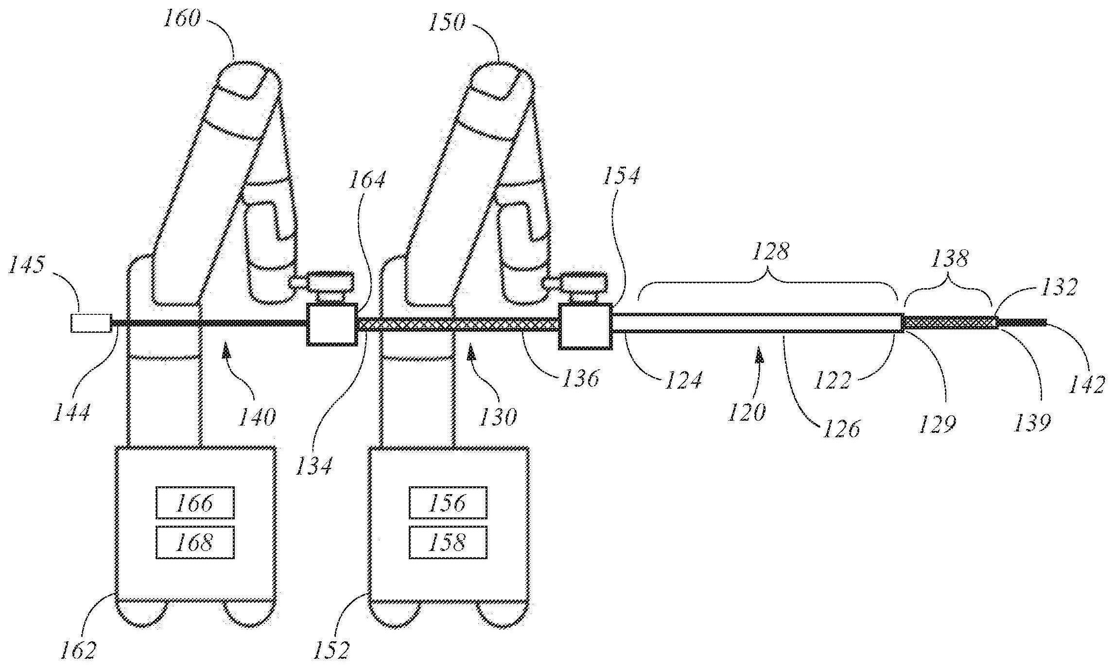
도 1은 예컨대 환자의 루멘 내에서, 소정 거리에서 의료 시술(들)을 수행하는 것을 용이하게 하도록 구성된 로봇 시스템(100)의 실시예를 도시한다. 시스템(100)은 삽입 가능 기기(140)가 삽입될 수 있는 쉬드(sheath)(120) 및 리더(leader)(130)와 같은 가요성 기기들을 포함할 수 있다. 도시된 바와 같이, 가요성 기기들의 쉬드-리더 배열에 의해, 리더(130)와 쉬드(120)는 각각 별개의 구동 메커니즘(154, 164)에 결합되고, 각 구동 메커니즘은 로봇 아암(150, 160)의 원위 단부에 결합된다.1 depicts an embodiment of a
쉬드(120)의 원위 단부(122)는 환자의 루멘(도시되지 않음) 내로 삽입되도록 구성될 수 있으며, 리더(130)의 원위 단부(132)는 쉬드(120)를 통해 작업 채널(129) 내로 삽입될 수 있고 환자의 루멘 내의 타겟 위치로 내비게이션될 수 있으며, 타겟 위치는 의료 시술(들)의 목표인 환자의 루멘의 조직 부위에 해당한다(예를 들면, 도 3 참조). 삽입 가능 기기(140)의 원위 단부(142)는 리더(130)의 작업 채널(139)을 통해 삽입되어 원위 단부(132)로 전진되어 조직 부위에 액세스하여 의료 시술(들)을 수행하도록 구성될 수 있다.The
쉬드(120)는 원위 단부(122), 근위 단부(124), 원위 단부(122)와 근위 단부(124) 사이에서 연장되는 샤프트(126), 및 샤프트(126)의 관절 운동 가능 영역(128)을 포함할 수 있다. 관절 운동 가능 영역(128)은 환자의 루멘을 통한 쉬드(120)의 내비게이션을 용이하게 하기 위해 샤프트(126)의 길이 방향 축에 대해 관절 운동될 수 있다. 원위 단부(122)는 원위 단부(122)에 대한 경로를 선택하기 위해 (예를 들면, 아래에서 보다 상세히 설명되는 하나 이상의 풀 와이어의 사용을 통해) 관절 운동 가능 영역(128)을 관절 운동시키고 샤프트(126)와 원위 단부(122)를 근위 단부(124)로부터 환자의 루멘을 통해 전진시킴으로써 환자의 루멘을 통해 안내될 수 있다. 이러한 방식으로, 원위 단부(122)는 환자의 루멘을 통해 조직 부위로 내비게이션될 수 있다. 위에서 언급한 바와 같이, 형광 투시법, x선, 및/또는 컴퓨터 축방향 단층 촬영(CT) 스캐닝을 포함하나 이에 국한되지 않는 다양한 내비게이션 보조구 및 시스템이 이 프로세스를 지원할 수 있다. 관절 운동 가능 영역(128)은 근위 단부(124)와 원위 단부(122) 사이에 위치될 수 있으며, 본 예에서는 원위 단부(122)에 인접해 있다. 이러한 배열은 환자의 루멘 네트워크를 통한 쉬드(120)의 내비게이션을 용이하게 할 수 있다.The
리더(130)는 원위 단부(132), 근위 단부(134), 원위 단부(132)와 근위 단부(134) 사이에서 연장되는 샤프트(136), 및 샤프트(136)의 관절 운동 가능 영역(138)을 포함할 수 있다. 관절 운동 가능 영역(138)은 환자의 루멘을 통한 리더(130)의 내비게이션을 용이하게 하기 위해 샤프트(136)의 길이 방향 축에 대해 관절 운동될 수 있다. 관절 운동 가능 영역(138)은 근위 단부(134)와 원위 단부(132) 사이에 위치될 수 있으며, 본 예에서는 원위 단부(132)에 인접해 있다. 이러한 배열은 환자의 루멘 네트워크를 통한 리더(130)의 내비게이션을 용이하게 할 수 있다.The
위에서 언급한 바와 같이, 리더(130)의 원위 단부(132)는 쉬드(120)의 근위 단부(124) 내로 삽입되어 적어도 부분적으로는 이에 의해 지지될 수 있다. As noted above, the
리더(130)의 원위 단부(132)는 쉬드(120)의 원위 단부(122)로부터 외부로 연장되며, 예를 들면 원위 단부(132)에 대한 경로를 선택하기 위해 (예를 들면, 아래에서 보다 상세히 설명되는 하나 이상의 풀 와이어의 사용을 통해) 관절 운동 가능 영역(138)을 관절 운동시키고 쉬드(120)의 샤프트(126)를 통해 리더(130)를 전진시킴으로써 환자의 루멘을 통해 안내될 수 있다. 쉬드(120)는 환자의 루멘을 통한 경로를 선택하기 위해 리더(130)가 전진되고 관절 운동될 수 있는 베이스를 제공할 수 있다. 쉬드(120)는 또한 리더(130)에 대한 지지를 제공하고 그 조향을 용이하게 할 수 있다. 이러한 전진 기술은 예를 들면, 조직 부위에 인접한 타겟 위치에 도달하기 위해 환자의 루멘 네트워크를 통해 리더(130)의 원위 단부(132)를 전진시키는 데 사용될 수 있다. 전진 기술은 환자의 루멘 네트워크로부터 리더(130) 및 쉬드(120)를 후퇴시키기 위해 반전될 수 있다. 이러한 방식으로, 리더(130)의 원위 단부(132)는 환자의 루멘을 통해 조직 부위로/로부터 내비게이션될 수 있다. 위에서 언급한 바와 같이, 형광 투시법, x선, 및/또는 CT 스캐닝을 포함하나 이에 국한되지 않는 다양한 내비게이션 보조구 및 시스템이 이 프로세스를 지원할 수 있다.The
도 1의 예에 도시된 바와 같이, 쉬드(120)의 근위 단부(124)는 환자의 루멘을 통해 쉬드(120)를 안내 또는 내비게이션시키도록 구성된 제1 로봇 아암(150)에 의해 지지될 수 있다. 제1 로봇 아암(150)은 베이스(152) 및 베이스로부터 연장되는 조인트들에 결합된 복수의 아암 세그먼트를 포함할 수 있으며, 이는 제1 로봇 아암(150)에 복수의 자유도를 제공한다. 예를 들어, 제1 로봇 아암(150)의 일 구현예는 7개의 아암 세그먼트에 대응하는 7의 자유도를 가질 수 있다. 몇몇 실시예에서, 제1 로봇 아암(150)은 브레이크들 및 제1 로봇 아암(150)의 위치를 유지시키기 위한 카운터 밸런스들(counter-balances)의 조합을 이용하는 조인트들을 포함한다. 카운터 밸런스들은 가스 스프링 또는 코일 스프링을 포함할 수 있다. 브레이크들, 예를 들어 페일 세이프(fail safe) 브레이크들은 기계 및/또는 전기 컴포넌트들을 포함할 수 있다. 또한, 제1 로봇 아암(150)은 중력 보조식 수동 지지형(gravity-assisted passive support type) 로봇 아암일 수 있다.As shown in the example of FIG. 1 , the
엔드 이펙터(end effector)는 제1 로봇 아암(150)에 결합되어 쉬드(120)를 제어하도록 구성된 구동 메커니즘(154)을 포함할 수 있다. 구동 메커니즘(154)은 공압, 전력, 전기 신호들, 및/또는 광 신호들을 제1 로봇 아암(150)으로부터 쉬드(120)로 전달하기 위한 커넥터들을 포함할 수 있다. 구동 메커니즘(154)은 직접 구동, 하모닉(harmonic) 구동, 기어 구동, 벨트 및 풀리, 자기(magnetic) 구동 등을 포함하는 기술을 사용하여 쉬드(120)의 포지셔닝을 조종하도록 구성될 수 있다. 도 5를 참조하여 아래에서 더 설명되는 바와 같이, 구동 메커니즘(154)은 또한 관절 운동 가능 영역(128)을 관절 운동시키기 위한 풀 와이어의 인장(tensioning)을 조종하도록 구성될 수 있다.An end effector may include a
제1 로봇 아암(150)의 베이스(152)는 동력원, 공압, 제어 및 센서 전자장치들 - 예를 들면, 중앙 처리 장치(156), 데이터 버스, 제어 회로, 및 메모리(158)와 같은 컴포넌트들을 포함함 - 및 제1 로봇 아암(150)을 동작시키기 위한 모터들과 같은 관련 액추에이터들을 포함할 수 있다. 몇몇 실시예에서, 베이스(152)는 로봇 시스템(100)을 운반하기 위한 휠들 및 휠들을 위한 휠 락/브레이크(wheel locks/brakes)를 포함한다. 외과용 로봇 시스템(100)의 이동성은 외과 수술실의 공간 제약에 대응할 뿐만 아니라 외과용 장비의 적절한 포지셔닝 및 이동을 용이하게 한다. 또한, 이동성은 제1 로봇 아암(150)이 환자, 의사, 마취의, 또는 다른 장비와 간섭되지 않도록 제1 로봇 아암(150)이 구성될 수 있게 한다. 의료 시술 중에, 사용자는 제어 장치들, 예를 들면 (도 7을 참조하여 아래에서 보다 상세히 설명되는) 커맨드 센터를 사용하여 로봇 아암(150)을 제어할 수 있다.The
(근위 단부(134)를 포함하는) 리더(130)의 근위 부분은 쉬드(120)의 작업 채널(129)을 통해서 및 환자의 루멘 내로/을 통해 리더(130)를 안내하도록 구성된 제2 로봇 아암(160)에 의해 지지될 수 있다. 제1 로봇 아암(150)과 마찬가지로, 제2 로봇 아암(160)은 베이스(162), 조인트들에서 결합된 복수의 아암 세그먼트, 브레이크들, 및/또는 제2 로봇 아암(160)의 위치를 유지시키기 위한 카운터 밸런스들을 포함할 수 있다. 제1 로봇 아암(150)의 베이스(152)와 마찬가지로, 제2 로봇 아암(160)의 베이스(162)는 동력원, 공압, 제어 및 센서 전자장치들 - 예를 들면, 중앙 처리 장치(166), 데이터 버스, 제어 회로, 및 메모리(168)와 같은 컴포넌트들을 포함함 - 및 제2 로봇 아암(160)을 동작시키기 위한 모터들과 같은 관련 액츄에이터들을 포함할 수 있다. 몇몇 실시예에서, 제2 로봇 아암의 베이스(162)는 휠들 및 휠들을 위한 락/브레이크를 포함한다. 로봇 시스템(100)의 몇몇 실시예에서, 제1 및 제2 로봇 아암(150, 160)은 동일한 베이스에 장착되거나 환자 수술대에 장착될 수 있다.The proximal portion of the leader 130 (including the proximal end 134 ) is configured to guide the
(구동 메커니즘(154)과 유사할 수 있는) 엔드 이펙터 또는 구동 메커니즘(164)이 제2 로봇 아암(160)에 결합되어 리더(130)를 제어하도록 구성될 수 있다. 구동 메커니즘(164)은 공압, 전력, 전기 신호들, 및/또는 광 신호들을 제2 로봇 아암(160)으로부터 리더(130)로 전달하기 위한 커넥터들을 포함할 수 있다. 구동 메커니즘(164)은 직접 구동, 하모닉 구동, 기어 구동, 벨트 및 풀리, 자기 구동 등을 포함하는 기술을 사용하여 리더(130)의 포지셔닝을 조종하도록 구성될 수 있다. 도 5를 참조하여 아래에서 더 설명되는 바와 같이, 구동 메커니즘(164)은 또한 관절 운동 가능 영역(138)을 관절 운동시키기 위한 풀 와이어의 인장을 조종하도록 구성될 수 있다.An end effector or drive mechanism 164 (which may be similar to the drive mechanism 154 ) may be coupled to the second
삽입 가능 기기(140)의 원위 단부(142)는 리더(130)의 근위 단부(134)에서 작업 채널(139) 내로 수동으로 삽입되도록 구성될 수 있다. 예를 들어, 삽입 가능 기기(140)의 원위 단부(144) 상의 핸들(145)은 사용자(예를 들면, 의사)에 의해 파지되어 작업 채널(139)을 따라 수술 위치로 안내될 수 있다. 핸들(145)은 샘플 또는 치료제를 획득하기 위한 돌입(plunging) 또는 후퇴 운동뿐만 아니라 조준(aiming)을 위한 관절 운동 또는 임의의 다른 적절한 운동과 같은, 원하는 의료 시술를 수행하기 위해 삽입 가능 기기(140)를 조작하기 위한 작동 메커니즘(들)을 포함할 수 있다. 삽입 가능 기기(140)의 원위 단부(142)는 샤프트들(126, 136)을 따라서 관절 운동 가능 영역들(128, 138)을 통해 리더(130)의 원위 단부(132)로 통과될 수 있다. 리더(130)의 관절 운동 가능 영역(138) 내로의 삽입 가능 기기(140)의 원위 단부(142)의 통과는, 도 2b를 참조하여 아래에 설명되는 바와 같이, 관절 운동 가능 영역(138)의 바람직하지 않은 디플렉션을 유발할 수 있다. 또한, 쉬드(120)의 관절 운동 가능 영역(128) 내로의 원위 단부(142)의 통과는 관절 운동 가능 영역(138)의 디플렉션과 유사하게, 쉬드(120)의 관절 운동 가능 영역(128)의 바람직하지 않은 디플렉션을 유발할 수 있다.The
도 2a의 예에 도시된 바와 같이, 샤프트(136)의 관절 운동 가능 영역(138)은 예시의 목적을 위해 외측 케이싱(135)에 의해 덮이지 않은 상태로 도시되어 있다. 리더(130)의 외측 케이싱(135)은 가요성 폴리머 재료(예를 들면, 폴리우레탄 또는 폴리에스테르 엘라스토머 등)를 포함할 수 있고, 리더(130) 내로의 체액의 유입을 방지하며 샤프트(136)를 따라서 환자의 루멘과의 매끄러운 인터페이스를 보장할 수 있다. 또한, 외측 케이싱(135)은 샤프트(136)에 외측 구조를 제공하는 코일형 금속 밴드(137) 위로 배치될 수 있다. 관절 운동 가능 영역(138) 내에서, 코일형 금속 밴드(137)는 예를 들면, 코일형 금속 밴드(137) 내의 코일들의 간격에 기초하여 관절 운동 가능 영역(138)이 샤프트(136)의 나머지 부분보다 더 유연하도록 구조가 이루어질 수 있다.As shown in the example of FIG. 2A ,
도 2b는 도 2a에 도시된 로봇 시스템(100)의 원위 부분의 일례를 도시한다. 파선으로 도시된 바와 같이, 원위 단부(132)는 환자의 루멘 내의 타겟 위치(118)로 내비게이션되고, 타겟 위치(118)는 의료 시술의 대상인 조직 부위의 소정 거리 내의 및/또는 이와 정렬된 리더(130)의 (원위 단부(132)를 포함하는) 원위 부분의 원하는 위치에 대응하며, 그래서 삽입 가능 기기(140)의 원위 단부(142)는 조직 부위에 액세스하기 위해 리더(130)의 원위 단부(132)로부터 연장될 수 있다. 예를 들어, 타겟 위치(118)는 적어도 부분적으로는 환자의 루멘 내의 원위 단부(132)의 위치(예를 들면, 좌표계 내의 위치), 환자의 루멘의 내비게이션 모델, 원위 단부(132)의 롤, 피치, 및/또는 요(yaw), 및/또는 관절 운동 가능 영역(138)의 관절 각도(116)로 표현될 수 있다.FIG. 2B shows an example of a distal portion of the
전술한 바와 같이, 삽입 가능 기기(140)는 조직 부위에 액세스하기 위해 리더(130)의 작업 채널(139)을 통해 전진될 수 있다. 관절 운동 가능 영역(138) 내로의 삽입 가능 기기(140)의 원위 단부(142)의 삽입 시에, 원위 단부(132)는 파선으로 도시된 타겟 위치(118)로부터 실선으로 도시된 디플렉션된 위치(119)로 디플렉션되거나 이동될 수 있다. 타겟 위치(118)와 유사하게, 디플렉션된 위치(119)는 디플렉션 각도(115)의 변화 또는 관절 운동 가능 영역(138)의 새로운 관절 각도(116a)로 나타낼 수 있다.As noted above, the
일례에서, 디플렉션된 위치(119)는 더 이상 조직 부위에 대응하지 않으며, 그래서 삽입 가능 기기(140)의 원위 단부(142)의 연장부는 리더(130)의 원위 단부(132)로부터 연장될 수는 있으나, 조직 부위에 액세스할 수 없거나 조직 부위와 오정렬될 수 있다. 예시적인 일례에서, 생검을 위한 조직 샘플의 수집 중에, 조직 부위는 약 3 cm 미만의 직경을 갖는 잠재적으로 암성의 병변(cancerous lesion)이다. 작업 채널을 통한 생검 바늘의 삽입은 타겟 위치(118)로부터 원위 단부(132)의 이동을 초래할 수 있으며, 이에 의해 로봇 시스템의 조작자에 의한 보정이 필요하게 된다. 그렇지 않으면, 생검 바늘은 병변을 놓칠 수 있고 환자의 루멘 내에서 잘못된 조직 부위를 샘플 채취할 수 있다.In one example, the deflected
다른 예에서, 디플렉션 각도(115)는 리더(130)의 굽힘 강성(flexural rigidity) 및 삽입 가능 기기(140)의 굽힘 강성에 따라 크게는 15° 이상일 수도 있다. 디플렉션 각도(115)의 크기에 영향을 줄 수 있는 다른 인자는 관절 각도(116), 삽입 가능 기기(140)의 직경, 또는 관절 운동 가능 영역(138)의 굽힘 강성을 포함한다. 따라서, 본 명세서에 기술된 시스템 및 기술의 특정 양태들은 타겟 위치(118)로부터의 리더(130)의 원위 부분의 디플렉션 또는 이동 및/또는 디플렉션을 자동으로 방지, 최소화, 및/또는 보상하는 것에 관한 것이다.In another example, the
관절 운동 가능 영역(138) 내로의 삽입 가능 기기(140)의 원위 단부(142)의 삽입으로 인한 타겟 위치(118)로부터의 원위 단부(132)의 디플렉션 외에, 원위 단부(132)는 몇몇 실시예에서 쉬드(120)의 관절 운동 가능 영역(128)을 통한 원위 단부(142)의 삽입에 의해 타겟 위치(118)를 벗어나서 디플렉션되거나 이동될 수 있다. 예를 들어, (관절 운동 가능 영역(138)의 디플렉션 각도(115)와 유사한) 관절 운동 가능 영역(138)의 각도(도시되지 않음)는 작업 채널(129) 및/또는 관절 운동 가능 영역(128) 내로의 삽입 가능 기기(140)의 삽입에 의해 디플렉션되거나 이동될 수 있다. 원위 단부(132)는 그에 따라 디플렉션되거나 이동될 수 있다. 이 디플렉션 또는 이동은 전술한 바와 같이, 관절 운동 가능 영역(138)의 디플렉션 각도(115)의 변화(있는 경우에)로부터의 디플렉션 또는 이동에 추가적일 수 있다. 따라서, 본 명세서에 기술된 시스템 및 기술의 특정 양태들은 쉬드(120)의 디플렉션 또는 이동으로 인한 타겟 위치(118)로부터의 리더(130)의 원위 부분의 디플렉션의 검출 및/또는 디플렉션 또는 이동을 자동으로 방지, 최소화, 및/또는 보상하는 것에 관한 것이다.In addition to deflection of the
도 3은 환자의 루멘 네트워크 또는 루멘(303), 예를 들면 도시된 바와 같이 폐(lung) 내의 로봇 시스템(100)의 원위 부분을 도시한다. 리더(130)의 원위 단부(132)는, 예컨대 제2 로봇 아암(160)에 의해 근위 단부(134)를 전진시키고 구동 메커니즘(164)으로 관절 운동 가능 영역(138)을 관절 운동시킴으로써 원위 단부(132)로 환자의 루멘(303)을 통한 경로를 선택함으로써, 환자의 루멘(303)을 통해 내비게이션될 수 있다. 리더(130)의 샤프트(136)는 예컨대 제2 로봇 아암(160)에 의해 쉬드(120)의 작업 채널(129)을 통해 전진될 수 있고, 원위 단부(132)는 쉬드(120)의 원위 단부(122)로부터 연장될 수 있다. 쉬드의 샤프트(126) 및 원위 단부(122)는 리더(130)의 샤프트(136)를 따라 전진됨으로써 환자의 루멘을 통해 내비게이션될 수 있다. 쉬드(120)는 그에 따라 베이스를 제공할 수 있는데, 이 베이스로부터 리더(130)가 루멘(303)을 통해 다시 전진될 수 있고 루멘(303)을 통한 경로를 선택하도록 관절 운동될 수 있다. 쉬드(120)는 또한 구동 메커니즘(154)에 의해 관절 운동됨으로써 리더(130)에 지지 및 추가적인 조향을 제공할 수 있다. 이러한 전진 기술은 리더(130)의 원위 단부(132)가 조직 부위(304)에 인접한 타겟 위치(118)에 도달하도록 루멘(303)을 통해 반복될 수 있다. 전진 기술은 루멘(303)으로부터 리더(130) 및 쉬드(120)를 후퇴시키기 위해 반전될 수 있다.3 shows a distal portion of the
삽입 가능 기기(140)의 원위 단부(142)는 리더(130)의 내부 루멘(139)을 통해서 및 (수동 및/또는 로봇식으로) 원위 단부(132)로부터 외부로 전진될 수 있다. 삽입 가능 기기(140)의 원위 단부는 이에 의해 조직 부위(304)에 액세스할 수 있다. 도 2b를 참조하여 위에서 설명된 바와 같이, 삽입 가능 기기(140)의 전진은 리더의 관절 운동 가능 영역(138) 및/또는 쉬드(120)의 관절 운동 가능 영역(128)의 디플렉션을 초래할 수 있다.The
따라서, 본 명세서에 기술된 시스템 및 기술의 특정 양태들은 타겟 위치(118)로부터의 리더(130)의 원위 단부(132)의 디플렉션의 검출 및/또는 디플렉션을 자동으로 방지, 최소화, 및/또는 보상하는 것에 관한 것이다. 예를 들어, 본 명세서에 기술된 적어도 몇몇 실시예에서의 자동 특성은 리더(130)의 원위 단부(132)(또는 쉬드(120)의 원위 단부(122))의 디플렉션에 대한 수동 보정에 비해 실질적인 시간 절감을 제공할 수 있다는 것이 이해될 것이다. 이러한 시간 절감은 수술 시간의 단축으로 인한 환자의 보다 신속한 회복 시간, 의료 시술를 수행하는 의사, 외과의, 및 직원의 피로도의 감소, 시술를 완료하는 데 필요한 시간을 단축시키고 상기 시술의 정확도를 증가시킴으로써 보다 저비용의 의료 시술, 및 의사의 상대적인 주의 집중에 의한 의료 시술 수행에 대한 오류율의 감소를 촉진할 수 있다.Accordingly, certain aspects of the systems and techniques described herein automatically prevent, minimize, and/or detect and/or deflect deflection of the
본 시스템 및 기술의 다른 이점은 디플렉션의 보정에 대한 정확도의 개선이다. 이러한 정확도의 개선은 잘못된 위치에서 수행된 의료 시술를 반복할 필요성을 배제함으로써 수술 수행에 필요한 시간을 단축시키고, 잘못된 위치에서 취해진 생검에 대한 위양성(false positives) 및 위음성(false negatives) 비율을 저감시키며, 부정확하게 또는 잘못된 위치에서 수행됨으로 인해 반복되어야 하는 시술의 횟수를 저감시키고, 전반적으로 긍정적인 환자 결과를 증가시킬 수 있다.Another advantage of the present system and technique is improved accuracy for correction of deflection. This improvement in accuracy reduces the time required to perform surgery by eliminating the need to repeat medical procedures performed in the wrong location, reduces the rate of false positives and false negatives for biopsies taken in the wrong location, It can reduce the number of procedures that must be repeated due to being performed incorrectly or in the wrong location, and increase overall positive patient outcomes.
본 시스템 및 기술의 다른 이점은 디플렉션 검출의 개선이다. 이러한 검출 속도의 개선은 잘못된 위치에서 수행된 의료 시술을 반복할 필요성을 제거할 수 있고, 그로 인해 긍정적인 환자 결과를 증가시킬 수 있다.Another benefit of the present system and technique is improved deflection detection. This improvement in detection rate may eliminate the need to repeat medical procedures performed in the wrong location, thereby increasing positive patient outcomes.
도 4a는 예를 들면 리더(130)와 같은, 가요성 기기의 원위 부분의 실시예를 도시한다. 원위 부분은 관절 운동 가능 영역(138), 원위 단부(132), 및 작업 채널(139)의 원위 개구를 포함할 수 있다. 리더(130)의 원위 부분은 리더(130)의 원위 단부(132)의 위치를 파악하기 위한 하나 이상의 추적 시스템 또는 센서 모달리티(sensor modalities)와 함께 사용하기 위한 추적 센서들을 더 포함할 수 있다. 이러한 추적 센서들 및 시스템들에 관한 추가 상세 사항들은 본 명세서의 상세 사항들 외에, 2016년 9월 17일자로 제출되고 발명의 명칭이 "관형 네트워크의 내비게이션"인 미국 출원 제15/268,238호에 기재되어 있으며, 그 전체 내용은 본 명세서에 참조로 포함되어 있다.4A shows an embodiment of a distal portion of a flexible device, such as, for example,
이들 추적 센서를 모니터링하는 추적 시스템들은 작업 채널(139) 내로의 삽입 가능 기기(140)의 삽입에 의해 또는 원위 단부의 다른 원치 않는 움직임으로부터 야기된 것과 같은 움직임을 포함하여 원위 단부(132)의 움직임을 추적 및 검출하는데 사용될 수 있다. 예를 들어, 추적 시스템은 원위 단부(132)가 시스템(100)에 의해 타겟 위치(118) 내로 내비게이션되었는지 여부, 원위 단부(132)가 타겟 위치(118)로부터 디플렉션되었는지 여부, 및/또는 타겟 위치(118)로부터의 디플렉션의 크기를 검출할 수 있다. 또한, 추적 시스템들 각각은 예를 들면, 도 7을 참조하여 아래에서 논의되는 커맨드 센터(700)와 같은 컨트롤러를 포함하거나 아니만 이와 통신할 수 있다. 컨트롤러는 아래에서 설명되는 추적 시스템들 중 임의의 것으로부터의 데이터를 사용하여 타겟 위치(118)로부터 원위 단부(132)의 측정 또는 검출된 디플렉션을 보상하기 위해 로봇 시스템(100)에 제어 신호를 발생시키기 위한 명령들이 저장된 컴퓨터 가독 매체와 통신 가능하게 결합된 프로세서를 포함할 수 있다.Tracking systems that monitor these tracking sensors include movement of the
도 4a의 예를 계속 참조하면, 다수의 가능한 추적 시스템이 이제 논의된다. 일례의 추적 시스템에서, 리더(130)의 원위 부분은 가속도계 및/또는 자이로스코프와 같은 하나 이상의 관성 센서(460)를 포함할 수 있다. 관성 센서(460)는 가속도의 변화를 검출 및/또는 측정하고 이들 측정치를 반영한 데이터 신호를 컨트롤러에 출력하도록 구성될 수 있다. 일 실시예에서, 관성 센서(460)는 가속도계를 갖는 3축 마이크로 전자 기계 시스템(microelectromechanical systems: MEMS) 기반의 센서 칩이며, 예를 들면 도4에 도시된 바와 같이 카메라(450)와 동일한 인쇄 회로 기판(PCB) 상에 또는 다른 기판 상에 리더(130)의 원위 단부(132) 근처에 결합될 수 있다. 가속도계는 원위 단부(132)의 속도와 방향을 계산하기 위해 3개의 상이한 축을 따라 선형 가속도를 측정할 수 있다. 그래서, 타겟 위치(118)를 벗어난 원위 단부(132)의 움직임은 컨트롤러에 의해 검출 및/또는 측정될 수 있다.With continued reference to the example of FIG. 4A , a number of possible tracking systems are now discussed. In an example tracking system, the distal portion of the
일례에서, 관성 센서(460)는 중력을 검출하고 지면(地面)에 대한 내시경 툴의 위치에 관한 정보를 제공한다. 관성 센서(460)가 중력 방향도 또한 측정하면, 관성 센서(460)는 리더(130)의 원위 단부(132)의 배향에 관한 절대 정보(absolute information)를 포함하는 데이터를 제공할 수 있다. 다른 예에서는, 리더(130)가 90도까지 감겨지거나 구부려지지 않으면, 2축 가속도계도 사용될 수 있다. 다른 예에서는, 가속도계의 축이 중력의 방향에 수직으로, 즉 지면에 수직으로 유지되는 경우에, 1축 센서가 유용할 수 있다. 또 다른 예에서, 관성 센서(460)는 원위 단부(132)의 회전 속도를 측정하도록 구성된 자이로스코프를 포함할 수 있으며, 원위 단부(132)의 회전 속도는 그리고 나서 리더(130)의 관절 운동을 계산하는데 사용될 수 있다.In one example,
관성 센서 판독 값들은 디지털 또는 아날로그 신호들을 사용하여 통신 프로토콜을 통해 컨트롤러로 전송될 수 있다. 신호는 배선을 통해 카테터의 근위 단부로 및 그곳으로부터 처리를 위해 컨트롤러로 전송될 수 있다. 타겟 위치(118)를 벗어난 원위 단부(132)의 움직임은 컨트롤러에 의해 검출 및/또는 측정될 수 있다.Inertial sensor readings can be sent to the controller via a communication protocol using digital or analog signals. Signals may be transmitted via wires to and from the proximal end of the catheter to the controller for processing. Movement of the
다른 예시적인 추적 시스템으로서, 카메라(450)가 또한 광학 추적 시스템의 일부로서 사용될 수 있다. 카메라(450)는 몇몇 실시예에서 전하 결합 소자(charge coupling device: CCD), 또는 원위 단부(132)에 근접하게 연장되는 광섬유 케이블이다. 카메라(450)로부터의 이미지들은 환자의 루멘과 같은 해부학적 공간들을 통해 리더(130)의 원위 단부(132)를 내비게이션시키고 타겟 위치(118)에 도달하는 데 이상적일 수 있다. 원위 단부(132)는 LED와 같은 광원을 또한 포함할 수 있다. LED와 함께, 카메라(450)는 예를 들면, 환자의 루멘 내에서의 내비게이션을 보조하기 위한 실시간 비디오를 캡처하는데 사용될 수 있다. 점액과 같은 내부 체액은 내비게이션시 문제를 일으킬 수 있다. 따라서, 원위 단부(132)는 또한 카메라 렌즈의 관주(irrigation) 및/또는 흡입(aspiration)을 위한 컴포넌트(들)와 같은, 카메라(450)를 클리닝하기 위한 컴포넌트(들)를 포함할 수 있다.As another example tracking system,
내비게이션 외에, 카메라는 원위 단부(132)의 디플렉션을 검출하는데 및/또는 이러한 디플렉션의 크기를 측정하는데 사용될 수 있다. 광학 추적 시스템에서, 카메라(450)로부터의 출력 또는 데이터 신호는 컨트롤러와 결합될 수 있으며, 이에 의해 데이터 신호는 타겟 위치(118)를 벗어난 원위 단부(132)의 디플렉션을 검출 및/또는 측정하기 위해 처리될 수 있다.In addition to navigation, the camera may be used to detect and/or measure the magnitude of deflections of the
리더(130)의 원위 부분은 또한 원위 단부(132) 상에 하나 이상의 전자기(electromagnetic: EM) 추적기 또는 센서(484)를 포함할 수 있으며, 이는 도 4b에 도시된 EM 추적 시스템(480)과 함께 사용될 수 있다. EM 추적 시스템(480)은 전자기장 내의 센서의 위치의 실시간 표시를 제공하기 위해 발생된 전자기장(EM 필드)과 함께 EM 센서(484)를 사용할 수 있다. 그래서, 원위 단부(122)의 위치는 EM 추적 시스템으로 추적될 수 있으며, 원위 단부(132)는 하나 이상의 EM 센서(484)를 포함한다. 게다가, 타겟 위치(118)를 벗어난 임의의 움직임 또는 디플렉션이 검출될 수 있으며 및/또는 디플렉션의 크기는 추적 시스템(480)으로부터의 데이터 신호를 사용하여 측정될 수 있다.The distal portion of the
EM 기반의 추적에서는, 정적 EM 필드 발생기(486)가 EM 필드를 발생시킨다. EM 필드 발생기(486)는 저강도 자기장을 발생시키기 위해 환자(101)에 가깝게 배치될 수 있다. 예를 들어, 도 4b에 도시된 바와 같이, 필드 발생기(486)는 환자(101)의 신체를 지지하기 위한 환자 인터페이스 위치(112) 상에 배치될 수 있다. 예를 들어, 환자 인터페이스 위치(112)는 환자(101)를 위한 지지 플랫폼일 수 있으며, 필드 발생기는 환자의 아래에 배치될 수 있다. 다른 예에서, 필드 발생기는 로봇 아암에 고정될 수 있거나 환자 인터페이스 위치(112)의 측면의 주위에 배치될 수 있다.In EM-based tracking, a static EM field generator 486 generates the EM field. An EM field generator 486 may be placed proximate the
정적 EM 필드 발생기(486)는 EM 센서(484)의 센서 코일에 소전류(small current)를 유도하며, 이는 센서와 발생기 사이의 거리 및 각도와 상관된다. 그리고 나서 전기 신호는 인터페이스 유닛(온칩(on-chip) 또는 PCB)에 의해 디지털화되어, 케이블/배선을 통해 시스템 카트로 되전송되며 그리고 나서 커맨드 센터로 전송될 수 있다. 데이터는 그리고 나서 현재 데이터를 해석하고 송신기 또는 필드 발생기(486)에 대한 EM 센서(484)의 정확한 위치 및 배향을 계산하기 위해 처리될 수 있다. 이들 EM 센서의 위치들을 또한 계산하기 위해 리더(130)의 상이한 위치에, 예를 들면 관절 운동 가능 영역(138) 상에 복수의 센서가 사용될 수 있다.The static EM field generator 486 induces a small current in the sensor coil of the
그래서, 인공적으로 발생된 EM 필드로부터의 판독 값들에 기초하여, EM 센서(484)는 환자의 해부학적 구조를 통해 이동함에 따라 필드 강도의 변화를 검출할 수 있다. EM 센서(484)로부터의 데이터 신호는 해석 및 분석을 위해 리더(130)의 샤프트를 따라 컨트롤러(488)로 또는 이와 달리, 컨트롤러 또는 커맨드 센터(700)로 전송될 수 있다. EM 센서(484)로부터의 판독 값들을 사용하여, 디스플레이 모듈들은 조작자가 검토할 수 있도록 미리 생성된 3차원 모델 내에서 EM 센서의 상대 위치를 디스플레이할 수 있다.Thus, based on readings from the artificially generated EM field, the
로봇 시스템(100)의 원위 부분의 디플렉션을 검출 및 측정하기 위해 다양한 센서 및 추적 시스템이 사용될 수 있으나, 센서(들)의 선택은 적어도 부분적으로는 (i) 내시경 툴 내의 센서(들)의 크기 및(ii) 센서(들)의 제조 및 쉬드(120) 내에의 통합 비용에 기초할 수 있다.Although a variety of sensors and tracking systems may be used to detect and measure deflection of the distal portion of the
한 세트의 생리학적 센서(490)가 환자의 생리학적 움직임을 추적하는데 사용될 수 있다. 예를 들어, 생리학적 센서들(490)은 호흡 중에 흉부 표면의 변위를 추정하는 것을 돕기 위해 환자의 신체에 위치된 하나 이상의 관성 센서를 포함할 수 있다. 다른 예에서, 생리학적 센서들(490)은 환자의 신체에 배치되어 EM 추적 시스템(480)과 함께 호흡 주기의 흡기(들숨)와 호기(날숨) 단계들을 측정하는데 사용되도록 구성되는 EM 패치 또는 EM 호흡 센서들을 포함할 수 있다. 다른 예에서는, 호흡에 의해 초래되는 변위를 추적하기 위해 환자의 신체에(예를 들면, 환자의 루멘의 영역에) 다수의 추가적인 EM 패치 센서가 제공될 수 있다. 몇몇 실시예에서, 생리학적 센서들(490)의 데이터는 각 EM 패치 센서에 대해, 시간 경과에 따른 EM 필드에서의 센서의 위치들을 나타내는 시간 종속적인(time-dependent) 위치 데이터를 포함할 수 있다. 이들 위치에서의 상이한 변위를 추적하기 위해 다수의 상이한 EM 패치 센서가 신체 상에서 이격될 수 있다. 예를 들어, 폐의 주변부는 호흡으로 인해 중앙 기도(central airways)보다 더 큰 움직임을 보일 수 있으며, 다수의 EM 패치 센서를 제공하는 것은 이러한 움직임의 영향의 보다 정밀한 분석을 가능케 할 수 있다. 또한, 리더(130)의 원위 단부(132)는 루멘(303)의 상이한 영역들을 통해 이동하며, 그래서 이들 상이한 영역들을 통해 이동함에 따라 환자의 호흡으로 인한 변하는 수준의 변위를 겪게 된다. 데이터 필터링 기술은 리더(130)의 원위 단부(132)의 대략적인 위치를 추가적인 EM 패치 센서들 중 하나 이상과 상관시킬 수 있으며, 예를 들면 내시경 위치 신호의 호흡 움직임 아티팩트 성분(들)의 필터링/제거를 통해, 기도의 움직임으로 인한 내시경 위치 신호 내의 노이즈 또는 아티팩트를 보정하기 위해 이들 특정의 추가적인 EM 패치 센서들의 식별된 변위 크기를 사용할 수 있다. 생리학적 센서들(490)의 이 EM 패치 센서의 실시예는 2017년 3월 31일자로 제출되고 발명의 명칭이 "생리학적 노이즈를 보상하는 루멘 네트워크들의 내비게이션을 위한 로봇 시스템"인 미국 가특허 출원 제62/480,257호에 더 기재되어 있으며, 상기 특허 문헌 전체는 본 명세서에 참고로 통합되어 있다.A set of
다른 예에서, 생리학적 센서들(490)은 기도의 영역(예를 들면, 루멘의 영역(103))에서 환자의 신체에 배치되어 호흡 주기의 흡기와 호기 단계들을 측정하는 데 사용되도록 구성되는 음향 또는 다른 유형의 호흡 센서를 포함한다. 다른 예에서, 생리학적 센서들(490)은 환자의 신체의 이미지들의 스트림을 캡처할 수 있는 광 센서(예를 들면, 이미징 디바이스)를 포함할 수 있으며, 이들 이미지는 호흡 단계 및/또는 변위를 식별하기 위해 분석될 수 있다. 몇몇 구현예에서, 환자(101)는 시술 중에 인공 호흡기의 도움으로 호흡하고 있을 수 있으며, 인공 호흡기(및/또는 인공 호흡기와 통신 가능하게 결합된 디바이스)는 호흡 주기의 흡기 및 호기 단계들을 나타내는 데이터를 제공할 수 있다.In another example,
생리학적 센서들로부터의 데이터는 전술한 하나 이상의 추적 시스템으로부터의 데이터와 함께 컨트롤러 또는 커맨드 센터(700)에 의해 사용될 수 있다. 생리학적 센서들로부터의 이 데이터를 비교함으로써, 환자의 움직임은 추적 시스템들로부터의 데이터에서 필터링될 수 있으며, 그래서 필터링된 데이터는 (예를 들면, 호흡 주기의 흡기 및 호기 단계들 중의) 환자의 움직임이라기 보다는 기기의 삽입으로 인한 디플렉션으로부터의 리더(130)의 원위 단부(132)의 움직임을 나타낸다.Data from physiological sensors may be used by the controller or
도 4c는 그 원위 단부(142) 상에 EM 센서(482)를 구비한 삽입 가능 기기(140)의 실시예를 도시한다. 삽입 가능 기기(140)가 리더(130)의 작업 채널(139)을 통해 수동으로 삽입되는 로봇 시스템(100)과 같은 몇몇 실시예에서, EM 센서(482)는 리더(130)를 통해서 및/또는 환자의 루멘 내에서 삽입 가능 기기(140)의 원위 단부(142)의 진행을 추적하기 위해 EM 추적 시스템(480)과 함께 사용될 수 있다. 원위 단부(142)의 위치를 나타내는 데이터와 같은, EM 센서(482)로부터의 데이터는 또한 본 명세서에 기술된 다른 추적 메커니즘들 중 임의의 것과 함께 사용될 수 있다. 예를 들어, EM 센서(482)로부터의 데이터는 예를 들면, 리더(130) 내의 EM 센서의 위치 또는 원위 단부(132)에 대한 그 근접성에 기초하여 본 명세서에 기술된 추적 시스템들 중 임의의 것을 초기화 또는 종료하는데 사용될 수 있다. 다른 예에서, 센서(482)로부터의 데이터는 도 5 및 도 9를 참조하여 아래에서 설명되는 바와 같이, 관절 운동 가능 영역(138)의 타이밍 조정의 인자(factor)로서 사용될 수 있다. 다른 예에서, 센서(482)로부터의 데이터는 원위 단부(142)가 관절 운동 가능 영역(138)에 언제 진입하게 될 지를 알기 위해 관절 운동 가능 영역(138)으로부터의 원위 단부(142)의 거리를 계산하는데 사용될 수 있다. 다른 예에서, 센서(482)로부터의 데이터는 원위 단부(142)가 관절 운동 가능 영역(138)에 언제 진입하게 될 지를 알기 위해 원위 단부(142)의 궤적을 결정하는데 사용될 수 있다. 몇몇 실시예에서는, EM 센서(482) 대신에 또는 이에 부가하여, 삽입 가능 기기(140)는 종래의 방사선 기반의 내비게이션 보조구(예를 들면, 형광 투시법, x선, 컴퓨터 축방향 단층 촬영 스캔 등)를 사용하여 추적되거나 볼 수 있는 금속제의 방사선 비투과성(radio-opaque) 밴드를 포함할 수 있다.4C shows an embodiment of an
몇몇 실시예에서, 삽입 가능 기기(140)는 식별 태그(identification tag)를 포함할 수 있으며, 이 태그는 특정 삽입 가능 기기(140)에 관한 정보에 대응하거나 이를 포함하고, 예를 들면 기기의 물리적 특성들과 같은 정보를 포함한다. 몇몇 실시예에서, 로봇 시스템(100)은 태그에 기초하여 삽입 가능 기기(140)를 자동으로 식별할 수 있다. 예를 들어, 태그는 RFID 태그, 바코드 등일 수 있다. 몇몇 실시예에서, 삽입 가능 기기(140)와 연관된 물리적 특성들은 식별자(예를 들면, RFID 태그)에 인코딩될 수 있으며, 작업 채널(139) 내로의 삽입 가능 기기(140)의 삽입으로 인한 리더(130)의 예상되는 디플렉션 응답을 결정하기 위해 로봇 시스템(100)에 의해 고려될 수 있다.In some embodiments, the
도 5는 하나 이상의 풀 와이어(556)를 제어하도록 구성된 구동 메커니즘(500)의 실시예를 도시한다. 예를 들어, 구동 메커니즘(500)은 구동 메커니즘들(154 또는 164), 또는 본 명세서에 기술된 다른 로봇 시스템들 중 하나 이상에 대응할 수 있다. 여기서는 리더(130)를 참조하여 설명되지만, 구동 메커니즘의 실시예들은 또한 쉬드(120) 또는 임의의 다른 가요성 기기와 함께 사용될 수도 있다.5 shows an embodiment of a
구동 메커니즘(500)은 근위 단부(134)로부터 리더(130)를 조종하기 위한 하나 이상의 풀 와이어(556)를 제어하도록 구성된다. 원위 단부(132)의 위치 및 관절 운동 가능 영역(138)을 제어하고 환자의 루멘을 통해 리더(130)의 샤프트(136)를 전진시킴으로써, 리더(130)는 예컨대 시스템(100)의 제어 센터에서의 의사의 입력에 응답하여 타겟 위치(118)로 내비게이션될 수 있다. 풀 와이어들(556)은 관절 운동 가능 영역(138)의 관절 각도(116) 및 방향을 제어할 수 있다. 리더(130)의 원위 단부(132)가 일단 타겟 위치(118)에 있게 되면, 몇몇 실시예에서 풀 와이어들(556)은 예를 들면, 도 2b를 참조하여 위에서 설명된 타겟 위치(118)에 대응하는 원하는 위치 또는 배향으로 원위 단부를 유지시키기 위해 제자리에 로킹(locking)될 수 있다. 풀 와이어들을 로킹하는 것은 리더(130)를 움직이는데 필요한 힘이 증가되도록 풀 와이어(556)의 장력을 증가시키는 것을 포함할 수 있다.The
풀 와이어들(556)은 리더(130)의 종방향의 길이를 따라 연장될 수 있다. 몇몇 실시예에서, 풀 와이어들(556)은 리더(130)의 관절 운동 가능 영역에 대해 리더(130) 내에서 원위에 부착된다. 풀 와이어들은 하나의 풀 와이어의 장력을 증가시키면 그 풀 와이어의 방향으로 관절 운동 가능 영역이 관절 운동을 하는 경향이 있도록, 리더(130)의 샤프트(136)의 외주(periphery) 주위에 배치될 수 있다. 예를 들면, 각 기본 방향(cardinal direction)에 하나의 풀 와이어가 있도록 4개의 풀 와이어가 샤프트(136) 주위에 균등하게 이격될 수 있다.The
풀 와이어들(556)은 예를 들면, 스테인레스 스틸, 케블라(Kevlar), 텅스텐, 탄소 섬유 등과 같은 금속 및 비금속 재료 양자 모두를 포함할 수 있다. 리더(130)는 풀 와이어들에 의해 가해지는 힘에 응답하여 비선형 거동을 나타낼 수 있다. 비선형 거동은 리더(130)의 샤프트(126)의 강성 및 압축성뿐만 아니라 상이한 풀 와이어들 사이의 느슨함(slack) 또는 강성의 변동성에 기초할 수 있다.Pull
구동 메커니즘(500)은, 각각 기어 박스(552)에 대응하며 이에 회전 가능하게 결합된 모터들(551)을 포함할 수 있다. 풀 와이어들(556)은 기어 박스들(552)로부터 연장되는 샤프트들(553)에 대응되게 결합될 수 있다. 샤프트들(553)은 대응하는 모터들(551)의 회전에 의한 샤프트들(553)의 회전으로부터 풀 와이어들(556)에 인장력을 가하도록 구성될 수 있다. 풀 와이어들(556)은 풀 와이어들의 단부들을 샤프트들에 고정하고 샤프트들(553)의 회전 운동을 통해 풀 와이어들을 따라 인장력을 가하도록 구성된 풀리들(555)을 통해 샤프트들(553)과 연결될 수 있다. 이와 달리, 풀 와이어들(556)은 풀리들(555)의 유무에 관계없이 출력 샤프트들53)에 직접 부착될 수도 있다.
도 5의 예에 도시된 바와 같이, 풀리들(555)은 모터들(551)의 출력 샤프트들(553)과 길이 방향으로 정렬되고 동심(同心)을 이룰 수 있다. 풀리들(555)의 스플라인들(splines)은 출력 샤프트(553) 상의 스플라인들과 정렬되어 로킹되도록 설계될 수 있다. 몇몇 실시예에서, 스플라인들은 리더(130)가 구동 메커니즘(500)과 정렬되는 단일 배향이 존재하도록 설계된다. 정렬 상태로 로킹되면, 샤프트(553)와 풀리(555)의 회전은 리더(130) 내의 풀 와이어(556)를 인장 상태가 되게 하며, 그에 따라 리더(130)의 관절 운동 가능 영역(138)의 관절 운동을 발생시킨다.As shown in the example of FIG. 5 , the
몇몇 실시예에서, 구동 메커니즘(500)은 모터들(551)의 회전 및 풀 와이어들(556)의 인장을 제어하기 위한 컨트롤러를 더 포함하거나 외부 컨트롤러(예를 들면, 아래에서 보다 상세히 설명되는 도 7의 커맨드 센터(700))와 통신 가능하게 결합될 수 있다. 몇몇 실시예에서, 구동 메커니즘(500)은 출력 샤프트들의 회전 위치, 속도, 및/또는 가속도를 측정하기 위해 샤프트들(553)과 결합된 회전 인코더들을 포함한다. 몇몇 실시예에서, 컨트롤러는 구동 메커니즘의 하우징 또는 구동 메커니즘(500)이 장착되는 로봇 아암 내에서 구동 메커니즘(500) 상에 탑재된다. 컨트롤러는 모터들(551)과 결합될 수 있으며, 하나 이상의 풀 와이어(556)의 인장을 제어하기 위해 컴퓨터 가독 매체에 저장된 명령들을 실행하기 위한 프로세서로 구성될 수 있다.In some embodiments,
컨트롤러는 컴퓨터 가독 매체에 저장된 명령들을 실행하기 위한 프로세서를 포함할 수 있음에 유의하자. 컴퓨터 가독 매체는 전술한 추적 시스템들 중 임의의 것으로부터의 데이터를 사용하여 타겟 위치(118)로부터 원위 단부(132)의 측정 또는 검출된 디플렉션을 보상하기 위해 로봇 시스템에 제어 신호를 발생시키기 위한 명령들이 저장될 수 있다. 예를 들어, 명령들은 프로세서가 데이터를 처리하게 하고 구동 메커니즘들(154, 164) 중 어느 하나 또는 양자 모두를 사용하여 복수의 풀 와이어(556) 중 특정 풀 와이어(들)에 대한 인장을 조정하기 위한 제어 신호를 발생시키게 할 수 있다.Note that the controller may include a processor for executing instructions stored in the computer-readable medium. The computer readable medium is configured to generate a control signal to the robotic system to compensate for detected or measured deflection of the
몇몇 실시예에서, 제어 신호의 명령들은 삽입 가능 기기(140)의 원위 단부(142)가 관절 운동 가능 영역(138)을 통해 삽입되기 전에 드라이버(500)에 의해 실행된다. 이러한 선제적 모델 또는 접근법에서, 원위 단부(132)는 타겟 위치(118)를 벗어나서 디플렉션될 수 있으나 기기(140)가 관절 운동 가능 영역을 통해 연장될 때 복수의 풀 와이어(556)의 인장을 조정함으로써 타겟 위치(118)로 결국 복귀하게 된다. 다른 예에서, 제어 신호의 명령들은 삽입 가능 기기(140)의 원위 단부(142)가 관절 운동 가능 영역(138)을 통해 삽입되고 난 후에 실행될 수도 있다. 이러한 모델 또는 접근법에서, 원위 단부(132)는 복수의 풀 와이어(556)의 인장을 조정함으로써 기기(140)가 관절 운동 가능 영역을 통해 연장되고 난 후에 타겟 위치(118)로 복귀된다. 또 다른 실시예에서, 제어 신호의 명령들은 기기(140)의 원위 단부(142)가 관절 운동 가능 영역(138)을 통해 삽입될 때 실행될 수도 있다. 그래서, 원위 단부(132)는 원위 단부(142)의 전진에 맞춰서 복수의 풀 와이어(556)의 인장을 조정함으로써 삽입 가능 기기(140)의 전진 중에 실질적으로 타겟 위치(118)에 유지될 수 있다. 이들 기술 중 임의의 것이 EM 센서(182)로부터의 데이터와 같은, 삽입 가능 기기(140)의 원위 단부(142)의 위치를 나타내는 데이터와 함께 수행될 수 있다.In some embodiments, the instructions of the control signal are executed by the
일 실시예에서, 제어 신호는 원위 단부(132)가 타겟 위치(118)로 복귀될 때까지 구동 메커니즘(500)에 의해 하나 이상의 풀 와이어(556)의 장력이 점진적으로 증가되도록 하는 명령들을 포함할 수 있다. 예를 들어, 장력은 원위 단부(132)의 위치를 결정하기 위해 카메라(450)를 사용하는 광학 추적 시스템에 의해 측정 또는 추적됨에 따라 타겟 위치(118)에 도달할 때까지 증가될 수 있다. 다른 예로서, 장력은 원위 단부(132)의 위치를 결정하기 위한 EM 추적 시스템(480) 또는 관성 추적 시스템에 의해 측정 또는 추적됨에 따라 타겟 위치(118)에 도달할 때까지 증가될 수 있다. 몇몇 경우에, 풀 와이어의 인장은 가요성 기기를 축 방향으로 압축할 수 있으며, 그에 따라 가요성 기기의 원위 길이를 단축시킬 수 있다. 이러한 경우에, 제어 신호는 가요성 기기가 축 방향 압축을 보정하는 거리만큼 해부학적 구조에 삽입되게 함으로써 이러한 단축을 보상할 수 있다.In one embodiment, the control signal may include instructions to cause the tension of the one or
구동 메커니즘(500)은 리더(130)의 원위 부분의 움직임 및 위치를 모니터링하기 위한 장력 감지 시스템을 포함할 수 있다. 이 장력 감지 시스템은 리더(130)의 원위 단부(132)의 디플렉션에 의해 야기된 풀 와이어들(556)의 인장의 변화를 검출함으로써 이러한 디플렉션 또는 움직임을 검출 및/또는 측정하도록 구성될 수 있다. 예를 들어, 구동 메커니즘(500)은 풀 와이어들(556) 중 특정 풀 와이어들을 장력의 증가 또는 감소에 대해 모니터링하기 위해 이들 특정 풀 와이어들을 모니터링할 수 있다.The
예를 들어, 구동 메커니즘(500)은 풀 와이어(들)(556)의 인장에 있어서의 임의의 측정된 변화에 기초하여 풀 와이어(들)(556)의 디플렉션을 검출/측정하기 위한 하나 이상의 전기 스트레인 게이지(554)를 포함할 수 있다. 예를 들면 특정 실시예들에서, 스트레인 게이지(554)는 모터들(551) 각각에 대응하는 모터 마운트(558)와 스트레인 게이지 마운트(557) 사이에 결합된다. 스트레인 게이지들(554)은 스트레인 게이지 마운트(557)에 포팅(potted) 및 납땜(soldered)될 수 있고 각각 모터 마운트들(558)에 스크류들을 사용하여 부착될 수 있다. 스트레인 게이지들(554)은 사이드 스크류들을 사용하여 그 개개의 모터 마운트에 적소에 고정될 수 있다. 스트레인 게이지들(554)의 게이지 배선은 스트레인 게이지 마운트(557)에 대한 모터 마운트(558)에 의한 수평 변위로 측정되는 구동 메커니즘의 임의의 수직 스트레인 또는 플렉스(flex)를 검출하기 위해 수직으로 배치될 수 있다. 스트레인의 양은 스트레인 게이지(554)의 전체 수평 폭에 대한 스트레인 게이지(554)의 팁(tip)의 수평 변위의 비(ratio)로서 측정될 수 있다. 따라서, 스트레인 게이지(554)는 궁극적으로 풀 와이어(556)에 의해 샤프트(553)에 가해지는 힘을 측정할 수 있다.For example, the
스트레인 게이지들(554)은 임의의 풀 와이어(556)의 인장의 임의의 변화가 검출 및 측정될 수 있도록 구성될 수 있다. 구동 메커니즘(500)은 스트레인 게이지들(554)에서 측정된 스트레인이 원위 단부(132)의 위치 및/또는 관절 운동 가능 영역(128)의 디플렉션 각도(116)와 같은 리더(130)의 위치와 상관(correlated)될 수 있도록 교정될 수 있다. 그래서 원위 단부(132)의 위치의 임의의 변화가 검출 및/또는 측정될 수 있다.Strain gauges 554 may be configured such that any change in tension of any
스트레인 게이지(554) 및/또는 스트레인 게이지(554)와 결합된 회로로부터의 데이터 신호는 (예를 들면, 도 5에 도시된 구동 메커니즘(500) 또는 도 7의 커맨드 센터(700) 내의) 컨트롤러로 전달될 수 있다. 이 데이터 신호는 풀 와이어(들)(556)의 인장, 풀 와이어(들)(556)의 움직임, 및/또는 쉬드(120)의 움직임의 변화를 나타내는 데이터를 포함할 수 있다. 따라서, 예컨대 작업 채널(139) 내에의 또는 리더(130)의 관절 운동 가능 영역(138)을 통한 삽입 가능 기기(140)의 삽입에 의한 리더(130)의 디플렉션은 구동 메커니즘(500) 또는 그 컴포넌트(들)에 의해 검출 및/또는 측정될 수 있다.Data signals from
도 6a는 로봇 시스템(600)의 실시예를 도시한다. 로봇 시스템(100)과 유사하게, 시스템(600)은 쉬드(620), 리더(630), 및 삽입 가능 기기(640)를 포함할 수 있다. 리더(630)는 환자의 루멘(도시되지 않음) 내에 삽입되어 환자의 루멘 네트워크 내에서 내비게이션되도록 구성된다. 예를 들어, 쉬드(620) 및 리더(630)는 각각 전술한 쉬드(120) 및 리더(130)와 동일하거나 유사한 구조 및 역학(mechanics)을 가질 수 있다.6A shows an embodiment of a
리더(630)는 원위 단부(632), 근위 단부(634), 원위 단부(632)와 근위 단부(634) 사이에서 연장되는 샤프트(636), 및 샤프트(636)의 관절 운동 가능 영역(638)을 포함할 수 있다. 관절 운동 가능 영역(638)은 쉬드(620)의 원위 단부(622)로부터 연장되고 난 후 환자의 루멘을 통해 리더(630)의 내비게이션을 용이하게 하기 위해 샤프트(636)에 대해 관절 운동되도록 구성된다. 원위 단부(632)는 원위 단부(632)에 대한 경로를 선택하기 위해 관절 운동 가능 영역(638)을 관절 운동시키고 샤프트(636)와 원위 단부(632)를 근위 단부(634)로부터 환자의 루멘을 통해 전진시킴으로써 환자의 루멘을 통해 안내될 수 있다. 상기와 유사하게, 쉬드(620)는 리더(630)와 함께 전진될 수 있고, 예컨대 관절 운동 가능 영역(638)을 관절 운동시키고 리더(630)를 더욱 전진시키기 위해 이에 대한 지지를 제공할 수 있다. 이러한 방식으로, 원위 단부(632)는 환자의 루멘을 통해 타겟 위치(예를 들면, 도 2b의 타겟 위치(118) 참조)로 내비게이션될 수 있다. 관절 운동 가능 영역(638)은 근위 단부(634)와 원위 단부(632) 사이에 위치되고, 본 예에서는 원위 단부(632)에 인접해 있다. 이러한 배열은 환자의 루멘 네트워크를 통한 리더(630)의 내비게이션을 용이하게 할 수 있다. 리더(130)의 원위 단부(132)와 같이, 리더(130)는 도 4a 내지 도 5와 관련하여 설명된 것들과 같은, 환자의 루멘을 내비게이션하기 위한 센서들을 포함할 수 있다. 전술한 추적 시스템들 중 임의의 것이 원위 단부(632)의 위치를 추적하거나 위치의 변화를 검출하는데 사용될 수 있다.The
도 1a에 도시된 쉬드(120)와 유사하게, 도 6a에 도시된 쉬드(620)는 원위 단부(622), 근위 단부(624), 원위 단부(622)와 근위 단부(624) 사이에서 연장되는 샤프트(626), 및 샤프트(626)의 관절 운동 가능 영역(628)을 포함할 수 있다. 관절 운동 가능 영역(628)은 환자의 루멘을 통한 쉬드(620)의 내비게이션을 용이하게 하고 리더(630)에 지지를 제공하기 위해 샤프트(626)에 대해 관절 운동될 수 있다.Similar to the
쉬드(620)의 근위 단부(624)를 포함하는 근위 부분은 환자의 루멘을 통해 쉬드(620)를 안내 또는 내비게이션시키도록 구성되고 구동 메커니즘(654)과 결합된 제1 로봇 아암(650)에 의해 지지될 수 있다. 제1 로봇 아암(650) 및 구동 메커니즘(654)은 로봇 시스템(100)에서 위에서 논의된 제1 로봇 아암(150) 및 구동 메커니즘(154)과 유사한 구조적 및 기능적 특징들을 포함할 수 있다. 제1 로봇 아암(650)은 베이스(652) 및 베이스(652)로부터 연장되는 조인트들에서 결합된 복수의 아암 세그먼트, 동력원, 공압, 제어 및 센서 전자장치들 - 예를 들면, 중앙 처리 장치(656), 데이터 버스, 제어 회로, 및 메모리(658)와 같은 컴포넌트들을 포함함 - 및 제1 로봇 아암(650)을 동작시키기 위한 모터들과 같은 관련 액추에이터들을 포함할 수 있다. 베이스(652)는 로봇 시스템(600)을 운반하기 위한 휠들 및 휠들을 위한 휠 락/브레이크를 포함할 수 있다. 도 5와 관련하여 위에서 더 설명된 바와 같이, 구동 메커니즘(654)은 또한 관절 운동 가능 영역(628)을 관절 운동시키기 위한 풀 와이어들의 인장을 조종할 수 있다.The proximal portion, including the
리더(630)의 근위 단부(634)를 포함하는 근위 부분은 쉬드(620)의 샤프트(626)의 루멘을 통해서 및 환자의 루멘 내로 리더(630)를 안내 또는 내비게이션시키도록 구성된 제2 로봇 아암(660)에 의해 지지될 수 있다. 제1 로봇 아암(650)과 마찬가지로, 제2 로봇 아암(660)은 베이스(662), 조인트들에서 결합된 복수의 아암 세그먼트, 브레이크들, 및/또는 제2 로봇 아암(660)의 위치를 유지시키기 위한 카운터 밸런스들을 포함할 수 있다.The proximal portion comprising the
리더(630)를 제어하기 위해 엔드 이펙터 또는 구동 메커니즘(664)이 제2 로봇 아암(660)과 결합될 수 있다. 구동 메커니즘들(154, 164)과 같이, 구동 메커니즘(664)은 리더(630)에 대한 커넥터들을 포함하고 리더(630)의 포지셔닝을 조종할 수 있다. 도 5와 관련하여 위에서 더 설명된 바와 같이, 구동 메커니즘(664)은 또한 관절 운동 가능 영역(638)을 관절 운동시키기 위한 풀 와이어들의 인장을 조종할 수 있다. 제2 로봇 아암(660)의 베이스(662)는 제1 로봇 아암(150)의 베이스(152)와 유사하게, 동력원, 공압, 제어 및 센서 전자장치들 - 중앙 처리 장치(666), 데이터 버스, 제어 회로, 및 메모리(668) - 및 제2 로봇 아암(660)을 동작시키기 위한 모터들과 같은 관련 액츄에이터들을 포함할 수 있다. 시술 중에, 사용자는 제어 장치, 예를 들면 커맨드 센터를 사용하여 제2 로봇 아암(660)을 제어할 수 있다.An end effector or
유사하게, 삽입 가능 기기(640)의 근위 단부(644)는 제3 로봇 아암(670) 및/또는 기기 매니퓰레이터(674)에 의해 지지될 수 있으며, 삽입 가능 기기(640)를 안내하고 의료 시술를 수행하기 위해 삽입 가능 기기(640)를 제어하도록 구성될 수 있다. 제3 로봇 아암(670) 및 기기 매니퓰레이터(674)는 제1 및 제2 로봇 아암(650, 660) 및 로봇 시스템(100)의 로봇 아암들과 유사한 구조적 및 기능적 특징들을 포함할 수 있다. 하지만, 여기서 삽입 가능 기기(640)는 리더(630)의 작업 채널(639) 내에 삽입되어 이들 따라 안내된다. 제1 로봇 아암(650)과 마찬가지로, 제3 로봇 아암(670)은 베이스(672), 조인트들에서 결합된 복수의 아암 세그먼트, 브레이크들, 및/또는 제3 로봇 아암(670)의 위치를 유지시키기 위한 카운터 밸런스들을 포함할 수 있다. 제3 로봇 아암(670)의 베이스(672)는 동력원, 공압, 제어 및 센서 전자장치들 - 예를 들면, 중앙 처리 장치(676), 데이터 버스, 제어 회로, 및 메모리(678)와 같은 컴포넌트들을 포함함 - 및 제3 로봇 아암(670)을 동작시키기 위한 모터들과 같은 관련 액추에이터들을 포함할 수 있다. 제3 로봇 아암(670)의 베이스(672)는 휠들 및 휠들을 위한 락/브레이크를 포함할 수 있다.Similarly, the
이와 달리, 삽입 가능 기기(640)는 예를 들면, 의사에 의해 수동으로 작동되도록 구성될 수도 있다. 이러한 실시예에서, 삽입 가능 기기(640)는 EM 센서(482)와 관련하여 전술한 바와 같이, 작업 채널(629) 내에서 또는 환자의 루멘 내로의 삽입 가능 기기(640)의 위치를 추적할 수 있는 데이터를 제공하도록 구성된 EM 센서(482)를 포함할 수 있다.Alternatively, the
삽입 가능 기기(640)는 작업 채널(629) 내로 삽입될 수 있을 정도로 작은 직경, 리더(630) 전체에 걸쳐 연장되기에 충분한 길이, 무게, 및 그 길이를 따라서의 굽힘 강성과 같은 다양한 물리적 특성들을 가질 수 있다. 몇몇 실시예에서, 삽입 가능 기기(640)는 식별 태그를 포함하며, 이 태그는 특정 삽입 가능 기기(640)에 관한 정보에 대응하거나 이를 포함하고, 기기의 물리적 특성들과 같은 정보를 포함한다. 몇몇 실시예에서, 로봇 시스템(600)은 태그에 기초하여 삽입 가능 기기(640)를 자동으로 식별할 수 있다. 예를 들어, 태그는 RFID 태그, 바코드 등일 수 있다. 몇몇 실시예에서, 삽입 가능 기기(640)와 연관된 물리적 특성들은 리더(630) 내로의 삽입 가능 기기(640)의 삽입으로 인한 리더(630)의 예상되는 디플렉션 응답을 결정하기 위해 로봇 시스템(600)에 의해 고려된다.The
몇몇 실시예에서, 환자의 루멘 내로의 시스템(600)의 도달 범위를 증가시키기 위해, 예를 들면 환자의 폐의 주변부에 액세스하기 위해, 리더(630)보다 작은 직경을 갖는 확장 작업 채널과 같은 삽입 가능 기기가 리더(630)의 작업 채널(639) 내로 삽입될 수 있으며 리더(630)의 원위 단부(632)에서 환자의 루멘 내로 연장될 수 있다. 확장 작업 채널의 원위 단부는 그리고 나서 의료 시술를 이행하기 위한 환자의 루멘의 조직 부위에 대응하는 타겟 위치(618)로 연장되거나 내비게이션될 수 있다. 삽입 가능 기기(640)의 원위 단부(642)는 확장 작업 채널의 작업 채널을 통해 삽입되어 그 원위 단부로 전진되고 의료 시술를 수행하기 위한 조직 부위에 액세스하도록 구성된다. 확장 작업 채널은 이에 의해 리더(130) 단독의 액세스 또는 도달 범위를 증가시킬 수 있다.In some embodiments, an insertion, such as an expanding working channel having a smaller diameter than the
몇몇 의료 시술에서, 리더(630) 또는 쉬드(620)의 크기 및/또는 가요성은 리더(630)의 통과에 의해 환자의 루멘에 대한 손상 가능성을 증가시킨다. 그래서, 몇몇 의료 시술에서는 쉬드(620)없이 리더(630)만을 사용하는 것이 바람직할 수 있다. 예를 들어, 리더(630)는 제2 로봇 아암(660)을 사용하여 환자의 루멘 내로 전진될 수 있고 제어될 수 있다. 이러한 실시예의 리더(630)는 쉬드(620)와 함께 사용되는 리더(630)보다 큰 직경을 가질 수 있으므로, 리더(630)는 예컨대 환자의 폐의 주변부에 액세스하기 위해 확장 작업 채널과 함께 또는 확장 작업 채널 없이 사용될 수 있다.In some medical procedures, the size and/or flexibility of the
도 6b는 하나 이상의 기기의 전진 및 작동을 제어하도록 구성된 기기 매니퓰레이터의 실시예를 도시한다. 예시의 목적으로 로봇 시스템(600)을 참조하여 아래에서 설명되고 있으나, 여기서 설명되는 기기 매니퓰레이터(674)는 몇몇 실시예에서, 예컨대 삽입 가능 기기(140)의 수동 제어를 대체하기 위해 로봇 시스템(100)과 함께 사용될 수도 있다. 도 6b를 참조하면, 기기 매니퓰레이터(674)는 삽입 가능 기기(640)의 근위 단부(644)를 지지하도록 및 제3 로봇 아암(670)과 함께 구성될 수 있다. 기기 매니퓰레이터(674) 및/또는 로봇 아암(670)은 조직 부위에 액세스하기 위해 리더(630)의 작업 채널(639)을 통해 삽입 가능 기기(140)의 원위 단부(142)를 내비게이션시킬 수 있다.6B depicts an embodiment of an instrument manipulator configured to control advancement and actuation of one or more instruments. Although described below with reference to
일례에서, 삽입 가능 기기(640)는 바늘 조립체일 수 있다. 바늘 조립체는 재킷(647), 바늘(645), 및 바늘에 연결된 관형의 세장(elongate) 샤프트(649)를 포함한다. 제3 로봇 아암(670)은 바늘 조립체의 위치를 파악하고 그 포지셔닝을 유지하도록 구성될 수 있다. 제3 로봇 아암(670)은 치료제를 제어 및 투여하기 위한 제1 그립 부분(682) 및 샤프트(649)와 재킷(647)을 각각 고정할 수 있는 2개의 추가 그립 부분(684, 886)을 포함할 수 있다. 몇몇 실시예에서, 제1, 제2, 및 제3 그립 부분(682, 684, 686)은 전술한 바와 같이 동일한 로봇 아암 상에, 또는 임의의 조합으로 상이한 로봇 아암들 상에 있을 수 있다. 제1 그립 부분(682)은 예를 들어, 주사기를 제어하고 및/또는 주사기의 플런저(plunger)를 로봇 제어하기 위한 하나 이상의 액츄에이터(688)를 포함할 수 있다. 제3 그립 부분(686)은 재킷(647)의 정지 포지셔닝(stationary positioning)을 유지할 수 있다. 제2 그립 부분(684)은 샤프트(649)의 근위 단부를 근위로 및 원위로 이동시켜서, 바늘(645)을 재킷(647) 내로 및 재킷(647)으로부터 외부로 이동시키고 및/또는 조직 부위의 샘플링을 이행하도록 구성될 수 있다.In one example, the
기기들의 다른 예들은 겸자(forceps), 브러시, 메스(scalpels), 레이저, 오거(augers), 카메라, 및 프로브를 포함하나 이에 국한되지는 않는다. 몇몇 실시예에서, 삽입 가능 기기(640)는 단일 시술로 복수의 치료 측면을 수행하기 위해 수술 중의 기기들의 다른 실시예들을 대체할 수 있다. 다른 예로서, 기기 매니퓰레이터(674)는 예컨대 적어도 하나의 풀 와이어를 사용하여 겸자를 작동시키기 위해 본 명세서에 기술된 구동 메커니즘들과 유사한 적어도 하나의 풀 와이어를 갖는 구동 메커니즘을 포함할 수 있다. 다른 예들에서, 기기 매니퓰레이터는 다양한 의료 시술를 수행하기 위해 삽입 가능 기기(640)를 작동시키기 위한 다양한 모터, 압력 조절기, 전기 연결부 등을 포함할 수 있다. 그래서, 기기 매니퓰레이터(674)는 다양한 기기 유형을 수용할 수 있도록 다양한 구성을 가질 수 있다.Other examples of instruments include, but are not limited to, forceps, brushes, scalpels, lasers, augers, cameras, and probes. In some embodiments, the
도 7은 예를 들면, 전술한 로봇 시스템과 함께 사용될 수 있는 커맨드 센터(700)를 도시한다. 커맨드 센터(700)는 콘솔 베이스(701), 디스플레이 모듈들(702), 예를 들면 모니터들, 및 제어 모듈들, 예를 들면 키보드(703) 및 조이스틱(704)을 포함한다. 몇몇 실시예에서, 커맨드 센터(700)의 기능들 중 하나 이상은 로봇 시스템 또는 로봇 시스템에 통신 가능하게 결합된 다른 시스템 상의 컨트롤러에 통합될 수 있다. 사용자(705), 예를 들면 의사는 커맨드 센터(700)를 사용하여 인체 공학적 위치로부터 로봇 시스템을 원격으로 제어할 수 있다.7 shows a
콘솔 베이스(701)는 중앙 처리 장치, 메모리 장치, 데이터 버스, 및 장력 감지 시스템, 광학 추적 시스템, 관성 추적 시스템, EM 추적 시스템, 및 생리학적 추적 시스템을 포함하나 이에 국한되지 않는 전술한 추적 시스템들 중 임의의 것으로부터의 데이터와 같은 신호를 해석 및 처리하는 것을 담당하는 관련 데이터 통신 포트들을 포함할 수 있다.The
콘솔 베이스(701)는 또한 제어 모듈들(703 및 704)을 통해 사용자(705)에 의해 제공된 커맨드(commands) 및 명령(instructions)을 처리할 수 있다. 도 7에 도시된 키보드(703)와 조이스틱(704) 외에, 제어 모듈들은 다른 디바이스들, 예를 들면 컴퓨터 마우스, 트랙패드, 트랙볼, 제어 패드, 핸드헬드 리모콘과 같은 시스템 컨트롤러들, 및 손 제스처와 손가락 제스처를 캡처하는 센서들(예를 들면, 모션 센서들 또는 카메라들)을 포함할 수 있다. 시스템 컨트롤러는 기기의 작동(예를 들면, 관절 운동, 구동, 물 관주(water irrigation) 등)에 매핑된 한 세트의 사용자 입력(예를 들면, 버튼, 조이스틱, 방향 패드 등)을 포함할 수 있다.
사용자(705)는 예를 들면, 속도 모드 또는 위치 제어 모드에서 커맨드 센터(700)를 사용하여 가요성 기기(예를 들면, 쉬드(120), 리더(130), 쉬드(620), 또는 리더(630), 하지만 여기서는 리더(130)에 관해서 설명되고 있음)를 제어할 수 있다. 속도 모드에서, 사용자(705)는 제어 모듈들을 사용한 직접 수동 제어에 기초하여 리더(130)의 원위 단부(132)의 피치(pitch) 및 요(yaw) 운동을 직접 제어한다. 예를 들어, 조이스틱(704)의 움직임은 리더(130)의 원위 단부(132)에서의 요 및 피치 운동에 매핑될 수 있다. 조이스틱(704)은 사용자(705)에게 햅틱 피드백을 제공할 수 있다. 예를 들어, 조이스틱(704)은 리더(130)가 특정 방향으로 더 이상 병진 이동하거나 회전할 수 없음을 나타내기 위해 진동할 수 있다. 커맨드 센터(700)는 또한 리더(130)가 최대의 병진 이동 또는 회전에 도달했음을 나타내는 시각적 피드백(예를 들면, 팝업 메시지) 및/또는 오디오 피드백(예를 들면, 비프음(beeping))을 제공할 수 있다. 아래에서 보다 상세히 설명되는 바와 같이 환자의 호기(expiration) 중에 시스템이 안전 모드로 작동하는 것에 기인하여 햅틱 및/또는 시각적 피드백이 또한 제공될 수 있다.
위치 제어 모드에서, 커맨드 센터(700)는 외과용 기기, 예를 들면 리더(130)를 제어하기 위해 환자 루멘의 3차원(3D) 맵 및 본 명세서에 기술된 내비게이션 센서들로부터의 입력을 사용할 수 있다. 커맨드 센터(700)는 예컨대, 관절 운동 가능 영역(128)의 관절 각도(116)의 제어에 의해 원위 단부(122)(또는 원위 단부(632))를 타겟 위치(118)로 조종하기 위해 로봇 시스템(100)의 로봇 아암들에 제어 신호들을 제공한다.In the position control mode, the
몇몇 실시예에서, 리더(130)의 모델은 외과 시술의 상태를 나타내는 것을 돕기 위해 3D 모델들로 디스플레이된다. 예를 들어, CT 스캔은 생검이 필요할 수 있는 해부학적 구조의 병변을 식별한다. 작동 중에, 디스플레이 모듈들(702)은 리더(130)의 현재 위치에 대응하는 리더(130)에 의해 캡처된 기준 이미지를 보여줄 수 있다. 디스플레이 모듈들(702)은 사용자 설정 및 특정 외과 시술에 따라 리더(130)의 모델의 상이한 뷰(views)를 자동으로 디스플레이할 수 있다. 예를 들어, 디스플레이 모듈들(702)은 리더(130)가 환자의 수술 영역에 접근함에 따라 내비게이션 단계 중에 리더(130)의 오버헤드 형광 투시도를 보여준다.In some embodiments, the model of the
예시적인 디플렉션 보상 기술Exemplary Deflection Compensation Techniques
본 발명의 하나 이상의 양태에 따르면, 도 8은 가요성 기기의 원위 단부의 디플렉션을 검출 및 보상하기 위한 추적 보상 프로세스(800)의 구현예의 흐름도를 도시한다. 프로세스(800)는 예시의 목적으로 로봇 시스템(100)을 참조하여 설명되고 있다; 하지만, 프로세스(800)는 다른 적합한 로봇 시스템들에서도 구현될 수 있다.8 shows a flow diagram of an implementation of a
프로세스(800)는 로봇 시스템(100)의 상태 및/또는 로봇 시스템(100)에 대한 입력에 기초하여 시작될 수 있다. 예를 들어, 프로세스(800)는 제1 기기, 예를 들면 리더(130)의 작업 채널(139) 내의 삽입 가능 기기(140)의 위치에 기초하거나 이에 응답하여 시작할 수 있다. 예를 들어, 프로세스(800)는 리더(130)의 관절 운동 가능 영역(138) 또는 리더(132)의 원위 단부(132)에 대한 근접도(예를 들면, 약 10 cm 이내)와 같은, 작업 채널(139) 내의 삽입 가능 기기(140)의 원위 단부(142)의 특정 위치에 기초하여 시작할 수 있다. 다른 예에서, 시스템(100)은 사용자가, 예컨대 커맨드 센터(700)에서, 사용자 인터페이스 또는 사용자 입력 디바이스를 통해 프로세스(800)를 수동으로 트리거하고 있다고 판단할 수 있다. 또 다른 예에서, 프로세스(800)는 시스템(100)이 전술한 추적 시스템들 중 하나를 사용하여 리더(130)의 원위 단부(132)가 타겟 위치(118)로 내비게이션되었음을 인식함에 따라 자동으로 트리거될 수 있다. 또 다른 예에서, 프로세스(800)는 시스템(100)의 제어 가능한 요소들 중 임의의 것을 동작시키거나 조종하기 위한 추가의 사용자 입력 또는 커맨드가 없다는 것에 응답하여 개시된다.
블록 810에서, 시스템(100)은 제1 기기의 초기 위치를 결정(예를 들면, 검출 또는 측정)할 수 있다. 제1 기기는: 근위 부분 및 원위 부분을 포함하는 샤프트 - 원위 부분은 관절 운동 가능 영역 및 원위 단부를 포함하고, 샤프트는 이를 통해 연장되는 작업 채널을 포함함 -; 및, 적어도 하나의 풀 와이어를 포함할 수 있다. 블록 810은 가요성 기기의 원위 단부(예를 들면, 리더(130)의 원위 단부(132))의 초기 위치를 결정하는 단계를 포함할 수 있다. 몇몇 구현예에서, 초기 위치는 타겟 위치(118)에 대응할 수 있다.At
원위 단부(132)의 위치를 모니터링하기 위한 전술한 추적 시스템들 중 임의의 것이 원위 단부(132)의 초기 위치를 검출하는데 사용될 수 있다. 예를 들어, EM 추적 시스템(480)은 원위 단부(132)의 초기 위치를 나타내는 센서(484)에 관한 데이터를 컨트롤러로 중계할 수 있고; 및/또는, 관성 추적 시스템은 원위 단부(132)의 초기 위치를 나타내는 센서(460)에 관한 데이터를 중계할 수 있다. 전기 스트레인 게이지들(554)은 원위 단부(132)의 초기 위치를 나타내는 풀 와이어(들)(556)의 인장에 기초하여 데이터를 중계할 수 있다. 광학 추적 시스템의 카메라(450)는 원위 단부(132)의 초기 위치를 나타내는 광학 포지셔닝에 기초하여 데이터를 중계할 수 있다.Any of the tracking systems described above for monitoring the position of the
블록 820에서, 시스템(100)은 적어도 하나의 센서로부터의 데이터 신호에 기초하여, 제1 기기의 작업 채널 내로의 제2 기기의 삽입에 응답하여 샤프트의 원위 단부의 위치 변화(예를 들면, 디플렉션)를 검출할 수 있다. 예를 들어, 블록 820은 적어도 하나의 센서로부터의 데이터 신호에 기초하여, 예를 들면 리더(130)의 작업 채널(139) 내로의 삽입 가능 기기(140)의 삽입에 응답하여 리더(130)의 원위 단부(132)의 초기 위치로부터의 위치 변화를 검출하는 단계를 포함할 수 있다. 원위 단부(132)의 위치를 모니터링하기 위한 전술한 추적 시스템들 중 임의의 것이 원위 단부(132)의 디플렉션을 검출하는데 사용될 수 있다. 컨트롤러는 장력 감지 시스템, 광학 추적 시스템, 관성 추적 시스템, 및/또는 EM 추적 시스템(480)으로부터 디플렉션을 나타내는 데이터를 수신할 수 있다. 예를 들어, EM 추적 시스템(480)은 원위 단부(132)의 위치의 변화를 나타내는 센서(484)에 관한 데이터를 컨트롤러에 중계할 수 있고; 관성 추적 시스템은 원위 단부(132)의 위치의 변화 및/또는 디플렉션된 위치(119)를 나타내는 센서(460)에 관한 데이터를 컨트롤러에 중계할 수 있으며; 광학 추적 시스템은 원위 단부(132)의 위치의 변화를 나타내는 카메라(450)로부터의 데이터를 컨트롤러로 중계할 수 있고; 및/또는, 인장 감지 시스템(500)은 관절 운동 가능 영역(138)의 관절 각도(116)의 변화를 나타내는 스트레인 센서들(554)로부터의 데이터를 컨트롤러로 중계할 수 있다.At
몇몇 예에서, 위치 변화를 측정하는 것은 원위 단부(132)의 디플렉션(예를 들면, 관절 각도(116)의 변화)과 상이하고 및/또는 원위 단부(132)의 디플렉션을 나타내지 않는 환자의 생리학적 움직임(예를 들면, 호흡 패턴)을 필터링하는 것을 포함할 수 있다. 예를 들면 프로세스(800)의 블록 820에서, 그 전에, 또는 후에, 물리적인 생리학적 움직임 센서들(490)로부터의 데이터 신호가 컨트롤러에 의해 수신될 수 있다. 그래서, 시스템(100)은 환자의 생리학적 움직임에 기인한 원위 단부(132)의 검출된 위치 변화를 고려(예를 들면, 보상)할 수 있다.In some examples, measuring the position change is different from a deflection of the distal end 132 (eg, a change in articulation angle 116 ) and/or of a patient that does not exhibit deflection of the
블록 830에서, 시스템(100)은 샤프트의 원위 단부의 검출된 위치 변화에 기초하여 적어도 하나의 제어 신호를 생성할 수 있다. 예를 들어, 블록 830은 원위 단부(132)의 위치 변화를 나타내는 추적 시스템으로부터의 데이터에 기초하여 적어도 하나의 제어 신호를 생성하는 단계를 포함할 수 있다. 생성된 제어 신호는 적어도 부분적으로는, 초기 위치, 임의의 검출된 디플렉션의 크기, 방향, 및/또는 각도, 및/또는 생리학적 움직임 센서들(490)로부터의 신호를 기초로 할 수 있다. At
제어 신호는 원위 단부(132)를 초기 위치로 복귀시키기 위한 명령들을 포함할 수 있다. 몇몇 실시예에서, 제어 신호는 원위 단부(132)를 다시 타겟 위치(118)로 복귀시키기 위한 명령들을 포함할 수 있다. 예를 들어, 제어 신호는 디플렉션을 보상하고 그에 의해 원위 단부(132)를 다시 초기 위치로 복귀시키기 위해 구동 메커니즘(164)이 리더(130)의 풀 와이어들(556) 중 적어도 하나의 풀 와이어의 인장을 조정하게 하는 명령들을 포함할 수 있다. 대체로서 또는 부가적으로, 제어 신호는 리더(130)의 원위 단부(132)를 다시 그 초기 위치로 복귀시키기 위해 구동 메커니즘(154)이 쉬드(120)의 풀 와이어들 중 적어도 하나의 풀 와이어의 인장을 조정하게 하는 명령들을 포함할 수 있다.The control signal may include instructions to return the
블록 840에서, 시스템(100)은 적어도 하나의 제어 신호에 기초하여 적어도 하나의 풀 와이어의 인장을 조정할 수 있으며, 조정된 인장은 샤프트의 원위 단부를 초기 위치로 복귀시키는 것을 용이하게 한다. 예를 들어, 블록 840은 적어도 하나의 제어 신호에 기초하여 리더(130) 및/또는 쉬드(120)의 적어도 하나의 풀 와이어의 인장을 조정하는 단계를 포함할 수 있다. 예를 들어, 원위 단부(132)를 초기 위치로 복귀시키고, 그에 따라 삽입 가능 기기(140)의 삽입으로 인한 원위 단부(132)의 임의의 디플렉션을 보상하기 위해 구동 메커니즘(164) 및/또는 구동 메커니즘(154)은 제어 신호 내의 명령들을 실행하고 (리더(130) 및/또는 쉬드(120)의) 하나 이상의 풀 와이어의 인장을 조정할 수 있다.At
시스템(100)은 몇 가지 조건 중 임의의 것에 기초하여 프로세스(800)를 종료할 수 있다. 일례에서, 시스템(100)은 리더(130)의 원위 단부(132)가 검출된 위치 변화 후에 초기 위치로 복귀되었음을 검출하면 프로세스(800)를 종료한다. 다른 예에서, 시스템(100)은 예를 들면, 커맨드 센터(700)를 통해 사용자로부터 오버라이드(overriding) 입력 제어 신호를 수신하는 것에 응답하여 프로세스(800)를 종료한다. 다른 예에서, 시스템(100)은 사용자에 의한 수동 입력의 검출에 기초하여 프로세스(800)를 종료한다. 다른 예에서, 프로세스(800)는 리더(130)의 작업 채널(139) 내에서의 삽입 가능 기기(140)의 위치 및/또는 움직임 방향(예를 들면, 후퇴)에 의해 종료될 수 있다. 예를 들어, EM 추적 시스템(480)에 의해 검출된 움직임은 관절 운동 가능 영역(138)으로부터 및/또는 작업 채널(139)로부터 삽입 가능 기기(140)의 후퇴를 나타낼 수 있다.
이와 달리, 초기 위치로부터 원위 단부(132)의 하나의 디플렉션이 검출되면, 원위 단부(132)의 위치가 시스템(100)에 의해 계속 추적 또는 모니터링됨에 따라 프로세스(800)가 반복될 수 있다. 원위 단부(132)의 디플렉션의 검출에 이어서, 제어 신호들을 생성하는 단계, 및 리더(130) 및/또는 쉬드(120)의 풀 와이어들(556)의 인장을 조정하는 단계가 전술한 바와 같이 계속될 수 있다.Alternatively, if one deflection of the
다른 구현예에서, 전술한 프로세스(800)는 로봇 시스템(600)을 사용하고 리더(630)의 원위 단부(632)의 디플렉션을 검출함으로써 수행될 수 있다. 블록 810에서, 시스템(600)은 전술한 추적 시스템들 중 임의의 것을 사용하여 리더(630)의 원위 단부(632)의 초기 위치(예를 들면, 타겟 위치(618))를 검출할 수 있다. 블록 820에서, 시스템(600)은 예를 들면, 장력 감지 시스템 또는 EM 추적 시스템(480), 및/또는 본 명세서에 기술된 임의의 다른 추적 시스템들을 사용함으로써, 리더(630)의 원위 단부(632)의 위치 변화(예를 들면, 디플렉션)를 검출할 수 있다. 대체로서 또는 부가적으로, 전술한 추적 시스템들 중 임의의 것이 쉬드(620)의 원위 단부(622)의 디플렉션을 검출하는데 사용될 수 있으며, 이는 보상을 필요로 하는 리더(630)의 원위 단부(632)의 변형을 또한 나타낼 수 있다.In another implementation, the
블록 830에서, 시스템(600)은 위치 변화, 검출된 디플렉션, 생리학적 움직임 센서들(490), 및/또는 디플렉션의 크기를 나타내는 추적 시스템으로부터의 데이터에 기초하여 적어도 하나의 제어 신호를 생성할 수 있다. 제어 신호는 원위 단부(632)를 초기 위치로 다시 복귀시키기 위한 명령들(예를 들면, 구동 메커니즘(664)이 리더(630)의 풀 와이어들(556) 중 적어도 하나의 풀 와이어의 인장을 조정하게 하는 명령들)을 포함할 수 있다. 대체로서 또는 부가적으로, 제어 신호는 리더(630)의 원위 단부(632)를 다시 그 초기 위치로 복귀시키기 위해 구동 메커니즘(654)이 쉬드(620)의 풀 와이어들 중 적어도 하나의 풀 와이어의 인장을 조정하게 하는 명령들을 포함할 수 있다.At
블록 840에서, 리더(630)의 원위 단부(632)를 초기 위치로 복귀시키기 위해 구동 메커니즘(664) 및/또는 구동 메커니즘(654)은 제어 신호의 명령들을 실행하고 리더(630) 및/또는 쉬드(620)의 하나 이상의 풀 와이어의 인장을 조정할 수 있다.At
본 발명의 하나 이상의 양태에 따르면, 도 9는 제1 기기의 적어도 하나의 풀 와이어를 제어하는 것에 기초하여 제1 기기, 예를 들어 가요성 기기의 디플렉션을 보상하기 위한 예시적인 프로세스의 흐름도를 도시한다. 프로세스(900)는 예시의 목적으로 로봇 시스템(100)을 참조하여 설명되고 있다; 하지만, 프로세스(900)는 다른 적합한 로봇 시스템들에서도 구현될 수 있다.9 is a flow diagram of an exemplary process for compensating for deflection of a first device, eg, a flexible device, based on controlling at least one pull wire of the first device, in accordance with one or more aspects of the invention. show
프로세스(900)는 시스템(100)의 몇 가지 상태 또는 입력 중 임의의 것에 기초하여 시작될 수 있다. 블록 910에서, 시스템(100)은 제1 기기의 작업 채널 내로의 제2 기기의 삽입을 검출할 수 있고, 제2 기기는 근위 단부 및 원위 단부를 포함할 수 있다. 제1 기기는: 근위 부분 및 원위 부분을 포함하는 샤프트 - 원위 부분은 관절 운동 가능 영역을 포함함 -; 및 적어도 하나의 풀 와이어를 포함할 수 있다. 상태는 리더(130)의 관절 운동 가능 영역(138) 또는 원위 단부(132)에 대한 삽입 가능 기기(140)의 근접도(예를 들면, 약 2 cm, 5 cm, 10 cm, 또는 임의의 다른 문턱값 거리 이내)와 같은, 리더(130)의 작업 채널(139) 내의 삽입 가능 기기(140)의 위치(예를 들면, 삽입 가능 기기(140)의 원위 단부(142)의 특정 위치)를 기초로 할 수 있다. 부가적으로 또는 대체로서, 시스템(100)은 사용자가 예컨대 커맨드 센터(700)에서 사용자 인터페이스를 통해 프로세스(900)의 시작을 수동으로 트리거하고 있다고 판단할 수 있다. 일례에서, 프로세스(900)는 시스템(100)이 원위 단부(132)가 타겟 위치(118)에 있음을 인식함(예를 들면, 시스템(100)이 이 상태를 자동으로 검출하는 것에 기초하여 및/또는 시스템(100)이 이 상태를 나타내는 사용자 입력을 수신하는 것에 기초함)에 따라 자동으로 개시될 수 있다. 또 다른 예에서, 프로세스(900)는 시스템(100)의 제어 가능한 요소들 중 임의의 것을 동작시키거나 조종하기 위한 추가의 사용자 입력 또는 커맨드가 없다는 것에 응답하여 개시된다.
일 실시예에서, 시스템(100)은 작업 채널(139)을 통해 삽입 가능 기기(140)의 전진을 추적할 수 있다. 예를 들어, EM 추적 시스템(480)은 작업 채널(139) 내의 원위 단부(142)의 위치를 나타내는 삽입 가능 기기(140)의 센서(482)에 관한 데이터를 컨트롤러로 중계할 수 있다. 작업 채널(130)에 대한 위치는 리더(130)의 관절 운동 가능 영역(138) 및/또는 원위 단부(132)에 대한 원위 단부(142)의 근접도 및/또는 리더(130)의 관절 운동 가능 영역(138) 및/또는 원위 단부(132)에의 도달을 포함할 수 있다.In one embodiment, the
블록 920에서, 시스템(100)은 관절 운동 가능 영역 내에서의 제2 기기의 원위 단부의 위치를 계산할 수 있다. 예를 들어, 블록 920은 EM 추적 시스템(480)으로부터의 데이터 및/또는 로봇 제어 데이터에 기초하여 관절 운동 가능 영역 내에서의 제2 기기의 원위 단부의 위치를 계산하는 단계를 포함할 수 있다.At
블록 930에서, 시스템(100)은 관절 운동 가능 영역 내에서의 제2 기기의 원위 단부의 계산된 위치에 기초하여 적어도 하나의 제어 신호를 생성할 수 있다. 다른 실시예들에서, 적어도 하나의 제어 신호는 관절 운동 가능 영역 내에서의 제2 기기의 원위 단부의 계산된 위치로부터 발생되는 제1 기기의 예측된 디플렉션을 기초로 할 수 있다. 제어 신호는 예측된 디플렉션에 기초하여 원위 단부(132)가 타겟 위치(118)로부터 디플렉션되는 것을 방지하거나 아니면 타겟 위치에 원위 단부(132)를 달리 복귀시키기 위한 명령들을 포함할 수 있다. 예를 들어, 제어 신호는 달리 발생할 수 있는 임의의 디플렉션을 방지하거나 최소화하기 위해 구동 메커니즘(164)이 리더(130)의 풀 와이어(556)들 중 적어도 하나의 풀 와이어의 인장을 조정하게 하는 명령들을 포함할 수 있다. 몇몇 실시예에서, 제어 신호는 원위 단부(132)를 타겟 위치(118)에 유지하기 위해 구동 메커니즘(154)(또는 구동 메커니즘(154, 164) 양자 모두)이 풀 와이어들 중 적어도 하나의 풀 와이어의 인장을 조정하게 하는 명령들을 포함할 수 있다. 몇몇 경우에는, 풀 와이어들에 대한 인장의 증가의 결과로 리더가 압축될 수 있음을 이해해야 한다. 이러한 경우에, 제어 신호는 또한 리더를 제어하는 로봇 아암에 리더가 받게 될 압축과 관련된 특정 거리만큼 리더가 삽입되게 하도록 지시할 수 있다. 이러한 방식으로, 리더의 길이를 따라서의 삽입과 압축의 조합은 리더의 원위 단부가 해부학적 구조 내에서 그 위치(예를 들면, 타겟 위치(118))를 유지하게 한다.At
블록 940에서, 시스템(100)의 구동 메커니즘(500)은 적어도 하나의 제어 신호에 기초하여 적어도 하나의 풀 와이어의 인장을 조정할 수 있으며, 조정된 인장은 샤프트의 원위 부분의 위치를 유지하는 것을 용이하게 한다. 예를 들어, 블록 940은 제어 신호 내의 명령들을 실행하는 단계 및 리더(130)의 풀 와이어(들)(556)의 인장을 조정하는 단계를 포함할 수 있다. 몇몇 실시예에서, 제어 신호에 포함된 명령들은 작업 채널(139) 내의 삽입 가능 기기(140)의 원위 단부(142)의 결정 가능한 위치(determinable position)와 협조하여 실행된다. 예를 들어, 결정 가능한 위치는 삽입 가능 기기(140) 상의 EM 센서(482)로부터의 데이터를 사용하여 계산될 수 있다. 예컨대 전술한 시스템(600)을 이용하는, 본 방법의 다른 구현예들에서, 결정 가능한 위치는 로봇 아암들의 알려진 위치들 및 이들의 서로의 관계에 기초하여 계산될 수 있다. 몇몇 구현예에서, 제어 신호의 명령들은 삽입 가능 기기(140)의 원위 단부(142)가 관절 운동 가능 영역(138) 내부와 같은 특정의 결정 가능한 위치에 삽입되기 전에 실행된다. 이러한 선제적 모델 또는 접근법에서, 원위 단부(132)는 제어 신호에 의해 타겟 위치(118)을 벗어나서 일시적으로 디플렉션될 수 있으나, 삽입 가능 기기(140)가 관절 운동 가능 영역(138) 또는 원위 단부(132)와 같은 제2의 결정 가능한 위치로 전진되고 나면 원위 단부(132)는 타겟 위치(118)로 복귀한다. 다른 실시예에서, 제어 신호의 명령들은 삽입 가능 기기(140)의 원위 단부(142)가 원위 단부(132)까지 전진되고 난 후에 또는 관절 운동 가능 영역(138)을 통해서 전진되고 난 후에 실행될 수 있다. 이러한 모델 또는 접근법에서, 원위 단부(132)는 일시적으로 디플렉션되며 그리고 나서 제어 신호가 완전히 실행된 후에 타겟 위치(118)로 복귀된다.At
선제적 접근법의 다른 예에서, 시스템(100)은 삽입 가능 기기(140)의 원위 단부(142)의 결정 가능한 위치와 협조하여 (예를 들면, 거의 동시에) 제어 신호를 실행함으로써 타겟 위치로부터 원위 단부(132)의 디플렉션의 정도 또는 크기를 최소화하며, 이에 의해 원위 단부(132)가 겪게 되는 디플렉션의 양을 최소화한다. 예를 들어, 제어 신호는 삽입 가능 기기의 원위 단부(142)가 관절 운동 가능 영역(138)을 통해 전진됨에 따라 하나 이상의 풀 와이어의 장력을 단계적으로 조정하도록 실행될 수 있다.In another example of a preemptive approach, the
프로세스(900)의 종료는 사용자 또는 커맨드 센터(700) 또는 시스템(100)의 다른 컴포넌트로부터의 오버라이드 입력 제어 신호에 의해 트리거될 수 있다. 일례에서, 프로세스(900)의 종료는 또한 시스템(100)이 사용자에 의해 수동 입력을 수신하는 것에 의해 트리거될 수도 있다. 다른 예에서, 프로세스(900)의 종료는 삽입 가능 기기(140)가 작업 채널로부터 후퇴되고 있거나 관절 운동 가능 영역(138)으로부터 후퇴되었다는 위치 표시(positional indication)와 같은, 작업 채널(139) 내의 삽입 가능 기기(140)의 원위 단부(142)의 위치의 자동 검출에 의해 트리거될 수 있다.Termination of
하나 이상의 양태에 따르면, 관절 운동 가능 영역(138)을 통한 삽입 가능 기기(140)의 삽입으로 인한 제1 기기, 예를 들면 원위 단부(132)의 타겟 위치(118)로부터의 예측된 디플렉션을 계산하는 단계를 포함하는 프로세스가 제공된다. 계산된 예측된 디플렉션은 예를 들면, 작업 채널(139) 내의 삽입 가능 기기(140)의 위치, 리더(130)의 관절 운동 가능 영역(138)에 대한 기기의 위치, 및/또는 관절 운동 가능 영역(138)의 관절 각도(116)와 같은 하나 이상의 인자에 기초할 수 있다. 계산된 예측된 디플렉션은 또한 예를 들면, 길이, 직경, 무게, 탄성, 및/또는 굽힘 강성 등과 같은 리더(130) 및/또는 삽입 가능 기기(140)(그 풀 와이어들을 포함함)의 물리적 특성들에 기초할 수 있다.According to one or more aspects, the predicted deflection from the
몇몇 실시예에서, 시스템(100)은 삽입 가능 기기(140)를 인식함으로써 및/또는 이를 삽입 가능 기기(140)의 알려진 물리적 특성들과 상관시킴으로써 예측된 디플렉션을 계산한다. 예를 들어, 삽입 가능 기기(140)는 그 특정 기기에 관한 정보(예를 들면, 물리적 특성들)를 포함할 수 있는 RFID 태그와 같은, 그 태그에 기초하여 식별될 수 있다. 삽입 가능 기기(140)는 예를 들면, 기기 직경, 길이, 무게, 및/또는 삽입 가능 기기(140)의 특정 부분의 굽힘 강성과 같은, 기기의 물리적 특성 세트와 상관될 수 있다. 이 정보는 예측된 디플렉션을 계산할 때 시스템(100)에 의해 고려될 수 있다. 몇몇 실시예에서, 삽입 가능 기기(140)의 원위 단부(142)의 위치는 EM 추적 시스템(480)과 함께 사용되는 EM 센서(482)로부터의 데이터에 기초하여 보상을 계산할 때 고려된다.In some embodiments,
몇몇 실시예에서, 예측된 디플렉션은 전술한 인자들과 물리적 특성들 및 리더(130) 및/또는 삽입 가능 기기(140)의 예측 수학 모델을 사용하여 시스템(100)과 통신 가능하게 결합된 컨트롤러 또는 컴퓨팅 장치에 의해 계산될 수 있다. 다른 실시예들에서, 예측된 디플렉션은 알려지거나/메모리에 저장되거나 데이터베이스에서 조회된다. 이러한 실시예에서, 적절한 제어 신호 및/또는 예측된 디플렉션은 시스템(100)에 관한 정보(예를 들면, 리더(130) 또는 삽입 가능 기기(140)의 물리적 특성들, 관절 각도(116), 하나 이상의 풀 와이어(554)의 장력, 또는 시스템(100)의 다른 특성들)에 기초하여 대응하는 데이터베이스에서 조회될 수 있다. 예를 들어, 관절 운동 가능 영역(138)의 알려진 관절 각도(116), 알려진 리더(130), 및 알려진 삽입 가능 기기(140)가 주어지면, 예측된 디플렉션은 이들 변수를 상관시키는 데이터베이스에서 조회될 수 있다.In some embodiments, the predicted deflection is a controller communicatively coupled with the
이와 달리, 원위 단부(132)의 하나의 예측된 디플렉션을 계산하고 난 후에, 삽입 가능 기기(140)의 위치가 시스템(100)에 의해 계속 추적 또는 모니터링됨에 따라 상기 프로세스(900)가 반복될 수 있다. 원위 단부(132)의 디플렉션을 예측하는 후속 계산들이 프로세스(900)의 종료시까지 상술한 바와 같이 처리될 수 있다.Alternatively, after calculating one predicted deflection of the
다른 구현예에서, 전술한 프로세스(900)는 로봇 시스템(600)을 사용하고 리더(630)의 원위 단부(632)의 디플렉션을 예측함으로써 수행될 수 있다. 블록 910에서, 시스템(600)은 시스템(600)의 위치, 모델, 센서 및/또는 제어에 기초하여 작업 채널(639) 내의 삽입 가능 기기(640)의 위치를 추적한다. 예를 들어, 시스템(600)은 쉬드(620), 리더(630) 및/또는 삽입 가능 기기(640)를 각각 안내 및 지지하는 로봇 아암(650, 660, 및/또는 670)의 로봇 삽입 데이터에 기초하여 삽입 가능 기기(640)의 위치를 추적할 수 있다. 이 로봇 삽입 데이터는 예를 들어, 원위 단부(642)가 작업 채널(639)을 통해 전진함에 따라, 예를 들면 리더(630)의 관절 운동 가능 영역(638) 및/또는 원위 단부(632)에 대한 삽입 가능 기기(640)의 원위 단부(642)의 위치 및 배향을 나타내는 데이터를 포함할 수 있다.In another implementation, the
블록 920에서, 시스템(600)은 제1 기기 또는 그 컴포넌트(들)의 포즈(pose)에 적어도 부분적으로 기초하여, 타겟 위치(618)로부터 리더(630)의 원위 단부(632)의 예측된 위치 변화 또는 디플렉션을 계산할 수 있다. 예를 들어, 시스템(600)은 리더(630) 및/또는 쉬드(620)의 위치 및 배향(예를 들면, 관절 각도(616) 및/또는 풀 와이어(556)의 장력)에 기초하여 예측된 위치 변화를 계산할 수 있다. 다른 예에서, 시스템(600)은 리더(630) 및/또는 삽입 가능 기기(640)의 물리적 특성들(예를 들면, 삽입 가능 기기(640)의 굽힘 강성 및/또는 리더(630)의 관절 운동 가능 영역(638)의 굽힘 강성)과 같은, 시스템의 물리적 특성들 중 하나 이상에 기초하여 예측된 위치 변화를 계산(또는 데이터베이스에서 조회)할 수 있으며, 이는 몇몇 예에서, (예를 들면, 시스템(600)의 RFID 판독기 또는 스캐너에 의해 판독되는) 리더(630) 및/또는 삽입 가능 기기(640) 상의 RFID 태그 등에 코딩될 수 있다.At
블록 930에서, 시스템(600)은 예측된 디플렉션에 기초하여 제어 신호를 생성할 수 있다. 제어 신호는 원위 단부(632)를 다시 타겟 위치(618)로 복귀시키기 위한 명령들을 포함할 수 있다. 몇몇 실시예에서, 제어 신호는 예측된 디플렉션을 보상하고 이에 의해 원위 단부(632)를 다시 타겟 위치(618)로 복귀시키기 위해 구동 메커니즘(654)(또는 구동 메커니즘(654 및 664) 양자 모두)이 풀 와이어들(556) 중 적어도 하나의 풀 와이어의 인장을 조정하게 하는 명령들을 포함할 수 있다.At
블록 940에서, 시스템(600)의 구동 메커니즘(500)은 제어 신호 내의 명령들을 실행하고 하나 이상의 풀 와이어(556)의 인장을 조정할 수 있다. 몇몇 실시예에서, 제어 신호에 포함된 명령들은 작업 채널(639) 내의 삽입 가능 기기(640)의 원위 단부(642)의 결정 가능한 위치와 협조하여 실행된다. 예를 들어, 제어 신호는 원위 단부(642)가 결정 가능한 위치로 전진되기 전에 실행될 수도 있고, 제어 신호는 원위 단부(642)가 결정 가능한 위치로 전진되고 난 후에 실행될 수도 있으며, 또는 제어 신호는 리더(630)의 작업 채널(639)을 통해 원위 단부(642)의 전진과 동시에(예를 들면, 점진적으로) 실행될 수도 있다.At
추가 구현예들Additional embodiments
하나 이상의 양태에 따르면: (i) 근위 부분 및 원위 부분을 포함하는 샤프트 - 원위 부분은 관절 운동 가능 영역을 포함하고 샤프트는 이를 통해 연장되는 작업 채널을 포함함 -, 및 (ii) 적어도 하나의 풀 와이어를 포함하는 제1 기기를 포함하는, 로봇 시스템이 제공된다. 로봇 시스템은 작업 채널 내로의 제2 기기의 삽입에 응답하여, 작업 채널 내의 제2 기기의 원위 단부의 위치를 검출하도록 구성된 적어도 하나의 센서를 더 포함할 수 있다. 로봇 시스템은 실행 가능 명령들이 저장된 적어도 하나의 컴퓨터 가독 메모리, 및 적어도 하나의 컴퓨터 가독 메모리와 통신하며 시스템이 적어도: 적어도 하나의 센서로부터의 데이터 신호에 기초하여, 작업 채널 내의 제2 기기의 원위 단부의 위치를 계산하고; 및, 계산된 위치에 기초하여 적어도 하나의 제어 신호를 생성하도록 명령들을 실행하도록 구성된 하나 이상의 프로세서를 더 포함할 수 있다. 로봇 시스템은 샤프트의 근위 부분에서 적어도 하나의 풀 와이어에 연결된 구동 메커니즘을 더 포함할 수 있고, 구동 메커니즘은 적어도 하나의 제어 신호에 기초하여 적어도 하나의 풀 와이어의 인장을 이용하도록 구성되며, 조정된 인장은 샤프트의 원위 부분의 위치를 유지하는 것을 용이하게 한다.According to one or more aspects: (i) a shaft comprising a proximal portion and a distal portion, the distal portion comprising an articulating region and the shaft comprising a working channel extending therethrough; and (ii) at least one pull A robotic system is provided, comprising a first device comprising a wire. The robotic system can further include at least one sensor configured to, in response to insertion of the second instrument into the working channel, detect a position of the distal end of the second instrument within the working channel. The robotic system is in communication with at least one computer readable memory having stored thereon executable instructions, and the at least one computer readable memory, wherein the system is configured to at least: based on a data signal from the at least one sensor, a distal end of a second instrument in the working channel. calculate the position of ; and one or more processors configured to execute the instructions to generate at least one control signal based on the calculated position. The robotic system may further include a drive mechanism coupled to the at least one pull wire in the proximal portion of the shaft, the drive mechanism configured to utilize tensioning of the at least one pull wire based on the at least one control signal, the adjusted Tension facilitates maintaining the position of the distal portion of the shaft.
관련 양태들에서, 구동 메커니즘은: 제2 기기의 원위 단부가 관절 운동 가능 영역과 관련하여 결정 가능한 위치로 전진할 때; 제2 기기의 원위 단부가 결정 가능한 위치로 전진하기 전에; 및/또는, 제2 기기의 원위 단부가 결정 가능한 위치로 전진한 후에, 적어도 하나의 풀 와이어의 인장을 이용하도록 구성될 수 있다.In related aspects, the actuation mechanism comprises: when the distal end of the second instrument is advanced to a determinable position relative to the articulation area; before the distal end of the second instrument is advanced to a determinable position; and/or after the distal end of the second instrument is advanced to a determinable position, use the tensioning of the at least one pull wire.
추가의 관련 양태들에서, 하나 이상의 프로세서는 시스템이: 제2 기기 상의 식별자를 검출하고; 및, 검출된 식별자에 또한 기초하여 적어도 하나의 제어 신호를 생성하도록, 명령들을 실행하도록 구성될 수 있다.In further related aspects, the one or more processors enable the system to: detect an identifier on a second device; and, generate the at least one control signal also based on the detected identifier.
또한 관련 양태들에서, 하나 이상의 프로세서는 시스템이 검출된 식별자에 기초하여 제2 기기의 적어도 하나의 물리적 특성을 결정하도록 명령들을 실행하도록 구성되며, 제2 기기의 적어도 하나의 물리적 특성은 굽힘 강성 값을 포함하고; 및, 하나 이상의 프로세서는 시스템이 굽힘 강성 값에 또한 기초하여 적어도 하나의 제어 신호를 생성하도록 명령들을 실행하도록 구성된다.Also in related aspects, the one or more processors are configured to execute the instructions to cause the system to determine at least one physical characteristic of the second device based on the detected identifier, wherein the at least one physical characteristic of the second device is a bending stiffness value. comprising; and, the one or more processors are configured to execute the instructions to cause the system to generate the at least one control signal also based on the bending stiffness value.
또 다른 관련 양태들에서, 하나 이상의 프로세서는 시스템이: 샤프트의 관절 운동 가능 영역의 관절 각도를 결정하고; 관절 각도에 또한 기초하여 적어도 하나의 제어 신호를 생성하도록, 명령들을 실행하도록 구성된다.In still other related aspects, the one or more processors enable the system to: determine an articulation angle of an articulation area of a shaft; and generate the at least one control signal based on the joint angle as well.
추가의 관련 양태들에서, 하나 이상의 프로세서는 시스템이 제2 기기의 RFID 태그를 판독하는 것에 기초하여 식별자를 검출하도록, 명령들을 실행하도록 구성된다.In further related aspects, the one or more processors are configured to execute the instructions, such that the system detects the identifier based on reading the RFID tag of the second device.
관련 양태들에서, 로봇 시스템은 EM 필드 발생기를 더 포함할 수 있고, 적어도 하나의 센서는 제2 기기의 원위 단부에 하나 이상의 EM 센서의 세트를 포함하며; 하나 이상의 프로세서는 시스템이 EM 센서의 세트로부터의 데이터에 기초하여 EM 필드 내의 EM 센서의 세트의 위치를 계산하고, EM 센서의 세트의 계산된 위치에 또한 기초하여 작업 채널 내의 제2 기기의 원위 단부의 위치를 계산하도록, 명령들을 실행하도록 구성된다.In related aspects, the robotic system may further comprise an EM field generator, wherein the at least one sensor comprises a set of one or more EM sensors at a distal end of the second instrument; The one or more processors enable the system to calculate a position of the set of EM sensors in the EM field based on data from the set of EM sensors, and wherein the distal end of the second instrument in the working channel is also based on the calculated position of the set of EM sensors. and execute the instructions to compute the position of
하나 이상의 양태에 따르면, 제1 기기의 적어도 하나의 풀 와이어를 제어하는 방법이 제공되며, 상기 방법은: 제1 기기의 작업 채널 내로의 제2 기기의 삽입을 검출하는 단계 - 제2 기기는 근위 단부 및 원위 단부를 포함하고, 제1 기기는 근위 부분 및 원위 부분을 포함하는 샤프트 및 적어도 하나의 풀 와이어를 포함하며, 원위 부분은 관절 운동 가능 영역을 포함함 -; 관절 운동 가능 영역 내의 제2 기기의 원위 단부의 위치를 계산하는 단계; 계산된 위치에 기초하여 적어도 하나의 제어 신호를 생성하는 단계; 및, 적어도 하나의 제어 신호에 기초하여 적어도 하나의 풀 와이어의 인장을 조정하는 단계를 포함하며, 조정된 인장은 샤프트의 원위 부분의 위치를 유지하는 것을 용이하게 한다.According to one or more aspects, there is provided a method of controlling at least one pull wire of a first instrument, the method comprising: detecting insertion of a second instrument into a working channel of the first instrument, wherein the second instrument is proximal an end and a distal end, wherein the first instrument comprises a shaft comprising a proximal portion and a distal portion and at least one pull wire, the distal portion comprising an articulation region; calculating a position of the distal end of the second device within the articulation area; generating at least one control signal based on the calculated position; and adjusting a tension of the at least one pull wire based on the at least one control signal, wherein the adjusted tension facilitates maintaining a position of the distal portion of the shaft.
관련 양태들에서, 본 방법은: 제2 기기의 원위 단부가 관절 운동 가능 영역과 관련하여 결정 가능한 위치로 전진할 때; 제2 기기의 원위 단부가 결정 가능한 위치로 전진하기 전에; 및/또는, 제2 기기의 원위 단부가 결정 가능한 위치로 전진한 후에, 적어도 하나의 풀 와이어의 인장을 조정하는 단계를 더 포함할 수 있다.In related aspects, the method comprises: when the distal end of the second instrument is advanced to a determinable position with respect to the articulation area; before the distal end of the second instrument is advanced to a determinable position; and/or after the distal end of the second instrument is advanced to the determinable position, adjusting the tension of the at least one pull wire.
추가의 관련 양태들에서, 본 방법은: 제2 기기 상의 식별자를 검출하는 단계; 및, 검출된 식별자에 또한 기초하여 적어도 하나의 제어 신호를 생성하는 단계를 더 포함할 수 있다.In further related aspects, the method comprises: detecting an identifier on a second device; and generating at least one control signal also based on the detected identifier.
또 다른 관련 양태들에서, 본 방법은 검출된 식별자에 기초하여 제2 기기의 적어도 하나의 물리적 특성을 결정하는 단계를 더 포함할 수 있으며, 적어도 하나의 제어 신호는 적어도 하나의 물리적 특성에 또한 기초하여 생성된다. 적어도 하나의 물리적 특성은 제2 기기의 굽힘 강성 값을 포함할 수 있다. 식별자를 검출하는 단계는 제2 기기의 RFID 태그를 판독하는 단계를 포함할 수 있다.In still other related aspects, the method may further comprise determining at least one physical characteristic of the second device based on the detected identifier, wherein the at least one control signal is also based on the at least one physical characteristic. is created by The at least one physical property may include a bending stiffness value of the second device. Detecting the identifier may include reading an RFID tag of the second device.
또 다른 관련 양태들에서, 관절 운동 가능 영역 내의 제2 기기의 원위 단부의 계산된 위치는 제1 기기의 원위 단부 상의 적어도 하나의 EM 센서로부터의 데이터에 기초할 수 있다.In still other related aspects, the calculated position of the distal end of the second instrument within the articulation area may be based on data from at least one EM sensor on the distal end of the first instrument.
하나 이상의 양태에 따르면, 명령들이 저장된 비일시적 컴퓨터 가독 저장 매체가 제공되며, 상기 명령들은 실행될 때, 적어도 하나의 컴퓨팅 장치가 적어도 하나의 풀 와이어 및 관절 운동 가능 영역을 포함하는 제1 기기에 대해, 적어도: 제1 기기의 작업 채널 내로의 제2 기기의 삽입을 검출하고; 관절 운동 가능 영역 내의 제2 기기의 원위 단부의 위치를 계산하며; 계산된 위치에 기초하여 적어도 하나의 제어 신호를 생성하고; 및, 적어도 하나의 제어 신호에 기초하여 적어도 하나의 풀 와이어의 인장을 조정하게 하며, 조정된 인장은 제1 기기의 원위 부분의 위치를 유지하는 것을 용이하게 한다.According to one or more aspects, there is provided a non-transitory computer-readable storage medium having instructions stored thereon, wherein when the instructions are executed, at least one computing device for a first device comprising at least one pull wire and an articulation region; at least: detect insertion of a second device into a working channel of the first device; calculate a position of a distal end of the second device within the articulation area; generate at least one control signal based on the calculated position; and adjust a tension of the at least one pull wire based on the at least one control signal, wherein the adjusted tension facilitates maintaining a position of the distal portion of the first instrument.
관련 양태들에서, 적어도 하나의 컴퓨팅 장치가 인장을 조정하게 하는 명령들은 제2 기기의 원위 단부가 관절 운동 가능 영역과 관련하여 결정 가능한 위치로 전진할 때 적어도 하나의 컴퓨팅 장치가 적어도 하나의 풀 와이어의 인장을 조정하게 할 수 있다.In related aspects, the instructions that cause the at least one computing device to adjust tension cause the at least one computing device to activate the at least one pull wire when the distal end of the second instrument is advanced to a determinable position relative to the articulation area It is possible to adjust the tension of
추가의 관련 양태들에서, 적어도 하나의 컴퓨팅 장치가 인장을 조정하게 하는 명령들은 제2 기기의 원위 단부가 결정 가능한 위치로 전진하기 전에 적어도 하나의 컴퓨팅 장치가 적어도 하나의 풀 와이어의 인장을 조정하게 할 수 있다.In further related aspects, the instructions causing the at least one computing device to adjust the tensioning cause the at least one computing device to adjust the tensioning of the at least one pull wire before the distal end of the second instrument is advanced to a determinable position. can do.
또 다른 관련 양태들에서, 적어도 하나의 컴퓨팅 장치가 인장을 조정하게 하는 명령들은 제2 기기의 원위 단부가 결정 가능한 위치로 전진한 후에 적어도 하나의 컴퓨팅 장치가 적어도 하나의 풀 와이어의 인장을 조정하게 할 수 있다.In still other related aspects, the instructions causing the at least one computing device to adjust the tensioning cause the at least one computing device to adjust the tensioning of the at least one pull wire after the distal end of the second instrument is advanced to a determinable position. can do.
또 다른 관련 양태들에서, 적어도 하나의 컴퓨팅 장치가 인장을 조정하게 하는 명령들은 적어도 하나의 컴퓨팅 장치가: 제2 기기 상의 식별자를 검출하고; 및, 검출된 식별자에 또한 기초하여 적어도 하나의 제어 신호를 생성하게 할 수 있다.In still other related aspects, the instructions for causing the at least one computing device to adjust the tension include causing the at least one computing device to: detect an identifier on a second device; and generate at least one control signal also based on the detected identifier.
추가적인 관련 양태들에서, 적어도 하나의 컴퓨팅 장치가 인장을 조정하게 하는 명령들은 적어도 하나의 컴퓨팅 장치가 검출된 식별자에 기초하여 제2 기기의 적어도 하나의 물리적 특성을 결정하게 할 수 있고, 적어도 하나의 제어 신호는 적어도 하나의 물리적 특성에 또한 기초하여 생성된다. 적어도 하나의 물리적 특성은 제2 기기의 굽힘 강성 값을 포함할 수 있다.In further related aspects, the instructions to cause the at least one computing device to adjust the tension may cause the at least one computing device to determine at least one physical characteristic of the second device based on the detected identifier, the at least one The control signal is also generated based on the at least one physical characteristic. The at least one physical property may include a bending stiffness value of the second device.
시스템의 구현 및 용어Implementation of the system and terminology
본 명세서에 개시된 구현예들은 루멘의 개선된 내비게이션을 위한 시스템, 기술, 및 장치를 제공한다.Implementations disclosed herein provide systems, techniques, and apparatus for improved navigation of the lumen.
본 명세서에서 사용되는 용어 "결합하다", "결합하는", "결합된" 또는 '결합한다'라는 단어의 다른 변형들은 간접 연결 또는 직접 연결을 나타낼 수 있음에 유의해야 한다. 예를 들어, 제1 컴포넌트가 제2 컴포넌트에 "결합되는" 경우, 제1 컴포넌트는 다른 컴포넌트를 통해서 제2 컴포넌트에 간접적으로 연결되거나 제2 컴포넌트에 직접 연결될 수 있다.It should be noted that other variations of the terms "couple", "combining", "coupled" or 'couples' as used herein may refer to an indirect connection or a direct connection. For example, when a first component is “coupled” to a second component, the first component can be indirectly coupled to the second component through another component or directly coupled to the second component.
본 명세서에 기술된 자동 보상 기능들은 프로세서 가독 또는 컴퓨터 가독 매체 상에 하나 이상의 명령으로서 저장될 수 있다. "컴퓨터 가독 매체"라는 용어는 컴퓨터 또는 프로세서에 의해 액세스될 수 있는 임의의 이용 가능한 매체를 지칭한다. 예로서 비한정적으로, 이러한 매체는 RAM(random-access memory), ROM(read-only memory), EEPROM(electrically erasable programable read-only memory), 플래시 메모리, CD-ROM(compact disc read-only memory) 또는 기타 광 디스크 스토리지, 자기 디스크 스토리지 또는 기타 자기 스토리지 디바이스, 또는 원하는 프로그램 코드를 명령 또는 데이터 구조 형태로 저장하는 데 사용될 수 있으며 컴퓨터에 의해 액세스될 수 있는 임의의 기타 매체를 포함할 수 있다. 컴퓨터 가독 매체는 유형(有形)적이고 비일시적일 수 있음에 유의해야 한다. 본 명세서에서 사용되는 "코드"라는 용어는 컴퓨팅 장치 또는 프로세서에 의해 실행 가능한 소프트웨어, 명령, 코드, 또는 데이터를 지칭할 수 있다.The automatic compensation functions described herein may be stored as one or more instructions on a processor-readable or computer-readable medium. The term "computer-readable medium" refers to any available medium that can be accessed by a computer or processor. By way of example and not limitation, such media may include random-access memory (RAM), read-only memory (ROM), electrically erasable programable read-only memory (EEPROM), flash memory, compact disc read-only memory (CD-ROM) or other optical disk storage, magnetic disk storage or other magnetic storage device, or any other medium that can be used to store desired program code in the form of instructions or data structures and that can be accessed by a computer. It should be noted that computer-readable media can be tangible and non-transitory. As used herein, the term “code” may refer to software, instructions, code, or data executable by a computing device or processor.
본 명세서에 개시된 기술들은 기재된 방법을 달성하기 위한 하나 이상의 단계 또는 동작을 포함한다. 방법 단계들 및/또는 동작들은 대체 실시예들의 범위를 일탈함이 없이 서로 교환적일 수 있다. 다시 말하면, 기술되는 방법의 적절한 작동에 특정 순서의 단계들 또는 동작들이 요구되지 않는 한, 대체 실시예들의 범위를 일탈함이 없이 특정 단계들 및/또는 동작들의 순서 및/또는 사용은 변경될 수 있다.The techniques disclosed herein include one or more steps or acts for achieving the described method. Method steps and/or actions may be interchanged with one another without departing from the scope of alternative embodiments. In other words, unless a specific order of steps or acts is required for proper operation of the described method, the order and/or use of specific steps and/or acts may be changed without departing from the scope of alternative embodiments. have.
본 명세서에서 사용되는 용어 "복수"는 2개 이상을 나타낸다. 예를 들어, 복수의 컴포넌트는 2개 이상의 컴포넌트를 나타낸다. "결정(determning)"이라는 용어는 광범위한 동작을 포함하며, 그래서 "결정"은 계산, 컴퓨팅, 처리, 도출, 조사, 조회(예를 들면, 테이블, 데이터베이스, 또는 다른 데이터 구조에서의 조회), 확인 등을 포함할 수 있다. 또한, "결정"은 수신(예를 들면, 정보의 수신), 액세스(예를 들면, 메모리의 데이터에 액세스) 등을 포함할 수 있다. 또한, "결정"은 해결, 선택, 선정, 확립 등을 포함할 수 있다.As used herein, the term “plurality” refers to two or more. For example, a plurality of components represents two or more components. The term "determning" encompasses a wide range of operations, so "determining" includes calculating, computing, processing, deriving, investigating, querying (eg, querying in a table, database, or other data structure), verifying. and the like. Also, “determining” may include receiving (eg, receiving information), accessing (eg, accessing data in a memory), and the like. Also, “determining” may include resolving, selecting, selecting, establishing, and the like.
"에 기초하여"라는 어구는 달리 명시되지 않는 한 "에만 기초하여"를 의미하지는 않는다. 다시 말하면, "에 기초하여"라는 어구는 "에만 기초하여" 및 "적어도 ~에 기초하여" 양자 모두를 기술한다.The phrase “based on” does not mean “based solely on” unless otherwise specified. In other words, the phrase “based on” describes both “based on only” and “based on at least”.
개시된 구현예들의 전술한 설명은 본 기술분야의 통상의 기술자가 본 개시를 제작 또는 이용할 수 있게 하기 위해 제공된다. 이들 구현예에 대한 다양한 변경은 본 기술분야의 통상의 기술자에게 쉽게 명백해질 것이며, 본 명세서에 정의된 포괄적인 원리들은 본 발명의 범위로부터 일탈함이 없이 다른 구현예에도 적용될 수 있다. 예를 들어, 본 기술분야의 통상의 기술자는 툴 컴포넌트들의 고정, 장착, 결합, 또는 계합의 동등한 방법들, 특정 작동 동작들을 발생시키기 위한 동등한 메커니즘들, 및 전기 에너지를 전달하기 위한 동등한 메커니즘들과 같은, 다수의 대응하는 대체 및 동등한 구조적 상세 사항들을 채용할 수 있음을 이해할 것이다. 따라서, 본 발명은 본 명세서에 도시된 구현예들에 국한되도록 의도되는 것이 아니라 본 명세서에 개시된 원리들 및 신규한 특징들과 일치하는 가장 넓은 범위에 따르게 된다.The previous description of the disclosed embodiments is provided to enable any person skilled in the art to make or use the present disclosure. Various modifications to these embodiments will be readily apparent to those skilled in the art, and the generic principles defined herein may be applied to other embodiments without departing from the scope of the invention. For example, one of ordinary skill in the art would be familiar with equivalent methods of securing, mounting, coupling, or engaging tool components, equivalent mechanisms for generating specific actuation actions, and equivalent mechanisms for transferring electrical energy; It will be understood that the same, numerous corresponding alternatives and equivalent structural details may be employed. Accordingly, the present invention is not intended to be limited to the embodiments shown herein but is to be accorded the widest scope consistent with the principles and novel features disclosed herein.
Claims (25)
근위 부분 및 원위 부분을 포함하는 샤프트로서, 상기 원위 부분은 관절 운동 가능 영역(articulable region) 및 원위 단부를 포함하고, 상기 샤프트는 이를 통해 연장되는 작업 채널(working channel)을 포함하는, 상기 샤프트; 및
적어도 하나의 풀 와이어(pull wire):
를 포함하는, 제1 기기;
상기 샤프트의 원위 단부의 위치를 검출하도록 구성된 적어도 하나의 센서;
실행 가능 명령들이 저장된 적어도 하나의 컴퓨터 가독 메모리;
상기 적어도 하나의 컴퓨터 가독 메모리와 통신하며 상기 시스템이 적어도:
적어도 부분적으로 상기 샤프트의 작업 채널 내에 배치된 제2 기기의 위치를 결정하고; 및
결정된 상기 제2 기기의 위치에 응답하여, 자동으로:
상기 적어도 하나의 센서로부터의 데이터 신호에 기초하여, 상기 샤프트의 작업 채널 내로의 상기 제2 기기의 삽입에 응답하여 상기 샤프트의 원위 단부의 위치 변화를 검출하고; 및,
검출된 상기 위치 변화에 기초하여 적어도 하나의 제어 신호를 생성하도록:
상기 명령들을 실행하도록 구성된 하나 이상의 프로세서; 및,
상기 샤프트의 근위 부분에서 상기 적어도 하나의 풀 와이어에 연결된 구동 메커니즘으로서, 상기 구동 메커니즘은 상기 적어도 하나의 제어 신호에 기초하여 상기 적어도 하나의 풀 와이어의 인장을 조정하도록 구성되고, 조정된 상기 인장은 상기 샤프트의 원위 단부를 상기 위치 변화가 발생하기 전의 초기 위치를 향하여 복귀시키는 것을 용이하게 함:
을 포함하는, 로봇 시스템.A robotic system comprising:
a shaft comprising a proximal portion and a distal portion, the distal portion including an articulable region and a distal end, the shaft including a working channel extending therethrough; and
At least one pull wire:
A first device comprising;
at least one sensor configured to detect a position of the distal end of the shaft;
at least one computer readable memory having stored thereon executable instructions;
In communication with the at least one computer readable memory, the system comprising at least:
determine a position of a second instrument disposed at least partially within a working channel of the shaft; and
In response to the determined location of the second device, automatically:
detect, based on a data signal from the at least one sensor, a change in position of the distal end of the shaft in response to insertion of the second instrument into a working channel of the shaft; and,
to generate at least one control signal based on the detected change in position:
one or more processors configured to execute the instructions; and,
a drive mechanism coupled to the at least one pull wire in the proximal portion of the shaft, the drive mechanism configured to adjust a tension of the at least one pull wire based on the at least one control signal, the adjusted tension comprising: Facilitate returning the distal end of the shaft to its initial position prior to the change in position occurring:
Including, a robot system.
상기 제2 기기의 위치를 결정하는 것은 상기 제2 기기의 원위 단부가 상기 샤프트의 원위 부분의 관절 운동 가능 영역 내에 있는 것을 결정하는 것을 포함하는,
로봇 시스템.According to claim 1,
wherein determining the position of the second instrument comprises determining that the distal end of the second instrument is within an articulate area of the distal portion of the shaft;
robot system.
상기 로봇 시스템은 전자기(electromagnetic: EM) 필드 발생기를 더 포함하고,
상기 적어도 하나의 센서는 상기 샤프트의 원위 단부에 하나 이상의 EM 센서의 제1 세트를 포함하며,
상기 하나 이상의 프로세서는 상기 시스템이: 상기 EM 센서의 제1 세트로부터의 데이터에 기초하여 EM 필드 내의 상기 EM 센서의 제1 세트의 제1 위치를 계산하고; 계산된 상기 제1 위치에 기초하여 상기 샤프트의 원위 단부의 위치 변화를 검출하도록, 상기 명령들을 실행하도록 구성되는,
로봇 시스템.According to claim 1,
The robotic system further comprises an electromagnetic (EM) field generator,
wherein the at least one sensor comprises a first set of one or more EM sensors at the distal end of the shaft;
The one or more processors enable the system to: calculate a first position of the first set of EM sensors within an EM field based on data from the first set of EM sensors; and execute the instructions to detect a change in position of the distal end of the shaft based on the calculated first position.
robot system.
상기 제2 기기는 상기 원위 단부에 하나 이상의 EM 센서의 제2 세트를 더 포함하고,
상기 하나 이상의 프로세서는 상기 시스템이: 상기 EM 센서의 제2 세트로부터의 데이터에 기초하여 상기 EM 필드 내의 상기 EM 센서의 제2 세트의 제2 위치를 계산하고; 계산된 상기 제2 위치에 또한 기초하여 상기 적어도 하나의 제어 신호를 생성하도록, 상기 명령들을 실행하도록 구성되는,
로봇 시스템.4. The method of claim 3,
the second instrument further comprising a second set of one or more EM sensors at the distal end;
The one or more processors enable the system to: calculate a second position of the second set of EM sensors within the EM field based on data from the second set of EM sensors; and execute the instructions to generate the at least one control signal also based on the calculated second position.
robot system.
상기 적어도 하나의 센서는 상기 샤프트의 원위 단부에 하나 이상의 관성 센서의 세트를 포함하고,
상기 하나 이상의 프로세서는 상기 시스템이: 상기 하나 이상의 관성 센서의 세트로부터의 데이터에 기초하여 상기 하나 이상의 관성 센서의 세트의 제1 위치를 계산하고; 계산된 상기 제1 위치에 또한 기초하여 상기 적어도 하나의 제어 신호를 생성하도록, 상기 명령들을 실행하도록 구성되는,
로봇 시스템.According to claim 1,
the at least one sensor comprises a set of one or more inertial sensors at the distal end of the shaft;
The one or more processors enable the system to: calculate a first position of the set of one or more inertial sensors based on data from the set of one or more inertial sensors; and execute the instructions to generate the at least one control signal also based on the calculated first position.
robot system.
상기 적어도 하나의 센서는 하나 이상의 스트레인 게이지(strain gauges)의 세트를 포함하고,
상기 하나 이상의 프로세서는 상기 시스템이: 상기 하나 이상의 스트레인 게이지의 세트로부터의 데이터에 기초하여 상기 샤프트의 원위 단부의 제1 위치를 계산하고; 계산된 상기 제1 위치에 또한 기초하여 상기 적어도 하나의 제어 신호를 생성하도록, 상기 명령들을 실행하도록 구성되는,
로봇 시스템.According to claim 1,
wherein the at least one sensor comprises a set of one or more strain gauges;
The one or more processors enable the system to: calculate a first position of the distal end of the shaft based on data from the set of one or more strain gauges; and execute the instructions to generate the at least one control signal also based on the calculated first position.
robot system.
상기 구동 메커니즘은 상기 하나 이상의 스트레인 게이지의 세트를 포함하는,
로봇 시스템.7. The method of claim 6,
wherein the drive mechanism comprises the set of one or more strain gauges;
robot system.
상기 제1 기기는 리더(leader)를 포함하고,
상기 적어도 하나의 센서는 상기 리더의 원위 단부에 하나 이상의 카메라의 세트를 포함하는,
로봇 시스템.According to claim 1,
The first device includes a leader,
wherein the at least one sensor comprises a set of one or more cameras at the distal end of the reader;
robot system.
상기 적어도 하나의 제어 신호의 명령들은 상기 샤프트의 원위 단부가 상기 적어도 하나의 센서로부터의 데이터 신호에 의해 측정된 상기 초기 위치로 복귀될 때까지, 상기 구동 메커니즘이 상기 풀 와이어 중 하나 이상의 풀 와이어의 장력을 증가시키도록 하는 커맨드(commands)를 포함하는,
로봇 시스템.According to claim 1,
Commands of the at least one control signal cause the drive mechanism to retract the pull wire of one or more of the pull wires until the distal end of the shaft returns to the initial position measured by the data signal from the at least one sensor. including commands to increase the tension;
robot system.
상기 하나 이상의 프로세서는 상기 시스템을 제어하기 위한 사용자 인터페이스를 포함하는 워크스테이션의 일부인,
로봇 시스템.According to claim 1,
wherein the one or more processors are part of a workstation including a user interface for controlling the system.
robot system.
상기 로봇 시스템은 적어도 하나의 호흡 센서를 더 포함하고,
상기 하나 이상의 프로세서는 상기 시스템이:
상기 적어도 하나의 호흡 센서로부터의 데이터에 기초하여, 상기 적어도 하나의 센서로부터 상기 데이터 신호의 획득 중에 환자의 호흡 패턴을 결정하고;
상기 작업 채널 내로의 상기 제2 기기의 삽입에 의해 야기되는 상기 샤프트의 원위 단부의 상기 위치 변화와 상기 환자의 호흡 패턴에 의해 야기되는 상기 샤프트의 원위 단부의 위치 변화를 구별하도록:
상기 명령들을 실행하도록 또한 구성되는,
로봇 시스템.According to claim 1,
The robotic system further comprises at least one respiration sensor,
The one or more processors enable the system to:
determine, based on data from the at least one breathing sensor, a breathing pattern of the patient during acquisition of the data signal from the at least one sensor;
to distinguish the change in position of the distal end of the shaft caused by insertion of the second instrument into the working channel and the change in position of the distal end of the shaft caused by the patient's breathing pattern;
also configured to execute the instructions;
robot system.
상기 하나 이상의 프로세서는 상기 시스템이: 상기 제2 기기 상의 식별자를 검출하고; 검출된 상기 식별자에 또한 기초하여 상기 적어도 하나의 제어 신호를 생성하도록, 상기 명령들을 실행하도록 구성되는,
로봇 시스템.According to claim 1,
The one or more processors enable the system to: detect an identifier on the second device; and execute the instructions to generate the at least one control signal also based on the detected identifier.
robot system.
상기 하나 이상의 프로세서는 상기 시스템이 상기 제2 기기의 무선 주파수 식별(RFID) 태그를 판독하는 것에 기초하여 상기 식별자를 검출하도록 상기 명령들을 실행하도록 구성되는,
로봇 시스템.13. The method of claim 12,
wherein the one or more processors are configured to execute the instructions such that the system detects the identifier based on reading a radio frequency identification (RFID) tag of the second device.
robot system.
상기 제1 기기의 초기 위치를 결정하는 단계로서, 상기 제1 기기는:
근위 부분 및 원위 부분을 포함하는 샤프트로서, 상기 원위 부분은 관절 운동 가능 영역 및 원위 단부를 포함하고, 상기 샤프트는 이를 통해 연장되는 작업 채널을 포함하는, 상기 샤프트; 및
상기 적어도 하나의 풀 와이어:
를 포함하는, 상기 초기 위치 결정 단계;
적어도 부분적으로 상기 샤프트의 작업 채널 내에 배치된 제2 기기의 위치를 결정하는 단계;
결정된 상기 제2 기기의 위치에 응답하여, 자동으로:
적어도 하나의 센서로부터의 데이터 신호에 기초하여, 상기 제1 기기의 작업 채널 내로의 상기 제2 기기의 삽입에 응답하여 상기 샤프트의 원위 단부의 위치 변화를 검출하는 단계; 및
상기 샤프트의 원위 단부의 검출된 상기 위치 변화에 기초하여 적어도 하나의 제어 신호를 생성하는 단계; 및,
상기 적어도 하나의 제어 신호에 기초하여 상기 적어도 하나의 풀 와이어의 인장을 조정하는 단계로서, 조정된 상기 인장은 상기 샤프트의 원위 단부를 상기 초기 위치로 복귀시키는 것을 용이하게 하는, 상기 조정 단계:
를 포함하는, 방법.A method of controlling at least one pull wire of a first device, comprising:
determining an initial location of the first device, wherein the first device comprises:
a shaft comprising a proximal portion and a distal portion, the distal portion comprising an articulation region and a distal end, the shaft including a working channel extending therethrough; and
said at least one pull wire:
Including, the initial positioning step;
determining a position of a second instrument disposed at least partially within a working channel of the shaft;
In response to the determined location of the second device, automatically:
detecting, based on a data signal from at least one sensor, a change in position of the distal end of the shaft in response to insertion of the second instrument into a working channel of the first instrument; and
generating at least one control signal based on the detected change in position of the distal end of the shaft; and,
adjusting a tension of the at least one pull wire based on the at least one control signal, wherein the adjusted tension facilitates returning the distal end of the shaft to the initial position;
A method comprising
상기 적어도 하나의 센서는 상기 샤프트의 원위 단부에 하나 이상의 EM 센서의 제1 세트를 포함하고,
상기 샤프트의 원위 단부의 위치 변화를 검출하는 단계는 상기 하나 이상의 EM 센서의 제1 세트로부터 데이터를 수신하는 것을 또한 기초로 하는,
방법.15. The method of claim 14,
wherein the at least one sensor comprises a first set of one or more EM sensors at the distal end of the shaft;
wherein detecting the change in position of the distal end of the shaft is further based on receiving data from the first set of the one or more EM sensors.
Way.
상기 적어도 하나의 센서는 상기 샤프트의 원위 단부에 하나 이상의 관성 센서의 세트를 포함하고,
상기 샤프트의 원위 단부의 위치 변화를 검출하는 단계는 상기 하나 이상의 관성 센서의 세트로부터의 데이터를 기초로 하는,
방법.15. The method of claim 14,
the at least one sensor comprises a set of one or more inertial sensors at the distal end of the shaft;
wherein detecting a change in position of the distal end of the shaft is based on data from the set of one or more inertial sensors;
Way.
상기 적어도 하나의 센서는 하나 이상의 스트레인 게이지의 세트를 포함하고,
상기 샤프트의 원위 단부의 위치 변화를 검출하는 단계는 상기 하나 이상의 스트레인 게이지의 세트로부터의 데이터를 기초로 하는,
방법.15. The method of claim 14,
wherein the at least one sensor comprises a set of one or more strain gauges,
wherein detecting a change in position of the distal end of the shaft is based on data from the set of one or more strain gauges.
Way.
상기 적어도 하나의 센서는 상기 제1 기기의 원위 단부에 하나 이상의 카메라의 세트를 포함하고,
상기 샤프트의 원위 단부의 위치 변화를 검출하는 단계는 상기 하나 이상의 카메라의 세트로부터의 데이터를 기초로 하는,
방법.15. The method of claim 14,
wherein the at least one sensor comprises a set of one or more cameras at the distal end of the first device;
wherein detecting a change in position of the distal end of the shaft is based on data from the set of one or more cameras;
Way.
적어도 하나의 호흡 센서로부터의 데이터에 기초하여, 상기 적어도 하나의 센서로부터 상기 데이터 신호의 획득 중에 환자의 호흡 패턴을 결정하는 단계; 및
상기 작업 채널 내로의 상기 제2 기기의 삽입에 의해 야기되는 상기 샤프트의 원위 단부의 위치 변화와 상기 환자의 호흡 패턴에 의해 야기되는 상기 샤프트의 원위 단부의 위치 변화를 구별하는 단계:
를 더 포함하는, 방법.15. The method of claim 14,
determining, based on data from at least one respiration sensor, a breathing pattern of the patient during acquisition of the data signal from the at least one sensor; and
distinguishing between a change in position of the distal end of the shaft caused by insertion of the second instrument into the working channel and a change in position of the distal end of the shaft caused by the patient's breathing pattern;
A method further comprising:
상기 제1 기기의 원위 단부의 초기 위치를 결정하고;
적어도 부분적으로 상기 제1 기기의 샤프트의 작업 채널 내에 배치된 제2 기기의 위치를 결정하고,
결정된 상기 제2 기기의 위치에 응답하여, 자동으로:
적어도 하나의 센서로부터의 데이터 신호에 기초하여, 상기 제1 기기의 작업 채널 내로의 제2 기기의 삽입에 응답하여 상기 제1 기기의 원위 단부의 위치 변화를 검출하고; 및
검출된 상기 위치 변화에 기초하여 적어도 하나의 제어 신호를 생성하며; 및,
상기 적어도 하나의 제어 신호에 기초하여 상기 적어도 하나의 풀 와이어의 인장을 조정하게 하되, 조정된 상기 인장은 상기 제1 기기의 원위 단부를 상기 위치 변화가 발생하기 전의 상기 초기 위치로 복귀시키는 것을 용이하게 하는, 비일시적 컴퓨터 가독 저장 매체.A non-transitory computer readable storage medium having instructions stored thereon, wherein when the instructions are executed, at least one computing device for a first device comprising at least one pull wire causes at least:
determine an initial position of a distal end of the first instrument;
determine a position of a second instrument at least partially disposed within a working channel of a shaft of the first instrument;
In response to the determined location of the second device, automatically:
detect, based on a data signal from at least one sensor, a change in position of a distal end of the first instrument in response to insertion of a second instrument into a working channel of the first instrument; and
generate at least one control signal based on the detected change in position; and,
adjust a tension of the at least one pull wire based on the at least one control signal, wherein the adjusted tension facilitates returning the distal end of the first instrument to the initial position before the change in position occurred. A non-transitory computer-readable storage medium.
상기 적어도 하나의 센서는 상기 제1 기기의 원위 단부에 하나 이상의 EM 센서의 세트를 포함하고,
상기 적어도 하나의 컴퓨팅 장치가 상기 위치 변화를 검출하도록 하는 상기 명령들은 상기 적어도 하나의 컴퓨팅 장치가 상기 하나 이상의 EM 센서의 세트로부터의 데이터에 기초하여 상기 제1 기기의 원위 단부의 위치를 검출하도록 하는,
비일시적 컴퓨터 가독 저장 매체.21. The method of claim 20,
wherein the at least one sensor comprises a set of one or more EM sensors at the distal end of the first instrument;
The instructions causing the at least one computing device to detect the change in position cause the at least one computing device to detect the position of the distal end of the first instrument based on data from the set of one or more EM sensors. ,
A non-transitory computer-readable storage medium.
상기 적어도 하나의 센서는 상기 제1 기기의 원위 단부에 하나 이상의 관성 센서의 세트를 포함하고,
상기 적어도 하나의 컴퓨팅 장치가 상기 위치 변화를 검출하도록 하는 상기 명령들은 상기 적어도 하나의 컴퓨팅 장치가 상기 하나 이상의 관성 센서의 세트로부터의 데이터에 기초하여 상기 제1 기기의 원위 단부의 위치 변화를 검출하도록 하는,
비일시적 컴퓨터 가독 저장 매체.21. The method of claim 20,
wherein the at least one sensor comprises a set of one or more inertial sensors at the distal end of the first instrument;
The instructions for causing the at least one computing device to detect the change in position are such that the at least one computing device detects a change in position of the distal end of the first instrument based on data from the set of one or more inertial sensors. doing,
A non-transitory computer-readable storage medium.
상기 적어도 하나의 센서는 상기 적어도 하나의 풀 와이어의 인장을 측정하도록 구성된 하나 이상의 스트레인 게이지의 세트를 포함하고,
상기 적어도 하나의 컴퓨팅 장치가 상기 위치 변화를 검출하도록 하는 상기 명령들은 상기 적어도 하나의 컴퓨팅 장치가 상기 하나 이상의 스트레인 게이지의 세트로부터의 데이터에 기초하여 상기 제1 기기의 원위 단부의 위치 변화를 검출하도록 하는,
비일시적 컴퓨터 가독 저장 매체.21. The method of claim 20,
wherein the at least one sensor comprises a set of one or more strain gauges configured to measure tension of the at least one pull wire;
The instructions causing the at least one computing device to detect the change in position cause the at least one computing device to detect a change in position of the distal end of the first instrument based on data from the set of one or more strain gauges. doing,
A non-transitory computer-readable storage medium.
상기 적어도 하나의 센서는 상기 제1 기기의 원위 단부에 하나 이상의 카메라의 세트를 포함하고,
상기 적어도 하나의 컴퓨팅 장치가 상기 위치 변화를 검출하도록 하는 상기 명령들은 상기 적어도 하나의 컴퓨팅 장치가 상기 하나 이상의 카메라의 세트로부터의 데이터에 기초하여 상기 제1 기기의 원위 단부의 위치 변화를 검출하도록 하는,
비일시적 컴퓨터 가독 저장 매체.21. The method of claim 20,
wherein the at least one sensor comprises a set of one or more cameras at the distal end of the first device;
The instructions for causing the at least one computing device to detect the change in position cause the at least one computing device to detect a change in position of the distal end of the first instrument based on data from the set of one or more cameras. ,
A non-transitory computer-readable storage medium.
실행될 때, 상기 적어도 하나의 컴퓨팅 장치가:
적어도 하나의 호흡 센서로부터의 데이터에 기초하여, 상기 적어도 하나의 센서로부터 상기 데이터 신호의 획득 중에 환자의 호흡 패턴을 결정하고;
상기 작업 채널 내로의 상기 제2 기기의 삽입에 의해 야기되는 상기 제1 기기의 원위 단부의 위치 변화와 상기 환자의 호흡 패턴에 의해 야기되는 상기 제1 기기의 원위 단부의 위치 변화를 구별하도록:
하는 명령들이 또한 저장된, 비일시적 컴퓨터 가독 저장 매체.21. The method of claim 20,
When executed, the at least one computing device:
determine, based on data from at least one respiration sensor, a breathing pattern of the patient during acquisition of the data signal from the at least one sensor;
to differentiate between a change in position of the distal end of the first instrument caused by insertion of the second instrument into the working channel and a change in position of the distal end of the first instrument caused by a breathing pattern of the patient:
A non-transitory computer-readable storage medium also having instructions stored thereon.
Applications Claiming Priority (3)
| Application Number | Priority Date | Filing Date | Title |
|---|---|---|---|
| US201762526008P | 2017-06-28 | 2017-06-28 | |
| US62/526,008 | 2017-06-28 | ||
| PCT/US2018/039604 WO2019005872A1 (en) | 2017-06-28 | 2018-06-26 | Instrument insertion compensation |
Publications (2)
| Publication Number | Publication Date |
|---|---|
| KR20200023640A KR20200023640A (en) | 2020-03-05 |
| KR102341451B1 true KR102341451B1 (en) | 2021-12-23 |
Family
ID=64734549
Family Applications (1)
| Application Number | Title | Priority Date | Filing Date |
|---|---|---|---|
| KR1020207002273A Active KR102341451B1 (en) | 2017-06-28 | 2018-06-26 | Robot system, method and non-trnasitory computer readable storage medium for instrument insertion compensation |
Country Status (7)
| Country | Link |
|---|---|
| US (3) | US10299870B2 (en) |
| EP (2) | EP4437999A3 (en) |
| JP (1) | JP7130682B2 (en) |
| KR (1) | KR102341451B1 (en) |
| CN (1) | CN110831653B (en) |
| AU (2) | AU2018290831A1 (en) |
| WO (1) | WO2019005872A1 (en) |
Families Citing this family (333)
| Publication number | Priority date | Publication date | Assignee | Title |
|---|---|---|---|---|
| US8414505B1 (en) | 2001-02-15 | 2013-04-09 | Hansen Medical, Inc. | Catheter driver system |
| EP1720480A1 (en) | 2004-03-05 | 2006-11-15 | Hansen Medical, Inc. | Robotic catheter system |
| EP1906858B1 (en) | 2005-07-01 | 2016-11-16 | Hansen Medical, Inc. | Robotic catheter system |
| US9232959B2 (en) | 2007-01-02 | 2016-01-12 | Aquabeam, Llc | Multi fluid tissue resection methods and devices |
| US12290277B2 (en) | 2007-01-02 | 2025-05-06 | Aquabeam, Llc | Tissue resection with pressure sensing |
| US8814921B2 (en) | 2008-03-06 | 2014-08-26 | Aquabeam Llc | Tissue ablation and cautery with optical energy carried in fluid stream |
| US9254123B2 (en) | 2009-04-29 | 2016-02-09 | Hansen Medical, Inc. | Flexible and steerable elongate instruments with shape control and support elements |
| US8672837B2 (en) | 2010-06-24 | 2014-03-18 | Hansen Medical, Inc. | Methods and devices for controlling a shapeable medical device |
| US20120071752A1 (en) | 2010-09-17 | 2012-03-22 | Sewell Christopher M | User interface and method for operating a robotic medical system |
| US9138166B2 (en) | 2011-07-29 | 2015-09-22 | Hansen Medical, Inc. | Apparatus and methods for fiber integration and registration |
| US9452276B2 (en) | 2011-10-14 | 2016-09-27 | Intuitive Surgical Operations, Inc. | Catheter with removable vision probe |
| US10238837B2 (en) | 2011-10-14 | 2019-03-26 | Intuitive Surgical Operations, Inc. | Catheters with control modes for interchangeable probes |
| US9387048B2 (en) | 2011-10-14 | 2016-07-12 | Intuitive Surgical Operations, Inc. | Catheter sensor systems |
| US20130303944A1 (en) | 2012-05-14 | 2013-11-14 | Intuitive Surgical Operations, Inc. | Off-axis electromagnetic sensor |
| CN108606773B (en) | 2012-02-29 | 2020-08-11 | 普罗赛普特生物机器人公司 | Automated image-guided tissue resection and processing |
| US10383765B2 (en) | 2012-04-24 | 2019-08-20 | Auris Health, Inc. | Apparatus and method for a global coordinate system for use in robotic surgery |
| US11871901B2 (en) | 2012-05-20 | 2024-01-16 | Cilag Gmbh International | Method for situational awareness for surgical network or surgical network connected device capable of adjusting function based on a sensed situation or usage |
| US20130317519A1 (en) | 2012-05-25 | 2013-11-28 | Hansen Medical, Inc. | Low friction instrument driver interface for robotic systems |
| US20140148673A1 (en) | 2012-11-28 | 2014-05-29 | Hansen Medical, Inc. | Method of anchoring pullwire directly articulatable region in catheter |
| US10231867B2 (en) | 2013-01-18 | 2019-03-19 | Auris Health, Inc. | Method, apparatus and system for a water jet |
| US9668814B2 (en) | 2013-03-07 | 2017-06-06 | Hansen Medical, Inc. | Infinitely rotatable tool with finite rotating drive shafts |
| US10149720B2 (en) | 2013-03-08 | 2018-12-11 | Auris Health, Inc. | Method, apparatus, and a system for facilitating bending of an instrument in a surgical or medical robotic environment |
| US9057600B2 (en) | 2013-03-13 | 2015-06-16 | Hansen Medical, Inc. | Reducing incremental measurement sensor error |
| US9566414B2 (en) | 2013-03-13 | 2017-02-14 | Hansen Medical, Inc. | Integrated catheter and guide wire controller |
| US9173713B2 (en) | 2013-03-14 | 2015-11-03 | Hansen Medical, Inc. | Torque-based catheter articulation |
| US20140277334A1 (en) | 2013-03-14 | 2014-09-18 | Hansen Medical, Inc. | Active drives for robotic catheter manipulators |
| US11213363B2 (en) | 2013-03-14 | 2022-01-04 | Auris Health, Inc. | Catheter tension sensing |
| US9326822B2 (en) | 2013-03-14 | 2016-05-03 | Hansen Medical, Inc. | Active drives for robotic catheter manipulators |
| US9452018B2 (en) | 2013-03-15 | 2016-09-27 | Hansen Medical, Inc. | Rotational support for an elongate member |
| US9271663B2 (en) | 2013-03-15 | 2016-03-01 | Hansen Medical, Inc. | Flexible instrument localization from both remote and elongation sensors |
| US10376672B2 (en) | 2013-03-15 | 2019-08-13 | Auris Health, Inc. | Catheter insertion system and method of fabrication |
| US9629595B2 (en) | 2013-03-15 | 2017-04-25 | Hansen Medical, Inc. | Systems and methods for localizing, tracking and/or controlling medical instruments |
| US10849702B2 (en) | 2013-03-15 | 2020-12-01 | Auris Health, Inc. | User input devices for controlling manipulation of guidewires and catheters |
| US9408669B2 (en) | 2013-03-15 | 2016-08-09 | Hansen Medical, Inc. | Active drive mechanism with finite range of motion |
| US20140276647A1 (en) | 2013-03-15 | 2014-09-18 | Hansen Medical, Inc. | Vascular remote catheter manipulator |
| US20140276936A1 (en) | 2013-03-15 | 2014-09-18 | Hansen Medical, Inc. | Active drive mechanism for simultaneous rotation and translation |
| US9014851B2 (en) | 2013-03-15 | 2015-04-21 | Hansen Medical, Inc. | Systems and methods for tracking robotically controlled medical instruments |
| US9283046B2 (en) | 2013-03-15 | 2016-03-15 | Hansen Medical, Inc. | User interface for active drive apparatus with finite range of motion |
| US11020016B2 (en) | 2013-05-30 | 2021-06-01 | Auris Health, Inc. | System and method for displaying anatomy and devices on a movable display |
| WO2014201165A1 (en) | 2013-06-11 | 2014-12-18 | Auris Surgical Robotics, Inc. | System for robotic assisted cataract surgery |
| US10426661B2 (en) | 2013-08-13 | 2019-10-01 | Auris Health, Inc. | Method and apparatus for laser assisted cataract surgery |
| CN105939647B (en) | 2013-10-24 | 2020-01-21 | 奥瑞斯健康公司 | Robot-assisted endovascular surgery system and related methods |
| EP3243476B1 (en) | 2014-03-24 | 2019-11-06 | Auris Health, Inc. | Systems and devices for catheter driving instinctiveness |
| US10046140B2 (en) | 2014-04-21 | 2018-08-14 | Hansen Medical, Inc. | Devices, systems, and methods for controlling active drive systems |
| US10569052B2 (en) | 2014-05-15 | 2020-02-25 | Auris Health, Inc. | Anti-buckling mechanisms for catheters |
| US9561083B2 (en) | 2014-07-01 | 2017-02-07 | Auris Surgical Robotics, Inc. | Articulating flexible endoscopic tool with roll capabilities |
| US9744335B2 (en) | 2014-07-01 | 2017-08-29 | Auris Surgical Robotics, Inc. | Apparatuses and methods for monitoring tendons of steerable catheters |
| US10792464B2 (en) | 2014-07-01 | 2020-10-06 | Auris Health, Inc. | Tool and method for using surgical endoscope with spiral lumens |
| EP3200718A4 (en) | 2014-09-30 | 2018-04-25 | Auris Surgical Robotics, Inc | Configurable robotic surgical system with virtual rail and flexible endoscope |
| US10499999B2 (en) | 2014-10-09 | 2019-12-10 | Auris Health, Inc. | Systems and methods for aligning an elongate member with an access site |
| US10314463B2 (en) | 2014-10-24 | 2019-06-11 | Auris Health, Inc. | Automated endoscope calibration |
| US11504192B2 (en) | 2014-10-30 | 2022-11-22 | Cilag Gmbh International | Method of hub communication with surgical instrument systems |
| US11819636B2 (en) | 2015-03-30 | 2023-11-21 | Auris Health, Inc. | Endoscope pull wire electrical circuit |
| US20160287279A1 (en) | 2015-04-01 | 2016-10-06 | Auris Surgical Robotics, Inc. | Microsurgical tool for robotic applications |
| WO2016164824A1 (en) | 2015-04-09 | 2016-10-13 | Auris Surgical Robotics, Inc. | Surgical system with configurable rail-mounted mechanical arms |
| US9622827B2 (en) | 2015-05-15 | 2017-04-18 | Auris Surgical Robotics, Inc. | Surgical robotics system |
| CN113229942B (en) | 2015-09-09 | 2024-11-12 | 奥瑞斯健康公司 | Surgical instrument manipulators |
| EP3349649B1 (en) | 2015-09-18 | 2022-03-09 | Auris Health, Inc. | Navigation of tubular networks |
| US10639108B2 (en) | 2015-10-30 | 2020-05-05 | Auris Health, Inc. | Process for percutaneous operations |
| US9955986B2 (en) | 2015-10-30 | 2018-05-01 | Auris Surgical Robotics, Inc. | Basket apparatus |
| US9949749B2 (en) | 2015-10-30 | 2018-04-24 | Auris Surgical Robotics, Inc. | Object capture with a basket |
| US10143526B2 (en) | 2015-11-30 | 2018-12-04 | Auris Health, Inc. | Robot-assisted driving systems and methods |
| US10932861B2 (en) | 2016-01-14 | 2021-03-02 | Auris Health, Inc. | Electromagnetic tracking surgical system and method of controlling the same |
| US10932691B2 (en) | 2016-01-26 | 2021-03-02 | Auris Health, Inc. | Surgical tools having electromagnetic tracking components |
| US11324554B2 (en) | 2016-04-08 | 2022-05-10 | Auris Health, Inc. | Floating electromagnetic field generator system and method of controlling the same |
| US10454347B2 (en) | 2016-04-29 | 2019-10-22 | Auris Health, Inc. | Compact height torque sensing articulation axis assembly |
| US11037464B2 (en) | 2016-07-21 | 2021-06-15 | Auris Health, Inc. | System with emulator movement tracking for controlling medical devices |
| US10463439B2 (en) | 2016-08-26 | 2019-11-05 | Auris Health, Inc. | Steerable catheter with shaft load distributions |
| US11241559B2 (en) | 2016-08-29 | 2022-02-08 | Auris Health, Inc. | Active drive for guidewire manipulation |
| WO2018044306A1 (en) | 2016-08-31 | 2018-03-08 | Auris Surgical Robotics, Inc. | Length conservative surgical instrument |
| US9931025B1 (en) | 2016-09-30 | 2018-04-03 | Auris Surgical Robotics, Inc. | Automated calibration of endoscopes with pull wires |
| US10543048B2 (en) | 2016-12-28 | 2020-01-28 | Auris Health, Inc. | Flexible instrument insertion using an adaptive insertion force threshold |
| US10244926B2 (en) | 2016-12-28 | 2019-04-02 | Auris Health, Inc. | Detecting endolumenal buckling of flexible instruments |
| US10136959B2 (en) | 2016-12-28 | 2018-11-27 | Auris Health, Inc. | Endolumenal object sizing |
| KR102545869B1 (en) | 2017-03-28 | 2023-06-23 | 아우리스 헬스, 인코포레이티드 | shaft operating handle |
| EP3600031A4 (en) | 2017-03-31 | 2021-01-20 | Auris Health, Inc. | ROBOTIC SYSTEMS FOR NAVIGATION OF LUMINAL NETWORKS THAT COMPENSATE FOR PHYSIOLOGICAL NOISE |
| US10285574B2 (en) | 2017-04-07 | 2019-05-14 | Auris Health, Inc. | Superelastic medical instrument |
| EP3606400B1 (en) | 2017-04-07 | 2022-03-09 | Auris Health, Inc. | Patient introducer alignment |
| WO2018208994A1 (en) | 2017-05-12 | 2018-11-15 | Auris Health, Inc. | Biopsy apparatus and system |
| KR102576296B1 (en) | 2017-05-17 | 2023-09-08 | 아우리스 헬스, 인코포레이티드 | Interchangeable working channels |
| US10022192B1 (en) | 2017-06-23 | 2018-07-17 | Auris Health, Inc. | Automatically-initialized robotic systems for navigation of luminal networks |
| EP4437999A3 (en) | 2017-06-28 | 2024-12-04 | Auris Health, Inc. | Instrument insertion compensation |
| CN110913788B (en) | 2017-06-28 | 2024-03-12 | 奥瑞斯健康公司 | Electromagnetic distortion detection |
| US11832889B2 (en) | 2017-06-28 | 2023-12-05 | Auris Health, Inc. | Electromagnetic field generator alignment |
| US11026758B2 (en) | 2017-06-28 | 2021-06-08 | Auris Health, Inc. | Medical robotics systems implementing axis constraints during actuation of one or more motorized joints |
| US10426559B2 (en) | 2017-06-30 | 2019-10-01 | Auris Health, Inc. | Systems and methods for medical instrument compression compensation |
| US20200281666A1 (en) * | 2017-10-02 | 2020-09-10 | The Regents Of The University Of California | Steerable catheter flexible robotic system for use with endoscopes |
| US10464209B2 (en) | 2017-10-05 | 2019-11-05 | Auris Health, Inc. | Robotic system with indication of boundary for robotic arm |
| US10016900B1 (en) | 2017-10-10 | 2018-07-10 | Auris Health, Inc. | Surgical robotic arm admittance control |
| US10145747B1 (en) | 2017-10-10 | 2018-12-04 | Auris Health, Inc. | Detection of undesirable forces on a surgical robotic arm |
| US11058493B2 (en) | 2017-10-13 | 2021-07-13 | Auris Health, Inc. | Robotic system configured for navigation path tracing |
| US10555778B2 (en) | 2017-10-13 | 2020-02-11 | Auris Health, Inc. | Image-based branch detection and mapping for navigation |
| US11911045B2 (en) | 2017-10-30 | 2024-02-27 | Cllag GmbH International | Method for operating a powered articulating multi-clip applier |
| US11564756B2 (en) | 2017-10-30 | 2023-01-31 | Cilag Gmbh International | Method of hub communication with surgical instrument systems |
| US11051836B2 (en) | 2017-10-30 | 2021-07-06 | Cilag Gmbh International | Surgical clip applier comprising an empty clip cartridge lockout |
| US11229436B2 (en) | 2017-10-30 | 2022-01-25 | Cilag Gmbh International | Surgical system comprising a surgical tool and a surgical hub |
| US11801098B2 (en) | 2017-10-30 | 2023-10-31 | Cilag Gmbh International | Method of hub communication with surgical instrument systems |
| US11317919B2 (en) | 2017-10-30 | 2022-05-03 | Cilag Gmbh International | Clip applier comprising a clip crimping system |
| US11311342B2 (en) | 2017-10-30 | 2022-04-26 | Cilag Gmbh International | Method for communicating with surgical instrument systems |
| US11045197B2 (en) | 2017-10-30 | 2021-06-29 | Cilag Gmbh International | Clip applier comprising a movable clip magazine |
| US11291510B2 (en) | 2017-10-30 | 2022-04-05 | Cilag Gmbh International | Method of hub communication with surgical instrument systems |
| US11510741B2 (en) | 2017-10-30 | 2022-11-29 | Cilag Gmbh International | Method for producing a surgical instrument comprising a smart electrical system |
| CN110831536B (en) | 2017-12-06 | 2021-09-07 | 奥瑞斯健康公司 | System and method for correcting for uncommanded instrument roll |
| WO2019113389A1 (en) | 2017-12-08 | 2019-06-13 | Auris Health, Inc. | Directed fluidics |
| KR20250041081A (en) | 2017-12-08 | 2025-03-25 | 아우리스 헬스, 인코포레이티드 | System and method for medical instrument navigation and targeting |
| CN111770736A (en) | 2017-12-11 | 2020-10-13 | 奥瑞斯健康公司 | Systems and methods for instrument-based insertion architectures |
| EP3684562B1 (en) | 2017-12-14 | 2025-03-12 | Auris Health, Inc. | System and program for estimating instrument location |
| CN110809453B (en) | 2017-12-18 | 2023-06-06 | 奥瑞斯健康公司 | Methods and systems for instrument tracking and navigation within a luminal network |
| US11311306B2 (en) | 2017-12-28 | 2022-04-26 | Cilag Gmbh International | Surgical systems for detecting end effector tissue distribution irregularities |
| US12096916B2 (en) | 2017-12-28 | 2024-09-24 | Cilag Gmbh International | Method of sensing particulate from smoke evacuated from a patient, adjusting the pump speed based on the sensed information, and communicating the functional parameters of the system to the hub |
| US11324557B2 (en) | 2017-12-28 | 2022-05-10 | Cilag Gmbh International | Surgical instrument with a sensing array |
| US11602393B2 (en) | 2017-12-28 | 2023-03-14 | Cilag Gmbh International | Surgical evacuation sensing and generator control |
| US11253315B2 (en) | 2017-12-28 | 2022-02-22 | Cilag Gmbh International | Increasing radio frequency to create pad-less monopolar loop |
| US11998193B2 (en) | 2017-12-28 | 2024-06-04 | Cilag Gmbh International | Method for usage of the shroud as an aspect of sensing or controlling a powered surgical device, and a control algorithm to adjust its default operation |
| US11317937B2 (en) | 2018-03-08 | 2022-05-03 | Cilag Gmbh International | Determining the state of an ultrasonic end effector |
| US20190201039A1 (en) | 2017-12-28 | 2019-07-04 | Ethicon Llc | Situational awareness of electrosurgical systems |
| US11744604B2 (en) | 2017-12-28 | 2023-09-05 | Cilag Gmbh International | Surgical instrument with a hardware-only control circuit |
| US11304720B2 (en) | 2017-12-28 | 2022-04-19 | Cilag Gmbh International | Activation of energy devices |
| US11571234B2 (en) | 2017-12-28 | 2023-02-07 | Cilag Gmbh International | Temperature control of ultrasonic end effector and control system therefor |
| US11202570B2 (en) | 2017-12-28 | 2021-12-21 | Cilag Gmbh International | Communication hub and storage device for storing parameters and status of a surgical device to be shared with cloud based analytics systems |
| US11257589B2 (en) | 2017-12-28 | 2022-02-22 | Cilag Gmbh International | Real-time analysis of comprehensive cost of all instrumentation used in surgery utilizing data fluidity to track instruments through stocking and in-house processes |
| US11076921B2 (en) | 2017-12-28 | 2021-08-03 | Cilag Gmbh International | Adaptive control program updates for surgical hubs |
| US11013563B2 (en) | 2017-12-28 | 2021-05-25 | Ethicon Llc | Drive arrangements for robot-assisted surgical platforms |
| US11633237B2 (en) | 2017-12-28 | 2023-04-25 | Cilag Gmbh International | Usage and technique analysis of surgeon / staff performance against a baseline to optimize device utilization and performance for both current and future procedures |
| US11818052B2 (en) | 2017-12-28 | 2023-11-14 | Cilag Gmbh International | Surgical network determination of prioritization of communication, interaction, or processing based on system or device needs |
| US11304763B2 (en) | 2017-12-28 | 2022-04-19 | Cilag Gmbh International | Image capturing of the areas outside the abdomen to improve placement and control of a surgical device in use |
| US11832899B2 (en) | 2017-12-28 | 2023-12-05 | Cilag Gmbh International | Surgical systems with autonomously adjustable control programs |
| US11096693B2 (en) | 2017-12-28 | 2021-08-24 | Cilag Gmbh International | Adjustment of staple height of at least one row of staples based on the sensed tissue thickness or force in closing |
| US11844579B2 (en) | 2017-12-28 | 2023-12-19 | Cilag Gmbh International | Adjustments based on airborne particle properties |
| US11423007B2 (en) | 2017-12-28 | 2022-08-23 | Cilag Gmbh International | Adjustment of device control programs based on stratified contextual data in addition to the data |
| US10944728B2 (en) | 2017-12-28 | 2021-03-09 | Ethicon Llc | Interactive surgical systems with encrypted communication capabilities |
| US11432885B2 (en) | 2017-12-28 | 2022-09-06 | Cilag Gmbh International | Sensing arrangements for robot-assisted surgical platforms |
| BR112020013021A2 (en) | 2017-12-28 | 2020-11-24 | Ethicon Llc | adjustment of a function of the surgical device based on situational recognition |
| US10595887B2 (en) | 2017-12-28 | 2020-03-24 | Ethicon Llc | Systems for adjusting end effector parameters based on perioperative information |
| US10892995B2 (en) | 2017-12-28 | 2021-01-12 | Ethicon Llc | Surgical network determination of prioritization of communication, interaction, or processing based on system or device needs |
| US11832840B2 (en) | 2017-12-28 | 2023-12-05 | Cilag Gmbh International | Surgical instrument having a flexible circuit |
| US11529187B2 (en) | 2017-12-28 | 2022-12-20 | Cilag Gmbh International | Surgical evacuation sensor arrangements |
| US11132462B2 (en) | 2017-12-28 | 2021-09-28 | Cilag Gmbh International | Data stripping method to interrogate patient records and create anonymized record |
| US11051876B2 (en) | 2017-12-28 | 2021-07-06 | Cilag Gmbh International | Surgical evacuation flow paths |
| US11896443B2 (en) | 2017-12-28 | 2024-02-13 | Cilag Gmbh International | Control of a surgical system through a surgical barrier |
| US20190206569A1 (en) | 2017-12-28 | 2019-07-04 | Ethicon Llc | Method of cloud based data analytics for use with the hub |
| US11464535B2 (en) | 2017-12-28 | 2022-10-11 | Cilag Gmbh International | Detection of end effector emersion in liquid |
| US10943454B2 (en) | 2017-12-28 | 2021-03-09 | Ethicon Llc | Detection and escalation of security responses of surgical instruments to increasing severity threats |
| US11304745B2 (en) | 2017-12-28 | 2022-04-19 | Cilag Gmbh International | Surgical evacuation sensing and display |
| US10758310B2 (en) | 2017-12-28 | 2020-09-01 | Ethicon Llc | Wireless pairing of a surgical device with another device within a sterile surgical field based on the usage and situational awareness of devices |
| US11589888B2 (en) | 2017-12-28 | 2023-02-28 | Cilag Gmbh International | Method for controlling smart energy devices |
| US11903601B2 (en) | 2017-12-28 | 2024-02-20 | Cilag Gmbh International | Surgical instrument comprising a plurality of drive systems |
| US11857152B2 (en) | 2017-12-28 | 2024-01-02 | Cilag Gmbh International | Surgical hub spatial awareness to determine devices in operating theater |
| US11937769B2 (en) | 2017-12-28 | 2024-03-26 | Cilag Gmbh International | Method of hub communication, processing, storage and display |
| US11576677B2 (en) | 2017-12-28 | 2023-02-14 | Cilag Gmbh International | Method of hub communication, processing, display, and cloud analytics |
| US11284936B2 (en) | 2017-12-28 | 2022-03-29 | Cilag Gmbh International | Surgical instrument having a flexible electrode |
| US11234756B2 (en) | 2017-12-28 | 2022-02-01 | Cilag Gmbh International | Powered surgical tool with predefined adjustable control algorithm for controlling end effector parameter |
| US11026751B2 (en) | 2017-12-28 | 2021-06-08 | Cilag Gmbh International | Display of alignment of staple cartridge to prior linear staple line |
| US11100631B2 (en) | 2017-12-28 | 2021-08-24 | Cilag Gmbh International | Use of laser light and red-green-blue coloration to determine properties of back scattered light |
| US11969142B2 (en) | 2017-12-28 | 2024-04-30 | Cilag Gmbh International | Method of compressing tissue within a stapling device and simultaneously displaying the location of the tissue within the jaws |
| US20190201090A1 (en) | 2017-12-28 | 2019-07-04 | Ethicon Llc | Capacitive coupled return path pad with separable array elements |
| US11786245B2 (en) | 2017-12-28 | 2023-10-17 | Cilag Gmbh International | Surgical systems with prioritized data transmission capabilities |
| US11666331B2 (en) | 2017-12-28 | 2023-06-06 | Cilag Gmbh International | Systems for detecting proximity of surgical end effector to cancerous tissue |
| US11069012B2 (en) | 2017-12-28 | 2021-07-20 | Cilag Gmbh International | Interactive surgical systems with condition handling of devices and data capabilities |
| US11109866B2 (en) | 2017-12-28 | 2021-09-07 | Cilag Gmbh International | Method for circular stapler control algorithm adjustment based on situational awareness |
| US11304699B2 (en) | 2017-12-28 | 2022-04-19 | Cilag Gmbh International | Method for adaptive control schemes for surgical network control and interaction |
| US11364075B2 (en) | 2017-12-28 | 2022-06-21 | Cilag Gmbh International | Radio frequency energy device for delivering combined electrical signals |
| US10892899B2 (en) | 2017-12-28 | 2021-01-12 | Ethicon Llc | Self describing data packets generated at an issuing instrument |
| US10918310B2 (en) | 2018-01-03 | 2021-02-16 | Biosense Webster (Israel) Ltd. | Fast anatomical mapping (FAM) using volume filling |
| US11056244B2 (en) | 2017-12-28 | 2021-07-06 | Cilag Gmbh International | Automated data scaling, alignment, and organizing based on predefined parameters within surgical networks |
| US20190201118A1 (en) * | 2017-12-28 | 2019-07-04 | Ethicon Llc | Display arrangements for robot-assisted surgical platforms |
| US11266468B2 (en) | 2017-12-28 | 2022-03-08 | Cilag Gmbh International | Cooperative utilization of data derived from secondary sources by intelligent surgical hubs |
| US11179208B2 (en) | 2017-12-28 | 2021-11-23 | Cilag Gmbh International | Cloud-based medical analytics for security and authentication trends and reactive measures |
| US11278281B2 (en) | 2017-12-28 | 2022-03-22 | Cilag Gmbh International | Interactive surgical system |
| US11308075B2 (en) | 2017-12-28 | 2022-04-19 | Cilag Gmbh International | Surgical network, instrument, and cloud responses based on validation of received dataset and authentication of its source and integrity |
| WO2019133144A1 (en) | 2017-12-28 | 2019-07-04 | Ethicon Llc | Detection and escalation of security responses of surgical instruments to increasing severity threats |
| US11410259B2 (en) | 2017-12-28 | 2022-08-09 | Cilag Gmbh International | Adaptive control program updates for surgical devices |
| US11969216B2 (en) | 2017-12-28 | 2024-04-30 | Cilag Gmbh International | Surgical network recommendations from real time analysis of procedure variables against a baseline highlighting differences from the optimal solution |
| US11273001B2 (en) | 2017-12-28 | 2022-03-15 | Cilag Gmbh International | Surgical hub and modular device response adjustment based on situational awareness |
| US11540855B2 (en) | 2017-12-28 | 2023-01-03 | Cilag Gmbh International | Controlling activation of an ultrasonic surgical instrument according to the presence of tissue |
| US11147607B2 (en) | 2017-12-28 | 2021-10-19 | Cilag Gmbh International | Bipolar combination device that automatically adjusts pressure based on energy modality |
| US10898622B2 (en) | 2017-12-28 | 2021-01-26 | Ethicon Llc | Surgical evacuation system with a communication circuit for communication between a filter and a smoke evacuation device |
| US11659023B2 (en) | 2017-12-28 | 2023-05-23 | Cilag Gmbh International | Method of hub communication |
| US11864728B2 (en) | 2017-12-28 | 2024-01-09 | Cilag Gmbh International | Characterization of tissue irregularities through the use of mono-chromatic light refractivity |
| US11559308B2 (en) | 2017-12-28 | 2023-01-24 | Cilag Gmbh International | Method for smart energy device infrastructure |
| US10966791B2 (en) | 2017-12-28 | 2021-04-06 | Ethicon Llc | Cloud-based medical analytics for medical facility segmented individualization of instrument function |
| US11166772B2 (en) | 2017-12-28 | 2021-11-09 | Cilag Gmbh International | Surgical hub coordination of control and communication of operating room devices |
| US11678881B2 (en) | 2017-12-28 | 2023-06-20 | Cilag Gmbh International | Spatial awareness of surgical hubs in operating rooms |
| US12127729B2 (en) | 2017-12-28 | 2024-10-29 | Cilag Gmbh International | Method for smoke evacuation for surgical hub |
| US11419630B2 (en) | 2017-12-28 | 2022-08-23 | Cilag Gmbh International | Surgical system distributed processing |
| US11160605B2 (en) | 2017-12-28 | 2021-11-02 | Cilag Gmbh International | Surgical evacuation sensing and motor control |
| US11291495B2 (en) | 2017-12-28 | 2022-04-05 | Cilag Gmbh International | Interruption of energy due to inadvertent capacitive coupling |
| US11446052B2 (en) | 2017-12-28 | 2022-09-20 | Cilag Gmbh International | Variation of radio frequency and ultrasonic power level in cooperation with varying clamp arm pressure to achieve predefined heat flux or power applied to tissue |
| US11896322B2 (en) | 2017-12-28 | 2024-02-13 | Cilag Gmbh International | Sensing the patient position and contact utilizing the mono-polar return pad electrode to provide situational awareness to the hub |
| US11376002B2 (en) | 2017-12-28 | 2022-07-05 | Cilag Gmbh International | Surgical instrument cartridge sensor assemblies |
| US12376855B2 (en) | 2017-12-28 | 2025-08-05 | Cilag Gmbh International | Safety systems for smart powered surgical stapling |
| US12458351B2 (en) | 2017-12-28 | 2025-11-04 | Cilag Gmbh International | Variable output cartridge sensor assembly |
| US11786251B2 (en) | 2017-12-28 | 2023-10-17 | Cilag Gmbh International | Method for adaptive control schemes for surgical network control and interaction |
| US11389164B2 (en) | 2017-12-28 | 2022-07-19 | Cilag Gmbh International | Method of using reinforced flexible circuits with multiple sensors to optimize performance of radio frequency devices |
| US20190201112A1 (en) | 2017-12-28 | 2019-07-04 | Ethicon Llc | Computer implemented interactive surgical systems |
| US11424027B2 (en) | 2017-12-28 | 2022-08-23 | Cilag Gmbh International | Method for operating surgical instrument systems |
| US11419667B2 (en) | 2017-12-28 | 2022-08-23 | Cilag Gmbh International | Ultrasonic energy device which varies pressure applied by clamp arm to provide threshold control pressure at a cut progression location |
| US10932872B2 (en) | 2017-12-28 | 2021-03-02 | Ethicon Llc | Cloud-based medical analytics for linking of local usage trends with the resource acquisition behaviors of larger data set |
| US11559307B2 (en) | 2017-12-28 | 2023-01-24 | Cilag Gmbh International | Method of robotic hub communication, detection, and control |
| US20190201042A1 (en) | 2017-12-28 | 2019-07-04 | Ethicon Llc | Determining the state of an ultrasonic electromechanical system according to frequency shift |
| US10987178B2 (en) | 2017-12-28 | 2021-04-27 | Ethicon Llc | Surgical hub control arrangements |
| US11464559B2 (en) | 2017-12-28 | 2022-10-11 | Cilag Gmbh International | Estimating state of ultrasonic end effector and control system therefor |
| US12396806B2 (en) | 2017-12-28 | 2025-08-26 | Cilag Gmbh International | Adjustment of a surgical device function based on situational awareness |
| US12062442B2 (en) | 2017-12-28 | 2024-08-13 | Cilag Gmbh International | Method for operating surgical instrument systems |
| USD901018S1 (en) | 2018-01-17 | 2020-11-03 | Auris Health, Inc. | Controller |
| JP6999824B2 (en) | 2018-01-17 | 2022-01-19 | オーリス ヘルス インコーポレイテッド | Surgical platform with adjustable arm support |
| USD901694S1 (en) | 2018-01-17 | 2020-11-10 | Auris Health, Inc. | Instrument handle |
| USD932628S1 (en) | 2018-01-17 | 2021-10-05 | Auris Health, Inc. | Instrument cart |
| USD924410S1 (en) | 2018-01-17 | 2021-07-06 | Auris Health, Inc. | Instrument tower |
| JP7463277B2 (en) * | 2018-01-17 | 2024-04-08 | オーリス ヘルス インコーポレイテッド | Surgical robotic system having improved robotic arm |
| USD873878S1 (en) | 2018-01-17 | 2020-01-28 | Auris Health, Inc. | Robotic arm |
| EP3752085A4 (en) | 2018-02-13 | 2021-11-24 | Auris Health, Inc. | SYSTEM AND METHOD FOR TRAINING A MEDICAL INSTRUMENT |
| US11259830B2 (en) | 2018-03-08 | 2022-03-01 | Cilag Gmbh International | Methods for controlling temperature in ultrasonic device |
| US11298148B2 (en) | 2018-03-08 | 2022-04-12 | Cilag Gmbh International | Live time tissue classification using electrical parameters |
| US11986233B2 (en) | 2018-03-08 | 2024-05-21 | Cilag Gmbh International | Adjustment of complex impedance to compensate for lost power in an articulating ultrasonic device |
| US12303159B2 (en) | 2018-03-08 | 2025-05-20 | Cilag Gmbh International | Methods for estimating and controlling state of ultrasonic end effector |
| US10973520B2 (en) | 2018-03-28 | 2021-04-13 | Ethicon Llc | Surgical staple cartridge with firing member driven camming assembly that has an onboard tissue cutting feature |
| CN110831480B (en) | 2018-03-28 | 2023-08-29 | 奥瑞斯健康公司 | Medical Devices with Variable Bending Stiffness Profiles |
| US11166716B2 (en) | 2018-03-28 | 2021-11-09 | Cilag Gmbh International | Stapling instrument comprising a deactivatable lockout |
| US11259806B2 (en) | 2018-03-28 | 2022-03-01 | Cilag Gmbh International | Surgical stapling devices with features for blocking advancement of a camming assembly of an incompatible cartridge installed therein |
| US11090047B2 (en) | 2018-03-28 | 2021-08-17 | Cilag Gmbh International | Surgical instrument comprising an adaptive control system |
| US11219453B2 (en) | 2018-03-28 | 2022-01-11 | Cilag Gmbh International | Surgical stapling devices with cartridge compatible closure and firing lockout arrangements |
| CN110913791B (en) | 2018-03-28 | 2021-10-08 | 奥瑞斯健康公司 | System and method for displaying estimated instrument location |
| US11207067B2 (en) | 2018-03-28 | 2021-12-28 | Cilag Gmbh International | Surgical stapling device with separate rotary driven closure and firing systems and firing member that engages both jaws while firing |
| US11278280B2 (en) | 2018-03-28 | 2022-03-22 | Cilag Gmbh International | Surgical instrument comprising a jaw closure lockout |
| US11096688B2 (en) | 2018-03-28 | 2021-08-24 | Cilag Gmbh International | Rotary driven firing members with different anvil and channel engagement features |
| WO2019191144A1 (en) | 2018-03-28 | 2019-10-03 | Auris Health, Inc. | Systems and methods for registration of location sensors |
| US11471156B2 (en) | 2018-03-28 | 2022-10-18 | Cilag Gmbh International | Surgical stapling devices with improved rotary driven closure systems |
| US10872449B2 (en) | 2018-05-02 | 2020-12-22 | Covidien Lp | System and method for constructing virtual radial ultrasound images from CT data and performing a surgical navigation procedure using virtual ultrasound images |
| JP7314175B2 (en) | 2018-05-18 | 2023-07-25 | オーリス ヘルス インコーポレイテッド | Controller for robotic remote control system |
| US10905499B2 (en) | 2018-05-30 | 2021-02-02 | Auris Health, Inc. | Systems and methods for location sensor-based branch prediction |
| KR102455671B1 (en) | 2018-05-31 | 2022-10-20 | 아우리스 헬스, 인코포레이티드 | Image-Based Airway Analysis and Mapping |
| WO2019231891A1 (en) | 2018-05-31 | 2019-12-05 | Auris Health, Inc. | Path-based navigation of tubular networks |
| EP3801280B1 (en) | 2018-05-31 | 2024-10-02 | Auris Health, Inc. | Robotic systems for navigation of luminal network that detect physiological noise |
| US10751140B2 (en) | 2018-06-07 | 2020-08-25 | Auris Health, Inc. | Robotic medical systems with high force instruments |
| KR102846224B1 (en) | 2018-06-27 | 2025-08-18 | 아우리스 헬스, 인코포레이티드 | Alignment and attachment systems for medical instruments |
| WO2020005370A1 (en) | 2018-06-27 | 2020-01-02 | Auris Health, Inc. | Systems and techniques for providing multiple perspectives during medical procedures |
| US11399905B2 (en) | 2018-06-28 | 2022-08-02 | Auris Health, Inc. | Medical systems incorporating pulley sharing |
| WO2020033318A1 (en) | 2018-08-07 | 2020-02-13 | Auris Health, Inc. | Combining strain-based shape sensing with catheter control |
| US10828118B2 (en) | 2018-08-15 | 2020-11-10 | Auris Health, Inc. | Medical instruments for tissue cauterization |
| CN112566567B (en) | 2018-08-17 | 2024-10-29 | 奥瑞斯健康公司 | Bipolar Medical Devices |
| AU2019326548B2 (en) | 2018-08-24 | 2023-11-23 | Auris Health, Inc. | Manually and robotically controllable medical instruments |
| JP7427654B2 (en) | 2018-09-17 | 2024-02-05 | オーリス ヘルス インコーポレイテッド | Systems and methods for performing associated medical procedures |
| CN112770689B (en) | 2018-09-26 | 2024-07-19 | 奥瑞斯健康公司 | Systems and instruments for suction and irrigation |
| CN112804933B (en) | 2018-09-26 | 2024-10-18 | 奥瑞斯健康公司 | Joint motion medical device |
| WO2020069404A1 (en) | 2018-09-28 | 2020-04-02 | Auris Health, Inc. | Robotic systems and methods for concomitant endoscopic and percutaneous medical procedures |
| CN112752534B (en) | 2018-09-28 | 2024-12-03 | 奥瑞斯健康公司 | Apparatus, system and method for manual and robotic actuation of medical devices |
| KR20250130720A (en) | 2018-09-28 | 2025-09-02 | 아우리스 헬스, 인코포레이티드 | Systems and methods for docking medical instruments |
| WO2020072328A1 (en) * | 2018-10-02 | 2020-04-09 | Convergascent Llc | Endoscope with inertial measurement units and/or haptic input controls |
| WO2020076447A1 (en) | 2018-10-08 | 2020-04-16 | Auris Health, Inc. | Systems and instruments for tissue sealing |
| EP3870075B1 (en) | 2018-12-20 | 2025-06-11 | Auris Health, Inc. | Shielding for wristed instruments |
| WO2020131186A1 (en) | 2018-12-20 | 2020-06-25 | Auris Health, Inc. | Systems and methods for robotic arm alignment and docking |
| US11925332B2 (en) | 2018-12-28 | 2024-03-12 | Auris Health, Inc. | Percutaneous sheath for robotic medical systems and methods |
| EP3870023A4 (en) | 2018-12-28 | 2022-07-27 | Auris Health, Inc. | Medical instrument with articulable segment |
| CN113347938A (en) | 2019-01-25 | 2021-09-03 | 奥瑞斯健康公司 | Vascular sealer with heating and cooling capabilities |
| EP3890644A4 (en) | 2019-02-08 | 2022-11-16 | Auris Health, Inc. | ROBOTIC CLOT MANIPULATION AND REMOVAL |
| US11751872B2 (en) | 2019-02-19 | 2023-09-12 | Cilag Gmbh International | Insertable deactivator element for surgical stapler lockouts |
| US11317915B2 (en) | 2019-02-19 | 2022-05-03 | Cilag Gmbh International | Universal cartridge based key feature that unlocks multiple lockout arrangements in different surgical staplers |
| US11369377B2 (en) | 2019-02-19 | 2022-06-28 | Cilag Gmbh International | Surgical stapling assembly with cartridge based retainer configured to unlock a firing lockout |
| US11357503B2 (en) | 2019-02-19 | 2022-06-14 | Cilag Gmbh International | Staple cartridge retainers with frangible retention features and methods of using same |
| US11331100B2 (en) | 2019-02-19 | 2022-05-17 | Cilag Gmbh International | Staple cartridge retainer system with authentication keys |
| WO2020172394A1 (en) | 2019-02-22 | 2020-08-27 | Auris Health, Inc. | Surgical platform with motorized arms for adjustable arm supports |
| EP3965710A4 (en) | 2019-03-08 | 2023-04-05 | Auris Health, Inc. | TILT MECHANISMS FOR MEDICAL APPLICATIONS AND SYSTEMS |
| US12478444B2 (en) | 2019-03-21 | 2025-11-25 | The Board Of Trustees Of The Leland Stanford Junior University | Systems and methods for localization based on machine learning |
| WO2020197671A1 (en) | 2019-03-22 | 2020-10-01 | Auris Health, Inc. | Systems and methods for aligning inputs on medical instruments |
| WO2020197625A1 (en) | 2019-03-25 | 2020-10-01 | Auris Health, Inc. | Systems and methods for medical stapling |
| US11617627B2 (en) | 2019-03-29 | 2023-04-04 | Auris Health, Inc. | Systems and methods for optical strain sensing in medical instruments |
| CN114173698A (en) | 2019-04-08 | 2022-03-11 | 奥瑞斯健康公司 | Systems, methods, and workflows for companion procedures |
| EP3753520B1 (en) * | 2019-06-19 | 2025-11-26 | Karl Storz SE & Co. KG | Medical handling device for controlling a handling device |
| USD952144S1 (en) | 2019-06-25 | 2022-05-17 | Cilag Gmbh International | Surgical staple cartridge retainer with firing system authentication key |
| US12138003B2 (en) | 2019-06-25 | 2024-11-12 | Auris Health, Inc. | Medical instruments including wrists with hybrid redirect surfaces |
| USD964564S1 (en) | 2019-06-25 | 2022-09-20 | Cilag Gmbh International | Surgical staple cartridge retainer with a closure system authentication key |
| USD950728S1 (en) | 2019-06-25 | 2022-05-03 | Cilag Gmbh International | Surgical staple cartridge |
| US12023119B2 (en) | 2019-06-26 | 2024-07-02 | Auris Health, Inc. | Systems and methods for robotic arm alignment and docking |
| US11369386B2 (en) | 2019-06-27 | 2022-06-28 | Auris Health, Inc. | Systems and methods for a medical clip applier |
| WO2020263949A1 (en) | 2019-06-28 | 2020-12-30 | Auris Health, Inc. | Medical instruments including wrists with hybrid redirect surfaces |
| US20200405411A1 (en) * | 2019-06-28 | 2020-12-31 | Auris Health, Inc. | Patient introducer for a robotic system |
| WO2020264418A1 (en) | 2019-06-28 | 2020-12-30 | Auris Health, Inc. | Console overlay and methods of using same |
| USD978348S1 (en) | 2019-08-15 | 2023-02-14 | Auris Health, Inc. | Drive device for a medical instrument |
| USD975275S1 (en) | 2019-08-15 | 2023-01-10 | Auris Health, Inc. | Handle for a medical instrument |
| US11272995B2 (en) | 2019-08-15 | 2022-03-15 | Auris Health, Inc. | Axial motion drive devices, systems, and methods for a robotic medical system |
| US11896330B2 (en) | 2019-08-15 | 2024-02-13 | Auris Health, Inc. | Robotic medical system having multiple medical instruments |
| CN114554930A (en) | 2019-08-15 | 2022-05-27 | 奥瑞斯健康公司 | Medical device with multiple curved segments |
| JP7451686B2 (en) | 2019-08-30 | 2024-03-18 | オーリス ヘルス インコーポレイテッド | Instrument image reliability system and method |
| WO2021038469A1 (en) | 2019-08-30 | 2021-03-04 | Auris Health, Inc. | Systems and methods for weight-based registration of location sensors |
| WO2021044297A1 (en) | 2019-09-03 | 2021-03-11 | Auris Health, Inc. | Electromagnetic distortion detection and compensation |
| US11234780B2 (en) | 2019-09-10 | 2022-02-01 | Auris Health, Inc. | Systems and methods for kinematic optimization with shared robotic degrees-of-freedom |
| CN113825466B (en) * | 2019-09-24 | 2026-01-30 | 直观外科手术操作公司 | Methods and systems for controlling instrument gripping behavior |
| JP2021052825A (en) * | 2019-09-26 | 2021-04-08 | テルモ株式会社 | Medical system |
| WO2021059100A1 (en) | 2019-09-26 | 2021-04-01 | Auris Health, Inc. | Systems and methods for collision avoidance using object models |
| CN114502094A (en) | 2019-09-26 | 2022-05-13 | 奥瑞斯健康公司 | System and method for collision detection and avoidance |
| US11737845B2 (en) | 2019-09-30 | 2023-08-29 | Auris Inc. | Medical instrument with a capstan |
| US11737835B2 (en) | 2019-10-29 | 2023-08-29 | Auris Health, Inc. | Braid-reinforced insulation sheath |
| US12357409B2 (en) | 2019-11-21 | 2025-07-15 | Auris Health, Inc. | Systems and methods for draping a surgical system |
| US11950872B2 (en) | 2019-12-31 | 2024-04-09 | Auris Health, Inc. | Dynamic pulley system |
| CN114901194B (en) * | 2019-12-31 | 2024-08-30 | 奥瑞斯健康公司 | Anatomical feature identification and targeting |
| CN114901200A (en) | 2019-12-31 | 2022-08-12 | 奥瑞斯健康公司 | Advanced basket drive mode |
| EP4084722A4 (en) | 2019-12-31 | 2024-01-10 | Auris Health, Inc. | ALIGNMENT INTERFACES FOR PERCUTANEOUS ACCESS |
| KR20220123076A (en) | 2019-12-31 | 2022-09-05 | 아우리스 헬스, 인코포레이티드 | Alignment Techniques for Transdermal Access |
| US20220392065A1 (en) | 2020-01-07 | 2022-12-08 | Cleerly, Inc. | Systems, methods, and devices for medical image analysis, diagnosis, risk stratification, decision making and/or disease tracking |
| KR20220124217A (en) | 2020-01-07 | 2022-09-13 | 클리어리, 인크. | Systems, methods and devices for medical image analysis, diagnosis, risk stratification, decision-making and/or disease tracking |
| US11737663B2 (en) | 2020-03-30 | 2023-08-29 | Auris Health, Inc. | Target anatomical feature localization |
| EP4125689A4 (en) | 2020-03-30 | 2024-04-17 | Auris Health, Inc. | Workspace optimization for robotic surgery |
| US12089910B2 (en) * | 2020-05-28 | 2024-09-17 | The Chinese University Of Hong Kong | Mobile-electromagnetic coil-based magnetic actuation systems |
| US11701492B2 (en) | 2020-06-04 | 2023-07-18 | Covidien Lp | Active distal tip drive |
| EP4171427A4 (en) | 2020-06-29 | 2024-08-07 | Auris Health, Inc. | SYSTEMS AND METHODS FOR DETECTING CONTACT BETWEEN A LINK AND AN EXTERNAL OBJECT |
| US11357586B2 (en) | 2020-06-30 | 2022-06-14 | Auris Health, Inc. | Systems and methods for saturated robotic movement |
| CN115734765A (en) | 2020-06-30 | 2023-03-03 | 奥瑞斯健康公司 | Robotic medical system with crash proximity indicator |
| US12256923B2 (en) | 2020-08-13 | 2025-03-25 | Covidien Lp | Endoluminal robotic systems and methods for suturing |
| US12383352B2 (en) | 2020-08-13 | 2025-08-12 | Covidien Lp | Endoluminal robotic (ELR) systems and methods |
| US12239293B2 (en) * | 2020-10-02 | 2025-03-04 | Verb Surgical Inc. | Endoscope for sensing trocars, compatible cannulas, instruments and accessories |
| WO2022175850A1 (en) * | 2021-02-17 | 2022-08-25 | Auris Health, Inc. | Engagement control of instrument feeder devices |
| US20220378513A1 (en) * | 2021-05-27 | 2022-12-01 | Covidien Lp | Locking and drive mechanisms for positioning and stabilization of catheters and endoscopic tools |
| CN113729956B (en) * | 2021-07-05 | 2023-04-28 | 深圳市爱博医疗机器人有限公司 | From end device of intervention operation robot |
| ES3037180T3 (en) * | 2021-07-05 | 2025-09-29 | Shenzhen Inst Of Advanced Biomedical Robot Co Ltd | Slave end device for interventional surgical robot |
| US20230023230A1 (en) * | 2021-07-26 | 2023-01-26 | Weinberg Medical Physics, Inc. | Apparatus and method for removing tissue from a body |
| US20230076502A1 (en) * | 2021-08-24 | 2023-03-09 | Hyperion Surgical, Inc. | Robotic systems, devices, and methods for vascular access |
| US11678944B1 (en) | 2022-08-23 | 2023-06-20 | Hyperion Surgical, Inc. | Manipulators and cartridges for robotic-assisted vascular access |
| US11903663B2 (en) | 2021-08-24 | 2024-02-20 | Hyperion Surgical, Inc. | Robotic systems, devices, and methods for vascular access |
| US12318161B2 (en) | 2021-10-05 | 2025-06-03 | Siemens Healthineers Endovascular Robotics, Inc. | Robotic actuation of elongated medical devices |
| KR102616257B1 (en) * | 2021-10-18 | 2023-12-22 | 주식회사 로엔서지컬 | Hysteresis compensation apparatus of flexible tube and method thereof |
| KR102685186B1 (en) * | 2022-10-07 | 2024-07-18 | 주식회사 로엔서지컬 | Hysteresis compensation apparatus of flexible tube |
| US12303220B2 (en) | 2022-01-26 | 2025-05-20 | Covidien Lp | Autonomous endobronchial access with an EM guided catheter |
| US12440180B2 (en) | 2022-03-10 | 2025-10-14 | Cleerly, Inc. | Systems, devices, and methods for non-invasive image-based plaque analysis and risk determination |
| CN116889468A (en) * | 2022-04-11 | 2023-10-17 | 直观外科手术操作公司 | Articulation control of flexible medical systems |
| CN114890236B (en) * | 2022-06-09 | 2024-06-18 | 中国人民解放军陆军特色医学中心 | Digital detection device and method for tension of transmission steel wire of surgical robot |
| CN117357043A (en) * | 2022-06-30 | 2024-01-09 | 中国科学院自动化研究所 | Flexible end controllable medical instrument motion control system and medical equipment |
| CN115281588B (en) * | 2022-06-30 | 2023-02-03 | 中国科学院自动化研究所 | Flexible tail end controllable medical instrument motion control system and medical equipment |
| CN117838314B (en) * | 2022-09-30 | 2026-01-06 | 深圳市精锋医疗科技股份有限公司 | A catheter robot and its control method |
| CN120731055A (en) * | 2023-02-23 | 2025-09-30 | 直观外科手术操作公司 | Tool-based control of flexible extension device |
| CN119488340B (en) * | 2023-08-16 | 2025-11-18 | 深圳市精锋医疗科技股份有限公司 | Catheter instruments and catheter systems |
| WO2025094033A1 (en) * | 2023-11-01 | 2025-05-08 | Verb Surgical Inc. | Homing of a cable-driven surgical tool in a surgical robotic system |
| WO2025243289A1 (en) * | 2024-05-20 | 2025-11-27 | Magnisity Ltd. | System and method for robotically locking on an endoscopic deforming target |
Citations (5)
| Publication number | Priority date | Publication date | Assignee | Title |
|---|---|---|---|---|
| WO2013056006A2 (en) * | 2011-10-14 | 2013-04-18 | Intuitive Surgical Operations, Inc. | Catheter systems |
| WO2016196985A1 (en) | 2015-06-03 | 2016-12-08 | St. Jude, Cardiology Division, Inc. | Active magnetic position sensor |
| WO2017048194A1 (en) | 2015-09-17 | 2017-03-23 | Endomaster Pte Ltd | Improved flexible robotic endoscopy system |
| US20170084027A1 (en) * | 2015-09-18 | 2017-03-23 | Auris Surgical Robotics, Inc. | Navigation of tubular networks |
| US20170119411A1 (en) | 2015-10-30 | 2017-05-04 | Auris Surgical Robotics, Inc. | Basket apparatus |
Family Cites Families (344)
| Publication number | Priority date | Publication date | Assignee | Title |
|---|---|---|---|---|
| US4644237A (en) | 1985-10-17 | 1987-02-17 | International Business Machines Corp. | Collision avoidance system |
| US4748969A (en) | 1987-05-07 | 1988-06-07 | Circon Corporation | Multi-lumen core deflecting endoscope |
| US4745908A (en) | 1987-05-08 | 1988-05-24 | Circon Corporation | Inspection instrument fexible shaft having deflection compensation means |
| WO1991009375A1 (en) | 1989-12-11 | 1991-06-27 | Caterpillar Inc. | Integrated vehicle positioning and navigation system, apparatus and method |
| US5194791A (en) | 1990-07-19 | 1993-03-16 | Mcdonnell Douglas Corporation | Compliant stereo vision target |
| US5251611A (en) | 1991-05-07 | 1993-10-12 | Zehel Wendell E | Method and apparatus for conducting exploratory procedures |
| JP3067346B2 (en) | 1991-10-30 | 2000-07-17 | 株式会社町田製作所 | Gravity direction indicator for endoscopes |
| US5408263A (en) | 1992-06-16 | 1995-04-18 | Olympus Optical Co., Ltd. | Electronic endoscope apparatus |
| NL9301210A (en) | 1993-07-09 | 1995-02-01 | Robert Philippe Koninckx | Image display system with image position correction. |
| JPH0871072A (en) * | 1994-09-01 | 1996-03-19 | Olympus Optical Co Ltd | Manipulator system for operation |
| US6690963B2 (en) | 1995-01-24 | 2004-02-10 | Biosense, Inc. | System for determining the location and orientation of an invasive medical instrument |
| US5672877A (en) | 1996-03-27 | 1997-09-30 | Adac Laboratories | Coregistration of multi-modality data in a medical imaging system |
| JP3585643B2 (en) | 1996-05-17 | 2004-11-04 | 三菱電機株式会社 | Navigation device |
| US6004016A (en) | 1996-08-06 | 1999-12-21 | Trw Inc. | Motion planning and control for systems with multiple mobile objects |
| US8182469B2 (en) | 1997-11-21 | 2012-05-22 | Intuitive Surgical Operations, Inc. | Surgical accessory clamp and method |
| US6580938B1 (en) | 1997-02-25 | 2003-06-17 | Biosense, Inc. | Image-guided thoracic therapy and apparatus therefor |
| EP2362286B1 (en) | 1997-09-19 | 2015-09-02 | Massachusetts Institute Of Technology | Robotic apparatus |
| US6246200B1 (en) | 1998-08-04 | 2001-06-12 | Intuitive Surgical, Inc. | Manipulator positioning linkage for robotic surgery |
| US6198974B1 (en) | 1998-08-14 | 2001-03-06 | Cordis Webster, Inc. | Bi-directional steerable catheter |
| US6459926B1 (en) | 1998-11-20 | 2002-10-01 | Intuitive Surgical, Inc. | Repositioning and reorientation of master/slave relationship in minimally invasive telesurgery |
| US6179776B1 (en) | 1999-03-12 | 2001-01-30 | Scimed Life Systems, Inc. | Controllable endoscopic sheath apparatus and related method of use |
| US6775404B1 (en) | 1999-03-18 | 2004-08-10 | University Of Washington | Apparatus and method for interactive 3D registration of ultrasound and magnetic resonance images based on a magnetic position sensor |
| US10820949B2 (en) | 1999-04-07 | 2020-11-03 | Intuitive Surgical Operations, Inc. | Medical robotic system with dynamically adjustable slave manipulator characteristics |
| US8442618B2 (en) | 1999-05-18 | 2013-05-14 | Mediguide Ltd. | Method and system for delivering a medical device to a selected position within a lumen |
| US8271130B2 (en) | 2009-03-09 | 2012-09-18 | Intuitive Surgical Operations, Inc. | Master controller having redundant degrees of freedom and added forces to create internal motion |
| US8004229B2 (en) | 2005-05-19 | 2011-08-23 | Intuitive Surgical Operations, Inc. | Software center and highly configurable robotic systems for surgery and other uses |
| US7037258B2 (en) | 1999-09-24 | 2006-05-02 | Karl Storz Imaging, Inc. | Image orientation for endoscopic video displays |
| US7366562B2 (en) | 2003-10-17 | 2008-04-29 | Medtronic Navigation, Inc. | Method and apparatus for surgical navigation |
| US6458076B1 (en) | 2000-02-01 | 2002-10-01 | 5 Star Medical | Multi-lumen medical device |
| DE10011790B4 (en) | 2000-03-13 | 2005-07-14 | Siemens Ag | Medical instrument for insertion into an examination subject, and medical examination or treatment device |
| US7819799B2 (en) | 2000-03-16 | 2010-10-26 | Immersion Medical, Inc. | System and method for controlling force applied to and manipulation of medical instruments |
| US6837846B2 (en) | 2000-04-03 | 2005-01-04 | Neo Guide Systems, Inc. | Endoscope having a guide tube |
| US6858005B2 (en) | 2000-04-03 | 2005-02-22 | Neo Guide Systems, Inc. | Tendon-driven endoscope and methods of insertion |
| DE10033723C1 (en) | 2000-07-12 | 2002-02-21 | Siemens Ag | Surgical instrument position and orientation visualization device for surgical operation has data representing instrument position and orientation projected onto surface of patient's body |
| JP4133319B2 (en) | 2000-07-14 | 2008-08-13 | ノバダック テクノロジーズ インコーポレイテッド | Compact fluorescent endoscope imaging system |
| JP4153305B2 (en) | 2001-01-30 | 2008-09-24 | ゼット − キャット、インコーポレイテッド | Instrument calibrator and tracking system |
| JP3808321B2 (en) | 2001-04-16 | 2006-08-09 | ファナック株式会社 | Robot controller |
| US7607440B2 (en) | 2001-06-07 | 2009-10-27 | Intuitive Surgical, Inc. | Methods and apparatus for surgical planning |
| US6835173B2 (en) | 2001-10-05 | 2004-12-28 | Scimed Life Systems, Inc. | Robotic endoscope |
| US7277833B2 (en) | 2002-02-06 | 2007-10-02 | Siemens Corporate Research, Inc. | Modeling of the workspace and active pending behavior of an endscope using filter functions |
| DE10210646A1 (en) | 2002-03-11 | 2003-10-09 | Siemens Ag | Method for displaying a medical instrument brought into an examination area of a patient |
| US20050256398A1 (en) | 2004-05-12 | 2005-11-17 | Hastings Roger N | Systems and methods for interventional medicine |
| US7233820B2 (en) | 2002-04-17 | 2007-06-19 | Superdimension Ltd. | Endoscope structures and techniques for navigating to a target in branched structure |
| US7998062B2 (en) | 2004-03-29 | 2011-08-16 | Superdimension, Ltd. | Endoscope structures and techniques for navigating to a target in branched structure |
| AU2003275402A1 (en) | 2002-09-30 | 2004-04-19 | Stereotaxis, Inc. | A method and apparatus for improved surgical navigation employing electronic indentification with automatically actuated flexible medical devices |
| US7697972B2 (en) | 2002-11-19 | 2010-04-13 | Medtronic Navigation, Inc. | Navigation system for cardiac therapies |
| DE602004019781D1 (en) | 2003-06-20 | 2009-04-16 | Fanuc Robotics America Inc | MULTIPLE ROBOT ARM TRACKING AND MIRROR JOG |
| US9002518B2 (en) * | 2003-06-30 | 2015-04-07 | Intuitive Surgical Operations, Inc. | Maximum torque driving of robotic surgical tools in robotic surgical systems |
| US7280863B2 (en) | 2003-10-20 | 2007-10-09 | Magnetecs, Inc. | System and method for radar-assisted catheter guidance and control |
| US20050107917A1 (en) | 2003-11-14 | 2005-05-19 | Smith Paul E. | Robotic system for sequencing multiple specimens between a holding tray and a microscope |
| EP1727652A1 (en) | 2003-12-01 | 2006-12-06 | Newsouth Innovations Pty Limited | A method for controlling a system formed from interdependent units |
| US7901348B2 (en) | 2003-12-12 | 2011-03-08 | University Of Washington | Catheterscope 3D guidance and interface system |
| US8046049B2 (en) * | 2004-02-23 | 2011-10-25 | Biosense Webster, Inc. | Robotically guided catheter |
| EP1720480A1 (en) | 2004-03-05 | 2006-11-15 | Hansen Medical, Inc. | Robotic catheter system |
| EP1737335B1 (en) | 2004-03-23 | 2013-05-15 | Boston Scientific Limited | In-vivo visualization system |
| US9345456B2 (en) | 2004-03-24 | 2016-05-24 | Devicor Medical Products, Inc. | Biopsy device |
| JP3922284B2 (en) | 2004-03-31 | 2007-05-30 | 有限会社エスアールジェイ | Holding device |
| US7303528B2 (en) | 2004-05-18 | 2007-12-04 | Scimed Life Systems, Inc. | Serialization of single use endoscopes |
| US7632265B2 (en) | 2004-05-28 | 2009-12-15 | St. Jude Medical, Atrial Fibrillation Division, Inc. | Radio frequency ablation servo catheter and method |
| US7197354B2 (en) | 2004-06-21 | 2007-03-27 | Mediguide Ltd. | System for determining the position and orientation of a catheter |
| US7772541B2 (en) | 2004-07-16 | 2010-08-10 | Luna Innnovations Incorporated | Fiber optic position and/or shape sensing based on rayleigh scatter |
| JP4709513B2 (en) | 2004-08-19 | 2011-06-22 | オリンパス株式会社 | Electric bending control device |
| US7395116B2 (en) | 2004-08-19 | 2008-07-01 | Medtronic, Inc. | Lead body-to-connector transition zone |
| JP4695420B2 (en) | 2004-09-27 | 2011-06-08 | オリンパス株式会社 | Bending control device |
| US7831294B2 (en) | 2004-10-07 | 2010-11-09 | Stereotaxis, Inc. | System and method of surgical imagining with anatomical overlay for navigation of surgical devices |
| EP1830714B1 (en) | 2004-12-15 | 2012-07-11 | Cook Medical Technologies LLC | Flexible surgical needle device |
| US7763015B2 (en) | 2005-01-24 | 2010-07-27 | Intuitive Surgical Operations, Inc. | Modular manipulator support for robotic surgery |
| US8182433B2 (en) | 2005-03-04 | 2012-05-22 | Endosense Sa | Medical apparatus system having optical fiber load sensing capability |
| US8945095B2 (en) | 2005-03-30 | 2015-02-03 | Intuitive Surgical Operations, Inc. | Force and torque sensing for surgical instruments |
| US7963288B2 (en) | 2005-05-03 | 2011-06-21 | Hansen Medical, Inc. | Robotic catheter system |
| US7860609B2 (en) | 2005-05-06 | 2010-12-28 | Fanuc Robotics America, Inc. | Robot multi-arm control system |
| WO2006122061A1 (en) | 2005-05-06 | 2006-11-16 | Acumen Medical, Inc. | Complexly shaped steerable catheters and methods for making and using them |
| US9789608B2 (en) | 2006-06-29 | 2017-10-17 | Intuitive Surgical Operations, Inc. | Synthetic representation of a surgical robot |
| US10555775B2 (en) | 2005-05-16 | 2020-02-11 | Intuitive Surgical Operations, Inc. | Methods and system for performing 3-D tool tracking by fusion of sensor and/or camera derived data during minimally invasive robotic surgery |
| US20070043455A1 (en) | 2005-07-26 | 2007-02-22 | Viswanathan Raju R | Apparatus and methods for automated sequential movement control for operation of a remote navigation system |
| US8079950B2 (en) | 2005-09-29 | 2011-12-20 | Intuitive Surgical Operations, Inc. | Autofocus and/or autoscaling in telesurgery |
| US7835785B2 (en) | 2005-10-04 | 2010-11-16 | Ascension Technology Corporation | DC magnetic-based position and orientation monitoring system for tracking medical instruments |
| US20070106147A1 (en) | 2005-11-01 | 2007-05-10 | Altmann Andres C | Controlling direction of ultrasound imaging catheter |
| US8498691B2 (en) | 2005-12-09 | 2013-07-30 | Hansen Medical, Inc. | Robotic catheter system and methods |
| DE102005059271B4 (en) | 2005-12-12 | 2019-02-21 | Siemens Healthcare Gmbh | catheter device |
| US7819859B2 (en) | 2005-12-20 | 2010-10-26 | Intuitive Surgical Operations, Inc. | Control system for reducing internally generated frictional and inertial resistance to manual positioning of a surgical manipulator |
| US9586327B2 (en) | 2005-12-20 | 2017-03-07 | Intuitive Surgical Operations, Inc. | Hook and pivot electro-mechanical interface for robotic medical arms |
| US9266239B2 (en) | 2005-12-27 | 2016-02-23 | Intuitive Surgical Operations, Inc. | Constraint based control in a minimally invasive surgical apparatus |
| US7930065B2 (en) | 2005-12-30 | 2011-04-19 | Intuitive Surgical Operations, Inc. | Robotic surgery system including position sensors using fiber bragg gratings |
| US8469945B2 (en) | 2006-01-25 | 2013-06-25 | Intuitive Surgical Operations, Inc. | Center robotic arm with five-bar spherical linkage for endoscopic camera |
| US8161977B2 (en) | 2006-01-31 | 2012-04-24 | Ethicon Endo-Surgery, Inc. | Accessing data stored in a memory of a surgical instrument |
| EP1815949A1 (en) | 2006-02-03 | 2007-08-08 | The European Atomic Energy Community (EURATOM), represented by the European Commission | Medical robotic system with manipulator arm of the cylindrical coordinate type |
| EP1815950A1 (en) | 2006-02-03 | 2007-08-08 | The European Atomic Energy Community (EURATOM), represented by the European Commission | Robotic surgical system for performing minimally invasive medical procedures |
| US8191359B2 (en) | 2006-04-13 | 2012-06-05 | The Regents Of The University Of California | Motion estimation using hidden markov model processing in MRI and other applications |
| US8112292B2 (en) | 2006-04-21 | 2012-02-07 | Medtronic Navigation, Inc. | Method and apparatus for optimizing a therapy |
| US8628520B2 (en) | 2006-05-02 | 2014-01-14 | Biosense Webster, Inc. | Catheter with omni-directional optical lesion evaluation |
| ATE472980T1 (en) | 2006-05-17 | 2010-07-15 | Hansen Medical Inc | ROBOTIC INSTRUMENT SYSTEM |
| WO2007146984A2 (en) | 2006-06-13 | 2007-12-21 | Intuitive Surgical, Inc. | Control system configured to compensate for non-ideal actuator-to-joint linkage characteristics in a medical robotic system |
| KR101477125B1 (en) | 2006-06-13 | 2014-12-29 | 인튜어티브 서지컬 인코포레이티드 | Minimally invasive surgical system |
| US7505810B2 (en) | 2006-06-13 | 2009-03-17 | Rhythmia Medical, Inc. | Non-contact cardiac mapping, including preprocessing |
| JP4878526B2 (en) | 2006-09-05 | 2012-02-15 | 国立大学法人 名古屋工業大学 | Apparatus for measuring compressive force of flexible linear body |
| US8150498B2 (en) | 2006-09-08 | 2012-04-03 | Medtronic, Inc. | System for identification of anatomical landmarks |
| JP3940428B1 (en) | 2006-09-13 | 2007-07-04 | 株式会社ムツミ・ワークス | Vehicle locus generation device, vehicle locus generation method, vehicle locus generation program, and vehicle travel support device |
| US20080108870A1 (en) | 2006-11-06 | 2008-05-08 | Wiita Bruce E | Apparatus and method for stabilizing an image from an endoscopic camera |
| US20140163664A1 (en) | 2006-11-21 | 2014-06-12 | David S. Goldsmith | Integrated system for the ballistic and nonballistic infixion and retrieval of implants with or without drug targeting |
| JP2010515472A (en) | 2006-11-27 | 2010-05-13 | コーニンクレッカ フィリップス エレクトロニクス エヌ ヴィ | System and method for fusing real-time ultrasound images to pre-collected medical images |
| DE102006061178A1 (en) | 2006-12-22 | 2008-06-26 | Siemens Ag | Medical system for carrying out and monitoring a minimal invasive intrusion, especially for treating electro-physiological diseases, has X-ray equipment and a control/evaluation unit |
| US7783133B2 (en) | 2006-12-28 | 2010-08-24 | Microvision, Inc. | Rotation compensation and image stabilization system |
| US20080243063A1 (en) | 2007-01-30 | 2008-10-02 | Camarillo David B | Robotic instrument systems controlled using kinematics and mechanics models |
| JP4914735B2 (en) | 2007-02-14 | 2012-04-11 | オリンパスメディカルシステムズ株式会社 | Endoscope system for controlling the position of the treatment tool |
| WO2008111070A2 (en) | 2007-03-12 | 2008-09-18 | David Tolkowsky | Devices and methods for performing medical procedures in tree-like luminal structures |
| JP4550849B2 (en) | 2007-03-22 | 2010-09-22 | 株式会社東芝 | Mobile robot with arm |
| EP1972416B1 (en) | 2007-03-23 | 2018-04-25 | Honda Research Institute Europe GmbH | Robots with occlusion avoidance functionality |
| EP2139422B1 (en) | 2007-03-26 | 2016-10-26 | Hansen Medical, Inc. | Robotic catheter systems and methods |
| US8554368B2 (en) | 2007-04-16 | 2013-10-08 | Tim Fielding | Frame mapping and force feedback methods, devices and systems |
| WO2009044287A2 (en) | 2007-04-16 | 2009-04-09 | The Governors Of The University Of Calgary | Methods, devices, and systems for automated movements involving medical robots |
| US9089256B2 (en) | 2008-06-27 | 2015-07-28 | Intuitive Surgical Operations, Inc. | Medical robotic system providing an auxiliary view including range of motion limitations for articulatable instruments extending out of a distal end of an entry guide |
| CN101652092B (en) | 2007-06-20 | 2011-09-07 | 奥林巴斯医疗株式会社 | Endoscope system, camera system and image processing device |
| ES2774799T3 (en) * | 2007-08-14 | 2020-07-22 | Koninklijke Philips Nv | Robotic instrument systems using fiber optic sensors |
| US20130165945A9 (en) | 2007-08-14 | 2013-06-27 | Hansen Medical, Inc. | Methods and devices for controlling a shapeable instrument |
| ES2661490T3 (en) | 2007-09-13 | 2018-04-02 | Toby D. Henderson | Patient Positioner System |
| US8180428B2 (en) | 2007-10-03 | 2012-05-15 | Medtronic, Inc. | Methods and systems for use in selecting cardiac pacing sites |
| US10498269B2 (en) | 2007-10-05 | 2019-12-03 | Covidien Lp | Powered surgical stapling device |
| US8396595B2 (en) | 2007-11-01 | 2013-03-12 | Honda Motor Co., Ltd. | Real-time self collision and obstacle avoidance using weighting matrix |
| US20090184825A1 (en) | 2008-01-23 | 2009-07-23 | General Electric Company | RFID Transponder Used for Instrument Identification in an Electromagnetic Tracking System |
| US8219179B2 (en) | 2008-03-06 | 2012-07-10 | Vida Diagnostics, Inc. | Systems and methods for navigation within a branched structure of a body |
| US8343096B2 (en) | 2008-03-27 | 2013-01-01 | St. Jude Medical, Atrial Fibrillation Division, Inc. | Robotic catheter system |
| US8155479B2 (en) | 2008-03-28 | 2012-04-10 | Intuitive Surgical Operations Inc. | Automated panning and digital zooming for robotic surgical systems |
| JP5424570B2 (en) | 2008-04-10 | 2014-02-26 | Hoya株式会社 | Electronic endoscope processor, videoscope, and electronic endoscope apparatus |
| US9125562B2 (en) | 2009-07-01 | 2015-09-08 | Avinger, Inc. | Catheter-based off-axis optical coherence tomography imaging system |
| KR101479233B1 (en) | 2008-05-13 | 2015-01-05 | 삼성전자 주식회사 | How to control robot and its cooperative work |
| WO2009148317A1 (en) | 2008-06-05 | 2009-12-10 | Technische Universiteit Delft | Automatic catheter positioning system |
| US7720322B2 (en) | 2008-06-30 | 2010-05-18 | Intuitive Surgical, Inc. | Fiber optic shape sensor |
| US20100030061A1 (en) | 2008-07-31 | 2010-02-04 | Canfield Monte R | Navigation system for cardiac therapies using gating |
| CN102046059A (en) | 2008-08-08 | 2011-05-04 | 松下电器产业株式会社 | Control device and control method for cleaner, cleaner, control program for cleaner, and integrated electronic circuit |
| US8126114B2 (en) | 2008-09-12 | 2012-02-28 | Accuray Incorporated | Seven or more degrees of freedom robotic manipulator having at least one redundant joint |
| US9610131B2 (en) | 2008-11-05 | 2017-04-04 | The Johns Hopkins University | Rotating needle driver and apparatuses and methods related thereto |
| US8720448B2 (en) | 2008-11-07 | 2014-05-13 | Hansen Medical, Inc. | Sterile interface apparatus |
| US8083691B2 (en) | 2008-11-12 | 2011-12-27 | Hansen Medical, Inc. | Apparatus and method for sensing force |
| US8374723B2 (en) | 2008-12-31 | 2013-02-12 | Intuitive Surgical Operations, Inc. | Obtaining force information in a minimally invasive surgical procedure |
| KR100961661B1 (en) | 2009-02-12 | 2010-06-09 | 주식회사 래보 | Apparatus and method of operating a medical navigation system |
| US8120301B2 (en) | 2009-03-09 | 2012-02-21 | Intuitive Surgical Operations, Inc. | Ergonomic surgeon control console in robotic surgical systems |
| US8337397B2 (en) | 2009-03-26 | 2012-12-25 | Intuitive Surgical Operations, Inc. | Method and system for providing visual guidance to an operator for steering a tip of an endoscopic device toward one or more landmarks in a patient |
| EP2241179B1 (en) | 2009-04-16 | 2017-05-17 | DeLaval Holding AB | A milking parlour and method for operating the same |
| EP2433262B1 (en) | 2009-05-18 | 2016-07-27 | Koninklijke Philips N.V. | Marker-free tracking registration and calibration for em-tracked endoscopic system |
| ES2388029B1 (en) | 2009-05-22 | 2013-08-13 | Universitat Politècnica De Catalunya | ROBOTIC SYSTEM FOR LAPAROSCOPIC SURGERY. |
| EP2441375A4 (en) | 2009-06-11 | 2015-03-11 | Olympus Medical Systems Corp | MEDICAL CONTROL DEVICE |
| CN102448683B (en) | 2009-07-02 | 2014-08-27 | 松下电器产业株式会社 | Robot, control device for robot arm, and control program for robot arm |
| US9492927B2 (en) | 2009-08-15 | 2016-11-15 | Intuitive Surgical Operations, Inc. | Application of force feedback on an input device to urge its operator to command an articulated instrument to a preferred pose |
| KR101680132B1 (en) | 2009-10-01 | 2016-11-28 | 마코 서지컬 코포레이션 | Tool, kit-of-parts for multi-functional tool, and robotic system for same |
| JP5077323B2 (en) | 2009-10-26 | 2012-11-21 | 株式会社安川電機 | Robot control system |
| WO2011058893A1 (en) * | 2009-11-10 | 2011-05-19 | オリンパスメディカルシステムズ株式会社 | Multi-joint manipulator device and endoscope system having the same |
| CN102596064B (en) | 2009-11-13 | 2015-02-18 | 直观外科手术操作公司 | Curved cannula and robotic manipulator |
| EP2498711B1 (en) | 2009-11-13 | 2018-01-10 | Intuitive Surgical Operations, Inc. | Apparatus for hand gesture control in a minimally invasive surgical system |
| US8374819B2 (en) | 2009-12-23 | 2013-02-12 | Biosense Webster (Israel), Ltd. | Actuator-based calibration system for a pressure-sensitive catheter |
| US9675302B2 (en) | 2009-12-31 | 2017-06-13 | Mediguide Ltd. | Prolapse detection and tool dislodgement detection |
| WO2011100110A1 (en) | 2010-02-11 | 2011-08-18 | Intuitive Surgical Operations, Inc. | Method and system for automatically maintaining an operator selected roll orientation at a distal tip of a robotic endoscope |
| WO2011114568A1 (en) | 2010-03-17 | 2011-09-22 | オリンパスメディカルシステムズ株式会社 | Endoscope system |
| DE102010012621A1 (en) | 2010-03-24 | 2011-09-29 | Siemens Aktiengesellschaft | Method and device for automatically adapting a reference image |
| IT1401669B1 (en) | 2010-04-07 | 2013-08-02 | Sofar Spa | ROBOTIC SURGERY SYSTEM WITH PERFECT CONTROL. |
| JP4679668B1 (en) | 2010-04-21 | 2011-04-27 | 日本ライフライン株式会社 | catheter |
| DE102010029745A1 (en) | 2010-06-07 | 2011-12-08 | Kuka Laboratories Gmbh | Workpiece handling system and method for manipulating workpieces by means of cooperating manipulators |
| US20120130217A1 (en) | 2010-11-23 | 2012-05-24 | Kauphusman James V | Medical devices having electrodes mounted thereon and methods of manufacturing therefor |
| US10737398B2 (en) | 2010-07-08 | 2020-08-11 | Vanderbilt University | Continuum devices and control methods thereof |
| US20120071752A1 (en) | 2010-09-17 | 2012-03-22 | Sewell Christopher M | User interface and method for operating a robotic medical system |
| US9101379B2 (en) | 2010-11-12 | 2015-08-11 | Intuitive Surgical Operations, Inc. | Tension control in actuation of multi-joint medical instruments |
| EP2476455A1 (en) | 2011-01-13 | 2012-07-18 | BIOTRONIK SE & Co. KG | Implantable electrode lead |
| US10391277B2 (en) | 2011-02-18 | 2019-08-27 | Voxel Rad, Ltd. | Systems and methods for 3D stereoscopic angiovision, angionavigation and angiotherapeutics |
| FR2972915B1 (en) | 2011-03-24 | 2013-04-19 | Gen Electric | MULTIPLAN MEDICAL IMAGING SYSTEM |
| US10362963B2 (en) | 2011-04-14 | 2019-07-30 | St. Jude Medical, Atrial Fibrillation Division, Inc. | Correction of shift and drift in impedance-based medical device navigation using magnetic field information |
| WO2013001388A1 (en) | 2011-06-27 | 2013-01-03 | Koninklijke Philips Electronics N.V. | Live 3d angiogram using registration of a surgical tool curve to an x-ray image |
| US20130018306A1 (en) | 2011-07-13 | 2013-01-17 | Doron Moshe Ludwin | System for indicating catheter deflection |
| CN102973317A (en) | 2011-09-05 | 2013-03-20 | 周宁新 | Arrangement structure for mechanical arm of minimally invasive surgery robot |
| WO2013038313A1 (en) | 2011-09-13 | 2013-03-21 | Koninklijke Philips Electronics N.V. | Vascular outlining with ostia visualization |
| WO2013040498A1 (en) | 2011-09-16 | 2013-03-21 | Translucent Medical, Inc. | System and method for virtually tracking a surgical tool on a movable display |
| US9452276B2 (en) | 2011-10-14 | 2016-09-27 | Intuitive Surgical Operations, Inc. | Catheter with removable vision probe |
| US9387048B2 (en) | 2011-10-14 | 2016-07-12 | Intuitive Surgical Operations, Inc. | Catheter sensor systems |
| US9044138B2 (en) | 2011-10-21 | 2015-06-02 | Viking Systems, Inc. | Steerable electronic stereoscopic endoscope |
| WO2013078348A1 (en) | 2011-11-22 | 2013-05-30 | Northern Digital Inc. | Tracking a guidewire |
| US9504604B2 (en) | 2011-12-16 | 2016-11-29 | Auris Surgical Robotics, Inc. | Lithotripsy eye treatment |
| US8920368B2 (en) | 2011-12-22 | 2014-12-30 | St. Jude Medical, Atrial Fibrillation Division, Inc. | Multi-user touch-based control of a remote catheter guidance system (RCGS) |
| US20130218005A1 (en) * | 2012-02-08 | 2013-08-22 | University Of Maryland, Baltimore | Minimally invasive neurosurgical intracranial robot system and method |
| US9129417B2 (en) | 2012-02-21 | 2015-09-08 | Siemens Aktiengesellschaft | Method and system for coronary artery centerline extraction |
| US20140142591A1 (en) | 2012-04-24 | 2014-05-22 | Auris Surgical Robotics, Inc. | Method, apparatus and a system for robotic assisted surgery |
| US10383765B2 (en) | 2012-04-24 | 2019-08-20 | Auris Health, Inc. | Apparatus and method for a global coordinate system for use in robotic surgery |
| EP2849668B1 (en) | 2012-05-14 | 2018-11-14 | Intuitive Surgical Operations Inc. | Systems and methods for registration of a medical device using rapid pose search |
| KR102171520B1 (en) * | 2012-05-14 | 2020-10-29 | 인튜어티브 서지컬 오퍼레이션즈 인코포레이티드 | Systems and methods for deformation compensation using shape sensing |
| US9700737B2 (en) | 2012-05-15 | 2017-07-11 | Koninklijke Philips N.V. | Brachytherapy apparatus |
| JP6262216B2 (en) | 2012-06-01 | 2018-01-17 | インテュイティブ サージカル オペレーションズ, インコーポレイテッド | System and method for avoiding collision between operating arms using null space |
| RU2015107009A (en) | 2012-08-02 | 2016-09-27 | Конинклейке Филипс Н.В. | DETERMINATION OF THE CONTROL DEVICE OF THE REMOTE ROBOT MOTION CENTER |
| US9226796B2 (en) | 2012-08-03 | 2016-01-05 | Stryker Corporation | Method for detecting a disturbance as an energy applicator of a surgical instrument traverses a cutting path |
| JP6420764B2 (en) | 2012-08-27 | 2018-11-07 | ファセット テクノロジーズ エルエルシーFacet Technologies, LLC | Twist loading mechanism of puncture device |
| GB201220688D0 (en) | 2012-11-16 | 2013-01-02 | Trw Ltd | Improvements relating to electrical power assisted steering systems |
| WO2014081725A2 (en) | 2012-11-20 | 2014-05-30 | University Of Washington Through Its Center For Commercialization | Electromagnetic sensor integration with ultrathin scanning fiber endoscope |
| US20140148673A1 (en) | 2012-11-28 | 2014-05-29 | Hansen Medical, Inc. | Method of anchoring pullwire directly articulatable region in catheter |
| US8894610B2 (en) | 2012-11-28 | 2014-11-25 | Hansen Medical, Inc. | Catheter having unirail pullwire architecture |
| US10231867B2 (en) | 2013-01-18 | 2019-03-19 | Auris Health, Inc. | Method, apparatus and system for a water jet |
| DE102013100605A1 (en) | 2013-01-22 | 2014-07-24 | Rg Mechatronics Gmbh | Robotic system and method for controlling a robotic system for minimally invasive surgery |
| JP6077102B2 (en) | 2013-03-06 | 2017-02-08 | Jx金属株式会社 | Titanium target for sputtering and manufacturing method thereof |
| US10080576B2 (en) | 2013-03-08 | 2018-09-25 | Auris Health, Inc. | Method, apparatus, and a system for facilitating bending of an instrument in a surgical or medical robotic environment |
| US10149720B2 (en) | 2013-03-08 | 2018-12-11 | Auris Health, Inc. | Method, apparatus, and a system for facilitating bending of an instrument in a surgical or medical robotic environment |
| US9867635B2 (en) | 2013-03-08 | 2018-01-16 | Auris Surgical Robotics, Inc. | Method, apparatus and system for a water jet |
| US9057600B2 (en) | 2013-03-13 | 2015-06-16 | Hansen Medical, Inc. | Reducing incremental measurement sensor error |
| EP3900641A1 (en) | 2013-03-14 | 2021-10-27 | SRI International Inc. | Wrist and grasper system for a robotic tool |
| US9326822B2 (en) | 2013-03-14 | 2016-05-03 | Hansen Medical, Inc. | Active drives for robotic catheter manipulators |
| US9498601B2 (en) | 2013-03-14 | 2016-11-22 | Hansen Medical, Inc. | Catheter tension sensing |
| US9173713B2 (en) | 2013-03-14 | 2015-11-03 | Hansen Medical, Inc. | Torque-based catheter articulation |
| US9271663B2 (en) | 2013-03-15 | 2016-03-01 | Hansen Medical, Inc. | Flexible instrument localization from both remote and elongation sensors |
| US9014851B2 (en) | 2013-03-15 | 2015-04-21 | Hansen Medical, Inc. | Systems and methods for tracking robotically controlled medical instruments |
| US9629595B2 (en) | 2013-03-15 | 2017-04-25 | Hansen Medical, Inc. | Systems and methods for localizing, tracking and/or controlling medical instruments |
| WO2014155257A1 (en) | 2013-03-28 | 2014-10-02 | Koninklijke Philips N.V. | Localization of robotic remote center of motion point using custom trocar |
| BR112015025602A2 (en) | 2013-04-12 | 2017-07-18 | Koninklijke Philips Nv | medical system, medical lumen movement tracking system for fractional flow reserve (rff) simulation and method for tracking lumen movement |
| US9414859B2 (en) | 2013-04-19 | 2016-08-16 | Warsaw Orthopedic, Inc. | Surgical rod measuring system and method |
| US9387045B2 (en) | 2013-05-14 | 2016-07-12 | Intuitive Surgical Operations, Inc. | Grip force normalization for surgical instrument |
| US11020016B2 (en) | 2013-05-30 | 2021-06-01 | Auris Health, Inc. | System and method for displaying anatomy and devices on a movable display |
| WO2014201165A1 (en) | 2013-06-11 | 2014-12-18 | Auris Surgical Robotics, Inc. | System for robotic assisted cataract surgery |
| CN105377131B (en) | 2013-07-02 | 2018-05-25 | 奥林巴斯株式会社 | medical equipment |
| JP6037964B2 (en) | 2013-07-26 | 2016-12-07 | オリンパス株式会社 | Manipulator system |
| US10426661B2 (en) | 2013-08-13 | 2019-10-01 | Auris Health, Inc. | Method and apparatus for laser assisted cataract surgery |
| JP6785656B2 (en) | 2013-08-15 | 2020-11-18 | インテュイティブ サージカル オペレーションズ, インコーポレイテッド | Graphical user interface for catheter positioning and insertion |
| US10098565B2 (en) | 2013-09-06 | 2018-10-16 | Covidien Lp | System and method for lung visualization using ultrasound |
| US11051892B2 (en) | 2013-09-20 | 2021-07-06 | Canon U.S.A., Inc. | Control apparatus and tendon-driven device |
| DE102013220798A1 (en) | 2013-10-15 | 2015-04-16 | Kuka Laboratories Gmbh | Method for handling objects by means of at least two industrial robots, and associated industrial robots |
| CN105939647B (en) | 2013-10-24 | 2020-01-21 | 奥瑞斯健康公司 | Robot-assisted endovascular surgery system and related methods |
| US9737373B2 (en) | 2013-10-24 | 2017-08-22 | Auris Surgical Robotics, Inc. | Instrument device manipulator and surgical drape |
| CN103565529B (en) | 2013-11-11 | 2015-06-17 | 哈尔滨工程大学 | Robot-assisted multifunctional instrument arm for minimally invasive surgery |
| CN103735313B (en) | 2013-12-11 | 2016-08-17 | 中国科学院深圳先进技术研究院 | A kind of operating robot and state monitoring method thereof |
| CN105828738B (en) | 2013-12-20 | 2018-10-09 | 奥林巴斯株式会社 | Guide member for flexible manipulator and flexible manipulator |
| CN103767659B (en) | 2014-01-02 | 2015-06-03 | 中国人民解放军总医院 | Digestion endoscope robot |
| CN105939648B (en) | 2014-01-24 | 2018-12-07 | 皇家飞利浦有限公司 | Sensorless Force Control for Transesophageal Echocardiography Probes |
| JP2017503593A (en) | 2014-01-24 | 2017-02-02 | コーニンクレッカ フィリップス エヌ ヴェKoninklijke Philips N.V. | Virtual image with viewpoint of optical shape detection device |
| KR20160118295A (en) | 2014-02-04 | 2016-10-11 | 인튜어티브 서지컬 오퍼레이션즈 인코포레이티드 | Systems and methods for non-rigid deformation of tissue for virtual navigation of interventional tools |
| EP3089688B1 (en) | 2014-02-06 | 2019-03-27 | St. Jude Medical, Cardiology Division, Inc. | Elongate medical device including chamfered ring electrode and variable shaft |
| US20150223902A1 (en) | 2014-02-07 | 2015-08-13 | Hansen Medical, Inc. | Navigation with 3d localization using 2d images |
| CN106456269B (en) | 2014-02-18 | 2019-09-24 | 西门子保健有限责任公司 | To the system and method for the real-time simulation of the specific cardiac electrophysiology of patient including the influence of the electrical conduction system of heart |
| JP6353665B2 (en) | 2014-02-21 | 2018-07-04 | オリンパス株式会社 | Manipulator initialization method, manipulator, and manipulator system |
| JP6138071B2 (en) | 2014-02-26 | 2017-05-31 | オリンパス株式会社 | Loosening correction mechanism, manipulator and manipulator system |
| CN106061556B (en) | 2014-02-27 | 2019-09-24 | 皇家飞利浦有限公司 | Systems for Execution of Treatment Procedures |
| JP6270537B2 (en) | 2014-02-27 | 2018-01-31 | オリンパス株式会社 | Medical system |
| EP3119325B2 (en) | 2014-03-17 | 2022-04-13 | Intuitive Surgical Operations, Inc. | Systems and methods for control of imaging instrument orientation |
| DE102014205033A1 (en) | 2014-03-18 | 2015-09-24 | Volkswagen Ag | Catalyst layer for a fuel cell and method for producing such |
| CN104931059B (en) | 2014-03-21 | 2018-09-11 | 比亚迪股份有限公司 | Vehicle-mounted rescue navigation system and method |
| EP3243476B1 (en) * | 2014-03-24 | 2019-11-06 | Auris Health, Inc. | Systems and devices for catheter driving instinctiveness |
| US10912523B2 (en) * | 2014-03-24 | 2021-02-09 | Intuitive Surgical Operations, Inc. | Systems and methods for anatomic motion compensation |
| US10046140B2 (en) | 2014-04-21 | 2018-08-14 | Hansen Medical, Inc. | Devices, systems, and methods for controlling active drive systems |
| KR102413537B1 (en) | 2014-05-16 | 2022-06-27 | 어플라이드 메디컬 리소시스 코포레이션 | Electrosurgical system |
| US9549781B2 (en) | 2014-05-30 | 2017-01-24 | The Johns Hopkins University | Multi-force sensing surgical instrument and method of use for robotic surgical systems |
| JP2017524545A (en) | 2014-06-05 | 2017-08-31 | メドロボティクス コーポレイション | Articulating robot probe, method and system for incorporating the probe, and method for performing a surgical procedure |
| US20160270865A1 (en) | 2014-07-01 | 2016-09-22 | Auris Surgical Robotics, Inc. | Reusable catheter with disposable balloon attachment and tapered tip |
| US9744335B2 (en) | 2014-07-01 | 2017-08-29 | Auris Surgical Robotics, Inc. | Apparatuses and methods for monitoring tendons of steerable catheters |
| US20170007337A1 (en) | 2014-07-01 | 2017-01-12 | Auris Surgical Robotics, Inc. | Driver-mounted torque sensing mechanism |
| US9788910B2 (en) | 2014-07-01 | 2017-10-17 | Auris Surgical Robotics, Inc. | Instrument-mounted tension sensing mechanism for robotically-driven medical instruments |
| US10159533B2 (en) | 2014-07-01 | 2018-12-25 | Auris Health, Inc. | Surgical system with configurable rail-mounted mechanical arms |
| US10792464B2 (en) | 2014-07-01 | 2020-10-06 | Auris Health, Inc. | Tool and method for using surgical endoscope with spiral lumens |
| US9561083B2 (en) | 2014-07-01 | 2017-02-07 | Auris Surgical Robotics, Inc. | Articulating flexible endoscopic tool with roll capabilities |
| US9603668B2 (en) | 2014-07-02 | 2017-03-28 | Covidien Lp | Dynamic 3D lung map view for tool navigation inside the lung |
| US9633431B2 (en) | 2014-07-02 | 2017-04-25 | Covidien Lp | Fluoroscopic pose estimation |
| KR102479431B1 (en) * | 2014-07-22 | 2022-12-19 | 엑시미스 서지컬 인코포레이티드 | Large volume tissue reduction and removal system and method |
| US20160051221A1 (en) | 2014-08-25 | 2016-02-25 | Covidien Lp | System and Method for Planning, Monitoring, and Confirming Treatment |
| JP6460690B2 (en) | 2014-09-16 | 2019-01-30 | キヤノン株式会社 | Robot apparatus, robot control method, program, and recording medium |
| WO2016041855A1 (en) | 2014-09-18 | 2016-03-24 | Koninklijke Philips N.V. | Ultrasound imaging apparatus |
| EP3200718A4 (en) | 2014-09-30 | 2018-04-25 | Auris Surgical Robotics, Inc | Configurable robotic surgical system with virtual rail and flexible endoscope |
| WO2016057778A1 (en) | 2014-10-08 | 2016-04-14 | SALMELA, Amy, M. | System for catheter manipulation |
| US10314463B2 (en) | 2014-10-24 | 2019-06-11 | Auris Health, Inc. | Automated endoscope calibration |
| DE102014222293A1 (en) | 2014-10-31 | 2016-05-19 | Siemens Aktiengesellschaft | Method for automatically monitoring the penetration behavior of a trocar held by a robot arm and monitoring system |
| HK1244222A1 (en) | 2014-11-11 | 2018-08-03 | Vanderbilt University | Methods for limiting acute kidney injury |
| US10966629B2 (en) | 2014-12-01 | 2021-04-06 | Koninklijke Philips N.V. | Virtually-oriented electromagnetic tracking coil for catheter based navigation |
| WO2016098251A1 (en) | 2014-12-19 | 2016-06-23 | オリンパス株式会社 | Insertion and removal support device and insertion and removal support method |
| JP6626837B2 (en) | 2014-12-19 | 2019-12-25 | オリンパス株式会社 | Insertion / extraction support device |
| JP6342794B2 (en) | 2014-12-25 | 2018-06-13 | 新光電気工業株式会社 | Wiring board and method of manufacturing wiring board |
| CA2977413A1 (en) | 2015-03-10 | 2016-09-15 | Covidien Lp | Measuring health of a connector member of a robotic surgical system |
| US10413377B2 (en) | 2015-03-19 | 2019-09-17 | Medtronic Navigation, Inc. | Flexible skin based patient tracker for optical navigation |
| US9302702B1 (en) | 2015-03-27 | 2016-04-05 | Proterra Inc. | Steering control mechanisms for an electric vehicle |
| JP6360455B2 (en) | 2015-03-30 | 2018-07-18 | 富士フイルム株式会社 | Inspection image browsing support device, operating method thereof and operating program |
| US10226193B2 (en) | 2015-03-31 | 2019-03-12 | Medtronic Ps Medical, Inc. | Wireless pressure measurement and monitoring for shunts |
| US20160287279A1 (en) | 2015-04-01 | 2016-10-06 | Auris Surgical Robotics, Inc. | Microsurgical tool for robotic applications |
| WO2016164824A1 (en) | 2015-04-09 | 2016-10-13 | Auris Surgical Robotics, Inc. | Surgical system with configurable rail-mounted mechanical arms |
| US9622827B2 (en) | 2015-05-15 | 2017-04-18 | Auris Surgical Robotics, Inc. | Surgical robotics system |
| US20160354057A1 (en) | 2015-06-08 | 2016-12-08 | General Electric Company | Ultrasound imaging system and ultrasound-based method for guiding a catheter |
| US20170056215A1 (en) | 2015-09-01 | 2017-03-02 | Medtronic, Inc. | Stent assemblies including passages to provide blood flow to coronary arteries and methods of delivering and deploying such stent assemblies |
| CN113229942B (en) | 2015-09-09 | 2024-11-12 | 奥瑞斯健康公司 | Surgical instrument manipulators |
| ITUB20154977A1 (en) * | 2015-10-16 | 2017-04-16 | Medical Microinstruments S R L | Medical instrument and method of manufacture of said medical instrument |
| US20170106904A1 (en) | 2015-10-16 | 2017-04-20 | Ford Global Technologies, Llc | Control Method For Vehicle With Electronic Steering Column Lock |
| US10639108B2 (en) | 2015-10-30 | 2020-05-05 | Auris Health, Inc. | Process for percutaneous operations |
| US9949749B2 (en) | 2015-10-30 | 2018-04-24 | Auris Surgical Robotics, Inc. | Object capture with a basket |
| US10143526B2 (en) | 2015-11-30 | 2018-12-04 | Auris Health, Inc. | Robot-assisted driving systems and methods |
| CN105559850B (en) | 2015-12-17 | 2017-08-25 | 天津工业大学 | It is a kind of to be used for the surgical drill apparatus that robot assisted surgery has power sensing function |
| US10932861B2 (en) | 2016-01-14 | 2021-03-02 | Auris Health, Inc. | Electromagnetic tracking surgical system and method of controlling the same |
| US10932691B2 (en) | 2016-01-26 | 2021-03-02 | Auris Health, Inc. | Surgical tools having electromagnetic tracking components |
| US10485579B2 (en) | 2016-02-25 | 2019-11-26 | Indian Wells Medical, Inc. | Steerable endoluminal punch |
| US11324554B2 (en) | 2016-04-08 | 2022-05-10 | Auris Health, Inc. | Floating electromagnetic field generator system and method of controlling the same |
| US10786224B2 (en) | 2016-04-21 | 2020-09-29 | Covidien Lp | Biopsy devices and methods of use thereof |
| US10454347B2 (en) | 2016-04-29 | 2019-10-22 | Auris Health, Inc. | Compact height torque sensing articulation axis assembly |
| US11037464B2 (en) | 2016-07-21 | 2021-06-15 | Auris Health, Inc. | System with emulator movement tracking for controlling medical devices |
| WO2018044306A1 (en) | 2016-08-31 | 2018-03-08 | Auris Surgical Robotics, Inc. | Length conservative surgical instrument |
| US9931025B1 (en) | 2016-09-30 | 2018-04-03 | Auris Surgical Robotics, Inc. | Automated calibration of endoscopes with pull wires |
| US10244926B2 (en) | 2016-12-28 | 2019-04-02 | Auris Health, Inc. | Detecting endolumenal buckling of flexible instruments |
| US10136959B2 (en) | 2016-12-28 | 2018-11-27 | Auris Health, Inc. | Endolumenal object sizing |
| US10543048B2 (en) | 2016-12-28 | 2020-01-28 | Auris Health, Inc. | Flexible instrument insertion using an adaptive insertion force threshold |
| US11382695B2 (en) | 2017-03-22 | 2022-07-12 | Intuitive Surgical Operations, Inc. | Systems and methods for intelligently seeding registration |
| US11078945B2 (en) | 2017-03-26 | 2021-08-03 | Verb Surgical Inc. | Coupler to attach robotic arm to surgical table |
| KR102545869B1 (en) | 2017-03-28 | 2023-06-23 | 아우리스 헬스, 인코포레이티드 | shaft operating handle |
| EP3600031A4 (en) | 2017-03-31 | 2021-01-20 | Auris Health, Inc. | ROBOTIC SYSTEMS FOR NAVIGATION OF LUMINAL NETWORKS THAT COMPENSATE FOR PHYSIOLOGICAL NOISE |
| US10285574B2 (en) | 2017-04-07 | 2019-05-14 | Auris Health, Inc. | Superelastic medical instrument |
| EP3606400B1 (en) | 2017-04-07 | 2022-03-09 | Auris Health, Inc. | Patient introducer alignment |
| WO2018208994A1 (en) | 2017-05-12 | 2018-11-15 | Auris Health, Inc. | Biopsy apparatus and system |
| KR102576296B1 (en) | 2017-05-17 | 2023-09-08 | 아우리스 헬스, 인코포레이티드 | Interchangeable working channels |
| US10022192B1 (en) | 2017-06-23 | 2018-07-17 | Auris Health, Inc. | Automatically-initialized robotic systems for navigation of luminal networks |
| EP4437999A3 (en) | 2017-06-28 | 2024-12-04 | Auris Health, Inc. | Instrument insertion compensation |
| US11026758B2 (en) | 2017-06-28 | 2021-06-08 | Auris Health, Inc. | Medical robotics systems implementing axis constraints during actuation of one or more motorized joints |
| US11832889B2 (en) | 2017-06-28 | 2023-12-05 | Auris Health, Inc. | Electromagnetic field generator alignment |
| CN110913788B (en) | 2017-06-28 | 2024-03-12 | 奥瑞斯健康公司 | Electromagnetic distortion detection |
| US10426559B2 (en) | 2017-06-30 | 2019-10-01 | Auris Health, Inc. | Systems and methods for medical instrument compression compensation |
| US10464209B2 (en) | 2017-10-05 | 2019-11-05 | Auris Health, Inc. | Robotic system with indication of boundary for robotic arm |
| US10016900B1 (en) | 2017-10-10 | 2018-07-10 | Auris Health, Inc. | Surgical robotic arm admittance control |
| US10145747B1 (en) | 2017-10-10 | 2018-12-04 | Auris Health, Inc. | Detection of undesirable forces on a surgical robotic arm |
| US10555778B2 (en) | 2017-10-13 | 2020-02-11 | Auris Health, Inc. | Image-based branch detection and mapping for navigation |
| US11058493B2 (en) | 2017-10-13 | 2021-07-13 | Auris Health, Inc. | Robotic system configured for navigation path tracing |
| CN110831536B (en) | 2017-12-06 | 2021-09-07 | 奥瑞斯健康公司 | System and method for correcting for uncommanded instrument roll |
| WO2019113389A1 (en) | 2017-12-08 | 2019-06-13 | Auris Health, Inc. | Directed fluidics |
| KR20250041081A (en) | 2017-12-08 | 2025-03-25 | 아우리스 헬스, 인코포레이티드 | System and method for medical instrument navigation and targeting |
| CN111770736A (en) | 2017-12-11 | 2020-10-13 | 奥瑞斯健康公司 | Systems and methods for instrument-based insertion architectures |
| EP3684562B1 (en) | 2017-12-14 | 2025-03-12 | Auris Health, Inc. | System and program for estimating instrument location |
| CN110809453B (en) | 2017-12-18 | 2023-06-06 | 奥瑞斯健康公司 | Methods and systems for instrument tracking and navigation within a luminal network |
| JP6999824B2 (en) | 2018-01-17 | 2022-01-19 | オーリス ヘルス インコーポレイテッド | Surgical platform with adjustable arm support |
| EP3752085A4 (en) | 2018-02-13 | 2021-11-24 | Auris Health, Inc. | SYSTEM AND METHOD FOR TRAINING A MEDICAL INSTRUMENT |
| MX2020009075A (en) | 2018-03-01 | 2021-03-25 | Auris Health Inc | Methods and systems for mapping and navigation. |
| CN110831480B (en) | 2018-03-28 | 2023-08-29 | 奥瑞斯健康公司 | Medical Devices with Variable Bending Stiffness Profiles |
| WO2019191144A1 (en) | 2018-03-28 | 2019-10-03 | Auris Health, Inc. | Systems and methods for registration of location sensors |
| CN110913791B (en) | 2018-03-28 | 2021-10-08 | 奥瑞斯健康公司 | System and method for displaying estimated instrument location |
| JP7322057B2 (en) | 2018-03-29 | 2023-08-07 | オーリス ヘルス インコーポレイテッド | Robotically controllable medical system with multi-function end effector with rotational offset |
| US10905499B2 (en) | 2018-05-30 | 2021-02-02 | Auris Health, Inc. | Systems and methods for location sensor-based branch prediction |
| EP3801280B1 (en) | 2018-05-31 | 2024-10-02 | Auris Health, Inc. | Robotic systems for navigation of luminal network that detect physiological noise |
| WO2019231891A1 (en) | 2018-05-31 | 2019-12-05 | Auris Health, Inc. | Path-based navigation of tubular networks |
| KR102455671B1 (en) | 2018-05-31 | 2022-10-20 | 아우리스 헬스, 인코포레이티드 | Image-Based Airway Analysis and Mapping |
| US10744981B2 (en) | 2018-06-06 | 2020-08-18 | Sensata Technologies, Inc. | Electromechanical braking connector |
| US10751140B2 (en) | 2018-06-07 | 2020-08-25 | Auris Health, Inc. | Robotic medical systems with high force instruments |
| WO2020005370A1 (en) | 2018-06-27 | 2020-01-02 | Auris Health, Inc. | Systems and techniques for providing multiple perspectives during medical procedures |
| US11399905B2 (en) | 2018-06-28 | 2022-08-02 | Auris Health, Inc. | Medical systems incorporating pulley sharing |
| WO2020033318A1 (en) | 2018-08-07 | 2020-02-13 | Auris Health, Inc. | Combining strain-based shape sensing with catheter control |
| US10828118B2 (en) | 2018-08-15 | 2020-11-10 | Auris Health, Inc. | Medical instruments for tissue cauterization |
| CN112566567B (en) | 2018-08-17 | 2024-10-29 | 奥瑞斯健康公司 | Bipolar Medical Devices |
| AU2019326548B2 (en) | 2018-08-24 | 2023-11-23 | Auris Health, Inc. | Manually and robotically controllable medical instruments |
| CN112804933B (en) | 2018-09-26 | 2024-10-18 | 奥瑞斯健康公司 | Joint motion medical device |
| CN112770689B (en) | 2018-09-26 | 2024-07-19 | 奥瑞斯健康公司 | Systems and instruments for suction and irrigation |
| WO2020069404A1 (en) | 2018-09-28 | 2020-04-02 | Auris Health, Inc. | Robotic systems and methods for concomitant endoscopic and percutaneous medical procedures |
| CN112752534B (en) | 2018-09-28 | 2024-12-03 | 奥瑞斯健康公司 | Apparatus, system and method for manual and robotic actuation of medical devices |
| KR20250130720A (en) | 2018-09-28 | 2025-09-02 | 아우리스 헬스, 인코포레이티드 | Systems and methods for docking medical instruments |
| WO2020076447A1 (en) | 2018-10-08 | 2020-04-16 | Auris Health, Inc. | Systems and instruments for tissue sealing |
-
2018
- 2018-06-26 EP EP24194874.4A patent/EP4437999A3/en active Pending
- 2018-06-26 WO PCT/US2018/039604 patent/WO2019005872A1/en not_active Ceased
- 2018-06-26 KR KR1020207002273A patent/KR102341451B1/en active Active
- 2018-06-26 AU AU2018290831A patent/AU2018290831A1/en not_active Abandoned
- 2018-06-26 EP EP18824858.7A patent/EP3645100B1/en active Active
- 2018-06-26 US US16/018,644 patent/US10299870B2/en active Active
- 2018-06-26 CN CN201880043003.XA patent/CN110831653B/en active Active
- 2018-06-26 JP JP2019571320A patent/JP7130682B2/en active Active
-
2019
- 2019-05-09 US US16/408,329 patent/US11534247B2/en active Active
-
2021
- 2021-07-12 AU AU2021204979A patent/AU2021204979B2/en not_active Ceased
-
2022
- 2022-12-06 US US18/076,224 patent/US12226176B2/en active Active
Patent Citations (5)
| Publication number | Priority date | Publication date | Assignee | Title |
|---|---|---|---|---|
| WO2013056006A2 (en) * | 2011-10-14 | 2013-04-18 | Intuitive Surgical Operations, Inc. | Catheter systems |
| WO2016196985A1 (en) | 2015-06-03 | 2016-12-08 | St. Jude, Cardiology Division, Inc. | Active magnetic position sensor |
| WO2017048194A1 (en) | 2015-09-17 | 2017-03-23 | Endomaster Pte Ltd | Improved flexible robotic endoscopy system |
| US20170084027A1 (en) * | 2015-09-18 | 2017-03-23 | Auris Surgical Robotics, Inc. | Navigation of tubular networks |
| US20170119411A1 (en) | 2015-10-30 | 2017-05-04 | Auris Surgical Robotics, Inc. | Basket apparatus |
Also Published As
| Publication number | Publication date |
|---|---|
| KR20200023640A (en) | 2020-03-05 |
| EP3645100A4 (en) | 2021-03-17 |
| EP4437999A3 (en) | 2024-12-04 |
| US11534247B2 (en) | 2022-12-27 |
| JP2020526254A (en) | 2020-08-31 |
| EP3645100C0 (en) | 2024-09-04 |
| JP7130682B2 (en) | 2022-09-05 |
| AU2021204979B2 (en) | 2022-10-20 |
| AU2021204979A1 (en) | 2021-08-05 |
| AU2018290831A1 (en) | 2019-12-19 |
| EP3645100B1 (en) | 2024-09-04 |
| WO2019005872A1 (en) | 2019-01-03 |
| US10299870B2 (en) | 2019-05-28 |
| EP3645100A1 (en) | 2020-05-06 |
| CN110831653A (en) | 2020-02-21 |
| EP4437999A2 (en) | 2024-10-02 |
| US20230094003A1 (en) | 2023-03-30 |
| US20190262086A1 (en) | 2019-08-29 |
| US12226176B2 (en) | 2025-02-18 |
| CN110831653B (en) | 2021-12-17 |
| US20190000568A1 (en) | 2019-01-03 |
Similar Documents
| Publication | Publication Date | Title |
|---|---|---|
| US12226176B2 (en) | Automatic instrument position adjustment | |
| JP7271774B2 (en) | Systems and methods for compensating compression of medical devices | |
| US20240268636A1 (en) | Systems and methods for instrument buckling detection | |
| KR102746051B1 (en) | Medical devices with variable bending stiffness profiles | |
| KR102817263B1 (en) | A healthcare system that integrates pool sharing | |
| CN110831498B (en) | Biopsy Devices and Systems | |
| JP7317723B2 (en) | Electromagnetic field distortion detection | |
| JP7330902B2 (en) | Electromagnetic distortion detection | |
| CN109561934B (en) | System and method for monitoring patient movement during medical procedure | |
| EP3684562A1 (en) | System and method for estimating instrument location | |
| WO2019070482A1 (en) | Robotic system with indication of boundary for robotic arm | |
| CN107690302A (en) | Systems and methods for registration compensation in image-guided surgery | |
| JP2017502709A (en) | System and associated method for robot-assisted endoluminal surgery |
Legal Events
| Date | Code | Title | Description |
|---|---|---|---|
| A201 | Request for examination | ||
| PA0105 | International application |
St.27 status event code: A-0-1-A10-A15-nap-PA0105 |
|
| PA0201 | Request for examination |
St.27 status event code: A-1-2-D10-D11-exm-PA0201 |
|
| PG1501 | Laying open of application |
St.27 status event code: A-1-1-Q10-Q12-nap-PG1501 |
|
| E902 | Notification of reason for refusal | ||
| PE0902 | Notice of grounds for rejection |
St.27 status event code: A-1-2-D10-D21-exm-PE0902 |
|
| R17-X000 | Change to representative recorded |
St.27 status event code: A-3-3-R10-R17-oth-X000 |
|
| T11-X000 | Administrative time limit extension requested |
St.27 status event code: U-3-3-T10-T11-oth-X000 |
|
| T11-X000 | Administrative time limit extension requested |
St.27 status event code: U-3-3-T10-T11-oth-X000 |
|
| P11-X000 | Amendment of application requested |
St.27 status event code: A-2-2-P10-P11-nap-X000 |
|
| P13-X000 | Application amended |
St.27 status event code: A-2-2-P10-P13-nap-X000 |
|
| E701 | Decision to grant or registration of patent right | ||
| PE0701 | Decision of registration |
St.27 status event code: A-1-2-D10-D22-exm-PE0701 |
|
| PR0701 | Registration of establishment |
St.27 status event code: A-2-4-F10-F11-exm-PR0701 |
|
| PR1002 | Payment of registration fee |
St.27 status event code: A-2-2-U10-U12-oth-PR1002 Fee payment year number: 1 |
|
| PG1601 | Publication of registration |
St.27 status event code: A-4-4-Q10-Q13-nap-PG1601 |
|
| P22-X000 | Classification modified |
St.27 status event code: A-4-4-P10-P22-nap-X000 |
|
| PR1001 | Payment of annual fee |
St.27 status event code: A-4-4-U10-U11-oth-PR1001 Fee payment year number: 4 |
|
| R18-X000 | Changes to party contact information recorded |
St.27 status event code: A-5-5-R10-R18-oth-X000 |
|
| PR1001 | Payment of annual fee |
St.27 status event code: A-4-4-U10-U11-oth-PR1001 Fee payment year number: 5 |
|
| U11 | Full renewal or maintenance fee paid |
Free format text: ST27 STATUS EVENT CODE: A-4-4-U10-U11-OTH-PR1001 (AS PROVIDED BY THE NATIONAL OFFICE) Year of fee payment: 5 |