KR101087622B1 - Base structure of the vessel in response to the force associated with the vacuum - Google Patents
Base structure of the vessel in response to the force associated with the vacuum Download PDFInfo
- Publication number
- KR101087622B1 KR101087622B1 KR1020057022425A KR20057022425A KR101087622B1 KR 101087622 B1 KR101087622 B1 KR 101087622B1 KR 1020057022425 A KR1020057022425 A KR 1020057022425A KR 20057022425 A KR20057022425 A KR 20057022425A KR 101087622 B1 KR101087622 B1 KR 101087622B1
- Authority
- KR
- South Korea
- Prior art keywords
- container
- base
- delete delete
- ring
- plastic container
- Prior art date
- Legal status (The legal status is an assumption and is not a legal conclusion. Google has not performed a legal analysis and makes no representation as to the accuracy of the status listed.)
- Expired - Fee Related
Links
Images


Classifications
-
- B—PERFORMING OPERATIONS; TRANSPORTING
- B65—CONVEYING; PACKING; STORING; HANDLING THIN OR FILAMENTARY MATERIAL
- B65D—CONTAINERS FOR STORAGE OR TRANSPORT OF ARTICLES OR MATERIALS, e.g. BAGS, BARRELS, BOTTLES, BOXES, CANS, CARTONS, CRATES, DRUMS, JARS, TANKS, HOPPERS, FORWARDING CONTAINERS; ACCESSORIES, CLOSURES, OR FITTINGS THEREFOR; PACKAGING ELEMENTS; PACKAGES
- B65D1/00—Rigid or semi-rigid containers having bodies formed in one piece, e.g. by casting metallic material, by moulding plastics, by blowing vitreous material, by throwing ceramic material, by moulding pulped fibrous material or by deep-drawing operations performed on sheet material
- B65D1/02—Bottles or similar containers with necks or like restricted apertures, designed for pouring contents
- B65D1/0223—Bottles or similar containers with necks or like restricted apertures, designed for pouring contents characterised by shape
- B65D1/0261—Bottom construction
- B65D1/0276—Bottom construction having a continuous contact surface, e.g. Champagne-type bottom
-
- B—PERFORMING OPERATIONS; TRANSPORTING
- B65—CONVEYING; PACKING; STORING; HANDLING THIN OR FILAMENTARY MATERIAL
- B65D—CONTAINERS FOR STORAGE OR TRANSPORT OF ARTICLES OR MATERIALS, e.g. BAGS, BARRELS, BOTTLES, BOXES, CANS, CARTONS, CRATES, DRUMS, JARS, TANKS, HOPPERS, FORWARDING CONTAINERS; ACCESSORIES, CLOSURES, OR FITTINGS THEREFOR; PACKAGING ELEMENTS; PACKAGES
- B65D1/00—Rigid or semi-rigid containers having bodies formed in one piece, e.g. by casting metallic material, by moulding plastics, by blowing vitreous material, by throwing ceramic material, by moulding pulped fibrous material or by deep-drawing operations performed on sheet material
- B65D1/12—Cans, casks, barrels, or drums
- B65D1/14—Cans, casks, barrels, or drums characterised by shape
-
- B—PERFORMING OPERATIONS; TRANSPORTING
- B65—CONVEYING; PACKING; STORING; HANDLING THIN OR FILAMENTARY MATERIAL
- B65D—CONTAINERS FOR STORAGE OR TRANSPORT OF ARTICLES OR MATERIALS, e.g. BAGS, BARRELS, BOTTLES, BOXES, CANS, CARTONS, CRATES, DRUMS, JARS, TANKS, HOPPERS, FORWARDING CONTAINERS; ACCESSORIES, CLOSURES, OR FITTINGS THEREFOR; PACKAGING ELEMENTS; PACKAGES
- B65D79/00—Kinds or details of packages, not otherwise provided for
- B65D79/005—Packages having deformable parts for indicating or neutralizing internal pressure-variations by other means than venting
- B65D79/008—Packages having deformable parts for indicating or neutralizing internal pressure-variations by other means than venting the deformable part being located in a rigid or semi-rigid container, e.g. in bottles or jars
- B65D79/0081—Packages having deformable parts for indicating or neutralizing internal pressure-variations by other means than venting the deformable part being located in a rigid or semi-rigid container, e.g. in bottles or jars in the bottom part thereof
Landscapes
- Engineering & Computer Science (AREA)
- Mechanical Engineering (AREA)
- Ceramic Engineering (AREA)
- Containers Having Bodies Formed In One Piece (AREA)
- Details Of Rigid Or Semi-Rigid Containers (AREA)
- Packages (AREA)
- Apparatus Associated With Microorganisms And Enzymes (AREA)
- Blow-Moulding Or Thermoforming Of Plastics Or The Like (AREA)
- Table Devices Or Equipment (AREA)
- Filling Or Discharging Of Gas Storage Vessels (AREA)
Abstract
본 발명은 진공압 흡입에 적합화된 베이스(20)를 가지는 플라스틱 용기에 관한 것이다. 베이스부는 용기가 지지되는 접촉 링(34), 원주방향으로 직립하는 벽(44) 및 중앙부(36)를 포함한다. 원주방향으로 직립하는 벽은 접촉 링에 인접하고 전체적으로 접촉 링의 주위를 둘러싼다. 중앙부는 중앙 푸쉬업(40) 및 상기 중앙 푸쉬업의 주위를 전체적으로 둘러싸는 반전 링(42)에 의해 적어도 부분적으로 한정된다. 중앙 푸쉬업과 반전 링은 용기내에서 발생된 진공력을 수용하도록 이동가능하다.The present invention relates to a plastic container having a base 20 adapted for vacuum suction. The base portion comprises a contact ring 34 on which the container is supported, a wall 44 erecting in the circumferential direction and a central portion 36. The circumferentially upstanding wall is adjacent the contact ring and surrounds the contact ring as a whole. The central portion is at least partially defined by a central push-up 40 and an inversion ring 42 that generally surrounds the central push-up. The central push up and inversion ring are movable to accommodate the vacuum forces generated in the vessel.
플라스틱 용기, 진공, 베이스 Plastic container, vacuum, base
Description
본 발명은 일반적으로 상품, 특히 액체 상품을 보관하는 플라스틱 용기에 관한 것이다. 더욱 구체적으로 본 발명은 용기의 다른 부분에서의 원하지 않는 변형없이 베이스에 의한 진공압의 상당한 흡수를 가능하게 하는 베이스 구조를 지니는 패널없는(panel-less) 플라스틱 용기에 관한 것이다.The present invention relates generally to plastic containers for storing goods, in particular liquid goods. More specifically, the present invention relates to a panel-less plastic container having a base structure that allows for significant absorption of vacuum pressure by the base without unwanted deformations in other parts of the container.
과거 유리 용기에 제공되었던 수많은 상품들이 현재는 플라스틱 용기, 더 구체적으로는 폴리에스테르, 좀더 구체적으로는 PET(polyethylene terephtalate)에 제공되고 있다. 소비자들 뿐만 아니라 제조업자와 충전자도 PET용기가 가볍고, 저가이며, 재생가능하고 대량으로 제조가능하다는 것을 인식하고 있다.Numerous products that have been provided in glass containers in the past are now offered in plastic containers, more specifically polyester, more specifically polyethylene terephtalate (PET). Manufacturers and fillers, as well as consumers, recognize that PET containers are light, inexpensive, renewable and can be manufactured in large quantities.
제조업자들은 현재 음료수와 같은 다양한 액체 상품들에 PET 용기를 제공한다. 쥬스와 아이소토닉(isotonic)과 같은 이런 액체 상품들은 종종 액체 상품이 상승된 온도, 통상적으로 68℃에서 96℃ 그리고 대개 약 85℃인 동안에 용기에 채워진다. 이런 방식으로 패키지 되었을 때, 액체 상품의 고온은 액체를 충전할 때 용기를 살균하는 데 사용된다. 이 공정은 고온 충전으로 알려져 있다. 위 공정을 견디도록 설계된 용기들은 고온 충전 또는 열 경화된 용기라고 알려져 있다.Manufacturers currently provide PET containers for various liquid products, such as beverages. Such liquid products, such as juices and isotonic, are often filled in containers while the liquid product is at elevated temperatures, typically 68 ° C. to 96 ° C. and usually about 85 ° C. When packaged in this way, the high temperature of the liquid product is used to sterilize the container when filling the liquid. This process is known as hot filling. Containers designed to withstand the above process are known as hot filled or thermoset containers.
고온 충전은 높은 산성물을 가지는 상품을 위해 받아들여지는 공정이다. 그러나 산성이 높지 않은 상품은 다른 방식으로 처리되어야 한다. 그럼에도 불구하고, 높지 않은 산성 상품의 제조업자와 충전자들 역시 그들의 상품을 PET에 제공하기를 바란다. 산성이 높지 않은 상품에 대해서 파스퇴르화(pasteurization)와 레토르트(retort)는 선호되는 살균 공정이다. 파스퇴르화와 레토르트 양자는 PET 용기의 제조업자들에게는 커다란 도전을 제공한다. 왜냐하면 열 경화된 용기는 파스퇴르화와 레토르트에 필요한 온도와 시간 요구를 견딜 수 없기 때문이다.Hot charging is an acceptable process for products with high acidity. However, non-acidic commodities must be disposed of in a different way. Nevertheless, manufacturers and fillers of non-acidic commodities also want to provide their commodities to PET. Pasteurization and retort are the preferred sterilization processes for non-acidic commodities. Both Pasteurization and retort present great challenges for manufacturers of PET containers. Because thermoset containers cannot withstand the temperature and time requirements for pasteurization and retort.
파스퇴르화와 레토르트는 모두 용기에 내용물이 채워진 후 용기의 내용물을 살균하거나 요리하는데 필요한 공정이다. 양 공정들은 특정 온도로 용기의 내용물들을 가열하는 단계를 포함하는데, 보통 약 70℃ 이상으로 특정길이의 시간(20-60분)동안 가열한다. 레토르트는 용기에 외부로 압력을 가하기 때문에 더 높은 온도가 사용된다는 점에서 파스퇴르화와 다르다. 용기의 외부에 가해지는 압력은 필수적인데, 이는 고온의 수조가 종종 사용되고 과압(overpressure)이 용기의 내용물의 액체 뿐만 아니라 액체 형태의 물을 각각의 끓는점 온도 이상으로 유지시키기 때문이다.Pasteurization and retort are both processes required to sterilize or cook the contents of the container after it has been filled. Both processes involve heating the contents of the vessel to a specific temperature, which is usually heated to a specified length of time (20-60 minutes) above about 70 ° C. Retorts differ from pasteurization in that higher temperatures are used because they pressurize the vessel outwards. The pressure exerted on the outside of the vessel is essential because hot baths are often used and overpressure keeps the liquid in the vessel's contents as well as the liquid form of water above their respective boiling point temperatures.
PET는 결정화된 폴리머(crystallizable polymer)이다. 이것은 PET가 비정질 (amorphous)또는 반 결정화된 형태(semi-crystalline form)에서 사용할 수 있다는 것을 의미한다. 그 물질의 일체성을 유지하는 PET 용기의 능력은 PET 용기의 "결정도(crystallinity)"라고도 알려진 결정화된 형태에서의 PET 용기의 백분율과 관련된다. 결정도 백분율은 다음과 같은 방겅식에 의하여 부피비로서 특징지어진다.PET is a crystallizable polymer. This means that PET can be used in amorphous or semi-crystalline form. The ability of a PET container to maintain the integrity of the material is related to the percentage of PET container in crystallized form, also known as the "crystallinity" of the PET container. The crystallinity percentage is characterized as volume ratio by the following formula.
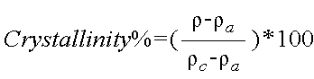
여기서, ρ는 PET 물질의 밀도이고, ρa는 순수한 비정질 PET 물질(1.333 g/cc)이며, ρc는 순수 결정화된(crystalline) 물질(1.455 g/cc)이다.Where ρ is the density of the PET material, ρ a is the pure amorphous PET material (1.333 g / cc), and ρ c is the pure crystalline material (1.455 g / cc).
PET 용기의 결정도는 기계적인 공정과 열 공정에 의하여 중가될 수 있다. 기계적인 공정은 인장 경화(strain hardening)를 달성하기 위하여 비정질 물질로 순응시키는 단계를 포함한다. 이 공정은 공통적으로 길이방향 축을 따라 PET의 초기형태로 늘리는 단계와 PET 용기를 형성하기 위하여 횡 또는 반경방향 축을 따라서 PET의 초기형태로 팽창하는 단계를 포함한다. 조합은 용기의 분자 구조의 양축 지향(biaxial orientation)이라고 알려진 것을 촉진한다. PET 용기의 제조업자들은 용기 측벽의 결정도를 20% 정도 가지는 PET 용기를 생산하기 위하여 현재 기계적인 공정을 사용한다.The crystallinity of PET containers can be increased by mechanical and thermal processes. The mechanical process includes the step of acclimatizing with an amorphous material to achieve strain hardening. This process commonly includes stretching to the initial form of PET along the longitudinal axis and expanding to the initial form of PET along the transverse or radial axis to form the PET container. The combination facilitates what is known as the biaxial orientation of the molecular structure of the vessel. Manufacturers of PET containers currently use mechanical processes to produce PET containers with a 20% crystallinity of the container sidewalls.
열 공정은 크리스탈 성장을 촉진하기 위하여 비정질 또는 반 결정화된 것 중의 하나인 물질을 가열하는 단계를 포함한다. 비정질 물질에서, PET 물질의 열 공정은 광의 투과를 구과(球顆) 형태(spherulitic morphology)를 초래한다. 다시 말하면, 결과적인 결정화된 물질은 불투명하고, 따라서 일반적으로 바람직하지 않다. 그러나, 기계적인 공정 이후에 사용되면, 양축 분자 지향을 가지는 용기의 그 부분들에 대해서 열 공정은 더 높은 결정도와 뛰어난 투명도를 초래한다. 열 경화라고 알려진 지향된 PET 용기의 열 공정은 통상적으로 약 120℃-l3O℃의 온도로 가열된 주형(mold)에 대하여 PET 초기형태로 블로우 몰딩하는 단계와 약 3초동안 가열된 주형에 대하여 블로우된 용기를 유지하는 단계를 포함한다. 약 85℃에서 고온으로 채워져야 하는 PET 쥬스 병의 제조업자들은 25-30%범위의 전체 결정도를 가지는 PET 병들을 생산하기 위하여 현재 열 경화를 사용한다.The thermal process includes heating a material that is either amorphous or semi-crystallized to promote crystal growth. In amorphous materials, thermal processing of PET materials results in spherulitic morphology of the transmission of light. In other words, the resulting crystallized material is opaque and therefore generally undesirable. However, if used after a mechanical process, the thermal process results in higher crystallinity and excellent transparency for those parts of the container having biaxial molecular orientation. The thermal process of a directed PET container known as thermal curing typically involves blow molding into a PET initial form on a mold heated to a temperature of about 120 ° C. −30 ° C. and blow on a mold heated for about 3 seconds. Maintaining the finished container. Manufacturers of PET juice bottles, which must be filled at high temperatures at about 85 ° C., currently use thermal curing to produce PET bottles with a total crystallinity in the range of 25-30%.
고온으로 채워진 뒤, 열 경화 용기들은 마개가 씌워지고 대략 5분동안 충전 온도로 잔류된다. 그리고 나서 용기들은 제품과 함께 급속히 냉각되어 충전된 용기는 라벨링, 패키징과 배송 작업으로 이송된다. 냉각되자마자, 용기 내의 액체의 부피는 줄어든다. 이 제품 수축 현상은 용기내의 진공 생성을 초래한다. 일반적으로 용기 내의 진공압은 1-300mm/Hg 범위이다. 이런 진공압이 제어되지 못하거나 수용되지 못하면, 이런 진공압은 용기의 변형을 초래하게 되어 미적으로 받아들여질 수 없는 용기가 되거나 불안정한 용기가 되게 만든다. 전형적으로, 진공압은 용기의 측벽의 구조를 포함함으로써 조절되어 왔다. 이런 구조들은 진공 패널이라고 공통적으로 알려져 있다. 진공 패널들은 용기 측벽의 원하지 않는 변형을 제거하기 위하여 제어된 방식으로 진공압하에서 안쪽으로 찌그러지도록 설계된다.After filling at high temperature, the thermosetting containers are capped and left to fill temperature for approximately 5 minutes. The containers are then rapidly cooled with the product and the filled containers are transported for labeling, packaging and shipping operations. As soon as it cools down, the volume of liquid in the container decreases. This product shrinkage results in the creation of a vacuum in the container. Generally the vacuum pressure in the vessel is in the range of 1-300 mm / Hg. If this vacuum pressure is uncontrolled or unacceptable, it will cause the container to deform, resulting in an aesthetically unacceptable container or an unstable container. Typically, the vacuum pressure has been adjusted by including the structure of the side wall of the container. These structures are commonly known as vacuum panels. The vacuum panels are designed to distort inward under vacuum pressure in a controlled manner to remove unwanted deformation of the container sidewalls.
진공 패널이 용기가 고온 충전 과정의 엄격함을 지탱하도록 허용하는 반면, 그것들은 몇가지 제한과 단점을 제공한다. 첫째, 매끄러운 유리같은 외관이 달성될 수 없다. 둘째, 라벨링 동안, 감기는 랩 또는 슬리브 라벨이 진공 패널위로 용기에 부착된다. 가끔, 측벽과 진공 패널에 있는 이러한 라벨의 외관이 그러하여 라벨이 주름지거나 매끄럽게 되지 못한다. 뿐만 아니라, 용기를 잡을 때, 진공 패 널의 다양한 균열과 요부로 밀리는 라벨을 초래하여 진공 패널이 라벨의 아래에서 느껴지게 된다.While the vacuum panel allows the vessel to withstand the rigors of the hot filling process, they present some limitations and disadvantages. First, a smooth glassy appearance cannot be achieved. Second, during labeling, a wrap wrap or sleeve label is attached to the container over the vacuum panel. Occasionally, the appearance of these labels on the sidewalls and the vacuum panel thus prevents the labels from wrinkling or smoothing. In addition, when holding the container, the vacuum panel is felt under the label, causing various cracks and recesses in the vacuum panel.
뿐만 아니라 진공압으로부터 초래되는 용기의 변형을 조절하는 것을 돕기 위하여 섬세한 개선은 용기 측벽에 핀치 그립 기하구조(pinch grip geometry)의 사용을 하도록 하여 왔다. 그러나, 진공 패널에 관하여 핀치 그립 기하구조를 사용하는 것에도 유사한 제한과 단점이 존재한다.In addition, minor improvements have been made to the use of pinch grip geometry on the container sidewalls to help control the deformation of the vessel resulting from vacuum pressure. However, similar limitations and disadvantages exist with the use of pinch grip geometries with respect to vacuum panels.
고온 충전 플라스틱 용기가 진공을 수용하는 구조적 특징을 갖지 않고도 상기 목적을 달성하기 위한 또 다른 방법은 질소 주입 기술의 사용이다. Another way to achieve this object without the high temperature filled plastic container having structural features to receive a vacuum is the use of nitrogen injection techniques.
그러나 이 기술을 사용할 때의 한가지 단점은 현재의 기술로 이룰 수 있는 최소한의 라인 속도는 분당 대략 200개의 용기에 제한된다는 점이다. 그 정도의 느린 라인 속도는 거의 허용될 수 없다. 뿐만 아니라, 주입의 일관성은 효율적인 작업을 이루기 위한 기술적인 수준에 도달하지 못하고 있다.
따라서, 매끄럽고 유리와 같은 외관을 가질 수 있도록 실질적인 기하구조없이 측벽을 가지는 유리 용기의 외관을 흉내내는 고온의 충전에서 초래되는 진공압을 수용할 수 있는 개선된 용기의 필요성이 존재한다. 따라서, 발명의 목적은 그러한 용기를 제공하는 것이다.However, one disadvantage of using this technique is that the minimum line speed achievable with current technology is limited to approximately 200 vessels per minute. That slow line speed is hardly acceptable. In addition, the consistency of injection has not reached the technical level to achieve efficient work.
Accordingly, there is a need for an improved container capable of accommodating vacuum pressure resulting from high temperature filling that mimics the appearance of a glass container having a sidewall without a substantial geometry so that it can have a smooth, glassy appearance. Therefore, it is an object of the invention to provide such a container.
삭제delete
따라서, 본 발명은 고온 충전되고 주위 온도로 냉각된 이후의 어떤 후속의 취급 동안에 심미감과 기계적인 일체성을 유지하는 플라스틱 용기를 제공하며, 이는 용기의 다른 부분에서 원하지 않는 변형없이 베이스에 의해 진공압의 실질적인 흡수를 허용하는 베이스 구조를 가짐으로써 달성가능하다. Thus, the present invention provides a plastic container that maintains aesthetics and mechanical integrity during any subsequent handling after being hot charged and cooled to ambient temperature, which is vacuum pressured by the base without unwanted deformation in other parts of the container. It is achievable by having a base structure that allows substantial absorption of.
유리 용기에서, 용기는 움직이지 않고, 그 구조는 모든 압력과 힘들을 제한해야 한다. 가방 용기에서 용기는 쉽게 이동하고 제품에 맞게 순응한다. 본 발명은 다소 세련된 것으로, 움긱이는 영역과 움직이지 않는 영역을 제공한다. 궁극적으로, 본 발명의 플라스틱 용기의 베이스부가 움직이고 변형된 후에, 용기의 나머지 전체 구조는 부서지지 않고도 모든 추가적인 압력이 힘들을 제한한다.In glass containers, the container does not move, and its structure must limit all pressures and forces. In the bag container, the container is easily moved and adapted to the product. The present invention is somewhat refined, providing a convex and non-moving region. Ultimately, after the base portion of the plastic container of the present invention is moved and deformed, all further pressure limits the force without breaking the rest of the overall structure of the container.
본 발명은 상부, 본체부 또는 측벽부 및 베이스를 가지는 플라스틱 용기를 포한한다. 상부는, 포함하도록 요구되는 것은 아니지만, 용기의 주둥이를 정의하는 개구, 마침부(finish section), 나사산 영역 및 지지 링을 포함한다. 본체부는 상부에서 베이스까지 연장된다. 베이스는 중앙 푸쉬업(pushup)과 반전 링에 의하여 적어도 부분적으로 정의되는 중앙부를 포함한다. 중앙 푸쉬업과 반전 링은 용기에서 발생된 진공력을 수용하도록 이동 가능하다.The present invention encompasses a plastic container having a top, a body portion or a side wall portion and a base. The top includes, but is not required to include, an opening that defines the spout of the container, a finish section, a threaded region and a support ring. The body portion extends from the top to the base. The base includes a central portion defined at least in part by a central pushup and a reversal ring. The central push up and inversion ring are movable to accommodate the vacuum force generated in the vessel.
본 발명의 추가적인 이익과 장점은 이하 설명하는 바람직한 실시예와 추가된 청구항을 첨부된 도면과 함께 고려하는 것으로부터 본 발명이 속하는 기술분야에서 통상의 지식을 가진자에게 명백해질 것이다. Further advantages and advantages of the present invention will become apparent to those skilled in the art from consideration of the preferred embodiments described below and the appended claims in conjunction with the accompanying drawings.
도 1은 본 발명에 따른 플라스틱 용기의 측면도로서, 용기는 몰딩되고 비어 있는 상태이다.1 is a side view of a plastic container according to the present invention, in which the container is molded and empty.
도 2는 본 발명에 따른 플라스틱 용기의 측면도로서, 용기는 채워지고 시일링된 상태이다.Figure 2 is a side view of a plastic container according to the present invention in which the container is filled and sealed.
도 3은 도 1의 플라스틱 용기의 바닥 부분의 사시도이다.3 is a perspective view of a bottom portion of the plastic container of FIG. 1.
도 4는 도 2의 플라스틱 용기의 바닥 부분의 사시도이다.4 is a perspective view of a bottom portion of the plastic container of FIG. 2.
도 5는 도 3의 5-5라인을 따라 절취하였을 때의 플라스틱 용기의 단면도이다.5 is a cross-sectional view of the plastic container when taken along line 5-5 of FIG.
도 6은 도 4의 6-6라인을 따라 절취하였을 때의 플라스틱 용기의 단면도이다.6 is a cross-sectional view of the plastic container when taken along line 6-6 of FIG.
바람직한 실시예의 다음 기술은 본질적으로 단지 예시에 불과한 것이며, 결코 발명 또는 그 적용이나 용도를 제한하려는 것은 아니다.The following description of the preferred embodiments is merely exemplary in nature and is in no way intended to limit the invention or its application or use.
상기 기술된 바와 같이, 열 경화 용기내에서 내용물의 냉각 동안에 진공력을 수용하기 위하여 용기는 그 측벽 주위에 일련의 진공 패널 또는 핀치 그립들이 제공되어 왔다. 진공 패널과 핀치 그립은 진공력의 영향하에 내측으로 변형되고 용기의 원하지 않는 다른 부분의 변형을 방지한다. 그러나, 진공 패널과 핀치 그립을 사용함으로써 용기 측벽은 매끄럽거나 유리와 같지 못하고, 겹쳐지는 라벨은 매끄럽지 못하며 최종 수요자는 용기를 잡고 집어 올릴 때 진공 패널과 핀치 그립을 느끼게 된다.As described above, the container has been provided with a series of vacuum panels or pinch grips around its sidewalls to accommodate vacuum forces during cooling of the contents in the thermosetting container. The vacuum panel and pinch grip deform inwards under the influence of vacuum force and prevent deformation of other undesired portions of the container. However, by using a vacuum panel and pinch grips, the container sidewalls are not smooth or glassy, the overlapping labels are not smooth and the end consumer feels the vacuum panel and pinch grips when picking up the container.
진공 패널 없는 용기에서 용기의 잔류물내에서의 조절된 변형(예를 들면, 베이스 또는 닫힘부에서)과 진공 저항이 요구된다. 따라서, 본 발명은 용기의 잔류물내에서의 강성 구조(예를 들면, 내부 진공에 대항하는)를 유지하면서 베이스부를 쉽게 움직이고 변형되도록 하는 플라스틱 용기를 제공한다. 예를 들면, 20온스(oz.)(0.00059m3)의 플라스틱 용기에서, 용기는 대략 22cc(22㎖)의 부피 변화를 수용할 수 있어야 한다. 본 발명의 플라스틱 용기에서, 베이스부는 이러한 요구조건(예를 들면, 대략 18.5cc(18.5㎖))의 대다수를 수용한다. 플라스틱 용기의 나머지 부분은 이 부피 변화의 나머지를 쉽게 수용할 수 있다.In a vessel without a vacuum panel, a controlled deformation (eg, at the base or the closure) and the vacuum resistance in the residue of the vessel are required. Accordingly, the present invention provides a plastic container that allows the base portion to be easily moved and deformed while maintaining a rigid structure (eg, against internal vacuum) within the residue of the container. For example, in a 20 oz. (0.00059 m 3 ) plastic container, the container should be able to accommodate a volume change of approximately 22 cc (22 ml). In the plastic container of the present invention, the base portion accommodates the majority of these requirements (eg, approximately 18.5 cc (18.5 ml)). The rest of the plastic container can easily accommodate the rest of this volume change.
도 1 및 도 2에 도시된 바와 같이, 본 발명의 플라스틱 용기(10)는 마침부(12), 연장된 목(14), 어깨 영역(shoulder region, 16), 본체부(18) 및 베이스(20)를 포함한다. 플라스틱 용기(10)는 특히 고온 파스퇴르화 또는 리토르트와 같은 열 공정 동안에 물품을 보관하기 위하여 설계되었다.As shown in FIGS. 1 and 2, the
본 발명의 플라스틱 용기(10)는 블로우 몰딩 되고, PET 수지(polyethylene terephthalate resin)와 같은 단층 또는 다층 물질로부터 단일 구조를 가진 단일 양축으로 지향된 용기이다. 대신에, 플라스틱 용기(10)는 다른 방법으로 형성될 수도 있고, 예를 들면, PEN(polyethylene napthalate)와 PET/PEN 혼합 또는 공중합체(copolymer)를 포함하는 종래의 다른 물질로부터 형성될 수도 있다. PET 물질로부터 단일 구조를 가지고 블로우 몰딩된 플라스틱 용기는 플라스틱 용기의 기술분야에서 알려지고 사용되고 있으며, 기술분야에 속하는 통상의 지식을 가진 자에 의하여 쉽게 이해될 수 있다.The
플라스틱 용기(10)의 마침부(12)는 개구 또는 주둥이(22)를 한정하는 부분, 나사산 영역(24)과 지지 링(26)을 포함한다. 개구(22)는 나사산 영역(24)이 유사하게 나사산이 형성된 마개 또는 캡(28)의 부착을 위한 수단을 제공하는 동안 플라스틱 용기(10)가 물품을 수용할 수 있도록 해준다.(도 2) 대체물은 플라스틱 용기 (10)의 마침부(12)를 맞물리게 하는 다른 적당한 장치를 포함할 수 있다. 따라서, 마개 또는 캡(28)은 바람직하게 플라스틱 용기(10)에 밀폐를 제공하기 위하여 마침부(12)와 맞물리게 하는 역할을 한다.The
마개 또는 캡(28)은 바람직하게는 고온의 파스퇴르화 또는 리토르트를 포함하여 후속하는 열공정에 적합하고 마개 산업에 전통적인 플라스틱 또는 금속 물질로 만들어진다. 지지 링(26)은 제조의 여러 단계들 및 그것을 통하여 예형태(preform)(플라스틱 용기(10)의 전구체)를 운반하고 그 위치를 잡게하는 데 사용될 수 있다. 예를 들면, 예형태는 지지 링(26)에 의하여 이동될 수 있고, 지지 링(26)은 주형에서 예형태를 위치시키는 것을 돕는 데 사용되거나 최종 수요자들이 플라스틱 용기(10)를 이동시키는 데 사용될 수 있다.The stopper or
플라스틱 용기(10)의 목(14)은 연장되어 있어서 플라스틱 용기(10)가 부피 요구를 수용할 수 있게 해 준다. 어깨 영역(16)은 연장된 목(14)과 일체로 형성되며 연장된 목으로부터 아래방향으로 연장된다. 어깨 영역(16)은 합쳐지고 연장된 목(14)과 본체부(18) 사이에서의 전이(transition)를 제공한다. 본체부(18)는 어깨 영역(16)으로부터 베이스(20)까지 아래로 연장되며, 측벽(30)을 포함한다. 용기(10) 베이스(20)의 특정한 구조로 인하여, 열 경화된 용기(10)의 측벽(30)은 진공 패널 또는 핀치 그립의 내에 포함되지 않고 형성되며, 전체적으로 매끄럽고 유리와 같다. 상당히 가벼운 용기는 베이스(20)를 따라 진공 패널 및/또는 핀치 그립을 갖는 측벽을 포함함으로써 형성될 수 있다.The
플라스틱 용기(10)의 베이스(20)는 전체적으로 본체부(18)로부터 연장되며, 일반적으로 돌출 가장자리(chime, 32), 접촉 링(34) 및 중앙부(36)를 포함한다. 도 5 및 도 6에 도시된 바와 같이, 접촉 링(34)은 용기(10)가 지지되는 지지 표면(38)을 접촉하는 베이스(20) 그 자체이다. 그러한 것으로서, 접촉 링(34)은 베이스(20)를 연속적으로 또는 간헐적으로 둘러싸는 접촉 선 또는 평면일 수 있다. 베이스(20)는 연장된 목(14), 어깨 영역(16) 및 본체부(18)과 함께 물품을 보관하기 위하여 플라스틱 용기(10)의 바닥부를 닫는 역할을 한다.The
플라스틱 용기(10)는 상기 언급된 공정 또는 다른 전통적인 열 경화 공정에 따라 바람직하게 열 경화된다. 용기(10)의 본체부(18)에서 진공 패널과 핀치 그립을 없앨 수 있도록 하고 진공력을 수용하기 위하여 본 발명의 베이스(20)는 새롭고 진보성있는 구조를 채택한다. 일반적으로, 베이스(20)의 중앙부(36)에는 중앙 푸쉬업(pushup, 40)과 반전 링(42)이 제공된다. 또한, 베이스(20)는 반전 링(42)과 접촉 링(34)사이의 천이를 형성하는 원주방향으로 직립하는 벽(44)을 포함한다.The
도 1 내지 도 6에 도시된 바와 같이, 중앙 푸쉬업(40)은, 단면으로 보았을 때, 지지 표면(38)에 실질적으로 평행한 꼭대기 면(46)과 용기(10) 중앙의 길이방향 축에 대하여 상향하도록 기울어진 평면인 측 평면(48)을 갖는 원뿔대 형상으로 전체적으로 되어 있다. 중앙 푸쉬업(40)의 정확한 형상은 다양한 설계 기준에 따라서 크게 변화될 수 있다. 그러나, 대체로, 중앙 푸쉬업(40)의 직경은 베이스(20)의 전체 직경의 최대 30%이다. 중앙 푸쉬업(40)은 전체적으로 예형태의 게이트가 주형에서 포획되는 부분이고, 실질적으로 지향되지 않은 용기(10)의 베이스(20)이다.As shown in FIGS. 1-6, the central push-
도 3 및 도 5에 도시된 바와 같이, 초기 형성되었을 때, 반전 링(42)은 점진적인 반경을 갖는 중앙 푸쉬업(40)을 완전히 둘러싸는 링으로 몰딩된다. 형성될 때, 반전 링(42)은 평평하다면 놓여질 평면의 하부에 외측으로 돌출된다. 단면도에서 볼 때(도 5 참고), 반전 링(42)은 전체적으로 "S"자 형태이다. 중앙 푸쉬업(40)과 인접한 반전 링(42) 사이의 천이는 가능하면 중앙 푸쉬업(40) 근처로 많이 지향되는 것을 촉진하기 위하여 신속해야 한다. 이것은 베이스(20)의 반전 링(42)의 최소 벽 두께를 일차적으로 보장한다. 전형적으로, 반전 링(42)의 벽 두께는 대략 0.203mm에서 약 0.635mm사이이다. 반전 링(42)의 벽 두께는 반전 링(42)이 유연하고 적절히 작용할 수 있도록 충분히 얇아야 한다. 그 우회 형상을 따라 어떤 지점에서, 이와는 달리 반전 링(42)은, 도시되지는 않았지만 기술분야에서 잘 알려진 것으로써 라벨을 붙이는 작업중에 중앙의 길이방향 축(50)에 대한 용기의 회전을 용이하게 하는 폴(pawl)을 수용하는데 적합한 작은 움푹 들어간 부분(indentation)을 특징으로 할 수 있다.As shown in FIGS. 3 and 5, when initially formed, the
원주방향으로 직립하는 벽(44)은 접촉 링(34)과 반전 링(42) 사이의 천이를 한정하며, 69.85mm의 직경을 갖는 베이스 용기의 경우 대략 0.762mm에서 약 4.572mm까지의 높이를 가지며, 127mm의 직경을 갖는 베이스 용기의 경우 대략 1.27mm에서 약 8.255mm의 높이 또는 그와 유사한 비율의 높이를 갖는 직립 벽이며, 용기(10)의 중앙의 길이방향 축(50)에 평행한 것처럼 전체적으로 보여진다. 원주방향으로 직립하는 벽(44)은 중앙의 길이방향 축(50)에 정확히 평행할 필요는 없는 반면, 원주방향으로 직립하는 벽(44)은 접촉 링(34)과 반전 링(42) 사이에서 별개로 식별될 수 있는 구조라는 것이 인식되어야 한다. 원주방향으로 직립하는 벽(44)은 접촉 링(34)와 반전 링(42) 사이의 천이에 강도를 제공한다. 이 천이는 기하학적으로 강성 구조를 형성하기 위해서일 뿐만 아니라 국부 강도를 최대화하기 위하여 급격히 이루어져야 한다. 결과적인 국부화된 강도는 막음(ceasing)에 대한 저항을 증가시킨다.The circumferentially
중앙 푸쉬업(40)과 반전 링(42)이 초기에 형성되면, 도 1, 도 3 및 도 5에 도시되고 상기 기술된 바와 같이 남는다. 따라서, 몰딩된 바대로, 반전 링(42)의 제 1 부분(54)과 지지 표면(38) 사이에 측정된 치수(52)는 반전 링(42)의 제 2 부부분(58)과 지지 표면(38) 사이에 측정된 치수(56)보다 크거나 같다. 일단 채워지면, 베이스(20)의 중앙부(36)와 반전 링(42)은 물품의 온도와 무게로 인해 약간 가라앉고 지지 표면(38)에 대하여 아랫방향으로 구부러질 것이다. 그 결과, 치수(56)은 거의 0이 되는데, 즉, 반전 링(42)의 제 2 부분(58)은 실제적으로 지지 표면(38)과 접촉하게 된다. 마개가 씌워지고, 시일링 되고 냉각되면, 도 2, 도 4 및 도 6에 도시된 바와 같이, 중앙 푸쉬업(40)과 반전 링(42)은 들어올려지고, 진공력에 의한 결과로 부피에 변화가 생긴다. 이 위치에서, 중앙 푸쉬업(40)은 전체적으로 지지 표면(38)에 실질적으로 평행하게 남으면서 중앙 푸쉬업(40)의 꼭대기 면(46)을 가지는 원뿔대의 단면을 유지한다. 그러나, 반전 링(42)은 베이스(20)의 중앙부(36)에 포함되고 가상적으로 없어져서 점점 돔형상부가 되어 간다. 따라서, 용기(10)에 마개가 씌워지고, 시일링 되고 냉각되자 마자, 베이스(20)의 중앙부(36)는 도 6에 도시된 바와 같이 용기(10) 중앙의 길이방향 축(50)에 대하여 전체적으로 경사진 평평한 표면(60)을 갖는 더욱 원추형상의 돔형상부를 보여준다. 이 돔형상부와 전체적으로 평평한 표면(60)은 수직 평면과 지지 표면(38)에 대하여 약 0°에서 약 15°의 각도(62)로서 한정될 수 있다. 치수(52)가 더 커지고, 치수(56)이 더 작아질수록, 달성가능한 부피의 변화는 커진다.Once the central push-
베이스(20)의 중앙부(36)가 가지는 부피량은 베이스(20)의 투영된 총 표면적과 비교하였을 때 베이스(20)의 중앙부(36)의 투영된 총 표면적에 또한 의존한다. 용기(10)의 본체부(18)에 진공 패널 또는 핀치 그립을 제공할 필요성을 제거하기 위하여, 베이스(20)의 중앙부에는 베이스(20)의 총 투영된 표면적의 약 55%, 바람직하게는 약 70%보다 큰 투영된 표면적이 제공된다. 도 5에 도시된 바와 같이, 베이스(20)를 통과하는 관련된 투영 선의 길이들은 A, B, C1 및 C2로 식별된다. 베이스(20)의 투영된 총 표면적(PSAA)은 다음의 방정식으로 정의된다.The volume amount of the

따라서, 직경 69.85mm의 베이스를 갖는 용기의 경우, 투영된 총 면적(PSAA)는 150.88mm2이다. 베이스(20)의 중앙부(36)의 투영된 총 표면적(PSAB)은 다음의 방정식으로 정의된다.Thus, for a container with a base of 69.85 mm in diameter, the projected total area (PSA A ) is 150.88 mm 2 . The projected total surface area PSA B of the

여기서, B = A-C1-C2이다.Where B = AC 1 -C 2 .
직경이 69.85mm인 베이스를 갖는 용기의 경우, 돌출 가장자리(chime,32)의 길이는 일반적으로 0.762mm부터 9.144mm 범위이다. 따라서, B 치수는 대략 51.56mm부터 68.33mm 범위이다. 그러므로, 베이스(20)의 중앙부(36)의 투영된 표면적(PSAB)는 일반적으로 대략 82.04mm2부터 144.27mm2 범위이다. 따라서, 예를 들어, 69.85mm 직경의 베이스를 갖는 용기에 대한 베이스(20)의 중앙부(36)의 투영된 표면적(PSAB)은 일반적으로 베이스(20)의 투영된 표면적(PSAA)의 대략 54% 에서 96% 범위이다. 이 백분율이 더 커질수록 용기(10)의 다른 면적에서의 원하지 않는 변형없이 용기(10)가 수용할 수 있는 진공의 양은 더 커진다.For containers with a base of 69.85 mm in diameter, the length of the protruding
압력은 진공하에서 플라스틱 용기의 내부에 일정한 방식으로 작용한다. 그러나, 힘은 기하구조(예를 들어, 표면적)에 따라서 다를 것이다. 그러므로, 실린더 단면을 가지는 용기내의 압력은 다음 식으로 정의된다.The pressure acts in a constant manner inside the plastic container under vacuum. However, the force will vary depending on the geometry (eg surface area). Therefore, the pressure in the vessel having the cylinder cross section is defined by the following equation.

여기서, F는 파운드 단위의 힘을 나타내고, A는 제곱 인치단위의 면적을 나타낸다. 도 1에 도시된 바와 같이, 베이스(20)의 중앙부(36)의 직경은 d1으로서 식별된다. 반면, 본체부(18)의 직경은 d2로서 식별된다. 도 1에 연속하여, 어깨 영역(16)에서부터 돌출 가장자리(32)의 꼭대기까지의 본체부(18), 플라스틱 용기(10)의 매끄러운 라벨 패널 영역의 높이는 ℓ로서 식별된다. 위에 제시한 바와 같이, 본체부(18)에서의 추가된 기하구조(예를 들면, 리브(ribs))는 강화 효과를 가질 것이라는 것은 잘 알려져 있다. 아래의 분석은 그러한 기하구조를 가지지 않는 용기의 부분만을 고려한다.Where F is the force in pounds and A is the area in square inches. As shown in FIG. 1, the diameter of the
상기에 따라, 베이스(20)의 중앙부(36)와 관련된 압력(PB)은 다음 방정식에 의하여 정의된다.According to the above, the pressure P B associated with the

여기서, F1은 베이스(20)의 중앙부(36)에 작용하는 힘을 나타내고, A1은 베이스(20)의 중앙부(36)에 관련된 면적으로서

여기서, F2는 본체부(18)에 작용하는 힘을 나타내고, A2는 본체부(18)와 관련된 면적으로서 πd2ℓ이다. 따라서, 베이스(20)의 중앙부(36)에 작용하는 힘과 비교하여 용기(10)의 본체부(18)에 작용하는 힘 사이의 힘 비율은 다음 식에 의하여 정의된다.Here, F 2 represents a force acting on the main body 18, and A 2 is π d 2 L as the area associated with the main body 18. Therefore, the force ratio between the force acting on the body portion 18 of the

최적의 성능을 위하여, 상기 힘 비율은 10이하이어야 하는데, 낮은 비율값이 가장 바람직하다.For optimal performance, the force ratio should be 10 or less, with a lower ratio value being most desirable.
상기 제시한 바와 같이, 용기(10)의 베이스(20)와 본체부(18)사이의 벽 두께 차이는 또한 중요하다. 본체부(18)의 벽 두께는 반전 링(42)이 적절히 굽어질 수 있도록 충분히 커야 한다. 상기 힘 비율이 10에 접근할수록, 용기(10)의 베이스(20)에서의 벽 두께는 본체부(18)의 벽 두께보다 훨씬 작아야 한다. 반전 링(42)을 적절히 굽어질 수 있게 하는데 요구되는 힘의 양과 베이스(20)의 기하구조 즉, 움직임의 난이에 따라서 본체부(18)의 벽 두께는 베이스(20)의 벽 두께보다 평균적으로 최소 15% 커야 한다. 만약 용기가 초기에 반전 링(42)을 구부러지게 하거나 일단 베이스(20)의 움직임이 끝난 후 추가로 가해지는 힘을 수용하는데 요구되는 힘 중 더 큰 어느 하나의 힘을 지탱해야 한다면, 더 큰 차이가 요구된다.As suggested above, the wall thickness difference between the base 20 and the body portion 18 of the
다음의 테이블은 상기 기술한 원리와 개념을 보여주는 수많은 용기들의 예시이다.The following table is an example of a number of containers showing the principles and concepts described above.
크기Vessel
(0.00059m3)(Ⅰ)20 oz
(0.00059m 3 ) (Ⅰ)
(0.00059m3)(Ⅱ)20 oz
(0.00059m 3 ) (Ⅱ)
(0.00059m3)(Ⅲ)20 oz
(0.00059m 3 ) (Ⅲ)
(0.00048m3)16 oz
(0.00048m 3 )
벽 두께(mils)Base (20)
Wall thickness (mils)
22
22
15
15
20
20
20
20
벽 두께(mils)Body part 18
Wall thickness (mils)
26
26
26
26
26
26
32
32
벽 두께는 베이스(20) 벽 두께보다 최소 X(%) 커야 한다.Body part 18
The wall thickness should be at least X (%) greater than the base 20 wall thickness.
38
38
43
43
23
23
16
16
상기 모든 예시적인 예들에서, 용기의 베이스들은 용기의 주요한 변형 메커니즘으로 작용한다. 뿐만 아니라, 힘 비율이 증가할수록, 요구되는 베이스 벽 두께는 감소한다. 게다가, 베이스(20) 벽 두께에 대한 본체부(18)벽 두께의 비교는 힘 비율과 용기의 기하 구조에 부분적으로 의존한다. 비 실린더 단면(예를 들어 "트라운드(tround)" 또는 정사각형)을 갖는 용기에 대한 유사한 분석도 유사한 결과를 가진 것으로 행해질 수 있다.In all of the above illustrative examples, the bases of the vessel serve as the primary deformation mechanism of the vessel. In addition, as the force ratio increases, the required base wall thickness decreases. In addition, the comparison of the body portion 18 wall thickness to the base 20 wall thickness depends in part on the force ratio and the geometry of the container. Similar analyzes for containers with non-cylindrical cross sections (eg, "tround" or square) may be done with similar results.
따라서, 용기(10)의 베이스(20)의 반전 링(42)의 얇고, 유연하고, 곡선의, 전체적으로 "S"자 형상의 기하구조는 실질적으로 평평한 베이스를 갖는 용기에 비하여 더 큰 부피 변화를 갖도록 허용한다.Thus, the thin, flexible, curved, generally "S" shaped geometry of the
대안의 실시예로서, 심미감을 향상시키기 위하여, 가장자리(chime)는 바깥으로 돌출되지 않는다. 그러한 용기에서, 본체부, 가장자리 및 베이스는 함께 더욱 평탄하고 일관되게 흐른다. 그러한 대체 실시예의 용기는 더 전통적인 시각적 인상을 제공한다.As an alternative embodiment, the chime does not protrude outward to enhance the aesthetics. In such containers, the body portion, edges and base flow together more flatly and consistently. The container of such an alternative embodiment provides a more traditional visual impression.
또 다른 대안 실시예로서, 기능성을 향상시키기 위하여 용기는 더욱 두드러지게 돌출된 가장자리(chime)를 포함한다. 진공압하에서, 돌출된 가장자리는 안쪽으로 미세하게 변형되며, 용기의 부피 변화 용량을 추가시키고 더 나아가 용기 베이스의 바깥쪽 에지를 강화시킨다.As another alternative embodiment, the container includes more prominent chimes to enhance functionality. Under vacuum, the protruding edges are finely deformed inward, adding to the volume change capacity of the vessel and further strengthening the outer edge of the vessel base.
상기 기재된 사항은 본 발명의 바람직한 실시예를 구성하지만, 본 발명의 보호범위를 벗어나지 않고 용이하게 수정, 변경 및 변화시킬 수 있다는 것과 본 발명의 진정한 보호범위는 첨부되는 청구항에 의하여 파악되어야 한다는 것이 이해될 것이다.While the above description constitutes a preferred embodiment of the present invention, it is understood that modifications, changes and variations can be made easily without departing from the scope of the present invention and that the true scope of the present invention should be understood by the appended claims. Will be.
본 발명은 물품, 특히 액체 물품을 담는 용기를 제조하는 산업에 이용될 수 있다.The invention can be used in the industry of manufacturing articles, in particular containers containing liquid articles.
Claims (31)
Applications Claiming Priority (3)
| Application Number | Priority Date | Filing Date | Title |
|---|---|---|---|
| US10/445,104 | 2003-05-23 | ||
| US10/445,104 US6942116B2 (en) | 2003-05-23 | 2003-05-23 | Container base structure responsive to vacuum related forces |
| PCT/US2004/013341 WO2004106175A1 (en) | 2003-05-23 | 2004-04-30 | Container base structure responsive to vacuum related forces |
Publications (2)
| Publication Number | Publication Date |
|---|---|
| KR20060031606A KR20060031606A (en) | 2006-04-12 |
| KR101087622B1 true KR101087622B1 (en) | 2011-11-29 |
Family
ID=33450803
Family Applications (1)
| Application Number | Title | Priority Date | Filing Date |
|---|---|---|---|
| KR1020057022425A Expired - Fee Related KR101087622B1 (en) | 2003-05-23 | 2004-04-30 | Base structure of the vessel in response to the force associated with the vacuum |
Country Status (17)
| Country | Link |
|---|---|
| US (1) | US6942116B2 (en) |
| EP (1) | EP1633640B1 (en) |
| JP (3) | JP4884970B2 (en) |
| KR (1) | KR101087622B1 (en) |
| CN (1) | CN100546879C (en) |
| AT (1) | ATE427889T1 (en) |
| AU (1) | AU2004242590B2 (en) |
| BR (1) | BRPI0410631B1 (en) |
| CA (1) | CA2526708C (en) |
| DE (1) | DE602004020467D1 (en) |
| DK (1) | DK1633640T3 (en) |
| ES (1) | ES2322265T3 (en) |
| MX (1) | MXPA05012633A (en) |
| NZ (1) | NZ544001A (en) |
| RU (1) | RU2318710C2 (en) |
| SI (1) | SI1633640T1 (en) |
| WO (1) | WO2004106175A1 (en) |
Families Citing this family (88)
| Publication number | Priority date | Publication date | Assignee | Title |
|---|---|---|---|---|
| US8584879B2 (en) * | 2000-08-31 | 2013-11-19 | Co2Pac Limited | Plastic container having a deep-set invertible base and related methods |
| US7543713B2 (en) | 2001-04-19 | 2009-06-09 | Graham Packaging Company L.P. | Multi-functional base for a plastic, wide-mouth, blow-molded container |
| US7900425B2 (en) | 2005-10-14 | 2011-03-08 | Graham Packaging Company, L.P. | Method for handling a hot-filled container having a moveable portion to reduce a portion of a vacuum created therein |
| US8127955B2 (en) * | 2000-08-31 | 2012-03-06 | John Denner | Container structure for removal of vacuum pressure |
| NZ521694A (en) * | 2002-09-30 | 2005-05-27 | Co2 Pac Ltd | Container structure for removal of vacuum pressure |
| US10435223B2 (en) | 2000-08-31 | 2019-10-08 | Co2Pac Limited | Method of handling a plastic container having a moveable base |
| US10246238B2 (en) | 2000-08-31 | 2019-04-02 | Co2Pac Limited | Plastic container having a deep-set invertible base and related methods |
| US9731884B2 (en) * | 2000-08-31 | 2017-08-15 | Co2Pac Limited | Method for handling a hot-filled plastic bottle having a deep-set invertible base |
| US8381940B2 (en) | 2002-09-30 | 2013-02-26 | Co2 Pac Limited | Pressure reinforced plastic container having a moveable pressure panel and related method of processing a plastic container |
| AU2002257159B2 (en) | 2001-04-19 | 2007-03-01 | Graham Packaging Company, L.P. | Multi-functional base for a plastic wide-mouth, blow-moulded container |
| US9969517B2 (en) | 2002-09-30 | 2018-05-15 | Co2Pac Limited | Systems and methods for handling plastic containers having a deep-set invertible base |
| US6922153B2 (en) * | 2003-05-13 | 2005-07-26 | Credo Technology Corporation | Safety detection and protection system for power tools |
| US8276774B2 (en) * | 2003-05-23 | 2012-10-02 | Amcor Limited | Container base structure responsive to vacuum related forces |
| US7451886B2 (en) * | 2003-05-23 | 2008-11-18 | Amcor Limited | Container base structure responsive to vacuum related forces |
| US9751679B2 (en) | 2003-05-23 | 2017-09-05 | Amcor Limited | Vacuum absorbing bases for hot-fill containers |
| US9394072B2 (en) | 2003-05-23 | 2016-07-19 | Amcor Limited | Hot-fill container |
| US7150372B2 (en) * | 2003-05-23 | 2006-12-19 | Amcor Limited | Container base structure responsive to vacuum related forces |
| NZ569422A (en) * | 2003-07-30 | 2010-02-26 | Graham Packaging Co | Container filling with base projection inverted during transportation, and being pushed up after filling |
| US7287658B1 (en) * | 2004-01-08 | 2007-10-30 | Berry Plastics Corporation | Container having a base with a convex dome and method of use |
| WO2005087628A1 (en) * | 2004-03-11 | 2005-09-22 | Philip Sheets | A process and a device for conveying odd-shaped containers |
| US10611544B2 (en) * | 2004-07-30 | 2020-04-07 | Co2Pac Limited | Method of handling a plastic container having a moveable base |
| US7464825B2 (en) * | 2004-12-01 | 2008-12-16 | Graham Packaging Company, L.P. | Pressure resistant base |
| US20060113274A1 (en) * | 2004-12-01 | 2006-06-01 | Graham Packaging Company, L.P. | Vacuum panel base |
| TWI375641B (en) * | 2004-12-20 | 2012-11-01 | Co2 Pac Ltd | A method of processing a container and base cup structure for removal of vacuum pressure |
| US8075833B2 (en) | 2005-04-15 | 2011-12-13 | Graham Packaging Company L.P. | Method and apparatus for manufacturing blow molded containers |
| US8017065B2 (en) | 2006-04-07 | 2011-09-13 | Graham Packaging Company L.P. | System and method for forming a container having a grip region |
| JP2007030893A (en) * | 2005-07-22 | 2007-02-08 | Yoshino Kogyosho Co Ltd | Synthetic resin bottle |
| US7799264B2 (en) | 2006-03-15 | 2010-09-21 | Graham Packaging Company, L.P. | Container and method for blowmolding a base in a partial vacuum pressure reduction setup |
| JP4725889B2 (en) * | 2006-03-31 | 2011-07-13 | 株式会社吉野工業所 | Synthetic resin housing |
| US9707711B2 (en) | 2006-04-07 | 2017-07-18 | Graham Packaging Company, L.P. | Container having outwardly blown, invertible deep-set grips |
| US8747727B2 (en) | 2006-04-07 | 2014-06-10 | Graham Packaging Company L.P. | Method of forming container |
| GB2443807A (en) * | 2006-11-15 | 2008-05-21 | Plastic Can Company Ltd | Method and apparatus for making a container with a pressure accommodating base |
| US7757874B2 (en) * | 2007-01-18 | 2010-07-20 | Ball Corporation | Flex surface for hot-fillable bottle |
| US11897656B2 (en) | 2007-02-09 | 2024-02-13 | Co2Pac Limited | Plastic container having a movable base |
| US11731823B2 (en) | 2007-02-09 | 2023-08-22 | Co2Pac Limited | Method of handling a plastic container having a moveable base |
| RU2449943C2 (en) * | 2007-03-31 | 2012-05-10 | Айзапак Холдинг С.А. | Method of filling shrinkable container |
| FR2919579B1 (en) * | 2007-07-30 | 2011-06-17 | Sidel Participations | CONTAINER COMPRISING A BACKGROUND WITH A DEFORMABLE MEMBRANE. |
| JP2009090995A (en) * | 2007-10-05 | 2009-04-30 | Asahi Breweries Ltd | Containerized beverage and its manufacturing method |
| FR2926034B1 (en) * | 2008-01-08 | 2010-01-22 | Sidel Participations | MOLD BOTTOM FOR MOLD FOR MANUFACTURING THERMOPLASTIC CONTAINERS, AND MOLDING DEVICE EQUIPPED WITH AT LEAST ONE MOLD PROVIDED WITH SUCH A BOTTOM. |
| AU2013206495B2 (en) * | 2008-03-27 | 2016-07-07 | Plastipak Packaging, Inc. | Container base having volume absorption panel |
| MX2010010578A (en) | 2008-03-27 | 2011-05-02 | Constar Int Inc | Container base having volume absorption panel. |
| US8627944B2 (en) | 2008-07-23 | 2014-01-14 | Graham Packaging Company L.P. | System, apparatus, and method for conveying a plurality of containers |
| CA2943758C (en) * | 2008-11-27 | 2019-04-09 | Yoshino Kogyosho Co., Ltd. | Synthetic resin bottle |
| US8047388B2 (en) * | 2008-12-08 | 2011-11-01 | Graham Packaging Company, L.P. | Plastic container having a deep-inset base |
| US8636944B2 (en) * | 2008-12-08 | 2014-01-28 | Graham Packaging Company L.P. | Method of making plastic container having a deep-inset base |
| JP2012513943A (en) * | 2008-12-31 | 2012-06-21 | プラスチパック パッケージング,インコーポレイテッド | High temperature fillable plastic container with flexible base |
| US20130213980A1 (en) * | 2008-12-31 | 2013-08-22 | Plastipak Packaging, Inc. | Plastic container with flexible base |
| US7926243B2 (en) | 2009-01-06 | 2011-04-19 | Graham Packaging Company, L.P. | Method and system for handling containers |
| CA2768822C (en) * | 2009-07-31 | 2017-10-17 | Amcor Limited | Hot-fill container |
| US20110049083A1 (en) * | 2009-09-01 | 2011-03-03 | Scott Anthony J | Base for pressurized bottles |
| US8444002B2 (en) | 2010-02-19 | 2013-05-21 | Graham Packaging Lc, L.P. | Pressure compensating bases for polymeric containers |
| CN102958673B (en) * | 2010-06-28 | 2015-10-14 | 日精Asb机械株式会社 | The manufacture method of heatproof container |
| JP5501184B2 (en) * | 2010-09-30 | 2014-05-21 | 株式会社吉野工業所 | Bottle |
| JP2012076747A (en) * | 2010-09-30 | 2012-04-19 | Yoshino Kogyosho Co Ltd | Bottle |
| US9085387B2 (en) * | 2010-09-30 | 2015-07-21 | Yoshino Kogyosho Co., Ltd. | Synthetic resin bottle |
| CN103180213B (en) * | 2010-10-26 | 2015-02-11 | 株式会社吉野工业所 | bottle |
| JP5684534B2 (en) * | 2010-10-26 | 2015-03-11 | 株式会社吉野工業所 | Bottle |
| US8962114B2 (en) | 2010-10-30 | 2015-02-24 | Graham Packaging Company, L.P. | Compression molded preform for forming invertible base hot-fill container, and systems and methods thereof |
| US9133006B2 (en) | 2010-10-31 | 2015-09-15 | Graham Packaging Company, L.P. | Systems, methods, and apparatuses for cooling hot-filled containers |
| US8991628B2 (en) | 2010-11-12 | 2015-03-31 | Graham Packaging Company, L.P. | Hot-fill jar base |
| USD650677S1 (en) | 2010-11-12 | 2011-12-20 | Graham Packaging Company, L.P. | Container base |
| DE102010064125A1 (en) * | 2010-12-23 | 2012-06-28 | Krones Aktiengesellschaft | Container made of a thermoplastic material |
| CA2831066C (en) | 2011-03-24 | 2019-09-10 | Ring Container Technologies | Flexible panel to offset pressure differential |
| US9994378B2 (en) | 2011-08-15 | 2018-06-12 | Graham Packaging Company, L.P. | Plastic containers, base configurations for plastic containers, and systems, methods, and base molds thereof |
| US9150320B2 (en) | 2011-08-15 | 2015-10-06 | Graham Packaging Company, L.P. | Plastic containers having base configurations with up-stand walls having a plurality of rings, and systems, methods, and base molds thereof |
| US8919587B2 (en) | 2011-10-03 | 2014-12-30 | Graham Packaging Company, L.P. | Plastic container with angular vacuum panel and method of same |
| WO2013073261A1 (en) | 2011-11-18 | 2013-05-23 | 東洋製罐株式会社 | Container consisting of synthetic resin |
| JP2013154907A (en) * | 2012-01-30 | 2013-08-15 | Yoshino Kogyosho Co Ltd | Bottle |
| JP6224300B2 (en) * | 2012-01-30 | 2017-11-01 | 株式会社吉野工業所 | Bottle |
| EP2698320B1 (en) | 2012-08-16 | 2017-07-19 | Plastipak BAWT S.à.r.l. | Hot-fillable plastic container having vertical pillars and concave deformable sidewall panels |
| US9254937B2 (en) | 2013-03-15 | 2016-02-09 | Graham Packaging Company, L.P. | Deep grip mechanism for blow mold and related methods and bottles |
| US9022776B2 (en) | 2013-03-15 | 2015-05-05 | Graham Packaging Company, L.P. | Deep grip mechanism within blow mold hanger and related methods and bottles |
| FR3012115B1 (en) * | 2013-10-23 | 2015-12-11 | Sidel Participations | CONTAINER WITH AN EVOLUTIVE SECTION BETWEEN A SQUARE CONTOUR AND A RECTANGULAR CONTOUR |
| EP2905119A1 (en) | 2014-02-07 | 2015-08-12 | Appe Benelux | System and process for double-blow molding a heat resistant and biaxially stretched plastic container |
| PT3140205T (en) | 2014-05-07 | 2024-09-19 | Milacron Llc | PLASTIC CONTAINER WITH FLEXIBLE BASE PART |
| PL3145822T3 (en) | 2014-05-23 | 2022-04-19 | Plastipak Bawt S.À.R.L. | Heat resistant and biaxially stretched blow-molded plastic container having a base movable to accommodate internal vacuum forces and issued from a double-blow process |
| ES2625441T3 (en) | 2014-08-12 | 2017-07-19 | Plastipak Bawt S.À.R.L. | Vent closure for a container and process for filling and sealing a container |
| MX378570B (en) * | 2014-08-21 | 2025-03-11 | Amcor Rigid Plastics Usa Llc | VESSEL BASE INCLUDING HEMISPHERIC DRIVE DIAPHRAGM. |
| EP3109176A1 (en) * | 2015-06-23 | 2016-12-28 | Sidel Participations | Container provided with a curved invertible diaphragm |
| JP2017178381A (en) * | 2016-03-30 | 2017-10-05 | 株式会社吉野工業所 | Synthetic resin bottle |
| JP6942842B2 (en) * | 2016-03-30 | 2021-09-29 | 株式会社吉野工業所 | Synthetic resin bottle |
| USD804310S1 (en) * | 2016-11-30 | 2017-12-05 | Mohamed Farid Nakkouri | Bottle |
| CA2999296C (en) * | 2017-03-27 | 2025-09-23 | Yoshino Kogyosho Co., Ltd. | Pressure reduction-absorbing bottle |
| MX2020003252A (en) * | 2017-09-21 | 2020-09-18 | Amcor Rigid Packaging Usa Llc | Method of inverting container base prior to cooling. |
| JP7151139B2 (en) * | 2018-04-09 | 2022-10-12 | 東洋製罐グループホールディングス株式会社 | Polylactic acid container and manufacturing method thereof |
| MX2021008543A (en) | 2019-01-15 | 2021-08-19 | Amcor Rigid Packaging Usa Llc | Vertical displacement container base. |
| ES2962408T3 (en) | 2019-01-29 | 2024-03-18 | Amcor Rigid Packaging Usa Llc | Vertical displacement devices and methods for mechanically inverting a thermoplastic container base |
| US11970324B2 (en) | 2022-06-06 | 2024-04-30 | Envases USA, Inc. | Base of a plastic container |
Citations (2)
| Publication number | Priority date | Publication date | Assignee | Title |
|---|---|---|---|---|
| US20020074336A1 (en) | 2000-07-24 | 2002-06-20 | Silvers Kerry W. | Container base structure |
| WO2002085755A1 (en) | 2001-04-19 | 2002-10-31 | Graham Packaging Company, L.P. | Multi-functional base for a plastic wide-mouth, blow-molded container |
Family Cites Families (26)
| Publication number | Priority date | Publication date | Assignee | Title |
|---|---|---|---|---|
| US3409167A (en) * | 1967-03-24 | 1968-11-05 | American Can Co | Container with flexible bottom |
| US3942673A (en) * | 1974-05-10 | 1976-03-09 | National Can Corporation | Wall construction for containers |
| JPS5325186A (en) * | 1976-08-20 | 1978-03-08 | Daiwa Can Co Ltd | Metallic can for drink containing carbon dioxide or the like |
| US4125632A (en) * | 1976-11-22 | 1978-11-14 | American Can Company | Container |
| FR2379443A1 (en) | 1977-02-04 | 1978-09-01 | Solvay | HOLLOW BODY IN THERMOPLASTIC MATERIAL |
| FR2408524A1 (en) * | 1977-11-10 | 1979-06-08 | Solvay | HOLLOW BODY IN ORIENTED THERMOPLASTIC MATERIAL |
| GB2034663B (en) * | 1978-11-07 | 1983-09-01 | Yoshino Kogyosho Co Ltd | Synthetic resin thin-walled bottle |
| US4406698A (en) * | 1980-04-28 | 1983-09-27 | Tokyo Shibaura Denki Kabushiki Kaisha | Martensitic stainless cast steel having high cavitation erosion resistance |
| US4342398A (en) * | 1980-10-16 | 1982-08-03 | Owens-Illinois, Inc. | Self-supporting plastic container for liquids |
| US4408698A (en) | 1980-11-24 | 1983-10-11 | Ballester Jose F | Novel cover and container assembly |
| US4381061A (en) | 1981-05-26 | 1983-04-26 | Ball Corporation | Non-paneling container |
| US4667454A (en) | 1982-01-05 | 1987-05-26 | American Can Company | Method of obtaining acceptable configuration of a plastic container after thermal food sterilization process |
| US4880129A (en) * | 1983-01-05 | 1989-11-14 | American National Can Company | Method of obtaining acceptable configuration of a plastic container after thermal food sterilization process |
| US4642968A (en) * | 1983-01-05 | 1987-02-17 | American Can Company | Method of obtaining acceptable configuration of a plastic container after thermal food sterilization process |
| USRE36639E (en) | 1986-02-14 | 2000-04-04 | North American Container, Inc. | Plastic container |
| EP0348147A3 (en) * | 1988-06-24 | 1990-10-24 | Hoover Universal Inc | Polyester container for hot fill liquids |
| US5005716A (en) | 1988-06-24 | 1991-04-09 | Hoover Universal, Inc. | Polyester container for hot fill liquids |
| JP2517132Y2 (en) * | 1990-01-26 | 1996-11-13 | 株式会社吉野工業所 | Bottom structure of synthetic resin container |
| FR2658119B1 (en) * | 1990-02-13 | 1992-06-05 | Sidel Sa | METHOD AND INSTALLATION FOR MANUFACTURING CONTAINERS, SUCH AS BOTTLES, OF POLYETHYLENETEREPHTHALATE, RESISTANT TO RELATIVELY SEVERED THERMAL CONDITIONS DURING THEIR USE. |
| US5234126A (en) * | 1991-01-04 | 1993-08-10 | Abbott Laboratories | Plastic container |
| US5217737A (en) * | 1991-05-20 | 1993-06-08 | Abbott Laboratories | Plastic containers capable of surviving sterilization |
| US5492245A (en) * | 1992-06-02 | 1996-02-20 | The Procter & Gamble Company | Anti-bulging container |
| JP3644992B2 (en) * | 1994-12-05 | 2005-05-11 | 日本テトラパック株式会社 | Packing method for packaging containers |
| US6176382B1 (en) * | 1998-10-14 | 2001-01-23 | American National Can Company | Plastic container having base with annular wall and method of making the same |
| JP2000128140A (en) * | 1998-10-20 | 2000-05-09 | Aoki Technical Laboratory Inc | Polyester resin-made heat-resistant packaging container |
| NZ521694A (en) | 2002-09-30 | 2005-05-27 | Co2 Pac Ltd | Container structure for removal of vacuum pressure |
-
2003
- 2003-05-23 US US10/445,104 patent/US6942116B2/en not_active Expired - Lifetime
-
2004
- 2004-04-30 CN CNB2004800201895A patent/CN100546879C/en not_active Expired - Fee Related
- 2004-04-30 MX MXPA05012633A patent/MXPA05012633A/en active IP Right Grant
- 2004-04-30 NZ NZ544001A patent/NZ544001A/en not_active IP Right Cessation
- 2004-04-30 AU AU2004242590A patent/AU2004242590B2/en not_active Expired
- 2004-04-30 RU RU2005140293/12A patent/RU2318710C2/en active
- 2004-04-30 BR BRPI0410631A patent/BRPI0410631B1/en active IP Right Grant
- 2004-04-30 CA CA2526708A patent/CA2526708C/en not_active Expired - Lifetime
- 2004-04-30 WO PCT/US2004/013341 patent/WO2004106175A1/en not_active Ceased
- 2004-04-30 SI SI200431164T patent/SI1633640T1/en unknown
- 2004-04-30 KR KR1020057022425A patent/KR101087622B1/en not_active Expired - Fee Related
- 2004-04-30 DK DK04750969T patent/DK1633640T3/en active
- 2004-04-30 DE DE602004020467T patent/DE602004020467D1/en not_active Expired - Lifetime
- 2004-04-30 AT AT04750969T patent/ATE427889T1/en active
- 2004-04-30 ES ES04750969T patent/ES2322265T3/en not_active Expired - Lifetime
- 2004-04-30 EP EP04750969A patent/EP1633640B1/en not_active Expired - Lifetime
- 2004-04-30 JP JP2006532513A patent/JP4884970B2/en not_active Expired - Lifetime
-
2010
- 2010-12-01 JP JP2010268769A patent/JP2011079585A/en active Pending
-
2014
- 2014-07-07 JP JP2014139386A patent/JP6078500B2/en not_active Expired - Lifetime
Patent Citations (2)
| Publication number | Priority date | Publication date | Assignee | Title |
|---|---|---|---|---|
| US20020074336A1 (en) | 2000-07-24 | 2002-06-20 | Silvers Kerry W. | Container base structure |
| WO2002085755A1 (en) | 2001-04-19 | 2002-10-31 | Graham Packaging Company, L.P. | Multi-functional base for a plastic wide-mouth, blow-molded container |
Also Published As
| Publication number | Publication date |
|---|---|
| JP2011079585A (en) | 2011-04-21 |
| JP2006528116A (en) | 2006-12-14 |
| CN1822989A (en) | 2006-08-23 |
| CA2526708A1 (en) | 2004-12-09 |
| JP2014184987A (en) | 2014-10-02 |
| SI1633640T1 (en) | 2009-10-31 |
| WO2004106175A1 (en) | 2004-12-09 |
| KR20060031606A (en) | 2006-04-12 |
| RU2318710C2 (en) | 2008-03-10 |
| AU2004242590B2 (en) | 2010-09-09 |
| BRPI0410631A (en) | 2006-06-13 |
| CN100546879C (en) | 2009-10-07 |
| EP1633640A1 (en) | 2006-03-15 |
| JP4884970B2 (en) | 2012-02-29 |
| MXPA05012633A (en) | 2006-05-25 |
| CA2526708C (en) | 2011-10-18 |
| EP1633640B1 (en) | 2009-04-08 |
| US20040232103A1 (en) | 2004-11-25 |
| RU2005140293A (en) | 2006-05-10 |
| JP6078500B2 (en) | 2017-02-08 |
| US6942116B2 (en) | 2005-09-13 |
| DE602004020467D1 (en) | 2009-05-20 |
| ATE427889T1 (en) | 2009-04-15 |
| BRPI0410631B1 (en) | 2016-09-13 |
| NZ544001A (en) | 2008-11-28 |
| AU2004242590A1 (en) | 2004-12-09 |
| DK1633640T3 (en) | 2009-06-02 |
| ES2322265T3 (en) | 2009-06-18 |
Similar Documents
| Publication | Publication Date | Title |
|---|---|---|
| KR101087622B1 (en) | Base structure of the vessel in response to the force associated with the vacuum | |
| KR101205287B1 (en) | Container base structure responsive to vacuum related forces | |
| US8833579B2 (en) | Container base structure responsive to vacuum related forces | |
| US7451886B2 (en) | Container base structure responsive to vacuum related forces | |
| US7191910B2 (en) | Hot fillable container | |
| HK1120248B (en) | Container base structure responsive to vacuum related forces |
Legal Events
| Date | Code | Title | Description |
|---|---|---|---|
| E13-X000 | Pre-grant limitation requested |
St.27 status event code: A-2-3-E10-E13-lim-X000 |
|
| PA0105 | International application |
St.27 status event code: A-0-1-A10-A15-nap-PA0105 |
|
| P11-X000 | Amendment of application requested |
St.27 status event code: A-2-2-P10-P11-nap-X000 |
|
| P13-X000 | Application amended |
St.27 status event code: A-2-2-P10-P13-nap-X000 |
|
| PG1501 | Laying open of application |
St.27 status event code: A-1-1-Q10-Q12-nap-PG1501 |
|
| P11-X000 | Amendment of application requested |
St.27 status event code: A-2-2-P10-P11-nap-X000 |
|
| P13-X000 | Application amended |
St.27 status event code: A-2-2-P10-P13-nap-X000 |
|
| A201 | Request for examination | ||
| P11-X000 | Amendment of application requested |
St.27 status event code: A-2-2-P10-P11-nap-X000 |
|
| P13-X000 | Application amended |
St.27 status event code: A-2-2-P10-P13-nap-X000 |
|
| PA0201 | Request for examination |
St.27 status event code: A-1-2-D10-D11-exm-PA0201 |
|
| E902 | Notification of reason for refusal | ||
| PE0902 | Notice of grounds for rejection |
St.27 status event code: A-1-2-D10-D21-exm-PE0902 |
|
| P11-X000 | Amendment of application requested |
St.27 status event code: A-2-2-P10-P11-nap-X000 |
|
| P13-X000 | Application amended |
St.27 status event code: A-2-2-P10-P13-nap-X000 |
|
| E701 | Decision to grant or registration of patent right | ||
| PE0701 | Decision of registration |
St.27 status event code: A-1-2-D10-D22-exm-PE0701 |
|
| GRNT | Written decision to grant | ||
| PR0701 | Registration of establishment |
St.27 status event code: A-2-4-F10-F11-exm-PR0701 |
|
| PR1002 | Payment of registration fee |
St.27 status event code: A-2-2-U10-U12-oth-PR1002 Fee payment year number: 1 |
|
| PG1601 | Publication of registration |
St.27 status event code: A-4-4-Q10-Q13-nap-PG1601 |
|
| R18-X000 | Changes to party contact information recorded |
St.27 status event code: A-5-5-R10-R18-oth-X000 |
|
| FPAY | Annual fee payment |
Payment date: 20141106 Year of fee payment: 4 |
|
| PR1001 | Payment of annual fee |
St.27 status event code: A-4-4-U10-U11-oth-PR1001 Fee payment year number: 4 |
|
| FPAY | Annual fee payment |
Payment date: 20151106 Year of fee payment: 5 |
|
| PR1001 | Payment of annual fee |
St.27 status event code: A-4-4-U10-U11-oth-PR1001 Fee payment year number: 5 |
|
| FPAY | Annual fee payment |
Payment date: 20161025 Year of fee payment: 6 |
|
| PR1001 | Payment of annual fee |
St.27 status event code: A-4-4-U10-U11-oth-PR1001 Fee payment year number: 6 |
|
| FPAY | Annual fee payment |
Payment date: 20171025 Year of fee payment: 7 |
|
| PR1001 | Payment of annual fee |
St.27 status event code: A-4-4-U10-U11-oth-PR1001 Fee payment year number: 7 |
|
| PN2301 | Change of applicant |
St.27 status event code: A-5-5-R10-R11-asn-PN2301 |
|
| PN2301 | Change of applicant |
St.27 status event code: A-5-5-R10-R14-asn-PN2301 |
|
| R17-X000 | Change to representative recorded |
St.27 status event code: A-5-5-R10-R17-oth-X000 |
|
| FPAY | Annual fee payment |
Payment date: 20181025 Year of fee payment: 8 |
|
| PR1001 | Payment of annual fee |
St.27 status event code: A-4-4-U10-U11-oth-PR1001 Fee payment year number: 8 |
|
| PN2301 | Change of applicant |
St.27 status event code: A-5-5-R10-R11-asn-PN2301 |
|
| PN2301 | Change of applicant |
St.27 status event code: A-5-5-R10-R14-asn-PN2301 |
|
| FPAY | Annual fee payment |
Payment date: 20191023 Year of fee payment: 9 |
|
| PR1001 | Payment of annual fee |
St.27 status event code: A-4-4-U10-U11-oth-PR1001 Fee payment year number: 9 |
|
| PC1903 | Unpaid annual fee |
St.27 status event code: A-4-4-U10-U13-oth-PC1903 Not in force date: 20201123 Payment event data comment text: Termination Category : DEFAULT_OF_REGISTRATION_FEE |
|
| R18-X000 | Changes to party contact information recorded |
St.27 status event code: A-5-5-R10-R18-oth-X000 |
|
| PC1903 | Unpaid annual fee |
St.27 status event code: N-4-6-H10-H13-oth-PC1903 Ip right cessation event data comment text: Termination Category : DEFAULT_OF_REGISTRATION_FEE Not in force date: 20201123 |