JP7672400B2 - Elastic module and elastic cushion for furniture - Google Patents
Elastic module and elastic cushion for furniture Download PDFInfo
- Publication number
- JP7672400B2 JP7672400B2 JP2022522915A JP2022522915A JP7672400B2 JP 7672400 B2 JP7672400 B2 JP 7672400B2 JP 2022522915 A JP2022522915 A JP 2022522915A JP 2022522915 A JP2022522915 A JP 2022522915A JP 7672400 B2 JP7672400 B2 JP 7672400B2
- Authority
- JP
- Japan
- Prior art keywords
- elastic
- module
- elastic module
- spring
- cone
- Prior art date
- Legal status (The legal status is an assumption and is not a legal conclusion. Google has not performed a legal analysis and makes no representation as to the accuracy of the status listed.)
- Active
Links
Images


Classifications
-
- A—HUMAN NECESSITIES
- A47—FURNITURE; DOMESTIC ARTICLES OR APPLIANCES; COFFEE MILLS; SPICE MILLS; SUCTION CLEANERS IN GENERAL
- A47C—CHAIRS; SOFAS; BEDS
- A47C27/00—Spring, stuffed or fluid mattresses or cushions specially adapted for chairs, beds or sofas
- A47C27/04—Spring, stuffed or fluid mattresses or cushions specially adapted for chairs, beds or sofas with spring inlays
- A47C27/06—Spring inlays
-
- A—HUMAN NECESSITIES
- A47—FURNITURE; DOMESTIC ARTICLES OR APPLIANCES; COFFEE MILLS; SPICE MILLS; SUCTION CLEANERS IN GENERAL
- A47C—CHAIRS; SOFAS; BEDS
- A47C23/00—Spring mattresses with rigid frame or forming part of the bedstead, e.g. box springs; Divan bases; Slatted bed bases
- A47C23/002—Spring mattresses with rigid frame or forming part of the bedstead, e.g. box springs; Divan bases; Slatted bed bases with separate resilient support elements, e.g. elastomeric springs arranged in a two-dimensional matrix pattern
-
- A—HUMAN NECESSITIES
- A47—FURNITURE; DOMESTIC ARTICLES OR APPLIANCES; COFFEE MILLS; SPICE MILLS; SUCTION CLEANERS IN GENERAL
- A47C—CHAIRS; SOFAS; BEDS
- A47C23/00—Spring mattresses with rigid frame or forming part of the bedstead, e.g. box springs; Divan bases; Slatted bed bases
- A47C23/005—Spring mattresses with rigid frame or forming part of the bedstead, e.g. box springs; Divan bases; Slatted bed bases foldable or dismountable
-
- A—HUMAN NECESSITIES
- A47—FURNITURE; DOMESTIC ARTICLES OR APPLIANCES; COFFEE MILLS; SPICE MILLS; SUCTION CLEANERS IN GENERAL
- A47C—CHAIRS; SOFAS; BEDS
- A47C23/00—Spring mattresses with rigid frame or forming part of the bedstead, e.g. box springs; Divan bases; Slatted bed bases
- A47C23/04—Spring mattresses with rigid frame or forming part of the bedstead, e.g. box springs; Divan bases; Slatted bed bases using springs in compression, e.g. coiled
- A47C23/043—Spring mattresses with rigid frame or forming part of the bedstead, e.g. box springs; Divan bases; Slatted bed bases using springs in compression, e.g. coiled using wound springs
- A47C23/0431—Spring mattresses with rigid frame or forming part of the bedstead, e.g. box springs; Divan bases; Slatted bed bases using springs in compression, e.g. coiled using wound springs supporting a flat board or strip
-
- A—HUMAN NECESSITIES
- A47—FURNITURE; DOMESTIC ARTICLES OR APPLIANCES; COFFEE MILLS; SPICE MILLS; SUCTION CLEANERS IN GENERAL
- A47C—CHAIRS; SOFAS; BEDS
- A47C23/00—Spring mattresses with rigid frame or forming part of the bedstead, e.g. box springs; Divan bases; Slatted bed bases
- A47C23/04—Spring mattresses with rigid frame or forming part of the bedstead, e.g. box springs; Divan bases; Slatted bed bases using springs in compression, e.g. coiled
- A47C23/043—Spring mattresses with rigid frame or forming part of the bedstead, e.g. box springs; Divan bases; Slatted bed bases using springs in compression, e.g. coiled using wound springs
- A47C23/0438—Spring mattresses with rigid frame or forming part of the bedstead, e.g. box springs; Divan bases; Slatted bed bases using springs in compression, e.g. coiled using wound springs of special shape
-
- A—HUMAN NECESSITIES
- A47—FURNITURE; DOMESTIC ARTICLES OR APPLIANCES; COFFEE MILLS; SPICE MILLS; SUCTION CLEANERS IN GENERAL
- A47C—CHAIRS; SOFAS; BEDS
- A47C23/00—Spring mattresses with rigid frame or forming part of the bedstead, e.g. box springs; Divan bases; Slatted bed bases
- A47C23/04—Spring mattresses with rigid frame or forming part of the bedstead, e.g. box springs; Divan bases; Slatted bed bases using springs in compression, e.g. coiled
- A47C23/05—Frames therefor; Connecting the springs to the frame ; Interconnection of springs, e.g. in spring units
- A47C23/057—Hangers or supports for fastening spring units to frame
-
- A—HUMAN NECESSITIES
- A47—FURNITURE; DOMESTIC ARTICLES OR APPLIANCES; COFFEE MILLS; SPICE MILLS; SUCTION CLEANERS IN GENERAL
- A47C—CHAIRS; SOFAS; BEDS
- A47C23/00—Spring mattresses with rigid frame or forming part of the bedstead, e.g. box springs; Divan bases; Slatted bed bases
- A47C23/30—Spring mattresses with rigid frame or forming part of the bedstead, e.g. box springs; Divan bases; Slatted bed bases using combinations of springs covered by more than one of the groups A47C23/02 - A47C23/12; Frames therefor
-
- A—HUMAN NECESSITIES
- A47—FURNITURE; DOMESTIC ARTICLES OR APPLIANCES; COFFEE MILLS; SPICE MILLS; SUCTION CLEANERS IN GENERAL
- A47C—CHAIRS; SOFAS; BEDS
- A47C27/00—Spring, stuffed or fluid mattresses or cushions specially adapted for chairs, beds or sofas
- A47C27/04—Spring, stuffed or fluid mattresses or cushions specially adapted for chairs, beds or sofas with spring inlays
- A47C27/05—Spring, stuffed or fluid mattresses or cushions specially adapted for chairs, beds or sofas with spring inlays with padding material, e.g. foamed material, in top, bottom, or side layers
- A47C27/053—Spring, stuffed or fluid mattresses or cushions specially adapted for chairs, beds or sofas with spring inlays with padding material, e.g. foamed material, in top, bottom, or side layers with only one layer of foamed material
-
- A—HUMAN NECESSITIES
- A47—FURNITURE; DOMESTIC ARTICLES OR APPLIANCES; COFFEE MILLS; SPICE MILLS; SUCTION CLEANERS IN GENERAL
- A47C—CHAIRS; SOFAS; BEDS
- A47C27/00—Spring, stuffed or fluid mattresses or cushions specially adapted for chairs, beds or sofas
- A47C27/04—Spring, stuffed or fluid mattresses or cushions specially adapted for chairs, beds or sofas with spring inlays
- A47C27/05—Spring, stuffed or fluid mattresses or cushions specially adapted for chairs, beds or sofas with spring inlays with padding material, e.g. foamed material, in top, bottom, or side layers
- A47C27/056—Spring, stuffed or fluid mattresses or cushions specially adapted for chairs, beds or sofas with spring inlays with padding material, e.g. foamed material, in top, bottom, or side layers with different layers of foamed material
-
- A—HUMAN NECESSITIES
- A47—FURNITURE; DOMESTIC ARTICLES OR APPLIANCES; COFFEE MILLS; SPICE MILLS; SUCTION CLEANERS IN GENERAL
- A47C—CHAIRS; SOFAS; BEDS
- A47C27/00—Spring, stuffed or fluid mattresses or cushions specially adapted for chairs, beds or sofas
- A47C27/04—Spring, stuffed or fluid mattresses or cushions specially adapted for chairs, beds or sofas with spring inlays
- A47C27/06—Spring inlays
- A47C27/063—Spring inlays wrapped or otherwise protected
- A47C27/064—Pocketed springs
-
- A—HUMAN NECESSITIES
- A47—FURNITURE; DOMESTIC ARTICLES OR APPLIANCES; COFFEE MILLS; SPICE MILLS; SUCTION CLEANERS IN GENERAL
- A47C—CHAIRS; SOFAS; BEDS
- A47C27/00—Spring, stuffed or fluid mattresses or cushions specially adapted for chairs, beds or sofas
- A47C27/04—Spring, stuffed or fluid mattresses or cushions specially adapted for chairs, beds or sofas with spring inlays
- A47C27/06—Spring inlays
- A47C27/065—Spring inlays of special shape
-
- A—HUMAN NECESSITIES
- A47—FURNITURE; DOMESTIC ARTICLES OR APPLIANCES; COFFEE MILLS; SPICE MILLS; SUCTION CLEANERS IN GENERAL
- A47C—CHAIRS; SOFAS; BEDS
- A47C27/00—Spring, stuffed or fluid mattresses or cushions specially adapted for chairs, beds or sofas
- A47C27/04—Spring, stuffed or fluid mattresses or cushions specially adapted for chairs, beds or sofas with spring inlays
- A47C27/06—Spring inlays
- A47C27/07—Attaching, or interconnecting of, springs in spring inlays
-
- A—HUMAN NECESSITIES
- A47—FURNITURE; DOMESTIC ARTICLES OR APPLIANCES; COFFEE MILLS; SPICE MILLS; SUCTION CLEANERS IN GENERAL
- A47C—CHAIRS; SOFAS; BEDS
- A47C27/00—Spring, stuffed or fluid mattresses or cushions specially adapted for chairs, beds or sofas
- A47C27/14—Spring, stuffed or fluid mattresses or cushions specially adapted for chairs, beds or sofas with foamed material inlays
- A47C27/15—Spring, stuffed or fluid mattresses or cushions specially adapted for chairs, beds or sofas with foamed material inlays consisting of two or more layers
-
- A—HUMAN NECESSITIES
- A47—FURNITURE; DOMESTIC ARTICLES OR APPLIANCES; COFFEE MILLS; SPICE MILLS; SUCTION CLEANERS IN GENERAL
- A47C—CHAIRS; SOFAS; BEDS
- A47C27/00—Spring, stuffed or fluid mattresses or cushions specially adapted for chairs, beds or sofas
- A47C27/14—Spring, stuffed or fluid mattresses or cushions specially adapted for chairs, beds or sofas with foamed material inlays
- A47C27/20—Spring, stuffed or fluid mattresses or cushions specially adapted for chairs, beds or sofas with foamed material inlays with springs moulded in, or situated in cavities or openings in foamed material
-
- A—HUMAN NECESSITIES
- A47—FURNITURE; DOMESTIC ARTICLES OR APPLIANCES; COFFEE MILLS; SPICE MILLS; SUCTION CLEANERS IN GENERAL
- A47C—CHAIRS; SOFAS; BEDS
- A47C31/00—Details or accessories for chairs, beds, or the like, not provided for in other groups of this subclass, e.g. upholstery fasteners, mattress protectors, stretching devices for mattress nets
- A47C31/10—Loose or removable furniture covers
- A47C31/105—Loose or removable furniture covers for mattresses
-
- A—HUMAN NECESSITIES
- A47—FURNITURE; DOMESTIC ARTICLES OR APPLIANCES; COFFEE MILLS; SPICE MILLS; SUCTION CLEANERS IN GENERAL
- A47C—CHAIRS; SOFAS; BEDS
- A47C27/00—Spring, stuffed or fluid mattresses or cushions specially adapted for chairs, beds or sofas
- A47C27/04—Spring, stuffed or fluid mattresses or cushions specially adapted for chairs, beds or sofas with spring inlays
- A47C27/045—Attachment of spring inlays to coverings; Use of stiffening sheets, lattices or grids under spring inlays
- A47C27/0456—Use of stiffening sheets, lattices or grids in, on, or under, spring inlays
-
- F—MECHANICAL ENGINEERING; LIGHTING; HEATING; WEAPONS; BLASTING
- F16—ENGINEERING ELEMENTS AND UNITS; GENERAL MEASURES FOR PRODUCING AND MAINTAINING EFFECTIVE FUNCTIONING OF MACHINES OR INSTALLATIONS; THERMAL INSULATION IN GENERAL
- F16F—SPRINGS; SHOCK-ABSORBERS; MEANS FOR DAMPING VIBRATION
- F16F1/00—Springs
- F16F1/02—Springs made of steel or other material having low internal friction; Wound, torsion, leaf, cup, ring or the like springs, the material of the spring not being relevant
- F16F1/04—Wound springs
- F16F1/08—Wound springs with turns lying in mainly conical surfaces, i.e. characterised by varying diameter
-
- F—MECHANICAL ENGINEERING; LIGHTING; HEATING; WEAPONS; BLASTING
- F16—ENGINEERING ELEMENTS AND UNITS; GENERAL MEASURES FOR PRODUCING AND MAINTAINING EFFECTIVE FUNCTIONING OF MACHINES OR INSTALLATIONS; THERMAL INSULATION IN GENERAL
- F16F—SPRINGS; SHOCK-ABSORBERS; MEANS FOR DAMPING VIBRATION
- F16F1/00—Springs
- F16F1/02—Springs made of steel or other material having low internal friction; Wound, torsion, leaf, cup, ring or the like springs, the material of the spring not being relevant
- F16F1/04—Wound springs
- F16F1/12—Attachments or mountings
-
- F—MECHANICAL ENGINEERING; LIGHTING; HEATING; WEAPONS; BLASTING
- F16—ENGINEERING ELEMENTS AND UNITS; GENERAL MEASURES FOR PRODUCING AND MAINTAINING EFFECTIVE FUNCTIONING OF MACHINES OR INSTALLATIONS; THERMAL INSULATION IN GENERAL
- F16F—SPRINGS; SHOCK-ABSORBERS; MEANS FOR DAMPING VIBRATION
- F16F3/00—Spring units consisting of several springs, e.g. for obtaining a desired spring characteristic
- F16F3/02—Spring units consisting of several springs, e.g. for obtaining a desired spring characteristic with springs made of steel or of other material having low internal friction
- F16F3/04—Spring units consisting of several springs, e.g. for obtaining a desired spring characteristic with springs made of steel or of other material having low internal friction composed only of wound springs
Landscapes
- Springs (AREA)
- Mattresses And Other Support Structures For Chairs And Beds (AREA)
- Vibration Prevention Devices (AREA)
- Professional, Industrial, Or Sporting Protective Garments (AREA)
Description
本発明は、家具分野に関し、特に家具に用いられる弾性モジュール及び弾性クッションに関する。 The present invention relates to the furniture field, and in particular to elastic modules and elastic cushions used in furniture.
ベッドなどの大型家具は、人々の生活に不可欠な構成部分である。ほどんとの現存の大型家具は、簡単に取り外すことができず、または、取り外した後に回復しにくい。しかし、現代生活の発展に従い、人口の遷移と戸外遊びのニーズに対応するために、特にベッドなどの家具は、ますます頻繁に取外と組立を行うことが要求されている。搬送の過程において、ベッドの取外と組立は非常に困難であるため、搬送の負担を減るためにまだまだ利用可能なベッドを捨ててしまうことがある。 Large furniture such as beds are an essential part of people's lives. Most existing large furniture cannot be easily removed or is difficult to restore after removal. However, with the development of modern life, in order to meet the needs of population transition and outdoor play, furniture, especially beds, are required to be disassembled and assembled more frequently. During the transportation process, disassembling and assembling beds is very difficult, so beds that are still usable are often discarded to reduce the burden of transportation.
ベッドは、通常、ベッドフレームと、弾性クッションと、外カバーとからなり、現存の弾性クッションは、通常、複数の積み重ね層とスプリングによって形成される一体式である、取外不能な一体パッドである。一体パッドは、寸法が大きく、取外と保存しにくい。 A bed usually consists of a bed frame, an elastic cushion, and an outer cover, and existing elastic cushions are usually one-piece, non-removable, one-piece pads formed by multiple stacked layers and springs. One-piece pads are large in size and difficult to remove and store.
現存の独立の袋にパッケージされたスプリングベッドパッドは、同時にベッドに寝る二人またはより多くの人がお互いに干渉すること(例えば、個人間の体重の差が大きいとすれば、そのうちの一人が寝返しをするときまたは体を動くときに、他人に影響を与えることを回避できない。)を避けるためのものである。このようなタイプのベッドパッドでは、各スプリングは、不織物又は他の材料で製作される袋又は筒の中に、独立的にパッケージされている。スプリング袋は、パターンで配置され、そして、配置されたスプリング袋組の外側が、接着、粘着などによって全体の発泡ゴムより覆われ、これによって、家具パッド又は家具パッドのタイプで必要であるスプリングパッドを形成する。しかし、独立の袋にパッケージされたスプリングベッドパッドは、依然として全体の製品であり、取外不能であり、且つ運送することが困難である。そして、独立の袋にパッケージされたスプリングベッドパッドにおいて、袋にパッケージされるスプリングを包むための不織布同士がお互いに粘着し引っ張り、ベッドパッドが押されたとき、複数の袋にパッケージされたスプリング同士は、完全に独立的に上下に運動できず、ベッドパッドの快適さに影響を与える。 The existing spring bed pads packaged in independent bags are intended to prevent two or more people sleeping on the bed at the same time from interfering with each other (for example, if the weight difference between individuals is large, it is inevitable that one of them will affect the other when turning over or moving). In this type of bed pad, each spring is packaged independently in a bag or tube made of nonwoven fabric or other materials. The spring bags are arranged in a pattern, and the outside of the arranged spring bag set is covered with the whole foam rubber by gluing, adhesive, etc., thereby forming a spring pad required for furniture pad or type of furniture pad. However, the spring bed pad packaged in independent bags is still a whole product, which is not removable and difficult to transport. And in the spring bed pad packaged in independent bags, the nonwoven fabrics for wrapping the springs packaged in the bags stick to each other and pull each other, and when the bed pad is pressed, the springs packaged in the multiple bags cannot move up and down completely independently, which affects the comfort of the bed pad.
また、現存のベッドパッドは、洗浄しにくい欠点もある。通常のベッドパッドにとって、ベッドカバーのみが取外可能であるが、スポンジ部分が取外不能であるため洗浄しにくい。ラテックスが一定のダニ防止の効果を具備する可能性があるが、一つのベッドパッドは、数年にわたって使用される可能性があるため、洗浄しにくいスポンジ部分が、衛生上に大きなリスクがある。 Existing bed pads also have the disadvantage of being difficult to clean. With normal bed pads, only the bed cover is removable, but the sponge part is not removable, making it difficult to clean. Although latex may have a certain degree of dust mite prevention effect, one bed pad may be used for several years, and the sponge part, which is difficult to clean, poses a major hygiene risk.
そこで、弾性クッションが取外、移動と再組立を簡単に行うとともに、コンパクトな空間内に格納可能であり、さらに、洗浄しやすく、もっと良い快適さを具備するように、弾性クッションの設計を改進する必要がある。 Therefore, there is a need to improve the design of the elastic cushion so that it can be easily removed, moved and reassembled, can be stored in a compact space, is easy to clean and has better comfort.
上記の先行技術に存在する問題に対して、本発明は、家具用の弾性クッションに用いられる弾性モジュールと、当該弾性モジュールを備える弾性クッションとを提供する。本発明の弾性モジュールは、少なくとも、下記のような利点を具備する。即ち、構造が簡素で、スポンジパッドなどと一緒に組み立て弾性クッションを構成しやすく、このように形成された弾性クッションは、取外が簡単で、且つ、取外された弾性モジュールが、圧縮され又は積み重ねて嵌め入れることが可能であり、格納と運送の空間を大幅に節約できることと、弾性モジュールがスプリングの外側に位置するフレキシブル接続部を備えるため、弾性クッションに組み立てられた状態であっても、積み重ねて嵌め入れた状態であっても、弾性モジュール内のスプリングが、隣りの弾性モジュール内のスプリング又は他の部材と巻き付くことが困難であることと、独立のスプリングよりも、弾性モジュールが、受力面積がもっと大きくもっと安定となるベースを有することができるため、弾性クッションが使用のときにもっと安定となることと、弾性モジュールが必要である硬さを具備するように、需要に応じて弾性モジュール内のスプリングの初期圧を予め決めてもよいし、需要に応じて弾性クッションの異なる箇所において、硬さの異なる弾性モジュールが設置されてもよいことと、弾性クッションにおける弾性モジュールが、本当にお互いに独立した圧縮と解放運動を実現可能であることによって、本発明の弾性クッションが、現存の袋にパッケージされたスプリングベッドパッドよりももっと良い快適さを具備することと、弾性クッションにおけるスポンジ部分(スポンジブロック及び/又はスポンジパッド)が取外可能であり、洗浄しやすく、もっと衛生であることである。本発明の弾性クッションは、弾性クッションを備える家具に用いられることができ、該家具は、例えば、ベッドパッド、ソファー、ソフトベンチなどを含むが、これらに限定されない。 In response to the problems existing in the prior art described above, the present invention provides an elastic module used in an elastic cushion for furniture, and an elastic cushion including the elastic module. The elastic module of the present invention has at least the following advantages: the structure is simple, and it is easy to assemble together with a sponge pad or the like to form an elastic cushion; the elastic cushion thus formed is easy to remove, and the removed elastic module can be compressed or stacked and fitted in, greatly saving space in storage and transportation; the elastic module has a flexible connection part located on the outside of the spring, so that the spring in the elastic module is difficult to wind with the spring in the adjacent elastic module or other parts, whether assembled in the elastic cushion or stacked and fitted in; and the elastic module can have a base with a larger force-receiving area and more stability than an independent spring. Therefore, the elastic cushion is more stable when used; the initial pressure of the spring in the elastic module can be predetermined according to demand so that the elastic module has the required hardness, and elastic modules with different hardness can be installed at different parts of the elastic cushion according to demand; the elastic modules in the elastic cushion can truly achieve compression and release movements independent of each other, so that the elastic cushion of the present invention has better comfort than existing bag-packaged spring bed pads; and the sponge part (sponge block and/or sponge pad) in the elastic cushion is removable, easy to clean, and more hygienic. The elastic cushion of the present invention can be used in furniture with elastic cushions, including, but not limited to, bed pads, sofas, soft benches, etc.
一形態では、本発明は、家具を製作するための弾性クッションの弾性モジュールを提供し、前記弾性モジュールは、錐形状スプリングと、複数のフレキシブルバンドと、を含み、各前記フレキシブルバンドは、それぞれ、第一端と、前記第一端と前記フレキシブルバンドの長手方向に沿って対向する第二端とを含む、帯形状の本体部分と、前記本体部分の前記第一端に位置する第一フックと、前記本体部分の前記第二端に位置する第二フックと、を含み、前記第一フックは、前記錐形状スプリングの大径端に取外可能に掛けられるように構成され、前記第二フックは、前記錐形状スプリングの小径端に取外可能に掛けられるように構成され、前記第一フックと前記第二フックがそれぞれ前記錐形状スプリングに掛けたとき、前記複数のフレキシブルバンドが前記錐形状スプリングの外側に位置する。 In one aspect, the present invention provides an elastic module of an elastic cushion for making furniture, the elastic module including a cone-shaped spring and a plurality of flexible bands, each of the flexible bands including a band-shaped body portion including a first end and a second end opposite the first end along a longitudinal direction of the flexible band, a first hook located at the first end of the body portion, and a second hook located at the second end of the body portion, the first hook configured to be removably hung on a large diameter end of the cone-shaped spring, the second hook configured to be removably hung on a small diameter end of the cone-shaped spring, and the plurality of flexible bands are located outside the cone-shaped spring when the first hook and the second hook are hung on the cone-shaped spring, respectively.
本発明の一つの好適な実施形態によれば、前記複数のフレキシブルバンドの長さは、前記第一フックと前記第二フックがそれぞれ前記錐形状スプリングに掛けたとき、前記錐形状スプリングが予め決めた初期圧縮力を備えるように設定される。当該好適な実施形態の技術的効果は、少なくとも、フレキシブルバンドが理想的な初期圧縮力を備えることである。 According to one preferred embodiment of the present invention, the lengths of the flexible bands are set so that when the first hook and the second hook are respectively hooked on the cone-shaped spring, the cone-shaped spring has a predetermined initial compression force. The technical effect of this preferred embodiment is at least that the flexible band has an ideal initial compression force.
本発明の一つの好適な実施形態によれば、前記フレキシブルバンドは、一体成型される一体式部材である。当該好適な実施形態の技術的効果は、少なくとも、フレキシブルバンドの製造コストが低く且つ丈夫であることである。 According to one preferred embodiment of the present invention, the flexible band is a one-piece integrally molded member. The technical effect of this preferred embodiment is at least that the flexible band is low in manufacturing cost and durable.
本発明の一つの好適な実施形態によれば、前記フレキシブルバンドは、プラスチックで製作される。当該好適な実施形態の技術的効果は、少なくとも、フレキシブルバンドの製造コストが低く且つ丈夫であることである。 According to one preferred embodiment of the present invention, the flexible band is made of plastic. The technical effect of this preferred embodiment is at least that the flexible band is low in manufacturing cost and durable.
本発明の一つの好適な実施形態によれば、前記フレキシブルバンドの前記本体部分が織物で製作され、前記フレキシブルバンドの前記第一フックと前記第二フックが金属又はプラスチックで製作される。当該好適な実施形態の技術的効果は、少なくとも、フレキシブルバンドが、異なる材料で製作されることによって、異なる部分における異なる需要に対応できることであり、例えば、フレキシブルバンドの本体部分が、もっとフレキシブルになり、一方、フレキシブルバンドのフックが、もっと剛性を具備するようになる。 According to one preferred embodiment of the present invention, the body portion of the flexible band is made of textile, and the first hook and the second hook of the flexible band are made of metal or plastic. The technical effect of this preferred embodiment is at least that the flexible band can meet different demands in different parts by being made of different materials, for example, the body portion of the flexible band can be more flexible, while the hooks of the flexible band can be more rigid.
本発明の一つの好適な実施形態によれば、前記フレキシブルバンドの前記本体部分の幅及び/又は厚さは、その長手方向に沿って前記第一端から前記第二端へ減少又は増加している。当該好適な実施形態の技術的効果は、少なくとも、フレキシブルバンドの形状が、スプリングの形状に対応できることである。 According to one preferred embodiment of the present invention, the width and/or thickness of the body portion of the flexible band decreases or increases along its length from the first end to the second end. A technical effect of this preferred embodiment is at least that the shape of the flexible band can correspond to the shape of a spring.
本発明の一つの好適な実施形態によれば、前記錐形状スプリングの少なくとも一部は、ダブル線スプリング部分である、当該好適な実施形態の技術的効果とは、少なくとも、弾性モジュールが理想的な硬さ又は弾性係数を具備できることである。 According to one preferred embodiment of the present invention, at least a portion of the cone-shaped spring is a double wire spring portion, and the technical effect of this preferred embodiment is that at least the elastic module can have an ideal hardness or elastic modulus.
本発明の一つの好適な実施形態によれば、前記ダブル線スプリング部分は、前記錐形状スプリングの大径端部から前記錐形状スプリングの約2/3高さまで延びる。当該好適な実施形態の技術的効果とは、少なくとも、弾性モジュールが理想的な硬さ又は弾性係数を具備できることである。 According to one preferred embodiment of the present invention, the double wire spring portion extends from the larger diameter end of the cone-shaped spring to approximately 2/3 of the height of the cone-shaped spring. The technical effect of this preferred embodiment is at least that the elastic module can have an ideal hardness or elastic modulus.
他の形態では、本発明は、さらに、家具用の弾性クッションを提供し、前記弾性クッションは、複数の以上の実施形態に記載の弾性モジュールと、複数の穴を備え、各穴が、その中から対応する弾性モジュールの一部が通過可能であるように構成される、第一スポンジパッドと、一つ又は複数の前記第一スポンジパッドに敷設される、第二スポンジパッドと、前記第二スポンジパッドに覆われることによって、前記弾性モジュールと前記第一スポンジパッドと前記第二スポンジパッドを包む、外カバーと、を含む。 In another aspect, the present invention further provides an elastic cushion for furniture, the elastic cushion including a first sponge pad having a plurality of holes, each hole being configured to allow a portion of a corresponding elastic module to pass therethrough, a second sponge pad laid on one or more of the first sponge pads, and an outer cover covered by the second sponge pad to encase the elastic module, the first sponge pad, and the second sponge pad.
本発明の一つの好適な実施形態によれば、前記第一スポンジパッドが、並設される複数の独立部分を含み、各独立部分が、それぞれ、異なる硬さと色を備える。当該好適な実施形態の技術的効果とは、少なくとも、個人の好み又は人間工学によって、ベッドパッドにおける異なる位置に異なる硬さを提供でき、そして、硬さが異なるスポンジパッド部分が区別しやすいことである。 According to one preferred embodiment of the present invention, the first sponge pad includes a plurality of separate parts arranged side by side, each of which has a different hardness and color. The technical effect of this preferred embodiment is at least that different hardness can be provided at different positions on the bed pad according to personal preference or ergonomics, and that sponge pad parts of different hardness can be easily distinguished.
本発明の一つの好適な実施形態によれば、前記弾性クッションは、前記第一スポンジパッドの下方に設置される固着網をさらに備え、前記固着網が複数の円環部を備え、各前記円環部が、その中から、対応する弾性モジュールの一部が通過可能であるように構成される。当該好適な実施形態の技術的効果とは、少なくとも、一体式の固着網が、弾性モジュールの位置と姿勢を固定することに寄与し、全体がもっと安定であり、脱離し難いことである。 According to one preferred embodiment of the present invention, the elastic cushion further comprises a fixing net installed under the first sponge pad, the fixing net having a plurality of annular portions, each of which is configured to allow a portion of the corresponding elastic module to pass through. The technical effect of this preferred embodiment is at least that the integrated fixing net contributes to fixing the position and attitude of the elastic module, making the whole more stable and less likely to come off.
本発明の一つの好適な実施形態によれば、前記固着網が前記弾性モジュールに設置されたとき、前記円環部の前記弾性モジュールの頂端からの垂直距離が前記弾性モジュールの全体高さの約1/3である。当該好適な実施形態の技術的効果とは、少なくとも、多数の弾性モジュール間の接続がもっと安定となり、倒れにくいことである。 According to one preferred embodiment of the present invention, when the fastening net is installed on the elastic module, the vertical distance of the annular portion from the top end of the elastic module is about 1/3 of the total height of the elastic module. The technical effect of this preferred embodiment is at least that the connections between multiple elastic modules are more stable and less prone to tipping over.
本発明の一つの好適な実施形態によれば、前記弾性クッションは、固着網アセンブリをさらに備え、前記固着網アセンブリは、複数の穴を備えるフレキシブル片と、複数の帽部材と、を含み、各前記帽部材が、凹腔と、前記凹腔を囲んで延びるフランジとを備え、前記穴の寸法は、前記凹腔を形成する壁の寸法よりも大きく、且つ前記フランジの寸法よりも小さいことによって、前記壁が前記穴を通すことができ、前記フランジが前記穴の周囲のフレキシブル片の部分を接合でき、前記フランジが粘着剤又は超音波溶接によって前記穴の周囲の前記フレキシブル片の部分に固着的に接続され、前記凹腔が前記弾性モジュールの頂部を収容できる構成される。当該好適な実施形態の技術的効果とは、少なくとも、固着網アセンブリが、弾性モジュールの位置と姿勢を固定することに寄与し、全体がもっと安定であり、脱離し難いことである。 According to one preferred embodiment of the present invention, the elastic cushion further comprises a fastening net assembly, the fastening net assembly including a flexible piece with a plurality of holes and a plurality of cap members, each of the cap members having a cavity and a flange extending around the cavity, the size of the hole being larger than the size of the wall forming the cavity and smaller than the size of the flange, such that the wall can pass through the hole, the flange can join the portion of the flexible piece around the hole, the flange is fixedly connected to the portion of the flexible piece around the hole by adhesive or ultrasonic welding, and the cavity can accommodate the top of the elastic module. The technical effect of this preferred embodiment is at least that the fastening net assembly contributes to fixing the position and attitude of the elastic module, making the whole more stable and less likely to come off.
本発明の一つの好適な実施形態によれば、前記弾性クッションは、固着網アセンブリをさらに備え、前記固着網アセンブリは、穴を備えないフレキシブル片と、前記フレキシブル片の一側に位置し且つそれぞれ第一係合特徴部を備える複数の上方帽部材と、前記フレキシブル片の他側に位置し且つそれぞれ第二係合特徴部を備える複数の下方帽部材と、を含み、前記上方帽部材の前記第一係合特徴部は、前記下方帽部材の前記第二係合特徴部と係合されるとともに、前記フレキシブル片を前記上方帽部材と前記下方帽部材との間に挟まるように構成され、前記下方帽部材が前記弾性モジュールの頂部を収容できるように構成される。当該好適な実施形態の技術的効果とは、少なくとも、固着網アセンブリが、弾性モジュールの位置と姿勢を固定することに寄与し、全体がもっと安定であり、脱離し難いことである。 According to one preferred embodiment of the present invention, the elastic cushion further comprises a fastening net assembly, the fastening net assembly including a flexible piece without holes, a plurality of upper cap members located on one side of the flexible piece and each having a first engagement feature, and a plurality of lower cap members located on the other side of the flexible piece and each having a second engagement feature, the first engagement feature of the upper cap member is configured to engage with the second engagement feature of the lower cap member and to sandwich the flexible piece between the upper cap member and the lower cap member, and the lower cap member is configured to receive the top of the elastic module. The technical effect of this preferred embodiment is at least that the fastening net assembly contributes to fixing the position and attitude of the elastic module, making the whole more stable and less likely to come off.
もちろん、以上の単一の実施形態に記載された部材又は構成は、他の実施形態において単独で又は組み合わせて使用されることもできる。
Of course, elements or configurations described in a single embodiment above can also be used alone or in combination in other embodiments.
図面で、寸法と比率が実際製品の寸法と比率を示していない。
図面は説明のみに用いられ、そして、説明の便宜上、幾つかの必要でない部材又は構成が省略された。
The dimensions and proportions in the drawings do not represent those of the actual product.
The drawings are used for explanation only, and some unnecessary parts or configurations have been omitted for convenience of explanation.
これから、図面を参照しながら本発明の弾性モジュール及弾性クッションを詳しく説明する。ここで説明されるのは、本発明による好適な実施形態だけであり、当業者が前記好適な実施形態に基づいて本発明を実現できる他の実施形態を想起でき、前記他の実施形態も本発明の範囲に含まれる。 The elastic module and elastic cushion of the present invention will now be described in detail with reference to the drawings. Only preferred embodiments of the present invention are described here, and those skilled in the art may imagine other embodiments that can realize the present invention based on the preferred embodiments, and such other embodiments are also included in the scope of the present invention.
図1A乃至図1Fには、本発明の一つ目の好適な実施形態による弾性モジュール100が例示的に示されている。図面に示すように、弾性モジュール100は、スプリングサポーター120と、スプリングサポーター120内に設置された錐形状スプリング110とを含む。スプリングサポーター120は、前記弾性モジュール100を、折畳可能な取付枠に取外可能に取り付けるためのものである。スプリングサポーター120は、ベース121と、エンドカバー122と、複数本のフレキシブルバンド123とを含み、一つの好適な実施形態において、フレキシブルバンド123は、数が4本であるとともに、スプリングサポーター120の外周を囲んで均一に分布されている。もちろん、フレキシブルバンド123は、2本、6本又は別な数であってもよい。ベース121は、スプリング取付座を備え、スプリング取付座の中心に開口1211を有するとともに、錐形状スプリング110を固着するためのスプリング固着部を備える。ベース121は、オプションとして、弾性モジュールを取外可能な形態で取付枠に取り付けるためのモジュール取付部をさらに備える。錐形状スプリング110の大径端部がスプリング固着部に固着され、錐形状スプリング110の小径端部がエンドカバー122に当接する。本発明の各実施形態において、スプリング固着部は、いずれも、鈎状部材又は凹溝であってもよく、本実施形態において、スプリング固着部は、開口1211の内周を囲んで均一に配置される複数の鈎状部材1212である。フレキシブルバンド123は、錐形状スプリング110の外側に位置し、各本のフレキシブルバンド123の両端は、それぞれ、ベース121とエンドカバー122に固着的に接続されている。スプリング110は、スプリングサポーター120に装着された後、弾性モジュールが理想的な剛度を具備するように、予め決めた初期圧を備えてもよい。スプリングの支持によって、弾性モジュール100は全体として円錐台形である。
1A to 1F exemplarily show an
好ましくは、スプリングサポーター120は、一体成型された一体式スプリングサポーターであり、もちろん、複数の部材が組み立てられたアセンブリであってもよい。
Preferably, the
上記のように、スプリングサポーター120は、略円錐台形であり、これによって、図6に示すように、弾性モジュール100のエンドカバー122は、他方の弾性モジュールのベース121の開口1211を介して前記他方の弾性モジュールの内部に進入して嵌入を形成することができる。
As described above, the
より強固な嵌入を形成するために、好ましくは、ベース121の頂部には、開口1211を囲んで延びる環形状壁が備えられ、当該環形状壁の外側にネジ124が設置され(図7Aに示す)、複数の弾性モジュール100が嵌入を形成したとき、そのうち一方の弾性モジュール100のスライド軌道1213の底壁が、旋回によって他方の弾性モジュール100のネジ124とベース121の頂部との間に螺入することによって、強固な嵌入を形成することができる(図7Bに示す)。代替的又は追加的に、ベース121の外周部には、上方へ延びる一つまたは複数のスナップ係合部125及びスナップ係合部125の下方に位置する一つまたは複数のスナップ係合凹口126が設置され(図7Cに示す)、複数の弾性モジュール100が嵌入を形成したとき、下方に位置する弾性モジュールのスナップ係合部125が、上方に位置する弾性モジュールの対応するスナップ係合凹口126に係合でき、これによって、強固な嵌入を形成することができる(図7Dと図7Eに示す)。
In order to form a more secure fit, preferably, the top of the
好ましくは、モジュール取付部は、ベース121の底部に設置されるお互いに平行する二つのスライド軌道1213であり、ベース121が前記スライド軌道1213によって、折畳可能な取付枠のスライドレールに摺動可能に取り付けられ、前記スライド軌道1213は鈎状部であり、前記取付枠のスライドレールに掛けることによって、弾性モジュール100が取付枠から離れることを回避することができる。
Preferably, the module mounting portion is two
好ましくは、前記開口1211は円形開口であり、複数の弾性モジュールの積重と嵌入を妨害しないように、各スライド軌道1213の中間部分に、図1FにおけるA部のように、開口1211の円形弧度に合う円弧部が形成されている。又は、各前記スライド軌道1211は、中間で切れた分割式のスライド軌道であってもよい。
Preferably, the opening 1211 is a circular opening, and an arc portion that matches the circular arc of the opening 1211 is formed in the middle of each
図2及び図3A乃至図3Dには、本発明の一つ目の好適な実施形態による取付枠400が例示的に示されている。図面に示すように、取付枠400は、取付枠400の両側に位置する二つのサイドフレーム410と、前記二つのサイドフレーム410の間に位置する複数のセンターフレーム420と、サイドフレーム410とセンターフレーム420とを回転可能に接続する複数の接続具430とを含む。サイドフレーム410とセンターフレーム420が接続具430の回りに回転できるため、取付枠400が折畳可能であり、図3Cと図3Dには、折畳状態である取付枠400が示されている。
2 and 3A to 3D show an example of a mounting
好ましくは、サイドフレーム410、センターフレーム420及び接続具430は、いずれも、金属で形成され、さらに好ましくは、サイドフレーム410とセンターフレーム420は、鉄筋から折曲と溶接で製作され、接続具430は、金属片から巻上で製作され。そして、図2に示すように、サイドフレーム410とセンターフレーム420は、いずれも、閉合式フレームである。
Preferably, the
図2に示すように、サイドフレーム410は、その長さ方向に延びる縦方向延在部411と、前記縦方向延在部に垂直して一側へ延びる複数の横方向凸起部412とを備え、センターフレーム420は、その長さ方向に延びる縦方向延在部421と、前記縦方向延在部に垂直して両側へ延びる複数の横方向凸起部422とを備え、接続具430は、隣接する二つのフレームの対応する横方向凸起部を回転可能に接続し、これによって、取付枠400が折畳可能である。
As shown in FIG. 2, the
上記のように、縦方向延在部411での鉄筋は、ベース121のスライド軌道1213に摺動可能に連携できることによって、弾性モジュール100のベース121が、取付枠400の縦方向延在部411、421に沿って摺動可能に前記取付枠に取付られるように構成される。すなわち、縦方向延在部411、421は、ベース121のスライド軌道1213と連携するスライドレールとして使用される。好ましくは、サイドフレーム410とセンターフレーム420との縦方向端部での鉄筋の中部413、423は、弾性モジュールのスライド軌道がフレームの端部を通過して並進して縦方向延在部411、421に沿って摺動しやすいために、縦方向延在部と横方向凸起部が位置する平面に垂直する方向に沿って突起する(図に示されたのは、下向け方向である)。
As described above, the reinforcing bar at the
本発明による一つの好適な実施形態において、取付枠の折畳にもっと寄与するように、長さの異なる2種類のサイドフレームと2種類のセンターフレームを備えてもよい。例えば、サイドフレーム410は、長さが長い第一サイドフレーム410Aと長さが短い第二サイドフレーム410Bを含んてもよく、センターフレーム420は、お互いに間隔を開けて並べる複数の第一センターフレーム420Aと複数の第二センターフレーム420Bを含んでもよく、類似的に、そのうち、第一センターフレーム420Aの縦方向長さが、第二センターフレーム420Bの縦方向長さよりもやや大きい。長さの異なるフレームメンバーを設置することの目的とは、フレームを折り畳むとき、隣接するフレームメンバーの端部の凸起部413、423がお互いに干渉せずに、折り畳みをうまく実現できることである。図3Cと図3Dには、長さの異なるフレームメンバーを備えるフレーム400の折畳状態が示されており、そのうち、長い方のフレームメンバーの端部Aと短い方のフレームメンバーの端部Bがそれぞれずれて、お互いに干渉しない。
In one preferred embodiment of the present invention, two types of side frames and two types of center frames with different lengths may be provided to better facilitate folding of the mounting frame. For example, the
図4A乃至図4Dは、本発明の一つ目の好適な実施形態による弾性モジュール100が本発明の一つ目の好適な実施形態による取付枠400に取り付けられた様子を例示的に示している。図面に示すように、弾性モジュール100のスライド軌道1213は、凸起部413、423によって形成された凹口を摺動してフレームメンバーの縦方向延在部411、421に取り付けられることができる。
FIGS. 4A to 4D exemplarily show an
図5A乃至図5Eは、本発明の二つ目の好適な実施形態による弾性モジュール200及びそれが取付枠400に取り付けられた様子が例示的に示されている。図面に示すように、弾性モジュール200は、スプリングサポーター220と、スプリングサポーター220内に設置された錐形状スプリング110とを含む。スプリングサポーター220は、前記弾性モジュール200を、折畳可能な取付枠400に取外可能に取り付けるためのものである。スプリングサポーター220は、ベース221と、エンドカバー222と、複数本のフレキシブルバンド223とを含み、一つの好適な実施形態において、フレキシブルバンド223は、数が4本であるとともに、スプリングサポーター220の外周を囲んで均一に分布されている。ベース221は、スプリング取付座を備え、スプリング取付座の中心に開口2211を有するとともに、錐形状スプリング110を固着するためのスプリング固着部を備える。ベース221は、弾性モジュールを取外可能な形態で取付枠に取り付けるためのモジュール取付部をさらに備える。錐形状スプリング110の大径端部がスプリング固着部に固着され、錐形状スプリング110の小径端部がエンドカバー222に当接する。本好適な実施形態において、スプリング固着部は、開口2211の内周を囲んで均一に配置される複数の鈎状部材2212である。フレキシブルバンド223は、錐形状スプリング110の外側に位置し、各本のフレキシブルバンド223の両端は、それぞれ、ベース221とエンドカバー222に固着的に接続されている。スプリング110は、スプリングサポーター120に装着された後、弾性モジュールが理想的な剛度を具備するように、予め決めた初期圧を備えてもよい。スプリングの支持によって、弾性モジュール200は全体として円錐台形である。スプリングサポーター120と異なる点とは、スプリングサポーター220のエンドカバー222の中心に円形開口224を備えることであり、すなわち、エンドカバー222が環形エンドカバーである。
5A to 5E are illustrative views of an
好ましくは、スプリングサポーター220は、一体成型された一体式スプリングサポーターであり、もちろん、複数の部材が組み立てられたアセンブリであってもよい。
Preferably, the
上記のように、スプリングサポーター220は、略円錐台形であり、これによって、弾性モジュール200のエンドカバー222は、他方の弾性モジュールのベース221の開口2211を介して前記他方の弾性モジュールの内部に進入して嵌入を形成することができる。より強固な嵌入を形成するために、弾性モジュール100のベース121が備えるネジとスナップ係合構造は、同様に、弾性モジュール200のベース221に適用されることができる。
As described above, the
好ましくは、弾性モジュール200のモジュール取付部は、ベース121の底部に設置されるお互いに平行する二つのスライド軌道2213であり、スライド軌道2213は、開口方向がお互いに対向する内方向きのスライド軌道1213と異なって、開口方向がお互いに逆となる外方向きのスライド軌道である。ベース221は、前記スライド軌道2213によって、取付枠400のスライドレールである、フレームメンバーの縦方向延在部411、421に摺動可能に取り付けられることができる。本実施形態において、図5Dに示すように、各スライド軌道2213は、中間で切れた分割式のスライド軌道である。そして、スライド軌道1213と類似するように、前記スライド軌道2213は、鈎状部であり、前記取付枠のスライドレールに掛けることによって、弾性モジュール200が取付枠から離れることを回避することができる。
Preferably, the module mounting portion of the
図5E乃至図5Gには、弾性モジュール200に適用できるフレキシブルコネクトタブ構造が例示的に示されている。このフレキシブルコネクトタブ構造は、取付枠に取り付けられた複数の弾性モジュール同士の間において接続関係を形成することに用いられ、これによって、単一の弾性モジュールの倒れと脱離が発生しにくいとともに、複数の弾性モジュールのスプリングの間がもっとお互いに巻き付きにくくなる。図面に示すように、フレキシブルバンド223の外側には、フレキシブルコネクトタブ225が一体的に形成されでもよい。複数の弾性モジュール200が取付枠に取り付けられたとき、そのうち一方の弾性モジュールのフレキシブルコネクトタブ225が隣りの他方の弾性モジュールの対応するフレキシブルコネクトタブ225に取外可能に接続できる。好ましくは、フレキシブルコネクトタブ225は首部2251とT形状溝2252を備え、首部2251とT形状溝2252の寸法は、隣接する二つのフレキシブルコネクトタブ225のうちの一方のフレキシブルコネクトタブが、前記首部2251によって、他方のフレキシブルコネクトタブのT形状溝2252に取外可能に係合できるように設定される。より好ましくは、フレキシブルコネクトタブ225のエンドカバー222からの垂直距離は、弾性モジュール200の全体高さの約1/3である。
5E to 5G show an example of a flexible connect tab structure that can be applied to the
図5Hには、取付枠に取り付けられた複数の弾性モジュール200同士の間がフレキシブルコネクトタブ225によってお互いに接続された時の様子が例示的に示されている。
Figure 5H shows an example of how multiple
当業者にとって分かるように、上記のフレキシブルコネクトタブ構造は同様に、本発明の他の好適な実施形態の弾性モジュール、例えば、弾性モジュール100及び後述の弾性モジュール300のフレキシブルバンドに適用できる。
As will be appreciated by those skilled in the art, the flexible connect tab structure described above can be similarly applied to the flexible bands of the elastic modules of other preferred embodiments of the present invention, such as
図8と図9A乃至図9Dには、本発明の二つ目の好適な実施形態による折畳可能な取付枠500が例示的に示されている。図面に示すように、取付枠500は、縦方向に延びる複数の型材510と、前記縦方向に延びる複数の型材の間に位置しこれらの型材を接続する複数のフレキシブル接続具520とを含み、フレキシブル接続具520の中部522が薄く、折曲可能であり、そこにフレキシブルヒンジが形成される。縦方向型材510とフレキシブル接続具520は、いずれも、プラスチックで製作されてもよく、そして、縦方向型材510が、押出成型で製作されるプラスチック部材であってもよい。図9Aと図9Bに明らかに示すように、縦方向型材510の中間部分には、開口が下に向く二つのT形凹溝511が設置されており、フレキシブル接続具520の頂部には、T形凹溝511の形状に合うT形凸ブロック521を備え、図9Cに示すように、T形凹溝511がT形凸ブロック521を摺動可能に受け入れ、これによって、複数の縦方向型材510がフレキシブル接続具520によって接続されることができる。
8 and 9A to 9D exemplarily show a
フレキシブル接続具520の中部522が薄く、折曲可能であるため、取付枠500の全体が折畳可能であり、図9Dには、折畳状態である取付枠500が示されている。
Because the
図9Aと図9Bに示すように、縦方向型材510は、横方向に延びるペアとなる第一横方向凸起部512と、その上方に位置するペアとなる第二横方向凸起部513とを備え、前記ペアとなる第一横方向凸起部512の間の距離が、前記ペアとなる第二横方向凸起部513の間の距離よりも大きい。
As shown in Figures 9A and 9B, the
図10A乃至図10Dは、本発明の三つ目の好適な実施形態による弾性モジュール300が例示的に示されている。図面に示すように、弾性モジュール100、200と類似するように、弾性モジュール300は、スプリングサポーター320と、スプリングサポーター320内に設置された錐形状スプリング110とを含む。スプリングサポーター320は、前記弾性モジュール300を、折畳可能な取付枠500に取外可能に取り付けるためのものである。スプリングサポーター320は、ベース321と、エンドカバー322と、複数本のフレキシブルバンド323とを含み、一つの好適な実施形態において、フレキシブルバンド323は、数が4本であるとともに、スプリングサポーター320の外周を囲んで均一に分布されている。ベース321は、スプリング取付座を備え、スプリング取付座の中心に開口3211を有するとともに、錐形状スプリング110を固着するためのスプリング固着部を備える。ベース321は、弾性モジュールを取外可能な形態で取付枠に取り付けるためのモジュール取付部をさらに備える。錐形状スプリング110の大径端部がスプリング固着部に固着され、錐形状スプリング110の小径端部がエンドカバー322に当接する。本好適な実施形態において、スプリング固着部は、開口3211の内周を囲んで形成される環形凹溝3212である。フレキシブルバンド323は、錐形状スプリング110の外側に位置し、各本のフレキシブルバンド323の両端は、それぞれ、ベース321とエンドカバー322に固着的に接続されている。スプリング110は、スプリングサポーター320に装着された後、弾性モジュールが理想的な剛度を具備するように、予め決めた初期圧を備えてもよい。スプリングの支持によって、弾性モジュール300は全体として円錐台形である。
10A to 10D exemplarily show an
上記のように、スプリングサポーター320は、略円錐台形であり、これによって、弾性モジュール300のエンドカバー322は、他方の弾性モジュールのベース321の開口3211を介して前記他方の弾性モジュールの内部に進入して嵌入を形成することができる。より強固な嵌入を形成するために、弾性モジュール100、200のベース121、221が備える分割式のネジとスナップ係合構造は、同様に、弾性モジュール300のベース321に適用されることができる。
As described above, the
好ましくは、弾性モジュール300のモジュール取付部は、ベース321の底部に設置されるお互いに平行する二つのスライド軌道327を含み、ベース321が前記スライド軌道327によって、取付枠500のスライドレールである、縦方向型材510の第一横方向凸起部512に摺動可能に取り付けられることができる。図11Aに示すように、ベース321の底部のスライド軌道327が、第一横方向凸起部512に摺動可能に連携でき、これによって、弾性モジュール300がベース321によって取付枠500に取り付けられることができる。代替的又は追加的に、図11Bに示すように、弾性モジュールのモジュール取付部は、エンドカバー322の頂部に設置されるお互いに平行する二つのスライド軌道328をさらに含み、前記スライド軌道328は、縦方向型材510のスライドレールである、第二横方向凸起部513に摺動可能に連携でき、これによって、弾性モジュール300がエンドカバー322によって取付枠500に取り付けられることができる。
Preferably, the module mounting portion of the
弾性モジュール100、200と異なって、弾性モジュール300のスプリングサポーター320は、二分割タイプのスプリングサポーターであり、図10Cに示す第一半部320Aと図10Dに示す第二半部320Bが、例えば、挿入子325と受け座326からなるスナップ係合装置によって取外可能に組み立ててなる。第一半部320Aと第二半部320Bは、それぞれ、完整な一本又は複数本のフレキシブルバンド323と、ベース321の一部及びエンドカバー322の一部とを含み、第一半部320Aと第二半部320Bは、いずれも、一体成型されるものである。好ましくは、第一半部320Aと第二半部320Bは、それぞれ、完整な2本のフレキシブルバンド323と、半分のベース321及び半分のエンドカバー322とを含む。
Different from the
図12A乃至図12Dには、本発明の四つ目の好適な実施形態による弾性モジュール700が例示的に示されている。図面に示すように、弾性モジュール700は、スプリングサポーター720と、スプリングサポーター720内に設置された錐形状スプリング110とを含む。スプリングサポーター720は、前記弾性モジュール700を、折畳可能な取付枠700に取外可能に取り付けるためのものである。スプリングサポーター720は、ベース721と、エンドカバー722と、複数本のフレキシブルバンド723とを含み、一つの好適な実施形態において、フレキシブルバンド723は、数が4本であるとともに、スプリングサポーター720の外周を囲んで均一に分布されている。ベース721は、スプリング取付座を備え、スプリング取付座の中心に円形開口7211を有するとともに、錐形状スプリング110を固着するためのスプリング固着部7212を備える。ベース721は、弾性モジュールを取外可能な形態で取付枠に取り付けるためのモジュール取付部7213をさらに備える。錐形状スプリング110の大径端部がスプリング固着部7212に固着され、錐形状スプリング110の小径端部がエンドカバー722に当接する。本発明の各実施形態において、スプリング固着部は、いずれも、鈎状部材又は凹溝であってもよく、本実施形態において、スプリング固着部は、円形開口7211の内周を囲んで設置される凹溝7212である。フレキシブルバンド723は、錐形状スプリング110の外側に位置し、各本のフレキシブルバンド723の両端は、それぞれ、ベース721とエンドカバー722に固着的に接続されている。スプリング110は、スプリングサポーター720に装着された後、弾性モジュールが理想的な剛度を具備するように、予め決めた初期圧を備えてもよい。スプリングの支持によって、弾性モジュール700は全体として円錐台形である。
12A to 12D exemplarily show an
上記のように、スプリングサポーター720は、略円錐台形であり、これによって、弾性モジュール700のエンドカバー722は、他方の弾性モジュールのベース721の円形開口7211を介して前記他方の弾性モジュールの内部に進入して嵌入を形成することができる。
As described above, the
好ましくは、スプリングサポーター720は、一体成型された一体式スプリングサポーターであり、図12A乃至図12Dに示すように、スプリングサポーター720のベース721は、四つの部分から接合されてなり、該四つの部分とは、それぞれ、第一部分721A、第二部分721B、第三部分721C、第四部分721Dである。そのうち、第二部分721Bと前記第一部分721Aは平行し且つ対向して配置され、第三部分721Cが第一部分721Aに隣接し且つ第一部分721Aに垂直するように配置され、第四部分721Dと第三部分721Cは平行し且つ対向して配置されるとともに、第一部分721Aと第二部分721Bに隣接する。上記の四つの部分における各部分の天面に、いずれも、少なくとも1本のフレキシブルバンド723が固着的に接続されているとともに、上記の四つの部分が、ロック装置7216によって取外可能に突合わせ接続され、前記ベース721を形成することができる。
Preferably, the
好ましくは、モジュール取付部7213は、ベース721の第三部分721Cと第四部分721Dとの外側に形成されるお互いに平行する二つのスライド軌道7213であり、これによって、ベース721がスライド軌道7213と取付枠600(後述)のスライドレール611との滑り嵌めによって取付枠600に摺動可能に組み立てられることができる。すなわち、弾性モジュール700は、粗端が下方へ向くように取付枠600に組み立てられることができる。また、エンドカバー722の天面には、スライド軌道7213に平行する二つの第二スライド軌道7221がさらに設置され、これによって、エンドカバー722がスライド軌道7221と取付枠600のスライドレール621との滑り嵌めによって取付枠600に摺動可能に組み立てられることができ、すなわち、弾性モジュール700は、細端が下方へ向くように取付枠600に組み立てられることができる。
Preferably, the
好ましくは、複数の弾性モジュール700の間の相対的な位置がより安定であり脱離しにくいために、ベース721の第三部分721Cと第四部分721Dの外側且つ前記スライド軌道7213の端部の両側に、それぞれ、フレキシブルコネクトバンド7214が設置され、フレキシブルコネクトバンド7214の末端に孔が設置され、エンドカバー722の天面において、スライド軌道7221の外側に、それぞれ、二つの凸起部7222が設置されている。複数の弾性モジュール700が取付枠600に組み立てられたとき、複数の弾性モジュール700が、粗端と細端が交互に下へ向くように取付枠600に組み立てられることができ、これによって、スペースを十分に利用できる。そのうち、エンドカバー722によって取付枠600に組み立てられた一方の弾性モジュール700(細端下向き)のフレキシブルコネクトバンド7214は、末端の孔を介して、ベース721によって取付枠600に組み立てられた隣りの他方の弾性モジュール700(粗端下向き)の凸起部7222とスナップ係合でき、これによって、複数の弾性モジュール700の間の相対的な位置関係がもっと強固となる。
Preferably, in order to make the relative positions between the multiple
より好ましくは、さらに、同じ向きで組み立てられた弾性モジュール700の間の相対的な位置がもっと安定であり脱離しにくいために、ベース721の第一部分721Aの外側には、少なくとも一つの柱形状ピン7215(図では二つである)が設置され、ベース721の第二部分721Bの外側の対応位置に、少なくとも一つの受け穴7217(図では二つである)設置されている。複数の弾性モジュール700が列となり取付枠600に組み立てられたとき、そのうち一方の弾性モジュール700の柱形状ピン7215が隣りの他方の弾性モジュール700の対応する受け穴7217に插入でき、これによって、アライメントと固着を支援する。
More preferably, in order to make the relative positions of the
図13A乃至図13Dには、本発明の三つ目の好適な実施形態による折畳可能な取付枠600が例示的に示されている。図面に示すように、取付枠600は、縦方向に延びる複数の第一型材610と、縦方向に延びる複数の第二型材620とを含み、第一型材610は、縦方向に延びる扁平本体と扁平本体の横方向両側に位置する縦方向に延びる第一スライドレール611とを備え、第二型材620は、縦方向に延びる扁平本体と扁平本体の天面中間位置に位置する縦方向に延びる第二スライドレール621とを備える。第一型材610と第二型材620は、お互いに横方向に沿って間隔を開けて並べるとともに、複数のフレキシブル接続具によって接続され、前記フレキシブル接続具が折り曲げられることによって、前記取付枠600が折畳可能である。
13A to 13D exemplarily show a
さらに、弾性モジュール700のベース721が、スライド軌道7213とスライドレール611との滑り嵌めによって、取付枠600に摺動可能に組み立てられ、弾性モジュール700のエンドカバー722が、スライド軌道7221と前記スライドレール621との滑り嵌めによって取付枠600に摺動可能に組み立てられることができる。縦方向型材610、620とフレキシブル接続具は、いずれも、プラスチックで製作されてもよく、そして、縦方向型材610、620が、押出成型で製作されるプラスチック部材であってもよい。図13Dに明らかに示すように、スライドレール621の断面形状は、略逆台形形状であり、二つのスライド軌道7221の間の隙間形状がスライドレール621の断面形状に合い、これによって、細端が下に向くように組み立てられた弾性モジュール700は、取付枠600に垂直する方向に沿って動くことができない。類似的に、スライドレール611が鈎状部であり、これによって、粗端が下に向くように組み立てられた弾性モジュール700は、取付枠600に垂直する方向に沿って動くことができない。
Furthermore, the
以上の実施形態に記載された弾性モジュールは、単一の錐形状スプリングのみを備えるものであるが、本発明による弾性モジュールは、複数の錐形状スプリングを備えてもよく、これによって、弾性モジュールの弾性クッションでの組立と取外の回数を減少できる。 The elastic module described in the above embodiment has only a single cone-shaped spring, but the elastic module according to the present invention may have multiple cone-shaped springs, thereby reducing the number of times the elastic module is assembled and removed from the elastic cushion.
図14A乃至図14Eには、本発明の五つ目の好適な実施形態による弾性モジュール5000が例示的に示されている。図面に示すように、弾性モジュール5000は、スプリングサポーター5220と、スプリングサポーター5220内に設置された列となる三つの錐形状スプリング110とを含む。スプリングサポーター5220は、前記弾性モジュール5000を弾性クッションの取付枠に取外可能に取り付けるためのものである。スプリングサポーター5220は、一つの共通のベース5221と、複数のエンドカバー5222と、複数本のフレキシブルバンド5223とを含み、複数本のフレキシブルバンド5223における各本のフレキシブルバンドの両端は、それぞれ、ベース5221及び対応する一つのエンドカバー5222に固着的に接続されている。一つの好適な実施形態において、各エンドカバー5222には、4本のフレキシブルバンド5223が接続されており、前記4本のフレキシブルバンドが対応する錐形状スプリング110の外側を囲んで均一に分布されている。前記ベース5221は、三つのスプリング取付座を備え、各スプリング取付座は、錐形状スプリング110を固着するためのスプリング固着部52212を備える。前記ベース5221は、弾性モジュールを取外可能な形態で取付枠に取り付けるためのモジュール取付部52213をさらに備える。各エンドカバー5222とそれに接続された複数本のフレキシブルバンド5223とは、全体として円錐台形を呈し、その内部形状が錐形状スプリング110の形状に合う。各エンドカバー5222は、円錐台形の小径端部を形成し、前記ベース5221の対応するスプリング取付座は、複数の円錐台形の大径端部を形成する。前記ベース5221は各大径端部の中央位置に、それぞれ、一つの開口52211を備え、これによって、他方の弾性モジュール5000における複数のエンドカバー5222及び大部または全部のフレキシブルバンド5223が、対応する開口52211を介して前記弾性モジュール5000の内部に進入して嵌入を形成することができる。錐形状スプリング110の大径端部が、対応するスプリング取付座のスプリング固着部52212に固着され、錐形状スプリング110の小径端部がエンドカバー5222に当接する。本好適な実施形態において、スプリング固着部52212は、開口52211の内周を囲んで均一に分布される複数の鈎状部材52212である。フレキシブルバンド5223は、錐形状スプリング110の外側に位置し、各本のフレキシブルバンド5223の両端は、それぞれ、ベース5221及び対応するエンドカバー5222に固着的に接続されている。スプリング110は、スプリングサポーター5220に装着された後、弾性モジュールが理想的な剛度を具備するように、予め決めた初期圧を備えてもよい。スプリングサポーター5220のエンドカバー5222の中心には、円形開口5224を備えてもよく、すなわち、エンドカバー5222が環形エンドカバーであってもよい。
14A to 14E exemplarily show an
好ましくは、スプリングサポーター5220は、一体成型された一体式スプリングサポーターである。
Preferably, the
上記のように、スプリングサポーター5220は、複数の略断面円錐形である形状を呈し、これによって、図15に示すように、弾性モジュール5000のエンドカバー5222は、他方の弾性モジュールのベース5221の開口52211を介して前記他方の弾性モジュールの内部に進入して嵌入を形成することができる。
As described above, the
好ましくは、弾性モジュール5000のモジュール取付部は、ベース5221の底部に設置されるお互いに平行する一対又は複数対のスライド軌道52213であり、図14A乃至図14Eに示す実施形態において、一対のスライド軌道52213の開口方向がお互いに逆であり、代替的な実施形態として、各対のスライド軌道52213の開口方向が、お互いに対向してもよい。ベース5221は、前記スライド軌道52213によって、弾性クッションの取付枠に摺動可能に取付られることができる。図14Cに示すように、各スライド軌道52213は、中間で切れた分割式のスライド軌道であり、スライド軌道52213の延在方向における錐形状スプリング110及び開口52211の数に対応し、本実施形態において、各スライド軌道52213は、四つの区画52213A、52213B、52213C、52213Dを備える。区画を分けることの目的とは、スライド軌道52213が開口52211と干渉しないとともに、ベース5221の寸法を小さくできることである。前記スライド軌道52213は、鈎状部であり、前記取付枠のスライドレールに掛けることによって、弾性モジュール5000が取付枠から離れることを回避することができる。
Preferably, the module mounting portion of the
図16には、複数の錐形状スプリング110を備える弾性モジュール5000が弾性クッションの取付枠に取付られる時の様子が例示的に示されている。
Figure 16 shows an example of how an
図17A乃至図17Eには、本発明の六つ目の好適な実施形態による弾性モジュール6000が例示的に示されている。図面に示すように、弾性モジュール6000は、スプリングサポーター6220と、スプリングサポーター6220内に設置された行列となる四つの錐形状スプリング110とを含む。スプリングサポーター6220は、前記弾性モジュール6000を弾性クッションの取付枠に取外可能に取り付けるためのものである。スプリングサポーター6220は、一つの共通のベース6221と、複数のエンドカバー6222と、複数本のフレキシブルバンド6223とを含み、前記複数本のフレキシブルバンド6223における各本のフレキシブルバンドの両端は、それぞれ、ベース6221及び対応するエンドカバー6222に固着的に接続されている。一つの好適な実施形態において、各エンドカバー6222には、4本のフレキシブルバンド6223が接続されており、前記4本のフレキシブルバンドが対応する錐形状スプリング110の外側を囲んで均一に分布されている。前記ベース5221は、四つのスプリング取付座を備え、各スプリング取付座は、錐形状スプリング110を固着するためのスプリング固着部62212を備える。前記ベース6221は、弾性モジュールを取外可能な形態で取付枠に取り付けるためのモジュール取付部62213をさらに備える。各エンドカバー6222とそれに接続された複数本のフレキシブルバンド6223とは、全体として円錐台形を呈し、その内部形状が錐形状スプリング110の形状に合う。各エンドカバー6222は、円錐台形の小径端部を形成し、前記ベース6221の対応するスプリング取付座は、複数の円錐台形の大径端部を形成する。前記ベース6221は各大径端部の中央位置に、それぞれ、一つの開口62211を備え、これによって、他方の弾性モジュール6000における複数のエンドカバー6222及び大部または全部のフレキシブルバンド6223が、対応する開口62211を介して前記弾性モジュール6000の内部に進入して嵌入を形成することができる。錐形状スプリング110の大径端部が、スプリング固着部62212に固着され、錐形状スプリング110の小径端部がエンドカバー6222に当接する。本好適な実施形態において、スプリング固着部62212は、開口62211の内周を囲んで均一に分布される複数の鈎状部材62212である。フレキシブルバンド6223は、錐形状スプリング110の外側に位置し、各本のフレキシブルバンド6223の両端は、それぞれ、ベース6221及び対応するエンドカバー6222に固着的に接続されている。スプリング110は、スプリングサポーター6220に装着された後、弾性モジュールが理想的な剛度を具備するように、予め決めた初期圧を備えてもよい。スプリングサポーター6220のエンドカバー6222の中心には、円形開口6224を備えてもよく、すなわち、エンドカバー6222が環形エンドカバーであってもよい。
17A to 17E exemplarily show an
好ましくは、スプリングサポーター6220は、一体成型された一体式スプリングサポーターである。
Preferably, the
上記のように、スプリングサポーター6220は、略円錐台形状を呈し、これによって、図18に示すように、弾性モジュール6000のエンドカバー6222は、他方の弾性モジュールのベース6221の開口62211を介して前記他方の弾性モジュールの内部に進入し嵌入を形成することができる。
As described above, the
好ましくは、弾性モジュール6000のモジュール取付部は、ベース6221の底部に設置されるお互いに平行する一対又は複数対のスライド軌道62213であり、図17A乃至図17Eに示す実施形態において、二対のスライド軌道62213の開口方向がお互いに逆であり、代替的な実施形態として、各対のスライド軌道62213の開口方向が、お互いに対向してもよい。ベース6221が前記スライド軌道62213によって、弾性クッションの取付枠に摺動可能に取り付けられることができる。本実施形態において、図17Cに示すように、各スライド軌道62213は、中間で切れた分割式のスライド軌道であり、スライド軌道62213の延在方向における錐形状スプリング110及び開口62211の数に対応し、本実施形態において、各スライド軌道62213は、三つの区画62213A、62213B、62213Cを備え、区画を分けることの目的とは、スライド軌道62213が開口62211と干渉しないとともに、ベース6221の寸法を小さくできることである。前記スライド軌道62213は、鈎状部であり、前記取付枠のスライドレールに掛けることによって、弾性モジュール6000が取付枠から離れることを回避することができる。
Preferably, the module mounting portion of the
図19には、複数の錐形状スプリング110を備える弾性モジュール6000が弾性クッションの取付枠に取り付けられる時の様子が例示的に示されている。
Figure 19 shows an example of how an
以上に例示された実施形態から分かるように、本発明による弾性モジュールは、任意の数である複数の錐形状スプリングを備えてもよく、当該複数の錐形状スプリングが、任意のパターンで弾性モジュールにおいて分布されてもよい。 As can be seen from the above exemplified embodiments, the elastic module of the present invention may include any number of cone-shaped springs, and the cone-shaped springs may be distributed in any pattern in the elastic module.
本発明の一つの好適な実施形態によれば、弾性クッションにおける弾性モジュールが適切な位置にうまく保持されるために、弾性クッション1000は、一体式固着網を含んでもよい。図21Aと図21Bには、本発明の一つ目の好適な実施形態による一体式固着網1300が示され、前記一体式固着網1300が、複数の円環部1310を備え、各円環部1310が、その中から弾性クッションにおける対応する弾性モジュールの一部が通過可能であるように構成される。好ましくは、一体式固着網1300が弾性モジュールに設置されたとき、円環部1310の弾性モジュールのエンドカバーからの垂直距離が前記弾性モジュールの全体高さの約1/3である。
According to one preferred embodiment of the present invention, the
図22A乃至22Dには、本発明の二つ目の好適な実施形態による一体式固着網1400が示されている。図面に示すように、前記一体式固着網1400がフレキシブルであるとともに、そのエッジに複数の鈎状部1420が設置され、一体式固着網1400が弾性モジュールに設置されたとき、鈎状部1420が前記取付枠400に掛けられる。
22A to 22D show an
さらに好ましくは、前記スポンジカバー1100の頂部には複数の鳥巣状構造1110が備えられ、図23Aと図23Bに示すように、当該複数の鳥巣状構造1110の位置が、弾性クッションの折畳可能な取付枠における各弾性モジュールのエンドカバーの位置に対応し、これによって、各弾性モジュールの頂部が、対応する鳥巣状構造内に収納され、これで、弾性モジュールの横方向における動きを制限し、弾性モジュールが脱離すること又は隣接するスプリングに巻き付くことを回避する。
More preferably, the top of the
図24A乃至図24Bに示すように、本発明による弾性クッション1000は、複数の充填スポンジ条状体900をさらに含んでもよく、前記充填スポンジ条状体900が、一体式固着網2300上に置かれ、その寸法が、弾性クッションにおける弾性モジュールの間及び各弾性モジュールの円錐台形の間の隙間に充填できるように設計され、これによって、弾性モジュールの揺れと脱離を回避するとともに、弾性クッションの利用心地を向上する。図24Cに示すように、一体式固着網1300、1400と類似するように、一体式固着網2300が、複数の円環部2310を備え、各円環部2310が、その中から弾性クッションにおける対応する弾性モジュールの一部が通過可能であるように構成される。好ましくは、一体式固着網2300が弾性モジュールに設置されたとき、円環部2310の弾性モジュールのエンドカバーからの垂直距離が前記弾性モジュールの全体高さの約1/3である。
24A-24B, the
図25Cと図25Dに示すように、本発明の弾性クッション1000は、一体式固着網3300を含んでもよく、該一体式固着網3300は、弾性モジュールを制限するための円環部3310に加えて、複数の小円環部3320をさらに備え、前記複数の小円環部3320が、それぞれ、前記円環部3310の間に位置し、前記複数の円環部3310と前記複数の小円環部3320は、一体式固着網3300が弾性モジュールに設置されたとき、複数の小円環部3320が、ちょうど、弾性モジュールの間及び各弾性モジュールの円錐台形の間の隙間の上方に位置するように、アレイのような形態でお互いに間隔を開けて配置されている。
As shown in Figures 25C and 25D, the
類似的に、固着網3300が弾性モジュールに設置されたとき、前記円環部3310の弾性モジュールのエンドカバーからの垂直距離が前記弾性モジュールの全体高さの約1/3である。
Similarly, when the
図25Aと図25Bに示すように、本発明の弾性クッション1000は、複数の隙間充填弾性モジュール800をさらに含んでもよく、前記隙間充填弾性モジュール800が略円錐台形を呈し、細端下向きのように弾性モジュールの間及び各弾性モジュールの円錐台形の間の隙間に充填でき、これによって、弾性モジュールの揺れと脱離を回避するとともに、弾性クッションの利用心地を向上する。前記隙間充填弾性モジュール800の小径端部が、前記隙間を充填するように小円環部3320に固着できる。
25A and 25B, the
図25Eには、本発明の一つの好適な実施形態による隙間を充填するための隙間充填弾性モジュール800が例示的に示されている。図面に示すように、前記隙間充填弾性モジュール800は、スプリングサポーター820と、スプリングサポーター820内に設置される小錐形状スプリング810とを含む。スプリングサポーター820は、前記隙間充填弾性モジュール800を、一体式固着網3300に取外可能に組み立てるためである。スプリングサポーター820は、ベース821と、エンドカバー822と、複数本のフレキシブルバンド823とを含み、一つの好適な実施形態において、フレキシブルバンド823は、数が4本であるとともに、スプリングサポーター820の外周を囲んで均一に分布されている。ベース821の中心には円形開口を備え、小錐形状スプリング810の大径端部がベース821のスプリング固着部に固着され、前記スプリング固着部は、ベース821の円形開口の内周を囲んで形成される環形凹溝であってもよい。小錐形状スプリング810の小径端部がエンドカバー822に当接する。フレキシブルバンド823は、小錐形状スプリング810の外側に位置し、各本のフレキシブルバンド823の両端は、それぞれ、ベース821とエンドカバー822に固着的に接続されている。スプリング810は、スプリングサポーター820に装着された後、弾性モジュール800が理想的な剛度を具備するように、予め決めた初期圧を備えてもよい。スプリングの支持によって、隙間充填弾性モジュール800は全体として円錐台形である。
25E exemplarily illustrates a gap-filling
好ましくは、スプリングサポーター820は、一体成型された一体式スプリングサポーターであり、もちろん、複数の部材が組み立てられたアセンブリであってもよい。
Preferably, the
上記のように、スプリングサポーター820は、略円錐台形であり、これによって、隙間充填弾性モジュール800のエンドカバー822は、他方の隙間充填弾性モジュールのベース821の円形開口を介して前記他方の隙間充填弾性モジュールの内部に進入して嵌入を形成することができる。
As described above, the
さらに、隙間充填弾性モジュール800のエンドカバー822がより安定的に一体式固着網3300の小円環部3320に固着できるために、エンドカバー822の外周部に、小錐形状スプリング810の小径端部に向けて延びる複数の掛止部8221が形成されてもよく、隙間充填弾性モジュール800の小径端部が、隙間を充填するように掛止部8221によって小円環部3320に固着できる。好ましくは、前記複数の掛止部8221と前記複数本のフレキシブルバンド823は、隙間充填弾性モジュール800の外周に沿って間隔を開けて並べる。代替的に、前記掛止部8221は、エンドカバー822の外周部全体に沿って360度で延びる円環状掛止部であってもよい。
Furthermore, in order for the
本発明は、弾性クッションをさらに提供し、図20A乃至図20Cに示すように、本発明の一つの好適な実施形態による弾性クッション1000は、以上の実施形態に記載されたような取付枠400、500、600及び取付枠に取り付けられる複数の弾性モジュール100、200、300、700、5000、6000などを含んでもよい。弾性クッション1000は、前記取付枠に取り付けられた複数の前記弾性モジュールに覆われるスポンジカバー1100と、前記スポンジカバーに覆われる布カバー1200とを、さらに含んでもよい。
The present invention further provides an elastic cushion, and as shown in Figs. 20A to 20C, an
本発明の各実施形態による各種類の弾性モジュールは、他の機能部材/アセンブリを備えてもよく、これから詳細に説明する。 Each type of elastic module according to each embodiment of the present invention may also include other functional components/assemblies, which will now be described in more detail.
図26Aと図26Bには、本発明の一つの好適な実施形態による制限孔を備える弾性モジュールが示されており、そのうち、前記エンドカバーは、略平面である本体部分を備え、前記本体部分において、前記エンドカバーの中心を囲んで均一に分布される四つの制限孔224aが設置されてもよく、前記制限孔は、制限具(図27A)を受けることによって、隣接して配置される四つの弾性モジュールの間の相対的な位置を制限できるように構成される。図27A乃至図27Cには、弾性モジュールを制限するための制限具10が例示的に示されており、当該制限具10は、四角形の本体フレームと、当該四角形の本体フレームの四つの隅に位置する四つの筒状部11とを含み、図面に示すように、前記四角形の本体フレームは、その対角線に沿って延びる補強棒12を備える。各筒状部11は、それぞれ、四角形の本体フレームから四角形の本体フレームに垂直する方向に沿って同一側へ向けて延出し、前記本体フレームと前記筒状部の寸法は、各筒状部11が隣接して配置される四つの弾性モジュールの前記エンドカバーにおける対応する制限孔224aに插入できるように設計される。そして、各筒状部11は、いずれも、筒状部11が制限孔224a内に插入することをガイドするための先細の末端を備える。図27Cに示すように、筒状部11の外面には、係合部13が設置され、前記係合部13が、前記制限孔224aに係合できるように構成される。図27Bに示すように、筒状部11が中心孔14を備え、中心孔14において係合部13を受けるための凹溝15が形成され、如図27Dに示すように、複数の制限具10がお互いに嵌め入れられるために、中心孔14の寸法は、他方の制限具10の筒状部11の先細の末端を受けられるように設計される。
26A and 26B show an elastic module with a restricting hole according to one preferred embodiment of the present invention, in which the end cover has a substantially planar main body portion, in which four restricting
図27Eには、複数の図26Aに示す弾性モジュールが図27Aに示す制限具10によって固着された時の様子が例示的に示されている。
Figure 27E shows an example of how multiple elastic modules shown in Figure 26A are secured together by the limiting
図28A乃至図28Cには、本発明の一つの好適な実施形態による旋回固着装置を備える弾性モジュールが示され、前記旋回固着装置は、弾性モジュールのエンドカバーに設置される一対の凸起部21と一対の弧形開口22とを含み、当該一対の凸起部21と一対の弧形開口22は、中心対称の形態で周方向に沿ってエンドカバーに設置されるとともに、前記凸起部21と前記弧形開口22は、前記エンドカバーの周方向に沿ってお互いに交互に配置される。各凸起部21は、細い基部211aと太い末端212aとを含み、前記基部211aは、基本的に円柱形であり、前記末端212aは、基本的に円錐台形である。各弧形開口22は、狭い弧形延在部分221aと弧形開口22の一端に位置する広い端部開口部分222aとを含み、すなわち、前記端部開口部分222aの径方向寸法は、前記弧形延在部分221aの径方向寸法よりも大きい。端部開口部分222aの径方向(幅)寸法は、凸起部21の太い末端212aの通過を許可するように設計される一方、弧形延在部分221aの径方向(幅)寸法は、前記太い末端212aの通過を許可しないように設計され、これによって、二つの弾性モジュールのエンドカバーがお互いに対向しているとき、そのうち一方のエンドカバーの一対の凸起部21が、他方のエンドカバーの一対の端部開口部分222aを通すことができるとともに、他方のエンドカバーの一対の凸起部21が前記一方のエンドカバーの一対の端部開口部分222aを通すことができる。図28Dと図28Eに示すように、前記二つの弾性モジュールがロック方向に螺合されることによって、各凸起部21の基部211aが、対応する弧形開口22に沿ってその弧形延在部分221aまで動き、各凸起部の太い末端212aが狭い弧形延在部分221aに係合することによって、前記二つの弾性モジュールは、エンドカバー同士が対向する形態で固着される。
28A to 28C show an elastic module with a pivot fastening device according to one preferred embodiment of the present invention, the pivot fastening device includes a pair of
図28Fは、図28Eの一部拡大図であって、エンドカバーに設置されるオプションとしてのインターロック装置が示されており、前記インターロック装置は、中心対称の形態でエンドカバーの周方向に沿って前記エンドカバーに設置される一対の弧形壁23と一対の立柱24とを含み、弧形壁23と立柱24は、エンドカバーの周方向に沿ってお互いに交互に配置される。当該インターロック装置に対応するように、弾性モジュールの高さ方向に沿う前記旋回固着装置の凸起部21の基部211aの寸法は、二つの弾性モジュールが、エンドカバー同士が対向する形態で固着されたとき、相手に対して弾性モジュールの高さ方向に沿って所定距離で動けることを許可するように設置され、当該距離は、弾性モジュールの高さ方向に沿う前記立柱24の寸法よりも大きいと設計され、これによって、二つの弾性モジュールが前記ロック方向に螺合されるとき、そのうち一方の弾性モジュールの弧形壁23が他方の弾性モジュールの立柱24から乗り越えることを許可する。図28Fに示すように、二つの弾性モジュールが、エンドカバー同士が対向する形態でロックされたとき、そのうち一方の弾性モジュールの立柱24が他方の弾性モジュールの弧形壁23の一端に接合されて、前記二つの弾性モジュール同士が相手に対して前記ロック方向と反対であるアンロック方向に旋回することを阻止する。取り外しが必要である場合、弧形壁23と立柱24との接合が解除されるように、手で当該二つの弾性モジュールをお互いに離れて動かした後、当該二つの弾性モジュールをアンロック方向へ旋回すればよい。好ましくは、インターロック装置23、24が旋回固着装置21、22の径方向外側に位置する。
28F is a partially enlarged view of FIG. 28E, showing an optional interlocking device installed on the end cover, which includes a pair of arc-shaped
図29Aと図29Bには、本発明の一つの好適な実施形態による形状が合うロック構造31、32を備える弾性モジュールが示されており、前記ロック構造31、32は、弾性モジュールのベースの四つの側辺に設置されるとともに、ベースの水平方向に沿って対応する側辺に垂直して外側へ延びる凸起部31と、ベースの水平方向に沿って対応する側辺に垂直して内側へ延びる凹み部32とを含む。前記凸起部31と凹み部32は、ベースの側辺においてお互いに交互に配置されるとともに、前記凸起部31の形状が前記凹み部32の形状とお互いに合い、これによって、一つの弾性モジュールの凸起部31と凹み部32が、それぞれ、隣接して配置される他方の弾性モジュールの対応する凹み部32と対応する凸起部31に対して、前記ベースがある平面に垂直する方向に沿って挿入と受入を行うことができ、これによって、隣接して配置される弾性モジュールの間の水平方向に沿う相対的な運動を制限する。前記凸起部31は、首部と、首部の末端に位置し且つ前記首部よりも広い頭部とを備える。前記凹み部32は、開口部と、前記開口部の内側に位置し且つ前記開口部よりも広く拡大された凹み部とを備え、前記開口部と前記拡大された凹み部の形状は、それぞれ、前記凸起部の前記首部と前記頭部に適応し、これによって、一つの弾性モジュールの前記凸起部31と前記凹み部32が、それぞれ、隣接して配置される他方の弾性モジュールの対応する凹み部と凸起部に対して、前記ベースがある表面に垂直する方向に沿って挿入と受入を行うことができる。
29A and 29B show an elastic module with shape-matching
好ましくは、各凸起部31は、スライダー311aと弾性メンバー312aとをさらに含む。スライダー311aは、凸起部31においてベースの水平方向に沿って対応する側辺に垂直して外方と内方へ摺動できるように構成され、スライダー311aの外側に、外方へ凸起する舌状部3111aが設置される。弾性メンバー312aの一端がベースに固着されるとともに、弾性メンバー312aの他端が自由端であり、弾性メンバー312aは、前記スライダー311aを通し、且つ前記スライダー311aが前記弾性メンバー312aの固着端と自由端との間の位置に固着され、前記弾性メンバー312aが、スライダーに対して外方へ摺動するような弾力を付勢するためである。前記ベースには、前記弾性メンバー312aの自由端の運動範囲を制限するための二つの位置制限メンバー313a、314aが設置され、そのうち、第一位置制限メンバー313aは、前記スライダーが縮回位置であるように弾性メンバー312aの自由端を第一位置に制限するためであり、第二位置制限メンバー314aは、前記スライダーが伸出位置であるように弾性メンバー312aの自由端を第二位置に制限するためである。各凹み部32において、伸出位置であるスライダーの舌状部3111aを収容するための溝322aが設置され、隣接して配置される弾性モジュールの間の高さ(垂直)方向に沿う相対的な運動を制限する。好ましくは、各凹み部32における前記ベースの上面と下面に位置するエッジには、舌状部3111aが前記凹み部32に進入することをガイドする案内斜面321aが設置される。図29Cには、複数の弾性モジュールが図29Aと図29Bに示すインターロック装置によってお互いにロックされた時の様子が例示的に示されており、図面より、各弾性モジュールの凸起部31が隣りの弾性モジュールの凹み部32にマッチングして配置されるとともに、スライダー311aが伸出位置であり、これによって、舌状部3111aが溝322aに插入される。
Preferably, each protruding
図30Aと図30Bには、本発明の別の好適な実施形態による形状が合うロック構造41、42を備える弾性モジュールが示され、そのうち、前記凸起部41と前記凹み部42は、前記ベースの四つの側辺においてお互いに交互に配置される。図面に示すように、弾性モジュールは、ベースの四つの側辺に設置されるロック構造を含み、前記ロック構造は、ベースの水平方向に沿って対応する側辺に垂直して外側へ延びる凸起部41と、ベースの水平方向に沿って対応する側辺に垂直して内側へ延びる凹み部42とを含む。前記凸起部41の形状は、前記凹み部42の形状とお互いにマッチング又は補完し、これによって、一方の弾性モジュールの凸起部41が水平方向に沿って他方の弾性モジュールの凹み部42に插入できる。好ましくは、凸起部41と凹み部42が略三角形である。さらに好ましくは、凸起部41の上面及び/又は下面に凸台411aが設置され、凹み部42の上壁及び/又は下壁に通孔421aが設置され、前記凸台411aが、他方の弾性モジュールの凹み部の前記通孔421aに対して進入と脱離を行うことができる。図30Cには、複数の弾性モジュールが図30Aと図30Bに示すロック構造によって組み合わせた時の様子が例示的に示されており、当該弾性モジュールのベースにおいて、各側辺のロック構造が同一であるため、任意に接合することができる。
30A and 30B show an elastic module with shape-matching
図30Dは、本発明のさらに別の好適な実施形態による形状が合うロック構造を備える弾性モジュールが示される。図面に示すように、弾性モジュールは、ベースの四つの側辺に設置されるロック構造を含み、前記ロック構造は、ベースの水平方向に沿って対応する側辺に垂直して外側へ延びる凸起部43と、ベースの水平方向に沿って対応する側辺に垂直して内側へ延びる凹み部44とを含み、図面に示すように、前記凸起部43と前記凹み部44が、前記ベースの四つの側辺においてお互いに対向するように配置され、例えば、前記ベースの一つの側辺に一対の凸起部43が設置され、前記ベースの当該側辺に対向する他方の側辺に一対の凹み部44が設置される。前記凸起部43の形状は、前記凹み部44の形状とお互いにマッチング又は補完し、これによって、一方の弾性モジュールの凸起部43が水平方向に沿って他方の弾性モジュールの凹み部44に插入できる。好ましくは、凸起部43と凹み部44が略三角形である。さらに好ましくは、凸起部43の上面及び/又は下面に凸台431aが設置され、凹み部44の上壁及び/又は下壁に通孔441aが設置され、前記凸台431aが、他方の弾性モジュールの凹み部の前記通孔441aに対して進入と脱離を行うことができる。図30E和30Fには、複数の弾性モジュールが図30Cと図30Dに示すロック構造によって組み合わせた時の2種類の様子が例示的に示されている。
30D shows an elastic module with a shape-matching locking structure according to yet another preferred embodiment of the present invention. As shown in the drawing, the elastic module includes a locking structure installed on the four sides of the base, the locking structure includes a
図31Aと図31Bには、本発明の一つの好適な実施形態によるT形(又は楔形)接続部を備える弾性モジュールが示される。図面に示すように、弾性モジュールのベースの一つまたは複数の側辺には、対応する側辺に沿って延びるT形(又は楔形)接続部51が設置され、前記T形接続部51は、弾性モジュールの高さ方向に沿って上方へ延びる第一フランジ511aと、弾性モジュールの高さ方向に沿って下方へ延びる第二フランジ511bとを含み、二つの弾性モジュールの二つの前記T形接続部51が隣接して配置されたとき、二つの前記T形接続部51は、下方へ延びる一対の上部フランジ521aと上方へ延びる一対の下部フランジ521bとを備える接続具52(図31Cと図31Fを参照)によって接続されることができ、接続具52が第一フランジ511aと第二フランジ511bに沿って摺動し、平行的に配置される二つの弾性モジュールの間を通して両者を接続することができる。図31Cに示すように、接続具52は、中間壁と、それぞれ中間壁の両側に位置する、下方へ延びる一対の上部フランジ521a及び上方へ延びる一対の下部フランジ521bとを含み、前記中間壁は、隣接して配置される二つの弾性モジュールの隣接して配置される二つの接続部51の間から通すことによって、上部フランジ521aと前記下部フランジ521bによって隣接して配置される二つの弾性モジュールを接続することができる。前記接続具52における分割壁の同一側に位置する上部フランジ521aと下部フランジ521bは、スライド軌道を形成し、弾性モジュールの第一フランジ511aと第二フランジ511bが前記スライド軌道を摺動できる。好ましくは、前記スライド軌道が楔形であってもよく、前記第一フランジ511aと第二フランジ511bは、前記スライド軌道の楔形形状にマッチングする楔形形状に形成されてもよく。図31Dには、図31Aと図31Bに示すT形接続部51を備える弾性モジュールが図31Cに示す工字形接続具によって接続されて行となった時の様子が例示的に示されている。
31A and 31B show an elastic module with a T-shaped (or wedge-shaped) connector according to one preferred embodiment of the present invention. As shown in the drawings, a T-shaped (or wedge-shaped)
図31Eは、本発明の別の好適な実施形態によるT形(又は楔形)接続部51を備える弾性モジュールが示される。図面に示すように、複数のスプリング(図面に示す弾性モジュールは四つのスプリングを含むが、他の任意の数、例えば、三つ、五つなどのスプリングを含んでもよく)を備える弾性モジュールのベースの四つの側辺には、いずれも、T形接続部51を備えるとともに、第二フランジ511bの中間位置に、工字形接続具52の位置を制限するための止動部511cが設置され、工字形接続具52がさらに内方へ摺動することを防止する。
31E shows an elastic module with a T-shaped (or wedge-shaped)
図31Gと図31Hには、複数の図31Eに示す弾性モジュール(スプリングが省略された)が図31Fに示す工字形接続具によって接続された時の様子が例示的に示されており、そのうち、三合一型(三つのスプリングが一つの一体式スプリングサポーターに取り付けられること)の弾性モジュールと四合一型(四つのスプリングが一つの一体式スプリングサポーターに取り付けられること)の弾性モジュールが示されているが、当業者は、当該弾性モジュールが別な数のスプリングを含む弾性モジュールであってもよいと認識している。実際な需要(例えば、弾性クッションの寸法)に応じて任意の形態で任意の数の弾性モジュールを接合してもよい。 Figures 31G and 31H show an example of how multiple elastic modules (springs omitted) shown in Figure 31E are connected by the U-shaped connector shown in Figure 31F, and show a three-in-one type elastic module (three springs attached to one integrated spring supporter) and a four-in-one type elastic module (four springs attached to one integrated spring supporter), but those skilled in the art will recognize that the elastic module may be an elastic module containing a different number of springs. Any number of elastic modules may be joined in any form according to actual needs (e.g., the size of the elastic cushion).
図31Lと図31Mには、図31E乃至図31Hに示す弾性モジュールと工字形接続具を利用して接合されてなる、寸法の異なるの弾性クッションが例示的に示されており、当該実施形態の弾性モジュールのベースの四つの側辺には、いずれも、T形(又は楔形)接続部51を備えるため、横方向に隣接する弾性モジュール及び縦方向に隣接する弾性モジュールの間は、いずれも、工字形接続具52によって接続されている。
Figures 31L and 31M show examples of elastic cushions of different sizes that are joined using the elastic modules and U-shaped connectors shown in Figures 31E to 31H. In this embodiment, the four sides of the base of the elastic module are all provided with T-shaped (or wedge-shaped)
図31Iと図31Jには、本発明の一つの好適な実施形態による楔形(又はT形)接合部53、54を備える弾性モジュールが示される。図面に示すように、ベースの一つの側辺には、楔形(又はT形)凹溝54が設置され、当該側辺に対向する側辺には、楔形(又はT形)凹溝54の形状に連携できる楔形(又はT形)凸起55が設置され、残りの対向する二つの側辺には、いずれも、楔形(又はT形)接続部53が設置され、楔形凸起55は、二つの弾性モジュールを接続するように、他方の弾性モジュールのベースの楔形凹溝54を摺動できるとともに、一方の弾性モジュールの楔形凸起53と他方の弾性モジュールの楔形凸起53は、図31Fに示す工字形接続具52によって接続されることができる。好ましくは、楔形凹溝54を形成する二つの側壁541a、541bは、途中が切れており、且つ側壁541a、541bがずれて配布されている。図31Kには、二つの図31Iと図31Jに示す弾性モジュールが楔形凸起55と楔形凹溝54によって接合されたときの拡大断面図が例示的に示されている。
31I and 31J show an elastic module having wedge-shaped (or T-shaped) joints 53, 54 according to one preferred embodiment of the present invention. As shown in the drawings, a wedge-shaped (or T-shaped)
図31Nと図31Pには、図31I乃至図31Kに示す弾性モジュールと図31Fに示す工字形接続具を利用して接合されてなる、寸法の異なる弾性クッションが例示的に示されており、図面に示すように、当該実施形態の弾性モジュールのベースの対向する一対の側辺には、それぞれ、お互いに連携できる楔形凹溝54と楔形凸起55が設置され、対向する他方の一対の側辺には、それぞれ、T形(又は楔形)接続部53が設置されるので、横方向(図では、水平方向)に隣接する弾性モジュールの間は、工字形接続具52によって接続され、縦方向(図では、垂直方向)に隣接する弾性モジュールの間は、その自身の楔形凹溝54と楔形凸起55によって接続されている。
Figures 31N and 31P show examples of elastic cushions of different sizes that are joined using the elastic modules shown in Figures 31I to 31K and the U-shaped connector shown in Figure 31F. As shown in the drawings, a pair of opposing sides of the base of the elastic module in this embodiment are provided with wedge-shaped
図32Aには、本発明の一つの好適な実施形態によるベースとエンドカバーが係合されて、スプリングを両者の間に圧縮することができる弾性モジュールが示され、ベースとエンドカバーが係合された時、弾性モジュールの体積が大幅に減少され、格納と運送に便利である。図32B乃至図32Dには、それぞれ、図32Aに示す弾性モジュールのベースの斜視図と平面図と側面図が例示的に示されており、図32Eと図32Fには、それぞれ、図32Aに示す弾性モジュールのエンドカバーの斜視図と平面図が例示的に示されている。図面に示すように、前記弾性モジュールは、スプリング110eと、前記スプリングを保持し固着できるスプリングサポーター120aとを含み、前記スプリングサポーター120aは、ベース121aと、エンドカバー122aと、フレキシブルコネクトバンド123aとを含む。前記ベース121aはスプリング取付座を含み、前記スプリング取付座は第一スプリング固着部1212aを備え、各第一スプリング固着部1212aがスプリング110eの第一端を固着できる。エンドカバー122aはスプリング取付座を含み、前記スプリング取付座は第二スプリング固着部1222aを備え、前記第二スプリング固着部1222aがスプリングの第二端を固着できる。フレキシブルコネクトバンド123aの両端が、それぞれ、ベース121aとエンドカバー122aに固着的に接続されるとともに、各スプリング110eの外側に位置する。ベース121aとエンドカバー122aに螺合ロックアセンブリが設置されるとともに、前記ベースと前記エンドカバーは、前記螺合ロックアセンブリによって解除可能にロックされて、前記スプリングを両者の間に圧縮することができるように構成される。図32B乃至図32Fに示すように、前記螺合ロックアセンブリは、ベース121aの外方領域に設置される一つまたは複数のロック柱127aと、エンドカバー122aの対応する外方領域に設置される一つまたは複数の弧形開口128aとを含む。各ロック柱127aは、基部1271aと、断面寸法が前記基部よりも大きい末端1272aとを含む。各弧形開口128aは、弧形延在部分1281aと、前記弧形開口の一端に位置し且つ寸法が前記弧形延在部分よりも大きい端部開口部分1282aとを含む。各弧形開口128aの端部開口部分1282aの寸法は、対応するロック柱127aの太い末端1272aの通過を許可するように設計され、各弧形開口128aの細い弧形延在部分の寸法は、対応するロック柱127aの太い末端1272aの通過を許可しないように設計され、これによって、前記スプリングが圧縮されて各ロック柱127aの太い末端が対応する端部開口部分1282aを通すとき、ベース121aとエンドカバー122aをロック方向に螺合させることで、各ロック柱127aの基部1271aが対応する弧形開口128aに沿ってその弧形延在部分1281aまで動いて前記末端1272aによって弧形延在部分1281aに係合されることによって、ベースと前記エンドカバーを解除可能にロックする。図32Gと図32Hには、それぞれ、図32Aに示す弾性モジュールのベースとエンドカバーが係合された時の斜視図と平面図が例示的に示されている。図32Iには、複数の図32Gと図32Hに示す圧縮構造である弾性モジュールが積み重ねた時の様子が例示的に示されている。このように圧縮されてロックされた弾性モジュールは、収納と運送の空間を大幅に節約できる。
32A shows an elastic module in which a base and an end cover are engaged to compress a spring between them according to one preferred embodiment of the present invention. When the base and the end cover are engaged, the volume of the elastic module is greatly reduced, making it convenient for storage and transportation. 32B to 32D exemplarily show a perspective view, a plan view, and a side view of the base of the elastic module shown in FIG. 32A, respectively, and 32E and 32F exemplarily show a perspective view and a plan view of the end cover of the elastic module shown in FIG. 32A, respectively. As shown in the drawings, the elastic module includes a
図32Jと図32Kには、それぞれ、本発明の他の好適な実施形態によるベースとエンドカバーが係合可能な弾性モジュールが例示的に示されており、そのうち、図32Jに示す弾性モジュールのフレキシブル接続部がフレキシブル紐123bであり、図32Kに示す弾性モジュールのフレキシブル接続部が、360度でスプリングを囲む一体式フレキシブルカバー123cである。
Figures 32J and 32K respectively show exemplary elastic modules that can be engaged with a base and an end cover according to another preferred embodiment of the present invention, in which the flexible connection part of the elastic module shown in Figure 32J is a
図32Lと図32Mには、それぞれ、本発明の他の好適な実施形態によるベースとエンドカバーが係合可能な弾性モジュールが例示的に示されており、そのうち、図32Lに示す弾性モジュールが三つのスプリングを収納できるスプリングサポーター120bを備え、スプリングサポーター120bは、三つのスプリングが取り付けられることができるベース121bとエンドカバー122bとを含み、図32Mに示す弾性モジュールは、四つのスプリングを収納できるスプリングサポーター120cを備え、スプリングサポーター120cは、四つのスプリングが取り付けられることができるベース121cとエンドカバー122cとを含む。上述した弾性モジュールのベース121a、121b、121cの底面には、弾性モジュールを弾性クッションに取外可能に取り付けるためのモジュール取付部1213aが設置されてもよい。好ましくは、モジュール取付部1213aがスライド軌道又はスライドレールであり、弾性モジュールのベースが弾性クッションにおける取付枠に摺動可能に組み立てられる。さらに好ましくは、上記スプリングサポーター120a、120b、120cは、一体成型されるものであってもよい。より好ましくは、スプリングは、予め決めた初期圧縮力で上記スプリングサポーター内に取り付けられる。選択的に、上記ベースの中央に開口1211aが備えられてもよく、エンドカバーの中央に開口1221aが備えられてもよい。
32L and 32M respectively show an example of an elastic module with a base and an end cover engageable according to another preferred embodiment of the present invention, in which the elastic module shown in FIG. 32L has a
図33A乃至図33Fには、本発明の別の好適な実施形態によるベースとエンドカバーが係合可能な弾性モジュール及びそのメンバーが例示的に示されている。図面に示すように、弾性モジュールは、ベース121dとエンドカバー122d及びスプリングパッケージとを含む。ベース121dは、その周辺に設置される一対の第一係合機構1211dを含み、エンドカバー122dは、その周辺に設置される一対の第二係合機構1221dを含む。スプリングパッケージは、ベース121dとエンドカバー122dとの間に取外可能に固着され、各スプリングパッケージは、スプリング110fと、前記スプリングを包むフレキシブルカバー123dとを含む。前記ベース121dとエンドカバー122dは、前記第一係合機構1211dと前記第二係合機構1221dによって解放可能に係合でき、これによって、スプリングパッケージを前記ベースと前記エンドカバーとの間に圧縮する。好ましくは、前記スプリングは、予め決めた初期圧縮力で前記フレキシブルカバー123d内にパッケージされる。図に示されたスプリングは、中間が凸起する凸形スプリングであるが、当業者は、円柱形のスプリング又は中間が凹む凹形スプリングであってもよいと認識している。これから、図33E乃至図33Gを参照して係合機構1211d、1221dを具体的に説明する。図面に示すように、前記一対の第一係合機構1211dは、ベース121dから径方向に沿って外方へ延長し、各第一係合機構が第一凸起部12112dを含み、前記第一凸起部が第一係合機構1211dとベース121dとの間に位置する。前記一対の第二係合機構1221dは、前記エンドカバー122dから径方向に沿って外方へ延び、各第二係合機構が、エンドカバー122dに対して近接し又は離れるように動ける弾性を有する舌状部12211dと、前記舌状部の外側に位置する第二凸起部12212dとを含む。前記第二凸起部12212dは、前記ベースと前記エンドカバーを係合するように前記第一凸起部12112dに接合できる。前記第二凸起部12212dは、舌状部12211dがエンドカバーに向けて動くにつれて、第一凸起部12112dとの接合が外れ、これによって、エンドカバーをベースから解放する。好ましくは、各第一係合機構1211dは、第一係合機構の中間位置に位置する凹口12111dをさらに含み、ユーザーは、前記凹口12111dによって舌状部12211dをエンドカバーに向けて押圧し、エンドカバーを解放することができる。
33A to 33F exemplarily show an elastic module and its members that can be engaged with a base and an end cover according to another preferred embodiment of the present invention. As shown in the drawings, the elastic module includes a
図33Hには、本発明のさらに別の好適な実施形態によるベースとエンドカバーが係合可能な弾性モジュールが例示的に示されており、図33Iには、当該弾性モジュールの圧縮構造が示され、図面に示すように、図33A乃至図33Gに示す弾性モジュールと異なるのは、当該弾性モジュールが、四つのスプリングパッケージを収納できるベース121eとエンドカバー122eを含む。類似的に、ベース121eは、その周辺に設置される一対の第一係合機構1211eを含み、エンドカバー122eは、その周辺に設置される一対の第二係合機構1221eを含む。スプリングパッケージは、ベース121eとエンドカバー122eとの間に取外可能に固着され、前記ベース121eとエンドカバー122eは、前記第一係合機構1211eと第二係合機構1221eによって解放可能に係合され、これによって、スプリングパッケージを前記ベースと前記エンドカバーとの間に圧縮することができる。前記一対の第一係合機構1211eは、ベース121eから径方向に沿って外方へ延び、各第一係合機構が第一凸起部12112eを含み、前記第一凸起部が第一係合機構1211eとベース121eとの間に位置する。前記一対の第二係合機構1221eは、前記エンドカバー122eから径方向に沿って外方へ延び、各第二係合機構がエンドカバー122eに対して近接し又は離れるように動ける弾性を有する舌状部12211eと、前記舌状部の外側に位置する第二凸起部12212eとを含む。前記第二凸起部12212eは、前記ベースと前記エンドカバーを係合するように前記第一凸起部12112eに接合できる。前記第二凸起部12212eは、舌状部12211eがエンドカバーに向けて動くにつれて、第一凸起部12112eとの接合が外れ、これによって、エンドカバーをベースから解放する。
33H exemplarily shows an elastic module with a base and an end cover engageable according to yet another preferred embodiment of the present invention, and FIG. 33I shows the compression structure of the elastic module. As shown in the drawing, the elastic module is different from the elastic modules shown in FIG. 33A to FIG. 33G in that the elastic module includes a
図33J乃至図33Lには、複数の図33A又は図33Hに示す弾性モジュールがフレキシブルアンダーパッド60a、60b、60cによって接続され列となった時の様子が例示的に示されており、図面に示すように、前記弾性モジュールがフレキシブルアンダーパッドの第一面に固着され、図33Mと図33Nに示すように、フレキシブルアンダーパッドは、折り曲げられて、前記第一面に対向する第二面の第一部分に前記第二面の第二部分が接合されることができる。図33Pには、図33Lに示す弾性モジュールとフレキシブルアンダーパッド60b又は60cを備える弾性クッションが例示的に示されている。
Figures 33J to 33L exemplarily show a state in which a plurality of elastic modules shown in Figure 33A or Figure 33H are connected to form a row by
図34Aは、本発明のさらに別の好適な実施形態によるベースとエンドカバーが係合可能な弾性モジュールが例示的に示されている。図34B乃至図34Dには、それぞれ、図34Aに示す弾性モジュールのベースの斜視図と平面図と側面図が例示的に示されており、図34Eと図34Fには、それぞれ、図34Aに示す弾性モジュールのエンドカバーの斜視図と平面図が例示的に示されている。図面に示すように、前記弾性モジュールは、スプリング110eとベース121fとエンドカバー122fとを含む。前記ベース121fはスプリング取付座を備え、前記スプリング取付座は、スプリングの第一端を固着できる第一スプリング固着部1212fを備え、前記エンドカバー122fはスプリング取付座を備え、前記スプリング取付座は、スプリングの第二端を固着できる第二スプリング固着部1222fを備える。前記ベースと前記エンドカバーには、螺合ロックアセンブリが設置され、前記ベースとエンドカバーが前記螺合ロックアセンブリによって解除可能にロックされ、これによって、スプリングをベースとエンドカバーとの間に圧縮することができる。具体的に、前記螺合ロックアセンブリは、ベースの外方領域に設置される一つまたは複数のロック柱127fと、エンドカバーの対応する外方領域に設置される一つまたは複数の弧形開口128fとを含む。各ロック柱127fは、細い基部1271fと、太い末端1272fとを含む。各弧形開口128fは、細い弧形延在部分1281fと、太い端部開口部分1282fとを含み、端部開口部分1282fが弧形開口128fの一端に位置する。各弧形開口128fの端部開口部分1282fの寸法は、対応するロック柱127fの末端1272fの通過を許可するように設計され、各弧形開口128fの弧形延在部分1281fの寸法は、対応するロック柱の前記末端の通過を許可しないように設計され、これによって、スプリングが圧縮されて各前記ロック柱の末端1272fが対応する端部開口部分1282fを通すとき、前記ベースとエンドカバーをロック方向に螺合させることで、各ロック柱の基部1271fが対応する弧形開口128fに沿ってその弧形延在部分1281fまで動いて前記末端1272fによって前記弧形延在部分1281fにおいて係合されることによって、前記ベースとエンドカバーを解除可能にロックすることができる。図34Gには、図34Aに示す弾性モジュールのベースとエンドカバーが係合された時の様子が例示的に示されている。好ましくは、前記ベース121fは、弾性モジュールを弾性クッションに取外可能に取り付けるためのモジュール取付部1213fをさらに備えてもよく、該モジュール取付部1213fが、ベースの底面に設置されるスライド軌道又はスライドレールであっててもよく、弾性モジュールのベースがモジュール取付部1213fによって弾性クッションにおける取付枠に摺動可能に組み立てられることができる。選択的に、上記ベースの中央に開口1211fが備えられてもよく、エンドカバーの中央に開口1221fが備えられてもよい。
34A exemplarily shows an elastic module in which a base and an end cover can be engaged according to yet another preferred embodiment of the present invention. Figs. 34B to 34D exemplarily show a perspective view, a plan view, and a side view of the base of the elastic module shown in Fig. 34A, respectively, and Figs. 34E and 34F exemplarily show a perspective view and a plan view of the end cover of the elastic module shown in Fig. 34A, respectively. As shown in the drawings, the elastic module includes a
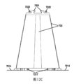
図35Aと図35Bには、それぞれ、本発明のさらに別の好適な実施形態による弾性モジュールの斜視図と側面図が例示的に示されている。図面に示すように、前記弾性モジュールは、錐形状スプリング110と複数のフレキシブルバンド123eとを含み、各フレキシブルバンド123eは、それぞれ、本体部分1231eと、前記本体部分の一端に位置する第一フック1232eと、前記本体部分の他端に位置する第二フック1233eとを含み。前記第一フック1232eが錐形状スプリングの大径端に取外可能に掛け、前記第二フック1233eが錐形状スプリングの小径端に取外可能に掛けるとともに、前記複数のフレキシブルバンド123eが、いずれも、錐形状スプリングの外側に位置する。好ましくは、前記複数のフレキシブルバンド123eの長さは、錐形状スプリングが予め決めた初期圧縮力を具備するように設計されている。さらに好ましくは、前記フレキシブルバンド123eは、一体成型されるものであるとともに、プラスチックで製作される。選択的に、前記フレキシブルバンド123eの本体部分1231eの幅及び/又は厚さは、一端から他端へ漸減している。
35A and 35B are respectively a perspective view and a side view of an elastic module according to another preferred embodiment of the present invention. As shown in the drawings, the elastic module includes a cone-shaped
図35Cと図35Dには、それぞれ、本発明のさらに別の好適な実施形態による弾性モジュールの斜視図と側面図が例示的に示されている。図面に示すように、前記弾性モジュールは、錐形状スプリング110と複数のフレキシブルバンド123fとを含み、各フレキシブルバンド123fは、それぞれ、本体部分1231fと、前記本体部分の一端に位置する第一フック1232fと、前記本体部分の他端に位置する第二フック1233fとを含む。前記第一フック1232fが錐形状スプリングの大径端に取外可能に掛け、前記第二フック1233fが錐形状スプリングの小径端に取外可能に掛けるとともに、前記複数のフレキシブルバンド123fが、いずれも、錐形状スプリングの外側に位置する。好ましくは、前記複数のフレキシブルバンド123fの長さは、錐形状スプリングが予め決めた初期圧縮力を具備するように設計されている。さらに好ましくは、前記フレキシブルバンド123fは、本体部分1231fが織物で製作され、第一フック1232fと第二フック1233fが金属又はプラスチックで製作される。選択的に、前記フレキシブルバンド123fの本体部分1231fの幅及び/又は厚さは、一端から他端へ漸減している。
35C and 35D are respectively a perspective view and a side view of an elastic module according to another preferred embodiment of the present invention. As shown in the drawings, the elastic module includes a cone-shaped
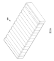
図35Eには、複数の図35A乃至図35Dに示す弾性モジュールが嵌め入れた時の様子が例示的に示されている。 Figure 35E shows an example of what the elastic modules shown in Figures 35A to 35D may look like when inserted.
図35Fと図35Gには、それぞれ、本発明のさらに別の好適な実施形態による弾性モジュールの分解図と断面図が例示的に示されており、図35Hは、図35Gの一部拡大図である。図面に示すように、前記弾性モジュールは、錐形状スプリング110と、閉鎖端と開放端を備える一体式フレキシブルカバー1231gと、一つまたは複数の締付具129gとを含む。前記錐形状スプリング110は、前記一体式フレキシブルカバー1231gの開放端を通してその内部に進入し、これによって、錐形状スプリングの外側において前記一体式フレキシブルカバーが包み、そして、そのうち、前記一体式フレキシブルカバー1231gの開放端の末端は、錐形状スプリング110の大径端を囲んで錐形状スプリングの内部へ折り曲げられ、前記一つまたは複数の締付具129gによって前記一体式フレキシブルカバー1231gにおける前記錐形状スプリング110の外側に位置する隣接部分に固着される(図35Hを参照)。好ましくは、前記一体式フレキシブルカバー1231gと前記一つまたは複数の締付具129gは、錐形状スプリングが予め決めた初期圧縮力を具備するようにお互いに連携される。一つの好適な実施形態において、前記一体式フレキシブルカバー1231gが一体式布カバーであり、前記締付具129gがリベッドである。図35Iには、複数の図35Fと図35Gに示す弾性モジュールが嵌め入れた時の様子が例示的に示されている。
35F and 35G are respectively an exploded view and a cross-sectional view of an elastic module according to another preferred embodiment of the present invention, and FIG. 35H is a partially enlarged view of FIG. 35G. As shown in the drawings, the elastic module includes a cone-shaped
図35Jには、本発明のさらに別の好適な実施形態による弾性モジュールが例示的に示されており、図35Kには、その錐形状スプリング110bが示されている。図35F乃至図35Hに示す弾性モジュールと異なるのは、その一体式フレキシブルカバー1231hと錐形状スプリング110bが角錐形である。
Figure 35J exemplarily shows an elastic module according to yet another preferred embodiment of the present invention, and Figure 35K shows its cone-shaped
図36Aと図36Bには、それぞれ、本発明のさらに別の好適な実施形態による弾性モジュールの斜視図と透過図が例示的に示されており、前記弾性モジュールは、列となり連続である複数の柱形布カバー1231iと、その内で包まれた複数の柱形スプリングとを含む。図36Cには、本発明のさらに別の好適な実施形態による弾性モジュールの斜視図が例示的に示されており、図36Dには、図36Cに示す弾性モジュールが圧縮されて収納箱に格納された時の様子が例示的に示され、図36Eには、複数の図36Dに示す収納箱が積み重ねた時の様子が例示的に示されている。 36A and 36B are respectively a perspective view and a see-through view of an elastic module according to another preferred embodiment of the present invention, the elastic module including a plurality of columnar fabric covers 1231i in a row and a plurality of columnar springs wrapped therein. FIG. 36C is a perspective view of an elastic module according to another preferred embodiment of the present invention, FIG. 36D is an example of the elastic module shown in FIG. 36C when compressed and stored in a storage box, and FIG. 36E is an example of the storage box shown in FIG. 36D when stacked.
図37には、本発明のさらに別の好適な実施形態による弾性モジュールの斜視図が例示的に示されている。図面に示すように、前記弾性モジュールは、錐形状スプリング110と、ベース121jと、複数のフレキシブルバンド123jとを含む。前記ベースはスプリング取付座を備え、前記スプリング取付座は、錐形状スプリングの大径端部を固着するためのスプリング固着部1212jを備え、各フレキシブルバンド123jの一端が前記ベースに固着的に接続され、他端には、錐形状スプリングの小径端部に取外可能に掛ける掛止部1233jを備え、前記複数のフレキシブルバンド123jは、いずれも、錐形状スプリング110の外側に位置する。好ましくは、前記複数のフレキシブルバンド123jの長さは、錐形状スプリング110が予め決めた初期圧縮力を具備するように設計される。さらに好ましくは、前記フレキシブルバンド123jは、全体がプラスチックで製作される。選択的に、前記フレキシブルバンド123jの本体部分が織物で製作され、掛止部1233jが金属又はプラスチックで製作される。選択的に、前記フレキシブルバンド123jの本体部分の幅及び/又は厚さは、一端から他端へ漸減している。一つの好適な実施形態において、前記ベース121jの底面には、弾性モジュールを弾性クッションに取外可能に取り付けるためのモジュール取付部1213jがさらに設置されている。好ましくは、モジュール取付部1213jが、前記ベースの底面に設置されるスライド軌道又はスライドレールであり、前記ベースがモジュール取付部1213jによって弾性クッションにおける取付枠に摺動可能に組み立てられることができる。別の好適な実施形態において、前記ベース121jには、図29A乃至図29Cに示すロック構造31、32、図30A乃至図30Cに示すロック構造41、42、図30D乃至図30Fに示すロック構造43、44、又は図31A乃至図31Dに示すT形(又は楔形)接続部51、がさらに設置されてもよい。
37 is an exemplary perspective view of an elastic module according to another preferred embodiment of the present invention. As shown in the drawing, the elastic module includes a cone-shaped
図38Aと図38Bには、それぞれ、本発明のさらに別の好適な実施形態による弾性モジュール(スプリングパッケージ)の分解斜視図と断面斜視図が例示的に示されている。図面に示すように、前記弾性モジュール(スプリングパッケージ)は、錐形状スプリング110と双層式のフレキシブルカバーとを含み、前記双層式のフレキシブルカバーは円錐台形外層123mと前記円錐台形外層123mの内側に位置する円錐台形内層123nとを含み、前記円錐台形外層が閉鎖端と開放端を備え、前記円錐台形外層の前記開放端が外側へ延びる第一フランジ1231mを備え、前記円錐台形内層123nが閉鎖端と開放端を備え、前記円錐台形内層123nの開放端が外側へ延びる第二フランジ1231nを備える。前記円錐台形内層123nの径方向寸法が前記円錐台形外層123mの径方向寸法より小さく、そして、前記円錐台形内層123nの高さ寸法が前記円錐台形外層123mの高さ寸法と大体等しく、前記錐形状スプリング110が前記円錐台形外層123mと前記円錐台形内層123nとの間に位置する。前記円錐台形外層123mの第一フランジ1231mと前記円錐台形内層123nの前記第二フランジ1231nとが固着的に接続されており、前記円錐台形外層の前記閉鎖端と前記円錐台形内層の前記閉鎖端とが固着的に接続されている。好ましくは、前記円錐台形外層123mの高さ寸法と前記円錐台形内層123nの高さ寸法とは、両者の間の錐形状スプリングが予め決めた初期圧縮力を具備するように設計される。好ましくは、前記円錐台形外層123mと前記円錐台形内層123nが粘接剤又は超音波溶接によって接続される。
38A and 38B are respectively an exploded perspective view and a cross-sectional perspective view of an elastic module (spring package) according to another preferred embodiment of the present invention. As shown in the drawings, the elastic module (spring package) includes a cone-shaped
図39Aと図39Bには、それぞれ、図38Aと図38Bに示すスプリングパッケージが異なる固着形態でベースに固着された時の様子が例示的に示されており、図39Aにおいて、スプリングパッケージがベースにおける係合部によってベースに固着的に接続される一方、図39Bにおいて、スプリングパッケージが締付具によってベースに固着的に接続される。図39Cには、複数の図39A又は図39Bに示す弾性モジュールが嵌め入れた時の様子が例示的に示されている。前記ベースには、図29A乃至図29Cに示すロック構造31、32、図30A乃至図30Cに示すロック構造41、42、図30D乃至図30Fに示すロック構造43、44、又は図31A乃至図31Dに示すT形(又は楔形)接続部51、がさらに設置されてもよい。
39A and 39B show examples of the spring packages shown in 38A and 38B fixed to the base in different fixing modes, respectively. In 39A, the spring package is fixedly connected to the base by the engagement portion of the base, while in 39B, the spring package is fixedly connected to the base by the fastener. In 39C, a plurality of elastic modules shown in 39A or 39B are shown fitted. The base may further be provided with
図40A乃至図40Cには、上記弾性モジュールに用いられる錐形状としないスプリングの別の実施例が例示的に示されており、図40Dには、図40Bに示すスプリングを備える弾性モジュールが例示的に示されている。図40Eには、上記弾性モジュールに用いられる錐形状スプリングの別の実施例が例示的に示されており、図40Fには、図40Eに示す錐形状スプリングを備える弾性モジュール200aが例示的に示されており、該弾性モジュール200aがスプリングサポーター220aとその内に取り付けられる角錐形状スプリング110bとを含む。
Figures 40A to 40C exemplarily show another embodiment of a non-pyramidal spring used in the elastic module, and Figure 40D exemplarily shows an elastic module having the spring shown in Figure 40B. Figure 40E exemplarily shows another embodiment of a pyramidal spring used in the elastic module, and Figure 40F exemplarily shows an
図40Gには、本発明の弾性モジュールに用いられる錐形状スプリングの別の実施例が例示的に示されており、そのうち、前記錐形状スプリングの少なくとも一部が、ダブル螺旋糸で形成され、好ましくは、ダブル螺旋糸を備えるダブル線スプリング部分が、前記錐形状スプリングの全体高さの約2/3を占める。図40Hには、図40Gに示す錐形状スプリングを備える弾性モジュールが例示的に示されている。 Figure 40G exemplarily illustrates another embodiment of a cone-shaped spring used in the elastic module of the present invention, in which at least a portion of the cone-shaped spring is formed with a double helical thread, and preferably the double wire spring portion with the double helical thread occupies about 2/3 of the total height of the cone-shaped spring. Figure 40H exemplarily illustrates an elastic module with the cone-shaped spring shown in Figure 40G.
一方、本発明は、上記のような各種の弾性モジュールを含む弾性クッションをさらに提供する。 Meanwhile, the present invention further provides an elastic cushion including various elastic modules as described above.
図41Aには、本発明の一つの好適な実施形態による弾性クッションが例示的に示されている。図面に示すように、前記弾性クッションは、以上の実施形態に記載された各種の弾性モジュールと、第一スポンジパッド1300aと、第二スポンジパッド1100aと、外カバー1200aとを含み、各第一スポンジパッドが複数の穴を備え、各穴が、その中から対応する弾性モジュールの一部が通過可能であるように構成され、第二スポンジパッド1100aが前記第一スポンジパッド1300aに嵌設され、カバー1200aが、第二スポンジパッド1100aに嵌設されることによって、前記弾性モジュールと第一スポンジパッドと第二スポンジパッドを包む。
Figure 41A shows an example of an elastic cushion according to one preferred embodiment of the present invention. As shown in the drawing, the elastic cushion includes various elastic modules described in the above embodiments, a
図41Bには、本発明のさらに別の好適な実施形態による弾性クッションが例示的に示されており、図41Aに示す弾性クッションと異なるのは、図41Cに示すように、前記第一スポンジパッド1300bが、並設される複数の独立部分を含み、各独立部分が、それぞれ、異なる硬さと色を備えてもよく、これによって、需要に応じてベッドパッドの異なる位置に設置され、区別しやすい。
Figure 41B illustrates an elastic cushion according to yet another preferred embodiment of the present invention. It differs from the elastic cushion shown in Figure 41A in that, as shown in Figure 41C, the
図41Dには、本発明のさらに別の好適な実施形態による弾性クッションが例示的に示されている。図面に示すように、図41Aと図41Bに示す弾性クッションと異なるのは、当該弾性クッションが固着網1400aをさらに備え、固着網1400aが複数の円環部を備え、各前記円環部が、その中から、対応する弾性モジュールの一部が通過可能であるように構成される。前記固着網1400aが弾性モジュールに設置されたとき、前記円環部の前記弾性モジュールの頂端からの垂直距離が前記弾性モジュールの全体高さの約1/3である。
Figure 41D shows an example of an elastic cushion according to yet another preferred embodiment of the present invention. As shown in the drawing, the elastic cushion is different from the elastic cushion shown in Figures 41A and 41B in that the elastic cushion further includes a
図42Aには、本発明の一つの好適な実施形態による弾性クッションに用いられる固着網アセンブリ1400bが例示的に示されており、図42Bには、図42Aに示す固着網アセンブリの一部断面図が例示的に示されている。図面に示すように、当該固着網アセンブリ1400bは、複数の穴を備えるフレキシブル片1410bと複数の帽部材1420bとを含み、前記フレキシブル片1410bの前記穴の位置が弾性モジュールの位置に対応し、各帽部材1420bが、弾性モジュールの頂端部分を収容するための凹腔1421bと、前記凹腔を囲むフランジ1422bとを備え、そのうち、凹腔1421bを形成する壁の寸法が前記穴の寸法よりも小さいことによって前記壁が前記穴を通すことができ、前記フランジ1422bの寸法が前記穴の寸法よりも大きいことによって前記フランジが穴の周囲の一部のフレキシブル片を接合でき、そして、そのうち、前記フランジ1422bが粘着剤又は超音波溶接によって前記穴の周囲の前記一部のフレキシブル片に固着的に接続され、前記凹腔1421bが弾性モジュールの頂部を収容できる。
Figure 42A illustrates an exemplary
図42Cには、本発明の一つの好適な実施形態による弾性クッションに用いられる固着網アセンブリ1400cの分解図が例示的に示されており、図面に示すように、前記固着網アセンブリ1400cは、穴を備えないフレキシブル片1410cと、前記フレキシブル片の一側に位置し且つそれぞれ第一係合特徴部1422c又は1422dを備える複数の上方帽部材1420c又は1420dと、前記フレキシブル片の他側に位置し且つそれぞれ第二係合特徴部1432c又は1432dを備える複数の下方帽部材1430c又は1430dとを含む。前記上方帽部材の前記第一係合特徴部は、前記下方帽部材の前記第二係合特徴部と係合されるとともに、前記フレキシブル片を前記上方帽部材と前記下方帽部材との間に挟まるように構成され、前記下方帽部材1430c、1430dが前記弾性モジュールの頂部を収容できる。
42C is an exemplary exploded view of a fastening
図42Dと図42Eには、上方帽部材1420cと下方帽部材1430cがフレキシブル片1410cを挟持する過程が例示的に示されており、図面に示すように、上方帽部材1420cが、環形状壁1421cと環形状壁1421cの外側に位置する環状凸起部1422cとを備え、下方帽部材1430cが円形孔1431cを備え、前記環状凸起部1422cが円形孔1431cのエッジ1432cに係合でき、これによって、両者の間にフレキシブル片1410cを挟持する。
Figures 42D and 42E show an example of the process in which the
図42Fと図42Gには、上方帽部材1420dと下方帽部材1430dがフレキシブル片1410cを挟持する過程が例示的に示されており、図面に示すように、前記帽部材1420c、1430cと異なるのは、上方帽部材1420dの環形状壁の内外側には、いずれも、環状凸起部1422dを備え、下方帽部材1430dには環形溝1431dを備え、環形溝1431dにおいて係合部1432dが設置され、前記環状凸起部1422dが環形溝1431dにおける係合部1432dに係合でき、これによって、両者の間にフレキシブル片1410cを挟持する。
Figures 42F and 42G show an example of the process in which the
図42Hには、本発明のさらに別の好適な実施形態による弾性クッションが例示的に示されており、図42Iには、当該弾性クッションの断面図が例示的に示されている。図面に示すように、当該弾性クッションは、以上の実施形態、特に図33J乃至図33Nに示す各種の弾性モジュールアセンブリを含む。当該実施形態の弾性クッションは、前記弾性モジュールアセンブリに敷設されるスプリングパッド1500aと、スプリングパッド1500aに覆われて弾性モジュールアセンブリとスプリングパッド1500aを包み、キルティングスポンジ層を備える外カバー1600aとをさらに含む。
Figure 42H shows an example of an elastic cushion according to yet another preferred embodiment of the present invention, and Figure 42I shows an example of a cross-sectional view of the elastic cushion. As shown in the drawings, the elastic cushion includes various elastic module assemblies as shown in the above embodiments, particularly Figures 33J to 33N. The elastic cushion of this embodiment further includes a
さらに、図42Lには、上記スプリングパッド1500aが例示的に示されており、図42Mには、スプリングパッド1500aの一部断面図が例示的に示されている。図面に示すように、前記スプリングパッド1500aは、複数の柱形スプリング1530aと、前記複数の柱形スプリング1530aの一側に位置する第一不織布層1510aと、前記複数の柱形スプリング1530aの他側に位置する第二不織布層1520aとを含む。第一不織布層1510aと前記第二不織布層1520aは、各柱形スプリング1530aの周囲において、粘着剤又は超音波溶接の形態で接続され、これによって、隣接する柱形スプリングを分隔し、前記柱形スプリングを前記2層の不織布層の間に固着し、一体式スプリングパッドを形成する。言い換えると、第一不織布層1510aと第二不織布層1520aは、各小柱形スプリング1530aの周囲において、粘着剤又は超音波溶接で接続され、前記複数の小柱形スプリングを収容するための仕切室を形成し、これによって、隣接する小柱形スプリングがお互いに分隔される。前記柱形スプリング1530aの弾性係数は、スポンジに近い硬さを提供するように、底層に位置する弾性モジュールにおけるスプリングの弾性係数よりも小さいことが好ましい。そして、前記複数の柱形スプリング1530aは、もっと良い快適さを提供するように、底層に位置する複数の弾性モジュールよりも密集することが好ましい。言い換えると、前記柱形スプリング1530aの径方向寸法は、前記弾性モジュールにおけるスプリングの径方向寸法よりも小さいことが好ましく、前記柱形スプリング1530aの数は、前記弾性モジュールの数よりも多いことが好ましい。スプリングパッド1500aは、スポンジパッドを代替することができ、快適であり、通気性があり、コストの節約が可能である。
Furthermore, FIG. 42L shows an example of the
図42Jには、本発明のさらに別の好適な実施形態による弾性クッションが例示的に示されており、図42Kには、当該弾性クッションの断面図が例示的に示されている。図面に示すように、当該弾性クッションは、以上の実施形態、特に図29A乃至図31Pに示す各種の弾性モジュール又は弾性モジュールアセンブリを含む。当該実施形態の弾性クッションは、同様に、前記弾性モジュールアセンブリに敷設されるスプリングパッド1500aと、スプリングパッド1500aに覆われて弾性モジュールアセンブリとスプリングパッド1500aを包み、キルティングスポンジ層を備える外カバー1600aとを含む。図42Hと図42Iに示す弾性クッションと異なるのは、当該実施形態の弾性クッションが、図42A乃至図42Gに示す固着網アセンブリ1400b又は1400cをさらに含む。当該固着網アセンブリ1400b又は1400cは、弾性モジュールとスプリングパッド1500aとの間に設置される。
Figure 42J exemplarily shows an elastic cushion according to yet another preferred embodiment of the present invention, and Figure 42K exemplarily shows a cross-sectional view of the elastic cushion. As shown in the drawings, the elastic cushion includes various elastic modules or elastic module assemblies shown in the above embodiments, particularly in Figures 29A to 31P. The elastic cushion of this embodiment also includes a
図42Nには、本発明のさらに別の好適な実施形態による弾性クッションが例示的に示されている。図42Jと図42Kに示す実施例と異なるのは、本実施例において、図41Aに示すスポンジパッド1300aで固着網アセンブリ1400b又は1400cを代替した。上記のように、スポンジパッド1300aが複数の穴を備え、各穴が、その中から、対応する弾性モジュールの一部が通過可能であるように構成される。類似的に、スポンジパッド1300aは、図41Bと図41Cに示された並設される複数の独立部分を含むスポンジパッド1300bに代替されてもよい。
FIG. 42N shows an example of an elastic cushion according to yet another preferred embodiment of the present invention. Different from the embodiment shown in FIG. 42J and FIG. 42K, in this embodiment, the
図42Pには、本発明のさらに別の好適な実施形態による弾性クッションが例示的に示されており、当該弾性クッションは、上記のようなスプリングパッド1500aとスプリングパッド1500aの外部に被る外カバー1700aとを含む。図面に示すように、外カバー1700aはキルティングスポンジ層1710aを備え、キルティングスポンジ層1710aがスプリングパッド1500aの上下両側に位置する。上記のように、スプリングパッド1500aにおけるスプリングの弾性係数が低いため、当該弾性クッションが圧縮状態で折曲でき、収納空間を節約でき、圧縮及折曲の過程は、図42Qに示すようになる。
Figure 42P illustrates an elastic cushion according to yet another preferred embodiment of the present invention, which includes the above-mentioned
図43Aには、本発明のさらに別の好適な実施形態による弾性クッションが例示的に示されている。図面に示すように、前記弾性クッションは、底布1200dと、第一外カバー1300dと、複数の前述実施形態に記載された弾性モジュールと、複数のスポンジブロック1400dと、を含み、そのうち、前記第一外カバーは、底端が開放され、頂端が閉鎖され、前記第一外カバー1300dの前記底端のエッジが前記底布1200dのエッジにミシン縫製されて閉合な収容空間を形成し、各弾性モジュールは、スプリングサポーターと前記スプリングサポーター内に取り付けられるスプリングとを含み、前記複数の弾性モジュールが前記収容空間内に設置され、前記複数のスポンジブロックが前記収容空間内に設置され、各スポンジブロックが、それぞれ、前記複数の弾性モジュールにおける対応する弾性モジュールの頂部に設置される。前記第一外カバー1300dは、独立の複数の仕切室を含み、各前記仕切室において、それぞれ、一つまたは複数の前記弾性モジュール及び一つまたは複数の前記スポンジブロック1400dが設置されている。前記底布1200dは複数の開口を備え、各前記開口は、前記複数の仕切室のうちの一つまたは複数の仕切室に対応するとともに、各前記開口において、各前記開口の開きと閉めのためのカーテン1210d及び前記カーテンに設置されたファスナー1220dが設置されている(図43Dを参照)。好ましくは、図43Bに示すように、前記弾性クッションは、第一外カバー1300dの外側に嵌設される第二外カバー1500dをさらに含んでもよい。
43A exemplarily shows an elastic cushion according to another preferred embodiment of the present invention. As shown in the drawing, the elastic cushion includes a
図43Cには、図43Aと図43Bに示す弾性クッションにおける仕切室を備える外カバー1300dが例示的に示されており、各仕切室の形状が同一である。
Figure 43C shows an example of an
図43Dと図43Eには、底布1200dがミシン縫製された第一外カバー1300dが例示的に示されており、図43Dにおいて、前記底布のカーテン1210d及びファスナー1220が開状態であり、図面より分かるように、前記底布の各細長い開口と外カバー1300dの一列の仕切室とが対応している。図43Eにおいて、前記底布のカーテン1210d及びファスナー1220が閉状態である。
Figures 43D and 43E show an example of a first
図43F乃至図43Hには、本発明の別な実施形態による異なる形状/寸法の仕切室を備える外カバーが例示的に示され、種類の異なる弾性モジュールを収容することに用いられることができる。図43Iには、本発明の一つの好適な実施形態によるハニカム形状(六角形)の仕切室を備える外カバーが例示的に示されている。 Figures 43F-43H show an example of an outer cover with compartments of different shapes/sizes according to another embodiment of the present invention, which can be used to accommodate different types of elastic modules. Figure 43I shows an example of an outer cover with honeycomb-shaped (hexagonal) compartments according to one preferred embodiment of the present invention.
図44A乃至図44Eには、本発明の別な実施形態によるスポンジブロックが例示的に示されており、図面より分かるように、スポンジブロックが平坦であってもよく、凸起又は凹みを備えてもよく、種類の異なる弾性モジュールに用いられる。 Figures 44A to 44E show an exemplary sponge block according to another embodiment of the present invention, and as can be seen from the drawings, the sponge block may be flat, may have protrusions or recesses, and may be used for different types of elastic modules.
図45Aには、本発明の一つの好適な実施形態によるスポンジブロックが例示的に示されている。図面に示すように、当該スポンジブロック1400dは、弾性モジュールの頂部を収容するための凹み部1410dと、凹み部1410dの四つの側面に位置しスポンジブロックの折畳と圧縮に寄与する溝1420dとを備え、図45Bには、折畳/圧縮状態である図45Aに示すスポンジブロックが例示的に示され、図45Cに示すように、折畳後のスポンジブロックが収納カップに収納できる。図46A乃至図46Cに示すように、スポンジブロック1400dは、自然状態で長尺形状の収納袋に置かれてもよく、スポンジブロックを満たした収納袋は、折り曲げてボックスに置かれてもよく、又は、包装されて固着されてもよい。
FIG. 45A shows an example of a sponge block according to one preferred embodiment of the present invention. As shown in the drawing, the
図47A乃至図47Cには、本発明によるスポンジブロックの他の包装方法が例示的に示されており、各スポンジブロック1400dが、圧縮されて一つのボックスに格納できる。
Figures 47A to 47C show an example of another packaging method for sponge blocks according to the present invention, in which each
図48A乃至図48Fには、本発明の一つの好適な実施形態によるスポンジブロックの収納箱及スポンジブロックの収納方法が例示的に示されている。図面に示すように、スポンジブロックの収納箱は、狭細い中空な四角体形状であり、前記スポンジブロックの収納箱の縦方向に沿う少なくとも一端には、スポンジブロック1400dを通過させて入れるための開口2010dを備える。スポンジブロックの収納箱は、その中に収納されたスポンジブロック1400dを容易に取り出すために、側壁の全体が開くことができ、収納箱盖2020dを形成する。開口2010dの周囲には、フランジ2030dが設置され、該フランジ2030dが、ポンジブロック1400dが開口2010dを介して収納箱から脱離することを回避するように、収納されたスポンジブロック1400dの周辺を受ける。選択的に、前記スポンジブロックの収納箱の縦方向他端にも、開口が設置されてもよい。
48A to 48F show an example of a sponge block storage box and a sponge block storage method according to one preferred embodiment of the present invention. As shown in the drawings, the sponge block storage box has a narrow hollow rectangular shape, and at least one end along the vertical direction of the sponge block storage box is provided with an
図49Aと図49Bには、本発明の一つの好適な実施形態による弾性クッションに用いられる外カバー2000dが例示的に示されており、前記外カバー2000dは、底端(図では、上端)が開放され、頂端(図では、底端)が閉鎖され、前記外カバー2000dは、四つのエッジ2110dを備える天面部分2100dと、四つの側面部分2200dとを含み、前記四つの側面部分における各側面部分が、それぞれ、前記天面部分2100dの前記四つのエッジ2110dにおける対応するエッジにミシン縫製されており、隣接する二つの側面部分2200dごとのそれぞれ隣接するエッジにおいて、いずれも、ファスナー2210dが設置されており、これによって、前記複数の弾性モジュールを部分的に包むように、前記側面部分2200dのそれぞれ隣接するエッジを脱離可能に接続される。好ましくは、前記天面部分2100dは、前記弾性クッションの内側から外側まで順に、不織布層、高弾性スポンジ層、不織布層、キルティングスポンジ層、真綿層と布材層を含み、各側面部分2200dは、前記弾性クッションの内側から外側まで順に、不織布層、キルティングスポンジ層、真綿層と布材層を含む。
Figures 49A and 49B show an example of an
好ましくは、各側面部分2200dは、それと一体にミシン縫製された仕上部分2300dを含み、各仕上部分が布材層のみを含む。
Preferably, each
一つの好適な実施形態において、前記弾性クッションは、仕上部分2200dに設置される一対又は複数対の紐2400dをさらに含み、該紐が、前記外カバーを前記複数の弾性モジュールと結ぶことに用いられる。
In one preferred embodiment, the elastic cushion further includes one or more pairs of
図50Aと図50Bは、本発明の別の好適な実施形態による弾性クッションに用いられる外カバーが例示的に示されている。図面に示すように、前記外カバー3000dは、閉合式外カバーであり、そして、天面部分3100dと、四つの側面部分3210d、3220d、3230d、3240dと、底面部分3300dとを含む。天面部分3100dの第一エッジは、第一側面部分3210dにミシン縫製され、該第一エッジに対向する天面部分の第二エッジは、第二側面部分3220dにミシン縫製され、底面部分3300dの第一エッジは、前記第一側面部分3210dにミシン縫製され、該第一エッジに垂直する底面部分3300dの二つのエッジは、それぞれ、第三側面部分3230dと第四側面部分3240dにミシン縫製される。そのうち、天面部分3100d、四つの側面部分3210d、3220d、3230d、3240d及び底面部分3300dの全てのミシン縫製されていないエッジにおいて、いずれも、ファスナー3400dが設置され、これによって、複数の弾性モジュールを包むように、前記ミシン縫製されていないエッジを脱離可能に一体に接続する。好ましくは、前記天面部分3100dは、前記弾性クッションの内側から外側まで順に、不織布層、高弾性スポンジ層、不織布層、キルティングスポンジ層、真綿層と布材層を含み、各側面部分3210d、3220d、3230d、3240dは、前記弾性クッションの内側から外側まで順に、不織布層、キルティングスポンジ層、真綿層と布材層を含み、前記底面部分3300dは、布材層のみを含む。
50A and 50B are illustrative diagrams showing an outer cover used in an elastic cushion according to another preferred embodiment of the present invention. As shown in the drawings, the
図51A乃至図51Cには、それぞれ、図面の形態で、図49A、図49B及び図50A、図50Bにおいて「AA」、「BB」、「CC」で標記された弾性クッションの外カバーの異なる部分の構成が示される。 Figures 51A to 51C show, in the form of drawings, the configurations of the different portions of the outer cover of the elastic cushions marked "AA", "BB", and "CC" in Figures 49A, 49B, 50A, and 50B, respectively.
以上の各実施形態に記載される各種のスプリング、スプリングサポーター、ベース、エンドカバー、フレキシブルバンド、フレキシブルカバー、各種の機能的アセンブリ/部材(例えば、弾性モジュールを取付枠に取り付けるためのモジュール取付部、隣接する弾性モジュールの間の相対的な位置関係に対する制限又は固着のための各種の係合部/アセンブリ、固着部/アセンブリ、ロック構造/アセンブリ、制限具など)が、必要に応じて任意に組み合わせて、異なる弾性モジュールを形成してもよいことは、当業者にとって認識されている。また、以上の各実施形態に記載されるスプリングパッケージ、弾性モジュール、取付枠、スポンジカバー、スポンジブロック、固着網、弾性クッション外カバー、弾性クッション底布などは、必要に応じて任意に組み合わせて、異なる弾性クッションを形成してもよい。 Those skilled in the art will recognize that the various springs, spring supporters, bases, end covers, flexible bands, flexible covers, and various functional assemblies/members (e.g., module mounting parts for mounting the elastic module to the mounting frame, various engagement parts/assemblies for restricting or fixing the relative positional relationship between adjacent elastic modules, fixing parts/assemblies, locking structures/assemblies, limiters, etc.) described in each of the above embodiments may be arbitrarily combined as needed to form different elastic modules. In addition, the spring packages, elastic modules, mounting frames, sponge covers, sponge blocks, fixing nets, elastic cushion outer covers, elastic cushion bottom cloths, etc. described in each of the above embodiments may be arbitrarily combined as needed to form different elastic cushions.
本発明の保護範囲は、特許請求の範囲だけによるものである。本発明の教示に基づき、当業者は、本発明に開示された構造の置換構造を、実行可能な置換実施形態とすることや、本発明に開示された実施形態を組み合わせて新たな実施形態を生み出すことを容易に想起でき、これらも同様に、添付された特許請求の範囲に入る。 The scope of protection of the present invention is determined solely by the claims. Based on the teachings of the present invention, a person skilled in the art can easily imagine the replacement structures of the structures disclosed in the present invention as feasible replacement embodiments, or the combination of the embodiments disclosed in the present invention to create new embodiments, which also fall within the scope of the appended claims.
Claims (25)
前記弾性モジュールは、
錐形状スプリング(110;110a;110b)と、
複数のフレキシブルバンド(123e;123f)と、を含み、
各前記フレキシブルバンドは、それぞれ、
第一端と、前記第一端と前記フレキシブルバンドの長手方向に沿って対向する第二端とを含む、帯形状の本体部分(1231e;1231f)と、
前記本体部分の前記第一端に位置する第一フック(1232e;1232f)と、
前記本体部分の前記第二端に位置する第二フック(1233e;1233f)と、を含み、
前記第一フックは、前記錐形状スプリングの大径端に取外可能に掛けられるように構成され、前記第二フックは、前記錐形状スプリングの小径端に取外可能に掛けられるように構成され、
前記第一フックと前記第二フックがそれぞれ前記錐形状スプリングに掛けたとき、前記複数のフレキシブルバンドが前記錐形状スプリングの外側に位置する、弾性モジュール。 An elastic module of an elastic cushion for making furniture, comprising:
The elastic module is
A cone-shaped spring (110; 110a; 110b),
a plurality of flexible bands (123e; 123f);
Each of the flexible bands is
a band-shaped main body portion (1231e; 1231f) including a first end and a second end opposite the first end along a longitudinal direction of the flexible band;
a first hook (1232e; 1232f) located at the first end of the body portion;
a second hook (1233e; 1233f) located at the second end of the body portion;
The first hook is configured to be removably hooked onto a large diameter end of the cone-shaped spring, and the second hook is configured to be removably hooked onto a small diameter end of the cone-shaped spring ,
An elastic module , wherein when the first hook and the second hook are respectively hooked onto the cone-shaped spring, the plurality of flexible bands are positioned outside the cone-shaped spring .
前記弾性クッションは、
複数の請求項1乃至8のいずれか一項に記載の弾性モジュールと、
複数の穴を備え、各穴が、その中から対応する弾性モジュールの一部が通過可能であるように構成される、第一スポンジパッド(1300a;1300b)と、
一つ又は複数の前記第一スポンジパッドに敷設される、第二スポンジパッド(1100a)と、
前記第二スポンジパッドに覆われることによって、前記弾性モジュールと前記第一スポンジパッドと前記第二スポンジパッドを包む、外カバー(1200a)と、を含む、弾性クッション。 A resilient cushion for furniture, comprising:
The elastic cushion is
A plurality of elastic modules according to any one of claims 1 to 8 ;
a first sponge pad (1300a; 1300b) having a plurality of holes, each hole being configured to allow a portion of a corresponding elastic module to pass therethrough;
A second sponge pad (1100a) laid on one or more of the first sponge pads;
An elastic cushion comprising: an outer cover (1200a) that is covered by the second sponge pad to encase the elastic module, the first sponge pad, and the second sponge pad.
前記固着網アセンブリは、
複数の穴を備えるフレキシブル片(1410b)と、
複数の帽部材(1420b)と、を含み、
各前記帽部材が、凹腔(1421b)と、前記凹腔を囲んで延びるフランジ(1422b)とを備え、
前記穴の寸法は、前記凹腔を形成する壁の寸法よりも大きく、且つ前記フランジの寸法よりも小さいことによって、前記壁が前記穴を通すことができ、前記フランジが前記穴の周囲のフレキシブル片の部分を接合でき、
前記フランジが粘着剤又は超音波溶接によって前記穴の周囲の前記フレキシブル片の部分に固着的に接続され、
前記凹腔が前記弾性モジュールの頂部を収容できる構成される、請求項9に記載の弾性クッション。 The resilient cushion further comprises an anchoring netting assembly (1400b);
The anchoring net assembly comprises:
a flexible piece (1410b) having a plurality of holes;
a plurality of cap members (1420b);
Each cap member includes a cavity (1421b) and a flange (1422b) extending around the cavity;
a size of the hole is larger than a size of the wall forming the cavity and smaller than a size of the flange, so that the wall can pass through the hole and the flange can join a portion of the flexible piece around the hole;
the flange is fixedly connected to the portion of the flexible piece surrounding the hole by adhesive or ultrasonic welding;
The resilient cushion of claim 9 , wherein the recess is configured to accommodate a top portion of the resilient module.
前記固着網アセンブリは、
穴を備えないフレキシブル片(1410c)と、
前記フレキシブル片の一側に位置し且つそれぞれ第一係合特徴部(1422c;1422d)を備える複数の上方帽部材(1420c;1420d)と、
前記フレキシブル片の他側に位置し且つそれぞれ第二係合特徴部(1432c;1432d)を備える複数の下方帽部材(1430c;1430d)と、を含み、
前記上方帽部材の前記第一係合特徴部は、前記下方帽部材の前記第二係合特徴部と係合されるとともに、前記フレキシブル片を前記上方帽部材と前記下方帽部材との間に挟まるように構成され、
前記下方帽部材が前記弾性モジュールの頂部を収容できるように構成される、請求項9に記載の弾性クッション。 The resilient cushion further comprises an anchoring netting assembly (1400c);
The anchoring net assembly comprises:
A flexible piece (1410c) without holes;
a plurality of upper cap members (1420c; 1420d) located on one side of the flexible piece and each having a first engagement feature (1422c; 1422d);
a plurality of lower cap members (1430c; 1430d) located on the other side of the flexible piece and each of the lower cap members having a second engagement feature (1432c; 1432d);
the first engagement feature of the upper cap member is configured to engage with the second engagement feature of the lower cap member and to sandwich the flexible piece between the upper cap member and the lower cap member;
The resilient cushion of claim 9 , wherein the lower cap member is configured to receive a top portion of the resilient module.
前記弾性モジュールは、
大径端部と前記大径端部に対向する小径端部とを備える、錐形状スプリング(110;110a;110b)と、
前記錐形状スプリングの前記大径端部を固着できるように構成されるスプリング固着部(1212j)を備える、ベース(121j)と、
複数のフレキシブルバンド(123j)と、を含み、
各前記フレキシブルバンドは、帯形状の本体部分と、前記ベースと固着的に接続される第一端部と、前記第一端部に対向し且つフック(1233j)を備える第二端部と、を有し、前記フックが前記錐形状スプリングの小径端部に取外可能に掛け、
前記複数のフレキシブルバンドは、前記フックが前記錐形状スプリングの小径端部に掛けたとき、前記錐形状スプリングの外側に位置する、弾性モジュール。 An elastic module of an elastic cushion for making furniture, comprising:
The elastic module is
A cone-shaped spring (110; 110a; 110b) having a large diameter end and a small diameter end opposite the large diameter end;
A base (121j) including a spring fixing portion (1212j) configured to fix the large diameter end of the cone-shaped spring;
a plurality of flexible bands (123j);
Each of the flexible bands has a belt-shaped body portion, a first end portion fixedly connected to the base, and a second end portion opposite the first end portion and having a hook (1233j), the hook portion removably hooking onto the small diameter end portion of the cone-shaped spring ;
The flexible bands are positioned outside the cone-shaped spring when the hooks are hooked onto the small diameter end of the cone-shaped spring, an elastic module.
Priority Applications (2)
| Application Number | Priority Date | Filing Date | Title |
|---|---|---|---|
| JP2023182926A JP7760570B2 (en) | 2019-10-17 | 2023-10-25 | Elastic module and elastic cushion for furniture |
| JP2025118841A JP2025137649A (en) | 2019-10-17 | 2025-07-15 | Elastic module and elastic cushion for furniture |
Applications Claiming Priority (5)
| Application Number | Priority Date | Filing Date | Title |
|---|---|---|---|
| CN201910990436.2 | 2019-10-17 | ||
| CN201910990436 | 2019-10-17 | ||
| CN202011104641.3A CN112674538A (en) | 2019-10-17 | 2020-10-15 | Elastic module and elastic cushion for furniture |
| CN202011104641.3 | 2020-10-15 | ||
| PCT/CN2020/121385 WO2021073590A1 (en) | 2019-10-17 | 2020-10-16 | Elastic module and elastic pad for furniture |
Related Child Applications (1)
| Application Number | Title | Priority Date | Filing Date |
|---|---|---|---|
| JP2023182926A Division JP7760570B2 (en) | 2019-10-17 | 2023-10-25 | Elastic module and elastic cushion for furniture |
Publications (3)
| Publication Number | Publication Date |
|---|---|
| JP2022552702A JP2022552702A (en) | 2022-12-19 |
| JPWO2021073590A5 JPWO2021073590A5 (en) | 2023-10-12 |
| JP7672400B2 true JP7672400B2 (en) | 2025-05-07 |
Family
ID=75445691
Family Applications (8)
| Application Number | Title | Priority Date | Filing Date |
|---|---|---|---|
| JP2022522806A Active JP7598372B2 (en) | 2019-10-17 | 2020-10-16 | Elastic module and elastic cushion for furniture |
| JP2022522925A Active JP7592081B2 (en) | 2019-10-17 | 2020-10-16 | Elastic module and elastic cushion for furniture |
| JP2022522636A Active JP7494294B2 (en) | 2019-10-17 | 2020-10-16 | Elastic cushions for furniture |
| JP2022522639A Active JP7556952B2 (en) | 2019-10-17 | 2020-10-16 | Elastic module and elastic cushion for furniture |
| JP2022522915A Active JP7672400B2 (en) | 2019-10-17 | 2020-10-16 | Elastic module and elastic cushion for furniture |
| JP2022522904A Active JP7597490B2 (en) | 2019-10-17 | 2020-10-16 | Elastic module and elastic cushion for furniture |
| JP2023182926A Active JP7760570B2 (en) | 2019-10-17 | 2023-10-25 | Elastic module and elastic cushion for furniture |
| JP2025118841A Pending JP2025137649A (en) | 2019-10-17 | 2025-07-15 | Elastic module and elastic cushion for furniture |
Family Applications Before (4)
| Application Number | Title | Priority Date | Filing Date |
|---|---|---|---|
| JP2022522806A Active JP7598372B2 (en) | 2019-10-17 | 2020-10-16 | Elastic module and elastic cushion for furniture |
| JP2022522925A Active JP7592081B2 (en) | 2019-10-17 | 2020-10-16 | Elastic module and elastic cushion for furniture |
| JP2022522636A Active JP7494294B2 (en) | 2019-10-17 | 2020-10-16 | Elastic cushions for furniture |
| JP2022522639A Active JP7556952B2 (en) | 2019-10-17 | 2020-10-16 | Elastic module and elastic cushion for furniture |
Family Applications After (3)
| Application Number | Title | Priority Date | Filing Date |
|---|---|---|---|
| JP2022522904A Active JP7597490B2 (en) | 2019-10-17 | 2020-10-16 | Elastic module and elastic cushion for furniture |
| JP2023182926A Active JP7760570B2 (en) | 2019-10-17 | 2023-10-25 | Elastic module and elastic cushion for furniture |
| JP2025118841A Pending JP2025137649A (en) | 2019-10-17 | 2025-07-15 | Elastic module and elastic cushion for furniture |
Country Status (13)
| Country | Link |
|---|---|
| US (11) | US12239231B2 (en) |
| EP (10) | EP4046542B1 (en) |
| JP (8) | JP7598372B2 (en) |
| KR (4) | KR102858176B1 (en) |
| CN (12) | CN112674540B (en) |
| AU (7) | AU2020367917A1 (en) |
| CA (7) | CA3155050A1 (en) |
| CL (4) | CL2022000963A1 (en) |
| DK (2) | DK4046542T3 (en) |
| ES (4) | ES3013998T3 (en) |
| GB (7) | GB2620298B (en) |
| MX (3) | MX2022004437A (en) |
| WO (10) | WO2021073602A1 (en) |
Families Citing this family (66)
| Publication number | Priority date | Publication date | Assignee | Title |
|---|---|---|---|---|
| US9848709B2 (en) * | 2015-06-04 | 2017-12-26 | Donald J. Molenda | Multi layered modular support system for lounge and other applications |
| WO2021026013A1 (en) * | 2019-08-02 | 2021-02-11 | The Regents Of The University Of California | Multi-stable compliant-mechanism mattress for bed sore prevention |
| CN112674540B (en) * | 2019-10-17 | 2024-11-05 | 厦门新技术集成有限公司 | Elastic modules and elastic pads for furniture |
| USD1032244S1 (en) * | 2020-06-12 | 2024-06-25 | New-Tec Integration (Xiamen) Co., Ltd. | Spring module |
| CN115251636A (en) * | 2021-04-29 | 2022-11-01 | 厦门新技术集成有限公司 | Sofa bed |
| US20220346562A1 (en) * | 2021-04-29 | 2022-11-03 | Zachariah Clarence Holtquist | Mattress |
| CN115251639B (en) * | 2021-04-29 | 2024-10-25 | 厦门新技术集成有限公司 | Sofa Bed |
| CN115251653B (en) * | 2021-04-30 | 2023-10-27 | 厦门新技术集成有限公司 | Spring bags, spring cushions, furniture and methods of making spring bags |
| CN115191785B (en) * | 2021-08-12 | 2023-08-11 | 厦门新技术集成有限公司 | Resilient Modular Balance Pads, Resilient Pads and Furniture |
| CN115191782B (en) * | 2021-08-12 | 2023-07-04 | 厦门新技术集成有限公司 | Elastic module balance pad, elastic pad and furniture |
| CN115191777A (en) * | 2021-08-12 | 2022-10-18 | 厦门新技术集成有限公司 | Elastic module balance pad, elastic pad and furniture |
| CN115191779A (en) * | 2021-08-31 | 2022-10-18 | 厦门新技术集成有限公司 | Elastic cushion, side enclosure, elastic cushion layer and furniture |
| CN115191780B (en) * | 2021-08-31 | 2024-03-19 | 厦门新技术集成有限公司 | Elastic pad and furniture |
| CN119564016A (en) * | 2021-08-31 | 2025-03-07 | 厦门新技术集成有限公司 | Method for custom assembling a resilient cushion for a user to sit or lie on |
| CN115191783A (en) * | 2021-08-31 | 2022-10-18 | 厦门新技术集成有限公司 | Elastic modules, elastic cushions and furniture |
| CN115191784B (en) * | 2021-08-31 | 2023-12-29 | 厦门新技术集成有限公司 | Removable elastic cushions, furniture and assembly methods |
| CN115336886B (en) * | 2021-09-30 | 2024-07-23 | 厦门新技术集成有限公司 | Elastic pads, additional elastic padding and furniture |
| CN115590332A (en) * | 2021-12-02 | 2023-01-13 | 厦门新技术集成有限公司(Cn) | Elastic support module, elastic cushion and furniture |
| CN115813148B (en) * | 2022-02-15 | 2023-12-15 | 厦门新技术集成有限公司 | Elastic modules and elastic cushions for furniture |
| CN115813147B (en) * | 2022-02-15 | 2024-03-22 | 厦门新技术集成有限公司 | Elastic cushion and furniture with the elastic cushion |
| CN114698972B (en) * | 2022-03-17 | 2023-09-29 | 深圳市领为创新科技有限公司 | Intelligence house sleep health control mattress |
| CN116098414A (en) * | 2022-04-08 | 2023-05-12 | 厦门新技术集成有限公司 | Balance pad cores, balance pads, resilient pads and furniture |
| US20230404267A1 (en) * | 2022-06-08 | 2023-12-21 | Hunkerin Stool, LLC | Squatting stool |
| CN115813150A (en) * | 2022-06-17 | 2023-03-21 | 厦门新技术集成有限公司 | Elastic pad, elastic pad assembly method and furniture |
| WO2023241038A1 (en) | 2022-06-17 | 2023-12-21 | 冷鹭浩 | Elastic cushion, elastic cushion assembly method, and furniture |
| CN217743729U (en) * | 2022-06-17 | 2022-11-08 | 厦门新技术集成有限公司 | Elastic mattress |
| CN218683234U (en) * | 2022-07-26 | 2023-03-24 | 浙江永强集团股份有限公司 | Protective cover and outdoor furniture with protective cover |
| CN117752191A (en) * | 2022-09-16 | 2024-03-26 | 厦门新技术集成有限公司 | Elastic module unit, elastic pad and furniture |
| CN117752190A (en) * | 2022-09-16 | 2024-03-26 | 厦门新技术集成有限公司 | Flexible modules, flexible cushions and furniture |
| CN117752189A (en) * | 2022-09-16 | 2024-03-26 | 厦门新技术集成有限公司 | Elastic module storage bracket, storage device, elastic pad, use method of elastic module storage bracket and storage device and furniture |
| CN115670171B (en) | 2022-10-24 | 2025-09-26 | 厦门新技术集成有限公司 | Flexible modular units, flexible mats and furniture |
| CN118285644A (en) * | 2023-01-04 | 2024-07-05 | 厦门新技术集成有限公司 | Cover, elastic pad and furniture |
| CN115998114A (en) * | 2023-01-05 | 2023-04-25 | 厦门新技术集成有限公司 | Storage Box and Elastic Pad Unit |
| CN116172360B (en) * | 2023-01-31 | 2025-12-09 | 厦门新技术集成有限公司 | Elastic pad and elastic assembly for elastic pad |
| CN116326958B (en) * | 2023-01-31 | 2025-09-26 | 厦门新技术集成有限公司 | elastic pad |
| CN116473388B (en) * | 2023-01-31 | 2026-01-23 | 厦门新技术集成有限公司 | Elastic cushion |
| CN116268865B (en) * | 2023-02-07 | 2025-12-16 | 广东国展科技有限公司 | Intelligent lifting mattress capable of balancing body stress |
| CN116439538B (en) * | 2023-02-22 | 2025-09-26 | 厦门新技术集成有限公司 | Elastic pad and elastic component for elastic pad |
| CN118556999A (en) * | 2023-02-28 | 2024-08-30 | 厦门新技术集成有限公司 | Elastic module and elastic pad |
| JP7795791B2 (en) * | 2023-03-08 | 2026-01-08 | 株式会社ルービックJp | Cushion body |
| CN116250695A (en) * | 2023-03-23 | 2023-06-13 | 厦门新技术集成有限公司 | Elastic unit, elastic module and elastic pad |
| USD1064792S1 (en) * | 2023-03-29 | 2025-03-04 | New-Tec Integration (Xiamen) Co., Ltd. | Spring module |
| USD1099607S1 (en) * | 2023-04-26 | 2025-10-28 | New-Tec Integration (Xiamen) Co., Ltd. | Spring module |
| CN116763095A (en) * | 2023-05-05 | 2023-09-19 | 厦门新技术集成有限公司 | Balance plate and flexible pad with same |
| JP1779395S (en) * | 2023-11-01 | 2024-09-06 | Pocket coil connector for mattresses | |
| CN120093114A (en) * | 2023-12-05 | 2025-06-06 | 厦门新技术集成有限公司 | A spring module structure, spring pad and soft pad for single spring installation |
| EP4585106A1 (en) * | 2023-12-14 | 2025-07-16 | New-Tec Integration (Xiamen) Co., Ltd. | Spring module configured to be compressed for storage and elastic module, elastic mattress |
| CN221949541U (en) * | 2023-12-14 | 2024-11-05 | 厦门新技术集成有限公司 | Elastic module and elastic pad with bottom plate connection structure |
| CN120154206A (en) * | 2023-12-14 | 2025-06-17 | 厦门新技术集成有限公司 | An elastic pad with an open elastic layer and its application |
| CN221489536U (en) * | 2023-12-14 | 2024-08-09 | 厦门新技术集成有限公司 | A modular camping mattress |
| CN118161040A (en) * | 2023-12-14 | 2024-06-11 | 厦门新技术集成有限公司 | A spring elastic pad |
| CN120154207A (en) * | 2023-12-14 | 2025-06-17 | 厦门新技术集成有限公司 | An elastic pad |
| USD1091196S1 (en) * | 2024-01-02 | 2025-09-02 | Luhao Leng | Spring waist ring |
| CN120436450A (en) * | 2024-02-07 | 2025-08-08 | 厦门新技术集成有限公司 | A flexible pad customized for soft and hard |
| USD1098789S1 (en) * | 2024-02-20 | 2025-10-21 | Luhao Leng | Body of mattress cushion |
| CN120643068A (en) * | 2024-03-15 | 2025-09-16 | 厦门新技术集成有限公司 | Spring connection structure, row spring, elastic pad and application of elastic pad |
| CN120643066A (en) * | 2024-03-15 | 2025-09-16 | 厦门新技术集成有限公司 | Elastic module with large supporting area and elastic pad |
| CN120720354A (en) * | 2024-03-29 | 2025-09-30 | 厦门新技术集成有限公司 | A spring with a positioning ring and an elastic pad |
| CN120788361A (en) * | 2024-04-03 | 2025-10-17 | 厦门新技术集成有限公司 | Connection structure, elastic layer and sofa bed of sofa bed elastic element |
| CN120836900A (en) * | 2024-04-25 | 2025-10-28 | 厦门新技术集成有限公司 | Elastic module and elastic pad |
| CN120836901A (en) * | 2024-04-25 | 2025-10-28 | 厦门新技术集成有限公司 | Elastic module, elastic pad and furniture |
| CN120938219A (en) * | 2024-05-13 | 2025-11-14 | 厦门新技术集成有限公司 | An elastic module and an elastic pad |
| WO2025252200A1 (en) * | 2024-06-07 | 2025-12-11 | 厦门新技术集成有限公司 | Spring unit having expandable top supporting surface, spring module, and elastic pad |
| CN121196308A (en) * | 2024-06-26 | 2025-12-26 | 厦门新技术集成有限公司 | Inverted spring module structure and spring net |
| CN121196309A (en) * | 2024-06-26 | 2025-12-26 | 厦门新技术集成有限公司 | Double-layer elastic unit structure capable of being spliced and disassembled and functional pad |
| WO2026002188A1 (en) * | 2024-06-27 | 2026-01-02 | 厦门新技术集成有限公司 | Spring module, release method therefor, and elastic pad |
Citations (5)
| Publication number | Priority date | Publication date | Assignee | Title |
|---|---|---|---|---|
| JP2012523916A (en) | 2009-04-14 | 2012-10-11 | シーリー テクノロジー エルエルシー | Coil-in coil spring and inner spring |
| CN102894722A (en) | 2012-11-05 | 2013-01-30 | 曾庆义 | Elastic support component for spring mattress and spring mattress |
| CN202874624U (en) | 2012-09-19 | 2013-04-17 | 蔡聪礼 | Mattress |
| US20180199728A1 (en) | 2016-06-03 | 2018-07-19 | Luhao Leng | Furniture construction with elastic or spring modules |
| JP2019162204A (en) | 2018-03-19 | 2019-09-26 | 株式会社タイカ | Spring structure connection body, mattress, and chair |
Family Cites Families (352)
| Publication number | Priority date | Publication date | Assignee | Title |
|---|---|---|---|---|
| BE459900A (en) * | 1945-08-30 | 1945-09-29 | Improvements to springs for furniture | |
| US66390A (en) * | 1867-07-02 | of burlington | ||
| US89651A (en) * | 1869-05-04 | Improved spring-bed bottom | ||
| US46573A (en) * | 1865-02-28 | Improved spring-mattress | ||
| US606683A (en) * | 1898-07-05 | Spring bed-bottom | ||
| US392009A (en) * | 1888-10-30 | Bed-bottom | ||
| US288533A (en) * | 1883-11-13 | Simeon p | ||
| US446203A (en) * | 1891-02-10 | john s | ||
| US97705A (en) * | 1869-12-07 | Improved coil-spring and its attachments | ||
| US488555A (en) * | 1892-12-20 | Emil g | ||
| US111364A (en) * | 1871-01-31 | Improvement in bedsteads and spring bed-bottoms | ||
| US102867A (en) * | 1870-05-10 | Improvement in the connection op springs for bed-bottoms, seats | ||
| US110293A (en) * | 1870-12-20 | Improvement in springs for beds, sofas | ||
| US348539A (en) * | 1886-08-31 | Spring bed-bottom | ||
| US42053A (en) * | 1864-03-22 | Improved spring for furniture | ||
| US179007A (en) * | 1876-06-20 | Improvement in spring bed-bottoms | ||
| US543994A (en) * | 1895-08-06 | Wire bed-bottom | ||
| US101526A (en) * | 1870-04-05 | Improved spring-bed bottom | ||
| US90303A (en) * | 1869-05-18 | Improved bed-bottom | ||
| US122111A (en) * | 1871-12-26 | Improvement in springs for upholstery purposes | ||
| US735006A (en) * | 1902-05-24 | 1903-07-28 | Joel Watkins | Spring for beds, couches, &c. |
| US840522A (en) * | 1906-03-03 | 1907-01-08 | Ventilated Cushion And Spring Company | Spring structure. |
| US837751A (en) * | 1906-09-10 | 1906-12-04 | Edgar Webster Summers | Convertible spring seat and bed. |
| US882600A (en) * | 1907-06-14 | 1908-03-24 | Albert Weborg | Furniture-spring. |
| US912855A (en) * | 1908-06-12 | 1909-02-16 | Fred B King | Spring. |
| US986723A (en) * | 1910-11-14 | 1911-03-14 | Nat Spring And Wire Company | Spring-seat construction. |
| US1037729A (en) * | 1911-08-26 | 1912-09-03 | Robert J Collins | Spring. |
| US1150712A (en) * | 1912-07-05 | 1915-08-17 | Watson R Smith | Spring structure. |
| US1127198A (en) * | 1914-01-12 | 1915-02-02 | Frank P D Arcy | Spring structure. |
| US1146933A (en) * | 1914-11-06 | 1915-07-20 | Richard D Gallagher Jr | Friction-spring. |
| US1203051A (en) * | 1916-04-29 | 1916-10-31 | Leonard A Young | Border-strip for spring-cushions. |
| US1226737A (en) * | 1916-08-31 | 1917-05-22 | Leonard A Young | Rim-strip. |
| US1287662A (en) | 1917-06-02 | 1918-12-17 | Foster Brothers Mfg Co | Covered-spring structure. |
| US1271672A (en) * | 1917-08-18 | 1918-07-09 | James J Crowley | Mattress. |
| US1343565A (en) * | 1918-07-03 | 1920-06-15 | Cushion Spring Engineering Cor | Spring structure |
| US1292745A (en) * | 1918-11-22 | 1919-01-28 | L A Young Ind Inc | Cushion-spring. |
| US1333801A (en) * | 1918-11-22 | 1920-03-16 | fitzgerald | |
| US1329145A (en) * | 1919-08-16 | 1920-01-27 | Seelig Joseph | Metallic bed-bottom |
| US1404464A (en) * | 1920-12-13 | 1922-01-24 | Adolph F Meyer | Spring |
| US1476046A (en) * | 1921-03-10 | 1923-12-04 | Frank J Brandel | Upholstery spring |
| US1410039A (en) * | 1921-09-29 | 1922-03-21 | Peter J Steinbach | Seat spring |
| US1434653A (en) * | 1922-06-07 | 1922-11-07 | Fiss David | Spring cushion |
| GB202802A (en) * | 1922-07-05 | 1923-08-30 | Harry Ashmore | Improvements in or relating to the mounting and protecting of upholstery and like springs |
| US1597012A (en) * | 1924-07-05 | 1926-08-24 | Julius L Cable | Upholstery support |
| US1684234A (en) * | 1924-08-02 | 1928-09-11 | Lipps Morris | Spring-cushion construction |
| US1544416A (en) * | 1925-04-09 | 1925-06-30 | Fred A Nachman | Method of making spring assemblies for upholstery |
| US1703587A (en) * | 1926-07-28 | 1929-02-26 | Kraft Harry | Mattress |
| US1718522A (en) * | 1926-11-08 | 1929-06-25 | Brandreth Charles Albert | Support for wire mattresses |
| FR657648A (en) * | 1927-07-22 | 1929-05-24 | Improvements to box springs or spring seats, spring support surfaces or the like | |
| BE354981A (en) * | 1928-10-08 | |||
| GB327954A (en) * | 1928-12-13 | 1930-04-14 | Louis Alexander Suekoff | Improvements relating to mattresses |
| US1767632A (en) * | 1929-06-22 | 1930-06-24 | Simon L Warren | Upholstery-frame attachment |
| US1898491A (en) | 1929-07-03 | 1933-02-21 | Owen Automatic Spring And Mach | Spring structure |
| US1804821A (en) | 1929-07-05 | 1931-05-12 | L A Young Spring & Wire Corp | Spring structure |
| US1908710A (en) * | 1930-06-27 | 1933-05-16 | Kronheim Jacob | Upholstered furniture |
| US1944614A (en) * | 1930-11-26 | 1934-01-23 | James P Salmon | Upholstery construction |
| US1914661A (en) * | 1931-03-07 | 1933-06-20 | Charles F Burke | Mattress |
| GB376291A (en) * | 1931-04-02 | 1932-07-04 | Francis Henry Carter | Improvements in resilient surfaces for beds, seats, cushions and upholstery |
| US1899188A (en) * | 1931-11-30 | 1933-02-28 | L A Young Spring & Wire Corp | Spring structure |
| US1927722A (en) * | 1932-04-09 | 1933-09-19 | Norman L Stoerkel | Spring unit |
| US1926085A (en) * | 1932-06-06 | 1933-09-12 | Pierce H Deamer | Double deck spring |
| US2048637A (en) * | 1934-04-13 | 1936-07-21 | Lisson Melen Co | Spring assembly for upholstery |
| GB457044A (en) * | 1935-05-18 | 1936-11-18 | Harold Arthur Slater | Improvements in or relating to spring seats, cushions, mattresses and the like |
| US2077036A (en) * | 1935-07-15 | 1937-04-13 | Leggett And Piatt Spring Bed A | Spring structure |
| US2100543A (en) * | 1935-08-31 | 1937-11-30 | Nat Standard Co | Spring structure |
| US2071275A (en) * | 1935-11-21 | 1937-02-16 | Samuel E Schwartzman | Bedspring construction |
| GB512725A (en) * | 1938-03-12 | 1939-09-25 | Robert Garnett Heal | Improvements in or relating to spring mattresses |
| GB532125A (en) * | 1939-07-13 | 1941-01-17 | Staples & Company Ltd | Improvements in or relating to spring mattresses for beds |
| US2332042A (en) * | 1942-04-28 | 1943-10-19 | L A Young Spring & Wire Corp | Spring structure |
| US2433012A (en) * | 1942-11-04 | 1947-12-23 | Zalicovitz Morris | Resilient construction for use in furniture |
| US2517417A (en) * | 1946-05-24 | 1950-08-01 | Quilter John Raymond Cuthbert | Parachute |
| GB623273A (en) * | 1947-04-23 | 1949-05-16 | John Hilton | Improvements relating to spring assemblies for spring interior upholstery |
| US2689962A (en) * | 1947-10-29 | 1954-09-28 | Earl H Hutcheson | Inner spring mattress |
| US2595072A (en) | 1948-03-22 | 1952-04-29 | Victor H Gottschalk | Adjustable resiliency bedspring |
| US2781083A (en) * | 1952-07-22 | 1957-02-12 | Agrillo Paul | Spring structure |
| US2718369A (en) * | 1953-03-19 | 1955-09-20 | Pioneer Parachute Company Inc | Pilot chute |
| US2737666A (en) * | 1955-02-14 | 1956-03-13 | Rockwell Spring & Axle Co | Coil spring retainer and assembly |
| US2949263A (en) * | 1956-09-28 | 1960-08-16 | Steinthal & Co Inc M | Drag chute system for aircraft |
| US2967685A (en) * | 1957-12-19 | 1961-01-10 | Gen Dynamics Corp | Pilot chute ejection device |
| US3034170A (en) * | 1959-09-11 | 1962-05-15 | Zegers Inc | Sash support for sash balance unit |
| US3008675A (en) * | 1960-01-13 | 1961-11-14 | Steinthal & Co Inc M | Pilot chute |
| US3160894A (en) * | 1962-01-09 | 1964-12-15 | Louis E Frey | Spring construction |
| FR1319176A (en) * | 1962-04-05 | 1963-02-22 | Improvements to seat springs, box springs and the like | |
| US3262137A (en) * | 1964-03-03 | 1966-07-26 | Ronald H Beckman | Spring assemblies |
| US3263247A (en) * | 1964-03-03 | 1966-08-02 | Richard R Knittel | Headed hollow body support |
| GB1194992A (en) * | 1967-12-28 | 1970-06-17 | Otto Paul Molt | A Bed Frame with a Built-in Spring Core |
| CA913815A (en) * | 1969-05-30 | 1972-10-31 | Convexco Limited | Spring upholstery assembly |
| US3626523A (en) * | 1970-09-25 | 1971-12-14 | Harry J Robins | Bed foundation and mattress assembly |
| US3742526A (en) * | 1972-02-07 | 1973-07-03 | Parsons D | Combination chair and chaise lounge |
| JPS5412249Y2 (en) * | 1975-03-24 | 1979-05-30 | ||
| JPS5253824U (en) * | 1975-10-14 | 1977-04-18 | ||
| FR2350300A1 (en) * | 1976-05-04 | 1977-12-02 | Plasse Robert | METHOD FOR MANUFACTURING A SPRING MATTRESS, AND MATTRESS OBTAINED |
| JPS54550U (en) * | 1977-06-06 | 1979-01-05 | ||
| US4176815A (en) * | 1977-09-08 | 1979-12-04 | F & S Manufacturing Corporation | Variable spring hanger assembly |
| US4620336A (en) | 1982-04-13 | 1986-11-04 | Parma Corporation | Body support for bed or seat |
| DE3236714A1 (en) * | 1982-10-04 | 1984-04-26 | Odo Prof. 5600 Wuppertal Klose | Spring core for mattresses |
| US4521005A (en) * | 1983-09-01 | 1985-06-04 | General Motors Corporation | Spring retainer |
| JPS62236511A (en) * | 1985-12-25 | 1987-10-16 | トヨタ自動車株式会社 | Seat |
| JPS6359953A (en) * | 1986-08-30 | 1988-03-15 | パラマウントベッド株式会社 | Cushion mechanism for supporting body |
| JPH0716360Y2 (en) * | 1987-09-28 | 1995-04-19 | 株式会社ニフコ | Height control tool for compression coil springs for seats |
| US4807859A (en) * | 1988-04-25 | 1989-02-28 | Robert Bolthouse | Die spring retainer |
| US4956884A (en) * | 1988-11-18 | 1990-09-18 | Hwang Dye Shuh | Modular box spring mattress |
| US6109599A (en) * | 1989-02-17 | 2000-08-29 | Kringel; George N. | Flexible connector |
| US5063625A (en) * | 1989-04-10 | 1991-11-12 | Perry Leroy R | Adjustable tensioning of a mattress |
| US5027459A (en) * | 1989-04-10 | 1991-07-02 | Perry Jr Leroy R | Auxiliary frame and grid and interaction with mattress periphery |
| JPH0630023Y2 (en) * | 1989-05-17 | 1994-08-17 | 株式会社ニフコ | Height control tool for compression coil springs for seats |
| US5246215A (en) * | 1989-06-16 | 1993-09-21 | Nhk Spring Co., Ltd. | Spring seat member with notch for ground spring end |
| JPH0349436U (en) * | 1989-09-22 | 1991-05-14 | ||
| US5332202A (en) * | 1991-02-06 | 1994-07-26 | The Ohio Mattress Company Licensing And Components Group | Pneumatic member and related attachment elements for cushions, seats, foundations and the like |
| US5113539A (en) * | 1991-07-31 | 1992-05-19 | Strell Brian M | Adjustable firmness coil spring mattress with inflatable tubes |
| JPH05193530A (en) * | 1992-01-17 | 1993-08-03 | Kubota Corp | Wheel mounting structure for movement in walk-behind management machine |
| US5305705A (en) * | 1992-02-14 | 1994-04-26 | Gagliano Greg R | Collapsible road marker and method |
| CN2115706U (en) | 1992-04-01 | 1992-09-16 | 周剑冲 | Gentle swing bed-stead |
| PT100923B (en) * | 1992-10-01 | 1997-09-30 | Joao Roberto Dias De Magalhaes | ELASTIC ELEMENTS AND THEIR COMPONENTS, MANUFACTURED BY INJECTION IN PLASTIC MATERIALS - NON METALLIC - INTENDED FOR MATTRESSES, SEATS OR OTHER PURPOSES |
| US5461737A (en) | 1993-02-16 | 1995-10-31 | France Bed Co., Ltd. | Mattress apparatus and method for manufacturing the same |
| IT230292Y1 (en) * | 1993-06-18 | 1999-06-02 | Mariani Giancarlo | ELASTICALLY SICK CUSHION STRUCTURE PARTICULARLY FOR ARMCHAIRS, SOFAS AND FURNISHINGS IN GENERAL |
| ATE174192T1 (en) * | 1993-11-10 | 1998-12-15 | Senne Lizenz & Produkte Gmbh | UPHOLSTERY ELEMENT WITH A VARIETY OF SPRING ELEMENTS ARRANGE IN REGULAR PATTERNS |
| US5531696A (en) * | 1993-12-13 | 1996-07-02 | Menes; Cesar M. | Elastomeric driver for epidural resistance syringe |
| US5924682A (en) * | 1993-12-29 | 1999-07-20 | L&P Property Management Company | Drop-in seat spring unit assembly |
| US5566638A (en) * | 1994-02-03 | 1996-10-22 | Regent Sports Corporation | Collapsible marker cone |
| EP0686364A1 (en) * | 1994-06-06 | 1995-12-13 | Frank G. Cavazos | Mattress |
| US5488792A (en) * | 1995-02-07 | 1996-02-06 | Kwok; Wang-On | Mobile traffic warning sign |
| RU2127994C1 (en) * | 1995-03-20 | 1999-03-27 | Л. & П Проперти Менеджмент Компани | Inner springy construction with coaxial spiral links for mattress (versions) and construction manufacture method |
| DE29507948U1 (en) * | 1995-03-24 | 1996-06-13 | Froli Kunststoffe Heinrich Fromme, 33758 Schloß Holte-Stukenbrock | Upholstery pad |
| US5652986A (en) * | 1995-10-05 | 1997-08-05 | L&P Property Management Company | Inner spring mattress having nestable conical springs |
| US5752284A (en) * | 1996-04-01 | 1998-05-19 | L&P Property Management Co. | Spring to metal rail connection |
| US5669093A (en) | 1996-07-17 | 1997-09-23 | L & P Property Management Company | Pocketed coil spring assembly |
| US5836027A (en) * | 1997-04-25 | 1998-11-17 | Leventhal; Robert D. | Integrated matrix bedding system |
| US5927696A (en) * | 1997-05-01 | 1999-07-27 | Hagemeister; Robert Campbell | Spring elements and articles of manufacture incorporating the same |
| US6113082A (en) * | 1997-06-27 | 2000-09-05 | Nishikawa Sangyo Co., Ltd. | Spring |
| DE29712720U1 (en) * | 1997-07-18 | 1998-09-10 | Froli Kunststoffe Heinrich Fromme, 33758 Schloß Holte-Stukenbrock | Bearing element for seating or lying areas and substructure therefor |
| US5924681A (en) * | 1997-08-26 | 1999-07-20 | L&P Property Management Company | Preloaded spring assembly |
| US6098970A (en) * | 1997-09-22 | 2000-08-08 | Winston Lowe | Spring breakage safety system |
| JP3553346B2 (en) | 1997-10-30 | 2004-08-11 | ドリームベッド株式会社 | Pocket coil structure made of morning glory spring |
| US5957438A (en) * | 1998-02-04 | 1999-09-28 | L&P Property Management Company | Spring retainer assembly |
| US6101651A (en) * | 1998-04-03 | 2000-08-15 | Wing Hang (3Y) Industries Ltd. | Pillow core |
| DE29810888U1 (en) * | 1998-06-18 | 1998-10-01 | Sifri-Peterle, Kirsten, 34127 Kassel | Pad for the mattress of a bed |
| US6050553A (en) * | 1998-07-28 | 2000-04-18 | Hickory Springs Manufacturing Co. | Device for connecting springs to form a support surface therewith |
| AU754646B2 (en) * | 1998-08-26 | 2002-11-21 | George David Lumgair | Support device |
| CN2348697Y (en) | 1998-11-10 | 1999-11-17 | 朱少恒 | Spring mattress with massage function |
| US6173464B1 (en) * | 1999-05-07 | 2001-01-16 | L&P Property Management Company | Pocketed bedding or seating product |
| US6237173B1 (en) * | 1999-03-15 | 2001-05-29 | August Lotz Co., Inc. | Articulated foam futon mattress |
| KR200163802Y1 (en) * | 1999-07-13 | 2000-02-15 | 안정호 | pocket spring for a mattess |
| JP2001061604A (en) * | 1999-08-27 | 2001-03-13 | Simmons Corp | Mattress and its manufacturing method |
| DE29915339U1 (en) * | 1999-09-01 | 2000-01-05 | Hartmann, Siegbert, 32584 Löhne | Spring body |
| JP2001289276A (en) | 2000-04-03 | 2001-10-19 | Simmons Corp | Pocket coil and method for manufacturing pocket coil |
| US6658682B1 (en) | 2000-04-25 | 2003-12-09 | L&P Property Management Company | Bedding or seating product with spring core topper |
| JP2001340175A (en) | 2000-05-31 | 2001-12-11 | Dream Sogo Kenkyusho:Kk | Independent cushion body |
| CA2415904A1 (en) * | 2000-07-12 | 2002-01-17 | Sealy Technology Llc | Composite material spring modules for cushions |
| US6490744B1 (en) * | 2000-11-02 | 2002-12-10 | L&P Property Management Company | Pocketed bedding or seating product with cushioning pads inside pockets |
| US6484339B2 (en) * | 2001-01-31 | 2002-11-26 | L & P Property Management Company | Bedding or seating product with nestable stackable modules |
| GB0113372D0 (en) * | 2001-06-01 | 2001-07-25 | Avon Vibration Man Syst Ltd | Hydraulically damped mounting device |
| US7007630B2 (en) * | 2002-04-23 | 2006-03-07 | Worldwide Safety, Llc | Flexible marker device |
| DE20209330U1 (en) * | 2002-05-03 | 2002-08-29 | Thomas GmbH + Co. Technik + Innovation KG, 27432 Bremervörde | Spring base for a mattress in particular |
| WO2003101257A1 (en) | 2002-06-03 | 2003-12-11 | Aeroflex Israel Ltd. | Adaptable modular mattress system |
| DE20300248U1 (en) * | 2002-07-31 | 2003-09-11 | Froli Kunststoffwerk Heinrich | Bed frame spring has adjustable upthrust unit with arms resting on supporting curved base plate |
| US6966091B2 (en) | 2002-11-27 | 2005-11-22 | Barber Manufacturing Company, Inc. | Coil innerspring assembly having varying degrees of firmness |
| US6883196B2 (en) | 2002-11-27 | 2005-04-26 | Barber Manufacturing Company, Inc. | Encased coil innerspring assembly |
| ATE337719T1 (en) * | 2002-11-29 | 2006-09-15 | Buttenschoen Per | ELASTIC INSERT FOR PADDING |
| CN2609427Y (en) * | 2003-02-26 | 2004-04-07 | 覃仕平 | Spring net mattress built-in spring base for clamping spring |
| US7677540B1 (en) * | 2003-04-04 | 2010-03-16 | Duval Eugene F | Dual pulley constant force mechanism |
| JP4077374B2 (en) * | 2003-07-02 | 2008-04-16 | 株式会社パイオラックス | Manufacturing method of spring assembly |
| GB0315402D0 (en) | 2003-07-02 | 2003-08-06 | Harrison Bedding Ltd | Spring units |
| CN2659257Y (en) * | 2003-07-15 | 2004-12-01 | 冷鹭浩 | Elastic mattress for furniture |
| US6931685B2 (en) | 2003-09-12 | 2005-08-23 | Dreamwell, Ltd. | One-sided mattress |
| KR200340156Y1 (en) * | 2003-10-27 | 2004-01-31 | 주식회사 에이스침대 | Structure of reinforceing the spring assembly using in matress |
| PT1532900E (en) * | 2003-11-18 | 2010-05-25 | Spiroplex Gmbh | Support element |
| SE527152C2 (en) * | 2003-12-12 | 2006-01-10 | Stjernfjaedrar Ab | Separate pocket mattress with cut strings, as well as method and apparatus for its manufacture |
| ES2278234T3 (en) * | 2004-01-21 | 2007-08-01 | Diana Zschoch | MATTRESS WITH ELASTIC ELEMENTS OR SPRINGS DISTRIBUTED BY THE SURFACE OF THE MATTRESS. |
| US6966085B1 (en) * | 2004-03-11 | 2005-11-22 | Cretsinger W Gene | Sleep system |
| KR200361901Y1 (en) * | 2004-06-25 | 2004-09-13 | 주식회사 대영테크 | A mattress the use of bedclothes |
| US7228813B2 (en) * | 2004-07-26 | 2007-06-12 | Angelo Lamar Flamingo | Traffic cone system |
| CN1316931C (en) * | 2005-01-08 | 2007-05-23 | 雅思床褥家具(广州)有限公司 | Helical spring configuration structure for mattress spring assembly |
| CN2753230Y (en) * | 2005-01-09 | 2006-01-25 | 雅思床褥家具(广州)有限公司 | Mattress spring-assembled coiled spring configuration structure |
| TWI250004B (en) * | 2005-01-24 | 2006-03-01 | Heng-Tai Jang | Mattress |
| DE202005002906U1 (en) * | 2005-02-22 | 2005-05-04 | Spiroplex GmbH i.G. | Upholstery spring device |
| CN101156003B (en) * | 2005-03-31 | 2010-12-01 | 百乐仕株式会社 | spring assembly |
| BRPI0614035A2 (en) * | 2005-06-17 | 2011-03-09 | Nomaco Inc | load support / damping / support elements and manufacturing method |
| US7793407B2 (en) * | 2005-06-29 | 2010-09-14 | Ace Bed Co., Ltd. | Apparatus for enclosing exposure wire parts of spring assembly for bed mattress |
| DE202005013020U1 (en) * | 2005-08-16 | 2005-11-10 | Hartmann, Siegbert | Mattress spring has curved arms mounted between upper and lower support plates, clips on ends of arms fitting over mounting bars on plates and flexible plates on opposite side supporting arms against their surface |
| JP4348440B2 (en) * | 2005-09-01 | 2009-10-21 | 有洙 安 | Bed mattress using permeable reinforcing material and foam and method for producing the same |
| FR2894242B1 (en) * | 2005-12-07 | 2008-02-29 | Delahousse Et Fils Sa | PADDING STRUCTURE FOR MATTRESS OR CUSHION |
| FR2899662B1 (en) * | 2006-04-05 | 2008-07-04 | Delahousse Et Fils Sa | ELASTIC SUSPENSION BODY OF PLASTIC TYPE OF SPRING TYPE, BALL OR SIMILAR FOR SOMMIER, MATTRESS OR SEAT |
| US7740321B2 (en) * | 2006-05-12 | 2010-06-22 | Herman Miller, Inc. | Suspended pixelated seating structure |
| US7677831B2 (en) * | 2006-08-04 | 2010-03-16 | Traffix Devices, Inc. | Flexible marker device |
| US7740015B2 (en) * | 2006-08-10 | 2010-06-22 | The Invention Science Fund I, Llc | Medical displaceable contouring mechanism |
| CN200945006Y (en) * | 2006-09-20 | 2007-09-12 | 际诺思(厦门)轻工制品有限公司 | Spring mattress |
| US20080098533A1 (en) * | 2006-10-25 | 2008-05-01 | Erdman Thomas C | Modular mattress system |
| JP4780778B2 (en) * | 2006-11-01 | 2011-09-28 | 日軽パネルシステム株式会社 | Panel connection structure |
| US7811026B1 (en) * | 2006-11-03 | 2010-10-12 | Traffix Devices, Inc. | Support base for flexible marker device |
| US20080116623A1 (en) * | 2006-11-22 | 2008-05-22 | Geoffrey Frederick Crocker | Spring holder apparatus |
| CA2614134A1 (en) * | 2006-12-13 | 2008-06-13 | Sleep Innovations, Inc. | Foam rail interlocking and banding system |
| USD594685S1 (en) * | 2007-01-03 | 2009-06-23 | Chin-Tien Mai | Cell of air inflation cushion |
| FR2916029B1 (en) * | 2007-05-09 | 2012-08-31 | Delahousse Et Fils Sa | ELASTIC SUSPENSION BODY OF PLASTIC TYPE OF SPRING TYPE, BALL OR SIMILAR FOR SOMMIER, MATTRESS OR SEAT |
| ITMI20070173U1 (en) * | 2007-05-09 | 2008-11-10 | New Wind S R L | MATTRESS WITH ADJUSTABLE SUSPENSION |
| US20090066452A1 (en) | 2007-09-12 | 2009-03-12 | Lo-Ping Hsu | Magnetic levitation cushion and magnetic levitation for the same |
| US8393444B2 (en) * | 2007-09-20 | 2013-03-12 | Jeffery Martin | Suspension protection systems and methods |
| KR100881350B1 (en) * | 2007-10-09 | 2009-02-02 | 안정호 | mattress |
| US20110148018A1 (en) * | 2007-10-29 | 2011-06-23 | Dreamwell, Ltd. | Asymmetrical combined cylindrical and conical springs |
| US9161634B2 (en) | 2007-10-29 | 2015-10-20 | Dreamwell, Ltd. | Asymmetrical combined cylindrical and conical springs |
| DE202009000203U1 (en) | 2008-02-14 | 2009-06-25 | Diemer & Dr. Jaspert GbR (vertretungsberechtigter Gesellschafter: Herrn Dr. Bodo F. Jaspert, 85630 Grasbrunn) | Spring element for a spring mattress or a mattress or as edge storage for a slatted frame |
| EP2095745A1 (en) * | 2008-02-26 | 2009-09-02 | Technogel Italia S.R.L. | Modular supporting element to make mattresses and the like |
| US20080209644A1 (en) * | 2008-04-11 | 2008-09-04 | Rainer Wieland | Mattress with a Membrane Spring Array |
| US20110179580A1 (en) * | 2008-04-11 | 2011-07-28 | Rainer Wieland | Interconnectable Grid Section for a Mattress Core |
| KR101066523B1 (en) * | 2008-11-28 | 2011-09-21 | 안유수 | Bed mattress with elastic mesh |
| JP5308905B2 (en) * | 2009-04-28 | 2013-10-09 | 株式会社弘樹 | Folding spring mattress |
| RU2012107467A (en) * | 2009-07-29 | 2013-09-10 | Текноджел Италия С.Р.Л. | MODULAR SUPPORTING ELEMENT |
| CA2770105C (en) * | 2009-08-06 | 2018-01-02 | Dreamwell, Ltd. | Systems and methods for cushion supports |
| WO2011027316A2 (en) | 2009-09-03 | 2011-03-10 | Keter Plastic Ltd. | Device, system, and method of injected padding |
| CN101708095A (en) * | 2009-11-04 | 2010-05-19 | 于继和 | Convex-surface steel mesh spring mattress saddle |
| CN201553159U (en) * | 2009-11-20 | 2010-08-18 | 南车二七车辆有限公司 | Vehicle buffer |
| CN201585723U (en) * | 2009-12-17 | 2010-09-22 | 王金溪 | Spring seat washer |
| EP2384671B1 (en) * | 2010-05-04 | 2013-11-06 | Yos Soetanto Theosabrata | Bed frame structure |
| US7861342B1 (en) * | 2010-06-11 | 2011-01-04 | Yung-Lin Huang | Multi-combinational spring mattress |
| TW201206373A (en) * | 2010-08-13 | 2012-02-16 | han-zhong Xu | Mattress structure |
| KR20120039814A (en) | 2010-10-18 | 2012-04-26 | 안유수 | Pocket Spring for Mattress |
| DE202010015380U1 (en) * | 2010-11-11 | 2012-02-17 | Hermann Bock Gmbh | spring element |
| MX2013008404A (en) | 2011-01-21 | 2013-10-17 | Sealy Technology Llc | Encased hourglass coils and mattress cores. |
| LV14316B (en) * | 2011-02-11 | 2011-05-20 | Bruno Mellis | Work tool to make parts lock joint, technique and application of lock joining |
| US8438678B2 (en) * | 2011-04-08 | 2013-05-14 | L&P Property Management Company | Bedding foundation having corner guards and multiple piece border |
| US8439326B2 (en) * | 2011-04-29 | 2013-05-14 | Esco Tool | Safety tether for pipe end prep tool |
| FR2975575B1 (en) * | 2011-05-24 | 2014-09-05 | Tournadre Sa Standard Gum | CUSHION OR MATTRESS SUSPENSION ELEMENT |
| CN202112702U (en) | 2011-06-21 | 2012-01-18 | 东莞市楷模家居用品制造有限公司 | Bagged drum-shaped straight spring mattress |
| US20130069290A1 (en) * | 2011-09-15 | 2013-03-21 | Te-Yu Chen | Spring device for door handle |
| DE102012009646A1 (en) * | 2011-11-14 | 2013-05-16 | Thomas Beteiligungs- und Vermögens-GmbH & Co. KG | Spring for in particular a mattress |
| JP5800147B2 (en) * | 2011-11-16 | 2015-10-28 | ポップリベット・ファスナー株式会社 | Spring restraint clip |
| GB201201920D0 (en) * | 2012-02-03 | 2012-03-21 | Katan Joseph M | A tie |
| KR200461927Y1 (en) * | 2012-02-03 | 2012-08-14 | (주)동진침장 | A mattress for folded bed |
| KR101465665B1 (en) * | 2012-02-07 | 2014-12-10 | 서준 | The folding system structure plank |
| US9188184B2 (en) * | 2012-05-14 | 2015-11-17 | Barnes Group Inc. | Telescoping strut |
| CN202636282U (en) * | 2012-06-29 | 2013-01-02 | 邓奋光 | Circulation ventilating safe edge mattress |
| US9211017B2 (en) | 2012-08-01 | 2015-12-15 | Sealy Technology, Llc | Air flow mattress constructions and variable density mattress cores |
| GB2506104B (en) * | 2012-08-10 | 2018-12-12 | Hs Products Ltd | Resilient unit with different major surfaces |
| USD739162S1 (en) * | 2012-08-22 | 2015-09-22 | L&P Swiss Holding Ag | Coil spring |
| TWM446583U (en) * | 2012-10-05 | 2013-02-11 | Ho Shun Li Entpr Co Ltd | Beach pad structure |
| CN102940419A (en) * | 2012-11-29 | 2013-02-27 | 曾庆义 | Spring mattress |
| CN103431682A (en) * | 2012-11-05 | 2013-12-11 | 曾庆义 | Prestressed mattress and design method thereof |
| CA2906122A1 (en) | 2013-03-14 | 2014-09-25 | Sealy Technology, Llc | Encased asymmetric coil innersprings with alternating coil spring orientations |
| US9359114B2 (en) * | 2013-03-22 | 2016-06-07 | King's Flair Development Ltd. | Detachable sealable lid, container comprising the same and sealing ring for use with the lid |
| KR101355896B1 (en) * | 2013-03-28 | 2014-01-28 | 안유수 | Coil spring of bed matress with means for preventing the friction noise |
| DK2789267T3 (en) * | 2013-04-08 | 2015-07-20 | Stjernfjädrar Ab | Coil springs in individual bags with protective pads, and bag spring mattresses with such coil springs in individual bags |
| IN2013MU01449A (en) * | 2013-04-18 | 2015-04-17 | Rotex Manufacturers And Engineers Private Ltd | |
| CN203354105U (en) * | 2013-06-24 | 2013-12-25 | 上海高裕海绵制品有限公司 | Comfortable sponge spring mattress |
| CN103449026B (en) * | 2013-06-28 | 2015-12-09 | 厦门大端工业设计有限公司 | A kind of packing method of elastic bed mattress |
| KR101383763B1 (en) * | 2013-08-29 | 2014-04-09 | 주식회사 에덴뷰 | Work assistance tools for the relief of lower body muscle fatigue and protection of the knee joint |
| KR101410355B1 (en) * | 2013-09-25 | 2014-06-24 | 안유수 | High tension coil spring of bed matress with means for preventing the friction noise |
| US9596946B2 (en) * | 2013-10-04 | 2017-03-21 | Levitation Sciences Llc | Active mattress encasement |
| CN103610349A (en) * | 2013-12-05 | 2014-03-05 | 广州市联柔机械设备有限公司 | Overlaid connection type bagged spring for fabricating spring pad |
| US8984689B1 (en) * | 2013-12-31 | 2015-03-24 | Han-Chung Hsu | Spring mattress structure |
| US9072388B1 (en) * | 2014-01-10 | 2015-07-07 | L&P Property Management Company | Bedding foundation having nestably stackable spring assembly having reduced sway |
| US10709256B2 (en) * | 2015-12-12 | 2020-07-14 | Level Sleep Llc | Efficient mattress having low pressure and alignment |
| US20150296993A1 (en) * | 2014-04-22 | 2015-10-22 | Dennis M. Boyd | Mattress assembly |
| US11076705B2 (en) * | 2014-05-30 | 2021-08-03 | Sealy Technology, Llc | Spring core with integrated cushioning layer |
| US9936815B2 (en) * | 2014-05-30 | 2018-04-10 | Sealy Technology, Llc | Pocket coil spring assembly including flexible foam |
| JP5875632B2 (en) * | 2014-05-30 | 2016-03-02 | キヤノン株式会社 | Spring fixing member and ink jet recording head |
| CN106572756A (en) | 2014-07-28 | 2017-04-19 | 泰普尔-派迪克管理有限责任公司 | Mattress components including mattress coverings and multilayer covers |
| CN204025485U (en) * | 2014-08-27 | 2014-12-17 | 永嘉县三和弹簧有限公司 | A kind of spring assembly |
| US20160100697A1 (en) | 2014-10-10 | 2016-04-14 | Andrew Antony Prochazka | Field adjustable mattress system and method |
| TWI556770B (en) * | 2014-10-24 | 2016-11-11 | han-zhong Xu | Spring mattress structure |
| CN104510214B (en) * | 2014-10-27 | 2018-05-22 | 大端家居(厦门)有限公司 | A kind of portable spring bed of repeatable dismounting |
| CN204292677U (en) * | 2014-11-15 | 2015-04-29 | 湖南星港家居发展有限公司 | Embrace mattress |
| US9380883B1 (en) * | 2014-12-16 | 2016-07-05 | L&P Property Management Company | Pocketed spring assembly comprising perimeter string of springs having rectangular convolutions |
| CN204599942U (en) | 2015-01-07 | 2015-09-02 | 张凯生 | A kind of mattress, for storing and transport the storage and conveying box of mattress |
| CN104533999B (en) * | 2015-01-30 | 2017-09-19 | 东莞市锦中秀寝具用品有限公司 | A kind of oval compression spring structure and its soft furniture elastic construction |
| US10405665B2 (en) * | 2015-02-13 | 2019-09-10 | L&P Property Management Company | Pocketed spring comfort layer and method of making same |
| JP3215712U (en) * | 2015-02-28 | 2018-04-12 | 大端家居(厦門)有限公司 | Spring bed is easy to put on and take off |
| JP6736590B2 (en) * | 2015-03-17 | 2020-08-05 | リチャード コドス | mattress |
| RS1452U1 (en) * | 2015-03-19 | 2016-04-28 | Vit MAREĹ | Multipurpose bed that can be used with persons with special needs |
| DE202015102184U1 (en) * | 2015-04-30 | 2015-05-28 | Siegbert Hartmann | Plastic spring element |
| CN204708400U (en) | 2015-05-03 | 2015-10-21 | 浙江安吉美佳琪家居用品有限公司 | Mattress separate buckets spring structure |
| US9689123B2 (en) * | 2015-05-26 | 2017-06-27 | Tien Sheng Chi | Safety warning device |
| US10010188B2 (en) * | 2015-06-04 | 2018-07-03 | Han-Chung Hsu | Adjustable mattress structure |
| EP3302179B1 (en) * | 2015-06-05 | 2021-08-18 | Sealy Technology, LLC | Pocketed spring |
| KR200479160Y1 (en) * | 2015-06-12 | 2015-12-24 | 김경학 | Puzzle prefabricated mattress |
| CN204812973U (en) * | 2015-06-27 | 2015-12-02 | 瓮安县好梦宝家居有限公司 | Mattress of removable spring |
| KR101777002B1 (en) * | 2015-07-01 | 2017-09-08 | 원인희 | Foundation for matress cushion |
| SE539823C2 (en) * | 2015-07-03 | 2017-12-12 | You Bed Ab | Furniture device with adjustable firmness |
| CA2994697A1 (en) * | 2015-08-03 | 2017-02-09 | Bedgear, Llc | Customizable mattress |
| EP3334977A1 (en) | 2015-08-10 | 2018-06-20 | Arçelik Anonim Sirketi | A household appliance controlled by using a virtual interface |
| KR101718229B1 (en) * | 2015-08-20 | 2017-03-21 | 원인희 | Foundation for matress cushion and method of manufacturing the same |
| US10327564B1 (en) * | 2015-11-03 | 2019-06-25 | Underpucks LLC | Modular mattress renewal system |
| CN105193154A (en) * | 2015-11-11 | 2015-12-30 | 濮阳市玉童软体家具有限公司 | Novel upholstered mattress |
| CN205410537U (en) * | 2015-12-18 | 2016-08-03 | 深圳斯丽比迪家居用品有限公司 | Mattress |
| JP2017113318A (en) * | 2015-12-24 | 2017-06-29 | 株式会社弘樹 | Spread pad |
| KR20170084556A (en) * | 2016-01-12 | 2017-07-20 | 정용채 | A mattress having different hardness and elasticity for human body |
| CN205306518U (en) | 2016-01-20 | 2016-06-15 | 喜临门家具股份有限公司 | Mattress is assembled to module |
| CN105534161B (en) * | 2016-01-21 | 2018-01-12 | 嘉善乐瓦家具有限公司 | A kind of separate packed spring mattress of foldable compression |
| KR20160028421A (en) * | 2016-01-28 | 2016-03-11 | 조찬호 | Spring mat for sofa |
| CN105747679A (en) * | 2016-04-07 | 2016-07-13 | 徐尚柔 | Integrated dual-layer spring cushion |
| US10493491B2 (en) * | 2016-05-02 | 2019-12-03 | Tabor Machine Company, Llc | Spring seat |
| CN206006637U (en) * | 2016-06-24 | 2017-03-15 | 广州馨悦家寝具有限公司 | A kind of Double-spring mattress |
| CN206044098U (en) * | 2016-06-29 | 2017-03-29 | 河北依丽兰家具有限公司 | A kind of mattress |
| DE112017003495T5 (en) * | 2016-07-11 | 2019-05-02 | Schaeffler Technologies AG & Co. KG | Spring cover with improved safety |
| CN206102183U (en) * | 2016-07-13 | 2017-04-19 | 重庆玮兰床垫家具有限公司 | Spring mattress |
| KR101894551B1 (en) * | 2016-08-08 | 2018-09-03 | 이현영 | Assembled spring panel with flexible injection molded plate and manufacturing method thereof |
| CN207519921U (en) * | 2017-01-05 | 2018-06-22 | 天津普睿德机械科技有限公司 | Elastic spring group is adjusted for the hydraulic-driven of spring bed core |
| CN207220572U (en) * | 2017-03-16 | 2018-04-13 | 长沙华嵘环境科技有限公司 | Mattress |
| CN106923562B (en) | 2017-03-18 | 2023-04-07 | 匠仙(上海)床垫科技有限公司 | Mattress structure |
| WO2018226183A2 (en) * | 2017-04-25 | 2018-12-13 | İskeçeli̇ Çeli̇k Yay Tel Yan Ürünleri̇ Sanayi̇ Ve Ti̇caret Li̇mi̇ted Şi̇rketi̇ | Large and small diameter bed spring system |
| WO2018203222A1 (en) | 2017-05-01 | 2018-11-08 | North Carolina State University | A molded nonwoven assembly and a method for manufacturing a molded nonwoven assembly |
| CN207693302U (en) | 2017-05-09 | 2018-08-07 | 浙江世道电器有限公司 | Mattress separate buckets and mattress |
| FR3066088B1 (en) * | 2017-05-12 | 2019-07-05 | Tournadre Sa Standard Gum | STIFF ADJUSTER DEVICE |
| FR3066087B1 (en) * | 2017-05-12 | 2019-07-05 | Tournadre Sa Standard Gum | ADJUSTABLE STIFFENER ELEMENT FOR SLEEP OR SEAT FURNITURE |
| US10512340B2 (en) * | 2017-05-31 | 2019-12-24 | L&P Property Management Company | Pocketed spring assembly comprising strings of springs with tabs |
| CN207784775U (en) * | 2017-07-03 | 2018-08-31 | 绍兴市华剑床垫机械有限公司 | Spring string and mattress with it |
| CN107157191A (en) * | 2017-07-24 | 2017-09-15 | 冯鹰 | One kind is completely independent spring health mattress |
| US10682550B2 (en) * | 2017-08-23 | 2020-06-16 | Stanislau Monak | Physical therapy assistance device |
| CN107467971A (en) * | 2017-08-30 | 2017-12-15 | 苏州市苏真床垫有限公司 | A kind of mattress with massage functions |
| CN107569000B (en) * | 2017-10-12 | 2023-08-25 | 南京理工大学 | A modular and independently adjustable spring bed frame |
| CN107568999A (en) * | 2017-10-27 | 2018-01-12 | 谢国宁 | Sping mattress |
| KR102822256B1 (en) * | 2017-10-31 | 2025-06-17 | 실리 테크놀로지 엘엘씨 | Pocket coil spring assembly including flexible foam |
| BR112020007481B1 (en) * | 2017-11-15 | 2022-12-20 | Starsprings Ab | SPRING MATTRESS, DEVICE TO REQUEST HELICAL SPRINGS, AND METHOD FOR MANUFACTURING A SPRING MATTRESS |
| CN207886007U (en) * | 2017-11-23 | 2018-09-21 | 强力家具集团有限公司 | The spring of mattress |
| DE102017129539A1 (en) * | 2017-12-12 | 2019-06-13 | Stabilus Gmbh | Spring sleeve, cylinder, piston-cylinder unit and method of manufacturing a piston-cylinder unit |
| TWM560243U (en) * | 2018-01-04 | 2018-05-21 | Yazhu International Co Ltd | Spring pad |
| CN107997472A (en) | 2018-01-09 | 2018-05-08 | 广西匠琴家居用品有限公司 | A kind of soft or hard adaptive mattress |
| CN207795931U (en) * | 2018-01-12 | 2018-08-31 | 厦门天明弹簧有限公司 | A kind of compressed spring |
| CN208610320U (en) * | 2018-01-26 | 2019-03-19 | 邵阳市舒康美家具有限公司 | A kind of mattress embedding structure |
| US11084348B2 (en) * | 2018-02-28 | 2021-08-10 | J & J Holdings and Investments, LLC | Clamp, mount tab and tether for limit strap |
| JP6934667B2 (en) | 2018-03-19 | 2021-09-15 | 株式会社タイカ | Spring structure, and mattresses and cushions using the spring structure |
| CN108354380A (en) | 2018-03-22 | 2018-08-03 | 浙江梦神家居股份有限公司 | A kind of more hardness adjusting separate packed spring mattresses of plant fiber |
| CN208658407U (en) | 2018-03-22 | 2019-03-29 | 浙江梦神家居股份有限公司 | A kind of more hardness adjusting separate packed spring mattresses of plant fiber |
| CN108354800A (en) * | 2018-03-28 | 2018-08-03 | 佳木斯大学 | A kind of Multifunctional nerve internal medicine clinic assistant massaging device |
| EP3779232A4 (en) * | 2018-03-29 | 2022-01-05 | NHK Spring Co., Ltd. | Coil spring assembly |
| CN208692692U (en) * | 2018-04-03 | 2019-04-05 | 佛山市穗龙家具有限公司 | A kind of spring mattress |
| CN208740440U (en) | 2018-05-04 | 2019-04-16 | 覃启军 | A kind of pagoda type sping mattress of elasticity stable |
| CN108464663B (en) * | 2018-05-30 | 2024-08-09 | 廖晓阳 | Chair capable of naturally adjusting comfort level |
| US10617223B2 (en) * | 2018-06-06 | 2020-04-14 | Steven Bayer | Independent spring support structure |
| EP3583868B1 (en) * | 2018-06-19 | 2023-11-29 | Starsprings AB | Low density pocket spring mattress with integrated cushioning pads |
| CN208957379U (en) | 2018-06-22 | 2019-06-11 | 深圳市三分之一睡眠科技有限公司 | Supporting module and the bed of automatic adjustment |
| CN208851008U (en) * | 2018-06-26 | 2019-05-14 | 席梦思床褥家具(苏州)有限公司 | A kind of mattress equipped with olive shape separate packed spring |
| CN209186139U (en) | 2018-07-06 | 2019-08-02 | 覃启军 | A kind of sping mattress |
| CN109380916A (en) * | 2018-11-08 | 2019-02-26 | 安徽花蕊家具制造有限公司 | A kind of sping mattress |
| US20200154901A1 (en) * | 2018-11-20 | 2020-05-21 | Chin-Sung Yang | Spring mattress with softness adjustable mechanism |
| CN209269100U (en) * | 2018-11-23 | 2019-08-20 | 洛阳市先导办公家具有限公司 | A kind of stable type bearing folding bed |
| CN109588906B (en) | 2018-12-03 | 2021-01-05 | 东莞市锦中秀寝具用品有限公司 | A self-adjusting spring mattress |
| KR20200071963A (en) * | 2018-12-12 | 2020-06-22 | 원종문 | Bottom matress for cusion spring installation easily and manufacturing method of the same |
| FR3090307B1 (en) * | 2018-12-21 | 2021-03-12 | Tournadre Sa Standard Gum | Flexible element with adjustable stiffness for sleeping and / or seat furniture |
| CN209365518U (en) * | 2018-12-25 | 2019-09-10 | 四会市富美达地毯有限公司 | A kind of carving wool carpet |
| US11033115B2 (en) * | 2019-03-13 | 2021-06-15 | L&P Property Management Company | Comfort layer having repeating pattern of pocketed mini coil springs of different heights |
| US11103083B2 (en) * | 2019-03-13 | 2021-08-31 | L&P Property Management Company | Comfort layer having pocketed springs of different heights |
| JP3221573U (en) * | 2019-03-18 | 2019-06-06 | 長車企業有限公司 | Hand-foot stretch wellness |
| CN209769798U (en) | 2019-04-11 | 2019-12-13 | 东莞市爱宝家居用品科技有限公司 | An adjustable and detachable functional fiber mattress |
| CN112674540B (en) * | 2019-10-17 | 2024-11-05 | 厦门新技术集成有限公司 | Elastic modules and elastic pads for furniture |
| US11786046B2 (en) * | 2020-04-07 | 2023-10-17 | Lg Electronics Inc. | Bed |
| WO2022124603A1 (en) * | 2020-12-09 | 2022-06-16 | 코웨이 주식회사 | Ventilated mattress and bed comprising ventilated mattress |
| EP4359320A1 (en) * | 2021-06-24 | 2024-05-01 | Sanofi Winthrop Industrie | Spring carrier |
| TWI786818B (en) * | 2021-09-10 | 2022-12-11 | 葛復中 | Pneumatic Independent Cylinder and Its Application |
| WO2023241038A1 (en) * | 2022-06-17 | 2023-12-21 | 冷鹭浩 | Elastic cushion, elastic cushion assembly method, and furniture |
| CN115670171B (en) * | 2022-10-24 | 2025-09-26 | 厦门新技术集成有限公司 | Flexible modular units, flexible mats and furniture |
| USD993703S1 (en) * | 2023-02-10 | 2023-08-01 | Luhao Leng | Spring module |
| US20250143479A1 (en) * | 2023-11-03 | 2025-05-08 | L&P Property Management Company | Bedding or Seating Product and Method of Disassembling Product |
-
2020
- 2020-10-15 CN CN202011104739.9A patent/CN112674540B/en active Active
- 2020-10-15 CN CN202011105863.7A patent/CN112674543B/en active Active
- 2020-10-15 CN CN202011105732.9A patent/CN112674542B/en active Active
- 2020-10-15 CN CN202110933258.7A patent/CN113662387A/en active Pending
- 2020-10-15 CN CN202011105910.8A patent/CN112674544B/en active Active
- 2020-10-15 CN CN202011104736.5A patent/CN112674539A/en active Pending
- 2020-10-15 CN CN202410605506.9A patent/CN118986106A/en active Pending
- 2020-10-15 CN CN202011104347.2A patent/CN112674535B/en active Active
- 2020-10-15 CN CN202011104457.9A patent/CN112674536B/en active Active
- 2020-10-15 CN CN202011104641.3A patent/CN112674538A/en active Pending
- 2020-10-15 CN CN202011104573.0A patent/CN112674537B/en active Active
- 2020-10-15 CN CN202011105707.0A patent/CN112674541B/en active Active
- 2020-10-16 US US17/769,235 patent/US12239231B2/en active Active
- 2020-10-16 AU AU2020367917A patent/AU2020367917A1/en active Pending
- 2020-10-16 DK DK20875921.7T patent/DK4046542T3/en active
- 2020-10-16 WO PCT/CN2020/121430 patent/WO2021073602A1/en not_active Ceased
- 2020-10-16 GB GB2311274.1A patent/GB2620298B/en active Active
- 2020-10-16 US US17/769,260 patent/US12114782B2/en active Active
- 2020-10-16 EP EP20875921.7A patent/EP4046542B1/en active Active
- 2020-10-16 WO PCT/CN2020/121424 patent/WO2021073601A1/en not_active Ceased
- 2020-10-16 WO PCT/CN2020/121386 patent/WO2021073591A1/en not_active Ceased
- 2020-10-16 US US17/769,308 patent/US12390017B2/en active Active
- 2020-10-16 GB GB2206184.0A patent/GB2604475B/en active Active
- 2020-10-16 EP EP22211102.3A patent/EP4201260A1/en active Pending
- 2020-10-16 GB GB2206190.7A patent/GB2606462B/en active Active
- 2020-10-16 EP EP20875919.1A patent/EP4046541B1/en active Active
- 2020-10-16 CA CA3155050A patent/CA3155050A1/en active Pending
- 2020-10-16 EP EP24210416.4A patent/EP4480349A3/en active Pending
- 2020-10-16 EP EP20877437.2A patent/EP4046544B1/en active Active
- 2020-10-16 WO PCT/CN2020/121404 patent/WO2021073595A1/en not_active Ceased
- 2020-10-16 WO PCT/CN2020/121406 patent/WO2021073596A1/en not_active Ceased
- 2020-10-16 GB GB2206180.8A patent/GB2604064B/en active Active
- 2020-10-16 EP EP20876343.3A patent/EP4046543B1/en active Active
- 2020-10-16 MX MX2022004437A patent/MX2022004437A/en unknown
- 2020-10-16 GB GB2206167.5A patent/GB2607718B/en active Active
- 2020-10-16 ES ES20877437T patent/ES3013998T3/en active Active
- 2020-10-16 GB GB2206171.7A patent/GB2606068B/en active Active
- 2020-10-16 WO PCT/CN2020/121385 patent/WO2021073590A1/en not_active Ceased
- 2020-10-16 JP JP2022522806A patent/JP7598372B2/en active Active
- 2020-10-16 CA CA3155047A patent/CA3155047A1/en active Pending
- 2020-10-16 WO PCT/CN2020/121418 patent/WO2021073598A1/en not_active Ceased
- 2020-10-16 ES ES20876343T patent/ES2974183T3/en active Active
- 2020-10-16 CA CA3155053A patent/CA3155053A1/en active Pending
- 2020-10-16 AU AU2020367916A patent/AU2020367916A1/en active Pending
- 2020-10-16 GB GB2206162.6A patent/GB2604063B/en active Active
- 2020-10-16 CA CA3252717A patent/CA3252717A1/en active Pending
- 2020-10-16 DK DK20876343.3T patent/DK4046543T3/en active
- 2020-10-16 JP JP2022522925A patent/JP7592081B2/en active Active
- 2020-10-16 EP EP25177328.9A patent/EP4635371A3/en active Pending
- 2020-10-16 ES ES20875919T patent/ES2986533T3/en active Active
- 2020-10-16 JP JP2022522636A patent/JP7494294B2/en active Active
- 2020-10-16 KR KR1020227015658A patent/KR102858176B1/en active Active
- 2020-10-16 KR KR1020237032092A patent/KR102877871B1/en active Active
- 2020-10-16 AU AU2020366477A patent/AU2020366477A1/en active Pending
- 2020-10-16 US US17/769,285 patent/US20240138581A1/en active Pending
- 2020-10-16 CA CA3155051A patent/CA3155051A1/en active Pending
- 2020-10-16 JP JP2022522639A patent/JP7556952B2/en active Active
- 2020-10-16 WO PCT/CN2020/121382 patent/WO2021073588A1/en not_active Ceased
- 2020-10-16 EP EP20877526.2A patent/EP4046545B1/en active Active
- 2020-10-16 AU AU2020365168A patent/AU2020365168A1/en active Pending
- 2020-10-16 CA CA3155049A patent/CA3155049A1/en active Pending
- 2020-10-16 CA CA3155052A patent/CA3155052A1/en active Pending
- 2020-10-16 MX MX2022004436A patent/MX2022004436A/en unknown
- 2020-10-16 US US17/769,312 patent/US12527410B2/en active Active
- 2020-10-16 KR KR1020227015659A patent/KR102856905B1/en active Active
- 2020-10-16 MX MX2022004438A patent/MX2022004438A/en unknown
- 2020-10-16 JP JP2022522915A patent/JP7672400B2/en active Active
- 2020-10-16 US US17/769,274 patent/US20230240451A1/en active Pending
- 2020-10-16 KR KR1020227015745A patent/KR20220079952A/en active Pending
- 2020-10-16 WO PCT/CN2020/121407 patent/WO2021073597A1/en not_active Ceased
- 2020-10-16 WO PCT/CN2020/121384 patent/WO2021073589A1/en not_active Ceased
- 2020-10-16 ES ES20877526T patent/ES2992439T3/en active Active
- 2020-10-16 EP EP20875766.6A patent/EP4046540B1/en active Active
- 2020-10-16 JP JP2022522904A patent/JP7597490B2/en active Active
- 2020-10-16 AU AU2020367303A patent/AU2020367303A1/en active Pending
- 2020-10-16 EP EP22211111.4A patent/EP4201261A1/en active Pending
- 2020-10-16 AU AU2020366475A patent/AU2020366475A1/en active Pending
-
2022
- 2022-04-14 CL CL2022000963A patent/CL2022000963A1/en unknown
- 2022-04-14 CL CL2022000964A patent/CL2022000964A1/en unknown
- 2022-04-14 CL CL2022000965A patent/CL2022000965A1/en unknown
-
2023
- 2023-03-06 US US18/179,125 patent/US20230200553A1/en not_active Abandoned
- 2023-03-06 US US18/179,080 patent/US12303036B2/en active Active
- 2023-07-11 CL CL2023002020A patent/CL2023002020A1/en unknown
- 2023-10-25 JP JP2023182926A patent/JP7760570B2/en active Active
-
2024
- 2024-09-24 AU AU2024220002A patent/AU2024220002A1/en active Pending
-
2025
- 2025-01-03 US US19/009,812 patent/US20250134271A1/en active Pending
- 2025-01-28 US US19/038,875 patent/US20250169614A1/en active Pending
- 2025-04-11 US US19/176,807 patent/US20250261766A1/en active Pending
- 2025-07-15 JP JP2025118841A patent/JP2025137649A/en active Pending
Patent Citations (5)
| Publication number | Priority date | Publication date | Assignee | Title |
|---|---|---|---|---|
| JP2012523916A (en) | 2009-04-14 | 2012-10-11 | シーリー テクノロジー エルエルシー | Coil-in coil spring and inner spring |
| CN202874624U (en) | 2012-09-19 | 2013-04-17 | 蔡聪礼 | Mattress |
| CN102894722A (en) | 2012-11-05 | 2013-01-30 | 曾庆义 | Elastic support component for spring mattress and spring mattress |
| US20180199728A1 (en) | 2016-06-03 | 2018-07-19 | Luhao Leng | Furniture construction with elastic or spring modules |
| JP2019162204A (en) | 2018-03-19 | 2019-09-26 | 株式会社タイカ | Spring structure connection body, mattress, and chair |
Also Published As
Similar Documents
| Publication | Publication Date | Title |
|---|---|---|
| JP7672400B2 (en) | Elastic module and elastic cushion for furniture |
Legal Events
| Date | Code | Title | Description |
|---|---|---|---|
| A521 | Request for written amendment filed |
Free format text: JAPANESE INTERMEDIATE CODE: A523 Effective date: 20220616 |
|
| A521 | Request for written amendment filed |
Free format text: JAPANESE INTERMEDIATE CODE: A523 Effective date: 20231003 |
|
| A621 | Written request for application examination |
Free format text: JAPANESE INTERMEDIATE CODE: A621 Effective date: 20231003 |
|
| A977 | Report on retrieval |
Free format text: JAPANESE INTERMEDIATE CODE: A971007 Effective date: 20240516 |
|
| A131 | Notification of reasons for refusal |
Free format text: JAPANESE INTERMEDIATE CODE: A131 Effective date: 20240523 |
|
| A131 | Notification of reasons for refusal |
Free format text: JAPANESE INTERMEDIATE CODE: A131 Effective date: 20241018 |
|
| A521 | Request for written amendment filed |
Free format text: JAPANESE INTERMEDIATE CODE: A523 Effective date: 20250116 |
|
| TRDD | Decision of grant or rejection written | ||
| A01 | Written decision to grant a patent or to grant a registration (utility model) |
Free format text: JAPANESE INTERMEDIATE CODE: A01 Effective date: 20250417 |
|
| A61 | First payment of annual fees (during grant procedure) |
Free format text: JAPANESE INTERMEDIATE CODE: A61 Effective date: 20250422 |
|
| R150 | Certificate of patent or registration of utility model |
Ref document number: 7672400 Country of ref document: JP Free format text: JAPANESE INTERMEDIATE CODE: R150 |