JP7644501B2 - Antenna systems for controlled coverage within buildings - Google Patents
Antenna systems for controlled coverage within buildings Download PDFInfo
- Publication number
- JP7644501B2 JP7644501B2 JP2021564914A JP2021564914A JP7644501B2 JP 7644501 B2 JP7644501 B2 JP 7644501B2 JP 2021564914 A JP2021564914 A JP 2021564914A JP 2021564914 A JP2021564914 A JP 2021564914A JP 7644501 B2 JP7644501 B2 JP 7644501B2
- Authority
- JP
- Japan
- Prior art keywords
- building
- antennas
- antenna
- network
- external
- Prior art date
- Legal status (The legal status is an assumption and is not a legal conclusion. Google has not performed a legal analysis and makes no representation as to the accuracy of the status listed.)
- Active
Links
Images


Classifications
-
- H—ELECTRICITY
- H01—ELECTRIC ELEMENTS
- H01Q—ANTENNAS, i.e. RADIO AERIALS
- H01Q1/00—Details of, or arrangements associated with, antennas
- H01Q1/007—Details of, or arrangements associated with, antennas specially adapted for indoor communication
-
- H—ELECTRICITY
- H01—ELECTRIC ELEMENTS
- H01Q—ANTENNAS, i.e. RADIO AERIALS
- H01Q1/00—Details of, or arrangements associated with, antennas
- H01Q1/12—Supports; Mounting means
- H01Q1/1207—Supports; Mounting means for fastening a rigid aerial element
- H01Q1/1221—Supports; Mounting means for fastening a rigid aerial element onto a wall
-
- H—ELECTRICITY
- H01—ELECTRIC ELEMENTS
- H01Q—ANTENNAS, i.e. RADIO AERIALS
- H01Q1/00—Details of, or arrangements associated with, antennas
- H01Q1/12—Supports; Mounting means
- H01Q1/22—Supports; Mounting means by structural association with other equipment or articles
-
- H—ELECTRICITY
- H01—ELECTRIC ELEMENTS
- H01Q—ANTENNAS, i.e. RADIO AERIALS
- H01Q1/00—Details of, or arrangements associated with, antennas
- H01Q1/12—Supports; Mounting means
- H01Q1/22—Supports; Mounting means by structural association with other equipment or articles
- H01Q1/24—Supports; Mounting means by structural association with other equipment or articles with receiving set
- H01Q1/241—Supports; Mounting means by structural association with other equipment or articles with receiving set used in mobile communications, e.g. GSM
-
- H—ELECTRICITY
- H04—ELECTRIC COMMUNICATION TECHNIQUE
- H04B—TRANSMISSION
- H04B7/00—Radio transmission systems, i.e. using radiation field
- H04B7/14—Relay systems
- H04B7/15—Active relay systems
- H04B7/155—Ground-based stations
- H04B7/15507—Relay station based processing for cell extension or control of coverage area
-
- H—ELECTRICITY
- H04—ELECTRIC COMMUNICATION TECHNIQUE
- H04B—TRANSMISSION
- H04B7/00—Radio transmission systems, i.e. using radiation field
- H04B7/14—Relay systems
- H04B7/15—Active relay systems
- H04B7/155—Ground-based stations
- H04B7/15528—Control of operation parameters of a relay station to exploit the physical medium
-
- H—ELECTRICITY
- H04—ELECTRIC COMMUNICATION TECHNIQUE
- H04W—WIRELESS COMMUNICATION NETWORKS
- H04W84/00—Network topologies
- H04W84/02—Hierarchically pre-organised networks, e.g. paging networks, cellular networks, WLAN [Wireless Local Area Network] or WLL [Wireless Local Loop]
- H04W84/04—Large scale networks; Deep hierarchical networks
- H04W84/042—Public Land Mobile systems, e.g. cellular systems
- H04W84/047—Public Land Mobile systems, e.g. cellular systems using dedicated repeater stations
Landscapes
- Engineering & Computer Science (AREA)
- Computer Networks & Wireless Communication (AREA)
- Signal Processing (AREA)
- Electrochromic Elements, Electrophoresis, Or Variable Reflection Or Absorption Elements (AREA)
- Variable-Direction Aerials And Aerial Arrays (AREA)
- Details Of Aerials (AREA)
- Mobile Radio Communication Systems (AREA)
- Radio Relay Systems (AREA)
- Special Wing (AREA)
- Waveguide Aerials (AREA)
- Support Of Aerials (AREA)
Description
参照による援用
PCT出願様式が、本出願の一部として、本明細書と同時に提出される。同時に提出されたそのPCT出願様式で特定されたように、本出願が利益または優先権を主張する各出願は、その全体が、またすべての目的のために、参照により本明細書に組み込まれる。
INCORPORATION BY REFERENCE A PCT Application Form is being filed contemporaneously herewith as a part of this application. Each application to which this application claims benefit or priority, as identified in that contemporaneously filed PCT Application Form, is hereby incorporated by reference in its entirety and for all purposes.
高データレートの無線接続性が期待されるようになるだけでなく、必要になるにつれて、建物は、無線信号の伝送を可能にする必要があるだけでなく、そのような伝送を容易にもする必要がある。このことは、無線接続性が、5G無線ネットワークを伴う場合などの、より高い周波数搬送帯域に移行する場合、特に当てはまる。 As high data rate wireless connectivity becomes not only expected but necessary, buildings must not only enable but also facilitate the transmission of wireless signals. This is especially true as wireless connectivity moves to higher frequency carrier bands, such as with 5G wireless networks.
いくつかの実装形態によれば、建物内のデータ通信ネットワークは、1つ以上の外部アンテナを含む。外部アンテナのうちの少なくとも1つは、建物の屋根または屋外に配設され、窓、スカイセンサ、またはデジタル建築要素と関連付けられる。その1つ以上の外部アンテナは、1つ以上のデータ搬送回線および/または無線リンクを介して、建物のネットワークインフラストラクチャに結合される。そのネットワークインフラストラクチャは、1つ以上のデータ搬送回線、1つ以上のネットワークスイッチ、および少なくとも1つの制御パネルを備える。 According to some implementations, the data communications network in the building includes one or more external antennas. At least one of the external antennas is disposed on the roof or exterior of the building and is associated with a window, a sky sensor, or a digital architectural element. The one or more external antennas are coupled to the building's network infrastructure via one or more data carrying lines and/or wireless links. The network infrastructure comprises one or more data carrying lines, one or more network switches, and at least one control panel.
いくつかの例において、外部アンテナのうちの少なくとも1つは、外部無線ネットワークとの通信のために構成され得る。 In some examples, at least one of the external antennas may be configured for communication with an external wireless network.
いくつかの例において、ネットワークインフラストラクチャは、建物内および/または建物上に設置され、かつ建物の屋内に、ならびに/または建物に隣接して、無線データ接続を提供するように構成された1つ以上の建物ネットワークアンテナおよび関連する無線機を含み得る。 In some examples, the network infrastructure may include one or more building network antennas and associated radios installed in and/or on a building and configured to provide wireless data connectivity indoors and/or adjacent to the building.
いくつかの例において、無線機は、建物の屋内に、および/または建物に隣接して、Wi-Fi(登録商標)、CBRS、またはセルラー無線データ接続を提供するように構成され得る。 In some examples, the radios may be configured to provide Wi-Fi, CBRS, or cellular wireless data connectivity indoors and/or adjacent to a building.
いくつかの例において、1つ以上の外部アンテナは、外部セルラーネットワークとの通信のために構成された1つ以上のドナーアンテナを含み得る。 In some examples, the one or more external antennas may include one or more donor antennas configured for communication with an external cellular network.
いくつかの例において、少なくとも1つの制御パネルは、高速ケーブルを備えるバックホールを介して、外部セルラーネットワークに接続するように構成され得る。 In some examples, at least one control panel may be configured to connect to an external cellular network via a backhaul comprising a high-speed cable.
いくつかの例において、ネットワークインフラストラクチャのその1つ以上のデータ搬送回線は、1Gb/秒以上のデータ通信をサポートし得る。 In some examples, one or more of the data carrying lines of the network infrastructure may support data communications at 1 Gb/s or more.
いくつかの例において、その少なくとも1つの制御パネルは、1つ以上のIGUへの接続のための1つ以上の窓コントローラに結合され得る。 In some examples, the at least one control panel may be coupled to one or more window controllers for connection to one or more IGUs.
いくつかの例において、デジタル建築要素内に配設されているか、またはデジタル建築要素と関連付けられている外部アンテナのうちの少なくとも1つは、パススルー設備を経由して建物の屋内に配設された電気コネクタと結合された、建物の屋外に配設された放射素子を含み得る。いくつかの例において、そのパススルー設備は、建物屋内と建物屋外との間に風雨密性シールを提供するように構成され得る。いくつかの例において、パススルー設備は、電気コネクタと放射素子との間に電気的結合を含み得る。いくつかの例において、その電気コネクタは、建物のネットワークインフラストラクチャと接続するように構成され得る。 In some examples, at least one of the external antennas disposed within or associated with the digital building element may include a radiating element disposed on the exterior of the building coupled to an electrical connector disposed on the interior of the building via a pass-through facility. In some examples, the pass-through facility may be configured to provide a weathertight seal between the interior of the building and the exterior of the building. In some examples, the pass-through facility may include an electrical coupling between the electrical connector and the radiating element. In some examples, the electrical connector may be configured to connect with a network infrastructure of the building.
いくつかの実装形態によれば、外部無線ネットワークへの接続を提供する方法は、1つ以上の外部アンテナを使用して外部無線ネットワークと通信することであって、その外部アンテナのうちの少なくとも1つは、建物の屋根または屋外にセンサアセンブリを含むスカイセンサもしくはデジタル建築要素内に配設されているか、またはスカイセンサもしくはデジタル建築要素と関連付けられている、通信することと、1つ以上のデータ搬送回線および/または無線リンクを使用して、その1つ以上の外部アンテナと、建物のネットワークインフラストラクチャとの間でデータを送信することと、を含む。そのネットワークインフラストラクチャは、1つ以上のデータ搬送回線、1つ以上のネットワークスイッチ、および少なくとも1つの制御パネルを含む。 According to some implementations, a method of providing a connection to an external wireless network includes communicating with the external wireless network using one or more external antennas, at least one of which is disposed within or associated with a skysensor or digital building element that includes a sensor assembly on a roof or exterior of a building, and transmitting data between the one or more external antennas and a building network infrastructure using one or more data carrier lines and/or wireless links. The network infrastructure includes one or more data carrier lines, one or more network switches, and at least one control panel.
いくつかの例において、ネットワークインフラストラクチャは、建物内および/または建物上に設置された1つ以上の建物ネットワークアンテナおよび関連する無線機を備え、その方法は、建物の屋内に、および/または建物に隣接して、無線データ接続を提供する1つ以上の建物ネットワークアンテナを含み得る。 In some examples, the network infrastructure includes one or more building network antennas and associated radios installed in and/or on the building, and the method may include one or more building network antennas indoors and/or adjacent to the building that provide wireless data connectivity.
いくつかの例において、その方法は、建物の屋内に、および/または建物に隣接して、Wi-Fi(登録商標)、CBRS、またはセルラー無線データ接続を提供する関連する無線機をさらに含み得る。 In some examples, the method may further include associated radios providing Wi-Fi, CBRS, or cellular wireless data connectivity indoors and/or adjacent to the building.
いくつかの例において、1つ以上の外部アンテナは、外部セルラーネットワークと通信する1つ以上のドナーアンテナを含み得る。 In some examples, the one or more external antennas may include one or more donor antennas that communicate with an external cellular network.
いくつかの例において、その方法は、高速ケーブルを備えるバックホールを介して、外部セルラーネットワークと通信する少なくとも1つの制御パネルをさらに含み得る。 In some examples, the method may further include at least one control panel communicating with an external cellular network via a backhaul comprising a high speed cable.
いくつかの例において、その方法は、動作パラメータが周波数または電力である場合、その動作パラメータを変更する前に、アンテナおよび/または無線プロトコルをアンテナおよび/または無線機に割り当てることを含み得る。 In some examples, the method may include assigning antennas and/or radio protocols to antennas and/or radios before changing the operating parameter, if the operating parameter is frequency or power.
いくつかの例において、アンテナおよび/または無線機の各々の動作パラメータを順次変更し、同時に他のアンテナおよび/または無線機における信号強度を、変更されたパラメータの関数として測定することと、測定された信号強度に基づいて、アンテナおよび/または無線機の各々のために、動作パラメータの値を選択することと、をさらに含み得る。 In some examples, this may further include sequentially varying an operating parameter of each of the antennas and/or radios while simultaneously measuring signal strength at other antennas and/or radios as a function of the varied parameter, and selecting values of the operating parameter for each of the antennas and/or radios based on the measured signal strength.
いくつかの実装形態によれば、システムは、建物内に分散された複数のアンテナおよび/または無線機と、少なくとも1つのロジックデバイスと、を含む。その少なくとも1つのロジックデバイスは、アンテナおよび/または無線機に電力を供給すること、アンテナおよび/または無線機のうちの少なくとも1つの動作パラメータを変更し、同時に他のアンテナおよび/または無線機における信号強度を、変更された動作パラメータの関数として測定すること、ならびに測定された信号強度に基づいて、アンテナおよび/または無線機のうちの少なくとも1つの動作のために動作パラメータの値を選択すること、によって複数のアンテナおよび/または無線機を構成するためのロジックを含む。 According to some implementations, the system includes multiple antennas and/or radios distributed in a building and at least one logic device that includes logic for configuring the multiple antennas and/or radios by providing power to the antennas and/or radios, modifying an operating parameter of at least one of the antennas and/or radios while measuring signal strength at other antennas and/or radios as a function of the modified operating parameter, and selecting a value of the operating parameter for operation of at least one of the antennas and/or radios based on the measured signal strength.
いくつかの例において、複数のアンテナおよび/または無線機を構成するためのロジックは、建物内のアンテナの各々の場所を決定することをさらに含み得る。 In some examples, the logic for configuring the multiple antennas and/or radios may further include determining a location of each of the antennas within the building.
いくつかの例において、動作パラメータは、アンテナおよび/もしくは無線プロトコル、周波数、または電力であり得る。 In some examples, the operating parameters may be an antenna and/or a wireless protocol, frequency, or power.
いくつかの例において、複数のアンテナおよび/または無線機を構成するためのロジックは、動作パラメータが周波数または電力である場合、動作パラメータを変更する前に、アンテナおよび/または無線プロトコルを、アンテナおよび/または無線機に割り当てることを含み得る。 In some examples, the logic for configuring multiple antennas and/or radios may include assigning antennas and/or radio protocols to the antennas and/or radios before changing the operating parameter if the operating parameter is frequency or power.
いくつかの例において、ロジックは、アンテナおよび/または無線機の各々の動作パラメータを順次変更し、同時に他のアンテナおよび/または無線機における信号強度を、変更されたパラメータの関数として測定することと、測定された信号強度に基づいて、アンテナおよび/または無線機の各々のために、動作パラメータの値を選択することと、をさらに含み得る。 In some examples, the logic may further include sequentially varying an operating parameter for each of the antennas and/or radios while simultaneously measuring signal strength at other antennas and/or radios as a function of the varied parameter, and selecting values of the operating parameter for each of the antennas and/or radios based on the measured signal strength.
いくつかの例において、少なくとも1つのロジックデバイスは、ローカルロジックデバイスまたはリモートロジックデバイスであり得る。 In some examples, at least one logic device may be a local logic device or a remote logic device.
いくつかの実装形態によれば、建物内のデータ通信ネットワークは、建物の内部にある1つ以上のアンテナ、および建物の外部にある1つ以上のアンテナ、ならびに少なくとも1つの外部アンテナと、少なくとも1つの内部アンテナとの間の有線または無線結合を含む。その少なくとも1つの外部アンテナは、外部セルラーネットワークと通信可能に結合される。その少なくとも1つの内部アンテナは、外部アンテナによって受信された無線信号を、外部セルラーネットワークから、建物の内部にあるかまたは近接する1つ以上の場所に送信するように構成される。そのデータ通信ネットワークは、その1つ以上の場所への無線カバレッジを制御するように構成される。 According to some implementations, a data communications network within a building includes one or more antennas inside the building and one or more antennas outside the building, as well as a wired or wireless coupling between at least one external antenna and at least one internal antenna. The at least one external antenna is communicatively coupled to an external cellular network. The at least one internal antenna is configured to transmit wireless signals received by the external antenna from the external cellular network to one or more locations inside or proximate to the building. The data communications network is configured to control wireless coverage to the one or more locations.
いくつかの例において、1つ以上の場所のうちのいくつかは、建物の内部にあり得、1つ以上の場所のうちの他の場所は、建物の外部にあり得る。 In some examples, some of the one or more locations may be inside a building and other of the one or more locations may be outside the building.
いくつかの例において、その少なくとも1つの外部アンテナは、1つ以上のデータ搬送回線および/または無線リンクを介して、建物のネットワークインフラストラクチャに結合され得、そのネットワークインフラストラクチャは、1つ以上のデータ搬送回線、1つ以上のネットワークスイッチ、および少なくとも1つの制御パネルを含み得る。 In some examples, the at least one external antenna may be coupled via one or more data carrier lines and/or wireless links to the building's network infrastructure, which may include one or more data carrier lines, one or more network switches, and at least one control panel.
いくつかの例において、複数の内部アンテナは、建物内に分散され得る。 In some instances, multiple interior antennas may be distributed throughout a building.
いくつかの例において、ネットワークインフラストラクチャは、建物フロア間の垂直データプレーンと、単一のフロアまたは複数の隣接するフロア内すべてにある水平データプレーンと、を有し得る。いくつかの例において、その垂直データプレーンは、複数の制御パネルおよび大容量データ搬送回線を含む。 In some examples, the network infrastructure may have a vertical data plane between building floors and a horizontal data plane all within a single floor or multiple adjacent floors. In some examples, the vertical data plane includes multiple control panels and high-capacity data carrying lines.
いくつかの例において、建物は、物理的な電気または光回線を介して外部セルラーネットワークと通信するように構成された少なくとも1つの屋上ドナーアンテナ、および少なくとも1つの制御パネルを含み得る。いくつかの例において、屋上ドナーアンテナは、建物へのダウンリンクを提供して、無線サービスを入居者および/または屋内デバイスに提供するように構成され得る。 In some examples, a building may include at least one rooftop donor antenna configured to communicate with an external cellular network via physical electrical or optical lines, and at least one control panel. In some examples, the rooftop donor antenna may be configured to provide a downlink to the building to provide wireless services to occupants and/or indoor devices.
これらおよび他の特徴ならびに実施形態を、図面を参照して以下でさらに詳しく説明することにする。 These and other features and embodiments are described in further detail below with reference to the drawings.
序論
ある特定の開示される実施形態は、広帯域幅無線通信サービスを、建物の入居者および/または建物の外側のユーザに提供することなどの様々な目的に利用可能なネットワークインフラストラクチャを提供する。後者の場合、ネットワークインフラストラクチャは、セルラー通信事業者のインフラストラクチャと協力して、またはそのインフラストラクチャの一部の置き換えとして機能する場合がある。このネットワークインフラストラクチャは、任意選択的に、電気的に切り替え可能な窓を含む建物内に提供される。場合によっては、ネットワークインフラストラクチャとともに含まれる構成要素の例には、高速バックホールが含まれ、例えば、ケーブルおよびスイッチ、物理的なアンテナ、ならびに送受信機または無線機が挙げられる。
Introduction Certain disclosed embodiments provide a network infrastructure that can be used for a variety of purposes, such as providing high-bandwidth wireless communication services to building occupants and/or users outside the building. In the latter case, the network infrastructure may work in conjunction with or as a replacement for parts of a cellular carrier's infrastructure. This network infrastructure is optionally provided within buildings that include electrically switchable windows. In some cases, examples of components included with the network infrastructure include high-speed backhaul, such as cables and switches, physical antennas, and transceivers or radios.
この開示されたネットワークインフラストラクチャは、建物の屋内に追加のカバレッジを提供することができ(セルラー通信事業者自体によって提供されるものの他に)、かつ/またはセルラー通信事業者の能力を提供または補足して、建物の外側、通常は建物の近くに、例えば、建物から約100メートル以内、場合によっては、敷地の回線内に、カバレッジおよび容量を提供することができる。場合によっては、建物および関連するネットワークインフラストラクチャが、セルラータワーとしての機能することもある。 The disclosed network infrastructure can provide additional coverage indoors of a building (beyond that provided by the cellular carrier itself) and/or can provide or supplement the cellular carrier's capabilities to provide coverage and capacity outside of the building, typically near the building, e.g., within about 100 meters of the building, and in some cases within the lines of the premises. In some cases, the building and associated network infrastructure can also function as a cellular tower.
5Gなどの高速、高周波通信プロトコルは、それらが広く受け入れられ、普及する前に、数多くの課題に直面している。例えば、より低周波数通信帯域と比較して、高周波数帯域は、より多くのアンテナを必要とする。例えば、所与のエリアで5Gセルラーサービスを展開するには、4Gのセルラーサービスと同じレベルを提供するために必要とされるアンテナの2倍超の数のアンテナが必要になると推定される。それらのアンテナのうちのいくつかは、建物、または建物の一部分に提供され得る。 High-speed, high-frequency communication protocols such as 5G face numerous challenges before they can be widely accepted and deployed. For example, compared to lower frequency communication bands, high frequency bands require many more antennas. For example, it is estimated that deploying 5G cellular service in a given area will require more than twice the number of antennas than would be required to provide the same level of 4G cellular service. Some of those antennas may be provided in a building, or in parts of a building.
マンハッタン、ニューヨーク、またはシンガポールなどの大都市圏の道路など、都会の峡谷で5Gまたは他の無線カバレッジを提供する例を考えてみよう。5Gサービスでは、適切なカバレッジおよび適切な容量を提供するために多くのアンテナが必要になる。通信事業者が適切な5Gカバレッジおよび容量を提供するためにアンテナを展開し得る電柱などの公共スペースは、不十分である。この目的のために、都市峡谷を結ぶ私有の建物は、5Gアンテナのために場所を提供する。 Consider the example of providing 5G or other wireless coverage in urban canyons, such as roads in metropolitan areas such as Manhattan, New York, or Singapore. 5G service requires many antennas to provide adequate coverage and adequate capacity. Public spaces, such as utility poles, where carriers may deploy antennas to provide adequate 5G coverage and capacity, are insufficient. To this end, privately owned buildings lining the urban canyons provide locations for 5G antennas.
残念なことに、5Gおよび他の高周波プロトコルは、減衰の影響を受けやすい。5G通信(特に、約6~30GHzの範囲などのそれらの高周波数帯域において)は、壁内の鉄筋コンクリート、建物の壁および床の中のアルミニウム被覆断熱材、ガラス上の低誘電率フィルム、および、場合によっては、ガラス上のエレクトロクロミックデバイスなどの導電性構造体による減衰の影響を特に受けやすい。これに対処するため、中継器などのアクティブ素子が、建物内に設けられ得る。例えば、セルラー中継器が、無線信号を減衰させる壁、窓、床、および/または天井の上またはそれらの近くに配設され得る。 Unfortunately, 5G and other high frequency protocols are susceptible to attenuation. 5G communications (especially in their higher frequency bands, such as the range of about 6-30 GHz) are particularly susceptible to attenuation by conductive structures such as reinforced concrete in walls, aluminum clad insulation in building walls and floors, low dielectric constant films on glass, and in some cases, electrochromic devices on glass. To address this, active elements such as repeaters may be provided within buildings. For example, cellular repeaters may be disposed on or near walls, windows, floors, and/or ceilings that attenuate wireless signals.
本明細書に開示されるセルラープロトコルについて説明する際には、5Gは、一例として使用される場合が多いことに留意せよ。ただし、開示される実施形態は、任意の無線通信プロトコル、またはプロトコルの組み合わせに関係する。 Note that when discussing the cellular protocols disclosed herein, 5G is often used as an example, however the disclosed embodiments relate to any wireless communication protocol or combination of protocols.
機能:
本明細書に記載されている通信インフラストラクチャは、様々な機能を提供することができ、それらの機能のいくつかは、ここに列挙される。
function:
The communications infrastructure described herein may provide a variety of functions, some of which are listed herein.
1.本明細書に記載されるいくつかのシステムは、制御可能な様式で、無線信号を選択的に遮断および送信するように構成される。様々な実施形態において、システムは、無線通信の送信が場所、時間、および/または他の基準に基づき、完全に制御されるように構成される。いくつかの実施形態において、これは、信号を変換および再送信する制御可能なアクティブ素子を使用することによって達成される。例えば、受信アンテナが、壁または窓の一方の側である方向に向き、送信機アンテナが、その壁または窓の他方の側で概ね反対方向に向く。受信機と送信機との間のアクティブ素子には、1つ以上の送受信機または他の信号変換器が含まれる。その素子は、オンまたはアクティブ状態であるときには、信号を送信しており、オフまたは非アクティブ状態にあるときには、信号を送信していない。いくつかの実施形態では、無線通信信号を受信して自動的に再送信するアクティブ素子が、中継器である。この中継器は、信号を増幅し、および/または他の場合には、信号を受信しない場所に信号を送信することができる。 1. Some systems described herein are configured to selectively block and transmit wireless signals in a controllable manner. In various embodiments, the systems are configured so that the transmission of wireless communications is fully controlled based on location, time, and/or other criteria. In some embodiments, this is accomplished by using controllable active elements that convert and retransmit the signal. For example, a receiving antenna faces one direction on one side of a wall or window, and a transmitter antenna faces generally in the opposite direction on the other side of the wall or window. The active elements between the receiver and transmitter include one or more transceivers or other signal converters. When the element is in an on or active state, it is transmitting a signal, and when it is in an off or inactive state, it is not transmitting a signal. In some embodiments, the active element that receives and automatically retransmits wireless communication signals is a repeater. The repeater can amplify the signal and/or transmit the signal to locations that would not otherwise receive the signal.
中継器または他のアクティブ素子は、特定のアンテナの組み合わせを含むことができ、建物の内側に一方のタイプのアンテナ、および建物の外側(または内壁もしくは窓の反対側)に異なるタイプのアンテナを有する。本明細書の様々なアンテナタイプの説明に関連して、いくつかの実施形態が、建物の内側にある他のアンテナのうちの1つ(例えば、マイクロストリップアンテナ)に結合された、建物の外側にあるハンドルアンテナを採用する。いくつかの実装形態において、一方または両方のアンテナが、ビューティーキャップなどの方立特徴の上に配設される。 A repeater or other active element may include a particular combination of antennas, with one type of antenna inside the building and a different type of antenna outside the building (or on the other side of an interior wall or window). In connection with the description of various antenna types herein, some embodiments employ a handle antenna on the outside of the building coupled to one of the other antennas (e.g., a microstrip antenna) inside the building. In some implementations, one or both antennas are disposed on a mullion feature, such as a beauty cap.
エレクトロクロミック窓が、送信周波数に応じて、挿入損失10~20dBの範囲で遮断する信号を提供することができ、より高い周波数でより大きな損失が生じることを伴うことが観察されている。このため、いくつかの実施形態は、無線再送信機または中継器を使用して、エレクトロクロミック窓によるその遮断を回避する。いくつかの実施形態において、そのような再送信機は、IGUの上にまたはそれに近接して、配設される。 It has been observed that electrochromic windows can provide signal blocking in the range of 10-20 dB of insertion loss, depending on the transmission frequency, with greater losses occurring at higher frequencies. For this reason, some embodiments use wireless retransmitters or repeaters to avoid that blocking by the electrochromic window. In some embodiments, such retransmitters are disposed on or in close proximity to the IGU.
ある特定の実施形態において、窓または壁が、特定のスペクトル範囲にわたって無線送信を完全に遮断する層または構造を含む。一例において、遮断層は、ライトの一方の表面、例えば、IGUの表面3を完全に覆う。窓の遮断構造の例としては、2017年9月19日に出願された米国特許出願第15/709,339号に記載されており、その全体が参照により本明細書に組み込まれる。中継器を採用するセキュリティシステムは、スペクトルの特定の領域で、例えば、少なくとも5G領域で、電磁信号の送信を有効に遮断する壁および窓を採用することができる。 In certain embodiments, the window or wall includes a layer or structure that completely blocks wireless transmissions over a particular spectral range. In one example, the blocking layer completely covers one surface of the light, e.g., surface 3 of the IGU. Examples of window blocking structures are described in U.S. Patent Application No. 15/709,339, filed September 19, 2017, which is incorporated by reference in its entirety. Security systems employing repeaters can employ walls and windows that effectively block the transmission of electromagnetic signals in particular regions of the spectrum, e.g., at least in the 5G region.
信号中継器または再送信機は、壁または窓を横切って無線信号を直接再送信する必要はない。場合によっては、それは、無線信号を、建物を介して、信号が受信された場所から離れた1つ以上の場所に選択的に送信することができる。それは、イーサネット(登録商標)などのプロトコルを実行する有線ネットワークを使用して、受信した信号を搬送することができる。例えば、外部で生成された無線信号は、建物の屋根または屋外の壁上のセンサで受信され、そこから、屋根より階下の10階、さらには地階までなどの建物内の離れた場所まで、有線を介して送信される。 A signal repeater or retransmitter need not directly retransmit a wireless signal across walls or windows. In some cases, it can selectively transmit a wireless signal through a building to one or more locations remote from where the signal was received. It can use a wired network implementing a protocol such as Ethernet to carry the received signal. For example, a wireless signal generated outside can be received by a sensor on the roof or an exterior wall of a building and transmitted from there via wires to a remote location within the building, such as 10 floors below the roof or even down to the basement.
場合によっては、再送信システムが、選択された時間に、選択された建物の場所にセルラー信号(または他の適切な無線信号)を送信し、その信号は、無線信号が最初に受信されたときから遅延する可能性がある。言い替えると、その通信は、(例えば、バッファ内に)保存され、かつ/または遅延した後に再送信され得る。この再送信は、セルラー信号内で具現化された通信がどこでおよびいつ受信されるかに関係なく、実行され得る。 In some cases, a retransmission system transmits a cellular signal (or other suitable wireless signal) to a selected building location at a selected time, which may be delayed from when the wireless signal was originally received. In other words, the communication may be stored (e.g., in a buffer) and/or retransmitted after a delay. This retransmission may be performed regardless of where and when the communication embodied in the cellular signal is received.
2.極めて多くの5Gアンテナが、特定の大都市の中心部などの建物密集地域で適切なカバレッジおよび容量を必要とすると予想されるため、5Gアンテナを建物の屋外部分に展開することにより、セルラー通信事業者のネットワークのデータ搬送およびアンテナインフラストラクチャを補完することができる。場合によっては、そのようなアンテナは、建物内のイーサネット(登録商標)ネットワークインフラストラクチャなどの広帯域幅ネットワークインフラストラクチャに接続することができる。そのような5Gアプリケーションをサポートするための例示的な、完全または部分的な有線ネットワークインフラストラクチャが、WO2019/246497に記載されており、本発明の譲受人に指定され、それによって、その全体が参照により本明細書に組み込まれる。 2. Because a significant number of 5G antennas are expected to be required for adequate coverage and capacity in built-up areas, such as the centers of certain large cities, 5G antennas can be deployed in outdoor portions of buildings to complement the data carrying and antenna infrastructure of cellular carrier networks. In some cases, such antennas can be connected to a high-bandwidth network infrastructure, such as an Ethernet network infrastructure within the building. An exemplary fully or partially wired network infrastructure for supporting such 5G applications is described in WO 2019/246497, which is assigned to the assignee of the present invention and is hereby incorporated by reference in its entirety.
様々なアンテナの配置が、5Gセルラーおよび他の通信サービスをサポートするために展開することができる。カバレッジおよび容量の両方が、無線通信インフラストラクチャを設計する場合に考慮され得る。カバレッジは、画定されたエリアにセルラーサービスを提供するために、最大限の効果が得られるように配置された様々なアンテナを提供することによって対処することができる。容量は、広帯域幅データ搬送回線およびスイッチを有することによって、対処することができる。大容量インフラストラクチャのいくつかの例が、米国仮特許出願第2019/246497号に提供されており、以前に、その全体が、参照により本明細書に組み込まれている。容量はまた、画定された領域内に複数のアンテナを提供することによって、対処することができる。 Various antenna arrangements can be deployed to support 5G cellular and other communication services. Both coverage and capacity can be considered when designing wireless communication infrastructure. Coverage can be addressed by providing various antennas that are maximally positioned to provide cellular services to a defined area. Capacity can be addressed by having high bandwidth data carrying lines and switches. Some examples of high capacity infrastructure are provided in U.S. Provisional Patent Application No. 2019/246497, previously incorporated by reference in its entirety. Capacity can also be addressed by providing multiple antennas within a defined area.
ある特定の実施形態において、個々のアンテナが、特定のプロトコルに専ら割り当てられ、各アンテナは、それ独自のベースバンド無線機を有する。例えば、1つ以上のアンテナが、CBRSベースバンド無線機を含む、低電力市民広帯域無線機(CBRS)で使用するように設計することができる。米国では、CBRSは、3.5GHz帯(3550MHz~3700MHz)の150MHzワイドブロードキャスト帯域であり、これを使用して、米国連邦通信委員会によって認可されていない無線サービスを提供することができることに留意せよ。他のアンテナおよび関連するベースバンド無線機は、特定のプロトコルに従ってセルラー通信のために提供することができる。必要となるベースバンド無線機は、例えば、デジタル建築要素内を含む、建物内の様々な場所に設置することができる。 In certain embodiments, individual antennas are dedicated to a particular protocol, with each antenna having its own baseband radio. For example, one or more antennas may be designed for use with a low-power Citizen Broadband Radio (CBRS), including a CBRS baseband radio. Note that in the United States, CBRS is a 150 MHz wide broadcast band in the 3.5 GHz band (3550 MHz-3700 MHz) that can be used to provide wireless services not licensed by the Federal Communications Commission. Other antennas and associated baseband radios may be provided for cellular communications according to specific protocols. The required baseband radios may be installed in various locations within a building, including, for example, within digital building elements.
様々な実施形態が、複数の周波数帯域および/または複数のプロトコルをサポートする。例としては、セルラー(3G、4G、5Gなど)、Wi-Fi(登録商標)、CBRS、ならびにWLAN、およびボイスオーバーWLANなどの関連するアプリケーションを含む様々な無線ネットワークが挙げられる。場合によっては、所与のアンテナまたはアンテナの組み合わせ、ならびに、ときには関連する送信機および/または受信機は、プロトコルに依存しない。例えば、通信事業者Aおよび通信事業者Bは、異なる無線機および/またはプロトコルを使用することができ、それらのうちのいくつかは、Multimedia over Coaxial Alliance(MoCA)によって定義され得る。場合によっては、同様のアンテナ構造を使用して、複数のプロトコルの信号を送信および/または受信することができる。 Various embodiments support multiple frequency bands and/or multiple protocols. Examples include various wireless networks including cellular (3G, 4G, 5G, etc.), Wi-Fi, CBRS, and related applications such as WLAN and voice over WLAN. In some cases, a given antenna or combination of antennas, and sometimes associated transmitters and/or receivers, are protocol independent. For example, carrier A and carrier B may use different radios and/or protocols, some of which may be defined by the Multimedia over Coaxial Alliance (MoCA). In some cases, similar antenna structures may be used to transmit and/or receive signals of multiple protocols.
ある特定のインフラストラクチャは、Wi-Fi(登録商標)をサポートせずに、5Gプロトコルを介した(建物内の)屋内通信のためのデバイスを含む。5Gは、比較的狭い見通し線に制限されるため、多くの5Gアンテナが、建物全体にわたって展開されなければならない。これらは、Wi-Fi(登録商標)アンテナが通常存在する場所に配設することができる。いくつかの設備において、5Gは、Wi-Fi(登録商標)が現在提供しているすべての機能を提供するのに十分な帯域幅およびカバレッジを有することになる。 Certain infrastructures include devices for indoor (within buildings) communication over 5G protocols without supporting Wi-Fi®. Because 5G is limited to a relatively narrow line of sight, many 5G antennas must be deployed throughout the building. These can be placed in locations where Wi-Fi® antennas would normally be present. In some installations, 5G will have enough bandwidth and coverage to provide all the functionality that Wi-Fi® currently offers.
着色可能な窓、IGU、および窓ネットワーク
様々な実施形態において、ただし、すべての実施形態とは限らないが、建物ネットワークインフラストラクチャは、エレクトロクロミック窓などの1つ以上の着色可能な窓の制御システムをサポートする。開示された実施形態は、エレクトロクロミック窓(光学的に切り替え可能な窓、着色可能な窓、およびスマート窓とも呼ばれる)に注目しているが、本明細書に開示された概念は、例えば、とりわけ、液晶デバイスおよび懸濁粒子デバイスを含む、他のタイプの切り替え可能な光学デバイスに適用することができる。例えば、液晶デバイスまたは懸濁粒子デバイスは、エレクトロクロミックデバイスよりもむしろ、開示された実装形態のうちのいくつかまたはすべてに組み込むことができる。
Tintable Windows, IGUs, and Window Networks In various embodiments, but not all embodiments, the building network infrastructure supports a control system for one or more tintable windows, such as electrochromic windows. Although the disclosed embodiments focus on electrochromic windows (also referred to as optically switchable windows, tintable windows, and smart windows), the concepts disclosed herein may be applied to other types of switchable optical devices, including, for example, liquid crystal devices and suspended particle devices, among others. For example, liquid crystal devices or suspended particle devices may be incorporated into some or all of the disclosed implementations rather than electrochromic devices.
着色可能な窓
着色可能な窓(ときには、切り替え可能な窓と呼ばれる)とは、刺激、例えば、印加電圧が加えられると、光学的性質の制御可能で可逆的な変化を呈示する窓である。着色可能な窓を使用して、太陽エネルギーの伝送、したがって建物の内部にかかる熱負荷を調節することによって、建物内の照明条件および温度を制御することができる。制御は、手動または自動であり得、入居者の快適さを維持し、一方で、暖房、空気調節、および/または照明システムのエネルギー消費を低減させるために使用され得る。いくつかの場合、着色可能な窓は、環境センサおよびユーザ制御に応答し得る。この用途では、着色可能な窓は、建物または建造物の内部と外部との間に位置するエレクトロクロミック窓を参照して記載されることが最も多い。ただし、これに当てはまる必要はない。着色可能な窓は、液晶デバイス、懸濁粒子デバイス、微小電気機械システム(MEMS)デバイス(マイクロシャッターなど)、または窓を通した光透過を制御するように構成された現在知られているか、または後に開発される任意の技術を使用して動作し得る。着色用のMEMSデバイスを有する窓は、2015年5月15日に出願された米国特許出願第14/443,353号、名称「MULTI-PANE WINDOWS INCLUDING ELECTROCHROMIC DEVICES AND ELECTROMECHANICAL SYSTEMS DEVICES」にさらに記載されており、この出願は、参照によりその全体が本明細書に組み込まれる。いくつかの場合、着色可能な窓は、建物の内部、例えば会議室と廊下との間に位置することができる。いくつかの場合、着色可能な窓を、受動的な窓または非着色窓の代わりに、自動車、電車、航空機、および他の車両で使用することができる。
Tintable Windows Tintable windows (sometimes called switchable windows) are windows that exhibit a controllable, reversible change in optical properties upon the application of a stimulus, e.g., an applied voltage. Tintable windows can be used to control the lighting conditions and temperature within a building by regulating the transmission of solar energy and thus the heat load on the interior of the building. Control can be manual or automatic and can be used to maintain occupant comfort while reducing the energy consumption of heating, air conditioning, and/or lighting systems. In some cases, tintable windows can respond to environmental sensors and user controls. In this application, tintable windows are most often described with reference to electrochromic windows located between the interior and exterior of a building or structure. However, this need not be the case. Tintable windows can operate using liquid crystal devices, suspended particle devices, microelectromechanical system (MEMS) devices (such as microshutters), or any technology now known or later developed that is configured to control the light transmission through the window. Windows with MEMS devices for tinting are further described in U.S. Patent Application No. 14/443,353, filed May 15, 2015, entitled "MULTI-PANE WINDOWS INCLUDING ELECTROCHROMIC DEVICES AND ELECTROMECHANICAL SYSTEMS DEVICES," which is incorporated herein by reference in its entirety. In some cases, tintable windows can be located inside a building, for example, between a conference room and a hallway. In some cases, tintable windows can be used in automobiles, trains, airplanes, and other vehicles in place of passive or non-tinted windows.
エレクトロクロミック(EC)デバイスコーティング-ECデバイスコーティング(ときには、ECデバイス(ECD)と呼ばれる)は、電位がECデバイスの両端間に印加されると、ある光学的状態から別の光学的状態への変化を示すエレクトロクロミック材料の少なくとも1つの層を含むコーティングである。1つの光学的状態から別の光学的状態へのエレクトロクロミック層の遷移を、エレクトロクロミック材料内への可逆的なイオン挿入(例えば、インターカレーションによる)および電荷平衡電子の対応する注入によって引き起こすことができる。いくつかの例において、光学遷移の原因となるイオンの一部は、エレクトロクロミック材料中に不可逆的に結合される。多くのECデバイスでは、不可逆的に結合したイオンのうちのいくつかまたはすべてを使用して、材料内の「隠れ電荷」を補償することができる。 Electrochromic (EC) Device Coatings - An EC device coating (sometimes called an EC device (ECD)) is a coating that includes at least one layer of an electrochromic material that exhibits a change from one optical state to another when an electric potential is applied across the EC device. The transition of the electrochromic layer from one optical state to another can be caused by reversible ion insertion (e.g., by intercalation) into the electrochromic material and corresponding injection of charge-balancing electrons. In some instances, some of the ions responsible for the optical transition are irreversibly bound in the electrochromic material. In many EC devices, some or all of the irreversibly bound ions can be used to compensate for "hidden charge" in the material.
いくつかの実装形態において、好適なイオンとしては、リチウムイオン(Li+)および水素イオン(H+)(すなわち、プロトン)が挙げられる。いくつかの他の実装形態では、他のイオンが好適である可能性がある。例えば、タングステン酸化物(WO3-y(0<y≦約0.3))へのリチウムイオンのインターカレーションにより、タングステン酸化物を透明状態から青色状態に変える。本明細書に記載されるようなECデバイスコーティングは、着色可能な窓の可視部分内に配置され、その結果、ECデバイスコーティングの着色を使用して、着色可能な窓の光学的状態を制御することができる。 In some implementations, suitable ions include lithium ions (Li+) and hydrogen ions (H+) (i.e., protons). In some other implementations, other ions may be suitable. For example, intercalation of lithium ions into tungsten oxide (WO 3-y (0<y≦about 0.3)) changes the tungsten oxide from a clear state to a blue state. An EC device coating as described herein is disposed within the visible portion of a tintable window, such that the tinting of the EC device coating can be used to control the optical state of the tintable window.
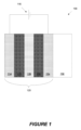
いくつかの実施形態によるエレクトロクロミックデバイス100の概略断面図が、図1示されている。ECデバイスコーティングは、基板102、透明導電層(TCL)104、エレクトロクロミック層(EC)106(カソードカラーリング層またはカソード着色層と呼ばれることもある)、イオン伝導層または領域(IC)108、対電極層(CE)110(アノードカラーリング層またはアノード着色層と呼ばれることもある)、および第2のTCL114に取り付けられる。要素104、106、108、110、および114は、集合的にエレクトロクロミックスタック120と呼ばれる。エレクトロクロミックスタック120の両端間に電位を印加するように動作可能な電圧源116は、例えば、クリア状態から着色状態へのエレクトロクロミックコーティングの遷移をもたらす。他の実施形態では、層の順序は、基板に対して反転される。すなわち、それらの層は、以下の、基板、TCL、対電極層、イオン伝導層、エレクトロクロミック材料層、TCLの順序をなす。
A schematic cross-sectional view of an
様々な実施形態では、イオン導体領域108は、EC層106の一部分から、かつ/またはCE層110の一部分から形成することができる。そのような実施形態では、エレクトロクロミックスタック120は、アノード着色対電極材料(CE層)と直接物理的に接触するカソード着色エレクトロクロミック材料(EC層)を含むように堆積され得る。イオン伝導体領域108(界面領域、またはイオン伝導性の実質的に電子的に絶縁する層または領域と呼ばれることもある)は、この場合に、例えば加熱および/または他の処理ステップを通じて、EC層106とCE層110とが接する場所に形成され得る。特異なイオン導体材料を堆積せずに製造されたエレクトロクロミックデバイスが、2012年5月2日に出願された、「ELECTROCHROMIC DEVICES」と題する米国特許出願第13/462,725号にさらに考察されており、これは、その全体が参照により本明細書に組み込まれる。いくつかの実施形態では、ECデバイスコーティングはまた、1つ以上の受動層などの1つ以上の追加の層を含み得る。例えば、受動層は、特定の光学的性質を向上させるため、湿りを与えるため、または耐擦傷性をもたらすために使用され得る。これらの受動層または他の受動層はまた、ECスタック120を密封するようにも機能し得る。さらに、透明導電層(104および114など)を含む様々な層が、反射防止層または保護酸化物層もしくは窒化物層を用いて処理されることができる。
In various embodiments, the
特定の実施形態では、エレクトロクロミックデバイスは、透明状態と着色状態との間で可逆的に繰り返すように構成されている。クリア状態では、エレクトロクロミック材料106を着色状態にすることができるスタック内の利用可能なイオンが主に対電極110に存在するように、電位がエレクトロクロミックスタック120に印加される。エレクトロクロミックスタックに印加された電位が反転すると、イオンは、イオン伝導層108を横切ってエレクトロクロミック材料106に輸送され、材料を着色状態に入らせる。
In certain embodiments, the electrochromic device is configured to reversibly cycle between a clear state and a colored state. In the clear state, a potential is applied to the
透明状態と着色状態との間の遷移への言及は、非限定的であり、かつ実施され得るエレクトロクロミック遷移の、多くの例の中の一例のみを示唆するにすぎないことを理解されたい。本明細書で特段の指示がない限り、透明-着色遷移への言及が行われるときは常に、対応するデバイスまたはプロセスは、非反射-反射、透明-不透明などの他の光学的状態遷移を包含する。さらに、「クリア」および「ブリーチ」という用語は、例えば、無着色、透明、または半透明である、光学的に中立な状態を指す。なおさらに、本明細書で別段明記しない限り、エレクトロクロミック移行の「色」または「着色」は、いかなる特定の波長または波長範囲にも限定されない。当業者には理解されるように、適切なエレクトロクロミック材料および対電極材料の選択により、関連する光学的遷移が左右される。 It should be understood that references to transitions between clear and colored states are non-limiting and suggest only one example among many examples of electrochromic transitions that may be implemented. Unless otherwise indicated herein, whenever reference is made to a clear-colored transition, the corresponding device or process encompasses other optical state transitions, such as non-reflective-reflective, transparent-opaque, etc. Furthermore, the terms "clear" and "bleach" refer to an optically neutral state, e.g., uncolored, transparent, or translucent. Still further, unless otherwise indicated herein, the "color" or "coloration" of an electrochromic transition is not limited to any particular wavelength or range of wavelengths. As will be appreciated by those skilled in the art, the selection of appropriate electrochromic and counterelectrode materials will determine the associated optical transition.
特定の実施形態では、エレクトロクロミックスタック120を作り上げる材料のすべては、無機、固体(すなわち、固体状態)、または無機でかつ固体の両方である。有機材料は、特に着色された建物の窓のように熱およびUV光にさらされると、経時的に劣化する傾向があるため、無機材料は、長期間機能することができる信頼性の高いエレクトロクロミックスタックの利点を提供する。固体状態の材料はまた、液体状態の材料によくあるように、封じ込めおよび漏れの問題がないという利点を提供する。スタック内の層のうちの任意の1つ以上は、ある程度の量の有機物質を含有し得るが、多くの実装形態では、層のうちの1つ以上は有機物をほとんどまたは全く含有しないことを理解されたい。1つ以上の層に少量であり得る液体にも同じことが言える。また、固体状態の材料が、ゾルゲルまたは化学蒸着を使用する特定のプロセスなどの、液体成分を採用するプロセスによっても、堆積または形成することができることも理解されたい。
In certain embodiments, all of the materials making up the
図2Aおよび2Bは、いくつかの実装形態による、断熱ガラスユニット(「IGU」)200内に具現化された例示的な着色可能な窓の断面図を示す。一般的に言えば、別段述べない限り、「IGU」、「着色可能な窓」、および「光学的に切り替え可能な窓」という用語は、交換可能に使用される。この描述上の決め事は、例えば、それが一般に知れわたっているため、かつ建物内の設置のために提供されるときに、エレクトロクロミックペイン(「ライト」とも呼ばれる)を保持するための基礎構成としてIGUを機能させることが所望され得るため、一般的に使用される。IGUライトまたはペインは、単一基板または2つの基板の一積層等の多基板構成であり得る。IGU、特に、二重または三重ペイン構成を有するものは、他の単一ペイン構成に対していくつかの利点を提供し得、例えば、多重ペイン構成は、単一ペイン構成と比較されたときに、向上した断熱、遮音、環境保護および/または耐久性を提供し得る。多重ペイン構成はまた、例えば、エレクトロクロミックフィルム、ならびに関連付けられた層および導電性相互接続が、多重ペインIGUの内部表面上に形成され、かつIGUの内部容積208内の不活性ガス充填によって保護され得るため、ECDのための向上した保護を提供し得る。不活性ガス充填は、IGUの(熱)絶縁機能の少なくとも一部を提供する。エレクトロクロミックIGUは、熱および光を吸収(または反射)する着色可能なコーティングの効力によって熱遮断能力を付加している。
2A and 2B show cross-sectional views of an exemplary tintable window embodied in an insulated glass unit ("IGU") 200 according to some implementations. Generally speaking, unless otherwise stated, the terms "IGU", "tintable window", and "optically switchable window" are used interchangeably. This descriptive convention is commonly used, for example, because it is commonly known and because it may be desirable for the IGU to function as a base structure to hold electrochromic panes (also called "lights") when provided for installation in a building. The IGU light or pane may be a single substrate or a multi-substrate configuration, such as a stack of two substrates. IGUs, especially those with double or triple pane configurations, may offer several advantages over other single pane configurations, for example, the multi-pane configuration may offer improved thermal insulation, sound insulation, environmental protection, and/or durability when compared to a single pane configuration. A multi-pane configuration may also provide improved protection for the ECD, for example, because the electrochromic film and associated layers and conductive interconnects may be formed on the interior surfaces of the multi-pane IGU and protected by an inert gas fill within the
図2Aは、第1の表面S1および第2の表面S2を有する第1のペイン204を含むIGU200の例示的な実装形態を示す。いくつかの実装形態では、第1のペイン204の第1の表面S1は、戸外または外部環境などの外部環境に面する。IGU200は、第1の表面S3および第2の表面S4を有する第2のペイン206も含む。いくつかの実装形態では、第2のペイン206の第2の表面S4は、家、建物、もしくは車両の内側環境、または家、建物、もしくは車両内の部屋もしくは客室など、屋内環境に面している。
2A illustrates an example implementation of an
いくつかの実装形態において、第1のペイン204および第2のペイン206の各々は、-少なくとも可視スペクトル内の光に対して透明または半透明である。例えば、ペイン204および206の各々は、ガラス材料、特に建築用ガラス、または、例えば、酸化ケイ素(SOx)系ガラス材料などの他の耐破砕性ガラス材料で形成され得る。より具体的な例として、第1のペイン204および第2のペイン206の各々は、ソーダ石灰ガラス基板またはフロートガラス基板とすることができる。このようなガラス基板は、例えば、約75%シリカ(SiO2)とともに、Na2O、CaO、およびいつかの少量の添加剤から構成され得る。しかしながら、第1のペイン204および第2のペイン206の各々は、好適な光学的性質、電気的性質、熱的性質、および機械的性質を有するいずれの材料ででも形成され得る。例えば、第1のペイン204および第2のペイン206のうちの1つまたは両方として使用され得る他の好適な基板には、他のガラス材料とともに、可塑性材料、半可塑性材料、熱可塑性材料(例えば、ポリ(メチルメタクリレート)、ポリスチレン、ポリカーボネート、アリルジグリコールカーボネート、SAN(スチレンアクリロニトリルコポリマー)、ポリ(4-メチル-1-ペンテン)、ポリエステル、ポリアミド)、または鏡材が挙げられ得る。いくつかの実装形態において、例えば、焼き戻し、加熱、またはイオン強化によって、第1のペイン204および第2のペイン206の各々が、強化され得る。
In some implementations, each of the
一般に、第1のペイン204および第2のペイン206の各々、ならびに全体としてのIGU200は、直方体である。しかしながら、いくつかの他の実装形態において他の形状が考えられ、所望され得る(例えば、円形、楕円形、三角形、曲線状、凸または凹形状)。いくつかの具体的な実装形態では、第1のペイン204および第2のペイン206の各々の長さ「L」は、およそ20インチ(in.)~およそ10フィート(ft.)の範囲にあることができ、第1のペイン204および第2のペイン206の各々の幅「W」は、およそ20インチ~およそ10フィートの範囲にあることができ、第1のペイン204および第2のペイン206の各々の厚さ「T」は、およそ0.3ミリメートル(mm)~およそ10mmの範囲にあることができる(ただし、より小さいおよびより大きい、他の長さ、幅、または厚さが、可能であり、特定のユーザ、管理人、管理者、建築者、設計者、または所有者の要求に基づいて望ましい場合がある)。基板204の厚さTが3mm未満である例において、通常、基板は、より厚く、かつしたがって薄い基板204を保護する、追加の基板に積層される。さらに、IGU200は、2つのペイン(204および206)を含むが、いくつかの他の実装形態では、IGUは、3つ以上のペインを含むことができる。さらに、いくつかの実装形態において、ペインのうちの1つ以上は、それ自体、2つ、3つ以上の層またはサブペインの積層構造とすることができる。
Generally, each of the
第1のペイン204および第2のペイン206は、スペーサ218によって互いに離間され、そのスペーサは、通常、フレーム構造であり、内部容積208を形成する。いくつかの実装形態において、内部容積は、アルゴン(Ar)で充填されるが、いくつかの他の実装形態においては、内部容積108は、別の希ガス(例えば、クリプトン(Kr)またはキセノン(Xe))、別のガス(非希ガス)、またはガスの混合物(例えば、空気)など、別のガスで充填することができる。内部容積208をAr、Kr、またはXeなどのガスで充填することにより、これらのガスの低熱伝導率によって、IGU200を通る伝導性熱伝達を低減することができ、ならびにそれらの原子量が大きいことに起因して防音を高めることができる。いくつかの他の実装形態では、内部容積208から、空気または他の気体を取り除いて空にすることができる。スペーサ218は、概して、内部容積208、つまり、第1のペイン204と第2のペイン206との間の空間の高さ「C」を決定する。図2Aにおいて、ECD、シーリング材220/222、およびバスバー226/228の厚さは、縮尺通りではなく、これらの構成要素は、通常、極めて薄いが、説明の容易さのみのために、ここでは誇張されている。いくつかの実装形態において、第1のペイン204と第2のペイン206との間の間隔「C」は、約6mm~約30mmの範囲である。スペーサ218の幅「D」は、約5mm~約25mmの範囲であり得る(ただし、他の幅も、可能性があり、望ましい場合がある)。
The
その断面図には示されていないが、スペーサ218は、一般に、IGU200のすべての側面(例えば、IGU200の上部、底部、左側、および右側)の周りに形成されたフレーム構造である。例えば、スペーサ218は、発泡体またはプラスチック材料から形成され得る。しかしながら、いくつかの他の実装形態において、スペーサは、金属または他の導電性材料、例えば、基板の各々に対するシールのための2つの側部、ならびにライトを支持および分離し、シーリング材224を塗布する表面としての1つの側部の少なくとも3つの側部を有する金属管または溝構造から形成され得る。第1の一次シール220は、スペーサ218と第1のペイン204の第2の表面S2とを接着および密封する。第2の一次シール222は、スペーサ218と第2のペイン206の第1の表面S3とを接着および密封する。実装形態によっては、一次シール220および222の各々は、例えばポリイソブチレン(PIB)などの接着シーリング材で形成され得る。いくつかの実装形態において、IGU200は、スペーサ218の外側のIGU200全体の周囲の境界を密封する二次シール224をさらに含む。この目的で、スペーサ218は、第1のペイン204および第2のペイン206の縁端部から距離「E」のところにはめ込まれている。距離「E」は、およそ4mm~およそ8mmの範囲内にあり得る(ただし、他の距離が、可能であり、望ましい場合がある)。いくつかの実装形態において、二次シール224が、例えば、耐水性があり、かつシリコーン、ポリウレタン、および防水シールを形成する同様の構造シーリング材などの、アセンブリに構造支持部を付加するポリマー材料などの接着シーリング材で形成することができる。
Although not shown in the cross-sectional view, the
図2Aに示された実装形態において、ECD210が、第1のペイン204の第2の表面S2上に形成されている。いくつかの他の実装形態において、ECD210は、別の好適な表面、例えば、第1のペイン204の第1の表面S1、第2のペイン206の第1の表面S3または第2のペイン206の第2の表面S4上に形成され得る。ECD210は、エレクトロクロミック(「EC」)スタック212を含み、そのエレクトロクロミックスタック自体が、図1を参照して説明されたように、1つ以上の層を含むことができる。
In the implementation shown in FIG. 2A, the
窓コントローラ
窓コントローラは、1つ以上の着色可能な窓と関連付けられ得、刺激を窓に加えることによって、-例えば、電圧または電流をECデバイスコーティングに印加することによって、窓の光学的状態を制御するように構成される。本明細書に記載の窓コントローラは、それらが制御する光学的に切り替え可能な窓に関して、多くのサイズ、形式、および位置を有することができる。通常、コントローラは、IGUまたは積層のライトに取り付けることができるが、そのコントローラはまた、IGUもしくは積層を収容するフレーム内、またはさらには別個の場所に存在する場合もある。前述したように、着色可能な窓は、1つ、2つ、3つ以上の個々のエレクトロクロミックペイン(透明基板上のエレクトロクロミックデバイス)を含み得る。また、エレクトロクロミック窓の個々のペインは、独立して着色可能なゾーンを有するエレクトロクロミックコーティングを有することができる。本明細書に記載されているようなコントローラは、エレクトロクロミックコーティングが一体構造であるかまたは層状配列かどうかにかかわらず、このような窓と関連付けられたすべてのエレクトロクロミックコーティングを制御することができる。
Window Controllers A window controller may be associated with one or more tintable windows and is configured to control the optical state of the window by applying a stimulus to the window - for example, by applying a voltage or current to the EC device coating. Window controllers described herein can have many sizes, formats, and locations with respect to the optically switchable windows they control. Typically, the controller can be attached to the IGU or light stack, but the controller may also be in a frame housing the IGU or stack, or even in a separate location. As previously mentioned, tintable windows can include one, two, three, or more individual electrochromic panes (electrochromic devices on a transparent substrate). Also, the individual panes of an electrochromic window can have an electrochromic coating with independently tintable zones. A controller as described herein can control all electrochromic coatings associated with such windows, regardless of whether the electrochromic coating is a monolithic structure or a layered arrangement.
着色可能な窓、IGU、またはフレームに直接取り付けられない場合、窓コントローラは、通常、着色可能な窓の近傍に配置される。例えば、窓コントローラは、窓に隣接し得るか、窓のライトのうちの1つの表面上にあり得るか、窓の隣の壁内にあり得るか、または自己完結型の窓アセンブリのフレーム内にあり得る。いくつかの実施形態では、窓コントローラは「原位置(in situ)」コントローラである。すなわち、コントローラは、窓アセンブリ、IGUまたはラミネートの一部であり、エレクトロクロミック窓と一致させる、および現場で設置される必要はなくてもよく、例えば、コントローラは、工場からアセンブリの一部として窓とともに移動する。コントローラは、窓アセンブリの窓フレーム内に設置されてもよく、または、例えばIGUのペイン上または間に、あるいはラミネートのペイン上に取り付けられたIGUまたはラミネートアセンブリの一部であってもよい。コントローラがIGUの可視部分に位置する場合、コントローラの少なくとも一部分は、実質的に透明であり得る。ガラス上のコントローラに関するさらなる例が、2015年11月14日に出願された「SELF CONTAINED EC IGU」と題する米国特許出願第14/951,410号に提供されており、これは、その全体が参照により本明細書に組み込まれる。いくつかの実施形態では、局在したコントローラが、複数の部分として提供されることができ、少なくとも1つの部分(例えば、関連付けられたエレクトロクロミック窓に関する情報を記憶するメモリコンポーネント)が、窓アセンブリの一部として提供され、および少なくとも1つの他の部分が、離隔し、かつ窓アセンブリ、IGU、またはラミネートの一部である少なくとも1つの部分と嵌合するように構成される。特定の実施形態では、コントローラは、単一のハウジング内にはなく、むしろ例えば、IGUの二次シール内に離間する、相互接続された部分のアセンブリであり得る。他の実施形態では、コントローラは、例えば、単一のハウジング内、または例えば、ドックおよびハウジングアセンブリを組み合わせた2つ以上の構成要素内にあるコンパクトユニットであり、そのコンパクトユニットは、可視領域内ではなくガラスに近接するか、または可視領域内のガラス上に取り付けられる。 If not directly attached to the tintable window, IGU, or frame, the window controller is typically located in the vicinity of the tintable window. For example, the window controller may be adjacent to the window, on the surface of one of the window lights, in a wall next to the window, or in the frame of a self-contained window assembly. In some embodiments, the window controller is an "in situ" controller. That is, the controller is part of the window assembly, IGU, or laminate, and may not need to be matched with the electrochromic window and installed on-site, e.g., the controller travels with the window from a factory as part of the assembly. The controller may be installed in the window frame of the window assembly, or may be part of the IGU or laminate assembly, for example, mounted on or between the panes of the IGU or on the panes of the laminate. If the controller is located in a visible portion of the IGU, at least a portion of the controller may be substantially transparent. Further examples of controllers on glass are provided in U.S. Patent Application No. 14/951,410, entitled "SELF CONTAINED EC IGU," filed November 14, 2015, which is incorporated herein by reference in its entirety. In some embodiments, a localized controller can be provided as multiple parts, with at least one part (e.g., a memory component that stores information about an associated electrochromic window) provided as part of the window assembly, and at least one other part configured to space and mate with at least one part that is part of the window assembly, IGU, or laminate. In certain embodiments, the controller is not in a single housing, but rather an assembly of interconnected parts that are spaced apart, for example, in the secondary seal of an IGU. In other embodiments, the controller is a compact unit, for example, in a single housing, or in two or more components that combine, for example, a dock and housing assembly, that is mounted adjacent to the glass but not in the visible area, or on the glass in the visible area.
一実施形態では、窓コントローラは、着色可能な窓の設置前に、IGUおよび/もしくは窓フレームの中もしくは上に、または少なくとも窓と同じ建物内に組み込まれる。一実施形態では、コントローラは、製造施設を離れる前に、IGUおよび/または窓フレームの中またはその上に組み込まれる。一実施形態では、コントローラは、実質的に二次シール内でIGU中に組み込まれる。別の実施形態では、コントローラは、IGUの中または上に、シーリングセパレータと基板との間の一次シールによって画定された外周部内に、部分的に、実質的に、または全体的に組み込まれる。 In one embodiment, the window controller is installed in or on the IGU and/or window frame, or at least in the same building as the window, prior to installation of the tintable window. In one embodiment, the controller is installed in or on the IGU and/or window frame prior to leaving the manufacturing facility. In one embodiment, the controller is installed in the IGU substantially within the secondary seal. In another embodiment, the controller is installed partially, substantially, or entirely in or on the IGU within the perimeter defined by the primary seal between the sealing separator and the substrate.
コントローラは、IGUおよび/または窓アセンブリの一部であってもよく、例えば、IGUまたは窓ユニットとともに移動してもよい。コントローラがIGUアセンブリの一部である場合、IGUは、コントローラのロジックおよび特徴を保有することができる。 The controller may be part of the IGU and/or window assembly, for example, may move with the IGU or window unit. If the controller is part of the IGU assembly, the IGU may retain the logic and features of the controller.
エレクトロクロミックデバイスの特性が時間の経過とともに変化する(例えば、劣化によって)という事象において、特性関数を使用して、例えば、着色状態遷移を推進するために使用される制御パラメータを更新することができる。別の例において、エレクトロクロミック窓ユニット内に既に設置されている場合、コントローラのロジックおよび特徴を使用して、制御パラメータを較正し、企図された設置に整合させることができ、例えば、既に設置されている場合、制御パラメータを再較正して、エレクトロクロミックペインの性能特性に整合させることができる。 In the event that the characteristics of the electrochromic device change over time (e.g., due to degradation), the characteristic function can be used to, for example, update the control parameters used to drive the coloration state transitions. In another example, once already installed in an electrochromic window unit, the logic and features of the controller can be used to calibrate the control parameters to match the intended installation, e.g., once already installed, the control parameters can be recalibrated to match the performance characteristics of the electrochromic pane.
他の実施形態では、コントローラは、窓と事前に関連付けられるのではなく、例えば、任意のエレクトロクロミック窓に汎用性のあるパーツを有するドックコンポーネントが、工場で各窓と関連付けられる。窓の設置後、または他の分野では、コントローラの第2のコンポーネントがドックコンポーネントと組み合わされて、エレクトロクロミック窓コントローラアセンブリが完成する。ドックコンポーネントは、ドックが取り付けられる(例えば、設置後に建物の内部に面し、時には表面4または「S4」と呼ばれる表面上に)特定の窓の物理的特性およびパラメータで工場でプログラムされるチップを含み得る。第2のコンポーネント(時には「キャリア」、「ケーシング」、「ハウジング」、または「コントローラ」とも呼ばれる)はドックと嵌め合い、電力が供給されると、第2のコンポーネントは、チップを読み取り、チップに記憶された特定の特性およびパラメータに従って、窓に電力を供給するようにそれ自体を構成することができる。このようにして、出荷された窓は、窓と一体となるチップに記憶されたその関連パラメータを有するだけでよく、一方でより洗練された回路およびコンポーネントは、後で組み合わせることができる(例えば、別々に出荷され、ガラス工が窓を取り付けた後に窓製造業者によって取り付けられ、続いて窓製造業者によるコミッショニングが行われる)。様々な実施形態を以下により詳細に説明する。いくつかの実施形態では、チップは、窓コントローラに取り付けられたワイヤまたはワイヤコネクタに含まれる。このようなコネクタ付きワイヤは、ときにはリード線と呼ばれることがある。
In other embodiments, the controller is not pre-associated with the window, but rather a dock component, for example, with parts that are generic to any electrochromic window, is associated with each window at the factory. After installation of the window, or in other fields, a second component of the controller is combined with the dock component to complete the electrochromic window controller assembly. The dock component may include a chip that is programmed at the factory with the physical characteristics and parameters of the particular window to which the dock is attached (e.g., on the surface that faces the interior of the building after installation, sometimes referred to as
考察されたように、「IGU」は、2つの(またはそれを上回る)実質的に透明な基板、例えば、2つのガラスのペインを含み、その場合、少なくとも1つの基板が、その上に配設されたエレクトロクロミックデバイスを含み、それらのペインは、それらの間に配設されたセパレータを有する。IGUは通常密封封止され、周囲環境から隔離された内部領域を有する。「窓アセンブリ」は、IGUまたは例えば、独立型ラミネートを含むことができ、IGUまたはラミネート1つ以上のエレクトロクロミックデバイスを電圧源、スイッチなどに接続するための電気リードを含み、IGUまたはラミネートを支持するフレームを含み得る。窓アセンブリは、本明細書に記載されているような窓コントローラ、および/または窓コントローラの構成要素(例えば、ドック)を含むことができる。 As discussed, an "IGU" includes two (or more) substantially transparent substrates, e.g., two panes of glass, where at least one substrate includes an electrochromic device disposed thereon, and the panes have a separator disposed therebetween. An IGU is typically hermetically sealed and has an interior area isolated from the surrounding environment. A "window assembly" can include an IGU or, for example, a stand-alone laminate, and can include electrical leads for connecting the IGU or laminate one or more electrochromic devices to a voltage source, switch, etc., and can include a frame to support the IGU or laminate. A window assembly can include a window controller as described herein, and/or components of a window controller (e.g., a dock).
本明細書で使用されるとき、アウトボードという用語は、外部環境により近いことを意味し、一方で、インボードという用語は、建物の屋内により近いことを意味する。例えば、2つのペインを有するIGUの場合、外部環境の近くに置かれるペインは、アウトボードペインまたは外側ペインと呼ばれ、一方で建物の内部の近くに置かれるペインは、インボードペインまたは内側ペインと呼ばれる。図2Aおよび2Bに関して例示されているように、IGUの異なる表面は、S1、S2、S3、およびS4(2つのペインのIGUを想定)と呼ぶことができる。S1は、アウトボードライトの外側に面する表面(すなわち、外に立っている人が物理的に触れることができる表面)を指す。S2は、アウトボードライトの内側に面する表面を指す。S3は、インボードライトの外側に面する表面を指す。S4は、インボードライトの内側に面する表面(すなわち、建物の中に立っている人が物理的に触れることができる表面)を指す。言い換えれば、表面は、IGUの最も外側の表面から内側に向かって数えて、S1~S4というラベルが付けられる。IGUが3つのペインを含む場合、この傾向は、成り立つ(S6は、建物の内側に立っている人によって物理的に触ることができる表面である)。2枚のペインを用いる特定の実施形態では、エレクトロクロミックデバイス(または他の光学的に切り替え可能なデバイス)はS3上に配置される。特定の実施形態では、表面のうちの1つ以上が、電磁放射の透過を遮断するための構造を有する。図2Bにおいて、これは、S3上の「IMI」(複数の導電層のシールドスタック)として例示されている。シールドスタック構造の追加の態様が、2017年9月19日に出願された米国特許出願第15/709,339号に提示されており、これは、その全体が参照により本明細書に組み込まれる。 As used herein, the term outboard means closer to the outside environment, while the term inboard means closer to the interior of a building. For example, in the case of an IGU having two panes, the pane placed closer to the outside environment is called the outboard pane or outer pane, while the pane placed closer to the interior of the building is called the inboard pane or inner pane. As illustrated with respect to FIGS. 2A and 2B, the different surfaces of the IGU can be called S1, S2, S3, and S4 (assuming a two-pane IGU). S1 refers to the outboard facing surface of the outboard light (i.e., the surface that can be physically touched by a person standing outside). S2 refers to the inboard facing surface of the outboard light. S3 refers to the outboard facing surface of the inboard light. S4 refers to the inboard facing surface of the inboard light (i.e., the surface that can be physically touched by a person standing inside the building). In other words, the surfaces are labeled S1-S4, counting inward from the outermost surface of the IGU. This trend holds true when the IGU includes three panes (S6 is the surface that can be physically touched by a person standing inside the building). In certain embodiments with two panes, the electrochromic device (or other optically switchable device) is placed on S3. In certain embodiments, one or more of the surfaces has a structure for blocking the transmission of electromagnetic radiation. In FIG. 2B, this is illustrated as an "IMI" (multiple conductive layer shield stack) on S3. Additional aspects of the shield stack structure are presented in U.S. Patent Application Serial No. 15/709,339, filed September 19, 2017, which is incorporated herein by reference in its entirety.
窓コントローラおよびそれらの特徴のさらなる例が、2012年4月17日に出願された「CONTROLLER FOR OPTICALLY-SWITCHABLE WINDOWS」と題する米国特許出願第13/449,248号、2012年4月17日に出願された「CONTROLLER FOR OPTICALLY-SWITCHABLE WINDOWS」と題する米国特許出願第13/449,251号、2016年10月26日に出願された「CONTROLLERS FOR OPTICALLY-SWITCHABLE DEVICES」と題する米国特許出願第15/334,835号、および2017年3月3日に出願された「METHOD OF COMMISSIONING ELECTROCHROMIC WINDOWS」と題する国際特許出願第PCT/US17/20805号に提示されており、これらの各々は、その全体が参照により本明細書に組み込まれる。 Further examples of window controllers and their features are described in U.S. patent application Ser. No. 13/449,248, filed April 17, 2012, entitled "CONTROLLER FOR OPTICALLY-SWITCHABLE WINDOWS," U.S. patent application Ser. No. 13/449,251, filed April 17, 2012, entitled "CONTROLLER FOR OPTICALLY-SWITCHABLE WINDOWS," U.S. patent application Ser. No. 13/449,251, filed October 26, 2016, entitled "CONTROLLERS FOR OPTICALLY-SWITCHABLE WINDOWS," U.S. patent application Ser. No. 13/449,251, filed October 26, 2016, entitled "CONTROLLERS FOR OPTICALLY-SWITCHABLE WINDOWS," U.S. patent application Ser. No. 15/334,835, entitled "METHOD OF COMMISSIONING ELECTROCHROMIC DEVICES," and International Patent Application No. PCT/US17/20805, filed March 3, 2017, entitled "METHOD OF COMMISSIONING ELECTROCHROMIC WINDOWS," each of which is incorporated herein by reference in its entirety.
窓制御システム
建物が着色可能な窓で装備されると、窓コントローラは、窓制御ネットワークまたは窓ネットワークと呼ばれることがある通信ネットワークを介して、互いにかつ/または他のエンティティに接続することができる。ネットワーク(例えば、有線または無線の電力転送および/または通信)を介して接続されるネットワークおよび様々なデバイス(例えば、コントローラおよびセンサ)は、本明細書において、窓制御システムと称される。窓制御ネットワークは、着色命令を窓コントローラに提供すること、窓情報をマスターコントローラまたは他のネットワークエンティティなどに提供することができる。窓情報の例としては、窓コントローラによって収集された現在の着色状態または他の情報が挙げられる。いくつかの場合、窓コントローラは、例えば、フォトセンサ、温度センサ、占有センサ、および/またはガスセンサを含む、検知した情報をネットワークを介して提供する1つ以上の関連付けられたセンサを有する。いくつかの場合、窓通信ネットワークを介して伝送される情報は、必ずしも窓制御に影響を与えない。例えば、Wi-Fi(登録商標)またはLiFi信号を受信するように構成された第1の窓で受信した情報は、通信ネットワークを介して、例えば、Wi-Fi(登録商標)またはLiFi信号として情報を無線でブロードキャストするように構成された第2の窓に送信することができる。窓制御ネットワークは、必ずしも着色可能な窓を制御するための情報を提供することに限定される必要がなく、HVACシステム、照明システム、セキュリティシステム、パーソナルコンピューティングデバイスなどの、通信ネットワークとインターフェース接続する他のデバイスのための情報を伝達することもできる。
Window Control System When a building is equipped with tintable windows, the window controllers can be connected to each other and/or other entities via a communication network, sometimes referred to as a window control network or window network. The network and various devices (e.g., controllers and sensors) connected via the network (e.g., wired or wireless power transfer and/or communication) are referred to herein as a window control system. The window control network can provide tinting instructions to the window controllers, provide window information to a master controller or other network entity, and the like. Examples of window information include current tinting status or other information collected by the window controllers. In some cases, the window controller has one or more associated sensors that provide sensed information over the network, including, for example, photo sensors, temperature sensors, occupancy sensors, and/or gas sensors. In some cases, information transmitted over a window communication network does not necessarily affect window control. For example, information received at a first window configured to receive Wi-Fi or LiFi signals can be transmitted over the communication network to a second window configured to wirelessly broadcast information, for example, as a Wi-Fi or LiFi signal. The window control network does not necessarily need to be limited to providing information for controlling tintable windows, but may also convey information for other devices that interface with the communications network, such as HVAC systems, lighting systems, security systems, personal computing devices, etc.
図3は、窓制御システム300の制御ネットワーク301の一例を提供する。ネットワークは、制御命令およびフィードバックを配信すること、ならびに配電ネットワークとしての役割を果たすことができる。マスターコントローラ302は、多数のネットワークコントローラ304と通信し、かつそれらと連動して機能し、ネットワークコントローラの各々は、1つ以上の光学的に切り換え可能な窓308の着色状態を制御するために電圧または電流を印加する、複数の窓コントローラ306(本明細書において、リーフコントローラと称されることがある)をアドレッシングすることができる。通信コントローラ(304、306、および308)は、有線(例えば、イーサネット(登録商標))を介して、または無線(例えば、Wi-Fi(登録商標)、CBRS、セルラー、またはLiFi)接続を介して、存在し得る。いくつかの実装形態において、マスターコントローラは、ネットワークコントローラに高レベル命令(エレクトロクロミック窓の最終的な着色状態など)を出し、次いで、ネットワークコントローラは、対応する窓コントローラに命令を通信する。典型的に、マスターコントローラは、1つ以上の外向きネットワーク309と通信するように構成される。窓制御ネットワーク301は、様々な能力または機能を有する任意の好適な数の分散コントローラを含むことができ、必ずしも図3に描示される階層構造内に配置されない。ネットワーク301はまた、他のデバイスまたはシステム(例えば、309)への通信ノードとして作用する分散コントローラ(例えば、302、304、306)間の通信ネットワークとして使用することもできる。 3 provides an example of a control network 301 of a window control system 300. The network can distribute control commands and feedback as well as act as a power distribution network. A master controller 302 communicates with and works in conjunction with multiple network controllers 304, each of which can address multiple window controllers 306 (sometimes referred to herein as leaf controllers) that apply voltage or current to control the coloration state of one or more optically switchable windows 308. The communication controllers (304, 306, and 308) can be via wired (e.g., Ethernet) or wireless (e.g., Wi-Fi, CBRS, cellular, or LiFi) connections. In some implementations, the master controller issues high-level commands (such as the final coloration state of an electrochromic window) to the network controllers, which then communicate the commands to the corresponding window controllers. Typically, the master controller is configured to communicate with one or more outbound networks 309. The window control network 301 can include any suitable number of distributed controllers having various capabilities or functions, and are not necessarily arranged in the hierarchical structure depicted in FIG. 3. The network 301 can also be used as a communication network between the distributed controllers (e.g., 302, 304, 306) that act as communication nodes to other devices or systems (e.g., 309).
いくつかの実施形態において、外側に面するネットワーク309は、建物管理システム(BMS)の一部であるか、またはそれに接続される。BMSは、建物の機械設備および電気設備を監視および制御するために建物内に設置することができる、コンピュータベースの制御システムである。BMSは、HVACシステム、照明システム、電力システム、エレベータ、火災システム、セキュリティシステム、他の安全システムの動作を制御するように構成することができる。BMSは、大きな建物内で頻繁に使用され、建物内の環境を制御するように機能する。例えば、BMSは、建物内の照明、温度、二酸化炭素レベル、および湿度を監視および制御することができる。その際に、BMSは、暖房炉、空調装置、送風機、通気口、ガスライン、水道ラインなどの動作を制御することができる。建物の環境を制御するために、BMSは、例えば建物管理者によって確立されたルールに従って、これらの様々なデバイスをオンおよびオフにすることができる。BMSの1つの機能は、建物入居者のために快適な環境を維持することである。いくつかの実装形態において、BMSは、建物状態を監視および制御するだけでなく、様々なシステム間の相乗効果も最適化する-例えば、エネルギーを節約し、建物運営コストを低減するように構成することもできる。いくつかの実装形態において、BMSは、災害応答を用いて構成され得る。例えば、BMSは、バックアップの発電機の使用を開始し、かつ水道ラインおよびガスラインをオフにすることができる。場合によっては、BMSは、より焦点を絞った用途、-例えば、HVACシステムを単純に制御すること-を有し、一方では、照明、着色可能な窓、および/またはセキュリティシステムなどの並列システムが、スタンドアロンで動作するか、またはBMSと相互作用する。 In some embodiments, the outward-facing network 309 is part of or connected to a building management system (BMS). A BMS is a computer-based control system that can be installed in a building to monitor and control the building's mechanical and electrical equipment. The BMS can be configured to control the operation of HVAC systems, lighting systems, power systems, elevators, fire systems, security systems, and other safety systems. BMSs are frequently used in large buildings and function to control the environment within the building. For example, the BMS can monitor and control the lighting, temperature, carbon dioxide levels, and humidity within the building. In doing so, the BMS can control the operation of furnaces, air conditioners, fans, vents, gas lines, water lines, and the like. To control the building's environment, the BMS can turn these various devices on and off according to rules established, for example, by the building manager. One function of the BMS is to maintain a comfortable environment for the building occupants. In some implementations, the BMS not only monitors and controls building conditions, but can also be configured to optimize synergies between various systems - for example, to save energy and reduce building operating costs. In some implementations, the BMS can be configured with disaster response - for example, the BMS can initiate use of backup generators and turn off water and gas lines. In some cases, the BMS has a more focused application - for example, simply controlling the HVAC system - while parallel systems such as lighting, tintable windows, and/or security systems operate standalone or interact with the BMS.
いくつかの実施形態において、ネットワーク309は、リモートネットワークである。例えば、ネットワーク309は、クラウドにおいて、または光学的に切り換え可能な窓を有する建物から離れたデバイス上で動作することができる。いくつかの実施形態において、ネットワーク309は、情報を提供するか、またはリモート無線デバイスを介して、光学的に切り換え可能な窓の制御を可能にするネットワークである。いくつかの場合、ネットワーク309は、地震事象検出ロジックを含む。窓制御システムおよびそれらの特徴のさらなる例が、2016年10月26日に出願された「CONTROLLERS FOR OPTICALLY-SWITCHABLE DEVICES」と題する米国特許出願第15/334,832号、および2016年11月23日に出願された「AUTOMATED COMMISSIONING OF CONTROLLERS IN A WINDOW NETWORK」と題する国際特許出願第PCT/US17/62634号に提示されており、これらの両方は、その全体が参照により本明細書に組み込まれる。 In some embodiments, network 309 is a remote network. For example, network 309 can operate in the cloud or on a device remote from the building having the optically switchable windows. In some embodiments, network 309 is a network that provides information or enables control of the optically switchable windows via a remote wireless device. In some cases, network 309 includes earthquake event detection logic. Further examples of window control systems and their features are presented in U.S. Patent Application No. 15/334,832, entitled "CONTROLLERS FOR OPTICALLY-SWITCHABLE DEVICES," filed October 26, 2016, and International Patent Application No. PCT/US17/62634, entitled "AUTOMATED COMMISSIONING OF CONTROLLERS IN A WINDOW NETWORK," filed November 23, 2016, both of which are incorporated herein by reference in their entireties.
図示された実施形態は、窓308および窓制御ネットワーク301を示しているが、いくつかの実施形態がEC窓、または光学的に切り替え可能な他のいずれのタイプの窓も含まないことを理解されたい。さらに、特定の実施形態では、ネットワークは、コントローラを含むが、コントローラは、窓を制御しない。いくつかの実施形態では、ネットワークは、図3に描示されているものと同様のトポロジーを有するが、それは必ずしも窓を制御することに役立つとは限らない。そのようなネットワークは、様々な他の目的に役立つことができ、光学的に切り替え可能な窓の着色状態または他の建物機能を制御するための命令を提供することを含む場合も含まない場合もある。いくつかの場合、ネットワークは、初期に、光学的に切り替え可能な窓なしで展開されるが、後でそのような窓が設置され、ネットワークに取り付けられる。窓取り付けの有無にかかわらず、ネットワークは、窓制御とは関係のない様々な機能を提供することができる。例えば、特定の実施形態では、切り替え可能な窓の有無にかかわらず、建物正面外壁(包絡面)コンピューティングおよび配電システムが、記載されている。このようなシステムは、建物の建設の初期に設置することができ、したがって、建物の建設が完了してその建物が占有されると、例えば、建設を完了するために使用することができ、かつ/または建物入居者が使用することができるエッジコンピューティングプラットフォームおよび/またはクラウドに、電力および計算能力を供給することができる。例えば、2019年5月2日に出願されたPCT特許出願第PCT/US19/30467号の考察を参照され、これは、その全体が参照により本明細書に組み込まれる。 While the illustrated embodiment shows windows 308 and a window control network 301, it should be understood that some embodiments do not include EC windows, or any other type of optically switchable window. Furthermore, in certain embodiments, the network includes a controller, but the controller does not control the window. In some embodiments, the network has a topology similar to that depicted in FIG. 3, but it does not necessarily serve to control the window. Such a network can serve a variety of other purposes, which may or may not include providing instructions to control the tint state of optically switchable windows or other building functions. In some cases, the network is initially deployed without optically switchable windows, but such windows are later installed and attached to the network. With or without window attachment, the network can provide various functions unrelated to window control. For example, in certain embodiments, a building facade (envelope) computing and power distribution system is described, with or without switchable windows. Such a system can be installed early in the construction of a building, and thus, once construction of the building is completed and the building is occupied, can provide power and computing power to an edge computing platform and/or cloud that can be used, for example, to complete construction and/or be used by building occupants. See, for example, the discussion in PCT Patent Application No. PCT/US19/30467, filed May 2, 2019, which is incorporated herein by reference in its entirety.
本明細書に開示された通信インフラストラクチャは、光学的に切り替え可能な窓を提供する場合、または提供しない場合があり得ることを理解されたい。後者の場合、すなわち、窓インフラストラクチャを有さない場合、ネットワークは、電気的に切り替え可能な窓に接続され、窓コントローラを含み、かつ/または窓の適切な光学状態を決定するためのロジックを有する必要はない。 It should be understood that the communications infrastructure disclosed herein may or may not provide optically switchable windows. In the latter case, i.e., without a window infrastructure, the network need not be connected to electrically switchable windows, include a window controller, and/or have logic for determining the appropriate optical state of the window.
通信インフラストラクチャ構成要素
建物ネットワークインフラストラクチャには、通常、無線信号を受信および/または送信するためのアンテナ、アンテナとケーブルとの間で情報を結合するための高速スイッチまたは他のネットワークデバイス、およびアンテナ間で情報を搬送するのための大容量回線などの様々な構成要素が含まれる。
Communications Infrastructure Components A building network infrastructure typically includes various components such as antennas for receiving and/or transmitting radio signals, high-speed switches or other network devices for coupling information between the antennas and cables, and high-capacity lines for carrying information between the antennas.
大容量ケーブル、ツイストペア電線、または他のデータ搬送回線を採用することができる。特定の実施形態では、このような回線は、少なくとも1ギガビット/秒のイーサネット(登録商標)通信、または少なくとも10ギガビット/秒のイーサネット(登録商標)通信を搬送するように構成されている。特定の実施形態では、このような回線は、2019年2月8日に出願された米国仮特許出願第62/803,324号に記載されているように、MoCA回路に結合された同軸ケーブルであり、その全体が参照により本明細書に以前に組み込まれている。 High capacity cables, twisted pair wires, or other data carrying lines may be employed. In certain embodiments, such lines are configured to carry at least 1 Gigabit/sec Ethernet communications, or at least 10 Gigabit/sec Ethernet communications. In certain embodiments, such lines are coaxial cables coupled to MoCA circuits, as described in U.S. Provisional Patent Application No. 62/803,324, filed February 8, 2019, previously incorporated herein by reference in its entirety.
アンテナに関して、これらのうちのいくつかは、建物の屋内に面する場合がある(例えば、それらのアンテナは、部屋または建物の他の内部の部分の方向に電磁信号を送信および/または受信するように位置決めおよび方向付けられる)。場合によっては、1つ以上のアンテナが、建物の屋内から離れて外側へ面する。そのようなアンテナは、建物の外側で電磁信号(例えば、セルラー信号)を送信および/または受信するように位置決めおよび方向付けられ得る。依然として、他のアンテナは、全方向性であってもよく、またはほぼ全方向性であってもよい。 With respect to antennas, some of these may face the interior of the building (e.g., they are positioned and oriented to transmit and/or receive electromagnetic signals in the direction of a room or other interior portion of the building). In some cases, one or more antennas face the exterior, away from the interior of the building. Such antennas may be positioned and oriented to transmit and/or receive electromagnetic signals (e.g., cellular signals) outside the building. Still, other antennas may be omnidirectional or near omnidirectional.
ネットワークインフラストラクチャは、アンテナと連携する1つ以上の無線機を含むことができる。建物内で採用される様々な通信プロトコルには、様々な無線機が、採用され得る。それらの無線機には、様々なベンダーからの無線周波数(RF)無線機チップセットが含まれ得る。無線機は、アンテナから無線信号を受信し、MoCAなどの適切なフォーマットで通信するケーブルに電気信号を提供するための1つ以上の回路を採用することができる(例えば、カリフォルニア州カールズバッドにあるMaxlinear社から販売されているMoCA送受信機デバイスを参照)。 The network infrastructure may include one or more radios in conjunction with antennas. Different radios may be employed for different communication protocols employed within the building. These radios may include radio frequency (RF) radio chipsets from different vendors. The radios may employ one or more circuits for receiving radio signals from the antenna and providing electrical signals to a cable that communicates in an appropriate format, such as MoCA (see, for example, MoCA transceiver devices available from Maxlinear, Inc., Carlsbad, Calif.).
本明細書に記載されているネットワークインフラストラクチャは、建物入居者および建物自体によって提供される様々なデバイスにサービスを提供することができる。一般に、インフラストラクチャは、通信を使用する任意のデバイスにサービスを提供することができる。例としては、携帯電話、タブレット、インターネットオブシングス(IoT)デバイス、センサ、コンピュータ、ディスプレイなどが挙げられる。 The network infrastructure described herein can provide services to a variety of devices provided by building occupants and the building itself. In general, the infrastructure can provide services to any device that uses communications. Examples include mobile phones, tablets, Internet of Things (IoT) devices, sensors, computers, displays, etc.
場合によっては、建物ネットワークインフラストラクチャは、建物の外側に受信機アンテナ、および建物の内側に1つ以上の再送信機アンテナを有することによって、制御された転送を提供する。ただし、建物がより広い地理的セルラー通信インフラストラクチャと連携して働く場合には、その建物は、建物の外側に1つ以上の送信機アンテナ、ならびに建物の内側および/または外側に受信機アンテナを有する場合がある。特定の実施形態では、例えば、建物の屋根の上に配設された屋外アンテナが、4Gまたは5G通信などのセルラー通信とインターフェース接続するように構成される。そのようなアンテナは、2016年10月6日に出願された米国特許出願第15/287,646号などに記載されているように、1つ以上の空気または気象センサを有するスカイセンサまたはリングセンサと一体化または一緒に用いられ得、その全体が、参照により本明細書に組み込まれる。特定の実施形態では、スカイセンサまたはリングセンサには、複数の空気センサ、放射線センサ(例えば、赤外線センサおよび/または可視スペクトル光センサ)などの環境センサ、または他のタイプのセンサが含まれる。いくつかの実施形態では、それらのセンサのうちの1つ以上が、方向付けまたは構成されて、建物における気象を判定および/または予測するための情報を取り込む。例えば、光センサおよび/または赤外線センサを使用して、雲の状態(例えば、タイプ、場所、および雲量の数量)、温度、放射束などを判定することができる。これらのパラメータのいずれも、時間の経過とともに、かつ/または複数の方向で監視され得る。 In some cases, the building network infrastructure provides controlled forwarding by having a receiver antenna on the outside of the building and one or more retransmitter antennas inside the building. However, if the building works in conjunction with a wider geographic cellular communication infrastructure, the building may have one or more transmitter antennas on the outside of the building and receiver antennas inside and/or outside the building. In certain embodiments, an outdoor antenna disposed, for example, on the roof of the building is configured to interface with cellular communications, such as 4G or 5G communications. Such an antenna may be integrated or used in conjunction with a sky sensor or ring sensor having one or more air or weather sensors, such as described in U.S. Patent Application No. 15/287,646, filed October 6, 2016, which is incorporated herein by reference in its entirety. In certain embodiments, the sky sensor or ring sensor includes multiple air sensors, environmental sensors such as radiation sensors (e.g., infrared sensors and/or visible spectrum light sensors), or other types of sensors. In some embodiments, one or more of the sensors are oriented or configured to capture information to determine and/or predict the weather at the building. For example, optical and/or infrared sensors can be used to determine cloud conditions (e.g., type, location, and amount of cloud cover), temperature, radiant flux, etc. Any of these parameters may be monitored over time and/or in multiple directions.
場合によっては、いくつかの放射線センサは、水平に、または実質的に水平に配向されたリングまたは他の平面構造の周りに方位角によって分散され、それらのセンサが取り付けられているリングまたは他の構造から離れて外側へ向いている。いくつかの実施形態では、方位角によって分散されたセンサに加えて、スカイセンサまたはリングセンサは、上方からやってくる放射線を検出するために、上向きに、または実質的に上向きに面している1つ以上の追加のセンサを含む。様々な実施形態では、スカイセンサまたはリングセンサは、建物の屋根上に取り付けられて、そこで感知される量が、窓着色状態および/または他の建物パラメータ設定値を決定するためのルーチンで使用することができる。本明細書でより完全に説明されるように、スカイセンサまたはリングセンサには、セルラー通信(例えば、5Gセルラー通信)を送信および/または受信するように構成された1つ以上のアンテナが含まれ得る。特段明記されない限り、この開示が建物の屋根上に取り付けられたアンテナに言及したときは、そのようなアンテナは、スカイセンサまたはリングセンサ内に実装することができる。 In some cases, some radiation sensors are azimuthally distributed around a horizontally or substantially horizontally oriented ring or other planar structure, facing outward away from the ring or other structure to which they are attached. In some embodiments, in addition to the azimuthally distributed sensors, the sky sensor or ring sensor includes one or more additional sensors facing upward or substantially upward to detect radiation coming from above. In various embodiments, the sky sensor or ring sensor is mounted on the roof of a building, where the sensed quantities can be used in a routine to determine window tinting conditions and/or other building parameter settings. As described more fully herein, the sky sensor or ring sensor can include one or more antennas configured to transmit and/or receive cellular communications (e.g., 5G cellular communications). Unless otherwise specified, when this disclosure refers to antennas mounted on the roof of a building, such antennas can be implemented within the sky sensor or ring sensor.
示されているように、建物ネットワークインフラストラクチャは、電磁信号が1つの場所で受信され、デジタルまたはアナログ形式に変換され、そしてその後、別の場所で電磁信号として送信される能動的な結合および送信を採用することができる。場合によっては、建物ネットワークインフラストラクチャには、中継器としての役割を果たす構成要素が含まれ、それらの構成要素は、アンテナで送信または受信された電磁信号を建物ネットワークインフラストラクチャ(有線または非有線)のデータ送信に結合させる。 As shown, the building network infrastructure may employ active coupling and transmission, where electromagnetic signals are received at one location, converted to digital or analog form, and then transmitted as electromagnetic signals at another location. In some cases, the building network infrastructure includes components that act as repeaters, coupling electromagnetic signals transmitted or received at antennas into the building network infrastructure's (wired or non-wired) data transmissions.
建物ネットワークインフラストラクチャ構成要素は、建物または建物フロア内の様々なレベルのいずれかに統合することができる。様々な実施形態では、建物フロア、またはそのフロアの一部分には、信号を屋内アンテナに分配するためにそれから出ている複数の回線を備えた制御パネルがある。場合によっては、ネットワークインフラストラクチャは、賃借に基づいて分割され、1つ以上のテナントは、いくつかのネットワークリソースへのアクセスを受信し、ただし他のテナントはそのようなアクセスを受信しないが、一方で、他のテナントは、別の組のネットワークサービスを受信する。 Building network infrastructure components can be integrated at any of a variety of levels within a building or building floor. In various embodiments, a building floor, or a portion of that floor, has a control panel with multiple lines emanating therefrom for distribution of signals to indoor antennas. In some cases, the network infrastructure is divided based on tenancy, with one or more tenants receiving access to some network resources while other tenants do not receive such access, while other tenants receive a different set of network services.
図4Aは、部屋、または建物のフロアの他の部分内の建物通信インフラストラクチャ401の一部分の例を示す。通信インフラストラクチャの同様の部分は、フロアの他の領域内に、また建物内の複数のフロアが存在する場合にそれらを横切って、複製される場合がある。
Figure 4A shows an example of a portion of a
図4Aに例示されているように、制御パネル403は、建物インフラストラクチャ401内の通信デバイスと、ワイドエリアネットワーク、インターネット、1つ以上のクラウドベースのストレージ、および/または処理リソースなどの外部ネットワーク405との間のインターフェースを提供する。この制御パネル403には、建物の構成要素の部分に通信および配電リソースを提供するための様々な構成要素が含まれ得る。制御パネル403内に提供され得る通信リソースの例には、マスターコントローラおよび/またはネットワークコントローラが含まれる。制御パネル403内に含まれ得る配電リソースの例には、クラス1またはクラス2の電力をネットワークインフラストラクチャ内の窓コントローラおよび/または他のデバイスに提供する変圧器およびインターフェースが含まれる。制御パネル、ならびにマスターおよびネットワークコントローラに関するより多くの情報については、例えば、2016年11月30日に出願された米国特許出願第15/365,685号、および2016年10月26日に出願された米国特許出願第15/365,685号を参照し、両方とも、それらの全体が参照により本明細書に組み込まれる。
As illustrated in FIG. 4A, the
制御パネル403は、同軸信号搬送回線を有するネットワークなどの1つ以上の内部ネットワーク上に高速通信を提供するように構成された1つ以上のデバイスを含む。例えば、この目的のために、MoCAデバイス/インターフェースを採用することができる。例えば、2019年2月8日に出願された米国特許出願第62/803,324号を参照されたく、その全体が本明細書に以前に組み込まれている。制御パネル403は、コントローラエリアネットワーク(CAN)などの別個のネットワークを介して、窓コントローラにデータおよび命令を提供するように構成された1つ以上のデバイスをさらに含むことができる。図4Aに図示されるように、制御パネル403は、MoCA送受信機404を含むことができる。
The
図示された例では、導電線409(例えば、同軸ケーブル)は、制御パネル403と、デジタル壁インターフェースおよびデジタル建築要素411などの1つ以上のデジタル要素との間で高速通信を(例えば、イーサネット(登録商標)を介して)搬送するように構成されている。同様に、導電線413は、制御パネル403と、1つ以上の窓コントローラ415との間でデータおよび通信を(例えば、CANバスを介して)搬送するように構成され、部屋の壁、またはインフラストラクチャ401を収容する建物フロアの部分に沿って配設されている。図示された例では、各窓コントローラ415は、関連する電気的に切り替え可能な窓417を制御する。場合によっては、単一の窓コントローラが、2つ以上の電気的に切り替え可能な窓を制御する。
In the illustrated example, conductive lines 409 (e.g., coaxial cables) are configured to carry high-speed communications (e.g., via Ethernet) between the
図示された例では、通信インフラストラクチャ401は、建物(または建物の部分)の外側の場所と、インフラストラクチャ401を収容する建物の部分との間で無線通信信号を送信および/または受信するように構成された外部に面するアンテナ419を含む。図に示すように、通信リンク421(有線または無線)は、アンテナ419を制御パネル403に接続する。その結果、例えば、セルラー信号によって提供される、外部で生成された通信は、セルラー信号が建物の壁および窓を透過することができない場合であっても、建物の屋内、または建物の部分に結合することができる。
In the illustrated example, the
特定の実施形態では、デジタル建築要素411のうちの1つ以上は、それぞれのアンテナ423を含み、それらのアンテナは、建物または建物の部分にある通信デバイスとの、Wi-Fi(登録商標)、セルラー(例えば、5G)、ブルートゥース(登録商標)等の通信を提供するように構成され得る。デジタル建築要素411は、様々なセンサ、ユーザインターフェースデバイス、計算/処理デバイス、および/または音響デバイスを有することができる。デジタル建築要素の態様については、2019年2月8日に出願された米国特許出願第62/803,324号に記載されており、その全体が、参照により本明細書に以前に組み込まれている。
In certain embodiments, one or more of the
アンテナをMoCAプロトコルイーサネット(登録商標)通信などのイーサネット(登録商標)通信に結合するために、様々なデバイスを採用することができる。そのようなデバイスは、例えば、制御パネル内、および/またはデジタル建築要素411などのデジタル要素内に配置することができる。特定の実装形態では、単一のチップまたは送受信機デバイスを採用して、アナログ信号をアンテナから、同軸ケーブルを介して提供されるギガビットイーサネット(登録商標)通信に変換することができ、また逆も同様である。他の実装形態では、その変換を実行するために、複数の集積回路が必要となり得る。一例では、好適なデバイスは、3つのポートを有し、すなわち、1つは、同軸ケーブル用であり、例えば、MoCAプロトコルに応じたギガビットイーサネット(登録商標)通信を送受信するのに好適なポート、1つは、周辺装置相互接続(PCI)バス(例えば、PCIエクスプレス(PCIE)バス)用ポート、および従来のギガビットイーサネット(登録商標)通信用の第3のポートである。別の例では、好適なデバイスはまた、3つのポートを有するが、1つは、同軸ケーブルおよびMoCA通信用、ならびに他の2つのポートは、従来のギガビットイーサネット(登録商標)通信用である。そのような能力を提供する好適なデバイスの例としては、カリフォルニア州カールズバッドにあるMaxlinear社により生産されているMxL3710およびMxL3712が挙げられる。
Various devices can be employed to couple the antenna to Ethernet communications, such as MoCA protocol Ethernet communications. Such devices can be located, for example, in a control panel and/or in a digital element, such as
制御パネル403、または建物データ通信ネットワークインフラストラクチャの他の要素は、ヘッドエンドとして機能することができる。いくつかの実装形態において、ヘッドエンドは、伝送帯域幅をタイムスライスに分割するように構成され、各タイムスライスは、特定の顧客(例えば、水平データプレーン上の特定のデバイス)に割り当てられる。時分割多重化は、特定の保証された待ち時間を伴って実装することができる。いくつかの実装形態において、ヘッドエンドが、ポイントツーマルチポイント接続を提供するように構成される。例えば、このヘッドエンドは、特定の数(例えば、31個)のダウンストリームクライアントの各々にサービスを提供することができる。これらのクライアントの各々は、別個の会話またはセッションに参加することができる。いくつかの実装形態において、クライアントは、互いに通話することができない。これは、ケーブルTVモデルに基づいている。
The
このようにして設計または構成されたチップまたは他のロジックデバイスは、一方の側で、同軸ケーブルを介して建物ネットワーク内のデジタル要素とインターフェース接続し、MoCAプロトコルを使用して通信に参加し、かつ他方の側で、PCIEまたはギガビットイーサネット(登録商標)ポートを使用して、アンテナからのアナログアンテナ信号と、他の集積回路またはデバイスによってサポートされる他の通信リンクのうちの1つを介して提供されるデジタルギガビットイーサネット(登録商標)との間でインターフェース接続または変換するための送受信機として機能する別の集積回路またはデバイス、すなわち、同軸を介したギガビットイーサネット(登録商標)と、2つの他のポートのうちの一方を介したギガビットイーサネット(登録商標)との間で変換する回路またはデバイス、とインターフェース接続することができる。 A chip or other logic device designed or configured in this way can interface, on one side, with digital elements in a building network via coaxial cable and participate in communications using the MoCA protocol, and, on the other side, with another integrated circuit or device using a PCIE or Gigabit Ethernet port to act as a transceiver to interface or convert between analog antenna signals from an antenna and digital Gigabit Ethernet provided over one of the other communications links supported by the other integrated circuit or device, i.e., a circuit or device that converts between Gigabit Ethernet over coaxial and Gigabit Ethernet over one of two other ports.
ネットワークバックボーン構成要素は、同軸ケーブルを介したギガビットイーサネット(登録商標)通信をサポートするネットワークまたはデータ変換チップ、およびケーブルを採用することができる。上述したように、この目的のために、MoCA通信プロトコルを採用することができる。 The network backbone components may employ network or data conversion chips and cables supporting Gigabit Ethernet communications over coaxial cables. As mentioned above, the MoCA communications protocol may be employed for this purpose.
建物の所与のフロアのための制御パネル441の単純なブロック図が、図4Bに例示されている。この制御パネル441は、従来の10~40Gb/秒イーサネット(登録商標)スイッチ443を含むことができる。制御パネル441はまた、建物のフロア全体にわたって(または複数のフロアを横切って)張り詰められたケーブル上で、MoCA互換の広帯域幅イーサネット(登録商標)とインターフェース接続するためのデバイス445を含むこともできる。例えば、スウェーデンイェブレのInCoax社が、10Gb/秒の入力信号(イーサネット(登録商標))を受信し、かつ4つの2.5Gb/秒の出力信号(イーサネット(登録商標))を送信することができるMoCA用送信機を供給している。
A simple block diagram of a
図4Bの特定の例において、制御パネル441は、例えば、10Gb/秒を超えるデータレートで4つのMoCA回線449を供給する。言い替えると、このシステムは、例えば、単一のフロア全体に張り詰められた10Gb/秒のMoCA回線をサポートする。制御パネル441はまた、4つのCAN回線451も供給する。
In the particular example of FIG. 4B, the
システムは、ケーブル毎に別個の並列幹線を提供することができ(例えば、この例において、8つの幹線)、またはこの例において、合計2つまたは4つの幹線が存在するように、共有幹線を提供することができる。イーサネット(登録商標)MoCAケーブルは、同軸ケーブルであり、例えば、CATV用に使用されるそのようなRG-6以上のゲージケーブルなどの低インピーダンス同軸ケーブルである。CANバス接続は、例えば、全部で5本の導体を有する、例えば、2つのツイストペアケーブルを使用して実装することができる。一例において、1つのツイストペアは、DC電力をデバイスに供給するための高ゲージ導体(例えば、14ゲージ)を収容し、第2のツイストペアは、CANバス通信用のインピーダンス制御導体(例えば、22ゲージ)を収容し、最後の導体は、接地用である。この例において、制御パネルは、2つのネットワーク(図において、左および右)を供給することができ、その各々は、2つ以上の幹線を有する。例えば、各幹線は、MoCAケーブルおよびCANケーブルを含むことができる。 The system can provide separate parallel trunks for each cable (e.g., in this example, eight trunks) or a shared trunk so that in this example, there are two or four trunks total. Ethernet MoCA cables are coaxial cables, e.g., low impedance coaxial cables such as RG-6 or higher gauge cables used for CATV. The CAN bus connection can be implemented using, e.g., two twisted pair cables, having five conductors total. In one example, one twisted pair houses high gauge conductors (e.g., 14 gauge) for supplying DC power to the devices, the second twisted pair houses impedance controlled conductors (e.g., 22 gauge) for CAN bus communication, and the last conductor is for ground. In this example, the control panel can supply two networks (left and right in the figure), each of which has two or more trunks. For example, each trunk can include a MoCA cable and a CAN cable.
様々な実施形態において、窓コントローラまたは他の計算ハードウェアなどの固定ノードへの通信能力は、幹線からの引き込み(引き込み回線ケーブル)を介して提供される。場合によっては、フロア上の数個のノードのみが、広帯域幅の通信能力を提供するケーブル引き込みを必要とする。例えば、本明細書の他所に説明されているように、いくつかのノードは、デジタル要素のうちの1つ以上によって提供されるような無線接続によって適切に提供され得る。 In various embodiments, communication capability to fixed nodes such as window controllers or other computing hardware is provided via a drop (drop-in cable) from the mains. In some cases, only a few nodes on a floor require a cable drop that provides high bandwidth communication capability. For example, as described elsewhere herein, some nodes may be adequately served by wireless connections such as those provided by one or more of the digital elements.
MoCAプロトコルは、2つの周波数帯域、すなわち、一方は、700MHz未満の周波数における帯域で、および他方は、700MHz超の周波数における帯域を用いることに留意せよ。700MHz未満の帯域がCATV信号または携帯電話信号を送信していない特定のネットワークにおいて、そのネットワークは、約500MHzを中心とする帯域を有する送信機を含むことができ、約3ギガビット/秒イーサネット(登録商標)能力に対して十分である。また、このネットワークは、700MHzを超える周波数(例えば、最大約1455MHz)で動作し、またほぼ3ギガビットのイーサネット(登録商標)性能を送達することもできる別のデバイスを採用することができる。これらの2つのデバイスの間で、いくつかの実施形態によるネットワークは、最大約126個のエンドポイント(例えば、携帯電話および他の無線通信デバイス)にアドレス指定することができる。 Note that the MoCA protocol uses two frequency bands, one at frequencies below 700 MHz and the other at frequencies above 700 MHz. In a particular network where the sub-700 MHz bands are not transmitting CATV or cellular signals, the network may include a transmitter having a band centered at about 500 MHz, sufficient for about 3 Gigabits per second Ethernet capability. The network may also employ another device that operates at frequencies above 700 MHz (e.g., up to about 1455 MHz) and can also deliver nearly 3 Gigabits of Ethernet performance. Between these two devices, a network according to some embodiments may address up to about 126 endpoints (e.g., cellular phones and other wireless communication devices).
MoCA標準規格は、時間領域変調信号を使用する。よって、ネットワークが任意の瞬間の時点でネットワークを使用する比較的少ないデバイス(例えば、約10個~20個のデバイス)を有する場合、各デバイスは、全帯域幅(例えば、6ギガビットの1/126よりもはるかに超える能力)を有効に受信することができる。 The MoCA standard uses time-domain modulated signals, so if a network has relatively few devices (e.g., about 10-20 devices) using the network at any given moment, each device can effectively receive the full bandwidth (e.g., much more than 1/126th of 6 gigabits).
MoCA標準規格のいずれかが、サポートされ得、例えば、システムは、MoCAメッシュおよびMoCAアクセス(例えば、MoCAアクセス2.5またはMoCAアクセス3.0)をサポートすることができる。MoCAメッシュは、メッシュネットワークをサポートするように設計され、一方、MoCAアクセスは、送信元から宛先へのルーティングをサポートするように設計されている。どちらの標準規格も、ネットワーク当たり63個のデバイスをサポートする。2つのMoCAチャネルを合わせると、126個のデバイスをサポートすることができる。比較のため、CANネットワークは、128個のデバイスをサポートすることができる。 Any of the MoCA standards may be supported, for example, the system may support MoCA Mesh and MoCA Access (e.g., MoCA Access 2.5 or MoCA Access 3.0). MoCA Mesh is designed to support mesh networks, while MoCA Access is designed to support source to destination routing. Both standards support 63 devices per network. Two MoCA channels together can support 126 devices. For comparison, a CAN network can support 128 devices.
バックボーンまたは他の建物ネットワークインフラストラクチャのすべての通信リンクが、必ずしも有線である必要はなく、一部は、無線であってもよいことを理解されたい。例えば、図4Aに示した回線409および413は、有線または無線であってもよい。セルラー(4G、5G等)、Wi-Fi(登録商標)、およびLiFiなどの様々な無線プロトコルを採用することができる。LiFiを建物ネットワークインフラストラクチャに統合する例示的な実施形態が、2019年4月1日に出願された米国仮特許出願第62/827,674号に提示されており、その全体が参照により本明細書に組み込まれる。アンテナは、図4Aに図示される場所以外の場所に配設することができることも理解されたい。様々な例が、本明細書の他所で考察される。例えば、アンテナは、窓上、窓コントローラ上、窓フレーム、方立、および/または任意のタイプの他の構造要素上に直接配設することができる。アンテナタイプの例としては、以下に列挙される。それらの中には、パッチアンテナ、ハンドルアンテナ、マイクロストリップアンテナ、スロット付き同軸アンテナ、およびトラフアンテナがある。
It should be understood that not all communication links of the backbone or other building network infrastructure are necessarily wired, but some may be wireless. For example,
アンテナ(建物内の統合)
全般
本明細書に記載されているアンテナは、建物内の様々な場所に設置することができる。場合によっては、アンテナは、デュアルライトIGUの表面S1~S4のいずれかなどの窓表面に設置される。これらの表面を示す図2Aおよび2Bを参照せよ。ガラス上のアンテナは、透明なアンテナとすることができる。場合によっては、アンテナは、窓またはIGUと関連付けられた構成要素に設置される。例としては、IGUスペーサ、窓フレームパーツ、窓に取り付けられた窓コントローラ、またはIGUスペーサなどが挙げられる。図2A、ならびにIGUおよび関連する構成要素の関連した説明を参照せよ。場合によっては、アンテナは、構造要素に取り付けられ、その構造要素は、通常、建設中に提供された要素などの、建物の恒久的な要素である。このような要素は恒久的である可能性があり、つまり、建物から取り除くことが簡単ではない。例としては、壁、仕切り(例えば、オフィススペースの仕切り)、ドア、梁、階段、正面外壁、モールディング、方立、および欄間等が挙げられる。様々な例において、建物の構造要素は、建物または部屋周辺部上に配置される。構造要素は、任意選択的に、1つ以上の窓(例えば、方立)と関連付けられる。場合によっては、アンテナは、装備品に設置され、その装備品は、建物建設設置後であってもよい。例としては、照明、小部屋等の作業エリア構造、天井タイルなどのうちのいくつかのタイプが挙げられる。場合によっては、アンテナは、家具製品などの非固定要素上に設置される。アンテナを設置することができる家具の例としては、机、椅子、キャビネット、工芸品などが挙げられる。
Antennas (integrated in buildings)
General The antennas described herein can be installed in various locations within a building. In some cases, the antennas are installed on a window surface, such as any of the surfaces S1-S4 of a dual-light IGU. See FIGS. 2A and 2B, which illustrate these surfaces. An antenna on glass can be a transparent antenna. In some cases, the antennas are installed on a component associated with the window or IGU. Examples include an IGU spacer, a window frame part, a window controller attached to a window, or an IGU spacer, etc. See FIG. 2A and the associated description of the IGU and associated components. In some cases, the antennas are attached to a structural element, which is typically a permanent element of the building, such as an element provided during construction. Such elements may be permanent, i.e., not easily removed from the building. Examples include walls, partitions (e.g., office space partitions), doors, beams, stairs, facades, moldings, mullions, transoms, etc. In various examples, the structural elements of a building are located on the building or room perimeter. The structural element is optionally associated with one or more windows (e.g., mullions). In some cases, the antenna is mounted on a fixture, which may be post-construction installation. Examples include some types of lighting, work area structures such as cubicles, ceiling tiles, etc. In some cases, the antenna is mounted on a non-fixed element, such as a piece of furniture. Examples of furniture on which the antenna may be mounted include desks, chairs, cabinets, artefacts, etc.
アンテナを設置することができる窓構成要素および関連する建物構造要素の例としては、フレームと、フレーム構造であって、ヘッド、わき柱、および敷居を含む窓システム全体を取り囲み、かつ支持し、そのヘッドは、窓フレームの上部を形成する水平部であり、そのわき柱は、窓フレームの側面を形成し、建物の固定部の一部と接触またはそれを形成し(すなわち、通常、両側で窓が接触しない)、その敷居は、窓のフレームの底部を形成する水平部である、フレーム構造と、わき柱ライナーと、窓サッシ用滑りばめを提供する窓フレームの側面上で移動するストリップと、グリルと、窓パネルを視覚的に分割し、ガラスを複数のガラスペインに見せる装飾用部品と、マトンと、窓をさらに分割する木片または他の材料の薄い部品(例えば、ドア内の複数の小窓)と、方立と、2つ以上の窓を支持しながらそれらを分離する主要な構造上の垂直または水平部品と、が挙げられる。 Examples of window components and related building structural elements on which antennas can be mounted include frames, frame structures that surround and support the entire window system, including the head, jamb, and sill, the head being the horizontal section that forms the top of the window frame, the jamb forming the side of the window frame and contacting or forming part of the fixed part of the building (i.e., the window does not usually contact on both sides), and the sill being the horizontal section that forms the bottom of the window frame, jamb liners, strips that run on the sides of the window frame that provide a sliding fit for the window sash, grilles, decorative pieces that visually divide the window panel and make the glass appear to be multiple panes of glass, mullions, thin pieces of wood or other material that further divide the window (e.g., multiple sashes in a door), mullions, and major structural vertical or horizontal pieces that support and separate two or more windows.
マトンは、通常、構造的ではなく装飾的であり、水平方向かまたは垂直方向のいずれかに配向することができる。方立は、窓または画面のユニット間の分割を形成し、かつ/または装飾的に使用される垂直または水平の要素である。隣接する窓ユニットを分割する場合、方立は、その窓のガラス板のはめ込みに対して剛性のある支持部を提供することができる。それはまた、窓の開口部の上方のアーチまたはまぐさに対して構造支持部を提供することもできる。ドアのヘッドを上方の窓から分離する水平要素は、ヘッドのわき柱と水平の方立の両方であり、ときには、「欄間」と呼ばれる。正面外壁または他の建物屋外の構造上の窓を支持するためにいくつかの方立を提供する骨組構造の一例が、図5に図示される。図示された方立のネットワークは、例示された骨組構造、例えば、経路510において、電気および/または光の搬送回線およびファイバのための経路を提供することができる。それらの経路はまた、アンテナ、無線機、コントローラ、センサなどを取り付けるための取り付けポイントを提供することもできる。
A mullion is usually decorative rather than structural and can be oriented either horizontally or vertically. A mullion is a vertical or horizontal element that forms a division between units of a window or screen and/or is used decoratively. When dividing adjacent window units, the mullion can provide a rigid support for the inset of the glass panes of that window. It can also provide structural support for the arch or lintel above the window opening. The horizontal element that separates the head of a door from the window above, both the head jamb and the horizontal mullion, is sometimes called a "transom". An example of a framework structure that provides several mullions to support a window on a facade or other building exterior structure is illustrated in FIG. 5. The illustrated network of mullions can provide pathways for electrical and/or optical carrier lines and fibers in the illustrated framework structure, e.g.,
これらの要素のいずれも、上に着色されるか、または覆われ得る。 Any of these elements can be colored or covered over.
特定の実施形態において、アンテナは、デジタル建築要素またはデジタル壁固定具などのデジタル要素上に設置することができる。デジタル建築要素については、2018年11月16日に出願された米国仮特許出願第62/803,324号に記載されており、その全体が参照により本明細書に組み込まれる。建物内のデジタル要素は、方立上などの様々な場所に取り付けることができる。 In certain embodiments, the antennas can be mounted on digital elements, such as digital building elements or digital wall fixtures. Digital building elements are described in U.S. Provisional Patent Application No. 62/803,324, filed November 16, 2018, which is incorporated by reference in its entirety. Digital elements within a building can be mounted in a variety of locations, such as on mullions.
デジタル建築要素は、様々なセンサ、プロセッサ(例えば、マイクロコントローラ)、ネットワークインターフェース、および1つ以上の周辺装置インターフェースを包含することができる。要素のためのセンサの例としては、光センサが挙げられ、その光センサには、任意選択的に、カメラ(視覚画像またはIR画像)などの画像捕捉センサ、音声コイルまたはマイクロフオンなどの音響センサ、空気品質センサ(粒子センサ、二酸化炭素などのガスセンサ、揮発性有機物等)、および近接センサ(例えば、特定のIRおよび/またはRFセンサ)が、含まれる。ネットワークインターフェースは、ギガビット(またはより高速な)イーサネット(登録商標)インターフェースなどの高帯域幅インターフェースであり得る。周辺装置の例としては、ビデオディスプレイモニタ、アドオンスピーカー、モバイルデバイス、バッテリー充電器などが挙げられる。周辺装置インターフェースの例としては、標準規格ブルートゥース(登録商標)モジュール、USBポートおよびネットワークポートなどのポート等が挙げられる。加えてまたは代替的に、ポートには、サードパーティデバイスのための様々な専用ポートのいずれかが含まれる。 Digital building elements can include various sensors, processors (e.g., microcontrollers), network interfaces, and one or more peripheral interfaces. Examples of sensors for elements include light sensors, optionally including image capture sensors such as cameras (visual or IR images), acoustic sensors such as voice coils or microphones, air quality sensors (particle sensors, gas sensors such as carbon dioxide, volatile organics, etc.), and proximity sensors (e.g., certain IR and/or RF sensors). Network interfaces can be high bandwidth interfaces such as Gigabit (or faster) Ethernet interfaces. Examples of peripherals include video display monitors, add-on speakers, mobile devices, battery chargers, etc. Examples of peripheral interfaces include standard Bluetooth modules, ports such as USB ports and network ports, etc. Additionally or alternatively, ports include any of a variety of dedicated ports for third-party devices.
特定の実施形態において、デジタル建築要素は、光学的に切り替え可能な窓システム(例えば、窓上のディスプレイ)のために提供される他のハードウェアおよびソフトウェアと連携して機能する。特定の実施形態において、デジタル建築要素は、窓コントローラ、またはマスターコントローラ、ネットワークコントローラなどのような他のコントローラを含む。 In certain embodiments, the digital architectural elements work in conjunction with other hardware and software provided for an optically switchable window system (e.g., displays on windows). In certain embodiments, the digital architectural elements include window controllers or other controllers such as master controllers, network controllers, etc.
特定の実施形態において、デジタル建築要素は、スピーカー、光源(例えば、およびLED)、ビーコン、アンテナ(例えば、Wi-Fi(登録商標)またはセルラー通信アンテナ)などのような1つ以上の信号生成デバイスを含む。特定の実施形態では、デジタル建築要素は、エネルギー貯蔵構成要素および/または環境発電構成要素を含む。例えば、要素は、エネルギー蓄積デバイスとして、1つ以上のバッテリーまたはコンデンサを含むことができる。そのような要素は、追加的に、太陽電池を含むことができる。一例において、デジタル建築要素は、1つ以上のユーザインターフェースコンポーネント(例えば、マイクロフォンまたはスピーカー)、およびもう1つ以上のセンサ(例えば、近接センサ)、ならびに広帯域幅通信のためのネットワークインターフェースを有する。 In certain embodiments, the digital building elements include one or more signal generating devices, such as speakers, light sources (e.g., and LEDs), beacons, antennas (e.g., Wi-Fi or cellular communication antennas), and the like. In certain embodiments, the digital building elements include energy storage components and/or energy harvesting components. For example, the elements can include one or more batteries or capacitors as energy storage devices. Such elements can additionally include solar cells. In one example, the digital building elements have one or more user interface components (e.g., microphones or speakers), and one or more additional sensors (e.g., proximity sensors), as well as a network interface for high-bandwidth communication.
様々な実施形態において、デジタル建築要素は、建物の構造要素に取り付けるか、またはそれと併置されるように設計または構成される。場合によっては、デジタル建築要素は、それと関連付けられている構造要素と調和する外観を有する。例えば、デジタル建築要素は、関連付けられている構造要素と調和する形状、サイズ、および色を有し得る。場合によっては、デジタル建築要素が建物の入居者に簡単に見えないことがあり、例えば、要素は完全にまたは部分的にカモフラージュされている。ただし、そのような要素は、ビデオディスプレイモニタ、タッチスクリーン、プロジェクタなどのように混在しない他のコンポーネントとインターフェース接続することができる。 In various embodiments, the digital architectural elements are designed or configured to be attached to or collocated with structural elements of a building. In some cases, the digital architectural elements have an appearance that blends with the structural elements with which they are associated. For example, the digital architectural elements may have a shape, size, and color that blends with the structural elements with which they are associated. In some cases, the digital architectural elements may not be easily visible to building occupants, e.g., the elements may be fully or partially camouflaged. However, such elements may interface with other components that do not blend in, such as video display monitors, touch screens, projectors, etc.
デジタル建築要素を取り付けることができる建物の構造要素は、様々な建物構造のいずれかを含み得る。特定の実施形態では、デジタル建築要素を取り付ける建物構造は、建物の建設中に、場合によっては建物の建設の初期に設置される構造である。特定の実施形態では、デジタル建築要素のための建物構造要素は、建物構造機能として機能する要素である。このような要素は恒久的である可能性があり、つまり、建物から取り除くことが簡単ではない。例としては、壁、仕切り(例えば、オフィススペースの仕切り)、ドア、梁、階段、正面外壁、モールディング、方立、および欄間等が挙げられる。様々な例では、建物の構造要素は、建物または部屋周辺部の上に配置される。場合によっては、デジタル建築要素は、建物構造要素に取り付ける別個のモジュラーユニットまたはボックスとして提供される。場合によっては、デジタル建築要素は、建物の構造要素の正面外壁として提供される。例えば、デジタル建築要素は、方立、欄間、またはドアの一部のカバーとして提供され得る。一例において、デジタル建築要素は、方立の中または上に配設される。そのデジタル建築要素が方立に取り付けられている場合、方立の剛性部にボルト締めされるか、またはその方立の剛性部に取り付けられる。特定の実施形態において、デジタル建築要素は、建物の構造要素上にカチッと嵌めることができる。特定の実施形態では、デジタル建築要素は、モールディング、例えば、クラウンモールディングとして機能する。特定の実施形態において、デジタル建築要素は、モジュール式であり、すなわち、それは、通信ネットワーク、配電ネットワーク、ならびに/または外部ビデオディスプレイおよび/もしくは他のユーザインターフェース構成要素を採用する計算システムなどのより大規模なシステムの一部のためのモジュールとして機能する。 The building structural elements to which the digital architectural elements can be attached may include any of a variety of building structures. In certain embodiments, the building structure to which the digital architectural elements are attached is a structure that is installed during the construction of the building, possibly early in the construction of the building. In certain embodiments, the building structural elements for the digital architectural elements are elements that function as building structural functions. Such elements may be permanent, i.e., not easily removable from the building. Examples include walls, partitions (e.g., office space partitions), doors, beams, stairs, exterior facades, moldings, mullions, transoms, and the like. In various examples, the building structural elements are placed on the building or room perimeter. In some cases, the digital architectural elements are provided as separate modular units or boxes that attach to the building structural elements. In some cases, the digital architectural elements are provided as exterior facades of the building structural elements. For example, the digital architectural elements may be provided as covers for a portion of a mullion, transom, or door. In one example, the digital architectural elements are disposed in or on the mullion. If the digital building element is attached to a mullion, it is bolted or attached to a rigid portion of the mullion. In certain embodiments, the digital building element can snap onto a structural element of the building. In certain embodiments, the digital building element functions as a molding, e.g., a crown molding. In certain embodiments, the digital building element is modular, i.e., it functions as a module for part of a larger system, such as a communications network, a power distribution network, and/or a computing system that employs an external video display and/or other user interface components.
いくつかの実施形態において、デジタル建築要素は、部屋、フロア、または建物内のいくつかの、ただし必ずしもすべてではない方立の上に展開されるように設計されたデジタル方立である。場合によっては、デジタル方立は規則的または周期的に配置される。例えば、デジタル方立は、6つの方立毎に展開され得る。 In some embodiments, the digital architectural element is a digital house designed to be deployed on some, but not necessarily all, houseplans in a room, floor, or building. In some cases, the digital houseplans are arranged in a regular or periodic manner. For example, a digital houseplan may be deployed every sixth houseplan.
特定の実施形態において、広帯域幅ネットワーク接続(ポート、スイッチ、ルーター等)およびハウジングに加えて、デジタル建築要素は、以下のデジタルおよび/またはアナログ構成要素のうちの複数を含む。
カメラは、可視、IR(以下の熱画像化装置の使用を参照)、または他の波長領域における特徴を画像化するためのセンサおよび処理ロジックを含むことができ、HD以上の様々な解像度が可能である。
近接または移動センサ-場合によっては、このセンサは、赤外線のセンサ、例えば、IRセンサである。いくつかの実施形態では、近接センサは、測距機能を使用して物体からの距離および物体間の距離を検出するレーダーまたはレーダーのようなデバイスである。レーダーセンサはまた、生体認証機能の検出、例えば、異なる呼吸の動きの検出を介して、密集した入居者を区別するためにも使用することもできる。レーダーまたはレーダーのようなセンサを使用する場合、障害物がない状態で、またはデジタル建築要素のプラスチックケースの後ろに配設すると、より良い動作が容易になり得る。
居住センサ-一実施形態において、居住センサが、マルチ画素熱画像化装置を含み得、適切なコンピュータ実装アルゴリズムを用いて構成された場合に、そのマルチ画素熱画像化装置を使用して、部屋内の入居者の数を検出および/またはカウントすることができる。一実施形態では、熱画像装置または熱カメラからのデータは、レーダーセンサからのデータと相関して、行われている特定の決定においてより良いレベルの信頼性を提供する。実施形態では、熱画像装置の測定値を使用して、特定の場所における他の熱イベント、例えば、開いた窓およびドアによって引き起こされる気流の変化、侵入者の存在、および/または火災を評価することができる。
色温度センサについては、これを使用して、特定の場所に存在する照明のスペクトルを分析することができ、必要または所望に応じて、その照明の変化を与えるために使用することができる出力を提供し、例えば、入居者の健康または気分を改善することができる。
生体認証センサ(指紋、網膜、顔認識)については、これらのうちのいずれかは、スタンドアローンセンサとして提供することができるか、またはカメラなどの別のセンサとともに統合することができる。
スピーカー(これらは、比較的小さい場合があり、例えば、端から端までほぼ1インチ)
スピーカー用電力増幅器-いくつかの実施形態において、スピーカーおよび増幅器は、集合的に、サウンドバー、すなわち、複数のスピーカーを収容する棒状のデバイスとして構成される。デバイスは、ハイファイサウンドを提供するように設計または構成されている場合がある。
マイクロフォン(ときには、関連するイコライザとともに)-いくつかの実施形態において、マイクロフォン信号を処理するためのロジック(例えば、イコライザおよび/またはプライマリプロセッサデバイス)は、スピーカーによって生成されたが部屋内の壁または対象物に反射された音響信号を検出し、そのロジックは、スピーカー出力を自動的に調整して、周波数変動、エコー、および音響のユーザ感覚に悪影響を及ぼす他の因子を修正する。マイクロフォン、ロジック、およびスピーカーはまた、周囲のノイズ、またはホワイトノイズをキャンセルするために、連携して動作するように構成することもできる。
空気品質センサ(以下の空気構成成分、すなわち、揮発性有機化合物(VOC)、二酸化炭素温度、湿度、粒子のうちの1つ以上を任意選択的に測定することができる)を、HVAC制御と併せて使用して、空気循環を制御することができる。
センサ、スピーカー、マイクロフォンなどへの電力および/またはデータを接続するためのハブを提供することができる。このハブは、USBハブ、ブルートゥース(登録商標)ハブ等であってもよい。このハブは、USBポート、HDMI(登録商標)ポート等の1つ以上のポートを含むことができる。あるいは、または加えて、その要素は、外部センサ、照明装備品、周辺装置(例えば、カメラ、マイクロフォン、スピーカー)、ネットワーク接続、電源等のためのコネクタドックを含むことができる。
IGU上にある、またはそれに近接するディスプレイ(例えば、透明OLEDデバイス)用のビデオドライバが、建築要素と関連付けられる。ドライバは有線または光学的に結合されている場合があり、例えば、光信号は光伝送によって窓内に発射され、例えば、ガラスを透過し、視線に対して垂直に進むガラス導波路に焦点を合わせる光エンジンとレンズとを備えたディスプレイを含む切り替え可能なブラッググレーティングを参照。
Wi-Fi(登録商標)アクセスポイント
アンテナは、Wi-Fi(登録商標)アクセスポイントの一部とすることができ、または異なる目的を果たすことができる。特定の実施形態では、建築要素自体、または建築要素の全部または一部を覆うフェースプレートは、アンテナとして機能する。建築要素を絶縁し、方向性を持って送信または受信させるために、様々なアプローチを採用することができる。代替的に、プレハブ式アンテナが使用されてもよく、または2017年5月4日に出願されたPCT特許出願第PCT/US17/31106号に記載されているような窓アンテナを使用することができ、その全体が参照により本明細書に組み込まれる。特定の実施形態において、Wi-Fi(登録商標)アクセスポイントは、IEEE802.11AT標準規格を介して通信を提供するように構成される。
ビーコンまたは他の機構を介した位置情報サービス
エネルギー蓄積デバイス(例えば、再充電可能なバッテリーまたはコンデンサ)などの電源。いくつかの実装形態では、環境発電デバイス、例えば、太陽電池または太陽電池のパネルが含まれている。これにより、デバイスを自給式または部分的に自給式にすることが可能になる。集光デバイスは、取り付け場所に応じて、透明または不透明にすることができる。例えば、太陽電池は、デジタル方立の屋外に取り付けられ得、かつ部分的または全体的にそれを覆うことができ、一方、透明な太陽電池は、デジタル建築要素上のディスプレイまたはユーザインターフェース(例えば、ダイヤル、ボタン等)を覆うことができる。
光源(例えば、LED)は、プロセッサとともに構成されて、デバイスがアクティブ状態であるときの信号伝送のような特定の条件下で光を放出する。
プロセッサは、様々な組み込みまたは非組み込みのアプリケーションを提供するように構成される。プロセッサは、マイクロコントローラであってもよい。特定の実施形態において、プロセッサは、メモリを備えた低出力MCU(モバイルコンピューティングユニット)であり、アプリケーションおよびデータを提供する軽量で安全なオペレーティングシステムを実行するように構成される。特定の実施形態では、プロセッサは、組み込みシステム、システムオンチップ、または拡張機能である。
画像処理ユニットなどの補助処理デバイス、またはイコライザもしくは他の音響処理デバイスは、音響信号を解釈するように構成される。
In certain embodiments, in addition to high bandwidth network connections (ports, switches, routers, etc.) and housings, the digital architectural elements include several of the following digital and/or analog components:
The cameras can include sensors and processing logic for imaging features in the visible, IR (see below, Use of Thermal Imagers), or other wavelength regions, and are capable of a variety of resolutions, from HD and above.
Proximity or motion sensor - In some cases, this sensor is an infrared sensor, e.g., an IR sensor. In some embodiments, the proximity sensor is a radar or radar-like device that uses ranging capabilities to detect distance from and between objects. Radar sensors can also be used to distinguish between crowded occupants via detecting biometric features, e.g., detecting different breathing movements. When using radar or radar-like sensors, better operation may be facilitated when placed without obstructions or behind plastic casings of the digital building elements.
Occupancy Sensor - In one embodiment, an occupancy sensor may include a multi-pixel thermal imager that, when configured with appropriate computer-implemented algorithms, can be used to detect and/or count the number of occupants in a room. In one embodiment, data from the thermal imager or thermal camera is correlated with data from a radar sensor to provide a better level of confidence in certain decisions being made. In an embodiment, thermal imager measurements can be used to assess other thermal events in a particular location, such as changes in airflow caused by open windows and doors, the presence of an intruder, and/or fire.
With regard to the color temperature sensor, this can be used to analyze the spectrum of lighting present in a particular location and provide an output that can be used to make changes to that lighting as needed or desired, for example to improve the health or mood of the occupants.
Regarding biometric sensors (fingerprint, retina, facial recognition), any of these can be provided as a stand-alone sensor or can be integrated with another sensor such as a camera.
Speakers (these can be relatively small, e.g., approximately one inch from end to end)
Power Amplifiers for Speakers - In some embodiments, the speakers and amplifiers are collectively configured as a soundbar, a bar-like device that houses multiple speakers. The device may be designed or configured to provide high fidelity sound.
Microphone (sometimes with an associated equalizer) - In some embodiments, logic for processing the microphone signal (e.g., the equalizer and/or the primary processor device) detects acoustic signals generated by the speaker but reflected off walls or objects in the room, and the logic automatically adjusts the speaker output to correct for frequency variations, echoes, and other factors that adversely affect the user's perception of the sound. The microphone, logic, and speaker can also be configured to work in conjunction to cancel ambient or white noise.
Air quality sensors (which can optionally measure one or more of the following air constituents: volatile organic compounds (VOCs), carbon dioxide, temperature, humidity, particles) can be used in conjunction with HVAC controls to control air circulation.
A hub can be provided for connecting power and/or data to sensors, speakers, microphones, etc. The hub may be a USB hub, a Bluetooth hub, etc. The hub can include one or more ports, such as a USB port, an HDMI port, etc. Alternatively or in addition, the element can include a connector dock for external sensors, lighting fixtures, peripherals (e.g., cameras, microphones, speakers), network connections, power sources, etc.
A video driver for a display (e.g., a transparent OLED device) on or adjacent to the IGU is associated with the architectural element. The driver may be wired or optically coupled, for example, a light signal is launched into a window by optical transmission, see for example a switchable Bragg grating containing display with a light engine and lens that transmits through the glass and focuses onto a glass waveguide traveling perpendicular to the line of sight.
Wi-Fi® Access Point The antenna may be part of the Wi-Fi® access point or may serve different purposes. In certain embodiments, the architectural element itself, or a faceplate covering all or part of the architectural element, functions as the antenna. Various approaches can be adopted to insulate the architectural element and make it transmit or receive directionally. Alternatively, prefabricated antennas may be used, or window antennas such as those described in PCT Patent Application No. PCT/US17/31106, filed May 4, 2017, which is incorporated herein by reference in its entirety. In certain embodiments, the Wi-Fi® access point is configured to provide communication via the IEEE 802.11AT standard.
Location services via beacons or other mechanisms A power source, such as an energy storage device (e.g., a rechargeable battery or capacitor). In some implementations, an energy harvesting device is included, e.g., a solar cell or solar panel. This allows the device to be self-powered or partially self-powered. The light harvesting device can be transparent or opaque, depending on the mounting location. For example, a solar cell can be mounted outside of a digital mullion and partially or completely cover it, while a transparent solar cell can cover a display or user interface (e.g., dials, buttons, etc.) on a digital building element.
A light source (eg, an LED) is configured with the processor to emit light under certain conditions, such as signal transmission when the device is in an active state.
The processor is configured to provide a variety of embedded or non-embedded applications. The processor may be a microcontroller. In a particular embodiment, the processor is a low-power MCU (Mobile Computing Unit) with memory and configured to run a lightweight, secure operating system that provides applications and data. In a particular embodiment, the processor is an embedded system, a system-on-chip, or an extension.
An auxiliary processing device, such as an image processing unit, or an equalizer or other audio processing device, is configured to interpret the audio signal.
建物の特徴は、1つ以上のアンテナを有することができる。これらは、要素の内部の表面上か、またはその要素の内部のいずれかで、事前に建設されてその要素に取り付けられるか、またはその要素内に組み込まれ得る。あるいは、またはこれに加えて、アンテナは、デジタル建築要素または建物構造要素の構造がアンテナ構成要素として機能するように作製され得る。例えば、方立の導電性金属片は、アンテナ素子または接地面として機能し得る。いくつかの実施形態では、デジタル建築要素または建物構造要素の一部が除去(または追加)され、その結果、残りの部分が、調整されたアンテナ素子として機能する。例えば、方立の一部を打ち抜いて、調整されたアンテナ素子を提供することができる。同軸または他のケーブルを素子およびRF送信機または受信機に接続することにより、建物構造要素および/または関連するデジタル建築要素は、アンテナ素子として機能し得る。アンテナ構成要素は、例えば、RF送信機のインピーダンスと整合するインピーダンス(例えば、約50オーム)で設計される必要があり得る。 A building feature can have one or more antennas. These can be pre-constructed and attached to the element, or built into the element, either on an interior surface of the element, or inside the element. Alternatively, or in addition, antennas can be fabricated such that the structure of the digital building element or building structure element serves as an antenna component. For example, a conductive metal piece of a mullion can serve as an antenna element or ground plane. In some embodiments, a portion of the digital building element or building structure element is removed (or added) so that the remaining portion serves as a tuned antenna element. For example, a portion of a mullion can be punched out to provide a tuned antenna element. By connecting a coaxial or other cable to the element and an RF transmitter or receiver, the building structure element and/or associated digital building element can serve as an antenna element. The antenna component may need to be designed with an impedance (e.g., about 50 ohms) that matches the impedance of the RF transmitter, for example.
構造に応じて、アンテナ素子は、Wi-Fi(登録商標)アンテナ、ブルートゥース(登録商標)アンテナ、セルラー通信アンテナ(4G、5G、...)等として機能することができる。そのアンテナは、以下に提示されるように、パッチアンテナ、モノポールアンテナ、ダイポールアンテナ、または他の例であってもよい。そのアンテナは、任意の適切な波長範囲で電磁信号を送信または受信するように構成することができる。光学的に切り替え可能な窓システムで使用することができるアンテナ構成要素の例が、2017年5月4日に出願されたPCT特許出願第PCT/US17/31106号に記載されており、これは、その全体が参照により本明細書に組み込まれる。 Depending on the configuration, the antenna element can function as a Wi-Fi antenna, a Bluetooth antenna, a cellular communication antenna (4G, 5G, ...), etc. The antenna may be a patch antenna, a monopole antenna, a dipole antenna, or other examples, as presented below. The antenna may be configured to transmit or receive electromagnetic signals in any suitable wavelength range. Examples of antenna components that can be used in the optically switchable window system are described in PCT Patent Application No. PCT/US17/31106, filed May 4, 2017, which is incorporated herein by reference in its entirety.
図6Aは、1つ以上のアンテナを装備することができる典型的な構成の、隣接するIGU603を備えた方立601の断面図(見下ろしている)を示す。図に示すように、方立601は、構造的空洞605を有する。方立601は、IGU603によって跨がれる。
Figure 6A shows a cross-sectional view (looking down) of a
図示された実施形態において、方立601は、電力および通信線615(ときには、リード線と呼ばれる)がIGU603内の光学的に切り替え可能な窓から、それが引き込み回線または幹線(例示せず)に接続され得る方立の構造的空洞605まで配設されているホール607を有する。リード線または他の線がそのホールを通って供給された後に、シーリング材をそのホールに適用することができる。
In the illustrated embodiment, the
図示された例において、圧力プレート609は、方立601にねじ込まれるか、または取り付けられ、方立を跨ぐ2つの隣接するIGU上のエッジポイントに対して押し付けられる。IGUの周辺部の周りに配設され、例えば、約2フィート(60cm)だけ互いに離間されたいくつかの圧力プレートが存在し得る。IGUの周辺部の周りに配設された複数の圧力プレートを有するIGUの正面図については、図6Bを参照せよ。ガスケット611は、圧力プレート609が方立と係合するときに、方立601に対して、隣接するIGU上のポイントを封止する。
In the illustrated example,
圧力プレートは、カバーのない状態で建物の外側から見えることになる。ビューティーキャップ613は、2つのIGU603の間の方立601上の別々の圧力プレートを覆うように機能する。単一のビューティーキャップで、複数の圧力プレートを隠すことができる。ビューティーキャップ613は、IGU間の領域を連続して見えるように圧力プレート609を隠す。ビューティーキャップは、パチンと留めることなどによる様々な方式で取り付けることができる。窓のサイズに応じて、ビューティーキャップは、比較的長くてもよく、例えば、最大約20フィートの長さの場合がある。トラフアンテナまたはハンドルアンテナ(以下に説明される)などのアンテナが、ビューティーキャップ613上に取り付けられ得る。一例において、トラフアンテナは、例えば、ビューティーキャップ613それ自体として機能する。
The pressure plates would be visible from the outside of the building without a cover. The beauty cap 613 functions to cover the separate pressure plates on the
図6Cは、方立に取り付けられた圧力プレートを覆うこと、および外側に面するトラフアンテナまたは他のアンテナを提供することの両方を行うように構成されているH字形のビューティーキャップ613Cの一例を示す。 Figure 6C shows an example of an H-shaped beauty cap 613C that is configured to both cover a pressure plate attached to a mullion and provide an outward-facing trough or other antenna.
外向きのアンテナ放射素子が内部の給電線と電気的に結合される必要があり得ることを理解されるであろう。また、特定の文脈において、外向きのアンテナを建物の屋内の内部から設置、アップグレード、および/または維持することが有利である場合があることも理解されるであろう。いくつかの実施形態において、それらの給電線は、方立および/またはビューティーキャップを通過するように構成することができる。したがって、建物の屋外と屋内との間に、耐候性シールを含むパススルー設備を想定することができる。図6Dは、そのようなパススルー設備を含むアンテナアセンブリ650の簡略化された例を示す。まず、詳細Aを参照すると、図示された例において、アンテナアセンブリは、屋外部分に、放射素子651を含むように構成されている。放射素子651の屋内部分は、関節式リンク653を経由してパススルー部分652と結合されている。関節式リンク653は、放射素子651が手動かまたは作動デバイス(例示せず)のいずれかで関節運動することができる1つまたは2つの回転軸を提供することができる。パススルー設備652は、フランジ656(i)および656(o)で構成され、各フランジは、関連する封止部材(例えば、Oリング)655(i)および655(o)を有する。結合設備の屋内端部は、電気コネクタ657と結合されており、その電気コネクタは、放射素子651に、かつネットワーク建物インフラストラクチャからの電気給電線(例示せず)と電気的に結合され得る。電気コネクタ657は、いくつかの実施形態において、同軸コネクタであってもよい。 It will be appreciated that the outwardly facing antenna radiating elements may need to be electrically coupled to an internal feed line. It will also be appreciated that in certain contexts it may be advantageous to install, upgrade, and/or maintain the outwardly facing antennas from inside the building's interior. In some embodiments, those feed lines may be configured to pass through the mullions and/or beauty caps. Thus, a pass-through arrangement, including a weather-resistant seal, may be envisaged between the exterior and interior of the building. FIG. 6D shows a simplified example of an antenna assembly 650 including such a pass-through arrangement. Referring first to Detail A, in the illustrated example, the antenna assembly is configured to include a radiating element 651 in the outdoor portion. The indoor portion of the radiating element 651 is coupled to a pass-through portion 652 via an articulating link 653. The articulating link 653 may provide one or two axes of rotation around which the radiating element 651 may be articulated either manually or with an actuation device (not illustrated). The pass-through facility 652 is comprised of flanges 656(i) and 656(o), each having an associated sealing member (e.g., O-ring) 655(i) and 655(o). The indoor end of the coupling facility is coupled to an electrical connector 657, which may be electrically coupled to the radiating element 651 and to an electrical feedline (not illustrated) from the network building infrastructure. The electrical connector 657 may be a coaxial connector in some embodiments.
アンテナアセンブリ650は、図6Aに図示されるものと同様に、方立601で設置するように構成することができる。詳細Bを参照すると、ガスケット611を経由してIGU603と結合され、かつそれらの間にある方立601が、構造的空洞605を含み、かつアクセスホール620および621で構成されていることを観察することができる。詳細Cは、アンテナアセンブリ650を方立601に設置する一例を示しており、その結果、放射素子651は、建物の屋外に突き出し、一方、電気コネクタは、建物の屋内で容易にアクセス可能である。シーリング部材655(i)および655(o)は、ガスケット611とともに、建物の屋外と屋内との間に耐候性シールを提供するように構成することができる。詳細Cにおいて、放射素子651は、パススルー設備と概ね整列された長軸を有するものとして図示される。詳細Dにおいて、放射素子651は、関節式リンク653の周りを関節運動されているものとして図示され、その結果、放射素子は、水平に対して鋭角を成す。
Antenna assembly 650 can be configured to mount on
図6Dによって示された例において、ビューティーキャップ(例えば、図6Aのビューティーキャップ613)が、明確にするために省略されているが、ビューティーキャップが想定され得ることを理解されるであろう。いくつかの実装形態において、放射素子651のうちの一部またはすべてが、ビューティーキャップの外側に突き出る。いくつかの実装形態において、放射素子651は、ビューティーキャップの外側に突き出ない場合がある。そのような実装形態において、ビューティーキャップは、キャップの材料および/または幾何学的形状の選択によって、少なくともいくつかの方向へのRF信号の実質的な減衰を回避するように構成することができる。いくつかの実装形態において、一般に金属製のビューティーキャップは、低減衰の間隙、ホール、またはセクションを含み得、それらは、放射素子に近接する場所で非金属材料の「パッチ」によって覆われることができる。 In the example shown by FIG. 6D, a beauty cap (e.g., beauty cap 613 in FIG. 6A) is omitted for clarity, but it will be understood that a beauty cap can be envisioned. In some implementations, some or all of the radiating elements 651 protrude outside the beauty cap. In some implementations, the radiating elements 651 may not protrude outside the beauty cap. In such implementations, the beauty cap can be configured to avoid substantial attenuation of the RF signal in at least some directions by selection of the cap's material and/or geometry. In some implementations, the generally metallic beauty cap can include low-attenuation gaps, holes, or sections that can be covered by "patches" of non-metallic material in locations close to the radiating elements.
いくつかの実装形態において、放射素子651は、例えば、方立の典型的な幅に比べて非常に小さい場合がある。例えば、5G互換の多入力および多出力(MIMO)アンテナのアレイは、通常のサイズに設計されたビューティーキャップの内面または外面に都合よく収容することができる。そのような実装形態において、パススルー設備652は、例えば、4×4または8×8アレイのMIMOアンテナからの多数の電気給電線を収容するように構成することができる。いくつかの実装形態において、放射素子は、それが従来のガラス積層と同様の様式で骨組システム内に取り付けるように、形状因子を有することができる。他の実装形態において、放射素子は、IGUライトのガラス上に積層することができる。さらなる他の実装形態において、放射素子は、標準規格の方立および/またはビューティーキャップと同様の形状因子を有するように構成することができる。 In some implementations, the radiating element 651 may be very small, for example, compared to the typical width of a mullion. For example, an array of 5G-compatible multiple-input and multiple-output (MIMO) antennas can be conveniently accommodated on the inner or outer surface of a beauty cap designed to a regular size. In such implementations, the pass-through facility 652 can be configured to accommodate multiple electrical feeds from, for example, a 4×4 or 8×8 array of MIMO antennas. In some implementations, the radiating element can have a form factor such that it mounts within a framing system in a manner similar to conventional glass lamination. In other implementations, the radiating element can be laminated onto the glass of an IGU light. In yet other implementations, the radiating element can be configured to have a form factor similar to a standard mullion and/or beauty cap.
図6Eは、本開示によって想定される耐候性パススルーのさらなる例を示し、その耐候性パススルーは、建物のガラス板はめ込みシステムの保全性を損なうことなく、方立の屋内部分からIGUの屋外側までの電気的なパススルーを提供する。図6Eによって想定される例では、IGUの603に跨がる方立601は、可撓性のシーリング要素667と結合されている。詳細Eに示されるように、アンテナ構造661の設置前に(かつ/またはアンテナ構造661の取り外し後に)、ばね状要素665(i)および665(o)は、シール要素667を閉鎖位置に向かって圧縮することができる。詳細Fに示されるように、アンテナ構造651が(有利なことに、建物の内側から)取り付けられると、シーリング要素667は、拡張してアンテナ構造に適合し、かつばね状要素665(i)および665(o)を半径方向の外側へ押し付ける。シーリング要素667は、例えば、方立601への湿気の侵入を防止する風雨密性シールを提供することができる。例示を明確にするために省略されているが、アンテナ構造661は、図6Dの関節式リンク653と同様の、1つ以上の関節式リンクを含むことができ、それらのリンクは、アンテナ構造601の放射素子がIGU603に対して所望の角度にあるのを可能にする。したがって、アンテナ放射素子は、設置時に、なおも建物の外側に配設することができ、その設置は、建物の内側からのみ影響を受ける。
6E shows a further example of a weatherproof pass-through contemplated by the present disclosure that provides an electrical pass-through from the indoor portion of the mullion to the outdoor side of the IGU without compromising the integrity of the building's glazing system. In the example contemplated by FIG. 6E, the
あるいは、またはこれに加えて、方立は、アンテナ放射素子のアレイ、例えば、MIMOアレイ、または水平、垂直、もしくは斜めに配向された方立に沿って整列された、離間した一連の個別の放射素子を収容することができる。図6Fおよび6Gを参照すると、いくつかの例において、ビューティーキャップは、容積614を密閉するように構成することができる。放射素子(例示せず)は、ビューティーキャップの外面もしくは内面に、または容積614内に配設することができる。そのような放射素子は、例えば、建物の外側の観察者の視界から隠すことができる。図6Fにおいて、ビューティーキャップ613Fの平坦部分は、平坦部分の内部または外部に配設された任意の数の放射素子のための取り付けスペースを提供することができる。代替的な実施形態において、図6Gは、ビューティーキャップ613Gが湾曲した態様(図示された例では、ほぼ半球形)で構成され得、その結果、その上に配設された放射素子がIGU603に対して多様な配向を有することを示している。有利なことに、そのような構成は、各放射素子が共通の方向に面するように配向されている構成に対して、有効なアンテナカバレッジを高めることができる。
Alternatively or additionally, the mullions can accommodate an array of antenna radiating elements, e.g., a MIMO array, or a series of spaced apart individual radiating elements aligned along the mullions oriented horizontally, vertically, or diagonally. With reference to FIGS. 6F and 6G, in some examples, the beauty cap can be configured to enclose a
あるいは、またはこれに加えて、放射素子は、建物の構造上の美観への大きな影響を最小限に抑えるように、同一平面上に配設され得るか、またはビューティーキャップ613の外面から最小限に突き出して配設され得る。 Alternatively, or in addition, the radiating elements may be disposed flush or protruding minimally from the exterior surface of the beauty cap 613 to minimize significant impact on the architectural aesthetics of the building.
特定の実施形態において、方立は、2つ以上または3つ以上のそのようなアンテナなどの複数の外向きのアンテナで装備される。いくつかの実装形態において、2つ以上の外向きのアンテナが、垂直方立に沿って、垂直方向に互いに分離される。いくつかの実装形態において、2つ以上の外向きのアンテナが、水平方立に沿って、水平方向に互いに分離される。特定の実施形態において、その2つ以上の外向きのアンテナは、それらのうちの1つが故障した場合に、冗長性を提供するように構成されており、その冗長性は、それ以外の場合には、コスト高および/または複雑な交換を必要とする可能性がある。場合によっては、その2つ以上の外向きのアンテナは、相補的な周波数範囲および/または相補的なカバレッジ容積などの相補的な役割を提供するように構成される。 In certain embodiments, the mullion is equipped with multiple outward-facing antennas, such as two or more or three or more such antennas. In some implementations, the two or more outward-facing antennas are separated from one another vertically along a vertical mullion. In some implementations, the two or more outward-facing antennas are separated from one another horizontally along a horizontal mullion. In certain embodiments, the two or more outward-facing antennas are configured to provide redundancy in the event one of them fails that might otherwise require costly and/or complicated replacement. In some cases, the two or more outward-facing antennas are configured to provide complementary roles, such as complementary frequency ranges and/or complementary coverage volumes.
いくつかの実施形態において、アンテナ放射素子と関連付けられた無線機または他の電子計器を収容する方立またはその中の空洞は、電子機器のためのヒートシンクとして機能する。いくつかの実装形態において、無線機、または他の関連する電子計器は、アンテナ放射素子に近接して維持される。例えば、電子計器は、放射素子の約1メートル以内、または約0.5メートル以内に配設することができる。 In some embodiments, the mullion or cavity therein housing a radio or other electronic instrumentation associated with the antenna radiating element functions as a heat sink for the electronics. In some implementations, the radio or other associated electronic instrumentation is maintained in close proximity to the antenna radiating element. For example, the electronic instrumentation may be disposed within about 1 meter, or within about 0.5 meters, of the radiating element.
アンテナは、建物内で、水平に、垂直に、または斜めに配向することができる。これらの方向は、アンテナの主軸に沿ったそのアンテナの物理的配向のみならず、それに加えてまたは代替的に、信号強度または偏波(アンテナによって送信または受信される)の配向を指す場合がある。特定の実施形態において、アンテナは、垂直に配向された建物の構造要素または他の建物の特徴に取り付けられる。例えば、アンテナは、天井まで延在する、垂直方向に配向されたデジタル建築要素に取り付けることができる。そのようなアンテナは、デジタル建築要素の長さ(例えば、垂直方向に対して実質的に平行であるアンテナの最長寸法の軸)に沿って、垂直方向に延在することができ、天井に直面すると、方向を変えて水平方向に延在する(例えば、そのアンテナ素子は、T字またはL字形状を有する)。特定の実施形態において、アンテナは、水平方向に取り付けられ、建物入居者が通常通り働き、かつ/または交流する部屋の中に延在する、水平方向に向けられた放射パターンを提供する。 Antennas can be oriented horizontally, vertically, or diagonally within a building. These directions may refer not only to the physical orientation of the antenna along its primary axis, but also, or alternatively, to the orientation of the signal strength or polarization (transmitted or received by the antenna). In certain embodiments, antennas are attached to vertically oriented building structural elements or other building features. For example, antennas can be attached to vertically oriented digital building elements that extend to the ceiling. Such antennas can extend vertically along the length of the digital building element (e.g., the axis of the antenna's longest dimension that is substantially parallel to the vertical), and when they encounter the ceiling, they change direction and extend horizontally (e.g., the antenna element has a T- or L-shape). In certain embodiments, antennas are mounted horizontally to provide a horizontally directed radiation pattern that extends into rooms where building occupants normally work and/or interact.
セルラー用途の場合(実施例)
5Gが高周波プロトコルであるため、5G信号は、遠くに伝わることができず、多くの物質を貫通することができない。したがって、5G通信は、ときには送信アンテナと受信アンテナとの間に明確なラインオブサイトを必要とする場合がある。当然のことながら、セルラーインフラストラクチャおよびサービスプロバイダは、5G通信を建物の中に導入するという課題に直面している。本明細書の特定の実施形態において、1つ以上のアンテナが、建物の屋根の上に設けられ、そのようなアンテナは、建物へのセルラー通信のためのゲートウェイとして機能する。いくつかの実装形態において、屋根に配置されたアンテナは、建物へのセルラーサービスの唯一の、または最も重要なポイントである可能性がある。屋根という場所は、様々な利点を提供することができる。例えば、いくつかの実装形態において、屋根アンテナは、360度からアクセス可能である(90度しか見渡せない、正面外壁に取り付けられたアンテナと比較して)。さらに、建物の屋根は、多くの場合、樹木などの信号減衰障害物が比較的少ない。またさらに、屋根は、通常、アンテナを収容するのに利用可能な十分なスペ-スを有し、許容可能な美観上の妥協点をもたらす。
Cellular Applications (Example)
Because 5G is a high frequency protocol, 5G signals cannot travel far and cannot penetrate many materials. Thus, 5G communications may sometimes require a clear line of sight between transmitting and receiving antennas. Naturally, cellular infrastructure and service providers face the challenge of introducing 5G communications into buildings. In certain embodiments herein, one or more antennas are provided on the roof of a building, and such antennas act as a gateway for cellular communications to the building. In some implementations, antennas located on the roof may be the only or most important point of cellular service to the building. The roof location may provide various advantages. For example, in some implementations, roof antennas are accessible from 360 degrees (compared to antennas mounted on the exterior front wall, which only have a 90 degree view). Furthermore, building roofs often have relatively few signal-attenuating obstacles, such as trees. Furthermore, roofs usually have enough space available to accommodate antennas, resulting in acceptable aesthetic compromises.
建物とのセルラー通信(例えば、5G通信)のためのゲートウェイとして構成された屋根アンテナは、様々な通信経路を開設することができる。例えば、屋根アンテナは、セルラー信号を受信して室内のカバレッジのために建物に再ブロードキャストするように構成することができる。これは、建物内の他の通信ノード(例えば、デジタル建築要素)との有線または無線接続を使用して達成することができる。場合によっては、屋根セルラーアンテナは、その屋根アンテナが設置されている同じ建物の中または上にある1つ以上の他のアンテナにセルラー通信を送信するように構成される。例えば、屋根アンテナは、セルラー通信を屋根取り付けセンサに再ブロードキャストするように構成することができ、その屋根取り付けセンサは、異なるセルラーアンテナを収容する。別の例において、屋根アンテナは、建物の正面外壁に取り付けられたアンテナ間(双方向)の信号を再送信するように構成される。場合によっては、屋根アンテナは、スタンドアロンのセルタワー、または近所の建物のセルタワーなどの、1つ以上の外部通信ノードとセルラー通信するように構成される。 A roof antenna configured as a gateway for cellular communication (e.g., 5G communication) with a building can open various communication paths. For example, the roof antenna can be configured to receive and rebroadcast cellular signals to the building for indoor coverage. This can be accomplished using wired or wireless connections with other communication nodes (e.g., digital building elements) in the building. In some cases, the roof cellular antenna is configured to transmit cellular communications to one or more other antennas in or on the same building on which the roof antenna is installed. For example, the roof antenna can be configured to rebroadcast cellular communications to a roof-mounted sensor, which houses a different cellular antenna. In another example, the roof antenna is configured to retransmit signals between antennas mounted on the front exterior wall of the building (bidirectional). In some cases, the roof antenna is configured for cellular communication with one or more external communication nodes, such as a standalone cell tower, or a cell tower in a neighboring building.
特定の実施形態において、1つ以上の屋根アンテナは、1つ以上のセンサを有する構造内に含むことができる。そのようなセンサの例が、2016年10月6日に出願された米国特許出願第15/287,646号に記載されており、その全体が参照により本明細書に以前に組み込まれている。場合によっては、屋根アンテナは、センサアセンブリから分離することができる屋根取り付けアンテナタワー内に設けられる。場合によっては、アンテナタワーは、比較的十分な高さ(例えば、屋根の上方約5メートル以上)を有し、その構造は、セルラー通信を送受信するために最適化される。 In certain embodiments, one or more roof antennas can be included in the structure with one or more sensors. Examples of such sensors are described in U.S. Patent Application No. 15/287,646, filed October 6, 2016, previously incorporated by reference in its entirety. In some cases, the roof antenna is provided in a roof-mounted antenna tower that can be separate from the sensor assembly. In some cases, the antenna tower has a relatively sufficient height (e.g., about 5 meters or more above the roof) and its structure is optimized for transmitting and receiving cellular communications.
単一の屋根アンテナまたは複数の屋根アンテナが、セルラー信号を送信および/または受信するために展開および構成することができる。屋根アンテナの展開では、サイズ、場所、冗長性等を考慮に入れる場合がある。屋根アンテナが屋根センサの一部である場合、その展開は、セルラー信号の受信、および感知能力の組み合わせを最適化するように選択することができる(空の状態を判断し、窓の着色の決定に影響を与えることになる気象条件に取り組むために)。いくつかの実装形態において、セルラー屋根アンテナは、複数の通信事業者からのセルラーサービスをサポートし、それらの通信事業者の各々は、それ独自の送受信機を有する可能性がある。 A single roof antenna or multiple roof antennas may be deployed and configured to transmit and/or receive cellular signals. The deployment of roof antennas may take into account size, location, redundancy, etc. If the roof antenna is part of a roof sensor, its deployment may be selected to optimize a combination of cellular signal reception and sensing capabilities (to determine sky conditions and address weather conditions that will affect window tinting decisions). In some implementations, the cellular roof antenna supports cellular service from multiple carriers, each of which may have its own transceiver.
図7は、屋根取り付けアンテナ703を使用して無線信号を受信および/または送信するネットワーク建物インフラストラクチャ701の特徴を示す。アンテナ703は、ネットワーク建物インフラストラクチャ701と、セルタワーなどの外部セルラー通信ノードとの間のブリッジまたはゲートウェイとして機能することができる。図示された実施形態において、アンテナ703は、導電線705を介して、ネットワーク建物インフラストラクチャ701の残りの部分に結合する。代替的な実施形態において、アンテナ703は、1つ以上の無線リンクを介して、ネットワーク建物インフラストラクチャ701の残りの部分に結合する。図示されるように、回線705は、アンテナ703を制御パネル707に電気的に接続している。送受信機が、アンテナ703または制御パネル707内に提供され得る。制御パネル707には、入力電力線709、および図示された例における、光ファイバ接続711およびイーサネット(登録商標)接続713などの外部ネットワークまたは内部バックボーンへの1つ以上の通信接続が含まれる。
7 illustrates a feature of a
制御パネル707は、電力挿入線717、幹線719、および引き込み回線721を介して、電力およびデータを窓コントローラ715に提供するように構成することができる。様々なコネクタおよび終端器が、図に示すように、使用され得る。窓コントローラ715は、電力を供給して、IGU723内の電気的に切り替え可能なデバイスの着色状態を制御する。窓コントローラ715は、IGU接続線725およびIGUリード線727を介して、IGU723に接続されている。
The
屋外アンテナを構築するための3つ例示的な使用ケースを、図8A~図8Cに図示す。図8Aにおいて、2つの屋根取り付けアンテナ803および805は、互いのラインオブサイト以内にある。それらのどちらか一方または両方が、(a)特定の通信事業者(例えば、スプリント5G)のセルラータワー、および/または(b)関連する建物(例えば、屋根アンテナが取り付けられている建物807または809)内のセルラーサービスのゲートウェイとして機能することができる。建物807および809は、例えば、近隣以内または単一市街区以内で、互いに妥当に近接して配置することができる。 Three exemplary use cases for constructing outdoor antennas are illustrated in Figures 8A-8C. In Figure 8A, two roof-mounted antennas 803 and 805 are within line-of-sight of each other. Either or both of them can act as a gateway for (a) a cellular tower of a particular carrier (e.g., Sprint 5G) and/or (b) cellular service in the associated building (e.g., building 807 or 809 to which the roof antenna is mounted). Buildings 807 and 809 can be located reasonably close to each other, for example, within a neighborhood or within a single city block.
図8Bにおいて、屋根取り付けアンテナ811は、別の建物817の正面外壁上または近くにあるアンテナ813のラインオブサイト以内にある。アンテナ813は、セルラー通信(例えば、5G通信)を受信し、それらを、建物のネットワークインフラストラクチャ上で送達するためのデジタル(またはアナログ)通信に変換するように構成された関連する無線機815を有し、その関連する無線機は、例えば、広帯域幅回線819およびアンテナ821を含み、任意選択的にWi-Fi(登録商標)または5Gセルラー通信を送信および/または受信するように構成されている。制御パネルおよびWi-Fi(登録商標)送受信機などのネットワークインフラストラクチャの詳細については、わかりやすくするために、省略する。アンテナ821によって採用された1つ以上の周波数帯域は、屋根取り付けアンテナ811によって使用されるものと同じである必要はないことに留意せよ。 In FIG. 8B, roof-mounted antenna 811 is within line-of-sight of antenna 813, which is located on or near the front exterior wall of another building 817. Antenna 813 has an associated radio 815 configured to receive cellular communications (e.g., 5G communications) and convert them to digital (or analog) communications for delivery over the building's network infrastructure, which may include, for example, high bandwidth line 819 and antenna 821, optionally configured to transmit and/or receive Wi-Fi® or 5G cellular communications. Details of the network infrastructure, such as the control panel and Wi-Fi® transceiver, are omitted for clarity. Note that the frequency band or bands employed by antenna 821 need not be the same as those used by roof-mounted antenna 811.
さらに別の使用ケースが、図8Cに図示してあり、建物833の外側にセルラーカバレッジを提供している。関係するセルラーインフラストラクチャには、建物833の外壁の中または上に取り付けられ、建物833の外側でセルラー信号(例えば、5G信号)送信および受信するように構成されたアンテナ831が含まれる。アンテナ831は、ケーブル837を含む高速通信バックボーンに接続された無線機835を含む、建物833の特定のネットワークインフラストラクチャを利用するように構成することができる。アンテナ831は、セルラー通信事業者のインフラストラクチャの構成要素として使用することができ、建物833の外側でセルラーサービスを提供することができる。 Yet another use case is illustrated in FIG. 8C, providing cellular coverage outside of a building 833. The cellular infrastructure involved includes an antenna 831 mounted in or on the exterior wall of the building 833 and configured to transmit and receive cellular signals (e.g., 5G signals) outside of the building 833. The antenna 831 can be configured to take advantage of the building's 833's particular network infrastructure, including a radio 835 connected to a high-speed communication backbone including a cable 837. The antenna 831 can be used as a component of a cellular carrier's infrastructure to provide cellular service outside of the building 833.
見方によっては、本明細書に記載されているように、建物ネットワークインフラストラクチャは、複数のソケットを有するプラットフォームと見なすことができ、ソケットの各々は、無線通信プロトコル用に構成され得る構成要素を受け入れることができる。そのようなプロトコルの例としては、Wi-Fi(登録商標)、CBRS無線、スモールセル(例えば、マイクロセルまたはフェムトセル)、通信事業者固有のプロトコル、vRAN(仮想無線アクセスネットワーク)などの通信事業者にとらわれないセルラーサービス等が挙げられる。そのプラットフォームは、例えば、十分なゲージのデータ伝送ケーブル(同軸、UTP、光ファイバ等)、高速スイッチ、ルータ、および/または1つもしくは複数のネットワークプロトコル(例えば、イーサネット(登録商標)、ファイバチャネル、MoCA等)、アンテナ、無線機等で動作することができる他のネットワークデバイスを含むネットワークインフラストラクチャである。 In some respects, the building network infrastructure, as described herein, can be viewed as a platform having multiple sockets, each of which can accept components that can be configured for wireless communication protocols. Examples of such protocols include Wi-Fi, CBRS radios, small cells (e.g., microcells or femtocells), carrier-specific protocols, carrier-agnostic cellular services such as vRAN (Virtual Radio Access Network), and the like. The platform is a network infrastructure that includes, for example, full gauge data transmission cables (coax, UTP, fiber optics, etc.), high speed switches, routers, and/or other network devices that can operate with one or more network protocols (e.g., Ethernet, Fibre Channel, MoCA, etc.), antennas, radios, and the like.
図9、図9A、図9B、および図9Cは、高速建物データ通信ネットワークの構成要素を例示しており、これらには、1つ以上の通信サービスプロバイダシステムにインターフェース接続する分散アンテナシステムおよび構成要素が含まれる。特定の実施形態において、建物ネットワークインフラストラクチャは、垂直データプレーン(建物フロア間)および水平データプレーン(単一のフロアまたは複数の隣接するフロア内のすべて)を有する。場合によっては、水平および垂直データプレーンは、同じまたは同様のデータ搬送能力および構成要素を有する。他の場合において、これらの2つのデータプレーンは、異なるデータ搬送能力を有する。例えば、垂直データプレーンには、より高速のデータ伝送レートおよび/または帯域幅のための構成要素を収容することができる。一例において、垂直データプレーンには、10ギガビット/秒以上のイーサネット(登録商標)伝送をサポートする構成要素が含まれ(例えば、UTPワイヤおよび/または光ファイバケーブルを使用して)、これに対して、水平データプレーンには、同軸ケーブルを介して、1ギガビット/秒程度のギガビットイーサネット(登録商標)伝送をサポートする構成要素が含まれる。場合によっては、水平データプレーンは、MoCA2.5標準規格またはMoCA3.0標準規格を介したデータ伝送をサポートする。特定の実施形態において、垂直データプレーンにおけるフロア間の接続は、高速イーサネット(登録商標)スイッチを備える制御パネルを使用する。これらの同じ制御パネルは、水平データプレーン上のMoCAインターフェースおよび関連する同軸ケーブルを介して、所与のフロア上のノードと通信する。単一の建物構造内の水平および垂直データプレーンは、図9および9Cに図示される。 9, 9A, 9B, and 9C illustrate components of a high-speed building data communications network, including distributed antenna systems and components that interface to one or more communications service provider systems. In certain embodiments, the building network infrastructure has a vertical data plane (between building floors) and a horizontal data plane (all within a single floor or multiple adjacent floors). In some cases, the horizontal and vertical data planes have the same or similar data carrying capabilities and components. In other cases, the two data planes have different data carrying capabilities. For example, the vertical data plane can accommodate components for higher data transmission rates and/or bandwidth. In one example, the vertical data plane includes components that support 10 Gigabit/second or higher Ethernet transmission (e.g., using UTP wire and/or fiber optic cable), whereas the horizontal data plane includes components that support Gigabit Ethernet transmission on the order of 1 Gigabit/second over coaxial cable. In some cases, the horizontal data plane supports data transmission via the MoCA 2.5 standard or the MoCA 3.0 standard. In a particular embodiment, the connections between floors in the vertical data plane use control panels with fast Ethernet switches. These same control panels communicate with the nodes on a given floor via MoCA interfaces and associated coaxial cables on the horizontal data plane. Horizontal and vertical data planes within a single building structure are illustrated in Figures 9 and 9C.
データ伝送、および、いくつかの実施形態での音声サービスは、建物の入居者間の無線通信を介して、建物内で供給することができる。ただし、3Gまたは4Gセルラーなどの比較的低周波数のプロトコルの場合であっても、このことは、壁、フロア、天井、および窓などの建物構造による部分的な減衰に起因して、問題となる。この減衰は、5Gなどのより高周波プロトコルの場合には、より厳しくなる。この課題に対処するために、建物は、ときには、セルラー信号に対してゲートウェイまたはポートとして機能する構成要素を装備する場合がある。そのようなゲートウェイは、屋内アンテナ、およびWi-Fi(登録商標)、スモールセルサービス(例えば、マイクロセルまたはフェムトセルデバイスを介する)、CBRS等を実装する他のインフラストラクチャを介して無線サービスを提供する、建物の屋内にあるインフラストラクチャに結合する。そのようなサービスのためのゲートウェイまたはエントリポイントには、通信事業者の電話局からの高速ケーブル(通常、地中にある)、および/または建物の屋外の要所要所に配置されるアンテナ(例えば、建物の屋根の上のドナーアンテナまたはスカイセンサ)で受信される無線信号が含まれ得る。建物への高速ケーブルは、ときには、「バックホール」と呼ばれる。 Data transmission, and in some embodiments voice services, can be provided within a building via wireless communication between building occupants. However, even for relatively low frequency protocols such as 3G or 4G cellular, this is problematic due to partial attenuation by building structures such as walls, floors, ceilings, and windows. This attenuation becomes more severe for higher frequency protocols such as 5G. To address this challenge, buildings are sometimes equipped with components that act as gateways or ports for cellular signals. Such gateways couple to infrastructures located inside the building that provide wireless services via indoor antennas and other infrastructures implementing Wi-Fi, small cell services (e.g., via microcell or femtocell devices), CBRS, etc. The gateways or entry points for such services can include wireless signals received on high speed cables (usually underground) from the carrier's central office and/or antennas strategically located outside the building (e.g., donor antennas or sky sensors on the roof of the building). The high speed cables to the building are sometimes referred to as "backhaul".
図9および9Cは、建物内の分散アンテナシステムの構成要素の様々な図を例示する。図9Cは、建物の外装、および建物の外側における通信に参画し、かつ/または建物の内側における通信を容易にする様々なアンテナを例示する。図9は、フロア毎に有線信号の分配を容易にする制御パネル、または同様の屋内ネットワークを強調している。制御パネルのいくつかの機能については、図4Aおよび4Bを参照して、上述した。 Figures 9 and 9C illustrate various views of the components of a distributed antenna system within a building. Figure 9C illustrates the exterior of the building and various antennas participating in communications outside the building and/or facilitating communications inside the building. Figure 9 highlights a control panel, or similar indoor network, that facilitates distribution of wired signals on a floor-by-floor basis. Some functions of the control panel were described above with reference to Figures 4A and 4B.
図9および9Cは、建物サービスネットワークが1つ以上の通信サービスプロバイダシステムと無線でインターフェース接続するのを可能にする構成要素を示す。接続ポイントとして、図示された例では、建物は、無線信号を送受信するための複数の屋上ドナーアンテナ905およびスカイセンサ907を含む。建物はまた、物理的回線909(例えば、単一モード光ファイバなどの光ファイバ)を介して、プロバイダの電話局911に接続するように構成された少なくとも1つの制御パネル913も有する。この制御パネル913は、例えば、信号源キャリアヘッドエンド、ファイバ分配ヘッドエンド、および双方向増幅器または中継器の機能を提供するように構成されたハードウェアおよび/またはソフトウェアを含むことができる。集合的に、屋上ドナーアンテナ905、スカイセンサ907、および制御パネル913により、建物入居者および/またはデバイスが通信サービスプロバイダの無線システムにアクセスするのを可能にする。これらのインターフェース要素の各々は、同じサービスプロバイダのシステム、異なるサービスプロバイダのシステム、または一方のプロバイダのシステムへのアクセスを提供する2つのインターフェース要素、および第2のプロバイダのシステムへのアクセスを提供する異なるインターフェース要素などのいくつかのバリエーションへのアクセスを提供することができる。
9 and 9C show components that enable a building service network to wirelessly interface with one or more communication service provider systems. As connection points, in the illustrated example, the building includes multiple
図9に例示されるように、垂直データプレーンは、複数の制御パネル917、および十分なゲージの単一モード光ファイバまたはUTP銅線などの大容量データ搬送回線919を含むことができる。いくつかの実施形態において、別個の制御パネル917が、各フロアに提供される。いくつかの実施形態において、1つの大容量回線が、最上層フロア内の制御パネル917を、最下層フロア内の制御パネル913に直接接続する。制御パネル917が屋上アンテナ905および/またはスカイセンサ909に直接接続し、これに対して、制御パネル913は、サービスプロバイダ電話局911に直接接続することに留意せよ。
9, the vertical data plane can include
図に示すように、さらに図9を参照すると、水平データプレーンは、制御パネル917(または接地フロア上の913)のうちの一方と、幹線921を含むデータ搬送回線とを含むことができる。特定の実施形態において、幹線は、同軸ケーブルで作製される。制御パネルは、MoCAなどのプロトコルを介して、幹線921上にデータを提供するように構成することができる。各水平データプレーンは、高速ネットワークアクセスを1つ以上のデジタル要素923(例えば、本明細書の他所で説明されるようなデジタル建築要素)および/またはアンテナ925に提供することができ、それらのうちの一部またはすべては、任意選択的に、デジタル要素923と統合される。アンテナ925(および関連する無線機、図示せず)は、例えば、セルラー(例えば、28GHz付近における1つ以上の周波数帯域)、Wi-Fi(登録商標)(例えば、2.4、5、および60GHzにおける1つ以上の周波数帯域)、CBRSなどを含む様々なプロトコルのいずれかによって無線アクセスを提供するように構成することができる。引き込み回線(例えば、引き込み回線927)は、デジタル要素923を幹線921に接続することができる。いくつかの実施形態において、水平データプレーンは、建物の単一フロアに展開される。
As shown, and with further reference to FIG. 9, the horizontal data plane can include one of the control panels 917 (or 913 on the ground floor) and data carrying
図9および9Aに例示されているように、1つ以上のドナーアンテナ905が、高速回線(例えば、単一モード光ファイバまたは銅)929を介して、制御パネル917に接続することができる。図示される例において、制御パネルは、建物の上部フロア内に配置され得る。また、図示されるように、ドナーアンテナ905への接続は、1つ以上のvRAN無線機915および同軸ケーブルを介することができる。
9 and 9A, one or
図9および9Bに例示されるように、通信サービスプロバイダ電話局911は、高速回線909(例えば、バックホールの一部としてサービスを提供する光ファイバ)を介して、接地フロア制御パネル913に接続する。サービスプロバイダの、建物へのこのエントリポイントは、ときには、メインエントリポイント(MPOE)と呼ばれる場合があり、そのメインエントリポイントは、建物に音声およびデータトラフィックの両方を配信させるように構成することができる。
As illustrated in Figures 9 and 9B, a communications service provider
図に示されるように、特定の実施形態において、1つ以上のセルラーサービスゲートウェイは、vRANを採用する。vRAN技術は、例えば、サーバハードウェア上にベースバンド機能を仮想化する。vRANの構成要素は、複数の異なる通信事業者の通信プロトコルをサポートすることができる無線機であるが、通常、一度に1つのみである。例えば、アンテナおよび関連するvRANは、一度に1つの通信事業者(例えば、ATT)のデータを送受信するように構成することができ、異なる時間に、異なる通信事業者(例えば、Tモバイル)のデータを送受信するように再構成することができる。vRAN無線機で設定することができる通信事業者固有のパラメータの中には、キャリア周波数(例えば、800MHzおよび1.2GHz付近の割り当てられた通信事業者固有のスペクトル)、変調モード、データパッキング(例えば、CDMAv、GSM(登録商標))、暗号化プロトコル、サービス品質などがある。vRANを実装するように構成された無線機は、構成可能なロジック(プログラミング、ファームウェア等)を収容して、1つの通信事業者の第1のパラメータセットから、異なる通信事業者の第2のパラメータセットへの変換を容易に可能にすることができる。建物における総セルラートラフィックの増加に伴って拡張するために、追加のアンテナおよびvRAN無線機を建物に展開することができる。一方の通信事業者の総トラフィックがわずかに増減した場合、vRAN無線機は、再構成されて、建物内の全体的なセルラー通信事業者専用インフラストラクチャを再度バランスさせることができる。図9および9Aに図示されるように、複数の屋上アンテナ905の各々は、特定の通信事業者の無線トラフィックを搬送するように構成され得るそのvRAN無線機915を有することができる。ドナーアンテナおよび/またはスカイセンサアンテナが、vRANを介して通信することができる。
As shown in the figure, in certain embodiments, one or more cellular service gateways employ vRAN. vRAN technology virtualizes baseband functions, for example, on server hardware. A component of a vRAN is a radio that can support communication protocols of multiple different carriers, but typically only one at a time. For example, an antenna and associated vRAN can be configured to transmit and receive data for one carrier (e.g., ATT) at a time, and can be reconfigured to transmit and receive data for a different carrier (e.g., T-Mobile) at a different time. Among the carrier-specific parameters that can be set on a vRAN radio are carrier frequency (e.g., allocated carrier-specific spectrum around 800 MHz and 1.2 GHz), modulation mode, data packing (e.g., CDMAv, GSM), encryption protocol, quality of service, etc. Radios configured to implement vRAN can house configurable logic (programming, firmware, etc.) to easily enable conversion from a first set of parameters for one carrier to a second set of parameters for a different carrier. Additional antennas and vRAN radios can be deployed in a building to scale as the total cellular traffic in the building increases. If one carrier's total traffic increases or decreases slightly, the vRAN radios can be reconfigured to rebalance the overall cellular carrier-only infrastructure in the building. As illustrated in Figures 9 and 9A, each of the
様々な実装形態において、vRAN無線機は、無線機を管理する一組のコマンドに依存する。アンテナおよびvRAN無線機によってサポートされる各セルラー通信事業者のために、個別の管理を提供することができる。この管理通信は、vRAN無線機への専用または共有回線内に提供することができる。 In various implementations, the vRAN radio relies on a set of commands to manage the radio. Separate management can be provided for each cellular carrier supported by the antenna and vRAN radio. This management communication can be provided in a dedicated or shared line to the vRAN radio.
屋上アンテナ905、および/またはスカイセンサ907内のアンテナは、ドナーアンテナとして機能するように構成することができる。ドナーアンテナは、通常、特定の地理的地域内でセルラー通信事業者のサービスにポイントツーポイントの無線接続を提供するために使用される。それらのドナーアンテナは、互いに通信し得、かつ/または所与のセルラー通信事業者のための専用セルタワーと通信することができる。セルラー通信事業者は、新しいタワーを構築することなく、特定のタワーからの、そのセルラー通信事業者のサービスの範囲を拡張することができる。それらのドナーアンテナはまた、新しい建物、樹木等によって遮られる陰などの、無線セルラー通信に大きな悪影響を及ぼすような変化する状況にも対処することができる。それらのドナーアンテナは、専用タワーと、無線サービスの送受話器または他の消費者との間に新しいパスを提供することによって、そのような課題に対処することができる。場合によっては、ドナーアンテナはまた、有線ケーブルリンクを介して、セルラー通信事業者の電話局に、かつ/または建物内の内部アンテナに接続することによって、建物内にダウンリンクを提供して、入居者および/または屋内のデバイスに無線サービスを提供することもできる。前者の場合には、ドナーアンテナは、単純に建物の垂直データプレーンを使用することができ、後者の場合には、ドナーアンテナは、編組の垂直および水平データプレーンを使用することができる。
The
建物が通信事業者電話局から建物への物理的な回線のない領域内に配置されている場合、建物へのセルラーサービスは、近隣の建物上の1つ以上のドナーアンテナ、およびその建物自体の上にある1つ以上のドナーアンテナに依存する必要があり得る。それらのドナーアンテナは、その建物自体へのルラーサービスのためのゲートウェイとして機能することができる。 If a building is located in an area without a physical line from the carrier central office to the building, cellular service to the building may need to rely on one or more donor antennas on neighboring buildings, and one or more donor antennas on the building itself. Those donor antennas can act as gateways for cellular service to the building itself.
いくつかの実施形態において、建物内のすべてのノード(例えば、アンテナおよび関連する無線機)は、同じサービスに設定される。例えば、単一の通信事業者が、サービスを建物全体に提供する。電話局およびドナーアンテナは、セルラーサービスを建物全体に、場合によっては、その建物の複数のフロアにあるいくつかの屋内アンテナを介して提供する。これは、建物が単一の通信事業者のサービスを快適に使用している限り、問題ないと思われる。しかし、建物管理が別の通信事業者のセルラーサービスに移行すると決定した場合、新しい通信事業者は、それ独自の通信事業者固有のハードウェアを建物内に設置する。選択肢としては、同じ建物内に複数のスモールセルシステムを使用すること、およびvRAN技術を使用して複数の通信事業者を介した通信を可能にすることが挙げられる。 In some embodiments, all nodes (e.g., antennas and associated radios) in a building are configured for the same service. For example, a single carrier provides service to the entire building. A central office and donor antennas provide cellular service to the entire building, possibly via several indoor antennas on multiple floors of the building. This seems fine as long as the building is comfortable using a single carrier's service. However, if the building management decides to move to another carrier's cellular service, the new carrier will install its own carrier-specific hardware in the building. Options include using multiple small cell systems in the same building and using vRAN technology to enable communication over multiple carriers.
歴史的に見て、スモールセルキャリアサービス(例えば、マイクロセルおよびフェムトセル)は、バックホール接続を介してスモールデバイスを接続する回線に依存していた。このようなサービスは、それ以外には、例えば、遠隔地または建物の減衰に起因して、アクセスを制限した、送受話器への無線アクセスを提供した。このサービスは、TCP/IPなどのネットワーク通信プロトコルを使用する有線を介してデータを搬送した。所与のスモールセルサービスは、通常、単一の通信事業者に限定される。 Historically, small cell carrier services (e.g., microcells and femtocells) relied on lines connecting small devices via backhaul connections. Such services provided wireless access to handsets that otherwise had limited access, for example, due to remote locations or building attenuation. The services carried data over wires using network communication protocols such as TCP/IP. A given small cell service is typically limited to a single carrier.
場合によっては、スモールセルシステムは、スカイセンサ内の1つ以上のアンテナを介して、少なくとも部分的に、建物に利用可能になる。空に面したマルチセンサデバイス上に配設された、またはそれと関連付けられたものを参照されたい。そのような空に面したマルチセンサデバイスについては、例えば、2016年10月6日に出願された米国特許出願第15/287,646号に記載されており、その全体が、本明細書に以前に組み込まれ、本明細書では「スカイセンサ」と呼ばれる場合がある。スカイセンサの使用により、ドナーアンテナについて上述したモードと同様に、(地理的に)増加したエリアに対するセルラーカバレッジを容易にすることなどの他の利点を提供することができる。場合によっては、スモールセルシステムは、1つ以上のドナーアンテナを介して、少なくとも部分的に、建物で利用可能になる。 In some cases, the small cell system is made available to the building, at least in part, via one or more antennas in a sky sensor, see disposed on or associated with a sky-facing multi-sensor device. Such sky-facing multi-sensor devices are described, for example, in U.S. Patent Application No. 15/287,646, filed October 6, 2016, previously incorporated herein in its entirety, and may be referred to herein as a "sky sensor." The use of a sky sensor can provide other benefits, such as facilitating cellular coverage over an increased (geographical) area, similar to the modes described above for donor antennas. In some cases, the small cell system is made available to the building, at least in part, via one or more donor antennas.
大容量の高速光ファイバが(例えば、公益事業体を介して)広く展開されている大都市において、少なくとも光ファイバが建物間の無線サービスのためのリンクとして機能する限り、ドナーアンテナの必要性は、減少する。地理的領域へのセルラーサービスの進展において、サービスは、RANによって最初に提供することができ、その場合、単一の通信事業者がサービスを提供し、かつすべてのデータが無線で伝送される。次の進展において、地理的領域内のローカルサービスは、vRANサービスによって提供される可能性がある。このことは、追加の通信事業者が市場に参入したが、データを伝送するのに利用可能な高速光ファイバがまだ存在しないときに生じる。進展の次の段階は、高速光ファイバが地理的領域内で利用可能になるときに生じる可能性がある。この時点で、セルラーサービスは、スモールセルサービスを介して利用可能になる可能性があり、その場合、個別のスモールセルインフラストラクチャが、建物内で各通信事業者毎に提供される。1つ以上のスカイセンサ内のアンテナ、および/またはドナーアンテナは、このサービスを容易にすることができる。 In large cities where high-capacity, high-speed optical fiber is widely deployed (e.g., via utilities), the need for donor antennas is reduced, at least as long as the optical fiber serves as a link for wireless services between buildings. In the evolution of cellular services to a geographic region, the service may be provided initially by a RAN, where a single carrier provides the service and all data is transmitted over the air. In the next evolution, local services within the geographic region may be provided by vRAN services. This occurs when additional carriers enter the market, but there is not yet high-speed optical fiber available to transmit the data. The next stage of evolution may occur when high-speed optical fiber becomes available within the geographic region. At this point, cellular services may be available via small cell services, where a separate small cell infrastructure is provided for each carrier within the building. One or more antennas within the sky sensor and/or donor antennas may facilitate this service.
いくつかの建物通信システムにおいて、データまたは音声情報は、1つのプロトコルで建物から送受信されるが、建物の入居者に送達されるか、または異なるプロトコルで建物の入居者に利用可能になる。このようなシステムは、例えば、5Gなどの特定のセルラープロトコルが建物内には展開されてはいないが、建物の外側の通信事業者または他の無線通信システムとの通信を送受信するために建物によって使用されるときに、採用することができる。本明細書の他所で説明されているように、屋外アンテナは、例えば、1つ以上の屋根アンテナおよび/またはスカイセンサを介して、建物の屋根上で展開され得る。 In some building communication systems, data or voice information is transmitted and received from a building in one protocol, but delivered to or made available to building occupants in a different protocol. Such systems may be employed, for example, when a particular cellular protocol, such as 5G, is not deployed within the building, but is used by the building to transmit and receive communications with carriers or other wireless communication systems outside the building. As described elsewhere herein, outdoor antennas may be deployed on the roof of the building, for example, via one or more roof antennas and/or sky sensors.
特定の実施形態において、建物と、建物の外側の1つ以上の他の通信構造(例えば、セルタワー、または屋根アンテナを備える他の建物)との間の無線通信は、1つの周波数で動作する第1のプロトコルを使用して実行され、これに対して、建物内の通信は、1つ以上の他の周波数で動作する1つ以上のセクションプロトコルで行われる。いくつかの実施形態において、建物の外側で通信するために、建物が使用するプロトコルの周波数は、建物の入居者に利用可能にされる建物内の通信よりも高い周波数で実行される。例えば、5Gセルラープロトコルは、建物と外部の通信構造(例えば、セルタワー)との間の通信のために使用することができるが、これに対して、4G、Wi-Fi(登録商標)(2.4、5、および60GHz標準規格を含む)、CBRS、または他のプロトコルは、建物内の通信のために使用される。場合によっては、建物内の通信は、MoCAプロトコルを使用する同軸ケーブル、または従来のイーサネット(登録商標)を使用するシールドされていないツイストペアケーブルなどの有線インフラストラクチャを介して少なくとも部分的に配信される。加えて、マルチプロトコルシステムは、説明されるように、建物の外側の5G(または他の第1のプロトコル)無線通信を送受信するための第1の送受信機、およびWi-Fi(登録商標)、CBRS、または建物の内側の他の第2のプロトコル無線通信を送受信するための第2の送受信機、を有する中継器または他の同様の構造を使用することができる。 In certain embodiments, wireless communication between the building and one or more other communication structures outside the building (e.g., cell towers, or other buildings with roof antennas) is performed using a first protocol operating at one frequency, while communication within the building is performed with one or more section protocols operating at one or more other frequencies. In some embodiments, the frequency of the protocol used by the building to communicate outside the building is performed at a higher frequency than the communication within the building made available to the building occupants. For example, a 5G cellular protocol can be used for communication between the building and the external communication structures (e.g., cell towers), while 4G, Wi-Fi (including 2.4, 5, and 60 GHz standards), CBRS, or other protocols are used for communication within the building. In some cases, communication within the building is delivered at least in part over a wired infrastructure, such as coaxial cable using the MoCA protocol, or unshielded twisted pair cable using conventional Ethernet. Additionally, the multi-protocol system may use a repeater or other similar structure having a first transceiver for transmitting and receiving 5G (or other first protocol) wireless communications outside the building, and a second transceiver for transmitting and receiving Wi-Fi, CBRS, or other second protocol wireless communications inside the building, as described.
このようなアプローチを使用して、非常に高い周波数信号(例えば、5G)を介して建物内に送達された通信をもたらすこと、および建物内の数千箇所の潜在的な場所でそれらの通信を同じ周波数で再ブロードキャストすることを回避することができる。特定の実施形態において、建物の外側(ただし、建物を含む)の通信信号は、30~300GHzまたはその近傍の波長で5Gを介して行われるが、これらの信号は、3.5GHzのCBRS信号として建物内で再ブロードキャストされる。World Wide Webサイトのfiercewireless.com/wireless/next-release-cbrs-specs-will-support-5Gに記述されるように、CBRSは、5Gと互換性があるように作成することができる。したがって、5Gプロトコルをサポートするかまたはそれに依存する建物は、建物の屋内で30~300GHz信号を提供する必要はない。 Using such an approach, one can avoid having communications delivered into a building via very high frequency signals (e.g., 5G) and rebroadcasting those communications at the same frequency at potentially thousands of locations within the building. In a particular embodiment, communication signals outside (but including) the building are via 5G at wavelengths at or near 30-300 GHz, but these signals are rebroadcast within the building as CBRS signals at 3.5 GHz. As described at the World Wide Web site at fiercewireless.com/wireless/next-release-cbrs-specs-will-support-5G, CBRS can be made compatible with 5G. Thus, buildings that support or rely on 5G protocols do not need to provide 30-300 GHz signals indoors in the building.
上述したデュアルプロトコルアプローチは、窓、壁、および/または他の建物構造が5G信号を遮断するかまたは大きく減衰させ、5G通信が建物内に直接入るのを有効に防止するときに、特に適切であり得る。 The dual protocol approach described above may be particularly suitable when windows, walls, and/or other building structures block or significantly attenuate 5G signals, effectively preventing 5G communications from entering the building directly.
場合によっては、窓および他の建物構造は、少なくとも特定周波数領域内で実質的にすべての電磁放射を遮断する方法で、修正または製造することができ、その結果、部屋、建物の領域、または建物全体が、ファラデーケージの部類の中で、有効に収容される。特定の電磁放射を実質的に遮断する構造の例の説明については、2017年9月19日に出願された米国特許出願第15/709,339号を参照し、その全体が参照により本明細書に組み込まれる。特定の実施形態において、そのような構造は、他のプロトコルの周波数が通過するのを可能にしながら、1つのプロトコルの周波数(例えば、5G)を遮断するように設計または調整され、またそのような構造は、窓、または他の建物の構造上に展開されて、マルチプロトコルシステムをサポートする。 In some cases, windows and other building structures can be modified or manufactured in a manner that blocks substantially all electromagnetic radiation at least in a particular frequency range, such that a room, area of a building, or an entire building is effectively contained within a class of Faraday cages. For a description of examples of structures that substantially block certain electromagnetic radiation, see U.S. Patent Application No. 15/709,339, filed September 19, 2017, which is incorporated herein by reference in its entirety. In certain embodiments, such structures are designed or tuned to block the frequencies of one protocol (e.g., 5G) while allowing the frequencies of other protocols to pass through, and such structures are deployed on windows, or other building structures, to support multi-protocol systems.
したがって、特定の実施形態において、屋根アンテナまたは他の屋外アンテナは、建物の外側からの5Gセルラーとインターフェース接続し、これに対して、有線および/または屋内アンテナは、非5Gプロトコルを介して建物入居者とインターフェース接続する。また、屋内アンテナおよび無線機が使用される場合(有線ではない)、アンテナ/無線機は、5Gを下回る、例えば、約10GHzを下回る周波数で通信することができる。このような場合には、好適な内部通信の例としては、4Gおよび3Gセルラー、Wi-Fi(登録商標)、CBRS等が挙げられる。場合によっては、屋内通信は、有線を介して、かつ/またはLiFiを介して、少なくとも部分的に行われる。建物とのLiFi通信のためのシステムに関する例示的な実装形態については、2019年4月1日に出願された米国特許出願第62/827,674号に記載されており、その全体が参照により本明細書に組み込まれる。 Thus, in certain embodiments, a rooftop antenna or other outdoor antenna interfaces with 5G cellular from outside the building, while a wired and/or indoor antenna interfaces with the building occupants via a non-5G protocol. Also, if indoor antennas and radios are used (not wired), the antennas/radios can communicate at frequencies below 5G, e.g., below about 10 GHz. In such cases, examples of suitable interior communications include 4G and 3G cellular, Wi-Fi, CBRS, etc. In some cases, the indoor communications are at least partially via wires and/or via LiFi. Exemplary implementations of a system for LiFi communications with a building are described in U.S. Patent Application No. 62/827,674, filed April 1, 2019, which is incorporated herein by reference in its entirety.
特定の実施形態において、建物通信システムは、複数のセルラー通信事業者(例えば、ベライゾン、スプリント等)に対して認可された帯域(例えば、米国連邦通信委員会などの通信機関によって認可された)を介して建物内に無線通信を提供するためのインフラストラクチャを含み、単独でまたは任意選択的に、CBRS帯域などの認可不要の帯域と組み合わせて、建物内でそれらの帯域を使用する。特定の実施形態において、建物通信インフラストラクチャは、セルラー通信事業者がそれらのFCC認可された帯域を介して建物の屋内へのセルラー通信を容易にするために、認可またはリースすることができるゲートウェイとして機能することができる。他所で説明されるように、セルラー通信事業者は、建物通信システムインフラストラクチャを使用して、そのセルラー通信事業者の既存のシステムを補完することができる。 In certain embodiments, the building communications system includes infrastructure for providing wireless communications within a building over licensed bands (e.g., licensed by a communications agency such as the U.S. Federal Communications Commission) for multiple cellular carriers (e.g., Verizon, Sprint, etc.) using those bands within the building, either alone or optionally in combination with unlicensed bands such as the CBRS bands. In certain embodiments, the building communications infrastructure can act as a gateway that cellular carriers can license or lease to facilitate cellular communications into the building's interior over those FCC licensed bands. As described elsewhere, cellular carriers can use the building communications system infrastructure to complement their existing systems.
アンテナ(送信および受信特性)
放射パターン
フロア、ロビー、またはフロア内の部屋などの、建物の特定領域をカバーするために、所与のアンテナの送信または受信される放射パターンを成形およびサイズ決定することができる。水平方向および垂直方向のカバレッジは、建物内のアンテナおよびその場所の設計によって制御することができる。特定の実施形態において、アンテナの放射パターンは、おおよそ半球形を有する。場合によっては、このようなパターンは、建物の側面全体または複数のフロアをカバーするために適切である。ただし、一部の建物では、フロア間に金属構造(例えば、波形の金属プレート)があり、そのような構造は、フロア間を垂直に通過するあらゆる放射線信号を大きく減衰させる可能性がある。このまたは他の考慮とともに、アンテナの放射パターンは、水平方向に平坦であるか、または扇形であり得る。このようなパターンは、単一のフロア、またはフロアの一部分をカバーするのに有効であり得る。このようなパターンは、垂直方向に向けられた信号において比較的少ない電力を消費し、この電力は、他の場合では、フロアまたは天井内に構造物を構築することによって減衰される可能性がある。特定の実施形態において、アンテナは、その放射パターンの水平形状または角度拡がりが制限されるように設計される(例えば、90度対180度)。特定の実施形態において、アンテナは、心臓形の放射パターンを生成する。
Antennas (transmitting and receiving characteristics)
Radiation Patterns The transmitted or received radiation pattern of a given antenna can be shaped and sized to cover a particular area of a building, such as a floor, a lobby, or a room within a floor. Horizontal and vertical coverage can be controlled by the design of the antenna and its location within the building. In certain embodiments, the radiation pattern of the antenna has an approximately hemispherical shape. In some cases, such a pattern is adequate to cover an entire side of a building or multiple floors. However, some buildings have metal structures (e.g., corrugated metal plates) between floors, and such structures can greatly attenuate any radiated signals passing vertically between floors. With this and other considerations, the radiation pattern of the antenna can be flat or fan-shaped horizontally. Such a pattern can be effective for covering a single floor, or a portion of a floor. Such a pattern consumes relatively little power in vertically directed signals, which may otherwise be attenuated by building structures within the floor or ceiling. In certain embodiments, the antenna is designed to have a limited horizontal shape or angular spread of its radiation pattern (e.g., 90 degrees vs. 180 degrees). In a particular embodiment, the antenna produces a heart-shaped radiation pattern.
特定の実施形態において、放射パターンの形状は、互いに離間した(例えば、部屋またはフロアの反対側の壁に配置された)2つ以上のアンテナを使用して制御される。2つの離間されたアンテナは、例えば、2つのアンテナを接続する仮想回線の前部および後部に最大の出力分布を提供することができる。 In certain embodiments, the shape of the radiation pattern is controlled using two or more antennas spaced apart from each other (e.g., placed on opposite walls of a room or floor). Two spaced apart antennas can, for example, provide maximum power distribution at the front and back of a virtual circuit connecting the two antennas.
アンテナ設計の様々な特徴が、放射パターンの形状に大きな影響を及ぼす。例としては、(i)アンテナ素子導体の全体的な形状(直線形、分葉形、波形、ハンドル形、短冊形等)、(ii)導体内の任意のスロットまたはホール、(iii)接地面が使用されるかどうか、などが挙げられる。 Various features of the antenna design have a significant effect on the shape of the radiation pattern. Examples include: (i) the overall shape of the antenna element conductor (straight, lobed, corrugated, handle-shaped, rectangular, etc.), (ii) any slots or holes in the conductor, and (iii) whether a ground plane is used.
いくつかの実装形態において、建物アンテナには、限られた範囲の信号のみを生成することができる送受信機が設けられ、例えば、信号は、約10メートル以下などの限られた距離のみ有効に伝播する。このような限定された範囲の送受信機および関連するアンテナは、米国連邦通信委員会などの特定の規制制限を受ける領域以外で動作するという利点を有することができる。このようなアンテナは、建物の屋内領域内で信号を送信および受信するために、特に有用であり得る。 In some implementations, building antennas are provided with transceivers that can generate only limited range signals, e.g., signals that effectively propagate only a limited distance, such as about 10 meters or less. Such limited range transceivers and associated antennas can have the advantage of operating outside areas subject to certain regulatory restrictions, such as those of the U.S. Federal Communications Commission. Such antennas can be particularly useful for transmitting and receiving signals within indoor areas of a building.
偏波:
アンテナから放射される電波は、多くの場合、特定の偏波を有する。同様に、受信アンテナは、特定の偏波の電波に対して優位に感度が高い場合がある。建物アンテナから放射されたか、または受信された放射線は、直線偏波または円偏波などの優先偏波を有する場合がある。直線偏波の信号は、例えば、水平偏波または垂直偏波であり得る。地上の電離層ノイズは、概ね垂直方向に配向している。したがって、多くの従来の屋外アンテナは、主に水平方向の偏波信号を送受信する。ただし、建物内において、電離層ノイズの影響は、それほど顕著ではない。したがって、非水平方向の偏波信号は、許容可能である場合がある。
Polarization:
Radio waves emitted from an antenna often have a particular polarization. Similarly, a receiving antenna may be preferentially sensitive to radio waves of a particular polarization. Radiation emitted or received from a building antenna may have a preferred polarization, such as linear or circular. Linearly polarized signals may be, for example, horizontally or vertically polarized. Ionospheric noise on the ground is generally vertically oriented. Thus, many conventional outdoor antennas transmit and receive primarily horizontally polarized signals. However, inside a building, the effects of ionospheric noise are less pronounced. Thus, non-horizontally polarized signals may be acceptable.
周波数:
建物アンテナは、単一周波数または複数の周波数で、例えば、Wi-Fi(登録商標)、4Gセルラー、5Gセルラー、およびミリ波周波数帯域のうちの任意の1つ以上で信号を送受信することができる。特定のアンテナ実装形態では、複数の周波数帯域における送信または受信を必要とし、その場合、システムは、複数の必要とされる周波数で信号を送信および/または受信することができる単一のアンテナを含むか、または複数の単一周波数帯域アンテナを含むことができるかのいずれかであり、各々は、必要な周波数のうちの1つで信号を送受信するように構成される。後者の場合、システムは、密集したアンテナのアレイなどのグループアンテナを採用することができ、その場合、各アンテナは、それ独自の周波数で送信/受信するように構成される。このような各アンテナはまた、それ独自のコネクタおよびケーブルも必要とし、それらは、互いに並行して実行され得、場合によっては、そのような各アンテナは、それ独自の送受信機を必要とする。異なる送受信機の制御下で動作する複数のアンテナを使用することができる別の用途は、特定のセルラープロトコルによって使用される多入力および多出力(MIMO)構成である。MIMOアンテナ設計は、ときには、広帯域幅をサポートするために使用される。複数のチャネルまたは周波数を入力および出力に提供することによって、アンテナおよび関連するハードウェアで、周囲の無線通信信号、例えば、3G、4G、5Gセルラー信号、またはWi-Fi(登録商標)信号への良好な接続を有する可能性が高まる。
frequency:
Building antennas can transmit and receive signals at a single frequency or multiple frequencies, e.g., any one or more of the Wi-Fi, 4G cellular, 5G cellular, and mmWave frequency bands. Certain antenna implementations require transmission or reception in multiple frequency bands, in which case the system can either include a single antenna capable of transmitting and/or receiving signals at multiple required frequencies, or can include multiple single-frequency band antennas, each configured to transmit and receive signals at one of the required frequencies. In the latter case, the system can employ group antennas, such as an array of closely spaced antennas, in which case each antenna is configured to transmit/receive at its own frequency. Each such antenna also requires its own connectors and cables, which may run in parallel with one another, and in some cases each such antenna requires its own transceiver. Another application in which multiple antennas operating under the control of different transceivers can be used is the multiple-input and multiple-output (MIMO) configurations used by certain cellular protocols. MIMO antenna designs are sometimes used to support wide bandwidths. By providing multiple channels or frequencies for the inputs and outputs, the antenna and associated hardware increases the likelihood of having a good connection to surrounding wireless communication signals, e.g., 3G, 4G, 5G cellular signals, or Wi-Fi® signals.
マルチ周波数アンテナを使用する場合に、アンテナおよびその送受信機は、単一のケーブルのみしか必要としないため、設置および保守されなければならない多数のケーブルまたは回線を削減する。一例において、マルチ周波数アンテナは、様々な周波数、例えば、2~5周波数帯域で、広い範囲、例えば、約700MHz~約60GHzで信号を送信/受信する。 When a multi-frequency antenna is used, the antenna and its transceiver require only a single cable, thus reducing the number of cables or lines that must be installed and maintained. In one example, a multi-frequency antenna transmits/receives signals at various frequencies, e.g., 2-5 frequency bands, over a wide range, e.g., from about 700 MHz to about 60 GHz.
アンテナ(タイプの実施例)
全般
建物内で使用され、本明細書に記載されているネットワークまたはサービス機能を提供するアンテナは、様々な設計のうちのいずれも有することができる。いくつかの例が、以下に提供される。他の例としては、それらの全体が参照により本明細書に組み込まれる以下の特許出願に提示されており、それらは、2017年5月4日に出願されたPCT特許出願第PCT/US17/31106号(PCT特許出願公開第2017/192881号)、2016年10月6日に出願された米国特許出願第15/287,646号(米国特許出願公開第2017/0122802号)、および2018年5月25日に出願されたPCT特許出願第PCT/US18/29460号(PCT特許出願公開第2018/200740号)である。
Antenna (Example of type)
General Antennas used within buildings to provide the network or service functionality described herein can have any of a variety of designs. Some examples are provided below. Other examples are provided in the following patent applications, which are incorporated herein by reference in their entirety: PCT Patent Application No. PCT/US17/31106, filed May 4, 2017 (PCT Patent Application Publication No. 2017/192881), U.S. Patent Application No. 15/287,646, filed October 6, 2016 (U.S. Patent Application Publication No. 2017/0122802), and PCT Patent Application No. PCT/US18/29460, filed May 25, 2018 (PCT Patent Application Publication No. 2018/200740).
パッチアンテナ
パッチアンテナは、ライトの表面に実装することができる。それらは、窓の表面上にあり、窓の表面に対して実質的に平行に配向された導電性材料の平坦なパッチとして、提供することができる。例えば、図10A~10Dに提供された例を参照されたい。このようなアンテナは、窓の両側面に面する屋内または屋外に提供され得る。例えば、デュアルペインIGUにおいて、このようなアンテナは、4つのライト表面のうちのいずれか上に配設することができる。特定の実施形態において、パッチアンテナは、IGUの表面3または4の上に配設されている。特定の実施形態において、接地面(図示せず)が設けられる。いくつかの実装形態において、接地面は、透明な導電性材料(例えば、インジウムスズ酸化物)の層、またはパッチアンテナに対して平行な表面上(例えば、パッチアンテナを含むIGUのライト表面上)の導電線または曲線の非常に細いメッシュ(人間の視覚には感じ取れない)などの導電性表面として提供される。窓用のパッチアンテナの様々な例が、2017年5月4日に出願された特許出願第PCT/US17/31106号(PCT特許出願公開第2017/192881号)に記載されており、その全体が参照により本明細書に組み込まれる。
Patch Antennas Patch antennas can be mounted on the surface of the light. They can be provided as flat patches of conductive material on the surface of the window and oriented substantially parallel to the surface of the window. See, for example, the examples provided in FIGS. 10A-10D. Such antennas can be provided indoors or outdoors facing both sides of the window. For example, in a dual pane IGU, such antennas can be disposed on any of the four light surfaces. In certain embodiments, the patch antennas are disposed on
図10Aは、上部パネルに、ガラスまたは他の窓基板1003A上にパッチアンテナ素子1001Aがあるレイアウトを示す。このパッチの形状-パッチ上に接続され、かつ画定された間隔を有する、矩形で翼形の特徴に留意せよ-は、パッチアンテナから放射された放射線の様々な特性に影響を及ぼす。そのような特性の例としては、周波数帯域の数および場所、そのような帯域の幅、偏波、ならびにアンテナによって放出および/または受信される放射線の強度分布が挙げられる。例えば、矩形の間隔は、放出または受信された放射線の波長に対応し得る。電気コネクタが、アンテナの左下に示されている。図10Aの下部パネルは、パッチアンテナ1001A要素の放射強度プロファイルを示している。第1の曲線1010Aは、y-z平面におけるアンテナの放射強度分布を表し、第2の曲線1020Aは、x-y平におけるアンテナの放射強度分布を表し、いずれの場合においても、0度が、y軸の方向に対応する。図示された例において、それらの曲線は、パッチのシート抵抗が約1オーム/平方であると仮定して、生成されている。特定の実施形態において、図示されるパッチアンテナは、約5GHzの中心周波数の放射線を送信および/または受信する。
Figure 10A shows, in the top panel, a layout with a
図10Bは、上部パネルに、ガラスまたは他の窓基板1003B上にあるパッチアンテナ素子1001Bのレイアウトを示す。アンテナ素子1001Aのパッチ設計と同様に、アンテナ素子1001Bの形状-その複数の、別個の矩形の特徴が、パッチ上で接続され、かつ画定された間隔を有することに留意せよ-は、パッチアンテナから放出される放射線の様々な特性に影響を及ぼす。そのような特性の例としては、周波数帯域の数および場所、そのような帯域の幅、偏波、ならびにアンテナによって放出および/または受信される放射線の強度分布が挙げられる。例えば、矩形特徴の間隔は、放出または受信された放射線の波長に対応し得る。アンテナ素子1001Bは、接地面の有無にかかわらず、提供され得る。電気コネクタが、アンテナの左下に示されている。図10Bの下部パネルは、パッチアンテナ1001B要素の放射特性を示している。第1の曲線1010Bは、y-z平面におけるアンテナの放射強度分布を表し、第2の曲線1020Bは、x-y平面におけるアンテナの放射強度分布を表し、いずれの場合においても、0度が、y軸の方向に対応する。以前の例と同様に、それらの曲線は、パッチのシート抵抗が約1オーム/平方であると仮定して、生成されている。特定の実施形態において、図示されるパッチアンテナは、約2.4GHzの中心周波数の放射線を送信および/または受信する。
Figure 10B shows, in the top panel, the layout of a
図10Cは、上部パネルに、ガラスまたは他の窓基板1003C上にあるパッチアンテナ素子1001Cのレイアウトを示す。アンテナ素子1001Bおよび1001Aのパッチ設計と同様に、アンテナ素子1001Cの形状-その2つがわずかに異なって成形され、概ね矩形の特徴がパッチ上で接続され、画定された間隔を有することに留意せよ-は、パッチアンテナから放出される放射線の様々な特性に影響を及ぼす。そのような特性の例としては、周波数帯域の数および場所、そのような帯域の幅、偏波、ならびにアンテナによって放出および/または受信される放射線の強度分布が挙げられる。例えば、矩形特徴の間隔は、放出または受信された放射線の波長に対応し得る。アンテナ素子1001Cは、接地面の有無にかかわらず提供され得る。電気コネクタが、アンテナの左下に示されている。図10Cの下部パネルは、パッチアンテナ1001C要素の放射特性を示している。第1の曲線1010Cは、y-z平面におけるアンテナの放射強度分布を表し、第2の曲線1020Cは、x-y平面におけるアンテナの放射強度分布を表し、いずれの場合においても、0度が、y軸に対応する。以前の例と同様に、それらの曲線は、パッチのシート抵抗が約1オーム/平方であると仮定して、生成されている。特定の実施形態において、図示されるパッチアンテナは、約2.4GHzの中心周波数の放射線を送信および/または受信する。
Figure 10C shows, in the top panel, the layout of a
図10Dは、ガラスまたは他の窓基板1003D上にあるアンテナ素子1001Dのレイアウトを示す。アンテナ素子1001Dの複雑なグリッド構造が、互いに対して幅および角度が異なる10個超のセグメントを有することに留意せよ。このグリッド構造により、パッチアンテナから放射される放射線の様々な特性に影響を及ぼす。そのような特性の例としては、周波数帯域の数および場所、そのような帯域の幅、偏波、ならびにアンテナによって放出および/または受信される放射線の強度分布が挙げられる。アンテナ素子1001Dは、接地面の有無にかかわらず提供され得る。特定の実施形態において、図示されるパッチアンテナは、複数の周波数で放射線を送信および/または受信する。特定の実施形態において、これは、電気的に絶縁された異なるグリッドの素子(例えば、誘電体基板の平面上に、互いには電気的に接触しない個々のアンテナ素子)に接続された異なる送受信機を有することによって、達成される。
Figure 10D shows the layout of
図11は、2ライトIGUの識別された表面上に形成された例示的なモノポールアンテナの放射パターンを示している。ECは、「エレクトロクロミック」を表し、「Ant」は、「アンテナ」を表し、「GP」は、「接地面」を表し、「TCO」は、「透明導電性酸化物」(例えば、インジウムスズ酸化物)を表す。これらのすべては、IGUの識別されたライト表面に層または部分層として提供される場合がある。 Figure 11 shows the radiation pattern of an exemplary monopole antenna formed on the identified surfaces of a two-light IGU. EC stands for "electrochromic," "Ant" stands for "antenna," "GP" stands for "ground plane," and "TCO" stands for "transparent conductive oxide" (e.g., indium tin oxide). All of these may be provided as layers or partial layers on the identified light surfaces of the IGU.
トラフアンテナ
図12A~図12Cは、2つの主要な構成要素、すなわち、曲がりくねった形状の導電性アンテナ素子1209、および外側ケース1203を有するトラフアンテナ1201示している。図12Aは、外側ケース1203の壁が透明の状態で、アンテナ全体の斜視図を提供している。図12Bは、x-z平面内のアンテナの断面図を提供している。最後に、図12Cは、アンテナの端部における、y-z平面内端面図を提供しており、この場合、導体(送信機および/または受信機との電気的結合のための)が、アンテナ素子1209に接続している。
Trough Antenna Figures 12A-12C show a
アンテナの外側ケース1203は、2つの部分で提供されている。第1の部分1205は、導電性であり、接地面として機能する、部分的に密閉された構造(例えば、概ね浴槽形状の部分)である。第2の部分1207は、第1の部分の開口部を覆い、アンテナの周波数における電磁放射に対して(第1の部分と比較して)より透明である材料で作られている。第2の部分1207は、任意選択であり得る。
The
トラフ状外側ケース1203の内側には、概ね曲がりくねった形状の導体1209があり、ときには、本明細書において、アンテナ素子と呼ばれる。特定の実施形態において、アンテナ素子1209は、概ね起伏のあるまたは波形の形状を有し、1つ以上の山、および1つ以上の谷を備える。場合によっては、アンテナ素子1209は、少なくとも2つの山および少なくとも2つの谷を有する。様々な実施形態において、それらの山および/または谷は、概ね正方形または矩形の形状を有し、例えば、集合的に、それらは、概ね矩形波の形状を有することができる。他の実施形態は、湾曲した、三角形の、または他の多角形の山および/または谷を用いることができる。送信または受信の間に、信号は、この導体を通って伝播する。
Inside the trough-like
導電性のリッジまたは隔壁1211は、トラフを通って長手方向に走り、導体1209を2つの部分または部分、1210Aおよび1210Bに分割する。導体要素、特に隔壁1211、ならびに部分1210Aおよび1210Bの形状、サイズ、および相対的な配向は、放出および/または受信された放射線の周波数帯域、偏波、および/または強度分布を決定する。例えば、部分1210Aおよび1210Bの形状は、隣接する空間に伝播される電磁放射の特有の形状および周波数を生成する建設的および破壊的干渉の特定のパターンを決定する。導体形状に応じて、放射強度パターンは、扇形、半球形、心臓形、円筒形などとすることができる。導体の形状およびサイズはまた、アンテナが信号を送信/受信する周波数分布および偏波も決定付ける。トラフ状外側ケース1203(曲がりくねった導体によって占有されていない部分)は、任意選択的に、誘電体材料で充填される。
A conductive ridge or partition 1211 runs longitudinally through the trough and divides the
いくつかの実装形態において、部分1210Aの山および谷は、放出または受信されたほぼ波長によって互いに分離されている。同様に、部分1210Bの山および谷は、放出または受信された放射線のほぼ波長によって互いに分離され得るが、この場合には、1210Aの山および谷とは約180度の位相ずれで配向され得る。部分1210Aおよび1210Bで送信または受信された信号は、それに応じて、約180度の位相ずれである可能性がある。その結果、得られた構造は概ねz方向に伝播する、概ね平坦または扇形の放射強度プロファイルを生成することができる。駆動または受信する放射線源を、部分1210Aおよび1210Bによって画定された波長よりもわずかに小さいまたは大きい波長にシフトさせることにより、波長オフセットの方向に応じて、放射強度プロファイルをxの正または負の方向にわずかにシフトさせる。特定の実施形態において、トラフアンテナ1201は、概ねx方向に偏波を有する放射線を放射する。
In some implementations, the peaks and valleys of
トラフアンテナ1201は、導電性アンテナ素子1209を、送受信機につながる導電線に取り付けるために、トラフ状外側ケース1203の底端部のうちの一方に配置された給電ポイント1213を含む。別の電線が、そのトラフの第1の部分1205を接地に接続する。特定の実施形態において、単一の同軸ケーブルが、第1の部分1205に接続されたケーブルの外側導体(接地されている)、および概ね曲がりくねった形状の導体1209に接続された中央導体を用いて採用される。
The
様々な実施形態において、アンテナ素子1209は、金属、または他の高導電性材料で作られる。例としては、アルミニウム、銅、真ちゅうなどが挙げられる。様々な実施形態において、外側ケース1203の第1の部分1205は、アルミニウム、銅、真ちゅう等の導電性材料で作られる。様々な実施形態において、外側ケース1203の第2の部分1207は、誘電体材料で作られる。例としては、ガラス、ポリマー、およびセラミックが挙げられる。トラフアンテナは、直射日光暴露、風、降雨、最高最低気温および大変動、および振動ならびに/またはほこりおよび他の粒子などの他の環境問題に直面しても耐久性があるように構築することができる。
In various embodiments, the
トラフアンテナは、建物の中または上の様々な場所に位置決めすることができる。一般に、そのトラフアンテナは、上述したアンテナの場所のいずれかに設置され得る。いくつかの実施形態において、トラフアンテナは、建物の屋外に位置決めされ得る。いくつかの実施形態において、トラフアンテナは、方立、敷居、または天井などの建築要素に設置されるか、またはIGUもしくは窓に設置され得る。方立の場合、トラフアンテナは、方立、または建物の他の建築要素内のスロットに設置され得る。 The trough antenna can be positioned in a variety of locations in or on a building. In general, the trough antenna can be installed in any of the antenna locations described above. In some embodiments, the trough antenna can be positioned outside the building. In some embodiments, the trough antenna can be installed in an architectural element such as a mullion, sill, or ceiling, or installed in an IGU or window. In the case of a mullion, the trough antenna can be installed in a slot in the mullion or other architectural element of the building.
特定の実施形態において、トラフアンテナの最長寸法は、約5~50cm、または約10~40cmである。いくつかのそのような実施形態において、残りの寸法は、約2~20cmとすることができる。 In certain embodiments, the longest dimension of the trough antenna is about 5-50 cm, or about 10-40 cm. In some such embodiments, the remaining dimensions can be about 2-20 cm.
送信された信号は、トラフアンテナの部分的に密閉した構造1205内の開口部から発出する。あるいは、トラフアンテナが信号を受信するように構成されている場合、信号は、開口部を通って受信される。特定の実施形態において、この開口部から放出された(または受信された)信号は、平坦な扇形の形状を有し、その形状は、アンテナの長軸に対して概ね平行である、概して平面の形状を有する。取り付けられたアンテナの配向に応じて、扇形の信号は、水平方向に配向され得る。ただし、曲がりくねった導体のサイズおよび形状により、心臓形パターン、部分的半球形、円筒形等の信号の代替的な形状を可能にする。特定の実施形態において、放出された信号は、アンテナの長軸の方向に偏波され、例えば、アンテナは、水平方向に偏波された放射線を放出することができる。
The transmitted signal emanates from an opening in the partially
様々な実施形態において、トラフアンテナは、単一の周波数帯域のみで動作するように構成することができる。したがって、図12A~図12Cに示されたトラフアンテナの特定の実装形態において、導電性アンテナ素子1209は、単一の周波数帯域のみで信号を送信および/または受信するように構成される。システムが複数のプロトコル(例えば、4Gおよび5Gセルラープロトコル)をサポートすることができる場合、そのシステムは、部屋または他のサービスエリア内で、複数のトラフアンテナを使用し、対象となる周波数毎に1つのトラフアンテナを使用することができる。特定の実施形態において、トラフアンテナは、約700MHz~60GHzの周波数範囲の放射線を送信または受信するように設計または構成されている。特定の実施形態において、トラフアンテナは、約700MHz~6GHzの周波数範囲の放射線を送信または受信するように設計または構成されている。特定の実施形態において、トラフアンテナは、約6GHz~30GHzの周波数範囲の放射線を送信または受信するように設計または構成されている。
In various embodiments, the trough antenna can be configured to operate in only a single frequency band. Thus, in the particular implementation of the trough antenna shown in FIGS. 12A-12C, the
ハンドルアンテナ
図13Aおよび13Bに図示されるように、ハンドルアンテナは、ハンドル形状のアンテナ素子1301を含む。図13Aは、アンテナ素子、およびそのアンテナ素子が取り付けられている接地面1307を含むハンドルアンテナの斜視図を提供する。図13Bは、y-z平面内の側面図を示しており、接地面1307および支持基板1305とともに、ハンドル形状のアンテナ素子1301の例示的なプロファイルを示している。ハンドル形状のアンテナ素子1301は、建築要素などの様々な建物構造などの様々な基板のいずれかに機械的に取り付けることができる。特定の実施形態において、ハンドルアンテナは、RF信号をハンドル形状のアンテナ素子に(例えば、同軸ケーブルの中央導体を介して)給電するための導電性コネクタを有する。図13Bのハンドルアンテナ素子1301の左下にあるコネクタ1303を参照されたい。アンテナ要子1301内の電気エネルギーは、ループ、またはループの一部分内で伝播することができる。
Handle Antenna As illustrated in Figures 13A and 13B, the handle antenna includes a handle-shaped
いくつかの実装形態において、アンテナ素子(ハンドル)1301は、接地面1307の前に着座している。接地面は、例えば、アンテナ素子を提供する別個の層であってもよく、または方立、ビューティーキャップ、もしくはアンテナ素子が取り付けられる他の導電性構造体などの、建築要素の導電性部分であってもよい。そのような接地面は、第2の導体に接続されてもよく、その第2の導体は、同軸ケーブルの外側の導体などの電気的接地に接続する。特定の実施形態において、アンテナ素子1301は、その要素の一端で、例えば、接続ポイント1309で接地に接続する。
In some implementations, the antenna element (handle) 1301 sits in front of a
場合によっては、1つ以上の逆Fアンテナが、本明細書に記載されているハンドルアンテナの様式で使用される。実際、様々な実施形態において、ハンドルアンテナは、逆Fアンテナの形態である。逆Fアンテナは、接地面に対して実質的に平行に配向されたモノポールアンテナ素子を有することができる。アンテナ素子の一端は、接地に接続され、接地端からある距離に配置されたアンテナ素子の中間ポイントに、電気信号が供給される。特定の実施形態において、逆Fアンテナは、平面逆Fアンテナである。場合によっては、逆Fアンテナは、平面パッチ逆Fアンテナである。 In some cases, one or more inverted-F antennas are used in the manner of handle antennas described herein. Indeed, in various embodiments, the handle antenna is in the form of an inverted-F antenna. The inverted-F antenna may have a monopole antenna element oriented substantially parallel to a ground plane. One end of the antenna element is connected to ground and an electrical signal is provided to a midpoint of the antenna element located a distance from the ground end. In certain embodiments, the inverted-F antenna is a planar inverted-F antenna. In some cases, the inverted-F antenna is a planar patch inverted-F antenna.
ハンドル形状のアンテナ素子1301の形状、寸法、および厚さは、そのアンテナが電磁放射を送信および/または受信する周波数、ならびにアンテナの放射パターンの特性を、少なくとも部分的に決定する。一般的に、ハンドル形状のアンテナ素子1301は、実質的に平坦であり(図13Aおよび13B内のy-z平面)、非直線的な(例えば、波のような)プロファイルを有する。
The shape, dimensions, and thickness of the handle-shaped
特定の実施形態において、ハンドル形状のアンテナ素子1301は、図13Bのy-z平面で見たときに、アンテナ素子内部に材料のないスロット、ホール、または他の領域(図示せず)を有する。これらの領域は、ハンドルの外形またはプロファイルを組み合わせて、周波数帯域の数および場所、かかる帯域の幅、偏波、およびアンテナの強度分散(放射パターン)などのアンテナパラメータに影響を及ぼす可能性がある。
In certain embodiments, the handle-shaped
アンテナ素子は、図13Bに図示される接続ポイント1303および1309の他に、必要に応じて、1つ以上の追加の場所で基板1305に取り付けられて、そのアンテナが基板にしっかりと堅牢に取り付けられていることを確実にすることができる。
The antenna element may be attached to the
いくつかの実装形態において、アンテナ構造は、複数のハンドルを含み、各々は、それ独自のハンドルプロファイル(および任意選択的に内部ホール)を有する。集合的に、そのような構造のハンドルは、マルチ周波数アンテナを提供する。場合によっては、マルチハンドルアンテナの周波数スパンが、非常に大きく、例えば、約700MHz~30GHzである。一例として、1つ以上のハンドルアンテナは、約700MHz、約900MHz、約2.1GHzを含む1つ以上の周波数帯域で、および約2.4GHz~5GHzの1つ以上の帯域で共振する場合がある。 In some implementations, the antenna structure includes multiple handles, each with its own handle profile (and optionally internal holes). Collectively, the handles of such a structure provide a multi-frequency antenna. In some cases, the frequency span of the multi-handle antenna is very large, for example, from about 700 MHz to 30 GHz. As an example, one or more handle antennas may resonate in one or more frequency bands including about 700 MHz, about 900 MHz, about 2.1 GHz, and in one or more bands from about 2.4 GHz to 5 GHz.
ハンドルアンテナは、建物の屋内または屋外など、建物内または建物上の様々な場所に位置決めされ得る。ハンドルアンテナの堅牢な構造を想定すると、ハンドルアンテナは、建物の屋外に適切に固定することができる。特定の実施形態において、ハンドルアンテナは、建築要素上に配設され、例えば、アンテナは、建築要素内にボルトで固定され、またはねじ込まれる。いくつかの実装形態において、光学的に切り替え可能な窓から窓ネットワークにリード線または他のワイヤ/ケーブルを供給するために、ドリルで方立を貫通してホールを空ける。同じホールまたは同様のホールを使用して、ハンドルアンテナを方立に固定することができる。実際、方立または他の建築要素内のそのようなホールを使用して、本明細書に記載されているアンテナのいずれかを建築要素に固定することができる。図6Cに関連して上述したように、方立は、アンテナを収容することができる空洞を有するH字形ビューティーキャップを有することができる。一例において、ハンドルアンテナは、その空洞内にある。アンテナを保護および隠すために、空洞は、アンテナを隠すが、アンテナによって受信および送信された信号に対して透明であるプラスチック樹脂または他の材料で充填することができる。したがって、フレームまたは方立は、任意の他のものと同じように見え、そのフレームまたは方立がアンテナを収容していることを示すものは、ほとんど、または全くない。 The handle antenna may be positioned in various locations in or on the building, such as inside or outside the building. Assuming a robust construction of the handle antenna, the handle antenna may be appropriately secured to the exterior of the building. In certain embodiments, the handle antenna is disposed on an architectural element, e.g., the antenna is bolted or screwed into the architectural element. In some implementations, holes are drilled through the mullion to feed leads or other wires/cables from the optically switchable window to the window network. The same or similar holes may be used to secure the handle antenna to the mullion. Indeed, such holes in the mullion or other architectural element may be used to secure any of the antennas described herein to the architectural element. As described above in connection with FIG. 6C, the mullion may have an H-shaped beauty cap with a cavity that may accommodate the antenna. In one example, the handle antenna is located within the cavity. To protect and hide the antenna, the cavity may be filled with a plastic resin or other material that hides the antenna but is transparent to the signals received and transmitted by the antenna. Thus, the frame or mullion looks like any other and there is little or no indication that the frame or mullion houses an antenna.
ハンドルアンテナは、上で考察されたトラフアンテナよりも比較的小さい場合がある。特定の実施形態において、ハンドルアンテナは、最長寸法(例えば、x方向)で約50~500mm(例えば、約100~300mm)である。特定の実施形態において、ハンドルアンテナの高さ(z方向の寸法)は、約10~400mm(例えば、約40~100mm)である。 The handle antenna may be relatively smaller than the trough antenna discussed above. In certain embodiments, the handle antenna is about 50-500 mm (e.g., about 100-300 mm) in its longest dimension (e.g., in the x-direction). In certain embodiments, the height of the handle antenna (dimension in the z-direction) is about 10-400 mm (e.g., about 40-100 mm).
単一のハンドルアンテナは、1つ以上の周波数帯域を放出または受信するように設計することができる。アンテナ構造が、異なる形状および/またはサイズの複数のハンドル形状のアンテナ素子を収容する限り、アンテナ構造は、複数の周波数で信号を送信および/または受信することができる。このような場合、ハンドルアンテナは、複数のプロトコル(例えば、4Gおよび5G)をサポートすることができ、これらのアンテナ構造のうちの単一のものが、部屋または他のサービスエリア内で使用され得る。一例として、1つ以上のハンドルアンテナは、約700MHz、約900MHz、約2.1GHz、および約2、4GHz~5GHzの1つ以上の帯域の中心周波数を含む1つ以上の周波数帯域において、共振する場合がある。 A single handle antenna can be designed to emit or receive one or more frequency bands. To the extent that the antenna structure accommodates multiple handle-shaped antenna elements of different shapes and/or sizes, the antenna structure can transmit and/or receive signals at multiple frequencies. In such cases, the handle antenna can support multiple protocols (e.g., 4G and 5G) and a single one of these antenna structures can be used within a room or other service area. As an example, one or more handle antennas may resonate in one or more frequency bands including center frequencies of about 700 MHz, about 900 MHz, about 2.1 GHz, and one or more bands of about 2.4 GHz to 5 GHz.
特定の実施形態において、複数の周波数帯域の各々は、ハンドル形状のアンテナ素子のうちの別個の1つによって提供される。このアプローチは、単一のハンドルアンテナが十分に広い範囲にわたって周波数をカバーすることができない場合、または異なる周波数帯域が異なる通信プロトコルにと関連付けられて、それらの各々がそれ独自の送受信機を必要とする場合に、適切であり得る。また、一部のセルラー通信プロトコル(例えば、5GMIMO)で使用される多入力および多出力(MIMO)形式などの複数のアンテナ形式を使用する通信プロトコルの場合にも適切であり得る。 In certain embodiments, each of the multiple frequency bands is provided by a separate one of the handle-shaped antenna elements. This approach may be appropriate when a single handle antenna cannot cover frequencies over a wide enough range, or when different frequency bands are associated with different communication protocols, each of which requires its own transceiver. It may also be appropriate for communication protocols that use multiple antenna formats, such as the multiple-input and multiple-output (MIMO) formats used in some cellular communication protocols (e.g., 5G MIMO).
複数のアンテナ素子の各々は、別個のウェーハまたは他の基板から製造することができ、薄くて平坦な基板は、並べて積層することができる。ただし、個々のハンドルには、固有のプロファイルおよび/またはサイズがあり得、様々な周波数について調整することができる。一例において、アンテナは、少なくとも4つの異なる平坦なハンドルアンテナ素子を有し、各々が、固有の形状を有し、各々が、それぞれの周波数帯域を有するが、各々は、比較的薄い(例えば、厚さが約0.1~約2センチメートルである)。これらの個別の要素の各々は、並べて提供することができる。ハンドルの各々は、ハンドルが、集合的にモノリシック構造として動作するように、一緒に結合され得る。 Each of the multiple antenna elements can be fabricated from a separate wafer or other substrate, and the thin, flat substrates can be stacked side by side. However, each individual handle can have a unique profile and/or size and can be tuned for different frequencies. In one example, the antenna has at least four different flat handle antenna elements, each with a unique shape, each with a respective frequency band, but each relatively thin (e.g., about 0.1 to about 2 centimeters thick). Each of these individual elements can be provided side by side. Each of the handles can be bonded together such that the handles collectively operate as a monolithic structure.
スロット付き同軸アンテナ
図14Aおよび14Bに図示されるように、スロット付き同軸アンテナ1401は、プリント回路基板または同様の実質的に平面の構造1403、および導電性材料で作製されるかまたはそれを含むケース1405を含む。図14Aは、構造1403およびケース1405を含むスロット付き同軸アンテナの斜視図を提供する。図14Bは、x-y平面内の側面図を示し、また平面構造体1403およびケース1405も示している。特定の実施形態において、スロット付き同軸アンテナ1401は、RF信号を平面構造体1403に(例えば、同軸ケーブルの中心導体を介して)提供するための導電性コネクタ1415を有する。
Slotted Coaxial Antenna As illustrated in Figures 14A and 14B, the slotted
言及したように、要素1403は、プリント回路基板または他の実質的な平面構造体として、実装することができる。それは、絶縁層によって分離された単一の導電層または2つの導電層を含み得る。平面構造1403、および周囲のケース1405の組み合わせにより、導波管を有効に形成することができ、いくつかの方式で、平面構造体1403およびケース1405は、同軸ケーブルの内側および外側導体の機能を果たすことができる。様々な実施形態において、平面要素1403は、その要素から放出される放射線の特性を調整するのに役立つ様々なスロットを有する。
As mentioned,
特定の実施形態において、要素1403は、2つの実質的に平面の導電層を含む。それらの導電層の分離、およびそれらの層の断面を調整して、特定のインピーダンスを提供することができる。これらの層の両方は、パターン形成することができる。しかしながら、通常、要素1403への単一の給電線が存在する。この給電線は、例えば、要素1403内のスロットの各々と関連付けられた導電性要素に分割および提供され得る。
In certain embodiments,
図に示すように、回路基板1403は、配電を調整するのに役立つスロット1411を有する。スロットの異なる場所、ならびにサイズおよび形状により、放出される放射線の出力分布の度数分布、偏波、および形状が調整される。例えば、スロット1411に隣接する領域からの個々の給電および放出された出力は、同位相で組み合わせて、放出された放射線の所望の形状を生成することができる。特定の実施形態において、スロット1411は、放出または受信された放射線の波長(または半波長)に対応する距離だけ互いに離間される。
As shown, the
図14Aおよび14Bに示すように、ケースは、実質的な平面構造体1403を少なくとも部分的に取り囲み、動作中にアンテナから外側へ放出または受信する開口部またはスロット1413を有する。さらに、図に示すように、ケース1405はまた、実質的な平面構造体1403を保持するためのリッジ1417(溝を画定する)を有することもできる。
14A and 14B, the case at least partially surrounds the substantially
特定の実施形態において、スロット付き同軸アンテナから放出された(または受信された)信号は、扇形の形状を有する。ただし、任意の所与のロット付き同軸アンテナによって生成される実際の放射パターンは、スロット設計、およびプリント回路基板内の導体のスロットとケースとの間隔によって制御される。取り付けられたアンテナの配向に応じて、信号は、水平方向に、または垂直方向に配向することができる。 In certain embodiments, the signal emitted (or received) from a slotted coaxial antenna has a sector shape. However, the actual radiation pattern produced by any given slotted coaxial antenna is controlled by the slot design and the spacing of the slots and the case of the conductors in the printed circuit board. Depending on the orientation of the mounted antenna, the signal can be oriented horizontally or vertically.
スロット付き同軸アンテナは、上で考察されたトラフアンテナよりも比較的小さい場合がある。特定の実施形態において、スロット付き同軸アンテナの最長寸法は、約100~1000mm(例えば、約300~800mm)である。 The slotted coaxial antenna may be relatively smaller than the trough antenna discussed above. In certain embodiments, the longest dimension of the slotted coaxial antenna is about 100-1000 mm (e.g., about 300-800 mm).
スロット付き同軸アンテナは、建物の内側および/または外側の様々な場所に位置決めすることができる。一例において、スロット付き同軸アンテナは、窓の上部または底部の、水平方立、敷居の上に配設される。場合によっては、スロット付き同軸アンテナは、窓と関連付けられていない構造体上に配設される。例えば、アンテナは、天井タイル、個室の壁などに設置することができる。特定の実施形態において、スロット付き同軸アンテナは、部屋内の比較的高い高さ(例えば、フロアの上方約2メール以上)に水平向きに提供されるが、下方集束ビームパターンを有するように回転される。これにより、建物入居者が利用することができる、地域内の無線信号が集束される。特定の実装形態において、水平方向に配向した、下方集束スロット付き同軸アンテナは、水平デジタル方立などのデジタル建築要素内の一部であるか、またはそのデジタル建築要素内に設置される。水平方向に配向する場合、スロット付き同軸ケーブルは、水平方向に偏波された信号を生成するように構成することができる。 The slotted coaxial antenna can be positioned in various locations inside and/or outside the building. In one example, the slotted coaxial antenna is disposed on a horizontal mullion, sill, at the top or bottom of a window. In some cases, the slotted coaxial antenna is disposed on a structure not associated with a window. For example, the antenna can be mounted on a ceiling tile, a wall of a cubicle, etc. In certain embodiments, the slotted coaxial antenna is provided at a relatively high height in the room (e.g., about 2 meters or more above the floor) in a horizontal orientation, but rotated to have a downward focused beam pattern. This focuses wireless signals in the area that can be utilized by building occupants. In certain implementations, the horizontally oriented, downward focused slotted coaxial antenna is part of or installed in a digital architectural element, such as a horizontal digital mullion. When oriented horizontally, the slotted coaxial cable can be configured to generate a horizontally polarized signal.
特定の実施形態において、ケース1405は、方立、欄間、デジタル建築要素収ケーシング等の建物建築要素の全部または一部として機能する。例えば、方立の中空の導電性構造体の一部分は、ケースとして機能することができる。
In certain embodiments, the
このアンテナの潜在的なコンパクトサイズを想定すると、それらのアンテナのうちの多くは、部屋全体、または建物の他の領域全体にわたる場所に配設することができ、その場合、それらのアンテナは、各々狭い範囲のカバレッジを提供するが、集合的には、それらのアンテナは、広いエリアを覆う。いくつかの実装形態において、スロット付き同軸アンテナは、限られた範囲の信号を生成する送受信機を備えており、例えば、信号は、約10メートル以下などの限られた距離のみを有効に伝播する。このような限定された範囲の送受信機には、米国連邦通信委員会によって公布されたような特定の規制要件の対象とならないという利点がある。 Given the potential compact size of the antennas, many of them can be distributed throughout a room or other region of a building, where each provides a small range of coverage, but collectively, they cover a large area. In some implementations, slotted coaxial antennas include transceivers that generate limited range signals, e.g., signals that effectively propagate only a limited distance, such as about 10 meters or less. Such limited range transceivers have the advantage of not being subject to specific regulatory requirements, such as those promulgated by the United States Federal Communications Commission.
一実施形態において、複数のスロット付き同軸アンテナは、小部屋の壁、またはオフィス空間内の他の作業エリア構造体に配設される。アンテナの集合的な効果は、カバレッジを用いるが、信号が建物から外へ、または場合によっては、部屋から外へでさえ放射するには十分ではない範囲を用いて、作業エリアを覆うことができることである。 In one embodiment, multiple slotted coaxial antennas are disposed on the walls of a cubicle or other work area structure within an office space. The collective effect of the antennas is to blanket the work area with coverage, but not enough range for the signal to radiate out of the building, or even out of the room in some cases.
場合によっては、取り付けられたスロット付き同軸アンテナは、水平方向に配向されているが、わずかな量だけ(例えば、約±10度)上下に傾けられる。これは、入居者が居住すると予想されるエリアを取り囲む扇形の放射パターンを生成するのに役立つことができる。例えば、アンテナがほとんどの人間の身長より高い高さに取り付けられた場合、アンテナは、水平から数度だけ下向きに放射線を向けるように配向することができる。 In some cases, the mounted slotted coaxial antenna is oriented horizontally but tilted up or down by a small amount (e.g., about ±10 degrees). This can help to create a fan-shaped radiation pattern that encompasses the area where occupants are expected to live. For example, if the antenna is mounted at a height higher than most human height, the antenna can be oriented to direct radiation downwards by a few degrees from the horizontal.
特定の実施形態において、スロット付き同軸アンテナは、単一の周波数帯域または広帯域信号を送信および/または受信するように構成される。 In certain embodiments, the slotted coaxial antenna is configured to transmit and/or receive a single frequency band or a wideband signal.
マイクロストリップパッチアンテナ
いくつかの建物内では、マイクロストリップパッチアンテナが、採用される場合がある。このようなアンテナの一例が、図15Aおよび15Bに図示される。マイクロストリップパッチアンテナのアンテナ素子は、薄いプラスチック基板などの誘電体基板上に箔などの薄い金属であってもよい(例えば、約2mm以下の厚さ)。この構造には、必ずしも接地面を含む必要はない。ただし、誘電体基板が方立またはビューティープレートなどの導電性および接地構造体に接着または固定されている場合には、それは、アンテナとして機能する。
Microstrip Patch Antennas In some buildings, microstrip patch antennas may be employed. An example of such an antenna is illustrated in Figures 15A and 15B. The antenna element of a microstrip patch antenna may be a thin metal such as a foil (e.g., about 2 mm thick or less) on a dielectric substrate such as a thin plastic substrate. This structure does not necessarily need to include a ground plane. However, if the dielectric substrate is glued or fixed to a conductive and grounded structure such as a mullion or beauty plate, it will function as an antenna.
アンテナ素子の導電性構造体は、モノポール、ダイポール、および様々なパッチアンテナ構成などの様々な構成を有することができ、例えば、2017年5月4日に出願されたPCT公開された特許出願第PCT/US17/31106合(公開番号第2017/192881号)に記載されているものであり、その全体が参照により本明細書に組み込まれる。 The conductive structures of the antenna elements can have a variety of configurations, such as monopoles, dipoles, and various patch antenna configurations, such as those described in PCT Published Patent Application No. PCT/US17/31106, filed May 4, 2017 (Publication No. 2017/192881), which is incorporated herein by reference in its entirety.
特定の実施形態において、マイクロストリップアンテナのアンテナ素子が取り付けられている誘電体は、UV放射および他の風化の影響に比較的強い。特定の実施形態において、誘電体の上部に配置された金属ストリップは、比較的厚く(例えば、1mm以上)、その結果、その金属ストリップは、長期間の間、UVおよび他の周囲条件に曝露されたときでも、容易には摩滅しない。場合によっては、誘電体材料は、アンテナ素子に使用される金属の外側の一部またはすべての領域で切り取られる。 In certain embodiments, the dielectric to which the antenna elements of the microstrip antenna are attached is relatively resistant to UV radiation and other weathering effects. In certain embodiments, the metal strip disposed on top of the dielectric is relatively thick (e.g., 1 mm or more) so that the metal strip does not easily wear away, even when exposed to UV and other ambient conditions for extended periods of time. In some cases, the dielectric material is cut away in some or all areas outside of the metal used for the antenna elements.
図15Aおよび15Bに示すように、マイクロストリップパッチアンテナ1501は、実質的に平坦な導電性アンテナ素子1503および誘電体基板1505を含むことができる。図15Aは、構造要素または設置部1507上に取り付けられたマイクロストリップパッチアンテナ1501の斜視図であり、図15Bは、そのx-y平面内の断面図である。特定の実施形態において、要素1507は、接地に接続されているビューティーキャップなどの導電性構造体であり、それによって、アンテナ素子1503のための接地面として機能することができる。特定の実施形態において、アンテナ素子1503は、刻印された金属片である。アンテナ素子1503は、銅、アルミニウム、鋼などの適切な導電性材料であってもよい。特定の実施形態において、アンテナ素子の矩形または他の比較的より大きい接続部分は、放出または受信される放射線のほぼ波長または半波長だけ、互いに離間される。
As shown in Figures 15A and 15B, the
マイクロストリップパッチアンテナは、上で考察されたトラフアンテナよりも比較的小さい場合がある。特定の実施形態において、マイクロストリップパッチアンテナの最長寸法は、約100~1000mm(例えば、約300~800mm)である。 The microstrip patch antenna may be relatively smaller than the trough antenna discussed above. In certain embodiments, the longest dimension of the microstrip patch antenna is about 100-1000 mm (e.g., about 300-800 mm).
場合によっては、マイクロストリップパッチアンテナは、方立、ビューティーキャップ、またはデジタル建築要素の表面などの建物要素の上に突き刺すか、または粘着するように構成される。マイクロストリップパッチアンテナは、導電性構造体に簡単に粘着することができるため、アンテナが接着する建物要素にドリルでホールをあけ、または部分的に変更する必要がない場合がある。マイクロストリップパッチアンテナはまた、十分小さくかつ/または目立つこともないため、構造要素または設置部に適用する場合でも、隠す必要がない。いくつかの実施形態において、マイクロストリップパッチアンテナは、トラフ内に埋め込まれ、そのトラフは、アンテナ用に設計されているか、または建物設置部もしくはビューティーキャップなどの構造要素の一部を形成するかのいずれかである。場合によっては、マイクロストリップパッチアンテナは、IGUまたは小部屋などの建物の構造要素または設置部で垂直方向に配向される。そのような場合、アンテナは、垂直に偏波した電磁放射を放出および/または受信するように構成され得る。場合によっては、マイクロストリップパッチアンテナは、それがビューティーキャップに取り付けられている場合と同様に、外側に面して建物から離して取り付けられる。場合によっては、マイクロストリップパッチアンテナは、それが方立に取り付けられている場合と同様に、内側に面して建物の屋内に向けて取り付けられる。 In some cases, the microstrip patch antenna is configured to be stuck or adhered onto a building element such as a mullion, a beauty cap, or the surface of a digital building element. The microstrip patch antenna may be easily adhered to a conductive structure, so that there may be no need to drill holes or modify the building element to which the antenna is attached. The microstrip patch antenna may also be small and/or inconspicuous enough that it does not need to be hidden when applied to a structural element or mounting. In some embodiments, the microstrip patch antenna is embedded within a trough that is either designed for the antenna or forms part of a structural element such as a building mounting or beauty cap. In some cases, the microstrip patch antenna is oriented vertically on a structural element or mounting of a building such as an IGU or cubicle. In such cases, the antenna may be configured to emit and/or receive vertically polarized electromagnetic radiation. In some cases, the microstrip patch antenna is mounted facing outward and away from the building, as it would be if it were mounted on a beauty cap. In some cases, the microstrip patch antenna is mounted facing inwards towards the interior of the building, as if it were mounted on a mullion.
いくつかの他の比較的小さいアンテナと同様に、一部のマイクロストリップパッチアンテナは、限られた範囲の信号を生成する場合があり、例えば、その信号は、約10メートル以下などの限られた距離のみを有効に伝播する。 As with some other relatively small antennas, some microstrip patch antennas may generate a limited range signal, e.g., the signal propagates effectively only a limited distance, such as about 10 meters or less.
特定の実施形態において、マイクロストリップパッチアンテナは、実質的に水平方向に取り付けられる(例えば、y方向は、実質的に垂直である)。このような場合、アンテナは、垂直に偏波した放射線を放出および/または受信するように構成することができる。 In certain embodiments, the microstrip patch antenna is mounted in a substantially horizontal direction (e.g., the y-direction is substantially vertical). In such cases, the antenna can be configured to emit and/or receive vertically polarized radiation.
スロット付き同軸アンテナと同様に、マイクロストリップパッチアンテナの比較的コンパクトなサイズにより、それらのアンテナのうちの多くが部屋全体、または建物の他の領域全体にわたる場所に配設されるのを可能にする。各アンテナは短い範囲のカバレッジを提供することができるが、それらのアンテナは、集合的に、広いエリアを覆うことができる。例えば、マイクロストリップパッチアンテナは、限られた範囲の信号を生成する送受信機を備えることができ、例えば、その信号は、約10メートル以下などの限られた距離のみを有効に伝播し、したがって、米国連邦通信委員会によって公布されたような特定の規制要件の対象となることを回避する。 Like slotted coaxial antennas, the relatively compact size of microstrip patch antennas allows many of them to be distributed in locations throughout a room or other region of a building. Each antenna may provide short-range coverage, but collectively, the antennas may cover a large area. For example, a microstrip patch antenna may include a transceiver that generates a limited-range signal that effectively propagates only a limited distance, such as about 10 meters or less, thus avoiding being subject to certain regulatory requirements such as those promulgated by the U.S. Federal Communications Commission.
場合によっては、複数のマイクロストリップパッチアンテナが、小部屋の壁、またはオフィス空間内の他の作業エリア構造体上に配設される。アンテナの集合的な効果は、カバレッジを用いるが、信号が建物から外へ、または場合によっては、部屋から外へでさえ放射するには十分ではない範囲を用いて、作業エリアを覆うことができることである。 In some cases, multiple microstrip patch antennas are disposed on the walls of a cubicle or other work area structure within an office space. The collective effect of the antennas is to blanket the work area with coverage, but not enough range for the signal to radiate out of the building, or even out of the room in some cases.
場合によっては、取り付けられたアンテナは、上述のように、水平方向に配向されるが、わずかな量だけ(例えば、約±10度)上下に傾けられる。 In some cases, the mounted antenna is oriented horizontally as described above, but tilted up or down by a small amount (e.g., about ±10 degrees).
自己編成アンテナ構造(アンテナおよび送受信機の構成および再構成)
特定の実施形態において、1つ以上のアンテナおよびそれらの関連する無線機は、最初に特定のプロトコル、または場合によっては、周波数帯域さえも割り当てることなく、設置される。場合によっては、プロトコルおよび/または周波数帯域は、設置前、設置時、または設置直後に割り当てられるが、動作出力は、まだ割り当てられない。設置中または設置後に、出力、ならびに任意選択的にプロトコルおよび/または周波数は、適切なプログラミングによって設定される。このプロセスの目標は、個々のアンテナ間の干渉および到達可能性を試験し、適宜、各無線機に出力レベルを設定することであり得る。
Self-organizing antenna structures (configuration and reconfiguration of antennas and transceivers)
In certain embodiments, one or more antennas and their associated radios are installed without first being assigned a particular protocol, or possibly even a frequency band. In some cases, the protocol and/or frequency band is assigned before, during, or immediately after installation, but the operating power is not yet assigned. During or after installation, the power, and optionally the protocol and/or frequency, are set by appropriate programming. The goal of this process may be to test interference and reachability between the individual antennas, and set power levels for each radio accordingly.
いくつかの実装形態において、構成または試運転システムが、特定のアンテナおよび関連する無線機が設置された後のみ役立つことになる機能および/または動作パラメータを決定する。その時点で、無線機は、所望の機能および/またはパラメータを組み込むように構成される。次いで、機能/パラメータは、一部の変更が必要とされない限り、または必要とされるまで固定され、その場合には、無線機は、再構成することができる。 In some implementations, a configuration or commissioning system determines the functionality and/or operating parameters that will only be useful after a particular antenna and associated radio are installed. At that point, the radio is configured to incorporate the desired functionality and/or parameters. The functionality/parameters are then fixed unless or until some change is required, in which case the radio can be reconfigured.
特定の実施形態において、このプロセスは、2つの段階で行われる。初期の段階では、設置中または設置後、任意選択的には検出フェーズ後に実行されて、周辺の通信インフラストラクチャおよびユーザ負荷に基づいて、新規に設置されたアンテナのうちのどれが特定の到達可能性を有するかを判断する。その後、通常の動作中に、環境または状況が変化したときに、アンテナおよび送受信機は、変化する要求または要件に適合するように再構成することができる。例えば、樹木または他の特徴がアンテナの前に見える場合、そのアンテナの送受信機出力を増やす必要があるか、かつ/またはネットワークインフラストラクチャ内のアンテナの役割を低減または変質させる必要がある。またさらに、無線トラフィックパターンが変化する場合、たとえ短い持続時間の間であっても、無線機/アンテナパラメータは、一時的ではあるが、調整されて、そのような変化に対応することができる。 In certain embodiments, this process occurs in two stages. An initial stage is performed during or after installation, optionally after a detection phase, to determine which of the newly installed antennas have a certain reachability based on the surrounding communication infrastructure and user load. Then, during normal operation, as the environment or conditions change, the antennas and transceivers can be reconfigured to fit the changing demands or requirements. For example, if a tree or other feature is seen in front of an antenna, the transceiver power of that antenna needs to be increased and/or the role of the antenna in the network infrastructure needs to be reduced or altered. Still further, if radio traffic patterns change, even if only for a short duration, the radio/antenna parameters can be adjusted, albeit temporarily, to accommodate such changes.
アンテナおよびそれらの関連する無線機のこの自立編成を実行するためのロジックが、建物の内部または建物の外側に配置(および実行)することができる。いずれにしても、このロジックは、集中化される場合があり、または複数の処理ノード間に分散される場合がある。場合によっては、アンテナ/無線機の自己編成を担っているロジックは、アンテナおよび無線機の初期の立ち上げまたは構成などの1つの機能に特化した処理能力の間に分配され、他のロジックは、変化する環境に対処するために無線機の調整または適応に特化される。特定の実施形態において、マスターネットワークコントローラなどのローカル(建物内の)ロジックデバイスが、この目的のために使用される。他の実施形態において、リモート(建物の外側)ロジックデバイス、またはデバイスの収集が行われる(例えば、クラウドベースのリソース)。 The logic to perform this self-organization of antennas and their associated radios may be located (and executed) inside the building or outside the building. In either case, this logic may be centralized or distributed among multiple processing nodes. In some cases, the logic responsible for antenna/radio self-organization is distributed among processing capabilities specialized in one function, such as initial bring-up or configuration of antennas and radios, while other logic is specialized in adjusting or adapting the radios to address changing environments. In certain embodiments, a local (in-building) logic device, such as a master network controller, is used for this purpose. In other embodiments, a remote (outside-building) logic device, or collection of devices, is used (e.g., a cloud-based resource).
このプロセスで調整または設定することができるパラメータの中には、アンテナ信号の周波数、送信されるアンテナ信号の出力、および採用される通信プロトコルがある。これらは、様々なアンテナによって使用される送信機および/または受信機内の設定値を修正することによって調整または設定することができる。 Among the parameters that can be adjusted or set in this process are the frequency of the antenna signal, the power of the transmitted antenna signal, and the communication protocol employed. These can be adjusted or set by modifying settings in the transmitters and/or receivers used by the various antennas.
一例において、図16のフローチャートに示されるように、アンテナ構成プロセス1601は、建物内のすべてのアンテナの場所、およびそれらの場所におけるアンテナの関連特性を決定することから開始する。ブロック1603を参照されたい。これは、特定の場所情報が個々のアンテナをどのように構成するかの決定に役立つことができるからである。例えば、アンテナが低層フロアにある場合、それらのアンテナは、建物の外側および建物に隣接する道路または広場で携帯電話ユーザと通信するか、またはサービスを提供するのにより適切であり得る。対照的に、建物の上層フロアにあるアンテナは、セルタワーのアンテナに関連付けられたサービスを提供し、セルラーネットワーク上の他の離れた通信ノードと通信するのにより適切であり得る。特定の実施形態において、アンテナを配置することは、窓または窓コントローラの試運転と同様の様式で実行され、例えば、2017年10月6日に出願された米国特許出願第15/727,258号に記載されており、その全体が、参照により本明細書に組み込まれる。いくつかの実装形態において、アンテナの一部またはすべての正確な場所を知る必要も、または決定する必要もない。 In one example, as shown in the flowchart of FIG. 16, the antenna configuration process 1601 begins by determining the locations of all antennas in a building and the associated characteristics of the antennas at those locations. See block 1603. This is because specific location information can aid in determining how to configure individual antennas. For example, if antennas are located on lower floors, they may be more suitable for communicating with or providing services to mobile phone users outside the building and on roads or plazas adjacent to the building. In contrast, antennas on upper floors of a building may be more suitable for providing services associated with cell tower antennas and communicating with other distant communication nodes on a cellular network. In certain embodiments, placing antennas is performed in a manner similar to the commissioning of windows or window controllers, and is described, for example, in U.S. Patent Application No. 15/727,258, filed October 6, 2017, the entirety of which is incorporated herein by reference. In some implementations, the exact locations of some or all of the antennas need not be known or determined.
次のステップとして、アンテナは、電源オンされ、そしてそれらのアンテナに利用可能な周波数全体にわたってスキャンされて、それらのアンテナがネットワーク上の他のセルラーまたは他の無線ノードのどれと通信することができるかを判断する。ブロック1605および1607を参照されたい。このスキャンは、任意選択的に、アンテナ毎に実行される。例えば、各アンテナ/無線機は、順次スキャンされ(ブロック1605)、隣接するアンテナ/無線機は、出力(または隣接アンテナにおける他のパラメータ調整)の関数として、それらの送信および/または受信された信号の干渉について報告する(ブロック1607)。 As a next step, the antennas are powered on and scanned across the frequencies available to them to determine which other cellular or other wireless nodes on the network they can communicate with. See blocks 1605 and 1607. This scanning is optionally performed antenna-by-antenna. For example, each antenna/radio is scanned in turn (block 1605), and adjacent antennas/radios report on the interference of their transmitted and/or received signals as a function of power (or other parameter adjustments at adjacent antennas) (block 1607).
特定のセルラーまたは他の無線ネットワーク要件を処理するための、個々のアンテナの場所および能力に関する情報を使用して、システムは、建物全体にわたって個々の無線機のうちの特定の無線機のパラメータをどのように設定するかを決定する。ブロック1609を参照されたい。これを念頭におくと、システムは、ここで、どの無線機にどのパラメータを与えるべきか、例えば、どの無線機をどの周波数で、かつどの程度の出力レベルで送信および受信するべきかを決定するように構成することができる。適切なパラメータが決定されると、構成しているシステムは、それらのパラメータを適用する。ブロック1611を参照されたい。 Using information about the location and capabilities of individual antennas to handle particular cellular or other wireless network requirements, the system determines how to set parameters for particular ones of the individual radios throughout the building. See block 1609. With this in mind, the system can now be configured to determine which radios should be given which parameters, e.g., which radios should transmit and receive on what frequencies and at what power levels. Once the appropriate parameters are determined, the configuring system applies those parameters. See block 1611.
任意選択的に、ネットワーク/通信インフラストラクチャの動作中に、システムは、ネットワークの動作、管理上の決定、および/または特定のユーザのために追加の容量またはカバレッジを提供することなどの特定の用途のためにアンテナを再構成するだけの価値のある使用パターンを聴取または監視する。例えば、多くのユーザが抗議または祝賀会などの最中に建物近くの道路沿いに突然現れた場合、システムは、追加の容量を展開して、セルラーまたは他の無線インフラストラクチャ上への新規の要求に対処することができる。変化する状態については、例えば、ニュースフィード、アンテナがどこに接続することができるかを把握するためにアンテナを定期的に再スキャンすること、出力または他の性能の低下を検出することなど、による様々な方式によって検出することができる。 Optionally, during operation of the network/communications infrastructure, the system listens or monitors network operations, administrative decisions, and/or usage patterns that merit reconfiguring antennas for specific uses, such as providing additional capacity or coverage for specific users. For example, if many users suddenly appear along a road near a building during a protest or celebration, etc., the system can deploy additional capacity to address the new demands on the cellular or other wireless infrastructure. Changing conditions can be detected in a variety of ways, for example, by news feeds, periodically rescanning antennas to figure out where they can be connected, detecting degradation in power or other performance, etc.
場合によっては、アンテナの特性の再スキャンまたは点検のためのスケジュールが採用される。例としては、そのようなスケジュールは、毎日、毎週、毎月、毎年などに特性を点検することができる。異なる設定を示唆する任意の条件が検出された場合、システムは、1つ以上のアンテナのパラメータを調整することができる。スキャンおよびリセット動作は、1つのタイプの計算インフラストラクチャを使用して初期に実行され、一方、その後の動作は、別の計算インフラストラクチャを使用して実行される場合があることに留意せよ。 In some cases, a schedule is employed for rescanning or checking the characteristics of the antenna. By way of example, such a schedule may check the characteristics daily, weekly, monthly, yearly, etc. If any conditions suggesting a different configuration are detected, the system may adjust parameters of one or more antennas. Note that scanning and resetting operations may be performed initially using one type of computational infrastructure, while subsequent operations are performed using another computational infrastructure.
特定の実施形態において、無線機/アンテナ自己編成プロセスは、構成するために設置された少なくとも約10個の無線機/アンテナを有する建物内で使用される。特定の実施形態において、そのようなプロセスは、構成するために設置された少なくとも約50個または少なくとも約100個の無線機/アンテナを有する建物内で使用される。 In certain embodiments, the radio/antenna self-organizing process is used in buildings having at least about 10 radios/antennas installed to configure. In certain embodiments, such a process is used in buildings having at least about 50 or at least about 100 radios/antennas installed to configure.
例えば、典型的な高層建物の典型的なフロアには、ほぼ200個の窓およびほぼ100個の方立を有する場合があり、それらの多くまたはすべてが、関連する無線機を備える取り付けアンテナを有する場合がある。このような多くのアンテナ、およびこれに付随する干渉の可能性があるため、無線機を調整して、ユーザが建物内を移動するときに、無線接続(例えば、携帯電話またはWi-Fi(登録商標)信号)の有効な転送を確実にすることができる。自己編成ネットワークは、個々の無線機が整然としたハンドオフを提供するように適切に構成されるように設計されており、すなわち、それらの無線機は、互いに干渉せずに、建物内で良好なカバレッジを提供する。 For example, a typical floor of a typical high-rise building may have approximately 200 windows and approximately 100 mullions, many or all of which may have mounted antennas with associated radios. With so many antennas, and the attendant potential for interference, the radios may be coordinated to ensure effective transfer of wireless connections (e.g., cellular or Wi-Fi® signals) as users move through the building. Self-organizing networks are designed such that the individual radios are properly configured to provide orderly handoffs, i.e., they provide good coverage within the building without interfering with each other.
特定の実施形態において、ほとんどまたはすべての無線機は、SDR(ソフトウェア定義可能な無線機)であり、それらは、vRANの構成要素とすることができる。vRANには、SDRの前段にアプリケーションプロセッサが含まれる。SDRは、例えば、約20MHz~6GHzの利用可能なワイドスペクトルバンドを有することができる。場合によっては、SDRは、20MHz~6GHzの任意の周波数帯域で、任意のプロトコルをサポートする。 In certain embodiments, most or all of the radios are SDRs (Software Definable Radios), which can be components of a vRAN. The vRAN includes an application processor in front of the SDR. The SDR can have a wide spectrum band available, for example, from about 20 MHz to 6 GHz. In some cases, the SDR supports any protocol in any frequency band from 20 MHz to 6 GHz.
いくつかの実装形態において、vRANは、2つの主要な構成要素、すなわち、ヘッドエンド(HE)およびHEによって供給される多数のリモートソフトウェア定義可能な無線機ユニット(RRU)を含む。特定の実施形態において、HEは、図9に示した制御パネル917などの1つ以上の制御パネルに実装され、RRUは、図9にも示した要素923などのデジタル建築要素内に実装される。特定の実施形態において、データは、MoCA標準規格を介して実装された同軸ケーブル上で、制御パネルからRRUに送達される。
In some implementations, the vRAN includes two main components: a head end (HE) and a number of remote software definable radio units (RRUs) served by the HE. In certain embodiments, the HEs are implemented in one or more control panels, such as
ただし、他の実装形態では、RRUのうちの1つ以上がセンサ等と統合化されていないスタンドアロン式ユニットであるシステムなどで使用され得る。また、いくつかの実装形態においては、HEは、リモート基地局に実装されているか、または、例えばクラウドリソースを介してインターネット上にも実装される。 However, in other implementations, the HE may be used in systems where one or more of the RRUs are standalone units that are not integrated with sensors or the like. In some implementations, the HE is also implemented in a remote base station or even over the Internet, for example via cloud resources.
図17Aは、例示的なSDR/RRUのブロック図である。この図において、データおよび出力は、HEから、マイクロコントローラ、およびプログラマブルロジックデバイス(例えば、FPGA)または他の高性能プロセッサを有する配線板または他の構成要素に提供される。この構成要素は、RRUの動作特性(例えば、無線機のプロトコル、周波数帯域、変調モード、および送信出力)を定義する動作パラメータを格納する。また、その構成要素は、関連するデータ伝送のために無線機を動作させるためのソフトウェア命令も実行する。特定の実施形態において、FPGAまたは他のプロセッサは、生データを処理するために、リアルタイムオペレーティングシステムで構成される。それは、送信機ID、特定の周波数、チャネル帯域幅、変調、出力等で構成することができる。FPGAは、RFプロセッサ用のARM A53コア、およびRFセクションを管理するためのARM A9アプリケーションコアなどの、ライセンス可能なIPブロックから構築することができる。一例において、そのプロセッサは、カリフォルニア州サンノゼにあるXilinx Inc.から販売されているZYNQ7045などのFPGAである。 FIG. 17A is a block diagram of an exemplary SDR/RRU. In this diagram, data and output are provided from the HE to a wiring board or other component having a microcontroller and a programmable logic device (e.g., FPGA) or other high performance processor. This component stores the operating parameters that define the operating characteristics of the RRU (e.g., radio protocol, frequency band, modulation mode, and transmit power). The component also executes software instructions to operate the radio for the associated data transmission. In a particular embodiment, the FPGA or other processor is configured with a real-time operating system to process the raw data. It can be configured with transmitter ID, specific frequency, channel bandwidth, modulation, power, etc. The FPGA can be built from licensable IP blocks, such as an ARM A53 core for the RF processor and an ARM A9 application core to manage the RF section. In one example, the processor is an FPGA such as the ZYNQ7045 available from Xilinx Inc. of San Jose, Calif.
SDRはまた、RF電力増幅器およびアナログデジタル変換器を含む無線機チップを含むこともできる。好適な無線機チップの一例としては、マサチューセッツ州ノーウッドにあるAnalog Devices Inc.から販売されているAD9361が挙げられる。好適で完全なRRUの一例としては、カリフォルニア州サンタクララにあるEttusResearchから販売されているUSRP E320が挙げられる。 The SDR may also include a radio chip that includes an RF power amplifier and an analog-to-digital converter. An example of a suitable radio chip is the AD9361 available from Analog Devices Inc. of Norwood, Massachusetts. An example of a suitable complete RRU is the USRP E320 available from Ettus Research of Santa Clara, California.
図17Bは、データ伝送のために使用される、無線機の例示的なスタックを示している。図に示すように、スタックの中央にある多くの機能は、ハードウェアベースの無線機用のハードウェアに実装されており、一方、それらの同じ機能は、SDR用のソフトウェアに実装することができる。SDRのソフトウェアコンポーネントは、GNU無線機などのオープンソース製品、またはカリフォルニア州アラメダにあるWind River Systems Inc.から販売されている「Titanium Cloud」などの非オープンソースソフトウェアを使用することができる。 Figure 17B shows an example stack of a radio used for data transmission. As shown, many of the functions in the middle of the stack are implemented in hardware for a hardware-based radio, while those same functions can be implemented in software for the SDR. The software components of the SDR can use open source products such as GNU radios, or non-open source software such as "Titanium Cloud" from Wind River Systems Inc. of Alameda, Calif.
自己編成無線機特性プロセスの例示的な順番については、以下の通りである。複数フロア建物のフロア上にあるいくつかまたはすべての無線機(例えば、それらの無線機のうちの100個が存在する)が、特定のプロトコルおよび周波数帯域(例えば、CBRS帯域48)に割り当てられていると仮定する。
1.フロア上の100個のすべての無線機を電源オンし、命令を送信し、適切なスペクトル割り当て等を使用して、特定のプロトコル/帯域(CBRS、帯域48)に従ってすべての無線機を構成する。いくつかの実施形態において、ネットワークオペレーションセンタのフィールドサービス技術者またはオペレータが、アクションを起こして、このプロトコルで動作することができる無線機に命令する。代替的なアプローチにおいて、自動化されたプロセスが、様々な無線機のプロトコル、周波数帯域等を選択する。特定の実施形態において、アンテナのサブセットが、1つの周波数帯域について選択され、別のサブセットが、異なる周波数帯域について選択される。一般に、周波数帯域およびプロトコルの両方が、フロア上のアンテナ/無線機毎に選択される。一例において、異なる無線機/アンテナは、異なるセルラープロトコルについて選択され、例えば、28GHz帯域では、一部の無線機が、ATT用に選択され、他の無線機が、Verizon用に選択される。
2.技術者、オペレータ、または自動化されたロジックが、無線機に命令を送信して、それらの出力電力を調整する。これは、総当たり様式で行うことができ、例えば、順次、各無線機は、その出力を例えば、1mWまで徐々に増やす。
3.各デバイスを調べて、その信号強度、デバイスが隣接アンテナに対して経験する任意の干渉等を判定する。
4.2および3に基づいて、どの無線機をどの出力で設定するべきかを決定する(例えば、どの無線機を作動させるべきか、およびどの無線機をコールバックすべきかを決定する)。一例として、第1のアンテナがフロアの中央、または部屋の中央に配置され、ほぼ180°離れたところにある2つの他のアンテナ(隣接する両アンテナ)によって隣り合っている場合、動作2および3は、第1のアンテナが比較的高い出力で動作することができることを示唆することができる。ただし、フロアまたは部屋のコーナーに配置され、ほぼ90°の位置にある隣接アンテナを有する第2のアンテナは、隣接アンテナ用の無線機の出力と比較してより低い出力で第2のアンテナ用の無線機を設定し得る。
An exemplary sequence for the self-organizing radio characterization process is as follows: Assume that some or all of the radios on a floor of a multi-floor building (e.g., there are 100 of these radios) are assigned to a particular protocol and frequency band (e.g., CBRS band 48).
1. Power on all 100 radios on the floor, send commands, configure all radios according to a particular protocol/band (CBRS, band 48) with appropriate spectrum allocation, etc. In some embodiments, a field service technician or operator at a network operations center takes action to command radios that can operate with this protocol. In an alternative approach, an automated process selects the protocols, frequency bands, etc. for the various radios. In certain embodiments, a subset of antennas is selected for one frequency band and another subset is selected for a different frequency band. In general, both frequency bands and protocols are selected for each antenna/radio on the floor. In one example, different radios/antennas are selected for different cellular protocols, e.g., in the 28 GHz band, some radios are selected for ATT and other radios are selected for Verizon.
2. A technician, operator, or automated logic sends commands to the radios to adjust their output power. This can be done in a brute force fashion, e.g., each radio in turn gradually increases its output power, e.g., to 1 mW.
3. Look at each device to determine its signal strength, any interference it experiences with neighboring antennas, etc.
4. Based on 2 and 3, determine which radios should be set at what power (e.g., determine which radios should be activated and which radios should be called back). As an example, if a first antenna is placed in the center of a floor or in the center of a room and is flanked by two other antennas (both adjacent antennas) that are approximately 180° apart, operations 2 and 3 may suggest that the first antenna can operate at a relatively high power. However, a second antenna placed in a corner of a floor or room and with an adjacent antenna at approximately 90° may set the radio for the second antenna at a lower power compared to the power of the radio for the adjacent antenna.
全体的に、このプロセスは、隣接性および信号強度のプロファイルを提供することができる。個々のアンテナによって提供される出力は、「必要な音量でのみ話す」という原則に基づいて、最適化することができる。いくつかの実装形態において、アンテナの正確な位置を知る必要も、決定する必要もなく、隣接関係だけが必要である。 Overall, this process can provide a profile of adjacency and signal strength. The power provided by each individual antenna can be optimized based on the principle of "speak only as loud as necessary." In some implementations, the exact location of the antennas does not need to be known or determined, only the adjacency.
このプロセスは、異種の無線機を考慮する場合があり、1つのプロトコルで動作する無線機と、1つ以上の他のプロトコルで動作する他の無線機がある場合である。例えば、フロア上の4つの無線機中のうちの1つが、CBRSを実装するように構成することができ、そのフロア上の4つの無線機中のうちの残りの3つが、5Gセルラーを実装して、28GHz(複数の帯域)で動作することができ、それらの無線機は、任意選択的に、建物の屋外にあるアンテナ(例えば、ドナーアンテナまたはスカイセンサ)に、物理的に接続される。5Gセルラーは、異なる通信事業者(例えば、Sprint対ATT)間で分割することができ、各事業者は、その独自のアンテナのサブセットを有する。異なる無線機が異なるスペクトル領域で動作され得、これらの異なる無線機が互いに隣接する場合があると仮定すると、それらの無線機は、互いに干渉せず、または少なくともスペクトルの同じ部分で動作する無線機ほどの重大な影響はない可能性がある。 This process may take into account heterogeneous radios, where some operate on one protocol and others operate on one or more other protocols. For example, one of four radios on a floor may be configured to implement CBRS, while the remaining three of the four radios on that floor may implement 5G cellular and operate at 28 GHz (multiple bands), optionally physically connected to antennas (e.g., donor antennas or sky sensors) that are outside the building. 5G cellular may be split between different carriers (e.g., Sprint vs. ATT), with each carrier having its own subset of antennas. Given that different radios may operate in different spectral regions and that these different radios may be adjacent to each other, they may not interfere with each other, or at least not have as significant an impact as radios operating in the same part of the spectrum.
図に示したように、無線機の構成を調整して、入居者の使用パターンを考慮する方式で、バランスを取ることができる。フロアのアンテナ、または建物の一部の他の部分についてのSDR制御システムは、時間の関数としてトラフィックパターンを考慮することができる。間に最も必要となる場所に配置された無線機/アンテナに利用可能なより多くの帯域を作ることによって、その無線機のうちの特定の無線機に利用可能な帯域幅を調整する。 As shown, the configuration of radios can be adjusted to balance in a manner that takes into account the occupant's usage patterns. The SDR control system for the antennas on a floor, or other part of a building, can take into account traffic patterns as a function of time. It adjusts the bandwidth available to certain of its radios by making more bands available to radios/antennas placed where they are most needed.
結論
本明細書に記載の特定の実施形態は、コンピュータソフトウェアをモジュール式または統合された様式で使用する制御ロジックの形態で実装することができることを理解されたい。本明細書で提供される開示および教示に基づいて、当業者は、ハードウェア、およびハードウェアとソフトウェアとの組み合わせを使用して、本発明を実施するための他の方式および/または方法を知り、理解するであろう。
Conclusion It should be understood that certain embodiments described herein may be implemented in the form of control logic using computer software in a modular or integrated fashion. Based on the disclosure and teachings provided herein, one of ordinary skill in the art will know and understand other ways and/or methods for implementing the present invention using hardware and combinations of hardware and software.
本出願に記載されたソフトウェアコンポーネントまたは機能のうちのいずれも、例えば、従来のもしくはオブジェクト指向の技術を使用する、例えば、Java(登録商標)、C++、またはPythonなどの任意の好適なコンピュータ言語を使用して、プロセッサによって実行されるソフトウェアコードとして実装され得る。ソフトウェアコードは、ランダムアクセスメモリ(RAM)、リードオンリメモリ(ROM)などのコンピュータ可読媒体、ハードドライブまたフロッピーディスクなどの磁気媒体、またはCD-ROMなどの光媒体上に、一連の命令またはコマンドとして記憶されてもよい。任意のこのようなコンピュータ可読媒体は、ただ1つの計算装置上または内にあってもよく、システムまたはネットワーク内の異なる計算装置上または内にあってもよい。 Any of the software components or functions described in this application may be implemented as software code executed by a processor using any suitable computer language, such as, for example, Java, C++, or Python, using conventional or object-oriented techniques. The software code may be stored as a sequence of instructions or commands on a computer-readable medium, such as a random access memory (RAM), a read-only memory (ROM), a magnetic medium, such as a hard drive or a floppy disk, or an optical medium, such as a CD-ROM. Any such computer-readable medium may be on or within a single computing device or may be on or within different computing devices within a system or network.
理解を明確にするために前述の実施形態をある程度詳細に説明してきたが、添付の特許請求の範囲の範囲内で特定の変更および修正を実施することができることは明らかであろう。本実施形態のプロセス、システム、および装置を実装する多くの代替方式があることに留意されたい。さらに、本開示の範囲から逸脱することなく、任意の実施形態からの1つ以上の特徴を任意の他の実施形態の1つ以上の特徴と組み合わせることができる。また、本開示の範囲から逸脱しない限り、いずれの実施形態に対してもさらに修正、追加、または省略を行うことができる。任意の実施形態の構成要素は、本開示の範囲から逸脱することなく、特定の必要性に従って統合または分離することができる。したがって、本実施形態は、限定的ではなく例示的であると見なされるべきであり、実施形態は、本明細書で与えられる詳細に限定されるべきではない。 Although the foregoing embodiments have been described in some detail for clarity of understanding, it will be apparent that certain changes and modifications can be made within the scope of the appended claims. It should be noted that there are many alternative ways of implementing the process, system, and apparatus of the present embodiments. Furthermore, one or more features from any embodiment can be combined with one or more features of any other embodiment without departing from the scope of the disclosure. Also, further modifications, additions, or omissions can be made to any embodiment without departing from the scope of the disclosure. The components of any embodiment can be combined or separated according to particular needs without departing from the scope of the disclosure. Thus, the present embodiments should be considered as illustrative rather than restrictive, and the embodiments should not be limited to the details given herein.
Claims (28)
前記外部アンテナのうちの少なくとも1つが、窓、スカイセンサ、またはデジタル建築要素と関連付けられ、かつ、前記建物の屋根または外壁に配設され、
前記1つ以上の外部アンテナが、1つ以上のデータ搬送回線および/または無線リンクを介して、前記建物のネットワークインフラストラクチャに結合され、
前記ネットワークインフラストラクチャが、1つ以上のデータ搬送回線、1つ以上のネットワークスイッチ、および少なくとも1つの制御パネルを備え、
前記少なくとも1つの制御パネルは、1つ以上の電気的に切り替え可能な窓を制御するように構成された1つ以上の窓コントローラに結合されている、データ通信ネットワーク。 1. A data communications network within a building comprising one or more external antennas,
At least one of the external antennas is associated with a window , a sky sensor, or a digital architectural element and is disposed on a roof or an exterior wall of the building;
the one or more external antennas are coupled to a network infrastructure of the building via one or more data carrier lines and/or wireless links;
the network infrastructure comprising one or more data carrying lines, one or more network switches, and at least one control panel ;
The at least one control panel is coupled to one or more window controllers configured to control one or more electrically switchable windows .
前記デジタル建築要素は、複数のセンサ、ユーザインタフェースデバイス、計算/処理デバイス、および/またはオーディオデバイスのうちの1または複数のものを含む、請求項1に記載のデータ通信ネットワーク。The data communications network of claim 1 , wherein the digital building elements include one or more of a plurality of sensors, user interface devices, computing/processing devices, and/or audio devices.
前記外部アンテナのうちの少なくとも1つが、前記建物の屋根または屋外に配設され、かつ窓、スカイセンサ、またはデジタル建築要素と関連付けられ、At least one of the external antennas is disposed on a roof or exterior of the building and is associated with a window, a sky sensor, or a digital architectural element;
前記1つ以上の外部アンテナが、1つ以上のデータ搬送回線および/または無線リンクを介して、前記建物のネットワークインフラストラクチャに結合され、the one or more external antennas are coupled to a network infrastructure of the building via one or more data carrier lines and/or wireless links;
前記ネットワークインフラストラクチャが、1つ以上のデータ搬送回線、1つ以上のネットワークスイッチ、および少なくとも1つの制御パネルを備え、the network infrastructure comprising one or more data carrying lines, one or more network switches, and at least one control panel;
前記少なくとも1つの制御パネルが、高速ケーブルを備えるバックホールを介して、外部セルラーネットワークに接続するように構成されている、データ通信ネットワーク。The at least one control panel is configured to connect to an external cellular network via a backhaul comprising a high speed cable.
請求項10または11に記載のデータ通信ネットワーク。 the pass-through arrangement includes an electrical coupling between the electrical connector and the radiating element.
A data communications network according to claim 10 or 11 .
1つ以上の外部アンテナを使用して前記外部無線ネットワークと通信することであって、前記外部アンテナのうちの少なくとも1つが、センサアセンブリを含む、スカイセンサもしくはデジタル建築要素と関連付けられており、かつ、建物の屋根または外壁に配設されている、通信することと、
1つ以上のデータ搬送回線および/または無線リンクを使用して、前記1つ以上の外部アンテナと、前記建物のネットワークインフラストラクチャとの間でデータを送信することと、を含み、
前記ネットワークインフラストラクチャが、前記1つ以上のデータ搬送回線、1つ以上のネットワークスイッチ、および少なくとも1つの制御パネルを備え、前記少なくとも1つの制御パネルは、1つ以上の電気的に切り替え可能な窓を制御するように構成された1つ以上の窓コントローラに結合されている、方法。 1. A method of providing connectivity to an external wireless network, the method comprising:
communicating with the external wireless network using one or more external antennas, at least one of the external antennas being associated with a sky sensor or digital building element including a sensor assembly and disposed on a roof or exterior wall of a building ;
transmitting data between said one or more external antennas and a network infrastructure of said building using one or more data carrier lines and/or wireless links;
The method, wherein the network infrastructure comprises the one or more data carrying lines, one or more network switches, and at least one control panel , the at least one control panel coupled to one or more window controllers configured to control one or more electrically switchable windows .
前記デジタル建築要素は、複数のセンサ、ユーザインタフェースデバイス、計算/処理デバイス、および/またはオーディオデバイスのうちの1または複数のものを含む、The digital building elements include one or more of a plurality of sensors, user interface devices, computing/processing devices, and/or audio devices;
請求項14に記載の方法。The method of claim 14.
前記方法が、前記建物の屋内に、および/または前記建物に隣接して、無線データ接続を提供する前記1つ以上の建物ネットワークアンテナを含む、請求項14または15に記載の方法。 the network infrastructure comprising one or more building network antennas and associated radios located in and/or on the building;
16. The method of claim 14 or 15 , comprising the one or more building network antennas providing wireless data connectivity indoors and/or adjacent to the building.
1つ以上の外部アンテナを使用して前記外部無線ネットワークと通信することであって、前記外部アンテナのうちの少なくとも1つが、建物の屋根または屋外のセンサアセンブリを含む、スカイセンサもしくはデジタル建築要素内に配設されているか、または前記スカイセンサもしくはデジタル建築要素と関連付けられている、通信することと、communicating with the external wireless network using one or more external antennas, at least one of the external antennas being disposed within or associated with a sky sensor or digital building element, including a roof or outdoor sensor assembly of a building;
1つ以上のデータ搬送回線および/または無線リンクを使用して、前記1つ以上の外部アンテナと、前記建物のネットワークインフラストラクチャとの間でデータを送信することと、を含み、transmitting data between said one or more external antennas and a network infrastructure of said building using one or more data carrier lines and/or wireless links;
前記ネットワークインフラストラクチャが、前記1つ以上のデータ搬送回線、1つ以上のネットワークスイッチ、および少なくとも1つの制御パネルを備え、the network infrastructure comprising the one or more data carrying lines, one or more network switches, and at least one control panel;
前記少なくとも1つの制御パネルは、高速ケーブルを備えるバックホールを介して、外部セルラーネットワークと通信するように構成されている、方法。The method, wherein the at least one control panel is configured to communicate with an external cellular network via a backhaul comprising a high speed cable.
前記複数のアンテナおよび/または無線機に電力を供給することと、
前記複数のアンテナおよび/または無線機のうちの少なくとも1つの動作パラメータを変更し、同時に他のアンテナおよび/または無線機における信号強度を、前記変更された動作パラメータの関数として測定することと、
前記測定された信号強度に基づいて、前記複数のアンテナおよび/または無線機のうちの前記少なくとも1つの動作のための、
前記動作パラメータの値を選択することと、を含む、方法。 1. A method for configuring a plurality of antennas and/or radios distributed within a building, the method comprising the steps of:
providing power to the plurality of antennas and/or radios;
varying an operating parameter of at least one of the plurality of antennas and/or radios while simultaneously measuring signal strength at other antennas and/or radios as a function of the varied operating parameter;
for operation of the at least one of the plurality of antennas and/or radios based on the measured signal strength.
selecting a value for the operating parameter.
前記少なくとも1つの外部アンテナが、前記建物の屋根または外壁に配設され、かつ窓、スカイセンサ、またはデジタル建築要素と関連付けられ、かつ、外部セルラーネットワークと通信可能に結合されており、
前記少なくとも1つの内部アンテナが、前記外部セルラーネットワークから前記外部アンテナによって受信された無線信号を、前記建物の内部にあるかまたは近接する1つ以上の場所に送信するように構成されており、
前記データ通信ネットワークが、前記1つ以上の場所への無線カバレッジを制御するように構成されており、
前記少なくとも1つの外部アンテナが、1つ以上のデータ搬送回線および/または無線リンクを介して、前記建物のネットワークインフラストラクチャに結合され、
前記ネットワークインフラストラクチャが、1つ以上のデータ搬送回線、1つ以上のネットワークスイッチ、および少なくとも1つの制御パネルを備え、
前記少なくとも1つの制御パネルは、1つ以上の電気的に切り替え可能な窓を制御するように構成された1つ以上の窓コントローラに結合されている、データ通信ネットワーク。 A data communications network within a building, comprising one or more antennas inside the building and one or more antennas outside the building, and a wired or wireless coupling between at least one external antenna and at least one internal antenna;
the at least one external antenna is disposed on a roof or an exterior wall of the building and is associated with a window, a sky sensor, or a digital architectural element, and is communicatively coupled to an external cellular network;
the at least one internal antenna is configured to transmit wireless signals received by the external antenna from the external cellular network to one or more locations within or adjacent to the building ;
the data communications network is configured to control wireless coverage to the one or more locations;
said at least one external antenna being coupled to a network infrastructure of said building via one or more data carrier lines and/or wireless links;
the network infrastructure comprising one or more data carrying lines, one or more network switches, and at least one control panel;
The at least one control panel is coupled to one or more window controllers configured to control one or more electrically switchable windows .
前記デジタル建築要素は、複数のセンサ、ユーザインタフェースデバイス、計算/処理デバイス、および/またはオーディオデバイスのうちの1または複数のものを含む、請求項20に記載のデータ通信ネットワーク。21. The data communications network of claim 20, wherein the digital building elements include one or more of a plurality of sensors, user interface devices, computing/processing devices, and/or audio devices.
前記ネットワークインフラストラクチャが、1つ以上のデータ搬送回線、1つ以上のネットワークスイッチ、および少なくとも1つの制御パネルを備える、請求項20から22のいずれか一項に記載のデータ通信ネットワーク。 said at least one external antenna being coupled to a network infrastructure of said building via one or more data carrier lines and/or wireless links;
23. A data communications network according to any one of claims 20 to 22 , wherein the network infrastructure comprises one or more data carrying lines, one or more network switches, and at least one control panel.
請求項25に記載のデータ通信ネットワーク。 the vertical data plane includes a plurality of control panels and a high-capacity data carrier line;
26. A data communications network according to claim 25 .
Priority Applications (1)
| Application Number | Priority Date | Filing Date | Title |
|---|---|---|---|
| JP2025025951A JP2025084815A (en) | 2019-05-09 | 2025-02-20 | Antenna systems for controlled coverage within buildings |
Applications Claiming Priority (5)
| Application Number | Priority Date | Filing Date | Title |
|---|---|---|---|
| US201962845764P | 2019-05-09 | 2019-05-09 | |
| US62/845,764 | 2019-05-09 | ||
| US201962850993P | 2019-05-21 | 2019-05-21 | |
| US62/850,993 | 2019-05-21 | ||
| PCT/US2020/032269 WO2020227702A2 (en) | 2019-05-09 | 2020-05-09 | Antenna systems for controlled coverage in buildings |
Related Child Applications (1)
| Application Number | Title | Priority Date | Filing Date |
|---|---|---|---|
| JP2025025951A Division JP2025084815A (en) | 2019-05-09 | 2025-02-20 | Antenna systems for controlled coverage within buildings |
Publications (3)
| Publication Number | Publication Date |
|---|---|
| JP2022531368A JP2022531368A (en) | 2022-07-06 |
| JPWO2020227702A5 JPWO2020227702A5 (en) | 2023-04-17 |
| JP7644501B2 true JP7644501B2 (en) | 2025-03-12 |
Family
ID=70919132
Family Applications (2)
| Application Number | Title | Priority Date | Filing Date |
|---|---|---|---|
| JP2021564914A Active JP7644501B2 (en) | 2019-05-09 | 2020-05-09 | Antenna systems for controlled coverage within buildings |
| JP2025025951A Pending JP2025084815A (en) | 2019-05-09 | 2025-02-20 | Antenna systems for controlled coverage within buildings |
Family Applications After (1)
| Application Number | Title | Priority Date | Filing Date |
|---|---|---|---|
| JP2025025951A Pending JP2025084815A (en) | 2019-05-09 | 2025-02-20 | Antenna systems for controlled coverage within buildings |
Country Status (7)
| Country | Link |
|---|---|
| US (1) | US12087997B2 (en) |
| EP (1) | EP3966963A2 (en) |
| JP (2) | JP7644501B2 (en) |
| KR (2) | KR20250159057A (en) |
| CN (1) | CN113940014A (en) |
| CA (1) | CA3139813A1 (en) |
| WO (1) | WO2020227702A2 (en) |
Families Citing this family (33)
| Publication number | Priority date | Publication date | Assignee | Title |
|---|---|---|---|---|
| US11205926B2 (en) | 2009-12-22 | 2021-12-21 | View, Inc. | Window antennas for emitting radio frequency signals |
| US11732527B2 (en) | 2009-12-22 | 2023-08-22 | View, Inc. | Wirelessly powered and powering electrochromic windows |
| US20210063836A1 (en) | 2017-04-26 | 2021-03-04 | View, Inc. | Building network |
| US20130271813A1 (en) | 2012-04-17 | 2013-10-17 | View, Inc. | Controller for optically-switchable windows |
| US11342791B2 (en) | 2009-12-22 | 2022-05-24 | View, Inc. | Wirelessly powered and powering electrochromic windows |
| US11630366B2 (en) | 2009-12-22 | 2023-04-18 | View, Inc. | Window antennas for emitting radio frequency signals |
| US10303035B2 (en) | 2009-12-22 | 2019-05-28 | View, Inc. | Self-contained EC IGU |
| US11054792B2 (en) | 2012-04-13 | 2021-07-06 | View, Inc. | Monitoring sites containing switchable optical devices and controllers |
| US10989977B2 (en) | 2011-03-16 | 2021-04-27 | View, Inc. | Onboard controller for multistate windows |
| US11300848B2 (en) | 2015-10-06 | 2022-04-12 | View, Inc. | Controllers for optically-switchable devices |
| KR102336168B1 (en) | 2014-03-05 | 2021-12-07 | 뷰, 인크. | Monitoring sites containing switchable optical devices and controllers |
| US11868103B2 (en) | 2014-03-05 | 2024-01-09 | View, Inc. | Site monitoring system |
| EP3161552B1 (en) | 2014-06-30 | 2020-01-15 | View, Inc. | Control methods and systems for networks of optically switchable windows during reduced power availability |
| US12235560B2 (en) | 2014-11-25 | 2025-02-25 | View, Inc. | Faster switching electrochromic devices |
| US11114742B2 (en) | 2014-11-25 | 2021-09-07 | View, Inc. | Window antennas |
| US10673121B2 (en) | 2014-11-25 | 2020-06-02 | View, Inc. | Window antennas |
| WO2018039080A1 (en) | 2016-08-22 | 2018-03-01 | View, Inc. | Electromagnetic-shielding electrochromic windows |
| US11740948B2 (en) | 2014-12-08 | 2023-08-29 | View, Inc. | Multiple interacting systems at a site |
| US12366111B2 (en) | 2015-09-18 | 2025-07-22 | View Operating Corporation | Trunk line window controllers |
| US12147142B2 (en) | 2017-04-26 | 2024-11-19 | View, Inc. | Remote management of a facility |
| JP7644501B2 (en) | 2019-05-09 | 2025-03-12 | ビュー オペレーティング コーポレーション | Antenna systems for controlled coverage within buildings |
| US11631493B2 (en) | 2020-05-27 | 2023-04-18 | View Operating Corporation | Systems and methods for managing building wellness |
| CA3142270A1 (en) | 2019-05-31 | 2020-12-03 | View, Inc. | Building antenna |
| CA3148793A1 (en) * | 2019-08-12 | 2021-02-18 | Metawave Corporation | Meta-structure wireless infrastructure for beamforming systems |
| KR102657422B1 (en) * | 2019-09-03 | 2024-04-16 | 삼성전자 주식회사 | Customer premise equipment and electronic device connecting the customer premise equipment |
| GB201917451D0 (en) * | 2019-11-29 | 2020-01-15 | Nicoventures Holdings Ltd | Aerosol provision system |
| TW202206925A (en) | 2020-03-26 | 2022-02-16 | 美商視野公司 | Access and messaging in a multi client network |
| AU2022281315B2 (en) * | 2021-05-24 | 2025-04-10 | Battelle Memorial Institute | Multiband digital data network infrastructure with broadband analog front end |
| CN114173043B (en) * | 2021-12-11 | 2023-06-30 | 天翼电信终端有限公司 | Intelligent agriculture high-definition camera WiFi network long-distance wide coverage method |
| CN114445578B (en) * | 2022-04-11 | 2022-06-28 | 西南交通大学 | A Beacon-based flexible protection alarm and disaster quick assessment method and system |
| US12192193B2 (en) * | 2022-11-04 | 2025-01-07 | Capital One Services, Llc | Li-Fi-based location authentication |
| EP4646709A1 (en) * | 2023-01-06 | 2025-11-12 | View Operating Corporation | Occupancy determination techniques |
| KR102829991B1 (en) * | 2024-12-30 | 2025-07-04 | (주)케이제이종합엔지니어링 | APT Smart Environment Adaptive Network Amplification and Communication Stability System |
Citations (5)
| Publication number | Priority date | Publication date | Assignee | Title |
|---|---|---|---|---|
| US20050157675A1 (en) | 2004-01-16 | 2005-07-21 | Feder Peretz M. | Method and apparatus for cellular communication over data networks |
| US20050254442A1 (en) | 2004-05-13 | 2005-11-17 | Widefi, Inc. | Non-frequency translating repeater with detection and media access control |
| JP2009005116A (en) | 2007-06-22 | 2009-01-08 | Yokogawa Electric Corp | Wireless sensor communication system |
| WO2018200702A1 (en) | 2017-04-26 | 2018-11-01 | View, Inc. | Tintable window system computing platform |
| JP2019508946A (en) | 2016-01-27 | 2019-03-28 | スターリー・インコーポレーテッドStarry,Inc. | High frequency radio access network |
Family Cites Families (511)
| Publication number | Priority date | Publication date | Assignee | Title |
|---|---|---|---|---|
| US4129861A (en) | 1976-01-27 | 1978-12-12 | American Cyanamid Company | Multiplex addressing of electrochromic displays |
| JPS6313345Y2 (en) * | 1980-09-10 | 1988-04-15 | ||
| US4553085A (en) | 1983-05-13 | 1985-11-12 | Canzano Domenic A | Coaxial cable tester device |
| GB8501225D0 (en) | 1985-01-17 | 1985-02-20 | Cossor Electronics Ltd | Antenna |
| US5139850A (en) | 1987-02-03 | 1992-08-18 | Pilkington Plc | Electromagnetic shielding panel |
| JPS63271320A (en) | 1987-04-30 | 1988-11-09 | Central Glass Co Ltd | Light adjusting glass |
| GB8713437D0 (en) | 1987-06-09 | 1987-07-15 | Pilkington Brothers Plc | Shielding panel |
| US4932755A (en) | 1988-10-12 | 1990-06-12 | Swedlow, Inc. | Optical transparency having an electromagnetic pulse shield |
| GB8918859D0 (en) | 1989-08-18 | 1989-09-27 | Pilkington Plc | Electromagnetic shielding panel |
| DE4025032A1 (en) | 1990-08-07 | 1992-02-13 | Max Planck Gesellschaft | ELECTROCHROME DEVICE |
| FR2684198B1 (en) | 1991-11-22 | 1994-09-23 | Thomson Csf | SCREEN FOR IMAGE PROJECTION. |
| DE69321181T2 (en) | 1992-09-15 | 1999-02-18 | Ford Motor Co., Dearborn, Mich. | Hybrid monopoly / logarithmic periodic antenna |
| US5384653A (en) | 1992-11-06 | 1995-01-24 | Midwest Research Institute | Stand-alone photovoltaic (PV) powered electrochromic window |
| US5440317A (en) | 1993-05-17 | 1995-08-08 | At&T Corp. | Antenna assembly for a portable transceiver |
| US5477152A (en) | 1993-06-07 | 1995-12-19 | The United States Of America As Represented By The Administrator Of The National Aeronautics And Space Administration | Device for testing continuity and/or short circuits in a cable |
| US9520827B2 (en) | 2006-08-05 | 2016-12-13 | Anlinx | Zilinx : the 11 less green technology for FPIC of smart window |
| US20140371931A1 (en) | 2013-06-16 | 2014-12-18 | Mei-Jech Lin | W5RS: Anlinx & Milinx & Zilinx - the 23Less Green Technology for FSOC of Scalable iPindow of iPhome & Scalable Smart Window of Smart Home with Wire/Wireless/Solar/Battery Communication, Power Supplies & Conversions |
| FR2710161B1 (en) | 1993-09-13 | 1995-11-24 | Suisse Electronique Microtech | Miniature array of light shutters. |
| US6885968B2 (en) | 2000-05-08 | 2005-04-26 | Automotive Technologies International, Inc. | Vehicular exterior identification and monitoring system-agricultural product distribution |
| JPH10508965A (en) | 1994-11-21 | 1998-09-02 | シーメンス アクチエンゲゼルシヤフト | Design method of plant control system consisting of equipment components |
| CA2211698A1 (en) | 1995-02-06 | 1996-08-15 | Megawave Corporation | Window glass antenna |
| US6128471A (en) | 1995-08-21 | 2000-10-03 | Nortel Networks Corporation | Telecommunication method and system for communicating with multiple terminals in a building through multiple antennas |
| JPH11500838A (en) | 1995-12-15 | 1999-01-19 | フィリップス エレクトロニクス ネムローゼ フェンノートシャップ | Electrochromic devices and display devices containing such devices |
| CH690875A5 (en) | 1996-05-21 | 2001-02-15 | Hts High Technology Systems Ag | Home and building automation system. |
| DE19631420B4 (en) | 1996-08-06 | 2004-03-04 | Fraunhofer-Gesellschaft zur Förderung der angewandten Forschung e.V. | glazing element |
| US6039390A (en) | 1996-08-20 | 2000-03-21 | Donnelly Corporation | Chromogenic window assembly construction and other chromogenic devices |
| EP0864114A4 (en) | 1996-10-01 | 2000-10-04 | Nat Label Co | Apparatus and method for assembling electrochromic cells |
| US5867495A (en) | 1996-11-18 | 1999-02-02 | Mci Communications Corporations | System, method and article of manufacture for communications utilizing calling, plans in a hybrid network |
| US5946622A (en) | 1996-11-19 | 1999-08-31 | Ericsson Inc. | Method and apparatus for providing cellular telephone service to a macro-cell and pico-cell within a building using shared equipment |
| JP3444159B2 (en) | 1996-11-29 | 2003-09-08 | 松下電工株式会社 | Building management system |
| US20130243425A1 (en) | 1996-12-24 | 2013-09-19 | Convergence Wireless, Inc. | Method and apparatus for the zonal transmission of data using building lighting fixtures |
| US6222503B1 (en) * | 1997-01-10 | 2001-04-24 | William Gietema | System and method of integrating and concealing antennas, antenna subsystems and communications subsystems |
| JPH10233612A (en) | 1997-02-19 | 1998-09-02 | Sony Corp | Antenna device |
| JPH10246078A (en) | 1997-03-04 | 1998-09-14 | Kimura Giken Kk | Door device with light control mechanism |
| JPH10248057A (en) | 1997-03-05 | 1998-09-14 | Uro Denshi Kogyo Kk | Cable television telephone tap |
| US6089721A (en) | 1997-04-02 | 2000-07-18 | Donnelly Corporation | Digital electrochromic mirror system |
| US6700692B2 (en) | 1997-04-02 | 2004-03-02 | Gentex Corporation | Electrochromic rearview mirror assembly incorporating a display/signal light |
| CN1152518C (en) | 1997-06-19 | 2004-06-02 | 温斯达通信公司 | Metropolitan WAN |
| US6032020A (en) | 1997-07-28 | 2000-02-29 | Motorola, Inc. | Multi-repeater communication system |
| FI104134B1 (en) | 1997-07-31 | 1999-11-15 | Nokia Networks Oy | Data and power supply realizing cable adaptation |
| US6400491B1 (en) | 1997-12-19 | 2002-06-04 | Innovative Technology Licensing, Llc | Fast-switching reversible electrochemical mirror (REM) |
| US6104513A (en) | 1998-03-05 | 2000-08-15 | Air Fiber, Inc. | High bandwidth communication system for large buildings |
| EP1084576B1 (en) | 1998-05-07 | 2005-07-27 | Samsung Electronics Co., Ltd. | Method and apparatus for universally accessible command and control information in a network |
| DE19824185A1 (en) | 1998-05-29 | 1999-12-02 | Bayer Ag | Electrochromic arrangement based on poly (3,4-ethylenedioxy-thiophene) derivatives in combination with a lithium niobate counter electrode |
| JP2000165970A (en) | 1998-11-24 | 2000-06-16 | Bunka Shutter Co Ltd | Wireless remote control system for opening / closing device for building opening, antenna unit, and opening / closing body control unit |
| US6055089A (en) | 1999-02-25 | 2000-04-25 | Minnesota Mining And Manufacturing Company | Photovoltaic powering and control system for electrochromic windows |
| US7650425B2 (en) | 1999-03-18 | 2010-01-19 | Sipco, Llc | System and method for controlling communication between a host computer and communication devices associated with remote devices in an automated monitoring system |
| AU4206600A (en) | 1999-04-06 | 2000-10-23 | Reveo, Inc. | Electro-optical glazing structures having scattering and transparent modes of operation |
| DE19919750C1 (en) | 1999-04-29 | 2001-01-18 | Flabeg Gmbh | Control method for electrochromic glazing |
| US8009348B2 (en) | 1999-05-03 | 2011-08-30 | E Ink Corporation | Machine-readable displays |
| US6456239B1 (en) | 1999-08-25 | 2002-09-24 | Rf Technologies, Inc. | Method and apparatus for locating mobile tags |
| WO2001024700A1 (en) | 1999-10-07 | 2001-04-12 | Veridicom, Inc. | Spoof detection for biometric sensing systems |
| US6262831B1 (en) | 1999-10-22 | 2001-07-17 | Gentex Corporation | Power supply for electrochromic mirrors in high voltage automotive power systems |
| JP2001171430A (en) | 1999-12-13 | 2001-06-26 | Yazaki Corp | Electrical assembly for vehicle ceiling |
| JP2001196826A (en) | 2000-01-14 | 2001-07-19 | Nippon Sheet Glass Co Ltd | Film antenna for dwelling windowpane |
| GB2359195A (en) | 2000-02-14 | 2001-08-15 | Orange Personal Comm Serv Ltd | Mounting a shielded antenna unit inside a building |
| US6344748B1 (en) | 2000-02-23 | 2002-02-05 | Lucent Technologies Inc. | Coaxial cable connector testing methods and apparatus |
| US20020024424A1 (en) | 2000-04-10 | 2002-02-28 | Burns T. D. | Civil defense alert system and method using power line communication |
| WO2001082410A1 (en) | 2000-04-19 | 2001-11-01 | Advanced Automotive Antennas, S.L. | Multilevel advanced antenna for motor vehicles |
| WO2001084230A1 (en) | 2000-05-04 | 2001-11-08 | Schott Donnelly Llc | Chromogenic glazing |
| CN1276574A (en) | 2000-06-27 | 2000-12-13 | 封�波 | Mobile information recognition system and method based on site databases |
| AU2001278923A1 (en) | 2000-07-13 | 2002-01-30 | Nxegen | System and method for monitoring and controlling energy usage |
| US6407847B1 (en) | 2000-07-25 | 2002-06-18 | Gentex Corporation | Electrochromic medium having a color stability |
| US6567708B1 (en) | 2000-07-25 | 2003-05-20 | Gentex Corporation | System to interconnect, link, and control variable transmission windows and variable transmission window constructions |
| SE0003112D0 (en) | 2000-09-04 | 2000-09-04 | Granqvist Claes Goeran | Climate control system and method for controlling such |
| US7391420B1 (en) | 2000-09-28 | 2008-06-24 | At&T Corp. | Graphical user interface graphics-based interpolated animation performance |
| US6620342B1 (en) | 2000-10-23 | 2003-09-16 | Atofina Chemicals, Inc. | Narrow composition distribution polyvinylidene fluoride RECLT films, processes, articles of manufacture and compositions |
| JPWO2002039180A1 (en) | 2000-11-10 | 2004-03-18 | 株式会社村上開明堂 | Solid-state electrochromic device, mirror device using the device, and CRT display |
| FR2817092B1 (en) | 2000-11-21 | 2003-02-14 | Thomson Csf | DEVICE FOR OPTIMIZING A TRANSMITTER ACCORDING TO TRANSMISSION CONDITIONS, RELATED TRANSMITTER AND RECEIVER |
| US6741221B2 (en) | 2001-02-15 | 2004-05-25 | Integral Technologies, Inc. | Low cost antennas using conductive plastics or conductive composites |
| SE0101181D0 (en) | 2001-03-30 | 2001-03-30 | Ericsson Telefon Ab L M | Antenna arrangement |
| GB0112837D0 (en) | 2001-05-25 | 2001-07-18 | Ltd Dedicated Engines | Monitoring system |
| US6859297B2 (en) | 2001-08-07 | 2005-02-22 | Midwest Research Institute | Electrochromic counter electrode |
| US6552690B2 (en) | 2001-08-14 | 2003-04-22 | Guardian Industries Corp. | Vehicle windshield with fractal antenna(s) |
| US7451126B2 (en) | 2001-10-18 | 2008-11-11 | Omron Corporation | State space navigation system, user system and business methods for machine to machine business |
| WO2003037056A1 (en) | 2001-10-26 | 2003-05-01 | Central Glass Company, Limited | Substrate with electromagnetic shield film |
| US6737969B2 (en) | 2001-11-27 | 2004-05-18 | Ion Digital Llp | Wireless security sensor systems for windows and doors |
| KR100820157B1 (en) | 2002-03-08 | 2008-04-08 | 주식회사 엘지이아이 | Smart window using electrochromic material and its manufacturing method |
| JP3928082B2 (en) | 2002-03-08 | 2007-06-13 | 富士通株式会社 | IC card and its usage |
| JP2003284160A (en) | 2002-03-26 | 2003-10-03 | Matsushita Electric Works Ltd | Building management system |
| DE10218118A1 (en) | 2002-04-23 | 2003-11-20 | Siemens Ag | Connection of a unified messaging system to a switching center |
| IL165319A0 (en) | 2002-05-28 | 2006-01-15 | Spraker Ronald L | A system and methods for filtering electromagneticvisual and minimizing acoustic transmissions |
| US6703981B2 (en) | 2002-06-05 | 2004-03-09 | Motorola, Inc. | Antenna(s) and electrochromic surface(s) apparatus and method |
| US7933945B2 (en) | 2002-06-27 | 2011-04-26 | Openpeak Inc. | Method, system, and computer program product for managing controlled residential or non-residential environments |
| US20040001056A1 (en) | 2002-06-28 | 2004-01-01 | Honeywell International Inc. | Electrochromic window driver |
| FR2849977B1 (en) | 2003-01-10 | 2005-06-03 | Thomson Licensing Sa | METHOD FOR CONTROLLING DEVICES WITHIN A NETWORK BY DEDICATED REMOTE CONTROL AND APPARATUSES IMPLEMENTING THE METHOD |
| US7053764B2 (en) | 2003-02-03 | 2006-05-30 | Ingrid, Inc. | Controller for a security system |
| HK1052830A2 (en) | 2003-02-26 | 2003-09-05 | Intexact Technologies Limited | An integrated programmable system for controlling the operation of electrical and/or electronic appliances of a premises |
| US7300166B2 (en) | 2003-03-05 | 2007-11-27 | Electrochromix, Inc. | Electrochromic mirrors and other electrooptic devices |
| US7023379B2 (en) | 2003-04-03 | 2006-04-04 | Gentex Corporation | Vehicle rearview assembly incorporating a tri-band antenna module |
| JP2004332350A (en) | 2003-05-07 | 2004-11-25 | Matsushita Electric Ind Co Ltd | Blind equipment |
| US7739138B2 (en) | 2003-05-19 | 2010-06-15 | Trimble Navigation Limited | Automated utility supply management system integrating data sources including geographic information systems (GIS) data |
| JP3794490B2 (en) | 2003-07-22 | 2006-07-05 | 日本精機株式会社 | Customized device |
| US20050270151A1 (en) | 2003-08-22 | 2005-12-08 | Honeywell International, Inc. | RF interconnected HVAC system and security system |
| US7034662B2 (en) | 2003-09-15 | 2006-04-25 | Rockwell Automation Technologies, Inc. | Multi-function integrated automation cable system and method |
| JP3987847B2 (en) | 2003-10-17 | 2007-10-10 | Necエレクトロニクス株式会社 | Semiconductor device equipped with MIM structure resistor |
| US8064120B2 (en) | 2004-03-12 | 2011-11-22 | The Boeing Company | Aircraft cabin services system including zone controllers for lighting control modules and dimmable windows |
| US6954299B1 (en) | 2004-03-31 | 2005-10-11 | Exon Science Incorporation | Controlling system with fixed frequency driver for controlling an electrochromic element and method for the same |
| JP2005303348A (en) | 2004-04-06 | 2005-10-27 | Seiko Epson Corp | Antenna and communication device |
| FR2868850B1 (en) | 2004-04-09 | 2006-08-25 | Saint Gobain | METHOD FOR SUPPLYING AN ELECTROCOMMANDABLE DEVICE HAVING VARIABLE OPTICAL AND / OR ENERGY PROPERTIES |
| US8723467B2 (en) | 2004-05-06 | 2014-05-13 | Mechoshade Systems, Inc. | Automated shade control in connection with electrochromic glass |
| US7697929B2 (en) | 2004-05-20 | 2010-04-13 | Pine Valley Investments, Inc. | Millimeter wave communication system |
| US7706046B2 (en) | 2004-06-08 | 2010-04-27 | Gentex Corporation | Rearview mirror element having a circuit mounted to the rear surface of the element |
| US7536370B2 (en) | 2004-06-24 | 2009-05-19 | Sun Microsystems, Inc. | Inferential diagnosing engines for grid-based computing systems |
| US7133181B2 (en) | 2004-07-23 | 2006-11-07 | Sage Electrochromics, Inc. | Control system for electrochromic devices |
| CN1599280A (en) * | 2004-07-26 | 2005-03-23 | 王让利 | Method for extending communication range of radio local network |
| US7109935B2 (en) | 2004-08-10 | 2006-09-19 | The Boeing Company | Combined optical and electromagnetic communication system and method |
| US7796322B2 (en) | 2004-10-08 | 2010-09-14 | Massachusetts Institute Of Technology | Programmable window: a device for controlling the opacity of small-scale areas within a large scale transparent membrane |
| US20070115979A1 (en) | 2004-11-18 | 2007-05-24 | Fortinet, Inc. | Method and apparatus for managing subscriber profiles |
| US7603719B2 (en) | 2005-01-28 | 2009-10-13 | TVWorks, LLC. | Resource access control |
| US7684105B2 (en) | 2005-02-24 | 2010-03-23 | National Research Council Of Canada | Microblinds and a method of fabrication thereof |
| DE102005010523A1 (en) | 2005-03-04 | 2006-09-07 | Fraunhofer-Gesellschaft zur Förderung der angewandten Forschung e.V. | Contrast-enhancing rear projection screen |
| JP2006252886A (en) | 2005-03-09 | 2006-09-21 | Bridgestone Corp | Low reflectance conductive film, electromagnetic wave shielding film and electromagnetic wave shielding light transmission window material |
| JP2006287729A (en) | 2005-04-01 | 2006-10-19 | Nissha Printing Co Ltd | Transparent antenna for window of building, and translucent member for window of building with antenna |
| JP4075920B2 (en) | 2005-04-04 | 2008-04-16 | 松下電器産業株式会社 | Receiver |
| FR2886419B1 (en) | 2005-05-27 | 2009-07-31 | Saint Gobain | ELECTRODE OF ELECTROCHEMICAL DEVICES / ELECTROCOMMANDABLE |
| WO2007008978A2 (en) | 2005-07-11 | 2007-01-18 | University Of Connecticut | Electrochromic devices utilizing very low band gap conjugated polymers: preparation and use |
| US20070042819A1 (en) | 2005-07-13 | 2007-02-22 | ASTIC Signals Defenses L.L.C | Wireless network shielding system and method |
| WO2007007179A2 (en) | 2005-07-14 | 2007-01-18 | Nokia Corporation | Method, apparatus and computer program product providing randomized relay network |
| US8050801B2 (en) | 2005-08-22 | 2011-11-01 | Trane International Inc. | Dynamically extensible and automatically configurable building automation system and architecture |
| ES2719582T3 (en) | 2005-09-08 | 2019-07-11 | Global Glass Tech | Smart SPD control device with scalable connection capabilities for window and multimedia applications |
| CN101268501B (en) | 2005-09-20 | 2011-04-13 | 大卫·诺里斯·肯莱特 | Apparatus and method for proximity responsive display materials |
| GB0520303D0 (en) | 2005-10-06 | 2005-11-16 | Pilkington Plc | Laminated glazing |
| US7593154B2 (en) | 2005-10-11 | 2009-09-22 | Sage Electrochromics, Inc. | Electrochromic devices having improved ion conducting layers |
| US7248223B2 (en) | 2005-12-05 | 2007-07-24 | Elta Systems Ltd | Fractal monopole antenna |
| JP2007156909A (en) | 2005-12-06 | 2007-06-21 | Ntt Docomo Inc | Local network system, control terminal, controlled apparatus, control method, and program |
| US7355161B2 (en) | 2005-12-15 | 2008-04-08 | The Boeing Company | Systems and methods for controlling windows with variable light transmission |
| WO2007082067A2 (en) | 2006-01-13 | 2007-07-19 | Ntera, Limited | An electrochromic device employing gel or solid polymers having specific channel direction for the conduction of ions |
| KR20070089370A (en) | 2006-02-28 | 2007-08-31 | 주식회사 엘지화학 | Electrochromic device driving device and method |
| DE102006013027B4 (en) | 2006-03-20 | 2008-03-20 | SCHÜCO International KG | handle element |
| MX2008011902A (en) | 2006-03-22 | 2008-11-06 | Powercast Corp | METHOD AND APPLIANCE TO IMPLEMENT A WIRELESS POWER SOURCE. |
| US7990603B2 (en) | 2006-06-09 | 2011-08-02 | Gentex Corporation | Variable transmission window system |
| CN101501757B (en) | 2006-06-09 | 2012-08-22 | 金泰克斯公司 | Variable transmission window system |
| US7265891B1 (en) | 2006-06-20 | 2007-09-04 | Eclipse Energy Systems | Electrochromic device with self-forming ion transfer layer and lithium-fluoro-nitride electrolyte |
| US7388508B2 (en) | 2006-07-05 | 2008-06-17 | International Business Machines Corporation | Uninterruptible power supply controller and method |
| FR2904123B1 (en) | 2006-07-21 | 2008-09-12 | Saint Gobain | ELECTROCHEMICAL / ELECTROCOMMANDABLE DEVICE OF THE WINDOW TYPE AND HAVING VARIABLE OPTICAL AND / OR ENERGY PROPERTIES. |
| KR101366277B1 (en) | 2006-09-07 | 2014-02-20 | 엘지전자 주식회사 | Method and terminal for verifying membership in order to move rights object in domain |
| JP2008062802A (en) | 2006-09-07 | 2008-03-21 | Denso Corp | Communication system, and method of assigning address |
| WO2008039759A2 (en) | 2006-09-25 | 2008-04-03 | Intelligent Management Systems Corporation | System and method for resource management |
| US7881699B2 (en) | 2006-09-26 | 2011-02-01 | Bridgewater Systems Corp | Systems and methods for subscriber profile management |
| US8505036B2 (en) | 2006-09-29 | 2013-08-06 | Fisher-Rosemount Systems, Inc. | Unified application programming interface for a process control system network |
| US8666936B2 (en) | 2006-10-05 | 2014-03-04 | Trimble Navigation Limited | System and method for asset management |
| SG141352A1 (en) | 2006-10-06 | 2008-04-28 | Kyodo Allied Ind Ltd | A control system and an interface therefor |
| TW200826018A (en) | 2006-10-12 | 2008-06-16 | Ntera Inc | Distributed display apparatus |
| GB0623346D0 (en) | 2006-11-23 | 2007-01-03 | Wesby Philip B | System & method for data acquisition and processing |
| US8099140B2 (en) | 2006-11-24 | 2012-01-17 | Semiconductor Energy Laboratory Co., Ltd. | Wireless power supply system and wireless power supply method |
| JP2010512713A (en) | 2006-12-11 | 2010-04-22 | クゥアルコム・インコーポレイテッド | Multiple-antenna device with isolation element |
| US7685275B2 (en) | 2006-12-15 | 2010-03-23 | Anchor Intelligence, Inc. | Network interaction analysis |
| KR100867896B1 (en) | 2007-01-18 | 2008-11-10 | 주식회사 우리기술 | Robot cleaning building exterior walls and windows. |
| US8190301B2 (en) | 2008-02-19 | 2012-05-29 | Genea Energy Partners, Inc. | Building optimization system and lighting switch with adaptive blind, window and air quality controls |
| GB0705120D0 (en) | 2007-03-16 | 2007-04-25 | Pilkington Group Ltd | Vehicle glazing |
| FR2915643B1 (en) | 2007-04-26 | 2009-07-10 | Bouygues Telecom Sa | TRANSPARENT ANTENNA REPEATER SYSTEM INTEGRATED IN A GLASS |
| US7941245B1 (en) | 2007-05-22 | 2011-05-10 | Pradeep Pranjivan Popat | State-based system for automated shading |
| US20130024029A1 (en) | 2007-05-24 | 2013-01-24 | Bao Tran | System for reducing energy consumption in a building |
| EP2165238A4 (en) | 2007-06-01 | 2011-04-06 | Chromogenics Ab | Control of electrochromic device |
| GB0712826D0 (en) | 2007-07-03 | 2007-08-08 | Pilkington Group Ltd | RF interference reduction for functional glazings |
| ITTV20070123A1 (en) | 2007-07-10 | 2009-01-11 | Consulting Engineering Srl | APPARATUS FOR THE AUTOMATION OF THE OPERATIONAL FUNCTIONALITIES OF ONE OR MORE LOADS OF AN ENVIRONMENTAL SPACE. |
| US20090015740A1 (en) | 2007-07-12 | 2009-01-15 | Ravil Sagitov | Window darkening system |
| US7981323B2 (en) | 2007-07-13 | 2011-07-19 | Konarka Technologies, Inc. | Selenium containing electrically conductive copolymers |
| US20090140219A1 (en) | 2007-07-13 | 2009-06-04 | Air Products And Chemicals, Inc. | Selenium Containing Electrically Conductive Polymers and Method of Making Electrically Conductive Polymers |
| US20090054054A1 (en) | 2007-08-20 | 2009-02-26 | Samsung Electronics Co., Ltd. | System and method for maintaining reliable beacon transmission and reception in a wireless communication network |
| US8658289B2 (en) | 2007-11-16 | 2014-02-25 | Ppg Industries Ohio, Inc. | Electromagnetic radiation shielding device |
| KR100964449B1 (en) | 2007-12-18 | 2010-06-16 | 엘에스전선 주식회사 | Building Energy Management System and Its Control Method |
| EP2357627B1 (en) | 2007-12-21 | 2012-10-31 | Koninklijke KPN N.V. | Emergency system and method |
| JP4604094B2 (en) | 2008-01-23 | 2010-12-22 | トヨタ自動車株式会社 | Vehicle power supply device and vehicle window material |
| FR2926929B1 (en) | 2008-01-30 | 2010-03-19 | Bouygues Telecom Sa | PRINTED ANTENNA HAVING A BI-BEAM DIAGRAM |
| US11159909B2 (en) | 2008-02-05 | 2021-10-26 | Victor Thomas Anderson | Wireless location establishing device |
| US8126221B2 (en) | 2008-02-14 | 2012-02-28 | Ecole Polytechnique Federale De Lausanne (Epfl) | Interactive device and method for transmitting commands from a user |
| US8190118B2 (en) | 2008-03-26 | 2012-05-29 | At&T Mobility Ii Llc | Integration of emergency alert information |
| DE202008005467U1 (en) | 2008-04-18 | 2009-08-27 | Rittal Gmbh & Co. Kg | Position monitoring device for persons |
| US9178387B2 (en) | 2008-05-13 | 2015-11-03 | Qualcomm Incorporated | Receive antenna for wireless power transfer |
| ATE546944T1 (en) | 2008-06-12 | 2012-03-15 | Ericsson Telefon Ab L M | METHOD AND DEVICE FOR MACHINE TO MACHINE COMMUNICATION |
| US8514476B2 (en) | 2008-06-25 | 2013-08-20 | View, Inc. | Multi-pane dynamic window and method for making same |
| US7679810B2 (en) | 2008-06-30 | 2010-03-16 | Soladigm, Inc. | Electrical characteristics of electrochromic devices |
| US9048981B2 (en) | 2008-07-31 | 2015-06-02 | Qualcomm Incorporated | Wireless telecommunicatons network |
| US20100028684A1 (en) | 2008-07-31 | 2010-02-04 | Jose Mariscal | Conductive multilayer stack |
| US8362783B2 (en) | 2008-08-27 | 2013-01-29 | Agc Automotive Americas Co. | Method for verifying a completeness of an antenna |
| US8085460B2 (en) | 2008-08-28 | 2011-12-27 | Ppg Industries Ohio, Inc | Electrochromic device |
| US8049949B2 (en) | 2008-08-29 | 2011-11-01 | Ppg Industries Ohio, Inc. | Multi-layer electrode for high contrast electrochromic devices |
| US8581542B2 (en) | 2008-09-08 | 2013-11-12 | Qualcomm Incorporated | Receive antenna arrangement for wireless power |
| US8457793B2 (en) | 2008-09-10 | 2013-06-04 | Enlighted, Inc. | Intelligent lighting management and building control system |
| GB0816721D0 (en) | 2008-09-13 | 2008-10-22 | Daniel Simon R | Systems,devices and methods for electricity provision,usage monitoring,analysis and enabling improvements in efficiency |
| JP5812862B2 (en) | 2008-09-22 | 2015-11-17 | ピルキントン グループ リミテッド | Switchable window glass |
| US7710671B1 (en) | 2008-12-12 | 2010-05-04 | Applied Materials, Inc. | Laminated electrically tintable windows |
| JP2010152646A (en) | 2008-12-25 | 2010-07-08 | Fujitsu Ltd | Information providing method and information providing system |
| CA2748984C (en) | 2009-01-07 | 2017-01-03 | Koninklijke Philips Electronics N.V. | Intelligent controllable lighting networks and schemata therefore |
| DK2207238T3 (en) | 2009-01-08 | 2017-02-06 | Oticon As | Small, energy-saving device |
| US10110631B2 (en) | 2009-02-12 | 2018-10-23 | International Business Machines Corporation | Introducing encryption, authentication, and authorization into a publication and subscription engine |
| EP2399213A2 (en) | 2009-02-20 | 2011-12-28 | SunPower Corporation | Automated solar collector installation design including ability to define heterogeneous design preferences |
| US20100225640A1 (en) | 2009-03-03 | 2010-09-09 | Vieri Carlin J | Switching Operating Modes of Liquid Crystal Displays |
| US8260900B2 (en) | 2009-03-09 | 2012-09-04 | At&T Mobility Ii Llc | Network operation management |
| US8889218B2 (en) | 2009-03-12 | 2014-11-18 | Ppg Industries Ohio, Inc. | Foam window mount having an electric conductive layer over a light blocking layer |
| US8692413B2 (en) | 2009-03-18 | 2014-04-08 | Toyota Jidosha Kabushiki Kaisha | Noncontact electric power receiving device, noncontact electric power transmitting device, noncontact electric power feeding system, and vehicle |
| CN101510078A (en) | 2009-03-19 | 2009-08-19 | 浙江大学 | Full automatic intelligent window control system |
| US9007674B2 (en) | 2011-09-30 | 2015-04-14 | View, Inc. | Defect-mitigation layers in electrochromic devices |
| US9261751B2 (en) | 2010-04-30 | 2016-02-16 | View, Inc. | Electrochromic devices |
| US9664974B2 (en) | 2009-03-31 | 2017-05-30 | View, Inc. | Fabrication of low defectivity electrochromic devices |
| CA2758890A1 (en) | 2009-04-15 | 2010-10-21 | DiMi, Inc. | Remote building monitoring and controlling system and method |
| CN102576451A (en) | 2009-05-08 | 2012-07-11 | 埃森哲环球服务有限公司 | Building energy consumption analysis system |
| CN105182569B (en) | 2009-06-11 | 2018-08-07 | 思维奇材料公司 | Variable transmittance optical filter and application thereof |
| US9606520B2 (en) | 2009-06-22 | 2017-03-28 | Johnson Controls Technology Company | Automated fault detection and diagnostics in a building management system |
| US8600556B2 (en) | 2009-06-22 | 2013-12-03 | Johnson Controls Technology Company | Smart building manager |
| KR20120037977A (en) | 2009-07-07 | 2012-04-20 | 코닌클리즈케 필립스 일렉트로닉스 엔.브이. | Multifunction sensor system and method comprising an ultrasonic sensor for supervising room conditions |
| FR2948356B1 (en) | 2009-07-22 | 2011-08-19 | Saint Gobain | ELECTROCHROME DEVICE |
| RU2545014C2 (en) | 2009-07-29 | 2015-03-27 | Конинклейке Филипс Электроникс Н.В. | Environment programme control for environment creation systems |
| US20110050756A1 (en) | 2009-09-02 | 2011-03-03 | Ntera, Inc. | Use of displays in low-power and low-cost electronic systems |
| US20110071685A1 (en) | 2009-09-03 | 2011-03-24 | Johnson Controls Technology Company | Creation and use of software defined building objects in building management systems and applications |
| US20110223886A1 (en) | 2009-09-18 | 2011-09-15 | Qualcomm Incorporated | Access point-based control of access control list |
| US20110074342A1 (en) | 2009-09-30 | 2011-03-31 | Nellcor Puritan Bennett Llc | Wireless electricity for electronic devices |
| US8671431B2 (en) * | 2009-10-01 | 2014-03-11 | Verizon Patent And Licensing Inc. | System and method for providing communications service to individual units of a multiple dwelling unit |
| US8224180B2 (en) | 2009-10-23 | 2012-07-17 | Fujitsu Limited | Method and system for protection switching |
| EP2357544B1 (en) | 2009-11-03 | 2014-10-22 | VKR Holding A/S | Shading means control |
| WO2011065496A1 (en) | 2009-11-30 | 2011-06-03 | 京セラ株式会社 | Control apparatus, control system, and control method |
| US20130271813A1 (en) | 2012-04-17 | 2013-10-17 | View, Inc. | Controller for optically-switchable windows |
| US20210063836A1 (en) | 2017-04-26 | 2021-03-04 | View, Inc. | Building network |
| US10533892B2 (en) | 2015-10-06 | 2020-01-14 | View, Inc. | Multi-sensor device and system with a light diffusing element around a periphery of a ring of photosensors and an infrared sensor |
| US10747082B2 (en) | 2009-12-22 | 2020-08-18 | View, Inc. | Onboard controller for multistate windows |
| US11630366B2 (en) | 2009-12-22 | 2023-04-18 | View, Inc. | Window antennas for emitting radio frequency signals |
| WO2013177575A1 (en) | 2012-05-25 | 2013-11-28 | View, Inc. | Portable power supplies and portable controllers for smart windows |
| US8213074B1 (en) | 2011-03-16 | 2012-07-03 | Soladigm, Inc. | Onboard controller for multistate windows |
| US11137659B2 (en) | 2009-12-22 | 2021-10-05 | View, Inc. | Automated commissioning of controllers in a window network |
| WO2018098089A1 (en) * | 2016-11-23 | 2018-05-31 | View, Inc. | Automated commissioning of controllers in a window network |
| US20220255351A1 (en) | 2009-12-22 | 2022-08-11 | View, Inc. | Wirelessly powered and powering electrochromic windows |
| EP3425450B1 (en) | 2009-12-22 | 2021-11-24 | View, Inc. | Wireless powered electrochromic windows |
| US11732527B2 (en) | 2009-12-22 | 2023-08-22 | View, Inc. | Wirelessly powered and powering electrochromic windows |
| US11342791B2 (en) | 2009-12-22 | 2022-05-24 | View, Inc. | Wirelessly powered and powering electrochromic windows |
| US10690540B2 (en) | 2015-10-06 | 2020-06-23 | View, Inc. | Multi-sensor having a light diffusing element around a periphery of a ring of photosensors |
| US11205926B2 (en) | 2009-12-22 | 2021-12-21 | View, Inc. | Window antennas for emitting radio frequency signals |
| US10303035B2 (en) | 2009-12-22 | 2019-05-28 | View, Inc. | Self-contained EC IGU |
| US11592723B2 (en) | 2009-12-22 | 2023-02-28 | View, Inc. | Automated commissioning of controllers in a window network |
| US8306483B2 (en) | 2009-12-24 | 2012-11-06 | Intel Corporation | Method and system for improving wireless link robustness using spatial diversity |
| WO2011082208A2 (en) | 2010-01-04 | 2011-07-07 | Titan Pet Products, Inc. | Animal containment and monitoring systems |
| US9048546B2 (en) | 2010-01-22 | 2015-06-02 | Topcon Positioning Systems, Inc. | Flat semi-transparent ground plane for reducing multipath reception and antenna system |
| EP2529450A4 (en) | 2010-01-25 | 2014-10-22 | Enphase Energy Inc | Method and apparatus for interconnecting distributed power sources |
| CN102918476B (en) | 2010-02-05 | 2017-03-08 | 索尼电脑娱乐公司 | Controllers for interfacing with computing programs using position, orientation, or motion |
| KR20130010899A (en) | 2010-03-05 | 2013-01-29 | 세이지 일렉트로크로믹스, 인크. | Lamination of electrochromic device to glass substrates |
| TWI424341B (en) | 2010-04-07 | 2014-01-21 | Prime View Int Co Ltd | Touch display structure and touch display apparatus comprising the same |
| US9190738B2 (en) | 2010-04-11 | 2015-11-17 | Broadcom Corporation | Projected artificial magnetic mirror |
| KR102225087B1 (en) | 2010-04-30 | 2021-03-10 | 뷰, 인크. | Electrochromic devices |
| CN101856193B (en) | 2010-05-11 | 2011-12-14 | 浙江施诺节能科技有限公司 | Sunshade intelligent control system and sunshade intelligent control platform |
| JP5613485B2 (en) | 2010-07-08 | 2014-10-22 | トヨタホーム株式会社 | building |
| US8270059B2 (en) | 2010-08-05 | 2012-09-18 | Soladigm, Inc. | Multi-pane electrochromic windows |
| US8964278B2 (en) | 2010-08-09 | 2015-02-24 | Gentex Corporation | Electro-optic system configured to reduce a perceived color change |
| KR101161380B1 (en) | 2010-11-01 | 2012-07-02 | 엘지전자 주식회사 | Smart window apparatus |
| JP5539162B2 (en) | 2010-11-04 | 2014-07-02 | キヤノン株式会社 | Electrochromic element |
| DE102010050726A1 (en) | 2010-11-08 | 2012-05-10 | Alphaeos Gmbh & Co. Kg | Building automation system |
| US8164818B2 (en) | 2010-11-08 | 2012-04-24 | Soladigm, Inc. | Electrochromic window fabrication methods |
| US8816536B2 (en) | 2010-11-24 | 2014-08-26 | Georgia-Pacific Consumer Products Lp | Apparatus and method for wirelessly powered dispensing |
| US8434904B2 (en) | 2010-12-06 | 2013-05-07 | Guardian Industries Corp. | Insulated glass units incorporating emitters, and/or methods of making the same |
| US8643933B2 (en) | 2011-12-14 | 2014-02-04 | View, Inc. | Connectors for smart windows |
| EP2652546A4 (en) | 2010-12-15 | 2014-09-10 | Switch Materials Inc | Variable transmittance optical devices |
| US9024830B2 (en) | 2010-12-22 | 2015-05-05 | Sharp Kabushiki Kaisha | Eyeglasses-type wireless communications apparatus |
| TW201231789A (en) | 2011-01-21 | 2012-08-01 | E Ink Holdings Inc | Smart window and smart window system using the same |
| RU2013137369A (en) | 2011-01-24 | 2015-03-10 | Сэйдж Электрокромикс, Инк. | ELECTROCHROMIC CONTROL SYSTEM |
| KR101270780B1 (en) | 2011-02-14 | 2013-06-07 | 김영대 | Virtual classroom teaching method and device |
| RU104808U1 (en) | 2011-02-15 | 2011-05-20 | Общество с ограниченной ответственностью "Стадис" (ООО "Стадис") | INTELLIGENT LIGHTING SYSTEM AND LIGHT INTELLECTUAL LIGHTING SYSTEM |
| US9164165B2 (en) | 2011-03-11 | 2015-10-20 | Jeremy Keith MATTERN | System and method for providing warning and directives based upon gunfire detection |
| US9454055B2 (en) | 2011-03-16 | 2016-09-27 | View, Inc. | Multipurpose controller for multistate windows |
| US10989976B2 (en) * | 2011-03-16 | 2021-04-27 | View, Inc. | Commissioning window networks |
| US11054792B2 (en) | 2012-04-13 | 2021-07-06 | View, Inc. | Monitoring sites containing switchable optical devices and controllers |
| US8705162B2 (en) | 2012-04-17 | 2014-04-22 | View, Inc. | Controlling transitions in optically switchable devices |
| US8254013B2 (en) | 2011-03-16 | 2012-08-28 | Soladigm, Inc. | Controlling transitions in optically switchable devices |
| US10989977B2 (en) | 2011-03-16 | 2021-04-27 | View, Inc. | Onboard controller for multistate windows |
| US9412290B2 (en) | 2013-06-28 | 2016-08-09 | View, Inc. | Controlling transitions in optically switchable devices |
| US8780432B1 (en) | 2011-03-22 | 2014-07-15 | Paul Phong Nguyen | Electrochromic devices and methods for forming such devices |
| WO2012130262A1 (en) | 2011-03-31 | 2012-10-04 | Nec Europe Ltd. | Method and system for managing energy consumption of an enterprise wireless access network |
| KR20120117409A (en) | 2011-04-15 | 2012-10-24 | 삼성전자주식회사 | Window integrated solar cell module |
| US8786516B2 (en) | 2011-05-10 | 2014-07-22 | Harris Corporation | Electronic device including electrically conductive mesh layer patch antenna and related methods |
| DE102011076054B4 (en) | 2011-05-18 | 2013-12-05 | Eberspächer Exhaust Technology GmbH & Co. KG | Waste heat recovery device |
| US9150006B2 (en) | 2011-06-23 | 2015-10-06 | Eastman Chemical Company | Lamination process optimization utilizing neopentyl glycol-modified polyesters |
| US8732462B2 (en) | 2011-07-07 | 2014-05-20 | Ziptr, Inc. | Methods and apparatus for secure data sharing |
| US10505751B2 (en) | 2011-08-25 | 2019-12-10 | Siemens Industry, Inc. | Synergistic interface system for a building network |
| KR101826982B1 (en) | 2011-08-29 | 2018-02-07 | 엘지이노텍 주식회사 | Light emitting device, light emitting device package, and light unit |
| US20130060357A1 (en) | 2011-09-01 | 2013-03-07 | Sony Corporation, A Japanese Corporation | Facilitated use of heterogeneous home-automation edge components via a common application programming interface |
| KR101262695B1 (en) | 2011-09-06 | 2013-05-15 | 주식회사 필룩스 | Load Stablizing Circuit and Method thereof |
| US9885934B2 (en) | 2011-09-14 | 2018-02-06 | View, Inc. | Portable defect mitigators for electrochromic windows |
| US20130073681A1 (en) | 2011-09-16 | 2013-03-21 | Microsoft Corporation | Creating interactive zones |
| WO2013043863A1 (en) | 2011-09-20 | 2013-03-28 | The Trustees Of Columbia University In The City Of New York | Adaptive stochastic controller for energy efficiency and smart buildings |
| WO2013046112A1 (en) | 2011-09-26 | 2013-04-04 | Koninklijke Philips Electronics N.V. | Open-loop closed-loop integrated daylight and artificial light control with multipoint sensor calibration |
| CN102325326A (en) * | 2011-09-26 | 2012-01-18 | 无锡德通数据无线通信科技有限公司 | Method for implementing indoor radio signal coverage by using metallic ventilation duct |
| US20130085608A1 (en) | 2011-09-30 | 2013-04-04 | Siemens Aktiengesellschaft | System and method for providing a simulated window utilizing environmental controls operable within a building automation system |
| US8755943B2 (en) | 2011-09-30 | 2014-06-17 | Johnson Controls Technology Company | Systems and methods for controlling energy use in a building management system using energy budgets |
| US20130085615A1 (en) | 2011-09-30 | 2013-04-04 | Siemens Industry, Inc. | System and device for patient room environmental control and method of controlling environmental conditions in a patient room |
| US8843238B2 (en) | 2011-09-30 | 2014-09-23 | Johnson Controls Technology Company | Systems and methods for controlling energy use in a building management system using energy budgets |
| WO2013053629A1 (en) | 2011-10-10 | 2013-04-18 | Saint-Gobain Glass France | Disk having an illuminated switch surface |
| KR20130038553A (en) | 2011-10-10 | 2013-04-18 | 한국전자통신연구원 | Apparatus and method for recognizing location of object in location recognition system |
| JP5944134B2 (en) | 2011-10-14 | 2016-07-05 | シャープ株式会社 | Wireless communication device |
| EP2769042B1 (en) | 2011-10-21 | 2018-02-21 | View, Inc. | Mitigating thermal shock in tintable windows |
| KR101587748B1 (en) | 2011-11-22 | 2016-01-21 | 니폰 덴신 덴와 가부시끼가이샤 | Self-diagnostic method for pon protection system, and pon protection system |
| US9026253B2 (en) | 2011-11-22 | 2015-05-05 | Honeywell International Inc. | Building controller with operating system interaction through an integrated display |
| US9231846B2 (en) | 2011-11-22 | 2016-01-05 | Microsoft Technology Licensing, Llc | Providing network capability over a converged interconnect fabric |
| US8781676B2 (en) | 2011-12-16 | 2014-07-15 | Continental Automotive Systems, Inc. | Photo-electrochromic window tinter |
| KR101589854B1 (en) | 2012-01-10 | 2016-01-28 | 쌩-고벵 글래스 프랑스 | Transparent pane with electrically conductive coating |
| US8736943B2 (en) | 2012-01-17 | 2014-05-27 | Gentex Corporation | Variable transmission electrochromic window and associated aircraft window system |
| US9281672B2 (en) | 2012-01-20 | 2016-03-08 | Sage Electrochromics, Inc. | Electrical connectivity within architectural glazing frame systems |
| CN202443309U (en) | 2012-01-20 | 2012-09-19 | 何冠平 | Intelligent information processing device |
| US9071989B2 (en) | 2012-02-01 | 2015-06-30 | Dynatrace Llc | System and methods that enable automated testing of mobile devices at a remote monitor site |
| US8976440B2 (en) | 2012-02-03 | 2015-03-10 | Itn Energy Systems, Inc. | Autonomous electrochromic assembly |
| DE102012002767A1 (en) | 2012-02-11 | 2013-08-14 | Euchner Gmbh + Co. Kg | Device for monitoring the state of a device |
| FI20125154A7 (en) | 2012-02-13 | 2013-08-14 | Lammin Ikkuna Oy | Selective glass |
| KR101891624B1 (en) | 2012-02-23 | 2018-08-27 | 한국전자통신연구원 | Apparatus and operation method of automatic sensor configuration to configure the building environment for building energy management system |
| US11635666B2 (en) | 2012-03-13 | 2023-04-25 | View, Inc | Methods of controlling multi-zone tintable windows |
| US9035711B2 (en) | 2012-03-16 | 2015-05-19 | Favepc Inc. | ASK modulator and transmitter having the same |
| EP2645474A1 (en) | 2012-03-29 | 2013-10-02 | Alcatel Lucent | Distributed antenna system, building structure, vehicle, and communication system thereof |
| EP2648086A3 (en) | 2012-04-07 | 2018-04-11 | Samsung Electronics Co., Ltd | Object control method performed in device including transparent display, the device, and computer readable recording medium thereof |
| US10048561B2 (en) | 2013-02-21 | 2018-08-14 | View, Inc. | Control method for tintable windows |
| EP2837205B1 (en) | 2012-04-13 | 2017-02-15 | View, Inc. | Applications for controlling optically switchable devices |
| US9638978B2 (en) | 2013-02-21 | 2017-05-02 | View, Inc. | Control method for tintable windows |
| WO2017007841A1 (en) | 2015-07-08 | 2017-01-12 | View, Inc. | Power management for electrochromic window networks |
| AU2013249706B2 (en) | 2012-04-17 | 2016-10-20 | View, Inc. | Controller for optically-switchable windows |
| US20130271814A1 (en) | 2012-04-17 | 2013-10-17 | View, Inc. | Controller for optically-switchable windows |
| KR101579029B1 (en) | 2012-04-25 | 2015-12-28 | 엠파이어 테크놀로지 디벨롭먼트 엘엘씨 | Application programming interface testing services |
| CN104067389B (en) | 2012-04-26 | 2019-02-26 | 晟碟半导体(上海)有限公司 | Semiconductor devices including electromagnetic absorption and shielding |
| DK177557B1 (en) | 2012-04-27 | 2013-10-14 | Sl Holding Kolding Aps | Intelligent temperature controlled window |
| CA2875179C (en) | 2012-05-29 | 2019-07-02 | Humavox Ltd. | Wireless charging device |
| JP2015528939A (en) | 2012-06-29 | 2015-10-01 | コーニンクレッカ フィリップス エヌ ヴェ | Power consumption monitoring device |
| KR101403978B1 (en) | 2012-07-03 | 2014-06-17 | 주식회사 에스씨씨에스 | Apparatus for relaying communication signal to protecting building |
| CN103531919B (en) * | 2012-07-05 | 2016-08-10 | 中国电信股份有限公司 | Four poliarizing antennas and four polarization multi-antenna array |
| US10381880B2 (en) | 2014-07-21 | 2019-08-13 | Energous Corporation | Integrated antenna structure arrays for wireless power transmission |
| US20140368048A1 (en) | 2013-05-10 | 2014-12-18 | DvineWave Inc. | Wireless charging with reflectors |
| US20150222126A1 (en) | 2013-05-10 | 2015-08-06 | Energous | External or internal receiver for smart mobile devices |
| US9912199B2 (en) | 2012-07-06 | 2018-03-06 | Energous Corporation | Receivers for wireless power transmission |
| WO2014032023A1 (en) | 2012-08-23 | 2014-02-27 | View, Inc. | Photonic-powered ec devices |
| US9535313B2 (en) | 2012-09-14 | 2017-01-03 | Scienstry, Inc. | Underwater projection |
| US9117004B2 (en) | 2012-10-04 | 2015-08-25 | Sony Corporation | Method and apparatus for providing user interface |
| US8947759B2 (en) | 2012-10-12 | 2015-02-03 | Sage Electrochromics, Inc. | Partially tinted clear state for improved color and solar-heat gain control of electrochromic devices |
| CN203019761U (en) | 2012-10-23 | 2013-06-26 | 朱杨 | Electric control dichroic shading glass and hollow glass with same |
| EP2733998A1 (en) * | 2012-11-16 | 2014-05-21 | Thomson Licensing | A method for wireless energy optimization |
| CA2892385A1 (en) | 2012-11-26 | 2014-05-30 | View, Inc. | Multi-pane windows including electrochromic devices and electromechanical systems devices |
| EP2929544A4 (en) | 2012-12-07 | 2016-07-06 | 3M Innovative Properties Co | ELECTROCONDUCTIVE ARTICLES |
| JP2014121122A (en) | 2012-12-13 | 2014-06-30 | Ricoh Co Ltd | Power control server, power control program, and power control system |
| US20140172557A1 (en) | 2012-12-19 | 2014-06-19 | FootTrafficeker LLC | Interactive display system |
| US9240162B2 (en) | 2012-12-31 | 2016-01-19 | Lg Display Co., Ltd. | Transparent display apparatus and method for controlling the same |
| US9211092B2 (en) | 2013-01-03 | 2015-12-15 | Dexcom, Inc. | End of life detection for analyte sensors |
| US9233472B2 (en) | 2013-01-18 | 2016-01-12 | Irobot Corporation | Mobile robot providing environmental mapping for household environmental control |
| US9553473B2 (en) | 2013-02-04 | 2017-01-24 | Ossia Inc. | Systems and methods for optimally delivering pulsed wireless power |
| EP2764998B1 (en) | 2013-02-06 | 2019-09-11 | ISOCLIMA S.p.A. | Window construction |
| GB201302534D0 (en) | 2013-02-13 | 2013-03-27 | Qatar Foundation | Feedback control as a cloud service |
| KR102161668B1 (en) | 2013-02-22 | 2020-10-05 | 콤스코프 테크놀로지스 엘엘씨 | Master reference for base station network interface sourced from distributed antenna system |
| US9225286B1 (en) | 2013-02-25 | 2015-12-29 | Concise Design | Micro-inverter quick mount and trunk cable |
| CA2941389C (en) | 2013-03-01 | 2023-01-24 | Solarwindow Technologies, Inc. | Building integrated photovoltaic devices as smart sensors for intelligent building energy management systems |
| US9199139B2 (en) | 2013-03-15 | 2015-12-01 | Krone Golf Limited | Method and system of manufacturing a golf club, and a manufactured golf club head |
| US9271135B2 (en) | 2013-03-15 | 2016-02-23 | T-Mobile Usa, Inc. | Local network alert system for mobile devices using an IMS session and Wi-Fi access point |
| US20140303788A1 (en) | 2013-04-04 | 2014-10-09 | Lutron Electronics Co., Inc. | Dynamic façade system consisting of controllable windows, automated shades and dimmable electric lights |
| JP6167431B2 (en) | 2013-04-04 | 2017-07-26 | パナソニックIpマネジメント株式会社 | Wireless power transmission system |
| JP3184348U (en) | 2013-04-12 | 2013-06-20 | 株式会社オックスプランニング | Double glazing and double glazing systems |
| KR101944035B1 (en) | 2013-04-25 | 2019-01-30 | 엘지디스플레이 주식회사 | Transparent display device |
| US8922436B2 (en) | 2013-05-13 | 2014-12-30 | Smartsky Networks LLC | Plasma aviation antenna |
| KR101346862B1 (en) | 2013-05-28 | 2014-01-02 | 이재화 | Smart window using electrochromic |
| US20140368899A1 (en) | 2013-06-18 | 2014-12-18 | Sage Electrochromics, Inc. | Control system trunk line architecture |
| US20140367057A1 (en) | 2013-06-18 | 2014-12-18 | Crestron Electronics, Inc. | System and method for calibrating and sychronizing movement of a plurality of roller shades |
| WO2015004222A1 (en) | 2013-07-11 | 2015-01-15 | Peer+ B.V. | Optical device with power supply system |
| AU2013394097B2 (en) | 2013-07-11 | 2017-11-30 | Andrew Wireless Systems Gmbh | Small cell network architecture for servicing multiple network operators |
| US10021523B2 (en) | 2013-07-11 | 2018-07-10 | Energous Corporation | Proximity transmitters for wireless power charging systems |
| CN103327126A (en) | 2013-07-15 | 2013-09-25 | 孟凡忠 | Home all-around remote control system, control method and monitoring method |
| US9850705B2 (en) | 2013-07-16 | 2017-12-26 | University Of Cincinnati | Energy efficient shading systems for windows |
| US9338528B2 (en) | 2013-07-18 | 2016-05-10 | Globalfoundries Inc. | Optimal positioning of reflecting optical devices |
| US9403590B2 (en) | 2013-07-26 | 2016-08-02 | Gentex Corporation | Electro-optic window assembly EMI shield |
| CN103345236A (en) | 2013-07-30 | 2013-10-09 | 刘品杰 | Open-type intelligent household appliance and control method for same |
| CN103412452A (en) | 2013-07-31 | 2013-11-27 | 京东方科技集团股份有限公司 | Transparent displaying device |
| KR101323668B1 (en) | 2013-08-01 | 2013-11-04 | 한화에스앤씨주식회사 | Distributed building management system and method |
| GB2517907B (en) | 2013-08-09 | 2018-04-11 | Drayson Tech Europe Ltd | RF Energy Harvester |
| WO2015037889A1 (en) | 2013-09-10 | 2015-03-19 | 경희대학교 산학협력단 | Smart window comprising electrochromatic device and organic light-emitting device |
| EP2851993A1 (en) | 2013-09-24 | 2015-03-25 | Alcatel Lucent | Integrated window antenna |
| US8927069B1 (en) | 2013-10-02 | 2015-01-06 | Eritek, Inc. | Method and apparatus for improving radio frequency signal transmission through low-emissivity coated glass |
| US10359682B2 (en) | 2013-10-04 | 2019-07-23 | Gentex Corporation | Variable transmittance window system |
| US9263032B2 (en) | 2013-10-24 | 2016-02-16 | Honeywell International Inc. | Voice-responsive building management system |
| WO2015075007A1 (en) | 2013-11-19 | 2015-05-28 | Koninklijke Philips N.V. | Controllable light-transmissive element |
| WO2015077829A1 (en) | 2013-11-29 | 2015-06-04 | Ranasinghe Damith Chinthana | System for monitoring subject movement |
| US9153998B2 (en) | 2013-12-02 | 2015-10-06 | Qualcomm Incorporated | Wireless power orthogonal polarization antenna array |
| JP2015128349A (en) | 2013-12-27 | 2015-07-09 | キヤノン株式会社 | Power transmission device, radio power supply system, control method and program |
| FR3015926B1 (en) | 2013-12-31 | 2017-03-24 | Saint Gobain | LUMINOUS GLAZING WITH OPTICAL ISOLATOR |
| CN103793730B (en) | 2014-01-09 | 2017-07-25 | 江苏迅捷装具科技有限公司 | Storehouse article management apparatus and method are turned round based on RFID technique |
| US9685815B2 (en) | 2014-01-16 | 2017-06-20 | Mediatek Inc. | Method for performing wireless charging control with aid of admittance detection, and associated apparatus |
| DK3097246T3 (en) | 2014-01-28 | 2017-12-04 | Univ Of Maribor | INTELLIGENT REMOTE CONTROL WITH REMOTE CONTROL |
| US10221612B2 (en) | 2014-02-04 | 2019-03-05 | View, Inc. | Infill electrochromic windows |
| US10917259B1 (en) | 2014-02-13 | 2021-02-09 | Amazon Technologies, Inc. | Computing device interaction with surrounding environment |
| MX390068B (en) | 2014-02-28 | 2025-03-20 | Delos Living Llc | SYSTEMS, METHODS AND ARTICLES TO IMPROVE WELL-BEING ASSOCIATED WITH LIVING ENVIRONMENTS. |
| US11150616B2 (en) | 2014-03-05 | 2021-10-19 | View, Inc. | Site monitoring system |
| KR102336168B1 (en) | 2014-03-05 | 2021-12-07 | 뷰, 인크. | Monitoring sites containing switchable optical devices and controllers |
| US11868103B2 (en) | 2014-03-05 | 2024-01-09 | View, Inc. | Site monitoring system |
| CN104102060A (en) | 2014-03-28 | 2014-10-15 | 能源X控股有限公司 | Preparation method for intelligent color changing window |
| US10014948B2 (en) | 2014-04-04 | 2018-07-03 | Nxgen Partners Ip, Llc | Re-generation and re-transmission of millimeter waves for building penetration |
| US10033080B2 (en) | 2014-05-07 | 2018-07-24 | Alcatel Lucent | Electrochromic cell for radio-frequency applications |
| US9316463B2 (en) | 2014-05-09 | 2016-04-19 | Rosemount Aerospace Inc. | Multimode short wavelength infrared and radio-frequency seeker |
| JP6639415B2 (en) | 2014-05-09 | 2020-02-05 | ビュー, インコーポレイテッド | Control method for tintable windows |
| US9788039B2 (en) | 2014-06-23 | 2017-10-10 | Google Inc. | Camera system API for third-party integrations |
| JP6526068B2 (en) | 2014-06-25 | 2019-06-05 | セイジ・エレクトロクロミクス,インコーポレイテッド | Photovoltaic generator with scalable size and power capacity |
| WO2015200091A1 (en) | 2014-06-25 | 2015-12-30 | Sage Electrochromics, Inc. | Method of pre-attaching assemblies to an electrochromic glazing for accurate fit or registration after installation |
| US11003041B2 (en) | 2014-06-30 | 2021-05-11 | View, Inc. | Power management for electrochromic window networks |
| US20230074720A1 (en) | 2014-06-30 | 2023-03-09 | View, Inc. | Data and power network of a facility |
| US11743071B2 (en) | 2018-05-02 | 2023-08-29 | View, Inc. | Sensing and communications unit for optically switchable window systems |
| EP3161552B1 (en) | 2014-06-30 | 2020-01-15 | View, Inc. | Control methods and systems for networks of optically switchable windows during reduced power availability |
| US20160028162A1 (en) | 2014-07-28 | 2016-01-28 | Qualcomm Incorporated | Cavity-backed patch antenna |
| DE112015003660A5 (en) | 2014-08-07 | 2017-07-13 | Bayerische Motoren Werke Aktiengesellschaft | Vehicle with a rechargeable by means of a charging cable and an external power storage device |
| FI127914B (en) | 2014-08-21 | 2019-05-15 | Stealthcase Oy | Device and method for guiding electromagnetic waves |
| US10958332B2 (en) | 2014-09-08 | 2021-03-23 | Mimosa Networks, Inc. | Wi-Fi hotspot repeater |
| US11258983B2 (en) | 2014-09-25 | 2022-02-22 | Steve H. McNelley | Immersive communication terminals |
| US9898912B1 (en) | 2014-10-07 | 2018-02-20 | State Farm Mutual Automobile Insurance Company | Systems and methods for automatically generating an escape route |
| DE102014115531A1 (en) | 2014-10-24 | 2016-04-28 | Annax Anzeigesysteme Gmbh | Display device for fonts and images for attachment to panes |
| KR102243381B1 (en) | 2014-11-07 | 2021-04-22 | 삼성전자주식회사 | Antenna device |
| WO2018039080A1 (en) | 2016-08-22 | 2018-03-01 | View, Inc. | Electromagnetic-shielding electrochromic windows |
| US20220019117A1 (en) | 2014-11-25 | 2022-01-20 | View, Inc. | Electromagnetic-shielding electrochromic windows |
| US11114742B2 (en) | 2014-11-25 | 2021-09-07 | View, Inc. | Window antennas |
| US12235560B2 (en) | 2014-11-25 | 2025-02-25 | View, Inc. | Faster switching electrochromic devices |
| US10673121B2 (en) | 2014-11-25 | 2020-06-02 | View, Inc. | Window antennas |
| US11740948B2 (en) | 2014-12-08 | 2023-08-29 | View, Inc. | Multiple interacting systems at a site |
| KR20220154237A (en) | 2014-12-08 | 2022-11-21 | 뷰, 인크. | Multiple interacting systems at a site |
| US10425376B2 (en) | 2015-01-12 | 2019-09-24 | Kinestral Technologies, Inc. | Install mode and cloud learning for smart windows |
| US9677327B1 (en) | 2015-01-12 | 2017-06-13 | Kinestral Technologies, Inc. | Security focused system for smart windows |
| US9470947B2 (en) | 2015-01-12 | 2016-10-18 | Kinestral Technologies, Inc. | Distributed device network-based control system with decoupled intelligence for smart windows |
| US9621462B2 (en) | 2015-02-03 | 2017-04-11 | Google Inc. | Mesh network addressing |
| US10746761B2 (en) | 2015-02-10 | 2020-08-18 | Keithley Intstruments, LLC | Dynamically configurable remote instrument interface |
| KR20170118826A (en) | 2015-02-19 | 2017-10-25 | 오시아 인크. | Inserted or stacked surface antennas for integrated wireless power installations |
| CA2978717C (en) | 2015-03-03 | 2023-06-20 | Misapplied Sciences, Inc. | System and method for displaying location dependent content |
| US9693178B2 (en) | 2015-03-18 | 2017-06-27 | Intel IP Corporation | Procedures to provision and attach a cellular internet of things device to a cloud service provider |
| CA2980477A1 (en) | 2015-03-20 | 2016-09-29 | View, Inc. | Faster switching low-defect electrochromic windows |
| CN104730795B (en) | 2015-03-23 | 2018-05-04 | 福建省诺希科技园发展有限公司 | A kind of electrochomeric glass for having wireless charging function and preparation method thereof |
| EP3281250B1 (en) * | 2015-04-08 | 2022-04-27 | SRI International | 1d phased array antenna for radar and communications |
| EP3089272A1 (en) | 2015-04-29 | 2016-11-02 | AGC Glass Europe | Glazing panel having an electrically conductive connector |
| WO2016183059A1 (en) | 2015-05-11 | 2016-11-17 | Corning Incorporated | Surface display units with opaque screen |
| KR101799323B1 (en) | 2015-05-13 | 2017-12-20 | 주식회사 스위스 | Pair glass with the function of electronic display and illumination |
| CN104917993A (en) | 2015-05-29 | 2015-09-16 | 京东方科技集团股份有限公司 | Display device and video communication terminal |
| WO2016202893A1 (en) | 2015-06-16 | 2016-12-22 | Andrew Wireless Systems Gmbh | Telecommunication systems with distributed base station functionality |
| TWI823168B (en) | 2015-07-07 | 2023-11-21 | 美商唯景公司 | Viewcontrol methods for tintable windows |
| DE102015114202A1 (en) | 2015-07-17 | 2017-01-19 | Sms Group Gmbh | Spray head for the cooling lubrication of at least one die of a forming machine and method for producing such a spray head |
| CN107924650B (en) | 2015-08-19 | 2020-09-29 | 伊英克公司 | Display for architectural applications |
| CN105183218B (en) | 2015-08-21 | 2019-03-15 | 京东方科技集团股份有限公司 | Sunshade device, sunshade method and vehicle |
| US10644748B2 (en) | 2015-08-26 | 2020-05-05 | Viavi Solutions Inc. | Network test instrument with cable connection and signature testing |
| CN105206644A (en) | 2015-08-28 | 2015-12-30 | 京东方科技集团股份有限公司 | Transparent display assembly and display device |
| WO2017040997A1 (en) | 2015-09-04 | 2017-03-09 | Swim.IT Inc. | Multiplexed demand signaled distributed messaging |
| KR102521487B1 (en) | 2015-09-15 | 2023-04-14 | 삼성전자주식회사 | Smart window system and control method of the same |
| US20170077988A1 (en) | 2015-09-16 | 2017-03-16 | Viavi Solutions Inc. | Method and device for simultaneous upstream and downstream measurements in cable tv networks |
| US20220298850A1 (en) | 2015-09-18 | 2022-09-22 | View, Inc. | Trunk line window controllers |
| US12366111B2 (en) | 2015-09-18 | 2025-07-22 | View Operating Corporation | Trunk line window controllers |
| US11384596B2 (en) | 2015-09-18 | 2022-07-12 | View, Inc. | Trunk line window controllers |
| WO2019203931A1 (en) | 2018-04-19 | 2019-10-24 | View, Inc. | Trunk line window controllers |
| CN120871503A (en) | 2015-09-18 | 2025-10-31 | 唯景操作公司 | Power distribution network for electrochromic devices |
| KR20170035608A (en) | 2015-09-23 | 2017-03-31 | 삼성전자주식회사 | Videotelephony System, Image Display Apparatus, Driving Method of Image Display Apparatus, Method for Generation Realistic Image and Computer Readable Recording Medium |
| US9906080B2 (en) | 2015-10-09 | 2018-02-27 | Ossia Inc. | Antenna configurations for wireless power and communication, and supplemental visual signals |
| US9882282B2 (en) | 2015-10-23 | 2018-01-30 | Apple Inc. | Wireless charging and communications systems with dual-frequency patch antennas |
| EP3368736A4 (en) | 2015-10-29 | 2019-07-03 | View, Inc. | CONTROL DEVICES FOR OPTICALLY SWITCHED DEVICES |
| US10989975B2 (en) | 2015-11-13 | 2021-04-27 | Sage Electrochromics, Inc. | Electrochromic components and methods associated therewith |
| TWM519749U (en) | 2015-11-27 | 2016-04-01 | Nano Bit Tech Co Ltd | Wireless Control Polymer Dispersed Liquid Crystal (PDLC) Wisdom Window |
| FI126944B (en) | 2016-01-27 | 2017-08-15 | Stealthcase Oy | Apparatus and method for receiving and radiating electromagnetic signals |
| US10053911B2 (en) | 2016-02-17 | 2018-08-21 | King Fahd University Of Petroleum And Minerals | System, device, and method for controlling smart windows |
| DE102017103588A1 (en) | 2016-02-24 | 2017-08-24 | Jtekt Corporation | ANALYSIS DEVICE AND ANALYSIS SYSTEM |
| US12133212B2 (en) | 2016-02-26 | 2024-10-29 | Comcast Cable Communications, Llc | Network scheduling for improved reliability |
| EP3214154B1 (en) | 2016-03-01 | 2019-06-26 | Merck Patent GmbH | Liquid-crystal media and light modulation element |
| WO2017161361A2 (en) | 2016-03-18 | 2017-09-21 | Plume Design, Inc. | Cloud-based control of a wi-fi network |
| CN105897860B (en) | 2016-03-28 | 2020-12-18 | 联想(北京)有限公司 | Network equipment and information processing method |
| US11768004B2 (en) | 2016-03-31 | 2023-09-26 | Johnson Controls Tyco IP Holdings LLP | HVAC device registration in a distributed building management system |
| US20230103284A9 (en) | 2016-04-26 | 2023-03-30 | View, Inc. | Immersive collaboration of remote participants via media displays |
| US20210383804A1 (en) | 2016-04-26 | 2021-12-09 | View, Inc. | Immersive collaboration of remote participants via media displays |
| CA3022396A1 (en) | 2016-04-26 | 2017-11-02 | View, Inc. | Controlling optically-switchable devices |
| US10532268B2 (en) | 2016-05-02 | 2020-01-14 | Bao Tran | Smart device |
| KR20230104994A (en) | 2016-05-06 | 2023-07-11 | 뷰, 인크. | Window antennas |
| JP6980702B2 (en) | 2016-05-20 | 2021-12-15 | ジェンテックス コーポレイション | Electro-optic window control system |
| US9860568B2 (en) | 2016-05-24 | 2018-01-02 | Atti International Services Company, Inc. | World view window |
| TWM531637U (en) | 2016-05-27 | 2016-11-01 | Au Optronics Corp | Transparent display |
| US10054919B2 (en) | 2016-06-21 | 2018-08-21 | Abl Ip Holding Llc | Integrated lighting and building management control gateway |
| US10286839B1 (en) | 2016-09-08 | 2019-05-14 | Apple Inc. | Interior lighting system having window with band pass filter coordinated with broad/narrow band light source to provide privacy mode |
| US10419243B2 (en) | 2016-09-09 | 2019-09-17 | Johnson Controls Technology Company | Smart gateway devices, systems and methods for providing communication between HVAC system networks |
| US10495334B2 (en) | 2016-09-28 | 2019-12-03 | Johnson Controls Techology Company | Systems and methods for steady state detection |
| CN109844631B (en) | 2016-09-30 | 2022-07-01 | 唯景公司 | Wireless receiving and power supply electrochromic window |
| CN115694661A (en) | 2016-10-03 | 2023-02-03 | 唯景公司 | Site monitoring system |
| US20180106098A1 (en) | 2016-10-18 | 2018-04-19 | Dura Operating, Llc | Window assembly with selectable tint |
| US10840606B2 (en) | 2016-11-16 | 2020-11-17 | Fractal Antenna Systems, Inc. | Millimetric fractal plasmonic arrays |
| WO2018094203A1 (en) | 2016-11-18 | 2018-05-24 | Intel IP Corporation | 5g mmwave wireless remote radio head system |
| US20180144712A1 (en) | 2016-11-23 | 2018-05-24 | Travis Threlkel | Integrated building display and shading system |
| US9906956B1 (en) | 2016-12-15 | 2018-02-27 | Google Inc. | Using power-line networks to facilitate network access |
| US11360447B2 (en) | 2017-02-10 | 2022-06-14 | Johnson Controls Technology Company | Building smart entity system with agent based communication and control |
| EP3590245B1 (en) | 2017-02-28 | 2023-12-20 | Telefonaktiebolaget LM Ericsson (Publ) | Publish-subscribe messaging method, broker and carrier |
| US12147142B2 (en) | 2017-04-26 | 2024-11-19 | View, Inc. | Remote management of a facility |
| US10605609B2 (en) | 2017-05-03 | 2020-03-31 | Microsoft Technology Licensing, Llc | Coupled interactive devices |
| US11036387B2 (en) | 2017-05-16 | 2021-06-15 | Apple Inc. | Devices, methods, and graphical user interfaces for navigating between user interfaces and interacting with control objects |
| US10867266B1 (en) | 2017-05-23 | 2020-12-15 | Signify Holding B.V. | Active configurator |
| US10541825B2 (en) | 2017-07-20 | 2020-01-21 | Slack Technologies, Inc. | Method, apparatus and computer program product for generating externally shared communication channels |
| JP6540756B2 (en) | 2017-07-27 | 2019-07-10 | 横浜ゴム株式会社 | Pneumatic tire |
| US10326199B2 (en) * | 2017-07-31 | 2019-06-18 | T-Mobile Usa, Inc. | Low profile antenna |
| US10854985B2 (en) | 2017-08-29 | 2020-12-01 | Metawave Corporation | Smart infrastructure sensing and communication system |
| US20190146441A1 (en) | 2017-11-16 | 2019-05-16 | Associated Materials, Llc | Methods and systems for home automation using an internet of things platform |
| US10299101B1 (en) | 2017-12-27 | 2019-05-21 | Motorola Solutions, Inc. | Device, system and method for controlling quality of service of communication devices based on a predicted hazard path |
| WO2020101747A1 (en) | 2018-01-08 | 2020-05-22 | All Purpose Networks, Inc. | Publish-subscribe broker network overlay system |
| US11026090B2 (en) | 2018-01-08 | 2021-06-01 | All Purpose Networks, Inc. | Internet of things system with efficient and secure communications network |
| AU2019221098B2 (en) | 2018-02-19 | 2024-07-25 | BrainBox AI Inc. | Systems and methods of optimizing HVAC control in a building or network of buildings |
| JP2019186771A (en) | 2018-04-11 | 2019-10-24 | 富士通株式会社 | Information processing apparatus, distributed processing program, and distributed processing system |
| CN112189164A (en) | 2018-04-19 | 2021-01-05 | 金泰克斯公司 | Solvent resistant plastic coatings |
| WO2019204205A1 (en) | 2018-04-19 | 2019-10-24 | Commscope Technologies Llc | Communication component management system |
| TW202333483A (en) * | 2018-05-02 | 2023-08-16 | 美商唯景公司 | Edge network for building services |
| JP2019200040A (en) | 2018-05-18 | 2019-11-21 | ジョンソン コントロールズ テクノロジー カンパニーJohnson Controls Technology Company | Hvac control system with model driven deep learning |
| KR102063919B1 (en) | 2018-06-15 | 2020-01-08 | 태원비엠씨(주) | Building disaster notification system and method for building disaster notification using the same |
| JP7302764B2 (en) | 2018-06-22 | 2023-07-04 | ビュー, インコーポレイテッド | Systems, methods, apparatus and non-transitory computer readable program instructions for data communication and apparatus for operating buildings |
| US10554921B1 (en) | 2018-08-06 | 2020-02-04 | Microsoft Technology Licensing, Llc | Gaze-correct video conferencing systems and methods |
| US11297468B2 (en) | 2018-11-08 | 2022-04-05 | Juganu, Ltd. | Efficient multicast group routing across tree-based wireless network |
| US11507769B2 (en) | 2018-12-12 | 2022-11-22 | International Business Machines Corporation | Interpreting sensor transmission patterns to analyze anomalies in a smart environment |
| US11467463B2 (en) | 2019-01-29 | 2022-10-11 | Halio, Inc. | Overcharge-aware driver for electrochromic devices |
| US10921675B2 (en) | 2019-02-13 | 2021-02-16 | Kinestral Technologies, Inc. | Cloud-based system for controlling electrochromic devices |
| CN113574832A (en) | 2019-02-19 | 2021-10-29 | 维尤公司 | Remote management of facilities |
| US11169681B2 (en) | 2019-03-11 | 2021-11-09 | Kinestral Technologies, Inc. | Remote management of on-site smart window activities and scheduler of smart window events |
| JP7644501B2 (en) | 2019-05-09 | 2025-03-12 | ビュー オペレーティング コーポレーション | Antenna systems for controlled coverage within buildings |
| CA3142270A1 (en) | 2019-05-31 | 2020-12-03 | View, Inc. | Building antenna |
| KR20210032133A (en) | 2019-09-16 | 2021-03-24 | 주식회사 케이티 | Method for iot terminal to autonomically accessing wireless lan network and system there of |
| KR102854288B1 (en) | 2019-10-02 | 2025-09-03 | 삼성전자주식회사 | Method for efficiently providing profile for communication service and apparatus thereof |
| US10954677B1 (en) | 2019-11-26 | 2021-03-23 | Scanalytics, Inc. | Connected moulding for use in smart building control |
| US11182970B1 (en) | 2019-12-09 | 2021-11-23 | Rockwell Collins, Inc. | Augmented reality aircraft window and method |
| US11315526B2 (en) | 2020-01-06 | 2022-04-26 | Misapplied Sciences, Inc. | Transportation hub information system |
| TW202206925A (en) | 2020-03-26 | 2022-02-16 | 美商視野公司 | Access and messaging in a multi client network |
| TW202147074A (en) | 2020-04-16 | 2021-12-16 | 美商視野公司 | Interaction between and enclosure and one or more occupants |
| EP4232677A4 (en) | 2020-10-21 | 2024-07-31 | Sage Electrochromics, Inc. | SYSTEMS AND METHODS FOR REMOTE MONITORING AND CONTROL OF ELECTROCHROMIC GLASS |
| US11956240B2 (en) | 2021-04-19 | 2024-04-09 | EMC IP Holding Company LLC | Systems and methods for temporary access with adaptive trust levels for authentication and authorization |
-
2020
- 2020-05-09 JP JP2021564914A patent/JP7644501B2/en active Active
- 2020-05-09 CA CA3139813A patent/CA3139813A1/en active Pending
- 2020-05-09 KR KR1020257034980A patent/KR20250159057A/en active Pending
- 2020-05-09 US US17/609,671 patent/US12087997B2/en active Active
- 2020-05-09 EP EP20729442.2A patent/EP3966963A2/en active Pending
- 2020-05-09 KR KR1020217040307A patent/KR102875467B1/en active Active
- 2020-05-09 WO PCT/US2020/032269 patent/WO2020227702A2/en not_active Ceased
- 2020-05-09 CN CN202080043080.2A patent/CN113940014A/en not_active Withdrawn
-
2025
- 2025-02-20 JP JP2025025951A patent/JP2025084815A/en active Pending
Patent Citations (5)
| Publication number | Priority date | Publication date | Assignee | Title |
|---|---|---|---|---|
| US20050157675A1 (en) | 2004-01-16 | 2005-07-21 | Feder Peretz M. | Method and apparatus for cellular communication over data networks |
| US20050254442A1 (en) | 2004-05-13 | 2005-11-17 | Widefi, Inc. | Non-frequency translating repeater with detection and media access control |
| JP2009005116A (en) | 2007-06-22 | 2009-01-08 | Yokogawa Electric Corp | Wireless sensor communication system |
| JP2019508946A (en) | 2016-01-27 | 2019-03-28 | スターリー・インコーポレーテッドStarry,Inc. | High frequency radio access network |
| WO2018200702A1 (en) | 2017-04-26 | 2018-11-01 | View, Inc. | Tintable window system computing platform |
Also Published As
| Publication number | Publication date |
|---|---|
| KR20250159057A (en) | 2025-11-07 |
| KR102875467B1 (en) | 2025-10-28 |
| WO2020227702A3 (en) | 2021-01-07 |
| US12087997B2 (en) | 2024-09-10 |
| JP2022531368A (en) | 2022-07-06 |
| JP2025084815A (en) | 2025-06-03 |
| KR20220006601A (en) | 2022-01-17 |
| US20220231399A1 (en) | 2022-07-21 |
| EP3966963A2 (en) | 2022-03-16 |
| WO2020227702A2 (en) | 2020-11-12 |
| CA3139813A1 (en) | 2020-11-12 |
| CN113940014A (en) | 2022-01-14 |
Similar Documents
| Publication | Publication Date | Title |
|---|---|---|
| JP7644501B2 (en) | Antenna systems for controlled coverage within buildings | |
| US12278419B2 (en) | Window antennas | |
| US20250023222A1 (en) | Antenna systems for controlled coverage in buildings | |
| HK40122444A (en) | Method and device for personalizing the settings of a building area |
Legal Events
| Date | Code | Title | Description |
|---|---|---|---|
| A521 | Request for written amendment filed |
Free format text: JAPANESE INTERMEDIATE CODE: A523 Effective date: 20230407 |
|
| A621 | Written request for application examination |
Free format text: JAPANESE INTERMEDIATE CODE: A621 Effective date: 20230407 |
|
| A131 | Notification of reasons for refusal |
Free format text: JAPANESE INTERMEDIATE CODE: A131 Effective date: 20240611 |
|
| A601 | Written request for extension of time |
Free format text: JAPANESE INTERMEDIATE CODE: A601 Effective date: 20240911 |
|
| A601 | Written request for extension of time |
Free format text: JAPANESE INTERMEDIATE CODE: A601 Effective date: 20241015 |
|
| A521 | Request for written amendment filed |
Free format text: JAPANESE INTERMEDIATE CODE: A523 Effective date: 20241120 |
|
| TRDD | Decision of grant or rejection written | ||
| A01 | Written decision to grant a patent or to grant a registration (utility model) |
Free format text: JAPANESE INTERMEDIATE CODE: A01 Effective date: 20250121 |
|
| A61 | First payment of annual fees (during grant procedure) |
Free format text: JAPANESE INTERMEDIATE CODE: A61 Effective date: 20250220 |
|
| R150 | Certificate of patent or registration of utility model |
Ref document number: 7644501 Country of ref document: JP Free format text: JAPANESE INTERMEDIATE CODE: R150 |