KR101891624B1 - Apparatus and operation method of automatic sensor configuration to configure the building environment for building energy management system - Google Patents
Apparatus and operation method of automatic sensor configuration to configure the building environment for building energy management system Download PDFInfo
- Publication number
- KR101891624B1 KR101891624B1 KR1020120018478A KR20120018478A KR101891624B1 KR 101891624 B1 KR101891624 B1 KR 101891624B1 KR 1020120018478 A KR1020120018478 A KR 1020120018478A KR 20120018478 A KR20120018478 A KR 20120018478A KR 101891624 B1 KR101891624 B1 KR 101891624B1
- Authority
- KR
- South Korea
- Prior art keywords
- sensor
- building
- information
- arrangement
- placement
- Prior art date
- Legal status (The legal status is an assumption and is not a legal conclusion. Google has not performed a legal analysis and makes no representation as to the accuracy of the status listed.)
- Expired - Fee Related
Links
Images


Classifications
-
- G—PHYSICS
- G06—COMPUTING OR CALCULATING; COUNTING
- G06Q—INFORMATION AND COMMUNICATION TECHNOLOGY [ICT] SPECIALLY ADAPTED FOR ADMINISTRATIVE, COMMERCIAL, FINANCIAL, MANAGERIAL OR SUPERVISORY PURPOSES; SYSTEMS OR METHODS SPECIALLY ADAPTED FOR ADMINISTRATIVE, COMMERCIAL, FINANCIAL, MANAGERIAL OR SUPERVISORY PURPOSES, NOT OTHERWISE PROVIDED FOR
- G06Q50/00—Information and communication technology [ICT] specially adapted for implementation of business processes of specific business sectors, e.g. utilities or tourism
- G06Q50/08—Construction
-
- G—PHYSICS
- G05—CONTROLLING; REGULATING
- G05B—CONTROL OR REGULATING SYSTEMS IN GENERAL; FUNCTIONAL ELEMENTS OF SUCH SYSTEMS; MONITORING OR TESTING ARRANGEMENTS FOR SUCH SYSTEMS OR ELEMENTS
- G05B15/00—Systems controlled by a computer
- G05B15/02—Systems controlled by a computer electric
-
- G—PHYSICS
- G05—CONTROLLING; REGULATING
- G05B—CONTROL OR REGULATING SYSTEMS IN GENERAL; FUNCTIONAL ELEMENTS OF SUCH SYSTEMS; MONITORING OR TESTING ARRANGEMENTS FOR SUCH SYSTEMS OR ELEMENTS
- G05B2219/00—Program-control systems
- G05B2219/20—Pc systems
- G05B2219/26—Pc applications
- G05B2219/2642—Domotique, domestic, home control, automation, smart house
Landscapes
- Engineering & Computer Science (AREA)
- Physics & Mathematics (AREA)
- General Physics & Mathematics (AREA)
- General Engineering & Computer Science (AREA)
- Automation & Control Theory (AREA)
- Business, Economics & Management (AREA)
- General Health & Medical Sciences (AREA)
- Economics (AREA)
- Health & Medical Sciences (AREA)
- Human Resources & Organizations (AREA)
- Marketing (AREA)
- Primary Health Care (AREA)
- Strategic Management (AREA)
- Tourism & Hospitality (AREA)
- General Business, Economics & Management (AREA)
- Theoretical Computer Science (AREA)
- Management, Administration, Business Operations System, And Electronic Commerce (AREA)
Abstract
빌딩 에너지 관리 시스템 환경 구성을 위한 센서 자동화 배치 장치 및 그 방법이 개시된다. 센서 자동화 배치 장치는 빌딩 에너지 관리 시스템이 구축될 건물에 대한 정보, 상기 빌딩 에너지 관리 시스템의 구축에 이용되는 센서에 대한 정보 및 상기 빌딩 에너지 관리 시스템의 구축에 투입되는 투입 예산에 대한 정보를 입력 받는 정보 입력부, 상기 입력 받은 건물, 센서 및 투입 예산에 대한 정보를 기초로 상기 건물에서 상기 센서의 배치 위치를 계산하는 센서 배치부 및 상기 계산된 센서의 배치 위치를 표시하는 사용자 인터페이스부를 포함할 수 있다.Disclosed is a sensor automatic placement apparatus and method for configuring a building energy management system environment. The sensor automatic placement device receives information on a building to be constructed by the building energy management system, information on a sensor used for building the building energy management system, and input budget for building the building energy management system A sensor arrangement unit for calculating an arrangement position of the sensor in the building on the basis of the information input unit, the inputted building, the sensor and the input budget, and a user interface unit for displaying the calculated arrangement position of the sensor .
Description
본 발명의 실시예들은 빌딩에서의 에너지 사용을 효율적으로 관리할 수 있는 빌딩 에너지 관리 시스템 구축을 위해 빌딩 환경에 센서 배치 위치를 자동으로 계산할 수 있도록 하는 빌딩 에너지 관리 시스템 환경 구성을 귀한 센서 자동화 배치 장치 및 그 방법에 관한 것이다.Embodiments of the present invention provide a building energy management system environment configuration that can automatically calculate a sensor placement position in a building environment in order to build a building energy management system capable of efficiently managing energy use in a building. And a method thereof.
종래에는 빌딩에서 사용되는 에너지를 효율적으로 관리하기 위하여 건물에너지 관리 시스템(BEMS: Building Energy Management System)을 구축하기 위해 에너지 및 환경 센서를 배치함에 있어 단순한 업무 경험자의 경험을 바탕으로 센서가 배치될 위치를 육안으로 확인하여 설치하는 방법이 이용되었다. 또한, 이와 비슷한 방법에 있어서의 센서 네트워크 환경 구성을 위한 센서 배치는 센서 네트워크 구성을 위한 무선 네트워크의 신호 특성만을 고려하여 네트워크 측면만을 배치 조건에 반영하는 방법이 이용되었다.Conventionally, in order to efficiently manage the energy used in buildings, in order to construct a building energy management system (BEMS), energy and environmental sensors are installed, and based on experience of a simple work experience, Was visually confirmed and installed. In addition, a sensor arrangement for configuring a sensor network environment in a similar manner uses a method of reflecting only the network side to the arrangement condition considering only the signal characteristics of the wireless network for the sensor network configuration.
빌딩 에너지 관리 시스템은 세부적인 에너지 관리 기능을 제공하기 위하여 빌딩 내 각 공간에서의 온도, 습도, 재실자, 공기질, 조도, Co2, 미세먼지 등 다양한 환경정보를 기반으로 건물 내 각 공간에서의 환경을 고려하여 에너지를 운용해야 한다. 그러나, 건물 에너지 관리 환경을 구성하기 위한 환경 센서 설치는 건물 에너지 관리 시스템을 구축하기 위한 예산에 커다란 영향을 미치기 때문에 무작정 많이 설치할 수는 없으므로 건물 내 공간 환경 및 예산을 고려하여 적당한 수량의 센서를 배치하는 것이 필요하다.The building energy management system considers the environment in each space in the building based on various environmental information such as temperature, humidity, occupant, air quality, roughness, Co2, and fine dust in each space in the building to provide detailed energy management function. The energy must be operated. However, since the installation of environmental sensors to constitute the building energy management environment has a great influence on the budget for building the building energy management system, it can not be installed many, so a proper number of sensors are arranged considering the space environment and budget in the building .
따라서, 건물 에너지 관리 시스템 구축을 위한 센서 배치에 있어서 건물의 특성, 센서의 특성뿐만 아니라 투입될 예산을 고려하여 센서를 배치할 수 있는 방법이 요구되고 있다.Therefore, there is a need for a method of arranging sensors in consideration of characteristics of buildings, characteristics of sensors, and budgets to be used in the arrangement of sensors for building energy management system.
건물 환경에서의 에너지를 효율적으로 사용하는 건물 에너지 관리 시스템을 구성함에 있어 건물의 공간 특성, 센서의 특성, 센서 배치를 위한 예산을 고려하여 건물 환경에서의 에너지 및 환경 정보 파악을 위한 환경 센서를 자동으로 배치할 수 있는 빌딩 에너지 관리 시스템 환경 구성을 위한 센서 자동화 배치 장치 및 그 방법이 제공된다.In constructing the building energy management system that efficiently uses the energy in the building environment, the environmental sensor for the identification of the energy and environmental information in the building environment is automatically calculated considering the spatial characteristics of the building, the characteristics of the sensor, A sensor automatic placement device for the configuration of a building energy management system environment capable of being arranged as a unit and a method thereof are provided.
센서 자동화 배치 장치는 빌딩 에너지 관리 시스템이 구축될 건물에 대한 정보, 상기 빌딩 에너지 관리 시스템의 구축에 이용되는 센서에 대한 정보 및 상기 빌딩 에너지 관리 시스템의 구축에 투입되는 투입 예산에 대한 정보를 입력 받는 정보 입력부, 상기 입력 받은 건물, 센서 및 투입 예산에 대한 정보를 기초로 상기 건물에서 상기 센서의 배치 위치를 계산하는 센서 배치부 및 상기 계산된 센서의 배치 위치를 표시하는 사용자 인터페이스부를 포함할 수 있다.The sensor automatic placement device receives information on a building to be constructed by the building energy management system, information on a sensor used for building the building energy management system, and input budget for building the building energy management system A sensor arrangement unit for calculating an arrangement position of the sensor in the building on the basis of the information input unit, the inputted building, the sensor and the input budget, and a user interface unit for displaying the calculated arrangement position of the sensor .
일측에 다르면, 상기 정보 입력부는 상기 건물의 층별/공간별 구조와 특성에 대한 정보를 입력 받는 건물 정보 입력 모듈, 상기 건물의 취약 정보와 사용자가 요구하는 특수 조건을 입력 받는 취약 정보 및 특수 조건 입력 모듈, 기 설정된 상기 투입 예산에 대한 정보를 입력 받는 예산 정보 입력 모듈, 상기 센서의 특성과 규격에 대한 정보를 입력 받는 센서 특성 정보 입력 모듈 및 상기 센서의 배치 위치를 선정하기 위한 상기 센서의 배치 지식에 대한 정보를 입력 받는 센서 배치 지식 입력 모듈을 포함할 수 있다.The information input unit may include a building information input module for receiving information on the structure and characteristics of each building / space of the building, vulnerable information of the building, vulnerable information inputting special conditions requested by the user, and special condition input A module for inputting a budget, a module for inputting a budget, a module for inputting budget information, a module for inputting a budget, a module for inputting characteristics of the sensor for receiving information on characteristics and specifications of the sensor, And a sensor placement knowledge input module that receives information on the sensor placement information input module.
다른 측면에 따르면, 상기 입력 받은 건물, 센서 및 투입 예산에 대한 정보를 저장하는 정보 저장부를 더 포함할 수 있다.According to another aspect, the information processing apparatus may further include an information storage unit for storing information on the inputted building, sensor, and input budget.
또 다른 측면에 따르면, 상기 정보 저장부는 상기 건물의 층별/공간별 구조와 특성에 대한 정보를 저장하는 건물 정보 저장 모듈, 상기 센서의 특성과 규격에 대한 정보를 저장하는 센서 특성 저장 모듈, 상기 센서의 배치 위치를 선정하기 위한 상기 센서의 배치 지식에 대한 정보를 저장하는 센서 배치 지식 저장 모듈, 상기 투입 예산에 대한 정보를 기초로 센서 배치 결과를 저장하는 예산별 센서 배치 결과 저장 모듈 및 상기 건물의 전체 영역을 커버하는 센서 배치 위치에 대한 정보를 저장하는 전체 영역 센서 배치 위치 저장 모듈을 포함할 수 있다.According to another aspect of the present invention, the information storage unit includes a building information storage module for storing information on the structure and characteristics of each building / space of the building, a sensor property storage module for storing information on characteristics and specifications of the sensor, A sensor placement result storage module for storing the sensor placement result based on the information on the input budget, and a sensor placement result storage module for storing the sensor placement result, And an overall area sensor arrangement position storage module for storing information on the sensor arrangement position covering the entire area.
또 다른 측면에 따르면, 상기 센서 배치부는 상기 저장된 센서의 배치 지식을 기초로 각 센서별 배치 간격 정보 및 각 센서별 신호 범위 중 적어도 하나를 이용하여 상기 센서의 배치 위치를 결정할 수 있다.According to another aspect of the present invention, the sensor arrangement unit may determine the placement position of the sensor using at least one of the arrangement interval information for each sensor and the signal range for each sensor based on the stored knowledge of the sensor.
또 다른 측면에 따르면, 상기 센서 배치부는 상기 계산된 센서의 배치 위치를 기초로 평면상에서 4방위 방향으로 다음 센서의 배치 위치를 결정할 수 있다.According to another aspect of the present invention, the sensor arrangement section can determine the arrangement position of the next sensor in four directions on a plane on the basis of the calculated arrangement position of the sensor.
또 다른 측면에 따르면, 상기 센서 배치부는 상기 입력 받은 건물 및 센서에 대한 정보를 기초로 상기 건물의 전체 영역에서 상기 센서의 배치 위치를 계산하는 전체 영역 센서 배치 위치 계산 모듈 및 상기 입력 받은 건물, 센서 및 투입 예산에 대한 정보를 기초로 상기 건물에서 상기 센서의 배치 위치를 계산하는 예산 반영 센서 배치 위치 계산 모듈을 포함할 수 있다.According to another aspect of the present invention, the sensor arrangement unit includes an all-area sensor arrangement position calculation module for calculating an arrangement position of the sensor in the entire area of the building based on the input information of the building and the sensor, And a budget reflecting sensor placement position calculating module for calculating an arrangement position of the sensor in the building based on the information on the input budget.
또 다른 측면에 따르면, 상기 센서 배치부는 상기 건물의 전체 영역을 포함하는 위치에 센서를 배치하는데 필요한 예산을 계산하는 센서 배치 예산 계산 모듈을 더 포함할 수 있다.According to another aspect, the sensor arrangement may further comprise a sensor placement budget calculation module for calculating a budget required to place the sensor at a location including the entire area of the building.
또 다른 측면에 따르면, 상기 사용자 인터페이스부는 상기 계산된 센서의 배치 위치를 표시하는 센서 배치 결과 표시 모듈 및 상기 계산된 센서의 배치 위치를 보정하는 센서 배치 위치 보정 모듈을 포함할 수 있다.According to another aspect of the present invention, the user interface unit may include a sensor arrangement result display module for displaying the calculated arrangement position of the sensor and a sensor arrangement position correction module for correcting the calculated arrangement position of the sensor.
센서 자동화 배치 방법은 빌딩 에너지 관리 시스템이 구축될 건물에 대한 정보, 상기 빌딩 에너지 관리 시스템의 구축에 이용되는 센서에 대한 정보 및 상기 빌딩 에너지 관리 시스템의 구축에 투입되는 투입 예산에 대한 정보를 입력 받는 단계, 상기 입력 받은 건물, 센서 및 투입 예산에 대한 정보를 기초로 상기 건물에서 상기 센서의 배치 위치를 계산하는 단계 및 상기 계산된 센서의 배치 위치를 표시하는 단계를 포함할 수 있다.The sensor automation arrangement method includes receiving information on a building where a building energy management system is to be built, information on a sensor used in building the building energy management system, and information on an input budget to be used for building the building energy management system Calculating a placement position of the sensor in the building based on information on the input building, sensor, and input budget, and displaying the calculated placement position of the sensor.
건물 에너지관리 시스템 구성을 함에 있어 센서를 실제 건물에 설치하기에 앞서 건물의 공간 특성, 센서의 특성, 센서 배치를 위한 예산 등에 대한 정보를 기초로 프로그램 상에서 자동으로 건물환경에서 센서 위치를 결정해 보고 결정된 센서의 위치를 확인할 수 있으며, 센서 구성을 위해 필요한 예산을 미리 산정해 볼 수 있다.Prior to installing the sensor in the actual building, the location of the sensor in the building environment is automatically determined based on the information about the spatial characteristics of the building, the characteristics of the sensor, and the budget for the sensor placement. The position of the determined sensor can be confirmed, and the necessary budget for sensor configuration can be estimated in advance.
투입된 예산을 바탕으로 센서 배치를 재구성할 수 있으므로, 불필요한 예산의 낭비를 방지하고 시행착오를 없앨 수 있으며 사전에 건물 에너지 관리 시스템이 갖는 환경 정보에 대하여 파악할 수 있다.The sensor layout can be reconstructed based on the input budget, so unnecessary budget waste can be prevented, trial and error can be eliminated, and environmental information of the building energy management system can be grasped in advance.
도 1은 본 발명의 일실시예에 있어서, 빌딩 에너지 관리 시스템 환경 구성을 위한 센서 자동화 배치 장치를 나타내는 블록도이다.
도 2는 본 발명의 일실시예에 있어서, 빌딩 에너지 관리 시스템 환경 구성을 위한 센서 자동화 배치 장치의 세부 구조를 나타내는 블록도이다.
도 3은 본 발명의 다른 실시예에 있어서, 건물 정보에 대한 세부 구성을 나타내는 도면이다.
도 4는 본 발명의 일실시예에 있어서, 다음 센서의 배치 위치를 결정하는 방향을 설명하기 위한 예시도이다.
도 5는 본 발명의 일실시예에 있어서, 빌딩 에너지 관리 시스템 환경 구성을 위한 센서 자동화 배치 방법을 나타내는 흐름도이다.1 is a block diagram illustrating a sensor automation and deployment device for configuring a building energy management system environment in one embodiment of the present invention.
FIG. 2 is a block diagram illustrating a detailed structure of a sensor automatic placement device for configuring a building energy management system environment in an embodiment of the present invention.
3 is a diagram showing a detailed configuration of building information in another embodiment of the present invention.
4 is an exemplary view for explaining a direction for determining the arrangement position of the next sensor in an embodiment of the present invention.
Figure 5 is a flow diagram illustrating a method for automated sensor deployment for a building energy management system environment configuration in one embodiment of the present invention.
이하, 본 발명의 실시예를 첨부된 도면을 참조하여 상세하게 설명한다.DETAILED DESCRIPTION OF THE PREFERRED EMBODIMENTS Hereinafter, embodiments of the present invention will be described in detail with reference to the accompanying drawings.
도 1은 본 발명의 일실시예에 있어서, 빌딩 에너지 관리 시스템 환경 구성을 위한 센서 자동화 배치 장치를 나타내는 블록도이다.1 is a block diagram illustrating a sensor automation and deployment device for configuring a building energy management system environment in one embodiment of the present invention.
도면을 참조하면 본 발명에 따른 센서 자동화 배치 장치(100)는 정보 입력부(110), 센서 배치부(120) 및 사용자 인터페이스부(130)를 포함하고, 필요에 따라 센서 배치에 필요한 입력 정보로서 부가적으로 사용자의 특별 요구조건을 수용할 수 있는 예산 및 추가 요구조건 입력부(140)를 더 포함할 수 있다.Referring to the drawings, an automatic
정보 입력부(110)는 빌딩 에너지 관리 시스템이 구축될 건물 환경에서의 공간 정보 및 특성, 사용자의 사용 예산에 대한 정보, 센서 특성에 대한 정보 등을 입력 받는다.The
센서 배치부(120)는 정보 입력부(110)를 통해 입력 받은 정보를 바탕으로 건물 환경에서의 각 센서별 배치 위치를 계산하고 배치된 센서를 기초로 해당 센서 배치에 필요한 예산을 계산한다. 이를 위하여 센서 배치부(120)는 건물 전체 영역에 배치될 센서의 위치를 계산하는 전체 영역 센서 배치 위치 계산 모듈(122), 전체 영역 센서 배치 위치 계산 모듈(122)에서 계산된 센서를 배치하는데 필요한 예산을 계산하는 센서 배치 예산 계산 모듈(124) 및 빌딩 에너지 관리 시스템의 구축에 투입할 예산을 기초로 전체 영역 센서 배치 위치 계산 모듈(122)에서 배치된 센서의 위치를 재조정하는 예산 반영 센서 배치 위치 계산 모듈(126)을 포함할 수 있다.The
사용자 인터페이스부(130)는 센서 배치부(120)에서 계산된 센서의 배치 위치, 예산 정보 등을 사용자에게 표시한다.The
도 2는 본 발명의 일실시예에 있어서, 빌딩 에너지 관리 시스템 환경 구성을 위한 센서 자동화 배치 장치의 세부 구조를 나타내는 블록도이다. 이하, 도면을 참조하여 본 발명에 따른 센서 자동화 배치 장치를 보다 상세히 설명한다.FIG. 2 is a block diagram illustrating a detailed structure of a sensor automatic placement apparatus for configuring a building energy management system environment in an embodiment of the present invention. DETAILED DESCRIPTION OF THE PREFERRED EMBODIMENTS Hereinafter, a sensor automatic placement apparatus according to the present invention will be described in detail with reference to the drawings.
센서 자동화 배치 장치(200)는 정보 입력부(210), 센서 배치부(220), 정보 저장부, 사용자 인터페이스부(240) 및 메뉴 선택 및 제어부(250)를 포함한다.The sensor
정보 입력부(210)는 빌딩 에너지 관리 시스템이 구축될 건물에 대한 정보, 상기 빌딩 에너지 관리 시스템의 구축에 이용되는 센서에 대한 정보 및 상기 빌딩 에너지 관리 시스템의 구축에 투입되는 투입 예산에 대한 정보 등을 입력 받는다.The
이를 위하여, 정보 입력부(210)는 건물의 층 구조 및 특성 정보, 층별 구조 및 특성 정보, 공간별 구조 및 특성 정보 등을 입력으로 받아들이기 위한 건물 정보 입력 모듈(211), 건물의 특성을 고려한 사용자 입장에서의 취약정보 및 특수한 사용자 요구조건을 입력으로 받아들이기 위한 취약 정보 및 특수 조건 입력 모듈(212), 사용자에 의해 기 설정된 투입 예산에 대한 정보를 입력으로 받아들이기 위한 예산 정보 입력 모듈(213), 빌딩 에너지 관리 시스템에 설치/배치되는 센서의 특성과 규격에 대한 정보를 입력으로 받아들이기 위한 센서 특성 정보 입력 모듈(214) 및 초기 입력/지속적인 업데이트가 가능하도록 하기 위하여 센서의 배치 위치를 선정하기 위한 센서의 배치 지식에 대한 정보를 입력으로 받아들이기 위한 센서 배치 지식 입력 모듈(215)을 포함할 수 있다.To this end, the
센서 배치부(220)는 전체 영역 센서 배치 위치 계산 모듈(222) 및 예산 반영 센서 배치 위치 계산 모듈(224)를 포함하여 정보 입력부(210)를 통해 입력 받은 건물, 센서 및 투입 예산에 대한 정보를 기초로 건물에 배치할 센서의 위치를 계산하고 센서 배치에 필요한 예산을 계산한다.The
전체 영역 센서 배치 위치 계산 모듈(222)은 입력 받은 건물 및 센서에 대한 정보를 기초로 건물의 전체 영역에서 센서의 배치 위치를 계산하는 역할을 수행할 수 있다. 그리고, 예산 반영 센서 배치 위치 계산 모듈(224)는 입력 받은 건물, 센서 및 투입 예산에 대한 정보를 기초로 센서의 배치 위치를 계산할 수 있다.The total area sensor arrangement
한편, 센서 배치부(220)는 도 2에 도시되지는 않았지만, 당업자의 요구에 따라 전체 영역 센서 배치 위치 계산 모듈(222)에서 계산된 상기 건물의 전체 영역을 포함하는 위치에 센서를 배치하는데 필요한 예산을 계산하는 센서 배치 예산 계산 모듈을 더 포함할 수 있다.2, the
일 예로, 센서 배치부(220)는 정보 입력부(210)를 통해 입력 받은 센서의 배치 지식을 기초로 각 센서별 배치 간격 정보, 각 센서별 신호 범위 등을 이용하여 센서의 배치 위치를 결정할 수 있다. 이 경우, 센서 배치부(220)는 입력된 정보들을 통해 계산된 기준 센서의 배치 위치를 기초로 평면상에서 4방위 방향으로 다음 센서의 배치 위치를 결정하는 방식으로 각 센서의 배치 위치를 계산할 수 있다.For example, the
정보 저장부는 센서 배치 위치를 계산하기 위한 정보, 정보 입력부(210)를 통하여 입력 받은 다양한 정보 및 센서 배치부(220)를 통하여 계산된 정보 등을 저장한다. 일 예로, 상기 정보 저장부는 DB Pool(Database Pool)의 형태로 구현됨으로써 이러한 다양한 정보들을 복수개의 모듈로 구분하여 관리할 수 있다. 이 경우, 정보 저장부는 건물 정보 입력 모듈(211)을 통해 입력 받은 건물의 층별/공간별 구조와 특성에 대한 정보를 저장하는 건물 정보 저장 모듈(231), 센서 특정 정보 입력 모듈(214)를 통해 입력 받은 센서의 특성과 규격에 대한 정보를 저장하는 센서 특성 저장 모듈(232), 센서 배치 지식 입력 모듈(215)를 통해 입력 받은 센서의 배치 위치를 선정하기 위한 센서의 배치 지식에 대한 정보를 저장하는 센서 배치 지식 저장 모듈(233), 예산 정보 입력 모듈(213)을 통해 사용자로부터 입력 받은 투입 예산에 대한 정보를 기초로 예산 반영 센서 배치 위치 계산 모듈(224)에서 계산된 센서 배치 결과를 저장하는 예산별 센서 배치 결과 저장 모듈(234) 및 예산을 고려하지 않고 전체적인 건물 에너지 관리 기능을 제공을 위한 전체 영역을 커버하는 센서 배치 위치를 계산하는 전체 영역 센서 배치 위치 계산 모듈(222)에서 계산된 건물의 전체 영역을 커버하는 센서 배치 위치에 대한 정보를 저장하는 전체 영역 센서 배치 위치 저장 모듈(235)을 포함할 수 있다.The information storage unit stores information for calculating the sensor placement position, various information input through the
사용자 인터페이스부(240)는 센서 배치부(220)에서 계산된 센서의 배치 위치, 예산 정보 등을 표시하는 한편, 센서가 배치된 위치를 보정할 수 있는 기능을 제공한다. 이를 위하여, 사용자 인터페이스부(240)는 자동으로 배치된 센서의 위치, 예산 정보 등을 표시하는 센서 배치 결과 표시 모듈(242) 및 표시된 결과에 다라 센서의 배치 위치를 보정할 수 있도록 하는 센서 배치 위치 보정 모듈(244)을 포함할 수 있다.The
상술한 정보 입력부(210), 센서 배치부(220) 및 사용자 인터페이스부(240)는 메뉴 선택 및 제어부(250)에 의해 전체적인 동작 및 제어 관리가 수행될 수 있다.The overall operation and control management of the
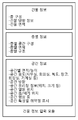
도 3은 본 발명의 다른 실시예에 있어서, 건물 정보에 대한 세부 구성을 나타내는 도면이다.3 is a diagram showing a detailed configuration of building information in another embodiment of the present invention.
정보 입력부가 입력 받는 세부적인 정보 중 건물 및 공간에 대한 세부적인 정보는 다음과 같은 세부 입력 요소로 구성될 수 있다.The detailed information on the building and space among the detailed information on which the information input unit receives the input may be composed of the following detailed input elements.
건물 정보 입력 모듈은는 건물 정보로서 건물에 대한 층 구성 정보, 건물의 방향 및 방위에 대한 정보, 전체 건물에 대한 건물 면적에 대한 정보 등을 입력으로 받아들이고, 층별 정보로서 각 층별 공간에 대한 구성 정보, 층별 면적에 대한 정보 및 층별 구조에 대한 정보 등을 입력으로 받아들일 수 있다.The building information input module receives the building information about the building, the information about the direction and the orientation of the building, and the information about the building area of the entire building as building information. The building information input module receives configuration information, Information on the floor area and information on the floor structure can be inputted.
또한, 공간 정보로서 공간별 면적 및 높이에 대한 정보, 공간의 용도에 대한 정보(예를 들어, 사무실, 회의실, 복도, 창고, 화장실, 기계실 등), 공간의 방향에 대한 정보, 공간에서 유리창에 대한 정보(위치 및 크기 등), 공간의 열원 위치에 대한 정보, 공간 흡/배기 장치 위치에 대한 정보, 공간의 형상에 대한 정보, 공간 특성별 취약점에 대한 정보 등일 건물 정보의 세부적인 정보로 받아들여 센서 배치 자동화 계산을 위한 기본 데이터로 활용한다.In addition, as the spatial information, information on the area and the height of each space, information on the purpose of the space (for example, office, conference room, hall, warehouse, toilet, machine room, etc.), information on the direction of the space, Information about the position of the heat source in the space, information on the position of the space intake / exhaust device, information on the shape of the space, information on the vulnerability according to the spatial characteristics, etc. It is used as basic data for automatic calculation of sensor layout.
본 발명에 따른 센서 자동화 배치 장치는 센서에 대한 자동화 배치 기능을 제공하기 위하여 사용자로부터 도 3과 같은 건물 정보를 입력 받을 수 있다. 한편, 센서 자동화 배치 장치에는 센서 자동화 배치 관리자 기능에 의하여 센서 종류, 센서에 대한 특성, 센서별 배치를 위한 기준(일례로 센서간 거리, 센서 신호 범위 등) 및 센서 배치에 대한 지식이 저장될 수 있다. 이러한 센서의 특성 및 센서 배치에 대한 지식은 필요에 따라서는 언제든지 도구 관리자에 의하여 새로운 내용으로 갱신될 수 있다.The sensor automatic placement apparatus according to the present invention can receive building information as shown in FIG. 3 from a user to provide an automatic placement function for a sensor. On the other hand, the sensor automation arrangement device can store the sensor type, the characteristics of the sensor, the criteria for placement by sensor (for example, the distance between the sensors, the sensor signal range, etc.) have. The nature of these sensors and their knowledge of sensor placement can be updated with new content by the tool manager at any time, as needed.
건물에 대한 정보 입력이 완료되면, 센서 자동화 배치 장치는 사용자에 의해 입력되는 취약 정보 및 특수조건 등을 이용하여 각 센서별로 가장 먼저 취약지구로 고려되어 반드시 센서가 설치되어야 하는 센서 위치를 찾아낼 수 있다. 이러한 취약 포인트는 일 예로, 온도 센서의 경우 창문 근접위치 및 최원거리 위치, 열원 근접 위치 및 열원과의 최원거리 위치, 흡/배기 밸브의 근접위치 등이 될 수 있다. 이렇게 계산된 위치를 바탕으로 센서 자동화 배치 장치는 우선적으로 기준 센서가 되는 센서의 위치를 산정할 수 있다.After inputting the information about the building, the sensor automatic placement device is considered to be the first vulnerable region for each sensor by using vulnerable information inputted by the user and special conditions, have. Such a weak point may be, for example, a window close position and a maximum distance position in a temperature sensor, a heat source close position, a minimum distance position with a heat source, and a close position of an intake / exhaust valve. Based on the calculated position, the sensor automatic positioning device can estimate the position of the sensor serving as the reference sensor first.
도 4는 본 발명의 일실시예에 있어서, 다음 센서의 배치 위치를 결정하는 방향을 설명하기 위한 예시도이다.4 is an exemplary view for explaining a direction for determining the arrangement position of the next sensor in an embodiment of the present invention.
본 발명에 따른 센서 자동화 배치 장치는 기준 센서의 위치가 산정되면 산정된 기준 센서의 위치(410)를 기준으로 센서 배치의 지식을 이용하여 다음 센서의 위치(420)를 계산할 수 있다.The sensor automatic placement apparatus according to the present invention can calculate the
다음 센서의 위치 계산은 일 예로, 2가지 방식에 의하여 계산될 수 있다. 첫 번째 방식은 센서별로 센서 배치 지식 저장 모듈에 저장되어 있는 센서 간의 배치 간격 정보를 기반으로 배치하는 방식이고, 두 번째 방식은 센서의 신호 범위에 영향을 고려하여 다음 센서의 위치를 결정하는 방식이다.The position calculation of the next sensor can be calculated, for example, by two methods. The first method is based on the arrangement interval information between the sensors stored in the sensor arrangement knowledge storage module for each sensor, and the second method is a method of determining the position of the next sensor considering the influence of the signal range of the sensor .
첫 번째 방식으로는 온도 및 습도 센서의 예로 들 수 있다. 이러한 센서들은 센서 배치 지식 저장 모듈에 저장된 센서간 거리를 기준으로 다음 센서의 위치를 계산한다. 두 번째 배치 방식의 센서로 대표적인 것인 재실 센서가 있다. 재실 센서의 경우는 해당 센서에서 감지해 낼 수 있는 범위를 가지고 있는 특성을 갖는다. 따라서, 해당 센서의 특성에 명시된 센서의 범위를 기반으로 하여 다음 센서의 위치를 계산할 수 있다.The first method is an example of a temperature and humidity sensor. These sensors calculate the position of the next sensor based on the distance between the sensors stored in the sensor placement knowledge storage module. There is a redundant sensor, which is representative of the second batch type of sensor. In the case of a room sensor, the sensor has a range that can be detected by the sensor. Therefore, the position of the next sensor can be calculated based on the range of the sensor specified in the characteristic of the sensor.
일반적으로 센서 배치의 기준은 센서의 어느 한 위치가 결정되면 해당 위치에 배치되는 센서를 기준 센서로 하여 평면 형상에서 4방위로 넓혀가는 방식으로 다음 센서의 배치 위치를 결정할 수 있다.In general, when the sensor is positioned at one position, the position of the next sensor can be determined by using a sensor disposed at the position as a reference sensor and widening the sensor in four directions from the plane shape.
이와 같은 방식으로 센서를 자동으로 배치함에 있어서 중요한 요소는 센서 배치 지식 저장 모듈을 구축하는 것이다. 센서 배치 지식 저장 모듈은 건물의 공간 특성에 따른 센서 배치 기준, 건물의 특성(용도, 방위, 열원, 흡/배기 위치, 창문의 위치, 조명 위치 등)에 따른 센서별 취약 포인트에 선정 및 센서 배치 기준 등으로 구성될 수 있다.An important element in automatically deploying sensors in this manner is to build a sensor deployment knowledge storage module. The sensor placement knowledge storage module selects sensors and positions them according to the sensor placement criterion according to the spatial characteristics of the building, the characteristics of the building (use, orientation, heat source, intake / exhaust position, window position, Standards, and so on.
상기와 같은 센서 배치 지식 저장 모듈을 기반으로 센서 자동화 배치 장치는 다음 센서에 대한 위치(420)를 선정하고, 선정된 위치가 배치 공간 내에 존재하는 좌표인지, 이미 배치된 센서와의 중복성은 없는지를 비교하여 요구된 공간의 모든 범위를 포함할 수 있는 센서 위치를 결정하고, 센서 배치가 완료되면 센서의 자동화 배치에 대한 1차 기능을 완료하고 배치된 센서에 대한 가격 정보를 기반으로 전체 건물 에너지 관리를 위한 센서 배치에 대한 예산 정보 및 각 센서의 위치 정보를 계산하고 이를 화면을 통해 사용자에게 제공할 수 있다. 사용자는 센서 배치 위치 보정 모듈을 이용하여 이러한 센서 배치에 대한 결과에 따라 특수 요구조건에 대한 선호도 및 가격 정보를 바탕으로 센서의 재배치 기능을 수행할 수도 있다.Based on the sensor placement knowledge storage module as described above, the sensor automatic placement apparatus selects a
도 5는 본 발명의 일실시예에 있어서, 빌딩 에너지 관리 시스템 환경 구성을 위한 센서 자동화 배치 방법을 나타내는 흐름도이다.Figure 5 is a flow diagram illustrating a method for automated sensor deployment for a building energy management system environment configuration in one embodiment of the present invention.
센서 자동화 배치 장치는 먼저 빌딩 에너지 관리 시스템이 구축될 건물에 대한 정보, 상기 빌딩 에너지 관리 시스템의 구축에 이용되는 센서에 대한 정보 및 상기 빌딩 에너지 관리 시스템의 구축에 투입되는 투입 예산에 대한 정보를 입력 받는다. 이 때, 센서 자동화 배치 장치는 센서 정보 및 건물 정보 등을 기초로 각각의 센서 특성을 고려하여 취약 지점을 선정할 수 있다(S510). 그리고, 입력 받은 건물, 센서 및 투입 예산에 대한 정보 등을 기초로 센서의 배치 위치를 계산한다.The sensor automatic layout apparatus first inputs information on a building to be constructed with a building energy management system, information on a sensor used for building the building energy management system, and input budget to be used for building the building energy management system Receive. At this time, the sensor automatic placement apparatus can select a vulnerable site based on the sensor information and the building information in consideration of the characteristics of each sensor (S510). Then, the placement position of the sensor is calculated on the basis of information on the inputted building, sensor, and input budget.
센서 자동화 배치 장치는 이와 같은 과정을 통해 기준 센서의 위치가 계산되면, 센서 배치 기본 지식을 이용하여 다음 센서를 배치할 위치를 계산한다(S520).When the position of the reference sensor is calculated through the above-described process, the sensor automatic placement apparatus calculates the position to place the next sensor using the basic knowledge of the sensor arrangement (S520).
일 예로, 센서 자동화 배치 장치는 각 센서별 배치 간격 정보 및 각 센서별 신호 범위 중 적어도 하나를 이용하여 각 센서의 배치 위치를 선정할 수 있다.For example, the sensor automatic placement apparatus can select a placement position of each sensor by using at least one of arrangement interval information for each sensor and signal range for each sensor.
이 때, 센서 자동화 배치 장치는 건물에 대한 정보를 기초로 계산된 센서의 배치 위치가 건물 내에 위치하는지 판단하여(S530), 선정된 센서의 배치 위치가 건물 내에 위치하면 상기 센서의 배치 위치가 기 계산된 센서의 배치 위치와 중복되는지 판단하고(S540), 건물 내에 위치하지 않으면 상기 센서의 배치 위치가 건물의 전체 영역을 포함하는지 판단한다(S550).At this time, the sensor automatic placement apparatus determines whether the placement position of the sensor calculated based on the information about the building is located in the building (S530). If the placement position of the selected sensor is located in the building, (S540). If the location of the sensor is not within the building, it is determined whether the location of the sensor includes the entire area of the building (S550).
또한, 선정된 센서의 배치 위치가 기 계산된 센서의 배치 위치와 중복되지 않으면 계속해서 센서를 배치할 위치를 계산하고, 중복되면 상기 센서의 배치 위치가 건물의 전체 영역을 포함하는지 판단함으로써 센서가 모든 공간을 포함하도록 배치한다.If the arrangement position of the selected sensor does not overlap with the arrangement position of the previously calculated sensor, the position where the sensor is to be arranged is calculated, and if it is determined that the arrangement position of the sensor includes the entire area of the building, All spaces are included.
이후, 센서 자동화 배치 장치는 배치된 센서가 모든 건물의 전체 영역을 포함하는 것으로 판단하면(S560), 계산된 센서의 배치 위치를 사용자 인터페이스부를 통해 표시한다.Thereafter, when the sensor automatic placement apparatus determines that the disposed sensor includes the entire area of all the buildings (S560), the calculated sensor placement position is displayed through the user interface unit.
따라서, 본 발명에 따른 빌딩 에너지 관리 시스템 환경 구성을 위한 센서 자동화 배치 장치 및 그 방법은 건물 에너지 관리 시스템 구성을 함에 있어, 센서를 실제 건물에 설치하기에 앞서 프로그램 상에서 자동으로 건물환경에서 센서 위치를 결정해 보고 결정된 센서의 위치를 확인할 수 있으며, 센서 구성을 위해 필요한 예산을 미리 산정해 볼 수 있을 뿐 아니라, 투입된 예산을 바탕으로 센서 배치를 재구성할 수 있다.Accordingly, in the construction of a building energy management system, a sensor automatic placement apparatus and method for configuring a building energy management system environment configuration according to the present invention automatically detects a sensor location in a building environment before a sensor is installed in a real building It is possible to confirm the position of the sensor determined by the determination, to estimate the budget necessary for the sensor configuration in advance, and to reconfigure the sensor arrangement based on the input budget.
본 발명에 따른 센서 자동화 배치 방법은 다양한 컴퓨터 수단을 통하여 수행될 수 있는 프로그램 명령 형태로 구현되어 컴퓨터 판독 가능 매체에 기록될 수 있다. 상기 컴퓨터 판독 가능 매체는 프로그램 명령, 데이터 파일, 데이터 구조 등을 단독으로 또는 조합하여 포함할 수 있다. 상기 매체에 기록되는 프로그램 명령은 본 발명을 위하여 특별히 설계되고 구성된 것들이거나 컴퓨터 소프트웨어 당업자에게 공지되어 사용 가능한 것일 수도 있다. 컴퓨터 판독 가능 기록 매체의 예에는 하드 디스크, 플로피 디스크 및 자기 테이프와 같은 자기 매체(magnetic media), CD-ROM, DVD와 같은 광기록 매체(optical media), 플롭티컬 디스크(floptical disk)와 같은 자기-광 매체(magneto-optical media), 및 롬(ROM), 램(RAM), 플래시 메모리 등과 같은 프로그램 명령을 저장하고 수행하도록 특별히 구성된 하드웨어 장치가 포함된다. 프로그램 명령의 예에는 컴파일러에 의해 만들어지는 것과 같은 기계어 코드뿐만 아니라 인터프리터 등을 사용해서 컴퓨터에 의해서 실행될 수 있는 고급 언어 코드를 포함한다. 상기된 하드웨어 장치는 본 발명의 동작을 수행하기 위해 하나 이상의 소프트웨어 모듈로서 작동하도록 구성될 수 있으며, 그 역도 마찬가지이다.The sensor automation arrangement method according to the present invention may be implemented in the form of a program command that can be executed through various computer means and recorded in a computer readable medium. The computer-readable medium may include program instructions, data files, data structures, and the like, alone or in combination. The program instructions recorded on the medium may be those specially designed and constructed for the present invention or may be available to those skilled in the art of computer software. Examples of computer-readable media include magnetic media such as hard disks, floppy disks and magnetic tape; optical media such as CD-ROMs and DVDs; magnetic media such as floppy disks; Magneto-optical media, and hardware devices specifically configured to store and execute program instructions such as ROM, RAM, flash memory, and the like. Examples of program instructions include machine language code such as those produced by a compiler, as well as high-level language code that can be executed by a computer using an interpreter or the like. The hardware devices described above may be configured to operate as one or more software modules to perform the operations of the present invention, and vice versa.
이상과 같이 본 발명은 비록 한정된 실시예와 도면에 의해 설명되었으나, 본 발명은 상기의 실시예에 한정되는 것은 아니며, 본 발명이 속하는 분야에서 통상의 지식을 가진 자라면 이러한 기재로부터 다양한 수정 및 변형이 가능하다.While the invention has been shown and described with reference to certain preferred embodiments thereof, it will be understood by those of ordinary skill in the art that various changes in form and details may be made therein without departing from the spirit and scope of the invention as defined by the appended claims. This is possible.
그러므로, 본 발명의 범위는 설명된 실시예에 국한되어 정해져서는 아니 되며, 후술하는 특허청구범위뿐 아니라 이 특허청구범위와 균등한 것들에 의해 정해져야 한다.Therefore, the scope of the present invention should not be limited to the described embodiments, but should be determined by the equivalents of the claims, as well as the claims.
100: 센서 자동화 배치 장치
110: 정보 입력부
120: 센서 배치부
122: 전체 영역 센서 배치 위치 계산 모듈
124: 센서 배치 예산 계산 모듈
126: 예산 반영 센서 배치 위치 계산 모듈
130: 사용자 인터페이스부
140: 예산 및 추가 요구조건 입력부100: Sensor automatic placement device
110: Information input unit
120: Sensor arrangement section
122: full area sensor placement position calculation module
124: Sensor placement budget calculation module
126: budgeting sensor placement location calculation module
130:
140: Budget and Additional Requirements Inputs
Claims (14)
상기 입력 받은 건물, 센서 및 투입 예산에 대한 정보를 기초로 상기 건물에서 상기 센서의 배치 위치 및 상기 빌딩 에너지 관리 시스템의 구축에 이용되는 센서에 대한 가격 정보를 기반으로 건물 에너지 관리를 위한 건물의 전체 영역을 포함하는 위치에 센서를 배치하는데 필요로 하는 예산을 계산하는 센서 배치부; 및
상기 계산된 센서의 배치 위치 및 예산을 표시하는 사용자 인터페이스부
를 포함하고,
상기 센서 배치부는,
상기 건물에 대한 정보에 포함된 취약 정보로부터 각 센서별 취약 지구를 확인하고 상기 취약 지구를 보완하기 위해 상기 건물 내 센서가 설치되어야 하는 센서 위치를 계산한 후, 계산된 센서 위치를 바탕으로 상기 센서의 배치 지식에 따른 각 센서별 배치 간격 정보, 각 센서별 신호 범위를 고려하여 건물 내 복수의 센서들 중 센서에 대한 자동화 배치를 위한 기준이 되는 제1 센서의 배치 위치를 결정하고, 결정된 제1 센서의 배치 위치에 기초하여 평면상에서 4방위 방향으로 다음에 위치할 제2 센서의 배치 위치를 결정하고,
상기 제2 센서의 배치 위치는.
상기 계산된 제2 센서의 배치 위치가 건물의 배치 공간 내에 존재하는 좌표인지 또는 건물 내 이미 배치된 센서와의 중복성이 없는지를 고려하여 건물의 배치 공간의 모든 범위를 포함할 수 있도록 결정된 위치이며,
상기 사용자 인터페이스부는,
상기 건물의 환경에서 배치 가능한 센서의 배치 위치 및 센서의 배치 위치에 따른 구성을 위해 필요한 예산에 기초하여 상기 계산된 예산을 통해 상기 센서의 배치 위치를 재구성하는 센서 자동화 배치 장치.An information input unit for receiving information on a building in which the building energy management system is to be installed, information on sensors installed / disposed in the building energy management system, and input budget to be used for building the building energy management system;
Based on the input information of the building, the sensor, and the input budget, based on the arrangement position of the sensor in the building and the price information about the sensor used in building the building energy management system, A sensor arrangement unit for calculating a budget required for disposing the sensor at a position including the area; And
A user interface unit for displaying the calculated position and budget of the sensor,
Lt; / RTI >
The sensor arrangement unit includes:
A vulnerable zone for each sensor is identified from vulnerable information included in the information on the building, a sensor location where a sensor in the building is to be installed is calculated to supplement the vulnerable zone, The arrangement position of the first sensor as a reference for the automatic placement of the sensors among the plurality of sensors in the building is determined in consideration of the arrangement interval information of each sensor according to the arrangement knowledge of the sensors and the signal range of each sensor, Determining an arrangement position of a second sensor to be positioned next in a four-azimuth direction on a plane on the basis of the arrangement position of the sensor,
The arrangement position of the second sensor is.
A position determined so as to include the entire range of the arrangement space of the building in consideration of whether the calculated position of the second sensor is present in the arrangement space of the building or whether there is redundancy with the sensor already disposed in the building,
The user interface unit,
And restructuring the arrangement position of the sensor through the calculated budget based on a budget necessary for a configuration according to a placement position of the sensor and a placement position of the sensor in an environment of the building.
상기 정보 입력부는,
상기 건물의 층별/공간별 구조와 특성에 대한 정보를 입력 받는 건물 정보 입력 모듈;
상기 건물의 취약 정보와 사용자가 요구하는 특수 조건을 입력 받는 취약 정보 및 특수 조건 입력 모듈;
기 설정된 상기 투입 예산에 대한 정보를 입력 받는 예산 정보 입력 모듈;
상기 센서의 특성과 규격에 대한 정보를 입력 받는 센서 특성 정보 입력 모듈; 및
상기 센서의 배치 위치를 선정하기 위한 상기 센서의 배치 지식에 대한 정보를 입력 받는 센서 배치 지식 입력 모듈
을 포함하는 것을 특징으로 하는 센서 자동화 배치 장치.The method according to claim 1,
Wherein the information input unit comprises:
A building information input module for receiving information on structure and characteristics of each building / space of the building;
Vulnerable information and special condition input module receiving vulnerable information of the building and special condition requested by the user;
A budget information input module receiving information on the predetermined input budget;
A sensor characteristic information input module for receiving information on characteristics and specifications of the sensor; And
A sensor placement knowledge input module for receiving information on placement knowledge of the sensor for selecting the placement position of the sensor,
And a sensor for detecting the position of the sensor.
상기 입력 받은 건물, 센서 및 투입 예산에 대한 정보를 저장하는 정보 저장부
를 더 포함하는 것을 특징으로 하는 센서 자동화 배치 장치.The method according to claim 1,
An information storage unit for storing information on the inputted building, sensor, and input budget,
Further comprising a sensor for detecting the position of the sensor.
상기 정보 저장부는,
상기 건물의 층별/공간별 구조와 특성에 대한 정보를 저장하는 건물 정보 저장 모듈;
상기 센서의 특성과 규격에 대한 정보를 저장하는 센서 특성 저장 모듈;
상기 센서의 배치 위치를 선정하기 위한 상기 센서의 배치 지식에 대한 정보를 저장하는 센서 배치 지식 저장 모듈;
상기 투입 예산에 대한 정보를 기초로 센서 배치 결과를 저장하는 예산별 센서 배치 결과 저장 모듈; 및
상기 건물의 전체 영역을 커버하는 센서 배치 위치에 대한 정보를 저장하는 전체 영역 센서 배치 위치 저장 모듈
을 포함하는 것을 특징으로 하는 센서 자동화 배치 장치.The method of claim 3,
The information storage unit stores,
A building information storage module for storing information on structure and characteristics of each building / space;
A sensor characteristic storage module for storing information on characteristics and specifications of the sensor;
A sensor placement knowledge storage module for storing information on placement knowledge of the sensor for selecting a placement position of the sensor;
A budget-based sensor placement result storage module for storing a sensor placement result based on the information on the input budget; And
An overall area sensor placement location storage module < RTI ID = 0.0 >
And a sensor for detecting the position of the sensor.
상기 센서 배치부는,
상기 입력 받은 건물 및 센서에 대한 정보를 기초로 상기 건물의 전체 영역에서 상기 센서의 배치 위치를 계산하는 전체 영역 센서 배치 위치 계산 모듈; 및
상기 입력 받은 건물, 센서 및 투입 예산에 대한 정보를 기초로 상기 건물에서 상기 센서의 배치 위치를 계산하는 예산 반영 센서 배치 위치 계산 모듈
을 포함하는 것을 특징으로 하는 센서 자동화 배치 장치.The method according to claim 1,
The sensor arrangement unit includes:
A total area sensor arrangement position calculation module for calculating an arrangement position of the sensor in the entire area of the building based on the information on the inputted building and sensor; And
A budget reflecting sensor placement position calculating module for calculating a placement position of the sensor in the building based on the information on the input building,
And a sensor for detecting the position of the sensor.
상기 사용자 인터페이스부는,
상기 계산된 센서의 배치 위치를 표시하는 센서 배치 결과 표시 모듈; 및
상기 계산된 센서의 배치 위치를 보정하는 센서 배치 위치 보정 모듈
을 포함하는 것을 특징으로 하는 센서 자동화 배치 장치.The method according to claim 1,
The user interface unit,
A sensor arrangement result display module for displaying the calculated arrangement position of the sensor; And
And a sensor arrangement position correction module
And a sensor for detecting the position of the sensor.
상기 입력 받은 건물, 센서 및 투입 예산에 대한 정보를 기초로 상기 건물에서 상기 센서의 배치 위치 및 상기 빌딩 에너지 관리 시스템의 구축에 이용되는 센서에 대한 가격 정보를 기반으로 건물 에너지 관리를 위한 건물의 전체 영역을 포함하는 위치에 센서를 배치하는데 필요로 하는 예산을 계산하는 단계; 및
상기 계산된 센서의 배치 위치 및 예산을 표시하는 단계
를 포함하고,
상기 계산하는 단계는,
상기 건물에 대한 정보에 포함된 취약 정보로부터 각 센서별 취약 지구를 확인하고 상기 취약 지구를 보완하기 위해 상기 건물 내 센서가 설치되어야 하는 센서 위치를 계산한 후, 계산된 센서 위치를 바탕으로 상기 센서의 배치 지식에 따른 각 센서별 배치 간격 정보, 각 센서별 신호 범위를 고려하여 건물 내 복수의 센서들 중 센서에 대한 자동화 배치를 위한 기준이 되는 제1 센서의 배치 위치를 결정하고, 결정된 제1 센서의 배치 위치에 기초하여 평면상에서 4방위 방향으로 다음에 위치할 제2 센서의 배치 위치를 결정하고,
상기 제2 센서의 배치 위치는.
상기 계산된 제2 센서의 배치 위치가 건물의 배치 공간 내에 존재하는 좌표인지 또는 건물 내 이미 배치된 센서와의 중복성이 없는지를 고려하여 건물의 배치 공간의 모든 범위를 포함할 수 있도록 결정된 위치이며,
상기 표시하는 단계는,
상기 건물의 환경에서 배치 가능한 센서의 배치 위치 및 센서의 배치 위치에 따른 구성을 위해 필요한 예산에 기초하여 상기 계산된 예산을 통해 상기 센서의 배치 위치를 재구성하는 센서 자동화 배치 방법.Receiving information on buildings to be installed in the building energy management system, information on sensors installed / placed in the building energy management system, and information on input budgets to be used for building the building energy management system;
Based on the input information of the building, the sensor, and the input budget, based on the arrangement position of the sensor in the building and the price information about the sensor used in building the building energy management system, Calculating a budget required to place the sensor at a location including the area; And
Displaying the calculated placement and budget of the sensor
Lt; / RTI >
Wherein the calculating step comprises:
A vulnerable zone for each sensor is identified from vulnerable information included in the information on the building, a sensor location where a sensor in the building is to be installed is calculated to supplement the vulnerable zone, The arrangement position of the first sensor as a reference for the automatic placement of the sensors among the plurality of sensors in the building is determined in consideration of the arrangement interval information of each sensor according to the arrangement knowledge of the sensors and the signal range of each sensor, Determining an arrangement position of a second sensor to be positioned next in a four-azimuth direction on a plane on the basis of the arrangement position of the sensor,
The arrangement position of the second sensor is.
A position determined so as to include the entire range of the arrangement space of the building in consideration of whether the calculated position of the second sensor is present in the arrangement space of the building or whether there is redundancy with the sensor already disposed in the building,
Wherein the displaying comprises:
Wherein the placement of the sensors is reconfigured based on a budget necessary for a configuration according to a placement position of the sensors and a placement position of the sensors in the environment of the building.
Priority Applications (2)
| Application Number | Priority Date | Filing Date | Title |
|---|---|---|---|
| KR1020120018478A KR101891624B1 (en) | 2012-02-23 | 2012-02-23 | Apparatus and operation method of automatic sensor configuration to configure the building environment for building energy management system |
| US13/774,131 US9568899B2 (en) | 2012-02-23 | 2013-02-22 | Apparatus and method for automatically configuring sensor to configure building energy management system |
Applications Claiming Priority (1)
| Application Number | Priority Date | Filing Date | Title |
|---|---|---|---|
| KR1020120018478A KR101891624B1 (en) | 2012-02-23 | 2012-02-23 | Apparatus and operation method of automatic sensor configuration to configure the building environment for building energy management system |
Publications (2)
| Publication Number | Publication Date |
|---|---|
| KR20130096907A KR20130096907A (en) | 2013-09-02 |
| KR101891624B1 true KR101891624B1 (en) | 2018-08-27 |
Family
ID=49004150
Family Applications (1)
| Application Number | Title | Priority Date | Filing Date |
|---|---|---|---|
| KR1020120018478A Expired - Fee Related KR101891624B1 (en) | 2012-02-23 | 2012-02-23 | Apparatus and operation method of automatic sensor configuration to configure the building environment for building energy management system |
Country Status (2)
| Country | Link |
|---|---|
| US (1) | US9568899B2 (en) |
| KR (1) | KR101891624B1 (en) |
Families Citing this family (25)
| Publication number | Priority date | Publication date | Assignee | Title |
|---|---|---|---|---|
| US11732527B2 (en) | 2009-12-22 | 2023-08-22 | View, Inc. | Wirelessly powered and powering electrochromic windows |
| US20130271813A1 (en) | 2012-04-17 | 2013-10-17 | View, Inc. | Controller for optically-switchable windows |
| US10303035B2 (en) | 2009-12-22 | 2019-05-28 | View, Inc. | Self-contained EC IGU |
| US11592723B2 (en) | 2009-12-22 | 2023-02-28 | View, Inc. | Automated commissioning of controllers in a window network |
| US11630366B2 (en) | 2009-12-22 | 2023-04-18 | View, Inc. | Window antennas for emitting radio frequency signals |
| US11054792B2 (en) | 2012-04-13 | 2021-07-06 | View, Inc. | Monitoring sites containing switchable optical devices and controllers |
| US12400651B2 (en) | 2012-04-13 | 2025-08-26 | View Operating Corporation | Controlling optically-switchable devices |
| US11300848B2 (en) | 2015-10-06 | 2022-04-12 | View, Inc. | Controllers for optically-switchable devices |
| US10964320B2 (en) | 2012-04-13 | 2021-03-30 | View, Inc. | Controlling optically-switchable devices |
| KR102336168B1 (en) | 2014-03-05 | 2021-12-07 | 뷰, 인크. | Monitoring sites containing switchable optical devices and controllers |
| US11743071B2 (en) | 2018-05-02 | 2023-08-29 | View, Inc. | Sensing and communications unit for optically switchable window systems |
| US12235560B2 (en) | 2014-11-25 | 2025-02-25 | View, Inc. | Faster switching electrochromic devices |
| US11114742B2 (en) | 2014-11-25 | 2021-09-07 | View, Inc. | Window antennas |
| US10673121B2 (en) | 2014-11-25 | 2020-06-02 | View, Inc. | Window antennas |
| KR102436536B1 (en) * | 2016-02-11 | 2022-08-26 | 삼성전자주식회사 | Electronic apparatus and sensor arrangement method thereof |
| KR102071266B1 (en) | 2016-06-21 | 2020-01-30 | 한국전자통신연구원 | Device and method for scent emission by multiple sensors |
| US10667346B2 (en) | 2016-10-03 | 2020-05-26 | Signify Holding B.V. | Lighting control configuration |
| CA3062815A1 (en) | 2017-04-26 | 2018-11-01 | View, Inc. | Tintable window system computing platform |
| US20220004175A1 (en) * | 2018-10-25 | 2022-01-06 | Siemens Aktiengesellschaft | Apparatus and Method for Computer-Implemented Determination of Sensor Positions in a Simulated Process of an Automation System |
| JP7169898B2 (en) * | 2019-02-15 | 2022-11-11 | 株式会社日立製作所 | Manufacturing monitoring support device, manufacturing monitoring support method, and manufacturing monitoring support program |
| JP7644501B2 (en) | 2019-05-09 | 2025-03-12 | ビュー オペレーティング コーポレーション | Antenna systems for controlled coverage within buildings |
| US11631493B2 (en) | 2020-05-27 | 2023-04-18 | View Operating Corporation | Systems and methods for managing building wellness |
| CA3142270A1 (en) | 2019-05-31 | 2020-12-03 | View, Inc. | Building antenna |
| TW202206925A (en) | 2020-03-26 | 2022-02-16 | 美商視野公司 | Access and messaging in a multi client network |
| US20240192649A1 (en) * | 2021-04-07 | 2024-06-13 | View, Inc. | Control system of a facility |
Citations (1)
| Publication number | Priority date | Publication date | Assignee | Title |
|---|---|---|---|---|
| JP2000187680A (en) * | 1998-12-22 | 2000-07-04 | Oki Business Co Ltd | Print circuit board design system and its method using the same |
Family Cites Families (9)
| Publication number | Priority date | Publication date | Assignee | Title |
|---|---|---|---|---|
| US6941193B2 (en) * | 2003-02-12 | 2005-09-06 | Awi Licensing Company | Sensor system for measuring and monitoring indoor air quality |
| KR100964449B1 (en) | 2007-12-18 | 2010-06-16 | 엘에스전선 주식회사 | Building Energy Management System and Its Control Method |
| US20110057929A1 (en) * | 2008-03-03 | 2011-03-10 | Honeywell International Inc | Model driven 3d geometric modeling system |
| KR101079816B1 (en) * | 2008-12-22 | 2011-11-03 | 한국전자통신연구원 | Sensor network modeling system |
| KR101222131B1 (en) * | 2009-10-08 | 2013-01-15 | 한국전자통신연구원 | Determination method of relay node's location for wireless sensor network and system thereof |
| KR20110066527A (en) | 2009-12-11 | 2011-06-17 | 한국전자통신연구원 | Sensor network emulation device |
| US8265870B1 (en) * | 2010-01-20 | 2012-09-11 | Sandia Corporation | Real-time method for establishing a detection map for a network of sensors |
| KR20110110919A (en) | 2010-04-02 | 2011-10-10 | 인천대학교 산학협력단 | Geographic information system-based sensor initial placement method, optimal sensor placement method and device using the same, and recording medium recording program for implementing the same |
| US8843238B2 (en) * | 2011-09-30 | 2014-09-23 | Johnson Controls Technology Company | Systems and methods for controlling energy use in a building management system using energy budgets |
-
2012
- 2012-02-23 KR KR1020120018478A patent/KR101891624B1/en not_active Expired - Fee Related
-
2013
- 2013-02-22 US US13/774,131 patent/US9568899B2/en not_active Expired - Fee Related
Patent Citations (1)
| Publication number | Priority date | Publication date | Assignee | Title |
|---|---|---|---|---|
| JP2000187680A (en) * | 1998-12-22 | 2000-07-04 | Oki Business Co Ltd | Print circuit board design system and its method using the same |
Also Published As
| Publication number | Publication date |
|---|---|
| US20130226353A1 (en) | 2013-08-29 |
| US9568899B2 (en) | 2017-02-14 |
| KR20130096907A (en) | 2013-09-02 |
Similar Documents
| Publication | Publication Date | Title |
|---|---|---|
| KR101891624B1 (en) | Apparatus and operation method of automatic sensor configuration to configure the building environment for building energy management system | |
| US11356519B2 (en) | Floor-plan based learning and registration of distributed devices | |
| US20250231454A1 (en) | Automated commissioning of controllers in a window network | |
| US20230393443A1 (en) | Virtually viewing devices in a facility | |
| EP3275204B1 (en) | System and method for capturing and analyzing multidimensional building information | |
| TWI776719B (en) | Automated commissioning of controllers in a window network | |
| EP3274974B1 (en) | Floor plan based planning of building systems | |
| CN107660290B (en) | Integrated system for sale, installation and maintenance of building systems | |
| US10928785B2 (en) | Floor plan coverage based auto pairing and parameter setting | |
| CN107660300B (en) | System and method for providing a graphical user interface indicating intruder threat levels for a building | |
| EP3079110A1 (en) | System and method for energy harvesting system planning and performance | |
| WO2022098630A1 (en) | Virtually viewing devices in a facility | |
| US20180102858A1 (en) | System and method for determining rf sensor performance relative to a floor plan | |
| US20250298929A1 (en) | Discretisation of building models to enable the spatial positioning of technical components | |
| KR102437121B1 (en) | System for providing underground information to support underground exploration sites based on integrated underground space map | |
| US20250068787A1 (en) | System, method and computer program product for construction | |
| US20250053696A1 (en) | Building management design system using space modeling | |
| US20240354458A1 (en) | System, method and computer program product for structural floor construction using optimized design | |
| KR20090022247A (en) | Methods and systems for automatically defining sensor networks | |
| KR102084968B1 (en) | Apparatus and method for determining position of device providing mobile communication service | |
| WO2025050028A9 (en) | Automated determination of clearance requirements in construction of a building | |
| JP4152849B2 (en) | Building plan tolerance search system and method | |
| CN115964770A (en) | System and method for guiding installation of intrusion sensor |
Legal Events
| Date | Code | Title | Description |
|---|---|---|---|
| PA0109 | Patent application |
St.27 status event code: A-0-1-A10-A12-nap-PA0109 |
|
| PG1501 | Laying open of application |
St.27 status event code: A-1-1-Q10-Q12-nap-PG1501 |
|
| PN2301 | Change of applicant |
St.27 status event code: A-3-3-R10-R13-asn-PN2301 St.27 status event code: A-3-3-R10-R11-asn-PN2301 |
|
| A201 | Request for examination | ||
| PA0201 | Request for examination |
St.27 status event code: A-1-2-D10-D11-exm-PA0201 |
|
| D13-X000 | Search requested |
St.27 status event code: A-1-2-D10-D13-srh-X000 |
|
| D14-X000 | Search report completed |
St.27 status event code: A-1-2-D10-D14-srh-X000 |
|
| E902 | Notification of reason for refusal | ||
| PE0902 | Notice of grounds for rejection |
St.27 status event code: A-1-2-D10-D21-exm-PE0902 |
|
| E13-X000 | Pre-grant limitation requested |
St.27 status event code: A-2-3-E10-E13-lim-X000 |
|
| P11-X000 | Amendment of application requested |
St.27 status event code: A-2-2-P10-P11-nap-X000 |
|
| P13-X000 | Application amended |
St.27 status event code: A-2-2-P10-P13-nap-X000 |
|
| E701 | Decision to grant or registration of patent right | ||
| PE0701 | Decision of registration |
St.27 status event code: A-1-2-D10-D22-exm-PE0701 |
|
| GRNT | Written decision to grant | ||
| PR0701 | Registration of establishment |
St.27 status event code: A-2-4-F10-F11-exm-PR0701 |
|
| PR1002 | Payment of registration fee |
St.27 status event code: A-2-2-U10-U11-oth-PR1002 Fee payment year number: 1 |
|
| PG1601 | Publication of registration |
St.27 status event code: A-4-4-Q10-Q13-nap-PG1601 |
|
| PC1903 | Unpaid annual fee |
St.27 status event code: A-4-4-U10-U13-oth-PC1903 Not in force date: 20210821 Payment event data comment text: Termination Category : DEFAULT_OF_REGISTRATION_FEE |
|
| PC1903 | Unpaid annual fee |
St.27 status event code: N-4-6-H10-H13-oth-PC1903 Ip right cessation event data comment text: Termination Category : DEFAULT_OF_REGISTRATION_FEE Not in force date: 20210821 |