JP7619480B2 - Engagement device - Google Patents
Engagement device Download PDFInfo
- Publication number
- JP7619480B2 JP7619480B2 JP2023562380A JP2023562380A JP7619480B2 JP 7619480 B2 JP7619480 B2 JP 7619480B2 JP 2023562380 A JP2023562380 A JP 2023562380A JP 2023562380 A JP2023562380 A JP 2023562380A JP 7619480 B2 JP7619480 B2 JP 7619480B2
- Authority
- JP
- Japan
- Prior art keywords
- engagement element
- rotating member
- friction engagement
- axial direction
- axial
- Prior art date
- Legal status (The legal status is an assumption and is not a legal conclusion. Google has not performed a legal analysis and makes no representation as to the accuracy of the status listed.)
- Active
Links
- 230000007246 mechanism Effects 0.000 claims description 399
- 230000033001 locomotion Effects 0.000 claims description 84
- 230000005540 biological transmission Effects 0.000 claims description 38
- 230000004044 response Effects 0.000 claims description 6
- 230000002093 peripheral effect Effects 0.000 description 51
- 239000003638 chemical reducing agent Substances 0.000 description 20
- 238000010586 diagram Methods 0.000 description 13
- 230000009467 reduction Effects 0.000 description 12
- 230000008859 change Effects 0.000 description 6
- 230000009471 action Effects 0.000 description 3
- 239000003990 capacitor Substances 0.000 description 2
- 238000002485 combustion reaction Methods 0.000 description 2
- 230000008878 coupling Effects 0.000 description 2
- 238000010168 coupling process Methods 0.000 description 2
- 238000005859 coupling reaction Methods 0.000 description 2
- 238000005096 rolling process Methods 0.000 description 2
- 230000009194 climbing Effects 0.000 description 1
- 238000005516 engineering process Methods 0.000 description 1
- 230000004048 modification Effects 0.000 description 1
- 238000012986 modification Methods 0.000 description 1
Images


Classifications
-
- F—MECHANICAL ENGINEERING; LIGHTING; HEATING; WEAPONS; BLASTING
- F16—ENGINEERING ELEMENTS AND UNITS; GENERAL MEASURES FOR PRODUCING AND MAINTAINING EFFECTIVE FUNCTIONING OF MACHINES OR INSTALLATIONS; THERMAL INSULATION IN GENERAL
- F16D—COUPLINGS FOR TRANSMITTING ROTATION; CLUTCHES; BRAKES
- F16D13/00—Friction clutches
- F16D13/22—Friction clutches with axially-movable clutching members
- F16D13/38—Friction clutches with axially-movable clutching members with flat clutching surfaces, e.g. discs
- F16D13/52—Clutches with multiple lamellae ; Clutches in which three or more axially moveable members are fixed alternately to the shafts to be coupled and are pressed from one side towards an axially-located member
-
- B—PERFORMING OPERATIONS; TRANSPORTING
- B60—VEHICLES IN GENERAL
- B60T—VEHICLE BRAKE CONTROL SYSTEMS OR PARTS THEREOF; BRAKE CONTROL SYSTEMS OR PARTS THEREOF, IN GENERAL; ARRANGEMENT OF BRAKING ELEMENTS ON VEHICLES IN GENERAL; PORTABLE DEVICES FOR PREVENTING UNWANTED MOVEMENT OF VEHICLES; VEHICLE MODIFICATIONS TO FACILITATE COOLING OF BRAKES
- B60T1/00—Arrangements of braking elements, i.e. of those parts where braking effect occurs specially for vehicles
- B60T1/02—Arrangements of braking elements, i.e. of those parts where braking effect occurs specially for vehicles acting by retarding wheels
- B60T1/06—Arrangements of braking elements, i.e. of those parts where braking effect occurs specially for vehicles acting by retarding wheels acting otherwise than on tread, e.g. employing rim, drum, disc, or transmission or on double wheels
- B60T1/062—Arrangements of braking elements, i.e. of those parts where braking effect occurs specially for vehicles acting by retarding wheels acting otherwise than on tread, e.g. employing rim, drum, disc, or transmission or on double wheels acting on transmission parts
-
- F—MECHANICAL ENGINEERING; LIGHTING; HEATING; WEAPONS; BLASTING
- F16—ENGINEERING ELEMENTS AND UNITS; GENERAL MEASURES FOR PRODUCING AND MAINTAINING EFFECTIVE FUNCTIONING OF MACHINES OR INSTALLATIONS; THERMAL INSULATION IN GENERAL
- F16D—COUPLINGS FOR TRANSMITTING ROTATION; CLUTCHES; BRAKES
- F16D28/00—Electrically-actuated clutches
-
- F—MECHANICAL ENGINEERING; LIGHTING; HEATING; WEAPONS; BLASTING
- F16—ENGINEERING ELEMENTS AND UNITS; GENERAL MEASURES FOR PRODUCING AND MAINTAINING EFFECTIVE FUNCTIONING OF MACHINES OR INSTALLATIONS; THERMAL INSULATION IN GENERAL
- F16D—COUPLINGS FOR TRANSMITTING ROTATION; CLUTCHES; BRAKES
- F16D55/00—Brakes with substantially-radial braking surfaces pressed together in axial direction, e.g. disc brakes
- F16D55/24—Brakes with substantially-radial braking surfaces pressed together in axial direction, e.g. disc brakes with a plurality of axially-movable discs, lamellae, or pads, pressed from one side towards an axially-located member
- F16D55/26—Brakes with substantially-radial braking surfaces pressed together in axial direction, e.g. disc brakes with a plurality of axially-movable discs, lamellae, or pads, pressed from one side towards an axially-located member without self-tightening action
- F16D55/36—Brakes with a plurality of rotating discs all lying side by side
-
- F—MECHANICAL ENGINEERING; LIGHTING; HEATING; WEAPONS; BLASTING
- F16—ENGINEERING ELEMENTS AND UNITS; GENERAL MEASURES FOR PRODUCING AND MAINTAINING EFFECTIVE FUNCTIONING OF MACHINES OR INSTALLATIONS; THERMAL INSULATION IN GENERAL
- F16D—COUPLINGS FOR TRANSMITTING ROTATION; CLUTCHES; BRAKES
- F16D65/00—Parts or details
- F16D65/14—Actuating mechanisms for brakes; Means for initiating operation at a predetermined position
- F16D65/16—Actuating mechanisms for brakes; Means for initiating operation at a predetermined position arranged in or on the brake
- F16D65/18—Actuating mechanisms for brakes; Means for initiating operation at a predetermined position arranged in or on the brake adapted for drawing members together, e.g. for disc brakes
-
- F—MECHANICAL ENGINEERING; LIGHTING; HEATING; WEAPONS; BLASTING
- F16—ENGINEERING ELEMENTS AND UNITS; GENERAL MEASURES FOR PRODUCING AND MAINTAINING EFFECTIVE FUNCTIONING OF MACHINES OR INSTALLATIONS; THERMAL INSULATION IN GENERAL
- F16D—COUPLINGS FOR TRANSMITTING ROTATION; CLUTCHES; BRAKES
- F16D67/00—Combinations of couplings and brakes; Combinations of clutches and brakes
- F16D67/02—Clutch-brake combinations
-
- F—MECHANICAL ENGINEERING; LIGHTING; HEATING; WEAPONS; BLASTING
- F16—ENGINEERING ELEMENTS AND UNITS; GENERAL MEASURES FOR PRODUCING AND MAINTAINING EFFECTIVE FUNCTIONING OF MACHINES OR INSTALLATIONS; THERMAL INSULATION IN GENERAL
- F16D—COUPLINGS FOR TRANSMITTING ROTATION; CLUTCHES; BRAKES
- F16D21/00—Systems comprising a plurality of actuated clutches
- F16D21/02—Systems comprising a plurality of actuated clutches for interconnecting three or more shafts or other transmission members in different ways
- F16D21/06—Systems comprising a plurality of actuated clutches for interconnecting three or more shafts or other transmission members in different ways at least two driving shafts or two driven shafts being concentric
- F16D2021/0676—Mechanically actuated multiple lamellae clutches
-
- F—MECHANICAL ENGINEERING; LIGHTING; HEATING; WEAPONS; BLASTING
- F16—ENGINEERING ELEMENTS AND UNITS; GENERAL MEASURES FOR PRODUCING AND MAINTAINING EFFECTIVE FUNCTIONING OF MACHINES OR INSTALLATIONS; THERMAL INSULATION IN GENERAL
- F16D—COUPLINGS FOR TRANSMITTING ROTATION; CLUTCHES; BRAKES
- F16D2121/00—Type of actuator operation force
- F16D2121/18—Electric or magnetic
- F16D2121/24—Electric or magnetic using motors
-
- F—MECHANICAL ENGINEERING; LIGHTING; HEATING; WEAPONS; BLASTING
- F16—ENGINEERING ELEMENTS AND UNITS; GENERAL MEASURES FOR PRODUCING AND MAINTAINING EFFECTIVE FUNCTIONING OF MACHINES OR INSTALLATIONS; THERMAL INSULATION IN GENERAL
- F16D—COUPLINGS FOR TRANSMITTING ROTATION; CLUTCHES; BRAKES
- F16D2125/00—Components of actuators
- F16D2125/18—Mechanical mechanisms
- F16D2125/20—Mechanical mechanisms converting rotation to linear movement or vice versa
- F16D2125/34—Mechanical mechanisms converting rotation to linear movement or vice versa acting in the direction of the axis of rotation
- F16D2125/36—Helical cams, Ball-rotating ramps
- F16D2125/38—Helical cams, Ball-rotating ramps with plural cam or ball-ramp mechanisms arranged concentrically with the brake rotor axis
-
- F—MECHANICAL ENGINEERING; LIGHTING; HEATING; WEAPONS; BLASTING
- F16—ENGINEERING ELEMENTS AND UNITS; GENERAL MEASURES FOR PRODUCING AND MAINTAINING EFFECTIVE FUNCTIONING OF MACHINES OR INSTALLATIONS; THERMAL INSULATION IN GENERAL
- F16D—COUPLINGS FOR TRANSMITTING ROTATION; CLUTCHES; BRAKES
- F16D2125/00—Components of actuators
- F16D2125/18—Mechanical mechanisms
- F16D2125/20—Mechanical mechanisms converting rotation to linear movement or vice versa
- F16D2125/34—Mechanical mechanisms converting rotation to linear movement or vice versa acting in the direction of the axis of rotation
- F16D2125/40—Screw-and-nut
-
- F—MECHANICAL ENGINEERING; LIGHTING; HEATING; WEAPONS; BLASTING
- F16—ENGINEERING ELEMENTS AND UNITS; GENERAL MEASURES FOR PRODUCING AND MAINTAINING EFFECTIVE FUNCTIONING OF MACHINES OR INSTALLATIONS; THERMAL INSULATION IN GENERAL
- F16D—COUPLINGS FOR TRANSMITTING ROTATION; CLUTCHES; BRAKES
- F16D2125/00—Components of actuators
- F16D2125/18—Mechanical mechanisms
- F16D2125/44—Mechanical mechanisms transmitting rotation
- F16D2125/46—Rotating members in mutual engagement
- F16D2125/48—Rotating members in mutual engagement with parallel stationary axes, e.g. spur gears
Landscapes
- Engineering & Computer Science (AREA)
- General Engineering & Computer Science (AREA)
- Mechanical Engineering (AREA)
- Transportation (AREA)
- Physics & Mathematics (AREA)
- Electromagnetism (AREA)
- Mechanical Operated Clutches (AREA)
- Braking Arrangements (AREA)
Description
本発明は、クラッチ機構及びブレーキ機構を備えた係合装置に関する。 The present invention relates to an engagement device equipped with a clutch mechanism and a brake mechanism.
このような係合装置の一例が、下記の特許文献1に開示されている。以下、背景技術の説明では、特許文献1における符号を括弧内に引用する。An example of such an engagement device is disclosed in the following
特許文献1に開示された係合装置(3)は、第1回転部材(33)と第2回転部材(34)とを選択的に係合するクラッチ機構(31)と、第1回転部材(33)を非回転部材(35)に対して選択的に係合するブレーキ機構(32)と、を備えている。The engagement device (3) disclosed in
クラッチ機構(31)は、第1回転部材(33)と一体的に回転するように連結された第1摩擦係合要素(31b)と、第2回転部材(34)と一体的に回転するように連結された第2摩擦係合要素(31a)と、を備えている。ブレーキ機構(32)は、第1回転部材(33)と一体的に回転するように連結された第3摩擦係合要素(32a)と、非回転部材(35)に固定された第4摩擦係合要素(32b)と、を備えている。The clutch mechanism (31) includes a first frictional engagement element (31b) connected to rotate integrally with the first rotating member (33) and a second frictional engagement element (31a) connected to rotate integrally with the second rotating member (34). The brake mechanism (32) includes a third frictional engagement element (32a) connected to rotate integrally with the first rotating member (33) and a fourth frictional engagement element (32b) fixed to a non-rotating member (35).
特許文献1に開示された係合装置(3)は、クラッチ機構(31)の第1摩擦係合要素(31b)及び第2摩擦係合要素(31a)を軸方向(特許文献1の図2における左右方向)に押圧する第1押圧機構(72)と、ブレーキ機構(32)の第3摩擦係合要素(32a)及び第4摩擦係合要素(32b)を軸方向に押圧する第2押圧機構(77)と、を備えている。The engagement device (3) disclosed in
クラッチ機構(31)とブレーキ機構(32)とは、径方向(特許文献1の図2における上下方向)に並んで配置されている。また、第1押圧機構(72)は、クラッチ機構(31)に対して軸方向の一方側(特許文献1の図2における右側)に配置されている。そして、第2押圧機構(77)は、ブレーキ機構(32)に対して軸方向の他方側(特許文献1の図2における右側)に配置されている。このような構成は、係合装置(3)の大型化を招いていた。The clutch mechanism (31) and the brake mechanism (32) are arranged side by side in the radial direction (the up-down direction in FIG. 2 of Patent Document 1). The first pressing mechanism (72) is arranged on one axial side (the right side in FIG. 2 of Patent Document 1) of the clutch mechanism (31). The second pressing mechanism (77) is arranged on the other axial side (the right side in FIG. 2 of Patent Document 1) of the brake mechanism (32). This configuration leads to an increase in size of the engagement device (3).
そこで、クラッチ機構及びブレーキ機構を備えた構成において、小型化を図ることができる係合装置の実現が望まれる。 Therefore, it is desirable to realize an engagement device that can be made smaller in size in a configuration that includes a clutch mechanism and a brake mechanism.
上記に鑑みた、係合装置の特徴構成は、
第1回転部材と第2回転部材とを選択的に係合するクラッチ機構と、
前記第1回転部材及び前記第2回転部材のいずれか一方である対象回転部材と非回転部材とを選択的に係合するブレーキ機構と、を備えた係合装置であって、
前記クラッチ機構及び前記ブレーキ機構の係合の状態を変化させる押圧機構を備え、
前記第1回転部材の回転軸心に沿う方向を軸方向とし、前記軸方向の一方側を軸方向第1側とし、前記軸方向の他方側を軸方向第2側として、
前記クラッチ機構は、前記第1回転部材と一体的に回転するように連結された第1摩擦係合要素と、前記第2回転部材と一体的に回転するように連結された第2摩擦係合要素と、を備え、
前記第1摩擦係合要素及び前記第2摩擦係合要素は、互いに前記軸方向に対向するように配置され、前記軸方向に押し付けられることで互いに摩擦係合し、
前記ブレーキ機構は、前記対象回転部材と一体的に回転するように連結された第3摩擦係合要素と、前記非回転部材に固定された第4摩擦係合要素と、を備え、
前記第3摩擦係合要素及び前記第4摩擦係合要素は、前記第1摩擦係合要素及び前記第2摩擦係合要素に対して前記軸方向第2側に離間した位置で、互いに前記軸方向に対向するように配置され、前記軸方向に押し付けられることで互いに摩擦係合し、
前記押圧機構は、前記第1摩擦係合要素及び前記第2摩擦係合要素と、前記第3摩擦係合要素及び前記第4摩擦係合要素と、の前記軸方向の間に配置された押圧部と、前記押圧部と連動するように連結された被駆動部と、前記被駆動部を前記軸方向に移動させる直動機構と、を備え、
前記第1回転部材、前記第2回転部材、前記第1摩擦係合要素、前記第2摩擦係合要素、前記第3摩擦係合要素、及び前記第4摩擦係合要素が、同軸上に配置され、
前記直動機構によって前記被駆動部が前記軸方向第1側に移動するか前記軸方向第2側に移動するに応じて、前記クラッチ機構と前記ブレーキ機構とが選択的に係合される点にある。
In view of the above, the characteristic configuration of the engagement device is as follows:
a clutch mechanism for selectively engaging the first rotating member and the second rotating member;
a brake mechanism that selectively engages a target rotating member, which is one of the first rotating member and the second rotating member, with a non-rotating member,
a pressing mechanism for changing an engagement state of the clutch mechanism and the brake mechanism,
A direction along the rotation axis of the first rotating member is defined as an axial direction, one side in the axial direction is defined as an axial first side, and the other side in the axial direction is defined as an axial second side,
the clutch mechanism includes a first friction engagement element connected to the first rotating member so as to rotate integrally with the first rotating member, and a second friction engagement element connected to the second rotating member so as to rotate integrally with the second rotating member,
the first friction engagement element and the second friction engagement element are disposed to face each other in the axial direction and are frictionally engaged with each other by being pressed against each other in the axial direction;
the brake mechanism includes a third friction engagement element connected to the target rotating member so as to rotate integrally with the target rotating member, and a fourth friction engagement element fixed to the non-rotating member,
the third friction engagement element and the fourth friction engagement element are disposed to face each other in the axial direction at a position spaced apart from the first friction engagement element and the second friction engagement element on the second axial side, and are pressed against each other in the axial direction to frictionally engage with each other,
the pressing mechanism includes a pressing portion disposed between the first friction engagement element and the second friction engagement element and the third friction engagement element and the fourth friction engagement element in the axial direction, a driven portion connected to be interlocked with the pressing portion, and a linear motion mechanism that moves the driven portion in the axial direction,
the first rotating member, the second rotating member, the first frictional engagement element, the second frictional engagement element, the third frictional engagement element, and the fourth frictional engagement element are coaxially arranged,
The clutch mechanism and the brake mechanism are selectively engaged in response to the driven part being moved axially toward the first side or the second side by the linear motion mechanism.
この特徴構成によれば、直動機構により被駆動部を介して軸方向に移動する押圧部が、第1摩擦係合要素及び第2摩擦係合要素と、それらに対して軸方向第2側に配置された第3摩擦係合要素及び第4摩擦係合要素との軸方向の間に配置されている。そして、直動機構により被駆動部が軸方向第1側に移動することで、第1摩擦係合要素及び第2摩擦係合要素が押圧部により押圧されてクラッチ機構が係合状態となると共に、押圧部による第3摩擦係合要素及び第4摩擦係合要素の押圧が解除されてブレーキ機構が解放状態となる。一方、直動機構により被駆動部が軸方向第2側に移動することで、第3摩擦係合要素及び第4摩擦係合要素が押圧部により押圧されてブレーキ機構が係合状態となると共に、押圧部による第1摩擦係合要素及び第2摩擦係合要素の押圧が解除されてクラッチ機構が解放状態となる。これにより、クラッチ機構とブレーキ機構との係合の状態を、共通の押圧機構により変化させることができる。したがって、クラッチ機構及びブレーキ機構を備えた構成において、係合装置の小型化を図ることができる。According to this characteristic configuration, the pressing portion, which moves in the axial direction via the driven portion by the linear motion mechanism, is disposed between the first and second frictional engagement elements and the third and fourth frictional engagement elements disposed on the second axial side relative to them. Then, when the driven portion moves to the first axial side by the linear motion mechanism, the first and second frictional engagement elements are pressed by the pressing portion, and the clutch mechanism is in an engaged state, and the pressing of the third and fourth frictional engagement elements by the pressing portion is released, and the brake mechanism is in a released state. On the other hand, when the driven portion moves to the second axial side by the linear motion mechanism, the third and fourth frictional engagement elements are pressed by the pressing portion, and the brake mechanism is in an engaged state, and the pressing of the first and second frictional engagement elements by the pressing portion is released, and the clutch mechanism is in a released state. This allows the engagement state of the clutch mechanism and the brake mechanism to be changed by a common pressing mechanism. Therefore, in a configuration equipped with a clutch mechanism and a brake mechanism, it is possible to reduce the size of the engagement device.
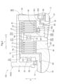
1.第1の実施形態に係る係合装置
以下では、第1の実施形態に係る係合装置100について、図面を参照して説明する。図1に示すように、係合装置100は、第1回転部材81と第2回転部材82とを選択的に係合するクラッチ機構1と、第1回転部材81及び第2回転部材82のいずれか一方である対象回転部材8Tと非回転部材NRとを選択的に係合するブレーキ機構2と、クラッチ機構1及びブレーキ機構2の係合の状態を変化させる押圧機構3と、を備えている。
1. Engagement Device According to First Embodiment An
第1回転部材81と第2回転部材82とは、互いに相対回転自在に支持されている。以下の説明では、第1回転部材81の回転軸心に沿う方向を「軸方向L」とする。そして、軸方向Lの一方側を「軸方向第1側L1」とし、他方側を「軸方向第2側L2」とする。また、第1回転部材81等の回転部材の回転軸心に直交する方向を、各回転軸心を基準とした「径方向R」とする。なお、どの回転軸心を基準とするかを区別する必要がない場合やどの回転軸心を基準とするかが明らかである場合には、単に「径方向R」と記す場合がある。The first rotating
本実施形態では、非回転部材NRは、係合装置100を収容するケース9である。本実施形態では、ケース9は、第1周壁部91と、第1側壁部92と、支持壁部93と、カバー部94と、を備えている。In this embodiment, the non-rotating member NR is a
第1周壁部91は、第1回転部材81及び第2回転部材82の径方向Rの外側を覆うように形成されている。第1側壁部92は、第1回転部材81及び第2回転部材82の軸方向第1側L1を覆うように形成されている。支持壁部93は、第1回転部材81及び第2回転部材82の軸方向第2側L2を覆うように形成されている。カバー部94は、支持壁部93の軸方向第2側L2を覆うように形成されている。The first
本実施形態では、第1周壁部91は、軸方向Lに沿う軸心を有する筒状に形成されている。そして、第1周壁部91の軸方向第1側L1の開口が、第1側壁部92によって塞がれている。また、第1周壁部91の軸方向第2側L2の開口が、支持壁部93によって塞がれている。本例では、第1周壁部91と第1側壁部92とが一体的に形成され、第1ケース部9Aを構成している。そして、第1周壁部91に対して径方向Rの内側に支持壁部93が位置するように、当該支持壁部93を備えた第2ケース部9Bが、軸方向第1側L1から第1ケース部9Aに嵌め込まれている。また、カバー部94を備えた第3ケース部9Cが、第2ケース部9Bに対して軸方向第1側L1から接合されている。In this embodiment, the first
クラッチ機構1は、第1回転部材81と一体的に回転するように連結された第1摩擦係合要素11と、第2回転部材82と一体的に回転するように連結された第2摩擦係合要素12と、を備えている。The
第1摩擦係合要素11と第2摩擦係合要素12とは、互いに軸方向Lに対向するように配置されている。そして、第1摩擦係合要素11と第2摩擦係合要素12とは、軸方向Lに押し付けられることで互いに摩擦係合する。本実施形態では、第1摩擦係合要素11及び第2摩擦係合要素12は、複数枚ずつ設けられており、これらが軸方向Lに沿って交互に配置されている。第1摩擦係合要素11及び第2摩擦係合要素12は、いずれか一方をフリクションプレートとし、他方をセパレートプレートとすることができる。The first
ブレーキ機構2は、対象回転部材8Tと一体的に回転するように連結された第3摩擦係合要素21と、非回転部材NRに固定された第4摩擦係合要素22と、を備えている。なお、本実施形態では、第1回転部材81が対象回転部材8Tである。The
第3摩擦係合要素21と第4摩擦係合要素22とは、互いに軸方向Lに対向するように配置されている。そして、第3摩擦係合要素21と第4摩擦係合要素22とは、軸方向Lに押し付けられることで互いに摩擦係合する。また、第3摩擦係合要素21と第4摩擦係合要素22とは、第1摩擦係合要素11及び第2摩擦係合要素12に対して軸方向第2側L2に離間して配置されている。本実施形態では、第3摩擦係合要素21及び第4摩擦係合要素22は、複数枚ずつ設けられており、これらが軸方向Lに沿って交互に配置されている。第3摩擦係合要素21及び第4摩擦係合要素22は、いずれか一方をフリクションプレートとし、他方をセパレートプレートとすることができる。The third
第1回転部材81、第2回転部材82、第1摩擦係合要素11、第2摩擦係合要素12、第3摩擦係合要素21、及び第4摩擦係合要素22は、第1軸X1上に配置されている。つまり、第1回転部材81、第2回転部材82、第1摩擦係合要素11、第2摩擦係合要素12、第3摩擦係合要素21、及び第4摩擦係合要素22は、同軸上に配置されている。The first rotating
図2に示すように、本実施形態では、第1回転部材81は、第1摩擦係合要素11が連結された第1連結部8aを備えている。そして、第2回転部材82は、第2摩擦係合要素12が連結された第2連結部8bを備えている。また、対象回転部材8Tは、第3摩擦係合要素21が連結された第3連結部8cを備えている。つまり、本実施形態では、第1回転部材81が第3連結部8cを備えている。また、非回転部材NRは、第4摩擦係合要素22が連結された第4連結部8dを備えている。
As shown in FIG. 2, in this embodiment, the first rotating
第1連結部8aは、第1摩擦係合要素11に対して径方向Rの外側であって、径方向Rに沿う径方向視で第1摩擦係合要素11と重複する位置に配置されている。つまり、第1摩擦係合要素11は、第1連結部8aによって径方向Rの外側から支持されている。そして、第1摩擦係合要素11は、第1連結部8aに対して相対回転が規制された状態で、軸方向Lに摺動可能に支持されている。本例では、第1摩擦係合要素11の外周部には、軸方向Lに延在する複数のスプライン溝が周方向に分散して形成されている。一方、第1連結部8aの内周部にも、同様のスプライン溝が周方向に分散して形成されている。そして、それらのスプライン溝同士が係合されている。ここで、2つの要素の配置に関して、「特定方向視で重複する」とは、その視線方向に平行な仮想直線を当該仮想直線と直交する各方向に移動させた場合に、当該仮想直線が2つの要素の双方に交わる領域が少なくとも一部に存在することを指す。The first connecting
第2連結部8bは、第2摩擦係合要素12に対して径方向Rの内側であって、径方向Rに沿う径方向視で第2摩擦係合要素12及び第1連結部8aと重複する位置に配置されている。つまり、第2摩擦係合要素12は、第2連結部8bによって径方向Rの内側から支持されている。そして、第2摩擦係合要素12は、第2連結部8bに対して相対回転が規制された状態で、軸方向Lに摺動可能に支持されている。本例では、第2摩擦係合要素12の内周部には、軸方向Lに延在する複数のスプライン溝が周方向に分散して形成されている。一方、第2連結部8bの外周部にも、同様のスプライン溝が周方向に分散して形成されている。そして、それらのスプライン溝同士が係合されている。The second connecting
第3連結部8cは、第3摩擦係合要素21に対して径方向Rの外側であって、径方向Rに沿う径方向視で第3摩擦係合要素21と重複する位置に配置されている。つまり、第3摩擦係合要素21は、第3連結部8cによって径方向Rの外側から支持されている。そして、第3摩擦係合要素21は、第3連結部8cに対して相対回転が規制された状態で、軸方向Lに摺動可能に支持されている。本例では、第3摩擦係合要素21の外周部には、軸方向Lに延在する複数のスプライン溝が周方向に分散して形成されている。一方、第3連結部8cの内周部にも、同様のスプライン溝が周方向に分散して形成されている。そして、それらのスプライン溝同士が係合されている。The third connecting
第4連結部8dは、第4摩擦係合要素22に対して径方向Rの内側であって、径方向Rに沿う径方向視で第4摩擦係合要素22及び第3連結部8cと重複する位置に配置されている。つまり、第4摩擦係合要素22は、第4連結部8dによって径方向Rの内側から支持されている。そして、第4摩擦係合要素22は、第4連結部8dに対して相対回転が規制された状態で、軸方向Lに摺動可能に支持されている。本例では、第4摩擦係合要素22の内周部には、軸方向Lに延在する複数のスプライン溝が周方向に分散して形成されている。一方、第4連結部8dの外周部にも、同様のスプライン溝が周方向に分散して形成されている。そして、それらのスプライン溝同士が係合されている。The fourth connecting
図2に示すように、本実施形態では、第1回転部材81は、第1外側支持部811と、第1径方向延在部812と、を備えている。As shown in FIG. 2, in this embodiment, the first rotating
第1外側支持部811は、第1軸X1を軸心とする筒状に形成されている。本実施形態では、第1外側支持部811に、第1連結部8a及び第3連結部8cが配置されている。The first
第1径方向延在部812は、第1軸X1を基準とする径方向Rに沿って延在するように形成されている。本実施形態では、第1径方向延在部812は、第1外側支持部811における軸方向第1側L1の端部から径方向Rの内側に延在するように形成されている。また、本実施形態では、第1径方向延在部812は、第1軸受B1を介して、ケース9の第1側壁部92に対して回転自在に支持されている。本例では、第1軸受B1は、第1径方向延在部812と第1側壁部92との軸方向Lの間に配置されたスラスト軸受である。The first
本実施形態では、第2回転部材82は、第1内側支持部821を備えている。第1内側支持部821は、第1外側支持部811に対して径方向Rの内側に配置されている。本実施形態では、第1内側支持部821に、第2連結部8bが配置されている。In this embodiment, the second rotating
本実施形態では、ケース9の支持壁部93は、第2内側支持部931を備えている。第2内側支持部931は、第1外側支持部811に対して径方向Rの内側に配置されている。本実施形態では、第2内側支持部931は、第1軸X1を軸心とする筒状に形成されている。本実施形態では、第2内側支持部931に、第4連結部8dが配置されている。In this embodiment, the
押圧機構3は、第1摩擦係合要素11及び第2摩擦係合要素12と、第3摩擦係合要素21及び第4摩擦係合要素22と、の軸方向Lの間に配置された押圧部31と、押圧部31と連動するように連結された被駆動部32と、被駆動部32を軸方向Lに移動させる直動機構33と、を備えている。The
直動機構33により被駆動部32が軸方向第1側L1に移動することで、第1摩擦係合要素11及び第2摩擦係合要素12が押圧部31により押圧されてクラッチ機構1が係合状態となると共に、押圧部31による第3摩擦係合要素21及び第4摩擦係合要素22の押圧が解除されてブレーキ機構2が解放状態となる。一方、直動機構33により被駆動部32が軸方向第2側L2に移動することで、第3摩擦係合要素21及び第4摩擦係合要素22が押圧部31により押圧されてブレーキ機構2が係合状態となると共に、押圧部31による第1摩擦係合要素11及び第2摩擦係合要素12の押圧が解除されてクラッチ機構1が解放状態となる。このように、直動機構33によって被駆動部32が軸方向第1側L1に移動するか軸方向第2側L2に移動するに応じて、クラッチ機構1とブレーキ機構2とが選択的に係合される。
When the driven
以上のように、係合装置100は、
第1回転部材81と第2回転部材82とを選択的に係合するクラッチ機構1と、
第1回転部材81及び第2回転部材82のいずれか一方である対象回転部材8Tと非回転部材NRとを選択的に係合するブレーキ機構2と、を備えた係合装置100であって、
クラッチ機構1及びブレーキ機構2の係合の状態を変化させる押圧機構3を備え、
クラッチ機構1は、第1回転部材81と一体的に回転するように連結された第1摩擦係合要素11と、第2回転部材82と一体的に回転するように連結された第2摩擦係合要素12と、を備え、
第1摩擦係合要素11及び第2摩擦係合要素12は、互いに軸方向Lに対向するように配置され、軸方向Lに押し付けられることで互いに摩擦係合し、
ブレーキ機構2は、対象回転部材8Tと一体的に回転するように連結された第3摩擦係合要素21と、非回転部材NRに固定された第4摩擦係合要素22と、を備え、
第3摩擦係合要素21及び第4摩擦係合要素22は、第1摩擦係合要素11及び第2摩擦係合要素12に対して軸方向第2側L2に離間した位置で、互いに軸方向Lに対向するように配置され、軸方向Lに押し付けられることで互いに摩擦係合し、
押圧機構3は、第1摩擦係合要素11及び第2摩擦係合要素12と、第3摩擦係合要素21及び第4摩擦係合要素22と、の軸方向Lの間に配置された押圧部31と、当該押圧部31と連動するように連結された被駆動部32と、当該被駆動部32を軸方向Lに移動させる直動機構33と、を備え、
第1回転部材81、第2回転部材82、第1摩擦係合要素11、第2摩擦係合要素12、第3摩擦係合要素21、及び第4摩擦係合要素22が、同軸上に配置され、
直動機構33によって被駆動部32が軸方向第1側L1に移動するか軸方向第2側L2に移動するに応じて、クラッチ機構1とブレーキ機構2とが選択的に係合される。
As described above, the
a
An
A
The
The first
The
The third
The
a first rotating
The
この構成によれば、直動機構33により被駆動部32を介して軸方向Lに移動する押圧部31が、第1摩擦係合要素11及び第2摩擦係合要素12と、それらに対して軸方向第2側L2に配置された第3摩擦係合要素21及び第4摩擦係合要素22との軸方向Lの間に配置されている。そして、直動機構33により被駆動部32が軸方向第1側L1に移動することで、第1摩擦係合要素11及び第2摩擦係合要素12が押圧部31により押圧されてクラッチ機構1が係合状態となると共に、押圧部31による第3摩擦係合要素21及び第4摩擦係合要素22の押圧が解除されてブレーキ機構2が解放状態となる。一方、直動機構33により被駆動部32が軸方向第2側L2に移動することで、第3摩擦係合要素21及び第4摩擦係合要素22が押圧部31により押圧されてブレーキ機構2が係合状態となると共に、押圧部31による第1摩擦係合要素11及び第2摩擦係合要素12の押圧が解除されてクラッチ機構1が解放状態となる。これにより、クラッチ機構1とブレーキ機構2との係合の状態を、共通の押圧機構3により変化させることができる。したがって、クラッチ機構1及びブレーキ機構2を備えた構成において、係合装置100の小型化を図ることができる。According to this configuration, the
本実施形態では、直動機構33は、非回転部材NRに対して回転自在に支持されたねじ軸331と、当該ねじ軸331に螺合するナット部材332と、を備えている。In this embodiment, the
ねじ軸331の外周部には、ねじ山が形成されている。ねじ軸331は、軸方向Lに沿って延在するように形成されている。本実施形態では、ねじ軸331は、第1軸X1上に配置されている。A screw thread is formed on the outer periphery of the
ナット部材332の内周部には、ねじ軸331のねじ山に係合する溝が形成されている。ナット部材332は、ねじ軸331が回転することにより、当該回転方向とねじ軸331のねじ山の向きとに応じて軸方向Lに沿う直線運動を行う。本実施形態では、ナット部材332は、被駆動部32と一体的に軸方向Lに移動するように連結されている。そのため、本実施形態では、ねじ軸331の回転に伴い、ナット部材332及び被駆動部32を介して、押圧部31が軸方向Lに移動する。A groove that engages with the threads of the
また、本実施形態では、ナット部材332は、非回転部材NRに対して、軸方向Lに相対移動可能であると共に相対回転が規制された状態で支持されている。本例では、ナット部材332は、ケース9における支持壁部93の第2内側支持部931に対して径方向Rの内側に配置されている。そして、ナット部材332は、当該ナット部材332の外周部と第2内側支持部931の内周部との径方向Rの間に配置された連結部材33aにより、ケース9に対して軸方向Lに相対移動可能であると共に相対回転が規制された状態で、第2内側支持部931に連結されている。In this embodiment, the
本実施形態では、直動機構33は、第2連結部8bに対して軸方向第2側L2に配置されている。更に、直動機構33は、第4連結部8dに対して径方向Rの内側であって、径方向Rに沿う径方向視で第4連結部8dと重複する位置に配置されている。本例では、直動機構33のねじ軸331及びナット部材332は、第2回転部材82の第1内側支持部821よりも軸方向第2側L2に配置されている。更に、ねじ軸331及びナット部材332は、ケース9における支持壁部93の第2内側支持部931よりも径方向Rの内側に配置されている。In this embodiment, the
このように、本実施形態では、第1回転部材81は、第1摩擦係合要素11が連結された第1連結部8aを備え、
第2回転部材82は、第2摩擦係合要素12が連結された第2連結部8bを備え、
対象回転部材8Tは、第3摩擦係合要素21が連結された第3連結部8cを備え、
非回転部材NRは、第4摩擦係合要素22が連結された第4連結部8dを備え、
第1連結部8aは、第1摩擦係合要素11に対して径方向Rの外側であって、径方向Rに沿う径方向視で第1摩擦係合要素11と重複する位置に配置され、
第3連結部8cは、第3摩擦係合要素21に対して径方向Rの外側であって、径方向Rに沿う径方向視で第3摩擦係合要素21と重複する位置に配置され、
第2連結部8bは、第2摩擦係合要素12に対して径方向Rの内側であって、径方向Rに沿う径方向視で第2摩擦係合要素12及び第1連結部8aと重複する位置に配置され、
第4連結部8dは、第4摩擦係合要素22に対して径方向Rの内側であって、径方向Rに沿う径方向視で第4摩擦係合要素22及び第3連結部8cと重複する位置に配置され、
直動機構33は、第2連結部8bに対して軸方向第2側L2に配置されていると共に、第4連結部8dに対して径方向Rの内側であって径方向Rに沿う径方向視で第4連結部8dと重複する位置に配置されている。
In this manner, in the present embodiment, the first rotating
The second rotating
The
The non-rotating member NR includes a fourth connecting
The first connecting
The third connecting
The second connecting
The fourth connecting
The
この構成によれば、直動機構33が、第2回転部材82の第2連結部8bに対して軸方向第2側L2に配置されている。これにより、直動機構33が第2連結部8bと径方向視で重複するように配置された構成と比べて、係合装置100の径方向Rの寸法を小さく抑えることができる。
また、本構成によれば、直動機構33が、非回転部材NRの第4連結部8dに対して径方向Rの内側であって径方向Rに沿う径方向視で第4連結部8dと重複する位置に配置されている。これにより、直動機構33が第4連結部8dよりも軸方向Lにずれて配置された構成と比べて、係合装置100の軸方向Lの寸法を小さく抑えることができる。また、非回転部材NRの第4連結部8dに対して径方向Rの内側に配置された直動機構33を、非回転部材NRによって支持することが容易であるため、直動機構33の支持構造を簡素化し易い。
According to this configuration, the
Moreover, according to this configuration, the
本実施形態では、押圧部31は、第1押圧部分311と、第2押圧部分312と、を備えている。In this embodiment, the
第1押圧部分311は、第1摩擦係合要素11及び第2摩擦係合要素12を軸方向Lに押圧するように構成されている。第2押圧部分312は、第3摩擦係合要素21及び第4摩擦係合要素22を軸方向Lに押圧するように構成されている。本実施形態では、第1押圧部分311と第2押圧部分312とは、軸方向Lに対向するように配置された別部材により構成されている。そして、第1押圧部分311と第2押圧部分312とは、第4軸受B4を介して、互いに相対回転自在に支持されている。そのため、本実施形態では、第1押圧部分311と第2押圧部分312とは、相対回転可能な状態で、軸方向Lに連動するように構成されている。なお、本例では、第4軸受B4は、第1押圧部分311と第2押圧部分312との軸方向Lの間に配置されたスラスト軸受である。The first
第1押圧部分311は、第1回転部材81又は第2回転部材82に対して、軸方向Lに相対移動可能であると共に一体的に回転する状態で支持されている。本実施形態では、第1押圧部分311は、第1回転部材81の第1外側支持部811に対して、軸方向Lに相対移動可能であると共に一体的に回転する状態で支持されている。本例では、第1押圧部分311の径方向Rの外側の端部が、第1連結部8aに連結されている。The first
第2押圧部分312は、非回転部材NRに対して、軸方向Lに相対移動可能であると共に相対回転が規制された状態で支持されている。本実施形態では、第2押圧部分312は、被駆動部32と一体的に軸方向Lに移動するように連結されている。本例では、第2押圧部分312から径方向Rの内側に延在するように、被駆動部32が形成されている。また、上述したように、本実施形態では、ナット部材332が、非回転部材NRに対して軸方向Lに相対移動可能であると共に相対回転が規制された状態で支持されている。そのため、本実施形態では、第2押圧部分312は、被駆動部32及びナット部材332を介して、非回転部材NRに対して軸方向Lに相対移動可能であると共に相対回転が規制された状態で支持されている。The second
このように、本実施形態では、押圧部31は、第1摩擦係合要素11及び第2摩擦係合要素12を軸方向Lに押圧する第1押圧部分311と、第3摩擦係合要素21及び第4摩擦係合要素22を軸方向Lに押圧する第2押圧部分312と、を備え、
第1押圧部分311は、第1回転部材81又は第2回転部材82に対して、軸方向Lに相対移動可能であると共に一体的に回転する状態で支持され、
第2押圧部分312は、非回転部材NRに対して、軸方向Lに相対移動可能であると共に相対回転が規制された状態で支持され、
第1押圧部分311と第2押圧部分312とは、相対回転可能な状態で、軸方向Lに連動するように構成され、
被駆動部32は、第2押圧部分312と一体的に軸方向Lに移動するように連結されている。
As described above, in the present embodiment, the
The first
The second
The first
The driven
この構成によれば、直動機構33により軸方向Lに移動する被駆動部32が、非回転部材NRに対して相対回転が規制された状態で支持された第2押圧部分312と一体的に軸方向Lに移動するように連結されている。これにより、被駆動部32が第1回転部材81又は第2回転部材82に対して一体的に回転する状態で支持された第1押圧部分311と一体的に軸方向Lに移動するように連結された構成と比べて、押圧機構3の簡素化を図り易い。According to this configuration, the driven
上述したように、本実施形態では、ねじ軸331は、第1軸X1上に配置されている。つまり、本実施形態では、ねじ軸331は、第1摩擦係合要素11、第2摩擦係合要素12、第3摩擦係合要素21、及び第4摩擦係合要素22と同軸上に配置されている。また、本実施形態では、ねじ軸331は、第1摩擦係合要素11、第2摩擦係合要素12、第3摩擦係合要素21、及び第4摩擦係合要素22に対して、径方向Rの内側に配置されている。As described above, in this embodiment, the
このように、本実施形態では、直動機構33は、非回転部材NRに対して回転自在に支持されたねじ軸331と、当該ねじ軸331に螺合するナット部材332と、を備え、
ナット部材332は、被駆動部32と一体的に軸方向Lに移動するように連結され、
ねじ軸331は、第1摩擦係合要素11、第2摩擦係合要素12、第3摩擦係合要素21、及び第4摩擦係合要素22に対して、同軸上であって径方向Rの内側に配置されている。
As described above, in the present embodiment, the
The
The
この構成によれば、第1摩擦係合要素11、第2摩擦係合要素12、第3摩擦係合要素21、及び第4摩擦係合要素22に対して径方向Rの内側に、ナット部材332を軸方向Lに移動させるためのねじ軸331が配置されている。これにより、ねじ軸331を回転駆動させるための駆動力を、それらの摩擦係合要素11,12,21,22に対して軸方向Lの外側からねじ軸331に伝達し易い。したがって、第1摩擦係合要素11及び第2摩擦係合要素12と第3摩擦係合要素21及び第4摩擦係合要素22との軸方向Lの間に配置された押圧部31を、ナット部材332及び被駆動部32を介して軸方向Lに移動可能な構造を実現することが容易となっている。
また、本構成によれば、直動機構33のねじ軸331を、第1摩擦係合要素11、第2摩擦係合要素12、第3摩擦係合要素21、及び第4摩擦係合要素22の少なくとも一部と径方向Rに沿う径方向視で重複するように配置し易い。これにより、直動機構33の配置による、係合装置100の軸方向Lへの大型化を抑制することができる。
According to this configuration, the threaded
Moreover, according to this configuration, it is easy to arrange the
図1に示すように、本実施形態では、係合装置100は、ねじ軸331を回転駆動するための駆動源4と、当該駆動源4とねじ軸331との間の動力伝達を行う伝達機構5と、を更に備えている。As shown in FIG. 1, in this embodiment, the
本実施形態では、駆動源4は、第1軸X1とは異なる第2軸X2上に配置されている。つまり、本実施形態では、駆動源4は、ねじ軸331とは別軸上に配置されている。そして、駆動源4の軸方向Lにおける配置領域が、第1回転部材81の軸方向Lにおける配置領域と重なっている。また、本実施形態では、伝達機構5は、直動機構33に対して軸方向第2側L2に配置されている。In this embodiment, the driving
図2に示すように、本実施形態では、第1回転部材81は、第1軸部材10と一体的に回転するように連結されている。第1軸部材10は、第1回転部材81から軸方向第1側L1に延在するように配置されている。本実施形態では、第1軸部材10は、第1軸X1を軸心とする筒状に形成されている。そして、第1軸部材10は、第1回転部材81の第1外側支持部811における径方向Rの内側の端部から軸方向第1側L1に延在するように形成されている。本例では、第1軸部材10は、第1回転部材81と一体的に形成されている。また、本実施形態では、第1軸部材10は、ケース9の第1側壁部92を軸方向Lに貫通するように配置されている。そして、第1軸部材10は、第2軸受B2を介して、第1側壁部92に対して回転自在に支持されている。本例では、第2軸受B2は、第1軸部材10と第1側壁部92との径方向Rの間に配置されたラジアル軸受である。As shown in FIG. 2, in this embodiment, the first rotating
本実施形態では、第2回転部材82は、第2軸部材20と一体的に回転するように連結されている。第2軸部材20は、第2回転部材82から軸方向第1側L1に延在するように配置されている。本実施形態では、第2軸部材20は、第2回転部材82の第1内側支持部821から軸方向第1側L1に延在するように形成されている。そして、第2軸部材20は、第1軸X1上に配置されている。本例では、第2軸部材20は、第2回転部材82と一体的に形成されている。また、本実施形態では、第2軸部材20は、第1軸部材10の径方向Rの内側を通るように配置されている。そして、第2軸部材20は、第3軸受B3を介して、第1軸部材10に対して相対回転自在に支持されている。本例では、第3軸受B3は、第1軸部材10と第2軸部材20との径方向Rの間に配置されたラジアル軸受である。In this embodiment, the second rotating
なお、係合装置100は、例えば、内燃機関等の駆動力源の駆動力を車輪に伝達する車両用駆動装置に設けられる。この場合、第1軸部材10及び第2軸部材20の一方は、内燃機関等の駆動力源に駆動連結される。そして、第1軸部材10及び第2軸部材20の他方は、車輪に駆動連結される。The
このように、本実施形態では、ねじ軸331を回転駆動するための駆動源4と、当該駆動源4とねじ軸331との間の動力伝達を行う伝達機構5と、を更に備え、
駆動源4は、ねじ軸とは別軸上に配置され、
駆動源4の軸方向Lにおける配置領域が、第1回転部材81の軸方向Lにおける配置領域と重なっており、
伝達機構5は、直動機構33に対して軸方向第2側L2に配置され、
第1回転部材81から軸方向第1側L1に延在するように配置された第1軸部材10が、第1回転部材81と一体的に回転するように連結され、
第2回転部材82から軸方向第1側L1に延在するように配置された第2軸部材20が、第2回転部材82と一体的に回転するように連結されている。
Thus, in this embodiment, the driving
The
an arrangement area of the driving
The
A
The
この構成によれば、駆動源4が第1回転部材81に対して同軸上であって軸方向Lにずれた位置に配置された構成と比べて、係合装置100の軸方向Lの寸法を小さく抑えることができる。
With this configuration, the axial dimension L of the
図1に示すように、本実施形態では、伝達機構5は、第1ギヤ51と、第2ギヤ52と、第3ギヤ53と、第4ギヤ54と、連結体55と、を備えている。As shown in FIG. 1, in this embodiment, the
第1ギヤ51は、駆動源4の出力軸と一体的に回転するように連結されている。本実施形態では、第1ギヤ51は、第2軸X2上に配置されている。そして、第1ギヤ51は、駆動源4に対して軸方向第2側L2に配置されている。The
第2ギヤ52は、第1ギヤ51に噛み合っている。本実施形態では、第2ギヤ52は、第1ギヤ51よりも大径に形成されている。第3ギヤ53は、第2ギヤ52と一体的に回転するように連結されている。本実施形態では、第3ギヤ53は、第2ギヤ52よりも小径に形成されている。また、第3ギヤ53は、第2ギヤ52に対して軸方向第1側L1に配置されている。本実施形態では、第2ギヤ52及び第3ギヤ53は、第1軸X1及び第2軸X2とは異なる第3軸X3上に配置されている。また、本実施形態では、第2ギヤ52及び第3ギヤ53は、第1軸体56により非回転部材NRに対して回転自在に支持されている。第1軸体56は、軸方向Lに沿って延在するように形成されている。本実施形態では、第1軸体56の軸方向第1側L1の端部が、支持壁部93に対して回転自在に支持されている。そして、第1軸体56の軸方向第2側L2の端部が、カバー部94に対して回転自在に支持されている。
The
第4ギヤ54は、第3ギヤ53に噛み合っている。本実施形態では、第4ギヤ54は、第3ギヤ53よりも大径に形成されている。本実施形態では、第4ギヤ54は、第1軸X1上に配置されている。また、本実施形態では、第4ギヤ54は、第2軸体57により非回転部材NRに対して回転自在に支持されている。第2軸体57は、軸方向Lに沿って延在するように形成されている。本実施形態では、第2軸体57の軸方向第2側L2の端部が、カバー部94に対して回転自在に支持されている。一方、第2軸体57の軸方向第1側L1の端部は、連結体55と一体的に回転するように連結されている。
The
本実施形態では、第2ギヤ52の歯数は、第1ギヤ51の歯数よりも多い。そして、第4ギヤ54の歯数は、第2ギヤ52と一体的に回転する第3ギヤ53の歯数よりも多い。そのため、本実施形態では、駆動源4から第1ギヤ51に伝達された回転は、第1ギヤ51と第2ギヤ52との間で減速されて、第3ギヤ53に伝達される。そして、第3ギヤ53の回転は、第3ギヤ53と第4ギヤ54との間で減速されて、連結体55に伝達される。In this embodiment, the number of teeth of the
連結体55は、第4ギヤ54とねじ軸331とが一体的に回転するように、それらを連結する。本実施形態では、連結体55は、軸方向第2側L2が開口する筒状に形成されている。そして、連結体55に対して径方向Rの内側に第2軸体57が配置された状態で、連結体55と第2軸体57とが一体的に回転するように連結されている。また、本実施形態では、連結体55から軸方向第1側L1にねじ軸331が延在するように配置された状態で、連結体55とねじ軸331とが一体的に回転するように連結されている。本実施形態では、連結体55、第2軸体57、及びねじ軸331は、支持壁部93を軸方向Lに貫通するように配置されている。The connecting
図2に示すように、本実施形態では、連結体55は、筒状に形成された、支持壁部93の第2内側支持部931に対して径方向Rの内側に配置されている。本実施形態では、連結体55には、当該連結体55から径方向Rの外側に突出するように形成された被支持部551が設けられている。そして、第2内側支持部931には、当該第2内側支持部931から径方向Rの内側に突出し、被支持部551に対して軸方向第1側L1から対向するように形成された軸受支持部932が設けられている。被支持部551は、第5軸受B5を介して、軸受支持部932に対して回転自在に支持されている。これにより、連結体55は、非回転部材NRに対して軸方向第1側L1に相対移動することが規制された状態で、非回転部材NRに対して回転自在に支持されている。なお、本例では、第5軸受B5は、被支持部551と軸受支持部932との軸方向Lの間に配置されたスラスト軸受である。2, in this embodiment, the connecting
また、本実施形態では、環状の蓋部933が、被支持部551に対して軸方向第2側L2から対向するように、支持壁部93に固定されている。被支持部551は、第6軸受B6を介して、蓋部933に対して回転自在に支持されている。これにより、連結体55は、非回転部材NRに対して軸方向第2側L2に相対移動することが規制された状態で、非回転部材NRに対して回転自在に支持されている。なお、本例では、第6軸受B6は、被支持部551と蓋部933との軸方向Lの間に配置されたスラスト軸受である。In this embodiment, the
本実施形態では、押圧部31による第1摩擦係合要素11及び第2摩擦係合要素12に対する押圧力と、押圧部31による第3摩擦係合要素21及び第4摩擦係合要素22に対する押圧力とを検出する圧力センサ(図示を省略)が設けられている。この圧力センサは、例えば、被支持部551と軸受支持部932との軸方向Lの間、又は、被支持部551と蓋部933との軸方向Lの間に配置される。これにより、被駆動部32、ナット部材332、ねじ軸331を介して連結体55に伝達される、第1摩擦係合要素11、第2摩擦係合要素12、第3摩擦係合要素21、及び第4摩擦係合要素22から押圧部31が受ける力を、圧力センサにより測定することができる。そして、この測定した力に基づいて、押圧部31による第1摩擦係合要素11及び第2摩擦係合要素12に対する押圧力と、押圧部31による第3摩擦係合要素21及び第4摩擦係合要素22に対する押圧力とを算出することができる。In this embodiment, a pressure sensor (not shown) is provided to detect the pressing force of the
2.第2の実施形態に係る係合装置
以下では、第2の実施形態に係る係合装置100について、図3及び図4を参照して説明する。本実施形態では、第2回転部材82が対象回転部材8Tである点で、上記第1の実施形態とは異なっている。以下では、上記第1の実施形態との相違点を中心として説明する。なお、特に説明しない点については、上記第1の実施形態と同様とする。
2. Engagement Device According to a Second Embodiment An
図3及び図4に示すように、本実施形態では、第2回転部材82が対象回転部材8Tである。そのため、本実施形態では、第2回転部材82が、第3摩擦係合要素21が連結された第3連結部8cを備えている。3 and 4, in this embodiment, the second rotating
図4に示すように、本実施形態では、第2回転部材82は、第1内側支持部821に加えて、第2外側支持部822と、第2径方向延在部823と、を更に備えている。As shown in FIG. 4, in this embodiment, the second rotating
第2外側支持部822は、第1軸X1を軸心とする筒状に形成されている。本実施形態では、第2外側支持部822に、第3連結部8cが配置されている。一方、本実施形態では、第1回転部材81の第1外側支持部811には、第3連結部8cが配置されておらず、第1連結部8aが配置されている。本実施形態における第1外側支持部811の軸方向Lの寸法は、上記第1の実施形態における第1外側支持部811の軸方向Lの寸法よりも小さい。そして、第1外側支持部811は、第2外側支持部822に対して軸方向第1側L1に配置されている。The second
第2径方向延在部823は、第1軸X1を基準とする径方向Rに沿って延在するように形成されている。本実施形態では、第2径方向延在部823は、第2外側支持部822における軸方向第1側L1の端部から径方向Rの内側に延在するように形成されている。そして、第2径方向延在部823は、第1内側支持部821に対して、軸方向Lに相対移動可能であると共に一体的に回転する状態で支持されている。本例では、第2径方向延在部823の径方向Rの内側の端部が、第2連結部8bに連結されている。また、本実施形態では、第2径方向延在部823は、第1押圧部分311と一体的に回転するように連結されている。本例では、第2径方向延在部823は、第1押圧部分311と一体的に形成されている。The second
3.第1の実施形態に係る車両用駆動装置
以下では、上記第1の実施形態に係る係合装置100を備えた、第1の実施形態に係る車両用駆動装置1000について、図5から図9を参照して説明する。図5及び図6に示すように、車両用駆動装置1000は、ステータST及びロータRTを備えた回転電機MGと、ロータRTと一体的に回転する入力軸ISと、車輪W(図6参照)に駆動連結される出力ギヤOGと、当該出力ギヤOGに連動して回転するように連結された駆動ギヤDGと、遊星歯車機構PL及び上記の係合装置100を備えた変速機TMと、を備えている。本実施形態では、車両用駆動装置1000は、それぞれが互いに異なる車輪Wと一体的に回転する一対の出力部材OMと、出力ギヤOGの回転を一対の出力部材OMに分配する差動歯車機構DFと、を更に備えている。
3. Vehicle drive device according to the first embodiment Hereinafter, a
駆動ギヤDG、遊星歯車機構PL、及び係合装置100は、ロータRTの回転軸心である第1軸X1上に配置されている。つまり、ロータRTと遊星歯車機構PLと係合装置100と駆動ギヤDGとが、同軸上に配置されている。本実施形態では、出力ギヤOG、一対の出力部材OM、及び差動歯車機構DFは、第1軸X1とは異なる第4軸X4上に配置されている。本例では、第1軸X1と第4軸X4とは、互いに平行に配置されている。The drive gear DG, planetary gear mechanism PL, and
本実施形態では、軸方向Lにおいて、入力軸ISに対して回転電機MGが配置される側を軸方向第1側L1とし、その反対側を軸方向第2側L2としている。In this embodiment, in the axial direction L, the side on which the rotating electric machine MG is arranged relative to the input shaft IS is referred to as the axial first side L1, and the opposite side is referred to as the axial second side L2.
回転電機MGは、車輪W(図6参照)の駆動力源として機能する。回転電機MGは、電力の供給を受けて動力を発生するモータ(電動機)としての機能と、動力の供給を受けて電力を発生するジェネレータ(発電機)としての機能とを有している。具体的には、回転電機MGは、バッテリやキャパシタ等の蓄電装置(図示を省略)と電気的に接続されている。そして、回転電機MGは、蓄電装置に蓄えられた電力により力行して駆動力を発生する。また、回転電機MGは、車輪Wの側から伝達される駆動力により発電を行って蓄電装置を充電する。The rotating electric machine MG functions as a driving force source for the wheels W (see FIG. 6). The rotating electric machine MG has a function as a motor (electric motor) that receives a supply of electric power to generate power, and a function as a generator (electric power generator) that receives a supply of power to generate electric power. Specifically, the rotating electric machine MG is electrically connected to an electric storage device (not shown) such as a battery or a capacitor. The rotating electric machine MG generates driving force by running using the electric power stored in the electric storage device. The rotating electric machine MG also generates power using the driving force transmitted from the wheels W to charge the electric storage device.
回転電機MGのステータSTは、非回転部材NRに固定されている。回転電機MGのロータRTは、ステータSTに対して回転可能に支持されている。The stator ST of the rotating electric machine MG is fixed to the non-rotating member NR. The rotor RT of the rotating electric machine MG is supported rotatably relative to the stator ST.
図5に示すように、本実施形態では、非回転部材NRは、ケース9である。ケース9は、回転電機MG、入力軸IS、出力ギヤOG、駆動ギヤDG、変速機TM、出力部材OM、及び差動歯車機構DFを収容している。本実施形態では、ケース9は、第1周壁部91、第1側壁部92、支持壁部93、及びカバー部94に加えて、第2周壁部91aと、第3周壁部91bと、第4周壁部91cと、第2側壁部92aと、第3側壁部92bと、第4側壁部92dと、を更に備えている。As shown in FIG. 5, in this embodiment, the non-rotating member NR is the
第2周壁部91aは、回転電機MGの径方向Rの外側を覆うように形成されている。第3周壁部91bは、駆動ギヤDG及び遊星歯車機構PLの径方向Rの外側を覆うように形成されている。第4周壁部91cは、一対の出力部材OM及び差動歯車機構DFの径方向Rの外側を覆うように形成されている。本実施形態では、第1周壁部91は、係合装置100の径方向Rの外側を覆うように形成されている。The second
第2側壁部92aは、回転電機MGの軸方向第1側L1を覆うように形成されている。第3側壁部92bは、回転電機MGと、出力ギヤOG、駆動ギヤDG、及び差動歯車機構DFとを、軸方向Lに隔てるように形成されている。第4側壁部92dは、差動歯車機構DFの軸方向第2側L2を覆うように形成されている。本実施形態では、支持壁部93は、係合装置100の軸方向第2側L2を覆うように形成されている。そして、カバー部94は、支持壁部93の軸方向第2側L2を覆うように形成されている。また、第1側壁部92は、遊星歯車機構PLと係合装置100とを、軸方向Lに隔てるように形成されている。The second
本実施形態では、第2周壁部91aは、軸方向Lに沿う軸心を有する筒状に形成されている。そして、第2周壁部91aの軸方向第1側L1の開口が、第2側壁部92aによって塞がれている。また、第2周壁部91aの軸方向第2側L2の開口が、第3側壁部92bによって塞がれている。本例では、第2周壁部91aと第2側壁部92aとが、一体的に形成されている。そして、第2周壁部91aの軸方向第1側L1の開口に、第3側壁部92bが軸方向第2側L2から嵌め込まれている。In this embodiment, the second
また、本実施形態では、第3周壁部91bは、軸方向Lに沿う軸心を有する筒状に形成されている。そして、第3周壁部91bの軸方向第2側L2の開口が、第1側壁部92によって塞がれている。また、本実施形態では、第4周壁部91cは、軸方向Lに沿う軸心を有する筒状に形成されている。そして、第4周壁部91cの軸方向第2側L2の開口が、第4側壁部92dによって塞がれている。本例では、第3周壁部91bと第4周壁部91cと第1側壁部92と第4側壁部92dとが、一体的に形成されている。そして、第3周壁部91b及び第4周壁部91cの軸方向第1側L1の開口が、第3側壁部92bにより塞がれるように、第3周壁部91b及び第4周壁部91cの軸方向第1側L1の端部と、第2周壁部91aの軸方向第2側L2の端部とが、互いに接合されている。In this embodiment, the third
また、本実施形態では、第1周壁部91は、軸方向Lに沿う軸心を有する筒状に形成されている。そして、第1周壁部91の軸方向第2側L2の開口が、支持壁部93によって塞がれている。本例では、第1周壁部91の軸方向第1側L1の開口が、第1側壁部92により塞がれるように、第1周壁部91が第1側壁部92と一体的に形成されている。そして、第1周壁部91の軸方向第2側L2の開口に、支持壁部93が軸方向第2側L2から嵌め込まれている。更に、支持壁部93に、軸方向第2側L2からカバー部94が接合されている。In this embodiment, the first
遊星歯車機構PLは、第1回転要素E1、第2回転要素E2、及び第3回転要素E3を備えている。そして、遊星歯車機構PLは、第1回転要素E1、第2回転要素E2、及び第3回転要素E3の回転速度の順が記載の順となるように構成されている。ここで、「回転速度の順」とは、各回転要素の回転状態における回転速度の順番のことである。各回転要素の回転速度は、遊星歯車機構の回転状態によって変化するが、各回転要素の回転速度の高低の並び順は、遊星歯車機構の構造によって定まるものであるため一定となる。なお、各回転要素の回転速度の順は、各回転要素の速度線図(図7等参照)における配置順に等しい。ここで、「各回転要素の速度線図における配置順」とは、速度線図における各回転要素に対応する軸が、当該軸に直交する方向に沿って配置される順番のことである。速度線図における各回転要素に対応する軸の配置方向は、速度線図の描き方によって異なるが、その配置順は遊星歯車機構の構造によって定まるものであるため一定となる。The planetary gear mechanism PL includes a first rotating element E1, a second rotating element E2, and a third rotating element E3. The planetary gear mechanism PL is configured so that the rotational speeds of the first rotating element E1, the second rotating element E2, and the third rotating element E3 are in the order described above. Here, the "order of rotational speeds" refers to the order of rotational speeds in the rotational state of each rotating element. The rotational speeds of each rotating element change depending on the rotational state of the planetary gear mechanism, but the order of high and low rotational speeds of each rotating element is constant because it is determined by the structure of the planetary gear mechanism. The order of rotational speeds of each rotating element is equal to the arrangement order of each rotating element in the speed diagram (see FIG. 7, etc.). Here, the "arrangement order of each rotating element in the speed diagram" refers to the order in which the axes corresponding to each rotating element in the speed diagram are arranged along a direction perpendicular to the axis. The arrangement direction of the shafts corresponding to each rotating element in the velocity diagram varies depending on how the velocity diagram is drawn, but the arrangement order is fixed since it is determined by the structure of the planetary gear mechanism.
本実施形態では、遊星歯車機構PLは、第1サンギヤS1、第1キャリヤC1、及び第1リングギヤR1を備えたシングルピニオン型の遊星歯車機構である。 In this embodiment, the planetary gear mechanism PL is a single-pinion type planetary gear mechanism having a first sun gear S1, a first carrier C1, and a first ring gear R1.
第1回転要素E1は、入力軸ISと一体的に回転するように連結されている。本実施形態では、第1回転要素E1は、第1サンギヤS1である。The first rotating element E1 is connected to the input shaft IS so as to rotate integrally with the input shaft IS. In this embodiment, the first rotating element E1 is the first sun gear S1.
第2回転要素E2は、駆動ギヤDGと一体的に回転するように連結されている。本実施形態では、第2回転要素E2は、第1キャリヤC1である。第1キャリヤC1は、第1サンギヤS1及び第1リングギヤR1に噛み合う第1ピニオンギヤP1を回転自在に支持している。第1ピニオンギヤP1は、その軸心回りに回転(自転)すると共に、第1キャリヤC1と共に第1サンギヤS1を中心として回転(公転)する。第1ピニオンギヤP1は、その公転軌跡に沿って、互いに間隔を空けて複数設けられている。The second rotating element E2 is connected to the drive gear DG so as to rotate integrally with it. In this embodiment, the second rotating element E2 is the first carrier C1. The first carrier C1 rotatably supports the first pinion gear P1 which meshes with the first sun gear S1 and the first ring gear R1. The first pinion gear P1 rotates (spins) around its axis and also rotates (revolves) around the first sun gear S1 together with the first carrier C1. The first pinion gears P1 are provided at intervals from each other along the revolution trajectory.
第3回転要素E3は、係合装置100の係合の状態に応じて、非回転部材NRに連結される第1状態と、第1回転要素E1又は第2回転要素E2と一体的に回転するように連結される第2状態とに切り換えられる。本実施形態では、第3回転要素E3は、第1リングギヤR1である。第1リングギヤR1は、第1サンギヤS1及び第1キャリヤC1に対して径方向Rの外側に配置された内歯のギヤである。Depending on the engagement state of the
本実施形態では、係合装置100は、クラッチ機構1と、ブレーキ機構2と、押圧機構3と、を備えている。In this embodiment, the
クラッチ機構1は、互いに相対回転自在に支持された第1回転部材81と第2回転部材82とを選択的に係合するように構成されている。クラッチ機構1は、第1回転部材81と一体的に回転するように連結された第1摩擦係合要素11と、第2回転部材82と一体的に回転するように連結された第2摩擦係合要素12と、を備えている。The
第1摩擦係合要素11と第2摩擦係合要素12とは、互いに軸方向Lに対向するように配置されている。そして、第1摩擦係合要素11と第2摩擦係合要素12とは、軸方向Lに押し付けられることで互いに摩擦係合する。本実施形態では、第1摩擦係合要素11及び第2摩擦係合要素12は、複数枚ずつ設けられており、これらが軸方向Lに沿って交互に配置されている。第1摩擦係合要素11及び第2摩擦係合要素12は、いずれか一方をフリクションプレートとし、他方をセパレートプレートとすることができる。The first
ブレーキ機構2は、第1回転部材81と非回転部材NRとを選択的に係合するように構成されている。ブレーキ機構2は、第1回転部材81と一体的に回転するように連結された第3摩擦係合要素21と、非回転部材NRに固定された第4摩擦係合要素22と、を備えている。The
第3摩擦係合要素21と第4摩擦係合要素22とは、互いに軸方向Lに対向するように配置されている。そして、第3摩擦係合要素21と第4摩擦係合要素22とは、軸方向Lに押し付けられることで互いに摩擦係合する。また、第3摩擦係合要素21と第4摩擦係合要素22とは、第1摩擦係合要素11及び第2摩擦係合要素12に対して軸方向第2側L2に離間して配置されている。本実施形態では、第3摩擦係合要素21及び第4摩擦係合要素22は、複数枚ずつ設けられており、これらが軸方向Lに沿って交互に配置されている。第3摩擦係合要素21及び第4摩擦係合要素22は、いずれか一方をフリクションプレートとし、他方をセパレートプレートとすることができる。The third
本実施形態では、第1回転部材81は、第1外側支持部811を備えている。第1外側支持部811は、第1軸X1を軸心とする筒状に形成されている。第1外側支持部811は、第1摩擦係合要素11及び第3摩擦係合要素21を、径方向Rの外側から支持している。本例では、第1摩擦係合要素11及び第3摩擦係合要素21の外周部には、軸方向Lに延在する複数のスプライン溝が周方向に分散して形成されている。一方、第1外側支持部811の内周部にも、同様のスプライン溝が周方向に分散して形成されている。そして、それらのスプライン溝同士が係合されている。In this embodiment, the first rotating
また、本実施形態では、第2回転部材82は、第1内側支持部821を備えている。第1内側支持部821は、第1外側支持部811に対して径方向Rの内側に配置されている。第1内側支持部821は、第2摩擦係合要素12を、径方向Rの内側から支持している。本例では、第2摩擦係合要素12の内周部には、軸方向Lに延在する複数のスプライン溝が周方向に分散して形成されている。一方、第1内側支持部821の外周部にも、同様のスプライン溝が周方向に分散して形成されている。そして、それらのスプライン溝同士が係合されている。In this embodiment, the second rotating
また、本実施形態では、ケース9の支持壁部93は、第2内側支持部931を備えている。第2内側支持部931は、第1外側支持部811に対して径方向Rの内側であって、第1内側支持部821に対して軸方向第2側L2に配置されている。第2内側支持部931は、第4摩擦係合要素22を、径方向Rの内側から支持している。本例では、第4摩擦係合要素22の内周部には、軸方向Lに延在する複数のスプライン溝が周方向に分散して形成されている。一方、第2内側支持部931の外周部にも、同様のスプライン溝が周方向に分散して形成されている。そして、それらのスプライン溝同士が係合されている。In this embodiment, the
本実施形態では、第1回転部材81は、第1軸部材10と一体的に回転するように連結されている。第1軸部材10は、第1回転部材81から軸方向第1側L1に延在するように配置されている。また、第1軸部材10は、ケース9の第1側壁部92を軸方向Lに貫通するように配置されている。そして、第1軸部材10は、第1側壁部92よりも軸方向第1側L1において、遊星歯車機構PLの第1リングギヤR1と一体的に回転するように連結されている。また、第1軸部材10は、第2軸受B2を介して、第1側壁部92に対して回転自在に支持されている。In this embodiment, the first rotating
また、本実施形態では、第2回転部材82は、第1回転部材81に対して径方向Rの内側に配置されている。また、第2回転部材82は、第2軸部材20と一体的に回転するように連結されている。第2軸部材20は、第2回転部材82から軸方向第1側L1に延在するように配置されている。また、第2軸部材20は、第1軸部材10に対して径方向Rの内側に配置されている。そして、第2軸部材20は、第3軸受B3を介して、第1軸部材10に対して相対回転自在に支持されている。本実施形態では、入力軸ISが第2軸部材20に対応する。In this embodiment, the second rotating
押圧機構3は、クラッチ機構1及びブレーキ機構2の係合の状態を変化させるように構成されている。本実施形態では、押圧機構3は、第1摩擦係合要素11及び第2摩擦係合要素12を押圧する第1押圧部分311と、第3摩擦係合要素21及び第4摩擦係合要素22を押圧する第2押圧部分312と、第1押圧部分311及び第2押圧部分312を軸方向Lに移動させる直動機構33と、当該直動機構33に駆動源4の動力を伝達する伝達機構5と、を備えている。The
本実施形態では、第1押圧部分311と第2押圧部分312とは、軸方向Lに対向するように配置された別部材により構成されている。そして、第1押圧部分311と第2押圧部分312とは、第4軸受B4を介して、互いに相対回転自在に支持されている。そのため、本実施形態では、第1押圧部分311と第2押圧部分312とは、相対回転可能な状態で、軸方向Lに連動するように構成されている。なお、本例では、第4軸受B4は、第1押圧部分311と第2押圧部分312との軸方向Lの間に配置されたスラスト軸受である。In this embodiment, the first
本実施形態では、直動機構33は、ボールねじにより構成されている。本例では、直動機構33のねじ軸331に螺合されたナット部材332が、第2押圧部分312と一体的に軸方向Lに移動するように連結されている。In this embodiment, the
本実施形態では、伝達機構5は、複数のギヤにより構成されている。本例では、上記の駆動源4からの回転が、互いに噛み合うギヤの間で減速されて、直動機構33に伝達される。In this embodiment, the
直動機構33により第1押圧部分311及び第2押圧部分312が軸方向第1側L1に移動することで、第1摩擦係合要素11及び第2摩擦係合要素12が第1押圧部分311により押圧されてクラッチ機構1が係合状態となると共に、第2押圧部分312による第3摩擦係合要素21及び第4摩擦係合要素22の押圧が解除されてブレーキ機構2が解放状態となる。この状態では、第1回転部材81が非回転部材NRに対して回転すると共に、第1回転部材81と第2回転部材82とが一体的に回転する。そのため、第1回転部材81に連結された第1リングギヤR1と、駆動ギヤDGに連結された第1キャリヤC1と、入力軸IS及び第2回転部材82に連結された第1サンギヤS1とが一体的に回転する。その結果、ロータRTの回転が、そのまま駆動ギヤDGに伝達される(図7の符号G2参照)。
When the first
一方、直動機構33により第1押圧部分311及び第2押圧部分312が軸方向第2側L2に移動することで、第3摩擦係合要素21及び第4摩擦係合要素22が第2押圧部分312により押圧されてブレーキ機構2が係合状態となると共に、第1押圧部分311による第1摩擦係合要素11及び第2摩擦係合要素12の押圧が解除されてクラッチ機構1が解放状態となる。この状態では、第1回転部材81が非回転部材NRに対して相対回転が規制されると共に、第2回転部材82が第1回転部材81に対して相対回転する。そのため、第1回転部材81に連結された第1リングギヤR1と、駆動ギヤDGに連結された第1キャリヤC1と、入力軸IS及び第2回転部材82に連結された第1サンギヤS1とが、互いに相対回転する。その結果、ロータRTの回転が、遊星歯車機構PLにおいて減速されて駆動ギヤDGに伝達される(図7の符号G1参照)。On the other hand, when the first
駆動ギヤDGは、軸方向LにおけるロータRTと変速機TMとの間に配置されている。本実施形態では、第1軸X1上において、軸方向第1側L1から軸方向第2側L2に向けて、ロータRT、駆動ギヤDG、遊星歯車機構PL、及び係合装置100が記載の順に配置されている。The drive gear DG is disposed between the rotor RT and the transmission TM in the axial direction L. In this embodiment, the rotor RT, drive gear DG, planetary gear mechanism PL, and
入力軸ISは、軸方向Lに延在するように形成されている。入力軸ISは、駆動ギヤDGを軸方向Lに貫通するように配置されている。そして、入力軸ISは、ロータRTと第1回転要素E1(ここでは、第1サンギヤS1)とを一体的に回転するように連結している。本実施形態では、入力軸ISは、第5軸受B5を介して、駆動ギヤDGに対して相対回転自在に支持されている。また、本実施形態では、入力軸ISは、ケース9の第3側壁部92bを軸方向Lに貫通している。そして、入力軸ISは、第6軸受B6を介して、第3側壁部92bに対して回転自在に支持されている。また、本実施形態では、入力軸ISは、遊星歯車機構PLを軸方向Lに貫通し、第2回転部材82と一体的に回転するように連結されている。そして、入力軸ISは、第7軸受B7を介して、遊星歯車機構PLの第1キャリヤC1に対して相対回転自在に支持されている。The input shaft IS is formed to extend in the axial direction L. The input shaft IS is arranged to penetrate the drive gear DG in the axial direction L. The input shaft IS connects the rotor RT and the first rotating element E1 (here, the first sun gear S1) so as to rotate integrally. In this embodiment, the input shaft IS is supported rotatably relative to the drive gear DG via the fifth bearing B5. In this embodiment, the input shaft IS penetrates the third
出力ギヤOGは、駆動ギヤDGよりも大径である。そのため、駆動ギヤDGの回転は、当該駆動ギヤDGと出力ギヤOGとの間で減速される。本実施形態では、出力ギヤOGは、駆動ギヤDGに直接噛み合っている。The output gear OG has a larger diameter than the drive gear DG. Therefore, the rotation of the drive gear DG is decelerated between the drive gear DG and the output gear OG. In this embodiment, the output gear OG is directly meshed with the drive gear DG.
本実施形態では、出力ギヤOGは、軸方向Lに沿う軸方向視で、回転電機MG及び遊星歯車機構PLの双方と重複するように配置されている。図5に示す例では、出力ギヤOGは、軸方向Lに沿う軸方向視で、回転電機MGのステータST及びロータRTに重複すると共に、遊星歯車機構PLの第1サンギヤS1、第1キャリヤC1、及び第1リングギヤR1に重複するように配置されている。ここで、2つの要素の配置に関して、「特定方向視で重複する」とは、その視線方向に平行な仮想直線を当該仮想直線と直交する各方向に移動させた場合に、当該仮想直線が2つの要素の双方に交わる領域が少なくとも一部に存在することを指す。In this embodiment, the output gear OG is arranged so as to overlap both the rotating electric machine MG and the planetary gear mechanism PL when viewed in the axial direction along the axial direction L. In the example shown in FIG. 5, the output gear OG is arranged so as to overlap the stator ST and rotor RT of the rotating electric machine MG and the first sun gear S1, the first carrier C1, and the first ring gear R1 of the planetary gear mechanism PL when viewed in the axial direction along the axial direction L. Here, with regard to the arrangement of two elements, "overlapping when viewed in a specific direction" refers to the existence of at least a portion of an area where a virtual line parallel to the line of sight intersects with both of the two elements when the virtual line is moved in each direction perpendicular to the virtual line.
この構成によれば、出力ギヤOGの大径化を図り、駆動ギヤDGと出力ギヤOGとの間の減速比を大きく確保し易い。その結果、回転電機MGの小型化を図り易い。
また、本構成によれば、駆動ギヤDGと出力ギヤOGとの軸間距離(第1軸X1と第4軸X4との径方向Rの距離)を小さく抑え易い。したがって、車両用駆動装置1000の径方向Rの寸法を小さく抑え易い。
According to this configuration, the diameter of the output gear OG can be increased, and a large reduction ratio between the drive gear DG and the output gear OG can be easily ensured, which makes it easier to reduce the size of the rotating electric machine MG.
Furthermore, with this configuration, it is easy to keep the axial distance between the drive gear DG and the output gear OG (the distance in the radial direction R between the first axis X1 and the fourth axis X4) small. Therefore, it is easy to keep the dimension of the
また、本実施形態では、駆動ギヤDGは、遊星歯車機構PLの第1サンギヤS1よりも小径である。この構成によれば、駆動ギヤDGと出力ギヤOGとの径方向Rの寸法差を大きくして、駆動ギヤDGと出力ギヤOGとの間の減速比を大きく確保し易い。その結果、回転電機MGの小型化を図り易い。また、本実施形態では、駆動ギヤDGは、遊星歯車機構PLの第1キャリヤC1よりも小径である。本例では、駆動ギヤDGは、第1キャリヤC1に支持された第1ピニオンギヤP1の公転軌跡よりも小径である。この構成によれば、遊星歯車機構PLに対して軸方向Lにおける駆動ギヤDGの側(ここでは、軸方向第1側L1)から第1ピニオンギヤP1を組み付ける際に、駆動ギヤDGとの干渉を回避しつつ、容易に第1ピニオンギヤP1を組み付けることができる。 In addition, in this embodiment, the drive gear DG has a smaller diameter than the first sun gear S1 of the planetary gear mechanism PL. According to this configuration, it is easy to ensure a large reduction ratio between the drive gear DG and the output gear OG by increasing the dimensional difference in the radial direction R between the drive gear DG and the output gear OG. As a result, it is easy to miniaturize the rotating electric machine MG. Also, in this embodiment, the drive gear DG has a smaller diameter than the first carrier C1 of the planetary gear mechanism PL. In this example, the drive gear DG has a smaller diameter than the orbital path of the first pinion gear P1 supported by the first carrier C1. According to this configuration, when the first pinion gear P1 is assembled to the planetary gear mechanism PL from the side of the drive gear DG in the axial direction L (here, the first axial side L1), the first pinion gear P1 can be easily assembled while avoiding interference with the drive gear DG.
一対の出力部材OMは、軸方向Lに並んで配置されている。軸方向第1側L1の出力部材OMは、軸方向Lに延在する第1ドライブシャフトDS1(図6参照)を介して、軸方向第1側L1の車輪Wと一体的に回転するように連結されている。また、軸方向第2側L2の出力部材OMは、軸方向Lに延在する第2ドライブシャフトDS2(図6参照)を介して、軸方向第2側L2の車輪Wと一体的に回転するように連結されている。以下の説明では、軸方向第1側L1の出力部材OMを「第1出力部材OM1」とし、軸方向第2側L2の出力部材OMを「第2出力部材OM2」とする。A pair of output members OM are arranged side by side in the axial direction L. The output member OM on the first axial side L1 is connected to the wheel W on the first axial side L1 via a first drive shaft DS1 (see FIG. 6) extending in the axial direction L so as to rotate integrally with the wheel W on the first axial side L1. The output member OM on the second axial side L2 is connected to the wheel W on the second axial side L2 via a second drive shaft DS2 (see FIG. 6) extending in the axial direction L so as to rotate integrally with the wheel W on the second axial side L2. In the following description, the output member OM on the first axial side L1 is referred to as the "first output member OM1" and the output member OM on the second axial side L2 is referred to as the "second output member OM2."
差動歯車機構DFは、第2サンギヤS2、第2キャリヤC2、及び第2リングギヤR2を備えた遊星歯車式の差動歯車機構である。本実施形態では、差動歯車機構DFは、ダブルピニオン型の遊星歯車機構である。そのため、本実施形態では、第2キャリヤC2は、第2サンギヤS2に噛み合う内側ピニオンギヤP21と、第2リングギヤR2に噛み合う外側ピニオンギヤP22とを回転自在に支持している。The differential gear mechanism DF is a planetary gear type differential gear mechanism including a second sun gear S2, a second carrier C2, and a second ring gear R2. In this embodiment, the differential gear mechanism DF is a double pinion type planetary gear mechanism. Therefore, in this embodiment, the second carrier C2 rotatably supports an inner pinion gear P21 that meshes with the second sun gear S2 and an outer pinion gear P22 that meshes with the second ring gear R2.
第2サンギヤS2は、第1出力部材OM1と一体的に回転するように連結されている。本実施形態では、第2サンギヤS2から軸方向第1側L1に第1出力部材OM1が延在するように配置されている。そして、第1出力部材OM1は、第8軸受B8を介して、第2キャリヤC2に対して相対回転自在に支持されている。また、本実施形態では、第1出力部材OM1は、ケース9の第3側壁部92b及び第2側壁部92aを軸方向Lに貫通するように配置されている。そして、第1出力部材OM1は、第9軸受B9を介して第3側壁部92bに対して回転自在に支持されていると共に、第10軸受B10を介して第2側壁部92aに対して回転自在に支持されている。The second sun gear S2 is connected to the first output member OM1 so as to rotate integrally with it. In this embodiment, the first output member OM1 is arranged to extend from the second sun gear S2 to the first axial side L1. The first output member OM1 is supported rotatably relative to the second carrier C2 via the eighth bearing B8. In this embodiment, the first output member OM1 is arranged to penetrate the third
第2キャリヤC2は、第2出力部材OM2と一体的に回転するように連結されている。本実施形態では、第2キャリヤC2から軸方向第2側L2に第2出力部材OM2が延在するように配置されている。そして、第2出力部材OM2は、第11軸受B11を介して、第2リングギヤR2に対して相対回転自在に支持されている。また、本実施形態では、第2出力部材OM2は、ケース9の第4側壁部92dを軸方向Lに貫通するように配置されている。そして、第2出力部材OM2は、第12軸受B12を介して第4側壁部92dに対して回転自在に支持されている。The second carrier C2 is connected to the second output member OM2 so as to rotate integrally with it. In this embodiment, the second output member OM2 is arranged to extend from the second carrier C2 to the second axial side L2. The second output member OM2 is supported via the eleventh bearing B11 so as to be rotatable relative to the second ring gear R2. In this embodiment, the second output member OM2 is arranged to pass through the fourth
第2リングギヤR2は、出力ギヤOGと一体的に回転するように連結されている。本実施形態では、第2リングギヤR2は、出力ギヤOGに対して径方向Rの内側に配置されている。更に、第2リングギヤR2は、径方向Rに沿う径方向視で、出力ギヤOGと重複するように配置されている。The second ring gear R2 is connected to the output gear OG so as to rotate integrally with the output gear OG. In this embodiment, the second ring gear R2 is disposed radially inward of the output gear OG in the radial direction R. Furthermore, the second ring gear R2 is disposed so as to overlap with the output gear OG when viewed radially along the radial direction R.
図7に、本実施形態に係る遊星歯車機構PLの速度線図を示す。図7の速度線図において、縦線は、遊星歯車機構PLの各回転要素の回転速度に対応している。そして、並列配置された複数本の縦線のそれぞれは、遊星歯車機構PLの各回転要素に対応している。また、図7の速度線図において、複数本の縦線の上方に示された符号は、対応する遊星歯車機構PLの回転要素の符号である。そして、複数本の縦線の下方に示された符号は、上方に示された符号に対応する回転要素と一体的に回転する要素の符号である。また、図7の速度線図において、第3回転要素E3に対応する縦線上の黒塗りの円は、ブレーキ機構2が直結係合状態であることを示している。なお、「直結係合状態」とは、摩擦係合装置の入力要素と出力要素との間に回転速度差がない係合状態である。
Figure 7 shows a speed diagram of the planetary gear mechanism PL according to this embodiment. In the speed diagram of Figure 7, the vertical lines correspond to the rotational speeds of the rotating elements of the planetary gear mechanism PL. Each of the multiple vertical lines arranged in parallel corresponds to each rotating element of the planetary gear mechanism PL. In addition, in the speed diagram of Figure 7, the symbols shown above the multiple vertical lines are the symbols of the corresponding rotating elements of the planetary gear mechanism PL. And the symbols shown below the multiple vertical lines are the symbols of the elements that rotate integrally with the rotating elements corresponding to the symbols shown above. In addition, in the speed diagram of Figure 7, the black circle on the vertical line corresponding to the third rotating element E3 indicates that the
ブレーキ機構2が係合状態となり、クラッチ機構1が解放状態となった場合には、変速機TMに第1変速段G1が形成された状態となる。この状態では、図7に示すように、第1回転部材81に連結された第1リングギヤR1と、駆動ギヤDGに連結された第1キャリヤC1と、入力軸IS及び第2回転部材82に連結された第1サンギヤS1とが、互いに相対回転する。その結果、ロータRTの回転が、遊星歯車機構PLにおいて第1変速段G1に応じた変速比で減速されて駆動ギヤDGに伝達される。When the
一方、クラッチ機構1が係合状態となり、ブレーキ機構2が解放状態となった場合には、変速機TMに第2変速段G2が形成された状態となる。この状態では、第1回転部材81に連結された第1リングギヤR1と、駆動ギヤDGに連結された第1キャリヤC1と、入力軸IS及び第2回転部材82に連結された第1サンギヤS1とが一体的に回転する。その結果、第2変速段G2に応じた変速比が1となるため、ロータRTの回転が、そのまま駆動ギヤDGに伝達される。On the other hand, when the
4.第2の実施形態に係る車両用駆動装置
以下では、第2の実施形態に係る車両用駆動装置1000について、図8及び図9を参照して説明する。本実施形態に係る車両用駆動装置1000は、出力ギヤOGが、駆動ギヤDGに直接噛み合わず、駆動ギヤDGに噛み合うアイドラギヤIGに噛み合っている点で、上記第1の実施形態に係る車両用駆動装置1000とは異なっている。以下では、上記第1の実施形態に係る車両用駆動装置1000との相違点を中心として説明する。なお、特に説明しない点については、上記第1の実施形態に係る車両用駆動装置1000と同様とする。
4. Vehicle drive device according to the second embodiment The
図8及び図9に示すように、本実施形態では、上述したように、出力ギヤOGが、駆動ギヤDGに噛み合うアイドラギヤIGに噛み合っている。つまり、出力ギヤOGと駆動ギヤDGとが、アイドラギヤIGの周方向の互いに異なる位置において、アイドラギヤIGに噛み合っている。8 and 9, in this embodiment, as described above, the output gear OG meshes with the idler gear IG, which meshes with the drive gear DG. In other words, the output gear OG and the drive gear DG mesh with the idler gear IG at different positions in the circumferential direction of the idler gear IG.
本実施形態では、出力ギヤOGは、軸方向Lに沿う軸方向視で、回転電機MGと重複するが、遊星歯車機構PLとは重複していない。 In this embodiment, the output gear OG overlaps with the rotating electric machine MG when viewed in the axial direction along the axial direction L, but does not overlap with the planetary gear mechanism PL.
また、本実施形態では、ケース9が、第2周壁部91a及び第2側壁部92aを備えていない。これに伴い、本実施形態では、第1出力部材OM1を第2側壁部92aに対して回転自在に支持する第10軸受B10が設けられていない。そして、第1出力部材OM1が、上記第1実施形態のものと比べて、軸方向Lの寸法が短い。In addition, in this embodiment, the
また、本実施形態では、第3側壁部92bが、第3周壁部91b及び第4周壁部91cと一体的に形成されている。また、第1側壁部92が、第3周壁部91bとは別部材で構成されている。In this embodiment, the third
以上のように、車両用駆動装置1000は、
ロータRTを備えた回転電機MGと、
ロータRTと一体的に回転する入力軸ISと、
車輪Wに駆動連結される出力ギヤOGと、
遊星歯車機構PL及び係合装置100を備えた変速機TMと、を備えた車両用駆動装置1000であって、
遊星歯車機構PLは、第1回転要素E1、第2回転要素E2、及び第3回転要素E3を備え、第1回転要素E1、第2回転要素E2、及び第3回転要素E3の回転速度の順が記載の順となるように構成され、
第1回転要素E1は、入力軸ISと一体的に回転するように連結され、
第2回転要素E2は、駆動ギヤDGと一体的に回転するように連結され、
第3回転要素E3は、係合装置100の係合の状態に応じて、非回転部材NRに連結される第1状態と、第1回転要素E1又は第2回転要素E2と一体的に回転するように連結される第2状態とに切り換えられ、
ロータRTと遊星歯車機構PLと係合装置100と駆動ギヤDGとが同軸上に配置され、
駆動ギヤDGは、軸方向LにおけるロータRTと変速機TMとの間に配置され、
入力軸ISは、駆動ギヤDGを軸方向Lに貫通して、ロータRTと第1回転要素E1とを一体的に回転するように連結し、
出力ギヤOGは、駆動ギヤDGよりも大径であり、
駆動ギヤDGと出力ギヤOGとが噛み合い、又は、駆動ギヤDGに噛み合うアイドラギヤIGと出力ギヤOGとが噛み合っている。
As described above, the
A rotating electric machine MG including a rotor RT;
An input shaft IS that rotates integrally with the rotor RT;
An output gear OG drivingly connected to the wheels W;
A
The planetary gear mechanism PL includes a first rotating element E1, a second rotating element E2, and a third rotating element E3, and is configured such that the order of rotation speeds of the first rotating element E1, the second rotating element E2, and the third rotating element E3 is as described above.
The first rotating element E1 is connected to the input shaft IS so as to rotate integrally with the input shaft IS,
The second rotating element E2 is connected to the drive gear DG so as to rotate integrally with the drive gear DG.
The third rotating element E3 is switched between a first state in which it is coupled to the non-rotating member NR and a second state in which it is coupled to the first rotating element E1 or the second rotating element E2 so as to rotate integrally with the first rotating element E1 or the second rotating element E2, depending on the engagement state of the
The rotor RT, the planetary gear mechanism PL, the
The drive gear DG is disposed between the rotor RT and the transmission TM in the axial direction L,
The input shaft IS passes through the drive gear DG in the axial direction L and connects the rotor RT and the first rotating element E1 so as to rotate integrally with each other.
The output gear OG has a larger diameter than the drive gear DG.
A drive gear DG and an output gear OG mesh with each other, or an idler gear IG, which meshes with the drive gear DG, and the output gear OG mesh with each other.
この構成によれば、遊星歯車機構PLの第2回転要素E2と一体的に回転するように連結された駆動ギヤDGが、当該駆動ギヤDGよりも大径に形成された出力ギヤOGに直接、又はアイドラギヤIGを介して噛み合っている。これにより、駆動ギヤDGに伝達された第2回転要素E2の回転を、当該駆動ギヤDGと出力ギヤOGとの間で減速させることができる。そのため、例えば、第2回転要素E2の回転を減速させる遊星歯車機構PLを備えた構成と比べて、車両用駆動装置1000の構成を簡素化することができる。説明を加えると、アイドラギヤIGを備えていない構成では、第3回転要素E3が第2状態の場合、回転電機MGから出力ギヤOGまでの動力伝達経路におけるギヤの噛み合いは駆動ギヤDGと出力ギヤOGとの噛み合いの1箇所のみである。一方、第3回転要素E3が第1状態の場合では、遊星歯車機構PLの内部での噛み合いが増加するのみである。このように、車両用駆動装置1000の全体としてのギヤの噛み合いの数が少ないため、回転電機MGから出力ギヤOGまでの動力伝達経路の伝達効率を高め易い。また、アイドラギヤIGを備えた構成であっても、当該アイドラギヤIGを備えていない構成と比べてギヤの噛み合いが1つ増加するのみであり、同様に回転電機MGから出力ギヤOGまでの動力伝達経路の伝達効率を高め易い。
また、本構成によれば、ロータRTと変速機TMと駆動ギヤDGとが同軸上に配置され、軸方向LにおけるロータRTと変速機TMとの間に駆動ギヤDGが配置されている。これにより、駆動ギヤDGが径方向Rに沿う径方向視でロータRT及び変速機TMの少なくとも一方と重複するように配置された構成と比べて、車両用駆動装置1000の径方向Rの寸法を小さく抑えることができる。更に、駆動ギヤDGと出力ギヤOGとの径方向Rの寸法差を大きくして、駆動ギヤDGと出力ギヤOGとの間の減速比を大きく確保し易い。その結果、回転電機MGの小型化を図り易い。
以上のように、本構成によれば、遊星歯車機構PL及び係合装置100を有する変速機TMを備えた構成において、小型で簡素な構成の車両用駆動装置1000を実現できる。
According to this configuration, the drive gear DG, which is connected to rotate integrally with the second rotating element E2 of the planetary gear mechanism PL, is engaged with the output gear OG, which is formed with a larger diameter than the drive gear DG, directly or via the idler gear IG. This allows the rotation of the second rotating element E2 transmitted to the drive gear DG to be decelerated between the drive gear DG and the output gear OG. Therefore, the configuration of the
Also, according to this configuration, the rotor RT, the transmission TM, and the drive gear DG are arranged coaxially, and the drive gear DG is arranged between the rotor RT and the transmission TM in the axial direction L. This makes it possible to reduce the radial dimension R of the
As described above, according to this configuration, in a configuration including the transmission TM having the planetary gear mechanism PL and the
また、上記第1及び第2実施形態において、車両用駆動装置1000は、
車輪Wと一体的に回転する出力部材OMを更に備え、
出力ギヤOGは、出力部材OMと同軸上に配置されている。
In the first and second embodiments, the
Further provided is an output member OM that rotates integrally with the wheel W,
The output gear OG is disposed coaxially with the output member OM.
この構成によれば、ロータRT及び変速機TMと同軸上に配置された駆動ギヤDGに直接、又はアイドラギヤIGを介して噛み合う出力ギヤOGが、車輪Wと一体的に回転する出力部材OMと同軸上に配置されている。これにより、車両用駆動装置1000の全体として軸数を少なく抑え易い。したがって、車両用駆動装置1000の径方向Rの寸法を小さく抑えることができる。
According to this configuration, the output gear OG, which meshes directly or via an idler gear IG with the drive gear DG, which is arranged coaxially with the rotor RT and the transmission TM, is arranged coaxially with the output member OM, which rotates integrally with the wheel W. This makes it easier to keep the number of axles low overall for the
また、上記第1及び第2実施形態において、車両用駆動装置1000は、
それぞれが互いに異なる車輪Wと一体的に回転する一対の出力部材OMと、
第2サンギヤS2、第2キャリヤC2、及び第2リングギヤR2を備え、出力ギヤOGの回転を一対の出力部材OMに分配する、遊星歯車式の差動歯車機構DFと、を更に備え、
出力ギヤOGは、リングギヤよりも径方向Rの外側であって、径方向Rに沿う径方向視でリングギヤと重複する位置に配置されている。
In the first and second embodiments, the
A pair of output members OM each rotating integrally with a different wheel W;
a planetary gear type differential gear mechanism DF including a second sun gear S2, a second carrier C2, and a second ring gear R2, and distributing rotation of the output gear OG to a pair of output members OM;
The output gear OG is disposed outside the ring gear in the radial direction R and at a position overlapping with the ring gear when viewed in the radial direction R.
この構成によれば、差動歯車機構DFが遊星歯車式であるため、差動歯車機構DFが傘歯車式である構成と比べて、車両用駆動装置1000の軸方向Lの寸法を小さく抑え易い。
また、本構成によれば、出力ギヤOGが第2リングギヤR2よりも径方向Rの外側に配置されている。これにより、出力ギヤOGの大径化を図り、駆動ギヤDGと出力ギヤOGとの間の減速比を大きく確保し易い。その結果、回転電機MGの小型化を図り易い。
また、本構成によれば、出力ギヤOGが径方向Rに沿う径方向視で第2リングギヤR2と重複するように配置されている。これにより、出力ギヤOGが第2リングギヤR2に対して軸方向Lにずれて配置された構成と比べて、車両用駆動装置1000の軸方向Lの寸法を小さく抑えることができる。
According to this configuration, since the differential gear mechanism DF is of a planetary gear type, it is easier to keep the dimension of the
Furthermore, according to this configuration, the output gear OG is disposed radially outward of the second ring gear R2. This allows the output gear OG to have a large diameter, making it easier to ensure a large reduction ratio between the drive gear DG and the output gear OG, and thus makes it easier to reduce the size of the rotating electric machine MG.
Furthermore, according to this configuration, the output gear OG is disposed so as to overlap with the second ring gear R2 when viewed in the radial direction R. This makes it possible to reduce the dimension of the
また、上記第1及び第2実施形態において、遊星歯車機構PLは、係合装置100に対して軸方向LにおけるロータRTの側に配置されている。
In addition, in the above first and second embodiments, the planetary gear mechanism PL is arranged on the rotor RT side in the axial direction L relative to the
この構成によれば、遊星歯車機構PLの第1回転要素E1とロータRTとの連結構造、及び、遊星歯車機構PLの第2回転要素E2と駆動ギヤDGとの連結構造を簡素化し易い。したがって、車両用駆動装置1000の小型化を図り易い。This configuration makes it easier to simplify the connection structure between the first rotating element E1 of the planetary gear mechanism PL and the rotor RT, and the connection structure between the second rotating element E2 of the planetary gear mechanism PL and the drive gear DG. This makes it easier to reduce the size of the
5.第3の実施形態に係る車両用駆動装置
以下では、上記第2の実施形態に係る係合装置100を備えた、第3の実施形態に係る車両用駆動装置1000について、図10から図12を参照して説明する。図10及び図11に示すように、車両用駆動装置1000は、ステータST及びロータRTを備えた回転電機MGと、ロータRTの回転が伝達される入力部材IMと、車輪W(図11参照)と一体的に回転する出力部材OMと、入力部材IMの回転を減速して出力部材OMに伝達する減速機RDと、入力部材IMと非回転部材NRとを選択的に係合するブレーキ機構2と、を備えている。本実施形態では、車両用駆動装置1000は、ロータRTと入力部材IMとを選択的に係合するクラッチ機構1と、ブレーキ機構2及びクラッチ機構1の双方の係合の状態を変化させる駆動機構7と、非回転部材NRとしてのケース9と、を更に備えている。なお、本実施形態では、車両用駆動装置1000は、インホイールモータと称される、車輪Wの駆動装置として構成されている。
5. Vehicle drive device according to the third embodiment Hereinafter, a
ロータRT、入力部材IM、出力部材OM、及びブレーキ機構2は、同軸上に配置されている。言い換えると、ロータRT、入力部材IM、及びブレーキ機構2が、車輪Wと一体的に回転する出力部材OMと同軸上、つまり、車輪Wの回転軸心と同軸上に配置されている。本実施形態では、減速機RD及びクラッチ機構1も、それらと同軸上に配置されている。The rotor RT, input member IM, output member OM, and
図10に示すように、ケース9は、回転電機MG、入力部材IM、出力部材OM、減速機RD、ブレーキ機構2、クラッチ機構1、及び駆動機構7を収容している。本実施形態では、ケース9は、出力部材OM及び駆動機構7を、それらの一部が外部に露出した状態で収容している。また、本実施形態では、ケース9は、第1周壁部91、第1側壁部92、支持壁部93、及びカバー部94に加えて、第5側壁部95と、第6側壁部96と、を更に備えている。
As shown in Figure 10, the
第1周壁部91は、軸方向第1側L1及び軸方向第2側L2が開口する筒状に形成されている。第5側壁部95及び第6側壁部96は、径方向Rに沿って延在するように形成されている。第5側壁部95は、第1周壁部91の軸方向第1側L1の開口を塞ぐように配置されている。第6側壁部96は、第1周壁部91の軸方向第2側L2の開口を塞ぐように配置されている。The first
第1側壁部92は、第1周壁部91から径方向Rの内側に向けて延在するように形成されている。第1側壁部92は、第5側壁部95と第6側壁部96との軸方向Lの間に配置されている。本実施形態では、第1側壁部92と第5側壁部95との軸方向Lの間に、減速機RDが配置されている。そして、第1側壁部92と第6側壁部96との軸方向Lの間に、回転電機MG、ブレーキ機構2、及びクラッチ機構1が配置されている。The first
カバー部94は、第6側壁部96の軸方向第2側L2を覆うように形成されている。本実施形態では、車両用駆動装置1000を車体に連結するための複数の車体連結部材C1が、第6側壁部96から軸方向第2側L2に突出するように、ロータRTの回転軸心を中心とする周方向に分散配置されている。そして、複数の車体連結部材C1に対して径方向Rの内側に、カバー部94が配置されている。The
回転電機MGは、車輪W(図11参照)の駆動力源として機能する。回転電機MGは、電力の供給を受けて動力を発生するモータ(電動機)としての機能と、動力の供給を受けて電力を発生するジェネレータ(発電機)としての機能とを有している。具体的には、回転電機MGは、バッテリやキャパシタ等の蓄電装置(図示を省略)と電気的に接続されている。そして、回転電機MGは、蓄電装置に蓄えられた電力により力行して駆動力を発生する。また、回転電機MGは、車輪Wの側から伝達される駆動力により発電を行って蓄電装置を充電する。The rotating electric machine MG functions as a driving force source for the wheels W (see FIG. 11). The rotating electric machine MG has a function as a motor (electric motor) that receives a supply of electric power to generate power, and a function as a generator (electric power generator) that receives a supply of power to generate electric power. Specifically, the rotating electric machine MG is electrically connected to an electric storage device (not shown) such as a battery or a capacitor. The rotating electric machine MG generates driving force by running using the electric power stored in the electric storage device. The rotating electric machine MG also generates power using the driving force transmitted from the wheels W to charge the electric storage device.
回転電機MGのステータSTは、非回転部材NRに固定されている。本実施形態では、ステータSTは、ケース9の第1周壁部91に固定されている。回転電機MGのロータRTは、ステータSTに対して回転可能に支持されている。本実施形態では、ロータRTは、ステータSTに対して径方向Rの内側に配置されている。The stator ST of the rotating electric machine MG is fixed to the non-rotating member NR. In this embodiment, the stator ST is fixed to the first
図12に示すように、本実施形態では、回転電機MGは、ロータ支持部材13を更に備えている。ロータ支持部材13は、ロータRTをケース9に対して回転可能に支持する部材である。本実施形態では、ロータ支持部材13は、外側筒状部131と、内側筒状部132と、接続部133と、を備えている。As shown in FIG. 12 , in this embodiment, the rotating electric machine MG further includes a
外側筒状部131は、ロータRTと同軸の筒状に形成されている。外側筒状部131は、ロータRTを径方向Rの内側から支持するように配置されている。本実施形態では、外側筒状部131が第1回転部材81に対応する。The outer
内側筒状部132は、外側筒状部131と同軸の筒状に形成されている。内側筒状部132は、外側筒状部131よりも小径に形成されている。本実施形態では、内側筒状部132は、第2軸受B2を介して、ケース9の第1側壁部92に対して回転可能に支持されている。第2軸受B2は、内側筒状部132と第1側壁部92との径方向Rの間に配置されたラジアル軸受である。図示の例では、第2軸受B2は、内側筒状部132を径方向Rの外側から支持するように配置された玉軸受である。本実施形態では、内側筒状部132が第1軸部材10に対応する。The inner cylindrical portion 132 is formed in a cylindrical shape coaxial with the outer
接続部133は、外側筒状部131と内側筒状部132とを接続するように、径方向Rに沿って延在している。本実施形態では、接続部133の径方向Rの外側の端部が、外側筒状部131の軸方向第1側L1の端部に連結されている。また、接続部133の径方向Rの内側の端部が、内側筒状部132の軸方向第2側L2の端部に連結されている。図示の例では、外側筒状部131と内側筒状部132と接続部133とが一体的に形成されている。The connecting
また、本実施形態では、接続部133は、第1軸受B1を介して、ケース9の第1側壁部92に対して回転可能に支持されている。第1軸受B1は、接続部133と第1側壁部92との軸方向Lの間に配置されたスラスト軸受である。図示の例では、第1軸受B1は、接続部133を軸方向第1側L1から支持するように配置された玉軸受である。In this embodiment, the
本実施形態では、入力部材IMは、第2回転部材82と、第2軸部材20とを含む。第2軸部材20は、ケース9の第1側壁部92を軸方向Lに貫通するように配置されている。また、本実施形態では、第2軸部材20は、ロータ支持部材13の内側筒状部132に対して、径方向Rの内側に配置されている。そして、第2軸部材20は、第3軸受B3を介して、内側筒状部132に対して相対回転可能に支持されている。第3軸受B3は、第2軸部材20と内側筒状部132との径方向Rの間に配置されたラジアル軸受である。In this embodiment, the input member IM includes a second rotating
本実施形態では、ブレーキ機構2とクラッチ機構1とは、軸方向Lに並んで配置されている。図示の例では、ブレーキ機構2に対して軸方向第1側L1にクラッチ機構1が配置されている。In this embodiment, the
図12に示すように、本実施形態では、ブレーキ機構2は、第3摩擦係合要素21と、第4摩擦係合要素22と、第2外側支持部822と、第2内側支持部931と、第2押圧部分312と、を備えている。As shown in FIG. 12, in this embodiment, the
第3摩擦係合要素21と第4摩擦係合要素22とは、互いに軸方向Lに対向するように配置されている。そして、第3摩擦係合要素21と第4摩擦係合要素22とは、軸方向Lに押し付けられることで互いに摩擦係合する。本実施形態では、第3摩擦係合要素21及び第4摩擦係合要素22のそれぞれは、ロータRTと同軸の円板状に形成されている。そして、第3摩擦係合要素21及び第4摩擦係合要素22は、複数枚ずつ設けられており、これらが軸方向Lに沿って交互に配置されている。第3摩擦係合要素21及び第4摩擦係合要素22は、いずれか一方をフリクションプレートとし、他方をセパレートプレートとすることができる。The third
第2外側支持部822は、第3摩擦係合要素21と一体的に回転するように、第3摩擦係合要素21を軸方向Lに摺動可能に支持している。本実施形態では、第2外側支持部822は、ロータRTと同軸の筒状に形成されている。そして、第2外側支持部822は、第3摩擦係合要素21を径方向Rの外側から支持している。本例では、第2外側支持部822の内周部には、軸方向Lに延在する複数のスプライン歯が周方向に分散して形成されている。一方、第3摩擦係合要素21の外周部にも、同様のスプライン歯が周方向に分散して形成されている。そして、それらのスプライン歯同士が係合されている。The second
第2内側支持部931は、第4摩擦係合要素22と一体的に回転するように、第4摩擦係合要素22を軸方向Lに摺動可能に支持している。本実施形態では、第2内側支持部931は、第2外側支持部822と同軸であって、第2外側支持部822よりも小径の筒状に形成されている。そして、第2内側支持部931は、第4摩擦係合要素22を径方向Rの内側から支持している。本例では、第2内側支持部931の外周部には、軸方向Lに延在する複数のスプライン歯が周方向に分散して形成されている。一方、第4摩擦係合要素22の内周部にも、同様のスプライン歯が周方向に分散して形成されている。そして、それらのスプライン歯同士が係合されている。The second
第2外側支持部822は、入力部材IMと一体的に回転するように連結されている。第2内側支持部931は、非回転部材NRに固定されている。本実施形態では、第2内側支持部931は、非回転部材NRとしてのケース9が備える支持壁部93に固定されている。支持壁部93は、径方向Rに沿って延在するように形成されている。本実施形態では、支持壁部93は、第6側壁部96におけるカバー部94により覆われた部分に対して、軸方向第1側L1から接合されている。図示の例では、第2内側支持部931は、支持壁部93から軸方向第1側L1に突出するように、支持壁部93と一体的に形成されている。The second
第2押圧部分312は、第3摩擦係合要素21及び第4摩擦係合要素22を押圧するように構成されている。本実施形態では、第2押圧部分312は、径方向Rに沿って延在するように形成されている。そして、第2押圧部分312は、第3摩擦係合要素21及び第4摩擦係合要素22を軸方向第1側L1から押圧するように配置されている。The second
本実施形態では、クラッチ機構1は、第1摩擦係合要素11と、第2摩擦係合要素12と、第1外側支持部811と、第1内側支持部821と、第1押圧部分311と、を備えている。In this embodiment, the
第1摩擦係合要素11と第2摩擦係合要素12とは、互いに軸方向Lに対向するように配置されている。そして、第1摩擦係合要素11と第2摩擦係合要素12とは、軸方向Lに押し付けられることで互いに摩擦係合する。本実施形態では、第1摩擦係合要素11及び第2摩擦係合要素12のそれぞれは、ロータRTと同軸の円板状に形成されている。そして、第1摩擦係合要素11及び第2摩擦係合要素12は、複数枚ずつ設けられており、これらが軸方向Lに沿って交互に配置されている。第1摩擦係合要素11及び第2摩擦係合要素12は、いずれか一方をフリクションプレートとし、他方をセパレートプレートとすることができる。The first
第1外側支持部811は、第1摩擦係合要素11と一体的に回転するように、第1摩擦係合要素11を軸方向Lに摺動可能に支持している。本実施形態では、第1外側支持部811は、ロータRTと同軸の筒状に形成されている。そして、第1外側支持部811は、第1摩擦係合要素11を径方向Rの外側から支持している。本例では、第1外側支持部811の内周部には、軸方向Lに延在する複数のスプライン歯が周方向に分散して形成されている。一方、第1摩擦係合要素11の外周部にも、同様のスプライン歯が周方向に分散して形成されている。そして、それらのスプライン歯同士が係合されている。The first
第1内側支持部821は、第2摩擦係合要素12と一体的に回転するように、第2摩擦係合要素12を軸方向Lに摺動可能に支持している。本実施形態では、第1内側支持部821は、第1外側支持部811と同軸であって、第1外側支持部811よりも小径の筒状に形成されている。そして、第1内側支持部821は、第2摩擦係合要素12を径方向Rの内側から支持している。本例では、第1内側支持部821の外周部には、軸方向Lに延在する複数のスプライン歯が周方向に分散して形成されている。一方、第2摩擦係合要素12の内周部にも、同様のスプライン歯が周方向に分散して形成されている。そして、それらのスプライン歯同士が係合されている。The first
第1押圧部分311は、第1摩擦係合要素11及び第2摩擦係合要素12を押圧するように構成されている。本実施形態では、第1押圧部分311は、径方向Rに沿って延在するように形成されている。そして、第1押圧部分311は、第1摩擦係合要素11及び第2摩擦係合要素12を軸方向第2側L2から押圧するように配置されている。また、本実施形態では、第1押圧部分311は、ブレーキ機構2の第2外側支持部822と一体的に回転するように連結されている。図示の例では、第1押圧部分311の径方向Rの外側の端部と、第2外側支持部822の軸方向第1側L1の端部とが連結するように、第1押圧部分311と第2外側支持部822とが一体的に形成されている。The first
また、本実施形態では、第1押圧部分311は、第4軸受B4を介して、第2押圧部分312に対して相対回転可能に支持されている。第4軸受B4は、第1押圧部分311と第2押圧部分312との軸方向Lの間に配置されたスラスト軸受である。図示の例では、第4軸受B4は、第1押圧部分311を軸方向第2側L2から支持すると共に、第2押圧部分312を軸方向第1側L1から支持するように配置された玉軸受である。In this embodiment, the first
第1外側支持部811は、ロータRTと一体的に回転するように連結されている。本実施形態では、第1外側支持部811は、ロータ支持部材13の外側筒状部131に対して、径方向Rの内側から連結されている。図示の例では、第1外側支持部811は、外側筒状部131と一体的に形成されている。The first
第1内側支持部821は、入力部材IMと一体的に回転するように連結されている。本実施形態では、第1内側支持部821は、入力部材IMにおけるロータ支持部材13の接続部133よりも軸方向第2側L2に位置する部分(ここでは、第2回転部材82)に対して、径方向Rの外側から連結されている。図示の例では、第1内側支持部821は、入力部材IMと一体的に形成されている。The first
また、第1内側支持部821は、ブレーキ機構2の第2外側支持部822と一体的に回転するように連結されている。本実施形態では、第1内側支持部821は、第2外側支持部822に連結された第1押圧部分311と一体的に回転するように、第1押圧部分311を軸方向Lに摺動可能に支持している。本例では、第1押圧部分311の内周部には、第1内側支持部821の外周部に形成されたスプライン歯に係合するスプライン歯が、周方向に分散して形成されている。そして、それらのスプライン歯同士が係合されている。こうして、ブレーキ機構2の第3摩擦係合要素21と、クラッチ機構1の第2摩擦係合要素12とが、一体的に回転する。
The first
ブレーキ機構2は、回転電機MGのロータRTに対して径方向Rの内側であって、径方向Rに沿う径方向視でロータRTと重複する位置に配置されている。ここで、2つの要素の配置に関して、「特定方向視で重複する」とは、その視線方向に平行な仮想直線を当該仮想直線と直交する各方向に移動させた場合に、当該仮想直線が2つの要素の双方に交わる領域が少なくとも一部に存在することを指す。The
本実施形態では、クラッチ機構1も、ロータRTに対して径方向Rの内側であって、径方向Rに沿う径方向視でロータRTと重複する位置に配置されている。In this embodiment, the
上記の通り、入力部材IMの回転を減速して出力部材OMに伝達する減速機RDが設けられているため、ロータRTの慣性モーメントが減速機RDの減速比に応じて増幅されて出力部材OMに作用する。その結果、例えば、車輪Wの段差乗り上げ、波状路の走行等に起因して、車輪Wから出力部材OMに大きなトルク変動が伝達された場合等に、駆動力の伝達経路に作用するトルクが過大になり易い。これに対して、駆動力の伝達経路上に配置された部材の強度を大きく確保すると、それらの部材の大型化を招くことになる。
本構成によれば、ロータRTと入力部材IMとを選択的に係合するクラッチ機構1が設けられている。これにより、駆動力の伝達経路に過大なトルクが作用した場合に、クラッチ機構1がスリップすることで、ロータRTと入力部材IMとの間で伝達される駆動力が過大になることを回避できる。したがって、駆動力の伝達経路上に配置された部材の小型化を図ることができる。
また、本構成によれば、クラッチ機構1を解放状態とすることで、ロータRTを入力部材IM(延いては車輪W)から切り離すことができる。これにより、車両が慣性で走行している間や他の駆動源の駆動力により走行している間等に、回転電機MGを停止させることができる。したがって、車両用駆動装置1000のエネルギ効率を高めることができる。
As described above, since the reducer RD is provided to reduce the rotation of the input member IM and transmit it to the output member OM, the moment of inertia of the rotor RT is amplified according to the reduction ratio of the reducer RD and acts on the output member OM. As a result, when a large torque fluctuation is transmitted from the wheel W to the output member OM due to, for example, the wheel W climbing over a step or traveling on a wavy road, the torque acting on the transmission path of the driving force is likely to become excessive. In contrast, if the strength of the members arranged on the transmission path of the driving force is increased, the members will be enlarged.
According to this configuration, a
Furthermore, according to this configuration, by disengaging the
駆動機構7は、ブレーキ機構2を係合状態とすると共にクラッチ機構1を解放状態とする第1状態と、ブレーキ機構2を解放状態とすると共にクラッチ機構1を係合状態とする第2状態と、に状態変化するように構成されている。本実施形態では、駆動機構7は、ブレーキ機構2を解放状態とすると共にクラッチ機構1を解放状態とする第3状態にも状態変化するように構成されている。第3状態において、上述したように、車両が慣性で走行している間や他の駆動源の駆動力により走行している間等に、回転電機MGを停止させることができる。図10に示すように、本実施形態では、駆動機構7は、直動機構33と、伝達機構5と、駆動源4と、を備えている。The
直動機構33は、ブレーキ機構2の第2押圧部分312及びクラッチ機構1の第1押圧部分311を、軸方向Lに移動させるように構成されている。本実施形態では、第2押圧部分312及び第1押圧部分311は、第3摩擦係合要素21及び第4摩擦係合要素22と、第1摩擦係合要素11及び第2摩擦係合要素12との軸方向Lの間に配置されている。そのため、直動機構33が第2押圧部分312及び第1押圧部分311の双方を移動させ易い構成となっている。The
図12に示すように、本実施形態では、直動機構33は、非回転部材NRに対して回転自在に支持されたねじ軸331と、当該ねじ軸331に螺合するナット部材332と、を備えている。As shown in FIG. 12, in this embodiment, the
ねじ軸331の外周部には、ねじ山が形成されている。ねじ軸331は、軸方向Lに沿って延在するように形成されている。本実施形態では、ねじ軸331は、ブレーキ機構2及びクラッチ機構1と同軸上に配置されている。また、本実施形態では、ねじ軸331は、ブレーキ機構2の第2内側支持部931に対して径方向Rの内側であって、径方向Rに沿う径方向視で第2内側支持部931と重複する位置に配置されている。A screw thread is formed on the outer periphery of the
ナット部材332の内周部には、ねじ軸331のねじ山に係合する溝が形成されている。ナット部材332は、ねじ軸331が回転することにより、当該回転方向とねじ軸331のねじ山の向きとに応じて軸方向Lに沿う直線運動を行う。A groove that engages with the threads of the
本実施形態では、ナット部材332は、ブレーキ機構2の第2押圧部分312と一体的に軸方向Lに移動するように連結されている。また、上述したように、本実施形態では、第2押圧部分312と第1押圧部分311との軸方向Lの間に、第4軸受B4が配置されている。そのため、本実施形態では、ナット部材332が軸方向第1側L1に移動するようにねじ軸331が回転すると、ナット部材332を介して第2押圧部分312が軸方向第1側L1に移動すると共に、第4軸受B4を介して第1押圧部分311も軸方向第1側L1に移動する。その結果、第1摩擦係合要素11及び第2摩擦係合要素12が第1押圧部分311によって押圧されて、クラッチ機構1が係合状態となると共に、第2押圧部分312による第3摩擦係合要素21及び第4摩擦係合要素22の押圧が解除されて、ブレーキ機構2が解放状態となる。この状態では、ロータRTと入力部材IMとの間で、動力伝達が行われる。In this embodiment, the
一方、本実施形態では、ナット部材332が軸方向第2側L2に移動するようにねじ軸331が回転すると、ナット部材332を介して第2押圧部分312が軸方向第2側L2に移動する。その結果、第3摩擦係合要素21及び第4摩擦係合要素22が第2押圧部分312によって押圧されて、ブレーキ機構2が係合状態となると共に、第1押圧部分311による第1摩擦係合要素11及び第2摩擦係合要素12の押圧が解除されて、クラッチ機構1が解放状態となる。この状態では、ロータRTと入力部材IMとの間での動力伝達が遮断される。On the other hand, in this embodiment, when the
伝達機構5は、直動機構33に駆動源4の動力を伝達するように構成されている。図10に示すように、本実施形態では、伝達機構5は、第1ギヤ51と、第2ギヤ52と、第3ギヤ53と、第4ギヤ54と、連結体55と、を備えている。The
第1ギヤ51は、駆動源4の出力軸と一体的に回転するように連結されている。本実施形態では、第1ギヤ51は、直動機構33のねじ軸331と同軸上に配置されている。そして、第1ギヤ51は、駆動源4に対して軸方向第1側L1に配置されている。The
第2ギヤ52は、第1ギヤ51に噛み合っている。本実施形態では、第2ギヤ52は、第1ギヤ51よりも大径に形成されている。第3ギヤ53は、第2ギヤ52と一体的に回転するように連結されている。本実施形態では、第3ギヤ53は、第2ギヤ52よりも小径に形成されている。また、第3ギヤ53は、第2ギヤ52に対して軸方向第1側L1に配置されている。本実施形態では、第2ギヤ52及び第3ギヤ53は、第1軸体56によりケース9に対して回転自在に支持されている。第1軸体56は、軸方向Lに沿って延在するように形成されている。本実施形態では、第1軸体56は、第6側壁部96を軸方向Lに貫通するように配置されている。そして、第1軸体56の軸方向第1側L1の端部が、支持壁部93に対して回転自在に支持されている。また、第1軸体56の軸方向第2側L2の端部が、カバー部94に対して回転自在に支持されている。The
第4ギヤ54は、第3ギヤ53に噛み合っている。本実施形態では、第4ギヤ54は、第3ギヤ53よりも大径に形成されている。本実施形態では、第4ギヤ54は、直動機構33のねじ軸331と同軸上に配置されている。また、本実施形態では、第4ギヤ54は、第2軸体57を介して連結体55と一体的に回転するように連結されている。第2軸体57は、軸方向Lに沿って延在するように形成されている。本実施形態では、第2軸体57は、第6側壁部96及び支持壁部93を軸方向Lに貫通するように配置されている。The
本実施形態では、第2ギヤ52の歯数は、第1ギヤ51の歯数よりも多い。そして、第4ギヤ54の歯数は、第2ギヤ52と一体的に回転する第3ギヤ53の歯数よりも多い。そのため、本実施形態では、駆動源4から第1ギヤ51に伝達された回転は、第1ギヤ51と第2ギヤ52との間で減速されて、第3ギヤ53に伝達される。そして、第3ギヤ53の回転は、第3ギヤ53と第4ギヤ54との間で減速されて、連結体55に伝達される。In this embodiment, the number of teeth of the
図12に示すように、連結体55は、第4ギヤ54とねじ軸331とが一体的に回転するように、それらを連結する。本実施形態では、連結体55は、軸方向第2側L2が開口する筒状に形成されている。そして、連結体55に対して径方向Rの内側に第2軸体57が配置された状態で、連結体55と第2軸体57とが一体的に回転するように連結されている。また、本実施形態では、連結体55から軸方向第1側L1にねじ軸331が突出するように配置された状態で、連結体55とねじ軸331とが一体的に回転するように連結されている。本実施形態では、連結体55は、ブレーキ機構2の第2内側支持部931に対して径方向Rの内側であって、径方向Rに沿う径方向視で第2内側支持部931と重複する位置に配置されている。12, the connecting
駆動源4は、直動機構33を駆動させるための動力を発生する装置である。本実施形態では、駆動源4は、カバー部94に支持されている。図示の例では、駆動源4は、カバー部94に軸方向第2側L2から連結されている。なお、本例では、駆動源4は、電動モータである。The driving
上記の通り、本実施形態では、車両用駆動装置1000は、ブレーキ機構2及びクラッチ機構1の双方の係合の状態を変化させる駆動機構7を更に備え、
ブレーキ機構2とクラッチ機構1とが軸方向Lに並んで配置され、
駆動機構7は、ブレーキ機構2を係合状態とすると共にクラッチ機構1を解放状態とする第1状態と、ブレーキ機構2を解放状態とすると共にクラッチ機構1を係合状態とする第2状態と、に状態変化するように構成されている。
As described above, in this embodiment, the
The
The
この構成によれば、ブレーキ機構2及びクラッチ機構1の双方の係合の状態を、共通の駆動機構7により変化させることができる。したがって、ブレーキ機構2及びクラッチ機構1のそれぞれが別の駆動機構により駆動される構成に比べて、車両用駆動装置1000の小型化を図り易い。According to this configuration, the engagement state of both the
本実施形態では、減速機RDは、サンギヤSG、キャリヤCR、及びリングギヤRGを備えた遊星歯車機構である。ここでは、減速機RDは、シングルピニオン型の遊星歯車機構である。また、本実施形態では、減速機RDは、径方向Rに沿う径方向視で、回転電機MGと重複しない位置に配置されている。図示の例では、減速機RDは、回転電機MGよりも軸方向第1側L1に配置されている。In this embodiment, the reducer RD is a planetary gear mechanism including a sun gear SG, a carrier CR, and a ring gear RG. Here, the reducer RD is a single-pinion type planetary gear mechanism. Also, in this embodiment, the reducer RD is arranged in a position that does not overlap with the rotating electric machine MG when viewed radially along the radial direction R. In the illustrated example, the reducer RD is arranged on the first axial side L1 of the rotating electric machine MG.
図10に示すように、本実施形態では、サンギヤSGは、入力部材IMと一体的に回転するように連結されている。つまり、本実施形態では、サンギヤSGは、減速機RDの入力要素である。図示の例では、サンギヤSGは、入力部材IMにおけるケース9の第1側壁部92よりも軸方向第1側L1に位置する部分に形成されている。また、本実施形態では、サンギヤSGは、ロータRTよりも径方向Rの内側に配置されている。図示の例では、サンギヤSGは、ブレーキ機構2の第3摩擦係合要素21及び第4摩擦係合要素22、並びに、クラッチ機構1の第1摩擦係合要素11及び第2摩擦係合要素12よりも、径方向Rの内側に配置されている。As shown in FIG. 10, in this embodiment, the sun gear SG is connected to the input member IM so as to rotate integrally with it. That is, in this embodiment, the sun gear SG is the input element of the reduction gear RD. In the illustrated example, the sun gear SG is formed in a portion of the input member IM that is located on the first axial side L1 relative to the first
キャリヤCRは、ピニオンギヤPGを回転自在に支持している。ピニオンギヤPGは、サンギヤSG及びリングギヤRGに噛み合っている。ピニオンギヤPGは、その軸心回りに回転(自転)すると共に、キャリヤCRと共にサンギヤSGを中心として回転(公転)する。ピニオンギヤPGは、その公転軌跡に沿って、互いに間隔を空けて複数設けられている。 The carrier CR supports the pinion gear PG so that it can rotate freely. The pinion gear PG meshes with the sun gear SG and the ring gear RG. The pinion gear PG rotates (spins) around its axis and also rotates (revolves) around the sun gear SG together with the carrier CR. Multiple pinion gears PG are provided at intervals from each other along the orbital trajectory.
本実施形態では、キャリヤCRは、出力部材OMと一体的に回転するように連結されている。つまり、本実施形態では、キャリヤCRは、減速機RDの出力要素である。また、本実施形態では、キャリヤCRは、第13軸受B13を介してケース9に対して回転可能に支持された第1被支持部CRaと、第14軸受B14を介してケース9に対して回転可能に支持された第2被支持部CRbと、を備えている。In this embodiment, the carrier CR is connected to the output member OM so as to rotate integrally with it. That is, in this embodiment, the carrier CR is the output element of the reducer RD. Also, in this embodiment, the carrier CR has a first supported part CRa rotatably supported relative to the
本実施形態では、第1被支持部CRaは、サンギヤSGと同軸の筒状に形成されている。そして、第1被支持部CRaは、ケース9の第5側壁部95を軸方向Lに貫通するように、ピニオンギヤPGに対して軸方向第1側L1に配置されている。第13軸受B13は、第1被支持部CRaと第5側壁部95との径方向Rの間に配置されたラジアル軸受である。図示の例では、第13軸受B13は、第1被支持部CRaを径方向Rの外側から支持するように配置されている。また、第13軸受B13は、当該第13軸受B13の転動体と軌道輪との接触点を通る仮想線(作用線)が軸方向Lに対して傾斜したアンギュラ玉軸受である。In this embodiment, the first supported part CRa is formed in a cylindrical shape coaxial with the sun gear SG. The first supported part CRa is disposed on the first axial side L1 relative to the pinion gear PG so as to penetrate the fifth
本実施形態では、第2被支持部CRbは、第1被支持部CRaと同軸の筒状に形成されている。そして、第2被支持部CRbは、ピニオンギヤPGに対して軸方向第2側L2に配置されている。第14軸受B14は、第2被支持部CRbとケース9の第1側壁部92との径方向Rの間に配置されたラジアル軸受である。図示の例では、第14軸受B14は、第2被支持部CRbを径方向Rの内側から支持するように配置されている。また、第14軸受B14は、当該第14軸受B14の転動体と軌道輪との接触点を通る仮想線(作用線)が軸方向Lに対して傾斜したアンギュラ玉軸受である。ここでは、第13軸受B13及び第14軸受B14は、それらの作用線が軸方向Lに対して傾斜する方向が逆向きとなるように配置されている。In this embodiment, the second supported part CRb is formed in a cylindrical shape coaxial with the first supported part CRa. The second supported part CRb is disposed on the second axial side L2 with respect to the pinion gear PG. The 14th bearing B14 is a radial bearing disposed between the second supported part CRb and the first
本実施形態では、リングギヤRGは、ケース9に固定されている。図示の例では、リングギヤRGは、ケース9の第1側壁部92と一体的に形成されている。また、本実施形態では、リングギヤRGは、軸方向Lに沿う軸方向視で、ステータSTと重複するように配置されている。In this embodiment, the ring gear RG is fixed to the
上記の通り、本実施形態では、減速機RDは、サンギヤSG、キャリヤCR、及びリングギヤRGを備えた遊星歯車機構であり、径方向Rに沿う径方向視で回転電機MGと重複しない位置に配置され、
ロータRTは、回転電機MGのステータSTに対して径方向Rの内側に配置され、
リングギヤRGは、軸方向Lに沿う軸方向視でステータSTと重複するように配置され、
サンギヤSGは、ロータRTよりも径方向Rの内側に配置されている。
As described above, in this embodiment, the reduction gear RD is a planetary gear mechanism including the sun gear SG, the carrier CR, and the ring gear RG, and is disposed at a position that does not overlap with the rotating electric machine MG as viewed in the radial direction R.
The rotor RT is disposed on the inside in the radial direction R with respect to the stator ST of the rotating electric machine MG.
The ring gear RG is disposed so as to overlap with the stator ST when viewed in the axial direction L,
The sun gear SG is disposed radially inward of the rotor RT.
この構成によれば、リングギヤRGとサンギヤSGとの径方向Rの寸法差を大きく確保することができる。これにより、減速機RDの減速比を大きく確保し易い。This configuration allows a large difference in the radial dimension R between the ring gear RG and the sun gear SG. This makes it easier to ensure a large reduction ratio for the reducer RD.
また、本実施形態では、減速機RDは、1つの遊星歯車機構により構成されている。この構成によれば、例えば、平行軸歯車機構と遊星歯車機構とが軸方向Lに並んだ構成に比べて、減速機RDの軸方向Lの寸法を小さく抑えることができる。In this embodiment, the reducer RD is configured with one planetary gear mechanism. With this configuration, the dimension of the reducer RD in the axial direction L can be kept small compared to a configuration in which, for example, a parallel shaft gear mechanism and a planetary gear mechanism are arranged in the axial direction L.
本実施形態では、出力部材OMは、ホイールハブである。本実施形態では、出力部材OMは、連結部OMaと、接合部OMbと、を備えている。In this embodiment, the output member OM is a wheel hub. In this embodiment, the output member OM has a connecting portion OMa and a joint portion OMb.
連結部OMaは、減速機RDの出力要素と一体的に回転するように連結されている。本実施形態では、連結部OMaは、軸方向Lに沿って延在するように形成されている。そして、連結部OMaは、キャリヤCRの第1被支持部CRaに対して径方向Rの内側に配置された状態で、第1被支持部CRaと一体的に回転するように連結されている。The connecting part OMa is connected to the output element of the reducer RD so as to rotate integrally therewith. In this embodiment, the connecting part OMa is formed to extend along the axial direction L. The connecting part OMa is connected to the first supported part CRa of the carrier CR so as to rotate integrally therewith, while being disposed radially inward of the first supported part CRa.
接合部OMbは、車輪Wに接合されるように構成されている。本実施形態では、接合部OMbは、連結部OMaにおけるキャリヤCRの第1被支持部CRaよりも軸方向第1側L1の部分から、径方向Rの外側に突出するように形成されている。そして、接合部OMbは、その軸心を中心とする周方向に分散配置された複数の車輪連結部材C2により、車輪Wに対して軸方向第2側L2に配置された状態で車輪Wに連結される。The joint OMb is configured to be joined to the wheel W. In this embodiment, the joint OMb is formed so as to protrude outward in the radial direction R from a portion of the coupling part OMa that is on the first axial side L1 of the first supported portion CRa of the carrier CR. The joint OMb is connected to the wheel W in a state where it is positioned on the second axial side L2 relative to the wheel W by a plurality of wheel coupling members C2 that are distributed in the circumferential direction around the axis of the joint OMb.
このように、本実施形態では、出力部材OMは、車輪Wに接合される接合部OMbを備えたホイールハブであり、
接合部OMbと回転電機MGとの軸方向Lの間に、減速機RDが配置されている。
In this manner, in the present embodiment, the output member OM is a wheel hub having a joint portion OMb that is joined to the wheel W,
The reducer RD is disposed between the joint OMb and the rotating electric machine MG in the axial direction L.
この構成によれば、減速機RDが径方向Rに沿う径方向視で回転電機MGと重複するように配置された構成に比べて、回転電機MGの径方向Rの寸法を大きく確保しつつ、車両用駆動装置1000の径方向Rの寸法を小さく抑え易い。
With this configuration, compared to a configuration in which the reducer RD is arranged to overlap with the rotating electric machine MG when viewed radially along the radial direction R, it is easier to keep the radial dimension R of the
以上のように、車両用駆動装置1000は、
ロータRTを備えた回転電機MGと、
ロータRTの回転が伝達される入力部材IMと、
車輪Wと一体的に回転する出力部材OMと、
入力部材IMの回転を減速して出力部材OMに伝達する減速機RDと、
入力部材IMと非回転部材NRとを選択的に係合するブレーキ機構2と、を備えた車両用駆動装置1000であって、
ブレーキ機構2は、ロータRTに対して径方向Rの内側であって、径方向Rに沿う径方向視でロータRTと重複する位置に配置され、
ロータRT、入力部材IM、及びブレーキ機構2が、出力部材OMと同軸上に配置されている。
As described above, the
A rotating electric machine MG including a rotor RT;
an input member IM to which the rotation of the rotor RT is transmitted;
An output member OM that rotates integrally with the wheel W;
A reducer RD that reduces the rotation speed of the input member IM and transmits the rotation speed to the output member OM;
A
The
The rotor RT, the input member IM, and the
この構成によれば、ロータRTがブレーキ機構2に対して径方向Rの外側に配置されている。これにより、回転電機MGがブレーキ機構2よりも径方向Rに大きくなるため、回転電機MGの大径化による出力トルクの増大を図り易い。また、本構成によれば、ブレーキ機構2が径方向Rに沿う径方向視でロータRTと重複する位置に配置されている。これにより、ブレーキ機構2がロータRTよりも軸方向Lの一方側に配置された構成に比べて、車両用駆動装置1000の軸方向Lの寸法を小さく抑えることができる。したがって、本構成によれば、回転電機MGの出力トルクを大きく確保しつつ、軸方向Lの寸法を小さく抑えることができる。
また、本構成によれば、ロータRT、入力部材IM、及びブレーキ機構2が、車輪Wと一体的に回転する出力部材OMと同軸上に配置されている。これにより、例えばインホイールモータのような車輪Wの駆動装置に適した構成を実現できる。
According to this configuration, the rotor RT is disposed outside the
Moreover, according to this configuration, the rotor RT, the input member IM, and the
6.その他の実施形態
(1)上記の実施形態に係る係合装置100では、直動機構33が第2連結部8bに対して軸方向第2側L2に配置された構成を例として説明した。しかし、そのような構成に限定されることなく、例えば、直動機構33が第2連結部8bと径方向Rに沿う径方向視で重複するように配置されていても良い。
6. Other embodiments (1) In the
(2)上記の実施形態に係る係合装置100では、直動機構33が非回転部材NRの第4連結部8dに対して径方向Rの内側であって径方向Rに沿う径方向視で第4連結部8dと重複する位置に配置された構成を例として説明した。しかし、そのような構成に限定されることなく、直動機構33が第4連結部8dに対して軸方向第1側L1又は軸方向第2側L2にずれて配置されていても良い。
(2) In the
(3)上記の実施形態に係る係合装置100では、被駆動部32が、非回転部材NRに対して相対回転が規制された状態で支持された第2押圧部分312と一体的に軸方向Lに移動するように連結された構成を例として説明した。しかし、そのような構成に限定されることなく、被駆動部32が、第1回転部材81又は第2回転部材82に対して一体的に回転する状態で支持された第1押圧部分311と一体的に軸方向Lに移動するように連結されていても良い。
(3) In the
(4)上記の実施形態に係る係合装置100では、直動機構33がねじ軸331とナット部材332とを備えた構成を例として説明した。しかし、そのような構成に限定されることなく、例えば、直動機構33が、レールと、当該レールに沿ってスライド移動するスライド部材と、を備えていても良い。
(4) In the
(5)上記の実施形態に係る係合装置100では、ねじ軸331が、第1摩擦係合要素11、第2摩擦係合要素12、第3摩擦係合要素21、及び第4摩擦係合要素22に対して、同軸上であって径方向Rの内側に配置された構成を例として説明した。しかし、そのような構成に限定されることなく、ねじ軸331が、第1摩擦係合要素11、第2摩擦係合要素12、第3摩擦係合要素21、及び第4摩擦係合要素22とは別軸上に配置されていても良い。また、ねじ軸331が、第1摩擦係合要素11、第2摩擦係合要素12、第3摩擦係合要素21、及び第4摩擦係合要素22に対して径方向Rの外側に配置されていても良い。(5) In the
(6)上記の実施形態に係る係合装置100では、駆動源4がねじ軸331とは別軸上に配置され、駆動源4の軸方向Lにおける配置領域が、第1回転部材81の軸方向Lにおける配置領域と重なっている構成を例として説明した。しかし、そのような構成に限定されることなく、駆動源4がねじ軸331と同軸上に配置されていても良い。また、駆動源4が第1回転部材81に対して軸方向第1側L1又は軸方向第2側L2にずれて配置されていても良い。
(6) In the
(7)上記の実施形態に係る係合装置100では、伝達機構5が駆動源4の回転を減速してねじ軸331に伝達する構成を例として説明した。しかし、そのような構成に限定されることなく、例えば、伝達機構5が駆動源4の回転をそのままねじ軸331に伝達する構成としても良い。
(7) In the
(8)上記第1及び第2の実施形態に係る車両用駆動装置1000では、遊星歯車機構PLがシングルピニオン型の遊星歯車機構である構成を例として説明した。しかし、そのような構成に限定されることなく、遊星歯車機構PLがダブルピニオン型の遊星歯車機構であっても良い。この場合、例えば、第1回転要素E1が第1サンギヤS1であり、第2回転要素E2が第1リングギヤR1であり、第3回転要素E3が第1キャリヤC1である構成とすることができる。
(8) In the
(9)上記第1及び第2の実施形態に係る車両用駆動装置1000では、出力ギヤOGの回転を一対の出力部材OMに分配する差動歯車機構DFを備えた構成を例として説明した。しかし、そのような構成に限定されることなく、差動歯車機構DFを備えず、出力ギヤOGの回転を1つの出力部材OMに伝達する構成としても良い。(9) In the
(10)上記第1及び第2の実施形態に係る車両用駆動装置1000では、出力ギヤOGが出力部材OMと同軸上に配置された構成を例として説明した。しかし、そのような構成に限定されることなく、出力ギヤOGが出力部材OMとは別軸上に配置されていても良い。(10) In the
(11)上記第1及び第2の実施形態に係る車両用駆動装置1000では、差動歯車機構DFが遊星歯車式の差動歯車機構である構成を例として説明した。しかし、そのような構成に限定されることなく、例えば、それぞれが異なる出力部材OMと一体的に回転するように連結された一対のサイドギヤと、当該一対のサイドギヤに噛み合う複数のピニオンギヤと、を備えた傘歯車式の差動歯車機構であっても良い。(11) In the
(12)上記第1及び第2の実施形態に係る車両用駆動装置1000では、遊星歯車機構PLが係合装置100に対して軸方向LにおけるロータRTの側(軸方向第1側L1)に配置された構成を例として説明した。しかし、そのような構成に限定されることなく、遊星歯車機構PLが係合装置100に対して軸方向LにおけるロータRTの側とは反対側(軸方向第2側L2)に配置されていても良い。
(12) In the
(13)上記第3の実施形態に係る車両用駆動装置1000では、車両用駆動装置1000がインホイールモータとして構成され、出力部材OMが車輪Wに接合される接合部OMbを備えた構成を例として説明したが、そのような構成に限定されない。例えば、出力部材OMが車輪Wと一体的に回転するように連結されたドライブシャフトである構成としても良い。(13) In the
(14)上記第3の実施形態に係る車両用駆動装置1000では、ロータRTと入力部材IMとを選択的に係合するクラッチ機構1を備えた構成を例として説明した。しかし、そのような構成に限定されることなく、クラッチ機構1を備えていない構成としても良い。(14) In the
(15)上記第3の実施形態に係る車両用駆動装置1000では、ブレーキ機構2及びクラッチ機構1の双方の係合の状態を変化させる駆動機構7を備えた構成を例として説明した。しかし、そのような構成に限定されることなく、例えば、ブレーキ機構2の係合の状態を変化させる駆動機構と、クラッチ機構1の係合の状態を変化させる駆動機構とが、独立して設けられた構成としても良い。(15) In the
(16)上記第3の実施形態に係る車両用駆動装置1000では、減速機RDが径方向Rに沿う径方向視で回転電機MGと重複しない位置に配置された構成を例として説明した。しかし、そのような構成に限定されることなく、減速機RDが径方向Rに沿う径方向視で回転電機MGと重複するように配置されていても良い。
(16) In the
(17)上記第3の実施形態に係る車両用駆動装置1000では、減速機RDがシングルピニオン型の遊星歯車機構である構成を例として説明した。しかし、そのような構成に限定されることなく、例えば、減速機RDがダブルピニオン型の遊星歯車機構であっても良い。この場合、例えば、サンギヤSGが入力部材IMと一体的に回転するように連結され、リングギヤRGが出力部材OMと一体的に回転するように連結され、キャリヤCRが非回転部材NRに固定された構成とすることができる。
(17) In the
(18)上記第3の実施形態に係る車両用駆動装置1000では、減速機RDが1つの遊星歯車機構により構成された形態を例として説明した。しかし、そのような構成に限定されることなく、例えば、別軸上に配置されて互いに噛み合うギヤを備えた平行軸歯車機構により、減速機RDが構成されていても良い。(18) In the
(19)なお、上述した各実施形態で開示された構成は、矛盾が生じない限り、他の実施形態で開示された構成と組み合わせて適用することも可能である。その他の構成に関しても、本明細書において開示された実施形態は全ての点で単なる例示に過ぎない。したがって、本開示の趣旨を逸脱しない範囲内で、適宜、種々の改変を行うことが可能である。(19) The configurations disclosed in each of the above-described embodiments may be applied in combination with configurations disclosed in other embodiments, provided no contradictions arise. With respect to other configurations, the embodiments disclosed in this specification are merely illustrative in all respects. Therefore, various modifications may be made as appropriate within the scope of the present disclosure.
〔上記実施形態の概要〕
以下では、上記において説明した係合装置(100)の概要について説明する。
[Summary of the above embodiment]
The engagement device (100) described above will now be outlined.
係合装置(100)は、
第1回転部材(81)と第2回転部材(82)とを選択的に係合するクラッチ機構(1)と、
前記第1回転部材(81)及び前記第2回転部材(82)のいずれか一方である対象回転部材(8T)と非回転部材(NR)とを選択的に係合するブレーキ機構(2)と、を備えた係合装置(100)であって、
前記クラッチ機構(1)及び前記ブレーキ機構(2)の係合の状態を変化させる押圧機構(3)を備え、
前記第1回転部材(81)の回転軸心に沿う方向を軸方向(L)とし、前記軸方向(L)の一方側を軸方向第1側(L1)とし、前記軸方向(L)の他方側を軸方向第2側(L2)として、
前記クラッチ機構(1)は、前記第1回転部材(81)と一体的に回転するように連結された第1摩擦係合要素(11)と、前記第2回転部材(82)と一体的に回転するように連結された第2摩擦係合要素(12)と、を備え、
前記第1摩擦係合要素(11)及び前記第2摩擦係合要素(12)は、互いに前記軸方向(L)に対向するように配置され、前記軸方向(L)に押し付けられることで互いに摩擦係合し、
前記ブレーキ機構(2)は、前記対象回転部材(8T)と一体的に回転するように連結された第3摩擦係合要素(21)と、前記非回転部材(NR)に固定された第4摩擦係合要素(22)と、を備え、
前記第3摩擦係合要素(21)及び前記第4摩擦係合要素(22)は、前記第1摩擦係合要素(11)及び前記第2摩擦係合要素(12)に対して前記軸方向第2側(L2)に離間した位置で、互いに前記軸方向(L)に対向するように配置され、前記軸方向(L)に押し付けられることで互いに摩擦係合し、
前記押圧機構(3)は、前記第1摩擦係合要素(11)及び前記第2摩擦係合要素(12)と、前記第3摩擦係合要素(21)及び前記第4摩擦係合要素(22)と、の前記軸方向(L)の間に配置された押圧部(31)と、前記押圧部(31)と連動するように連結された被駆動部(32)と、前記被駆動部(32)を前記軸方向(L)に移動させる直動機構(33)と、を備え、
前記第1回転部材(81)、前記第2回転部材(82)、前記第1摩擦係合要素(11)、前記第2摩擦係合要素(12)、前記第3摩擦係合要素(21)、及び前記第4摩擦係合要素(22)が、同軸上に配置され、
前記直動機構(33)によって前記被駆動部(32)が前記軸方向第1側(L1)に移動するか前記軸方向第2側(L2)に移動するに応じて、前記クラッチ機構(1)と前記ブレーキ機構(2)とが選択的に係合される。
The engagement device (100) comprises:
a clutch mechanism (1) for selectively engaging a first rotating member (81) and a second rotating member (82);
an engagement device (100) including a brake mechanism (2) that selectively engages a target rotating member (8T), which is either the first rotating member (81) or the second rotating member (82), with a non-rotating member (NR),
a pressing mechanism (3) for changing an engagement state of the clutch mechanism (1) and the brake mechanism (2),
A direction along the rotation axis of the first rotating member (81) is defined as an axial direction (L), one side of the axial direction (L) is defined as an axial first side (L1), and the other side of the axial direction (L) is defined as an axial second side (L2),
The clutch mechanism (1) includes a first friction engagement element (11) connected to the first rotating member (81) so as to rotate integrally with the first rotating member (81), and a second friction engagement element (12) connected to the second rotating member (82) so as to rotate integrally with the second rotating member (82),
The first friction engagement element (11) and the second friction engagement element (12) are disposed to face each other in the axial direction (L) and are frictionally engaged with each other by being pressed in the axial direction (L),
The brake mechanism (2) includes a third friction engagement element (21) connected to the target rotating member (8T) so as to rotate integrally with the target rotating member (8T), and a fourth friction engagement element (22) fixed to the non-rotating member (NR),
the third friction engagement element (21) and the fourth friction engagement element (22) are disposed to face each other in the axial direction (L) at positions spaced apart on the second axial side (L2) with respect to the first friction engagement element (11) and the second friction engagement element (12), and are frictionally engaged with each other by being pressed in the axial direction (L);
The pressing mechanism (3) includes a pressing portion (31) arranged between the first frictional engagement element (11), the second frictional engagement element (12), and the third frictional engagement element (21), and the fourth frictional engagement element (22) in the axial direction (L), a driven portion (32) connected to interlock with the pressing portion (31), and a linear motion mechanism (33) that moves the driven portion (32) in the axial direction (L),
the first rotating member (81), the second rotating member (82), the first frictional engagement element (11), the second frictional engagement element (12), the third frictional engagement element (21), and the fourth frictional engagement element (22) are coaxially arranged,
The clutch mechanism (1) and the brake mechanism (2) are selectively engaged in response to the linear motion mechanism (33) moving the driven part (32) toward the first axial side (L1) or the second axial side (L2).
この構成によれば、直動機構(33)により被駆動部(32)を介して軸方向(L)に移動する押圧部(31)が、第1摩擦係合要素(11)及び第2摩擦係合要素(12)と、それらに対して軸方向第2側(L2)に配置された第3摩擦係合要素(21)及び第4摩擦係合要素(22)との軸方向(L)の間に配置されている。そして、直動機構(33)により被駆動部(32)が軸方向第1側(L1)に移動することで、第1摩擦係合要素(11)及び第2摩擦係合要素(12)が押圧部(31)により押圧されてクラッチ機構(1)が係合状態となると共に、押圧部(31)による第3摩擦係合要素(21)及び第4摩擦係合要素(22)の押圧が解除されてブレーキ機構(2)が解放状態となる。一方、直動機構(33)により被駆動部(32)が軸方向第2側(L2)に移動することで、第3摩擦係合要素(21)及び第4摩擦係合要素(22)が押圧部(31)により押圧されてブレーキ機構(2)が係合状態となると共に、押圧部(31)による第1摩擦係合要素(11)及び第2摩擦係合要素(12)の押圧が解除されてクラッチ機構(1)が解放状態となる。これにより、クラッチ機構(1)とブレーキ機構(2)との係合の状態を、共通の押圧機構(3)により変化させることができる。したがって、クラッチ機構(1)及びブレーキ機構(2)を備えた構成において、係合装置(100)の小型化を図ることができる。According to this configuration, the pressing portion (31), which is moved in the axial direction (L) via the driven portion (32) by the linear motion mechanism (33), is disposed between the first frictional engagement element (11) and the second frictional engagement element (12) and the third frictional engagement element (21) and the fourth frictional engagement element (22) disposed on the second axial side (L2) relative to the first frictional engagement element (11) and the second frictional engagement element (12). When the driven portion (32) is moved to the first axial side (L1) by the linear motion mechanism (33), the first frictional engagement element (11) and the second frictional engagement element (12) are pressed by the pressing portion (31), and the clutch mechanism (1) is brought into an engaged state, and the pressing of the third frictional engagement element (21) and the fourth frictional engagement element (22) by the pressing portion (31) is released, and the brake mechanism (2) is brought into a released state. On the other hand, when the driven part (32) is moved to the second axial side (L2) by the linear motion mechanism (33), the third frictional engagement element (21) and the fourth frictional engagement element (22) are pressed by the pressing part (31) to bring the brake mechanism (2) into an engaged state, and the pressing of the first frictional engagement element (11) and the second frictional engagement element (12) by the pressing part (31) is released to bring the clutch mechanism (1) into a released state. This allows the engagement state of the clutch mechanism (1) and the brake mechanism (2) to be changed by the common pressing mechanism (3). Therefore, in a configuration including the clutch mechanism (1) and the brake mechanism (2), the engagement device (100) can be made smaller.
ここで、前記第1回転部材(81)は、前記第1摩擦係合要素(11)が連結された第1連結部(8a)を備え、
前記第2回転部材(82)は、前記第2摩擦係合要素(12)が連結された第2連結部(8b)を備え、
前記対象回転部材(8T)は、前記第3摩擦係合要素(21)が連結された第3連結部(8c)を備え、
前記非回転部材(NR)は、前記第4摩擦係合要素(22)が連結された第4連結部(8d)を備え、
前記第1連結部(8a)は、前記第1摩擦係合要素(11)に対して径方向(R)の外側であって、前記径方向(R)に沿う径方向視で前記第1摩擦係合要素(11)と重複する位置に配置され、
前記第3連結部(8c)は、前記第3摩擦係合要素(21)に対して前記径方向(R)の外側であって、前記径方向視で前記第3摩擦係合要素(21)と重複する位置に配置され、
前記第2連結部(8b)は、前記第2摩擦係合要素(12)に対して前記径方向(R)の内側であって、前記径方向視で前記第2摩擦係合要素(12)及び前記第1連結部(8a)と重複する位置に配置され、
前記第4連結部(8d)は、前記第4摩擦係合要素(22)に対して前記径方向(R)の内側であって、前記径方向視で前記第4摩擦係合要素(22)及び前記第3連結部(8c)と重複する位置に配置され、
前記直動機構(33)は、前記第2連結部(8b)に対して前記軸方向第2側(L2)に配置されていると共に、前記第4連結部(8d)に対して前記径方向(R)の内側であって前記径方向視で前記第4連結部(8d)と重複する位置に配置されていると好適である。
Here, the first rotating member (81) includes a first connecting portion (8a) to which the first friction engagement element (11) is connected,
The second rotating member (82) includes a second connecting portion (8b) to which the second friction engagement element (12) is connected,
The target rotating member (8T) includes a third connecting portion (8c) to which the third friction engagement element (21) is connected,
The non-rotating member (NR) includes a fourth connecting portion (8d) to which the fourth friction engagement element (22) is connected,
the first connecting portion (8 a) is disposed on the outer side of the first friction engagement element (11) in the radial direction (R) and at a position overlapping with the first friction engagement element (11) as viewed in the radial direction along the radial direction (R);
the third connecting portion (8c) is disposed on the outer side of the third friction engagement element (21) in the radial direction (R) and at a position overlapping with the third friction engagement element (21) as viewed in the radial direction;
the second connecting portion (8b) is disposed on the inside of the second friction engagement element (12) in the radial direction (R) and at a position overlapping with the second friction engagement element (12) and the first connecting portion (8a) as viewed in the radial direction;
the fourth connecting portion (8 d) is disposed on the inner side of the fourth friction engagement element (22) in the radial direction (R) and at a position overlapping with the fourth friction engagement element (22) and the third connecting portion (8 c) as viewed in the radial direction,
It is preferable that the linear motion mechanism (33) is arranged on the second axial side (L2) relative to the second connecting portion (8b), and is arranged inside the fourth connecting portion (8d) in the radial direction (R) and at a position overlapping with the fourth connecting portion (8d) when viewed in the radial direction.
この構成によれば、直動機構(33)が、第2回転部材(82)の第2連結部(8b)に対して軸方向第2側(L2)に配置されている。これにより、直動機構(33)が第2連結部(8b)と径方向視で重複するように配置された構成と比べて、係合装置(100)の径方向(R)の寸法を小さく抑えることができる。
また、本構成によれば、直動機構(33)が、非回転部材(NR)の第4連結部(8d)に対して径方向(R)の内側であって径方向(R)に沿う径方向視で第4連結部(8d)と重複する位置に配置されている。これにより、直動機構(33)が第4連結部(8d)よりも軸方向(L)にずれて配置された構成と比べて、係合装置(100)の軸方向(L)の寸法を小さく抑えることができる。また、非回転部材(NR)の第4連結部(8d)に対して径方向(R)の内側に配置された直動機構(33)を、非回転部材(NR)によって支持することが容易であるため、直動機構(33)の支持構造を簡素化し易い。
According to this configuration, the linear motion mechanism (33) is disposed on the second axial side (L2) with respect to the second connecting portion (8b) of the second rotating member (82). This makes it possible to reduce the radial dimension (R) of the engagement device (100) compared to a configuration in which the linear motion mechanism (33) is disposed so as to overlap with the second connecting portion (8b) when viewed in the radial direction.
In addition, according to this configuration, the linear motion mechanism (33) is disposed at a position that is radially inward (R) with respect to the fourth connecting portion (8d) of the non-rotating member (NR) and overlaps with the fourth connecting portion (8d) as viewed in the radial direction (R). This makes it possible to reduce the axial (L) dimension of the engagement device (100) compared to a configuration in which the linear motion mechanism (33) is disposed shifted in the axial direction (L) from the fourth connecting portion (8d). In addition, since the linear motion mechanism (33) disposed radially inward with respect to the fourth connecting portion (8d) of the non-rotating member (NR) can be easily supported by the non-rotating member (NR), the support structure of the linear motion mechanism (33) can be easily simplified.
また、前記押圧部(31)は、前記第1摩擦係合要素(11)及び前記第2摩擦係合要素(12)を前記軸方向(L)に押圧する第1押圧部分(311)と、前記第3摩擦係合要素(21)及び前記第4摩擦係合要素(22)を前記軸方向(L)に押圧する第2押圧部分(312)と、を備え、
前記第1押圧部分(311)は、前記第1回転部材(81)又は前記第2回転部材(82)に対して、前記軸方向(L)に相対移動可能であると共に一体的に回転する状態で支持され、
前記第2押圧部分(312)は、前記非回転部材(NR)に対して、前記軸方向(L)に相対移動可能であると共に相対回転が規制された状態で支持され、
前記第1押圧部分(311)と前記第2押圧部分(312)とは、相対回転可能な状態で、前記軸方向(L)に連動するように構成され、
前記被駆動部(32)は、前記第2押圧部分(312)と一体的に前記軸方向(L)に移動するように連結されていると好適である。
In addition, the pressing portion (31) includes a first pressing portion (311) that presses the first friction engagement element (11) and the second friction engagement element (12) in the axial direction (L), and a second pressing portion (312) that presses the third friction engagement element (21) and the fourth friction engagement element (22) in the axial direction (L),
The first pressing portion (311) is supported in a state in which it is movable relative to the first rotating member (81) or the second rotating member (82) in the axial direction (L) and rotates integrally with the first rotating member (81) or the second rotating member (82),
The second pressing portion (312) is supported in a state in which it is movable relative to the non-rotating member (NR) in the axial direction (L) and the relative rotation is restricted,
The first pressing portion (311) and the second pressing portion (312) are configured to move in conjunction with each other in the axial direction (L) while being capable of rotating relative to each other,
It is preferable that the driven portion (32) is connected to the second pressing portion (312) so as to move integrally with the second pressing portion (312) in the axial direction (L).
この構成によれば、直動機構(33)により軸方向(L)に移動する被駆動部(32)が、非回転部材(NR)に対して相対回転が規制された状態で支持された第2押圧部分(312)と一体的に軸方向(L)に移動するように連結されている。これにより、被駆動部(32)が第1回転部材(81)又は第2回転部材(82)に対して一体的に回転する状態で支持された第1押圧部分(311)と一体的に軸方向(L)に移動するように連結された構成と比べて、押圧機構(3)の簡素化を図り易い。According to this configuration, the driven part (32) that moves in the axial direction (L) by the linear motion mechanism (33) is connected to the second pressing part (312) that is supported in a state in which its relative rotation with respect to the non-rotating member (NR) is restricted so as to move in the axial direction (L) together. This makes it easier to simplify the pressing mechanism (3) compared to a configuration in which the driven part (32) is connected to the first pressing part (311) that is supported in a state in which it rotates integrally with the first rotating member (81) or the second rotating member (82) so as to move in the axial direction (L) together.
また、前記直動機構(33)は、前記非回転部材(NR)に対して回転自在に支持されたねじ軸(331)と、前記ねじ軸(331)に螺合するナット部材(332)と、を備え、
前記ナット部材(332)は、前記被駆動部(32)と一体的に前記軸方向(L)に移動するように連結され、
前記ねじ軸(331)は、前記第1摩擦係合要素(11)、前記第2摩擦係合要素(12)、前記第3摩擦係合要素(21)、及び前記第4摩擦係合要素(22)に対して、同軸上であって径方向(R)の内側に配置されていると好適である。
The linear motion mechanism (33) includes a screw shaft (331) rotatably supported with respect to the non-rotating member (NR) and a nut member (332) screwed onto the screw shaft (331),
The nut member (332) is connected to the driven portion (32) so as to move integrally with the driven portion in the axial direction (L),
It is preferable that the screw shaft (331) is arranged coaxially with and radially inwardly of the first friction engagement element (11), the second friction engagement element (12), the third friction engagement element (21), and the fourth friction engagement element (22).
この構成によれば、第1摩擦係合要素(11)、第2摩擦係合要素(12)、第3摩擦係合要素(21)、及び第4摩擦係合要素(22)に対して径方向(R)の内側に、ナット部材(332)を軸方向(L)に移動させるためのねじ軸(331)が配置されている。これにより、ねじ軸(331)を回転駆動させるための駆動力を、それらの摩擦係合要素(11,12,21,22)に対して軸方向(L)の外側からねじ軸(331)に伝達し易い。したがって、第1摩擦係合要素(11)及び第2摩擦係合要素(12)と第3摩擦係合要素(21)及び第4摩擦係合要素(22)との軸方向(L)の間に配置された押圧部(31)を、ナット部材(332)及び被駆動部(32)を介して軸方向(L)に移動可能な構造を実現することが容易となっている。
また、本構成によれば、直動機構(33)のねじ軸(331)を、第1摩擦係合要素(11)、第2摩擦係合要素(12)、第3摩擦係合要素(21)、及び第4摩擦係合要素(22)の少なくとも一部と径方向(R)に沿う径方向視で重複するように配置し易い。これにより、直動機構(33)の配置による、係合装置(100)の軸方向(L)への大型化を抑制することができる。
According to this configuration, the threaded shaft (331) for moving the nut member (332) in the axial direction (L) is disposed on the inside of the first frictional engagement element (11), the second frictional engagement element (12), the third frictional engagement element (21), and the fourth frictional engagement element (22) in the radial direction (R). This makes it easy to transmit the driving force for rotating the threaded shaft (331) from the outside of the axial direction (L) of the frictional engagement elements (11, 12, 21, 22) to the threaded shaft (331). Therefore, it is easy to realize a structure in which the pressing portion (31) disposed between the first frictional engagement element (11) and the second frictional engagement element (12) and the third frictional engagement element (21) and the fourth frictional engagement element (22) in the axial direction (L) can be moved in the axial direction (L) via the nut member (332) and the driven portion (32).
In addition, according to this configuration, it is easy to arrange the screw shaft (331) of the linear motion mechanism (33) so as to overlap at least a part of the first frictional engagement element (11), the second frictional engagement element (12), the third frictional engagement element (21), and the fourth frictional engagement element (22) in the radial direction (R). This makes it possible to suppress an increase in size of the engagement device (100) in the axial direction (L) due to the arrangement of the linear motion mechanism (33).
前記直動機構(33)が前記ねじ軸(331)と前記ナット部材(332)とを備えた構成において、
係合装置(100)は、前記ねじ軸(331)を回転駆動するための駆動源(4)と、前記駆動源(4)と前記ねじ軸(331)との間の動力伝達を行う伝達機構(5)と、を更に備え、
前記駆動源(4)は、前記ねじ軸(331)とは別軸上に配置され、
前記駆動源(4)の前記軸方向(L)における配置領域が、前記第1回転部材(81)の前記軸方向(L)における配置領域と重なっており、
前記伝達機構(5)は、前記直動機構(33)に対して前記軸方向第2側(L2)に配置され、
前記第1回転部材(81)から前記軸方向第1側(L1)に延在するように配置された第1軸部材(10)が、前記第1回転部材(81)と一体的に回転するように連結され、
前記第2回転部材(82)から前記軸方向第1側(L1)に延在するように配置された第2軸部材(20)が、前記第2回転部材(82)と一体的に回転するように連結されていると好適である。
In a configuration in which the linear motion mechanism (33) includes the screw shaft (331) and the nut member (332),
The engagement device (100) further includes a drive source (4) for rotationally driving the screw shaft (331), and a transmission mechanism (5) for transmitting power between the drive source (4) and the screw shaft (331),
The driving source (4) is arranged on a different axis from the screw shaft (331),
an arrangement area of the driving source (4) in the axial direction (L) overlaps with an arrangement area of the first rotating member (81) in the axial direction (L);
The transmission mechanism (5) is disposed on the second axial side (L2) with respect to the linear motion mechanism (33),
a first shaft member (10) arranged to extend from the first rotating member (81) toward the first axial side (L1) and connected to the first rotating member (81) so as to rotate integrally with the first rotating member (81);
It is preferable that a second shaft member (20) arranged to extend from the second rotating member (82) toward the first axial side (L1) is connected to the second rotating member (82) so as to rotate integrally with the second rotating member (82).
この構成によれば、駆動源(4)が第1回転部材(81)に対して同軸上であって軸方向(L)にずれた位置に配置された構成と比べて、係合装置(100)の軸方向(L)の寸法を小さく抑えることができる。 With this configuration, the axial (L) dimension of the engagement device (100) can be kept small compared to a configuration in which the drive source (4) is arranged coaxially with the first rotating member (81) but offset in the axial (L) direction.
本開示に係る技術は、クラッチ機構及びブレーキ機構を備えた係合装置に利用することができる。 The technology disclosed herein can be used in engagement devices equipped with a clutch mechanism and a brake mechanism.
100:係合装置、1:クラッチ機構、11:第1摩擦係合要素、12:第2摩擦係合要素、2:ブレーキ機構、21:第3摩擦係合要素、22:第4摩擦係合要素、3:押圧機構、31:押圧部、32:被駆動部、33:直動機構、81:第1回転部材、82:第2回転部材、8T:対象回転部材、10:第1軸部材、20:第2軸部材、NR:非回転部材、L:軸方向、L1:軸方向第1側、L2:軸方向第2側 100: engagement device, 1: clutch mechanism, 11: first friction engagement element, 12: second friction engagement element, 2: brake mechanism, 21: third friction engagement element, 22: fourth friction engagement element, 3: pressing mechanism, 31: pressing portion, 32: driven portion, 33: linear motion mechanism, 81: first rotating member, 82: second rotating member, 8T: target rotating member, 10: first shaft member, 20: second shaft member, NR: non-rotating member, L: axial direction, L1: first axial side, L2: second axial side
Claims (3)
前記第1回転部材及び前記第2回転部材のいずれか一方である対象回転部材と非回転部材とを選択的に係合するブレーキ機構と、を備えた係合装置であって、
前記クラッチ機構及び前記ブレーキ機構の係合の状態を変化させる押圧機構を備え、
前記第1回転部材の回転軸心に沿う方向を軸方向とし、前記軸方向の一方側を軸方向第1側とし、前記軸方向の他方側を軸方向第2側として、
前記クラッチ機構は、前記第1回転部材と一体的に回転するように連結された第1摩擦係合要素と、前記第2回転部材と一体的に回転するように連結された第2摩擦係合要素と、を備え、
前記第1摩擦係合要素及び前記第2摩擦係合要素は、互いに前記軸方向に対向するように配置され、前記軸方向に押し付けられることで互いに摩擦係合し、
前記ブレーキ機構は、前記対象回転部材と一体的に回転するように連結された第3摩擦係合要素と、前記非回転部材に固定された第4摩擦係合要素と、を備え、
前記第3摩擦係合要素及び前記第4摩擦係合要素は、前記第1摩擦係合要素及び前記第2摩擦係合要素に対して前記軸方向第2側に離間した位置で、互いに前記軸方向に対向するように配置され、前記軸方向に押し付けられることで互いに摩擦係合し、
前記押圧機構は、前記第1摩擦係合要素及び前記第2摩擦係合要素と、前記第3摩擦係合要素及び前記第4摩擦係合要素と、の前記軸方向の間に配置された押圧部と、前記押圧部と連動するように連結された被駆動部と、前記被駆動部を前記軸方向に移動させる直動機構と、を備え、
前記第1回転部材、前記第2回転部材、前記第1摩擦係合要素、前記第2摩擦係合要素、前記第3摩擦係合要素、及び前記第4摩擦係合要素が、同軸上に配置され、
前記直動機構によって前記被駆動部が前記軸方向第1側に移動するか前記軸方向第2側に移動するに応じて、前記クラッチ機構と前記ブレーキ機構とが選択的に係合され、
前記第1回転部材は、前記第1摩擦係合要素が連結された第1連結部を備え、
前記第2回転部材は、前記第2摩擦係合要素が連結された第2連結部を備え、
前記対象回転部材は、前記第3摩擦係合要素が連結された第3連結部を備え、
前記非回転部材は、前記第4摩擦係合要素が連結された第4連結部を備え、
前記第1連結部は、前記第1摩擦係合要素に対して径方向の外側であって、前記径方向に沿う径方向視で前記第1摩擦係合要素と重複する位置に配置され、
前記第3連結部は、前記第3摩擦係合要素に対して前記径方向の外側であって、前記径方向視で前記第3摩擦係合要素と重複する位置に配置され、
前記第2連結部は、前記第2摩擦係合要素に対して前記径方向の内側であって、前記径方向視で前記第2摩擦係合要素及び前記第1連結部と重複する位置に配置され、
前記第4連結部は、前記第4摩擦係合要素に対して前記径方向の内側であって、前記径方向視で前記第4摩擦係合要素及び前記第3連結部と重複する位置に配置され、
前記直動機構は、前記第2連結部に対して前記軸方向第2側に配置されていると共に、前記第4連結部に対して前記径方向の内側であって前記径方向視で前記第4連結部と重複する位置に配置されている、係合装置。 a clutch mechanism for selectively engaging the first rotating member and the second rotating member;
a brake mechanism that selectively engages a target rotating member, which is one of the first rotating member and the second rotating member, with a non-rotating member,
a pressing mechanism for changing an engagement state of the clutch mechanism and the brake mechanism,
A direction along the rotation axis of the first rotating member is defined as an axial direction, one side in the axial direction is defined as an axial first side, and the other side in the axial direction is defined as an axial second side,
the clutch mechanism includes a first friction engagement element connected to the first rotating member so as to rotate integrally with the first rotating member, and a second friction engagement element connected to the second rotating member so as to rotate integrally with the second rotating member,
the first friction engagement element and the second friction engagement element are disposed to face each other in the axial direction and are frictionally engaged with each other by being pressed against each other in the axial direction;
the brake mechanism includes a third friction engagement element connected to the target rotating member so as to rotate integrally with the target rotating member, and a fourth friction engagement element fixed to the non-rotating member,
the third friction engagement element and the fourth friction engagement element are disposed to face each other in the axial direction at a position spaced apart from the first friction engagement element and the second friction engagement element on the second axial side, and are pressed against each other in the axial direction to frictionally engage with each other,
the pressing mechanism includes a pressing portion disposed between the first friction engagement element and the second friction engagement element and the third friction engagement element and the fourth friction engagement element in the axial direction, a driven portion connected to be interlocked with the pressing portion, and a linear motion mechanism that moves the driven portion in the axial direction,
the first rotating member, the second rotating member, the first frictional engagement element, the second frictional engagement element, the third frictional engagement element, and the fourth frictional engagement element are coaxially arranged,
the clutch mechanism and the brake mechanism are selectively engaged in response to the driven part being moved toward the first axial side or the second axial side by the linear motion mechanism ,
the first rotating member includes a first connecting portion to which the first friction engagement element is connected,
the second rotating member includes a second connecting portion to which the second friction engagement element is connected,
the target rotating member includes a third connecting portion to which the third friction engagement element is connected,
the non-rotating member includes a fourth connecting portion to which the fourth friction engagement element is connected,
the first connecting portion is disposed radially outward of the first friction engagement element and at a position overlapping with the first friction engagement element as viewed in the radial direction,
the third connecting portion is disposed on the radial outer side of the third friction engagement element and at a position overlapping with the third friction engagement element as viewed in the radial direction,
the second connecting portion is disposed on the radially inner side of the second friction engagement element and at a position overlapping with the second friction engagement element and the first connecting portion as viewed in the radial direction,
the fourth connecting portion is disposed on the radially inner side of the fourth friction engagement element and at a position overlapping with the fourth friction engagement element and the third connecting portion as viewed in the radial direction,
An engagement device, wherein the linear motion mechanism is arranged on the second axial side relative to the second connecting portion, and is arranged radially inward relative to the fourth connecting portion at a position overlapping with the fourth connecting portion when viewed in the radial direction .
前記第1回転部材及び前記第2回転部材のいずれか一方である対象回転部材と非回転部材とを選択的に係合するブレーキ機構と、を備えた係合装置であって、
前記クラッチ機構及び前記ブレーキ機構の係合の状態を変化させる押圧機構を備え、
前記第1回転部材の回転軸心に沿う方向を軸方向とし、前記軸方向の一方側を軸方向第1側とし、前記軸方向の他方側を軸方向第2側として、
前記クラッチ機構は、前記第1回転部材と一体的に回転するように連結された第1摩擦係合要素と、前記第2回転部材と一体的に回転するように連結された第2摩擦係合要素と、を備え、
前記第1摩擦係合要素及び前記第2摩擦係合要素は、互いに前記軸方向に対向するように配置され、前記軸方向に押し付けられることで互いに摩擦係合し、
前記ブレーキ機構は、前記対象回転部材と一体的に回転するように連結された第3摩擦係合要素と、前記非回転部材に固定された第4摩擦係合要素と、を備え、
前記第3摩擦係合要素及び前記第4摩擦係合要素は、前記第1摩擦係合要素及び前記第2摩擦係合要素に対して前記軸方向第2側に離間した位置で、互いに前記軸方向に対向するように配置され、前記軸方向に押し付けられることで互いに摩擦係合し、
前記押圧機構は、前記第1摩擦係合要素及び前記第2摩擦係合要素と、前記第3摩擦係合要素及び前記第4摩擦係合要素と、の前記軸方向の間に配置された押圧部と、前記押圧部と連動するように連結された被駆動部と、前記被駆動部を前記軸方向に移動させる直動機構と、を備え、
前記第1回転部材、前記第2回転部材、前記第1摩擦係合要素、前記第2摩擦係合要素、前記第3摩擦係合要素、及び前記第4摩擦係合要素が、同軸上に配置され、
前記直動機構によって前記被駆動部が前記軸方向第1側に移動するか前記軸方向第2側に移動するに応じて、前記クラッチ機構と前記ブレーキ機構とが選択的に係合され、
前記押圧部は、前記第1摩擦係合要素及び前記第2摩擦係合要素を前記軸方向に押圧する第1押圧部分と、前記第3摩擦係合要素及び前記第4摩擦係合要素を前記軸方向に押圧する第2押圧部分と、を備え、
前記第1押圧部分は、前記第1回転部材又は前記第2回転部材に対して、前記軸方向に相対移動可能であると共に一体的に回転する状態で支持され、
前記第2押圧部分は、前記非回転部材に対して、前記軸方向に相対移動可能であると共に相対回転が規制された状態で支持され、
前記第1押圧部分と前記第2押圧部分とは、相対回転可能な状態で、前記軸方向に連動するように構成され、
前記被駆動部は、前記第2押圧部分と一体的に前記軸方向に移動するように連結されている、係合装置。 a clutch mechanism for selectively engaging the first rotating member and the second rotating member;
a brake mechanism that selectively engages a target rotating member, which is one of the first rotating member and the second rotating member, with a non-rotating member,
a pressing mechanism for changing an engagement state of the clutch mechanism and the brake mechanism,
A direction along the rotation axis of the first rotating member is defined as an axial direction, one side in the axial direction is defined as an axial first side, and the other side in the axial direction is defined as an axial second side,
the clutch mechanism includes a first friction engagement element connected to the first rotating member so as to rotate integrally with the first rotating member, and a second friction engagement element connected to the second rotating member so as to rotate integrally with the second rotating member,
the first friction engagement element and the second friction engagement element are disposed to face each other in the axial direction and are frictionally engaged with each other by being pressed against each other in the axial direction;
the brake mechanism includes a third friction engagement element connected to the target rotating member so as to rotate integrally with the target rotating member, and a fourth friction engagement element fixed to the non-rotating member,
the third friction engagement element and the fourth friction engagement element are disposed to face each other in the axial direction at a position spaced apart from the first friction engagement element and the second friction engagement element on the second axial side, and are pressed against each other in the axial direction to frictionally engage with each other,
the pressing mechanism includes a pressing portion disposed between the first friction engagement element and the second friction engagement element and the third friction engagement element and the fourth friction engagement element in the axial direction, a driven portion connected to be interlocked with the pressing portion, and a linear motion mechanism that moves the driven portion in the axial direction,
the first rotating member, the second rotating member, the first frictional engagement element, the second frictional engagement element, the third frictional engagement element, and the fourth frictional engagement element are coaxially arranged,
the clutch mechanism and the brake mechanism are selectively engaged in response to the driven part being moved toward the first axial side or the second axial side by the linear motion mechanism ,
the pressing portion includes a first pressing portion that presses the first friction engagement element and the second friction engagement element in the axial direction, and a second pressing portion that presses the third friction engagement element and the fourth friction engagement element in the axial direction,
the first pressing portion is supported in a state in which it is movable relative to the first rotating member or the second rotating member in the axial direction and rotates integrally with the first rotating member or the second rotating member,
the second pressing portion is supported in a state in which it is movable relative to the non-rotating member in the axial direction and the relative rotation is restricted with respect to the non-rotating member,
The first pressing portion and the second pressing portion are configured to move in conjunction with each other in the axial direction while being capable of rotating relative to each other,
An engagement device, wherein the driven portion is connected to the second pressing portion so as to move integrally with the second pressing portion in the axial direction .
前記第1回転部材及び前記第2回転部材のいずれか一方である対象回転部材と非回転部材とを選択的に係合するブレーキ機構と、を備えた係合装置であって、
前記クラッチ機構及び前記ブレーキ機構の係合の状態を変化させる押圧機構を備え、
前記第1回転部材の回転軸心に沿う方向を軸方向とし、前記軸方向の一方側を軸方向第1側とし、前記軸方向の他方側を軸方向第2側として、
前記クラッチ機構は、前記第1回転部材と一体的に回転するように連結された第1摩擦係合要素と、前記第2回転部材と一体的に回転するように連結された第2摩擦係合要素と、を備え、
前記第1摩擦係合要素及び前記第2摩擦係合要素は、互いに前記軸方向に対向するように配置され、前記軸方向に押し付けられることで互いに摩擦係合し、
前記ブレーキ機構は、前記対象回転部材と一体的に回転するように連結された第3摩擦係合要素と、前記非回転部材に固定された第4摩擦係合要素と、を備え、
前記第3摩擦係合要素及び前記第4摩擦係合要素は、前記第1摩擦係合要素及び前記第2摩擦係合要素に対して前記軸方向第2側に離間した位置で、互いに前記軸方向に対向するように配置され、前記軸方向に押し付けられることで互いに摩擦係合し、
前記押圧機構は、前記第1摩擦係合要素及び前記第2摩擦係合要素と、前記第3摩擦係合要素及び前記第4摩擦係合要素と、の前記軸方向の間に配置された押圧部と、前記押圧部と連動するように連結された被駆動部と、前記被駆動部を前記軸方向に移動させる直動機構と、を備え、
前記第1回転部材、前記第2回転部材、前記第1摩擦係合要素、前記第2摩擦係合要素、前記第3摩擦係合要素、及び前記第4摩擦係合要素が、同軸上に配置され、
前記直動機構によって前記被駆動部が前記軸方向第1側に移動するか前記軸方向第2側に移動するに応じて、前記クラッチ機構と前記ブレーキ機構とが選択的に係合され、
前記直動機構は、前記非回転部材に対して回転自在に支持されたねじ軸と、前記ねじ軸に螺合するナット部材と、を備え、
前記ナット部材は、前記被駆動部と一体的に前記軸方向に移動するように連結され、
前記ねじ軸は、前記第1摩擦係合要素、前記第2摩擦係合要素、前記第3摩擦係合要素、及び前記第4摩擦係合要素に対して、同軸上であって径方向の内側に配置され、
前記ねじ軸を回転駆動するための駆動源と、前記駆動源と前記ねじ軸との間の動力伝達を行う伝達機構と、を更に備え、
前記駆動源は、前記ねじ軸とは別軸上に配置され、
前記駆動源の前記軸方向における配置領域が、前記第1回転部材の前記軸方向における配置領域と重なっており、
前記伝達機構は、前記直動機構に対して前記軸方向第2側に配置され、
前記第1回転部材から前記軸方向第1側に延在するように配置された第1軸部材が、前記第1回転部材と一体的に回転するように連結され、
前記第2回転部材から前記軸方向第1側に延在するように配置された第2軸部材が、前記第2回転部材と一体的に回転するように連結されている、係合装置。 a clutch mechanism for selectively engaging the first rotating member and the second rotating member;
a brake mechanism that selectively engages a target rotating member, which is one of the first rotating member and the second rotating member, with a non-rotating member,
a pressing mechanism for changing an engagement state of the clutch mechanism and the brake mechanism,
A direction along the rotation axis of the first rotating member is defined as an axial direction, one side in the axial direction is defined as an axial first side, and the other side in the axial direction is defined as an axial second side,
the clutch mechanism includes a first friction engagement element connected to the first rotating member so as to rotate integrally with the first rotating member, and a second friction engagement element connected to the second rotating member so as to rotate integrally with the second rotating member,
the first friction engagement element and the second friction engagement element are disposed to face each other in the axial direction and are frictionally engaged with each other by being pressed against each other in the axial direction;
the brake mechanism includes a third friction engagement element connected to the target rotating member so as to rotate integrally with the target rotating member, and a fourth friction engagement element fixed to the non-rotating member,
the third friction engagement element and the fourth friction engagement element are disposed to face each other in the axial direction at a position spaced apart from the first friction engagement element and the second friction engagement element on the second axial side, and are pressed against each other in the axial direction to frictionally engage with each other,
the pressing mechanism includes a pressing portion disposed between the first friction engagement element and the second friction engagement element and the third friction engagement element and the fourth friction engagement element in the axial direction, a driven portion connected to be interlocked with the pressing portion, and a linear motion mechanism that moves the driven portion in the axial direction,
the first rotating member, the second rotating member, the first frictional engagement element, the second frictional engagement element, the third frictional engagement element, and the fourth frictional engagement element are coaxially arranged,
the clutch mechanism and the brake mechanism are selectively engaged in response to the driven part being moved toward the first axial side or the second axial side by the linear motion mechanism ,
The linear motion mechanism includes a screw shaft rotatably supported relative to the non-rotating member, and a nut member screwed onto the screw shaft,
the nut member is connected to the driven part so as to move integrally with the driven part in the axial direction,
The screw shaft is arranged coaxially and radially inward with respect to the first friction engagement element, the second friction engagement element, the third friction engagement element, and the fourth friction engagement element,
Further comprising a drive source for rotating the screw shaft, and a transmission mechanism for transmitting power between the drive source and the screw shaft,
The drive source is disposed on a separate axis from the screw shaft,
an arrangement area of the driving source in the axial direction overlaps with an arrangement area of the first rotating member in the axial direction,
the transmission mechanism is disposed on the second axial side with respect to the linear motion mechanism,
a first shaft member disposed to extend from the first rotating member to a first side in the axial direction; and the first shaft member is connected to the first rotating member so as to rotate integrally with the first rotating member;
An engagement device comprising: a second shaft member arranged to extend from the second rotating member toward the first side in the axial direction; and connected to the second rotating member so as to rotate integrally with the second rotating member .
Applications Claiming Priority (7)
| Application Number | Priority Date | Filing Date | Title |
|---|---|---|---|
| JP2021188940 | 2021-11-19 | ||
| JP2021188939 | 2021-11-19 | ||
| JP2021188939 | 2021-11-19 | ||
| JP2021188940 | 2021-11-19 | ||
| JP2021211353 | 2021-12-24 | ||
| JP2021211353 | 2021-12-24 | ||
| PCT/JP2022/042575 WO2023090364A1 (en) | 2021-11-19 | 2022-11-16 | Engagement device |
Publications (3)
| Publication Number | Publication Date |
|---|---|
| JPWO2023090364A1 JPWO2023090364A1 (en) | 2023-05-25 |
| JPWO2023090364A5 JPWO2023090364A5 (en) | 2024-07-12 |
| JP7619480B2 true JP7619480B2 (en) | 2025-01-22 |
Family
ID=86397069
Family Applications (1)
| Application Number | Title | Priority Date | Filing Date |
|---|---|---|---|
| JP2023562380A Active JP7619480B2 (en) | 2021-11-19 | 2022-11-16 | Engagement device |
Country Status (3)
| Country | Link |
|---|---|
| EP (1) | EP4386226A4 (en) |
| JP (1) | JP7619480B2 (en) |
| WO (1) | WO2023090364A1 (en) |
Family Cites Families (6)
| Publication number | Priority date | Publication date | Assignee | Title |
|---|---|---|---|---|
| US3278774A (en) * | 1962-03-20 | 1966-10-11 | Peerless Electric Division Of | Clutch-brake device and actuating mechanism |
| US3235045A (en) * | 1963-12-18 | 1966-02-15 | Peerless Electric Division Of | Clutch-brake device and actuating mechanism |
| US3971461A (en) * | 1974-08-28 | 1976-07-27 | Caterpillar Tractor Co. | Axially compact clutch and brake mechanism |
| JPS57200398U (en) * | 1981-06-17 | 1982-12-20 | ||
| US4640294A (en) * | 1985-03-01 | 1987-02-03 | Ordo Richard A | Assembly method and apparatus for spline-type connection |
| JP5384547B2 (en) | 2011-03-22 | 2014-01-08 | ジヤトコ株式会社 | Planetary gear type power transmission device |
-
2022
- 2022-11-16 EP EP22895645.4A patent/EP4386226A4/en active Pending
- 2022-11-16 WO PCT/JP2022/042575 patent/WO2023090364A1/en active Application Filing
- 2022-11-16 JP JP2023562380A patent/JP7619480B2/en active Active
Also Published As
| Publication number | Publication date |
|---|---|
| JPWO2023090364A1 (en) | 2023-05-25 |
| EP4386226A4 (en) | 2024-11-27 |
| EP4386226A1 (en) | 2024-06-19 |
| WO2023090364A1 (en) | 2023-05-25 |
Similar Documents
| Publication | Publication Date | Title |
|---|---|---|
| US11648837B2 (en) | Axle assembly having a rotor bearing assembly | |
| US9534665B1 (en) | Electrical all-wheel drive | |
| JP7019280B2 (en) | Power transmission device | |
| US20140323259A1 (en) | Electric drive device for vehicle | |
| WO2020105635A1 (en) | Vehicular driving apparatus | |
| JP2006207805A (en) | Transmission device unit for variable torque distribution | |
| WO2021039966A1 (en) | Vehicle driving device | |
| US11255430B2 (en) | Gearing assemblies and apparatus | |
| JP2020175707A (en) | Vehicular drive device | |
| JP2010144762A (en) | Driving force distributing device | |
| JP7619480B2 (en) | Engagement device | |
| US20180209518A1 (en) | Vehicle | |
| WO2020105636A1 (en) | Vehicle drive device | |
| JP5146742B2 (en) | Differential | |
| WO2018181557A1 (en) | Vehicle drive device | |
| JP2021162052A (en) | Vehicular drive transmission device | |
| CN118265855A (en) | Joining device | |
| WO2024157852A1 (en) | Engagement device and vehicle drive device provided with same | |
| JP2022158060A (en) | drive unit | |
| JP2003106387A (en) | Automatic transmission | |
| WO2024166899A1 (en) | Vehicle transmission | |
| JP2024043033A (en) | Vehicle drive transmission device | |
| JP2024126145A (en) | Vehicle drive transmission device and vehicle drive device equipped with the same | |
| WO2024070143A1 (en) | Transmission, and vehicular drive transmission device provided with same | |
| JP2023136046A (en) | Engagement device and vehicle drive device equipped with the same |
Legal Events
| Date | Code | Title | Description |
|---|---|---|---|
| A521 | Request for written amendment filed |
Free format text: JAPANESE INTERMEDIATE CODE: A523 Effective date: 20240411 |
|
| A621 | Written request for application examination |
Free format text: JAPANESE INTERMEDIATE CODE: A621 Effective date: 20240411 |
|
| A131 | Notification of reasons for refusal |
Free format text: JAPANESE INTERMEDIATE CODE: A131 Effective date: 20240910 |
|
| A521 | Request for written amendment filed |
Free format text: JAPANESE INTERMEDIATE CODE: A523 Effective date: 20241022 |
|
| TRDD | Decision of grant or rejection written | ||
| A01 | Written decision to grant a patent or to grant a registration (utility model) |
Free format text: JAPANESE INTERMEDIATE CODE: A01 Effective date: 20241210 |
|
| A61 | First payment of annual fees (during grant procedure) |
Free format text: JAPANESE INTERMEDIATE CODE: A61 Effective date: 20241223 |
|
| R150 | Certificate of patent or registration of utility model |
Ref document number: 7619480 Country of ref document: JP Free format text: JAPANESE INTERMEDIATE CODE: R150 |