JP7591891B2 - Communication Systems and Robots - Google Patents
Communication Systems and Robots Download PDFInfo
- Publication number
- JP7591891B2 JP7591891B2 JP2020151865A JP2020151865A JP7591891B2 JP 7591891 B2 JP7591891 B2 JP 7591891B2 JP 2020151865 A JP2020151865 A JP 2020151865A JP 2020151865 A JP2020151865 A JP 2020151865A JP 7591891 B2 JP7591891 B2 JP 7591891B2
- Authority
- JP
- Japan
- Prior art keywords
- robot
- computer
- unit
- input
- response
- Prior art date
- Legal status (The legal status is an assumption and is not a legal conclusion. Google has not performed a legal analysis and makes no representation as to the accuracy of the status listed.)
- Active
Links
- 238000004891 communication Methods 0.000 title claims description 59
- 230000004044 response Effects 0.000 claims description 34
- 238000000034 method Methods 0.000 description 14
- 230000008569 process Effects 0.000 description 13
- 238000010586 diagram Methods 0.000 description 12
- 238000012545 processing Methods 0.000 description 5
- 239000004065 semiconductor Substances 0.000 description 4
- 238000012790 confirmation Methods 0.000 description 3
- 238000012986 modification Methods 0.000 description 3
- 230000004048 modification Effects 0.000 description 3
- 238000005516 engineering process Methods 0.000 description 2
- 230000006870 function Effects 0.000 description 2
- 238000004140 cleaning Methods 0.000 description 1
- 230000004927 fusion Effects 0.000 description 1
- 238000003384 imaging method Methods 0.000 description 1
- 230000010365 information processing Effects 0.000 description 1
- 230000000977 initiatory effect Effects 0.000 description 1
- 230000010354 integration Effects 0.000 description 1
- 230000009191 jumping Effects 0.000 description 1
- 239000004973 liquid crystal related substance Substances 0.000 description 1
- 239000000463 material Substances 0.000 description 1
Images


Landscapes
- Closed-Circuit Television Systems (AREA)
- Telephone Function (AREA)
- Telephonic Communication Services (AREA)
Description
本発明は、コミュニケーションシステム及びロボットに関する。 The present invention relates to a communication system and a robot.
近年、インターネットを用いたテレビ会議システムが普及し、顔を見ながら話すだけでなく、遠隔地にいるユーザがカメラの向きや位置を操作することができるテレプレゼンスロボットが使用されている。 In recent years, videoconferencing systems using the Internet have become widespread, and telepresence robots are being used that not only allow users to talk face-to-face, but also allow users in remote locations to control the camera's direction and position.
例えば、下記特許文献1には、遠隔操作者に対して撮影画像を提供するカメラと、撮影画像内の少なくとも一部を遠隔操作者から隠蔽するマスク処理を実行し、かつ、マスク処理を用途に応じて切り替えるマスク処理部と、を備えるカメラ付き移動体が記載されている。
For example, the following
従来のテレプレゼンスロボットは、遠隔操作者が遠隔操作用端末を用いてテレプレゼンスロボットとの通信接続を確立させることにより使用が開始されるものであり、遠隔操作者側からの操作が起点となっている。しかしながら、テレプレゼンスロボットが配置されている場所にいるユーザ(以下、現地のユーザともいう)の側からも、テレプレゼンスロボットを介して遠隔操作者にコンタクトを取りたい場合がある。それにもかかわらず、現地のユーザは、遠隔操作者からコンタクトを取ってくれるのを待つしかない。このように、現状では、遠隔操作者と現地のユーザとの間のコミュニケーションの開始は、遠隔操作者が一方的に主導するものとなっていた。 Conventional telepresence robots are started to be used when a remote operator establishes a communication connection with the telepresence robot using a remote operation terminal, and operation from the remote operator is the starting point. However, there are cases where a user at the location where the telepresence robot is placed (hereinafter also referred to as a local user) also wants to contact the remote operator via the telepresence robot. Despite this, the local user has no choice but to wait for the remote operator to contact them. Thus, currently, the initiation of communication between the remote operator and the local user is unilaterally initiated by the remote operator.
そこで、本発明は、ロボットの操作者と現地のユーザの双方にとって、より利便性の高いコミュニケーションを可能にすることに関する技術を提供する。 Therefore, the present invention provides technology that enables more convenient communication for both the robot operator and the local user.
本発明の一態様に係るコミュニケーションシステムは、固定されていないロボットと、前記ロボットと通信可能なコンピュータとを備えるコミュニケーションシステムであって、前記ロボットは、カメラと、前記コンピュータによる遠隔操作が可能な駆動部と、当該ロボットに対する指示を入力する第1の入力部と、前記コンピュータとの間で通信接続が確立されていないときに、前記第1の入力部に入力された指示に応じて、前記コンピュータに向けて呼び出し通知を送信する呼び出し部と、を有し、前記コンピュータは、前記ロボットに対する指令を入力する第2の入力部と、前記カメラで撮影された画像を表示すると共に、前記ロボットから前記呼び出し通知を受信した場合に、該通知を受信した旨を表示する表示部と、を有する。 A communication system according to one aspect of the present invention includes an unfixed robot and a computer capable of communicating with the robot, the robot having a camera, a drive unit capable of remote control by the computer, a first input unit for inputting instructions to the robot, and a call unit for sending a call notification to the computer in response to instructions input to the first input unit when a communication connection between the robot and the computer is not established, and the computer has a second input unit for inputting commands to the robot, and a display unit for displaying an image captured by the camera and displaying, when the call notification is received from the robot, that the notification has been received.
この態様によれば、現地のユーザによる第1の入力部への入力に応じてロボットからコンピュータに呼び出し通知を送信することで、ロボットの遠隔操作者に、コンピュータからロボットへの接続を促すことができる。従って、遠隔操作者と現地のユーザの双方にとって利用し易いコミュニケーションシステムを実現することが可能となる。 According to this aspect, by sending a call notification from the robot to the computer in response to an input to the first input unit by a local user, it is possible to prompt the remote operator of the robot to connect to the robot from the computer. Therefore, it is possible to realize a communication system that is easy to use for both the remote operator and the local user.
上記態様において、前記コンピュータは、前記呼び出し通知を受信した旨が前記表示部に表示された場合、前記第2の入力部への入力に応じて、前記ロボットとの間で通信接続を確立させる。この態様によれば、コンピュータは、呼び出し通知を送信したロボットと接続することができる。 In the above aspect, when the display unit displays that the call notification has been received, the computer establishes a communication connection with the robot in response to an input to the second input unit. According to this aspect, the computer can connect to the robot that has sent the call notification.
上記態様において、前記ロボットは、当該ロボットと通信可能な少なくとも1つのコンピュータを表す情報を記憶する記憶部をさらに有し、前記呼び出し部は、前記少なくとも1つのコンピュータを表す情報のうち、前記第1の入力部への入力に応じて選択された情報に対応するコンピュータに、前記呼び出し通知を送信してもよい。この態様によれば、予めロボットに情報が記憶されたコンピュータのうちから選択されたコンピュータに呼び出し通知を送信することができる。 In the above aspect, the robot may further have a storage unit that stores information representing at least one computer capable of communicating with the robot, and the call unit may transmit the call notification to a computer corresponding to information selected from the information representing the at least one computer in response to input to the first input unit. According to this aspect, the call notification can be transmitted to a computer selected from computers whose information is previously stored in the robot.
上記態様において、前記ロボットは、前記第1の入力部への入力に応じてインターネットに接続し、当該ロボットに接続可能なコンピュータに関する情報を検索し、前記呼び出し部は、検索された前記情報のうち前記第1の入力部への入力に応じて選択された情報に対応するコンピュータに、前記呼び出し通知を送信してもよい。この態様によれば、インターネットを介して検索されたコンピュータに呼び出し通知を送信することができる。 In the above aspect, the robot may connect to the Internet in response to an input to the first input unit, search for information on computers that can be connected to the robot, and the call unit may transmit the call notification to a computer that corresponds to information selected from the searched information in response to the input to the first input unit. According to this aspect, a call notification can be transmitted to the searched computer via the Internet.
上記態様において、前記第1の入力部は、音声の入力を受け付ける音声入力部であり、前記ロボットは、前記第1の入力部に入力された音声を認識してテキストに変換する音声認識部をさらに有し、前記呼び出し部は、前記第1の入力部に特定のテキストを含む音声が入力された場合に、前記少なくとも1つのコンピュータのうち予め設定されたコンピュータに前記呼び出し通知を送信してもよい。この態様によれば、ユーザの音声に応じて、予め設定されたコンピュータに呼び出し通知を送信することができる。 In the above aspect, the first input unit is a voice input unit that accepts voice input, the robot further has a voice recognition unit that recognizes the voice input to the first input unit and converts it into text, and the call unit may send the call notification to a preset computer among the at least one computer when a voice including specific text is input to the first input unit. According to this aspect, a call notification can be sent to a preset computer in response to the user's voice.
本発明の他の態様に係るロボットは、移動型又は装着型のロボットであって、コンピュータによる遠隔操作が可能な駆動部と、当該ロボットに対する指示を入力する入力部と、前記コンピュータとの間で通信接続が確立されていないときに、前記入力部への入力に応じて、前記コンピュータに向けて呼び出し通知を送信する呼び出し部と、を有する。 A robot according to another aspect of the present invention is a mobile or wearable robot that has a driving unit that can be remotely controlled by a computer, an input unit that inputs instructions to the robot, and a calling unit that sends a call notification to the computer in response to an input to the input unit when a communication connection with the computer is not established.
この態様によれば、現地のユーザによる入力部への入力に応じてロボットからコンピュータに呼び出し通知を送信することで、ロボットの遠隔操作者に、コンピュータからロボットへの接続を促すことができる。従って、遠隔操作者と現地のユーザの双方にとって利用し易いコミュニケーションシステムを実現することが可能となる。 According to this aspect, by sending a call notification from the robot to the computer in response to an input to the input unit by the local user, it is possible to prompt the remote operator of the robot to connect to the robot from the computer. Therefore, it is possible to realize a communication system that is easy to use for both the remote operator and the local user.
本発明によれば、テレプレゼンスロボットの遠隔操作者と現地のユーザの双方にとって利用し易いコミュニケーションシステム及びロボットを実現することができる。 The present invention makes it possible to realize a communication system and robot that are easy to use for both the remote operator of the telepresence robot and the local user.
以下、添付図面を参照して、本発明の実施形態について説明する。なお、各図において、同一の符号を付したものは、同一又は同様の構成を有する。 Hereinafter, an embodiment of the present invention will be described with reference to the attached drawings. In each drawing, the same reference numerals are used to denote the same or similar configurations.
(実施形態)
図1は、本発明の実施形態に係るコミュニケーションシステム100の構成を示す図である。コミュニケーションシステム100は、固定されていないロボット20と、ロボット20と通信可能なコンピュータ10とを備える。ここで、ロボット20とコンピュータ10が通信可能とは、無線通信又は有線通信が可能であることを含み、インターネットやLAN(Local Area Network)による通信が可能であったり、近距離無線通信が可能であったりする場合を含む。なお、本実施形態では、1台のロボット20と、1台のコンピュータ10とを例示しているが、これらの台数は任意である。つまり、1台のロボット20が複数のコンピュータ10と通信可能であってもよく、1台のコンピュータ10が複数のロボット20と通信可能であってもよい。
(Embodiment)
1 is a diagram showing a configuration of a
遠隔操作者1は、コンピュータ10を操作することにより、コンピュータ10と通信接続されたロボット20を遠隔操作する。これにより、遠隔操作者1は、ロボット20が配置されている場所にいる他のユーザ(以下、現地のユーザともいう)2とロボット20を介して対話したり、ロボット20に所望の動作をさせたりすることができる。
The
ロボット20は、カメラと、当該ロボット20に通信接続されたコンピュータによる遠隔操作が可能な駆動部と、を有する。ロボット20は、例えば汎用又は専用のテレプレゼンスロボットないしアバターロボットで構成され、車輪等の移動部を有していてよい。
The
ロボット20は、通信接続されたコンピュータ10からの指令に基づいて動作する。コンピュータ10のロボット20への接続モードには、ユーザ認証が必要なプライベートモードと、ユーザ認証が不要なパブリックモードとがあってよい。プライベートモードにおけるユーザ認証は、公知の手法で行われてよく、ユーザ認証のための情報は、事前に登録されていてよい。また、パブリックモードでロボット20と接続されたコンピュータ10には、所定の範囲のアクセス権限が付与される。
The
ロボット20が固定されていないとは、ロボット20が車輪等の移動部を有する移動型である場合と、人が装着でき、マニピュレータ等の駆動部を有する装着型である場合とを含む。移動型のロボットは、例えば特許文献1に示されている。移動型ロボットの移動部は、一輪、二輪又は多輪により走行するもの、キャタピラにより走行するもの、レールの上を走行するもの、飛び跳ねて移動するもの、二足歩行、四足歩行又は多足歩行するもの、スクリューにより水上又は水中を航行するもの及びプロペラ等により飛行するものを含む。装着型のロボットは、例えばMHD Yamen Saraiji, Tomoya Sasaki, Reo Matsumura, Kouta Minamizawa and Masahiko Inami, ”Fusion: full body surrogacy for collaborative communication,” Proceeding SIGGRAPH ’18 ACM SIGGRAPH 2018 Emerging Technologies Article No. 7.にて公開されている。さらに、ロボット20は、自動走行又は半自動走行可能な車両や重機であったり、ドローンや飛行機であったりを含む。また、ロボット20は、スポーツスタジアム等に設置され、レールの上を移動可能なカメラを備えたロボットを含む。また、ロボット20は、宇宙空間に打ち上げられる衛星型ロボットであって、姿勢制御やカメラの撮影方向の制御が可能なロボットを含む。
The
コンピュータ10は、ロボット20に対する指令を入力する入力部と、ロボット20のカメラで撮影された画像を表示する表示部と、を有する。コンピュータ10は、例えばスマートフォンで構成されるが、パーソナルコンピュータなどの他のコンピュータ(情報処理装置)で構成されてもよい。
The
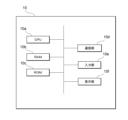
図2は、本実施形態に係るコンピュータ10の物理的構成を示す図である。コンピュータ10は、演算部に相当するCPU(Central Processing Unit)10aと、記憶部に相当するRAM(Random Access Memory)10bと、記憶部に相当するROM(Read only Memory)10cと、通信部10dと、入力部10eと、表示部10fと、を有する。これらの各構成は、バスを介して相互にデータ送受信可能に接続される。なお、本例ではコンピュータ10が一台のコンピュータで構成される場合について説明するが、コンピュータ10は、複数のコンピュータが組み合わされて実現されてもよい。また、図2で示す構成は一例であり、コンピュータ10はこれら以外の構成を有してもよいし、これらの構成のうち一部を有さなくてもよい。
Figure 2 is a diagram showing the physical configuration of the
CPU10aは、RAM10b又はROM10cに記憶されたプログラムの実行に関する制御やデータの演算、加工を行う制御部である。CPU10aは、ロボットを介したコミュニケーションを制御するプログラム(コミュニケーションプログラム)を実行する演算部である。CPU10aは、入力部10eや通信部10dから種々のデータを受け取り、データの演算結果を表示部10fに表示したり、RAM10bに格納したりする。
The
RAM10bは、記憶部のうちデータの書き換えが可能なものであり、例えば半導体記憶素子で構成されてよい。RAM10bは、CPU10aが実行するプログラム、ユーザ情報といったデータを記憶してよい。なお、これらは例示であって、RAM10bには、これら以外のデータが記憶されていてもよいし、これらの一部が記憶されていなくてもよい。
ROM10cは、記憶部のうちデータの読み出しが可能なものであり、例えば半導体記憶素子で構成されてよい。ROM10cは、例えばコミュニケーションプログラムや、書き換えが行われないデータを記憶してよい。
通信部10dは、コンピュータ10を他の機器に接続するインターフェースである。通信部10dは、インターネット等の通信ネットワークに接続されてよい。
The
入力部10eは、ユーザからの指示や情報の入力を受け付けるものであり、例えば、キーボード及びタッチパネルを含んでよい。また、入力部10eは、音声入力のためのマイクを含んでよい。
The
表示部10fは、CPU10aによる演算結果を視覚的に表示するものであり、例えば、LCD(Liquid Crystal Display)により構成されてよい。表示部10fは、ロボット20のカメラ20hで撮影された画像を表示してよい。また、表示部10fは、当該コンピュータ10が受信したメール、ショートメッセージ(SMS)、テキストメッセージ等を表示してよい。
The
この他、コンピュータ10は、当該コンピュータ10がメールやメッセージを受信した際に通知音を発生したり、受信したメールやメッセージを読み上げたりする音声出力部を有してよい。
In addition, the
コミュニケーションプログラムは、RAM10bやROM10c等のコンピュータによって読み取り可能な記憶媒体に記憶されて提供されてもよいし、通信部10dにより接続される通信ネットワークを介して提供されてもよい。コンピュータ10では、CPU10aがコミュニケーションプログラムを実行することにより、ロボット20を制御するための様々な動作が実現される。なお、これらの物理的な構成は例示であって、必ずしも独立した構成でなくてもよい。例えば、コンピュータ10は、CPU10aとRAM10bやROM10cが一体化したLSI(Large-Scale Integration)を備えていてもよい。
The communication program may be provided by being stored in a computer-readable storage medium such as
図3は、本実施形態に係るロボット20の物理的構成を示す図である。ロボット20は、演算部に相当するCPU20aと、記憶部に相当するRAM20bと、記憶部に相当するROM20cと、通信部20dと、入力部20eと、表示部20fと、駆動部20gと、カメラ20hとを有する。これらの各構成は、バスを介して相互にデータ送受信可能に接続される。なお、図3で示す構成は一例であり、ロボット20はこれら以外の構成を有してもよいし、これらの構成のうち一部を有さなくてもよい。
Figure 3 is a diagram showing the physical configuration of the
CPU20aは、RAM20b又はROM20cに記憶されたプログラムの実行に関する制御やデータの演算、加工を行う制御部である。CPU20aは、ロボットを介したコミュニケーションを制御するプログラム(コミュニケーションプログラム)を実行する演算部である。CPU20aは、入力部20eや通信部20dから種々のデータを受け取り、データの演算結果を表示部20fに表示したり、RAM20bに格納したりする。また、CPU20aは、駆動部20gを制御し、ロボット20の動作を制御する。
The
また、CPU20aは、当該ロボット20とコンピュータ10との間で通信接続が確立されていないときに、入力部20eへの入力に応じて、コンピュータ10に向けて呼び出し通知を送信する呼び出し部としての機能も有する。
The
RAM20bは、記憶部のうちデータの書き換えが可能なものであり、例えば半導体記憶素子で構成されてよい。RAM20bは、CPU20aが実行するプログラムを記憶してよい。なお、これらは例示であって、RAM20bには、これら以外のデータが記憶されていてもよいし、これらの一部が記憶されていなくてもよい。
ROM20cは、記憶部のうちデータの読み出しが可能なものであり、例えば半導体記憶素子で構成されてよい。ROM20cは、例えばコミュニケーションプログラムや、書き換えが行われないデータを記憶してよい。
通信部20dは、ロボット20を他の機器に接続するインターフェースである。通信部20dは、インターネット等の通信ネットワークに接続されてよい。
The
入力部20eは、ユーザからの指示や情報の入力を受け付けるものであり、例えば、タッチパネルを含んでよい。また、入力部20eは、音声入力のためのマイクを含んでよい。
The
表示部20fは、CPU20aによる演算結果を視覚的に表示するものであり、例えば、LCDにより構成されてよい。コンピュータ10がカメラを備える場合、表示部20fは、コンピュータ10のカメラで撮影された画像を表示してもよい。
The
駆動部20gは、遠隔操作可能なアクチュエータを含み、車輪等の移動部やマニピュレータ等を含む。ロボット20が移動型のロボットである場合、駆動部20gは、少なくとも車輪等の移動部を含むが、マニピュレータを含んでもよい。ロボット20が装着型である場合、駆動部20gは、少なくともマニピュレータを含む。
The
カメラ20hは、静止画又は動画を撮像する撮像素子を含み、撮像した静止画又は動画を、通信部20dを介してコンピュータ10に送信する。
The
コミュニケーションプログラムは、RAM20bやROM20c等のコンピュータによって読み取り可能な記憶媒体に記憶されて提供されてもよいし、通信部20dにより接続される通信ネットワークを介して提供されてもよい。ロボット20では、CPU20aがコミュニケーションプログラムを実行することにより、ロボット20を制御するための様々な動作が実現される。なお、これらの物理的な構成は例示であって、必ずしも独立した構成でなくてもよい。例えば、ロボット20は、CPU20aとRAM20bやROM20cが一体化したLSIを備えていてもよい。
The communication program may be provided by being stored in a computer-readable storage medium such as
図4は、本実施形態に係るコンピュータ10及びロボット20によりそれぞれ実行される処理のフローチャートである。図5は、本実施形態に係るロボット20に表示される画面例を示す図である。図6は、本実施形態に係るコンピュータ10に表示される画面例を示す図である。
Figure 4 is a flowchart of the processes executed by the
ロボット20は、コンピュータ10との通信接続が確立されていない間、コンピュータ10からの接続を待機する(S20)。
While a communication connection with the
ロボット20は、入力部20eへの入力操作を検知すると(S21:Yes)、予め登録された操作者名を表示部20fに表示する(S22)。ここで、予め登録された操作者名とは、当該ロボット20に認証情報が予め記憶された情報であり、当該ロボット20と通信(例えば、音声通話及びビデオ通話などの通話のための通信)が可能であるコンピュータを表す情報(例えばコンピュータの使用者や所有者等)である。ロボット20は、このような情報を、例えばアドレス帳のような形式で保持していてもよい。
When the
例えば、ロボット20は、入力部20eへのタップ操作に応じて、図5の(a)に例示するメニュー画面を表示する。そして、ロボット20は、メニュー画面のコールボタン201に対するタップ操作を検知すると、図5の(b)に例示する選択画面を表示する。選択画面には、予め登録された操作者名が表示されたアイコン202~205が表示されている。
For example, the
続いて、ロボット20は、任意の操作者が選択されたことを検知すると(S23:Yes)、選択された操作者のコンピュータ10に対し、呼び出し通知を送信する(S24)。ロボット20は、例えば、図5の(b)に示すアイコン202~205のうち、「Aさん」と表示されたアイコン202に対するタップ操作を検知すると、Aさんのコンピュータにメールやメッセージによる呼び出し通知を送信する。
Next, when the
コンピュータ10は、ロボット20から呼び出し通知を受信すると(S11:Yes)、受信した呼び出し通知を表示部10fに表示する(S12)。図6に例示する通知画面には、ロボット20から呼ばれている旨を示すテキストメッセージ101が表示されている。或いは、コンピュータ10は、呼び出し通知を受信した旨を示す着信音を発生してもよいし、テキストメッセージ101を音声読み上げしてもよい。また、コンピュータ10は、呼び出し元のロボット20に接続するためのリンクを含む接続ボタン102や、接続を拒否するキャンセルボタン103を通知画面に表示してもよい。
When the
コンピュータ10は、入力部10eにおいてロボット20との接続の指示を検知すると(S13:Yes)、ロボット20への接続処理を実行する(S14)。例えば、コンピュータ10は、図6に示す接続ボタン102に対するタップ操作を検知すると、接続処理(例えば、ロボット20との間の通話のための通信接続)を行う。接続処理には、ログイン認証処理等が含まれてもよい。なお、コンピュータ10は、呼び出し通知を受信しない場合であっても(S11:No)、入力部10eにおいて接続の指示を検知することにより、随時ロボット20と接続することができる。
When the
ロボット20は、コンピュータ10から接続要求を受けると(S25:Yes)、必要に応じて認証処理等を実行し、コンピュータ10と接続する(S26)。コンピュータ10と接続されている間、ロボット20は、コンピュータ10からの指令に基づいて動作する。ロボット20の表示部20fは、コンピュータ10との通話による通信接続の間、コンピュータ10のカメラで撮影された画像を表示してもよい。
When the
コンピュータ10は、入力部10eにおいてロボット20との切断の指示を検知すると(S15:Yes)、ロボット20との接続を切断する(S16)。その後、処理は終了する。ロボット20は、コンピュータ10からの接続が切断されると(S27:Yes)、処理を終了する。
When the
以上説明したように、本実施形態によれば、ロボット20が配置されている場所にいる現地のユーザ2は、遠隔操作者1がコンピュータ10をロボット20に接続してくれるのを待つだけでなく、ロボット20を操作してコンピュータ10に呼び出し通知を送信することにより、遠隔操作者1にロボット20への接続を促すことができる。従って、遠隔操作者1と現地のユーザ2の双方にとって利用し易いコミュニケーションシステムを実現することが可能となる。
As described above, according to this embodiment, the
(変形例1)
図7は、上記実施形態の変形例に係るロボット20に表示される画面例を示す図である。上記実施形態においては、ロボット20が入力部20eへの入力操作を検知した際に(S21:Yes)、予め登録された操作者名を表示部20fに表示することとしたが、認証を要することなく接続可能なコンピュータ10に関する情報を、インターネットを通じてロボット20側で検索できることとしてもよい。
(Variation 1)
7 is a diagram showing an example of a screen displayed on the
例えば、ロボット20は、入力部20eへのタップ操作に応じて、図7の(a)に例示するメニュー画面を表示する。そして、ロボット20は、メニュー画面において例えば「MARKET PLACE」と表示された選択ボタン211に対するタップ操作を検知すると、インターネットに接続して検索を行い、図7の(b)に例示するサービス選択画面を表示する。サービス選択画面には、ロボット20を介した提供が可能なサービスを示すアイコン212~215が表示されている。ロボット20を介した提供が可能なサービスとしては、例えば、医療相談サービスや英会話レッスンなどが挙げられる。或いは、掃除など特定の作業を伴うサービスであってもよい。
For example, the
ロボット20は、サービス選択画面において例えば「サービスY」と表示されたアイコン213に対するタップ操作を検知すると、図7の(c)に例示するプロバイダ選択画面を表示する。プロバイダ選択画面には、サービスYの提供業者を示すアイコン216~219が表示されている。そして、ロボット20は、プロバイダ選択画面において例えば「F社」と表示されたアイコン217に対するタップ操作を検知すると、図7の(d)に例示する確定画面を表示する。確定画面には、F社やF社が提供するサービスに関する詳細情報が示されている。
When the
さらに、ロボット20は、確定画面においてリクエストボタン220に対するタップ操作を検知すると、F社のコンピュータ10に向けて呼び出し通知を送信する。F社のコンピュータ10は、ロボット20からの呼び出し通知を受信すると、ロボット20に接続する処理を実行する。なお、呼び出し通知を受信したコンピュータ10が、ロボット20に接続する権限を有していない場合、所定の範囲の権限が当該コンピュータ10に自動的に付与されるようにしてもよい。
Furthermore, when the
(変形例2)
上記実施形態においては、ロボット20の表示部20fに表示された画面に対する操作に応じて、通信可能なコンピュータの中から選択されたコンピュータに呼び出し通知を送信することとしたが、ロボット20に対する音声入力に応じて呼び出し通知を送信することとしてもよい。この場合、CPU20aは、音声入力のためのマイクから入力された音声を認識してテキストに変換する音声認識部としての機能も有する。
(Variation 2)
In the above embodiment, a call notification is sent to a computer selected from among computers with which the
例えば、ロボット20は、「助けて」といった特定の音声を認識すると、緊急用として予め設定されたコンピュータ10に呼び出し通知を送信する。緊急用のコンピュータとしては、現地のユーザ2の家族が使用するコンピュータや、かかりつけ医のコンピュータ等が挙げられる。
For example, when the
(変形例3)
上記の実施形態において、コンピュータ10は、呼び出し通知を受信した旨がコンピュータ10の表示部10fに表示された場合、入力部10eへの入力に応じて、ロボット20との通話のための通信の接続処理を実行した。変形例として、コンピュータ10は、呼び出し通知を受信した旨がコンピュータ10の表示部10fに表示された後、入力部10eへの入力に応じて、呼び出し通知に対する応答通知をロボット20に送信してもよい。ロボット20は、コンピュータ10から受信した応答通知に応じたメッセージを(ロボット20の前にいる)ユーザに提示することができる。応答通知に応じたメッセージは、例えば、ロボット20のスピーカから出力される音声メッセージ、又はロボット20の表示部に表示されるテキスト若しくは画像のメッセージを含む。当該メッセージは、「もう少し待って」、「今接続するよ」などを含む。コンピュータ10は、応答通知の送信の後、入力部10eへの入力に応じて、ロボット20との通話のための通信の接続処理を実行してもよい。
(Variation 3)
In the above embodiment, when the
以上説明した実施形態及び変形例は、本発明の理解を容易にするためのものであり、本発明を限定して解釈するためのものではない。実施形態及び変形例が備える各要素並びにその配置、材料、条件、形状及びサイズ等は、例示したものに限定されるわけではなく適宜変更することができる。また、異なる実施形態及び変形例で示した構成同士を部分的に置換し又は組み合わせることが可能である。 The above-described embodiments and modifications are intended to facilitate understanding of the present invention, and are not intended to limit the present invention. The elements of the embodiments and modifications, as well as their arrangements, materials, conditions, shapes, sizes, etc., are not limited to those exemplified, and may be modified as appropriate. In addition, configurations shown in different embodiments and modifications may be partially substituted or combined.
1…遠隔操作者、2…現地のユーザ、10…コンピュータ、20…ロボット、10a,20a…CPU、10b,20b…RAM、10c,20c…ROM、10d,20d…通信部、10e,20e…入力部、10f,20f…表示部、20g…駆動部、20b…RAM、20h…カメラ、100…コミュニケーションシステム、101…テキストメッセージ、102…接続ボタン、103…キャンセルボタン、201…コールボタン、202~205,212~219…アイコン、211…選択ボタン、220…リクエストボタン 1...Remote operator, 2...Local user, 10...Computer, 20...Robot, 10a, 20a...CPU, 10b, 20b...RAM, 10c, 20c...ROM, 10d, 20d...Communication unit, 10e, 20e...Input unit, 10f, 20f...Display unit, 20g...Drive unit, 20b...RAM, 20h...Camera, 100...Communication system, 101...Text message, 102...Connect button, 103...Cancel button, 201...Call button, 202-205, 212-219...Icon, 211...Select button, 220...Request button
Claims (6)
前記ロボットは、
カメラと、
前記コンピュータによる遠隔操作が可能な駆動部と、
当該ロボットに対する指示を入力する第1の入力部と、
前記コンピュータとの間で通信接続が確立されていないときに、前記第1の入力部に入力された指示に応じて、前記コンピュータに向けて呼び出し通知を送信する呼び出し部と、を有し、
前記コンピュータは、
前記ロボットに対する指令を入力する第2の入力部と、
前記カメラで撮影された画像を表示すると共に、前記ロボットから前記呼び出し通知を受信した場合に、該通知を受信した旨を表示する表示部と、を有する、
コミュニケーションシステムにおいて、
前記ロボットは、当該ロボットと通信可能な少なくとも1つのコンピュータを表す情報を記憶する記憶部をさらに有し、
前記呼び出し部は、前記少なくとも1つのコンピュータを表す情報のうち、前記第1の入力部への入力に応じて選択された情報に対応するコンピュータに、前記呼び出し通知を送信する、
コミュニケーションシステム。 A communication system comprising a non-fixed robot and a computer capable of communicating with the robot,
The robot comprises:
Camera and
A drive unit that can be remotely controlled by the computer;
A first input unit that inputs an instruction to the robot;
a calling unit that transmits a call notification to the computer in response to an instruction input to the first input unit when a communication connection with the computer is not established,
The computer includes:
a second input unit for inputting a command for the robot;
a display unit that displays an image captured by the camera and, when the call notification is received from the robot, displays a message indicating that the notification has been received.
In the communication system,
The robot further includes a storage unit that stores information representing at least one computer that can communicate with the robot;
the calling unit transmits the call notification to a computer corresponding to information selected in response to the input to the first input unit from among the information representing the at least one computer.
Communication system .
前記呼び出し部は、検索された前記情報のうち前記第1の入力部への入力に応じて選択された情報に対応するコンピュータに、前記呼び出し通知を送信する、
請求項1又は2に記載のコミュニケーションシステム。 The robot connects to the Internet in response to an input to the first input unit, and searches for information about a computer that can be connected to the robot;
the calling unit transmits the call notification to a computer corresponding to information selected from the searched information in response to the input to the first input unit.
3. A communication system according to claim 1 or 2.
前記ロボットは、前記第1の入力部に入力された音声を認識してテキストに変換する音声認識部をさらに有し、
前記呼び出し部は、前記第1の入力部に特定のテキストを含む音声が入力された場合に、前記少なくとも1つのコンピュータのうち予め設定されたコンピュータに前記呼び出し通知を送信する、
請求項1又は2に記載のコミュニケーションシステム。 the first input unit is a voice input unit that accepts voice input,
The robot further includes a voice recognition unit that recognizes a voice input to the first input unit and converts the voice into text,
the calling unit transmits the call notification to a preset computer among the at least one computer when a voice including specific text is input to the first input unit.
3. A communication system according to claim 1 or 2.
前記ロボットは、前記コンピュータから受信した前記応答通知に応じたメッセージをユーザに提示する、請求項1から4のいずれか一項に記載のコミュニケーションシステム。 when the display unit displays the receipt of the call notification, the computer transmits a response notification to the robot in response to the input to the second input unit, and then establishes a communication connection for a call with the robot;
The communication system according to claim 1 , wherein the robot presents a message to the user in response to the response notification received from the computer.
コンピュータによる遠隔操作が可能な駆動部と、
当該ロボットに対する指示を入力する入力部と、
前記コンピュータとの間で通信接続が確立されていないときに、前記入力部への入力に応じて、前記コンピュータに向けて呼び出し通知を送信する呼び出し部と、
当該ロボットと通信可能な少なくとも1つのコンピュータを表す情報を記憶する記憶部と、
を有し、
前記呼び出し部は、前記少なくとも1つのコンピュータを表す情報のうち、前記入力部への入力に応じて選択された情報に対応するコンピュータに、前記呼び出し通知を送信する、
ロボット。 A mobile or wearable robot that can be worn by a person ,
A drive unit that can be remotely controlled by a computer;
an input unit for inputting instructions to the robot;
a calling unit that transmits a call notification to the computer in response to an input to the input unit when a communication connection with the computer is not established;
A storage unit that stores information representing at least one computer that can communicate with the robot;
having
the calling unit transmits the call notification to a computer corresponding to information selected in response to the input to the input unit from among the information representing the at least one computer.
robot.
Priority Applications (1)
| Application Number | Priority Date | Filing Date | Title |
|---|---|---|---|
| JP2020151865A JP7591891B2 (en) | 2020-09-10 | 2020-09-10 | Communication Systems and Robots |
Applications Claiming Priority (1)
| Application Number | Priority Date | Filing Date | Title |
|---|---|---|---|
| JP2020151865A JP7591891B2 (en) | 2020-09-10 | 2020-09-10 | Communication Systems and Robots |
Publications (2)
| Publication Number | Publication Date |
|---|---|
| JP2022046036A JP2022046036A (en) | 2022-03-23 |
| JP7591891B2 true JP7591891B2 (en) | 2024-11-29 |
Family
ID=80779748
Family Applications (1)
| Application Number | Title | Priority Date | Filing Date |
|---|---|---|---|
| JP2020151865A Active JP7591891B2 (en) | 2020-09-10 | 2020-09-10 | Communication Systems and Robots |
Country Status (1)
| Country | Link |
|---|---|
| JP (1) | JP7591891B2 (en) |
Citations (9)
| Publication number | Priority date | Publication date | Assignee | Title |
|---|---|---|---|---|
| JP2004114178A (en) | 2002-09-24 | 2004-04-15 | Honda Motor Co Ltd | Reception guide robot |
| JP2007190641A (en) | 2006-01-19 | 2007-08-02 | Advanced Telecommunication Research Institute International | Communication robot |
| JP2009083051A (en) | 2007-09-28 | 2009-04-23 | Sogo Keibi Hosho Co Ltd | Autonomous mobile body, monitoring system, and communication method |
| JP2009241166A (en) | 2008-03-28 | 2009-10-22 | Advanced Telecommunication Research Institute International | Robot remote operation system |
| JP2010213127A (en) | 2009-03-12 | 2010-09-24 | Broad Service Co Ltd | Call center reception system |
| JP2018050161A (en) | 2016-09-21 | 2018-03-29 | 公立大学法人首都大学東京 | Communication system |
| JP2019095795A (en) | 2014-12-25 | 2019-06-20 | エイディシーテクノロジー株式会社 | In-vehicle machine |
| JP2019124855A (en) | 2018-01-18 | 2019-07-25 | 株式会社ユピテル | Apparatus and program and the like |
| JP2020066094A (en) | 2018-10-24 | 2020-04-30 | トヨタ自動車株式会社 | Communication robot and communication robot control program |
-
2020
- 2020-09-10 JP JP2020151865A patent/JP7591891B2/en active Active
Patent Citations (9)
| Publication number | Priority date | Publication date | Assignee | Title |
|---|---|---|---|---|
| JP2004114178A (en) | 2002-09-24 | 2004-04-15 | Honda Motor Co Ltd | Reception guide robot |
| JP2007190641A (en) | 2006-01-19 | 2007-08-02 | Advanced Telecommunication Research Institute International | Communication robot |
| JP2009083051A (en) | 2007-09-28 | 2009-04-23 | Sogo Keibi Hosho Co Ltd | Autonomous mobile body, monitoring system, and communication method |
| JP2009241166A (en) | 2008-03-28 | 2009-10-22 | Advanced Telecommunication Research Institute International | Robot remote operation system |
| JP2010213127A (en) | 2009-03-12 | 2010-09-24 | Broad Service Co Ltd | Call center reception system |
| JP2019095795A (en) | 2014-12-25 | 2019-06-20 | エイディシーテクノロジー株式会社 | In-vehicle machine |
| JP2018050161A (en) | 2016-09-21 | 2018-03-29 | 公立大学法人首都大学東京 | Communication system |
| JP2019124855A (en) | 2018-01-18 | 2019-07-25 | 株式会社ユピテル | Apparatus and program and the like |
| JP2020066094A (en) | 2018-10-24 | 2020-04-30 | トヨタ自動車株式会社 | Communication robot and communication robot control program |
Non-Patent Citations (3)
| Title |
|---|
| アバター使い遠隔で家族間コミュニケーション、大分県とANAHDが実証実験,[online],2019年05月30日,[2024年10月31日検索],インターネット<URL:https://project.nikkeibp.co.jp/atclppp/PPP/news/053001175/> |
| 人工知能ではなく人の繋がりで、人の孤独を解消する若きロボットコミュニケーターの挑戦[第1回],[online],2018年01月31日,[2024年10月31日検索],インターネット<URL:https://www.okamura.co.jp/magazine/wave/archive/1801yoshifujiA.html> |
| 遠隔操作で相手と会話可能な自走式ロボット「Beam+」が破格の10万円台で予約受付中,[online],2014年01月16日,[2024年10月31日検索],インターネット<URL:https://gigazine.net/news/20140116-beam-plus/> |
Also Published As
| Publication number | Publication date |
|---|---|
| JP2022046036A (en) | 2022-03-23 |
Similar Documents
| Publication | Publication Date | Title |
|---|---|---|
| JP5849484B2 (en) | Transmission terminal, display data transmission method, program, information providing apparatus, and transmission system | |
| JP2017147555A (en) | Information terminal, program, communication control method, and communication system | |
| US10341519B2 (en) | Communication system, image forming apparatus, method of controlling the same, and storage medium | |
| KR20110003964A (en) | System and method for multi-screen service of mobile terminal | |
| JP2015106292A (en) | Information processor, system, and control method for information processor | |
| JP7591891B2 (en) | Communication Systems and Robots | |
| WO2023053446A1 (en) | Communication system and robot | |
| JP7652548B2 (en) | Communication system and terminal device | |
| JP2024034388A (en) | Chatbot control system, chatbot control method, and program | |
| US10250845B1 (en) | Remote collaboration system with projector-camera based robot device and head mounted display, and remote interaction method using the same | |
| JP7561388B2 (en) | Computer, program, system and information processing method | |
| JP2022077483A (en) | Program, method, and information processing device | |
| JP2016178355A (en) | Communication device, communication system, communication device control method, and program | |
| JP6766541B2 (en) | Operation control program, operation control method and information processing device | |
| JP7525343B2 (en) | Payment system and payment method | |
| US20240143265A1 (en) | Program, method, and information processing device | |
| JP2019201322A (en) | Remote maintenance system and information processing method | |
| JP2024121405A (en) | Information processing device, information processing method, and program | |
| CN117997888A (en) | Communication interaction method, device, equipment, storage medium and chip | |
| JP2024024297A (en) | Programs, computers, systems and information processing methods | |
| JP7041030B2 (en) | Communication systems and programs | |
| US20060215696A1 (en) | Information processing device linkage apparatus, information processing device linkage system, and information processing device linkage program | |
| KR101434616B1 (en) | Communication method and network display device using the same | |
| JP2023184432A (en) | Telepresence robot system, information processing device, information processing method, and program | |
| JP2024054420A (en) | COMMUNICATION SYSTEM, COMMUNICATION METHOD, AND PROGRAM |
Legal Events
| Date | Code | Title | Description |
|---|---|---|---|
| A521 | Request for written amendment filed |
Free format text: JAPANESE INTERMEDIATE CODE: A523 Effective date: 20200916 |
|
| A521 | Request for written amendment filed |
Free format text: JAPANESE INTERMEDIATE CODE: A523 Effective date: 20200917 |
|
| A621 | Written request for application examination |
Free format text: JAPANESE INTERMEDIATE CODE: A621 Effective date: 20230802 |
|
| A977 | Report on retrieval |
Free format text: JAPANESE INTERMEDIATE CODE: A971007 Effective date: 20240610 |
|
| A131 | Notification of reasons for refusal |
Free format text: JAPANESE INTERMEDIATE CODE: A131 Effective date: 20240730 |
|
| A521 | Request for written amendment filed |
Free format text: JAPANESE INTERMEDIATE CODE: A523 Effective date: 20240927 |
|
| TRDD | Decision of grant or rejection written | ||
| A01 | Written decision to grant a patent or to grant a registration (utility model) |
Free format text: JAPANESE INTERMEDIATE CODE: A01 Effective date: 20241106 |
|
| A61 | First payment of annual fees (during grant procedure) |
Free format text: JAPANESE INTERMEDIATE CODE: A61 Effective date: 20241119 |
|
| R150 | Certificate of patent or registration of utility model |
Ref document number: 7591891 Country of ref document: JP Free format text: JAPANESE INTERMEDIATE CODE: R150 |