JP6635086B2 - Manufacturing method of hot-dip galvanized steel strip - Google Patents
Manufacturing method of hot-dip galvanized steel strip Download PDFInfo
- Publication number
- JP6635086B2 JP6635086B2 JP2017075451A JP2017075451A JP6635086B2 JP 6635086 B2 JP6635086 B2 JP 6635086B2 JP 2017075451 A JP2017075451 A JP 2017075451A JP 2017075451 A JP2017075451 A JP 2017075451A JP 6635086 B2 JP6635086 B2 JP 6635086B2
- Authority
- JP
- Japan
- Prior art keywords
- steel strip
- gas
- molten metal
- hot
- nozzle
- Prior art date
- Legal status (The legal status is an assumption and is not a legal conclusion. Google has not performed a legal analysis and makes no representation as to the accuracy of the status listed.)
- Active
Links
- 238000004519 manufacturing process Methods 0.000 title claims description 27
- 229910001335 Galvanized steel Inorganic materials 0.000 title claims description 12
- 239000008397 galvanized steel Substances 0.000 title claims description 12
- 229910000831 Steel Inorganic materials 0.000 claims description 118
- 239000010959 steel Substances 0.000 claims description 118
- 238000007747 plating Methods 0.000 claims description 58
- 239000002184 metal Substances 0.000 claims description 48
- 229910052751 metal Inorganic materials 0.000 claims description 48
- 238000000034 method Methods 0.000 claims description 20
- 239000012535 impurity Substances 0.000 claims description 3
- -1 Al: 1.0 to 10 mass% Substances 0.000 claims 1
- 238000007664 blowing Methods 0.000 claims 1
- 239000007789 gas Substances 0.000 description 65
- 230000037303 wrinkles Effects 0.000 description 41
- XLYOFNOQVPJJNP-UHFFFAOYSA-N water Substances O XLYOFNOQVPJJNP-UHFFFAOYSA-N 0.000 description 35
- 238000002347 injection Methods 0.000 description 7
- 239000007924 injection Substances 0.000 description 7
- 239000011248 coating agent Substances 0.000 description 6
- 238000000576 coating method Methods 0.000 description 6
- 230000000694 effects Effects 0.000 description 5
- 210000004894 snout Anatomy 0.000 description 5
- 230000007547 defect Effects 0.000 description 4
- 239000000203 mixture Substances 0.000 description 4
- 230000003647 oxidation Effects 0.000 description 4
- 238000007254 oxidation reaction Methods 0.000 description 4
- 238000000137 annealing Methods 0.000 description 3
- 238000001816 cooling Methods 0.000 description 3
- 239000011261 inert gas Substances 0.000 description 3
- 238000005259 measurement Methods 0.000 description 3
- 230000008569 process Effects 0.000 description 3
- 238000005096 rolling process Methods 0.000 description 3
- 229910018137 Al-Zn Inorganic materials 0.000 description 2
- 229910018573 Al—Zn Inorganic materials 0.000 description 2
- XKRFYHLGVUSROY-UHFFFAOYSA-N Argon Chemical compound [Ar] XKRFYHLGVUSROY-UHFFFAOYSA-N 0.000 description 2
- IJGRMHOSHXDMSA-UHFFFAOYSA-N Atomic nitrogen Chemical compound N#N IJGRMHOSHXDMSA-UHFFFAOYSA-N 0.000 description 2
- CURLTUGMZLYLDI-UHFFFAOYSA-N Carbon dioxide Chemical compound O=C=O CURLTUGMZLYLDI-UHFFFAOYSA-N 0.000 description 2
- 230000008901 benefit Effects 0.000 description 2
- 230000008859 change Effects 0.000 description 2
- 230000000052 comparative effect Effects 0.000 description 2
- 238000002474 experimental method Methods 0.000 description 2
- 238000005246 galvanizing Methods 0.000 description 2
- 230000003746 surface roughness Effects 0.000 description 2
- 238000012360 testing method Methods 0.000 description 2
- 229910052786 argon Inorganic materials 0.000 description 1
- 239000001569 carbon dioxide Substances 0.000 description 1
- 229910002092 carbon dioxide Inorganic materials 0.000 description 1
- 230000007423 decrease Effects 0.000 description 1
- 238000010586 diagram Methods 0.000 description 1
- 238000011156 evaluation Methods 0.000 description 1
- 239000001307 helium Substances 0.000 description 1
- 229910052734 helium Inorganic materials 0.000 description 1
- SWQJXJOGLNCZEY-UHFFFAOYSA-N helium atom Chemical compound [He] SWQJXJOGLNCZEY-UHFFFAOYSA-N 0.000 description 1
- 238000007689 inspection Methods 0.000 description 1
- 230000007246 mechanism Effects 0.000 description 1
- 238000002844 melting Methods 0.000 description 1
- 230000008018 melting Effects 0.000 description 1
- 229910052757 nitrogen Inorganic materials 0.000 description 1
- 238000005554 pickling Methods 0.000 description 1
- 238000001953 recrystallisation Methods 0.000 description 1
- 230000009467 reduction Effects 0.000 description 1
- 239000007921 spray Substances 0.000 description 1
- 239000000126 substance Substances 0.000 description 1
- 239000002344 surface layer Substances 0.000 description 1
- 229910052725 zinc Inorganic materials 0.000 description 1
Images


Landscapes
- Coating With Molten Metal (AREA)
Description
本発明は、溶融金属めっき鋼帯の製造方法に関し、特に、鋼帯表面の溶融金属の付着量(以下、「めっき付着量」ともいう。)を調整するガスワイピングに関するものである。 The present invention relates to a method for producing a hot-dip metal-plated steel strip, and more particularly to gas wiping for adjusting the amount of hot-metal deposited on the surface of a steel strip (hereinafter, also referred to as “plated coating amount”).
連続溶融金属めっきラインでは、図1に示すように、還元雰囲気の連続焼鈍炉で焼鈍された鋼帯Sは、スナウト10内を通過して、めっき槽12内の溶融金属浴14中に連続的に導入される。その後鋼帯Sは、溶融金属浴14中のシンクロール16、サポートロール18を介して溶融金属浴14の上方に引き上げられ、ガスワイピングノズル20A,20Bで所定のめっき厚みに調整された後に、冷却されて後工程に導かれる。ガスワイピングノズル20A,20Bは、めっき槽12上方に、鋼帯Sを挟んで対向して配置され、その噴射口から鋼帯Sの両面に向けてガスを吹き付ける。このガスワイピングにより、余剰な溶融金属が掻き取られて、鋼帯表面のめっき付着量が調整されるとともに、鋼帯表面に付着した溶融金属が板幅方向及び板長手方向で均一化される。ガスワイピングノズル20A,20Bは、多様な鋼帯幅に対応するとともに、鋼帯引き上げ時の幅方向の位置ズレなどに対応するため、通常、鋼帯幅より幅広く構成され、鋼帯の幅方向端部より外側まで延びている。
In the continuous molten metal plating line, as shown in FIG. 1, the steel strip S annealed in the continuous annealing furnace in the reducing atmosphere passes through the
このようなガスワイピング方式では、(1)ワイピングガスの衝突圧力の振動、(2)溶融金属の酸化/冷却による粘度ムラ、の一方又は両方に起因して、製造された溶融金属めっき鋼帯のめっき表面に波形流紋状の湯ジワ(湯ダレ)が発生しやすい。このような湯ジワが生じためっき鋼板は、外装板の用途において、そのめっき表面を塗装下地表面とした場合に、塗膜の表面性状、特に平滑性を阻害する。そのため、湯ジワが生じためっき鋼板は、外観の優れた塗装処理が求められる外装板に用いることができず、めっき鋼板の歩留まりに大きな影響を及ぼす。 In such a gas wiping method, one or both of (1) the vibration of the collision pressure of the wiping gas and (2) the unevenness in the viscosity due to oxidation / cooling of the molten metal causes the produced molten metal-plated steel strip to be produced. Wavy wrinkles in the shape of a wave pattern are easily generated on the plating surface. The plated steel sheet having such hot water wrinkles impairs the surface properties, particularly the smoothness, of the coating film when the plating surface is used as a coating base surface in the use of an exterior plate. For this reason, the plated steel sheet having the hot water wrinkles cannot be used as an exterior sheet requiring a coating treatment with excellent appearance, which greatly affects the yield of the plated steel sheet.
湯ジワというめっき表面欠陥を抑制する方法としては、以下の方法が知られている。特許文献1には、めっき後の工程である調質圧延に際して、調質圧延ロールの表面性状や圧延条件を変えることで、湯ジワを目立たなくする方法が記載されている。特許文献2には、鋼板を溶融亜鉛めっき浴中に導入する前に、スキンパスミル及びテンションレベラー等を用いて鋼板表面の粗さをめっき付着量に応じて調整して、湯ジワの発生を抑制する方法が記載されている。 The following methods are known as methods for suppressing plating surface defects called hot water wrinkles. Patent Literature 1 describes a method of making surface wrinkles less noticeable by changing the surface properties and rolling conditions of a temper rolling roll during temper rolling, which is a step after plating. Patent Document 2 discloses that before introducing a steel sheet into a hot-dip galvanizing bath, the surface roughness of the steel sheet is adjusted using a skin pass mill, a tension leveler or the like in accordance with the amount of coating to suppress the occurrence of hot water wrinkles. A method is described.
しかしながら、本発明者らが検討したところによれば、特許文献1に示された方法では、軽微な湯ジワは改善されるが、重度の湯ジワに対しては効果が見られなかった。また、特許文献2に示された方法では、溶融亜鉛めっき浴の前工程にスキンパスミル、テンションレベラー等を設置する必要性からコスト的な問題がある。また、これらを設置した場合も、前処理設備及び焼鈍炉での酸洗及び再結晶化に伴う亜鉛めっき被膜の化学的・物理的変化によって、理想とする表面粗度が得られにくく、湯ジワ発生を十分に抑制することが困難であると考えられる。 However, according to studies by the present inventors, the method disclosed in Patent Document 1 improves minor hot water wrinkles, but has no effect on severe hot water wrinkles. In addition, the method disclosed in Patent Document 2 has a problem in cost due to the necessity of installing a skin pass mill, a tension leveler, and the like in a pre-process of a hot-dip galvanizing bath. In addition, even when these are installed, it is difficult to obtain the ideal surface roughness due to the chemical and physical changes of the galvanized film due to the pickling and recrystallization in the pretreatment equipment and the annealing furnace, and the hot water It is considered that it is difficult to sufficiently suppress the occurrence.
そこで本発明は、上記課題に鑑み、湯ジワの発生を十分に抑え、高品質の溶融金属めっき鋼帯を低コストで製造可能な溶融金属めっき鋼帯の製造方法を提供することを目的とする。 In view of the above problems, an object of the present invention is to provide a method of manufacturing a hot-dip metal-plated steel strip that can sufficiently suppress the generation of hot water wrinkles and can manufacture a high-quality hot-dip metal-plated steel strip at low cost. .
上記課題を解決するべく本発明者らが鋭意検討したところ、ガスワイピングノズルのヘッダ圧力とガス衝突圧変動量との間に正の線形相関があること、すなわち、ヘッダ圧力を制御することによってガスの衝突圧変動量を制御できることを初めて見出した。そして、ガスの衝突圧変動量を、鋼帯の走行速度及び目標のめっき厚さを考慮して、所定の値に設定することによって、湯ジワの発生を十分に抑えることができるとの知見を得た。 The present inventors have conducted intensive studies to solve the above-described problems, and found that there is a positive linear correlation between the header pressure of the gas wiping nozzle and the amount of gas collision pressure fluctuation, that is, by controlling the header pressure, It was found for the first time that the amount of fluctuation in the collision pressure could be controlled. By setting the gas collision pressure fluctuation amount to a predetermined value in consideration of the running speed of the steel strip and the target plating thickness, it has been found that generation of hot water wrinkles can be sufficiently suppressed. Obtained.
上記知見に基づき完成された本発明の要旨構成は以下のとおりである。
[1]溶融金属浴に連続的に鋼帯を浸漬し、
前記溶融金属浴から引き上げられる鋼帯に、該鋼帯を挟んで配置される一対のガスワイピングノズルからガスを吹き付けて、該鋼帯の両面の溶融金属の付着量を調整して、
連続的に溶融金属めっき鋼帯を製造する溶融金属めっき鋼帯の製造方法であって、
前記ガスの衝突圧変動量σを、前記鋼帯の走行速度L及び目標のめっき厚さWに応じて、以下の式(1)を満足するように制御することを特徴とする、溶融金属めっき鋼帯の製造方法。

L:鋼帯の走行速度[m/min]
W:目標のめっき厚さ[μm]
α,β:定数
The gist configuration of the present invention completed on the basis of the above findings is as follows.
[1] A steel strip is continuously immersed in a molten metal bath,
Gas is blown from a pair of gas wiping nozzles disposed on the steel strip with the steel strip interposed between the steel strip pulled up from the molten metal bath, and the amount of molten metal deposited on both surfaces of the steel strip is adjusted.
A method for manufacturing a hot-dip metal-plated steel strip for continuously manufacturing a hot-dip metal-plated steel strip,
The molten metal plating is characterized in that the collision pressure fluctuation amount σ of the gas is controlled so as to satisfy the following expression (1) according to the running speed L of the steel strip and the target plating thickness W. Steel strip manufacturing method.
L: Running speed of steel strip [m / min]
W: Target plating thickness [μm]
α, β: constant
[2]前記ガスワイピングノズルのヘッダ圧力P[kPa]と、前記ガスの衝突圧変動量σとの関係を予め求め、
前記ガスの衝突圧変動量σが式(1)を満足するように前記ヘッダ圧力Pを設定する、上記[1]に記載の溶融金属めっき鋼帯の製造方法。
[2] The relation between the header pressure P [kPa] of the gas wiping nozzle and the collision pressure fluctuation amount σ of the gas is obtained in advance,
The method for producing a hot-dip metal-plated steel strip according to the above [1], wherein the header pressure P is set such that the collision pressure fluctuation amount σ of the gas satisfies Expression (1).
[3]前記ガスワイピングノズルの先端の高さを、前記溶融金属浴の表面から250mm以下とする、上記[1]又は[2]に記載の溶融金属めっき鋼帯の製造方法。 [3] The method for producing a hot-dip metal-plated steel strip according to the above [1] or [2], wherein a height of a tip of the gas wiping nozzle is 250 mm or less from a surface of the hot-dip metal bath.
[4]前記鋼帯の幅方向端部近傍の鋼帯延長面上に、前記一対のガスワイピングノズルから噴射されたガス同士の衝突を回避するバッフルプレートを設置する、上記[1]〜[3]のいずれか一項に記載の溶融金属めっき鋼帯の製造方法。 [4] A baffle plate for avoiding collision between gases injected from the pair of gas wiping nozzles is installed on a steel strip extension surface near an end in the width direction of the steel strip, [1] to [3]. ] The manufacturing method of the hot-dip metal-plated steel strip as described in any one of the above.
[5]前記溶融金属の成分は、Al:1.0〜10質量%、Mg:0.2〜1質量%、Ni:0〜0.1質量%を含有し、残部がZn及び不可避的不純物からなる、上記[1]〜[4]のいずれか一項に記載の溶融金属めっき鋼帯の製造方法。 [5] The above-mentioned [1] wherein the component of the molten metal contains 1.0 to 10% by mass of Al, 0.2 to 1% by mass of Mg, and 0 to 0.1% by mass of Ni, with the balance being Zn and unavoidable impurities. ] The manufacturing method of the hot-dip metal-plated steel strip as described in any one of-[4].
本発明の溶融金属めっき鋼帯の製造方法によれば、湯ジワの発生を十分に抑え、高品質の溶融金属めっき鋼帯を低コストで製造できる。 ADVANTAGE OF THE INVENTION According to the manufacturing method of the hot-dip metal-plated steel strip of this invention, generation | occurrence | production of hot water wrinkles is fully suppressed, and a high-quality hot-dip metal-plated steel strip can be manufactured at low cost.
図1を参照して、本発明の一実施形態による溶融金属めっき鋼帯の製造方法で使用可能な連続溶融金属めっき設備100(以下、単に「めっき設備」とも称する。)を説明する。 With reference to FIG. 1, a continuous hot-dip metal plating facility 100 (hereinafter, also simply referred to as “plating facility”) that can be used in the method for producing a hot-dip metal-plated steel strip according to one embodiment of the present invention will be described.
図1を参照して、本実施形態のめっき設備100は、スナウト10と、溶融金属を収容するめっき槽12と、シンクロール16と、サポートロール18とを有する。スナウト10は、鋼帯Sが通過する空間を区画する、鋼帯進行方向に垂直な断面が矩形状の部材であり、その先端は、めっき槽12に形成される溶融金属浴14に浸漬されている。一実施形態において、還元雰囲気の連続焼鈍炉で焼鈍された鋼帯Sは、スナウト10内を通過して、めっき槽12内の溶融金属浴14中に連続的に導入される。その後鋼帯Sは、溶融金属浴14中のシンクロール16、サポートロール18を介して溶融金属浴14の上方に引き上げられ、一対のガスワイピングノズル20A,20Bで所定のめっき厚みに調整された後に、冷却されて後工程に導かれる。
Referring to FIG. 1, a
一対のガスワイピングノズル20A,20B(以下、単に「ノズル」ともいう。)は、めっき槽12上方に、鋼帯Sを挟んで対向して配置される。図1に加えて図2も参照して、ノズル20Aは、その先端で鋼帯の板幅方向に延在する噴射口26(ノズルスリット)から鋼帯Sに向けてガスを吹き付け、鋼帯の表面のめっき付着量を調整する。他方のノズル20Bも同様であり、これら一対のノズル20A,20Bによって、余剰な溶融金属が掻き取られて、鋼帯Sの両面のめっき付着量が調整され、かつ、板幅方向及び板長手方向で均一化される。
The pair of
ノズル20A,20Bは、多様な鋼帯幅に対応するとともに、鋼帯引き上げ時の幅方向の位置ズレなどに対応するため、通常、鋼帯幅より長く構成され、鋼帯の幅方向端部より外側まで延びている。また、図2に示すように、ノズル20Aは、ノズルヘッダ22と、このノズルヘッダ22に連結された上ノズル部材24A及び下ノズル部材24Bとを有する。上下ノズル部材24A,24Bの先端部分は、鋼帯Sに垂直な断面視で互いに平行に対向する面を有し、これによりガスの噴射口26(ノズルスリット)を形成している。噴射口26は、鋼帯Sの板幅方向に延在している。ノズル20Aの縦断面形状は、先端に向かって先細りするテーパ形状となっている。上下ノズル部材24A,24Bの先端部の厚みは、1〜3mm程度とすればよい。また、噴射口の開口幅(ノズルギャップB)は、特に限定されないが0.5〜3.0mm程度とすることができる。図示しないガス供給機構から供給されるガスが、ヘッダ22の内部を通過し、さらに上下ノズル部材24A,24Bが区画するガス流路を通過し、噴射口26から噴射されて、鋼帯Sの表面に吹きつけられる。他方のノズル20Bも同様の構成を有する。本発明において、ノズルヘッダ22内でのガスの圧力を「ヘッダ圧力P」と定義する。
The
本実施形態の溶融金属めっき鋼帯の製造方法では、溶融金属浴14に連続的に鋼帯Sを浸漬し、溶融金属浴14から引き上げられる鋼帯Sに、該鋼帯Sを挟んで配置される一対のガスワイピングノズル20A,20Bからガスを吹き付けて、鋼帯Sの両面の溶融金属の付着量を調整して、連続的に溶融金属めっき鋼帯を製造するものである。
In the method for manufacturing a hot-dip metal-plated steel strip of the present embodiment, the steel strip S is continuously immersed in the hot-
ここで、上記で説明した湯ジワの発生原因としては、ワイピングガスが溶融金属表面に衝突する点(淀み点)での初期凹凸の生成が挙げられる。初期凹凸の生成原因は、(1)ワイピングガスの衝突圧力の振動、(2)溶融金属の酸化/冷却による粘度ムラ、の一方又は両方に起因して、鋼帯上で溶融金属が不規則に流れることであると考えられる。本発明は、このうち上記(1)の現象を抑えることによって、湯ジワの発生を抑制しようとするものである。 Here, as a cause of the occurrence of hot water wrinkles described above, generation of initial irregularities at a point (stagnation point) where the wiping gas collides with the surface of the molten metal can be cited. The initial irregularities are generated by one or both of (1) the vibration of the collision pressure of the wiping gas and (2) the unevenness of the viscosity due to the oxidation / cooling of the molten metal, and the molten metal is irregularly formed on the steel strip. It is thought to be flowing. The present invention is intended to suppress the occurrence of hot water wrinkles by suppressing the above phenomenon (1).
そこで本発明者らは、ワイピングガスの衝突圧の変動量を抑える方法について検討した。具体的には、ヘッダ圧力Pを変更しながらワイピングを実施し、ワイピングガスの衝突圧変動量σの測定と、ワイピング後の表面外観の検査を実施した。なお、ワイピングガスの衝突圧は、ワイピングガスが溶融金属表面に衝突する点(淀み点)で発生する音圧をマイクロフォンで測定することにより、測定することができる。この衝突圧は、ワイピングガスをある一定のヘッダ圧力で噴射していても、ある圧力値を中心に経時的にわずかに変動する。本発明において、衝突圧変動量σは、所定期間中に測定した衝突圧の値の標準偏差と定義する。この所定期間は0.1秒以上とする。0.1秒以上の期間で標準偏差を取れば、衝突圧のバラつきを精度よく評価することができるからである。なお、衝突圧の測定は、鋼帯の幅方向中心部で測定することが好ましいが、鋼帯幅方向端部から100mm以上内側であれば、測定値は同等である。鋼板端部では、衝突したワイピングガスは乱れてしまうため測定に適さない。 Therefore, the present inventors have studied a method for suppressing the fluctuation amount of the collision pressure of the wiping gas. Specifically, the wiping was performed while changing the header pressure P, and the measurement of the collision pressure fluctuation amount σ of the wiping gas and the inspection of the surface appearance after the wiping were performed. The collision pressure of the wiping gas can be measured by measuring the sound pressure generated at the point where the wiping gas collides with the surface of the molten metal (stagnation point) with a microphone. The collision pressure slightly fluctuates with time around a certain pressure value even when the wiping gas is injected at a certain header pressure. In the present invention, the collision pressure fluctuation amount σ is defined as a standard deviation of the value of the collision pressure measured during a predetermined period. This predetermined period is set to 0.1 second or more. This is because if the standard deviation is obtained in a period of 0.1 second or more, the variation in the collision pressure can be accurately evaluated. The collision pressure is preferably measured at the center in the width direction of the steel strip. However, the measurement value is equivalent if the impact pressure is 100 mm or more inside from the end in the width direction of the steel strip. At the end of the steel sheet, the wiping gas that has collided is disturbed and is not suitable for measurement.
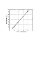
図4に、一実験例におけるヘッダ圧力Pとガスの衝突圧変動量σとの関係を示す。図4から明らかなように、ヘッダ圧力Pとガスの衝突圧変動量σとの間には正の線形相関があることがわかった。ヘッダ圧力Pを増加させれば、衝突圧そのものも増加することは自明である。しかしながら、本発明者らは、図4に示すように、衝突圧変動量σも、ヘッダ圧力が増加するほど大きくなることを初めて見出したのである。そして、この実験例では、衝突圧変動量σが300Pa以上の範囲で湯ジワの発生を確認した。 FIG. 4 shows the relationship between the header pressure P and the gas collision pressure fluctuation amount σ in one experimental example. As is clear from FIG. 4, it has been found that there is a positive linear correlation between the header pressure P and the gas collision pressure fluctuation amount σ. It is obvious that if the header pressure P is increased, the collision pressure itself is also increased. However, the present inventors have found for the first time that the collision pressure fluctuation amount σ also increases as the header pressure increases, as shown in FIG. In this experimental example, occurrence of hot water wrinkles was confirmed in the range where the collision pressure fluctuation amount σ was 300 Pa or more.
衝突圧変動量σが大きい場合、衝突圧の変動がめっきの初期凹凸を発生させ、湯ジワ欠陥となってしまうと考えられる。従って、湯ジワ抑制には衝突圧変動量σの低減が有効である。そして、図4に示す知見によれば、ヘッダ圧力を制御することによってガスの衝突圧変動量を制御できることがわかる。衝突圧変動量σを制御することによって、目標のめっき付着量を高精度に実現しやすくなり、湯ジワの発生を十分に抑え、高品質の溶融金属めっき鋼帯を低コストで製造できる。 When the collision pressure fluctuation amount σ is large, it is considered that the fluctuation of the collision pressure generates initial unevenness of the plating and causes a wrinkle defect. Therefore, reduction of the collision pressure fluctuation amount σ is effective for suppressing hot water wrinkles. Then, according to the knowledge shown in FIG. 4, it can be understood that the collision pressure fluctuation amount of the gas can be controlled by controlling the header pressure. By controlling the impact pressure fluctuation amount σ, it becomes easy to achieve the target plating adhesion amount with high accuracy, the occurrence of hot water wrinkles can be sufficiently suppressed, and a high-quality hot-dip coated steel strip can be manufactured at low cost.
ただし、ヘッダ圧力Pと衝突圧変動量σとの関係は、正の線形相関があることは変わらないものの、具体的な値の関係については、ノズルの形状、ノズルのスリットギャップB、及びノズル角度θによって異なる。また、湯ジワが発生し始める衝突圧変動量の閾値は、鋼帯の走行速度L及び目標のめっき厚さWによって異なることがわかった。 However, although the relationship between the header pressure P and the collision pressure fluctuation amount σ still has a positive linear correlation, the specific value relationship is determined by the nozzle shape, the nozzle slit gap B, and the nozzle angle. Depends on θ. Further, it was found that the threshold value of the collision pressure fluctuation amount at which the occurrence of hot water wrinkles differs depending on the running speed L of the steel strip and the target plating thickness W.
そこで、本発明者らがさらに検討を進めたところ、ガスの衝突圧変動量σを、鋼帯の走行速度L及び目標のめっき厚さWに応じて、以下の式(1)を満足するように制御することにより、湯ジワの発生を十分に抑え、高品質の溶融金属めっき鋼帯を製造できることがわかった。
L:鋼帯の走行速度[m/min]
W:目標のめっき厚さ[μm]
α,β:定数
Therefore, the present inventors have further studied and found that the gas collision pressure fluctuation amount σ satisfies the following expression (1) according to the traveling speed L of the steel strip and the target plating thickness W. It was found that by controlling the temperature, the generation of hot water wrinkles was sufficiently suppressed, and a high-quality hot-dip coated steel strip could be produced.
L: Running speed of steel strip [m / min]
W: Target plating thickness [μm]
α, β: constant
以下、式(1)を利用した操業条件の決定方法の一例について述べる。
(A)ノズルの形状、ノズルのスリットギャップB、及びノズル角度θが確定した使用めっき設備において、図4に示すような、ヘッダ圧力Pと衝突圧変動量σとの関係を予め求める。
(B)次に、目標のめっき厚さWを設定する。
(C)次に、鋼帯の厚さ及び幅に応じて、適正な鋼帯の走行速度Lを適宜決定する。
(D)次に、設定された目標のめっき厚さW及び鋼帯の走行速度Lを式(1)に代入して、ガスの衝突圧変動量σの好適範囲を決定する。
(E)次に、予め求めていたヘッダ圧力Pと衝突圧変動量σとの関係に基づいて、式(1)を満たすヘッダ圧力Pを決定する。
(F)次に、決定した鋼帯の走行速度L及びヘッダ圧力Pを考慮して、目標のめっき厚さWを得るための、ノズル先端−鋼帯間の距離D(図2参照)を決定する。
Hereinafter, an example of a method for determining operating conditions using Expression (1) will be described.
(A) In the plating equipment used in which the nozzle shape, the nozzle slit gap B, and the nozzle angle θ are determined, the relationship between the header pressure P and the collision pressure fluctuation amount σ as shown in FIG. 4 is obtained in advance.
(B) Next, a target plating thickness W is set.
(C) Next, an appropriate traveling speed L of the steel strip is appropriately determined according to the thickness and the width of the steel strip.
(D) Next, the set target plating thickness W and running speed L of the steel strip are substituted into the equation (1) to determine a suitable range of the gas collision pressure fluctuation amount σ.
(E) Next, the header pressure P that satisfies the expression (1) is determined based on the relationship between the header pressure P and the collision pressure fluctuation amount σ obtained in advance.
(F) Next, in consideration of the determined traveling speed L and header pressure P of the steel strip, a distance D (see FIG. 2) between the nozzle tip and the steel strip for obtaining the target plating thickness W is determined. I do.
なお、一般的な操業条件では、距離Dは3〜40mm程度とするが、この範囲内においては、距離Dの値に関わらず、ヘッダ圧力Pと衝突圧変動量σとの関係は変わらないことを、本発明者らは確認した。よって、上記(A)〜(F)の手順によって、湯ジワの発生を十分に抑えた操業が可能である。 Under general operating conditions, the distance D is about 3 to 40 mm. However, within this range, the relationship between the header pressure P and the collision pressure fluctuation amount σ does not change regardless of the value of the distance D. Have been confirmed by the present inventors. Therefore, by the above-described procedures (A) to (F), it is possible to perform an operation in which generation of hot water wrinkles is sufficiently suppressed.
ここで、式(1)における定数α,βは、ノズルの形状、ノズルのスリットギャップB、及びノズル角度θによって異なるため、オンライン実験で事前に決定する。以下、これら定数の求め方と、式(1)の技術的な意味について説明する。 Here, since the constants α and β in the equation (1) differ depending on the shape of the nozzle, the slit gap B of the nozzle, and the nozzle angle θ, they are determined in advance in an online experiment. Hereinafter, how to determine these constants and the technical meaning of equation (1) will be described.
ここで、式(1)の右辺は、湯ジワが発生しない衝突圧変動量σの上限値を示している。式(1)の右辺における各パラメータの意味について述べる。目標のめっき厚さWが増加すると、湯ジワが発生しやすくなるため、衝突圧変動量σの上限値が減少する。鋼帯走行速度Lが増加すると、ワイピングガスが衝突する時間が短くなり、湯ジワが発生しづらくなるため、衝突圧変動量σの上限値が上昇する。 Here, the right side of Expression (1) indicates the upper limit of the collision pressure fluctuation amount σ at which hot water wrinkles do not occur. The meaning of each parameter on the right side of Expression (1) will be described. When the target plating thickness W increases, hot water wrinkles easily occur, and the upper limit value of the collision pressure fluctuation amount σ decreases. When the steel strip traveling speed L increases, the time during which the wiping gas collides becomes shorter, and it becomes difficult to generate hot water wrinkles, so that the upper limit of the collision pressure fluctuation amount σ increases.
ここで、定数α,βは以下のように求める。既述の(B),(C)の方法で決定した目標のめっき厚さW及び鋼帯の走行速度Lの値の組み合わせ(W1、L1)において、ヘッダ圧力Pを種々変更して、湯ジワが発生し始める境界の衝突圧変動量σ1を求める。なお、めっき厚は、ヘッダ圧Pと、距離Dと、鋼帯の走行速度Lに依存する。よって、走行速度L1の操業下において、ヘッダ圧Pを種々変更するのに合わせて、目標めっき厚さW1を実現できるように、距離Dも適宜変更する必要がある。 Here, the constants α and β are obtained as follows. In the combination (W 1 , L 1 ) of the target plating thickness W and the value of the running speed L of the steel strip determined by the methods (B) and (C) described above, the header pressure P is variously changed. The collision pressure fluctuation amount σ 1 at the boundary where the hot water wrinkles begin to be generated is determined. The plating thickness depends on the header pressure P, the distance D, and the running speed L of the steel strip. Therefore, in the operation of a running speed L 1, the combined header pressure P to variously changed, so that it can realize the target plating thickness W 1, the distance D must be changed as appropriate.
さらに、既述の(B),(C)の方法で決定した別のW及びLの値の組合せ(W2、L2)において、ヘッダ圧力Pを種々変更して、湯ジワが発生し始める境界の衝突圧変動量σ2を求める。同様に、W及びLの値の複数の組合せ(Wk、Lk)(k;1〜nの整数)において、湯ジワが発生し始める境界の衝突圧変動量σkを求める。横軸をL/W2として、縦軸をσとしたグラフに、求めたn点をプロットする。n点のプロットから、最小二乗法で残差平方和が最小となる直線を求め、傾きの値をαとし、縦軸の切片をβとする。なお、「湯ジワが発生し始める境界の衝突圧変動量」とは、ワイピング後の鋼帯表面において、JIS B0601-2001の規格に基づいて測定した算術平均うねりWaが1.00μmとなる衝突圧変動量を意味するものとする。Waが1.00μmを超えると、目視で小さな湯ジワが確認できるからである。定数α,βの精度の観点から、nは4以上であることが好ましい。
Furthermore, in another combination (W 2 , L 2 ) of the values of W and L determined by the methods (B) and (C) described above, the header pressure P is variously changed, and hot water wrinkles begin to occur. The collision pressure fluctuation amount σ 2 at the boundary is obtained. Similarly, in a plurality of combinations of the values of W and L (W k , L k ) (k; an integer of 1 to n), the collision pressure fluctuation amount σ k at the boundary where the hot water wrinkle starts to be generated is obtained . The obtained n points are plotted on a graph in which the horizontal axis is L / W 2 and the vertical axis is σ. From the plot of n points, a straight line that minimizes the residual sum of squares is obtained by the least squares method, the value of the slope is α, and the intercept of the vertical axis is β. Note that the "impact pressure variation boundaries Yu wrinkles begin to occur" in the steel strip surface after wiping, the arithmetic mean waviness Wa is 1.00μm impact pressure variations measured based on the standard of JIS B0601-2001 Shall mean quantity . This is because if Wa exceeds 1.00 μm, small hot water wrinkles can be visually confirmed. From the viewpoint of the accuracy of the constants α and β, n is preferably 4 or more.
このように、湯ジワ欠陥を抑制するためには、鋼帯の走行速度L及び目標のめっき厚さWに応じて、ガスの衝突圧変動量σを制御する必要がある。そして、具体的には、図4に示すようなガスワイピングノズルのヘッダ圧力Pとガスの衝突圧変動量σとの関係を予め求め、ガスの衝突圧変動量σが式(1)を満足するようにヘッダ圧力Pを設定することができる。 As described above, in order to suppress hot water wrinkle defects, it is necessary to control the gas collision pressure fluctuation amount σ according to the running speed L of the steel strip and the target plating thickness W. More specifically, the relationship between the header pressure P of the gas wiping nozzle and the gas collision pressure fluctuation amount σ as shown in FIG. 4 is obtained in advance, and the gas collision pressure fluctuation amount satisfies Expression (1). The header pressure P can be set as described above.
そして、使用するめっき設備条件(ノズルの形状、ノズルのスリットギャップB、及びノズル角度θ)ごとに、図4に示すようなガスワイピングノズルのヘッダ圧力Pとガスの衝突圧変動量σとの関係を予め求め、また、オンライン実験で定数α,βを事前に決定しておく。そして、操業条件としての鋼帯の走行速度L及び目標のめっき厚さWの少なくとも1つが変更になった場合には、それに伴って、衝突圧変動量σの好適範囲、及びそれに対応するヘッダ圧力Pの好適範囲を変更する。 Then, the relationship between the header pressure P of the gas wiping nozzle and the gas collision pressure fluctuation amount σ as shown in FIG. 4 for each plating equipment condition (nozzle shape, nozzle slit gap B, and nozzle angle θ) used. Are determined in advance, and the constants α and β are determined in advance in an online experiment. When at least one of the running speed L of the steel strip and the target plating thickness W as operating conditions is changed, a suitable range of the collision pressure fluctuation amount σ and a corresponding header pressure are changed. Change the preferred range of P.
なお、図4に示す知見に従えば、湯ジワの発生を防ぐだけであれば、衝突圧変動量σ、すなわちヘッダ圧力Pを極力小さく設定すればよく、殊更に式(1)で湯ジワが発生しない衝突圧変動量σの上限値を把握する必要もない。しかしながら、衝突圧変動量σを低下させるためにヘッダ圧力Pを小さくすると、目標めっき厚さWを実現するために、距離Dを小さくせざるを得なくなる。すると、鋼帯の反りが発生した場合に、ノズルが鋼帯に接触したり、スプラッシュがノズルに付着しやすくなったりして、めっき表面に傷や欠陥が発生することが懸念される。また、ヘッダ圧力Pを小さくすると、特に鋼帯エッジ部の衝突圧力が弱まり、エッジ部の付着量が厚くなりすぎるため、鋼帯幅方向で不均一な付着量となってしまう可能性がある。この現状を本明細書ではエッジオーバーコートと呼ぶ。このような観点から、ヘッダ圧力Pは、衝突圧変動量σが式(1)を満たす範囲で極力大きく設定することが好ましい。そのため、本発明では、式(1)で湯ジワが発生しない衝突圧変動量σの上限値を把握することに意義がある。 According to the knowledge shown in FIG. 4, if only the occurrence of hot water wrinkles is to be prevented, the collision pressure fluctuation amount σ, that is, the header pressure P may be set as small as possible. It is not necessary to know the upper limit of the collision pressure fluctuation amount σ that does not occur. However, if the header pressure P is reduced to reduce the collision pressure fluctuation amount σ, the distance D must be reduced in order to achieve the target plating thickness W. Then, when the steel strip is warped, there is a concern that the nozzle may come into contact with the steel strip, splash may easily adhere to the nozzle, and scratches or defects may occur on the plating surface. In addition, when the header pressure P is reduced, the collision pressure particularly at the edge portion of the steel strip is weakened, and the adhesion amount at the edge portion becomes too thick, so that the adhesion amount may be uneven in the steel strip width direction. This situation is referred to herein as an edge overcoat. From such a viewpoint, it is preferable that the header pressure P is set as large as possible as long as the collision pressure fluctuation amount satisfies the expression (1). Therefore, in the present invention, it is significant to know the upper limit value of the collision pressure fluctuation amount σ at which the hot water wrinkle does not occur in Expression (1).
また、エッジオーバーコートを防ぐ有効な手段としては、ノズルの浴面からの高さの低下やバッフルプレートの使用が挙げられる。これらの手段の両方又は一方を実施することで、湯ジワやエッジオーバーコートの無いより美麗な外観を得ることが可能になる。 Effective means for preventing edge overcoat include lowering the height of the nozzle from the bath surface and using a baffle plate. By implementing both or one of these means, it becomes possible to obtain a more beautiful appearance without hot water wrinkles or edge overcoats.
ノズル高さを低下させると、鋼帯エッジ部のめっき表層が凝固する前にワイピングできるため、エッジオーバーコートを防止可能である。この観点から、ガスワイピングノズルの先端の高さを、溶融金属浴の表面から250mm以下とすることが好ましい。しかし、ワイピングノズル高さは低くしすぎると、浴面上でスプラッシュが多量に発生するため、100mm以上の高さが望ましい。 If the height of the nozzle is reduced, wiping can be performed before the plating surface layer of the steel strip edge portion solidifies, so that edge overcoat can be prevented. From this viewpoint, it is preferable that the height of the tip of the gas wiping nozzle be 250 mm or less from the surface of the molten metal bath. However, if the height of the wiping nozzle is too low, a large amount of splash occurs on the bath surface, so that a height of 100 mm or more is desirable.
また、図3を参照して、バッフルプレート28は、鋼帯Sの幅方向端部近傍の鋼帯延長面上に配置されるプレートを指す。バッフルプレートを設置することで、一対のガスワイピングノズルから噴射されたガス同士の衝突を回避できるため、エッジオーバーコートの防止が可能である。図3では、鋼帯Sの幅方向片側端部近傍に配置されたバッフルプレート28を図示したが、鋼帯幅方向の両側の端部近傍に、それぞれバッフルプレートを配置することが好ましい。バッフルプレート28と鋼帯Sの幅方向端部との最短距離dは、1〜10mm程度とすることが好ましい。
Referring to FIG. 3,
ノズル20A,20Bから噴射されるガスは、不活性ガスであることが好ましい。不活性ガスにすることで、鋼帯表面上の溶融金属の酸化を防止できるため、溶融金属の粘度ムラをさらに抑制することができる。不活性ガスとしては、窒素、アルゴン、ヘリウム、二酸化炭素等が挙げられるが、これらに限定されるものではない。
The gas injected from the
本実施形態において、溶融金属の成分は、Al:1.0〜10質量%、Mg:0.2〜1質量%、Ni:0〜0.1質量%を含有し、残部がZn及び不可避的不純物からなることが好ましい。このようにMgが含まれると、溶融金属の酸化/冷却による粘度ムラが生じやすく、湯ジワが発生しやすくなることが確認されている。また、上記の成分系では、Zn100%の溶融金属と比較すると粘度が低いため、淀み点で初期凹凸が発生した際に、溶融金属が固まる前により初期凹凸が大きく成長するため、湯ジワが発生しやすくなる。そのため、溶融金属が上記成分組成を有する場合に、本発明の湯ジワを抑制する効果が顕著に表れる。また、溶融金属の組成が、5質量%Al−Znの場合や、55質量%Al−Znの場合にも、本発明の湯ジワを抑制する効果を得ることができる。 In this embodiment, the components of the molten metal include Al: 1.0 to 10% by mass, Mg: 0.2 to 1% by mass, and Ni: 0 to 0.1% by mass, and the balance is preferably composed of Zn and inevitable impurities. . It has been confirmed that when Mg is contained as described above, unevenness in viscosity due to oxidation / cooling of the molten metal is likely to occur, and hot water wrinkles are likely to occur. In addition, in the above-mentioned component system, since the viscosity is lower than that of molten metal of 100% Zn, when initial unevenness occurs at the stagnation point, the initial unevenness grows larger before the molten metal solidifies, so that hot water wrinkles are generated. Easier to do. Therefore, when the molten metal has the above component composition, the effect of suppressing the hot water wrinkles of the present invention is remarkably exhibited. Further, even when the composition of the molten metal is 5% by mass Al—Zn or 55% by mass Al—Zn, the effect of suppressing hot water wrinkles of the present invention can be obtained.
本発明の製造方法で製造される溶融金属めっき鋼帯としては、溶融亜鉛めっき鋼板を挙げることができ、これは、溶融亜鉛めっき処理後合金化処理を施さないめっき鋼板(GI)と、合金化処理を施すめっき鋼板(GA)のいずれも含む。 Examples of the hot-dip galvanized steel strip manufactured by the manufacturing method of the present invention include a hot-dip galvanized steel sheet. Includes any coated steel sheet (GA) to be treated.
溶融亜鉛めっき鋼帯の製造ラインにおいて、溶融亜鉛めっき鋼帯の製造試験を行った。各発明例及び比較例で、図1に示すめっき設備を用いた。ガスワイピングノズルは、ノズルギャップBが1.2mmのものを使用した。各発明例及び比較例で、めっき浴の組成、めっき浴の温度T、めっき浴の融点TM、目標のめっき厚さW、鋼帯の走行速度L、ワイピングノズルのヘッダガス圧力P、ワイピングガスの衝突圧変動量σ、ノズル先端と鋼帯との距離D、ノズル角度θ、ノズル高さH、バッフルプレートの使用有無は、表1に示すものとした。ノズル先端と鋼帯との距離Dは、鋼帯片面中央部のめっき付着量がWを満たすよう、鋼帯走行速度Lやヘッダ圧力Pの値を考慮して設定した。 A production test of a hot-dip galvanized steel strip was performed on a hot-dip galvanized steel strip manufacturing line. In each of the invention examples and the comparative examples, the plating equipment shown in FIG. 1 was used. The gas wiping nozzle used had a nozzle gap B of 1.2 mm. In each of the invention examples and comparative examples, the composition of the plating bath, the temperature T of the plating bath, the melting point T M of the plating bath, the target plating thickness W, the traveling speed L of the steel strip, the header gas pressure P of the wiping nozzle, and the Table 1 shows the impact pressure fluctuation amount σ, the distance D between the nozzle tip and the steel strip, the nozzle angle θ, the nozzle height H, and the use of the baffle plate. The distance D between the nozzle tip and the steel strip was set in consideration of the values of the steel strip running speed L and the header pressure P such that the plating adhesion amount at the center of one side of the steel strip satisfies W.
ガスワイピングノズルへのガス供給方法として、コンプレッサーで所定圧力に加圧したものを供給する方法を採用した。こうして、板厚1.2mm×板幅1000mmの鋼帯を通板して、溶融亜鉛めっき鋼帯を製造した。 As a method of supplying gas to the gas wiping nozzle, a method of supplying a gas pressurized to a predetermined pressure by a compressor was employed. In this way, a steel strip having a thickness of 1.2 mm and a width of 1000 mm was passed through to produce a hot-dip galvanized steel strip.
なお、事前のオンラインテストで式(1)中の定数をそれぞれ求めたところ、α=1725,β=-60であった。式(1)から算出される衝突圧変動量σの好適範囲も表1に示す。 In addition, when the constants in the equation (1) were obtained by a preliminary online test, they were α = 1725 and β = -60. Table 1 also shows a preferred range of the collision pressure fluctuation amount σ calculated from the equation (1).
また、製造された溶融亜鉛めっき鋼帯の外観と、両面の合計めっき付着量を評価した。鋼板の外観評価については、以下の基準で合否を判定した。結果を表1に示す。
×:不合格=目視で大きな湯ジワが確認できる亜鉛めっき鋼板(1.50<Wa)
△:不合格=目視で小さな湯ジワが確認できる亜鉛めっき鋼板(1.00<Wa≦1.50)
○:合格=目視で湯ジワが確認できない美麗な亜鉛めっき鋼板(0.50<Wa≦1.00)
◎:合格=目視で湯ジワが確認できない非常に美麗な亜鉛めっき鋼板(0<Wa≦0.50)
なお、Waは、JIS B0601-2001の規格に基づいて測定した算術平均うねりWa[μm]の値である。
In addition, the appearance of the manufactured hot-dip galvanized steel strip and the total coating weight of both sides were evaluated. Regarding the appearance evaluation of the steel sheet, pass / fail was determined based on the following criteria. Table 1 shows the results.
×: rejected = galvanized steel sheet (1.50 <Wa) where large hot water wrinkles can be visually confirmed
△: rejected = galvanized steel sheet (1.00 <Wa ≦ 1.50) where small wrinkles can be visually observed
:: Pass = beautiful galvanized steel sheet with no visible wrinkles (0.50 <Wa ≦ 1.00)
◎: Pass = Very beautiful galvanized steel sheet with no visible wrinkles (0 <Wa ≦ 0.50)
In addition, Wa is a value of the arithmetic mean waviness Wa [μm] measured based on the standard of JIS B0601-2001.
また、表1中のCは、C=(鋼帯端部の付着量−鋼帯中央部の付着量)/鋼帯中央部の付着量×100で示される、鋼帯中央と鋼帯端部のめっき付着量偏差[%]の値である。 C in Table 1 is C = (the amount of adhesion at the end of the steel strip−the amount of adhesion at the center of the steel strip) / the amount of adhesion at the center of the steel strip × 100. Is the value of the plating adhesion amount deviation [%].
表1から明らかなように、衝突圧変動量σが式(1)を満たしている場合、Waが低く美麗な表面外観が得られるのに対して、衝突圧変動量σが式(1)を満たしていない場合、Waが大きくなってしまった。特に、めっき種B,Eでは、衝突圧変動量σを本発明範囲とした場合の効果が顕著に得られた。 As is clear from Table 1, when the impact pressure fluctuation amount satisfies the expression (1), a beautiful surface appearance with a low Wa is obtained, whereas the collision pressure fluctuation amount σ is the expression (1). If not, Wa has increased. In particular, in the plating types B and E, the effect when the impact pressure fluctuation amount σ was within the range of the present invention was remarkably obtained.
また、ノズル高さHが250mm以下を満たしている場合やバッフルプレートを使用した場合は、幅方向の付着量偏差Cが低下しており、エッジオーバーコートを防止する効果を得られた。 Further, when the nozzle height H was less than 250 mm or when a baffle plate was used, the adhesion amount deviation C in the width direction was reduced, and an effect of preventing edge overcoat was obtained.
本発明の溶融金属めっき鋼帯の製造方法によれば、湯ジワの発生を十分に抑え、高品質の溶融金属めっき鋼帯を低コストで製造できる。 ADVANTAGE OF THE INVENTION According to the manufacturing method of the hot-dip metal-plated steel strip of this invention, generation | occurrence | production of hot water wrinkles is fully suppressed, and a high-quality hot-dip metal-plated steel strip can be manufactured at low cost.
100 連続溶融金属めっき設備
10 スナウト
12 めっき槽
14 溶融金属浴
16 シンクロール
18 サポートロール
20A,20B ガスワイピングノズル
22 ノズルヘッダ
24A 上ノズル部材
24B 下ノズル部材
26 噴射口(ノズルスリット)
28 バッフルプレート
S 鋼帯
B スリットギャップ
D ガスワイピングノズルの先端と鋼帯との距離
θ ノズル角度
REFERENCE SIGNS
28 Baffle plate S Steel strip B Slit gap D Distance between tip of gas wiping nozzle and steel strip θ Nozzle angle
Claims (4)
前記溶融金属浴から引き上げられる鋼帯に、該鋼帯を挟んで配置される一対のガスワイピングノズルからガスを吹き付けて、該鋼帯の両面の溶融金属の付着量を調整して、
連続的に溶融金属めっき鋼帯を製造する溶融金属めっき鋼帯の製造方法であって、
前記ガスワイピングノズルのヘッダ圧力P[kPa]と、前記ガスの衝突圧変動量σとの関係を予め求め、
当該関係に基づいて、前記ガスの衝突圧変動量σが、前記鋼帯の走行速度L及び目標のめっき厚さWに応じて、以下の式(1)を満足するように前記ヘッダ圧力Pを決定し、
目標のめっき厚さWを得るためのノズル先端−鋼帯間の距離Dを決定し、
決定された前記ヘッダ圧力P及び前記距離Dの条件下で、前記ガスの吹き付けを行うことを特徴とする、溶融金属めっき鋼帯の製造方法。
L:鋼帯の走行速度[m/min]
W:目標のめっき厚さ[μm]
α,β:定数 Continuously immerse steel strip in molten metal bath,
A gas is blown from a pair of gas wiping nozzles arranged on the steel strip pulled up from the molten metal bath, with the steel strip interposed therebetween to adjust the amount of adhered molten metal on both surfaces of the steel strip,
A method for manufacturing a hot-dip metal-plated steel strip for continuously manufacturing a hot-dip metal-plated steel strip,
A relationship between a header pressure P [kPa] of the gas wiping nozzle and a collision pressure fluctuation amount σ of the gas is obtained in advance,
Based on the relationship, impact pressure variation of the gas σ is in accordance with the running speed L and the target of the plating thickness W of the steel strip, the header pressure P so as to satisfy the following equation (1) Decide,
Determine the distance D between the nozzle tip and the steel strip to obtain the target plating thickness W,
The method of manufacturing a hot-dip metal-plated steel strip , wherein the blowing of the gas is performed under the determined conditions of the header pressure P and the distance D.
L: Running speed of steel strip [m / min]
W: Target plating thickness [μm]
α, β: constant
Priority Applications (1)
| Application Number | Priority Date | Filing Date | Title |
|---|---|---|---|
| JP2017075451A JP6635086B2 (en) | 2017-04-05 | 2017-04-05 | Manufacturing method of hot-dip galvanized steel strip |
Applications Claiming Priority (1)
| Application Number | Priority Date | Filing Date | Title |
|---|---|---|---|
| JP2017075451A JP6635086B2 (en) | 2017-04-05 | 2017-04-05 | Manufacturing method of hot-dip galvanized steel strip |
Publications (2)
| Publication Number | Publication Date |
|---|---|
| JP2018178158A JP2018178158A (en) | 2018-11-15 |
| JP6635086B2 true JP6635086B2 (en) | 2020-01-22 |
Family
ID=64282366
Family Applications (1)
| Application Number | Title | Priority Date | Filing Date |
|---|---|---|---|
| JP2017075451A Active JP6635086B2 (en) | 2017-04-05 | 2017-04-05 | Manufacturing method of hot-dip galvanized steel strip |
Country Status (1)
| Country | Link |
|---|---|
| JP (1) | JP6635086B2 (en) |
Family Cites Families (4)
| Publication number | Priority date | Publication date | Assignee | Title |
|---|---|---|---|---|
| JP3011395B2 (en) * | 1995-07-31 | 2000-02-21 | 川崎製鉄株式会社 | Method for producing thick galvanized steel sheet with excellent surface properties |
| JP3278607B2 (en) * | 1998-02-20 | 2002-04-30 | 川崎製鉄株式会社 | Method for producing hot-dip galvanized steel sheet with good surface properties |
| JP2002241918A (en) * | 2001-02-15 | 2002-08-28 | Nippon Steel Corp | Manufacturing method of hot-dip coated steel sheet and its manufacturing equipment |
| JP6011740B2 (en) * | 2014-10-08 | 2016-10-19 | Jfeスチール株式会社 | Continuous molten metal plating method, hot dip galvanized steel strip, and continuous molten metal plating facility |
-
2017
- 2017-04-05 JP JP2017075451A patent/JP6635086B2/en active Active
Also Published As
| Publication number | Publication date |
|---|---|
| JP2018178158A (en) | 2018-11-15 |
Similar Documents
| Publication | Publication Date | Title |
|---|---|---|
| KR101910756B1 (en) | Continuous hot-dip metal coating method, galvanized steel strip, and continuous hot-dip metal coating facility | |
| AU2020204123B2 (en) | Method for manufacturing molten metal plated steel strip and continuous molten metal plating equipment | |
| CN114502764B (en) | Apparatus and method for manufacturing plated metal strips with improved appearance | |
| KR102471806B1 (en) | Manufacturing method of hot-dip metal plating steel strip and continuous hot-dip metal plating equipment | |
| JP6500846B2 (en) | Method of manufacturing hot-dip metallized steel strip and continuous hot-dip metal plating equipment | |
| JP4857906B2 (en) | Manufacturing method of molten metal plated steel strip | |
| JP6635086B2 (en) | Manufacturing method of hot-dip galvanized steel strip | |
| JP6638872B1 (en) | Method for producing hot-dip coated steel strip and continuous hot-dip metal plating equipment | |
| JP6414360B2 (en) | Manufacturing method of molten metal plated steel strip | |
| JP6394578B2 (en) | Manufacturing method of molten metal plating steel strip and continuous molten metal plating equipment | |
| JP5386779B2 (en) | Method and apparatus for manufacturing hot-dip galvanized steel sheet | |
| JP6772930B2 (en) | Manufacturing method of hot-dip galvanized steel sheet and hot-dip galvanized steel sheet | |
| JP6870659B2 (en) | Gas wiping nozzle for hot metal plating equipment, gas wiping method for hot metal plating, and manufacturing method for hot metal plated steel sheet |
Legal Events
| Date | Code | Title | Description |
|---|---|---|---|
| A621 | Written request for application examination |
Free format text: JAPANESE INTERMEDIATE CODE: A621 Effective date: 20181122 |
|
| A977 | Report on retrieval |
Free format text: JAPANESE INTERMEDIATE CODE: A971007 Effective date: 20190813 |
|
| A131 | Notification of reasons for refusal |
Free format text: JAPANESE INTERMEDIATE CODE: A131 Effective date: 20190827 |
|
| A521 | Request for written amendment filed |
Free format text: JAPANESE INTERMEDIATE CODE: A523 Effective date: 20191010 |
|
| TRDD | Decision of grant or rejection written | ||
| A01 | Written decision to grant a patent or to grant a registration (utility model) |
Free format text: JAPANESE INTERMEDIATE CODE: A01 Effective date: 20191119 |
|
| A61 | First payment of annual fees (during grant procedure) |
Free format text: JAPANESE INTERMEDIATE CODE: A61 Effective date: 20191202 |
|
| R150 | Certificate of patent or registration of utility model |
Ref document number: 6635086 Country of ref document: JP Free format text: JAPANESE INTERMEDIATE CODE: R150 |
|
| R250 | Receipt of annual fees |
Free format text: JAPANESE INTERMEDIATE CODE: R250 |
|
| R250 | Receipt of annual fees |
Free format text: JAPANESE INTERMEDIATE CODE: R250 |
|
| R250 | Receipt of annual fees |
Free format text: JAPANESE INTERMEDIATE CODE: R250 |