JP6213776B2 - スイッチング基板 - Google Patents
スイッチング基板 Download PDFInfo
- Publication number
- JP6213776B2 JP6213776B2 JP2014009720A JP2014009720A JP6213776B2 JP 6213776 B2 JP6213776 B2 JP 6213776B2 JP 2014009720 A JP2014009720 A JP 2014009720A JP 2014009720 A JP2014009720 A JP 2014009720A JP 6213776 B2 JP6213776 B2 JP 6213776B2
- Authority
- JP
- Japan
- Prior art keywords
- bus bar
- control circuit
- semiconductor switching
- input bus
- terminal
- Prior art date
- Legal status (The legal status is an assumption and is not a legal conclusion. Google has not performed a legal analysis and makes no representation as to the accuracy of the status listed.)
- Active
Links
- 239000004065 semiconductor Substances 0.000 claims description 40
- 238000003780 insertion Methods 0.000 claims description 10
- 230000037431 insertion Effects 0.000 claims description 10
- 230000003014 reinforcing effect Effects 0.000 claims description 10
- 230000000149 penetrating effect Effects 0.000 claims description 5
- 239000011810 insulating material Substances 0.000 claims 1
- 239000000758 substrate Substances 0.000 description 18
- 230000003071 parasitic effect Effects 0.000 description 7
- 230000002787 reinforcement Effects 0.000 description 6
- 230000004048 modification Effects 0.000 description 5
- 238000012986 modification Methods 0.000 description 5
- 239000004020 conductor Substances 0.000 description 4
- RYGMFSIKBFXOCR-UHFFFAOYSA-N Copper Chemical compound [Cu] RYGMFSIKBFXOCR-UHFFFAOYSA-N 0.000 description 3
- 229910000881 Cu alloy Inorganic materials 0.000 description 3
- 229910052802 copper Inorganic materials 0.000 description 3
- 239000010949 copper Substances 0.000 description 3
- 230000017525 heat dissipation Effects 0.000 description 3
- 239000000463 material Substances 0.000 description 3
- 230000002457 bidirectional effect Effects 0.000 description 2
- 239000000446 fuel Substances 0.000 description 2
- 239000011521 glass Substances 0.000 description 2
- 238000000034 method Methods 0.000 description 2
- 229910000679 solder Inorganic materials 0.000 description 2
- 239000003990 capacitor Substances 0.000 description 1
- 230000000694 effects Effects 0.000 description 1
- 230000005669 field effect Effects 0.000 description 1
- 239000002184 metal Substances 0.000 description 1
- 229910052751 metal Inorganic materials 0.000 description 1
- 239000000203 mixture Substances 0.000 description 1
- 239000004745 nonwoven fabric Substances 0.000 description 1
- 230000001172 regenerating effect Effects 0.000 description 1
- 238000005476 soldering Methods 0.000 description 1
- 239000007858 starting material Substances 0.000 description 1
- 229920003002 synthetic resin Polymers 0.000 description 1
- 239000000057 synthetic resin Substances 0.000 description 1
Images


Classifications
-
- H—ELECTRICITY
- H03—ELECTRONIC CIRCUITRY
- H03K—PULSE TECHNIQUE
- H03K17/00—Electronic switching or gating, i.e. not by contact-making and –breaking
- H03K17/06—Modifications for ensuring a fully conducting state
- H03K17/063—Modifications for ensuring a fully conducting state in field-effect transistor switches
-
- H—ELECTRICITY
- H05—ELECTRIC TECHNIQUES NOT OTHERWISE PROVIDED FOR
- H05K—PRINTED CIRCUITS; CASINGS OR CONSTRUCTIONAL DETAILS OF ELECTRIC APPARATUS; MANUFACTURE OF ASSEMBLAGES OF ELECTRICAL COMPONENTS
- H05K1/00—Printed circuits
- H05K1/18—Printed circuits structurally associated with non-printed electric components
-
- H—ELECTRICITY
- H05—ELECTRIC TECHNIQUES NOT OTHERWISE PROVIDED FOR
- H05K—PRINTED CIRCUITS; CASINGS OR CONSTRUCTIONAL DETAILS OF ELECTRIC APPARATUS; MANUFACTURE OF ASSEMBLAGES OF ELECTRICAL COMPONENTS
- H05K1/00—Printed circuits
- H05K1/02—Details
- H05K1/0201—Thermal arrangements, e.g. for cooling, heating or preventing overheating
- H05K1/0203—Cooling of mounted components
-
- H—ELECTRICITY
- H03—ELECTRONIC CIRCUITRY
- H03K—PULSE TECHNIQUE
- H03K17/00—Electronic switching or gating, i.e. not by contact-making and –breaking
- H03K17/51—Electronic switching or gating, i.e. not by contact-making and –breaking characterised by the components used
- H03K17/56—Electronic switching or gating, i.e. not by contact-making and –breaking characterised by the components used by the use, as active elements, of semiconductor devices
- H03K17/687—Electronic switching or gating, i.e. not by contact-making and –breaking characterised by the components used by the use, as active elements, of semiconductor devices the devices being field-effect transistors
- H03K17/6871—Electronic switching or gating, i.e. not by contact-making and –breaking characterised by the components used by the use, as active elements, of semiconductor devices the devices being field-effect transistors the output circuit comprising more than one controlled field-effect transistor
-
- H—ELECTRICITY
- H03—ELECTRONIC CIRCUITRY
- H03K—PULSE TECHNIQUE
- H03K17/00—Electronic switching or gating, i.e. not by contact-making and –breaking
- H03K17/06—Modifications for ensuring a fully conducting state
- H03K2017/066—Maximizing the OFF-resistance instead of minimizing the ON-resistance
-
- H—ELECTRICITY
- H05—ELECTRIC TECHNIQUES NOT OTHERWISE PROVIDED FOR
- H05K—PRINTED CIRCUITS; CASINGS OR CONSTRUCTIONAL DETAILS OF ELECTRIC APPARATUS; MANUFACTURE OF ASSEMBLAGES OF ELECTRICAL COMPONENTS
- H05K2201/00—Indexing scheme relating to printed circuits covered by H05K1/00
- H05K2201/10—Details of components or other objects attached to or integrated in a printed circuit board
- H05K2201/10007—Types of components
- H05K2201/10166—Transistor
Landscapes
- Engineering & Computer Science (AREA)
- Microelectronics & Electronic Packaging (AREA)
- Structure Of Printed Boards (AREA)
- Inverter Devices (AREA)
- Power Conversion In General (AREA)
- Connection Or Junction Boxes (AREA)
- Charge And Discharge Circuits For Batteries Or The Like (AREA)
Description
本実施形態によれば、メインバッテリ90と補助バッテリ91との間に配されるスイッチング基板10に必要なバスバー30、40、50、制御回路基板20、および半導体スイッチング素子60A、60Bをシンプルにレイアウトすることができ、簡易な構成のスイッチング基板10を提供できる。また、接続バスバー50が接続部51と補強部52とを備えているから、シンプルな構成で、接続バスバー50に補強の役目を担わせることができる。この補強の効果により、例えばリフローはんだ実装工程で制御回路基板20に反りが発生することを抑制できる。
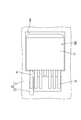
本発明の変形例を図11〜図13を参照しつつ説明する。本変形例のスイッチング装置100は、スイッチング基板101が放熱板102を備え、ケーシング103の上部ケース104が放熱板102を外部に露出させるための放熱窓105を備えている点を除き、実施形態と同様の構成である。スイッチング装置100において、実施形態と同様の構成については、同一の符号を付して説明を省略する。
本発明は上記記述及び図面によって説明した実施形態に限定されるものではなく、例えば次のような実施形態も本発明の技術的範囲に含まれる。
(1)上記実施形態では、接続バスバー50が接続部51と補強部52とを備えるT字形の板であったが、接続バスバーは必ずしもT字形でなくてもよく、例えば、補強部を有しないI字形の板であってもよい。また、接続部は必ずしも入力バスバーと出力バスバーとの間に配置されていなくても構わない。
11…回路構成体
20…制御回路基板
21…絶縁板
22…制御回路
24A…第1実装窓
24B…第2実装窓
30…入力バスバー
40…出力バスバー
50…接続バスバー
51…接続部
52…補強部
60A…第1半導体スイッチング素子
60B…第2半導体スイッチング素子
62…ドレイン端子
63…ソース端子
64…ゲート端子
90…メインバッテリ(主電源)
91…補助バッテリ(補助電源)
102…放熱板
Claims (2)
- 主電源と補助電源とを備える車両において、前記主電源と前記補助電源との間に、前記主電源および前記補助電源に対して直列に接続されるスイッチング基板であって、
絶縁性材料からなる絶縁板と、前記絶縁板の一面に配される制御回路と、前記絶縁板の前記制御回路が設けられた面からその逆側の面まで貫通する複数の実装窓とを備える制御回路基板と、ボルト挿通孔を有し、前記絶縁板の前記逆側の面に互いに間隔を空けて配置される入力バスバーおよび出力バスバーと、前記入力バスバーおよび前記出力バスバーに対して隙間を空けて配置される接続バスバーとを備える回路構成体と、
前記回路構成体に実装され、ドレイン端子、ソース端子およびゲート端子を備える複数の半導体スイッチング素子と、
前記入力バスバーおよび前記出力バスバーの前記ボルト挿通孔にそれぞれ挿通されるスタッドボルトと、前記スタッドボルトの先端に締め付けられるナットとを備え、
前記複数の実装窓のうち一部の実装窓は、内側に前記入力バスバーの一部と前記接続バスバーの一部とが露出する第1実装窓であり、他の実装窓は、内側に前記出力バスバーの一部と前記接続バスバーの一部とが露出する第2実装窓であり、
前記複数の半導体スイッチング素子のうち一部の半導体スイッチング素子は、前記第1実装窓の内側に配置され、前記ドレイン端子が前記入力バスバーの一部に接続され、前記ソース端子が前記接続バスバーの一部に接続され、前記ゲート端子が前記制御回路に接続される第1半導体スイッチング素子であり、他の半導体スイッチング素子は、前記第2実装窓の内側に配置され、前記ドレイン端子が前記出力バスバーの一部に接続され、前記ソース端子が前記接続バスバーの一部に接続され、前記ゲート端子が前記制御回路に接続される第2半導体スイッチング素子であり、
前記接続バスバーが、前記入力バスバーと前記出力バスバーとの間に配置される接続部と、前記入力バスバーおよび前記出力バスバーの並び方向に沿って延びる補強部とを備える、スイッチング基板。 - 前記回路構成体が、前記入力バスバー、前記出力バスバーおよび前記接続バスバーにおいて前記制御回路基板とは逆側の面に配置される放熱板を備える、請求項1に記載のスイッチング基板。
Priority Applications (5)
| Application Number | Priority Date | Filing Date | Title |
|---|---|---|---|
| JP2014009720A JP6213776B2 (ja) | 2014-01-22 | 2014-01-22 | スイッチング基板 |
| PCT/JP2015/050482 WO2015111450A1 (ja) | 2014-01-22 | 2015-01-09 | スイッチング基板 |
| EP15740599.4A EP3098951A4 (en) | 2014-01-22 | 2015-01-09 | Switching substrate |
| US15/113,576 US9930782B2 (en) | 2014-01-22 | 2015-01-09 | Switching board |
| CN201580004519.XA CN105917561B (zh) | 2014-01-22 | 2015-01-09 | 开关基板 |
Applications Claiming Priority (1)
| Application Number | Priority Date | Filing Date | Title |
|---|---|---|---|
| JP2014009720A JP6213776B2 (ja) | 2014-01-22 | 2014-01-22 | スイッチング基板 |
Publications (2)
| Publication Number | Publication Date |
|---|---|
| JP2015139286A JP2015139286A (ja) | 2015-07-30 |
| JP6213776B2 true JP6213776B2 (ja) | 2017-10-18 |
Family
ID=53681258
Family Applications (1)
| Application Number | Title | Priority Date | Filing Date |
|---|---|---|---|
| JP2014009720A Active JP6213776B2 (ja) | 2014-01-22 | 2014-01-22 | スイッチング基板 |
Country Status (5)
| Country | Link |
|---|---|
| US (1) | US9930782B2 (ja) |
| EP (1) | EP3098951A4 (ja) |
| JP (1) | JP6213776B2 (ja) |
| CN (1) | CN105917561B (ja) |
| WO (1) | WO2015111450A1 (ja) |
Families Citing this family (11)
| Publication number | Priority date | Publication date | Assignee | Title |
|---|---|---|---|---|
| JP6252872B2 (ja) * | 2015-02-24 | 2017-12-27 | 株式会社オートネットワーク技術研究所 | 電気接続箱及び接続端子部品 |
| EP3327825B1 (en) * | 2016-11-25 | 2019-10-02 | Samsung SDI Co., Ltd. | Busbar for a battery system |
| EP3327826A1 (en) * | 2016-11-29 | 2018-05-30 | Samsung SDI Co., Ltd. | A bus bar for the electrical connection of at least two terminals of a battery system and a corresponding battery system |
| JP6699535B2 (ja) * | 2016-12-14 | 2020-05-27 | 株式会社デンソー | 回路基板 |
| JP6705396B2 (ja) * | 2017-02-27 | 2020-06-03 | 株式会社オートネットワーク技術研究所 | 温度ヒューズ及び電気接続箱 |
| JP6988729B2 (ja) * | 2018-07-31 | 2022-01-05 | 株式会社オートネットワーク技術研究所 | 電気接続箱 |
| KR102554431B1 (ko) * | 2018-09-05 | 2023-07-13 | 삼성전자주식회사 | 반도체 장치 및 반도체 장치 제조 방법 |
| JP6926132B2 (ja) * | 2019-01-23 | 2021-08-25 | 矢崎総業株式会社 | 保護回路ユニット及び車両用電源装置 |
| JP7275619B2 (ja) * | 2019-02-08 | 2023-05-18 | 富士電機株式会社 | 電力変換装置 |
| JP7044744B2 (ja) * | 2019-08-23 | 2022-03-30 | 矢崎総業株式会社 | コネクタ |
| US12080634B2 (en) * | 2019-11-27 | 2024-09-03 | The Noco Company | Semiconductor device, printed circuit board (PCB), and method of interfacing control pin (gate pin) of a power semiconductor device (MOSFET) to a printed circuit board (PCB) |
Family Cites Families (15)
| Publication number | Priority date | Publication date | Assignee | Title |
|---|---|---|---|---|
| US5077778A (en) | 1990-08-27 | 1991-12-31 | Fabian Carl E | Film cassette having marker for identifying the exposure side of a medical radiograph |
| US6078501A (en) * | 1997-12-22 | 2000-06-20 | Omnirel Llc | Power semiconductor module |
| DE19813369B4 (de) * | 1998-03-26 | 2006-11-23 | Robert Bosch Gmbh | Vorrichtung zur Spannungsversorgung in einem Kraftfahrzeug |
| JP2003218554A (ja) * | 2001-11-14 | 2003-07-31 | Yazaki Corp | 電源分配箱及びパワーデバイスモジュール |
| JP3927017B2 (ja) * | 2001-11-26 | 2007-06-06 | 株式会社オートネットワーク技術研究所 | 回路構成体及びその製造方法 |
| DE10254910B4 (de) * | 2001-11-26 | 2008-12-24 | AutoNetworks Technologies, Ltd., Nagoya | Schaltkreisbildende Einheit und Verfahren zu deren Herstellung |
| JP2004063681A (ja) * | 2002-07-26 | 2004-02-26 | Hitachi Unisia Automotive Ltd | 半導体装置 |
| JP2006060949A (ja) * | 2004-08-23 | 2006-03-02 | Matsushita Electric Ind Co Ltd | 電源バックアップユニットおよびこれを用いた電子制御装置 |
| JP4073903B2 (ja) * | 2004-09-22 | 2008-04-09 | シャープ株式会社 | 半導体装置、フレキシブル基板、及び半導体装置を備えた電子機器 |
| US7242561B2 (en) * | 2005-01-12 | 2007-07-10 | Silicon Integrated System Corp. | ESD protection unit with ability to enhance trigger-on speed of low voltage triggered PNP |
| JP4720756B2 (ja) * | 2007-02-22 | 2011-07-13 | トヨタ自動車株式会社 | 半導体電力変換装置およびその製造方法 |
| JP4911009B2 (ja) | 2007-12-11 | 2012-04-04 | 株式会社デンソー | バスバーとバスバーを備えた半導体装置 |
| JP2009164039A (ja) | 2008-01-09 | 2009-07-23 | Fujikura Ltd | 2芯平行ケーブル |
| JP5370733B2 (ja) * | 2009-01-27 | 2013-12-18 | 株式会社オートネットワーク技術研究所 | 電気接続箱 |
| US10236664B2 (en) * | 2015-08-17 | 2019-03-19 | Siemens Industry, Inc. | Feed thru main breaker apparatus, systems and methods |
-
2014
- 2014-01-22 JP JP2014009720A patent/JP6213776B2/ja active Active
-
2015
- 2015-01-09 CN CN201580004519.XA patent/CN105917561B/zh active Active
- 2015-01-09 WO PCT/JP2015/050482 patent/WO2015111450A1/ja active Application Filing
- 2015-01-09 US US15/113,576 patent/US9930782B2/en active Active
- 2015-01-09 EP EP15740599.4A patent/EP3098951A4/en not_active Withdrawn
Also Published As
| Publication number | Publication date |
|---|---|
| EP3098951A4 (en) | 2017-01-11 |
| US20170006703A1 (en) | 2017-01-05 |
| EP3098951A1 (en) | 2016-11-30 |
| CN105917561B (zh) | 2018-11-09 |
| US9930782B2 (en) | 2018-03-27 |
| WO2015111450A1 (ja) | 2015-07-30 |
| JP2015139286A (ja) | 2015-07-30 |
| CN105917561A (zh) | 2016-08-31 |
Similar Documents
| Publication | Publication Date | Title |
|---|---|---|
| JP6213776B2 (ja) | スイッチング基板 | |
| US10141660B2 (en) | Electrical connection box and connection terminal component | |
| JP5995113B2 (ja) | 電気接続箱 | |
| JP4238797B2 (ja) | 電気接続箱 | |
| JP2014011926A (ja) | 電動車両用電力変換装置 | |
| WO2017047373A1 (ja) | 回路構成体および電気接続箱 | |
| JP6115779B2 (ja) | スイッチング基板 | |
| WO2016125543A1 (ja) | 回路構成体 | |
| KR102415020B1 (ko) | 전력반도체 탑재 구조물 | |
| JP5648627B2 (ja) | 電力変換装置 | |
| CN108738368B (zh) | 电子设备 | |
| US20210368618A1 (en) | Circuit assembly and electrical junction box | |
| JP7151232B2 (ja) | 回路基板 | |
| JP2009033902A (ja) | パワーモジュール | |
| WO2020017469A1 (ja) | 回路基板 | |
| JP6321883B2 (ja) | 電子部品ユニット及び熱伝導載置部材 | |
| JP6167965B2 (ja) | 回路ユニット | |
| CN112951818B (zh) | 功率转换装置 | |
| US20200154557A1 (en) | Circuit board structure | |
| JP2022119554A (ja) | 電気接続箱 | |
| KR20150108234A (ko) | 전력소자 어셈블리 |
Legal Events
| Date | Code | Title | Description |
|---|---|---|---|
| A621 | Written request for application examination |
Free format text: JAPANESE INTERMEDIATE CODE: A621 Effective date: 20160520 |
|
| A131 | Notification of reasons for refusal |
Free format text: JAPANESE INTERMEDIATE CODE: A131 Effective date: 20170404 |
|
| A521 | Request for written amendment filed |
Free format text: JAPANESE INTERMEDIATE CODE: A523 Effective date: 20170602 |
|
| TRDD | Decision of grant or rejection written | ||
| A01 | Written decision to grant a patent or to grant a registration (utility model) |
Free format text: JAPANESE INTERMEDIATE CODE: A01 Effective date: 20170824 |
|
| A61 | First payment of annual fees (during grant procedure) |
Free format text: JAPANESE INTERMEDIATE CODE: A61 Effective date: 20170906 |
|
| R150 | Certificate of patent or registration of utility model |
Ref document number: 6213776 Country of ref document: JP Free format text: JAPANESE INTERMEDIATE CODE: R150 |
|
| R250 | Receipt of annual fees |
Free format text: JAPANESE INTERMEDIATE CODE: R250 |