JP6208625B2 - Oil tank for wind power generator, oil storage unit, and wind power generator - Google Patents
Oil tank for wind power generator, oil storage unit, and wind power generator Download PDFInfo
- Publication number
- JP6208625B2 JP6208625B2 JP2014108648A JP2014108648A JP6208625B2 JP 6208625 B2 JP6208625 B2 JP 6208625B2 JP 2014108648 A JP2014108648 A JP 2014108648A JP 2014108648 A JP2014108648 A JP 2014108648A JP 6208625 B2 JP6208625 B2 JP 6208625B2
- Authority
- JP
- Japan
- Prior art keywords
- oil
- chamber
- oil chamber
- tank
- wind turbine
- Prior art date
- Legal status (The legal status is an assumption and is not a legal conclusion. Google has not performed a legal analysis and makes no representation as to the accuracy of the status listed.)
- Expired - Fee Related
Links
Images


Classifications
-
- F—MECHANICAL ENGINEERING; LIGHTING; HEATING; WEAPONS; BLASTING
- F16—ENGINEERING ELEMENTS AND UNITS; GENERAL MEASURES FOR PRODUCING AND MAINTAINING EFFECTIVE FUNCTIONING OF MACHINES OR INSTALLATIONS; THERMAL INSULATION IN GENERAL
- F16H—GEARING
- F16H57/00—General details of gearing
- F16H57/04—Features relating to lubrication or cooling or heating
- F16H57/045—Lubricant storage reservoirs, e.g. reservoirs in addition to a gear sump for collecting lubricant in the upper part of a gear case
- F16H57/0452—Oil pans
-
- F—MECHANICAL ENGINEERING; LIGHTING; HEATING; WEAPONS; BLASTING
- F03—MACHINES OR ENGINES FOR LIQUIDS; WIND, SPRING, OR WEIGHT MOTORS; PRODUCING MECHANICAL POWER OR A REACTIVE PROPULSIVE THRUST, NOT OTHERWISE PROVIDED FOR
- F03D—WIND MOTORS
- F03D80/00—Details, components or accessories not provided for in groups F03D1/00 - F03D17/00
-
- F—MECHANICAL ENGINEERING; LIGHTING; HEATING; WEAPONS; BLASTING
- F16—ENGINEERING ELEMENTS AND UNITS; GENERAL MEASURES FOR PRODUCING AND MAINTAINING EFFECTIVE FUNCTIONING OF MACHINES OR INSTALLATIONS; THERMAL INSULATION IN GENERAL
- F16H—GEARING
- F16H57/00—General details of gearing
- F16H57/04—Features relating to lubrication or cooling or heating
- F16H57/0412—Cooling or heating; Control of temperature
-
- F—MECHANICAL ENGINEERING; LIGHTING; HEATING; WEAPONS; BLASTING
- F16—ENGINEERING ELEMENTS AND UNITS; GENERAL MEASURES FOR PRODUCING AND MAINTAINING EFFECTIVE FUNCTIONING OF MACHINES OR INSTALLATIONS; THERMAL INSULATION IN GENERAL
- F16H—GEARING
- F16H57/00—General details of gearing
- F16H57/04—Features relating to lubrication or cooling or heating
- F16H57/0447—Control of lubricant levels, e.g. lubricant level control dependent on temperature
-
- F—MECHANICAL ENGINEERING; LIGHTING; HEATING; WEAPONS; BLASTING
- F16—ENGINEERING ELEMENTS AND UNITS; GENERAL MEASURES FOR PRODUCING AND MAINTAINING EFFECTIVE FUNCTIONING OF MACHINES OR INSTALLATIONS; THERMAL INSULATION IN GENERAL
- F16H—GEARING
- F16H57/00—General details of gearing
- F16H57/04—Features relating to lubrication or cooling or heating
- F16H57/045—Lubricant storage reservoirs, e.g. reservoirs in addition to a gear sump for collecting lubricant in the upper part of a gear case
-
- F—MECHANICAL ENGINEERING; LIGHTING; HEATING; WEAPONS; BLASTING
- F16—ENGINEERING ELEMENTS AND UNITS; GENERAL MEASURES FOR PRODUCING AND MAINTAINING EFFECTIVE FUNCTIONING OF MACHINES OR INSTALLATIONS; THERMAL INSULATION IN GENERAL
- F16N—LUBRICATING
- F16N39/00—Arrangements for conditioning of lubricants in the lubricating system
- F16N39/04—Arrangements for conditioning of lubricants in the lubricating system by heating
-
- F—MECHANICAL ENGINEERING; LIGHTING; HEATING; WEAPONS; BLASTING
- F05—INDEXING SCHEMES RELATING TO ENGINES OR PUMPS IN VARIOUS SUBCLASSES OF CLASSES F01-F04
- F05B—INDEXING SCHEME RELATING TO WIND, SPRING, WEIGHT, INERTIA OR LIKE MOTORS, TO MACHINES OR ENGINES FOR LIQUIDS COVERED BY SUBCLASSES F03B, F03D AND F03G
- F05B2260/00—Function
- F05B2260/40—Transmission of power
- F05B2260/406—Transmission of power through hydraulic systems
-
- Y—GENERAL TAGGING OF NEW TECHNOLOGICAL DEVELOPMENTS; GENERAL TAGGING OF CROSS-SECTIONAL TECHNOLOGIES SPANNING OVER SEVERAL SECTIONS OF THE IPC; TECHNICAL SUBJECTS COVERED BY FORMER USPC CROSS-REFERENCE ART COLLECTIONS [XRACs] AND DIGESTS
- Y02—TECHNOLOGIES OR APPLICATIONS FOR MITIGATION OR ADAPTATION AGAINST CLIMATE CHANGE
- Y02E—REDUCTION OF GREENHOUSE GAS [GHG] EMISSIONS, RELATED TO ENERGY GENERATION, TRANSMISSION OR DISTRIBUTION
- Y02E10/00—Energy generation through renewable energy sources
- Y02E10/70—Wind energy
- Y02E10/72—Wind turbines with rotation axis in wind direction
Landscapes
- Engineering & Computer Science (AREA)
- General Engineering & Computer Science (AREA)
- Mechanical Engineering (AREA)
- Life Sciences & Earth Sciences (AREA)
- Sustainable Development (AREA)
- Sustainable Energy (AREA)
- Chemical & Material Sciences (AREA)
- Combustion & Propulsion (AREA)
- Wind Motors (AREA)
Description
本開示は、風力発電装置用オイルタンク、オイル収容ユニット及び風力発電装置に関する。 The present disclosure relates to an oil tank for a wind turbine generator, an oil storage unit, and a wind turbine generator.
風力発電装置のタワーに支持されたナセル内には、風力発電装置が備えるオイル使用機器(例えば、潤滑油を使用するギア式増速機、作動油を使用する油圧ポンプや油圧モータ等)に使用されるオイルを収容するためのオイルタンクが設けられる場合がある。
特許文献1には、オイルタンク内の領域を隔壁によって二つのオイル室に分割し、該二つのオイル室間でのオイルのオーバーフローを該隔壁によって防止する構成が記載されている。
In the nacelle supported by the tower of the wind power generator, it is used for equipment using oil provided by the wind power generator (for example, gear type gearbox using lubricating oil, hydraulic pump or hydraulic motor using hydraulic oil, etc.) In some cases, an oil tank for storing the oil to be used is provided.
Patent Document 1 describes a configuration in which an area in an oil tank is divided into two oil chambers by a partition, and oil overflow between the two oil chambers is prevented by the partition.
ところで、ナセル内に設けられたオイルタンクにおいては、風車が受ける風荷重によるタワーの揺れに起因して、オイルが揺動する現象、すなわちスロッシング現象が生じる。このスロッシング現象は、オイルタンク内の領域を隔壁によって複数のオイル室に分割すれば抑制することができるが、このように隔壁を設けた場合、隔壁によって仕切られた各オイル室のオイル温度が不均一になりやすい。 By the way, in the oil tank provided in the nacelle, a phenomenon that the oil oscillates, that is, a sloshing phenomenon occurs due to the shaking of the tower due to the wind load received by the windmill. This sloshing phenomenon can be suppressed by dividing the region in the oil tank into a plurality of oil chambers by the partition walls. However, when the partition walls are provided in this way, the oil temperature in each oil chamber partitioned by the partition walls is inadequate. It tends to be uniform.
特に、オイル使用機器で使用したオイルを回収するように構成されたオイルタンクでは、回収するオイルの温度がオイルタンク内のオイルの温度よりも高くなりやすいため、オイルタンク内の領域が隔壁によって複数のオイル室に分割されていると、各オイル室のオイル温度が不均一になりやすい。 In particular, in an oil tank that is configured to collect the oil used in the oil-using equipment, the temperature of the oil to be collected tends to be higher than the temperature of the oil in the oil tank. If the oil chambers are divided, the oil temperature in each oil chamber tends to be uneven.
この点、特許文献1には、オイルタンク内の領域を分割する隔壁自体の熱伝達を利用してオイル室間の熱交換を行う構成が記載されているが、このように隔壁自体の熱伝達によって交換可能な熱量は限定的であるため、該構成によるオイル温度の均一化作用も限定的である。 In this regard, Patent Document 1 describes a configuration in which heat exchange between oil chambers is performed using heat transfer of the partition walls themselves that divide the region in the oil tank. The amount of heat that can be exchanged by this is limited, so that the oil temperature homogenizing action by this configuration is also limited.
上述の事情に鑑みて、本発明の少なくとも一実施形態は、オイル使用機器で使用したオイルを回収するように構成された風力発電装置用オイルタンクであって、スロッシング現象を抑制するとともにタンク内のオイル温度を効果的に均一化することが可能なオイルタンクを提供することを目的とする。 In view of the above circumstances, at least one embodiment of the present invention is an oil tank for a wind power generator configured to collect oil used in an oil-using device, and suppresses the sloshing phenomenon, An object of the present invention is to provide an oil tank capable of effectively equalizing the oil temperature.
(1)本発明の少なくとも一実施形態に係るオイルタンクは、
風力発電装置のタワーに支持されたナセル内に設置され、該風力発電装置が備えるオイル使用機器に使用されるオイルを収容するためのオイルタンクであって、
前記オイルを収容するための第1オイル室及び第2オイル室と、
前記第1オイル室と前記第2オイル室とを仕切る隔壁と、
当該オイルタンク内のオイルを加熱するためのオイルヒータと、
を少なくとも備え、
前記第2オイル室は、前記オイル使用機器にオイルを供給するためのオイル供給ラインに接続可能に構成され、
前記第1オイル室は、前記オイル使用機器からオイルを回収するためのオイル回収ラインに接続可能に構成され、
前記隔壁には、前記第1オイル室と前記第2オイル室との間で前記オイルが移動可能となるように、前記第1オイル室と前記第2オイル室とを連通する少なくとも二つの開口部が形成されている。
(1) An oil tank according to at least one embodiment of the present invention includes:
An oil tank that is installed in a nacelle supported by a tower of a wind turbine generator, and that contains oil used in oil using equipment provided in the wind turbine generator,
A first oil chamber and a second oil chamber for containing the oil;
A partition partitioning the first oil chamber and the second oil chamber;
An oil heater for heating the oil in the oil tank;
Comprising at least
The second oil chamber is configured to be connectable to an oil supply line for supplying oil to the oil using device,
The first oil chamber is configured to be connectable to an oil recovery line for recovering oil from the oil using device,
The partition wall has at least two openings communicating the first oil chamber and the second oil chamber so that the oil can move between the first oil chamber and the second oil chamber. Is formed.
上記(1)に記載のオイルタンクによれば、隔壁によって仕切られた第1オイル室と第2オイル室とを少なくとも備えているため、単一のオイル室で構成されたオイルタンクと比較して、オイルのスロッシングを抑制することができる。また、オイル隔壁には、第1オイル室と第2オイル室との間でオイルが移動可能となるように、第1オイル室と第2オイル室とを連通する少なくとも二つの開口部が形成されているため、オイル使用機器で使用されることにより比較的温度が高くなったオイルがオイル回収ラインから第1オイル室へ回収されても、これらの開口部を介したオイルの移動によって第1オイル室と第2オイル室のオイル温度を効果的に均一化することができる。また、オイルヒータによってオイルが加熱されても、上記少なくとも二つの開口部を介したオイルの移動によって第1オイル室と第2オイル室のオイル温度を効果的に均一化することができる。 According to the oil tank described in (1) above, since it includes at least the first oil chamber and the second oil chamber that are partitioned by the partition wall, compared with an oil tank configured by a single oil chamber. Oil sloshing can be suppressed. In addition, the oil partition wall is formed with at least two openings communicating the first oil chamber and the second oil chamber so that the oil can move between the first oil chamber and the second oil chamber. Therefore, even if oil whose temperature has become relatively high due to use in oil-using equipment is recovered from the oil recovery line to the first oil chamber, the first oil is moved by the movement of the oil through these openings. The oil temperature in the chamber and the second oil chamber can be effectively equalized. Even if the oil is heated by the oil heater, the oil temperature in the first oil chamber and the second oil chamber can be effectively equalized by the movement of the oil through the at least two openings.
(2)幾つかの実施形態では、上記(1)に記載の風力発電装置用オイルタンクにおいて、
前記少なくとも二つの開口部は、第1開口部及び該第1開口部の下方に設けられた第2開口部を含む。
(2) In some embodiments, in the oil tank for wind power generators according to (1) above,
The at least two openings include a first opening and a second opening provided below the first opening.
上記(2)に記載のオイルタンクによれば、オイルの対流によって、第1オイル室と第2オイル室のうち一方から他方へ第1開口部を通って移動したオイルが、該他方から該一方へ第2開口部を通って戻ることが可能となる。すなわち、オイルの対流を利用して第1オイル室と第2オイル室の間でオイルを循環させることが可能となり、第1オイル室と第2オイル室のオイル温度をより効果的に均一化することができる。 According to the oil tank described in (2) above, the oil that has moved from one of the first oil chamber and the second oil chamber to the other through the first opening due to the convection of the oil is transferred from the other to the one. It is possible to return through the second opening. That is, it becomes possible to circulate oil between the first oil chamber and the second oil chamber using the convection of the oil, and the oil temperatures in the first oil chamber and the second oil chamber are more effectively equalized. be able to.
(3)幾つかの実施形態では、上記(2)に記載の風力発電装置用オイルタンクにおいて、
前記オイルヒータは、第1オイル室又は前記第2オイル室に設けられ、
前記第2開口部の下端位置は、前記オイルヒータの下端位置より高い。
(3) In some embodiments, in the oil tank for a wind turbine generator according to (2) above,
The oil heater is provided in the first oil chamber or the second oil chamber,
The lower end position of the second opening is higher than the lower end position of the oil heater.
オイルを加熱するためのオイルヒータが第1オイル室又は第2オイル室に設けられている場合、オイルヒータの下端位置よりも下に位置するオイルは成層化して対流しにくい。そこで、上記(3)に記載のオイルタンクでは、第2開口部の下端位置をオイルヒータの下端位置より高くしている。これにより、オイルの対流によって、第1オイル室と第2オイル室のうち一方から他方へ第1開口部を通って移動したオイルが、該他方から該一方へ第2開口部を通って戻りやすくなる。したがって、第1オイル室と第2オイル室の間のオイルの良好な循環を実現することができ、オイル温度をより効果的に均一化することができる。 When the oil heater for heating the oil is provided in the first oil chamber or the second oil chamber, the oil positioned below the lower end position of the oil heater is stratified and hardly convects. Therefore, in the oil tank described in (3) above, the lower end position of the second opening is made higher than the lower end position of the oil heater. Thus, the oil that has moved from one of the first oil chamber and the second oil chamber to the other through the first opening due to the convection of the oil easily returns from the other to the one through the second opening. Become. Therefore, good circulation of oil between the first oil chamber and the second oil chamber can be realized, and the oil temperature can be more effectively equalized.
(4)幾つかの実施形態では、上記(3)に記載の風力発電装置用オイルタンクにおいて、
前記第2開口部は、前記隔壁の壁面に垂直な方向から見た時に、少なくとも一部が前記オイルヒータと重なる位置に形成されている。
(4) In some embodiments, in the oil tank for wind power generators according to (3) above,
The second opening is formed at a position where at least a portion thereof overlaps with the oil heater when viewed from a direction perpendicular to the wall surface of the partition wall.
上記(4)に記載のオイルタンクによれば、オイルの対流によって、第1オイル室と第2オイル室のうち一方から他方へ第1開口部を通って移動したオイルが、該他方から該一方へ第2開口部を通って更に戻りやすくなる。したがって、第1オイル室と第2オイル室の間のオイルの良好な循環を実現することができ、オイル温度をより効果的に均一化することができる。 According to the oil tank described in the above (4), the oil that has moved from one of the first oil chamber and the second oil chamber to the other through the first opening due to the convection of the oil is transferred from the other to the one. It becomes easier to return through the second opening. Therefore, good circulation of oil between the first oil chamber and the second oil chamber can be realized, and the oil temperature can be more effectively equalized.
(5)幾つかの実施形態では、上記(2)〜(4)の何れか1項に記載の風力発電装置用オイルタンクにおいて、
前記第1開口部の上端位置は、前記オイル使用機器の運転中にとりうる前記オイルタンクの最低油面高さよりも低い。
(5) In some embodiments, in the oil tank for wind power generators according to any one of (2) to (4) above,
The upper end position of the first opening is lower than the minimum oil level height of the oil tank that can be taken during operation of the oil-using device.
上記(5)に記載のオイルタンクによれば、オイルタンクの油面高さが、オイル使用機器の運転中にとりうるオイルタンクの最低油面高さであっても、第1開口部及び第2開口部の両方がオイルに浸かった状態となるため、第1オイル室と第2オイル室との上述のオイル循環をオイル使用機器の運転状態によらず維持することができる。 According to the oil tank described in (5) above, even if the oil level of the oil tank is the lowest oil level of the oil tank that can be taken during operation of the oil-using device, the first opening and the second Since both of the openings are immersed in oil, the above-described oil circulation between the first oil chamber and the second oil chamber can be maintained regardless of the operating state of the oil-using device.
(6)幾つかの実施形態では、上記(1)〜(5)の何れか1項に記載の風力発電装置用オイルタンクにおいて、
前記風力発電装置は、浮体式の風力発電装置であり、
当該オイルタンクは、前記風力発電装置が備える風車ロータの回転軸の軸線に直交する水平方向を長手方向として配置され、
前記隔壁は、前記風力発電装置が備える風車ロータの回転軸の軸線方向に沿って該隔壁の壁面が延在するように配置される。
(6) In some embodiments, in the oil tank for a wind turbine generator according to any one of (1) to (5) above,
The wind power generator is a floating wind power generator,
The oil tank is disposed with the horizontal direction perpendicular to the axis of the rotation axis of the wind turbine rotor included in the wind turbine generator as a longitudinal direction,
The partition wall is arranged such that a wall surface of the partition wall extends along an axial direction of a rotation axis of a wind turbine rotor included in the wind turbine generator.
浮体式の風力発電装置では、陸上用の風力発電装置や着床式の洋上風力発電装置とは異なり、波の影響によって風力発電装置がロール方向にも揺動する。本発明者の検討によれば、風車ロータの回転軸の軸線に直交する水平方向を長手方向としてオイルタンクが配置されている場合に、オイルタンクの内壁のうち風車ロータの回転軸の軸線に直交する内壁に、風力発電装置のロール方向の揺動に起因するスロッシングによって大きな圧力がかかることが明らかとなった。そこで、上記(6)に記載のように、隔壁を、風車ロータの回転軸の軸線方向に沿って該隔壁の壁面が延在するように配置することにより、浮体式の風力発電装置におけるロール方向の揺動に起因するスロッシングを効果的に低減することが可能となる。 Unlike a land-based wind power generator or a landing-type offshore wind power generator, the floating wind power generator swings in the roll direction under the influence of waves. According to the study of the present inventor, when the oil tank is arranged with the horizontal direction perpendicular to the axis of rotation of the wind turbine rotor as the longitudinal direction, the oil tank is orthogonal to the axis of rotation of the wind turbine rotor on the inner wall of the oil tank. It has been clarified that a large pressure is applied to the inner wall by sloshing caused by the swing of the wind power generator in the roll direction. Therefore, as described in (6) above, the partition wall is disposed so that the wall surface of the partition wall extends along the axial direction of the rotation axis of the wind turbine rotor, whereby the roll direction in the floating wind turbine generator It is possible to effectively reduce the sloshing caused by the swing of the.
(7)幾つかの実施形態では、上記(1)〜(6)の何れか1項に記載の風力発電装置用オイルタンクであって、
当該オイルタンクは、以下の条件式(A)と条件式(B)の何れか一方と、条件式(C)及び条件式(D)の何れか一方とを満たすよう構成される。

The oil tank is configured to satisfy one of the following conditional expression (A) and conditional expression (B), and one of conditional expression (C) and conditional expression (D).
上記(7)に記載のオイルタンクによれば、オイル使用機器の運転状態によらず、オイルタンクの隔壁の壁面に垂直な方向のオイルのスロッシングの固有振動数を風力発電装置全体の曲げモードの固有振動数と異ならせることができる。これにより、オイルタンクにおける隔壁の壁面に垂直な方向のオイルのスロッシングを効果的に抑制することができる。 According to the oil tank described in (7) above, the natural frequency of sloshing of oil in the direction perpendicular to the wall surface of the oil tank partition is set to the bending mode of the entire wind power generator regardless of the operating state of the oil-using device. It can be different from the natural frequency. Thereby, the sloshing of the oil in the direction perpendicular to the wall surface of the partition wall in the oil tank can be effectively suppressed.
(8)幾つかの実施形態では、上記(1)〜(7)の何れか1項に記載の風力発電装置用オイルタンクにおいて、
前記風力発電装置は、浮体式の風力発電装置であり、
当該オイルタンクは、以下の条件式(E)と条件式(F)の何れか一方と、条件式(G)及び条件式(H)の何れか一方とを満たすよう構成される。
The wind power generator is a floating wind power generator,
The oil tank is configured to satisfy one of the following conditional expression (E) and conditional expression (F), and one of conditional expression (G) and conditional expression (H).
上記(8)に記載のオイルタンクによれば、オイル使用機器の運転状態によらず、オイルタンクの隔壁の壁面に垂直な方向のオイルのスロッシングの固有振動数を浮体に作用する有義波の周波数と異ならせることができる。これにより、オイルタンクにおける隔壁の壁面に垂直な方向のオイルのスロッシングを効果的に抑制することができる。
なお、『有義波』とは、特定の地点(ここでは浮体の設置地点)で連続する波を所定時間観測し、観測された波の総数のうち波高が大きい方から数えて総数の1/3の個数の波の平均的な特性について言及するための用語である。例えば、有義波の周波数とは、特定の地点(浮体の設置地点)で観測された波全体のうち波高の大きい1/3の個数の波の平均的な周波数を意味する。
According to the oil tank described in (8) above, the significant frequency of the oil sloshing acting in the direction perpendicular to the wall surface of the partition wall of the oil tank is affected by the significant wave acting on the floating body regardless of the operating state of the oil-using device. Can be different from frequency. Thereby, the sloshing of the oil in the direction perpendicular to the wall surface of the partition wall in the oil tank can be effectively suppressed.
“Significant wave” means that a continuous wave at a specific point (here, where the floating body is installed) is observed for a predetermined time, and 1 / of the total number of waves observed from the highest wave height. It is a term used to refer to the average characteristics of three waves. For example, the frequency of a significant wave means an average frequency of 1/3 number of waves having a large wave height among all the waves observed at a specific point (floating body installation point).
(9)幾つかの実施形態では、上記(1)〜(8)に記載の風力発電装置用オイルタンクにおいて、
前記風力発電装置は、浮体式の風力発電装置であり、
当該オイルタンクは、以下の条件式(I)と条件式(J)の何れか一方と、条件式(K)及び条件式(L)の何れか一方とを満たすよう構成される。
The wind power generator is a floating wind power generator,
The oil tank is configured to satisfy one of the following conditional expression (I) and conditional expression (J), and one of conditional expression (K) and conditional expression (L).
上記(9)に記載のオイルタンクによれば、オイル使用機器の運転状態によらず、オイルタンクの隔壁の壁面に垂直な方向のオイルのスロッシングの固有振動数を、浮体式風力発電装置におけるロール方向の動揺の固有振動数(典型的には0.03〜0.05Hz)と異ならせることができる。これにより、オイルタンクにおける隔壁の壁面に垂直な方向のオイルのスロッシングを効果的に抑制することができる。 According to the oil tank described in (9) above, the natural frequency of the oil sloshing in the direction perpendicular to the wall surface of the partition wall of the oil tank is determined by the roll in the floating wind power generator regardless of the operating state of the oil-using device. It can be made different from the natural frequency (typically 0.03 to 0.05 Hz) of the direction fluctuation. Thereby, the sloshing of the oil in the direction perpendicular to the wall surface of the partition wall in the oil tank can be effectively suppressed.
(10)幾つかの実施形態では、上記(1)〜(9)に記載の風力発電装置用オイルタンクにおいて、
当該オイルタンクは直方体状又は立方体状に構成され、
前記隔壁は前記第1オイル室及び前記第2オイル室が直方体状又は立方体状となるように配置される。
(10) In some embodiments, in the oil tank for wind power generators according to (1) to (9) above,
The oil tank is configured in a rectangular parallelepiped shape or a cubic shape,
The partition wall is arranged such that the first oil chamber and the second oil chamber have a rectangular parallelepiped shape or a cubic shape.
上記(10)に記載のオイルタンクによれば、オイルタンクの隔壁の壁面に垂直な方向のオイルのスロッシングを効果的に抑制することができる。 According to the oil tank as described in said (10), the sloshing of the oil of a direction perpendicular | vertical to the wall surface of the partition of an oil tank can be suppressed effectively.
(11)幾つかの実施形態では、上記(1)〜(10)に記載の風力発電装置用オイルタンクにおいて、
前記オイルタンクの内部の圧力が大気圧になるように、前記オイルタンクの内部が大気に連通している。
(11) In some embodiments, in the oil tank for wind power generators according to (1) to (10) above,
The oil tank communicates with the atmosphere so that the pressure inside the oil tank becomes atmospheric pressure.
上記(11)に記載の風力発電装置用オイルタンクによれば、オイルタンクの内部を大気に連通させることにより、オイルタンクの内圧変動を抑制することができる。 According to the oil tank for wind power generators described in (11) above, fluctuations in the internal pressure of the oil tank can be suppressed by communicating the inside of the oil tank with the atmosphere.
(12)幾つかの実施形態に係る風力発電装置用オイル収容ユニットは、
上記(1)〜(11)の何れか1項に記載のオイルタンクと、前記オイルタンクから漏れたオイルを貯留可能なオイルパンとを備える。
(12) The oil storage unit for a wind turbine generator according to some embodiments is:
The oil tank of any one of said (1)-(11) and the oil pan which can store the oil which leaked from the said oil tank are provided.
上記(12)に記載のオイル収容ユニットによれば、上記(1)〜(11)の何れか1項に記載のオイルタンクから万一オイルが漏れても、漏れたオイルの拡散を抑制することができる。 According to the oil storage unit described in (12) above, even if oil leaks from the oil tank described in any one of (1) to (11) above, the diffusion of the leaked oil is suppressed. Can do.
(13)幾つかの実施形態では、上記(12)に記載のオイル収容ユニットにおいて、
前記オイルパンは、該オイルパンの内側の空間を仕切るように設けられた多孔板を更に備える。
(13) In some embodiments, in the oil storage unit according to (12) above,
The oil pan further includes a perforated plate provided so as to partition a space inside the oil pan.
上記(13)に記載のオイル収容ユニットによれば、上記(1)〜(11)の何れか1項に記載のオイルタンクから万一オイルが漏れても、漏れたオイルがオイルパンに貯留され、オイルパン内でのオイルのスロッシングが抑制されるため、オイルの拡散をより効果的に抑制することができる。 According to the oil storage unit described in (13) above, even if oil leaks from the oil tank described in any one of (1) to (11) above, the leaked oil is stored in the oil pan. Since oil sloshing in the oil pan is suppressed, oil diffusion can be more effectively suppressed.
(14)幾つかの実施形態に係る風力発電装置は、
上記(1)〜(11)の何れか1項に記載のオイルタンクと、
前記オイルタンクのオイルを使用するオイル使用機器と、
少なくとも一本の風車翼を含む風車ロータと、
前記風車ロータの回転エネルギーが伝達されて駆動される発電機と、
前記オイルタンク、前記オイル使用機器及び前記発電機を収容するナセルと、
前記ナセルを支持するタワーと、
を備える。
(14) A wind turbine generator according to some embodiments includes:
The oil tank according to any one of (1) to (11) above,
An oil using device that uses the oil in the oil tank;
A windmill rotor including at least one windmill blade;
A generator to which the rotational energy of the wind turbine rotor is transmitted and driven;
A nacelle that houses the oil tank, the oil-using device, and the generator;
A tower that supports the nacelle;
Is provided.
上記(14)に記載の風力発電装置によれば、オイルタンクにおいてスロッシング現象を抑制するとともにタンク内のオイル温度を効果的に均一化することが可能となるため、風力発電装置が備えるオイル使用機器の安定的な運転状態を実現することができる。 According to the wind power generator described in the above (14), it is possible to suppress the sloshing phenomenon in the oil tank and effectively equalize the oil temperature in the tank. The stable driving state can be realized.
本発明の少なくとも一実施形態によれば、オイル使用機器で使用したオイルを回収するように構成された風力発電装置用オイルタンクにおいて、スロッシング現象を抑制するとともにタンク内のオイル温度を効果的に均一化することできる。 According to at least one embodiment of the present invention, in an oil tank for a wind turbine generator configured to collect oil used in an oil-using device, the sloshing phenomenon is suppressed and the oil temperature in the tank is effectively made uniform. Can be
以下、添付図面を参照して本発明の幾つかの実施形態について説明する。ただし、実施形態として記載されている又は図面に示されている構成部品の寸法、材質、形状、その相対的配置等は、本発明の範囲をこれに限定する趣旨ではなく、単なる説明例にすぎない。
例えば、「ある方向に」、「ある方向に沿って」、「平行」、「直交」、「中心」、「同心」或いは「同軸」「一致」等の相対的な配置関係を表す表現は、厳密にそのような相対的配置関係を表すのみならず、公差、若しくは、同じ機能が得られる程度の角度や距離をもって相対的に変位している状態も表すものとする。
また例えば、方形や円形等の形状を表す表現は、幾何学的に厳密な意味での方形や円形等の形状を表すのみならず、同じ効果が得られる範囲で、凹凸部や面取り部等を含む形状も表すものとする。
一方、一の構成要素を「備える」、「具える」、「具備する」、「含む」、又は、「有する」という表現は、他の構成要素の存在を除外する排他的な表現ではない。
Hereinafter, some embodiments of the present invention will be described with reference to the accompanying drawings. However, the dimensions, materials, shapes, relative arrangements, etc. of the components described in the embodiments or shown in the drawings are not intended to limit the scope of the present invention, but are merely illustrative examples. Absent.
For example, expressions expressing relative positional relationships such as “in a certain direction”, “along a certain direction”, “parallel”, “orthogonal”, “center”, “concentric”, “coaxial”, “coincidence”, etc. Not only such a relative arrangement relationship is strictly expressed, but also a state of relative displacement with a tolerance or an angle or a distance at which the same function can be obtained is also expressed.
In addition, for example, expressions representing shapes such as squares and circles not only represent shapes such as squares and circles in a strict geometric sense, but also include uneven portions and chamfered portions within the range where the same effect can be obtained. The shape to be included is also expressed.
On the other hand, the expressions “comprising”, “comprising”, “comprising”, “including”, or “having” one constituent element are not exclusive expressions for excluding the existence of the other constituent elements.
図1は、一実施形態に係る風力発電装置の概略的な全体構成図である。 FIG. 1 is a schematic overall configuration diagram of a wind turbine generator according to an embodiment.
図1に示す風力発電装置100は、風を受けて回転する風車ロータ2と、風車ロータ2の回転を増速する油圧トランスミッション4(オイル使用機器)と、油圧トランスミッション4を介して風車ロータ2の回転エネルギーが伝達されて電力を生成する発電機6と、油圧トランスミッション4で使用されるオイル(作動油)を収容するためのオイルタンク28と、油圧トランスミッション4と発電機6とオイルタンク28とを収容するナセル7と、ナセル7を支持するタワー14とを備える。一実施形態では、図1に示すように、風力発電装置100は浮体式の風力発電装置であり、係留索16によって海底に係留され洋上に浮設された浮体18上にタワー14が設置される。
A
風車ロータ2は、風車翼8と、風車翼8が取り付けられるハブ10と、ハブ10に連結された回転軸12とで構成される。これにより、風車翼8が受けた風の力によって風車ロータ2全体が回転し、回転軸12から油圧トランスミッション4に回転が入力される。風車ロータ2の回転軸12は、タワー14に旋回自在に支持されたナセル7に収納されている。
The
油圧トランスミッション4は、回転軸12の回転によって駆動される油圧ポンプ20と、発電機6に連結された油圧モータ22と、油圧ポンプ20と油圧モータ22との間に設けられた高圧油ライン24及び低圧油ライン26を有する。
The
油圧ポンプ20の吐出側は、高圧油ライン24によって油圧モータ22の吸込側に接続されており、油圧ポンプ20の吸込側は、低圧油ライン26によって油圧モータ22の吐出側に接続されている。油圧ポンプ20から吐出された作動油(高圧油)は、高圧油ライン24を介して油圧モータ22に流入し、油圧モータ22を駆動する。これにより、油圧モータ22に連結された発電機6において、電力が生成される。
The discharge side of the
また、油圧モータ22で仕事を行った後の作動油(低圧油)は、低圧油ライン26を介して油圧ポンプ20に流入して、油圧ポンプ20で昇圧された後、再び高圧油ライン24を介して油圧モータ22に流入する。
Further, the hydraulic oil (low pressure oil) after the work is performed by the
図2は、図1に示す油圧トランスミッションとオイルタンクとを含む油圧回路の構成例である。 FIG. 2 is a configuration example of a hydraulic circuit including the hydraulic transmission and the oil tank shown in FIG.
図2に示す例示的な実施形態では、油圧回路30は、低圧油ライン26とオイルタンク28とを接続しオイルタンク28から低圧油ライン26に作動油を補充するための補充ライン32(オイル供給ライン)と、補充ライン32に設けられオイルタンク28から低圧油ライン26に作動油を供給するためのブーストポンプ35と、を備える。
In the exemplary embodiment shown in FIG. 2, the
また、図2に示す油圧回路30は、油圧ポンプ20に作動油を供給して該油圧ポンプ20を一時的にモータ動作(モータリング)させるためのモータリング用ライン36(オイル供給ライン)及びモータリング用ポンプ38を備えている。モータリング用ライン36はオイルタンク28と油圧ポンプ20の油圧室(不図示)とを連通可能に構成され、モータリング用ポンプ38はモータリング用ライン36を介して圧油を油圧ポンプ20の油圧室(不図示)に供給可能に構成されていてもよい。油圧ポンプ20のモータリングは、例えば、例えば風力発電装置100のメンテナンス時に風車ロータ2を所定の角度位置に動かしたり、油圧ポンプ20のメンテナンス時に油圧ポンプ20の回転シャフトを所定の角度位置に動かしたりする際に行われる。
Further, the
また、図2に示す油圧回路30は、オイル回収ラインとして、油圧ポンプ20から漏れた作動油をオイルタンク28に回収するための第1ドレインライン40と、油圧モータ22から漏れた作動油をオイルタンク28に回収するための第2ドレインライン42と、低圧油ライン26の圧力が設定圧力を超えた場合に低圧油ライン26からオイルタンク28に作動油を回収するためにリリーフバルブ44が設けられたリリーフライン34と、を備える。
Further, the
図3は、図1及び図2に示したオイルタンクの内部構造の概略的な斜視図である。図4は、図3に示したオイルタンクにおけるA−A断面図である。 FIG. 3 is a schematic perspective view of the internal structure of the oil tank shown in FIGS. 1 and 2. 4 is a cross-sectional view taken along line AA in the oil tank shown in FIG.
幾つかの実施形態では、図3及び図4に示すように、オイルタンク28は、オイルを収容するための第1オイル室48及び第2オイル室50と、第1オイル室48と第2オイル室50とを仕切る隔壁52と、を少なくとも備えている。オイルタンク28は直方体状又は立方体状に構成され、隔壁52は第1オイル室48及び第2オイル室50が直方体状又は立方体状となるように配置されている。
In some embodiments, as shown in FIGS. 3 and 4, the
第1オイル室には、上述の第1ドレインライン40、第2ドレインライン42及びリリーフライン34が接続されており、油圧トランスミッション4の各部で使用され温度が比較的高くなったオイルが各ラインから第1オイル室48へ回収される。第2オイル室50には、上述の補充ライン32及びモータリング用ライン36が接続されており、油圧トランスミッション4の運転中又は油圧ポンプ20のモータリング中に第2オイル室50から補充ライン32又はモータリング用ライン36へオイルが供給される。
The first oil chamber is connected to the
図3及び図4に示す隔壁52には、第1オイル室48と第2オイル室50との間でオイルが移動可能となるように、第1オイル室48と第2オイル室50とを連通する少なくとも二つの開口部54(54a,54b)が形成されている。
The
このように、オイルタンク28が隔壁52によって仕切られた第1オイル室48と第2オイル室50とを少なくとも備えているため、単一のオイル室で構成されたオイルタンクと比較して、オイルのスロッシングを抑制することができる。さらに、隔壁52には、第1オイル室48と第2オイル室50との間でオイルが移動可能となるように、第1オイル室48と第2オイル室50とを連通する少なくとも二つの開口部54が形成されているため、油圧トランスミッション4で使用されることにより比較的温度が高くなったオイルが第1オイル室48へ回収されても、これらの開口部54を介したオイルの移動によって第1オイル室48と第2オイル室50のオイル温度を効果的に均一化することができる。なお、少なくとも二つの開口部54が設けられた隔壁52は、図3及び図4に示す実施形態に限定されない。例えば隔壁52は、三つ以上の開口部を含んでもよく、多数の開口部が設けられた多孔板であってもよい。
As described above, since the
幾つかの実施形態では、図3及び図4に示すように、少なくとも二つの開口部54は、第1開口部54a及び該第1開口部54aの下方に設けられた第2開口部54bを含む。
In some embodiments, as shown in FIGS. 3 and 4, the at least two openings 54 include a
この場合、図5に示すように、オイルの対流によって、第1オイル室48と第2オイル室50のうち一方から他方へ第1開口部54aを通って移動したオイルが、該他方から該一方へ第2開口部54bを通って戻ることが可能となる。すなわち、オイルの対流を利用して第1オイル室48と第2オイル室50の間でオイルを循環させることが可能となり、第1オイル室48と第2オイル室50のオイル温度をより効果的に均一化することができる。
In this case, as shown in FIG. 5, the oil that has moved through the
また、図3に示すオイルタンク28は、第1オイル室48及び第2オイル室50の他に、第2オイル室50に隣接しオイルヒータ49が設けられた第3オイル室51と、第2オイル室50と第3オイル室51とを仕切る隔壁53を備えており、隔壁53には少なくとも二つの開口部55(55a〜55d)が形成されている。ただし、オイルタンク28が備えるオイル室の数は特に限定されず、隔壁によって二つ以上とすることにより、単一のオイル室の場合よりもオイルのスロッシングを抑制することができる。
また、図3に示すオイルタンク28の内部の圧力が大気圧になるように、オイルタンク28の内部が大気に連通している。これにより、オイルタンク28の内圧変動を抑制することができる。
In addition to the
Further, the interior of the
幾つかの実施形態に係るオイルタンク28は、図3及び図4に示すように、第1オイル室48又は第2オイル室50に設けられオイルを加熱するためのオイルヒータ56を更に備えている。
As shown in FIGS. 3 and 4, the
オイルを加熱するためのオイルヒータ56がオイルタンク28に設けられている場合、オイルヒータ56の下端位置よりも下に位置するオイルは成層化して対流しにくい。例えば、図6に示すように第2開口部54bの下端位置Pがオイルヒータ56の下端位置Qより低い場合(第2開口部54bの下端位置Pについてオイルタンク底面Bからの高さをh2、オイルヒータ56の下端位置Qについてオイルタンク底面Bからの高さをhaとすると、h2<haが満たされる場合)、図7に示すようにオイルヒータ56の下端位置Qよりも下に位置するオイルが成層化するため、第1開口部54a及び第2開口部54bを介したオイルの良好な循環を形成することができない。
When the
そこで、幾つかの実施形態では、図4に示すように、第2開口部54bの下端位置Pは、オイルヒータ56の下端位置Qより高くしている。すなわち、h2>haが満たしている。これにより、図5に示すようにオイルの対流によって、第2オイル室50から第1オイル室48へ第1開口部54aを通って移動したオイルが、第1オイル室48から第2オイル室50へ第2開口部54bを通って戻りやすくなる。したがって、第1オイル室48と第2オイル室50の間のオイルの良好な循環を実現することができ、オイル温度をより効果的に均一化することができる。
Therefore, in some embodiments, as shown in FIG. 4, the lower end position P of the
幾つかの実施形態では、図4に示すように、第1開口部54aの上端位置Rの高さをh1、油圧トランスミッション4の運転中にとりうるオイルタンク28の最低油面高さをFminとすると、h1<Fminを満たしている。
In some embodiments, as shown in FIG. 4, the height of the upper end position R of the
この場合、オイルタンク28の油面高さが、油圧トランスミッション4の運転中にとりうるオイルタンクの最低油面高さFminであっても、第1開口部54a及び第2開口部54bの両方がオイルに浸かった状態となるため、第1オイル室48と第2オイル室50との上述の対流を利用したオイル循環を油圧トランスミッション4の運転状態によらず維持することができる。
In this case, even if the oil level height of the
図8は、図3に示したオイルタンク28におけるB方向矢視図である。
幾つかの実施形態では、図8に示すように、第2開口部54bは、隔壁52の壁面に垂直なB方向から見た時に、少なくとも一部がオイルヒータ56と重なる位置に形成されている。
FIG. 8 is a view in the direction of arrow B in the
In some embodiments, as shown in FIG. 8, the
オイルの対流によって、第2オイル室50から第1オイル室48へ第1開口部54aを通って移動したオイルが、第1オイル室48から第2オイル室50へ第2開口部54bを通って戻りやすくなる。したがって、第1オイル室48と第2オイル室50の間のオイルの良好な循環を実現することができ、オイル温度をより効果的に均一化することができる。
The oil that has moved from the
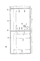
図9は、一実施形態におけるナセル内でのオイルタンクの配置(平面視での配置)を示す図である。
一実施形態では、オイルタンク28は、図3及び図9に示すように、ナセル7の左右方向(図1における風車ロータ2の回転軸12の軸線に直交する水平方向)を長手方向として配置され、隔壁52は、ナセル7の前後方向(図1における風車ロータ2の回転軸12の軸線方向)に沿って該隔壁52の壁面52aが延在するように配置される。
FIG. 9 is a diagram illustrating an arrangement (an arrangement in a plan view) of an oil tank in the nacelle according to an embodiment.
In one embodiment, as shown in FIGS. 3 and 9, the
浮体式の風力発電装置100では、陸上用の風力発電装置や着床式の洋上風力発電装置とは異なり、波の影響によって風力発電装置がロール方向(ナセルの前後方向を回転軸線とする回転方向)にも揺動する。本発明者の検討によれば、浮体式の風力発電装置100において風車ロータ2の回転軸12の軸線に直交する水平方向を長手方向としてオイルタンク28が配置されている場合には、オイルタンク28の内壁のうち風車ロータ2の回転軸12の軸線方向に沿って延在する壁面に、風力発電装置のロール方向の揺動に起因するスロッシングによって大きな圧力がかかることが明らかとなった。
In the floating
図10(a)及び(b)に、浮体式の風力発電装置において風車ロータの回転軸の軸線に直交する水平方向を長手方向としてオイルタンクが配置されている場合に、オイルのスロッシングによってナセルの内壁の壁面にかかる面積平均圧力の時系列の解析結果を示す。図10(a)は、ナセルの前方向の内壁の壁面にかかる面積平均圧力を実線で、ナセルの後方向の内壁の壁面にかかる面積平均圧力を破線で示している。図10(b)は、ナセルの左方向の内壁の壁面にかかる面積平均圧力を実線で、ナセルの右方向の内壁の壁面にかかる面積平均圧力を破線で示している。図10(a)及び(b)を比較すると、オイルタンク28の内壁の壁面のうち風車ロータ2の回転軸12の軸線方向に沿って延在する壁面(図10(b)に示すナセル左方向の壁面及びナセル右方向の壁面)に、風力発電装置のロール方向の揺動に起因するスロッシングによって大きな圧力がかかるタイミング(例えば図中のタイミングA)が存在することがわかる。
10 (a) and 10 (b), when the oil tank is arranged with the horizontal direction orthogonal to the axis of the rotation axis of the wind turbine rotor as the longitudinal direction in the floating wind turbine generator, The time series analysis result of the area average pressure applied to the wall surface of the inner wall is shown. FIG. 10A shows the area average pressure applied to the wall surface of the inner wall in the front direction of the nacelle by a solid line and the area average pressure applied to the wall surface of the inner wall in the rear direction of the nacelle by a broken line. FIG. 10B shows the area average pressure applied to the wall surface of the inner wall in the left direction of the nacelle by a solid line and the area average pressure applied to the wall surface of the inner wall in the right direction of the nacelle by a broken line. 10 (a) and 10 (b), a wall surface extending along the axial direction of the
そこで、上述のように、隔壁52を、ナセルの前後方向(風車ロータ2の回転軸12の軸線方向)に沿って該隔壁52の壁面52aが延在するように配置することにより、浮体式の風力発電装置100におけるロール方向の揺動に起因するスロッシングを効果的に低減することが可能となる。
Therefore, as described above, the
幾つかの実施形態に係るオイルタンク28は、例えば図4において、以下の条件式(A)と条件式(B)の何れか一方と、条件式(C)及び条件式(D)の何れか一方とを満たすよう構成される。
これにより、油圧トランスミッション4の運転状態によらず、オイルタンク28の隔壁52の壁面に垂直な方向のオイルのスロッシングの固有振動数を風力発電装置100全体構造の曲げモードの固有振動数ftowerと異ならせることができる。これにより、オイルタンク28における隔壁52の壁面に垂直な方向のオイルのスロッシングを効果的に抑制することができる。
Accordingly, the natural frequency of oil sloshing in the direction perpendicular to the wall surface of the
以下、上記4つの条件式(A)〜(D)についてさらに詳述する。ロイド船級協会資料によれば、タンク(特に矩形タンク)におけるスロッシングの固有周期Tは、
風力発電装置100が浮体式の風力発電装置である場合、幾つかの実施形態に係るオイルタンク28は、例えば図4において、以下の条件式(E)と条件式(F)の何れか一方と、条件式(G)及び条件式(H)の何れか一方とを満たすよう構成される。
これにより、油圧トランスミッション4の運転状態によらず(オイルタンク28の最高油面高さFmax〜最低油面高さFminの範囲にわたって)、オイルタンク28の隔壁52の壁面に垂直な方向のオイルのスロッシングの固有振動数を浮体に作用する有義波の周波数と異ならせることができる。これにより、オイルタンクにおける隔壁52の壁面に垂直な方向のオイルのスロッシングを効果的に抑制することができる。
Thus, regardless of the operation state of the hydraulic transmission 4 (over the range of the maximum oil level height F max to the minimum oil level height F min of the oil tank 28), the direction perpendicular to the wall surface of the
風力発電装置100が浮体式の風力発電装置である場合、幾つかの実施形態に係るオイルタンク28は、例えば図4において、以下の条件式(I)と条件式(J)の何れか一方と、条件式(K)及び条件式(L)の何れか一方とを満たすよう構成される。
これにより、油圧トランスミッション4の運転状態によらず(オイルタンク28の最高油面高さFmax〜最低油面高さFminの範囲にわたって)、オイルタンク28の隔壁52の壁面に垂直な方向のオイルのスロッシングの固有振動数を、浮体式風力発電装置100における隔壁52の壁面に垂直な方向の動揺の固有振動数と異ならせることができる。これにより、オイルタンク28における隔壁52の壁面に垂直な方向のオイルのスロッシングを効果的に抑制することができる。なお、オイルタンク28の長手方向がナセルの左右方向に一致する実施形態(図3,図9参照)では、好ましくは、隔壁52の壁面がナセルの前後方向に沿う方向であり、この場合、浮体式風力発電装置100における隔壁52の壁面に垂直な方向の動揺の固有振動数は、浮体式風力発電装置100におけるロール方向の動揺の固有振動数に一致する。また、オイルタンク28の長手方向がナセルの前後方向に一致する実施形態では、好ましくは、隔壁52の壁面がナセルの左右方向に沿う方向であり、この場合、浮体式風力発電装置100における隔壁52の壁面に垂直な方向の動揺の固有振動数は、浮体式風力発電装置100におけるピッチ方向の動揺の固有振動数に一致する。
Thus, regardless of the operation state of the hydraulic transmission 4 (over the range of the maximum oil level height F max to the minimum oil level height F min of the oil tank 28), the direction perpendicular to the wall surface of the
図11は、幾つかの実施形態に係るオイルタンク28を含むオイル収容ユニット58の斜視図である。
FIG. 11 is a perspective view of an
幾つかの実施形態に係る風力発電装置100(図1参照)は、図11に示すオイル収容ユニット58を備えている。オイル収容ユニット58は、オイルタンク28と、オイルタンク28から漏れたオイルを貯留可能なオイルパン60とを含む。このため、オイルタンク28から万一オイルが漏れても、漏れたオイルの拡散を抑制することができる。また、オイルパン60は、オイルパン60の内側の空間を仕切るように設けられた多孔板62を更に備えている。一実施形態に係るオイル収容ユニット58は、図11に示すように、格子状に配置された複数の多孔板を含んでいてもよい。これにより、オイルパン60内でのオイルのスロッシングが抑制され、オイルの拡散を効果的に抑制することができる。
A wind turbine generator 100 (see FIG. 1) according to some embodiments includes an
本発明は上述した実施形態に限定されることはなく、上述した実施形態に変形を加えた形態や、これらの形態を適宜組み合わせた形態も含む。 The present invention is not limited to the above-described embodiments, and includes forms obtained by modifying the above-described embodiments and forms obtained by appropriately combining these forms.
2 風車ロータ
4 油圧トランスミッション
6 発電機
7 ナセル
8 風車翼
10 ハブ
12 回転軸
14 タワー
16 係留索
18 浮体
20 油圧ポンプ
22 油圧モータ
24 高圧油ライン
26 低圧油ライン
28 オイルタンク
30 油圧回路
32 供給ライン(オイル供給ライン)
34 リリーフライン(オイル回収ライン)
35 ブーストポンプ
36 モータリング用ライン(オイル供給ライン)
38 モータリング用ポンプ
40 第1ドレインライン(オイル回収ライン)
42 第2ドレインライン(オイル回収ライン)
44 リリーフバルブ
48 第1オイル室
49 オイルヒータ
50 第2オイル室
51 第3オイル室
52 隔壁
53 隔壁
54a,54b 開口部
55a,55b 開口部
56 オイルヒータ
58 オイル収容ユニット
60 オイルパン
62 多孔板
100 風力発電装置
2
34 Relief line (oil recovery line)
35
38
42 Second drain line (oil recovery line)
44
Claims (12)
前記オイルを収容するための第1オイル室及び第2オイル室と、
前記第1オイル室と前記第2オイル室とを仕切る隔壁と、
当該オイルタンク内のオイルを加熱するためのオイルヒータと、
を少なくとも備え、
前記第2オイル室は、前記オイル使用機器にオイルを供給するためのオイル供給ラインに接続可能に構成され、
前記第1オイル室は、前記オイル使用機器からオイルを回収するためのオイル回収ラインに接続可能に構成され、
前記隔壁には、前記第1オイル室と前記第2オイル室との間で前記オイルが移動可能となるように、前記第1オイル室と前記第2オイル室とを連通するための少なくとも二つの開口部が形成されており、
前記少なくとも二つの開口部は、第1開口部及び該第1開口部の下方に設けられた第2開口部を含み、
前記オイルヒータは前記第1オイル室又は前記第2オイル室に設けられ、
前記第2開口部の下端位置は、前記オイルヒータの下端位置より高い
風力発電装置用オイルタンク。 An oil tank that is installed in a nacelle supported by a tower of a wind turbine generator, and that contains oil used in oil using equipment provided in the wind turbine generator,
A first oil chamber and a second oil chamber for containing the oil;
A partition partitioning the first oil chamber and the second oil chamber;
An oil heater for heating the oil in the oil tank;
Comprising at least
The second oil chamber is configured to be connectable to an oil supply line for supplying oil to the oil using device,
The first oil chamber is configured to be connectable to an oil recovery line for recovering oil from the oil using device,
The partition wall has at least two for communicating the first oil chamber and the second oil chamber so that the oil can move between the first oil chamber and the second oil chamber. An opening is formed,
The at least two openings include a first opening and a second opening provided below the first opening,
The oil heater is provided in the first oil chamber or the second oil chamber,
The oil tank for wind power generators , wherein the lower end position of the second opening is higher than the lower end position of the oil heater .
ことを特徴とする請求項1に記載の風力発電装置用オイルタンク。The oil tank for wind power generators according to claim 1 characterized by things.
前記オイルを収容するための第1オイル室及び第2オイル室と、
前記第1オイル室と前記第2オイル室とを仕切る隔壁と、
当該オイルタンク内のオイルを加熱するためのオイルヒータと、
を少なくとも備え、
前記第2オイル室は、前記オイル使用機器にオイルを供給するためのオイル供給ラインに接続可能に構成され、
前記第1オイル室は、前記オイル使用機器からオイルを回収するためのオイル回収ラインに接続可能に構成され、
前記隔壁には、前記第1オイル室と前記第2オイル室との間で前記オイルが移動可能となるように、前記第1オイル室と前記第2オイル室とを連通するための少なくとも二つの開口部が形成されており、
前記風力発電装置は、浮体式の風力発電装置であり、
前記オイルタンクは、前記風力発電装置が備える風車ロータの回転軸線に直交する水平方向を長手方向として配置され、
前記隔壁は、前記風力発電装置が備える風車ロータの回転軸線方向に沿って該隔壁の壁面が延在するように配置される風力発電装置用オイルタンク。 An oil tank that is installed in a nacelle supported by a tower of a wind turbine generator, and that contains oil used in oil using equipment provided in the wind turbine generator,
A first oil chamber and a second oil chamber for containing the oil;
A partition partitioning the first oil chamber and the second oil chamber;
An oil heater for heating the oil in the oil tank;
Comprising at least
The second oil chamber is configured to be connectable to an oil supply line for supplying oil to the oil using device,
The first oil chamber is configured to be connectable to an oil recovery line for recovering oil from the oil using device,
The partition wall has at least two for communicating the first oil chamber and the second oil chamber so that the oil can move between the first oil chamber and the second oil chamber. An opening is formed,
The wind power generator is a floating wind power generator,
The oil tank is disposed with the horizontal direction orthogonal to the rotation axis of the wind turbine rotor included in the wind turbine generator as a longitudinal direction,
The partition wall, wind power generation device oil tank wall surface of the partition wall Ru is arranged to extend along the rotation axis of the wind turbine rotor, wherein the wind turbine generator is provided.
前記オイルを収容するための第1オイル室及び第2オイル室と、
前記第1オイル室と前記第2オイル室とを仕切る隔壁と、
当該オイルタンク内のオイルを加熱するためのオイルヒータと、
を少なくとも備え、
前記第2オイル室は、前記オイル使用機器にオイルを供給するためのオイル供給ラインに接続可能に構成され、
前記第1オイル室は、前記オイル使用機器からオイルを回収するためのオイル回収ラインに接続可能に構成され、
前記隔壁には、前記第1オイル室と前記第2オイル室との間で前記オイルが移動可能となるように、前記第1オイル室と前記第2オイル室とを連通するための少なくとも二つの開口部が形成されており、
以下の条件式(A)と条件式(B)の何れか一方と、条件式(C)及び条件式(D)の何れか一方とを満たすよう構成された風力発電装置用オイルタンク。
A first oil chamber and a second oil chamber for containing the oil;
A partition partitioning the first oil chamber and the second oil chamber;
An oil heater for heating the oil in the oil tank;
Comprising at least
The second oil chamber is configured to be connectable to an oil supply line for supplying oil to the oil using device,
The first oil chamber is configured to be connectable to an oil recovery line for recovering oil from the oil using device,
The partition wall has at least two for communicating the first oil chamber and the second oil chamber so that the oil can move between the first oil chamber and the second oil chamber. An opening is formed,
One and, conditional expressions (C) and conditions either a configured wind power generator oil tank so as to satisfy the formula (D) of the following conditions (A) and condition (B).
前記オイルを収容するための第1オイル室及び第2オイル室と、
前記第1オイル室と前記第2オイル室とを仕切る隔壁と、
当該オイルタンク内のオイルを加熱するためのオイルヒータと、
を少なくとも備え、
前記第2オイル室は、前記オイル使用機器にオイルを供給するためのオイル供給ラインに接続可能に構成され、
前記第1オイル室は、前記オイル使用機器からオイルを回収するためのオイル回収ラインに接続可能に構成され、
前記隔壁には、前記第1オイル室と前記第2オイル室との間で前記オイルが移動可能となるように、前記第1オイル室と前記第2オイル室とを連通するための少なくとも二つの開口部が形成されており、
前記風力発電装置は、浮体式の風力発電装置であり、
以下の条件式(E)と条件式(F)の何れか一方と、条件式(G)及び条件式(H)の何れか一方とを満たすよう構成された風力発電装置用オイルタンク。
A first oil chamber and a second oil chamber for containing the oil;
A partition partitioning the first oil chamber and the second oil chamber;
An oil heater for heating the oil in the oil tank;
Comprising at least
The second oil chamber is configured to be connectable to an oil supply line for supplying oil to the oil using device,
The first oil chamber is configured to be connectable to an oil recovery line for recovering oil from the oil using device,
The partition wall has at least two for communicating the first oil chamber and the second oil chamber so that the oil can move between the first oil chamber and the second oil chamber. An opening is formed,
The wind power generator is a floating wind power generator,
One and the conditional expression (G) and conditions either a configured wind power generator oil tank so as to satisfy the formula (H) in the following condition (E) and conditional expression (F).
前記オイルを収容するための第1オイル室及び第2オイル室と、
前記第1オイル室と前記第2オイル室とを仕切る隔壁と、
当該オイルタンク内のオイルを加熱するためのオイルヒータと、
を少なくとも備え、
前記第2オイル室は、前記オイル使用機器にオイルを供給するためのオイル供給ラインに接続可能に構成され、
前記第1オイル室は、前記オイル使用機器からオイルを回収するためのオイル回収ラインに接続可能に構成され、
前記隔壁には、前記第1オイル室と前記第2オイル室との間で前記オイルが移動可能となるように、前記第1オイル室と前記第2オイル室とを連通するための少なくとも二つの開口部が形成されており、
前記風力発電装置は、浮体式の風力発電装置であり、
以下の条件式(I)と条件式(J)の何れか一方と、条件式(K)及び条件式(L)の何れか一方とを満たすよう構成された風力発電装置用オイルタンク。
A first oil chamber and a second oil chamber for containing the oil;
A partition partitioning the first oil chamber and the second oil chamber;
An oil heater for heating the oil in the oil tank;
Comprising at least
The second oil chamber is configured to be connectable to an oil supply line for supplying oil to the oil using device,
The first oil chamber is configured to be connectable to an oil recovery line for recovering oil from the oil using device,
The partition wall has at least two for communicating the first oil chamber and the second oil chamber so that the oil can move between the first oil chamber and the second oil chamber. An opening is formed,
The wind power generator is a floating wind power generator,
One and the conditional expression (K) and conditions either a configured wind power generator oil tank so as to satisfy the formula (L) of the following conditions (I) and conditional expression (J).
前記オイルを収容するための第1オイル室及び第2オイル室と、
前記第1オイル室と前記第2オイル室とを仕切る隔壁と、
当該オイルタンク内のオイルを加熱するためのオイルヒータと、
を少なくとも備え、
前記第2オイル室は、前記オイル使用機器にオイルを供給するためのオイル供給ラインに接続可能に構成され、
前記第1オイル室は、前記オイル使用機器からオイルを回収するためのオイル回収ラインに接続可能に構成され、
前記隔壁には、前記第1オイル室と前記第2オイル室との間で前記オイルが移動可能となるように、前記第1オイル室と前記第2オイル室とを連通するための少なくとも二つの開口部が形成されており、
前記オイルタンクは直方体状又は立方体状に構成され、
前記隔壁は前記第1オイル室及び前記第2オイル室が直方体状又は立方体状となるように配置される風力発電装置用オイルタンク。 An oil tank that is installed in a nacelle supported by a tower of a wind turbine generator, and that contains oil used in oil using equipment provided in the wind turbine generator,
A first oil chamber and a second oil chamber for containing the oil;
A partition partitioning the first oil chamber and the second oil chamber;
An oil heater for heating the oil in the oil tank;
Comprising at least
The second oil chamber is configured to be connectable to an oil supply line for supplying oil to the oil using device,
The first oil chamber is configured to be connectable to an oil recovery line for recovering oil from the oil using device,
The partition wall has at least two for communicating the first oil chamber and the second oil chamber so that the oil can move between the first oil chamber and the second oil chamber. An opening is formed,
The oil tank is configured as a rectangular parallelepiped or a cube,
The partition wind power generator oil tank the first oil chamber and the second oil chamber Ru are arranged such that the rectangular parallelepiped or cubic shape.
前記オイルタンクから漏れたオイルを貯留可能なオイルパンと、を備える風力発電装置用オイル収容ユニットであって、
前記オイルタンクは、
前記オイルを収容するための第1オイル室及び第2オイル室と、
前記第1オイル室と前記第2オイル室とを仕切る隔壁と、
当該オイルタンク内のオイルを加熱するためのオイルヒータと、
を少なくとも備え、
前記第2オイル室は、前記オイル使用機器にオイルを供給するためのオイル供給ラインに接続可能に構成され、
前記第1オイル室は、前記オイル使用機器からオイルを回収するためのオイル回収ラインに接続可能に構成され、
前記隔壁には、前記第1オイル室と前記第2オイル室との間で前記オイルが移動可能となるように、前記第1オイル室と前記第2オイル室とを連通するための少なくとも二つの開口部が形成されており、
前記オイルパンは、該オイルパンの内側の空間を仕切るように設けられた多孔板を更に備える風力発電装置用オイル収容ユニット。 An oil tank that is installed in a nacelle supported by a tower of a wind turbine generator, and that contains oil used in oil-using equipment included in the wind turbine generator;
An oil storage unit for a wind turbine generator comprising an oil pan capable of storing oil leaked from the oil tank,
The oil tank is
A first oil chamber and a second oil chamber for containing the oil;
A partition partitioning the first oil chamber and the second oil chamber;
An oil heater for heating the oil in the oil tank;
Comprising at least
The second oil chamber is configured to be connectable to an oil supply line for supplying oil to the oil using device,
The first oil chamber is configured to be connectable to an oil recovery line for recovering oil from the oil using device,
The partition wall has at least two for communicating the first oil chamber and the second oil chamber so that the oil can move between the first oil chamber and the second oil chamber. An opening is formed,
The oil pan may further wind power generation device oil accommodating unit Ru provided with a perforated plate which is provided so as to partition the inner space of the oil pan.
前記オイルタンクのオイルを使用するオイル使用機器と、
少なくとも一本の風車翼を含む風車ロータと、
前記風車ロータの回転エネルギーが伝達されて駆動される発電機と、
前記オイルタンク、前記オイル使用機器及び前記発電機を収容するナセルと、
前記ナセルを支持するタワーと、
を備える風力発電装置。 The oil tank according to any one of claims 1 to 9 ,
An oil using device that uses the oil in the oil tank;
A windmill rotor including at least one windmill blade;
A generator to which the rotational energy of the wind turbine rotor is transmitted and driven;
A nacelle that houses the oil tank, the oil-using device, and the generator;
A tower that supports the nacelle;
A wind power generator comprising:
Priority Applications (2)
| Application Number | Priority Date | Filing Date | Title |
|---|---|---|---|
| JP2014108648A JP6208625B2 (en) | 2014-05-27 | 2014-05-27 | Oil tank for wind power generator, oil storage unit, and wind power generator |
| EP15156772.4A EP2949986B1 (en) | 2014-05-27 | 2015-02-26 | Oil tank for wind turbine generator, oil storing unit and wind turbine generator |
Applications Claiming Priority (1)
| Application Number | Priority Date | Filing Date | Title |
|---|---|---|---|
| JP2014108648A JP6208625B2 (en) | 2014-05-27 | 2014-05-27 | Oil tank for wind power generator, oil storage unit, and wind power generator |
Publications (3)
| Publication Number | Publication Date |
|---|---|
| JP2015224566A JP2015224566A (en) | 2015-12-14 |
| JP2015224566A5 JP2015224566A5 (en) | 2016-06-16 |
| JP6208625B2 true JP6208625B2 (en) | 2017-10-04 |
Family
ID=52577760
Family Applications (1)
| Application Number | Title | Priority Date | Filing Date |
|---|---|---|---|
| JP2014108648A Expired - Fee Related JP6208625B2 (en) | 2014-05-27 | 2014-05-27 | Oil tank for wind power generator, oil storage unit, and wind power generator |
Country Status (2)
| Country | Link |
|---|---|
| EP (1) | EP2949986B1 (en) |
| JP (1) | JP6208625B2 (en) |
Families Citing this family (7)
| Publication number | Priority date | Publication date | Assignee | Title |
|---|---|---|---|---|
| EP3372825A1 (en) | 2017-03-07 | 2018-09-12 | Adwen GmbH | Nacelle having liquid retaining properties |
| EP3372823A1 (en) * | 2017-03-07 | 2018-09-12 | Adwen GmbH | Nacelle comprising multifunctional components |
| CN107299871B (en) * | 2017-04-19 | 2023-03-14 | 内蒙古科技大学 | Oil saving device for recycling shaking energy of oil in vehicle-mounted oil tank |
| KR20220124204A (en) | 2020-01-08 | 2022-09-13 | 베스타스 윈드 시스템스 에이/에스 | Main bearing housing of wind turbine |
| JP7538869B2 (en) | 2020-01-08 | 2024-08-22 | ヴェスタス ウィンド システムズ エー/エス | Wind turbine main bearing housing |
| CN112412704A (en) * | 2020-11-20 | 2021-02-26 | 田剑辉 | Power generation windmill with energy-saving and electricity-capacitance functions for power equipment |
| EP4177462A1 (en) * | 2021-11-09 | 2023-05-10 | Terawind GmbH | Device for converting wind energy into electrical energy |
Family Cites Families (11)
| Publication number | Priority date | Publication date | Assignee | Title |
|---|---|---|---|---|
| JP2872914B2 (en) * | 1994-08-25 | 1999-03-24 | 株式会社日立製作所 | Gear transmission |
| US5611411A (en) * | 1996-05-10 | 1997-03-18 | Florida Power Corporation | Turbine lubrication oil filtration safeguard system |
| JP2003176774A (en) * | 2001-12-10 | 2003-06-27 | Kyowa Engineering Consultants Co Ltd | Wind power generation device |
| CA2483359C (en) * | 2002-04-24 | 2007-12-11 | Vestas Wind Systems A/S | Wind turbine, hydraulic system, air bleed system and method of controlling at least two wind turbine blades |
| JP2007107409A (en) * | 2005-10-12 | 2007-04-26 | Yanmar Co Ltd | Wind power generation device |
| ES2396138T3 (en) * | 2008-06-02 | 2013-02-19 | Vestas Wind Systems A/S | A lubrication system for a gear system for a wind turbine |
| CN102575650B (en) * | 2009-10-23 | 2015-05-20 | 维斯塔斯风力系统有限公司 | A lubrication system for a gear system providing emergency lubrication |
| CN102232161A (en) * | 2010-02-08 | 2011-11-02 | 三菱重工业株式会社 | Lubricating oil heating mechanism, gear mechanism, and wind power generation device |
| DE102011008672A1 (en) | 2011-01-15 | 2012-07-19 | Hydac Filtertechnik Gmbh | Device for lubricating a gearbox and a bearing |
| DE102011080359A1 (en) * | 2011-05-31 | 2012-12-06 | Siemens Aktiengesellschaft | Wind turbine gearbox for use in wind power plant, has oil-sealed connection part including regulating device that regulates inflow of transmission oil from external oil reservoir into oil sump in dependent on oil temperature |
| ES2396813B1 (en) * | 2011-06-28 | 2014-01-17 | Gamesa Innovation & Technology, S.L. | OIL LEVEL MAINTENANCE SYSTEM. |
-
2014
- 2014-05-27 JP JP2014108648A patent/JP6208625B2/en not_active Expired - Fee Related
-
2015
- 2015-02-26 EP EP15156772.4A patent/EP2949986B1/en not_active Not-in-force
Also Published As
| Publication number | Publication date |
|---|---|
| EP2949986B1 (en) | 2017-08-02 |
| EP2949986A1 (en) | 2015-12-02 |
| JP2015224566A (en) | 2015-12-14 |
Similar Documents
| Publication | Publication Date | Title |
|---|---|---|
| JP6208625B2 (en) | Oil tank for wind power generator, oil storage unit, and wind power generator | |
| US8833070B2 (en) | Low-drag hydro-pneumatic power cylinder and system | |
| EP2988001B1 (en) | Renewable energy power generating apparatus and operation method of the same | |
| JP2015224566A5 (en) | ||
| BRPI1004764B1 (en) | wave power converter | |
| KR20130100898A (en) | Hydrodynamic Cycle Generation Technology | |
| KR101345225B1 (en) | The Generating System That Used Waves | |
| US20140348641A1 (en) | Low-drag hydro-pneumatic power cylinder and system | |
| CN103097239A (en) | Azimuth propeller | |
| CN108026941B (en) | Working oil tank for power generation system and method for sealing working oil in working oil tank | |
| KR20150134481A (en) | Hydraulic Power Generation Apparatus For Vessel | |
| WO2023275666A1 (en) | Energy converter for ocean waves and method for using thereof | |
| KR20150088797A (en) | Floating marine current turbine | |
| US20120193920A1 (en) | Tidal power generating module and tidal power generation method using the same | |
| CN206319988U (en) | A kind of various dimensions float-type Wave power generation device | |
| KR20150144940A (en) | Ballast Water Tank of Barge Mounted Power Plant | |
| KR101413612B1 (en) | foloating-type wind power generator | |
| JP2012215121A (en) | Wave power generation apparatus | |
| KR100853517B1 (en) | Hydroelectric system using high and low tide | |
| KR101726605B1 (en) | Semi floating type waterpower generator | |
| JP2022521742A (en) | Hydroelectric power generator | |
| KR20120047609A (en) | Vessel | |
| US8006493B2 (en) | Method and machine for converting heat to power | |
| JP5935034B2 (en) | Buoyancy hollow falling water generator | |
| KR20190093396A (en) | Wind power generation apparatus |
Legal Events
| Date | Code | Title | Description |
|---|---|---|---|
| A521 | Written amendment |
Free format text: JAPANESE INTERMEDIATE CODE: A523 Effective date: 20160426 |
|
| A621 | Written request for application examination |
Free format text: JAPANESE INTERMEDIATE CODE: A621 Effective date: 20160426 |
|
| A131 | Notification of reasons for refusal |
Free format text: JAPANESE INTERMEDIATE CODE: A131 Effective date: 20170331 |
|
| A977 | Report on retrieval |
Free format text: JAPANESE INTERMEDIATE CODE: A971007 Effective date: 20170330 |
|
| A521 | Written amendment |
Free format text: JAPANESE INTERMEDIATE CODE: A523 Effective date: 20170517 |
|
| TRDD | Decision of grant or rejection written | ||
| A01 | Written decision to grant a patent or to grant a registration (utility model) |
Free format text: JAPANESE INTERMEDIATE CODE: A01 Effective date: 20170901 |
|
| A61 | First payment of annual fees (during grant procedure) |
Free format text: JAPANESE INTERMEDIATE CODE: A61 Effective date: 20170907 |
|
| R150 | Certificate of patent or registration of utility model |
Ref document number: 6208625 Country of ref document: JP Free format text: JAPANESE INTERMEDIATE CODE: R150 |
|
| LAPS | Cancellation because of no payment of annual fees |