JP6179441B2 - Engine control device - Google Patents
Engine control device Download PDFInfo
- Publication number
- JP6179441B2 JP6179441B2 JP2014071513A JP2014071513A JP6179441B2 JP 6179441 B2 JP6179441 B2 JP 6179441B2 JP 2014071513 A JP2014071513 A JP 2014071513A JP 2014071513 A JP2014071513 A JP 2014071513A JP 6179441 B2 JP6179441 B2 JP 6179441B2
- Authority
- JP
- Japan
- Prior art keywords
- fuel
- engine
- engine control
- control device
- combustion chamber
- Prior art date
- Legal status (The legal status is an assumption and is not a legal conclusion. Google has not performed a legal analysis and makes no representation as to the accuracy of the status listed.)
- Active
Links
- 239000000446 fuel Substances 0.000 claims description 89
- 238000002485 combustion reaction Methods 0.000 claims description 65
- CBENFWSGALASAD-UHFFFAOYSA-N Ozone Chemical compound [O-][O+]=O CBENFWSGALASAD-UHFFFAOYSA-N 0.000 claims description 45
- 238000002347 injection Methods 0.000 claims description 41
- 239000007924 injection Substances 0.000 claims description 41
- 230000006835 compression Effects 0.000 claims description 39
- 238000007906 compression Methods 0.000 claims description 39
- 230000001133 acceleration Effects 0.000 claims description 20
- 239000000203 mixture Substances 0.000 claims description 19
- 230000007246 mechanism Effects 0.000 claims description 12
- 238000001816 cooling Methods 0.000 claims description 11
- 230000007704 transition Effects 0.000 claims description 8
- 239000007789 gas Substances 0.000 description 37
- MWUXSHHQAYIFBG-UHFFFAOYSA-N Nitric oxide Chemical compound O=[N] MWUXSHHQAYIFBG-UHFFFAOYSA-N 0.000 description 18
- 239000000779 smoke Substances 0.000 description 16
- 239000003054 catalyst Substances 0.000 description 10
- 239000007921 spray Substances 0.000 description 5
- 238000005516 engineering process Methods 0.000 description 4
- 239000003502 gasoline Substances 0.000 description 4
- 238000007254 oxidation reaction Methods 0.000 description 4
- 238000011144 upstream manufacturing Methods 0.000 description 4
- 230000008859 change Effects 0.000 description 3
- 238000010586 diagram Methods 0.000 description 3
- 238000006243 chemical reaction Methods 0.000 description 2
- 238000009413 insulation Methods 0.000 description 2
- 239000012212 insulator Substances 0.000 description 2
- 230000035515 penetration Effects 0.000 description 2
- 230000001052 transient effect Effects 0.000 description 2
- 230000005540 biological transmission Effects 0.000 description 1
- 239000000567 combustion gas Substances 0.000 description 1
- 239000000498 cooling water Substances 0.000 description 1
- 230000001934 delay Effects 0.000 description 1
- 238000010891 electric arc Methods 0.000 description 1
- 239000002828 fuel tank Substances 0.000 description 1
- 230000006872 improvement Effects 0.000 description 1
- 239000007788 liquid Substances 0.000 description 1
- 238000000034 method Methods 0.000 description 1
- 230000004048 modification Effects 0.000 description 1
- 238000012986 modification Methods 0.000 description 1
- 239000002245 particle Substances 0.000 description 1
- 238000005192 partition Methods 0.000 description 1
- 238000000746 purification Methods 0.000 description 1
- 230000009467 reduction Effects 0.000 description 1
- 238000010992 reflux Methods 0.000 description 1
- 230000004043 responsiveness Effects 0.000 description 1
- 230000000979 retarding effect Effects 0.000 description 1
- 239000000243 solution Substances 0.000 description 1
- 239000004071 soot Substances 0.000 description 1
- 230000006641 stabilisation Effects 0.000 description 1
- 238000011105 stabilization Methods 0.000 description 1
- 238000013517 stratification Methods 0.000 description 1
- XLYOFNOQVPJJNP-UHFFFAOYSA-N water Substances O XLYOFNOQVPJJNP-UHFFFAOYSA-N 0.000 description 1
Images


Landscapes
- Exhaust-Gas Circulating Devices (AREA)
- Output Control And Ontrol Of Special Type Engine (AREA)
- Electrical Control Of Air Or Fuel Supplied To Internal-Combustion Engine (AREA)
- Combined Controls Of Internal Combustion Engines (AREA)
Description
本開示は、エンジンの制御装置に関する。 The present disclosure relates to an engine control device.
近年、低負荷時に空燃比(A/F)の値が30を超えるようなリーン領域を用いる車両用のエンジンにおいて、加速時には、窒素酸化物(NOx)の生成量が多くなるA/Fの値の中間領域、例えば、空気過剰率をλとして、1<λ<2程度の領域を避けて、λ≦1領域を用いる場合がある。λ=1は、A/F=14.7(理論空燃比)に相当する。 In recent years, in an engine for a vehicle using a lean region in which the value of air-fuel ratio (A / F) exceeds 30 at low load, the value of A / F at which the amount of nitrogen oxide (NOx) generated increases during acceleration. In some cases, for example, the region λ ≦ 1 is used while avoiding the region of about 1 <λ <2, where λ is the excess air ratio. λ = 1 corresponds to A / F = 14.7 (theoretical air-fuel ratio).
このようなエンジンにおいては、加速後の過渡期に燃焼室に吸入される新気量が多く、燃料が増量されることから、スモーク(煤)が増大するという懸念がある。 In such an engine, there is a concern that smoke (soot) increases because the amount of fresh air taken into the combustion chamber during the transition period after acceleration increases and the amount of fuel increases.
下記の特許文献1には、エンジンに吸入された新気量とエンジン回転数とに応じて排気スモークが生じない燃料噴射量の最大値を設定し、燃料噴射量をこの最大値で制限することにより、燃料噴射量を実際の吸入空気量に対してスモーク(煤)が生じない範囲に設定するディーゼルエンジンが記載されている。これにより、エンジンへの燃料噴射量が実際の吸入空気量に対してスモークが生じない範囲に設定されるようになるため、加速等の過渡運転時に排気再循環(EGR)の作動遅れ等によるスモークの発生が防止される。 In Patent Document 1 below, the maximum value of the fuel injection amount that does not cause exhaust smoke is set according to the amount of fresh air sucked into the engine and the engine speed, and the fuel injection amount is limited by this maximum value. Describes a diesel engine in which the fuel injection amount is set in a range in which smoke does not occur with respect to the actual intake air amount. As a result, the amount of fuel injected into the engine is set in a range in which smoke does not occur with respect to the actual intake air amount. Therefore, the smoke caused by exhaust gas recirculation (EGR) operation delay during transient operation such as acceleration, etc. Is prevented from occurring.
しかしながら、特許文献1に記載された技術では、加速時等の過渡運転時において、燃料噴射量をスモークが生じない範囲に設定していることから、所定の燃料が噴射されず、エンジンのトルク不足により加速の応答性が低下するという問題がある。 However, in the technique described in Patent Document 1, since the fuel injection amount is set in a range in which smoke does not occur during transient operation such as acceleration, predetermined fuel is not injected and engine torque is insufficient. As a result, there is a problem that the responsiveness of acceleration is lowered.
本開示の技術は、かかる点に鑑みてなされたものであり、その目的とするところは、加速時等の高負荷領域においても、スモークを消失させて低エミッション性能を向上し、且つ、加速性能を向上させることにある。 The technology of the present disclosure has been made in view of the above points, and the purpose of the technology is to eliminate smoke and improve low emission performance even in a high load region such as during acceleration, and to accelerate performance. Is to improve.
上記の課題を解決するため、本発明は、エンジンの低負荷時から高負荷時への加速時に燃料を所定量だけ増量すると共に、燃料の燃焼前及び燃焼中にオゾン(O3)を添加することを特徴とする。 In order to solve the above problems, the present invention increases the amount of fuel by a predetermined amount when accelerating the engine from a low load to a high load, and adds ozone (O 3 ) before and during combustion of the fuel. It is characterized by that.
具体的には、本発明は、エンジンの制御装置を対象とし、次のような解決手段を講じた。 Specifically, the present invention is directed to an engine control device and has taken the following solutions.
すなわち、第1の発明は、エンジン本体と、エンジン本体を運転するよう構成された制御器とを備え、制御器は、エンジン本体における圧縮行程の後半以降に燃焼室に燃料を供給し、新気量が相対的に多い空気過剰率λが2よりも大きい低負荷領域から、EGR率(気筒内の全ガス量に対する排気再循環ガスの量の割合)が相対的に高く、新気量が相対的に少ない空気過剰率λが1.05未満の高負荷領域への加速時において、新気量が高負荷領域の新気量にまで減量する前の加速過渡期では、燃料を所定量に増量し、且つ燃焼前及び燃焼中に新気が活性化するようにオゾンを添加し、空気過剰率λが2よりも大きい低負荷領域では、燃焼室内において局所的にリッチな状態の混合気層の周辺に新気が位置するように、圧縮行程の後半以降に燃焼室に燃料を供給するものである。 That is, the first invention includes an engine body and a controller configured to operate the engine body. The controller supplies fuel to the combustion chamber after the second half of the compression stroke in the engine body, and From the low load region where the excess air ratio λ is relatively larger than 2, the EGR rate (ratio of the amount of exhaust gas recirculation to the total gas amount in the cylinder) is relatively high, and the fresh air amount is relatively During acceleration to a high load region where the excess air ratio λ is less than 1.05, the fuel is increased to a predetermined amount in the acceleration transition period before the new air amount is reduced to the new air amount in the high load region. In addition , ozone is added so that fresh air is activated before and during combustion, and in a low load region where the excess air ratio λ is greater than 2, the mixture layer locally rich in the combustion chamber It burns after the second half of the compression stroke so that fresh air is located in the vicinity. And it supplies the fuel to the chamber.
これによれば、圧縮行程の後半以降の燃料噴射に伴う混合気密度のむらにより、混合気に局所的なリッチ状態が生じてスモークが生成される。本開示においては、局所的にリッチな状態の周辺に位置する新気(リーン域にある新気)をオゾンによって活性化し、さらに、膨張行程において燃焼を継続させることにより、生成されたスモークを焼失させることができる。その結果、燃料を増量することができるので、低エミッション性能と加速性能とを向上することができる。 According to this, a local rich state is generated in the air-fuel mixture due to the non-uniformity of the air-fuel mixture density due to fuel injection after the latter half of the compression stroke, and smoke is generated. In the present disclosure, fresh air located in the vicinity of a locally rich state (fresh air in the lean region) is activated by ozone, and further, combustion is continued in the expansion stroke, thereby burning the generated smoke. Can be made. As a result, the amount of fuel can be increased, so that low emission performance and acceleration performance can be improved.
第2の発明は、上記第1の発明において、加速過渡期における燃料の所定量は、空気過剰率λが1となる量とするものである。 According to a second aspect, in the first aspect, the predetermined amount of fuel in the acceleration transition period is an amount at which the excess air ratio λ is 1.
これによれば、空気過剰率λを1とするため、高い燃焼性と、いずれのエンジンにも広く装備される三元触媒によって低エミッション性能とが確保され、加速性能を確実に向上させることができる。尚、高負荷領域においては、エンジン本体の負荷の増大に伴い、空気過剰率λを2.5以上とすることが困難になることから、すなわち、燃料噴射量が増えるのに伴って大量の空気を気筒内に導入しなければならなくなる反面、設定されるEGR率は高く、空気量が不足することから、空気過剰率λを、2.5以下で且つ1.05よりも大きい中間空燃比とするのではなく、1に設定することは好ましい。 According to this, since the excess air ratio λ is 1, high flammability and low emission performance are ensured by the three-way catalyst widely installed in any engine, and the acceleration performance can be reliably improved. it can. In the high load region, it becomes difficult to set the excess air ratio λ to 2.5 or more as the load on the engine body increases. That is, as the fuel injection amount increases, a large amount of air However, since the set EGR rate is high and the amount of air is insufficient, the excess air ratio λ is set to an intermediate air-fuel ratio that is 2.5 or less and greater than 1.05. It is preferable to set it to 1 instead of.
第3の発明は、上記第1の発明において、エンジン本体に設けられた気筒内に排気ガスの一部を還流させるように設けられた排気再循環(EGR)手段をさらに備え、制御器は、高負荷領域において、排気再循環(EGR)手段による排気再循環率を相対的に高く設定し、且つ、低負荷領域における排気再循環(EGR)率よりも高く設定するものである。 According to a third invention, in the first invention, an exhaust gas recirculation (EGR) means is provided so as to recirculate a part of the exhaust gas in a cylinder provided in the engine body. In the high load region, the exhaust gas recirculation rate by the exhaust gas recirculation (EGR) means is set to be relatively high and higher than the exhaust gas recirculation (EGR) rate in the low load region.
これによれば、高負荷領域においては、低温燃焼(1500K以下の低温燃焼)且つ緩慢燃焼を実現できるため、燃焼温度及び急激な燃焼に伴う燃焼室内の最高圧力(Pmax)に起因するNOx生成の増大が抑制できるので、低エミッション性能が向上し、且つ燃焼時の騒音を抑制することができる。また、EGRを用いることにより、空気過剰率λを1にすることが容易となる。一方、低負荷領域においては、圧縮着火方式のエンジンの場合は、EGRによって着火が抑制される。また、成層着火を実現でき、且つ、NOxの低減を図ることができる。 According to this, low temperature combustion (low temperature combustion of 1500 K or less) and slow combustion can be realized in the high load region, so that NOx generation due to the combustion temperature and the maximum pressure (Pmax) in the combustion chamber accompanying rapid combustion is achieved. Since the increase can be suppressed, low emission performance can be improved and noise during combustion can be suppressed. Further, by using EGR, it becomes easy to set the excess air ratio λ to 1. On the other hand, in the low load region, in the case of a compression ignition engine, ignition is suppressed by EGR. Further, stratified ignition can be realized, and NOx can be reduced.
第4の発明は、上記第3の発明において、排気再循環手段には、排気ガスを冷却する冷却機構が設けられているものである。 In a fourth aspect based on the third aspect, the exhaust gas recirculation means is provided with a cooling mechanism for cooling the exhaust gas.
これによれば、気筒内に導入されるガス温度が低くでき、密度が高い空気を導入できることから、吸気充填効率の低下を抑制できると共に、低温燃焼を実現でき、NOxの生成を抑制することができる。 According to this, since the temperature of the gas introduced into the cylinder can be lowered and high-density air can be introduced, it is possible to suppress a decrease in intake charging efficiency, realize low-temperature combustion, and suppress the generation of NOx. it can.
第5の発明は、上記第1〜第4の発明において、圧縮行程の後半以降の燃焼室への燃料の供給は、圧縮行程に続く膨張行程で行われるリタード噴射とするものである。 According to a fifth aspect of the present invention, in the first to fourth aspects of the present invention, the fuel is supplied to the combustion chamber after the latter half of the compression stroke by retarded injection performed in the expansion stroke following the compression stroke.
これによれば、燃焼時の圧力の急激な変化(dp/dt)を抑制できるので、騒音の低減を図ることができる。 According to this, since a rapid change (dp / dt) in pressure during combustion can be suppressed, noise can be reduced.
以上説明したように、前記のエンジンの制御装置によると、加速時等の高負荷領域においても、スモークを消失させて低エミッション性能を向上し、且つ、加速性能を向上させることができる。 As described above, according to the engine control apparatus, smoke can be eliminated to improve low emission performance and acceleration performance even in a high load region such as during acceleration.
以下、エンジンの制御装置の一実施形態を図面に基づいて説明する。以下の説明は、例示である。 Hereinafter, an embodiment of an engine control device will be described with reference to the drawings. The following description is exemplary.
(エンジンシステムの全体構成)
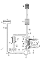
図1及び図2は、本実施形態に係るエンジンシステム1の構成を示している。エンジンシステム1は、車両に搭載されるシステムである。エンジンシステム1は、エンジン本体(以下、単に「エンジン」という)10と、該エンジン10に付随する種々のアクチュエータ、種々のセンサ及び該センサからの信号に基づきアクチュエータを制御するPCM(Powertrain Control Module:制御器)100とを含む。
(Overall configuration of engine system)
1 and 2 show the configuration of the engine system 1 according to the present embodiment. The engine system 1 is a system mounted on a vehicle. The engine system 1 includes an engine main body (hereinafter simply referred to as “engine”) 10, various actuators associated with the
エンジン10の出力軸は、図示しないが、変速機を介して駆動輪に連結されている。エンジン10の出力が駆動輪に伝達されることによって車両が推進する。エンジン10は、シリンダブロック12と、その上に載置されるシリンダヘッド13とを備えており、シリンダブロック12の内部に複数の気筒11が形成されている(図1では、1つのみを示す。)。シリンダブロック12及びシリンダヘッド13の内部には、冷却水が流れるウォータージャケット(図示せず)が形成されている。
Although not shown, the output shaft of the
各気筒11内には、ピストン15がそれぞれ摺動自在に嵌挿されており、ピストン15は、気筒11及びシリンダヘッド13と共に燃焼室を区画している。本実施形態では、燃焼室は、いわゆるペントルーフ型であり、その天井面(シリンダヘッド13の下面)は吸気側及び排気側の2つの傾斜面からなる三角屋根状をなしている。ピストン15の冠面は、天井面に対応した凸形状をなしており、冠面の中心部には、凹状のキャビティ15aが形成されている。尚、天井面及びピストン15の冠面の形状は、後述する高い幾何学的圧縮比が可能であれば、どのような形状であってもよく、例えば、天井面及びピストン15の冠面(キャビティ15aを除く部分)の両方が、気筒11の中心軸に対して垂直な面で構成されていてもよく、天井面が前記のように三角屋根状をなす一方、ピストン15の冠面(キャビティ15aを除く部分)が気筒11の中心軸に対して垂直な面で構成されていてもよい。
A
シリンダヘッド13には、気筒11毎に2つの吸気ポート18が形成され、それぞれがシリンダヘッド13の下面(燃焼室の天井面における吸気側の傾斜面)に開口することにより燃焼室に連通している。同様に、シリンダヘッド13には、気筒11毎に2つの排気ポート19が形成され、それぞれがシリンダヘッド13の下面(燃焼室の天井面の排気側の傾斜面)に開口することにより燃焼室に連通している。
The
また、シリンダヘッド13には、吸気弁21及び排気弁22が、それぞれ吸気ポート18及び排気ポート19を燃焼室から遮断(閉)することができるように配設されている。吸気弁21は吸気弁駆動機構により、排気弁22は排気弁駆動機構により、それぞれ駆動される。吸気弁21及び排気弁22は所定のタイミングで往復動して、それぞれ吸気ポート18及び排気ポート19を開閉し、気筒11内のガス交換を行う。吸気弁駆動機構及び排気弁駆動機構は、図示は省略するが、それぞれ、クランクシャフトに駆動連結された吸気カムシャフト及び排気カムシャフトを有している。これらのカムシャフトは、クランクシャフトの回転と同期して回転する。吸気弁駆動機構及び排気弁駆動機構は、この例では、吸気カムシャフトの位相を所定の角度範囲内で連続的に変更可能な、液圧式又は電動式の位相可変機構(Variable Valve Timing:VVT)23を、少なくとも含んで構成されている(図2を参照。)。尚、VVT23と共に、弁リフト量を変更可能なリフト可変機構を備えるようにしてもよい。リフト可変機構は、リフト量を連続的に変更可能なCVVL(Continuous Variable Valve Lift)としてもよい。
The
各気筒11の吸気ポート18は、図1において明示されない吸気マニホールドを介して吸気通路30に連通している。また、各気筒11の排気ポート19は、同様に明示されない排気マニホールドを介して排気通路40に連通している。
The
吸気通路30には、エアクリーナ31と、各気筒11への吸入空気量を調節するスロットル弁33とが、上流から下流に向かって順次配設されている。
In the
排気通路40には、排気ガス中の有害成分を浄化する排気浄化装置として、直キャタリスト41とアンダーフットキャタリスト42とが、上流側から下流側に向かって順次配設されている。直キャタリスト41及びアンダーフットキャタリスト42は、それぞれ、筒状ケースと、該ケース内の流路に配置した三元触媒とを備えて構成されている。
In the
吸気通路30におけるスロットル弁33の下流側部分と、排気通路40における直キャタリスト41の上流側部分とは、排気ガスの一部を吸気通路30に還流するための高圧EGR通路510によって接続されている。高圧EGR通路510には、排気ガスの吸気通路30への還流量を調整するための高圧EGR弁511、及び排気ガスを冷却するための水冷式のEGRクーラ512が配設されている。高圧EGR通路510、高圧EGR弁511及びEGRクーラ512を含めて高圧EGRシステム51(排気再循環手段)が構成される。
The downstream portion of the
エンジン10において、シリンダヘッド13における気筒11の中心軸上には、気筒内(燃焼室内)に燃料を直接噴射するインジェクタ34が配設されている。インジェクタ34は、例えばブラケットを使用する等の周知の構造でシリンダヘッド13に取付固定されている。インジェクタ34の先端は、燃焼室の天井部の中心に臨んでいる。
In the
インジェクタ34は、本実施形態においては、外開弁式のインジェクタである。つまり、その構成の詳細な図示は省略するが、気筒11内に燃料を噴射するノズル口を開閉する外開弁を有し、外開弁が気筒11側にリフトすることによってノズル口を開放する。このとき、燃料はノズル口から気筒11内に該気筒11の中心軸を中心とするコーン状(詳しくはホローコーン状)に噴射される。外開弁のリフト量が大きいほど、ノズル口の開度が大きくなって、該ノズル口から気筒11内に噴射される燃料噴霧のペネトレーションが大きくなる(長くなる)。さらに、単位時間当たりに噴射される燃料量が多くなり、且つ燃料噴霧の粒径が大きくなる。尚、インジェクタ34は、外開弁式に限らず、多噴孔型のインジェクタとしてもよい。
In the present embodiment, the
燃料供給システム35は、外開弁を駆動するための電気回路と、インジェクタ34に燃料を供給する燃料供給系とを備えている。PCM100は、所定のタイミングで、リフト量に応じた電圧を有する噴射信号を電気回路に出力することにより、該電気回路を介して外開弁を作動させて、所望量の燃料を気筒11内に噴射させる。噴射信号の非出力時(噴射信号の電圧が0であるとき)には、外開弁によりノズル口が閉じられた状態となる。こうしてPCM100は、外開弁の作動を制御して、インジェクタ34のノズル口からの燃料噴射及び該燃料噴射時におけるリフト量を制御する。
The
燃料供給系には、図示しない高圧燃料ポンプ及びコモンレールが設けられており、高圧燃料ポンプは、低圧燃料ポンプを介して燃料タンクより供給された燃料をコモンレールに圧送し、コモンレールは、圧送された燃料を所定の燃料圧力で蓄える。その後、インジェクタ34が作動することによって、コモンレールに蓄えられている燃料がノズル口から噴射される。
The fuel supply system is provided with a high-pressure fuel pump and a common rail (not shown). The high-pressure fuel pump pumps fuel supplied from the fuel tank via the low-pressure fuel pump to the common rail. Is stored at a predetermined fuel pressure. Thereafter, when the
ここで、エンジン10の燃料は、本実施形態ではガソリンであるが、バイオエタノール等を含むガソリンであってもよく、少なくともガソリンを含む燃料(液体燃料)であれば、どのような燃料であってもよい。
Here, the fuel of the
また、エンジン10の燃焼室内には、オゾン発生器36が配設されている。オゾン発生器36は、例えばねじ等の周知の構造によって、シリンダヘッド13に固定されている。オゾン発生器36の先端部は燃焼室の天井部に臨んでいる。オゾン発生器36の先端部は、インジェクタ34のノズル口の近傍に位置する。オゾン発生器36は、絶縁されて配置された1つの電極(正電極)を有している。オゾン発生器36は、オゾン発生システム37によって駆動される。オゾン発生システム37は、オゾン発生回路を有している。オゾン発生システム37は、PCM100からの制御信号を受けて、高圧の高周波電圧をオゾン発生器36に出力する。オゾン発生器36は、高周波電圧が印加されると、電極とシリンダブロック12又はシリンダヘッド13との間にオゾン(O3)を発生させる。オゾン発生器36に印加する高周波電圧値又は周波数を変更することによって、オゾンの濃度を調整することができる。尚、オゾン発生器36の配置及び構成は、上記の構成に限定されない。
An
PCM100は、周知のマイクロコンピュータをベースとするコントローラであって、プログラムを実行する中央演算処理装置(CPU)と、例えばRAM及びROMにより構成されてプログラム及びデータを格納するメモリと、電気信号の入出力をする入出力(I/O)バスとを備えている。
The
PCM100には、車速を検出する車速センサ71、アクセル開度を検出するアクセル開度センサ72、及びエンジン10の回転数を検出するエンジン回転数センサ73の各センサが接続されている。
Connected to the
吸気通路30には、吸気通路30を流れる新気の流量(及び温度)を検出するエアフローセンサ74が配設されている。エアフローセンサ74は、検出した流量及び外気温度をPCM100に出力する。
An
サージタンク38には、燃焼室に供給される空気の圧力を検出する吸気圧センサ75が取り付けられると共に、排気通路40には、排気の圧力を検出する排気圧センサ76が配設されている。各センサ75、76は、PCM100と接続されており、その検出値をPCM100に出力する。
An
PCM100は、前述した各センサ等からの信号に基づいて、エンジン10の運転状態を判断し、それに対応するエンジン10の制御パラメータを設定する。PCM100は、各制御パラメータに対応する信号を、スロットル弁33、燃料供給システム35、VVT23、高圧EGR弁511及びオゾン発生システム37等に出力する。
The
尚、本実施形態の一変形例として、エンジン本体10を、吸気通路30にコンプレッサが配設され、排気通路40にコンプレッサと同軸のタービンが配設されたターボ過給機を有する過給器付きエンジンとしてもよい。さらに、ターボ過給機は、可変ノズルを有するVGT(Variable Geometry Turbo)であってもよい。
As a modification of the present embodiment, the
また、過給器付きエンジンとする場合には、吸気通路30におけるエアクリーナ31の下流側部分と、排気通路40における直キャタリスト41の下流側部分との間に、排気ガスの一部を吸気通路30に還流するための低圧EGRシステムを配設してもよい。
In the case of an engine with a supercharger, a part of the exhaust gas is passed between the downstream portion of the
(エンジン本体の構成)
次に、エンジン本体10の構成についてさらに詳細に説明をする。エンジン10の幾何学的圧縮比εは、20以上且つ40以下に設定される。幾何学的圧縮比εは、特に25以上且つ35以下が好ましい。エンジン10は圧縮比=膨張比となる構成から、高圧縮比と同時に、比較的に高い膨張比を有するエンジン10でもある。尚、圧縮比≦膨張比となる構成(例えばアトキンソンサイクルや、ミラーサイクル)を採用してもよい。また、吸気弁の遅閉じ等を行う場合には、エンジン10の有効圧縮比は、12以上に設定される。好ましくは、エンジン10の有効圧縮比は、18以上に設定される。
(Engine structure)
Next, the configuration of the
燃焼室は、気筒11の壁面と、ピストン15の冠面と、シリンダヘッド13の下面(天井面)と、吸気弁21及び排気弁22それぞれのバルブヘッドの面とによって区画形成されている。さらに、冷却損失を低減すべく、これらの各面に断熱層が設けられることによって、燃焼室が断熱化されている。断熱層は、これらの区画面の全てに設けてもよく、また、これらの区画面の一部に設けてもよい。また、燃焼室を直接に区画する壁面ではないが、吸気ポート18や排気ポート19における、燃焼室の天井面側の開口近傍のポート壁面に断熱層を設けてもよい。
The combustion chamber is defined by the wall surface of the
具体的には、PCM100は、エンジン10の気筒11内(燃焼室内)の内周部に新気を含むガス層が形成され、且つ中心部に混合気層が形成されるように、圧縮行程の後半以降においてインジェクタ34のノズル口から気筒11内に燃料を噴射させるべく、燃料供給システム35の電気回路に噴射信号を出力する。すなわち、圧縮行程の後半以降において、インジェクタ34により気筒11内に燃料を噴射させ、且つその燃料噴霧のペネトレーションを、燃料噴霧が気筒11内の内周部まで届かないような大きさ(長さ)に抑える。これにより、気筒11内の中心部に混合気層が形成され、且つその周囲に新気を含むガス層が形成されるという、成層化が実現する。このガス層は、新気のみであってもよく、新気に加えて、既燃ガス(EGRガス)を含んでいてもよい。尚、ガス層に少量の燃料が混じっても問題はなく、ガス層が断熱層の役割を果たせるように、混合気層よりも燃料リーンであればよい。
Specifically, the
前記のようにガス層と混合気層とが形成された状態で燃料が自己着火すれば、混合気層と気筒11の壁面との間のガス層により、混合気層の火炎が気筒11の壁面に接触することがなく、そのガス層が断熱層となって、気筒11の壁面からの熱の放出を抑えることができるようになる。その結果、冷却損失を大幅に低減することができる。
If the fuel self-ignites with the gas layer and the mixture layer formed as described above, the gas layer between the mixture layer and the wall surface of the
尚、冷却損失を低減させるだけでは、その冷却損失の低減分が排気損失に転換されて図示熱効率の向上にはあまり寄与しないところ、当該エンジン10では、高圧縮比化に伴う高膨張比化によって、冷却損失の低減分に相当する燃焼ガスのエネルギーを機械仕事に効率良く変換している。すなわち、エンジン10は、冷却損失及び排気損失を共に低減させる構成を採用することによって、図示熱効率を大幅に向上させることができる。
It should be noted that reducing the cooling loss only converts the reduced cooling loss into an exhaust loss and does not contribute much to the improvement in the illustrated thermal efficiency. However, in the
本実施形態においては、エンジン10は、新気量が相対的に多い、空気過剰率λが2よりも大きい低負荷領域から、新気量が相対的に少ない、空気過剰率λが1.05未満の高負荷領域への加速時において、新気量が高負荷領域の新気量にまで減量する前の加速の過渡期では、燃料を所定量に増量し、且つ、燃焼前及び燃焼中にオゾン(O3)を添加する。
In the present embodiment, the
上記の内容を模式的に説明すると、図3(a)に示すエンジン制御に関するマップ、及び図3(b)に示す負荷と筒内ガス量との関係に示すように、EGRを含め新気量が相対的に多いλ>2である低負荷領域Aから、新気量が相対的に少ないλ<1.05未満の高負荷領域Bへの加速時に、新気量が高負荷領域Bの新気量にまで減量する前の加速の過渡期では、燃料を所定量、例えばλ=1に増量すると共に、燃焼前及び燃焼中にオゾンを添加する。 The above contents are schematically explained. As shown in the map relating to engine control shown in FIG. 3A and the relationship between the load and the in-cylinder gas amount shown in FIG. When accelerating from a low load region A where λ> 2 is relatively large to a high load region B where λ <1.05 is relatively small, the new air amount is new in the high load region B. In the acceleration transition period before the reduction to the air volume, the fuel is increased to a predetermined amount, for example, λ = 1, and ozone is added before and during combustion.
通常、λ>2の低負荷領域からλ≦1の高負荷領域に加速すると、圧縮行程の後半以降の燃料噴射に伴う混合気密度のむらにより、混合気に局所的なリッチ状態が生じてスモークを生じる。 In general, when accelerating from a low load region of λ> 2 to a high load region of λ ≦ 1, the mixture is locally rich due to non-uniformity in the mixture density due to fuel injection after the second half of the compression stroke. Arise.
そこで、本実施形態においては、局所的にリッチな状態の周辺に位置するリーン域にある新気をオゾンによって活性化し、さらに、膨張行程において燃焼を継続させることにより、生成されたスモークを焼失させることができる。これにより、図3(c)に示すように、燃料を、削減(F/C)するのではなく増量することができるので、スモークが低減した分の燃料を加速の増量に上乗せすることができる。その結果、低エミッション性能と加速性能とを両立することができる。また、高負荷領域Bにおいて、λ=1とすることから、燃焼の安定化を得られるので、低エミッション性能と加速性能とを確実に向上させることができる。 Therefore, in the present embodiment, the fresh air in the lean region located in the vicinity of the locally rich state is activated by ozone, and further, combustion is continued in the expansion stroke, thereby burning the generated smoke. be able to. As a result, as shown in FIG. 3C, the amount of fuel can be increased instead of being reduced (F / C), so that the amount of fuel reduced in smoke can be added to the increase in acceleration. . As a result, both low emission performance and acceleration performance can be achieved. Further, since λ = 1 is set in the high load region B, combustion stabilization can be obtained, so that low emission performance and acceleration performance can be reliably improved.
尚、気筒11内に噴射された燃料にオゾンを添加することにより、スモークが低減するメカニズムは、添加されたオゾンによって誘発される低温酸化反応により、燃焼自体が活性化して、スモークが生成されにくい高温且つ高圧場に燃焼条件がシフトするためである。
The mechanism of reducing the smoke by adding ozone to the fuel injected into the
(オゾンの添加制御)
まず、気筒内放電において、印加される電圧が所定の高電圧に達するまでの初期領域では、ストリーマ放電が発生し、電圧の降下及び電流の急増が生じる後期領域では、アーク放電が発生する。電流がほとんど流れないストリーマ放電ではその可能性がない。このため、ストリーマ放電発生領域を超えない極短パルス幅の高電圧を印加することにより、電極間に誘電体を介在させなくてもオゾンを安定して発生させることができ、オゾン生成効率の向上を図ることができる。
(Control of ozone addition)
First, in the in-cylinder discharge, streamer discharge is generated in the initial region until the applied voltage reaches a predetermined high voltage, and arc discharge is generated in the latter region where the voltage drop and the current increase rapidly occur. This is not possible with streamer discharges where little current flows. Therefore, by applying a high voltage with an extremely short pulse width that does not exceed the streamer discharge generation region, ozone can be stably generated without interposing a dielectric between the electrodes, and the ozone generation efficiency is improved. Can be achieved.
本実施形態に係るエンジン10では、この極短パルス放電を応用している。これにより、気筒11の内部で火花等を生じることなくストリーマ放電を安定して発生させることが可能となり、該気筒11の内部で吸気からオゾンを直接に生成することができる。
In the
例えば、図4は、圧縮行程でピストン15が上死点(TDC)に達した状態を概略的に示している。この状態では、ガソリンと吸気とを含む混合気は、高度に圧縮されて高温高圧となる。従って、混合気は、圧縮行程で自着火し、それによって燃焼する(CI燃焼)。
For example, FIG. 4 schematically shows a state in which the
前述したように、オゾン生成器36は、シリンダヘッド13に保持されており、その先端部は、燃焼室の上面における噴射口34aの隣接部位から燃焼室に突出している。放電プラグの先端部には、碍子36aで周囲が電気的に絶縁された棒状の電極36bが配置されている。これにより、電極36bは、シリンダヘッド13及びシリンダブロック12から電気的に絶縁された状態で、燃焼室に突出している。
As described above, the
気筒11を形成するシリンダヘッド13及びシリンダブロック12等にはアースが施されているため、電極36bに短パルス高電圧が印加されると、気筒11の内面(具体的には、燃焼室の内面)と電極36bとによって、それぞれカソード及びアノードが構成されて、これらの間で放電が生じる。
Since the
さらに、本実施形態に係るエンジン10には、圧縮行程でインジェクタ34が燃料を噴射する制御パターンが設定されている(圧縮行程噴射)。この圧縮行程噴射が行われる場合に、圧縮行程及び膨張行程においてオゾン発生システム37が作動して、CI燃焼が安定して行えるように工夫されている。
Furthermore, the
エンジン10には、圧縮行程噴射の際に、燃焼室の中央部分に混合気が偏在するように、燃料供給システム35に、インジェクタ34の噴射口34aの開度制御を行う制御パターンが設定されていてもよい。これにより、燃焼室の内面へのスモーク等の付着を抑制すると共に、混合気と燃焼室の内面との間に空気層が形成される。混合気と燃焼室の内面との間に空気層が介在すると、混合気の燃焼熱がシリンダブロック12等に放熱されるのを空気層によって妨げることができる(空気層断熱)。従って、エネルギー効率の向上を図ることができる。
In the
また、高負荷領域においては、圧縮行程噴射時における燃料の噴射量が相対的に多くなるため、圧縮行程の燃焼室におけるオゾンを直接に生成する制御パターンを設定してもよい。すなわち、本エンジン10は、電極36bに電圧を印加するだけでオゾンを生成できるため、制御パターンを変更するだけで、密閉されている圧縮行程の燃焼室でオゾンの生成を行うことができる。
Further, in the high load region, the fuel injection amount at the time of the compression stroke injection is relatively large, so a control pattern for directly generating ozone in the combustion chamber of the compression stroke may be set. That is, since the
具体的には、圧縮行程における燃料の噴射中にオゾン生成器36が作動する。これにより、密閉された燃焼室であっても、噴射される燃料の勢いによって吸気が流動し、放電空間ではオゾンと吸気とが入れ替わる。その結果、高いオゾン生成効率を維持した状態でオゾンを生成することができる。
Specifically, the
(エンジンの燃料噴射制御)
本実施形態においては、エンジン10は、全運転領域において、インジェクタ34により気筒内に噴射された燃料を自己着火燃焼させる。
(Engine fuel injection control)
In the present embodiment, the
本実施形態においては、燃料の噴射の制御として、燃料の主噴射に先行する前段噴射(パイロット噴射)と、主噴射の噴射時期を所定の時期から遅らせるリタード噴射との、少なくとも一方を行ってもよい。 In the present embodiment, at least one of pre-injection (pilot injection) preceding the main fuel injection and retard injection that delays the main injection timing from a predetermined timing may be performed as fuel injection control. Good.
前段噴射は、圧縮上死点前の、例えば20°CA程度の時期に行うことができる。前段噴射によって気筒11内に噴射する燃料量は、熱炎反応に至らずに酸化反応をする程度の、比較的に少量である。この前段噴射によって噴射された燃料は、熱炎反応に至らずに酸化反応をすることにより、つまり、部分酸化反応により、圧縮上死点での気筒11内の温度が調整される。前段噴射の噴射量が多くなるほど、圧縮端温度は高くなる。従って、圧縮端温度が所望の温度となるような量の燃料が、前段噴射によって気筒11内に噴射される。
The pre-stage injection can be performed at a time of, for example, about 20 ° CA before the compression top dead center. The amount of fuel injected into the
また、リタード噴射は、主噴射として、上記の前段噴射の後で且つ圧縮上死点(TDC)後に実行することができる。これにより、燃焼時の圧力の急激な変化を抑制できるので、騒音の低減を図ることができる。 In addition, the retarded injection can be executed as the main injection after the above-mentioned pre-injection and after the compression top dead center (TDC). Thereby, since the rapid change of the pressure at the time of combustion can be suppressed, noise can be reduced.
尚、オゾンの添加は、スモークの低減だけでなく、自己着火燃焼をリタードさせる際のリタード期間を拡大することを可能にする。添加するオゾンの濃度は、10ppm〜30ppm程度とすることができる。また、エンジン10の負荷が高いほど、該オゾンの濃度を高く設定してもよい。
In addition, the addition of ozone makes it possible not only to reduce smoke, but also to extend the retard period when retarding self-ignition combustion. The concentration of ozone to be added can be about 10 ppm to 30 ppm. Further, the ozone concentration may be set higher as the load of the
(エンジンのEGR制御)
次に、エンジン10のEGR制御(吸気充填量制御)について説明をする。
(Engine EGR control)
Next, EGR control (intake charge amount control) of the
図3(a)及び(b)に示すように、まず、リーン領域内における低負荷領域Aでは、高圧EGRシステム51により、比較的に少ない比率で排気ガスの還流を行う。A/Fが例えば50程度のリーン領域でのEGRは、成層着火を行えると共に、着火の抑制及びNOxの低減を図ることができる。
As shown in FIGS. 3A and 3B, first, in the low load region A in the lean region, the exhaust gas is recirculated at a relatively small ratio by the high
一方、高負荷領域Bでは、低負荷領域Aの場合よりも高い比率で排気ガスの還流を行う。高負荷領域BでのEGRは、新気量を低減して燃焼温度を下げると共に、下層燃焼を防ぐことができる。これにより、低エミッション性能が向上し、且つ、燃焼時の騒音を抑制することができる。なお、前述したように、高圧EGRシステム51はEGRクーラ512を含むことから、該高圧EGRシステム51を通じて還流する排気ガスは冷却されている。
On the other hand, in the high load region B, the exhaust gas is recirculated at a higher rate than in the low load region A. EGR in the high load region B can reduce the fresh air amount to lower the combustion temperature and prevent lower layer combustion. Thereby, low emission performance can be improved and noise during combustion can be suppressed. As described above, since the high
尚、本実施形態においては、燃焼室及び吸気ポート18に断熱構造を採用すると共に、気筒11内(燃焼室内)にガス層による断熱層を形成するようにしたが、燃焼室及び吸気ポート18に断熱構造を採用しないエンジン、又はガス層による断熱層を形成しないエンジンにおいても、本技術を適用することができる。
In the present embodiment, a heat insulating structure is adopted for the combustion chamber and the
また、本実施形態においては、エンジン10の燃焼方式を圧縮着火(CI)方式としたが、本技術は該CI方式に限られず、火花点火(SI)方式にも適用することができる。
In the present embodiment, the combustion system of the
1 エンジンシステム
10 エンジン(エンジン本体)
11 気筒
12 シリンダブロック
13 シリンダヘッド
15 ピストン
15a キャビティ
18 吸気ポート
19 排気ポート
21 吸気弁
22 排気弁
30 吸気通路
31 エアクリーナ
33 スロットル弁
34 インジェクタ(燃料噴射弁)
36 オゾン発生器
36a 碍子
36b 電極
38 サージタンク
40 排気通路
41 直キャタリスト
42 アンダーフットキャタリスト
51 高圧EGRシステム(排気再循環手段)
74 エアフローセンサ
75 吸気圧センサ
76 排気圧センサ
100 PCM(制御器)
1
11
36
74
Claims (5)
前記エンジン本体を運転するよう構成された制御器とを備え、
前記制御器は、
前記エンジン本体における圧縮行程の後半以降に燃焼室に燃料を供給し、
新気量が相対的に多い空気過剰率λが2よりも大きい低負荷領域から、新気量が相対的に少ない空気過剰率λが1.05未満の高負荷領域への加速時において、新気量が前記高負荷領域の新気量にまで減量する前の加速過渡期では、燃料を所定量に増量し、且つ燃焼前及び燃焼中に新気が活性化するようにオゾンを添加し、
空気過剰率λが2よりも大きい前記低負荷領域では、前記燃焼室内において局所的にリッチな状態の混合気層の周辺に新気が位置するように、圧縮行程の後半以降に前記燃焼室に燃料を供給するエンジンの制御装置。 The engine body,
A controller configured to operate the engine body,
The controller is
Supplying fuel to the combustion chamber after the latter half of the compression stroke in the engine body,
When accelerating from a low load area where the excess air ratio λ with a relatively large amount of fresh air is greater than 2 to a high load area where the excess air ratio λ with a relatively small amount of fresh air is less than 1.05, In the acceleration transition period before the air volume is reduced to the fresh air volume in the high load region, the fuel is increased to a predetermined amount, and ozone is added so that the fresh air is activated before and during the combustion ,
In the low load region where the excess air ratio λ is greater than 2, the fresh air is placed in the combustion chamber after the latter half of the compression stroke so that fresh air is located around the air-fuel mixture layer that is locally rich in the combustion chamber. the engine control system to supply fuel.
前記加速過渡期における燃料の所定量は、空気過剰率λが1となる量であるエンジンの制御装置。 The engine control device according to claim 1,
The predetermined amount of fuel in the acceleration transition period is an engine control device in which the excess air ratio λ is 1.
前記エンジン本体に設けられた気筒内に排気ガスの一部を還流させるように設けられた排気再循環手段をさらに備え、
前記制御器は、
前記高負荷領域において、前記排気再循環手段による排気再循環率を相対的に高く設定し、且つ、前記低負荷領域における排気再循環率よりも高く設定するエンジンの制御装置。 The engine control device according to claim 1,
Exhaust recirculation means provided so as to recirculate part of the exhaust gas in a cylinder provided in the engine body,
The controller is
An engine control device that sets an exhaust gas recirculation rate by the exhaust gas recirculation means relatively high in the high load region and that is set higher than an exhaust gas recirculation rate in the low load region.
前記排気再循環手段には、前記排気ガスを冷却する冷却機構が設けられているエンジンの制御装置。 The engine control device according to claim 3,
An engine control device in which the exhaust gas recirculation means is provided with a cooling mechanism for cooling the exhaust gas.
前記圧縮行程の後半以降の前記燃焼室への燃料の供給は、前記圧縮行程に続く膨張行程で行われるリタード噴射であるエンジンの制御装置。 In the engine control device according to any one of claims 1 to 4,
The engine control apparatus, wherein the fuel supply to the combustion chamber after the latter half of the compression stroke is retarded injection performed in an expansion stroke following the compression stroke.
Priority Applications (1)
| Application Number | Priority Date | Filing Date | Title |
|---|---|---|---|
| JP2014071513A JP6179441B2 (en) | 2014-03-31 | 2014-03-31 | Engine control device |
Applications Claiming Priority (1)
| Application Number | Priority Date | Filing Date | Title |
|---|---|---|---|
| JP2014071513A JP6179441B2 (en) | 2014-03-31 | 2014-03-31 | Engine control device |
Publications (2)
| Publication Number | Publication Date |
|---|---|
| JP2015194089A JP2015194089A (en) | 2015-11-05 |
| JP6179441B2 true JP6179441B2 (en) | 2017-08-16 |
Family
ID=54433334
Family Applications (1)
| Application Number | Title | Priority Date | Filing Date |
|---|---|---|---|
| JP2014071513A Active JP6179441B2 (en) | 2014-03-31 | 2014-03-31 | Engine control device |
Country Status (1)
| Country | Link |
|---|---|
| JP (1) | JP6179441B2 (en) |
Families Citing this family (3)
| Publication number | Priority date | Publication date | Assignee | Title |
|---|---|---|---|---|
| JP6388731B2 (en) * | 2015-12-03 | 2018-09-12 | 三菱電機株式会社 | Combustion stabilization device for internal combustion engine |
| JP6536541B2 (en) * | 2016-11-16 | 2019-07-03 | トヨタ自動車株式会社 | Control device for internal combustion engine |
| US11794566B2 (en) | 2019-01-16 | 2023-10-24 | Saudi Arabian Oil Company | System and method for employing gasoline compression ignition in a hybrid electric vehicle |
Family Cites Families (6)
| Publication number | Priority date | Publication date | Assignee | Title |
|---|---|---|---|---|
| EP3404253A1 (en) * | 2006-09-20 | 2018-11-21 | Imagineering, Inc. | Ignition apparatus and internal-combustion engine |
| WO2013035272A1 (en) * | 2011-09-07 | 2013-03-14 | マツダ株式会社 | Direct injection gasoline engine and control method for direct injection gasoline engine |
| JP5834681B2 (en) * | 2011-09-20 | 2015-12-24 | マツダ株式会社 | Spark ignition direct injection engine and control method of spark ignition direct injection engine |
| JP5998705B2 (en) * | 2012-07-25 | 2016-09-28 | マツダ株式会社 | Compression self-ignition engine |
| JP6024258B2 (en) * | 2012-07-25 | 2016-11-16 | マツダ株式会社 | Compression self-ignition engine and control method thereof |
| JP6221901B2 (en) * | 2014-03-31 | 2017-11-01 | マツダ株式会社 | Engine control device |
-
2014
- 2014-03-31 JP JP2014071513A patent/JP6179441B2/en active Active
Also Published As
| Publication number | Publication date |
|---|---|
| JP2015194089A (en) | 2015-11-05 |
Similar Documents
| Publication | Publication Date | Title |
|---|---|---|
| JP6015049B2 (en) | Internal combustion engine control method and internal combustion engine | |
| US9546613B2 (en) | Control device of compression-ignition engine | |
| JP6268965B2 (en) | Control device for compression ignition engine | |
| JP6056895B2 (en) | Fuel injection control device for direct injection engine | |
| JP6191837B2 (en) | Engine control device | |
| JP6252647B1 (en) | Control device for premixed compression ignition engine | |
| JP2007247522A (en) | Fuel injection control device for internal combustion engine | |
| JP2015102058A (en) | Direct-injection gasoline engine | |
| JP6217490B2 (en) | Start-up control device for direct injection gasoline engine | |
| JP6179441B2 (en) | Engine control device | |
| JP5900073B2 (en) | Internal combustion engine and control method thereof | |
| JP6221901B2 (en) | Engine control device | |
| JP2016128666A (en) | Controller for engine | |
| JP2004510910A (en) | Internal combustion engine operating method, internal combustion engine operating computer program, and internal combustion engine | |
| US9488125B2 (en) | Control device of direct-injection engine | |
| JP6156223B2 (en) | Control device for compression ignition engine | |
| JP2015102059A (en) | Direct-injection gasoline engine | |
| JP6268863B2 (en) | Control device for compression ignition engine | |
| JP2018059490A (en) | Premixed compression-ignition type engine system | |
| JP6171968B2 (en) | Control device for compression self-ignition engine | |
| JP6248542B2 (en) | Control device for compression ignition engine | |
| JP6244882B2 (en) | Control unit for direct injection engine | |
| JP6149765B2 (en) | Control unit for direct injection gasoline engine | |
| JP6225699B2 (en) | Control unit for direct injection engine | |
| JP7056229B2 (en) | Premixed compression ignition engine controller |
Legal Events
| Date | Code | Title | Description |
|---|---|---|---|
| A621 | Written request for application examination |
Free format text: JAPANESE INTERMEDIATE CODE: A621 Effective date: 20160225 |
|
| A977 | Report on retrieval |
Free format text: JAPANESE INTERMEDIATE CODE: A971007 Effective date: 20161117 |
|
| A131 | Notification of reasons for refusal |
Free format text: JAPANESE INTERMEDIATE CODE: A131 Effective date: 20161206 |
|
| A601 | Written request for extension of time |
Free format text: JAPANESE INTERMEDIATE CODE: A601 Effective date: 20170130 |
|
| A521 | Request for written amendment filed |
Free format text: JAPANESE INTERMEDIATE CODE: A523 Effective date: 20170223 |
|
| TRDD | Decision of grant or rejection written | ||
| A01 | Written decision to grant a patent or to grant a registration (utility model) |
Free format text: JAPANESE INTERMEDIATE CODE: A01 Effective date: 20170620 |
|
| A61 | First payment of annual fees (during grant procedure) |
Free format text: JAPANESE INTERMEDIATE CODE: A61 Effective date: 20170703 |
|
| R150 | Certificate of patent or registration of utility model |
Ref document number: 6179441 Country of ref document: JP Free format text: JAPANESE INTERMEDIATE CODE: R150 |