JP6075533B2 - 成型装置 - Google Patents
成型装置 Download PDFInfo
- Publication number
- JP6075533B2 JP6075533B2 JP2012224690A JP2012224690A JP6075533B2 JP 6075533 B2 JP6075533 B2 JP 6075533B2 JP 2012224690 A JP2012224690 A JP 2012224690A JP 2012224690 A JP2012224690 A JP 2012224690A JP 6075533 B2 JP6075533 B2 JP 6075533B2
- Authority
- JP
- Japan
- Prior art keywords
- mold
- cavity
- molten metal
- lower mold
- shape
- Prior art date
- Legal status (The legal status is an assumption and is not a legal conclusion. Google has not performed a legal analysis and makes no representation as to the accuracy of the status listed.)
- Active
Links
- 238000000465 moulding Methods 0.000 title claims description 30
- 229910052751 metal Inorganic materials 0.000 claims description 86
- 239000002184 metal Substances 0.000 claims description 86
- 230000007246 mechanism Effects 0.000 claims description 33
- 238000001125 extrusion Methods 0.000 claims description 21
- 238000003825 pressing Methods 0.000 claims description 11
- 238000000034 method Methods 0.000 claims description 9
- 238000003860 storage Methods 0.000 claims description 9
- 238000007711 solidification Methods 0.000 claims description 8
- 230000008023 solidification Effects 0.000 claims description 8
- 230000000630 rising effect Effects 0.000 claims description 4
- 238000005304 joining Methods 0.000 claims 1
- 230000035515 penetration Effects 0.000 claims 1
- 239000000047 product Substances 0.000 description 23
- 229910045601 alloy Inorganic materials 0.000 description 11
- 239000000956 alloy Substances 0.000 description 11
- 238000004519 manufacturing process Methods 0.000 description 11
- 239000000463 material Substances 0.000 description 10
- 238000005266 casting Methods 0.000 description 8
- 230000002093 peripheral effect Effects 0.000 description 8
- 239000011265 semifinished product Substances 0.000 description 8
- 229910000838 Al alloy Inorganic materials 0.000 description 6
- 230000007547 defect Effects 0.000 description 6
- 238000007493 shaping process Methods 0.000 description 6
- XLYOFNOQVPJJNP-UHFFFAOYSA-N water Substances O XLYOFNOQVPJJNP-UHFFFAOYSA-N 0.000 description 5
- 239000013078 crystal Substances 0.000 description 4
- 230000000694 effects Effects 0.000 description 4
- 230000001174 ascending effect Effects 0.000 description 2
- 230000008878 coupling Effects 0.000 description 2
- 238000010168 coupling process Methods 0.000 description 2
- 238000005859 coupling reaction Methods 0.000 description 2
- 238000004512 die casting Methods 0.000 description 2
- 239000000126 substance Substances 0.000 description 2
- 238000006243 chemical reaction Methods 0.000 description 1
- 238000004891 communication Methods 0.000 description 1
- 230000008602 contraction Effects 0.000 description 1
- 238000007872 degassing Methods 0.000 description 1
- 238000005242 forging Methods 0.000 description 1
- 238000003754 machining Methods 0.000 description 1
- 239000012778 molding material Substances 0.000 description 1
- 230000008520 organization Effects 0.000 description 1
- 239000002245 particle Substances 0.000 description 1
- 238000013022 venting Methods 0.000 description 1
Images


Landscapes
- Molds, Cores, And Manufacturing Methods Thereof (AREA)
Description
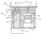
まず、溶湯Mを、注湯ロボット2によって湯だまり部11に充填する(図3)。また、溶湯Mを充填後、昇降用サーボ機構35により上下型ユニット10、30が閉じられる前に、直ちにプランジャーチップ用シリンダー16を駆動してプランジャーチップ13用のプランジャーチップ用シリンダー16を上昇移動させる(図4)。これにより、溶湯Mを流動させ、それより低温の下型入子17に接触し続けることによって凝固物が発生するのを防止する。
2 注湯ロボット
10 下型ユニット
11 湯だまり部
11a 上端開口部
12 形状加圧ピン
13 プランジャーチップ
14 形状加圧ピンロッド
15 形状加圧シリンダー
16 プランジャーチップ用シリンダー
17 下型入子
18 下型主型
19 下型受け台
20 下ダイベース
21 ガイドブッシュ
22 ピストンロッド
30 上型ユニット
31 上型入子
32 型締めラム加圧機構
33 押出ピン
34 押出ピン
35 昇降用サーボ機構
36 上ダイプレート
37 ノックアウトピン
38 上押出板
39 下押出板
40 上ダイベース
41 上型主型
42 ガイドピン
43 ガス抜き通路
44 ガイド孔
C キャビティ
C1 下型キャビティ
C2 上型キャビティ
D 形状加圧断層部貯留部
E 湯口ゲート
F1 ランナー残存材
F2 湯だまり残存材
M 溶湯
R ランナー
R1 下型ランナー
R2 上型ランナー
S 半製品
Claims (3)
- 成型用のキャビティを形成可能な下型ユニットと上型ユニットとを備える成型装置であって、
前記下型ユニットが、少なくとも、所定位置に保持された下ダイベースと、該下ダイベースに立設された下型受け台と、該下型受け台に載設し固定され、2つの上下方向の貫通孔を設けた下型主型と、該下型主型内に嵌設した、上面を開口部とする凹部及び下型主型と同軸の2つの貫通孔を設けた下型入子とを備え、該下型主型より下方に設置されたプランジャーチップ用シリンダーのピストンロッド上端に連結され、該下型主型及び下型入子に設けた上下方向の一方の貫通孔内を昇降するプランジャーチップの上面と、該下型入子に形成した上面が開口部を有する凹部とにより溶湯の湯だまり部を形成し、かつ、下ダイベースの下方に設けた形状加圧シリンダーの形状加圧ピンロッド上端に連結され、該下型主型及び下型入子に設けた他方の貫通孔内を昇降する形状加圧ピンの上部に下型キャビティを形成し、該下型キャビティと該湯だまり部とを連通させるように設けた下型ランナーと、下型キャビティの該湯だまり部には接しない側に平面視でキャビティを囲繞するように設けた略環状の湯口ゲートと、該湯口ゲートの下流側に設けた、押圧により流出した形状加圧断層部を貯留する平面視でキャビティを囲繞するように設けた略環状の貯留部とを含む構成からなり、
前記上型ユニットが、少なくとも、前記下型部の真上に昇降動自在に設けられ、下降移動して前記湯だまり部の上端開口部を閉鎖し、前記下型キャビティと対向状態で接合してキャビティを形成する上型キャビティを備えるとともに、前記下型ランナーと対向状態で接合してランナー部を形成する上型ランナーを備える上型入子と、該上型入子の上方に設けられた型締めラム加圧機構と、該上型入子の内部に設けられた上下方向の貫通孔に昇降自在に設けられ、下端面が該上型キャビティ又は該湯だまり部に当接する押出ピンと、上型ユニットを昇降動させる昇降用サーボ機構とを含む構成からなり、
該昇降用サーボ機構により上型ユニットが下降して下型ユニットと当接し、型締めラム加圧機構による加圧で上下型ユニットを乖離できないようにし、前記プランジャーチップによる上昇の圧力で溶湯をキャビティ内に侵入させてさらに溶湯に圧力を加えた状態で、前記キャビティ内に充満した溶湯に対して溶湯の凝固が始まったタイミングで形状加圧ピンが上昇して溶湯全域に亘り加圧することを特徴とする成型装置。 - 溶湯が湯だまり部に貯留された後に上型ユニットが昇降用サーボ機構で高速降下し上下型ユニットが当接して型締めされる過程の中で、前記型締め前の段階から前記プランジャーチップを上昇させて溶湯を流動させることを特徴とする請求項1に記載の成型装置。
- 前記キャビティ内に溶湯が充満した後に形状加圧ピンを上昇させて湯口ゲートの断面積及びランナーの断面積を小さくすることを特徴とする請求項1又は2に記載の成型装置。
Priority Applications (1)
| Application Number | Priority Date | Filing Date | Title |
|---|---|---|---|
| JP2012224690A JP6075533B2 (ja) | 2012-10-10 | 2012-10-10 | 成型装置 |
Applications Claiming Priority (1)
| Application Number | Priority Date | Filing Date | Title |
|---|---|---|---|
| JP2012224690A JP6075533B2 (ja) | 2012-10-10 | 2012-10-10 | 成型装置 |
Publications (2)
| Publication Number | Publication Date |
|---|---|
| JP2014076461A JP2014076461A (ja) | 2014-05-01 |
| JP6075533B2 true JP6075533B2 (ja) | 2017-02-08 |
Family
ID=50782241
Family Applications (1)
| Application Number | Title | Priority Date | Filing Date |
|---|---|---|---|
| JP2012224690A Active JP6075533B2 (ja) | 2012-10-10 | 2012-10-10 | 成型装置 |
Country Status (1)
| Country | Link |
|---|---|
| JP (1) | JP6075533B2 (ja) |
Families Citing this family (2)
| Publication number | Priority date | Publication date | Assignee | Title |
|---|---|---|---|---|
| CN114130989A (zh) * | 2021-11-10 | 2022-03-04 | 宁波海瑞时新材料有限公司 | 一种挤压铸造模具及工艺方法 |
| CN118720058B (zh) * | 2024-09-03 | 2025-01-14 | 大连远景铸造有限公司 | 一种冒口加压装置及其加压方法 |
Family Cites Families (9)
| Publication number | Priority date | Publication date | Assignee | Title |
|---|---|---|---|---|
| JPS5954157U (ja) * | 1982-10-02 | 1984-04-09 | 株式会社豊田自動織機製作所 | 溶湯鍛造型装置 |
| JPS60174236A (ja) * | 1984-02-21 | 1985-09-07 | Toyota Central Res & Dev Lab Inc | 繊維強化金属鋳物用鋳型およびこの鋳型を用いた鋳造方法 |
| JPS6149764A (ja) * | 1984-08-14 | 1986-03-11 | Nissan Motor Co Ltd | 溶湯鍛造法およびその装置 |
| IT1231211B (it) * | 1989-08-24 | 1991-11-23 | Tva Holding | Procedimento per la colata a pressione controllata di metalli fusi, particolarmente leghe leggere di alluminio e di magnesio, e apparecchiatura per la sua esecuzione |
| JPH06210426A (ja) * | 1992-03-04 | 1994-08-02 | Mitsubishi Electric Corp | 鋳物の製造方法及び製造装置 |
| JPH10216920A (ja) * | 1997-02-07 | 1998-08-18 | Olympus Optical Co Ltd | 非晶質合金の成形装置及び成形方法 |
| JPH11156513A (ja) * | 1997-11-28 | 1999-06-15 | Asahi Tec Corp | 金属部材の鋳造方法及びこの方法に用いる鋳造用金型 |
| JP2005305466A (ja) * | 2004-04-19 | 2005-11-04 | Art Metal Mfg Co Ltd | 溶湯鍛造装置および溶湯鍛造法 |
| JP2009208091A (ja) * | 2008-02-29 | 2009-09-17 | Kimura Kogyo:Kk | 成型装置 |
-
2012
- 2012-10-10 JP JP2012224690A patent/JP6075533B2/ja active Active
Also Published As
| Publication number | Publication date |
|---|---|
| JP2014076461A (ja) | 2014-05-01 |
Similar Documents
| Publication | Publication Date | Title |
|---|---|---|
| CN101274361B (zh) | 低速真空压挤铸造工艺 | |
| CN206425523U (zh) | 一种容易脱模的铸件模具 | |
| JP2000135551A (ja) | 無孔質ダイキャスト装置 | |
| JP6075533B2 (ja) | 成型装置 | |
| KR100537493B1 (ko) | 가압식 다이캐스팅 장치 및 이를 이용한 다이캐스팅 방법 | |
| WO2018053939A1 (zh) | 铸件的挤压铸造方法 | |
| JP2015039723A (ja) | 車輪または車輪中心部の鋳造方法 | |
| CN103433460A (zh) | 一种用于销孔处设有凹陷平台的支架的模具 | |
| CN203426407U (zh) | 轿车轮毂压铸模具 | |
| JP2005305466A (ja) | 溶湯鍛造装置および溶湯鍛造法 | |
| CN102019400B (zh) | 利用挤压铸造工艺制造发动机缸套类铸件的方法及模具 | |
| KR100832248B1 (ko) | 알루미늄 휠 주조장치 | |
| CN209998344U (zh) | 一种振动挤压轮毂铸造模具 | |
| US7823622B2 (en) | Ejection and stamping device | |
| CN103286296A (zh) | 一种减震器内芯压铸模具 | |
| JP2014076450A (ja) | ナックル用重力鋳造装置及び重力鋳造法 | |
| CN203737980U (zh) | 一种用于制造多个减震部件本体的模具 | |
| CN202316963U (zh) | 雷诺l38车型发动机悬挂支架压铸模具动模结构 | |
| CN102825241B (zh) | 带局部加压的金属型低压铸造结构 | |
| JP3339290B2 (ja) | 鋳物の製造装置 | |
| RU2631785C2 (ru) | Способ изготовления металлополимерных формообразующих поверхностей матриц и пуансонов пресс-форм | |
| JP2009262196A (ja) | 鋳造方法および鋳型 | |
| JPH0481256A (ja) | ダイカスト鋳造装置 | |
| JPS5855859B2 (ja) | 横型締,竪鋳込型ダイカスト法および装置 | |
| CN105964978A (zh) | 一种挤压铸造模具 |
Legal Events
| Date | Code | Title | Description |
|---|---|---|---|
| A621 | Written request for application examination |
Free format text: JAPANESE INTERMEDIATE CODE: A621 Effective date: 20150915 |
|
| A977 | Report on retrieval |
Free format text: JAPANESE INTERMEDIATE CODE: A971007 Effective date: 20160815 |
|
| A131 | Notification of reasons for refusal |
Free format text: JAPANESE INTERMEDIATE CODE: A131 Effective date: 20160913 |
|
| A521 | Request for written amendment filed |
Free format text: JAPANESE INTERMEDIATE CODE: A523 Effective date: 20161114 |
|
| A521 | Request for written amendment filed |
Free format text: JAPANESE INTERMEDIATE CODE: A821 Effective date: 20161114 |
|
| TRDD | Decision of grant or rejection written | ||
| A01 | Written decision to grant a patent or to grant a registration (utility model) |
Free format text: JAPANESE INTERMEDIATE CODE: A01 Effective date: 20161220 |
|
| A61 | First payment of annual fees (during grant procedure) |
Free format text: JAPANESE INTERMEDIATE CODE: A61 Effective date: 20161227 |
|
| R150 | Certificate of patent or registration of utility model |
Ref document number: 6075533 Country of ref document: JP Free format text: JAPANESE INTERMEDIATE CODE: R150 |
|
| R250 | Receipt of annual fees |
Free format text: JAPANESE INTERMEDIATE CODE: R250 |
|
| R250 | Receipt of annual fees |
Free format text: JAPANESE INTERMEDIATE CODE: R250 |
|
| R250 | Receipt of annual fees |
Free format text: JAPANESE INTERMEDIATE CODE: R250 |