JP6012569B2 - Power window device for vehicle - Google Patents
Power window device for vehicle Download PDFInfo
- Publication number
- JP6012569B2 JP6012569B2 JP2013187880A JP2013187880A JP6012569B2 JP 6012569 B2 JP6012569 B2 JP 6012569B2 JP 2013187880 A JP2013187880 A JP 2013187880A JP 2013187880 A JP2013187880 A JP 2013187880A JP 6012569 B2 JP6012569 B2 JP 6012569B2
- Authority
- JP
- Japan
- Prior art keywords
- seat
- switch
- window
- motor
- relay
- Prior art date
- Legal status (The legal status is an assumption and is not a legal conclusion. Google has not performed a legal analysis and makes no representation as to the accuracy of the status listed.)
- Active
Links
- 238000001514 detection method Methods 0.000 claims description 61
- 230000006870 function Effects 0.000 description 7
- 238000004891 communication Methods 0.000 description 3
- 238000000034 method Methods 0.000 description 3
- 238000012544 monitoring process Methods 0.000 description 3
- 238000006243 chemical reaction Methods 0.000 description 2
- 230000005611 electricity Effects 0.000 description 2
- 230000007423 decrease Effects 0.000 description 1
- 238000010586 diagram Methods 0.000 description 1
Images


Classifications
-
- E—FIXED CONSTRUCTIONS
- E05—LOCKS; KEYS; WINDOW OR DOOR FITTINGS; SAFES
- E05F—DEVICES FOR MOVING WINGS INTO OPEN OR CLOSED POSITION; CHECKS FOR WINGS; WING FITTINGS NOT OTHERWISE PROVIDED FOR, CONCERNED WITH THE FUNCTIONING OF THE WING
- E05F15/00—Power-operated mechanisms for wings
- E05F15/60—Power-operated mechanisms for wings using electrical actuators
- E05F15/603—Power-operated mechanisms for wings using electrical actuators using rotary electromotors
- E05F15/665—Power-operated mechanisms for wings using electrical actuators using rotary electromotors for vertically-sliding wings
- E05F15/689—Power-operated mechanisms for wings using electrical actuators using rotary electromotors for vertically-sliding wings specially adapted for vehicle windows
- E05F15/695—Control circuits therefor
Landscapes
- Power-Operated Mechanisms For Wings (AREA)
- Window Of Vehicle (AREA)
Description
本発明は、車両の窓を開閉するためのパワーウインドウ装置に関し、特に、運転席でのスイッチ操作により、他席を含む全席の窓を開閉できるパワーウインドウ装置に関する。 The present invention relates to a power window device for opening and closing a window of a vehicle, and more particularly to a power window device capable of opening and closing windows of all seats including other seats by a switch operation at a driver's seat.
電動モータにより車両の窓を開閉するパワーウインドウ装置においては、操作スイッチの操作状況に応じて、モータを正転方向または逆転方向へ回転させ、窓の開閉を行うようにしている。例えば、操作スイッチをUP側(窓閉側)へ操作すると、モータが正転方向に駆動されて窓が閉じ、操作スイッチをDOWN側(窓開側)へ操作すると、モータが逆転方向に駆動されて窓が開く。モータの正転と逆転の制御は、操作スイッチからの信号に基づき、モータ駆動回路においてモータに流れる電流の方向を切り替えることにより行う。 In a power window device that opens and closes a vehicle window with an electric motor, the motor is rotated in the normal rotation direction or the reverse rotation direction in accordance with the operation state of the operation switch to open and close the window. For example, when the operation switch is operated to the UP side (window closing side), the motor is driven in the forward rotation direction and the window is closed, and when the operation switch is operated to the DOWN side (window opening side), the motor is driven in the reverse rotation direction. Window opens. Control of forward and reverse rotation of the motor is performed by switching the direction of the current flowing through the motor in the motor drive circuit based on the signal from the operation switch.
一般に、自動車においては、運転席と、それ以外の座席(助手席、左後部席、右後部席など)のそれぞれに操作スイッチが備わっている。運転席に備わる操作スイッチは、運転席の窓の開閉を操作する運転席スイッチのほかに、助手席などの他席の窓の開閉を遠隔操作する他席スイッチを含んでいる。他席に備わる操作スイッチは、その席の窓の開閉のみを操作するものである。そして、これらのスイッチの操作に基づいて、各座席の窓の開閉を制御する制御部が設けられる。 Generally, in an automobile, an operation switch is provided in each of a driver seat and other seats (a passenger seat, a left rear seat, a right rear seat, etc.). The operation switch provided in the driver's seat includes, in addition to the driver's seat switch for operating the opening / closing of the driver's seat window, the other seat switch for remotely operating the opening / closing of the window of the other seat such as the passenger seat. The operation switch provided in the other seat operates only to open and close the window of the seat. And based on operation of these switches, the control part which controls opening and closing of the window of each seat is provided.
特許文献1には、運転席に備わる操作スイッチと他席に備わる操作スイッチのそれぞれに対して制御部が設けられ、運転席の制御部と他席の制御部とがシリアル通信線で接続されたパワーウインドウ装置が開示されている。この装置では、運転席の操作スイッチで他席の窓の開閉操作が行われた場合は、シリアル通信線を通して、運転席の制御部から該当する席の制御部へ通信が行われ、その席の制御部が当該席の窓開閉用モータを駆動する。
In
特許文献2には、運転席に備わる操作スイッチと他席に備わる操作スイッチに対して、1つの制御部が設けられたパワーウインドウ装置が開示されている。この装置では、1つの制御部が、運転席の操作スイッチや他席の操作スイッチからの入力を受けて、各席の窓開閉用モータを制御する。
特許文献3には、操作スイッチおよび制御部を含む運転席ユニットと、操作スイッチおよびリレーを含む他席ユニットとを、単一の信号ラインで接続したパワーウインドウ装置が開示されている。この装置では、運転席ユニットにおける他席の窓の開閉操作に応じて、他席ユニットの操作スイッチおよびリレーの各接点を用いて、他席の窓開閉用モータに流れる電流の方向を切り替える。
このようなパワーウインドウ装置において、スイッチの操作による窓の開閉動作には、マニュアル動作とオート動作がある。マニュアル動作の場合は、スイッチをマニュアル開位置まで操作すると、窓の開動作が開始され、スイッチを操作している間だけ開動作が継続される。そして、スイッチの操作を解除すると窓の開動作が停止する。また、スイッチをマニュアル閉位置まで操作すると、窓の閉動作が開始され、スイッチを操作している間だけ閉動作が継続される。そして、スイッチの操作を解除すると窓の閉動作が停止する。 In such a power window device, there are a manual operation and an automatic operation for opening and closing the window by operating the switch. In the case of manual operation, when the switch is operated to the manual opening position, the opening operation of the window is started, and the opening operation is continued only while the switch is operated. When the operation of the switch is released, the window opening operation is stopped. Further, when the switch is operated to the manual closing position, the window closing operation is started, and the closing operation is continued only while the switch is operated. When the switch operation is released, the window closing operation is stopped.
一方、オート動作の場合は、スイッチをマニュアル開位置からオート開位置までさらに操作すると、オート開動作へ移行し、スイッチの操作を解除しても、窓の開動作が継続される。そして、窓が全開状態になると、窓の開動作が停止する。また、スイッチをマニュアル閉位置からオート閉位置までさらに操作すると、オート閉動作へ移行し、スイッチの操作を解除しても、窓の閉動作が継続される。そして、窓が全閉状態になると、窓の閉動作が停止する。 On the other hand, in the case of the automatic operation, if the switch is further operated from the manual opening position to the automatic opening position, the operation moves to the automatic opening operation, and the opening operation of the window is continued even if the switch operation is canceled. When the window is fully opened, the opening operation of the window is stopped. Further, when the switch is further operated from the manual closing position to the automatic closing position, the operation shifts to the automatic closing operation, and the window closing operation is continued even when the operation of the switch is released. When the window is fully closed, the window closing operation is stopped.
従来のパワーウインドウ装置では、運転席以外の他席に設けられる操作スイッチが、マニュアル動作の機能のみを有し、オート動作の機能を有していない場合は、他席での操作によって、他席の窓をオート動作で開閉することはできなかった。 In the conventional power window device, if the operation switch provided in a seat other than the driver's seat has only a manual operation function and does not have an automatic operation function, the other seat can be operated by operating the other seat. The window could not be opened and closed automatically.
一方、運転席以外の他席に設けられる操作スイッチが、オート動作の機能を有している場合は、他席での操作によって、他席の窓をオート動作で開閉することができる。しかし、オート動作の機能を有するスイッチは、マニュアル開、マニュアル閉、オート開、オート閉の各位置へ多段階に切替可能であることが必要なため、スイッチの構成が複雑となる。 On the other hand, when an operation switch provided in a seat other than the driver's seat has an automatic operation function, the window of the other seat can be opened and closed by the operation in the other seat. However, since a switch having an automatic operation function needs to be switchable in multiple stages to each of manual open, manual close, auto open, and auto close positions, the switch configuration becomes complicated.
本発明の課題は、他席に設けられる操作スイッチの構成を簡略化しつつ、他席での操作により他席の窓をオート動作で開閉することが可能なパワーウインドウ装置を実現することにある。 An object of the present invention is to realize a power window device capable of automatically opening and closing a window of another seat by an operation on the other seat while simplifying a configuration of an operation switch provided in the other seat.
本発明に係る車両用パワーウインドウ装置は、車両の運転席に設けられる運転席ユニットと、運転席以外の他席に設けられ、運転席ユニットと電気的に接続される、他席の窓を開閉するための第1他席スイッチとを含む。運転席ユニットは、運転席の窓を開閉するための運転席スイッチと、他席の窓を開閉するための第2他席スイッチと、運転席スイッチおよび第2他席スイッチの操作に基づき、運転席の窓を開閉する運転席モータおよび他席の窓を開閉する他席モータを制御する制御部とを有する。運転席ユニットは、第1他席スイッチの所定の操作に基づいて動作する切替回路を備えている。第1他席スイッチは、他席の窓をマニュアル動作で開閉するためのマニュアルスイッチであって、他席モータの一端を電源または切替回路に接続するための第1スイッチと、他席モータの他端を電源または切替回路に接続するための第2スイッチとを有している。さらに、他席モータの一端もしくは他端の電圧を検出する電圧検出回路、および/または他席モータに流れる電流を検出する電流検出回路からなる検出手段が設けられる。制御部は、第2他席スイッチが操作されない状態で、検出手段で検出された電圧または電流に基づき、第1他席スイッチが一定時間を超えて延長操作されたことを検知した場合に、切替回路を駆動する。そして、制御部は、第1他席スイッチの延長操作が解除された後、電源から、切替回路および第1他席スイッチを介して、他席モータへ通電することにより、他席の窓をオート動作で全開または全閉させる。 A power window device for a vehicle according to the present invention opens and closes a driver's seat unit provided in a driver's seat of a vehicle and a window of another seat provided in a seat other than the driver's seat and electrically connected to the driver's seat unit. And a first other seat switch for the purpose. The driver's seat unit operates based on the operation of the driver's seat switch for opening / closing the driver's seat window, the second other seat switch for opening / closing the window of the other seat, and the driver's seat switch and the second other seat switch. A driver seat motor that opens and closes the seat window, and a controller that controls the other seat motor that opens and closes the window of the other seat. The driver seat unit includes a switching circuit that operates based on a predetermined operation of the first other seat switch. The first other seat switch is a manual switch for manually opening and closing the windows of the other seats, and includes a first switch for connecting one end of the other seat motor to a power source or a switching circuit, and other seat motors. And a second switch for connecting the end to a power source or a switching circuit. Furthermore, a detection means is provided that includes a voltage detection circuit that detects a voltage at one end or the other end of the other-seat motor and / or a current detection circuit that detects a current flowing through the other-seat motor. The control unit switches when the second other seat switch is not operated and detects that the first other seat switch is extended over a predetermined time based on the voltage or current detected by the detecting means. Drive the circuit. Then, after the extension operation of the first other seat switch is released, the control unit automatically turns on the other seat window from the power source through the switching circuit and the first other seat switch. Fully open or fully closed by operation.
このような構成によると、マニュアルスイッチからなる第1他席スイッチが一定時間を超えて操作され続けると、切替回路が駆動されてオート動作へ移行し、切替回路と第1他席スイッチを介して、他席モータへの通電が行われる。したがって、その後第1他席スイッチの操作を解除しても、他席モータは回転を継続するので、マニュアルスイッチを用いて、オート閉またはオート開の動作を行わせることができる。このため、第1他席スイッチの構成を簡略化しつつ、第1他席スイッチにより他席の窓をオート動作で開閉することができる。 According to such a configuration, when the first other-seat switch composed of the manual switch continues to be operated for a certain period of time, the switching circuit is driven to shift to the automatic operation, and the switching circuit and the first other-seat switch are passed through. The other seat motor is energized. Therefore, even if the operation of the first other-seat switch is subsequently released, the other-seat motor continues to rotate, so that the auto-close or auto-open operation can be performed using the manual switch. For this reason, the window of the other seat can be opened and closed by the automatic operation by the first other seat switch while simplifying the configuration of the first other seat switch.
本発明の好ましい実施形態では、制御部は、以下のような制御を行う。第1他席スイッチの延長操作が解除された後、他席の窓がオート閉動作で閉じている途中で、第1他席スイッチが窓開側に操作された場合は、オート閉動作を解除して他席モータを停止させる。第1他席スイッチの延長操作が解除された後、他席の窓がオート開動作で開いている途中で、第1他席スイッチが窓閉側に操作された場合は、オート開動作を解除して他席モータを停止させる。 In a preferred embodiment of the present invention, the control unit performs the following control. After the extension operation of the first other seat switch is canceled, if the first other seat switch is operated to open the window while the other seat window is closed by the auto close operation, the auto close operation is canceled. Then stop the other seat motor. After the extension operation of the first other seat switch is canceled, if the first other seat switch is operated to the window closing side while the other seat window is being opened by the automatic opening operation, the auto opening operation is canceled. Then stop the other seat motor.
本発明では、切替回路は、窓閉用の第1リレーと、窓開用の第2リレーとを有していてもよい。この場合、第1スイッチは、第1他席スイッチを窓閉側に操作したときに、電源側に切り替わり、第2スイッチは、第1他席スイッチを窓開側に操作したときに、電源側に切り替わる。そして、第1スイッチが電源側に切り替わった状態で、第1他席スイッチが延長操作された場合は、第1リレーが電源側に切り替わり、第1他席スイッチの延長操作が解除された後、電源から第1リレー、第1スイッチ、他席モータ、第2スイッチ、第2リレー、およびグランドへ至る電流経路が形成される。また、第2スイッチが電源側に切り替わった状態で、第1他席スイッチが延長操作された場合は、第2リレーが電源側に切り替わり、第1他席スイッチの延長操作が解除された後、電源から第2リレー、第2スイッチ、他席モータ、第1スイッチ、第1リレー、およびグランドへ至る電流経路が形成される。 In the present invention, the switching circuit may include a first relay for closing a window and a second relay for opening a window. In this case, the first switch is switched to the power source side when the first other seat switch is operated to the window closing side, and the second switch is the power source side when the first other seat switch is operated to the window opening side. Switch to Then, when the first other seat switch is extended in the state where the first switch is switched to the power source side, the first relay is switched to the power source side, and the extension operation of the first other seat switch is released, A current path is formed from the power source to the first relay, the first switch, the other seat motor, the second switch, the second relay, and the ground. In addition, when the first other seat switch is extended while the second switch is switched to the power source side, the second relay is switched to the power source side, and after the extension operation of the first other seat switch is released, A current path is formed from the power source to the second relay, the second switch, the other seat motor, the first switch, the first relay, and the ground.
本発明の好ましい実施形態では、制御部は、第1スイッチが電源側に切り替わったときに電圧検出回路で検出される電圧と、第2スイッチが電源側に切り替わったときに電圧検出回路で検出される電圧とに基づいて、第1スイッチと第2スイッチのいずれが電源側に切り替わったかを判定する。そして、制御部は、第1スイッチが電源側に切り替わったと判定した場合は、第1リレーを電源側に切り替え、第2スイッチが電源側に切り替わったと判定した場合は、第2リレーを電源側に切り替える。 In a preferred embodiment of the present invention, the control unit detects the voltage detected by the voltage detection circuit when the first switch is switched to the power supply side, and the voltage detection circuit detects when the second switch is switched to the power supply side. It is determined which of the first switch and the second switch is switched to the power source side based on the voltage to be switched. When the control unit determines that the first switch is switched to the power supply side, the control unit switches the first relay to the power supply side. When the control unit determines that the second switch is switched to the power supply side, the second relay is switched to the power supply side. Switch.
本発明において、制御部は、第1他席スイッチが所定時間を超えて延長操作されたことを検知することに代えて、第1他席スイッチが所定時間内に複数回連続して操作されたことを検知してもよい。 In the present invention, instead of detecting that the first other-seat switch has been extended for more than a predetermined time, the control unit has been operated continuously for a plurality of times within the predetermined time. You may detect that.
本発明によれば、他席に設けられる操作スイッチの構成を簡略化しつつ、他席での操作により他席の窓をオート動作で開閉することが可能なパワーウインドウ装置を提供することができる。 ADVANTAGE OF THE INVENTION According to this invention, the power window apparatus which can open and close the window of an other seat by auto operation | movement by the operation in an other seat can be provided, simplifying the structure of the operation switch provided in an other seat.
以下、本発明に係る車両用パワーウインドウ装置(以下、単に「パワーウインドウ装置」という。)の実施形態につき、図面を参照しながら説明する。各図において、同一の部分または対応する部分には、同一の符号を付してある。 Hereinafter, an embodiment of a power window device for a vehicle according to the present invention (hereinafter simply referred to as “power window device”) will be described with reference to the drawings. In each drawing, the same reference numerals are given to the same or corresponding parts.
最初に、パワーウインドウ装置の概略構成につき、図1を参照しながら説明する。図1において、パワーウインドウ装置100は、運転席ユニット1と、他席スイッチ2とから構成され、運転席の窓を開閉する運転席モータ3と、運転席以外の他席の窓を開閉する他席モータ4を制御する。
First, a schematic configuration of the power window device will be described with reference to FIG. In FIG. 1, a
運転席ユニット1は、車両の運転席に設けられており、制御部10、運転席スイッチ11、他席スイッチ12、他席オート動作用リレー13、電圧検出回路14、および電流検出回路15を有している。
The driver's
制御部10は、CPUやメモリなどから構成されており、パワーウインドウ装置100の動作を制御する。運転席スイッチ11は、運転席モータ3により運転席の窓を開閉するためのスイッチである。
The
他席スイッチ12は、他席モータ4により運転席以外の他席の窓を開閉するためのスイッチであって、助手席スイッチ121、右後部席スイッチ122、および左後部席スイッチ123からなる。助手席スイッチ121は、運転席において助手席の窓の開閉を操作するためのスイッチである。右後部席スイッチ122は、運転席において右後部席の窓の開閉を操作するためのスイッチである。左後部席スイッチ123は、運転席において左後部席の窓の開閉を操作するためのスイッチである。運転席スイッチ11と他席スイッチ12は、共に、マニュアル動作とオート動作の各機能を備えている。
The
他席オート動作用リレー13は、他席スイッチ2で所定の操作が行われた場合に動作して、他席の窓の開閉動作をマニュアル動作からオート動作へ切り替えるためのリレーであって、助手席オート動作用リレー131、右後部席オート動作用リレー132、および左後部席オート動作用リレー133からなる。電圧検出回路14と電流検出回路15については、後で説明する。
The other-seat
他席スイッチ2は、運転席以外の他席に設けられ、運転席ユニットと電気的に接続されている。この他席スイッチ2は、他席での操作により、当該他席の窓を開閉するためのスイッチであって、助手席スイッチ21、右後部席スイッチ22、および左後部席スイッチ23からなる。
The
助手席スイッチ21は、助手席において助手席の窓の開閉を操作するためのスイッチである。右後部席スイッチ22は、右後部席において右後部席の窓の開閉を操作するためのスイッチである。左後部席スイッチ23は、左後部席において左後部席の窓の開閉を操作するためのスイッチである。これらの他席スイッチ21〜23は、他席の窓をマニュアル動作で開閉するためのマニュアルスイッチであって、スイッチが操作されている間だけ接点が切り替わる、いわゆるモーメンタリ式スイッチからなる。他席スイッチ21〜23には、オート動作で他席の窓を自動的に全開または全閉させる機能はない。
The
運転席モータ3は、運転席スイッチ11の操作に基づいて、運転席の窓の開閉を行うモータであって、運転席ユニット1と電気的に接続されている。他席モータ4は、運転席に設けられた他席スイッチ12または他席に設けられた他席スイッチ2の操作に基づいて、他席の窓の開閉を行うモータであって、助手席モータ41、右後部席モータ42、および左後部席モータ43からなる。
The
助手席モータ41は、助手席の窓の開閉を行うモータであって、助手席スイッチ21および運転席ユニット1と電気的に接続されている。より具体的には、助手席モータ41の一端(図1で下側)は、運転席ユニット1と電気的に接続されているとともに、運転席ユニット1を経由して、助手席スイッチ21と電気的に接続されている。また、助手席モータ41の他端(図1で上側)は、助手席スイッチ21と電気的に接続されている。
The
右後部席モータ42は、右後部席の窓の開閉を行うモータであって、右後部席スイッチ22および運転席ユニット1と電気的に接続されている。より具体的には、右後部席モータ42の一端(図1で下側)は、運転席ユニット1と電気的に接続されているとともに、運転席ユニット1を経由して、右後部席スイッチ22と電気的に接続されている。また、右後部席モータ42の他端(図1で上側)は、右後部席スイッチ22と電気的に接続されている。
The right
左後部席モータ43は、左後部席の窓の開閉を行うモータであって、左後部席スイッチ23および運転席ユニット1と電気的に接続されている。より具体的には、左後部席モータ43の一端(図1で下側)は、運転席ユニット1と電気的に接続されているとともに、運転席ユニット1を経由して、左後部席スイッチ23と電気的に接続されている。また、左後部席モータ43の他端(図1で上側)は、左後部席スイッチ23と電気的に接続されている。
The left
運転席ユニット1の電圧検出回路14は、助手席モータ41、右後部席モータ42、および左後部席モータ43の各モータの一端の電圧を検出する回路である。また、運転席ユニット1の電流検出回路15は、運転席モータ3、助手席モータ41、右後部席モータ42、および左後部席モータ43の各モータに流れるモータ電流を検出する。
The
以上の構成において、他席に設けられる他席スイッチ2は、本発明における「第1他席スイッチ」の一例であり、運転席に設けられる他席スイッチ12は、本発明における「第2他席スイッチ」の一例である。また、他席オート動作用リレー13は、本発明における「切替回路」の一例である。また、電圧検出回路14と電流検出回路15は、本発明における「検出手段」の一例である。
In the above configuration, the
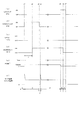
次に、運転席ユニット1と他席スイッチ2の具体的構成を、図2を参照しながら説明する。図2では、運転席ユニット1において、図1の運転席スイッチ11および他席スイッチ12の図示を省略してある。また、図1の他席スイッチ2として、助手席スイッチ21のみを図示し、右後部席スイッチ22と左後部席スイッチ23の図示を省略してある。これに対応して、図2では、他席オート動作用リレー13として、助手席オート動作用リレー131のみを図示し、右後部席オート動作用リレー132と左後部席オート動作用リレー133の図示を省略してある。また、他席モータ4として、助手席モータ41のみを図示し、右後部席モータ42と左後部席モータ43の図示を省略してある。
Next, specific configurations of the driver's
運転席ユニット1において、助手席オート動作用リレー131は、2つのリレー131u、131dからなる。リレー131uは、助手席の窓をオート閉動作で閉じる場合に動作する窓閉用のリレーであって、コイルXuと、接点Yuとを備えている。リレー131dは、助手席の窓をオート開動作で開く場合に動作する窓開用のリレーであって、コイルXdと、接点Ydとを備えている。以下、リレー131uを「UPリレー」といい、リレー131dを「DOWNリレー」という。
In the driver's
UPリレー131uにおいて、コイルXuの一端は、電源Bに接続されており、コイルXuの他端は、制御部10に接続されている。接点Yuは、コイルXuに通電されていない状態では、常閉端子b側(グランド側)に切り替わっており、コイルXuに通電されると、常開端子a側(電源側)に切り替わる。常開端子aは、電源Bに接続されているとともに、DOWNリレー131dの常開端子aに接続されている。常閉端子bは、後述するシャント抵抗Rsを介して、グランドGに接地されているとともに、DOWNリレー131dの常閉端子bに接続されている。接点Yuの共通端子cは、運転席ユニット1の端子T1に接続されている。
In the
DOWNリレー131dにおいて、コイルXdの一端は、電源Bに接続されており、コイルXdの他端は、制御部10に接続されている。接点Ydは、コイルXdに通電されていない状態では、常閉端子b側(グランド側)に切り替わっており、コイルXdに通電されると、常開端子a側(電源側)に切り替わる。常開端子aは、電源Bに接続されているとともに、UPリレー131uの常開端子aに接続されている。常閉端子bは、後述するシャント抵抗Rsを介して、グランドGに接地されているとともに、UPリレー131uの常閉端子bに接続されている。接点Ydの共通端子cは、運転席ユニット1の端子T2に接続されている。
In the
助手席スイッチ21は、2つのスイッチ21u、21dからなる。スイッチ21uは、助手席の窓を閉じる場合に操作する窓閉用のスイッチである。スイッチ21dは、助手席の窓を開く場合に操作する窓開用のスイッチである。この助手席スイッチ21は、助手席の窓をマニュアル動作で開閉するためのマニュアルスイッチであって、スイッチ21u、21dが操作されている間だけ接点が切り替わる、いわゆるモーメンタリ式スイッチからなる。助手席スイッチ21には、オート動作で助手席の窓を全開または全閉させる機能はない。以下、スイッチ21uを「UPスイッチ」といい、スイッチ21dを「DOWNスイッチ」という。
The
UPスイッチ21uは、常開端子a側(電源側)と常閉端子b側(グランド側)に切り替わる。常開端子aは、電源Bに接続されているとともに、DOWNスイッチ21dの常開端子aに接続されている。常閉端子bは、助手席スイッチ21の端子T5に接続されており、共通端子cは、助手席スイッチ21の端子T7に接続されている。端子T5は、配線L1を介して運転席ユニット1の端子T1に接続されている。これにより、UPスイッチ21uの常閉端子bは、端子T5、配線L1、端子T1、UPリレー131uの常閉端子b、およびシャント抵抗Rsを介して、グランドGに接地されている。
The
DOWNスイッチ21dも、常開端子a側(電源側)と常閉端子b側(グランド側)に切り替わる。常開端子aは、電源Bに接続されているとともに、UPスイッチ21uの常開端子aに接続されている。常閉端子bは、助手席スイッチ21の端子T6に接続されており、共通端子cは、助手席スイッチ21の端子T8に接続されている。端子T6は、配線L2を介して運転席ユニット1の端子T2に接続されている。これにより、DOWNスイッチ21dの常閉端子bは、端子T6、配線L2、端子T2、DOWNリレー131dの常閉端子b、およびシャント抵抗Rsを介して、グランドGに接地されている。
The
助手席スイッチ21の端子T7は、配線L3により運転席ユニット1の端子T3に接続されている。助手席スイッチ21の端子T8と、運転席ユニット1の端子T4との間には、助手席モータ41が設けられている。助手席モータ41の一端は、配線L4により、運転席ユニット1の端子T4に接続されている。助手席モータ41の他端は、配線L5により、助手席スイッチ21の端子T8に接続されている。
A terminal T7 of the
運転席ユニット1において、端子T3は、電圧検出回路14に接続されているとともに、端子T4に接続されている。したがって、助手席モータ41の一端は、配線L4および端子T4を介して、電圧検出回路14に接続されている。
In the driver's
電圧検出回路14は、端子T3、T4と制御部10との間に設けられており、抵抗R1および抵抗R2から構成される。抵抗R1の一端は、抵抗R2の一端に接続されているとともに、制御部10に接続されている。抵抗R1の他端は、端子T3および端子T4に接続されており、抵抗R2の他端は、グランドGに接地されている。
The
シャント抵抗Rsは、助手席モータ41に流れるモータ電流を検出するための抵抗である。シャント抵抗Rsの一端は、UPリレー131uおよびDOWNリレー131dのそれぞれの常閉端子bに接続されている。シャント抵抗Rsの他端は、グランドGに接地されている。電流検出回路15の入力側は、シャント抵抗Rsの両端に接続されている。電流検出回路15の出力側は、制御部10に接続されている。制御部10には、電流検出回路15の出力に基づいて、窓に異物が挟み込まれたことを検出する、挟込検出部10aが備わっている。
The shunt resistor Rs is a resistor for detecting the motor current flowing through the
以上の構成において、UPスイッチ21uは、本発明における「第1スイッチ」の一例であり、DOWNスイッチ21dは、本発明における「第2スイッチ」の一例である。また、UPリレー131uは、本発明における「第1リレー」の一例であり、DOWNリレー131dは、本発明における「第2リレー」の一例である。
In the above configuration, the
次に、上述したパワーウインドウ装置100の動作について説明する。なお、運転席ユニット1の運転席スイッチ11を操作して運転席の窓を開閉する動作や、運転席ユニット1の他席スイッチ12を操作して他席の窓を開閉する動作については、従来と同じであるので、説明を省略する。
Next, the operation of the
ここでは、他席スイッチ2を代表して、助手席スイッチ21が操作された場合の動作について述べる。以下、助手席スイッチ21を窓閉側に操作して窓を閉じる操作(窓閉操作)を「UP操作」、助手席スイッチ21を窓開側に操作して窓を開く操作(窓開操作)を「DOWN操作」という。また、マニュアル動作で窓が閉じる動作(マニュアル閉動作)を「マニュアルUP動作」、マニュアル動作で窓が開く動作(マニュアル開動作)を「マニュアルDOWN動作」、オート動作で窓が閉じる動作(オート閉動作)を「オートUP動作」、オート動作で窓が開く動作(オート開動作)を「オートDOWN動作」という。
Here, the operation when the
(1)通常状態
運転席ユニット1の助手席スイッチ121と、他席スイッチ2の助手席スイッチ21がいずれも操作されていない場合は、パワーウインドウ装置100は図2の状態にある。この状態では、電源Bから助手席モータ41への電流経路が形成されないので、助手席モータ41は通電されず停止している。
(1) Normal State When neither the
(2)窓を閉じる場合
<マニュアルUP動作>
図3は、運転席ユニット1の助手席スイッチ121が操作されない状態で、他席スイッチ2の助手席スイッチ21がUP操作された場合の電流経路を示している。助手席スイッチ21のUP操作により、窓閉用のUPスイッチ21uが、常開端子a側に切り替わる。すると、破線矢印で示すように、電源B→UPスイッチ21u→端子T7→配線L3→端子T3→端子T4→配線L4→助手席モータ41→配線L5→端子T8→DOWNスイッチ21d→端子T6→配線L2→端子T2→DOWNリレー131dの接点Yd→シャント抵抗Rs→グランドGへ至る電流経路が形成される。
(2) When closing the window <Manual UP operation>
FIG. 3 shows a current path when the
このため、助手席モータ41には、当該モータを正転させる方向の電流が流れる。その結果、助手席モータ41は正転方向に回転し、これと連動して、窓が閉じてゆく。そして、一定時間が経過するまでに、UP操作を解除すると、UPスイッチ21uが常閉端子b側に復帰して、図2の状態に戻り、助手席モータ41は停止する。したがって、助手席スイッチ21をUP操作している間だけ窓が閉じる、マニュアルUP動作が行われる。
For this reason, a current in a direction for causing the motor to rotate forward flows through the
<オートUP動作>
図4は、図3の状態から、助手席スイッチ21のUP操作が一定時間を超えて継続した場合の電流経路を示している。UPスイッチ21uが常開端子a側に切り替わって、助手席モータ41に図3の経路で電流が流れると、助手席モータ41の一端の電圧Vup(P点の電圧)が電圧検出回路14により検出される。このときのP点の電圧は、電源Bの電圧(以下「電源電圧B」と表記)とほぼ等しくなる。すなわち、Vup≒電源電圧Bとなる。この電圧Vupは、電圧検出回路14の抵抗R1およびR2によって分圧され、分圧された電圧Vup・R2/(R1+R2)が制御部10へ入力される。制御部10は、この電圧が連続して入力された時間を監視することで、助手席スイッチ21が一定時間を超えて延長操作(いわゆる長押し)されたと判定する。また、制御部10は、Vup≒電源電圧Bであることにより、助手席スイッチ21の延長操作がUP操作である、つまりUPスイッチ21uが常開端子a側に切り替わっていると判定する。
<Auto UP operation>
FIG. 4 shows a current path when the UP operation of the
制御部10は、助手席スイッチ21がUP側に延長操作されたと判定すると、助手席オート動作用リレー131のUPリレー131uのコイルXuへ通電を行う。これによって、UPリレー131uがオン状態となり、図4に示すように、UPリレー131uの接点Yuが常開端子a側に切り替わる。この時点では、図3の電流経路(図4にも示す)が維持されており、助手席モータ41は正転を続けているので、窓を閉じる動作が継続される。
When the
その後、助手席スイッチ21の延長操作(UP操作)が解除されると、図5に示すように、UPスイッチ21uが常閉端子b側に切り替わる。すると、破線矢印で示すように、電源B→UPリレー131uの接点Yu→端子T1→配線L1→端子T5→UPスイッチ21u→端子T7→配線L3→端子T3→端子T4→配線L4→助手席モータ41→配線L5→端子T8→DOWNスイッチ21d→端子T6→配線L2→端子T2→DOWNリレーの接点Yd→シャント抵抗Rs→グランドGへ至る電流経路が形成される。
Thereafter, when the extension operation (UP operation) of the
このため、助手席モータ41には、当該モータを正転させる方向の電流が流れ続ける。その結果、助手席モータ41は引き続き正転方向に回転し、これと連動して、窓が閉じてゆく。そして、制御部10は、窓が全閉状態になったことを検出すると、UPリレー131uのコイルXuへの通電を停止する。これにより、UPリレー131uはオフ状態となり、UPリレー131uの接点Yuが常閉端子b側に切り替わる。その結果、助手席モータ41は、電流が流れなくなって停止する。
For this reason, the
なお、窓が全閉状態になったことは、例えば、シャント抵抗Rsを流れるモータ電流に基づいて検出することができる。詳しくは、窓が全閉状態になると、助手席モータ41の負荷が大きくなってモータ電流が増加し、このモータ電流はシャント抵抗Rsに流れるので、シャント抵抗Rsの電圧降下が増加する。電流検出回路15は、この電圧降下に基づいて、シャント抵抗Rsに流れるモータ電流を検出し、検出結果を制御部10へ出力する。制御部10は、モータ電流を所定の閾値と比較し、モータ電流が閾値を超えた場合に、窓が全閉状態になったと判断する。
The fact that the window is fully closed can be detected based on, for example, the motor current flowing through the shunt resistor Rs. Specifically, when the window is fully closed, the load on the
このようにして、助手席スイッチ21のUP操作を一定時間を超えて継続することで、UPリレー131uがオン状態となり、当該リレーの接点Yuを介して助手席モータ41への通電が継続される。したがって、助手席スイッチ21のUP操作を解除しても、助手席の窓が自動的に全閉状態となる、オートUP動作が行われる。
In this way, when the UP operation of the
このオートUP動作の途中で、オートUP動作をキャンセル(解除)して、助手席モータ41を停止させたい場合は、助手席スイッチ21をDOWN操作する。このDOWN操作により、図6に示すように、助手席スイッチ21のDOWNスイッチ21dが常開端子a側に切り替わる。すると、助手席モータ41の一端は、配線L4、配線L3、UPスイッチ21u、配線L1、およびUPリレー131uの接点Yuを介して電源Bに接続され、助手席モータ41の他端は、配線L5およびDOWNスイッチ21dを介して電源Bに接続される。その結果、助手席モータ41は、両端が同電位となるので、電流が流れなくなって停止する。これにより、窓の閉動作が中止される。
If it is desired to cancel (cancel) the auto UP operation and stop the
助手席モータ41に電流が流れなくなると、電流検出回路15でモータ電流が検出されないので、電流検出回路15から制御部10への出力がなくなる。これにより、制御部10は、オートUP動作が解除されたと判断し、UPリレー131uのコイルXuへの通電を停止する。その結果、図7に示すように、UPリレー131uがオフして、接点Yuが常閉端子b側に切り替わる。これにより、窓を開くために助手席スイッチ21をDOWN操作した場合(後述の図9)と同じ状態となる。その結果、助手席スイッチ21のDOWN操作が解除されるまでの間、助手席モータ41に逆転方向の電流が流れて窓が開く。
When no current flows through the
このようにして、オートUP動作の途中で、助手席スイッチ21をUPと反対側のDOWN側へ操作することにより、オートUP動作を解除して、窓の閉動作を停止させることができる。
In this way, by operating the
図8は、以上述べた窓を閉じる場合の動作を示したタイミングチャートである。図8において、(a)はUPスイッチ21uの動作、(b)はDOWNスイッチ21dの動作を表している。(c)はUPリレー131uの動作、(d)はDOWNリレー131dの動作を表している。(e)はP点の電圧(助手席モータ41の一端の電圧)を表している。VupはUP操作と判定する場合の電圧レベル、VdownはDOWN操作と判定する場合の電圧レベルである。(f)はシャント抵抗Rsに流れる助手席モータ41のモータ電流(シャント電流)の波形を表している。t1〜t7は時刻を表している。
FIG. 8 is a timing chart showing the operation when the window described above is closed. 8A shows the operation of the
時刻t1までの区間Aは、図2に対応している。この状態では、助手席モータ41にモータ電流が流れない。
Section A up to time t1 corresponds to FIG. In this state, no motor current flows through the
時刻t1〜t3の区間Bは、図3および図4に対応している。時刻t1では、助手席スイッチ21がUP操作され、図8(a)のように、UPスイッチ21uがオンして常開端子a側に切り替わる。このため、図3の電流経路が形成され、図8(f)のように、助手席モータ41にモータ電流が流れる。なお、時刻t1におけるモータ電流の急峻な立ち上がりは、突入電流を表している。モータ電流が流れることで、P点の電圧は、図8(e)のようにVupとなる。
A section B from time t1 to t3 corresponds to FIGS. 3 and 4. At time t1, the
助手席スイッチ21がUP操作されてから、一定時間τが経過した後もUP操作が継続されると、図8(c)のように、時刻t2でUPリレー131uがオンし、接点Yuが常開端子a側に切り替わる(図4)。その後、時刻t3で助手席スイッチ21のUP操作が解除され、図8(a)のようにUPスイッチ21uがオフして、常閉端子b側に切り替わる。ただし、UPスイッチ21uが常開端子aから離れて常閉端子bに接触するまでには、一定時間を要する。このため、時刻t3から時刻t4までの区間Cでは、図8(f)のように、助手席モータ41に電流が流れない状態となる。しかしながら、この区間Cはごく短時間であるので、助手席モータ41は慣性により回転を継続する。そして、時刻t4でUPスイッチ21uが常閉端子bに接触すると、図8(f)のように、助手席モータ41に再び電流が流れる。なお、時刻t4におけるモータ電流の急峻な立ち上がりは、突入電流を表している。
If the UP operation is continued after a certain time τ has elapsed since the
時刻t4〜t5の区間Dは、図5に対応している。この状態では、UPリレー131uの接点Yuを介して助手席モータ41への通電が継続されるため、助手席スイッチ21のUP操作を解除しても、助手席の窓はオートUP動作により閉じてゆく。
A section D from time t4 to t5 corresponds to FIG. In this state, energization to the
時刻t5〜t6の区間Eは、図6に対応している。時刻t5で助手席スイッチ21がDOWN操作されると、図8(b)のように、DOWNスイッチ21dがオンして常開端子a側に切り替わる。このため、助手席モータ41の両端が同電位となり、図8(f)のように、助手席モータ41に電流が流れなくなる。これに伴い、図8(e)のように、P点の電圧が0となる。これにより、オートUP動作が解除され、助手席モータ41は停止する。
The section E from time t5 to t6 corresponds to FIG. When the
時刻t6〜t7の区間Fは、図7に対応している。図8(c)のように、時刻t6でUPリレー131uがオフし、接点Yuが常閉端子b側に切り替わる(図7)。このとき、前述したように、助手席モータ41に逆転方向の電流が流れ、窓が開く。その後、時刻t7で助手席スイッチ21のDOWN操作が解除されると、図8(b)のように、DOWNスイッチ21dがオフして常閉端子b側に切り替わる。これにより、助手席モータ41に電流が流れなくなって窓の開動作が停止し、回路は図2の状態に戻る。
A section F from time t6 to t7 corresponds to FIG. As shown in FIG. 8C, the
(3)窓を開く場合
<マニュアルDOWN動作>
図9は、運転席ユニット1の助手席スイッチ121が操作されない状態で、他席スイッチ2の助手席スイッチ21がDOWN操作された場合の電流経路を示している。助手席スイッチ21のDOWN操作により、窓開用のDOWNスイッチ21dが、常開端子a側に切り替わる。すると、破線矢印で示すように、電源B→DOWNスイッチ21d→端子T8→配線L5→助手席モータ41→配線L4→端子T4→端子T3→配線L3→端子T7→UPスイッチ21u→端子T5→配線L1→端子T1→UPリレー131uの接点Yu→シャント抵抗Rs→グランドGへ至る電流経路が形成される。
(3) When opening the window <Manual DOWN operation>
FIG. 9 shows a current path when the
このため、助手席モータ41には、当該モータを逆転させる方向の電流が流れる。その結果、助手席モータ41は逆転方向に回転し、これと連動して、窓が開いてゆく。そして、一定時間が経過するまでに、DOWN操作を解除すると、DOWNスイッチ21dが常閉端子b側に復帰して、図2の状態に戻り、助手席モータ41は停止する。したがって、助手席スイッチ21をDOWN操作している間だけ窓が開く、マニュアルDOWN動作が行われる。
For this reason, a current in a direction for reversing the motor flows through the
<オートDOWN動作>
図10は、図9の状態から、助手席スイッチ21のDOWN操作が一定時間を超えて継続した場合の電流経路を示している。DOWNスイッチ21dが常開端子a側に切り替わって、助手席モータ41に図9の経路で電流が流れると、助手席モータ41の一端の電圧Vdown(P点の電圧)が電圧検出回路14により検出される。このときのP点の電圧は、電源電圧Bから助手席モータ41での電圧降下Vmを差し引いた値とほぼ等しくなる。すなわち、Vdown≒電源電圧B−モータ電圧降下Vmとなる。この電圧Vdownは、電圧検出回路14の抵抗R1およびR2によって分圧され、分圧された電圧Vdown・R2/(R1+R2)が制御部10へ入力される。制御部10は、この電圧が連続して入力された時間を監視することで、助手席スイッチ21が一定時間を超えて延長操作されたと判定する。また、制御部10は、Vdown≒電源電圧B−モータ電圧降下Vmであることにより、助手席スイッチ21の延長操作がDOWN操作である、つまりDOWNスイッチ21dが常開端子a側に切り替わっていると判定する。
<Auto DOWN operation>
FIG. 10 shows a current path when the DOWN operation of the
制御部10は、助手席スイッチ21がDOWN側に延長操作されたと判定すると、助手席オート動作用リレー131のDOWNリレー131dのコイルXdへ通電を行う。これによって、DOWNリレー131dがオン状態となり、図10に示すように、DOWNリレー131dの接点Ydが常開端子a側に切り替わる。この時点では、図9の電流経路(図10にも示す)が維持されており、助手席モータ41は逆転を続けているので、窓を開く動作が継続される。
When the
その後、助手席スイッチ21の延長操作(DOWN操作)が解除されると、図11に示すように、DOWNスイッチ21dが常閉端子b側に切り替わる。すると、破線矢印で示すように、電源B→DOWNリレー131dの接点Yd→端子T2→配線L2→端子T6→DOWNスイッチ21d→端子T8→配線L5→助手席モータ41→配線L4→端子T4→端子T3→配線L3→端子T7→UPスイッチ21u→端子T5→配線L1→端子T1→UPリレー131uの接点Yu→シャント抵抗Rs→グランドGへ至る電流経路が形成される。
Thereafter, when the extension operation (DOWN operation) of the
このため、助手席モータ41には、当該モータを逆転させる方向の電流が流れ続ける。その結果、助手席モータ41は引き続き逆転方向に回転し、これと連動して、窓が開いてゆく。そして、制御部10は、窓が全開状態となったことを検出すると、DOWNリレー131dのコイルXdへの通電を停止する。これにより、DOWNリレー131dはオフ状態となり、DOWNリレー131dの接点Ydが常閉端子b側に切り替わる。その結果、助手席モータ41は、電流が流れなくなって停止する。なお、窓が全開状態となったことは、前述した全閉状態の場合と同様に、シャント抵抗Rsを流れるモータ電流に基づいて検出することができる。
For this reason, a current in the direction of reversing the motor continues to flow through the
このようにして、助手席スイッチ21のDOWN操作を一定時間を超えて継続することで、DOWNリレー131dがオン状態となり、当該リレーの接点Ydを介して助手席モータ41への通電が継続される。したがって、助手席スイッチ21のDOWN操作を解除しても、助手席の窓が自動的に全開状態となる、オートDOWN動作が行われる。
In this way, the
このオートDOWN動作の途中で、オートDOWN動作をキャンセル(解除)して、助手席モータ41を停止させたい場合は、助手席スイッチ21をUP操作する。このUP操作により、図12に示すように、助手席スイッチ21のUPスイッチ21uが常開端子a側に切り替わる。すると、助手席モータ41の一端は、配線L4、配線L3、およびUPスイッチ21uを介して電源Bに接続され、助手席モータ41の他端は、配線L5、DOWNスイッチ21d、配線L2、およびDOWNリレー131dの接点Ydを介して電源Bに接続される。その結果、助手席モータ41は、両端が同電位となるので、電流が流れなくなって停止する。これにより、窓の開動作が中止される。
If it is desired to cancel (cancel) the auto DOWN operation and stop the
助手席モータ41に電流が流れなくなると、電流検出回路15でモータ電流が検出されないので、電流検出回路15から制御部10への出力がなくなる。これにより、制御部10は、オートDOWN動作が解除されたと判断し、DOWNリレー131dのコイルXdへの通電を停止する。その結果、図13に示すように、DOWNリレー131dがオフして、接点Ydが常閉端子b側に切り替わる。これにより、窓を閉じるために助手席スイッチ21をUP操作した場合(前述の図3)と同じ状態となる。その結果、助手席スイッチ21のUP操作が解除されるまでの間、助手席モータ41に正転方向の電流が流れて窓が閉じる。
When no current flows through the
このようにして、オートDOWN動作の途中で、助手席スイッチ21をDOWNと反対側のUP側へ操作することにより、オートDOWN動作を解除して、窓の開動作を停止させることができる。
In this way, by operating the
図14は、以上述べた窓を開く場合の動作を示したタイミングチャートである。図14の(a)〜(f)は、図8の(a)〜(f)と対応している。 FIG. 14 is a timing chart showing the operation when the window described above is opened. (A) to (f) in FIG. 14 correspond to (a) to (f) in FIG.
時刻t1までの区間Aは、図2に対応している。この状態では、助手席モータ41にモータ電流が流れない。
Section A up to time t1 corresponds to FIG. In this state, no motor current flows through the
時刻t1〜t3の区間Bは、図9および図10に対応している。時刻t1では、助手席スイッチ21がDOWN操作され、図14(b)のように、DOWNスイッチ21dがオンして常開端子a側に切り替わる。このため、図9の電流経路が形成され、図14(f)のように、助手席モータ41にモータ電流が流れる。なお、時刻t1におけるモータ電流の急峻な立ち上がりは、突入電流を表している。モータ電流が流れることで、P点の電圧は、図14(e)のようにVdownとなる。
The section B from time t1 to t3 corresponds to FIG. 9 and FIG. At time t1, the
助手席スイッチ21がDOWN操作されてから、一定時間τが経過した後もDOWN操作が継続されると、図14(d)のように、時刻t2でDOWNリレー131dがオンし、接点Ydが常開端子a側に切り替わる(図10)。その後、時刻t3で助手席スイッチ21のDOWN操作が解除され、図14(b)のようにDOWNスイッチ21dがオフして、常閉端子b側に切り替わる。ただし、DOWNスイッチ21dが常開端子aから離れて常閉端子bに接触するまでには、一定時間を要する。このため、時刻t3から時刻t4までの区間Cでは、図14(f)のように、助手席モータ41に電流が流れない状態となる。しかしながら、この区間Cはごく短時間であるので、助手席モータ41は慣性により回転を継続する。そして、時刻t4でDOWNスイッチ21dが常閉端子bに接触すると、図14(f)のように、助手席モータ41に再び電流が流れる。なお、時刻t4におけるモータ電流の急峻な立ち上がりは、突入電流を表している。
If the DOWN operation is continued after a certain period of time τ has elapsed since the
時刻t4〜t5の区間Dは、図11に対応している。この状態では、DOWNリレー131dの接点Ydを介して助手席モータ41への通電が継続されるため、助手席スイッチ21のDOWN操作を解除しても、助手席の窓はオートDOWN動作により開いてゆく。
A section D from time t4 to t5 corresponds to FIG. In this state, the energization of the
時刻t5〜t6の区間Eは、図12に対応している。時刻t5で助手席スイッチ21がUP操作されると、図14(a)のように、UPスイッチ21uがオンして常開端子a側に切り替わる。このため、助手席モータ41の両端が同電位となり、図14(f)のように、助手席モータ41に電流が流れなくなる。これに伴い、図14(e)のように、P点の電圧が0となる。これにより、オートDOWN動作が解除され、助手席モータ41は停止する。
The section E from time t5 to t6 corresponds to FIG. When the
時刻t6〜t7の区間Fは、図13に対応している。図14(d)のように、時刻t6でDOWNリレー131dがオフし、接点Ydが常閉端子b側に切り替わる(図13)。このとき、前述したように、助手席モータ41に正転方向の電流が流れ、窓が閉じる。その後、時刻t7で助手席スイッチ21のUP操作が解除されると、図14(a)のように、UPスイッチ21uがオフして常閉端子b側に切り替わる。これにより、助手席モータ41に電流が流れなくなって窓の閉動作が停止し、回路は図2の状態に戻る。
A section F from time t6 to time t7 corresponds to FIG. As shown in FIG. 14D, the
以上の説明では、他席スイッチ2のうち、助手席スイッチ21がUP操作およびDOWN操作された場合について述べたが、右後部席スイッチ22や左後部席スイッチ23がUP操作およびDOWN操作された場合も、上述した動作と同様の動作が行われる。
In the above description, the
次に、窓に異物が挟み込まれた場合の挟込検出方法について説明する。以下では、助手席の窓における挟み込みを検出する場合を例に挙げるが、運転席や、右後部席および左後部席の窓における挟み込みを検出する場合も、同様である。 Next, a pinch detection method when a foreign object is pinched in the window will be described. In the following, the case of detecting pinching in the passenger seat window will be described as an example, but the same applies to detection of pinching in the windows of the driver's seat and the right rear seat and left rear seat.
前述のように、助手席モータ41のモータ電流はシャント抵抗Rsに流れ、この電流によりシャント抵抗Rsに生じる電圧降下に基づいて、電流検出回路15はモータ電流を検出する。制御部10の挟込検出部10aは、電流検出回路15で検出されたモータ電流に基づいて、挟み込みを検出する。以下、さらに詳細に説明する。
As described above, the motor current of the
通常、モータ電流にはリップルが含まれている。挟み込みが発生していない状態では、リップルの波形は図15(a)に示すような安定した波形となる。制御部10は、このリップルを図15(b)に示すようなパルス列に変換する。
Usually, the motor current includes a ripple. In a state where no pinching has occurred, the ripple waveform is a stable waveform as shown in FIG. The
一方、挟み込みが発生すると、モータ電流のリップルは、図16(a)に示すように、電流レベルが増大しかつ周期が伸びる不安定な波形となる。そして、このリップルをパルス列に変換すると、図16(b)に示すようなパルス列となる。そこで、このパルス列における周期Tの変化を監視し、周期Tが一定以上になったときに、挟み込み検出部10aは、挟み込みが発生したと判定する。あるいは、周期Tに代えて、パルスの幅wが一定以上になったときに、挟み込みが発生したと判定してもよい。このようにして、モータ電流のリップルに基づいて、挟み込みを検出することができる。
On the other hand, when pinching occurs, the ripple of the motor current becomes an unstable waveform in which the current level increases and the period extends, as shown in FIG. When this ripple is converted into a pulse train, a pulse train as shown in FIG. 16B is obtained. Therefore, the change in the period T in the pulse train is monitored, and when the period T becomes equal to or greater than a certain value, the pinching
他の挟み込み検出方法として、電流値の変化を監視する方法がある。図17(a)は、モータ電流の変化を示している。モータの始動時には突入電流が流れるため、モータ電流は急増するが、その後は安定状態に落ち着く。しかし、挟み込みが発生すると、モータがロック状態となってモータ電流は増大する。そこで、現在の電流値と過去の電流値との差分Δ1、Δ2、Δ3、…を演算し、この電流差分を、図17(b)に示すように挟み込み判定閾値と比較して、電流差分が閾値を超えたときに、挟み込みが発生したと判定する。 As another pinching detection method, there is a method of monitoring a change in current value. FIG. 17A shows changes in motor current. Since inrush current flows at the start of the motor, the motor current increases rapidly, but then settles to a stable state. However, when pinching occurs, the motor is locked and the motor current increases. Therefore, the difference Δ1, Δ2, Δ3,... Between the current current value and the past current value is calculated, and this current difference is compared with the sandwiching determination threshold as shown in FIG. When the threshold value is exceeded, it is determined that pinching has occurred.
上述した実施形態によれば、他席スイッチ2は、操作している間だけ窓を開閉させるマニュアルスイッチから構成されている。そして、他席スイッチ2が一定時間を超えて延長操作(UP操作またはDOWN操作)されると、UPリレー131uまたはDOWNリレー131dがオンしてオート動作へ移行し、各リレーの接点Yu、Ydと他席スイッチ2を介して他席モータ4へ通電が行われる。したがって、マニュアルスイッチを用いて、オートUPまたはオートDOWNの動作を行わせることができるので、他席スイッチ2の構成を簡略化しつつ、他席スイッチ2により他席の窓をオート動作で開閉することができる。
According to the above-described embodiment, the other-
また、上述した実施形態によれば、オートUP動作の途中で、オートUP動作をキャンセルしたい場合は、他席スイッチ2をDOWN操作することで、他席モータ4に電流が流れなくなり、窓の閉動作を停止させることができる。一方、オートDOWN動作の途中で、オートDOWN動作をキャンセルしたい場合は、他席スイッチ2をUP操作することで、他席モータ4に電流が流れなくなり、窓の開動作を停止させることができる。
Further, according to the above-described embodiment, when it is desired to cancel the auto UP operation in the middle of the auto UP operation, by operating the
また、上述した実施形態によれば、他席スイッチ2の延長操作がUP操作かDOWN操作かを、電圧検出回路14で検出された電圧値に基づいて判定している。この場合、UP操作の場合とDOWN操作の場合とで、P点の電圧レベルに明確な違いが現われるので、いずれの操作が行われたかを容易に判別することができる。
Further, according to the above-described embodiment, whether the extension operation of the
さらに、上述した実施形態によれば、他席スイッチ2を構成する個々のスイッチ21〜23を、オート動作用のスイッチに取り替えなくても、運転席ユニット1と配線を変更することで、他席を含む全席の窓をオート動作により開閉することが可能となる。
Furthermore, according to the above-described embodiment, it is possible to change the
本発明では、以上述べた以外にも種々の実施形態を採用することができる。例えば、前記の実施形態では、他席スイッチ2として、助手席スイッチ21、右後部席スイッチ22、左後部席スイッチ23の3つを例に挙げたが、他席スイッチ2は座席の数に応じて任意の数だけ設けることができる。
In the present invention, various embodiments other than those described above can be adopted. For example, in the above-described embodiment, three examples of the
また、前記の実施形態では、他席の窓の開閉動作をマニュアル動作からオート動作へ切り替える切替回路として、他席オート動作用リレー13を例に挙げたが、リレーに代えてトランジスタやFETなどのスイッチング素子を用いて切替回路を構成してもよい。
In the above-described embodiment, the other-seat
また、前記の実施形態では、他席スイッチ2が所定時間を超えてUP操作またはDOWN操作されたことを検知して、オート動作へ移行するようにしたが、他席スイッチ2が所定時間内に複数回(例えば2回)連続してUP操作またはDOWN操作されたことを検知して、オート動作へ移行するようにしてもよい。
In the above-described embodiment, it is detected that the
また、前記の実施形態では、窓が全閉状態または全開状態になったことを、シャント抵抗Rsを流れるモータ電流に基づいて検出したが、これ以外の方法を採用してもよい。例えば、図15(b)のパルス列に基づきモータの回転数を算出することによって、窓の全閉位置または全開位置を検出してもよい。 Moreover, in the said embodiment, although it detected based on the motor electric current which flows through the shunt resistance Rs that the window was in the fully closed state or the fully open state, you may employ | adopt methods other than this. For example, the fully closed position or the fully open position of the window may be detected by calculating the rotational speed of the motor based on the pulse train of FIG.
また、前記の実施形態では、オート動作がキャンセルされた場合に、電流検出回路15がモータ電流を検出しなくなったことに基づいて、制御部10がUPリレー131uまたはDOWNリレー131dをオフにしたが、これ以外の方法を採用してもよい。例えば、モータが停止するとモータ電圧のレベルが下がるので、電圧検出回路14の検出結果に基づいて、制御部10がUPリレー131uまたはDOWNリレー131dをオフするようにしてもよい。
In the above embodiment, when the automatic operation is canceled, the
また、前記の実施形態では、他席スイッチ2が延長操作されたことを、電圧検出回路14で検出された電圧に基づいて判定したが、他席スイッチ2が延長操作されたことを、電流検出回路15で検出された電流に基づいて判定してもよい。同様に、前記の実施形態では、他席スイッチ2の延長操作がUP操作かDOWN操作かを、電圧検出回路14で検出された電圧値に基づいて判定したが、他席スイッチ2の延長操作がUP操作かDOWN操作かを、電流検出回路15で検出された電流値に基づいて判定することも可能である。
In the above embodiment, it is determined based on the voltage detected by the
また、前記の実施形態では、他席モータ4の一端の電圧を電圧検出回路14で検出したが、他席モータ4の他端の電圧を電圧検出回路14で検出する回路構成を採用してもよい。さらに、前記の実施形態では、電圧検出回路14と電流検出回路15の両方を設けたが、電圧検出回路14と電流検出回路15の一方のみを設けてもよい。
In the above embodiment, the
1 運転席ユニット
2 他席スイッチ(第1他席スイッチ)
3 運転席モータ
4 他席モータ
10 制御部
12 他席スイッチ(第2他席スイッチ)
13 他席オート動作用リレー(切替回路)
131u UPリレー(第1リレー)
131d DOWNリレー(第2リレー)
14 電圧検出回路(検出手段)
15 電流検出回路(検出手段)
21u UPスイッチ(第1スイッチ)
21d DOWNスイッチ(第2スイッチ)
100 パワーウインドウ装置
B 電源
G グランド
1 Driver's
3
13 Relay for other seats automatic operation (switching circuit)
131u UP relay (first relay)
131d DOWN relay (second relay)
14 Voltage detection circuit (detection means)
15 Current detection circuit (detection means)
21u UP switch (first switch)
21d DOWN switch (second switch)
100 Power window device B Power supply G Ground
Claims (5)
運転席以外の他席に設けられ、前記運転席ユニットと電気的に接続される、他席の窓を開閉するための第1他席スイッチと、を含み、
前記運転席ユニットは、
運転席の窓を開閉するための運転席スイッチと、
他席の窓を開閉するための第2他席スイッチと、
前記運転席スイッチおよび前記第2他席スイッチの操作に基づき、運転席の窓を開閉する運転席モータおよび他席の窓を開閉する他席モータを制御する制御部と、を有する車両用パワーウインドウ装置において、
前記運転席ユニットは、前記第1他席スイッチの所定の操作に基づいて動作する切替回路を備え、
前記第1他席スイッチは、他席の窓をマニュアル動作で開閉するためのマニュアルスイッチであって、前記他席モータの一端を電源または前記切替回路に接続するための第1スイッチと、前記他席モータの他端を電源または前記切替回路に接続するための第2スイッチとを有し、
前記他席モータの一端もしくは他端の電圧を検出する電圧検出回路、および/または前記他席モータに流れる電流を検出する電流検出回路からなる検出手段を備え、
前記制御部は、
前記第2他席スイッチが操作されない状態で、前記検出手段で検出された前記電圧または前記電流に基づき、前記第1他席スイッチが一定時間を超えて延長操作されたことを検知した場合に、前記切替回路を駆動し、
前記第1他席スイッチの延長操作が解除された後、電源から、前記切替回路および前記第1他席スイッチを介して、前記他席モータへ通電することにより、他席の窓をオート動作で全開または全閉させる、ことを特徴とする車両用パワーウインドウ装置。 A driver's seat unit provided in the driver's seat of the vehicle;
A first other seat switch for opening and closing a window of the other seat, which is provided in another seat other than the driver seat and is electrically connected to the driver seat unit,
The driver seat unit is
A driver's seat switch for opening and closing the driver's seat window;
A second other seat switch for opening and closing the window of the other seat;
A vehicle power window comprising: a driver seat motor that opens and closes a driver seat window based on an operation of the driver seat switch and the second other seat switch; and a controller that controls the other seat motor that opens and closes the window of the other seat. In the device
The driver's seat unit includes a switching circuit that operates based on a predetermined operation of the first other seat switch,
The first other seat switch is a manual switch for manually opening and closing the window of the other seat, the first switch for connecting one end of the other seat motor to a power source or the switching circuit, and the other A second switch for connecting the other end of the seat motor to a power source or the switching circuit;
A detection means comprising a voltage detection circuit for detecting a voltage at one end or the other end of the other-seat motor, and / or a current detection circuit for detecting a current flowing through the other-seat motor;
The controller is
In a state where the second other seat switch is not operated, based on the voltage or the current detected by the detection means, when it is detected that the first other seat switch has been extended for a certain time, Driving the switching circuit;
After the extension operation of the first other seat switch is canceled, the other seat window is automatically operated by energizing the other seat motor from the power source via the switching circuit and the first other seat switch. A vehicle power window device that is fully open or fully closed.
前記制御部は、
前記第1他席スイッチの延長操作が解除された後、他席の窓がオート閉動作で閉じている途中で、前記第1他席スイッチが窓開側に操作された場合は、オート閉動作を解除して前記他席モータを停止させ、
前記第1他席スイッチの延長操作が解除された後、他席の窓がオート開動作で開いている途中で、前記第1他席スイッチが窓閉側に操作された場合は、オート開動作を解除して前記他席モータを停止させる、ことを特徴とする車両用パワーウインドウ装置。 In the vehicle power window device according to claim 1,
The controller is
After the extension operation of the first other seat switch is canceled, when the first other seat switch is operated to the window opening side while the window of the other seat is being closed by the auto closing operation, the auto closing operation is performed. To stop the other seat motor,
After the extension operation of the first other seat switch is canceled, when the first other seat switch is operated to the window closing side while the window of the other seat is being opened by the auto opening operation, the auto opening operation is performed. And the other-seat motor is stopped to release the vehicle power window device.
前記切替回路は、窓閉用の第1リレーと、窓開用の第2リレーとを有し、
前記第1スイッチは、前記第1他席スイッチを窓閉側に操作したときに、電源側に切り替わり、
前記第2スイッチは、前記第1他席スイッチを窓開側に操作したときに、電源側に切り替わり、
前記第1スイッチが電源側に切り替わった状態で、前記第1他席スイッチが延長操作された場合に、前記第1リレーが電源側に切り替わり、前記第1他席スイッチの延長操作が解除された後、電源から前記第1リレー、前記第1スイッチ、前記他席モータ、前記第2スイッチ、前記第2リレー、およびグランドへ至る電流経路が形成され、
前記第2スイッチが電源側に切り替わった状態で、前記第1他席スイッチが延長操作された場合に、前記第2リレーが電源側に切り替わり、前記第1他席スイッチの延長操作が解除された後、電源から前記第2リレー、前記第2スイッチ、前記他席モータ、前記第1スイッチ、前記第1リレー、およびグランドへ至る電流経路が形成される、ことを特徴とする車両用パワーウインドウ装置。 In the vehicle power window device according to claim 1 or 2,
The switching circuit includes a first relay for closing a window and a second relay for opening a window,
The first switch is switched to the power source when the first other seat switch is operated to the window closing side,
The second switch is switched to the power side when the first other seat switch is operated to the window opening side,
In the state where the first switch is switched to the power source side, when the first other seat switch is extended, the first relay is switched to the power source side, and the extension operation of the first other seat switch is released. After, a current path from the power source to the first relay, the first switch, the other seat motor, the second switch, the second relay, and the ground is formed,
In a state where the second switch is switched to the power source side, when the first other seat switch is extended, the second relay is switched to the power source side, and the extension operation of the first other seat switch is released. A vehicle power window device characterized in that a current path from a power source to the second relay, the second switch, the other-seat motor, the first switch, the first relay, and the ground is formed later. .
前記制御部は、
前記第1スイッチが電源側に切り替わったときに前記電圧検出回路で検出される電圧と、前記第2スイッチが電源側に切り替わったときに前記電圧検出回路で検出される電圧とに基づいて、前記第1スイッチと前記第2スイッチのいずれが電源側に切り替わったかを判定し、
前記第1スイッチが電源側に切り替わったと判定した場合は、前記第1リレーを電源側に切り替え、前記第2スイッチが電源側に切り替わったと判定した場合は、前記第2リレーを電源側に切り替える、ことを特徴とする車両用パワーウインドウ装置。 In the vehicle power window device according to claim 3,
The controller is
Based on the voltage detected by the voltage detection circuit when the first switch is switched to the power supply side and the voltage detected by the voltage detection circuit when the second switch is switched to the power supply side, Determine which of the first switch and the second switch has been switched to the power supply side,
When it is determined that the first switch has been switched to the power supply side, the first relay is switched to the power supply side, and when it is determined that the second switch has been switched to the power supply side, the second relay is switched to the power supply side. A vehicle power window device.
前記制御部は、前記第1他席スイッチが所定時間を超えて延長操作されたことを検知することに代えて、前記第1他席スイッチが所定時間内に複数回連続して操作されたことを検知する、ことを特徴とする車両用パワーウインドウ装置。 The power window device for a vehicle according to any one of claims 1 to 4,
Instead of detecting that the first other-seat switch has been extended for more than a predetermined time, the control unit has operated the first other-seat switch continuously several times within a predetermined time. A power window device for a vehicle, characterized in that
Priority Applications (4)
| Application Number | Priority Date | Filing Date | Title |
|---|---|---|---|
| JP2013187880A JP6012569B2 (en) | 2013-09-11 | 2013-09-11 | Power window device for vehicle |
| DE102014217468.6A DE102014217468B4 (en) | 2013-09-11 | 2014-09-02 | ELECTRIC WINDOW LIFTING DEVICE FOR A VEHICLE |
| US14/481,336 US9255434B2 (en) | 2013-09-11 | 2014-09-09 | Vehicle power window apparatus |
| CN201410461214.9A CN104420764B (en) | 2013-09-11 | 2014-09-11 | Vehicular electric window device |
Applications Claiming Priority (1)
| Application Number | Priority Date | Filing Date | Title |
|---|---|---|---|
| JP2013187880A JP6012569B2 (en) | 2013-09-11 | 2013-09-11 | Power window device for vehicle |
Publications (2)
| Publication Number | Publication Date |
|---|---|
| JP2015055071A JP2015055071A (en) | 2015-03-23 |
| JP6012569B2 true JP6012569B2 (en) | 2016-10-25 |
Family
ID=52478764
Family Applications (1)
| Application Number | Title | Priority Date | Filing Date |
|---|---|---|---|
| JP2013187880A Active JP6012569B2 (en) | 2013-09-11 | 2013-09-11 | Power window device for vehicle |
Country Status (4)
| Country | Link |
|---|---|
| US (1) | US9255434B2 (en) |
| JP (1) | JP6012569B2 (en) |
| CN (1) | CN104420764B (en) |
| DE (1) | DE102014217468B4 (en) |
Families Citing this family (6)
| Publication number | Priority date | Publication date | Assignee | Title |
|---|---|---|---|---|
| JP6188082B2 (en) * | 2014-06-26 | 2017-08-30 | オムロンオートモーティブエレクトロニクス株式会社 | Window opening / closing control system and window opening / closing control device |
| JP6066342B2 (en) * | 2014-07-03 | 2017-01-25 | オムロンオートモーティブエレクトロニクス株式会社 | Window opening / closing control system and window opening / closing control device |
| JP6188083B2 (en) * | 2014-07-30 | 2017-08-30 | オムロンオートモーティブエレクトロニクス株式会社 | Window opening / closing control system and window opening / closing control device |
| CN109072660B (en) * | 2016-04-12 | 2020-11-03 | 株式会社电装 | Opening/closing body drive motor |
| KR102299494B1 (en) * | 2017-04-14 | 2021-09-08 | 현대자동차주식회사 | Apparatus for controlling window of vehicle and method thereof |
| JP7095557B2 (en) * | 2018-10-30 | 2022-07-05 | トヨタ自動車株式会社 | Vehicle power window controller |
Family Cites Families (11)
| Publication number | Priority date | Publication date | Assignee | Title |
|---|---|---|---|---|
| JP2708330B2 (en) * | 1992-08-04 | 1998-02-04 | 株式会社東海理化電機製作所 | Power window drive control circuit |
| JPH06343279A (en) | 1993-06-01 | 1994-12-13 | Tokai Rika Co Ltd | Power window controller |
| JP3546674B2 (en) * | 1997-11-25 | 2004-07-28 | 日産自動車株式会社 | Power window control device |
| JP3597072B2 (en) * | 1999-03-01 | 2004-12-02 | アルプス電気株式会社 | Power window equipment |
| JP3815738B2 (en) * | 2003-09-08 | 2006-08-30 | 本田技研工業株式会社 | Power window system |
| CN2784991Y (en) * | 2005-03-30 | 2006-05-31 | 埃泰克汽车电子(芜湖)有限公司 | Auto body controller |
| JP2008019625A (en) | 2006-07-13 | 2008-01-31 | Mitsuba Corp | Vehicular automatic opening-closing device |
| JP4513864B2 (en) * | 2008-01-23 | 2010-07-28 | 株式会社デンソー | Electronic control unit |
| CN101624890B (en) * | 2008-07-09 | 2013-03-06 | 张增辉 | Full-automatic intelligent controller for lifting of car window |
| JP5283677B2 (en) * | 2010-10-14 | 2013-09-04 | オムロンオートモーティブエレクトロニクス株式会社 | Vehicle window opening and closing control device |
| CN202500430U (en) * | 2011-12-30 | 2012-10-24 | 洛阳理工学院 | Intelligent automobile power window switch circuit compatible with mechanical power window switch wire harness |
-
2013
- 2013-09-11 JP JP2013187880A patent/JP6012569B2/en active Active
-
2014
- 2014-09-02 DE DE102014217468.6A patent/DE102014217468B4/en active Active
- 2014-09-09 US US14/481,336 patent/US9255434B2/en active Active
- 2014-09-11 CN CN201410461214.9A patent/CN104420764B/en active Active
Also Published As
| Publication number | Publication date |
|---|---|
| DE102014217468B4 (en) | 2018-11-08 |
| CN104420764B (en) | 2016-08-31 |
| CN104420764A (en) | 2015-03-18 |
| DE102014217468A1 (en) | 2015-03-12 |
| JP2015055071A (en) | 2015-03-23 |
| US9255434B2 (en) | 2016-02-09 |
| US20150069945A1 (en) | 2015-03-12 |
Similar Documents
| Publication | Publication Date | Title |
|---|---|---|
| JP6012569B2 (en) | Power window device for vehicle | |
| JP5936269B2 (en) | Vehicle window opening and closing control device | |
| JP5283677B2 (en) | Vehicle window opening and closing control device | |
| JP6066342B2 (en) | Window opening / closing control system and window opening / closing control device | |
| JP4818847B2 (en) | Motor control device | |
| JP6897599B2 (en) | Power window controller | |
| JP5240169B2 (en) | Door close control device | |
| JP6848512B2 (en) | Open / close body drive motor and open / close body drive system | |
| JP3756718B2 (en) | Water resistant power window device | |
| US9500020B2 (en) | Window opening-closing control system and window opening-closing control apparatus | |
| JP4671334B2 (en) | Fault detection circuit for drive unit | |
| JP4205507B2 (en) | Steering lock device | |
| JP6733296B2 (en) | Power window system | |
| JP5350355B2 (en) | Opening and closing body control device for vehicle | |
| JP2009268335A (en) | Motor device | |
| JP6066336B2 (en) | Window opening / closing control system and window opening / closing control device | |
| JP2008287906A (en) | Drive control device, and vehicle switching device | |
| JP2008067428A (en) | Method of controlling forward/reverse rotation drive circuit | |
| JP4041981B2 (en) | Drive device | |
| JP3022048B2 (en) | Door mirror control device for automobile | |
| JP6192116B2 (en) | Window opening / closing control system and window opening / closing control device | |
| JP2000308391A (en) | Motor controller | |
| JP2590362Y2 (en) | Vehicle wiper control unit | |
| JP6332676B2 (en) | Drive device | |
| JP2018086959A (en) | Wiper device |
Legal Events
| Date | Code | Title | Description |
|---|---|---|---|
| A621 | Written request for application examination |
Free format text: JAPANESE INTERMEDIATE CODE: A621 Effective date: 20151127 |
|
| A977 | Report on retrieval |
Free format text: JAPANESE INTERMEDIATE CODE: A971007 Effective date: 20160907 |
|
| TRDD | Decision of grant or rejection written | ||
| A01 | Written decision to grant a patent or to grant a registration (utility model) |
Free format text: JAPANESE INTERMEDIATE CODE: A01 Effective date: 20160920 |
|
| A61 | First payment of annual fees (during grant procedure) |
Free format text: JAPANESE INTERMEDIATE CODE: A61 Effective date: 20160920 |
|
| R150 | Certificate of patent or registration of utility model |
Ref document number: 6012569 Country of ref document: JP Free format text: JAPANESE INTERMEDIATE CODE: R150 |
|
| R250 | Receipt of annual fees |
Free format text: JAPANESE INTERMEDIATE CODE: R250 |
|
| R250 | Receipt of annual fees |
Free format text: JAPANESE INTERMEDIATE CODE: R250 |
|
| R250 | Receipt of annual fees |
Free format text: JAPANESE INTERMEDIATE CODE: R250 |
|
| R250 | Receipt of annual fees |
Free format text: JAPANESE INTERMEDIATE CODE: R250 |
|
| R250 | Receipt of annual fees |
Free format text: JAPANESE INTERMEDIATE CODE: R250 |
|
| R250 | Receipt of annual fees |
Free format text: JAPANESE INTERMEDIATE CODE: R250 |