JP5806128B2 - Busbar assembly structure - Google Patents
Busbar assembly structure Download PDFInfo
- Publication number
- JP5806128B2 JP5806128B2 JP2012006844A JP2012006844A JP5806128B2 JP 5806128 B2 JP5806128 B2 JP 5806128B2 JP 2012006844 A JP2012006844 A JP 2012006844A JP 2012006844 A JP2012006844 A JP 2012006844A JP 5806128 B2 JP5806128 B2 JP 5806128B2
- Authority
- JP
- Japan
- Prior art keywords
- press
- dimension
- bus bar
- fitting piece
- fitting
- Prior art date
- Legal status (The legal status is an assumption and is not a legal conclusion. Google has not performed a legal analysis and makes no representation as to the accuracy of the status listed.)
- Expired - Fee Related
Links
Images


Landscapes
- Connection Or Junction Boxes (AREA)
Description
本発明は、電子機器のハウジングにバスバーを組み付けるバスバー組み付け構造に関するものである。 The present invention relates to a bus bar assembly structure in which a bus bar is assembled to a housing of an electronic device.
電子機器のハウジングにバスバーを組み付けるバスバー組み付け構造としては種々のものが提案されている(例えば特許文献1を参照。)。一従来例として、図10〜13に示されたバスバー組み付け構造について説明する。 Various bus bar assembly structures for assembling a bus bar to a housing of an electronic device have been proposed (see, for example, Patent Document 1). As a conventional example, the bus bar assembly structure shown in FIGS.
図10〜13に示すように、バスバー組み付け構造201は、金属板にプレス加工等が施されて得られるバスバー202と、該バスバー202が組み付けられる合成樹脂製のハウジング203とで構成されている。
As shown in FIGS. 10 to 13, the bus
上記バスバー202には、図10に示すように、長方形板状の圧入片221と、電源接続部222と、図示しない電子部品に電気接続される一対の雄型端子部223と、これらを連結した基部220と、が設けられている。
As shown in FIG. 10, the
上記ハウジング203には、前記圧入片221が固定される固定部230が設けられている。この固定部230は、図10に示すように、外形が直方体状に形成されており、圧入片221が圧入される圧入穴204と、基部220における圧入片221近傍部分が挿入される溝205と、が設けられている。
The
また、図10〜13中の矢印Yは、圧入片221の長手方向及び固定部230の高さ方向と平行な方向を表しており、矢印Xは、圧入片221の幅方向及び固定部230の幅方向と平行な方向を表しており、矢印Zは、圧入片221の厚み方向及び固定部230の厚み方向と平行な方向を表している。
10 to 13 indicate the direction parallel to the longitudinal direction of the press-
上記圧入穴204は、図12,13に示すように、幅方向の寸法(矢印X方向の寸法)が圧入片221の幅方向の寸法よりも若干大きく形成されているとともに厚み方向の寸法(矢印Z方向の寸法)が圧入片221の厚み方向の寸法よりも小さく形成されている。
As shown in FIGS. 12 and 13, the press-
上記構成のバスバー組み付け構造201においては、圧入片221が圧入穴204の矢印Z方向に対向する2面間に圧入されることにより固定部230に固定される。そして、圧入片221が固定部230に固定されることによりバスバー202がハウジング203に組み付けられる。
In the bus
しかしながら、上述したバスバー組み付け構造201においては、以下に示す問題があった。すなわち、圧入穴204は、幅方向の寸法(矢印X方向の寸法)が圧入片221の幅方向の寸法よりも若干大きく形成されていたことから、圧入片221が圧入穴204に圧入される際、矢印Y方向に対して斜め方向に圧入されてしまう場合があり、その場合、一対の雄型端子部223のアライメント不良が生じたり、圧入片221によって圧入穴204の内面が削られ、圧入片221の保持力が低下してしまうという問題があった。
However, the bus
したがって、本発明は、バスバーのアライメント精度を向上させることができ、かつ、バスバー保持力の低下を防止することができるバスバー組み付け構造を提供することを目的とする。 Therefore, an object of the present invention is to provide a bus bar assembly structure that can improve the alignment accuracy of the bus bar and can prevent a decrease in the bus bar holding force.
上記目的を達成するために請求項1に記載された発明は、バスバーと、該バスバーが組み付けられるハウジングと、で構成されるバスバー組み付け構造において、前記バスバーに、長方形板状の圧入片が設けられ、前記ハウジングに、前記圧入片が圧入される圧入穴が設けられ、前記圧入穴の所定位置から開口部側に、幅方向の寸法が前記圧入片の幅方向の寸法よりも小さいとともに厚み方向の寸法が前記圧入片の厚み方向の寸法よりも大きい部分が設けられ、前記圧入穴の所定位置から奥側の部分は、幅方向の寸法が前記圧入片の幅方向の寸法よりも小さく形成されているとともに厚み方向の寸法が前記圧入片の厚み方向の寸法よりも小さく形成されていることを特徴とするバスバー組み付け構造である。
In order to achieve the above object, the invention described in
請求項1に記載された発明によれば、前記圧入穴の所定位置から開口部側に、幅方向の寸法が前記圧入片の幅方向の寸法よりも小さいとともに厚み方向の寸法が前記圧入片の厚み方向の寸法よりも大きい部分が設けられ、前記圧入穴の所定位置から奥側の部分は、幅方向の寸法が前記圧入片の幅方向の寸法よりも小さく形成されているとともに厚み方向の寸法が前記圧入片の厚み方向の寸法よりも小さく形成されているので、圧入片が圧入穴に圧入される際、所定位置よりも開口部側の部分で圧入片の位置出しが行われた後、さらに幅狭な奥側の部分に圧入されることになり、前記さらに幅狭な奥側の部分に圧入される際の斜め圧入を防止することができる。その結果、バスバーがハウジングに組み付けられた状態において、バスバーのアライメント精度を向上させることができ、かつ、バスバー保持力の低下を防止することができる。 According to the first aspect of the present invention, the dimension in the width direction is smaller than the dimension in the width direction of the press-fitting piece from the predetermined position of the press-fitting hole to the opening side, and the dimension in the thickness direction is smaller than that of the press-fitting piece. A part larger than the dimension in the thickness direction is provided, and the part on the back side from the predetermined position of the press-fitting hole is formed so that the dimension in the width direction is smaller than the dimension in the width direction of the press-fitting piece and the dimension in the thickness direction Is formed smaller than the dimension in the thickness direction of the press-fitting piece, when the press-fitting piece is press-fitted into the press-fitting hole, after the press-fitting piece is positioned at a portion closer to the opening than the predetermined position, Furthermore, it will be press-fitted into the narrower back side portion, and it is possible to prevent oblique press-fitting when press-fitted into the narrower back side portion. As a result, in a state where the bus bar is assembled to the housing, the alignment accuracy of the bus bar can be improved, and a decrease in the bus bar holding force can be prevented.
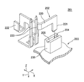
本発明の一実施の形態にかかる「バスバー組み付け構造」を図1〜9を用いて説明する。図1に示すように、バスバー組み付け構造1は、金属板にプレス加工等が施されて得られるバスバー2と、該バスバー2が組み付けられる合成樹脂製のハウジング3とで構成されている。
A “bus bar assembly structure” according to an embodiment of the present invention will be described with reference to FIGS. As shown in FIG. 1, the bus
上記バスバー2には、長方形板状の圧入片21と、電力が入力される部分である電源接続部22と、図示しない電子部品に電気接続される一対の雄型端子部23と、これらを連結した基部20と、が設けられている。
The
上記ハウジング3には、前記圧入片21が固定される固定部30が設けられている。この固定部30は、外形が直方体状に形成されており、圧入片21が圧入される圧入穴4と、基部20における圧入片21近傍部分が挿入される溝5と、が設けられている。
The
また、図1〜9中の矢印Yは、圧入片21の長手方向及び固定部30の高さ方向と平行な方向を表しており、矢印Xは、圧入片21の幅方向及び固定部30の幅方向と平行な方向を表しており、矢印Zは、圧入片21の厚み方向及び固定部30の厚み方向と平行な方向を表している。
Moreover, the arrow Y in FIGS. 1-9 represents the direction parallel to the longitudinal direction of the press-
上記圧入穴4は、図2,3に示すように、固定部30の上面から矢印Y方向に凹状に形成されている。圧入穴4は、開口部40と、底面41と、矢印X方向に対向配置された2つの面46,46と、矢印Z方向に対向配置された2つの面43,43及び2つの面44,44と、前記2つの面43,43と前記2つの面44,44の間に位置する段部7(特許請求の範囲の「所定位置」に相当する。)と、開口部40の近傍に設けられた4つのテーパ面42,42,45,45と、で構成されている。
As shown in FIGS. 2 and 3, the press-
上記2つの面46,46は、平面であり、互いに平行に配置されている。これら2つの面46,46間の間隔、すなわち圧入穴4の幅方向の寸法、は、圧入片21の幅方向の寸法よりも小さく形成されている。
The two
上記2つの面43,43は、平面であり、互いに平行に配置されている。これら2つの面43,43間の間隔、すなわち圧入穴4の厚み方向の寸法、は、圧入片21の厚み方向の寸法よりも若干大きく形成されている。
The two
上記2つの面44,44は、平面であり、互いに平行に配置されている。これら2つの面44,44間の間隔、すなわち圧入穴4の厚み方向の寸法、は、圧入片21の厚み方向の寸法よりも小さく形成されている。また、2つの面43,43は、2つの面44,44よりも開口部40側に配置されている。
The two
すなわち、圧入穴4は、段部7から開口部40側に、幅方向の寸法が圧入片21の幅方向の寸法よりも小さいとともに厚み方向の寸法が圧入片21の厚み方向の寸法よりも若干大きい部分6が設けられ、段部7から奥側の部分8は、幅方向の寸法が圧入片21の幅方向の寸法よりも小さく形成されているとともに厚み方向の寸法が圧入片21の厚み方向の寸法よりも小さく形成されている。
That is, the press-
上記構成のバスバー組み付け構造1においては、圧入片21が圧入穴4の2面46,46間、及び、2面44,44間に圧入されることにより固定部30に固定される。そして、圧入片21が固定部30に固定されることによりバスバー2がハウジング3に組み付けられる。
In the bus
続いて、バスバー組み付け構造1の作用効果について説明する。圧入片21が圧入穴4に圧入される際は、図4〜6に示すように段部7よりも開口部40側の部分6で圧入片21の位置出しが行われた後、図7〜9に示すようにさらに幅狭な奥側の部分8に圧入されることになるので、該奥側の部分8に圧入される際の斜め圧入を防止することができる。その結果、バスバー2がハウジング3に組み付けられた状態において、バスバー2のアライメント精度(特に一対の雄型端子部23先端のアライメント精度)を向上させることができる。また、圧入片21が段部7よりも奥側の部分8に真っ直ぐ(矢印Y方向)に圧入されることにより、該部分8の樹脂が削られることを防止でき、4つの面46,46,44,44で圧入片21を確実に保持することができるので、バスバー保持力の低下を防止することができる。また、バスバー組み付け構造1においては、段部7よりも開口部40側の部分6において圧入片21の一次圧入が行われ、段部8よりも奥側の部分8において圧入片21の二次圧入が行われる二段階圧入構造となっているので、挿入力のピーク値を低く抑えることができる。
Then, the effect of the bus
なお、前述した実施形態は本発明の代表的な形態を示したに過ぎず、本発明は、実施形態に限定されるものではない。即ち、本発明の骨子を逸脱しない範囲で種々変形して実施することができる。 In addition, embodiment mentioned above only showed the typical form of this invention, and this invention is not limited to embodiment. That is, various modifications can be made without departing from the scope of the present invention.
1 バスバー組み付け構造
2 バスバー
3 ハウジング
4 圧入穴
7 段部(所定位置)
21 圧入片
40 開口部
1
21 Press-
Claims (1)
前記バスバーに、長方形板状の圧入片が設けられ、
前記ハウジングに、前記圧入片が圧入される圧入穴が設けられ、
前記圧入穴の所定位置から開口部側に、幅方向の寸法が前記圧入片の幅方向の寸法よりも小さいとともに厚み方向の寸法が前記圧入片の厚み方向の寸法よりも大きい部分が設けられ、
前記圧入穴の所定位置から奥側の部分は、幅方向の寸法が前記圧入片の幅方向の寸法よりも小さく形成されているとともに厚み方向の寸法が前記圧入片の厚み方向の寸法よりも小さく形成されている
ことを特徴とするバスバー組み付け構造。 In a bus bar assembly structure including a bus bar and a housing to which the bus bar is assembled,
The bus bar is provided with a rectangular plate-shaped press-fitting piece,
The housing is provided with a press-fitting hole into which the press-fitting piece is press-fitted,
On the opening side from a predetermined position of the press-fitting hole, a portion in which the dimension in the width direction is smaller than the dimension in the width direction of the press-fitting piece and the dimension in the thickness direction is larger than the dimension in the thickness direction of the press-fitting piece,
The portion on the back side from the predetermined position of the press-fitting hole is formed such that the width-wise dimension is smaller than the width-wise dimension of the press-fitting piece and the thickness-wise dimension is smaller than the thickness-wise dimension of the press-fitting piece. A bus bar assembly structure characterized by being formed.
Priority Applications (1)
| Application Number | Priority Date | Filing Date | Title |
|---|---|---|---|
| JP2012006844A JP5806128B2 (en) | 2012-01-17 | 2012-01-17 | Busbar assembly structure |
Applications Claiming Priority (1)
| Application Number | Priority Date | Filing Date | Title |
|---|---|---|---|
| JP2012006844A JP5806128B2 (en) | 2012-01-17 | 2012-01-17 | Busbar assembly structure |
Publications (2)
| Publication Number | Publication Date |
|---|---|
| JP2013150377A JP2013150377A (en) | 2013-08-01 |
| JP5806128B2 true JP5806128B2 (en) | 2015-11-10 |
Family
ID=49047393
Family Applications (1)
| Application Number | Title | Priority Date | Filing Date |
|---|---|---|---|
| JP2012006844A Expired - Fee Related JP5806128B2 (en) | 2012-01-17 | 2012-01-17 | Busbar assembly structure |
Country Status (1)
| Country | Link |
|---|---|
| JP (1) | JP5806128B2 (en) |
Families Citing this family (2)
| Publication number | Priority date | Publication date | Assignee | Title |
|---|---|---|---|---|
| JP5844183B2 (en) * | 2012-03-09 | 2016-01-13 | 矢崎総業株式会社 | Terminal fixing structure |
| JP5916543B2 (en) * | 2012-07-06 | 2016-05-11 | 矢崎総業株式会社 | Busbar mounting structure |
Family Cites Families (4)
| Publication number | Priority date | Publication date | Assignee | Title |
|---|---|---|---|---|
| JP3693150B2 (en) * | 1999-05-10 | 2005-09-07 | 矢崎総業株式会社 | Terminal positioning structure |
| JP2005318693A (en) * | 2004-04-27 | 2005-11-10 | Auto Network Gijutsu Kenkyusho:Kk | Connection structure and connection method between press-fit terminal and bus bar |
| JP2009011039A (en) * | 2007-06-27 | 2009-01-15 | T An T:Kk | Wiring board and bus bar segment used therefor |
| JP5511495B2 (en) * | 2010-05-11 | 2014-06-04 | 矢崎総業株式会社 | Busbar mounting structure |
-
2012
- 2012-01-17 JP JP2012006844A patent/JP5806128B2/en not_active Expired - Fee Related
Also Published As
| Publication number | Publication date |
|---|---|
| JP2013150377A (en) | 2013-08-01 |
Similar Documents
| Publication | Publication Date | Title |
|---|---|---|
| JP5951290B2 (en) | Electrical connector | |
| US9300064B2 (en) | Connector | |
| JP6249676B2 (en) | Electrical connector | |
| JP3158697U (en) | Electrical connector | |
| US9516776B2 (en) | Electronic component assembly, connection structure between electronic component assembly and terminal fitting, and electrical connection box having electronic component assembly | |
| JP5358615B2 (en) | Circuit board electrical connector | |
| JP6118206B2 (en) | Nut press-fit holding structure | |
| JP5920876B2 (en) | Busbar assembly structure | |
| JP2016072222A (en) | connector | |
| JP6006356B2 (en) | Contact and connector using the contact | |
| JP2015220005A (en) | Board-to-board connector | |
| KR20130124353A (en) | Contact and connector with contacts | |
| JP5947679B2 (en) | Board connector | |
| JP2013168324A (en) | Connector | |
| WO2011040419A1 (en) | Mounting structure for substrate connector | |
| US8202123B1 (en) | Connector | |
| JP5806128B2 (en) | Busbar assembly structure | |
| JP2016091970A (en) | Socket terminal structure | |
| JP2014165065A (en) | Connector | |
| JP2014229383A (en) | Connector for substrate | |
| JP5888811B2 (en) | Busbar assembly structure | |
| JP6076953B2 (en) | Board terminal | |
| JP5872970B2 (en) | Connector terminal and connection structure between this connector terminal and mating terminal | |
| US20140187098A1 (en) | Connector | |
| JP6093645B2 (en) | Joint connector |
Legal Events
| Date | Code | Title | Description |
|---|---|---|---|
| A621 | Written request for application examination |
Free format text: JAPANESE INTERMEDIATE CODE: A621 Effective date: 20141219 |
|
| A977 | Report on retrieval |
Free format text: JAPANESE INTERMEDIATE CODE: A971007 Effective date: 20150727 |
|
| TRDD | Decision of grant or rejection written | ||
| A01 | Written decision to grant a patent or to grant a registration (utility model) |
Free format text: JAPANESE INTERMEDIATE CODE: A01 Effective date: 20150818 |
|
| A61 | First payment of annual fees (during grant procedure) |
Free format text: JAPANESE INTERMEDIATE CODE: A61 Effective date: 20150903 |
|
| R150 | Certificate of patent or registration of utility model |
Ref document number: 5806128 Country of ref document: JP Free format text: JAPANESE INTERMEDIATE CODE: R150 |
|
| R250 | Receipt of annual fees |
Free format text: JAPANESE INTERMEDIATE CODE: R250 |
|
| R250 | Receipt of annual fees |
Free format text: JAPANESE INTERMEDIATE CODE: R250 |
|
| R250 | Receipt of annual fees |
Free format text: JAPANESE INTERMEDIATE CODE: R250 |
|
| LAPS | Cancellation because of no payment of annual fees |