JP5772156B2 - Door system and elevator equipment - Google Patents
Door system and elevator equipment Download PDFInfo
- Publication number
- JP5772156B2 JP5772156B2 JP2011081925A JP2011081925A JP5772156B2 JP 5772156 B2 JP5772156 B2 JP 5772156B2 JP 2011081925 A JP2011081925 A JP 2011081925A JP 2011081925 A JP2011081925 A JP 2011081925A JP 5772156 B2 JP5772156 B2 JP 5772156B2
- Authority
- JP
- Japan
- Prior art keywords
- door
- camera
- marker
- foreign matter
- door system
- Prior art date
- Legal status (The legal status is an assumption and is not a legal conclusion. Google has not performed a legal analysis and makes no representation as to the accuracy of the status listed.)
- Expired - Fee Related
Links
- 239000003550 marker Substances 0.000 claims description 72
- 238000001514 detection method Methods 0.000 claims description 33
- 230000003287 optical effect Effects 0.000 claims description 6
- 208000033748 Device issues Diseases 0.000 claims 1
- 238000013459 approach Methods 0.000 claims 1
- 239000000126 substance Substances 0.000 description 15
- 239000000463 material Substances 0.000 description 5
- 238000010586 diagram Methods 0.000 description 4
- 239000000284 extract Substances 0.000 description 4
- 230000001360 synchronised effect Effects 0.000 description 4
- 238000003384 imaging method Methods 0.000 description 2
- 238000009434 installation Methods 0.000 description 2
- 230000005540 biological transmission Effects 0.000 description 1
- 230000000295 complement effect Effects 0.000 description 1
- 238000011109 contamination Methods 0.000 description 1
- 230000007423 decrease Effects 0.000 description 1
- 230000012447 hatching Effects 0.000 description 1
- 238000005286 illumination Methods 0.000 description 1
- 238000012423 maintenance Methods 0.000 description 1
- 230000007257 malfunction Effects 0.000 description 1
- 229910044991 metal oxide Inorganic materials 0.000 description 1
- 150000004706 metal oxides Chemical class 0.000 description 1
- 238000000034 method Methods 0.000 description 1
- 239000004065 semiconductor Substances 0.000 description 1
Images


Landscapes
- Elevator Door Apparatuses (AREA)
- Maintenance And Inspection Apparatuses For Elevators (AREA)
Description
本発明は、カメラの出力画像をもとにドアの開閉動作の制御を行うドアシステムおよびエレベータ装置に関するものである。 The present invention relates to a door system and an elevator apparatus that control the opening / closing operation of a door based on an output image of a camera.
自動ドアやエレベータなど、モータなどの駆動力によってドアが自動的に開閉する機器においては、ドアが閉鎖動作するときにドアとドアの間またはドアと枠の間に指や物を挟む、または、ドアが開放動作するときにドアと枠の間に指や物が引きこまれることにより、重大な事故につながる可能性がある。 In a device that automatically opens and closes by a driving force such as a motor, such as an automatic door or elevator, when a door is closed, a finger or an object is sandwiched between the doors or between the door and the frame, or When a door is opened, a finger or an object is drawn between the door and the frame, which may lead to a serious accident.
このような事故を防止するために、ドア上方にカメラを設置して出入り口近傍を撮像し、ドア閉鎖動作時に異物を検知した場合に閉鎖動作を停止させることで挟まれ事故を防止するドアシステムが提案されている(例えば特許文献1参照)。 In order to prevent such an accident, there is a door system that installs a camera above the door, images the vicinity of the entrance and exit, and detects a foreign object during the door closing operation to stop the closing operation and prevent the accident from being caught. It has been proposed (see, for example, Patent Document 1).
従来のドアシステムでは、上枠に設置したカメラにより出入り口近傍を撮像し、ドアに挟まれる可能性のある異物を検出している。このように上枠に設置したカメラにより出入り口近傍の異物を検出する場合、出入り口の大きさが変わると、カメラ出力画像に現れる異物の画素数が異なる。例えば、床に置かれた同じ大きさの異物がカメラに写った場合でも、小さなドアの上枠にカメラを設置した場合はカメラ出力画像に現れる異物の画素数は多くなり、大きなドアの上枠にカメラを設置した場合はカメラ出力画像に現れる異物の画素数は少なくなる。したがって、カメラを設置するドアの大きさに合わせて異物を検知するための画素数を設定しなければならないという問題があった。 In the conventional door system, the vicinity of the entrance / exit is imaged by a camera installed on the upper frame, and foreign matter that may be caught by the door is detected. In this way, when a foreign object in the vicinity of the entrance is detected by the camera installed on the upper frame, the number of pixels of the foreign object appearing in the camera output image varies as the size of the entrance changes. For example, even if a foreign object of the same size placed on the floor appears in the camera, if the camera is installed on the upper frame of a small door, the number of pixels of the foreign object appearing in the camera output image will increase, and the upper frame of the large door When a camera is installed in the camera, the number of foreign pixels appearing in the camera output image is reduced. Therefore, there has been a problem that the number of pixels for detecting a foreign object must be set in accordance with the size of the door on which the camera is installed.
本発明は前記のような問題を解決するためになされたもので、異なる大きさのドアにカメラを設置した場合でも異物を検知するための画素数を設定する必要のないドアシステムおよびエレベータ装置を提供することを目的としている。 The present invention has been made in order to solve the above-described problems. A door system and an elevator apparatus that do not need to set the number of pixels for detecting a foreign object even when a camera is installed on a door of a different size. It is intended to provide.
本発明によるドアシステムは、水平方向に対向した一対の縦枠と、縦枠の上端部同士を接続する上枠と、上枠に設置され縦枠および上枠で構成される出入り口近傍を撮影するカメラと、一対の縦枠のそれぞれに床面から同じ高さに設置されたマーカと、カメラの出力画像中のマーカの位置をもとにカメラからマーカまでの距離Rを算出するR演算部と、カメラの出力画像中のマーカの位置をもとに一方のマーカの端点A、カメラBおよび他方のマーカの端点Cからなる角ABCの大きさθを算出するθ演算部と、Rおよびθから出入り口の寸法を算出する枠体寸法判定部と、出入り口の寸法から異物判定の検出画素数を算出する異物判定画素数設定部と、カメラの出力画像および検出画素数から異物の有無を判定する異物判定部と、異物判定部の出力をもとにドアの開閉動作を制御する扉駆動制御装置とを備えるものである。 The door system according to the present invention photographs a pair of vertical frames facing in the horizontal direction, an upper frame that connects the upper ends of the vertical frames, and the vicinity of an entrance that is installed on the upper frame and includes the vertical frame and the upper frame. A camera, a marker installed on each of the pair of vertical frames at the same height from the floor, and an R calculation unit that calculates a distance R from the camera to the marker based on the position of the marker in the output image of the camera; A θ calculation unit for calculating the magnitude θ of an angle ABC composed of the end point A of one marker, the camera B and the end point C of the other marker based on the position of the marker in the output image of the camera; A frame size determination unit that calculates the entrance / exit dimension, a foreign object determination pixel number setting unit that calculates the number of detected pixels for foreign object determination from the entrance / exit dimension, and a foreign object that determines the presence / absence of a foreign object from the output image and the detected pixel number of the camera Judgment unit and foreign matter judgment unit In which and a door drive control device for controlling the opening and closing operation of the door based on the output.
本発明によれば、水平方向に対向した一対の縦枠と、縦枠の上端部同士を接続する上枠と、上枠に設置され縦枠および上枠で構成される出入り口近傍を撮影するカメラと、一対の縦枠のそれぞれに床面から同じ高さに設置されたマーカと、カメラの出力画像中のマーカの位置をもとにカメラからマーカまでの距離Rを算出するR演算部と、カメラの出力画像中のマーカの位置をもとに一方のマーカの端点A、カメラBおよび他方のマーカの端点Cからなる角ABCの大きさθを算出するθ演算部と、Rおよびθから出入り口の寸法を算出する枠体寸法判定部と、出入り口の寸法から異物判定の検出画素数を算出する異物判定画素数設定部と、カメラの出力画像および検出画素数から異物の有無を判定する異物判定部と、異物判定部の出力をもとにドアの開閉動作を制御する扉駆動制御装置とを備えているので、ドアの大きさによって異物を検知する画素数を設定する必要が無く、異物の検知を高精度に行うことができる。 According to the present invention, a pair of vertical frames facing each other in the horizontal direction, an upper frame that connects the upper ends of the vertical frames, and a camera that shoots the vicinity of an entrance that is installed in the upper frame and includes the vertical frame and the upper frame. A marker installed at the same height from the floor on each of the pair of vertical frames, an R calculation unit that calculates a distance R from the camera to the marker based on the position of the marker in the output image of the camera, Based on the position of the marker in the output image of the camera, a θ calculator for calculating the magnitude θ of the angle ABC composed of the end point A of one marker, the camera B, and the end point C of the other marker, and an entrance / exit from R and θ A frame size determination unit that calculates the size of the object, a foreign object determination pixel number setting unit that calculates the number of detected pixels for foreign object determination from the entrance and exit dimensions, and a foreign object determination that determines the presence or absence of a foreign object from the output image and the detected pixel number of the camera Based on the output of the Since a door drive control device for controlling the opening and closing operation of the door, there is no need to set the number of pixels for detecting the foreign substance by the size of the door, it is possible to perform the detection of the foreign object with high accuracy.
実施の形態1
図1は、本発明の実施の形態1によるドアシステム10の概略構成を示したものである。自動で開閉するドア11は、枠体12の内側に形成されており、枠体12は、左右の縦枠12aおよび12bと、縦枠12aおよび12bの上端を互いに連結する上枠12cにより構成されている。マーカ20aおよび20bは、それぞれ、縦枠12aおよび12bに設置されており、マーカ20aおよび20bの下端は、床面13から高さHの位置にある。カメラ30および投光器40は、上枠12cに設置されており、画像処理装置50に接続されている。画像処理装置50、システム制御装置90、扉開閉制御装置60、および、扉駆動装置70は、直列に接続されている。システム制御装置90の出力は、警報装置80にも入力されている。
FIG. 1 shows a schematic configuration of a
マーカ20aおよび20bの高さ方向の長さはLであり、画像処理装置50において確実に認識するために光学的な再帰性反射の特性を有する素材であることが望ましい。再帰性反射の特性を有する素材としては、例えば、コーナーキューブなどがある。
The length of the
カメラ30は、上枠12cに下方向を撮影するように設置されており、出入り口近傍14を撮影し、画像データを画像処理装置50に出力する。ここで、画像データは2次元の画像情報であり、画素値を持った画素の集合である。画素値は、その画素に対応する出入り口近傍14の位置からの反射光量の強度に比例した値である。カメラ30は、具体的にはCCD(Charge Coupled Device)カメラやCMOS(Complementary Metal Oxide Semiconductor)カメラなどの撮像装置であり、2次元配列した画像素子と出入り口近傍14からの反射光を画像素子上に結像するレンズとを有する。カメラ30は、マーカ20aおよび20bを含む領域を撮影する。また、カメラ30は、画像処理装置50からの指示により、投光器40の点灯時に撮影した画像データと、投光器40が消灯時に撮影した画像データとを出力する。また、カメラ30に、投光器40から照射される波長の光を選択的に透過する光学フィルタを設置しても良い。カメラ30に光学フィルタを設置することにより、太陽光や他の光源による影響を抑制することができ、誤検知を減らすことができる。
The
投光器40は、上枠12cに下向きに設置され、カメラ30が撮影するマーカ20aおよび20bを含む出入り口近傍14を照射する。投光器40の光源は、赤外線LED(Light Emitting Diode)等の発光ダイオード、レーザダイオード、ランプ等、マーカ20aおよび20bを含む出入り口近傍14を照射できるものであればよい。また、投光器40は効率よく照射するためにレンズユニットを含んでいても良く、レンズユニットには凸型又は凹型レンズ、フレネルレンズ、円柱レンズ、円柱フレネルレンズ等の1つの又は複数を組み合わせたレンズなどがある。
The
画像処理装置50は、カメラ30の出力である画像データを取得し、出入り口近傍14の異物の有無を判断する。
The
図2は、本発明の実施の形態1によるドアシステムの構成を示すブロック図である。システム制御装置90は、ドアシステム全体の制御を行うものである。同期駆動部51は、システム制御装置90からの指示に従って、投光器40を動作させた状態でカメラ30を動作させ、カメラ30は投光器点灯時撮像画像を画像情報記憶部52に出力する。さらに、同期駆動部51は、投光器40を動作させない状態でカメラ30を動作させ、カメラ30は投光器消灯時撮像画像を画像情報記憶部52に出力する。差分画像演算部53は、画像情報記憶部52に記憶された投光器点灯時撮像画像と投光器消灯時撮像画像との差分画像を作成し、マーカ認識部54および異物判定部59に出力する。マーカ認識部54は、差分画像演算部53の出力である差分画像から、マーカ位置を特定し、その位置情報をθ演算部55aと検出領域設定部58とに出力する。
FIG. 2 is a block diagram showing the configuration of the door system according to
カメラ30から出力される画像データの例である図3を用いて、マーカ認識部54の動作について説明する。図3では、画像データの中に、ドア11、床面13、出入り口近傍14、縦枠12aおよび12b、マーカ20aおよび20bが含まれている。マーカ20aおよび20bは、光学的な再帰性反射の特性を有する素材であるため、投光器点灯時撮像画像と投光器消灯時撮像画像とで画素値が大きく異なる。よって、投光器点灯時撮像画像と投光器消灯時撮像画像との差分画像においてマーカ20aおよび20bの部分のみが大きな値を持っており、閾値処理などによって差分画像からマーカ20aおよび20bの位置を特定できる。マーカ認識部54は、特定したマーカ20aおよび20bの画像データであるマーカ画像を、検出領域設定部58に出力する。また、特定したマーカ20aおよび20bの位置から、マーカ20aの上辺とマーカ20bの上辺の間の距離であるΔ’、および、マーカ20aの下辺とマーカ20bの下辺の間の距離であるΔを求め、θ演算部55aに出力する。ここで、投光器点灯時撮像画像と投光器消灯時撮像画像の差分画像からマーカ20aおよび20bの位置を検出しているので、外乱光の影響が抑制され、撮像画像中のマーカの位置を精度よく認識できる。
The operation of the
θ演算部55aとR演算部55bの動作について、図3と図4とを用いて説明する。図3は、カメラ30から出力される画像データの例である。図4は、マーカの設置位置を説明するための図であり、出入り口近傍14を正面から見た図である。
The operations of the
図3において、マーカ20aの上辺とマーカ20bの上辺の間の距離であるΔ’は、図4における角θ’に対応するものであり、マーカ20aの下辺とマーカ20bの下辺の間の距離であるΔは、図4における角θに対応する。これらの関係は、次式のように表せる。
In FIG. 3, Δ ′, which is the distance between the upper side of the
![]()
![]()
式(1)において、aはカメラの特性により決定される量であり、予めθ演算部55aに記憶しておくものとする。θ演算部55aは、式(1)によりθおよびθ’を求め、θの値を枠体寸法判定部56に出力するとともに、θおよびθ’の値をR演算部55bに出力する。
In Expression (1), a is an amount determined by the characteristics of the camera, and is preliminarily stored in the
次に、カメラ30からマーカ20aまたは20bの下端までの距離Rは、以下の式で表される。
Next, the distance R from the

式(2)において、Lはマーカ20aおよび20bの高さ方向の長さであり、予めR演算部55bに記憶しておくものとする。R演算部55bは、式(2)によりRを求め、枠体寸法判定部56に出力する。
In Expression (2), L is the length of the
枠体寸法判定部56では、以下の式を用いてドア11の高さHHと横幅JJを求める。
The frame
式(3)において、Hは床面13からマーカ20aまたは20bの下端までの高さであり、予め枠体寸法判定部56に記憶しておくものとする。枠体寸法判定部56は、式(3)により求めたHHおよびJJの値を、異物判定画素数設定部57に出力する。
In Expression (3), H is the height from the
異物判定画素数設定部57は、予めカメラ30から距離Dだけ離れた被写体を撮影したときの1画素あたりの長さである「分解能」の情報を記憶しており、このカメラの分解能と、枠体寸法判定部56から出力されたHHおよびJJの値とから、床面13付近の1画素あたりの長さが求められる。次に、検出対象の大きさに応じて、カメラ30の出力画像における検出対象の画素数である異物判定画素数U1を決定し、伊津部判定部59に出力する。例えば、エレベータの出入り口近傍14において挟まれは引き込まれの可能性がある「幼児の手」や「ペットの紐」を検出対象とする場合、これらの大きさに対応した画素数を異物判定画素数U1として出力する。
The foreign substance determination pixel
検出領域設定部58の動作について、図5および図6を用いて説明する。図5はマーカ認識部54から検出領域設定部58に入力されたマーカ画像の例であり、図6は図5の一部を拡大したものである。検出領域設定部58は、図5に示されたマーカ画像から、マーカ20bの上辺の中心点P1(x1、y1)とマーカ20aの上辺の中心点P2(x2、y2)を求める。ここで、基準となる点P1(x1、y1)およびP2(x2、y2)は、マーカ20aおよび20bの中心点や、マーカ20aおよび20bの下辺の中心点としても良いが、マーカ20aおよび20bの上辺の中心点がカメラ30に近いため、最も精度良く位置を特定することができる。
The operation of the detection
図6は、図5におけるP1およびP2の周囲を拡大した図である。検出領域設定部58は、P1とP2を結ぶ直線C1を求め、直線C1を含む画素群であるG1を求める。図6において、G1は斜線で示された画素群である。検出領域設定部58は、画素群G1を異物判定領域として異物判定部59に出力する。このように、異物を判定する領域をマーカ20aおよび20bの上辺の中心点を結んだ領域に限定することにより、異物の検出を出入り口近傍14に限定することができ、異物の誤検出を抑制することができる。
FIG. 6 is an enlarged view around P 1 and P 2 in FIG. Detection
次に、異物判定部59による異物判定の動作について説明する。異物判定部59では、差分画像演算部の出力である差分画像から異物判定領域G1を抽出し、この中で一定以上の値を持つ領域を抽出する。次に、抽出された領域が異物判定画素数U1に相当する場合、これを異物として検出する。異物判定部59において異物を検出した場合、異物を検出したことを示す信号をシステム制御装置90に出力する。
Next, the foreign substance determination operation by the foreign
以上に説明した画像処理装置50の動作の例を、図7のフローチャートを用いて説明する。画像処理装置50は、システム制御装置90の指令により、検出モードおよび設定モードの2つのモードを実行する。設定モードでは、画像情報記憶部52において投光器点灯時撮影画像z1cおよび投光器消灯時撮影画像z2cを取得し(S003、S004)、差分画像演算部53により差分画像z3cを生成する(S005)。次に、マーカ認識部54において、差分画像z3cからマーカ位置を判定する(S006)。マーカ位置から、θ演算部55aおよびR演算部55bにおいてθおよびRの値を求め、さらに、θおよびRの値から、枠体寸法判定部56においてドア11の高さと横幅を求める。この結果から、異物判定画素数設定部57において、異物判定画素数を求める(S007)。また、検出領域設定部58では、マーカ認識部54の出力から、異物判定領域G1を求める(S008)。
An example of the operation of the
一方、検出モードでは、システム制御装置90の指令により、検出動作を開始する(S009)。まず、ステップS003からS005と同様に、画像情報記憶部52および差分画像演算部53において差分画像z3aを生成する(S010、S011、S012)。次に、予め設定された時間だけ待機し(S013)、再び、画像情報記憶部52および差分画像演算部53において差分画像z3bを生成する(S010、S011、S012)。異物判定部59では、これらの異なる時刻で取得した差分画像z3aと差分画像z3bの差分画像を求める(S017)。ステップS017で求めた差分画像から異物判定領域G1の画素データを抽出し、この中で予め設定された閾値以上の値を持つ画素領域S1を抽出する(S018)。最後に、画素領域S1が異物判定画素数U1に相当する場合(S019)、これを異物ありと判定し、システム制御装置90に異物を検出したことを示す信号を出力する(S020)。ここで、投光器点灯時撮影画像と投光器消灯時撮影画像の撮影間隔を十分短時間とすることで、時間変換する太陽光やその他の外乱光による誤動作を抑制することができる。
On the other hand, in the detection mode, a detection operation is started in response to a command from the system control device 90 (S009). First, similarly to steps S003 to S005, the image
扉開閉制御装置60は、扉駆動装置70を制御する。扉駆動装置70は、ドア11の開閉動作を行う。扉駆動装置70は、例えば、モータなどの駆動源と、その駆動源から駆動力の供給を受けてドアを開閉するためのワイヤや歯車などの駆動力伝達部材とを、有する。警報装置80は、例えば、スピーカ、照明、モニタなどを用いて、音声、ブザー音、光、映像などによって、ドア11の近くにいる人に警告を発する。システム制御装置90は、画像処理装置50、扉開閉制御装置60、および、警報装置80と接続されている。
The door opening /
図8および図9のフローチャートを用いて、ドアの開閉および警報の発報の動作について説明する。図8は、ドアシステム10がドア11の閉鎖状態から開放動作を行うとき動作を説明したフローチャートである。システム制御装置90は、検出動作を開始する(S023)。システム制御装置90が画像処理装置50から異物を検出したことを示す信号を受け取った場合(S024)、異物があると判断し、警報装置80に対して警告動作の指示を行い、扉開閉制御装置60にドア11の閉鎖状態維持を指示する。警報装置80は、音の発生、発光、画像の表示等の警告動作を行い(S025)、扉開閉制御装置60は扉駆動装置70を制御してドア11が閉鎖された状態を維持する(S026)。ドア11の閉鎖状態が維持されている状態で、システム制御装置90が画像処理装置50から異物を検出したことを示す信号を再度受け取った場合(S027)、異物が出入り口近傍14に異物が引き続き存在していると判断し、警報装置80に再び警告動作を行わせ(S028)、扉開閉制御装置60を制御して、ドア11を低速にて開放する動作を開始する(S029)。その後、システム制御装置90は、画像処理装置50の検出動作を停止し(S030)、ドア11が開放状態となるまで低速にて開放する動作を継続する(S031)。
The operation of opening / closing the door and issuing an alarm will be described with reference to the flowcharts of FIGS. FIG. 8 is a flowchart for explaining the operation when the
一方、ステップS024あるいはステップS027においてシステム制御装置90が画像処理装置50から異物を検出したことを示す信号を受け取らなかった場合、異物はないと判断し、扉開閉制御装置60を制御してドア11を通常の速度で開放する動作を開始し(S032)、画像処理装置50の検出動作を停止し(S033)、ドア11が開放状態なるまで通常の速度で開放する動作を継続する(S034)。
On the other hand, if the
図8に示したフローチャートのようにドア11の開放動作を行うことにより、出入り口近傍14内に異物が存在すると判断された場合に、ドア11の開放動作を開始する前に、警報装置80が異物の存在をドア11付近の人に警告を発する。これにより、警告された人は、ドア11の近くの人や物がドア11に引き込まれる可能性があることを知ることができる。さらに、再度、異物があると判断された場合に、ドア11を低速で開放するため、人や物がドア11に引き込まれる可能性を少なくすることができる。
When the
図9は、ドアシステム10がドア11の開放状態から閉鎖動作を行うとき動作を説明したフローチャートである。システム制御装置90は、検出動作を開始する(S037)。システム制御装置90が画像処理装置50から異物を検出したことを示す信号を受け取った場合(S038)、異物があると判断し、扉開閉制御装置60にドア11の開放状態の維持を指示し、画像処理装置50に検出動作を継続させる。
FIG. 9 is a flowchart illustrating the operation when the
一方、ステップS038において画像処理装置50から異物を検出したことを示す信号を受け取らなかった場合、扉開閉制御装置60に対してドア11の閉鎖動作開始を指示する(S039)。ドア11の閉鎖動作中もシステム制御装置90は画像処理装置50に検出動作を継続させ(S040)、画像処理装置50から異物を検出したことを示す信号を受け取ら内限りはドア11の閉鎖動作を継続する(S041)。ドア11の閉鎖状態となった場合は(S042)、画像処理装置50の検出動作を停止し(S043)、動作を終了する。
On the other hand, if no signal indicating that a foreign object has been detected is received from the
ドア11が閉鎖状態となる前にシステム制御装置90が画像処理装置50から異物を検出したことを示す信号を受け取った場合、扉開閉制御装置60を制御してドア11を開放状態に戻す(S044)。
When the
図9に示したフローチャートのようにドア11の閉鎖動作を行うことにより、出入り口近傍14内に異物が存在すると判断された場合に、ドア11が閉鎖動作開始前であればドア11の開放状態を維持し、ドア11が閉鎖動作中であればドア11の閉鎖動作を中断して開放状態に戻す。これにより、人や物がドア11に引き込まれる可能性を少なくすることができる。
When the
実施の形態2.
本発明の実施の形態2によるドアシステム10を実施の形態1によるドアシステム10と比べると、マーカ20aおよび20bが特定のパターン模様を持つマーカ21aおよび21bに変わっている以外は、同じである。
The
本発明の実施の形態2によるドアシステム10では、マーカ21aおよび21bが特定のパターン模様を持っており、画像処理装置50のマーカ認識部54において画像データ中のパターンを抽出し、R演算部55bがマーカ認識部54において抽出されたパターンの長さからカメラからマーカまでの距離Rを求めている。
In the
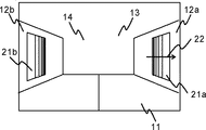
図10は、本発明の実施の形態2によるカメラ30から出力される画像データの例である。図10に示すように、マーカ21aおよび21bのピッチパターンのピッチ間隔は、矢印22の方向に向かって、すなわち、カメラ30に近づくにつれて単調に増加している。本発明の実施の形態2においては、マーカ認識部54は、差分画像演算部53の出力からマーカ21aおよび21bのピッチパターンを認識し、ピッチ間隔を抽出する。
FIG. 10 is an example of image data output from the
図11は、マーカ認識部54において抽出されたピッチ間隔の例である。横軸は図10における矢印22の方向の画素数、縦軸は画素値を表している。図12は、d(i)、d(i+1)、d(i+2)の3つの画素数とカメラからマーカまでの距離Rとの関係を、示している。横軸は、(i)、(i+1)、(i+2)それぞれのピッチの位置を示しており、縦軸は、検出されたd(i)、d(i+1)、d(i+2)の画素数を示している。例えば、カメラからマーカまでの距離が比較的短いR1のときは、d(i)、d(i+1)、d(i+2)のそれぞれの値は大きくなり、なおかつ、d(i+2)とd(i)との差であるピッチ間隔増加率I(R=R1)も大きくなる。カメラからマーカまでの距離が比較的長いR3のときは、d(i)、d(i+1)、d(i+2)のそれぞれの値は小さくなり、なおかつ、d(i+2)とd(i)との差であるピッチ間隔増加率I(R=R3)も小さくなる。マーカ認識部54は、上記のようにして求められたピッチ間隔増加率Iを、R演算部55bに出力する。
FIG. 11 is an example of pitch intervals extracted by the
R演算部55bでは、マーカ認識部54の出力であるピッチ間隔増加率Iと、θ演算部の出力であるθとから、カメラからマーカまでの距離Rを求める。
In the R calculation unit 55b, the distance R from the camera to the marker is obtained from the pitch interval increase rate I which is the output of the
このように、画像データにおけるピッチパターンの画素数を元にカメラからマーカまでの距離Rを求めることにより、マーカ21aおよび21bの一部が汚れた場合においてもカメラからマーカまでの距離Rを精度良く求めることができる。
Thus, by obtaining the distance R from the camera to the marker based on the number of pixels of the pitch pattern in the image data, the distance R from the camera to the marker can be accurately determined even when some of the
実施の形態3.
本発明の実施の形態3によるドアシステム10を実施の形態1によるドアシステム10と比べると、検出領域設定部58による異物判定領域の設定方法が異なる。図13は、本発明の実施の形態3による検出領域設定部58の動作を説明するための図である。検出領域設定部58は、マーカ20bの上辺の中心点P1(x1、y1)とマーカ20aの上辺の中心点P2(x2、y2)を結ぶ直線C1を求める。次に直線C1を中心として図13の縦軸方向に2N+1画素の範囲を異物判定領域G2とする。ここで、Nは、検出領域設定部58に予め設定されている値である。
Embodiment 3 FIG.
When the
このように、異物判定領域を広く設定することにより、出入り口近傍14において幅広く異物検知を行うことが可能となる。また、出入り口近傍14においてドア11と直交する方向に細長い形状の異物がある場合でも、検出することが可能となる。
In this way, by setting the foreign object determination area widely, foreign object detection can be performed widely in the vicinity of the entrance /
実施の形態4.
図14は、本発明の実施の形態4によるドアシステム10の概略構成を示したものである。図14を実施の形態1によるドアシステム10の概略構成である図2と比べると、マーカ20aおよび20bが、カメラ30と同期して自発光するマーカ22aおよび22bに変わった以外は、同じである。
Embodiment 4 FIG.
FIG. 14 shows a schematic configuration of the
本発明の実施の形態4によるドアシステム10では、同期駆動部51は、システム制御装置90からの指示に従って、マーカ22aおよび22bを発光させた状態でカメラ30を動作させ、カメラ30はマーカ発光時撮像画像を画像情報記憶部52に出力する。さらに、同期駆動部51は、マーカ22aおよび22bを発光させない状態でカメラ30を動作させ、カメラ30はマーカ消灯時撮像画像を画像情報記憶部52に出力する。なお、マーカ22aおよび22bから発光される光の波長は単色であることが望ましく、カメラ30にマーカ22aおよび22bから発光される波長の光を選択的に透過するフィルタを設けることにより、太陽光などの外乱光の影響を抑制することができる。
In the
実施の形態5.
本発明の実施の形態5によるドアシステム10を実施の形態1によるドアシステム10と比べると、マーカ20aおよび20bが取り外し可能である以外は、同じである。
Embodiment 5 FIG.
The
本発明の実施の形態5によるドアシステム10では、マーカ20aおよび20bとして取り外し可能なものと用いる。例えば、表面は光学的な再帰性反射の特性を有する素材で
あり、裏面は粘着性を備えるものとする。本発明の実施の形態5によるドアシステム10では、ドアシステム10の据え付け時または保守作業時のみ、マーカ20aおよび20bを所定の位置に設置し、画像処理装置50に対して設定モードを実行し、設定モードの実行が完了した後にマーカ20aおよび20bを取り外す。
In the
このように、マーカ20aおよび20bを取り外し可能とすることにより、マーカが汚れることによりマーカの認識精度が低下するといったことを防ぐことができる。また、ドアシステムの意匠上の影響も排除できる。
As described above, by making the
12a 縦枠
12b 縦枠
12c 上枠
20a マーカ
20b マーカ
30 カメラ
55a θ演算部
55b R演算部
56 枠体寸法判定部56
57 異物判定画素数設定部
59 異物判定部
60 扉開閉制御装置
12a
57 Foreign matter determination pixel
Claims (12)
前記縦枠の上端部同士を接続する上枠と、
前記上枠に設置され前記縦枠および前記上枠で構成される出入り口近傍を撮影するカメラと、
前記一対の縦枠のそれぞれに床面から同じ高さに設置されたマーカと、
前記カメラの出力画像中の前記マーカの位置をもとに前記カメラから前記マーカまでの距離Rを算出するR演算部と、
前記カメラの出力画像中の前記マーカの位置をもとに一方の前記マーカの端点A、前記カメラBおよび他方の前記マーカの端点Cからなる角ABCの大きさθを算出するθ演算部と、
前記Rおよび前記θから前記出入り口の寸法を算出する枠体寸法判定部と、
前記出入り口の寸法から異物判定の検出画素数を算出する異物判定画素数設定部と、
前記カメラの出力画像および前記検出画素数から異物の有無を判定する異物判定部と、
前記異物判定部の出力をもとにドアの開閉動作を制御する扉駆動制御装置と
を備えるドアシステム。 A pair of vertical frames facing horizontally,
An upper frame connecting upper ends of the vertical frames;
A camera that is installed in the upper frame and shoots the vicinity of the entrance and exit composed of the vertical frame and the upper frame;
Markers installed at the same height from the floor surface in each of the pair of vertical frames,
An R calculator that calculates a distance R from the camera to the marker based on the position of the marker in the output image of the camera;
A θ calculation unit that calculates a magnitude θ of an angle ABC composed of an end point A of the one marker, the camera B, and an end point C of the other marker based on the position of the marker in the output image of the camera;
A frame size determination unit that calculates the size of the doorway from the R and the θ;
A foreign matter determination pixel number setting unit for calculating the number of detection pixels for foreign matter determination from the dimensions of the doorway;
A foreign matter determination unit for determining the presence or absence of foreign matter from the output image of the camera and the number of detected pixels;
A door system comprising: a door drive control device that controls an opening / closing operation of the door based on an output of the foreign matter determination unit.
11. The door drive control device performs control for interrupting the door closing operation and returning the door to the open state when the foreign object determining unit determines that there is a foreign object during the door closing operation. The door system according to any one of the above.
Priority Applications (1)
| Application Number | Priority Date | Filing Date | Title |
|---|---|---|---|
| JP2011081925A JP5772156B2 (en) | 2011-04-01 | 2011-04-01 | Door system and elevator equipment |
Applications Claiming Priority (1)
| Application Number | Priority Date | Filing Date | Title |
|---|---|---|---|
| JP2011081925A JP5772156B2 (en) | 2011-04-01 | 2011-04-01 | Door system and elevator equipment |
Publications (2)
| Publication Number | Publication Date |
|---|---|
| JP2012214285A JP2012214285A (en) | 2012-11-08 |
| JP5772156B2 true JP5772156B2 (en) | 2015-09-02 |
Family
ID=47267517
Family Applications (1)
| Application Number | Title | Priority Date | Filing Date |
|---|---|---|---|
| JP2011081925A Expired - Fee Related JP5772156B2 (en) | 2011-04-01 | 2011-04-01 | Door system and elevator equipment |
Country Status (1)
| Country | Link |
|---|---|
| JP (1) | JP5772156B2 (en) |
Families Citing this family (5)
| Publication number | Priority date | Publication date | Assignee | Title |
|---|---|---|---|---|
| CN104340827B (en) * | 2013-07-26 | 2016-01-27 | 上海三菱电梯有限公司 | The Antipinch detection method of sliding door apparatus and detecting device |
| JP6270948B1 (en) * | 2016-09-21 | 2018-01-31 | 東芝エレベータ株式会社 | Elevator user detection system |
| CN107187980B (en) * | 2017-05-26 | 2019-03-15 | 杭州光珀智能科技有限公司 | The detection method and detection device of elevator door folding in a kind of lift appliance |
| JP6702578B1 (en) * | 2019-03-18 | 2020-06-03 | 東芝エレベータ株式会社 | Elevator user detection system |
| JP6673617B1 (en) * | 2019-03-20 | 2020-03-25 | 東芝エレベータ株式会社 | Image detection device |
Family Cites Families (4)
| Publication number | Priority date | Publication date | Assignee | Title |
|---|---|---|---|---|
| JP2008075360A (en) * | 2006-09-22 | 2008-04-03 | Saxa Inc | Automatic door sensor |
| JP2009242045A (en) * | 2008-03-31 | 2009-10-22 | Mitsubishi Electric Corp | Door device |
| JP4664394B2 (en) * | 2008-05-23 | 2011-04-06 | 株式会社日立製作所 | Elevator door safety device and safety control method |
| JP5690504B2 (en) * | 2010-05-14 | 2015-03-25 | 株式会社日立製作所 | Safety elevator |
-
2011
- 2011-04-01 JP JP2011081925A patent/JP5772156B2/en not_active Expired - Fee Related
Also Published As
| Publication number | Publication date |
|---|---|
| JP2012214285A (en) | 2012-11-08 |
Similar Documents
| Publication | Publication Date | Title |
|---|---|---|
| US11381753B2 (en) | Adjusting camera exposure for three-dimensional depth sensing and two-dimensional imaging | |
| KR102619558B1 (en) | Control system of autonomous vehicle and control method thereof | |
| JP5772156B2 (en) | Door system and elevator equipment | |
| WO2019179357A1 (en) | Photographing method and device, intelligent equipment and storage medium | |
| JP6766071B2 (en) | Image acquisition device for vehicles and vehicles equipped with it | |
| JP2019508717A5 (en) | Method and apparatus for illumination invariant image sensor of automatic subject detection and vision system | |
| TWI478107B (en) | Apparatus and method for controlling gates | |
| JP2016519941A5 (en) | ||
| JP2007186915A (en) | Power window device | |
| JPWO2010004763A1 (en) | Three-dimensional shape measuring apparatus, integrated circuit, and method | |
| JP6811661B2 (en) | Mobile imager and mobile | |
| CN112995619A (en) | Projection display control method and device and projection system | |
| JP5605565B2 (en) | Object identification device and object identification method | |
| KR100756009B1 (en) | 3D Surface Image Acquisition System of Container and Its Method | |
| JP6272157B2 (en) | Elevator apparatus and elevator control method | |
| JP2013114536A (en) | Safety support apparatus and safety support method | |
| JP2018047993A (en) | User detection system for elevator | |
| JP2009239598A5 (en) | ||
| KR20080083469A (en) | Container monitoring system | |
| JP2010235283A (en) | Elevator safety device | |
| JP2018197910A (en) | Biometric measurement device | |
| JP2010235284A (en) | Elevator safety device | |
| WO2020059674A3 (en) | Method for measuring distance of image displayed on television camera | |
| CN110147713A (en) | A kind of method for detecting fatigue driving and system | |
| KR102333490B1 (en) | Heterogeneous image processing device |
Legal Events
| Date | Code | Title | Description |
|---|---|---|---|
| A621 | Written request for application examination |
Free format text: JAPANESE INTERMEDIATE CODE: A621 Effective date: 20140122 |
|
| RD01 | Notification of change of attorney |
Free format text: JAPANESE INTERMEDIATE CODE: A7421 Effective date: 20140326 |
|
| A131 | Notification of reasons for refusal |
Free format text: JAPANESE INTERMEDIATE CODE: A131 Effective date: 20141125 |
|
| A521 | Request for written amendment filed |
Free format text: JAPANESE INTERMEDIATE CODE: A523 Effective date: 20141215 |
|
| TRDD | Decision of grant or rejection written | ||
| A01 | Written decision to grant a patent or to grant a registration (utility model) |
Free format text: JAPANESE INTERMEDIATE CODE: A01 Effective date: 20150602 |
|
| A61 | First payment of annual fees (during grant procedure) |
Free format text: JAPANESE INTERMEDIATE CODE: A61 Effective date: 20150615 |
|
| R151 | Written notification of patent or utility model registration |
Ref document number: 5772156 Country of ref document: JP Free format text: JAPANESE INTERMEDIATE CODE: R151 |
|
| R250 | Receipt of annual fees |
Free format text: JAPANESE INTERMEDIATE CODE: R250 |
|
| R250 | Receipt of annual fees |
Free format text: JAPANESE INTERMEDIATE CODE: R250 |
|
| R250 | Receipt of annual fees |
Free format text: JAPANESE INTERMEDIATE CODE: R250 |
|
| R250 | Receipt of annual fees |
Free format text: JAPANESE INTERMEDIATE CODE: R250 |
|
| R250 | Receipt of annual fees |
Free format text: JAPANESE INTERMEDIATE CODE: R250 |
|
| LAPS | Cancellation because of no payment of annual fees |