JP5582671B2 - Exhaust gas purification catalyst, exhaust gas purification catalyst recovery method, and exhaust gas purification catalyst system - Google Patents
Exhaust gas purification catalyst, exhaust gas purification catalyst recovery method, and exhaust gas purification catalyst system Download PDFInfo
- Publication number
- JP5582671B2 JP5582671B2 JP2006117958A JP2006117958A JP5582671B2 JP 5582671 B2 JP5582671 B2 JP 5582671B2 JP 2006117958 A JP2006117958 A JP 2006117958A JP 2006117958 A JP2006117958 A JP 2006117958A JP 5582671 B2 JP5582671 B2 JP 5582671B2
- Authority
- JP
- Japan
- Prior art keywords
- exhaust gas
- catalyst
- gas purification
- purification catalyst
- noble metal
- Prior art date
- Legal status (The legal status is an assumption and is not a legal conclusion. Google has not performed a legal analysis and makes no representation as to the accuracy of the status listed.)
- Expired - Fee Related
Links
Images


Classifications
-
- B—PERFORMING OPERATIONS; TRANSPORTING
- B01—PHYSICAL OR CHEMICAL PROCESSES OR APPARATUS IN GENERAL
- B01D—SEPARATION
- B01D53/00—Separation of gases or vapours; Recovering vapours of volatile solvents from gases; Chemical or biological purification of waste gases, e.g. engine exhaust gases, smoke, fumes, flue gases, aerosols
- B01D53/34—Chemical or biological purification of waste gases
- B01D53/92—Chemical or biological purification of waste gases of engine exhaust gases
- B01D53/94—Chemical or biological purification of waste gases of engine exhaust gases by catalytic processes
- B01D53/9445—Simultaneously removing carbon monoxide, hydrocarbons or nitrogen oxides making use of three-way catalysts [TWC] or four-way-catalysts [FWC]
- B01D53/945—Simultaneously removing carbon monoxide, hydrocarbons or nitrogen oxides making use of three-way catalysts [TWC] or four-way-catalysts [FWC] characterised by a specific catalyst
-
- B—PERFORMING OPERATIONS; TRANSPORTING
- B01—PHYSICAL OR CHEMICAL PROCESSES OR APPARATUS IN GENERAL
- B01J—CHEMICAL OR PHYSICAL PROCESSES, e.g. CATALYSIS OR COLLOID CHEMISTRY; THEIR RELEVANT APPARATUS
- B01J23/00—Catalysts comprising metals or metal oxides or hydroxides, not provided for in group B01J21/00
- B01J23/38—Catalysts comprising metals or metal oxides or hydroxides, not provided for in group B01J21/00 of noble metals
- B01J23/54—Catalysts comprising metals or metal oxides or hydroxides, not provided for in group B01J21/00 of noble metals combined with metals, oxides or hydroxides provided for in groups B01J23/02 - B01J23/36
- B01J23/56—Platinum group metals
- B01J23/63—Platinum group metals with rare earths or actinides
-
- B—PERFORMING OPERATIONS; TRANSPORTING
- B01—PHYSICAL OR CHEMICAL PROCESSES OR APPARATUS IN GENERAL
- B01D—SEPARATION
- B01D53/00—Separation of gases or vapours; Recovering vapours of volatile solvents from gases; Chemical or biological purification of waste gases, e.g. engine exhaust gases, smoke, fumes, flue gases, aerosols
- B01D53/34—Chemical or biological purification of waste gases
- B01D53/74—General processes for purification of waste gases; Apparatus or devices specially adapted therefor
- B01D53/86—Catalytic processes
-
- B—PERFORMING OPERATIONS; TRANSPORTING
- B01—PHYSICAL OR CHEMICAL PROCESSES OR APPARATUS IN GENERAL
- B01D—SEPARATION
- B01D53/00—Separation of gases or vapours; Recovering vapours of volatile solvents from gases; Chemical or biological purification of waste gases, e.g. engine exhaust gases, smoke, fumes, flue gases, aerosols
- B01D53/34—Chemical or biological purification of waste gases
- B01D53/92—Chemical or biological purification of waste gases of engine exhaust gases
- B01D53/94—Chemical or biological purification of waste gases of engine exhaust gases by catalytic processes
-
- B—PERFORMING OPERATIONS; TRANSPORTING
- B01—PHYSICAL OR CHEMICAL PROCESSES OR APPARATUS IN GENERAL
- B01J—CHEMICAL OR PHYSICAL PROCESSES, e.g. CATALYSIS OR COLLOID CHEMISTRY; THEIR RELEVANT APPARATUS
- B01J23/00—Catalysts comprising metals or metal oxides or hydroxides, not provided for in group B01J21/00
- B01J23/38—Catalysts comprising metals or metal oxides or hydroxides, not provided for in group B01J21/00 of noble metals
- B01J23/54—Catalysts comprising metals or metal oxides or hydroxides, not provided for in group B01J21/00 of noble metals combined with metals, oxides or hydroxides provided for in groups B01J23/02 - B01J23/36
- B01J23/56—Platinum group metals
- B01J23/58—Platinum group metals with alkali- or alkaline earth metals
-
- B—PERFORMING OPERATIONS; TRANSPORTING
- B01—PHYSICAL OR CHEMICAL PROCESSES OR APPARATUS IN GENERAL
- B01J—CHEMICAL OR PHYSICAL PROCESSES, e.g. CATALYSIS OR COLLOID CHEMISTRY; THEIR RELEVANT APPARATUS
- B01J37/00—Processes, in general, for preparing catalysts; Processes, in general, for activation of catalysts
- B01J37/02—Impregnation, coating or precipitation
- B01J37/0234—Impregnation and coating simultaneously
-
- B—PERFORMING OPERATIONS; TRANSPORTING
- B01—PHYSICAL OR CHEMICAL PROCESSES OR APPARATUS IN GENERAL
- B01J—CHEMICAL OR PHYSICAL PROCESSES, e.g. CATALYSIS OR COLLOID CHEMISTRY; THEIR RELEVANT APPARATUS
- B01J38/00—Regeneration or reactivation of catalysts, in general
- B01J38/04—Gas or vapour treating; Treating by using liquids vaporisable upon contacting spent catalyst
-
- B—PERFORMING OPERATIONS; TRANSPORTING
- B01—PHYSICAL OR CHEMICAL PROCESSES OR APPARATUS IN GENERAL
- B01D—SEPARATION
- B01D2255/00—Catalysts
- B01D2255/10—Noble metals or compounds thereof
-
- B—PERFORMING OPERATIONS; TRANSPORTING
- B01—PHYSICAL OR CHEMICAL PROCESSES OR APPARATUS IN GENERAL
- B01D—SEPARATION
- B01D2255/00—Catalysts
- B01D2255/20—Metals or compounds thereof
- B01D2255/204—Alkaline earth metals
-
- B—PERFORMING OPERATIONS; TRANSPORTING
- B01—PHYSICAL OR CHEMICAL PROCESSES OR APPARATUS IN GENERAL
- B01D—SEPARATION
- B01D2255/00—Catalysts
- B01D2255/20—Metals or compounds thereof
- B01D2255/206—Rare earth metals
-
- B—PERFORMING OPERATIONS; TRANSPORTING
- B01—PHYSICAL OR CHEMICAL PROCESSES OR APPARATUS IN GENERAL
- B01J—CHEMICAL OR PHYSICAL PROCESSES, e.g. CATALYSIS OR COLLOID CHEMISTRY; THEIR RELEVANT APPARATUS
- B01J23/00—Catalysts comprising metals or metal oxides or hydroxides, not provided for in group B01J21/00
- B01J23/002—Mixed oxides other than spinels, e.g. perovskite
-
- B—PERFORMING OPERATIONS; TRANSPORTING
- B01—PHYSICAL OR CHEMICAL PROCESSES OR APPARATUS IN GENERAL
- B01J—CHEMICAL OR PHYSICAL PROCESSES, e.g. CATALYSIS OR COLLOID CHEMISTRY; THEIR RELEVANT APPARATUS
- B01J2523/00—Constitutive chemical elements of heterogeneous catalysts
- B01J2523/20—Constitutive chemical elements of heterogeneous catalysts of Group II (IIA or IIB) of the Periodic Table
- B01J2523/22—Magnesium
-
- B—PERFORMING OPERATIONS; TRANSPORTING
- B01—PHYSICAL OR CHEMICAL PROCESSES OR APPARATUS IN GENERAL
- B01J—CHEMICAL OR PHYSICAL PROCESSES, e.g. CATALYSIS OR COLLOID CHEMISTRY; THEIR RELEVANT APPARATUS
- B01J2523/00—Constitutive chemical elements of heterogeneous catalysts
- B01J2523/30—Constitutive chemical elements of heterogeneous catalysts of Group III (IIIA or IIIB) of the Periodic Table
- B01J2523/31—Aluminium
-
- B—PERFORMING OPERATIONS; TRANSPORTING
- B01—PHYSICAL OR CHEMICAL PROCESSES OR APPARATUS IN GENERAL
- B01J—CHEMICAL OR PHYSICAL PROCESSES, e.g. CATALYSIS OR COLLOID CHEMISTRY; THEIR RELEVANT APPARATUS
- B01J2523/00—Constitutive chemical elements of heterogeneous catalysts
- B01J2523/30—Constitutive chemical elements of heterogeneous catalysts of Group III (IIIA or IIIB) of the Periodic Table
- B01J2523/37—Lanthanides
- B01J2523/3718—Praseodymium
-
- B—PERFORMING OPERATIONS; TRANSPORTING
- B01—PHYSICAL OR CHEMICAL PROCESSES OR APPARATUS IN GENERAL
- B01J—CHEMICAL OR PHYSICAL PROCESSES, e.g. CATALYSIS OR COLLOID CHEMISTRY; THEIR RELEVANT APPARATUS
- B01J2523/00—Constitutive chemical elements of heterogeneous catalysts
- B01J2523/30—Constitutive chemical elements of heterogeneous catalysts of Group III (IIIA or IIIB) of the Periodic Table
- B01J2523/37—Lanthanides
- B01J2523/3725—Neodymium
-
- B—PERFORMING OPERATIONS; TRANSPORTING
- B01—PHYSICAL OR CHEMICAL PROCESSES OR APPARATUS IN GENERAL
- B01J—CHEMICAL OR PHYSICAL PROCESSES, e.g. CATALYSIS OR COLLOID CHEMISTRY; THEIR RELEVANT APPARATUS
- B01J2523/00—Constitutive chemical elements of heterogeneous catalysts
- B01J2523/40—Constitutive chemical elements of heterogeneous catalysts of Group IV (IVA or IVB) of the Periodic Table
- B01J2523/48—Zirconium
-
- B—PERFORMING OPERATIONS; TRANSPORTING
- B01—PHYSICAL OR CHEMICAL PROCESSES OR APPARATUS IN GENERAL
- B01J—CHEMICAL OR PHYSICAL PROCESSES, e.g. CATALYSIS OR COLLOID CHEMISTRY; THEIR RELEVANT APPARATUS
- B01J37/00—Processes, in general, for preparing catalysts; Processes, in general, for activation of catalysts
- B01J37/02—Impregnation, coating or precipitation
- B01J37/03—Precipitation; Co-precipitation
-
- Y—GENERAL TAGGING OF NEW TECHNOLOGICAL DEVELOPMENTS; GENERAL TAGGING OF CROSS-SECTIONAL TECHNOLOGIES SPANNING OVER SEVERAL SECTIONS OF THE IPC; TECHNICAL SUBJECTS COVERED BY FORMER USPC CROSS-REFERENCE ART COLLECTIONS [XRACs] AND DIGESTS
- Y02—TECHNOLOGIES OR APPLICATIONS FOR MITIGATION OR ADAPTATION AGAINST CLIMATE CHANGE
- Y02T—CLIMATE CHANGE MITIGATION TECHNOLOGIES RELATED TO TRANSPORTATION
- Y02T10/00—Road transport of goods or passengers
- Y02T10/10—Internal combustion engine [ICE] based vehicles
- Y02T10/12—Improving ICE efficiencies
Landscapes
- Chemical & Material Sciences (AREA)
- Engineering & Computer Science (AREA)
- Chemical Kinetics & Catalysis (AREA)
- Organic Chemistry (AREA)
- Materials Engineering (AREA)
- Environmental & Geological Engineering (AREA)
- Health & Medical Sciences (AREA)
- General Chemical & Material Sciences (AREA)
- Oil, Petroleum & Natural Gas (AREA)
- Analytical Chemistry (AREA)
- Biomedical Technology (AREA)
- Combustion & Propulsion (AREA)
- Catalysts (AREA)
- Exhaust Gas Treatment By Means Of Catalyst (AREA)
Description
本発明は、自動車、二輪車等の内燃機関からの排ガス中に含まれる有害成分を除去する排ガス浄化用触媒、その回復方法、及び触媒システムに関する。 The present invention relates to an exhaust gas purifying catalyst that removes harmful components contained in exhaust gas from internal combustion engines such as automobiles and motorcycles, a recovery method thereof, and a catalyst system.
従来より、自動車等に用いられる排ガス浄化用触媒として、Pt、Rh、Pd等の貴金属を、アルカリ土類・希土類の酸化物に担持したものが知られている。
上記の触媒は、排ガスを処理していくうちに、貴金属(特にPt)がシンタリングし、触媒活性が低下することがあった。そのような場合に、排ガス処理後、触媒に酸化処理工程と還元処理工程とを施すことで、触媒の活性を回復させる方法が提案されている(特許文献1)。
In the above catalyst, the precious metal (particularly Pt) is sintered while the exhaust gas is treated, and the catalytic activity may be lowered. In such a case, after exhaust gas treatment, a method for recovering the activity of the catalyst by applying an oxidation treatment step and a reduction treatment step to the catalyst has been proposed (Patent Document 1).
しかしながら、上記の触媒の回復方法を実行するとき、酸化処理工程での排ガス温度が低いと、貴金属が凝集したままとなり、しかも一時劣化の場合とは異なり、触媒性能が恒久的に回復しなくなってしまうことがあった。そのため、酸化処理工程を行うときには、排ガス温度を厳密に制御しなければならないという問題があった。特に、ディーゼルエンジンにおいては、通常市街走行時において600℃以上になる頻度はほとんどなく、ディーゼル車に展開するのは難しかった。 However, when performing the above catalyst recovery method, if the exhaust gas temperature in the oxidation treatment step is low, the precious metal remains agglomerated, and unlike the case of temporary deterioration, the catalyst performance is not permanently recovered. There was a case. Therefore, there has been a problem that the exhaust gas temperature must be strictly controlled when performing the oxidation treatment step. In particular, in a diesel engine, there is almost no frequency of 600 ° C. or higher during normal city travel, and it has been difficult to deploy it in a diesel vehicle.
本発明は以上の点に鑑みなされたものであり、幅広い温度条件で触媒活性を回復させることができる排ガス浄化用触媒、排ガス浄化用触媒の回復方法、及び排ガス浄化用触媒システムを提供することを目的とする。 The present invention has been made in view of the above points, and provides an exhaust gas purifying catalyst, a method for recovering an exhaust gas purifying catalyst, and an exhaust gas purifying catalyst system that can recover catalytic activity under a wide range of temperature conditions. Objective.
(1)請求項1の発明は、
(A−1)Al−Nd無機酸化物、Mg−La無機酸化物、Zr−Ce−Mg無機酸化物、及び酸化Ndのうちのいずれか、及び(A−2)Al2O3、SiO2、ZrO2、及びゼオライトから成る群から選択された1種以上を含む酸化物Aと、
前記酸化物Aに担持された貴金属Bとを含み、
前記貴金属Bと、前記(A−1)との重量比が1:10〜1:300であることを特徴とする排ガス浄化用触媒を要旨とする。
(1) The invention of
(A-1) Al-Nd inorganic oxide, M g-La inorganic oxide, Zr-Ce-Mg inorganic oxide, one of 及 beauty oxide Nd, and (A-2) Al 2 O 3, An oxide A containing one or more selected from the group consisting of SiO 2 , ZrO 2 , and zeolite;
A noble metal B supported on the oxide A,
The gist of the exhaust gas-purifying catalyst is characterized in that a weight ratio of the noble metal B to the (A-1) is 1:10 to 1: 300.
本発明の排ガス浄化用触媒は、上記の組成を有すること、特に、貴金属Bと、(A−1)成分との重量比が1:10〜1:300(好ましくは1:30〜1:200)であることにより、回復方法を実施するときに、酸化処理工程での触媒温度が低温(例えば、600℃以下)であっても、貴金属粒子の凝集を抑制し、触媒性能を回復させることができる。従って、本発明の排ガス浄化用触媒は、温度が600℃以下の排ガスにより、酸化処理工程を実施し、触媒活性を回復することができる。 The exhaust gas-purifying catalyst of the present invention has the above-described composition. In particular, the weight ratio of the noble metal B and the component (A-1) is 1:10 to 1: 300 (preferably 1:30 to 1: 200). ), When carrying out the recovery method, even if the catalyst temperature in the oxidation treatment step is low (for example, 600 ° C. or lower), the aggregation of noble metal particles can be suppressed and the catalyst performance can be recovered. it can. Therefore, the exhaust gas purifying catalyst of the present invention can recover the catalytic activity by performing the oxidation treatment step with the exhaust gas having a temperature of 600 ° C. or less.
ところで、一般に、内燃機関の排ガス温度は、殆ど、600℃以下である。すなわち、ガソリン車の場合、通常走行時に排ガス温度が600℃以上になる頻度は、全運転領域から見て非常に少なく、特に、郊外を走行する頻度が多い場合、殆ど600℃に到達することはない。また、ディーゼル車の場合、排ガス温度は、ガソリン車の場合よりも更に100℃ほど低く、600℃以上になる頻度は極めて少ない。 By the way, generally, the exhaust gas temperature of an internal combustion engine is almost 600 ° C. or less. That is, in the case of a gasoline vehicle, the frequency at which the exhaust gas temperature becomes 600 ° C. or higher during normal driving is very small as viewed from the entire driving range. Absent. In the case of a diesel vehicle, the exhaust gas temperature is lower by about 100 ° C. than in the case of a gasoline vehicle, and the frequency at which the exhaust gas temperature becomes 600 ° C. or higher is extremely low.
本発明の排ガス浄化用触媒は、上述したとおり、低温で酸化処理工程を実施できるので、温度が600℃以下の排ガスにより、酸化処理工程を実施し、触媒活性を回復することができる。そのため、酸化処理工程を実行するとき、わざわざ600℃以上に触媒温度を上げる必要が無く、回復が容易であるという効果を奏する。 Since the exhaust gas purifying catalyst of the present invention can perform the oxidation treatment step at a low temperature as described above, the catalyst activity can be recovered by performing the oxidation treatment step with the exhaust gas having a temperature of 600 ° C. or lower. Therefore, there is no need to bother to raise the catalyst temperature to 600 ° C. or higher when performing the oxidation treatment step, and there is an effect that recovery is easy.
前記(A−2)無機酸化物は、前記(A−1)の酸化物以外のものであって、Al2O3、SiO2、ZrO2、及びゼオライトから成る群から選択された1種以上から成るものが挙げられる。 The (A-2) inorganic oxide is one other than the oxide (A-1), and is one or more selected from the group consisting of Al 2 O 3 , SiO 2 , ZrO 2 , and zeolite. The thing which consists of is mentioned.
前記貴金属としては、例えば、Pt、Pd、Rh、Irから成る群から選択された1種以上が挙げられる。貴金属の配合量は、0.1〜3g/Lの範囲が好適である。0.1g/L以上であることにより、十分な触媒性能が得られ、3g/L以下であることにより、コストの上昇を防止することができる。 Examples of the noble metal include one or more selected from the group consisting of Pt, Pd, Rh, and Ir. The blending amount of the noble metal is preferably in the range of 0.1 to 3 g / L. When it is 0.1 g / L or more, sufficient catalyst performance is obtained, and when it is 3 g / L or less, an increase in cost can be prevented.
前記貴金属Bと、前記(A−1)の酸化物との重量比は、1:10〜1:300であるが、そのうちでも、1:30〜1:200の範囲が一層好適である。貴金属Bに対する(A−1)の酸化物の重量比が、1:10(好ましくは1:30)以上であると、過剰の貴金属Bが存在しにくくなるので、(A−1)の酸化物と貴金属Bとの相互作用が強まり、貴金属Bの凝集抑制効果が高い。また、貴金属Bに対する(A−1)の酸化物の重量比が、1:300(好ましくは1:200)以下であると、(A−1)の酸化物と貴金属Bとの相互作用の効果が大きく、貴金属の凝集抑制効果が高い。 The weight ratio of the noble metal B to the oxide (A-1) is 1:10 to 1: 300, and among them, the range of 1:30 to 1: 200 is more preferable. When the weight ratio of the oxide of (A-1) to the noble metal B is 1:10 (preferably 1:30) or more, the excess noble metal B is less likely to be present, so the oxide of (A-1) The interaction between the noble metal B and the noble metal B is enhanced, and the effect of suppressing the aggregation of the noble metal B is high. When the weight ratio of the oxide of (A-1) to the noble metal B is 1: 300 (preferably 1: 200) or less, the interaction effect between the oxide of (A-1) and the noble metal B is obtained. Is large, and the effect of suppressing aggregation of noble metals is high.
本発明の排ガス浄化用触媒は、(A−2)無機酸化物が上記のものであることにより、触媒性能の回復を一層効果的に行うことが出来る。
(2)請求項2の発明は、
前記(A−1)がAl−Nd無機酸化物であり、前記(A−2)がAl 2 O 3 であり、前記貴金属BがPt、Pd、及びRhであることを特徴とする請求項1に記載の排ガス浄化用触媒を要旨とする。
(3)請求項3の発明は、
前記(A−1)がZr−Ce−Mg無機酸化物であり、前記(A−2)がAl 2 O 3 であり、前記貴金属BがPtであることを特徴とする請求項1に記載の排ガス浄化用触媒を要旨とする。
(4)請求項4の発明は、
請求項1〜3のいずれか1項に記載の排ガス浄化用触媒を、リーン状態の排ガスにて酸化処理する酸化処理工程と、前記排ガス浄化用触媒を、リッチ状態の排ガスにて還元処理する還元処理工程と、を含むことを特徴とする排ガス浄化用触媒の復元方法を要旨とする。
In the exhaust gas purifying catalyst of the present invention, (A-2) the inorganic oxide is as described above, whereby the catalyst performance can be more effectively recovered.
(2) The invention of claim 2
The (A-1) is an Al—Nd inorganic oxide, the (A-2) is Al 2 O 3 , and the noble metal B is Pt, Pd, and Rh. The exhaust gas purifying catalyst described in 1 is used as a gist.
(3) The invention of
Wherein (A-1) is a Zr-Ce-Mg inorganic oxide, wherein (A-2) is is Al 2 O 3, according to
( 4 ) The invention of claim 4
An oxidation treatment step of oxidizing the exhaust gas purifying catalyst according to any one of
本発明によれば、排ガス浄化用触媒の触媒性能を回復させることができる。
前記リーン状態とは、ストイキ状態よりも、エアが過剰な状態であり、そのA/F値は、例えば、ガソリンエンジンの場合は、14.6〜であり、ディーゼルエンジンの場合は、14.5〜である。また、前記リッチ状態とは、ストイキ状態よりも、燃料が過剰な状態であり、そのA/F値は、例えば、ガソリンエンジンの場合は〜14.6であり、ディーゼルエンジンの場合は、〜14.5である。
According to the present invention, the catalytic performance of the exhaust gas purifying catalyst can be recovered.
The lean state is a state in which air is more excessive than the stoichiometric state, and the A / F value thereof is, for example, 14.6 in the case of a gasoline engine, and 14.5 in the case of a diesel engine. Is. Further, the rich state is a state where the fuel is excessive as compared with the stoichiometric state, and the A / F value thereof is, for example, ˜14.6 for a gasoline engine and ˜14 for a diesel engine. .5.
前記酸化処理工程及び還元処理工程の時間は、特に限定されない。特に、還元処理工程の時間は、0.1sec程度のスパイク状の処理時間であっても、数時間に及ぶ長時間であってもよい。また、酸化処理工程と還元処理工程のパターンは、例えば、図3及び図4に示すように、ある時点を境に、酸化処理工程の区間と還元処理工程の区間とを周期的に切り換え、個々の区間の中では、A/F値を一定としてもよいし、図5に示すように、A/F値を周期的に、徐々に(例えばサインカーブに従って)変動させ、酸化処理工程と還元処理工程とを形成してもよい。 The time of the oxidation treatment step and the reduction treatment step is not particularly limited. In particular, the time of the reduction treatment process may be a spike-like treatment time of about 0.1 sec or a long time of several hours. Further, as shown in FIGS. 3 and 4, for example, as shown in FIGS. 3 and 4, the pattern of the oxidation treatment step and the reduction treatment step is switched periodically between the oxidation treatment step and the reduction treatment step at a certain point in time. In this section, the A / F value may be constant, or as shown in FIG. 5, the A / F value is periodically and gradually changed (for example, according to a sine curve) to thereby perform the oxidation treatment step and the reduction treatment. You may form a process.
回復方法を実施する期間全体に対する、酸化処理工程の時間の割合は、60〜80%の範囲が好適であり、還元処理工程の時間の割合は、10〜30%の範囲が好適である。
還元処理工程では、例えば、ガソリン直噴車が備える排ガス浄化用触媒の場合は、リッチスパイク、S再生によるリッチ条件の排ガスを利用できる。また、ディーゼル車が備える排ガス浄化用触媒の場合は、ポスト噴射、排気系HC添加、リッチスパイク、S再生によるリッチ条件の排ガスを利用できる。
(5)請求項5の発明は、
前記還元処理工程における前記排ガス浄化用触媒の温度を200〜900℃とすることを特徴とする請求項4記載の排ガス浄化用触媒の復元方法を要旨とする。
The ratio of the time of the oxidation treatment process to the entire period for carrying out the recovery method is preferably in the range of 60 to 80%, and the ratio of the time of the reduction treatment process is preferably in the range of 10 to 30%.
In the reduction process, for example, in the case of an exhaust gas purifying catalyst provided in a gasoline direct injection vehicle, exhaust gas under rich conditions by rich spike and S regeneration can be used. Further, in the case of an exhaust gas purifying catalyst included in a diesel vehicle, exhaust gas under rich conditions by post injection, exhaust system HC addition, rich spike, and S regeneration can be used.
( 5 ) The invention of claim 5
And gist restoration method according to claim 4, wherein the exhaust gas purifying catalyst, characterized in that the temperature 200 to 900 ° C. of the exhaust gas purifying catalyst in the reduction treatment process.
本発明の復元方法は、還元処理工程における触媒温度が200℃以上(より好ましくは500℃以上)であることにより、貴金属の還元作用が強まり、触媒性能を充分に回復させることができる。また、還元処理工程における触媒温度が900℃以下(より好ましくは600℃以下)であることにより、過剰な熱によって還元の効果が小さくなってしまうようなことがない。
(6)請求項6の発明は、
前記酸化処理工程における前記排ガス浄化用触媒の温度を200〜600℃とすることを特徴とする請求項4又は5記載の排ガス浄化用触媒の復元方法を要旨とする。
In the restoration method of the present invention, when the catalyst temperature in the reduction treatment step is 200 ° C. or higher (more preferably 500 ° C. or higher), the reduction action of the noble metal is enhanced and the catalyst performance can be sufficiently recovered. Further, when the catalyst temperature in the reduction treatment step is 900 ° C. or lower (more preferably 600 ° C. or lower), the reduction effect is not reduced by excessive heat.
( 6 ) The invention of claim 6
The temperature of the exhaust gas-purifying catalyst in the oxidation treatment step is set to 200 to 600 ° C, and the gist thereof is a method for restoring the exhaust gas-purifying catalyst according to claim 4 or 5 .
本発明の復元方法は、酸化処理工程における触媒温度が200℃以上(より好ましくは300℃以上)であることにより、触媒性能を充分に回復させることができる。また、酸化処理工程における触媒温度が600℃以下(より好ましくは500℃以下)であるので、温度が600℃以下の排ガスにより、酸化処理工程を実施し、触媒活性を回復することができる。そのため、酸化処理工程を実行するとき、わざわざ600℃以上に触媒温度を上げる必要が無く、回復が容易であるという効果を奏する。
(7)請求項7の発明は、
請求項1〜3のいずれか1項に記載の排ガス浄化用触媒と、前記排ガス浄化用触媒に排ガスを供給する供給手段と、前記排ガスを、リーン状態及びリッチ状態のいずれにも制御可能な制御手段と、を備えることを特徴とする排ガス浄化用触媒システムを要旨とする。
The restoration method of the present invention can sufficiently recover the catalyst performance when the catalyst temperature in the oxidation treatment step is 200 ° C. or higher (more preferably 300 ° C. or higher). Moreover, since the catalyst temperature in an oxidation treatment process is 600 degrees C or less (preferably 500 degrees C or less), an oxidation treatment process can be implemented with the exhaust gas whose temperature is 600 degrees C or less, and catalyst activity can be recovered | restored. Therefore, there is no need to bother to raise the catalyst temperature to 600 ° C. or higher when performing the oxidation treatment step, and there is an effect that recovery is easy.
( 7 ) The invention of claim 7
The exhaust gas purifying catalyst according to any one of
本発明の触媒システムでは、制御手段により、排ガスをリーン状態にして、排ガス浄化用触媒に対して酸化処理工程を実行し、また、排ガスをリッチ状態にして、排ガス浄化用触媒に対して還元処理工程を実行することができる。すなわち、本発明の排ガス浄化用触媒システムは、それが含む排ガス浄化用触媒の触媒性能を回復させながら、長期にわたって触媒性能を維持することができる。 In the catalyst system of the present invention, the exhaust gas is made lean by the control means, the oxidation treatment process is performed on the exhaust gas purification catalyst, and the exhaust gas is made rich to reduce the exhaust gas purification catalyst. A process can be performed. That is, the exhaust gas purification catalyst system of the present invention can maintain the catalyst performance over a long period of time while recovering the catalyst performance of the exhaust gas purification catalyst included therein.
前記供給手段としては、例えば、ガソリンエンジン、ディーゼルエンジン等の内燃機関が挙げられる。
前記制御手段としては、例えば、内燃機関の状態(例えば、回転トルク)を制御するコンピュータが挙げられる。
(8)請求項8の発明は、
前記制御手段は、前記排ガスが前記リッチ状態のとき、前記排ガス浄化用触媒の温度を200〜900℃とすることを特徴とする請求項7記載の排ガス浄化用触媒システムを要旨とする。
As said supply means, internal combustion engines, such as a gasoline engine and a diesel engine, are mentioned, for example.
Examples of the control means include a computer that controls the state (for example, rotational torque) of the internal combustion engine.
( 8 ) The invention of claim 8
8. The exhaust gas purification catalyst system according to claim 7 , wherein the control means sets the temperature of the exhaust gas purification catalyst to 200 to 900 ° C. when the exhaust gas is in the rich state.
本発明の触媒システムでは、排ガスがリッチ状態のときに、触媒温度が200℃以上(より好ましくは300℃以上)であるので、貴金属の還元作用を強め、触媒性能を充分に回復させることができる。また、排ガスがリッチ状態のときに、触媒温度が900℃以下(より好ましくは600℃以下)であるので、過剰な熱により還元の効果が小さくなってしまうようなことがない。
(9)請求項9の発明は、
前記制御手段は、前記排ガスが前記リーン状態のとき、前記排ガス浄化用触媒の温度を200〜600℃とすることを特徴とする請求項7又は8記載の排ガス浄化用触媒システムを要旨とする。
In the catalyst system of the present invention, when the exhaust gas is in a rich state, the catalyst temperature is 200 ° C. or higher (more preferably 300 ° C. or higher), so that the reducing action of the noble metal can be strengthened and the catalyst performance can be sufficiently recovered. . Further, when the exhaust gas is in a rich state, the catalyst temperature is 900 ° C. or lower (more preferably 600 ° C. or lower), so that the reduction effect is not reduced by excessive heat.
( 9 ) The invention of claim 9
Wherein, when said exhaust gas is in the lean state, the gist of claim 7 or 8 catalyst system for exhaust gas purification according to, characterized in that a 200 to 600 ° C. The temperature of the exhaust gas purifying catalyst.
本発明の触媒システムでは、排ガスがリーン状態のときに、触媒温度が200℃以上(より好ましくは300℃以上)であるので、触媒性能を充分に回復させることができる。また、排ガスがリーン状態のとき、触媒温度が600℃以下(より好ましくは500℃以下)であるので、温度が600℃以下の排ガスにより、酸化処理を実施し、触媒活性を回復することができる。そのため、酸化処理を実行するとき、触媒の温度をわざわざ600℃以上に上げる必要が無く、回復が容易であるという効果を奏する。 In the catalyst system of the present invention, when the exhaust gas is in a lean state, the catalyst temperature is 200 ° C. or higher (more preferably 300 ° C. or higher), so that the catalyst performance can be sufficiently recovered. In addition, when the exhaust gas is in a lean state, the catalyst temperature is 600 ° C. or lower (more preferably 500 ° C. or lower). Therefore, the oxidation treatment can be performed with the exhaust gas having a temperature of 600 ° C. or lower to recover the catalyst activity. . Therefore, when performing the oxidation treatment, there is no need to bother raising the temperature of the catalyst to 600 ° C. or higher, and the effect of being easy to recover can be achieved.
本発明を実施例に即して具体的に説明する。 The present invention will be specifically described with reference to examples.
(排ガス浄化用触媒の製造)
硝酸アルミニウム水溶液と、硝酸Nd水溶液とを混合した。その混合水溶液中に3%アンモニア水溶液を除々に添加し、pH10に調整して、加水分解反応によりAl−Ndの混合物を共沈させた。その後、イオン交換水でデカンテーションしてから、フィルタープレスを用いて沈殿物と水とを分離した。沈殿物を80℃にて5時間乾燥し、水分を飛ばした後、650℃で1時間焼成し、Ndを20wt%含むAl−Nd無機酸化物を得た。
(Manufacture of exhaust gas purification catalyst)
An aluminum nitrate aqueous solution and an Nd nitrate aqueous solution were mixed. A 3% aqueous ammonia solution was gradually added to the mixed aqueous solution, the pH was adjusted to 10, and a mixture of Al—Nd was coprecipitated by a hydrolysis reaction. Then, after decanting with ion-exchanged water, the precipitate and water were separated using a filter press. The precipitate was dried at 80 ° C. for 5 hours to remove moisture and then fired at 650 ° C. for 1 hour to obtain an Al—Nd inorganic oxide containing 20 wt% Nd.
上記酸化物100重量部、バインダーとしてのアルミナゾル(日産化学製AS200)20重量部、ジニトロジアミノPt酸、イオン交換水150重量部を混合し、ボールミルにて5時間破砕処理し、スラリーを調製した。 100 parts by weight of the oxide, 20 parts by weight of alumina sol (Nissan Chemical AS200) as a binder, 150 parts by weight of dinitrodiamino Pt acid and 150 parts by weight of ion-exchanged water were mixed and crushed for 5 hours to prepare a slurry.
上記スラリーを、図1に示すように、直径129mm、長さ150mmの約2Lセラミックハニカム101(400セル/in2)に塗布コートし、触媒コート層103を形成した。その後、250℃で乾燥してから、500℃で1時間焼成し、排ガス浄化用触媒1を完成した。なお、触媒コート層103におけるPt担持量は1.5g/L、触媒コート層103のコート量は150g/Lであり、触媒コート層103におけるPtとNd無機酸化物との重量比は1:13である。
(参考例2)
As shown in FIG. 1, the slurry was applied and coated on about 2 L ceramic honeycomb 101 (400 cells / in 2 ) having a diameter of 129 mm and a length of 150 mm to form a
(Reference Example 2)
(排ガス浄化用触媒の製造)
前記実施例1を基本としつつ、硝酸アルミニウム及び硝酸Ndの代わりに、硝酸Zr及び硝酸Prを用いて、排ガス浄化用触媒を製造した。なお、硝酸Zr及び硝酸Prから作成される無機酸化物中のPr量は約30wt%とした。また、本参考例2において、Ptと、Zr−Pr無機酸化物との重量比は1:20である。
(実施例3)
(Manufacture of exhaust gas purification catalyst)
Based on Example 1, an exhaust gas purification catalyst was produced using Zr nitrate and Pr nitrate instead of aluminum nitrate and Nd nitrate. In addition, the amount of Pr in the inorganic oxide produced from Zr nitrate and Pr nitrate was about 30 wt%. In Reference Example 2, the weight ratio of Pt to the Zr—Pr inorganic oxide is 1:20.
(Example 3)
(排ガス浄化用触媒の製造)
前記実施例1を基本としつつ、硝酸Ndの代わりに硝酸Mgを用いて、排ガス浄化用触媒を製造した。なお、無機酸化物中のMg量は約50wt%とした。また、本実施例3において、Ptと、Mg無機酸化物との重量比は1:33である。
(実施例4)
(Manufacture of exhaust gas purification catalyst)
Based on Example 1, an exhaust gas purification catalyst was produced using Mg nitrate instead of Nd nitrate. Note that the amount of Mg in the inorganic oxide was about 50 wt%. In Example 3, the weight ratio of Pt to Mg inorganic oxide is 1:33.
Example 4
(排ガス浄化用触媒の製造)
前記実施例1を基本としつつ、硝酸アルミニウム及び硝酸Ndの代わりに、硝酸Mg及び硝酸Laを用いて、排ガス浄化用触媒を製造した。なお、硝酸Mg及び硝酸Laから作成される無機酸化物中のLa量は約10wt%とした。また、本実施例4において、Ptと、Mg−La無機酸化物との重量比は1:90である。
(実施例5)
(Manufacture of exhaust gas purification catalyst)
Based on Example 1, an exhaust gas purification catalyst was produced using Mg nitrate and La nitrate instead of aluminum nitrate and Nd nitrate. The amount of La in the inorganic oxide prepared from Mg nitrate and La nitrate was about 10 wt%. In Example 4, the weight ratio of Pt to Mg—La inorganic oxide is 1:90.
(Example 5)
(排ガス浄化用触媒の製造)
前記実施例1を基本としつつ、貴金属源として、硝酸Ptを単独で用いる代わりに、硝酸Pt、硝酸Pd、及び硝酸Rhの3種混合系を用いて、排ガス浄化用触媒を製造した。なお、完成した排ガス浄化用触媒におけるPt、Pd、Rhの担持量は、それぞれ、1.5g/L、0.3g/L、0.2g/Lとした。また、本実施例5において、貴金属(Pt、Pd、Rh)全量と、Al−Nd無機酸化物との重量比は1:10である。
(実施例6)
(Manufacture of exhaust gas purification catalyst)
Based on Example 1, an exhaust gas purification catalyst was manufactured using a mixed system of Pt nitrate, Pd nitrate, and Rh nitrate as a noble metal source instead of using Pt nitrate alone. The supported amounts of Pt, Pd, and Rh in the completed exhaust gas purification catalyst were 1.5 g / L, 0.3 g / L, and 0.2 g / L, respectively. In Example 5, the weight ratio of the total amount of noble metals (Pt, Pd, Rh) to the Al—Nd inorganic oxide is 1:10.
(Example 6)
(排ガス浄化用触媒の製造)
前記実施例1を基本としつつ、硝酸アルミニウム及び硝酸Ndの代わりに、硝酸Zr、硝酸Ce、及び硝酸Mgを用いて、排ガス浄化用触媒を製造した。なお、硝酸Zr、硝酸Ce、及び硝酸Mgから作成される無機酸化物中での、Zr、Ce、Mgの組成比(mol%)は、40:40:20とした。また、コート量は250g/Lとした。また、本実施例6において、Ptと、Zr−Ce−Mg無機酸化物との重量比は1:150である。
(参考例7)
(Manufacture of exhaust gas purification catalyst)
Based on Example 1, an exhaust gas purification catalyst was manufactured using Zr nitrate, Ce nitrate, and Mg nitrate instead of aluminum nitrate and Nd nitrate. In addition, the composition ratio (mol%) of Zr, Ce, and Mg in the inorganic oxide created from Zr nitrate, Ce nitrate, and Mg nitrate was 40:40:20. The coating amount was 250 g / L. In Example 6, the weight ratio of Pt to Zr—Ce—Mg inorganic oxide is 1: 150.
( Reference Example 7)
(排ガス浄化用触媒の製造)
SiO2粉末(SSA180m2/g)の粉末100重量部、酸化Mg(SSA45m2/g)30重量部、アルミナゾル(日産化学製AS200)30重量部、酢酸5重量部、及びイオン交換水100重量部を攪拌機で分散させ、ジニトロジアミノPt酸を添加後、ボールミルで5時間粉砕し、スラリーを得た。このスラリーを前記実施例1と同様に、ハニカム101に塗布して触媒コート層103を形成し、その後、乾燥/焼成を行って、排ガス浄化用触媒1を製造した(図1参照)。なお、触媒コート層103におけるPt担持量は1.5g/L、触媒コート層103のコート量は150g/Lであり、触媒コート層103におけるPtと酸化Mgとの重量比は1:20である。
(実施例8)
(Manufacture of exhaust gas purification catalyst)
Powder 100 parts by weight of SiO 2 powder (SSA180m 2 / g), oxide Mg (SSA45m 2 / g) 30 parts by weight of alumina sol (Nissan Chemical Industries AS200) 30 parts by weight, 5 parts by weight of acetic acid, and ion exchange water 100 parts by weight Was dispersed with a stirrer, dinitrodiamino Pt acid was added, and the mixture was pulverized with a ball mill for 5 hours to obtain a slurry. In the same manner as in Example 1, the slurry was applied to the
(Example 8)
(排ガス浄化用触媒の製造)
前記実施例7を基本としつつ、SiO2粉末の代わりに、ゼオライト(SiO2−Al2O3比30、SSA280m2/g)70重量部を用い、また、酸化Mgの代わりに、酸化Nd50重量部を用いて、排ガス浄化用触媒を製造した。なお、本実施例8において、Pt(1.5g/L)と、酸化Ndとの重量比は1:33である。
(参考例9)
(Manufacture of exhaust gas purification catalyst)
Based on Example 7 above, instead of SiO 2 powder, 70 parts by weight of zeolite (SiO 2 —Al 2 O 3 ratio 30, SSA 280 m 2 / g) was used, and instead of Mg oxide, 50% by weight of Nd oxide was used. The exhaust gas purifying catalyst was manufactured using the part. In Example 8, the weight ratio of Pt (1.5 g / L) to oxidized Nd is 1:33.
( Reference Example 9)
(排ガス浄化用触媒の製造)
前記実施例7を基本としつつ、SiO2粉末及び酸化Mgの代わりに、ZrO2を10wt%添加した、酸化Mg(SSA130m2/g)100重量部を用いて、排ガス浄化用触媒を製造した。なお、本参考例9において、Ptと、酸化Mgとの重量比は1:250である。また、コート量は300g/Lとし、Pt量は1g/Lとした。
(比較例1)
γ−アルミナ(SSA190m2/g)100重量部、ベーマイトアルミナ10重量部、イオン交換水200重量部、ジニトロジアミノPt酸をボールミルにて混合粉砕し、平均粒径を8μmとしたスラリーを調製した。このスラリーを前記実施例1と同様に、ハニカム101に塗布して触媒コート層103を形成し、その後、乾燥/焼成を行って、排ガス浄化用触媒を製造した。なお、触媒コート層103におけるPt担持量は1.5g/L、触媒コート層103のコート量は150g/Lである。
(比較例2)
実施例4を基本としつつ、Ptの担持量を2g/Lとし、コート量を100g/Lとした。本比較例2において、貴金属(Pt)とMg−La酸化物との比率は1:8である。
(比較例3)
実施例4を基本としつつ、Ptの担持量を0.5g/Lとし、コート量を200g/Lとした。本比較例3において、貴金属(Pt)とMg−La酸化物との比率は1:350である。
(実施例10)
(Manufacture of exhaust gas purification catalyst)
Based on Example 7, an exhaust gas purification catalyst was manufactured using 100 parts by weight of Mg oxide (SSA 130 m 2 / g) to which 10 wt% of ZrO 2 was added instead of SiO 2 powder and Mg oxide. In Reference Example 9, the weight ratio of Pt to Mg oxide is 1: 250. The coating amount was 300 g / L, and the Pt amount was 1 g / L.
(Comparative Example 1)
100 parts by weight of γ-alumina (SSA 190 m 2 / g), 10 parts by weight of boehmite alumina, 200 parts by weight of ion-exchanged water, and dinitrodiamino Pt acid were mixed and ground in a ball mill to prepare a slurry having an average particle size of 8 μm. In the same manner as in Example 1, the slurry was applied to the
(Comparative Example 2)
Based on Example 4, the amount of Pt supported was 2 g / L, and the coating amount was 100 g / L. In this comparative example 2, the ratio of noble metal (Pt) to Mg—La oxide is 1: 8.
(Comparative Example 3)
Based on Example 4, the amount of Pt supported was 0.5 g / L, and the coating amount was 200 g / L. In Comparative Example 3, the ratio of the noble metal (Pt) to the Mg—La oxide is 1: 350.
(Example 10)
a)触媒システム
図2に示すように、排ガス浄化用触媒1と、排ガス浄化用触媒1に排ガス3を供給する、排気量2Lのガソリン直噴エンジン5と、エンジン5を制御することで、排ガス3の温度(すなわち、排ガス浄化用触媒1の温度)、及びA/F値を調整するコンピュータ7とから成る触媒システム9を形成した。
a) Catalyst system As shown in FIG. 2, exhaust
触媒システム9が備える排ガス浄化用触媒1は、実施例1、3〜6、8、参考例2、7、9及び比較例1〜3で製造したもののうちのいずれかである。
b)触媒の耐久及び復元方法
(i)耐久の実施
電気炉を用い、排ガス浄化用触媒1に対し、水蒸気を10vol%含む雰囲気中で、800℃、10時間の水熱耐久を行った。
(ii)復元方法
その後、触媒システム9を800時間運転した。このとき、コンピュータ7によりエンジン5の回転トルクを調整することで、排ガス浄化用触媒1の内部温度を500℃に設定し、また、排ガス3の組成を、図3に示すように、基本的にはリーン状態(A/F値18)とするが、30秒に一回の間隔で、長さ1秒間のスパイク状のリッチ状態(A/F値14)が現れるように制御した。ここで、排ガス3がリーン状態となるように運転しているときが酸化処理工程であり、排ガス3がリッチ状態となるように運転しているときが還元処理工程である。
c)排ガス浄化用触媒1の評価
(i)貴金属の平均粒径の測定
上記b)の復元方法の実施後、排ガス浄化用触媒1に含まれる貴金属の平均粒径を測定した。平均粒子径は、TEM(透過型電子顕微鏡)を用いて排ガス浄化用触媒1表面のTEM写真を撮り、そのTEM写真における300個の貴金属粒子の粒子径をそれぞれ測定し、それらを平均することで算出した。その結果を表1に示す。
The exhaust gas-
b) Durability and restoration method of catalyst
(i) Durability Implementation Using an electric furnace, the exhaust
(ii) Restoration method Thereafter, the catalyst system 9 was operated for 800 hours. At this time, by adjusting the rotational torque of the engine 5 by the computer 7, the internal temperature of the exhaust
c) Evaluation of exhaust
(i) Measurement of average particle diameter of noble metal After carrying out the restoration method of b) above, the average particle diameter of the noble metal contained in the exhaust gas-
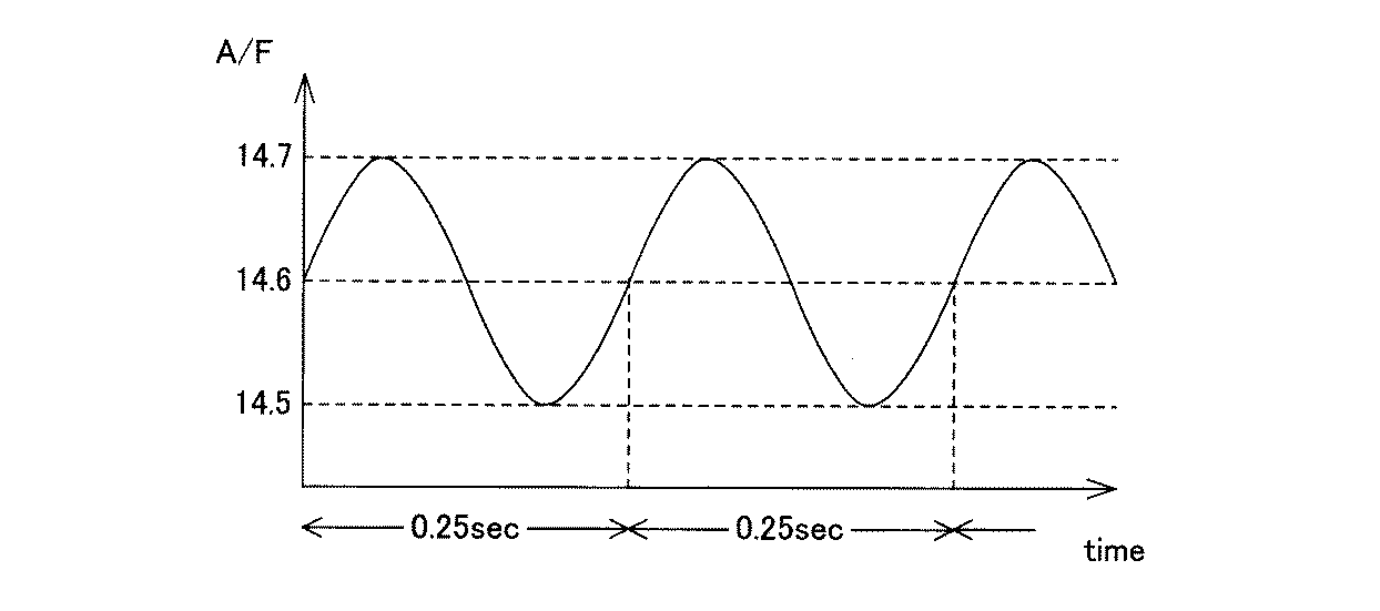
表1に示すように、実施例1、3〜6、8、参考例2、7、9の排ガス浄化用触媒1では、貴金属の平均粒径が非常に小さかった。それに対し、比較例1〜3の排ガス浄化用触媒では、貴金属の平均粒径が非常に大きかった。このことは、実施例1、3〜6、8、参考例2、7、9の排ガス浄化用触媒1では、復元方法の実施により、貴金属の凝集が解消され、触媒性能が回復することを示している。
(ii)浄化性能評価
上記b)の復元方法の実施後、排ガス浄化用触媒1を排気量2Lの直噴エンジンに取り付け、エンジンを運転した。このとき、エンジンの回転トルクを調整し、排ガス浄化用触媒1の入りガス温度が200℃となるようにした。そして、堀場製作所製の排ガス分析計を用いて、エンジン出口(すなわち排ガス浄化用触媒1よりも上流)でのCO濃度C1と、排ガス浄化用触媒1の出口でのCO濃度C2とを、それぞれ測定し、下記式(1)に従って浄化率を算出した。
As shown in Table 1, in the exhaust
(ii) Evaluation of purification performance After carrying out the restoration method of b) above, the exhaust
式(1):浄化率(%)=((C1−C2)/C1)×100
測定結果を表2に示す。
Formula (1): Purification rate (%) = ((C1-C2) / C1) × 100
The measurement results are shown in Table 2.
表2に示すように、実施例1、3〜6、8、参考例2、7、9の排ガス浄化用触媒1は、比較例1〜3よりもCO浄化率が遙かに高かった。
(実施例11)
As shown in Table 2, the exhaust
(Example 11)
a)触媒システム
基本的には前記実施例10のa)と同様にして触媒システム9を構成した。ただし、本実施例11では、エンジン5として、排気量2.2Lのディーゼルエンジン(ターボインタークラーのコモンレール式)を用いた。
a) Catalyst system A catalyst system 9 was basically constructed in the same manner as in Example 10 a). However, in Example 11, a diesel engine with a displacement of 2.2 L (turbo intercler common rail type) was used as the engine 5.
b)触媒の耐久及び復元方法
(i)耐久の実施
前記実施例10のb)(i)と同様に水熱耐久を行った。
(ii)復元方法
その後、触媒システム9を1000時間運転した。このとき、コンピュータ7によりエンジン5の回転トルクを調整することで、排ガス浄化用触媒1の内部温度を300℃に設定し、また、排ガス3の組成を、図4に示すように、基本的にはA/F値を30とするが、10時間に一回の間隔で、長さ20分間の、A/F値が18の状態が現れるように制御した。ここで、A/F値が30の状態が酸化処理工程であり、A/F値が18の状態が還元処理工程である。
c)排ガス浄化用触媒1の評価
前記実施例10のc)と同様にして、貴金属の平均粒径と、浄化率とを測定した。その結果を上記表1及び表2に示す。
b) Durability and restoration method of catalyst
(i) Durability Execution Hydrothermal durability was performed in the same manner as b) (i) of Example 10.
(ii) Restoration method Thereafter, the catalyst system 9 was operated for 1000 hours. At this time, by adjusting the rotational torque of the engine 5 by the computer 7, the internal temperature of the exhaust gas-
c) Evaluation of Exhaust
表1に示すように、実施例1、3〜6、8、参考例2、7、9の排ガス浄化用触媒1では、貴金属の平均粒径が非常に小さかった。それに対し、比較例1〜3の排ガス浄化用触媒では、貴金属の平均粒径が非常に大きかった。このことは、実施例1、3〜6、8、参考例2、7、9の排ガス浄化用触媒1では、復元方法の実施により、貴金属の凝集が解消され、触媒性能が回復することを示している。
As shown in Table 1, in the exhaust
また、表2に示すように、実施例1、3〜6、8、参考例2、7、9の排ガス浄化用触媒1は、比較例1〜3よりもCO浄化率が遙かに高かった。
(実施例12)
Further, as shown in Table 2, the exhaust
(Example 12)
a)触媒システム
基本的には前記実施例10のa)と同様にして触媒システム9を構成した。ただし、本実施例12では、エンジン5として、排気量2.4Lのガソリンエンジンを用いた。
a) Catalyst system A catalyst system 9 was basically constructed in the same manner as in Example 10 a). However, in Example 12, a gasoline engine with a displacement of 2.4 L was used as the engine 5.
b)触媒の耐久及び復元方法
(i)耐久の実施
前記実施例10のb)(i)と同様に水熱耐久を行った。
(ii)復元方法
その後、触媒システム9を50時間運転した。このとき、コンピュータ7によりエンジン5の回転トルクを調整することで、排ガス浄化用触媒1の内部温度を650℃に設定し、また、排ガス3の組成を、図5に示すように、A/F値の中心値が14.6であり、周期4Hz、振幅0.2のサインカーブに従って変動するように制御した。
c)排ガス浄化用触媒1の評価
前記実施例10のc)と同様にして、貴金属の平均粒径と、浄化率とを測定した。その結果を上記表1及び表2に示す。
b) Durability and restoration method of catalyst
(i) Durability Execution Hydrothermal durability was performed in the same manner as b) (i) of Example 10.
(ii) Restoration method Thereafter, the catalyst system 9 was operated for 50 hours. At this time, by adjusting the rotational torque of the engine 5 by the computer 7, the internal temperature of the exhaust gas-
c) Evaluation of Exhaust
表1に示すように、実施例1、3〜6、8、参考例2、7、9の排ガス浄化用触媒1では、貴金属の平均粒径が非常に小さかった。それに対し、比較例1〜3の排ガス浄化用触媒では、貴金属の平均粒径が非常に大きかった。このことは、実施例1、3〜6、8、参考例2、7、9の排ガス浄化用触媒1では、復元方法の実施により、貴金属の凝集が解消され、触媒性能が回復することを示している。
As shown in Table 1, in the exhaust
また、表2に示すように、実施例1、3〜6、8、参考例2、7、9の排ガス浄化用触媒1は、比較例1〜3よりもCO浄化率が遙かに高かった。
(参考例13)
前記実施例10の触媒システム9に対し、前記実施例10のb)(i)と同様の水熱耐久を実施した後、触媒システム9を800時間運転した。このときの運転条件は、基本的には前記実施例10のb)(ii)と同様であるが、排ガス3の組成を、終始リーン状態(A/F値18)とした。
Further, as shown in Table 2, the exhaust
(Reference Example 13)
After the hydrothermal durability similar to b) (i) of Example 10 was performed on the catalyst system 9 of Example 10, the catalyst system 9 was operated for 800 hours. The operating conditions at this time were basically the same as b) (ii) of Example 10, but the composition of the
その後、前記実施例10のc)と同様にして、貴金属の平均粒径と、浄化率とを測定した。その結果を上記表1及び表2に示す。
表1に示すように、参考例13の復元方法では、実施例10の復元方法と比べて、貴金属の平均粒径が大きかった。このことは、参考例13の復元方法では、貴金属が凝集してしまい、触媒機能が回復しないことを示している。
Thereafter, in the same manner as in Example 10 c), the average particle size and the purification rate of the noble metal were measured. The results are shown in Tables 1 and 2 above.
As shown in Table 1, in the restoration method of Reference Example 13, the average particle diameter of the noble metal was larger than that of the restoration method of Example 10. This indicates that in the restoration method of Reference Example 13, noble metals aggregate and the catalytic function does not recover.
また、表2に示すように、参考例13の復元方法よりも、実施例10の復元方法の方が、排ガス浄化用触媒のCO浄化率を回復させる効果が高かった。
(参考例14)
前記実施例11の触媒システム9に対し、前記実施例10のb)(i)と同様の水熱耐久を実施した後、触媒システム9を1000時間運転した。このときの運転条件は、基本的には前記実施例11のb)(ii)と同様であるが、排ガス3の組成を、終始、A/F値30の状態とした。
As shown in Table 2, the restoration method of Example 10 was more effective in restoring the CO purification rate of the exhaust gas purification catalyst than the restoration method of Reference Example 13.
(Reference Example 14)
After the hydrothermal durability similar to b) (i) of Example 10 was performed on the catalyst system 9 of Example 11, the catalyst system 9 was operated for 1000 hours. The operating conditions at this time were basically the same as b) (ii) of Example 11, but the composition of the
その後、前記実施例10のc)と同様にして、貴金属の平均粒径と、浄化率とを測定した。その結果を上記表1及び表2に示す。
表1に示すように、参考例14の復元方法では、実施例11の復元方法と比べて、貴金属の平均粒径が大きかった。このことは、参考例14の復元方法では、貴金属が凝集してしまい、触媒機能が回復しないことを示している。
Thereafter, in the same manner as in Example 10 c), the average particle size and the purification rate of the noble metal were measured. The results are shown in Tables 1 and 2 above.
As shown in Table 1, the average particle diameter of the noble metal was larger in the restoration method of Reference Example 14 than in the restoration method of Example 11. This indicates that in the restoration method of Reference Example 14, noble metals aggregate and the catalytic function does not recover.
また、表2に示すように、参考例14の復元方法よりも、実施例11の復元方法の方が、排ガス浄化用触媒のCO浄化率を回復させる効果が高かった。
(参考例15)
前記実施例12の触媒システム9に対し、前記実施例10のb)(i)と同様の水熱耐久を実施した後、触媒システム9を50時間運転した。このときの運転条件は、基本的には前記実施例12のb)(ii)と同様であるが、排ガス3の組成を、終始リーン状態(A/F値23)とした。
As shown in Table 2, the restoration method of Example 11 was more effective in restoring the CO purification rate of the exhaust gas purification catalyst than the restoration method of Reference Example 14.
(Reference Example 15)
After the hydrothermal durability similar to b) (i) of Example 10 was performed on the catalyst system 9 of Example 12, the catalyst system 9 was operated for 50 hours. The operating conditions at this time were basically the same as b) (ii) of Example 12, but the composition of the
その後、前記実施例10のc)と同様にして、貴金属の平均粒径と、浄化率とを測定した。その結果を上記表1及び表2に示す。
表1に示すように、参考例15の復元方法では、実施例12の復元方法と比べて、貴金属の平均粒径が大きかった。このことは、参考例15の復元方法では、貴金属が凝集してしまい、触媒機能が回復しないことを示している。
Thereafter, in the same manner as in Example 10 c), the average particle size and the purification rate of the noble metal were measured. The results are shown in Tables 1 and 2 above.
As shown in Table 1, the average particle size of the noble metal was larger in the restoration method of Reference Example 15 than in the restoration method of Example 12. This indicates that in the restoration method of Reference Example 15, noble metals aggregate and the catalytic function is not recovered.
また、表2に示すように、参考例15の復元方法よりも、実施例12の復元方法の方が、排ガス浄化用触媒のCO浄化率を回復させる効果が高かった。
尚、本発明は前記実施例になんら限定されるものではなく、本発明を逸脱しない範囲において種々の態様で実施しうることはいうまでもない。
Further, as shown in Table 2, the restoration method of Example 12 was more effective in restoring the CO purification rate of the exhaust gas purification catalyst than the restoration method of Reference Example 15.
Needless to say, the present invention is not limited to the above-described embodiments, and can be implemented in various modes without departing from the scope of the present invention.
1・・・排ガス浄化用触媒
3・・・排ガス
5・・・直噴エンジン
7・・・コンピュータ
9・・・触媒システム
101・・・セラミックハニカム
103・・・触媒コート層
DESCRIPTION OF
Claims (9)
前記酸化物Aに担持された貴金属Bとを含み、
前記貴金属Bと、前記(A−1)との重量比が1:10〜1:300であることを特徴とする排ガス浄化用触媒。 (A-1) Al-Nd inorganic oxide, M g-La inorganic oxide, Zr-Ce-Mg inorganic oxide, one of 及 beauty oxide Nd, and (A-2) Al 2 O 3, An oxide A containing one or more selected from the group consisting of SiO 2 , ZrO 2 , and zeolite;
A noble metal B supported on the oxide A,
The exhaust gas purifying catalyst, wherein a weight ratio of the noble metal B to the (A-1) is 1:10 to 1: 300.
前記排ガス浄化用触媒を、リッチ状態の排ガスにて還元処理する還元処理工程と、を含むことを特徴とする排ガス浄化用触媒の復元方法。 An oxidation treatment step of oxidizing the exhaust gas-purifying catalyst according to any one of claims 1 to 3 with lean exhaust gas;
And a reduction treatment step of reducing the exhaust gas purification catalyst with rich exhaust gas. A method for restoring the exhaust gas purification catalyst.
前記排ガス浄化用触媒に排ガスを供給する供給手段と、
前記排ガスを、リーン状態及びリッチ状態のいずれにも制御可能な制御手段と、
を備えることを特徴とする排ガス浄化用触媒システム。 The exhaust gas-purifying catalyst according to any one of claims 1 to 3 ,
Supply means for supplying exhaust gas to the exhaust gas purification catalyst;
Control means capable of controlling the exhaust gas in either a lean state or a rich state;
An exhaust gas purification catalyst system comprising:
Priority Applications (7)
| Application Number | Priority Date | Filing Date | Title |
|---|---|---|---|
| JP2006117958A JP5582671B2 (en) | 2006-04-21 | 2006-04-21 | Exhaust gas purification catalyst, exhaust gas purification catalyst recovery method, and exhaust gas purification catalyst system |
| EP07742073A EP2011570A4 (en) | 2006-04-21 | 2007-04-20 | Exhaust gas purifying catalyst, method for recovering exhaust gas purifying catalyst, and catalyst system for exhaust gas purification |
| US12/297,660 US8071498B2 (en) | 2006-04-21 | 2007-04-20 | Exhaust gas purifying catalyst, method for recovering exhaust gas purifying catalyst, and catalyst system for exhaust gas purification |
| KR1020087023989A KR100995458B1 (en) | 2006-04-21 | 2007-04-20 | Exhaust gas purification catalyst, Exhaust gas purification catalyst restoration method, and exhaust gas purification catalyst system |
| CN2007800127049A CN101421037B (en) | 2006-04-21 | 2007-04-20 | Exhaust gas purifying catalyst, method for recovering exhaust gas purifying catalyst, and catalyst system for exhaust gas purification |
| PCT/JP2007/058638 WO2007123205A1 (en) | 2006-04-21 | 2007-04-20 | Exhaust gas purifying catalyst, method for recovering exhaust gas purifying catalyst, and catalyst system for exhaust gas purification |
| CN2011101220522A CN102198370B (en) | 2006-04-21 | 2007-04-20 | Catalyst system for gas exhaust purification |
Applications Claiming Priority (1)
| Application Number | Priority Date | Filing Date | Title |
|---|---|---|---|
| JP2006117958A JP5582671B2 (en) | 2006-04-21 | 2006-04-21 | Exhaust gas purification catalyst, exhaust gas purification catalyst recovery method, and exhaust gas purification catalyst system |
Publications (3)
| Publication Number | Publication Date |
|---|---|
| JP2007289812A JP2007289812A (en) | 2007-11-08 |
| JP2007289812A5 JP2007289812A5 (en) | 2008-11-13 |
| JP5582671B2 true JP5582671B2 (en) | 2014-09-03 |
Family
ID=38625105
Family Applications (1)
| Application Number | Title | Priority Date | Filing Date |
|---|---|---|---|
| JP2006117958A Expired - Fee Related JP5582671B2 (en) | 2006-04-21 | 2006-04-21 | Exhaust gas purification catalyst, exhaust gas purification catalyst recovery method, and exhaust gas purification catalyst system |
Country Status (6)
| Country | Link |
|---|---|
| US (1) | US8071498B2 (en) |
| EP (1) | EP2011570A4 (en) |
| JP (1) | JP5582671B2 (en) |
| KR (1) | KR100995458B1 (en) |
| CN (2) | CN102198370B (en) |
| WO (1) | WO2007123205A1 (en) |
Families Citing this family (11)
| Publication number | Priority date | Publication date | Assignee | Title |
|---|---|---|---|---|
| JP5482179B2 (en) † | 2008-12-22 | 2014-04-23 | 東ソー株式会社 | Chabazite-type zeolite and method for producing the same |
| BR112012030016B8 (en) | 2010-05-24 | 2021-05-18 | Siluria Technologies Inc | process for preparing ethylene from methane and method for preparing an ethylene downstream product |
| WO2012162526A2 (en) | 2011-05-24 | 2012-11-29 | Siluria Technologies, Inc. | Catalysts for petrochemical catalysis |
| EP2785458A2 (en) | 2011-11-29 | 2014-10-08 | Siluria Technologies, Inc. | Nanowire catalysts and methods for their use and preparation |
| US9446397B2 (en) | 2012-02-03 | 2016-09-20 | Siluria Technologies, Inc. | Method for isolation of nanomaterials |
| EP2855011A2 (en) | 2012-05-24 | 2015-04-08 | Siluria Technologies, Inc. | Catalytic forms and formulations |
| EP2969184A4 (en) | 2013-03-15 | 2016-12-21 | Siluria Technologies Inc | Catalysts for petrochemical catalysis |
| EP3086872B1 (en) * | 2013-12-23 | 2020-07-15 | Rhodia Operations | Inorganic composte oxide material, preparation and use exhaust gas purification catalysts |
| CA2947483C (en) | 2014-05-02 | 2023-08-01 | Siluria Technologies, Inc. | Heterogeneous catalysts |
| CA2960555A1 (en) | 2014-09-17 | 2016-03-24 | Siluria Technologies, Inc. | Catalysts for oxidative coupling of methane and oxidative dehydrogenation of ethane |
| WO2017191434A1 (en) * | 2016-05-05 | 2017-11-09 | Johnson Matthey Public Limited Company | NOx ADSORBER CATALYST |
Family Cites Families (31)
| Publication number | Priority date | Publication date | Assignee | Title |
|---|---|---|---|---|
| JPH08144748A (en) | 1994-11-22 | 1996-06-04 | Nissan Motor Co Ltd | Exhaust emission control device for internal combustion engine |
| US6165429A (en) * | 1997-01-10 | 2000-12-26 | Toyota Jidosha Kabushiki Kaisha | Exhaust gas purifying catalyst and exhaust gas purifying method |
| EP0892159A3 (en) * | 1997-07-17 | 2000-04-26 | Hitachi, Ltd. | Exhaust gas cleaning apparatus and method for internal combustion engine |
| JP3688871B2 (en) * | 1997-11-20 | 2005-08-31 | ダイハツ工業株式会社 | Exhaust gas purification catalyst |
| JP3741303B2 (en) | 1997-12-08 | 2006-02-01 | トヨタ自動車株式会社 | Exhaust gas purification catalyst |
| JPH11221467A (en) * | 1998-02-05 | 1999-08-17 | Toyota Motor Corp | Catalyst for purifying exhaust gas |
| DE19813655C2 (en) * | 1998-03-27 | 2000-04-27 | Degussa | Storage material for sulfur oxides, process for its production and use |
| KR19990083414A (en) * | 1998-04-27 | 1999-11-25 | 카와무라 히데오 | A Purifying system for exhaust gas and controlling method thereof |
| JP4309978B2 (en) * | 1998-08-25 | 2009-08-05 | 株式会社日立製作所 | Exhaust gas purification method, exhaust gas purification device, and exhaust gas purification catalyst |
| JP3673816B2 (en) * | 1999-03-15 | 2005-07-20 | 株式会社豊田中央研究所 | Exhaust gas purification catalyst and exhaust gas purification method |
| JP2001000840A (en) * | 1999-06-21 | 2001-01-09 | Toyota Central Res & Dev Lab Inc | Exhaust gas purification equipment |
| JP3724708B2 (en) * | 1999-11-26 | 2005-12-07 | 日産自動車株式会社 | Exhaust gas purification catalyst |
| JP4590733B2 (en) * | 2000-02-22 | 2010-12-01 | マツダ株式会社 | Exhaust gas purification catalyst and exhaust gas purification method using the catalyst |
| US6468484B1 (en) * | 2000-06-29 | 2002-10-22 | Delphi Technologies, Inc. | NO2 abatement composition with enhanced sulfur resistance |
| JP2002115534A (en) * | 2000-10-12 | 2002-04-19 | Hitachi Ltd | Exhaust emission control device for internal combustion engine |
| JP4144174B2 (en) * | 2000-10-25 | 2008-09-03 | トヨタ自動車株式会社 | Exhaust gas purification device |
| JP2002133170A (en) * | 2000-10-26 | 2002-05-10 | Sony Corp | Idea investing device, idea applying device using it, and method for them |
| JP2002166170A (en) * | 2000-11-29 | 2002-06-11 | Nissan Motor Co Ltd | Exhaust gas cleaning catalyst and method for preparing the same |
| JP2002239383A (en) * | 2001-02-16 | 2002-08-27 | Toyota Central Res & Dev Lab Inc | NOx storage reduction catalyst and method of using the same |
| US6866834B2 (en) * | 2001-03-12 | 2005-03-15 | Nissan Motor Co., Ltd. | NOx reduction catalyst and NOx reduction system |
| JP4019351B2 (en) * | 2001-03-12 | 2007-12-12 | 日産自動車株式会社 | NOx purification catalyst and NOx purification system |
| JP3985054B2 (en) | 2002-02-22 | 2007-10-03 | マツダ株式会社 | Exhaust gas purification catalyst |
| JP4254208B2 (en) * | 2002-11-20 | 2009-04-15 | 株式会社日立製作所 | Internal combustion engine exhaust gas purification device, purification method and catalyst |
| JP2004216223A (en) * | 2003-01-10 | 2004-08-05 | Toyota Central Res & Dev Lab Inc | NOx storage reduction catalyst |
| JP2004216224A (en) * | 2003-01-10 | 2004-08-05 | Toyota Central Res & Dev Lab Inc | NOx storage reduction catalyst |
| JP3795871B2 (en) * | 2003-03-20 | 2006-07-12 | 株式会社キャタラー | Exhaust gas purification catalyst system |
| JP2006043637A (en) * | 2004-08-06 | 2006-02-16 | Toyota Motor Corp | Exhaust gas purification catalyst |
| JP4556587B2 (en) * | 2004-09-22 | 2010-10-06 | マツダ株式会社 | Exhaust gas purification device |
| CN1724154A (en) | 2005-06-10 | 2006-01-25 | 陈昭萍 | Catalyst for purifying exhaust gas of natural gas engine and preparation method thereof |
| JP4833605B2 (en) * | 2005-07-21 | 2011-12-07 | 株式会社キャタラー | Exhaust gas purification catalyst |
| JP4435750B2 (en) * | 2006-03-30 | 2010-03-24 | 株式会社キャタラー | Exhaust gas purification catalyst and method for producing the same |
-
2006
- 2006-04-21 JP JP2006117958A patent/JP5582671B2/en not_active Expired - Fee Related
-
2007
- 2007-04-20 WO PCT/JP2007/058638 patent/WO2007123205A1/en active Application Filing
- 2007-04-20 CN CN2011101220522A patent/CN102198370B/en not_active Expired - Fee Related
- 2007-04-20 EP EP07742073A patent/EP2011570A4/en not_active Withdrawn
- 2007-04-20 US US12/297,660 patent/US8071498B2/en not_active Expired - Fee Related
- 2007-04-20 CN CN2007800127049A patent/CN101421037B/en not_active Expired - Fee Related
- 2007-04-20 KR KR1020087023989A patent/KR100995458B1/en not_active IP Right Cessation
Also Published As
| Publication number | Publication date |
|---|---|
| WO2007123205A1 (en) | 2007-11-01 |
| CN102198370B (en) | 2013-08-28 |
| CN101421037A (en) | 2009-04-29 |
| CN101421037B (en) | 2012-06-06 |
| KR100995458B1 (en) | 2010-11-18 |
| EP2011570A4 (en) | 2012-07-25 |
| US20090099005A1 (en) | 2009-04-16 |
| EP2011570A1 (en) | 2009-01-07 |
| JP2007289812A (en) | 2007-11-08 |
| CN102198370A (en) | 2011-09-28 |
| US8071498B2 (en) | 2011-12-06 |
| KR20090003295A (en) | 2009-01-09 |
Similar Documents
| Publication | Publication Date | Title |
|---|---|---|
| JP5582671B2 (en) | Exhaust gas purification catalyst, exhaust gas purification catalyst recovery method, and exhaust gas purification catalyst system | |
| JP5373255B2 (en) | NOx reduction catalyst, NOx reduction catalyst system, and NOx reduction method | |
| JP5422087B2 (en) | Low noble metal supported three way catalyst | |
| WO2012128297A1 (en) | Catalyst for exhaust gas purification, method for producing same, and exhaust gas purification method using same | |
| JP5526502B2 (en) | Exhaust gas purification catalyst and method for producing the same | |
| CN101146612A (en) | Catalyst carrier powder and exhaust gas purification catalyst | |
| JP5876436B2 (en) | Exhaust gas purification catalyst and exhaust gas purification method | |
| JP4265626B2 (en) | Catalyst carrier particles, method for producing the same, and exhaust gas purification catalyst | |
| JP2004074138A (en) | Exhaust gas purification catalyst and exhaust gas purification method | |
| JP5754691B2 (en) | Exhaust gas purification three-way catalyst | |
| WO2011004689A1 (en) | Particulate combustion catalyst | |
| JP5078125B2 (en) | Exhaust gas purification catalyst and regeneration method thereof | |
| JP2005254047A (en) | Exhaust gas purification catalyst, metal oxide particles and production method thereof | |
| KR102577494B1 (en) | Platinum-containing catalysts for combustion engines | |
| JP4794834B2 (en) | Exhaust gas purification catalyst | |
| JP3766568B2 (en) | Exhaust gas purification catalyst and exhaust gas purification method | |
| JP4775953B2 (en) | Exhaust gas purification catalyst and regeneration method thereof | |
| JP2014124631A (en) | Exhaust gas purification catalyst and exhaust gas purification method | |
| JP4730947B2 (en) | Method for regenerating exhaust gas purification catalyst | |
| JP2022553892A (en) | diesel oxidation catalyst | |
| JP4775954B2 (en) | Exhaust gas purification catalyst and regeneration method thereof | |
| JP2007105632A (en) | Exhaust gas cleaning catalyst | |
| JP2002177788A (en) | Exhaust gas cleaning catalyst and its manufacturing method | |
| JP3310711B2 (en) | Exhaust gas treatment device | |
| JP2012135742A (en) | Particulate combustion catalyst, method for production thereof, particulate filter, and method for producing the same |
Legal Events
| Date | Code | Title | Description |
|---|---|---|---|
| A521 | Written amendment |
Free format text: JAPANESE INTERMEDIATE CODE: A523 Effective date: 20080926 |
|
| A621 | Written request for application examination |
Free format text: JAPANESE INTERMEDIATE CODE: A621 Effective date: 20090223 |
|
| A131 | Notification of reasons for refusal |
Free format text: JAPANESE INTERMEDIATE CODE: A131 Effective date: 20120626 |
|
| A521 | Written amendment |
Free format text: JAPANESE INTERMEDIATE CODE: A523 Effective date: 20120710 |
|
| A131 | Notification of reasons for refusal |
Free format text: JAPANESE INTERMEDIATE CODE: A131 Effective date: 20130507 |
|
| A521 | Written amendment |
Free format text: JAPANESE INTERMEDIATE CODE: A523 Effective date: 20130527 |
|
| A131 | Notification of reasons for refusal |
Free format text: JAPANESE INTERMEDIATE CODE: A131 Effective date: 20140311 |
|
| A521 | Written amendment |
Free format text: JAPANESE INTERMEDIATE CODE: A523 Effective date: 20140424 |
|
| TRDD | Decision of grant or rejection written | ||
| A01 | Written decision to grant a patent or to grant a registration (utility model) |
Free format text: JAPANESE INTERMEDIATE CODE: A01 Effective date: 20140624 |
|
| A61 | First payment of annual fees (during grant procedure) |
Free format text: JAPANESE INTERMEDIATE CODE: A61 Effective date: 20140715 |
|
| R150 | Certificate of patent or registration of utility model |
Ref document number: 5582671 Country of ref document: JP Free format text: JAPANESE INTERMEDIATE CODE: R150 |
|
| R250 | Receipt of annual fees |
Free format text: JAPANESE INTERMEDIATE CODE: R250 |
|
| LAPS | Cancellation because of no payment of annual fees |