JP5268364B2 - 距離測定システムを有する磁気駆動システムを備えたスライドドア - Google Patents
距離測定システムを有する磁気駆動システムを備えたスライドドア Download PDFInfo
- Publication number
- JP5268364B2 JP5268364B2 JP2007550700A JP2007550700A JP5268364B2 JP 5268364 B2 JP5268364 B2 JP 5268364B2 JP 2007550700 A JP2007550700 A JP 2007550700A JP 2007550700 A JP2007550700 A JP 2007550700A JP 5268364 B2 JP5268364 B2 JP 5268364B2
- Authority
- JP
- Japan
- Prior art keywords
- sliding door
- magnet
- magnetic
- individual
- position sensor
- Prior art date
- Legal status (The legal status is an assumption and is not a legal conclusion. Google has not performed a legal analysis and makes no representation as to the accuracy of the status listed.)
- Expired - Fee Related
Links
- 230000005291 magnetic effect Effects 0.000 title claims description 94
- 238000005259 measurement Methods 0.000 claims description 35
- 230000009471 action Effects 0.000 claims description 8
- 239000000696 magnetic material Substances 0.000 claims description 7
- 230000008878 coupling Effects 0.000 claims description 3
- 238000010168 coupling process Methods 0.000 claims description 3
- 238000005859 coupling reaction Methods 0.000 claims description 3
- 230000003993 interaction Effects 0.000 claims description 2
- 230000005389 magnetism Effects 0.000 claims description 2
- 229910052761 rare earth metal Inorganic materials 0.000 claims 2
- 150000002910 rare earth metals Chemical class 0.000 claims 2
- 238000000465 moulding Methods 0.000 description 16
- 238000010586 diagram Methods 0.000 description 10
- 230000008901 benefit Effects 0.000 description 8
- 238000012546 transfer Methods 0.000 description 7
- XEEYBQQBJWHFJM-UHFFFAOYSA-N Iron Chemical compound [Fe] XEEYBQQBJWHFJM-UHFFFAOYSA-N 0.000 description 6
- 238000010587 phase diagram Methods 0.000 description 6
- 238000001514 detection method Methods 0.000 description 5
- 229910000831 Steel Inorganic materials 0.000 description 4
- 239000003302 ferromagnetic material Substances 0.000 description 4
- 238000004519 manufacturing process Methods 0.000 description 4
- 239000010959 steel Substances 0.000 description 4
- 230000008859 change Effects 0.000 description 3
- 230000000694 effects Effects 0.000 description 3
- 238000011156 evaluation Methods 0.000 description 3
- 229910052742 iron Inorganic materials 0.000 description 3
- 239000000463 material Substances 0.000 description 3
- 230000033228 biological regulation Effects 0.000 description 2
- 230000000903 blocking effect Effects 0.000 description 2
- 230000001419 dependent effect Effects 0.000 description 2
- 230000005284 excitation Effects 0.000 description 2
- 238000012423 maintenance Methods 0.000 description 2
- 238000000691 measurement method Methods 0.000 description 2
- 238000000034 method Methods 0.000 description 2
- 239000007787 solid Substances 0.000 description 2
- 239000000725 suspension Substances 0.000 description 2
- 229910000859 α-Fe Inorganic materials 0.000 description 2
- QJVKUMXDEUEQLH-UHFFFAOYSA-N [B].[Fe].[Nd] Chemical compound [B].[Fe].[Nd] QJVKUMXDEUEQLH-UHFFFAOYSA-N 0.000 description 1
- 230000001133 acceleration Effects 0.000 description 1
- 239000013543 active substance Substances 0.000 description 1
- XAGFODPZIPBFFR-UHFFFAOYSA-N aluminium Chemical compound [Al] XAGFODPZIPBFFR-UHFFFAOYSA-N 0.000 description 1
- 229910052782 aluminium Inorganic materials 0.000 description 1
- 238000003491 array Methods 0.000 description 1
- KPLQYGBQNPPQGA-UHFFFAOYSA-N cobalt samarium Chemical compound [Co].[Sm] KPLQYGBQNPPQGA-UHFFFAOYSA-N 0.000 description 1
- 239000004020 conductor Substances 0.000 description 1
- 238000011161 development Methods 0.000 description 1
- 230000005684 electric field Effects 0.000 description 1
- 230000002708 enhancing effect Effects 0.000 description 1
- 230000006698 induction Effects 0.000 description 1
- 230000001788 irregular Effects 0.000 description 1
- 230000005426 magnetic field effect Effects 0.000 description 1
- 229910001172 neodymium magnet Inorganic materials 0.000 description 1
- 230000000737 periodic effect Effects 0.000 description 1
- 238000012545 processing Methods 0.000 description 1
- 230000001141 propulsive effect Effects 0.000 description 1
- 238000010992 reflux Methods 0.000 description 1
- 230000000717 retained effect Effects 0.000 description 1
- 229910000938 samarium–cobalt magnet Inorganic materials 0.000 description 1
- 229920006395 saturated elastomer Polymers 0.000 description 1
- 230000006641 stabilisation Effects 0.000 description 1
- 238000011105 stabilization Methods 0.000 description 1
- 230000001360 synchronised effect Effects 0.000 description 1
Images


Classifications
-
- H—ELECTRICITY
- H02—GENERATION; CONVERSION OR DISTRIBUTION OF ELECTRIC POWER
- H02K—DYNAMO-ELECTRIC MACHINES
- H02K41/00—Propulsion systems in which a rigid body is moved along a path due to dynamo-electric interaction between the body and a magnetic field travelling along the path
- H02K41/02—Linear motors; Sectional motors
- H02K41/03—Synchronous motors; Motors moving step by step; Reluctance motors
- H02K41/031—Synchronous motors; Motors moving step by step; Reluctance motors of the permanent magnet type
-
- E—FIXED CONSTRUCTIONS
- E05—LOCKS; KEYS; WINDOW OR DOOR FITTINGS; SAFES
- E05F—DEVICES FOR MOVING WINGS INTO OPEN OR CLOSED POSITION; CHECKS FOR WINGS; WING FITTINGS NOT OTHERWISE PROVIDED FOR, CONCERNED WITH THE FUNCTIONING OF THE WING
- E05F15/00—Power-operated mechanisms for wings
- E05F15/60—Power-operated mechanisms for wings using electrical actuators
-
- H—ELECTRICITY
- H02—GENERATION; CONVERSION OR DISTRIBUTION OF ELECTRIC POWER
- H02K—DYNAMO-ELECTRIC MACHINES
- H02K11/00—Structural association of dynamo-electric machines with electric components or with devices for shielding, monitoring or protection
- H02K11/20—Structural association of dynamo-electric machines with electric components or with devices for shielding, monitoring or protection for measuring, monitoring, testing, protecting or switching
- H02K11/21—Devices for sensing speed or position, or actuated thereby
- H02K11/215—Magnetic effect devices, e.g. Hall-effect or magneto-resistive elements
-
- H—ELECTRICITY
- H02—GENERATION; CONVERSION OR DISTRIBUTION OF ELECTRIC POWER
- H02N—ELECTRIC MACHINES NOT OTHERWISE PROVIDED FOR
- H02N15/00—Holding or levitation devices using magnetic attraction or repulsion, not otherwise provided for
-
- H—ELECTRICITY
- H02—GENERATION; CONVERSION OR DISTRIBUTION OF ELECTRIC POWER
- H02P—CONTROL OR REGULATION OF ELECTRIC MOTORS, ELECTRIC GENERATORS OR DYNAMO-ELECTRIC CONVERTERS; CONTROLLING TRANSFORMERS, REACTORS OR CHOKE COILS
- H02P25/00—Arrangements or methods for the control of AC motors characterised by the kind of AC motor or by structural details
- H02P25/02—Arrangements or methods for the control of AC motors characterised by the kind of AC motor or by structural details characterised by the kind of motor
- H02P25/06—Linear motors
-
- E—FIXED CONSTRUCTIONS
- E05—LOCKS; KEYS; WINDOW OR DOOR FITTINGS; SAFES
- E05D—HINGES OR SUSPENSION DEVICES FOR DOORS, WINDOWS OR WINGS
- E05D15/00—Suspension arrangements for wings
- E05D15/06—Suspension arrangements for wings for wings sliding horizontally more or less in their own plane
- E05D15/0621—Details, e.g. suspension or supporting guides
- E05D2015/0695—Magnetic suspension or supporting means
-
- E—FIXED CONSTRUCTIONS
- E05—LOCKS; KEYS; WINDOW OR DOOR FITTINGS; SAFES
- E05Y—INDEXING SCHEME ASSOCIATED WITH SUBCLASSES E05D AND E05F, RELATING TO CONSTRUCTION ELEMENTS, ELECTRIC CONTROL, POWER SUPPLY, POWER SIGNAL OR TRANSMISSION, USER INTERFACES, MOUNTING OR COUPLING, DETAILS, ACCESSORIES, AUXILIARY OPERATIONS NOT OTHERWISE PROVIDED FOR, APPLICATION THEREOF
- E05Y2600/00—Mounting or coupling arrangements for elements provided for in this subclass
- E05Y2600/40—Mounting location; Visibility of the elements
- E05Y2600/454—Mounting location; Visibility of the elements in or on the motor
-
- E—FIXED CONSTRUCTIONS
- E05—LOCKS; KEYS; WINDOW OR DOOR FITTINGS; SAFES
- E05Y—INDEXING SCHEME ASSOCIATED WITH SUBCLASSES E05D AND E05F, RELATING TO CONSTRUCTION ELEMENTS, ELECTRIC CONTROL, POWER SUPPLY, POWER SIGNAL OR TRANSMISSION, USER INTERFACES, MOUNTING OR COUPLING, DETAILS, ACCESSORIES, AUXILIARY OPERATIONS NOT OTHERWISE PROVIDED FOR, APPLICATION THEREOF
- E05Y2900/00—Application of doors, windows, wings or fittings thereof
- E05Y2900/10—Application of doors, windows, wings or fittings thereof for buildings or parts thereof
- E05Y2900/13—Type of wing
- E05Y2900/132—Doors
-
- H—ELECTRICITY
- H02—GENERATION; CONVERSION OR DISTRIBUTION OF ELECTRIC POWER
- H02K—DYNAMO-ELECTRIC MACHINES
- H02K2213/00—Specific aspects, not otherwise provided for and not covered by codes H02K2201/00 - H02K2211/00
- H02K2213/03—Machines characterised by numerical values, ranges, mathematical expressions or similar information
Landscapes
- Engineering & Computer Science (AREA)
- Power Engineering (AREA)
- Chemical & Material Sciences (AREA)
- Combustion & Propulsion (AREA)
- Microelectronics & Electronic Packaging (AREA)
- Physics & Mathematics (AREA)
- Electromagnetism (AREA)
- Power-Operated Mechanisms For Wings (AREA)
- Linear Motors (AREA)
Description
1.回転子位置が検出され、これによって相電圧が回転子位置に依存して、固定子のコミュテーションのために、連続的なモータ推進が生じるように変えられる。有利には電圧は正弦状に変調される。
2.ドア速度調整のために走行距離が測定される。
3.ドア速度調整および障害物検出のために、ドア速度が位置信号から導出される。
4.最終位置識別および可能な走行距離の測定が基準走行において行われる。
1.コスト的利点。なぜなら、磁気スケールが既に設けられており、ホールセンサは比較的廉価だからである。
2.回転子位置検索を省くことができる。なぜなら、ホールセンサの取り付け位置によって、リニアモータの回転子位置の測定信号と固定子のコイル位置との間に固定された関係が生じているからである。固定された形状的な対応関係によってさらに、外部システムのときのような位置関係の喪失が生じない。
1.回転子上の磁石列の長さは構造上、ドアの走行距離よりも短いので、図22に示されているように、回転子は測定領域から出てしまう。
2.磁石列の個々の磁石の最大磁界強度は、永久磁石の間の幾何学的形状許容誤差の故に、異なった材料特性および明確な相違がある質を有している。従って評価は困難であり、測定結果は正確ではない。ホールセンサ16の、図21に示された出力信号21は例えば、第3および第4の極大値の間で振幅差Dを示している。この振幅差は上述の作用によって生じたものである。
3.回転子位置に依存した測定値経過は、磁石配置、センサ選択およびセンサ位置に依存する。位置センサの出力信号は通常は、図21に示されたホールセンサ16の出力信号S1から明確に分かるように、正弦関数にのみ類似している。
4.正弦に類似した、ホールセンサ16の結果関数の急峻な部分のみが十分な精度でアナログ評価される。関数経過の僅かな上昇、極大および極小の領域においては、アナログ関数評価は可能ではない。これは図21に示された、ホールセンサ16の出力信号S1から明らかである。
5.オン状態にされたモータでは、磁石列1の個別磁石の磁界は、駆動コイルの磁界と重畳する。従って磁石列1の個別磁石の磁界が妨害され、測定結果は誤ったものになってしまう。
図1は、本発明で基本的に使用されている、組み合わされた搬送および駆動システムの縦断面図であり、
図2は、図1に示された、組み合わされた搬送および駆動システムのリニア駆動ユニットのコイルの電気的な接続を示す図であり、
図3は、図2に示され、本発明に相応して使用される駆動システムの接続されたコイルでの電圧経過特性の第1の可能性を説明するダイヤグラムであり、
図4は、図2に示された、本発明に相応して使用される駆動システムの接続されたコイルでの電圧経過特性の第2の可能性を説明するダイヤグラムであり、
図5は、図2に示された、本発明に相応して使用される駆動システムの接続されたコイルでの電圧経過特性の第3の可能性を説明するダイヤグラムであり、
図6は、本発明の有利な実施形態に従ったスライドドアの横断面図であり、
図7は、本発明の位置センサの配置構成の第1の有利な実施形態であり、
図8は、本発明の位置センサの配置構成の第2の有利な実施形態であり、
図9は、本発明の位置センサの配置構成の第3の有利な実施形態であり、
図10は、本発明の位置センサの配置構成の第4の有利な実施形態であり、
図11は、本発明の位置センサの出力信号であり、
図12は、本発明の位置センサの2つの個別センサの出力信号と、2つの個別センサから成る位置センサの結果として生じる信号であり、
図13は、本発明の位置センサの3つの個別センサの出力信号と、3つの個別センサから成る位置センサの結果として生じる信号であり、
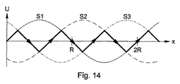
図14は、本発明の位置センサの3つの個別センサの出力信号と、3つの個別センサから成る位置センサの結果として生じる信号であり、
図15は、本発明の位置センサの配置構成の第5の有利な実施形態であり、
図16は、本発明の位置センサの配置構成の第6の有利な実施形態であり、
図17は、本発明の第1の構成に従った、磁気伝導性ヨーク体の使用であり、
図18は、本発明の第2の構成に従った、磁気伝導性ヨーク体の使用であり、
図19は、本発明の遮蔽部材の使用であり、
図20は、従来技術に従った位置センサの配置構成の第1の実施形態であり、
図21は、従来技術に従った位置センサの出力信号であり、
図22は、従来技術に従った位置センサの配置構成の第2の実施形態である。
Claims (21)
- 少なくとも1つのドア扉(5)用の磁気駆動システムを有するスライドドアであって、
前記磁気駆動システムは駆動方向に配置された磁石列(1)を有しており、該磁石列の磁性は自身の長手方向において、特定の間隔で符号を変え、
さらに前記磁気駆動システムは、当該磁石列(1)と接続された搬送キャリッジ(4)を有しており、当該搬送キャリッジに前記ドア扉(5)が固定されており、
さらに前記磁気駆動システムは複数の個別コイル(2)とコイル芯(3)とから成るコイル装置を有しており、該コイル装置は、前記個別コイル(2)が駆動制御された時に、前記磁石列(1)との相互作用を生じさせ、該相互作用が推力を生起させ、
さらに前記磁気駆動システムは、第1の感磁式位置センサ(16)を有する距離測定システムを有しており、該距離測定システムは磁石列(1)とともに磁気スケールとして作動する形式のものにおいて、
前記距離測定システムは前記第1の感磁式位置センサ(16)に近接した第2の感磁式位置センサ(17)を有しており、該第2の感磁式位置センサと前記第1の位置センサ(16)との間の間隔(A)は、前記磁石列(1)の長さ(L)と、スライドドアの走行区間(V)の長さとの間の差よりも長く、前記磁石列(1)の長さ(L)よりも短く、
スライドドアの走行区間(V)が前記第1の位置センサ(16)の測定領域と前記第2の位置センサ(17)の測定領域とに分割されるように前記第1および第2の位置センサ(16、17)が配置されている、
ことを特徴とする、磁気駆動システムを有するスライドドア。 - 前記第1の位置センサ(16)と前記第2の位置センサ(17)の間の間隔(A)は少なくとも、前記磁石列(1)の2つの個別磁石の間の磁石磁性間隔(R)ぶんだけ、前記磁石列(1)の長さ(L)とスライドドアの走行区間(V)の長さとの間の差よりも長く、少なくとも、前記磁石列(1)の2つの個別磁石の間の磁石磁性間隔(R)ぶんだけ、前記磁石列(1)の長さ(L)よりも短い、請求項1記載のスライドドア。
- 前記第1の位置センサ(16)と第2の位置センサ(17)との間の間隔(A)は、前記磁石列(1)の2つの個別磁石の間の磁石磁性間隔(R)の倍数であり、同時に2つの個別コイル(2)の間のコイル間隔(SP)の倍数である、請求項1または2記載のスライドドア。
- 前記第1及び第2感磁式位置センサ(16、17)はホールセンサおよび/または磁気抵抗性センサである、請求項1から3までのいずれか1項記載のスライドドア。
- 前記第1及び第2感磁式位置センサ(16、17)はそれぞれ、複数の感磁式個別センサ(16a、16b、16c、17a、17b、17c)から成る、請求項1から4までのいずれか1項記載のスライドドア。
- 各感磁式位置センサ(16、17)の前記感磁式個別センサ(16a、16b、16c、17a、17b、17c)は相互に固定間隔(S)を有しており、常に前記個別センサ(16a、16b、16c、17a、17b、17c)によって出力された測定信号の少なくとも1つが最も急峻な信号部分を示す、請求項5記載のスライドドア。
- 各感磁式位置センサ(16、17)の感磁式個別センサ(16a、16b、16c、17a、17b、17c)の数は前記駆動システムの電気的位相の数に等しい、請求項5または6記載のスライドドア。
- 前記両感磁式位置センサ(16、17)の感磁式個別センサ(16a、16b、16c、17a、17b、17c)は相互に固定間隔(S)を有しており、当該間隔は磁石列(1)の2つの個部磁石の間の磁石磁性間隔(R)と前記位置センサ(16、17)内で使用されている個別センサ(16a、16b、16c、17a、17b、17c)の数との商またはその倍数に等しい、請求項5から7までのいずれか1項記載のスライドドア。
- 前記第1及び第2感磁式位置センサ(16、17)は磁界強度に依存せず、磁界方向のみ測定する、請求項1から8までのいずれか1項記載のスライドドア。
- 前記第1及び第2感磁式位置センサ(16、17)を介して前記磁石列(1)の個別磁石の磁界結合を改善する磁気伝導性ヨーク体(35)を有している、請求項1から9までのいずれか1項記載のスライドドア。
- 前記磁気伝導性ヨーク体(35)は軟磁性材料から成る、請求項10記載のスライドドア。
- 遮蔽部材を有しており、当該遮蔽部材は前記両感磁式位置センサ(16、17)およびその個別センサ(16a、16b、16c、17a、17b、17c)を包囲し、前記両感磁式位置センサ(16、17)に影響する前記個別コイル(2)の散乱領域の妨害作用が低減される、請求項1から11までのいずれか1項記載のスライドドア。
- 前記遮蔽部材は軟磁性材料から成る、請求項12記載のスライドドア。
- 前記個別コイル(2)は1つの列の中に配置されており、前記列は前記両感磁式位置センサ(16、17)によって中断されている、請求項1から13までのいずれか1項記載のスライドドア。
- 前記個別コイル(2)のコイル装置は、前記第1及び第2感磁式位置センサ(16、17)から間隔を伴って、感磁式位置センサ(16、17)の間に配置されている、請求項1から14までのいずれか1項記載のスライドドア。
- 前記磁石列(1)と接続されたローラ装置(7、8)を有しており、
当該ローラ装置はドア扉(5)に関して搬送機能を満たし、磁石列(1)とコイル芯(3)との間に特定のギャップ状間隔(a)を確保する、請求項1から15までのいずれか1項記載のスライドドア。 - 前記磁石列(1)は支持方向(z)に対して平行に磁性付けされ、駆動方向(x)に対して横方向に磁性付けされている、請求項1から16までのいずれか1項記載のスライドドア。
- 前記磁石列(1)は複数の高エネルギー磁石から成る、請求項1から17までのいずれか1項記載のスライドドア。
- 前記複数の高エネルギー磁石は希土類高エネルギー磁石である、請求項18記載のスライドドア。
- 前記複数の希土類高エネルギー磁石は、NeFeBまたはSm2COタイプである、請求項19記載のスライドドア。
- 前記スライドドアは湾曲スライドドアまたは水平スライド壁として構成されている、請求項1から20までのいずれか1項記載のスライドドア。
Applications Claiming Priority (3)
| Application Number | Priority Date | Filing Date | Title |
|---|---|---|---|
| DE102005002046.1 | 2005-01-14 | ||
| DE102005002046A DE102005002046B4 (de) | 2005-01-14 | 2005-01-14 | Schiebetür mit einem magnetischen Antriebssystem mit einem Wegmesssystem |
| PCT/EP2005/013396 WO2006074783A1 (de) | 2005-01-14 | 2005-12-13 | Schiebetür mit einem magnetischen antriebssystem mit einem wegmesssystem |
Publications (3)
| Publication Number | Publication Date |
|---|---|
| JP2008527217A JP2008527217A (ja) | 2008-07-24 |
| JP2008527217A5 JP2008527217A5 (ja) | 2012-10-11 |
| JP5268364B2 true JP5268364B2 (ja) | 2013-08-21 |
Family
ID=36283762
Family Applications (1)
| Application Number | Title | Priority Date | Filing Date |
|---|---|---|---|
| JP2007550700A Expired - Fee Related JP5268364B2 (ja) | 2005-01-14 | 2005-12-13 | 距離測定システムを有する磁気駆動システムを備えたスライドドア |
Country Status (6)
| Country | Link |
|---|---|
| US (1) | US7592720B2 (ja) |
| EP (1) | EP1851408B1 (ja) |
| JP (1) | JP5268364B2 (ja) |
| DE (1) | DE102005002046B4 (ja) |
| NO (1) | NO20073692L (ja) |
| WO (1) | WO2006074783A1 (ja) |
Families Citing this family (35)
| Publication number | Priority date | Publication date | Assignee | Title |
|---|---|---|---|---|
| GB2462021B (en) * | 2007-03-23 | 2011-12-07 | Otis Elevator Co | Electromagnet and elevator door coupler |
| WO2008149805A1 (ja) | 2007-05-31 | 2008-12-11 | Thk Co., Ltd. | リニアモータの位置検出システム |
| DE102007032474A1 (de) * | 2007-07-10 | 2009-01-29 | Dorma Gmbh + Co. Kg | Schiebetüraufhängung mit integriertem Linearantrieb |
| DE102007032680A1 (de) * | 2007-07-13 | 2009-01-22 | Etel S.A. | Synchronmotor mit mehreren Spulensegmeten |
| DE102007038846A1 (de) * | 2007-08-16 | 2009-02-19 | Dorma Gmbh + Co. Kg | Laufwagen und Aufhängesystem unter Nutzung von Laufwagen |
| DE102007038841A1 (de) * | 2007-08-16 | 2009-02-19 | Dorma Gmbh + Co. Kg | Linearmotor-Anordnung |
| DE102007038845A1 (de) * | 2007-08-16 | 2009-03-19 | Dorma Gmbh + Co. Kg | Anordnung von Statormodulen in einem Linearmotor |
| DE102007038840A1 (de) * | 2007-08-16 | 2009-02-19 | Dorma Gmbh + Co. Kg | Linearantrieb für Schiebetüren oder dergleichen |
| GB2505601B (en) * | 2011-06-10 | 2019-01-09 | Securekey Tech Inc | Credential authentication methods and systems |
| DE102011112274A1 (de) | 2011-09-05 | 2013-03-07 | Brose Fahrzeugteile Gmbh & Co. Kg, Hallstadt | Steuersystem |
| US9072398B2 (en) * | 2011-11-21 | 2015-07-07 | Jackson Global Pte. Ltd. | Motor-driven curtain or blind assembly |
| DE102011121775B3 (de) | 2011-12-21 | 2013-01-31 | Brose Fahrzeugteile Gmbh & Co. Kg, Hallstadt | Steuersystem |
| US9587431B2 (en) | 2013-03-15 | 2017-03-07 | Jackson Global Pte. Ltd. | Motorized window covering assembly |
| DE102012013065A1 (de) | 2012-07-02 | 2014-01-02 | Brose Fahrzeugteile Gmbh & Co. Kg, Hallstadt | Verfahren zur Ansteuerung einer Verschlusselementanordnung eines Kraftfahrzeugs |
| EP2740875A1 (de) * | 2012-12-07 | 2014-06-11 | Holger Pollmeier | Elektromagnetischer Türantrieb |
| US9458661B2 (en) * | 2013-03-15 | 2016-10-04 | Veritas Medical Solutions Llc | Sliding door with tortuous leading edge path |
| CN103216180B (zh) * | 2013-03-28 | 2015-07-01 | 中山市福瑞卫浴设备有限公司 | 一种淋浴房移动门装置 |
| DE102013114883A1 (de) | 2013-12-25 | 2015-06-25 | Brose Fahrzeugteile Gmbh & Co. Kommanditgesellschaft, Hallstadt | Steuersystem für eine motorische Verschlusselementanordnung eines Kraftfahrzeugs |
| DE102013114881A1 (de) * | 2013-12-25 | 2015-06-25 | Brose Fahrzeugteile Gmbh & Co. Kommanditgesellschaft, Hallstadt | Steuersystem für eine motorische Verschlusselementanordnung eines Kraftfahrzeugs |
| DE102015112589A1 (de) | 2015-07-31 | 2017-02-02 | Brose Fahrzeugteile Gmbh & Co. Kommanditgesellschaft, Bamberg | Steuersystem für eine motorisch verstellbare Laderaumvorrichtung eines Kraftfahrzeugs |
| US20170051549A1 (en) * | 2015-08-20 | 2017-02-23 | Magna Closures Inc. | Electromagnetically driven automotive sliding door |
| DE102015119701A1 (de) | 2015-11-15 | 2017-05-18 | Brose Fahrzeugteile Gmbh & Co. Kommanditgesellschaft, Bamberg | Verfahren für den Betrieb einer kapazitiven Sensoranordnung eines Kraftfahrzeugs |
| CN108699882A (zh) * | 2016-02-01 | 2018-10-23 | 兰卡技术有限责任公司 | 门致动器、集成门致动器和操作运输车辆的门致动器的方法 |
| US10113348B2 (en) | 2016-11-28 | 2018-10-30 | Tony Lam | Magnetic levitating door |
| CN107404253B (zh) * | 2017-08-23 | 2024-08-27 | 厦门城市职业学院(厦门市广播电视大学) | 一种人字形双足驱动的直线超声电机 |
| EP3703230B1 (en) | 2017-10-26 | 2022-11-09 | Zhongshan Opike Hardware Product Co., Ltd | Linear motor for sliding door |
| DE102018118814B4 (de) | 2018-08-02 | 2024-07-18 | Beckhoff Automation Gmbh | Verfahren zum Identifizieren eines Schlittens eines linearen Transportsystems |
| US11021900B2 (en) | 2019-05-10 | 2021-06-01 | Tony Lam | Magnetic levitating door |
| US10597920B1 (en) | 2019-05-10 | 2020-03-24 | Tony Lam | Magnetic levitating door |
| DE102021003744A1 (de) | 2021-07-21 | 2023-01-26 | KNORR-BEREMSE Gesellschaft mit beschränkter Haftung | Einstiegssystem eines Fahrzeugs mit Positionshaltevorrichtung |
| WO2023102603A1 (en) * | 2021-12-07 | 2023-06-15 | Matt Cullerton | A sliding door system |
| CN114370812B (zh) * | 2022-01-20 | 2022-09-16 | 哈尔滨工业大学 | 一种y型磁浮平面电机动子的三自由度位置测量装置及方法 |
| IT202200012937A1 (it) * | 2022-06-20 | 2023-12-20 | Kompany S R L | Sistema di profilati estrusi e impianto drenante per infisso con ante scorrevoli alzanti a levitazione magnetica inversa |
| GB2617637B (en) * | 2022-08-11 | 2024-12-25 | Libertine Fpe Ltd | A sensor device and method for controlling a free piston mover |
| TWM644838U (zh) * | 2023-03-02 | 2023-08-11 | 億泰興業有限公司 | 用於機械設備之電動門驅動機構 |
Family Cites Families (9)
| Publication number | Priority date | Publication date | Assignee | Title |
|---|---|---|---|---|
| DE3823164A1 (de) * | 1988-07-08 | 1990-01-11 | Geze Gmbh & Co | Automatischer antrieb fuer eine tuer- oder fensteranlage |
| JPH0745745Y2 (ja) * | 1989-12-19 | 1995-10-18 | トヨタ車体株式会社 | 自動ドア用磁石可動型リニアモータ |
| DE9007639U1 (de) * | 1990-05-25 | 1993-07-08 | Geze GmbH & Co, 7250 Leonberg | Schiebeführung |
| NL9202053A (nl) * | 1992-11-26 | 1994-06-16 | Stator B V | Statorelement voor een lineaire elektrische aandrijving, deur voorzien van een dergelijk statorelement. |
| JP3176002B2 (ja) * | 1993-09-24 | 2001-06-11 | 日本トムソン株式会社 | 駆動ユニット |
| JPH08275493A (ja) * | 1995-03-28 | 1996-10-18 | Matsushita Electric Works Ltd | 自動扉用リニアモータ |
| JP3453991B2 (ja) * | 1995-03-31 | 2003-10-06 | ミノルタ株式会社 | リニアモータ |
| DE19618518C1 (de) * | 1996-05-08 | 1998-03-05 | Schuster Heinz Peter | Elektromagnetisches Antriebssystem für magnetische Schwebe- und Tragesysteme |
| DE19908349A1 (de) * | 1999-02-26 | 2000-08-31 | Elektrische Automatisierungs U | Kombiniertes Schwebe-Antriebssystem |
-
2005
- 2005-01-14 DE DE102005002046A patent/DE102005002046B4/de not_active Withdrawn - After Issue
- 2005-12-13 WO PCT/EP2005/013396 patent/WO2006074783A1/de active Application Filing
- 2005-12-13 JP JP2007550700A patent/JP5268364B2/ja not_active Expired - Fee Related
- 2005-12-13 EP EP05825693.4A patent/EP1851408B1/de active Active
- 2005-12-13 US US11/795,323 patent/US7592720B2/en active Active
-
2007
- 2007-07-17 NO NO20073692A patent/NO20073692L/no not_active Application Discontinuation
Also Published As
| Publication number | Publication date |
|---|---|
| WO2006074783B1 (de) | 2006-09-21 |
| DE102005002046A1 (de) | 2006-07-27 |
| WO2006074783A1 (de) | 2006-07-20 |
| EP1851408A1 (de) | 2007-11-07 |
| EP1851408B1 (de) | 2016-05-25 |
| US20080088188A1 (en) | 2008-04-17 |
| US7592720B2 (en) | 2009-09-22 |
| JP2008527217A (ja) | 2008-07-24 |
| DE102005002046B4 (de) | 2009-02-05 |
| NO20073692L (no) | 2007-10-10 |
Similar Documents
| Publication | Publication Date | Title |
|---|---|---|
| JP5268364B2 (ja) | 距離測定システムを有する磁気駆動システムを備えたスライドドア | |
| JP2008527217A5 (ja) | ||
| JPH0745745Y2 (ja) | 自動ドア用磁石可動型リニアモータ | |
| US7608949B2 (en) | Sliding door comprising a magnetic support and/or drive system comprising a row of magnets | |
| JP5014415B2 (ja) | 電気機械用検出装置 | |
| EP1168585A2 (en) | Sliding means with built-in moving-magnet linear motor | |
| EP1160961A2 (en) | Sliding means with built-in moving-magnet linear motor | |
| EP0161677A2 (en) | Moving coil type linear motor | |
| US8917086B2 (en) | Position sensor for linear synchronous motors employing halbach arrays | |
| FR2790549B1 (fr) | Capteur de position a sonde magneto-sensible et aimant encastre dans le fer | |
| US20050087400A1 (en) | Electric motor, elevator with a car movable by an electric motor, and elevator with a car and with an electric motor for movement of a guide element relative to the car | |
| US5175455A (en) | Permanent magnet linear door motor | |
| JP2976809B2 (ja) | 磁石可動型直流リニアモータ | |
| JP2004510108A (ja) | 磁気軸受装置 | |
| CN113272627B (zh) | 用于长行程线性永磁电机的位置传感器 | |
| US11515762B2 (en) | Transport unit for a long stator linear motor | |
| JP2006254581A (ja) | 引戸の開閉駆動方法、および同開閉装置 | |
| JPH09215310A (ja) | ドア開閉用リニアモータ | |
| JPH0239181B2 (ja) | ||
| JP3175554B2 (ja) | 直流リニアモータ | |
| JP2004312956A (ja) | リニアアクチュエータ | |
| ES2578934T3 (es) | Puerta corredera con un sistema de accionamiento magnético con un sistema de medición de recorrido | |
| JP4345122B2 (ja) | 自動ドア | |
| JP2010142033A (ja) | リニアモータ | |
| JPH08168232A (ja) | リニアエンコーダ装置 |
Legal Events
| Date | Code | Title | Description |
|---|---|---|---|
| A621 | Written request for application examination |
Free format text: JAPANESE INTERMEDIATE CODE: A621 Effective date: 20081002 |
|
| RD04 | Notification of resignation of power of attorney |
Free format text: JAPANESE INTERMEDIATE CODE: A7424 Effective date: 20101227 |
|
| RD04 | Notification of resignation of power of attorney |
Free format text: JAPANESE INTERMEDIATE CODE: A7424 Effective date: 20101228 |
|
| A131 | Notification of reasons for refusal |
Free format text: JAPANESE INTERMEDIATE CODE: A131 Effective date: 20110309 |
|
| A521 | Request for written amendment filed |
Free format text: JAPANESE INTERMEDIATE CODE: A523 Effective date: 20110609 |
|
| A131 | Notification of reasons for refusal |
Free format text: JAPANESE INTERMEDIATE CODE: A131 Effective date: 20120321 |
|
| A601 | Written request for extension of time |
Free format text: JAPANESE INTERMEDIATE CODE: A601 Effective date: 20120620 |
|
| A602 | Written permission of extension of time |
Free format text: JAPANESE INTERMEDIATE CODE: A602 Effective date: 20120627 |
|
| A601 | Written request for extension of time |
Free format text: JAPANESE INTERMEDIATE CODE: A601 Effective date: 20120723 |
|
| A602 | Written permission of extension of time |
Free format text: JAPANESE INTERMEDIATE CODE: A602 Effective date: 20120730 |
|
| A521 | Request for written amendment filed |
Free format text: JAPANESE INTERMEDIATE CODE: A523 Effective date: 20120821 |
|
| A524 | Written submission of copy of amendment under article 19 pct |
Free format text: JAPANESE INTERMEDIATE CODE: A524 Effective date: 20120821 |
|
| TRDD | Decision of grant or rejection written | ||
| A01 | Written decision to grant a patent or to grant a registration (utility model) |
Free format text: JAPANESE INTERMEDIATE CODE: A01 Effective date: 20130408 |
|
| A61 | First payment of annual fees (during grant procedure) |
Free format text: JAPANESE INTERMEDIATE CODE: A61 Effective date: 20130507 |
|
| R150 | Certificate of patent or registration of utility model |
Free format text: JAPANESE INTERMEDIATE CODE: R150 |
|
| LAPS | Cancellation because of no payment of annual fees |